high speed position compare output - newport · high speed position compare output technical...
TRANSCRIPT

HIGH SPEED POSITION COMPARE OUTPUT
TECHNICAL APPLICATION NOTE
The Newport XPS Controller is an excellent choice for applications that requiremotion synchronized high speed triggering of external devices. This XPS featureis called PCO (Position Compare Output).PCO generates pulses by comparingactual encoder feedback position with a set of predefined values with <50nsaccuracy/latency. The XPS can be configured to operate PCO in three possiblemodes: Distance Spaced Pulses, AquadB encoder signals, or Time Spaced Pulses.
Setting up PCO hardwareThe PCO connectors are located on the rear panel of the XPS controller. There isone PCO connector for every two axes. There are 4 connectors are on the CIEboards as shown in the following image. The number of PCO connectors will bedependent on the configuration of your XPS. The configuration shown below isfor an XPS-Q8.
There is a +5V output that is available on the PCO connector as it is recommendto pull-up the PCO signal with a 470Ω resistor to allow about 10mA of currentwhich will help with fast transitions of the internal open collector. The maxcurrent supply is up to 50mA.
PCO outputs are assigned to LEMO connector on the rear of the XPS (belowencoder inputs). Each LEMO connector supports 2 axes. (Newport offersLEMO/Flying Leads cables. Part number: XPS-TG5)
Pulse Width and Encoder Settling Time configuration
The function, PositionerPositionComparePulseParametersSet allowsconfiguration of the PCOPulseWitdth and EncoderSettlingTime. This function isonly available for Distance Space Pulses or Time Spaced Pulses configurations.
The XPS sets the PCO output duration at 200 nsec by default. This duration canbe modified through the functionPositionerPositionComparePulseParametersSet. The possible values forPCOPulseWidth are: 0.2 (default), 1, 2.5 and 10 (µs).
Please note that the only the falling edge of the trigger pulse is precise andonly this edge should be used for synchronization from the PCOPulseWidthsetting.
The second parameter configures the EncoderSettlingTime. This applies a filterto the encoder signals for the trigger pulse generation. This should beaccording to the contraints of the application, in particular speed and encoderresolution, and encoder/position noise. The value of the EncoderSettlingTimeshould not exceed the value for the Encoder resolution divided by the speed.Please note that the EncoderSettlingTime adds a nominal delay between theencoder transition and the trigger pulse. The possible values are 0.075(default), 1, 4, and 12 (µs).
Commands:PositionerPositionComparePulseParametersSet(PositionerName,PCOPulseWidth,EncoderSettlingTime) – Sets the Pulse widthand Encoder settling time
PositionerPositionComparePulseParameterGet(PositionerName) – This commands allows you to query your current setting
Example:The example will use the XPS default naming of the stage name “Group1” andthe default positioner name “Group1.Pos”. Note, the function for setting isallowed when the stage is in the disable state.
PositionerPositionComparePulseParametersSet(Group1.pos,0.2,0.075)PositionerPositionComparePulseParameterGet(Group1.pos)

HIGH SPEED POSITION COMPARE OUTPUT
TECHNICAL APPLICATION NOTE
Trigger ResolutionWhen using PCO with a Digital AquadB encoder, the trigger resolution is equal tothe Encoder Resolution that is specified in the stages.ini.
When using PCO with a SinCos Encoder (AnalogInterpolated), the triggerresolution is equal to the Encoder Scale Pitch divided by the interpolation factor.
The interpolation factor is limited by the hardware that is use to interpolate theSin/Cos signal for PCO mode. The Interpolation Factor value must be defined withone of these values:
20 25 40 50 80 100 160 200
The default value of the interpolation factor is 20.
AnalogInterpolated Encoder
Example:The example will use the XPS default naming of a stage name “Group1” and thedefault positioner name “Group1.Pos”. This must be performed during a non-initialization status.
PositionerHardInterpolatorFactorSet(Group1.Pos,200)
If your stage has a 4µm encoder scale pitch, setting the hard interpolator factorto 200 would set your trigger resolution to 20nm.
Distance Spaced Pulses In the distance spaced pulse configuration, the first pulse is generated when thepositioner enters the defined position window and is then followed by a streamof pulses at fixed distance apart until a predetermined end position is reached.
When setting up this configuration, you will need to know the Positioner Name,Minimum Position, Maximum Position and Position Step to define the function,PostionerPositionCompareSet().
Commands:PositionerPositionCompareSet()PositionerPositionCompareGet()PositionerPositionCompareEnable()PositionerPositionCompareDisable()
Example:The example will use the XPS default naming of a stage name “Group1” andthe default positioner name “Group1.Pos”. It is also assumed that thePositionerPositionComparePulseParametersSet has been set to default; ifa different setting is required, please configure this function first.
GroupInitialize(Group1)GroupHomeSearch(Group1)PositionerPositionCompareSet(Group1.Pos,5,25,0.002)PositionerPositionCompareEnable(Group1.Pos)PositionerPositionCompareGet(Group1.Pos,&MinimumPosition,&MaximumPosition,&PositionStep,&EnableState)
This function returns the parameters previously defined, the minimum position5, the maximum position 25, the position step 0.002 and the enabled state(1=enabled, 0=disabled)
GroupMoveAbsolute(Group1,30)PositionerPositionCompareDisable(Group1.Pos)
HIGH SPEED POSITION COMPARE OUTPUT
TECHNICAL APPLICATION NOTE
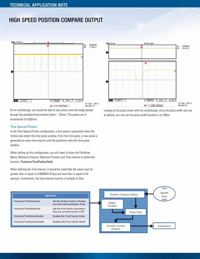
On an oscilloscope, you would be able to see pulses once the stage passesthrough the predetermined window (5mm – 25mm). The pulses are inincremental of 0.002mm.
Time Spaced PulsesIn the Time Spaced Pulses configuration, a first pulse is generated when themotion axis enters the time pulse window. From this first pulse, a new pulse isgenerated at every time interval until the positioner exits the time pulsewindow.
When setting up this configuration, you will need to know the PositionerName, Minimum Position, Maximum Position and Time Interval to define thefunction, PostionerTimeFlasherSet().
When defining the Time Interval, it should be noted that the value must begreater than or equal to 0.0000004 (0.4µs) and less than or equal to 50seconds. Furthermore, the time interval must be a multiple of 25ns.
Looking at the pulse closer with the oscilloscope, since the pulse width was setat default, you can see the pulse width duration is at 200ns.
HIGH SPEED POSITION COMPARE OUTPUT
TECHNICAL APPLICATION NOTE
Commands:PositionerTimeFlasherSet()PositionerTimeFlasherGet()PositionerTimeFlasherEnable()PositionerTimeFlasherDisable()
Example:The example will use the XPS default naming of a stage name “Group1” andthe default positioner name “Group1.Pos”. It is also assumed that thePositionerPositionComparePulseParametersSet has been set to default; ifa different setting is required, please configure this function first.
GroupInitialize(Group1)GroupHomeSearch(Group1)PositionerTimeFlasherSet(Group1.Pos,5,25,0.00001)PositionerTimeFlasherEnable(Group1.Pos)PositionerTimeFlasherGet(Group1.Pos,&MinimumPosition,&MaximumPosition,&PositionStep,&EnableState)
This function returns the parameters previously defined, the minimum position5, the maximum position 25, the time interval 0.00001 and the enabled state(1=enabled,0=disabled)
GroupMoveAbsolute(Group1,30)PositionerTimeFlasherDisable(Group1.Pos)
A Q U A D B E N C O D E R S I G N A L P U L S E SIn the AquadB configuration, AquadB encoder signals are used to output on thePCO connector. These signals can be configured to produce outputs when thepositioner is within a defined position window or outputs continuously at everyencoder signal.
When used with a stage with a digital encoder (AquadB), the AquadB signalpulses will be the same as the encoder signals of the stage. When used with aSin/Cos encoder (AnalogInterpolated), the resolution of the encoder signal willdefine the signal period of the encoder and the setting of the hardwareinterpolator by the function.
When setting up this configuration, you will need to know the Positioner Name,Minimum Position and Maximum Position to define the function,PostionerPositionCompareAquadBWindowedSet(), unless it is desired toalways remain enable, PostionerPositionCompareAquadBAlwaysEnable(),
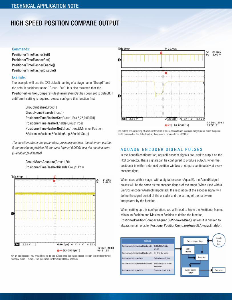
On an oscilloscope, you would be able to see pulses once the stage passes through the predeterminedwindow (5mm – 25mm). The pulses time interval is 0.00002 seconds.
The pulses are outputting at a time interval of 0.00002 seconds and looking a single pulse, since the pulsewidth remained at the default value, the duration remains to be at 200ns.

HIGH SPEED POSITION COMPARE OUTPUT
TECHNICAL APPLICATION NOTE
Commands:PositionerPositionCompareAquadBWindowedSet()PositionerPositionCompareAquadBWindowedGet()PositionerPositionCompareEnable()PositionerPositionCompareAquadBAlwaysEnable()PositionerPositionCompareDisable
Example:The example will use the XPS default naming of a stage name “Group1” andthe default positioner name “Group1.Pos”. It is also assumed that thePositionerPositionComparePulseParametersSet has been set to default; ifa different setting is required, please configure this function first.
GroupInitialize(Group1)GroupHomeSearch(Group1)PositionerPositionCompareAquadBWindowedSet
(Group1.Pos,10,20)PositionerPositionCompareEnable(Group1.Pos)PositionerPositionCompareAquadBWindowedGet
(Group1.Pos,&MinimumPosition,&MaximumPosition,&EnableState)
This function returns the parameters previously defined, the minimum position5, the maximum position 25 and the enabled state (1=enabled,0=disabled)
GroupMoveAbsolute(Group1,30)PositionerTimeFlasherDisable(Group1.Pos)
When using the command PositionerPositionCompareAquadBAlwaysEnable,you do not have to set a window and the pulse will remain on and the image willbe similar to the above image, but pulses will output throughout the travel of thestage.
V A L I D S E T T I N G A S A F U N C T I O N O F S C A NV E L O C I T Y A N D P C O P U L S E S E T T L I N G T I M E
Determine PCO encoder frequency:AquadB encoder:
PCO encoder frequency = ScanVelocity / EncoderResolutionAnalog Sin/Cos encoder:
PCO encoder frequency = ScanVelocity * HardInterpolatorFactor / EncoderScalePitch
Example: ScanVelocity = 10 mm/s, EncoderScalePitch = 0.004 mm,
HardInterpolatorFactor = 200 => PCO encoder frequency = 10 * 200 / 0.004 =500000 = 500 kHz
Pulse Settlingtime (µs)
PCO encoder frequency (kHz)
25 50 125 >500
0.075 OK OK
1 OK OK
4 OK OK
12 OK
When changing the PCO pulse settling time you must limit the maximum velocityof the stage accordingly otherwise you will lose the PCO position and generatethe wrong number of pulses at incorrect positions. As per the above table, if youset the pulse settling time to 4 µs, the maximum PCO encoder frequency needsto be limited to less than 0.25 / 4x 10-6 = 62.5 kHz.
So, if EncoderScalePitch = 0.004 mm and HardInterpolatorFactor = 200 then theScanVelocity must ≤ 62.5 x 103 * 0.004 / 200 = 1.25 mm/s, otherwise the PCOwill not work properly.
On an oscilloscope, you would be able to see pulses once the stage passesthrough the predetermined window (10mm – 20mm). As you can see, thepulses represent an image of the encoder signal.