high-speed programmable limit switch 2500
TRANSCRIPT

High-Speed Programmable Limit Switch
2500High-Speed PLS
Series 956
ABSOLUTE PROCESS CONTROL KNOW WHERE YOU ARE... REGARDLESS
INSTALLATION MANUAL
2500 Series
www.comoso.com

2 1080 N. Crooks Road • Clawson, MI 48017 • 800.635.0289 • Fax 248.435.8120 • www.AMETEKAPT.com
Preface
This manual is for the Installation and Maintenance of the Gemco 2500 Programmable Limit Switch.
AMETEK has checked the accuracy of this manual at the time it was printed. Any comments you may have for the improvement of this manual are welcomed.
AMETEK reserves the right to revise and redistribute the entire contents or selected pages of this manual. All rights to the contents of this manual are reserved by AMETEK.
WARNING: Caution must be taken when adjusting limit outputs!
Disconnect power before servicing. The Gemco 2500 PLS contains no serviceable components other than relays and fuses. Consult factory for repair or replacement.
www.comoso.com

31080 N. Crooks Road • Clawson, MI 48017 • 800.635.0289 • Fax 248.435.8120 • www.AMETEKAPT.com
ContentsChapter 1: Introduction ............................. 41.1 Mechanical Cams .................................. 51.2 Description ............................................. 51.3 Standard Features ................................. 7
Chapter 2: Hardware Overview ................ 92.1 PLS Module ........................................... 92.2 Remote Operator Interface ...................112.3 Expansion Modules ..............................112.4 Resolver Assembly .............................. 122.5 Status Display/Programming Keys ...... 142.6 Dimension Drawings ............................ 16
Chapter 3: Mounting and Wiring ............ 203.1 Mechanical Installation ........................ 203.2 Electrical Installation ............................ 213.3 Wiring Instructions ............................... 21
Chapter 4: Programming ........................ 304.1 Main Controller Keypad ....................... 304.2 Programming Keys Defi ned ................. 314.3 Before You Start .................................. 324.4 Menu Tree ........................................... 334.5 User and Supervisor Mode Access ..... 33
Chapter 5: Global Parameters ................ 355.1 Quick Start ........................................... 355.2 Initialize System ................................... 365.3 Expansion Boards ............................... 375.4 Lockout Functions ............................... 385.5 Scale Factor ........................................ 395.6 Customize Decimal Pt. (Decimal Location) ............................... 405.7 Electronic Offset .................................. 415.8 Motion Detect ...................................... 425.9 Enable Brake Input .............................. 435.10 Brake Monitor .................................... 435.11 Set Fault Clear Option ....................... 455.12 Customize Display ............................. 465.13 Defi ne Title Screen ............................ 475.14 Label Outputs .................................... 485.15 Label Inputs ....................................... 495.16 Defi ne User Password ....................... 505.17 Defi ne Supervisor Password ............. 515.18 Software Version ............................... 52
Chapter 6: Limit Switch Outputs ............ 536.1 Setpoint Data ....................................... 54
Chapter 7: Multiple Program .................. 567.1 Naming A Program .............................. 577.2 Editing A Program ................................ 587.3 Copying A Program .............................. 597.4 Accessing A Program ........................... 607.5 Initialize Program ................................. 61
Chapter 8: Linear Speed Compensation 628.1 Linear Speed Compensation ............... 648.2 Minimum Speed Disable ...................... 65
Chapter 9: Time Based Outputs ............. 66
Chapter 10: Inputs ................................... 6710.1 Input Confi guration ............................ 7110.2 Input Confi guration for No Input ........ 7310.3 Input Confi guration for Reset to Preset Continuous ............... 7410.4 Input Confi guration for Reset to Preset Single ....................... 7510.5 Input Confi guration for Output Enable One Shot ................... 7610.6 Input Confi guration for Output Enable Level .......................... 7710.7 Enable Brake Input ............................ 78
Chapter 11: Die Protection Inputs .......... 7911.1 Applications for Die Protection Inputs 7911.2 Input Confi guration for Die Protect Momentary ...................... 8211.3 Input Confi guration for Die Protect Maintain .......................... 8311.4 Input Confi guration for Die Protect Partial .............................. 84
Chapter 12: Faults ................................... 85
Appendix A: Ordering Information ........ 89
Appendix B: Specifi cations .................... 90B.1: Main Controller Specifi cations ............ 90B.2: Expansion Module Specifi cations ...... 91B.3: Remote Operator Interface Specifi cations .................................... 91
www.comoso.com

4 1080 N. Crooks Road • Clawson, MI 48017 • 800.635.0289 • Fax 248.435.8120 • www.AMETEKAPT.com
Chapter 1: Introduction
The 2500 PLS is a high speed resolver based Programmable Limit Switch that monitors rotary machine position and provides discrete limit switch outputs. These outputs are updated at a much faster rate than can be accomplished using any conventional PLC.
The single turn resolver is usually coupled to the machine shaft at a 1:1 ratio so that one resolver shaft rotation corresponds to one machine cycle. As the resolver rotates it generates a ratiometric analog signal representing an absolute rotary position. The ratiometric signal is converted to a digital signal at the 2500 PLS. Resolvers have no brushes, contacts, or any frictional parts to wear out.
As the resolver passes through the user programmed dwell settings, the 2500 PLS turns electrical switches, known as outputs, on and off. Outputs can energize solenoids, relays, or solid-state circuitry to control external devices. Because the 2500 PLS is completely electronic and has no frictional parts, it offers several advantages over mechanical cam switches:
• Long life with no parts to wear out.• Easy to use menu driven displays.• Setpoints can be adjusted instantly
from the controller.• Adjustments can be made while the
machine is running.• Programmable inputs allow for complex
output functions that are impossible with mechanical cams.
• Operating speeds up to 2,000 RPM.
www.comoso.com

51080 N. Crooks Road • Clawson, MI 48017 • 800.635.0289 • Fax 248.435.8120 • www.AMETEKAPT.com
1.1 Mechanical Cams
The 2500 Programmable Limit Switch electronically simulates mechanical cam switches. A mechanical cam consists of a mechanical limit switch and a roller follower whose roller follower rides on the cam assembly as shown in Figure 1. The camshaft is driven by the machine at a 1:1 ratio so that the cam limit switch turns ON and OFF at specifi c positions in the machine cycle. Cam limit switches have the following disadvantages:
• The roller follower and limit switches wear out.
• The machine must be stopped during adjustment.
• On/off patterns are limited to typically one on and one off per cam. Multiple on and off points require custom cams.
• The mechanical cam switches are typically not installed in an easily accessible location.
• They cannot run at high speeds because of contact bounce and mechanical wear.
1.2 Description
The 2500 is a family of PLS’s that offer unparalleled fl exibility. The main controller is a resolver-based controller that consists of 8 input and 8 output relays, one fault check output relay and one optional brake monitor input relay.
The optional expansion module will provide 8 additional inputs and outputs per module. Up to 7 expansion modules can be driven by the controller for a total of 64 inputs and 64 outputs.
The 2500 PLS uses a unique, easy to understand programming sequence. The traditional number buttons have been
replaced with a rotary knob and the main controller has a 2x24 vacuum fl uorescent display along with 4 pushbutton keys for programming.
The keys have been defi ned as MENU, and . The rotary knob scrolls
you easily through the menu drive alphanumeric display. On-line help screens have been added to aid in the setup and troubleshooting of the unit.
System parameters are entered through a scrolling menu, which is accessed through the main display. The rotary knob is used to scroll through the selections and the key is used to select the menu item. The user can view any system value without entering a password. However, if the user wants to change a value, a password is required.
All the parameters are password protected. Once the password is entered, the user will be allowed to edit any value as long as the user does not return to the main display and the program input is in the correct state.
System data such as position, RPM, and brake monitor status will be shown on the main display. This data can be toggled through using the rotary knob.
Figure 1-1: 1980 Rotating Cam Limit Switch
www.comoso.com

6 1080 N. Crooks Road • Clawson, MI 48017 • 800.635.0289 • Fax 248.435.8120 • www.AMETEKAPT.com
2500 Stand Alone Main Controller
Clawson, MI 48017 U.S.A.
NP0197900
R
ENTER
SCROLL
MENU
2500 SERIES PLS
• 8 Isolated DC Inputs and 8 Solid-State AC or DC Outputs, Expandable to 64 (in groups of 8) using 2500E Expansion Modules
• Rotary Knob with Simple, Menu Driven Programming and Help Menus
• Brake Monitor• 2 x 24 Vacuum Fluorescent Display• Panel Mountable
2500R Remote Operator Interface
Clawson, MI 48017 U.S.A.
NP0197900
R
ENTER
SCROLL
MENU
2500 SERIES PLS
• Keypad only, used with 2500C Blind Main Controller Units• 2 x 24 Vacuum Fluorescent Display• Panel Mountable, up to 25 feet from Main Controller• Simple RJ45 Connections to Main Controller• Rotary Knob, with Scrolling, Menu Driven Programming
2500C Blind Main Controller Units
w
SD
EC
TR
5
V
F 4
A 2
50V
VS
CD
E
TR
5
wF
4A
250V
w
CVD
ES
TR
5
F 4
A 2
50V C
VDE
ST
R5
wF
4A
250V
wTR
5C
VDE
S F 4
A 2
50V
DE
SC
VTR
5
wF
4A
250V
w
CVD
ES
TR
5
F 4
A 2
50V C
VDE
ST
R5
wF
4A
250V
INPUT STATUS
OUT6 OUT8OUT7OUT5OUT4
IN8IN7IN5 IN6IN4
OUT1 OUT2 OUT3BK IN
AC POWER
50/60 Hz
INTERNALLY FUSED
100-240 VAC
IN3IN2IN1
GN
DL2L1
2500CBXXXX2500 SERIES PLS
SERIAL No. >>>>>> D/C >>>>Clawson, MI 48017 U.S.A.
R
• 8 Isolated DC Inputs and 8 Solid-State AC or DC Ouptuts, Expandable to 64 (in groups of 8) using 2500E Expansion Modules • Brake Monitor• Panel or DIN Rail Mountable
2500E Expansion Modules
w
SD
EC
TR
5
V
F 4
A 2
50
V
VS
CD
E
TR
5
wF
4A
25
0V
w
CVD
ES
TR
5
F 4
A 2
50
V CVD
ES
TR
5
wF
4A
25
0V
wTR
5C
VDE
S F 4
A 2
50
V
DE
SC
VTR
5
wF
4A
25
0V
w
CVD
ES
TR
5
F 4
A 2
50
V CVD
ES
TR
5
wF
4A
25
0V
IN4
INPUT STATUS
IN1 IN2 IN3 IN6IN5 IN7 IN8
INTERNALLY FUSED
L1
100-240 VAC50/60 Hz
AC POWER
GN
DL2
OUT4OUT1 OUT2 OUT3 OUT6OUT5 OUT7 OUT8
SERIAL No. >>>>>> D/C >>>>
2500EXXXXX
Clawson, MI 48017 U.S.A.
2500 SERIES PLS
R
• 8 Isolated DC Inputs and 8 Solid-State AC or DC Outputs• Panel or DIN Rail Mountable• Up to 7 Expansions Modules can be Driven From the Main Controller• Simple Depluggable Connections
2500 PLS confi gurations include:
www.comoso.com

71080 N. Crooks Road • Clawson, MI 48017 • 800.635.0289 • Fax 248.435.8120 • www.AMETEKAPT.com
1.3 Standard Features
Scale Factor The Scale Factor is the number of increments that the PLS counts through over one rotation of the resolver. For example, a PLS with a Scale Factor of 360 will count from 0 to 359 over one revolution.
Offset The Offset feature is used to electronically synchronize the PLS displayed position with the actual machine position. Valid values are 0 to (one less than the programmed Scale Factor).
Supervisor Menu Two levels of programming access are provided: User and Supervisor. In the Supervisor Menu, display screens can be customized and outputs and functions can be locked out. Each level can be assigned a password that must be entered to program the locked out functions. This can provide key personnel the fl exibility they need while protecting settings against accidental or unauthorized changes.
Onboard Help Onboard Help is available from the 2500 PLS 2x24 alphanumeric vacuum fl uorescent display. Each programming screen has easy to follow English programming screens.
Multi-program The Multi-program feature allows the storage of multiple sets of output sequences that are pre-programmed based on various requirements of different jobs. When jobs are changed, the new program is simply called up from the Interface or remote inputs and all outputs
and inputs are automatically set to the new output sequences. The 2500 PLS is capable of storing 15 different programs.
Program Name The Program Name feature allows the user to assign a name to each program.
Program Copy The Program Copy feature copies all parameters from one program to another. This is useful when inputting data from one program to another where only minor changes are needed.
Brake Monitor The Brake Monitor checks the stopping time of the machine against a selected preset stopping time in milliseconds. A user defi ned output remains energized when the stop time parameters are within tolerance. An excessive stop time will cause the relay to de-energize, which could be used to stop further machine operation.
Motion Detector A programmable Motion Detector output will energize a user selected relay when the transducer speed meets or exceeds the user programmed RPM value.
Fault Check The 2500 PLS offers an on-line Fault Check which provides an automatic, in-process mechanism to verify that all major programmable limit switch functions are operating properly. The fault check output can be energized by activating the fault check enable input. The output is a mechanical relay, which remains energized during normal operation.
www.comoso.com

8 1080 N. Crooks Road • Clawson, MI 48017 • 800.635.0289 • Fax 248.435.8120 • www.AMETEKAPT.com
Input Each Input can be confi gured as either a reset to preset input, an output confi guration enable input, or a die protection input.
Output Enabler The output enable input will enable the setpoints for one revolution when the input is activated in a programmed window. The user can program the window.
Reset to Preset The Reset to Preset feature allows the user to reset a pre-defi ned output to any preprogrammed position. This feature can be used to compensate for mechanical slippage. NOTE: Each output has its own independent reset input.
Reset Single Shot The Reset Single Shot feature allows the user to reset a pre-defi ned output to any pre-programmed position. However, with this feature the output associated with this input waits for the input signal before it allows the output to fi re. Once the input is made, the output will only fi re one time and wait for the next input signal.
Die Protection Die Protection is used in stamping applications where it is necessary to monitor a part as it is progressing through the die. If the part is not detected in the location, an output will signal the press to stop.
Output Enable Output Enable is used in conjunction with an input. If the input is not seen within a programmed range, the output associated with that input will not fi re. Output enables are typically used in gluing applications where if a product is not present, the gluing output does not fi re.
Setpoint Data There are up to eight setpoint pairs available per revolution for each output. The user can add, delete, or change a setpoint in the list. Valid setpoints range from 0 to a value (one less than the current scale factor). For example, if the scale factor is set at 1000, then valid setpoint values range from 0 to 999.
Timed Outputs Time Based outputs are programmed like standard outputs to turn on at a specifi c resolver position and stay on for a programmable amount of time.
Minimum Speed The Minimum Speed Disable will disable the selected outputs when the Disable actual RPM falls below the minimum speed programmed by the user. Valid minimum speed values range from 0 to 2048. A value of zero will disable this feature. The default value is zero.
Linear Speed Linear Speed Compensation allows for setpoints to be adjusted to compensate for mechanical lag at higher speeds. Each output can be programmed with its own adjusted values. The user will program an on offset and an off offset and the RPM that is associated with that offset. The unit will linearize the offset values and adjust the setpoints for that output based on the actual RPM value. Software Version The software version can be viewed through the Software Version menu item. The version number will follow our standard numbering system with two digits before the decimal indicating major releases and the two digits after the decimal indicating minor releases.
www.comoso.com

91080 N. Crooks Road • Clawson, MI 48017 • 800.635.0289 • Fax 248.435.8120 • www.AMETEKAPT.com
This section contains mechanical and electrical information on the 2500 PLS main controller, expansion modules, remote operator interface, and resolver assembly. For specifi cations, see Appendix B.
2.1 PLS Module
The 2500 PLS module is an electronic assembly that can be confi gured many different ways. The three main parts are described in Chapter 1. The following are features found on the module:
• A rotary knob replaces the standard number buttons. As the knob is rotated, it helps guide you through the programming process. Convenient help screens guide you through the entire programming process.
• A 2 line x 24 character vacuum fl uorescent display indicates all PLS functions.
• Eight depluggable solid-state output relays are located on the back of the controller. Each output has its own input located on the opposite side of the controller.
• An optional depluggable Brake monitor input relay is located on the back of the controller. This input can be used to determine stopping time of the machine.
• The auxiliary communication port currently supports Modbus ASCII protocol.
• Resolver input terminals allow connection to a Gemco resolver or compatible equipment.
• Expansion ports allow for further relay expansion. The main controller is capable of driving 64 outputs and inputs.
• Fault check. A mechanical relay output is held closed as long as the PLS is working properly. If the PLS resolver circuitry or microprocessor fails, the relay will open.
• Universal input power. The 2500 PLS can operate over a wide input range, 100 - 240 VAC, 50/60 Hz.
Chapter 2: Hardware Overview
www.comoso.com

10 1080 N. Crooks Road • Clawson, MI 48017 • 800.635.0289 • Fax 248.435.8120 • www.AMETEKAPT.com
Clawson, MI 48017 U.S.A.NP0197900
R
ENTER
SCROLL
MENU
2500 SERIES PLS
w
SDE
C
TR5
V
F 4A 250V
VS
CDE
TR5
wF 4A 250V
w
CVDE
STR5
F 4A 250V
CVDE
STR5
wF 4A 250V
wTR5
CVDE
S F 4A 250V
DE
SC
VTR5
wF 4A 250V
w
CVDE
STR5
F 4A 250V
CVDE
STR5
wF 4A 250V
INPUT STATUS
IN8IN7IN5 IN6IN4
100-240 VAC
INTERNALLY FUSED
IN1
50/60 Hz
IN3IN2
AC POWER
GN
DL2L1
OUT4 OUT6OUT5 OUT7 OUT8OUT2 OUT3OUT1BK IN
Figure 2-1: 2500CF Main Controller
Figure 2-2: 2500CB Blind Main Controller
w
SD
EC
TR
5
V
F 4
A 2
50V
VS
CD
E
TR
5
wF
4A
250V
w
CVD
ES
TR
5
F 4
A 2
50V C
VDE
ST
R5
wF
4A
250V
wTR
5C
VDE
S F 4
A 2
50V
DE
SC
VTR
5
wF
4A
250V
w
CVD
ES
TR
5
F 4
A 2
50V C
VDE
ST
R5
wF
4A
250V
EX
PA
NS
ION
OU
T
INPUT STATUS
OUT6 OUT8OUT7OUT5OUT4
IN8IN7IN5 IN6IN4
OUT1 OUT2 OUT3BK IN
AC POWER
50/60 Hz
INTERNALLY FUSED
100-240 VAC
IN3IN2IN1
GN
DL2L1
2500CBXXXX2500 SERIES PLS
SERIAL No. >>>>>> D/C >>>>Clawson, MI 48017 U.S.A.
R
www.comoso.com

111080 N. Crooks Road • Clawson, MI 48017 • 800.635.0289 • Fax 248.435.8120 • www.AMETEKAPT.com
Clawson, MI 48017 U.S.A.NP0197900
R
ENTER
SCROLL
MENU
2500 SERIES PLS
The Remote Operator Interface connects to the main controller through an 8-pin Ethernet cable commonly know as an RJ45. Full duplex RS-485 is used to communicate to the main controller. The remote operator interface is made up of a 2x24 vacuum fl uorescent display, along
with four pushbutton keys and a rotary knob for programming. The keys have been defi ned as MENU, , and . The 2500R Remote Operator Interface can be used with the 2500CB main controller unit. This allows a means of mounting the main controller unit remotely.
2.2 Remote Operator Interface
Figure 2-3: 2500R Remote Operator Interface
2.3 Expansion Modules
The standard 2500 PLS is supplied with 8 inputs and 8 outputs. The system is expandable to 64 inputs and 64 outputs by adding the 2500E Expansion Module. Each expansion module consists of 8 output modules and 8 inputs. These solid-state outputs are an optically isolated barrier between the PLS and the fi eld devices they control. These output modules are also pluggable and either AC or DC relays can be used.
• Panel mount or DIN rail mountable.
• Plug and play cable design.
• Pluggable output relays.
• No increase in update time regardless of number of Expansion Modules.
• LED’s are located next to each input and output. These LED’s specify the state of each input and output.
www.comoso.com
12 1080 N. Crooks Road • Clawson, MI 48017 • 800.635.0289 • Fax 248.435.8120 • www.AMETEKAPT.com
Stator 1 Voltage
Stator 2 Voltage
90 180 270 360
Ratiometric conversion of the two secondary coil voltages provides absolute position data, and factors out EMI.
w
SD
EC
TR
5
V
F 4
A 2
50V
VS
CD
E
TR
5
wF
4A
250V
w
CVD
ES
TR
5
F 4
A 2
50V C
VDE
ST
R5
wF
4A
250V
wTR
5C
VDE
S F 4
A 2
50V
DE
SC
VTR
5
wF
4A
250V
w
CVD
ES
TR
5
F 4
A 2
50V C
VDE
ST
R5
wF
4A
250V
IN4
INPUT STATUS
IN1 IN2 IN3 IN6IN5 IN7 IN8
INTERNALLY FUSED
L1
100-240 VAC50/60 Hz
AC POWER
GN
DL2
OUT4OUT1 OUT2 OUT3 OUT6OUT5 OUT7 OUT8
EX
PA
NS
ION
OU
T
SERIAL No. >>>>>> D/C >>>>
2500EXXXXX
Clawson, MI 48017 U.S.A.
2500 SERIES PLS
R
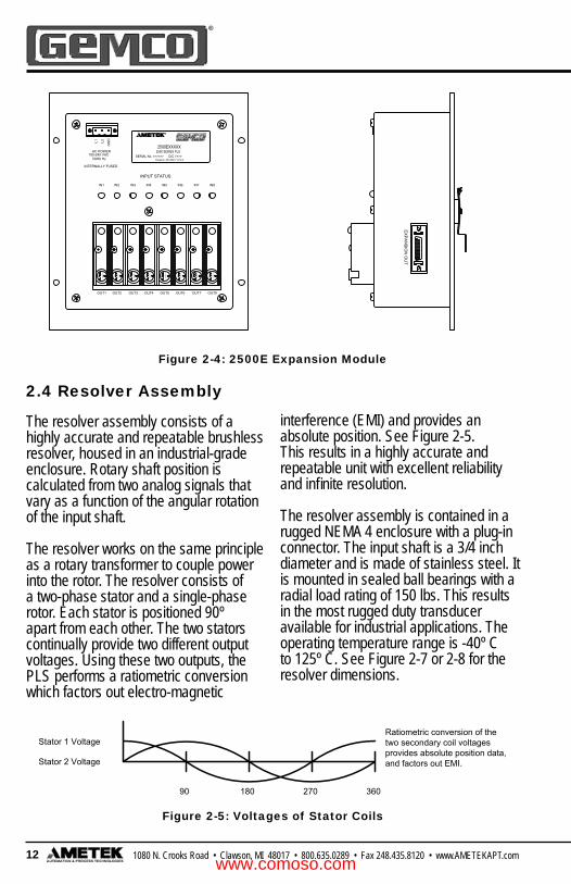
2.4 Resolver Assembly
The resolver assembly consists of a highly accurate and repeatable brushless resolver, housed in an industrial-grade enclosure. Rotary shaft position is calculated from two analog signals that vary as a function of the angular rotation of the input shaft.
The resolver works on the same principle as a rotary transformer to couple power into the rotor. The resolver consists of a two-phase stator and a single-phase rotor. Each stator is positioned 90º apart from each other. The two stators continually provide two different output voltages. Using these two outputs, the PLS performs a ratiometric conversion which factors out electro-magnetic
interference (EMI) and provides an absolute position. See Figure 2-5. This results in a highly accurate and repeatable unit with excellent reliability and infi nite resolution.
The resolver assembly is contained in a rugged NEMA 4 enclosure with a plug-in connector. The input shaft is a 3/4 inch diameter and is made of stainless steel. It is mounted in sealed ball bearings with a radial load rating of 150 lbs. This results in the most rugged duty transducer available for industrial applications. The operating temperature range is -40º C to 125º C. See Figure 2-7 or 2-8 for the resolver dimensions.
Figure 2-4: 2500E Expansion Module
Figure 2-5: Voltages of Stator Coils
www.comoso.com

131080 N. Crooks Road • Clawson, MI 48017 • 800.635.0289 • Fax 248.435.8120 • www.AMETEKAPT.com
1.42
2.25
1.08
.7475.7490
DIA..75
1.38
.622.50
8.508.00
2.12
5.50
4.25
KEY#606 WOODRUFF
.38
(52.58)
8.88 w/ ST.
CONN.
2.50
3.74
2 PLACES.44 (11.18) DIA. MOUNTING HOLES
8.00 w/ R.A. CONN.
(139.70)
(107.95)
(53.85)
(15.75)(63.50)
(203.20)
(215.90)
(225.55)
(203.20)
(35.05)(19.05)
(36.07) (27.43)
(57.15)
(63.50)
(95.00)
2.07
(9.65)
(19.02)(18.99)
(COSINE)
YELLOW/WHITE
RED/WHITE
2500 PROGRAMMABLE LIMIT SWITCHTO TERMINALS OF GEMCO
RESOLVER CABLESD0508200LX
TRANSDUCER
RESOLVER
BLACK
GREEN
BLACK
ALPHA CABLE 6053COLOR CODE
R2
S4
S2
S1
S3 WHITE
BLACK
R1 RED
S1
STATOR
B
F
E
D
C
A
S4 S2(SINE)
STATOR
ROTOR
R1 R2
S3
BLACK
YELLOW RESOLVER COLOR CODE
RESOLVER HOUSINGJUMPER INSIDE
BLUE
RED
B
C D
G
FA
E
YELLOW
BLUE
RED
BLACKWHITE
E
F
D
C
RED/WHITE
YELLOW B
A
RESOLVER
Figure 2-6: Reslover Wiring
Figure 2-7: 1986 “A” Style Brushless Resolver
NOTE: Other Gemco resolver assemblies are available. Contact factory for details.
www.comoso.com

14 1080 N. Crooks Road • Clawson, MI 48017 • 800.635.0289 • Fax 248.435.8120 • www.AMETEKAPT.com
(TOTAL CLEARANCE OF 5.5"REQUIRED FOR REMOVALOF MATING CONNECTOR)
[ ] = DIMENSIONS IN MILLIMETERS
CONNECTOR: MS3102E16S-1P
1/4-20 UNC-2B.50 [12.7] DEEP
(8 PLACES)
SEE KEYWAYSPECIFICATIONS
1.25
[31.
8].150 [3.8]
1.500 [38.1].500
[12.7]
3.250 [82.6]
4.87[123.7]
.750[19.1]
2.500[63.5]2.000
[50.8]
1.000[25.4]
.250 [6.4]
.250 [6.4]
2.000 [50.8]
.673 [17.1]
1.180[30.0]
.6247
.6237[15.87][15.84]
Side mountconnector
Rear mount connector
.673 [17.1]
2.50[63.5]
Clawson, MI 48017 U.S.A.NP0197900
R
ENTER
SCROLL
MENU
2500 SERIES PLS
Shift Keys:Moves cursor rightor left.
Menu Key:Used to access menu drivendisplay.
2 x 24 Alpha Numeric:Vacuum Fluorescent Display.
POS 12345RPM 2000
Rotary Knob:The Rotary knob is used to scroll and move through the menu driven displays.
Enter Key:Enter must be pressedto enter a value.
Figure 2-8: 1986 “F” Style Brushless Resolver
The 2500 PLS has a 2 line by 24 character vacuum fl uorescent display (VFD), four programming buttons and a rotary knob. The VFD provides
programming and status information. The programming keys and rotary knob are used to program functions and perform basic operations.
Figure 2-9: Main Controller (Front View)
2.5 Status Display/Programming Keys
www.comoso.com
151080 N. Crooks Road • Clawson, MI 48017 • 800.635.0289 • Fax 248.435.8120 • www.AMETEKAPT.com
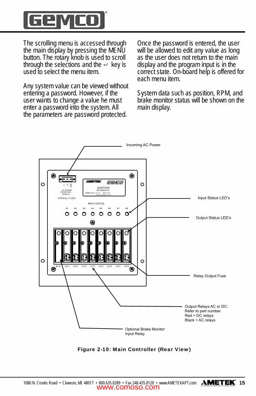
Incoming AC Power
Input Status LED’s
Output Status LED’s
Relay Output Fuse
Output Relays AC or DC:Refer to part numberRed = DC relaysBlack = AC relays
Optional Brake MonitorInput Relay
w
SD
EC
TR
5
V
F 4
A 2
50
V
VS
CD
E
TR
5
wF
4A
25
0V
w
CVD
ES
TR
5
F 4
A 2
50
V CVD
ES
TR
5
wF
4A
25
0V
wTR
5C
VDE
S F 4
A 2
50
V
DE
SC
VTR
5
wF
4A
25
0V
w
CVD
ES
TR
5
F 4
A 2
50
V CVD
ES
TR
5
wF
4A
25
0V
IN8IN7IN5 IN6IN4
100-240 VAC
INTERNALLY FUSED
IN1
50/60 Hz
IN3IN2
AC POWER
GN
DL2L1
OUT4 OUT6OUT5 OUT7 OUT8OUT2 OUT3OUT1BK IN
SERIAL No. >>>>>> D/C >>>>Clawson, MI 48017 U.S.A.
2500 SERIES PLS2500CFXXXX
R
INPUT STATUS
Figure 2-10: Main Controller (Rear View)
The scrolling menu is accessed through the main display by pressing the MENU button. The rotary knob is used to scroll through the selections and the key is used to select the menu item.
Any system value can be viewed without entering a password. However, if the user wants to change a value he must enter a password into the system. All the parameters are password protected.
Once the password is entered, the user will be allowed to edit any value as long as the user does not return to the main display and the program input is in the correct state. On-board help is offered for each menu item.
System data such as position, RPM, and brake monitor status will be shown on the main display.
www.comoso.com

16 1080 N. Crooks Road • Clawson, MI 48017 • 800.635.0289 • Fax 248.435.8120 • www.AMETEKAPT.com
6.31
7.50
4.73
.54
.13 3.32
3.98
4.50
1.50
5.88.22
.66
6.19
5.31.50
.18 (4 PLACES)
5.88
.22 5.43
6.31 4.50
.90
PANEL CUT OUTDIMENSIONS #8-32 UNC-2B
(4 PLACES)
Clawson, MI 48017 U.S.A.NP0197900
R
ENTER
SCROLL
MENU
2500 SERIES PLS
w
SDE
C
TR5
V
F 4A 250V
VS
CDE
TR5
wF 4A 250V
w
CVDE
STR5
F 4A 250V
CVDE
STR5
wF 4A 250V
wTR5
CVDE
S F 4A 250V
DE
SC
VTR5
wF 4A 250V
w
CVDE
STR5
F 4A 250V
CVDE
STR5
wF 4A 250V
IN8IN7IN5 IN6IN4
100-240 VAC
INTERNALLY FUSED
IN1
50/60 Hz
IN3IN2
AC POWER
GN
DL2L1
OUT4 OUT6OUT5 OUT7 OUT8OUT2 OUT3OUT1BK IN
SERIAL No. >>>>>> D/C >>>>Clawson, MI 48017 U.S.A.
2500 SERIES PLS2500CFXXXX
R
INPUT STATUS
2.6 Dimension Drawings
Figure 2-11: 2500CF Main Controller Dimensions
www.comoso.com

171080 N. Crooks Road • Clawson, MI 48017 • 800.635.0289 • Fax 248.435.8120 • www.AMETEKAPT.com
w
SD
EC
TR
5
V
F 4
A 2
50
V
VS
CD
E
TR
5
wF
4A
25
0V
w
CVD
ES
TR
5
F 4
A 2
50
V CVD
ES
TR
5
wF
4A
25
0V
wTR
5C
VDE
S F 4
A 2
50
V
DE
SC
VTR
5
wF
4A
25
0V
w
CVD
ES
TR
5
F 4
A 2
50
V CVD
ES
TR
5
wF
4A
25
0V
EX
PA
NS
ION
OU
T
INPUT STATUS
OUT6 OUT8OUT7OUT5OUT4
IN8IN7IN5 IN6IN4
OUT1 OUT2 OUT3BK IN
AC POWER
50/60 Hz
INTERNALLY FUSED
100-240 VAC
IN3IN2IN1
GN
DL2L1
6.31
7.50
5.88.22
1.50
4.50
.18(4 PLACES)
5.31.50
6.19
.66
4.20
3.32 .13
.90
4.506.31
.22
(4 PLACES)PANEL CUT OUT
(HALF SCALE)
DIMENSIONS#8-32 UNC-2B
5.43
5.88
.36
OPTIONAL 35MM DIN RAIL MOUNTING HARDWARE
2500CBXXXX2500 SERIES PLS
SERIAL No. >>>>>> D/C >>>>Clawson, MI 48017 U.S.A.
R
Figure 2-12: 2500CB Blind Main Controller Dimensions
www.comoso.com

18 1080 N. Crooks Road • Clawson, MI 48017 • 800.635.0289 • Fax 248.435.8120 • www.AMETEKAPT.com
6.31
7.50
1.82
2.36
4.50
1.50
5.88.22
6.19
.66
.50 5.31
2500RX2500 SERIES PLS
SERIAL No. >>>>>> D/C >>>>
Clawson, MI 48017 U.S.A.NP0197900
R
ENTER
SCROLL
MENU
2500 SERIES PLS
Clawson, MI 48017 U.S.A.
R
.90
4.506.31
.22
(4 PLACES)PANEL CUT OUT
DIMENSIONS
#8-32 UNC-2B
5.43
5.88
Figure 2-13: 2500R Remote Operator Interface
www.comoso.com

191080 N. Crooks Road • Clawson, MI 48017 • 800.635.0289 • Fax 248.435.8120 • www.AMETEKAPT.com
w
SD
EC
TR
5
V
F 4
A 2
50
V
VS
CD
E
TR
5
wF
4A
25
0V
w
CVD
ES
TR
5
F 4
A 2
50
V CVD
ES
TR
5
wF
4A
25
0V
wTR
5C
VDE
S F 4
A 2
50
V
DE
SC
VTR
5
wF
4A
25
0V
w
CVD
ES
TR
5
F 4
A 2
50
V CVD
ES
TR
5
wF
4A
25
0V
IN4
INPUT STATUS
IN1 IN2 IN3 IN6IN5 IN7 IN8
INTERNALLY FUSED
L1
100-240 VAC50/60 Hz
AC POWERG
NDL2
OUT4OUT1 OUT2 OUT3 OUT6OUT5 OUT7 OUT8
6.31 4.50(HALF SCALE)
5.88
5.43
PANEL CUT OUT
.22
.90
DIMENSIONS #8-32 UNC-2B(4 PLACES)
3.39
.132.51
6.31
7.50 4.50
1.50
6.19
.66
5.88.22
5.31.50
.18(4 PLACES)
EX
PA
NS
ION
OU
T
.36
OPTIONAL 35MM DIN RAIL MOUNTING HARDWARE
SERIAL No. >>>>>> D/C >>>>
2500EXXXXX
Clawson, MI 48017 U.S.A.
2500 SERIES PLS
R
Figure 2-14: 2500E Expansion Module
www.comoso.com

20 1080 N. Crooks Road • Clawson, MI 48017 • 800.635.0289 • Fax 248.435.8120 • www.AMETEKAPT.com
This section describes the installation and wiring of the 2500 PLS family. Changes to these instructions should be made as necessary if special options and/or equipment are used.
The 2500 PLS should be installed in an area free of water spray, corrosive gases, fl ying chips or other foreign matter. The operating temperature should be between 32 and 125 degrees Fahrenheit, with less than 95% relative humidity.
3.1 Mechanical Installation
Mounting the 2500 PLSThe 2500 PLS is designed to be panel or DIN-rail mounted. The face of the 2500 can be affected by water and/or oil spray. Provisions should be made to
protect the face of the unit from spraying or splashing.
Panel cutouts, mounting holes and sizes for each component are shown in Chapter 2.
The controller should be mounted in the appropriate panel cutout and securely bolted into place using the four (4) 3/6” diameter mounting holes. A DIN-rail mounting kit is supplied with all blind main controller units and expansion modules for an optional means of mounting. See Fig. 3-1.
NOTE: In instances where the 2500 is being mounted directly on high vibration machinery, care should be taken to isolate the controller from shock load and vibration.
It is always good design practice to mount the controller in the enclosure as far away from the motor starters and control relays as possible to minimize the effects of electromagnetic interference (EMI).
Interconnecting wiring should also be routed to minimize EMI coupling.
To attach DIN-rail to the Expansion Module or Blind Main Controller unit, place the two supplied 8-32 x 5/8” lg. screws through the DIN-rail bracket and fi rmly attach to aluminum plate.
Chapter 3: Mounting and Wiring
www.comoso.com

211080 N. Crooks Road • Clawson, MI 48017 • 800.635.0289 • Fax 248.435.8120 • www.AMETEKAPT.com
w
SDE
C
TR5
V
F 4A 250V
VS
CDE
TR5
wF 4A 250V
w
CVDE
STR5
F 4A 250V
CVDE
STR5
wF 4A 250V
wTR5
CVD E
S F 4A 250V
DE
SC
VTR5
wF 4A 250V
w
CVDE
STR5
F 4A 250V
CVDE
STR5
wF 4A 250V
INPUT STATUS
IN8IN7IN5 IN6IN4
100-240 VAC
INTERNALLY FUSED
IN1
50/60 Hz
IN3IN2
AC POWER
GNDL2L1
OUT4 OUT6OUT5 OUT7 OUT8OUT2 OUT3OUT1BK IN
Input Power
Mounting the ResolverThe proper mounting of the resolver is critical to ensure the system’s accuracy. There are many resolvers available. See our full line 1986 Reslover Catalog.
A. Standard foot mounted resolvers. The foot mount resolver should be mounted in an area free of excessive shock and vibration. The resolver should be connected in a 1:1 ratio with the machine.
B. Combination mechanical cam/
resolver systems. Intended as bolt-in replacements to existing switches. The cam/resolver combination unit should be coupled where the existing limit switch is located. Wire and adjust the mechanical cams in accordance with the original manufacturer’s specifi cations and wire the resolver cable to the controller.
NOTE: The 2500 programmable limits are not control reliable for the clutch/brake circuits. Mechanical cam limits must be used for these circuits.
3.2 Electrical Installation
The 2500 PLS is designed for use in an industrial environment and incorporates extensive transient suppression circuitry. However, the same general installation rules should be followed that are used on all microprocessor-based equipment.
Incoming AC lines should be from a clean power source and lines carrying computer level signals should not be routed in the same conduit as high voltage, transient-producing circuits such
as variable speed drives, welders or DC switching circuits.
The 2500 PLS is only used with a single-turn resolver. Wiring for this system is shown in Figures 3-1 through 3-9. These wiring diagrams are applicable for all standard 2500 PLS’s.
3.3 Wiring Instructions
This section contains pinout diagrams for each connector. The terminal wire size for all connectors is No. 22-12 AWG. For system wiring refer to wiring diagram [E0238000].
Input PowerThe 2500 Main Controller and Expansion Modules have a universal input power supply. Input power is 100-240 VAC 50/60 Hz @ 7 watts. This input is internally fused.
www.comoso.com

22 1080 N. Crooks Road • Clawson, MI 48017 • 800.635.0289 • Fax 248.435.8120 • www.AMETEKAPT.com
FAULT CHECK RESET SWITCH IS WIRED AS BELOW, AFTER A FAULT OCCURS, THE FAULT
SINKING) DEVICE, CONNECTED SIMILAR TO ABOVE.NOTE: ALL SWITCHES CAN BE REPLACED BY AN OPEN COLLECTOR (CURRENT
WILL RESUME NORMAL OPERATION.AND RECLOSED (ENABLED), THE FAULT CHECK RELAY WILL RE-ENERGIZE AND THE OUTPUTSIS CORRECTED AND THE CUSTOMER SUPPLIED RESET SWITCH IS OPENED (DISABLED)CHECK RELAY DE-ENERGIZES AND ALL OUTPUT RELAYS DE-ENERGIZE. AFTER THE FAULT
COM
8
(CLOSED)ENABLE
FLT IN
3
PLS CIRCUITRY AS SHOWN BELOW ONLY IF IT IS REQUIRED. IF A CUSTOMER SUPPLIEDTHE USE OF THE FAULT CHECK FEATURE IS OPTIONAL AND SHOULD BE WIRED TO THE
A JUMPER WIRE BETWEEN COM & PGM.IF NO RUN/SECURITY PROGRAM IS NEEDED (ALWAYS IN PROGRAM MODE) INSTALL
TWO METHODS OF WIRING SECURITY SWITCH
WHEN SWITCH IS CLOSED, PLS CAN BE PLACED IN PROGRAM MODE. TYPICAL WIRING FOR CUSTOMER SUPPLIED PROGRAM SECURITY SWITCH.
HAS BEEN ACTUATED - CONTINUITY - BETWEEN COM & PGM INPUT.2500 P.L.S. CANNOT BE PROGRAMMED UNTIL THE PGM INPUT
FAULT CHECK CIRCUIT
COM
8
RUNPROGRAM(CLOSED)
WHEN SWITCH IS OPEN, PLS WILL BE IN RUN MODE. (ALL FUNCTIONS
PROGRAM SECURITY INPUT
PGM
1
OR
CIRCUITRY AS SHOWN BELOW ONLY IF IT IS REQUIRED. TYPICAL WIRING FOR CUSTOMERTHE USE OF THE ENABLE FEATURE IS OPTIONAL AND SHOULD BE WIRED TO THE PLS
DISABLECOM
8 2
ENABLE(OPEN) ENA
ENABLE
OR
OR
CAN BE VIEWED BUT DATA CANNOT BE CHANGED.)
SUPPLIED ENABLE INPUT. WHEN SWITCH IS OPEN, PLS OUTPUTS WILL BE ENABLED.WHEN SWITCH IS CLOSED OUTPUTS WILL BE DISABLED.
++ + ---+-
SE
L
4
FLT IN
PRG
ENA
12
PRG
CO
M 8
+-- +-++-++ + ---+-
RESOLVER
INPUTS
SE
L
4
FLT IN
PR
G
EN
A
12
PR
G
CO
M 8
BK
/RE
D
RE
D
GR
EE
N
BK
/WH
T
WH
ITE
BK
/GR
N
MULTI-PROGRAM SELECTSINKING INPUTS
+5VDC MAXON AT <1VDC @ 5mA
124 378 6 5
FAULT CLEAR ENABLEPROGRAM SECURITY INPUT
Figure 3-4
Resolver Input
The resolver input has a six position connector (see fi gure 3-3). Attach the pre-wired plug on the resolver cable to the resolver and route the shielded cable through a separate grounded (earth ground) metal conduit to the panel. Connect the mating half terminal block to the 2500 PLS. To change count direction switch green (pin 5) and black of green (pin 6).
NOTE: When extensions to the factory supplied resolver cable are necessary, a junction box should be used to connect the wire leads and cable shields from one cable to the other. The junction box is used to isolate the splices of the connecting wires from outside electrical noises. Ground the cable shields at the controller case only. Figure 3-3
Program, Fault Clear, Enable and Multi-Program Inputs
When using a cable other than the standard SD0508200, the shield must be tied to Pin 2 (black of red) and must not be tied at the resolver end.
1 2 3 4 5 6 7 8
+-- +-++-
RESOLVER
INPUTS
BK
/RE
D
RED
GR
EE
N
BK
/WH
T
WH
ITE
BK
/GR
N
BLACK W/GREEN-S4GREEN-S2
WHITE-S1BLACK W/WHITE-S3
BLACK W/RED-RLRED-RH
1986F
CABLE ASSEMBLY - SD0508200LXX
124 36 5
1 2 3 4 5 6 7 8
OR EQUIVALENT
www.comoso.com

231080 N. Crooks Road • Clawson, MI 48017 • 800.635.0289 • Fax 248.435.8120 • www.AMETEKAPT.com
The 2500 has eight inputs that are internally tied to the eight outputs. The input connector is a sixteen position connector. Each input can be confi gured as either a reset-to-preset, an output enabler input or a die protection input. Inputs 1 - 8 require a PNP sourcing device type input signal.
For input wiring examples, see Fig. 3-12.
The Main Controller and Expansion Modules are available with any combination of solid-state AC or DC ouput relays. The Main Controller has one extra optional solid-state Brake Monitor input relay. This relay is located in the far left relay slot and is only used for brake monitoring. This twenty-place connector contains limit switch 1 - 8 solid-state relay outputs, the optional Brake Monitor input and the Fault Check output relay. For output or brake monitor input wiring, see Fig. 3-13 & 3-14.
LIMIT SWITCH OUTPUTS
COMMAUX DISPLAY
BR
AK
EIN
PU
T
FAU
LTC
HEC
K
RESTRM
3- -
+
8
+
7
++
6 5
+
4- -
+ +
2
+
1
+ +
BK F.C.IN
8 7 6 51516 14 1013 1112 9181920 17
SOLID STATE RELAY OUTPUTS.RELAY TYPES SPECIFIED IN THE PART NUMBER.
OUTPUTS
2 1
34
FAULT CHECKSEE NOTES *
90-140VACBRAKE MONITOR INPUT
OPTO 22 P/N: G4IAC5AMETEK P/N: 04523125
LIMIT SWITCH OUTPUTS
COMMAUX DISPLAY
BR
AK
EIN
PU
T
FAU
LTC
HEC
K
RESTRM
3- -
+
8
+
7
++
-6 5
-
+
4- - -
+
-
+
2
+
1
+
-
+
-BK F.C.IN
NOT USED ONMODEL 2500CF.ONLY USEDW/BLIND UNITMODELS.
The remote operator interface connects to the Main Controller through an 8-pin Ethernet cable (part# SD0530100), commonly know as an RJ45. A full duplex RS485 is used to communicate to the Main Controller.
Figure 3-5
Figure 3-6
Figure 3-7
+-- +-++-++ + ---+-
RESOLVER
INPUTS
SE
L
4
FLT IN
PR
G
ENA
12
PR
G
CO
M 8
BK
/RE
D
RE
D
GR
EE
N
BK
/WH
T
WH
ITE
BK
/GR
N
INPUTS 1-8
>1.5mA @ 10V
SOURCING DEVICE10-30VDC ON AT
>4.0mA @ 30V
1 2 3 4 5 6 7 8
Inputs 1-8
Output Relays & Optional Brake Monitor Input
Remote Operator Interface
www.comoso.com

24 1080 N. Crooks Road • Clawson, MI 48017 • 800.635.0289 • Fax 248.435.8120 • www.AMETEKAPT.com
LIMIT SWITCH OUTPUTS
COMMAUX DISPLAY
BR
AK
EIN
PU
T
FAU
LTC
HEC
K
RESTRM
3- -
+
8
+
7
++
-6 5
-
+
4- - -
+
-
+
2
+
1
+
-
+
-BK F.C.IN
RESISTOR JUMPERRS-485 TERMINATION
COMMUNICATIONS PORTRS-485 AUXILLARY
The auxillary RS485 communication port uses a standard RJ11 connector. The communication port has not been defi ned at this time, consult factory.
The standard 2500 PLS is supplied with 8 inputs and 8 outputs. The system is expandable to 64 inputs and 64 outputs by adding the 2500E Expansion Module. Each expansion module consists of 8 output modules and 8 inputs.Simple depluggable cable assemblies
Figure 3-8
NOTE: Connect from Expansion Out of main controller to Expansion In on expansion module.
Figure 3 - 9
Clawson, MI 48017 U.S.A.NP0197900
R
ENTER
SCROLL
MENU
2500 SERIES PLS
Depluggable Expansion CablePart Number SD0528500LX
X = Length in feet 1 & 6 ft length available.
Expansion Module Expansion ModuleMain ControllerExpansion Out Expansion In Expansion Out Expansion In
w
SD
EC
TR
5
V
F 4
A 2
50V
VS
CD
E
TR
5
wF
4A
250V
w
CVD
ES
TR
5
F 4
A 2
50V C
VDE
ST
R5
wF
4A
250V
wTR
5C
VDE
S F 4
A 2
50V
DE
SC
VTR
5
wF
4A
250V
w
CVD
ES
TR
5
F 4
A 2
50V C
VDE
ST
R5
wF
4A
250V
IN4
INPUT STATUS
IN1 IN2 IN3 IN6IN5 IN7 IN8
INTERNALLY FUSED
L1
100-240 VAC50/60 Hz
AC POWER
GN
DL2
OUT4OUT1 OUT2 OUT3 OUT6OUT5 OUT7 OUT8
SERIAL No. >>>>>> D/C >>>>
2500EXXXXX
Clawson, MI 48017 U.S.A.
2500 SERIES PLS
R
w
SD
EC
TR
5
V
F 4
A 2
50V
VS
CD
E
TR
5
wF
4A
250V
w
CVD
ES
TR
5
F 4
A 2
50V C
VDE
ST
R5
wF
4A
250V
wTR
5C
VDE
S F 4
A 2
50V
DE
SC
VTR
5
wF
4A
250V
w
CVD
ES
TR
5
F 4
A 2
50V C
VDE
ST
R5
wF
4A
250V
IN4
INPUT STATUS
IN1 IN2 IN3 IN6IN5 IN7 IN8
INTERNALLY FUSED
L1
100-240 VAC50/60 Hz
AC POWER
GN
DL2
OUT4OUT1 OUT2 OUT3 OUT6OUT5 OUT7 OUT8
SERIAL No. >>>>>> D/C >>>>
2500EXXXXX
Clawson, MI 48017 U.S.A.
2500 SERIES PLS
R
Auxillary Com Port
Expansion Connections
connect from expansion to expansion or the Main Controller.
www.comoso.com
251080 N. Crooks Road • Clawson, MI 48017 • 800.635.0289 • Fax 248.435.8120 • www.AMETEKAPT.com
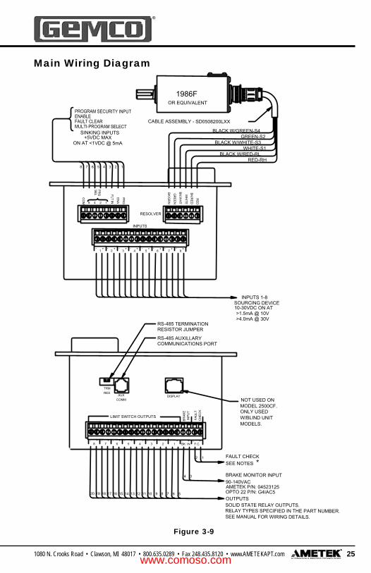
Figure 3-9
Main Wiring Diagram
LIMIT SWITCH OUTPUTS
COMMAUX DISPLAY
BRA
KEIN
PUT
FAU
LTC
HE
CK
RESTRM
3- -
+
8
+
7
++
-6 5
-
+
4- - -
+
-
+
2
+
1
4+
8-- +
7-+
6+
5-++ + --
32-+
1-
RESOLVER
INPUTS
SEL
4
FLT IN
PRG
EN
A
12
PR
G
CO
M 8
BK
/RE
D
RED
GR
EE
N
BK
/WH
T
WH
ITE
BK/G
RN
+
-
+
-BK F.C.IN
BLACK W/GREEN-S4GREEN-S2
WHITE-S1BLACK W/WHITE-S3
BLACK W/RED-RLRED-RH
NOT USED ONMODEL 2500CF.ONLY USEDW/BLIND UNITMODELS.
1986F
CABLE ASSEMBLY - SD0508200LXXMULTI-PROGRAM SELECT
SINKING INPUTS+5VDC MAX
ON AT <1VDC @ 5mA
INPUTS 1-8
>1.5mA @ 10V
SOURCING DEVICE10-30VDC ON AT
124 378 6 5
8 7 6 51516 14 1013 1112 9181920 17
SOLID STATE RELAY OUTPUTS.RELAY TYPES SPECIFIED IN THE PART NUMBER.SEE MANUAL FOR WIRING DETAILS.
OUTPUTS
>4.0mA @ 30V
2 1
34
FAULT CHECKSEE NOTES *
90-140VACBRAKE MONITOR INPUT
OPTO 22 P/N: G4IAC5AMETEK P/N: 04523125
OR EQUIV LENT
FAULT CLEAR ENABLEPROGRAM SECURITY INPUT
RESISTOR JUMPERRS-485 TERMINATION
COMMUNICATIONS PORTRS-485 AUXILLARY
A
www.comoso.com

26 1080 N. Crooks Road • Clawson, MI 48017 • 800.635.0289 • Fax 248.435.8120 • www.AMETEKAPT.com
MACHINE SHOULD BE WIRED SO THAT DE-ENERGIZING FAULT CHECK RELAY WILL IMMEDIATELY STOP MACHINE.
IF NO FAULT CHECK NEEDED-DO NOT CONNECT ANY WIRING TO FAULT CHECK INPUT (FLT IN) AND DO NOT WIRE FAULT CHECKRELAY INTO MACHINE RUN CIRCUIT.
NOTE: ALL SWITCHES CAN BE REPLACED BY AN OPEN COLLECTOR (CURRENT SINKING) DEVICE, CONNECTED SIMILAR TO ABOVE.
RECOMMENDED WIRING OF FAULT CHECK RELAY
(C)1
(NO)2
COM
8
(CLOSED)ENABLE
FLT IN
3
THE USE OF THE FAULT CHECK FEATURE IS OPTIONAL AND SHOULD BE WIRED TO THE PLS CIRCUITRY AS SHOWN BELOW ONLY IF IT IS REQUIRED. IF A CUSTOMER SUPPLIEDFAULT CHECK RESET SWITCH IS WIRED AS BELOW, AFTER A FAULT OCCURS, THE FAULT CHECK RELAY DE-ENERGIZES AND ALL OUTPUT RELAYS DE-ENERGIZE. AFTER THE FAULTIS CORRECTED AND THE CUSTOMER SUPPLIED RESET SWITCH IS OPENED (DISABLED) AND RECLOSED (ENABLED), THE FAULT CHECK RELAY WILL RE-ENERGIZE AND THE OUTPUTS WILL RESUME NORMAL OPERATION.
IF NO RUN/SECURITY PROGRAM IS NEEDED (ALWAYS IN PROGRAM MODE) INSTALL A JUMPER WIRE BETWEEN COM & PGM.ENABLE THE USE OF THE ENABLE FEATURE IS OPTIONAL AND SHOULD BE WIRED TO THE PLS CIRCUITRY AS SHOWN BELOW ONLY IF IT IS REQUIRED. TYPICAL WIRING FOR CUSTOMER SUPPLIED ENABLE INPUT. WHEN SWITCH IS OPEN, PLS OUTPUTS WILL BE ENABLED.WHEN SWITCH IS CLOSED OUTPUTS WILL BE DISABLED.
FAULT CHECK CIRCUIT
COM
8
RUNPROGRAM(CLOSED) PGM
1
OR
DISABLECOM
8 2
ENABLE(OPEN) ENA
OR
OR
TO MACHINERUN CONTROL
2500 PLS CANNOT BE PROGRAMMED UNTIL THE PGM INPUT HAS BEEN ACTUATED - CONTINUITY - BETWEEN COM & PGM INPUTPROGRAM SECURITY INPUTTYPICAL WIRING FOR CUSTOMER SUPPLIED PROGRAM SECURITY SWITCH WHEN SWITCH IS CLOSED, PLS CAN BE PLACED IN PROGRAM MODE.WHEN SWITCH IS OPEN, PLS WILL BE IN RUN MODE. (ALL FUNCTIONS CAN BE VIEWED BUT DATA CANNOT BE CHANGED.)TWO METHODS OF WIRING SECURITY SWITCH
SEE MANUAL FOR INPUT POWER WIRING DETAILS.
INPUT POWER
B) I/O MODULE AC OUTPUT 24-280 VAC
A) I/O MODULE DC OUTPUT 5-60 VDC
THIS DEVICE CAN BE SUPPLIED WITH THESE OUTPUT DEVICES:
PART No. 04523126
PART No. O4523127
CONNECTIONS TO P.C. OUTPUT MODULES
3
4
2
1
R
DC OUTPUT MODULE
AMETEK P/N: 04523126
AMPLIFIER
c
FUSE
OPTO 22 P/N: G4ODC5
OPTO 22 P/N: G4OAC5AAMETEK P/N: 04523127
LOAD
OR
LOAD
4
AC OUTPUT MODULE
3
2FUSE
1
CIRCUIT
cR
LOAD
LOAD
OR
VAC
ZERO VOLTAGE
LED
LED
CONTROLLEDINTERNALLYBY 2500 PLS
CONTROLLEDINTERNALLYBY 2500 PLS
*
*
* COMMUTATION DIODE MUST BE USED ON INDUCTIVELOADS. TYPICALLY, USE DIODE IN4005.
Drawing # E0238000
www.comoso.com

271080 N. Crooks Road • Clawson, MI 48017 • 800.635.0289 • Fax 248.435.8120 • www.AMETEKAPT.com
Enable / Disable Outputs
The use of the enable feature is optional and should be wired to the PLS circuitry as shown below only if it is required. Typical wiring for customer supplied
Figure 3 - 11
DISABLE
8
COM (OPEN)ENABLE
OR
ENA
2
PROGRAM SECURITY INPUT
ON AT <1VDC @ 5mA
MULTI-PROGRAM SELECT
- ++ - - +
PR
G
8
CO
M 4
SE
L
2 1
EN
A
PR
G
FLT IN
58 7 6 4 3 12
FAULT CLEAR
+5VDC MAXSINKING INPUTS
ENABLE
INPUTS
+- - -+ + -- + +
BK
/RE
D
RESOLVER
BK
/GR
N
WH
ITE
BK
/WH
T
GR
EE
N
RE
D
1 2 3 4 5 6 7 8
enable input. When the switch is open, PLS outputs will be enabled. When the switch is closed, outputs will be disabled.
www.comoso.com

28 1080 N. Crooks Road • Clawson, MI 48017 • 800.635.0289 • Fax 248.435.8120 • www.AMETEKAPT.com
Input Wiring Guidelines
• An external power supply must be used to power inputs.• Inputs will operate with voltages from 10 - 30VDC.• Each input will draw 4.0mA max.• A combination of mechanical and solid state devices can be used.• Each input is optically isolated.• With mechanical switches, you can either break to + or - input.• Each input is optically isolated and does not share a common.• Voltage must be present across + and - terminals for input to turn on.
- +8
+ -7
-6
+
Inputs Terminal Strip
4+-
5- -+
3+ -
2- +
1+
3 wire DC Sensor w/ PNP Output
+
Customer Supplied 10-30VDC
Power Supply-
Connect to + terminal of inputs 1-8
PLC Sourcing Module or other
Connect to + terminal of inputs 1-8
Connect to + terminal of inputs 1-8
Switch or Relay Contact
Whisker Sensor
Note: For whisker sensor applications take power supply + to + of input terminal & - of power supply to frame of machine.
Sourcing PNP Devices + VDC is being switched
Figure 3 - 12
Control Input Wiring
www.comoso.com

291080 N. Crooks Road • Clawson, MI 48017 • 800.635.0289 • Fax 248.435.8120 • www.AMETEKAPT.com
Outputs Terminal Strip
Across LS1-8 +,- outputs
Note: L1 or L2 can be broken with the solid state output relay.
AC OUTPUT24-280VAC 3 AMP MAX.
LIMIT SWITCH OUTPUTS
8
+
7
+
56
+
4
+ +
3
+- - +
12
+
INBK
+
INP
UT
BR
AK
E
F.C.
+
CH
EC
KFA
ULT
NeutralL2
HotL1
LoadLimit Switch Outputs 1-8
Load
DC OUTPUT5-60VAC 3 AMP MAX.
+VDC
DC Common
+
Sourcing
Load
DC Common
Sinking
+
+VDC*
*
Limit Switch Outputs 1-8
Figure 3 - 13
Figure 3 - 14
* Commutation diode must be used on inductive loadsTypically, use IN4005
LIMIT SWITCH OUTPUTS
8
+
7
+
56
+
RES
COMMAUX
TRM
4
+ +
3
+
- -
+
12
+
INBK
+
INP
UT
BR
AK
E
DISPLAY
F.C.
+
CH
EC
KFA
ULT
L1L2
Brake Input 90-140VAC from Presses Brake/Clutch Solenoid
Note: The Brake Monitor input looks for a loss of input voltage. When the brake monitor’s input voltage drops out, the 2500 starts a high speed counter. This counter continues to count until the resolvers comes to a stop.
Control Output Wiring
Brake Monitor Input Wiring
www.comoso.com

30 1080 N. Crooks Road • Clawson, MI 48017 • 800.635.0289 • Fax 248.435.8120 • www.AMETEKAPT.com
Clawson, MI 48017 U.S.A.NP0197900
R
ENTER
SCROLL
MENU
2500 SERIES PLS
Shift Key Left
Menu Key
2 x 24 Alpha Numeric:Vacuum Florescent Display.
POS 12345RPM 2000
Shift Key Right
Rotary Knob
Enter Key
Chapter 4: ProgrammingThis chapter provides detailed descriptions and instructions for programming all 2500 PLS functions. A complete list of functions, with a brief explanation, can be found in Chapter One: Standard Features.
Figure 4-1: Programming Keys
4.1 Main Controller Keypad
Figure 4-1 calls out the 2500’s display, rotary knob and programming keys. Following this fi gure are descriptions of these keys and how they work, as well as a short tutorial on how to use the keys and rotary knob.
www.comoso.com

311080 N. Crooks Road • Clawson, MI 48017 • 800.635.0289 • Fax 248.435.8120 • www.AMETEKAPT.com
MENU
SCROLL
ENTER
The Menu key is used to begin a process for programming a function. When this key is pressed, the 2500 prepares itself for entry of a specifi c function using the rotary knob.
The rotary knob is used to scroll through the 2500’s list of functions, as well as other lists. To scroll to a particular function, continue to turn the rotary knob (after selecting the Menu key) until the arrow in the upper left hand corner of the display is at the desired function. The rotary knob is also used to increment/decrement selected digits on the 2500’s display. Incrementing/decrementing digits can be done to select a value for a function. To move to a specifi ed digit on the display, use either the shift right or shift left keys. A cursor under the digit indicates it is activated to be incremented/decremented.
The shift left or right keys are used to move to a specifi c digit shown on the 2500’s display. To move to a specifi c digit on the display, press either shift left or shift right. A cursor under the digit indicates that digit is selected. (To increment/decrement that digit, turn the rotary knob). Continue with this process until the proper value is displayed.
The ENTER key is used for several purposes. For example, it is selected after a function number is displayed. This begins the programming process for the selected function. The ENTER key is also used to program a value in a function. This is done by selecting the enter key after the desired value is displayed on the screen.
The 2500 PLS has four keys and a rotary knob located on the front panel. These keys are used to program functions and perform basic operations.
4.2 Programming Keys Defi ned
www.comoso.com

32 1080 N. Crooks Road • Clawson, MI 48017 • 800.635.0289 • Fax 248.435.8120 • www.AMETEKAPT.com
A JUMPER WIRE BETWEEN COM & PGM.IF NO RUN/SECURITY PROGRAM IS NEEDED (ALWAYS IN PROGRAM MODE) INSTALL
TWO METHODS OF WIRING SECURITY SWITCH
COM
8
RUNPROGRAM(CLOSED) PGM
1OR
(See Figure 3-3 for connector location.)
4.3 Before You Start
Before confi guring or programming the 2500 PLS, the following must be done.
The 2500 PLS cannot be programmed until the PGM input has been actuated and continuity is between COM and PGM inputs.
Program Security InputTypical wiring for customer supplied program security switch. When switch is closed, the PLS can be placed in program mode. When switch is open, the PLS will be in run mode (all functions can be viewed but data cannot be changed).
Once the mechanical security input has been made, you will need to enter the user password before programming. The default user password is 2500. See Program mode access in Section 4.4 :Programming and Supervisory Mode Functions.
www.comoso.com

331080 N. Crooks Road • Clawson, MI 48017 • 800.635.0289 • Fax 248.435.8120 • www.AMETEKAPT.com
MENU
SCROLL
MENU SCROLL
4.4 Menu Tree
Main Menu FunctionsScale FactorOffsetSetpoint DataMin. Speed DisableLinear Speed CompensationTime-Based OutputsInput Confi gurationSave Input PositionBrake MonitorMotion DetectSoftware VersionSelect ProgramCustomize Decimal Pt.Supervisors Menu
Supervisor Menu FunctionsCustomize DisplayDefi ne Supv. PasswordDefi ne User PasswordDefi ne Title ScreenSet Fault Clear OptionEnable Brake InputLockout FunctionsInitialize SystemInitialize ProgramLabel OutputsLabel InputsExpansion Boards
Password
NOTE: The programming examples listed throughout this manual will show where the function is located in the Menu Tree.
4.5 User and Supervisor Mode Access
This section provides descriptions and instructions for user and supervision mode functions. These functions are used to put the controller in either user or supervisor mode. Before a function can be programmed, the controller must be in the program mode. This is done through the User Mode Access Function, which is the fi rst function described in this section. The controller can also be put in the Supervisor Menu. Putting the controller in this mode allows supervisor functions to be programmed. Putting the controller in this mode is described in Supervisor Mode Access Functions. The following is a list of the program and supervisor functions.
www.comoso.com

34 1080 N. Crooks Road • Clawson, MI 48017 • 800.635.0289 • Fax 248.435.8120 • www.AMETEKAPT.com
Main Menu FunctionsScale FactorOffsetSetpoint DataMin. Speed DisableLinear Speed CompensationTime-Based OutputsInput Confi gurationSave Input PositionBrake MonitorMotion DetectSoftware VersionSelect ProgramCustomize Decimal Pt.Supervisors Menu
User Mode AccessThe User Mode Access function is used to put the controller in the program mode. Only when the controller is in the program mode can functions be programmed.
A user mode access code must be entered in order to put the controller in the program mode. The factory default user password is 2500, this value can be changed via the supervisor menu. See Defi ne User Password.
When programming functions, the controller will prompt you for the password. This is done in two parts. First the Program Security Input must have continuity from pin 8 (com) to pin 1 (prg) as shown in Section 4:3. If there is not continuity, the display will show KEY NOT IN THE PROGRAM MODE. The second step entering the user password, is done through the keypad and rotary knob, as described in Section 4:2.
The display will show:
- PASSWORD PROTECTED - ENTER PASSWORD: 0000
Supervisor Menu FunctionsCustomize DisplayDefi ne Supv. PasswordDefi ne User PasswordDefi ne Title ScreenSet Fault Clear OptionEnable Brake InputLockout FunctionsInitialize SystemInitialize ProgramLabel OutputsLabel InputsExpansion Boards
Supervisor Mode AccessThe Supervisor Mode Access function is used to put the controller in the supervisor mode. Only when the controller is in the program or supervisor mode can the supervisor functions be programmed.
A supervisor mode password must be entered in order to put the controller in the supervisor mode. The factory default supervisor password is 9999, this value can be changed via the supervisor menu (see Defi ne Supervisor Password).
When accessing supervisor functions, the controller will prompt you to enter your supervisor password. (See Section 4.2 for a description. Again, the Program Security Input must be connected properly. See Section 4.3 for specifi cs.)
The display will show:
- LIMITED ACCESS ENTER SUPV. CODE: 0000
www.comoso.com

351080 N. Crooks Road • Clawson, MI 48017 • 800.635.0289 • Fax 248.435.8120 • www.AMETEKAPT.com
Global parameters are those variables that are normally programmed only when the system is initially installed. This chapter contains instructions for programming these parameters. You may fi nd that some of these parameters are not necessary or are already defaulted to your desired setting. In these cases, you will not need to make any adjustments.
The following settings are detailed in this chapter:
• Initialize System • Expansion Boards • Lockout Functions • Scale Factor • Decimal Location • Offset • Motion Detect • Brake Monitor • Set Fault Clear Option • Customizing Display • Defi ne Title Screen • Label Outputs • Label Inputs • Defi ne User Password • Defi ne Supervisor Password • Software Version
NOTE: The controller can only be programmed when the security input is closed and either the user or supervisor access code has been entered. See Chapter 4 Programming for details.
5.1 Quick Start
In many simple applications it is not necessary to program all of the 2500 functions. For a quick start, or to become familiar with the programming process, attach the incoming power, wire the pre-assembled resolver cable, and jumper the program input to the appropriate terminals on the controller. See Chapter 3 for wiring details. Then program the following functions in this order:
1. Scale Factor - See Section 5.52. Offset - See Section 5.73. Setpoint Data - See Section 6.1
This completes the quick start programming process.
Chapter 5: Global Parameters
www.comoso.com

36 1080 N. Crooks Road • Clawson, MI 48017 • 800.635.0289 • Fax 248.435.8120 • www.AMETEKAPT.com
5.2 Initialize System
The Initialize System function presets all of the controller’s calibration setting to factory defaults and deletes any programming that may be stored in the controller, except for the user and supervisor passwords.
Due to factory testing, there may be some data programmed into your controller. Because of this, it is recommended that you initialize the controller upon receiving it from the factory. To initialize the controller, perform the following steps:
Step 1
To program the 2500 PLS, press the MENU button then rotate the rotary knob to scroll through the menu driven display until the is in front of Supervisor Menu. Press ENTER. The controller will prompt you to enter the supervisor password. (See Chapter 4, Programming for password details).
Rotate knob until the is in front of INITIALIZE SYSTEM, then press ENTER. The display will show INITIALIZING WILL DELETE ALL DATA. CONTINUE?. Rotate knob to YES, then press ENTER.
Main DisplayPosition: 1.234RPM: 0
Supervisor Menu FunctionsCustomize DisplayDefi ne Supv. PasswordDefi ne User PasswordDefi ne Title ScreenSet Fault Clear OptionEnable Brake InputLockout FunctionsInitialize SystemInitialize ProgramLabel OutputsLabel InputsExpansion Boards
Step 2
If you answer YES to reinitialize, the unit will ask you to re-verify your password, once you enter your supervisor password the display will show, SYSTEM INITIALIZATION IN PROCESS… PLEASE WAIT.
This procedure will take a few minutes to complete.
Step 3
To escape Initialize System programming screen, either press ENTER to accept or MENU to back up one screen.
www.comoso.com
371080 N. Crooks Road • Clawson, MI 48017 • 800.635.0289 • Fax 248.435.8120 • www.AMETEKAPT.com
Main DisplayPosition: 1.234RPM: 0
Supervisor Menu FunctionsCustomize DisplayDefi ne Supv. PasswordDefi ne User PasswordDefi ne Title ScreenSet Fault Clear OptionEnable Brake InputLockout FunctionsInitialize SystemInitialize ProgramLabel OutputsLabel InputsExpansion Boards
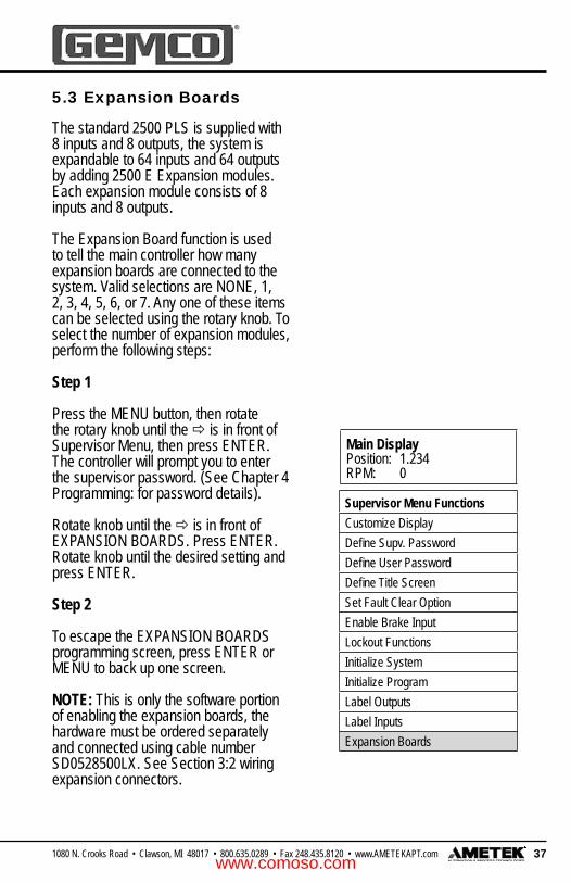
5.3 Expansion Boards
The standard 2500 PLS is supplied with 8 inputs and 8 outputs, the system is expandable to 64 inputs and 64 outputs by adding 2500 E Expansion modules. Each expansion module consists of 8 inputs and 8 outputs.
The Expansion Board function is used to tell the main controller how many expansion boards are connected to the system. Valid selections are NONE, 1, 2, 3, 4, 5, 6, or 7. Any one of these items can be selected using the rotary knob. To select the number of expansion modules, perform the following steps:
Step 1
Press the MENU button, then rotate the rotary knob until the is in front of Supervisor Menu, then press ENTER. The controller will prompt you to enter the supervisor password. (See Chapter 4 Programming: for password details).
Rotate knob until the is in front of EXPANSION BOARDS. Press ENTER.Rotate knob until the desired setting and press ENTER.
Step 2
To escape the EXPANSION BOARDS programming screen, press ENTER or MENU to back up one screen.
NOTE: This is only the software portion of enabling the expansion boards, the hardware must be ordered separately and connected using cable number SD0528500LX. See Section 3:2 wiring expansion connectors.
www.comoso.com

38 1080 N. Crooks Road • Clawson, MI 48017 • 800.635.0289 • Fax 248.435.8120 • www.AMETEKAPT.com
Main DisplayPosition: 1.234RPM: 0
Supervisor Menu FunctionsCustomize DisplayDefi ne Supv. PasswordDefi ne User PasswordDefi ne Title ScreenSet Fault Clear OptionEnable Brake InputLockout FunctionsInitialize SystemInitialize ProgramLabel OutputsLabel InputsExpansion Boards
5.4 Lockout Functions
The Lockout function allows you to program a four digit password into the 2500 PLS so that, without entering the supervisors password, certain programmed parameters such as Scale Factor, Output Channels, Offset, Minimum Speed, Linear Speed Compensation, Inputs, Brake Monitor, Brake Relay, Motion Detect, Program Select, and Decimal Point, cannot be accessed. This provides additional security when used with the user password. To program this additional security, fi rst select and lock the parameters you wish to protect. Once these parameters are locked they cannot be changed without fi rst entering the supervisors access code. To access the lockout functions, perform the following steps:
Step 1
Press the MENU button, then rotate the rotary knob until the is in front of Supervisor Menu. Press ENTER. Enter the supervisor password. (See Chapter 4 Programming: for password details).
Rotate knob until the is in front of LOCKOUT FUNCTIONS. Press ENTER.Rotate knob until the is in front of the desired lockout setting and press ENTER. The display will change from unlocked to locked, or locked to unlocked. Rotate knob until the is in front of the next desired lockout setting and press ENTER. Continue until all desired setting are locked or unlocked, then press MENU to escape.
Step 2
To escape the LOCKOUT FUNCTIONS programming screen, press ENTER or MENU to back up one screen.
NOTE: Any individual Input or Output Channel can be locked.
If a function has been locked and the user tries to access it, the display will show LIMITED ACCESS/FUNCTION HAS BEEN LOCKED. If this message is displayed, simply press MENU to back up one screen and enter the supervisors access code. (See Chapter 4: Users and Supervisors Mode Access)
www.comoso.com

391080 N. Crooks Road • Clawson, MI 48017 • 800.635.0289 • Fax 248.435.8120 • www.AMETEKAPT.com
Main DisplayPosition: 1.234RPM: 0
Main Menu FunctionsScale FactorOffsetSetpoint DataMin. Speed DisableLinear Speed CompensationTime-Based OutputsInput Confi gurationSave Input PositionBrake MonitorMotion DetectSoftware VersionSelect ProgramCustomize Decimal Pt.Supervisors Menu
5.5 Scale Factor
The scale factor can be programmed to display any engineering unit. For example, one rotation of the resolver could represent one product moving through the machine. The length of the product could then be programmed as the scale factor and setpoints can then be programmed in the length units that represent where they occur along the product. Valid scale factors can be from 2 - 65535. The 2500 has a 12 bit resolver to digital converter, which means it can count by ones, up to a scale factor value of 4096. For scale factors above 4096, the 2500 will not count by ones. Setting the scale factor will erase any existing setpoint data. For this reason, programming the scale factor should be done before any other programming. To program the scale factor, perform the following steps:
Step 1
Press the MENU button, then rotate the rotary knob until the is in front of scale factor, then press ENTER.
Step 2
Rotate knob to EDIT and press ENTER.The controller will prompt you to enter the users password. See Chapter 4 Programming: for password details.
Rotate knob to increase / decrease numerical values. Use keys to move cursor to next digit, until the displayed value is the desired new Scale Factor, press ENTER.
Step 3
To escape the Scale Factor programming screen, either press MENU to back up one screen or rotate knob to EXIT and then press ENTER.
Help Screens are located in each menu. To access, rotate rotary knob to HELP and press ENTER. Use rotary knob to scroll through help screens. To exit HELP screens, press MENU or ENTER.
www.comoso.com

40 1080 N. Crooks Road • Clawson, MI 48017 • 800.635.0289 • Fax 248.435.8120 • www.AMETEKAPT.com
Main DisplayPosition: 1.234RPM: 0
Main Menu FunctionsScale FactorOffsetSetpoint DataMin. Speed DisableLinear Speed CompensationTime-Based OutputsInput Confi gurationSave Input PositionBrake MonitorMotion DetectSoftware VersionSelect ProgramCustomize Decimal Pt.Supervisors Menu
5.6 Customize Decimal Pt. (Decimal Location)
The Customize Decimal Point function is used to program the resolution of the 2500 PLS and all positional data shown on the display. Resolution can either be displayed in whole units, tenths, hundredths, or thousandths. For programming see example below.
Step 1
Press the MENU button, then rotate the rotary knob until the is in front of Customize Decimal Point, then press ENTER.
Step 2
Rotate knob to EDIT and press ENTER. The controller will prompt you to enter the users password (See Chapter 4 Programming: for password details).Rotate knob to increase / decrease decimal location or use keys to move decimal to next digit, until the displayed value is the desired new Decimal Position, then press ENTER.
Step 3
To escape the Decimal Point programming screen, either press MENU to back up one screen or rotate knob to EXIT and then press ENTER.
Help Screens are located in each menu. To access, rotate rotary knob to HELP and press ENTER, Use rotary knob to scroll through help screen. To exit HELP screens press MENU or ENTER.
www.comoso.com

411080 N. Crooks Road • Clawson, MI 48017 • 800.635.0289 • Fax 248.435.8120 • www.AMETEKAPT.com
Main DisplayPosition: 1.234RPM: 0
Main Menu FunctionsScale FactorOffsetSetpoint DataMin. Speed DisableLinear Speed CompensationTime-Based OutputsInput Confi gurationSave Input PositionBrake MonitorMotion DetectSoftware VersionSelect ProgramCustomize Decimal Pt.Supervisors Menu
5.7 Electronic Offset
The offset feature is used to synchronize the digital display with the actual machine position. The 2500 PLS has full scale factor offset capabilites, and the offset is held in nonvolatile memory. However, to eliminate possible problems in the event that a replacement PLS is required, it is good practice to mechanically synchronize the resolver with the machine and then use the offset feature to make fi nal, fi ne tune adjustments. Valid offset ranges are 0 to [1 less than the programmed scale factor]. To offset the controller, perform the following steps:
Step 1
Press the MENU button, then rotate the rotary knob until the is in front of Offset, then press ENTER.
Step 2
Rotate knob to EDIT and press ENTER.The controller will prompt you to enter the users password. See Chapter 4 Programming: for password details.Rotate knob to increase / decrease numerical values.Use keys to move cursor to next digit, until the displayed value is the desired New Position Value, press ENTER.
Step 3
To escape the Offset programming screen, either press MENU to back up one screen or rotate knob to EXIT and then press ENTER.
Help Screens are located in each menu. To access, rotate rotary knob to HELP and press ENTER. Use rotary knob to scroll through help screen. To exit HELP screens press MENU or ENTER.
www.comoso.com

42 1080 N. Crooks Road • Clawson, MI 48017 • 800.635.0289 • Fax 248.435.8120 • www.AMETEKAPT.com
Main DisplayPosition: 1.234RPM: 0
Main Menu FunctionsScale FactorOffsetSetpoint DataMin. Speed DisableLinear Speed CompensationTime-Based OutputsInput Confi gurationSave Input PositionBrake MonitorMotion DetectSoftware VersionSelect ProgramCustomize Decimal Pt.Supervisors Menu
5.8 Motion Detect
Any one of the 64 limit switch output channels can be confi gured to operate as a motion detect output. This output will energize upon reaching a programmed RPM value and will de-energize as RPM drops below the selected RPM value. Typical uses for this feature include latching in a machine operation when a desired operating speed is reached or for detecting a broken coupling or chain driving the resolver. To select a circuit for motion detect, perform the following steps:
Step 1
Press the MENU button, then rotate the rotary knob until the is in front of Motion Detect, then press ENTER.
Step 2
Rotate knob to EDIT, press ENTER.The controller will prompt you to enter the users password. (See Chapter 4 Programming: for password details.)Rotate knob to increase / decrease New Motion Detect Relay, press ENTER.The controller will prompt you to enter the New Motion Detect Value.Rotate knob to increase / decrease numerical values. Use keys to move cursor to next digit, until the displayed value is the desired New Motion Detect RPM Value, press ENTER.
Step 3
To escape Motion Detect programming screen, either press MENU to back up one screen or rotate knob to EXIT and then press ENTER.
Help Screens are located in each menu. To access, rotate rotary knob to HELP and press ENTER. Use rotary knob to scroll through help screen. To exit HELP screens press MENU or ENTER.
www.comoso.com

431080 N. Crooks Road • Clawson, MI 48017 • 800.635.0289 • Fax 248.435.8120 • www.AMETEKAPT.com
Main DisplayPosition: 1.234RPM: 0
Supervisor Menu FunctionsCustomize DisplayDefi ne Supv. PasswordDefi ne User PasswordDefi ne Title ScreenSet Fault Clear OptionEnable Brake InputLockout FunctionsInitialize SystemInitialize ProgramLabel OutputsLabel InputsExpansion Boards
5.9 Enable Brake Input
The Enable Brake Input function is used to enable or disable the Brake monitor. Valid selections are enabled or disabled. Using the rotary knob you can scroll through the displayed settings. For Brake monitoring details see Section 5.10 and Section 12. To enable or disable the brake monitor, perform the following steps:
Step 1
Press the MENU button, then rotate the rotary knob until the is in front of Supervisor Menu, press ENTER. The controller will prompt you to enter the supervisor password. (See Chapter 4 Programming: for password details.)Rotate knob until the is in front of ENABLE BRAKE INPUT, press ENTER.Rotate knob until desired setting is displayed, press ENTER.
Step 2
To escape ENABLE BRAKE INPUT programming screen, press ENTER or MENU to back up one screen.
5.10 Brake Monitor
Any one of the 64 limit switch output channels can be confi gured to operate as a Brake Monitor output. The Brake monitor offers an on-line monitor which checks the stopping time of the machine against a customer selected preset stopping time in milli-seconds, and can be used to check the stopping distance at any point during the machine’s operation.
The stopping time and stopping degrees can be viewed from the main display by rotating the rotary dial. The Brake monitor calculates stopping time by monitoring the time span between the clutch disengagement and the press coming to a complete stop.
The system begins this timing sequence when it sees the loss of voltage from the brake monitor’s input, wired between input terminals 3 and 4 (See Fig. 3-14 for wiring details).
NOTE: This feature is typically only used in the stamping industry to measure the stopping time of a stamping press.
www.comoso.com

44 1080 N. Crooks Road • Clawson, MI 48017 • 800.635.0289 • Fax 248.435.8120 • www.AMETEKAPT.com
The input of the Brake monitor input relay must be off when the clutch disengages. In efforts to make the brake monitor fail safe, if the controller sees motion without seeing the brake input, a break input error will occur. For brake monitor programming, perform the following steps:
Step 1
To program the 2500 PLS, press the MENU button then rotate the rotary knob to scroll through the menu driven display until the is in front of Brake Monitor, then press ENTER.
Step 2
The brake monitor feature is disabled when shipped from the factory. To enable the brake monitor feature, go to the Supervisor Menu and enable the Brake monitor feature, press MENU button twice to return to the main programming Brake Monitoring screen. The display will show Brake Time / Brake Relay. Rotate knob until is in front of desired setting, press ENTER. Rotate knob to EDIT, press ENTER. The controller will prompt you to enter the users password. (See Chapter 4 Programming: for password details.)
Brake TimeThe controller will prompt you to enter New Brake Warning Time. Rotate knob to increase / decrease numerical values. Use keys to move cursor to next digit, until the displayed value is the desired New Brake Warning Time, press ENTER. The controller will prompt you to enter New Brake Error Time. Rotate knob to increase / decrease numerical values. Use keys to move cursor
Main DisplayPosition: 1.234RPM: 0
Main Menu FunctionsScale FactorOffsetSetpoint DataMin. Speed DisableLinear Speed CompensationTime-Based OutputsInput Confi gurationSave Input PositionBrake MonitorMotion DetectSoftware VersionSelect ProgramCustomize Decimal Pt.Supervisors Menu
to next digit, until the displayed value is the desired New Brake Error Time, press ENTER.
Brake RelayRotate knob until is in front of Brake Relay, press ENTER. Rotate knob to EDIT, press ENTER.
The controller will prompt you to enter New Brake Relay Channel Rotate knob to increase / decrease numerical values, until the displayed value is the desired New Brake Relay Channel, press ENTER.
Step 3
To escape Brake Monitor programming screen, either press MENU to back up one screen or rotate knob to EXIT and then press ENTER.
www.comoso.com

451080 N. Crooks Road • Clawson, MI 48017 • 800.635.0289 • Fax 248.435.8120 • www.AMETEKAPT.com
Main DisplayPosition: 1.234RPM: 0
Supervisor Menu FunctionsCustomize DisplayDefi ne Supv. PasswordDefi ne User PasswordDefi ne Title ScreenSet Fault Clear OptionEnable Brake InputLockout FunctionsInitialize SystemInitialize ProgramLabel OutputsLabel InputsExpansion Boards
The SET FAULT CLEAR OPTION feature is used to select how faults are to be cleared from the controller. The factory default setting is that pressing the ENTER key will clear faults. The three choices are 1) only from the keypad, 2) only from the fault reset input, or 3) either the keypad or fault reset input (see fi gure 3-4 for wiring details). See Chapter 12 for a complete explanation on faults.
• FAULTS CLEARED WITH ENTER KEY = when a fault is detected the display will show you the type of error, press the ENTER key to clear the fault.
• FAULTS CLEARED WITH INPUT PIN = when a fault is detected the display will show you the type of error, cycle the fault reset input to clear the fault.
• FAULTS CLEARED WITH ENTER KEY or INPUT PIN = when a fault is detected the display will show you the type of error, either press the ENTER key or cycle the fault reset input to clear the fault.
To set the fault clear option, perform the following steps:
Step 1
To program the 2500 PLS, press the MENU button then rotate the rotary knob to scroll through the menu driven display until the is in front of Supervisor
Menu, press ENTER. The controller will prompt you to enter the supervisor password. (See Chapter 4 Programming: for password details.)
Rotate knob until the is in front of SET FAULT CLEAR OPTION, press ENTER Using the rotary knob to scroll through the selections, until the desired method is displayed, press ENTER.
Step 2
To escape SET FAULT CLEAR OPTION programming screen, press ENTER or MENU to back up one screen.
5.11 Set Fault Clear Option
www.comoso.com

46 1080 N. Crooks Road • Clawson, MI 48017 • 800.635.0289 • Fax 248.435.8120 • www.AMETEKAPT.com
Main DisplayPosition: 1.234RPM: 0
Supervisor Menu FunctionsCustomize DisplayDefi ne Supv. PasswordDefi ne User PasswordDefi ne Title ScreenSet Fault Clear OptionEnable Brake InputLockout FunctionsInitialize SystemInitialize ProgramLabel OutputsLabel InputsExpansion Boards
5.12 Customize Display
The customize display function is used to determine what will be shown on the display during machine operation. Valid selections are position data (this selection will display both position and RPM), brake data (this selection will show both stopping time and stopping degrees), and program data (this selection will show you the active running program). Any one or all three of the items can be selected. Using the rotary knob you can scroll through the displayed settings. To customize the display, perform the following steps:
Step 1
To program the 2500 PLS, press the MENU button then rotate the rotary knob to scroll through the menu driven display until the is in front of Supervisor Menu, press ENTER. The controller will prompt you to enter the supervisor password. (See Chapter 4 Programming: for password details.)
Rotate knob until the is in front of CUSTOMIZE DISPLAY, press ENTER.Rotate knob until the is in front of the desired setting and press ENTER to show or hide this data.
Step 2
To escape the Customize Display programming screen, press MENU to back up one screen.
NOTE: If all three settings are hidden, the display will continuously show what message is set in DEFINE TITLE SCREENS.
www.comoso.com
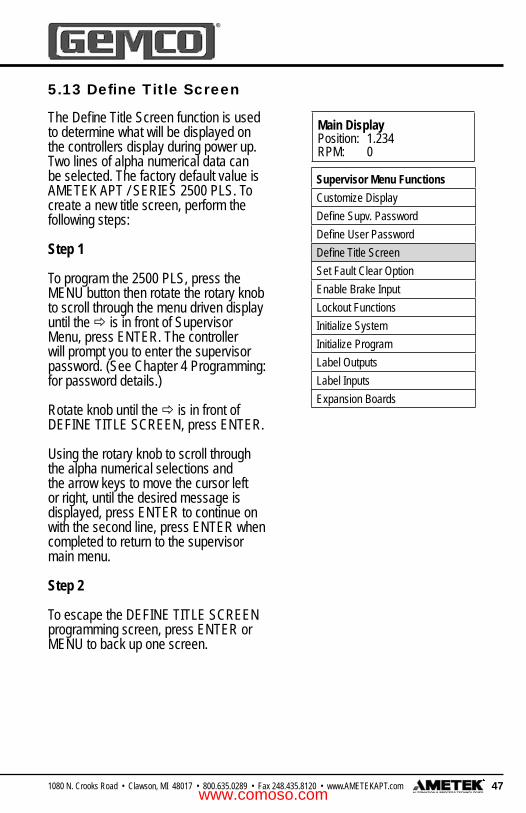
471080 N. Crooks Road • Clawson, MI 48017 • 800.635.0289 • Fax 248.435.8120 • www.AMETEKAPT.com
Main DisplayPosition: 1.234RPM: 0
Supervisor Menu FunctionsCustomize DisplayDefi ne Supv. PasswordDefi ne User PasswordDefi ne Title ScreenSet Fault Clear OptionEnable Brake InputLockout FunctionsInitialize SystemInitialize ProgramLabel OutputsLabel InputsExpansion Boards
5.13 Defi ne Title Screen
The Defi ne Title Screen function is used to determine what will be displayed on the controllers display during power up. Two lines of alpha numerical data can be selected. The factory default value is AMETEK APT / SERIES 2500 PLS. To create a new title screen, perform the following steps:
Step 1
To program the 2500 PLS, press the MENU button then rotate the rotary knob to scroll through the menu driven display until the is in front of Supervisor Menu, press ENTER. The controller will prompt you to enter the supervisor password. (See Chapter 4 Programming: for password details.)
Rotate knob until the is in front of DEFINE TITLE SCREEN, press ENTER.
Using the rotary knob to scroll through the alpha numerical selections and the arrow keys to move the cursor left or right, until the desired message is displayed, press ENTER to continue on with the second line, press ENTER when completed to return to the supervisor main menu.
Step 2
To escape the DEFINE TITLE SCREEN programming screen, press ENTER or MENU to back up one screen.
www.comoso.com

48 1080 N. Crooks Road • Clawson, MI 48017 • 800.635.0289 • Fax 248.435.8120 • www.AMETEKAPT.com
Main DisplayPosition: 1.234RPM: 0
Supervisor Menu FunctionsCustomize DisplayDefi ne Supv. PasswordDefi ne User PasswordDefi ne Title ScreenSet Fault Clear OptionEnable Brake InputLockout FunctionsInitialize SystemInitialize ProgramLabel OutputsLabel InputsExpansion Boards
5.14 Label Outputs
The Label Outputs function is used to customize the limit switch outputs to have alpha numeric names instead of the standard LS1- LS64 name. These names are a global parameter and will be the same for all programs. This feature allows the naming of individual outputs. For example, if output #5 is fi ring an adhesive gun, that output can be named ‘Upper Glue Gun’ or anything else that helps users understand the PLS and it’s processes. To label outputs, perform the following steps:
Step 1
To program the 2500 PLS, press the MENU button then rotate the rotary knob to scroll through the menu driven display until the is in front of Supervisor Menu, press ENTER. The controller will prompt you to enter the supervisor password. (See Chapter 4 Programming: for password details.)
Rotate knob until the is in front of LABEL OUTPUTS, press ENTER Using the rotary knob to scroll to the output channel you wish to name, press ENTER, the display will show ENTER NEW OUTPUT NAME.
Using the rotary knob to scroll through the alpha numerical selections and the arrow keys to move the cursor left or right, until the desired output name is displayed, press ENTER. Follow the same procedure to name all of the available outputs.
Step 2
To escape the LABEL OUTPUTS programming screen, press ENTER or MENU to back up one screen.
www.comoso.com

491080 N. Crooks Road • Clawson, MI 48017 • 800.635.0289 • Fax 248.435.8120 • www.AMETEKAPT.com
Main DisplayPosition: 1.234RPM: 0
Supervisor Menu FunctionsCustomize DisplayDefi ne Supv. PasswordDefi ne User PasswordDefi ne Title ScreenSet Fault Clear OptionEnable Brake InputLockout FunctionsInitialize SystemInitialize ProgramLabel OutputsLabel InputsExpansion Boards
5.15 Label Inputs
The Label Inputs function is used to customize the limit switch inputs to have alpha numeric names instead of the standard Input 1 - Input 64 name. These names are a global parameter and will be the same for all programs. This feature allows inputs to be named in the same fashion as outputs. See Section 5.14 for further details. To label inputs, perform the following steps:
Step 1
To program the 2500 PLS, press the MENU button then rotate the rotary knob to scroll through the menu driven display until the is in front of Supervisor Menu, press ENTER. The controller will prompt you to enter the supervisor password. (See Chapter 4 Programming: for password details.)
Rotate knob until the is in front of LABEL INPUTS, press ENTER Using the rotary knob to scroll to the input channel you wish to name, press ENTER, the display will show ENTER NEW INPUT NAME.
Using the rotary knob to scroll through the alpha numerical selections and the arrow keys to move the cursor left or right, until the desired input name is displayed, press ENTER. Follow the same procedure to name all of the available inputs.
Step 2
To escape the LABEL INPUTS programming screen, press ENTER or MENU to back up one screen.
www.comoso.com

50 1080 N. Crooks Road • Clawson, MI 48017 • 800.635.0289 • Fax 248.435.8120 • www.AMETEKAPT.com
5.16 Defi ne User Password
The Defi ne User Password function is used to change the current users mode access code. The factory default access code is 2500. Values from 0000 to 9999 can be used for an access code. To program this function, the controller must be in the supervisor mode. (For more information, see User Mode Access.) To create a new user access code, perform the following steps:
Step 1
To program the 2500 PLS, press the MENU button then rotate the rotary knob to scroll through the menu driven display until the is in front of Supervisor Menu, press ENTER. The controller will prompt you to enter the supervisor password. (See Chapter 4 Programming: for password details.)
Rotate knob until the is in front of DEFINE USER PASSWORD, press ENTER .
Using the rotary knob to scroll through the numerical selections and the arrow keys to move the cursor left or right, until the desired password is displayed, press ENTER. The controller will now prompt you to VERIFY YOUR NEW USER ACCESS CODE. Re-enter the same value as above, then press ENTER.
Step 2
To escape the DEFINE USER PASSWORD programming screen, press ENTER or MENU to back up one screen.
Main DisplayPosition: 1.234RPM: 0
Supervisor Menu FunctionsCustomize DisplayDefi ne Supv. PasswordDefi ne User PasswordDefi ne Title ScreenSet Fault Clear OptionEnable Brake InputLockout FunctionsInitialize SystemInitialize ProgramLabel OutputsLabel InputsExpansion Boards
www.comoso.com
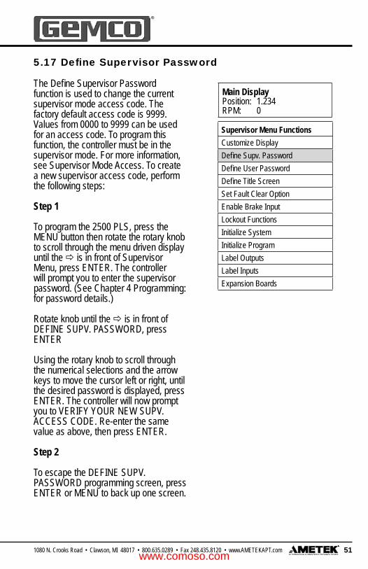
511080 N. Crooks Road • Clawson, MI 48017 • 800.635.0289 • Fax 248.435.8120 • www.AMETEKAPT.com
The Defi ne Supervisor Password function is used to change the current supervisor mode access code. The factory default access code is 9999. Values from 0000 to 9999 can be used for an access code. To program this function, the controller must be in the supervisor mode. For more information, see Supervisor Mode Access. To create a new supervisor access code, perform the following steps:
Step 1
To program the 2500 PLS, press the MENU button then rotate the rotary knob to scroll through the menu driven display until the is in front of Supervisor Menu, press ENTER. The controller will prompt you to enter the supervisor password. (See Chapter 4 Programming: for password details.)
Rotate knob until the is in front of DEFINE SUPV. PASSWORD, press ENTER
Using the rotary knob to scroll through the numerical selections and the arrow keys to move the cursor left or right, until the desired password is displayed, press ENTER. The controller will now prompt you to VERIFY YOUR NEW SUPV. ACCESS CODE. Re-enter the same value as above, then press ENTER.
Step 2
To escape the DEFINE SUPV. PASSWORD programming screen, press ENTER or MENU to back up one screen.
5.17 Defi ne Supervisor Password
Main DisplayPosition: 1.234RPM: 0
Supervisor Menu FunctionsCustomize DisplayDefi ne Supv. PasswordDefi ne User PasswordDefi ne Title ScreenSet Fault Clear OptionEnable Brake InputLockout FunctionsInitialize SystemInitialize ProgramLabel OutputsLabel InputsExpansion Boards
www.comoso.com

52 1080 N. Crooks Road • Clawson, MI 48017 • 800.635.0289 • Fax 248.435.8120 • www.AMETEKAPT.com
Main DisplayPosition: 1.234RPM: 0
Main Menu FunctionsScale FactorOffsetSetpoint DataMin. Speed DisableLinear Speed CompensationTime-Based OutputsInput Confi gurationSave Input PositionBrake MonitorMotion DetectSoftware VersionSelect ProgramCustomize Decimal Pt.Supervisors Menu
5.18 Software Version
The Software Version screen displays the version number of the fi rmware contained within the controller. This information may be useful if the unit needs to be returned for service. There are no values that can be programmed for this function.
Step 1
To program the 2500 PLS, press the MENU button then rotate the rotary knob to scroll through the menu driven display until the is in front of function desired, press ENTER.
Display shows:AMETEK APTSOFTWARE VERSION PX.XX
Step 2
To escape Software Version screen, press MENU to back up one screen.
www.comoso.com

531080 N. Crooks Road • Clawson, MI 48017 • 800.635.0289 • Fax 248.435.8120 • www.AMETEKAPT.com
0
270
180
90
Limit Switch #1 Energized
0
270
180
90
Limit Switch #1 Energized
Limit Switch #1 Energized
Limit Switch #1 Energized
Chapter 6: Limit Switch Outputs
There are eight limit switch outputs installed on the main controller and eight limit switch outputs on each and every expansion module. Setpoints are the on/off position at which the limit switch outputs operate as the resolver turns through one rotation.
All 64 channels can be programmed for up to six on/off dwells each (referred to as Setpoint pairs), over each rotation of the resolver. Each limit can be confi gured as either a Standard Channel, Time-Based Channel or Linear Speed Channel. To select output for Linear Speed or Time Based, refer to Linear Speed or Time Based instructions.
Programming Based on the Resolver’s Scale Factor
Programming a limit switch is based on the resolver’s scale factor. For example, assume the 2500 PLS is set for a 360° scale factor. If you programmed limit switch 1 to energize at 180° and de-energize at 270°, limit switch 1 would energize as shown in fi gure 6-1. The shaded area represents the area of the machine cycle where the limit switch is energized. Figure 6-2: Multiple Dwells
Figure 6-1: Programmed Limit Switch Based on a 360° Scale Factor
Multiple Dwells
Programmable limit switch outputs offer a unique function, which normal rotation cam limits cannot. Namely, the ability to turn a limit on and off more than once in a 360° cycle.
The 2500 PLS has the ability to store up to six dwells (dwell on and dwell off positions) per limit switch output. As a result, a limit switch can become energized and de-energized more than once in one rotation of the resolver. Figure 6-2 illustrates a limit switch becoming energized from 20-80°, 100-180°, and 200-270°.
www.comoso.com
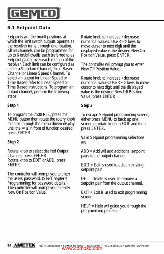
54 1080 N. Crooks Road • Clawson, MI 48017 • 800.635.0289 • Fax 248.435.8120 • www.AMETEKAPT.com
6.1 Setpoint Data
Setpoints are the on/off positions at which the limit switch outputs operate as the resolver turns through one rotation. All 64 channels can be programmed for up to 6 on/off dwells each (referred to as Setpoint pairs), over each rotation of the resolver. Each limit can be confi gured as either a Standard Channel, Time-Based Channel or Linear Speed Channel. To select an output for Linear Speed or Time Based refer to Linear Speed or Time Based instructions. To program an output channel, perform the following steps:
Step 1
To program the 2500 PLS, press the MENU button then rotate the rotary knob to scroll through the menu driven display until the is in front of function desired, press ENTER.
Step 2
Rotate knob to select desired Output Channel, press ENTER.Rotate knob to EDIT or ADD, press ENTER.
The controller will prompt you to enter the users password. (See Chapter 4 Programming: for password details.)The controller will prompt you to enter New On Position Value.
Rotate knob to increase / decrease numerical values. Use keys to move cursor to next digit until the displayed value is the desired New On Position Value, press ENTER.
The controller will prompt you to enter New Off Position Value.
Rotate knob to increase / decrease numerical values.Use keys to move cursor to next digit until the displayed value is the desired New Off Position Value, press ENTER.
Step 3
To escape Setpoint programming screen, either press MENU to back up one screen or rotate knob to EXIT and then press ENTER.
Valid Setpoint programming selections are:
ADD = Add will add additional setpoint pairs to the output channel.
EDIT = Edit is used to edit an existing setpoint pair.
DEL = Delete is used to remove a setpoint pair from the output channel.
EXIT = Exit is used to exit programming screen.
HELP = Help will guide you through the programming process.
www.comoso.com

551080 N. Crooks Road • Clawson, MI 48017 • 800.635.0289 • Fax 248.435.8120 • www.AMETEKAPT.com
Main DisplayPosition: 1.234RPM: 0
Main Menu FunctionsScale FactorOffsetSetpoint DataMin. Speed DisableLinear Speed CompensationTime-Based OutputsInput Confi gurationSave Input PositionBrake MonitorMotion DetectSoftware VersionSelect ProgramCustomize Decimal Pt.Supervisors Menu
Display shows that channel 4 is programmed to turn on at 3000 and to turn off at 4000.
DisplayCH: 4 ON: 3000 ADDSP: 2 OFF: 4000 EDIT
Display shows that this is the 2nd setpoint pair for output channel 4, use keys to view or program other setpoint pairs.
Help Screens are located in each menu. To access, rotate rotary knob to HELP and press ENTER. Use rotary knob to scroll through help screen. To exit HELP screens, press MENU or ENTER.
www.comoso.com

56 1080 N. Crooks Road • Clawson, MI 48017 • 800.635.0289 • Fax 248.435.8120 • www.AMETEKAPT.com
The 2500 PLS controller is designed to hold up to 15 different programs in its memory at one time. This allows you to program different limit switch dwell on and dwell off positions, as well as other programmed settings, for each program. A program’s particular data can be accessed at any time via the keypad. Unique 15 digit alpha / numerical program names can be assigned to each program.
The following is a list of all of the settings in this chapter:
• Naming a Program• Editing a Program• Copying a Program • Accessing a Program• Clearing a Program / Initialize
Program• Clearing all Programs / Initialize
System
NOTE: The controller can only be programmed when the security input is closed and either the user or supervisor access code has been entered. (See Chapter 4 Programming)
All multiple program features can be accessed from the main menu under SELECT PROGRAM.
Chapter 7: Multiple Program
www.comoso.com
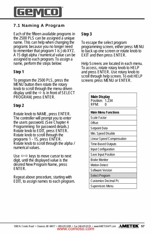
571080 N. Crooks Road • Clawson, MI 48017 • 800.635.0289 • Fax 248.435.8120 • www.AMETEKAPT.com
Main DisplayPosition: 1.234RPM: 0
Main Menu FunctionsScale FactorOffsetSetpoint DataMin. Speed DisableLinear Speed CompensationTime-Based OutputsInput Confi gurationSave Input PositionBrake MonitorMotion DetectSoftware VersionSelect ProgramCustomize Decimal Pt.Supervisors Menu
7.1 Naming A Program
Each of the fi fteen available programs in the 2500 PLS can be assigned a unique name. This can help when changing the programs because you no longer need to remember that program 1 is Job XYZ. A 15 digit alpha / numerical value can be assigned to each program. To assign a name, perform the steps below:
Step 1
To program the 2500 PLS, press the MENU button then rotate the rotary knob to scroll through the menu driven display until the is in front of SELECT PROGRAM, press ENTER.
Step 2
Rotate knob to NAME, press ENTER. The controller will prompt you to enter the users password. (See Chapter 4 Programming: for password details.)Rotate knob to EDIT, press ENTER.Rotate knob to scroll through the programs 1 - 15, press ENTER.Rotate knob to scroll through the alpha / numerical values.
Use keys to move cursor to next digit, until the displayed value is the desired New Program Name, press ENTER.
Repeat above procedure, starting with EDIT, to assign names to each program.
Step 3
To escape the select program programming screen, either press MENU to back up one screen or rotate knob to EXIT and then press ENTER.
Help Screens are located in each menu. To access, rotate rotary knob to HELP and press ENTER. Use rotary knob to scroll through help screen. To exit HELP screens press MENU or ENTER.
www.comoso.com

58 1080 N. Crooks Road • Clawson, MI 48017 • 800.635.0289 • Fax 248.435.8120 • www.AMETEKAPT.com
Main DisplayPosition: 1.234RPM: 0
Main Menu FunctionsScale FactorOffsetSetpoint DataMin. Speed DisableLinear Speed CompensationTime-Based OutputsInput Confi gurationSave Input PositionBrake MonitorMotion DetectSoftware VersionSelect ProgramCustomize Decimal Pt.Supervisors Menu
7.2 Editing A Program
Each of the fi fteen available programs in the 2500 PLS can be recalled and edited at anytime. To edit a program, perform the following steps:
Step 1
To program the 2500 PLS, press the MENU button then rotate the rotary knob to scroll through the menu driven display until the is in front of SELECT PROGRAM, press ENTER.
Step 2
Rotate knob to EDIT, press ENTER.
The controller will prompt you to enter the users password. (See Chapter 4 Programming: for password details.)Rotate knob to scroll through the programs 1 - 15. (The second line of the display will show you the name of the program) press ENTER.
Rotate knob to scroll through available selections, until the value displayed is the desired program, press ENTER.The display will now show you the current program, rotate knob to EXIT, press ENTER.
Step 3
To escape Select Program programming screen, either press MENU to back up one screen or rotate knob to EXIT and then press ENTER.
Help Screens are located in each menu. To access, rotate rotary knob to HELP and press ENTER. Use rotary knob to scroll through help screen. To exit HELP screens press MENU or ENTER.
www.comoso.com

591080 N. Crooks Road • Clawson, MI 48017 • 800.635.0289 • Fax 248.435.8120 • www.AMETEKAPT.com
Main DisplayPosition: 1.234RPM: 0
Main Menu FunctionsScale FactorOffsetSetpoint DataMin. Speed DisableLinear Speed CompensationTime-Based OutputsInput Confi gurationSave Input PositionBrake MonitorMotion DetectSoftware VersionSelect ProgramCustomize Decimal Pt.Supervisors Menu
7.3 Copying A Program
You can copy data from one program to another. This can save time from having to reprogram similar data, such as limit switch settings, that were already created in a previous program. To copy a program’s data to another program, perform the following steps:
Step 1
To program the 2500 PLS, press the MENU button then rotate the rotary knob to scroll through the menu driven display until the
is in front of SELECT PROGRAM, press ENTER.
Step 2
Rotate knob to COPY, press ENTER. The controller will prompt you to enter the users password. (See Chapter 4 Programming: for password details.)The display will show, COPY DATA FROM PROGRAM : X
Rotate knob to scroll through the programs 1 - 15. (The second line of the display will show you the name of the program) press ENTER.
The display will show, COPY DATA TO PROGRAM : X
Rotate knob to scroll through the programs 1 - 15. (The second line of the display will show you the name of the program) press ENTER.
The display will now show you the current program, rotate knob to EXIT, press ENTER.
Step 3
To escape Select Program programming screen, either press MENU to back up one screen or rotate knob to EXIT and then press ENTER.
NOTE: When copying programs, the user assigned program name is also transferred. See: Naming a program to change program name.
Help Screens are located in each menu. To access, rotate rotary knob to HELP and press ENTER. Use rotary knob to scroll through help screen. To exit HELP screens, press MENU or ENTER.
www.comoso.com

60 1080 N. Crooks Road • Clawson, MI 48017 • 800.635.0289 • Fax 248.435.8120 • www.AMETEKAPT.com
Main DisplayPosition: 1.234RPM: 0
Main Menu FunctionsScale FactorOffsetSetpoint DataMin. Speed DisableLinear Speed CompensationTime-Based OutputsInput Confi gurationSave Input PositionBrake MonitorMotion DetectSoftware VersionSelect ProgramCustomize Decimal Pt.Supervisors Menu
7.4 Accessing A Program
A specifi c program can be accessed from the controller’s memory at anytime. To access a program, perform the following steps:
Step 1
To program the 2500 PLS, press the MENU button then rotate the rotary knob to scroll through the menu driven display until the is in front of SELECT PROGRAM, press ENTER.
Step 2
Rotate knob to EDIT, press ENTER. The controller will prompt you to enter the users password. (See Chapter 4 Programming: for password details.)
Rotate knob to scroll through the programs 1 - 15. (The second line of the display will show you the name of the program) press ENTER.
Rotate knob to scroll through available selections, until the value displayed is the desired program, press ENTER.The display will now show you the current program, rotate knob to EXIT, press ENTER.
Step 3
To escape Select Program programming screen, either press MENU to back up one screen or rotate knob to EXIT and then press ENTER.
Help Screens are located in each menu. To access, rotate rotary knob to HELP and press ENTER. Use rotary knob to scroll through help screen. To exit HELP screens press MENU or ENTER.
www.comoso.com

611080 N. Crooks Road • Clawson, MI 48017 • 800.635.0289 • Fax 248.435.8120 • www.AMETEKAPT.com
Main DisplayPosition: 1.234RPM: 0
Supervisor Menu FunctionsCustomize DisplayDefi ne Supv. PasswordDefi ne User PasswordDefi ne Title ScreenSet Fault Clear OptionEnable Brake InputLockout FunctionsInitialize SystemInitialize ProgramLabel OutputsLabel InputsExpansion Boards
7.5 Initialize Program
The Initialize Program function will erase all programmed values for a selected program. You can clear a program and its data at any time. After clearing a program, the program number name will default back to factory default. To initialize a program, perform the following steps:
Step 1
To program the 2500 PLS, press the MENU button then rotate the rotary knob to scroll through the menu driven display until the is in front of Supervisor Menu, press ENTER.
The controller will prompt you to enter the supervisor password. (See Chapter 4 Programming: for password details.)
Rotate knob until the is in front of INITIALIZE SYSTEM, press ENTER. The display will show SELECT PROGRAM. Rotate knob to the desired program that you wish to erase, press ENTER. The display will show REINITIALIZE ALL DATA IN PROGRAM X ?. Rotate knob to either YES or NO, press ENTER.
Step 2
If you answered YES to reinitialize the unit, it will ask you to re-verify your password, once you enter your supervisor password the display will show, PROGRAM INITIALIZATION IN PROCESS… PLEASE WAIT.This procedure will take a few minutes to complete.
Step 3
To escape Initialize Program programming screen, either press ENTER to accept or MENU to back up one screen.
www.comoso.com

62 1080 N. Crooks Road • Clawson, MI 48017 • 800.635.0289 • Fax 248.435.8120 • www.AMETEKAPT.com
Glue Gun
Carton
Resolver
Timing Sprocket& Chain
2500 ProgrammableLimit Switch
2500 SERIES PLS
SCROLL
MENUENTER
AUTOMATION & PROCESS TECHNOLOGIES
R
Figure 8-1
Linear Speed Compensation refers to the ability for the 2500 controller to allow channels to be individually selected and programmed to advance or retard setpoints depending on the speed of the machine. Linear speed compensation is used to compensate for mechanical lag in glue guns and actuators that must be precisely synchronized with the position of the product moving through a process. Without speed compensation, a glue bead may tend to drift out of position as machine speed increases. By properly programming speed compensation for the output channel controlling the glue gun, the glue bead position can be maintained precisely over the complete range of machine speed.
The values assigned in the Linear Speed Channel establish the rate (counts per RPM) for the specifi ed output. A different rate of change can be programmed for the leading edge (ON offset) and the trailing edge (OFF offset) of the ON/OFF dwells on the selected output channel.
For example, Fig. 8-1 shows a simple gluing application. A conveyor moves cartons under a glue gun which dispenses glue onto the fl aps. The resolver is connected in a 1:1 relationship so that one revolution is equal to one carton.
Let’s say we programmed output channel one to come on at 90 degrees and go off at 270 degrees, with an ON offset value of 20 degrees for every 100 RPM and an OFF offset of 10 degrees for every 100 RPM. This will advance the leading edge of all setpoints on output channel 1 by 20 counts and their trailing edge by 10 counts for every 100 RPM increase in resolver velocity. This rate of advance is applied linearly as speed increases from zero and will continue as speeds increase beyond 100 RPM. In other words, if the resolver increased to 50 RPM, the setpoint’s leading edge would advance by 10 counts and its trailing edge would advance by 5 counts. This is illustrated in Fig. 8-2.
Chapter 8: Linear Speed Compensation
www.comoso.com

631080 N. Crooks Road • Clawson, MI 48017 • 800.635.0289 • Fax 248.435.8120 • www.AMETEKAPT.com
Figure 8-2:
0
270
180
90
Zero Speed
270
100 RPM
@ 70At 100 RPM LS1 would energize
and de-energize @ 260
180
90
0
270
400 RPM
At 400 RPM LS1 would energize
@ 10 and de-energize @ 230
180
90
0
260
70
230
10
Figure 8-3:
At very slow, or essentially zero speed, the glue gun would be energized at resolver position of 90 degrees and de-energized at 270 degrees. As the line speed increases, the glue guns need to
be energized before 90 degrees to allow the glue to hit the carton in the correct spot. The faster the line speed, the sooner in the resolver’s cycle the glue gun must be triggered.
Countsof Advance
Resolver’sRPM
0
5
10
15
20
0 50 100 150 200
(on se
tpoin
ts)
(off setpoints)
On setpoints advance by 20 counts and off setpoints advance by 10 counts as the resolver increases to 100 RPM. The rate of advance is applied linearly as the resolver’s RPM moves above or below 100 RPM.
Linear Speed Compensation at Various Speeds
The examples below show the Linear Speed Offset using the previously stated parameters.
www.comoso.com

64 1080 N. Crooks Road • Clawson, MI 48017 • 800.635.0289 • Fax 248.435.8120 • www.AMETEKAPT.com
Main DisplayPosition: 1.234RPM: 0
Main Menu FunctionsScale FactorOffsetSetpoint DataMin. Speed DisableLinear Speed CompensationTime-Based OutputsInput Confi gurationSave Input PositionBrake MonitorMotion DetectSoftware VersionSelect ProgramCustomize Decimal Pt.Supervisors Menu
This feature allows any of the 64 outputs to automatically advance or retard as machine velocity varies. The number of circuits affected by linear speed compensation, the amount of on and off offset, and the RPM range over which the offset develops, are all programmable. The amount to offset per RPM change can be different for each output. This feature can be used to compensate for the mechanical lag in machine controls. To program a circuit for linear speed compensation, perform the following steps:
Step 1
To program the 2500 PLS, press the MENU button then rotate the rotary knob to scroll through the menu driven display until the is in front of function desired, press ENTER.
Step 2
Rotate knob to select desired Linear Speed Channel, press ENTER. Rotate knob to EDIT, press ENTER. The controller will prompt you to enter the users password. See Chapter 4 Programming: for password details.The controller will prompt you to enter New Linear Speed RPM Value.
Rotate knob to increase / decrease numerical values. Use keys to move cursor to next digit, until the displayed value is the desired New Linear Speed RPM Value, press ENTER. The controller will prompt you to enter New Linear Speed On Count Value.
Rotate knob to increase / decrease numerical values. Use keys to move cursor to next digit, until the displayed value is the desired New Linear Speed On
Count Value, press ENTER. The controller will prompt you to enter New Linear Speed Off Count Value. Rotate knob to increase / decrease numerical values. Use keys to move cursor to next digit, until the displayed value is the desired New Linear Speed Off Count Value, press ENTER.
Step 3
To escape the Speed Compensation programming screen, either press MENU to back up one screen or rotate knob to EXIT and then press ENTER.
8.1 Linear Speed Compensation
RPM = The RPM value at which the ON or OFF will move the specifi ed amount of counts. OFF = The amount of counts
that the OFF point will move at the selected RPM.
ON = The amount of counts that the ON point will move at the selected RPM.Display
RPM 500 ON:100 EDIT OFF:50 EXIT
www.comoso.com

651080 N. Crooks Road • Clawson, MI 48017 • 800.635.0289 • Fax 248.435.8120 • www.AMETEKAPT.com
Main DisplayPosition: 1.234RPM: 0
Main Menu FunctionsScale FactorOffsetSetpoint DataMin. Speed DisableLinear Speed CompensationTime-Based OutputsInput Confi gurationSave Input PositionBrake MonitorMotion DetectSoftware VersionSelect ProgramCustomize Decimal Pt.Supervisors Menu
8.2 Minimum Speed Disable
This feature allows limit switch output channels that have been programmed as linear speed channels to be automatically turned off if machine speed drops below a programmed RPM value. It can also be used to prevent output channels from turning on until a desired operating speed is reached. Typical uses include turning off glue guns or retracting actuators to a safe position under emergency stop conditions. To program a linear speed compensation channel for minimum speed offset, perform the following steps:
Step 1
To program the 2500 PLS, press the MENU button then rotate the rotary knob to scroll through the menu driven display until the is in front of function desired, press ENTER.
Step 2
Rotate knob to EDIT, press ENTER.The controller will prompt you to enter the users password. (See Chapter 4 Programming: for password details.) Rotate knob to increase / decrease numerical values.
Use keys to move cursor to next digit, until the displayed value is the desired New Minimum Speed Disable Value, press ENTER.
Step 3
To escape Min. Speed Disable programming screen, either press MENU to back up one screen or rotate knob to EXIT and then press ENTER.
NOTE: Only outputs that are programmed with linear speed compensation can have a minimum speed disable setting.
www.comoso.com

66 1080 N. Crooks Road • Clawson, MI 48017 • 800.635.0289 • Fax 248.435.8120 • www.AMETEKAPT.com
Main DisplayPosition: 1.234RPM: 0
Main Menu FunctionsScale FactorOffsetSetpoint DataMin. Speed DisableLinear Speed CompensationTime-Based OutputsInput Confi gurationSave Input PositionBrake MonitorMotion DetectSoftware VersionSelect ProgramCustomize Decimal Pt.Supervisors Menu
In instances where it is desirable to have outputs actuate based on resolver position and turn off based on time, we offer time-based outputs. Examples of where time-based limits are applicable include lubricators, air blow-off limits and pneumatic cylinders which require a fi xed amount of time to perform a task. Valid selections are 0.01 to 9.99 seconds. Any or all of the 2500 PLS outputs can be programmed for Time-Based outputs. However, limit switches cannot be programmed for both Linear Speed Compensation and Time-Based outputs at the same time. To program an output for time based operation, perform the following steps:
Step 1
To program the 2500 PLS, press the MENU button then rotate the rotary knob to scroll through the menu driven display until the is in front of function desired, press ENTER.
Step 2
Rotate knob to select desired Time Based Channel, press ENTER.Rotate knob to EDIT, press ENTER.
The controller will prompt you to enter the users password. (See Chapter 4 Programming: for password details.) The controller will prompt you to enter New On Position Value.
Rotate knob to increase / decrease numerical values. Use keys to move cursor to next digit, until the displayed value is the desired New On Position Value, press ENTER.
Chapter 9: Time Based OutputsThe controller will prompt you to enter New Time Duration Value. Rotate knob to increase / decrease numerical values. Use keys to move cursor to next digit, until the displayed value is the desired New Time Duration Value, press ENTER.
Step 3
To escape Time Based programming screen, either press MENU to back up one screen or rotate knob to EXIT and then press ENTER.
Help Screens are located in each menu. To access, rotate rotary knob to HELP and press ENTER. Use rotary knob to scroll through help screen. To exit HELP screens press MENU or ENTER.
www.comoso.com

671080 N. Crooks Road • Clawson, MI 48017 • 800.635.0289 • Fax 248.435.8120 • www.AMETEKAPT.com
Chapter 10: Inputs
This section describes the eight inputs that are on every main controller and expansion module, each input is internally tied to its corresponding output. Each input can be confi gured as a reset-to-preset, output enabler input, or a die protection input. Inputs 1 - 8 require a PNP sourcing device type input signal. A status LED for each input is conveniently located on the back of the controller.
The eight inputs are arranged on a 16 place terminal strip, as shown in fi gure 3-5. Each input is optically isolated and can be powered from an external DC power source. Many types of hardware can drive these inputs, including mechanical switches, relay contacts, DC 3 wire sensors, 3 wire proximity sensors, solid-state DC output modules, and PLC DC outputs. See fi gure 3-12 for wiring diagram.
Input Functions• No Input• Reset to Preset Continuous• Reset to Preset Single• Die Protection Momentary• Die Protection Maintain• Die Protection Partial• Output Enable One Shot• Output Enable Level• Save Input Position
No InputNo input type has been confi gured for this input. The controller will ignore any activity on this input when it is in the No Input mode.
Reset to Preset The reset to preset input allows selected output channels to be reset to a programmed position value upon seeing an input from a remote sensor. This type of input is typically used in applications where parts are randomly spaced as they enter the workstation.
A photoelectric or proximity switch is used to sense the leading edge of the product. Upon seeing the leading edge of the part entering the workstation, output channels can be reset to a preset position value. The output channels will then begin to operate based on their on/off setpoints relative to a preset value which has been synchronized with the leading edge of the product.
Because the reset to preset input resets the output channels positions when it senses a part entering the workstation, it doesn’t matter at what position on the resolver a part enters the workstation. In fi gure 10-1, output channel 1 has been programmed to have a reset to preset value of zero. During machine operation, input channel 1 becomes energized at machine position 180°. Because output channel 1 is linked to input channel 1, it resets to 0°. In this way, the outputs energize at the proper position, according to their on/off setpoints relative to the position at which the input was energized.
NOTE: Each input is internally tied to its corresponding output and cannot be changed. In cases where one input is used to control more than one output, simply daisy chain the inputs together.
www.comoso.com

68 1080 N. Crooks Road • Clawson, MI 48017 • 800.635.0289 • Fax 248.435.8120 • www.AMETEKAPT.com
Figure 10 - 1:
There are two modes of operation for the reset inputs. They are as follows:
Continuous Mode The selected output channel resets to the preset position value upon seeing the input. The setpoint will operate over its programmed value continuously. As the resolver continues to rotate through zero, the output channel will continue to track the reset resolver position and the setpoints will operate at the programmed values. For instructions on how to program the inputs to operate in the continuous mode, see Reset to Preset Continuous.
Reset to Preset SingleThe reset to preset single shot input can be programmed to reset its associated output channel to zero or some other value upon activation of the input. The setpoints will operate over their programmed values through one revolution of the resolver. After one complete revolution, the output channel will remain de-energized until the next reset input is sensed. See fi gure 10-2.
For instruction on how to program the inputs to operate in the single shot mode, see Reset to Preset Single.
sensor
glue gun
F 4
A 2
50V
F 4
A 2
50V
F 4
A 2
50V
F 4
A 2
50V
F 4
A 2
50V
F 4
A 2
50V
F 4
A 2
50V
F 4
A 2
50V
OUT4
w
BK IN OUT1
VTR
5C
ED
S
w
OUT2
TR
5
ED
CS
V w
OUT3
SE
DC
TR
5
V w TR
5
SE
D VC
OUT6
VS
OUT5
SE
D VC
TR
5
w TR
5C
ED
OUT7
TR
5
w w
SE
D VC
OUT8
TR
5
SE
D VC
w
INPUT STATUS
IN4
L1
AC POWER
50/60 Hz
INTERNALLY FUSED
100-240 VAC
GN
D
IN1 IN2 IN3
L2
IN6IN5 IN7 IN8
Outputs 1-8
Inputs 1-8
Although the part was positioned at 180 according to the resolver, the output channels’ position linked to the input are reset to 0.
Glue guns are reset to 0 and will apply glue properly onto the part, regardless of when the part entered the workstation.
www.comoso.com

691080 N. Crooks Road • Clawson, MI 48017 • 800.635.0289 • Fax 248.435.8120 • www.AMETEKAPT.com
Figure 10 - 2: Example Application
Input sensor #1
Output #1 glue head
Output #2 glue head
Input sensor #2
Output #3 glue head
Input sensor #3
Conveyor
Direction
One ResolverProvides PositionInformation forAll Glue Heads
Glue Beads
Figure 10-2 shows three different glue heads in different locations on the conveyor being controlled by a single controller and resolver. Any or all of the available 64 outputs can be confi gured as a reset to preset without compromising the update time of the controller. The spacing between the parts being glued is random. Each output on the controller is capable of keeping track of its own position.
The PNP type sensors are connected to the input terminals. When a sensor detects a product, it resets its corresponding output’s position to the preset value and enables that output to turn on at the programmed positions through one revolution of the resolver. After one complete revolution, the output channel will remain de-energized until the next reset input is detected.
Die ProtectionDie Protection is typically used in the stamping industry to protect the dies from damage as a part progresses through the die. For a more detailed explanation and programming see Chapter 11.
Output Enabler Output enabler inputs are used to enable or disable output channels based upon sensing a critical event prior to or during each rotation of the resolver. Typically used to verify that a product is present at a glue station prior to allowing the glue guns to operate. There are two modes of operation for the output enabler inputs. They are:
Output Enabler One ShotIn one-shot mode, you program a window in which the input must change state in order to allow the linked output channel to operate
over the current rotation of the resolver. If the input does not change states within the programmed window, the linked output will not operate. In fi gure 10:3, the output enable input 2 is linked to output channel 2. When the input senses the part, the glue guns controlled by the output channel are enabled, and will apply glue onto the part according to the on/off setpoints. However, if a part is not sensed within the programmed window, the linked output channel will be disabled through that rotation of the resolver. For instructions on how to program the inputs to operate in the output enable one-shot mode, see Output Enable One Shot.
NOTE: In order for an output enable input (one-shot mode) to enable the output channel, the input must transition sometime between the resolver’s zero position and the fi rst on setpoint position of the output channel. The output enabler input can remain energized for any duration - as long as it de-energizes before it transitions again within its window.
www.comoso.com

70 1080 N. Crooks Road • Clawson, MI 48017 • 800.635.0289 • Fax 248.435.8120 • www.AMETEKAPT.com
Chart represents the input channel #2’s window of detection (35 to 45) and the input’s actual transition. Notice that the input detection window closes before the output channels’ first on/off dwell.
Sensor must detect part between 35 and 45 in order to enable glue gun.
sensor
glue gun
F 4
A 2
50V
F 4
A 2
50V
F 4
A 2
50V
F 4
A 2
50V
F 4
A 2
50V
F 4
A 2
50V
F 4
A 2
50V
F 4
A 2
50V
OUT4
w
BK IN OUT1
VTR
5C
ED
S
w
OUT2
TR
5
ED
CS
V w
OUT3
SE
DC
TR
5
V w TR
5
SE
D VC
OUT6
VS
OUT5
SE
D VC
TR
5
w TR
5C
ED
OUT7
TR
5
w w
SE
D VC
OUT8
TR
5
SE
D VC
w
INPUT STATUS
IN4
L1
AC POWER
50/60 Hz
INTERNALLY FUSED
100-240 VAC
GN
D
IN1 IN2 IN3
L2
IN6IN5 IN7 IN8
Input 2
Input 2 35 45
Output Channel #2
Input Channel #2
Figure 10 - 3:
Output Enable LevelThe output enable level mode will operate like a simple AND input. The output pattern will only operate as long as the output enabler input is energized or de-energized. Therefore, the product presence sensor must provide an input during the full duration of the limit switch output pattern. If the input goes to the wrong state, the output channel will de-energize. For instruction on how to program the inputs to operate in the output enable level mode, see Output Enable Level Mode.
Save Input PositionThe save input position feature can be used at any time to save the resolver position to any or all of the output channels that have been confi gured with a Reset-to-Preset input. When setting up an input for reset-to-preset, the controller will ask a series of questions. One of the questions is when to save the reset position to memory. The selections are EVERYTIME, NEVER, or THRU INPUT SAVE. The electronic part which saves the resolver position has an infi nite life, which means that it is guaranteed to save the position 100,000 times before the part is worn out. This is why during the setup of the reset inputs you must select how and when the position is stored.
www.comoso.com

711080 N. Crooks Road • Clawson, MI 48017 • 800.635.0289 • Fax 248.435.8120 • www.AMETEKAPT.com
Main DisplayPosition: 1.234RPM: 0
Main Menu FunctionsScale FactorOffsetSetpoint DataMin. Speed DisableLinear Speed CompensationTime-Based OutputsInput Confi gurationSave Input PositionBrake MonitorMotion DetectSoftware VersionSelect ProgramCustomize Decimal Pt.Supervisors Menu
• Every time: Every time the input sees a transition it saves the resolver position to memory. With this option, if power is lost, the position associated with that output will be retained. This option should not be used in applications where each time a product is produced, the input is reset, as shown in fi gures 10-1 or 10-2.
• Never: Never, is typically used in a high speed packaging application where it is necessary to reset an output position to zero each time a
product passes under the input sensor. Since every time a product appears under the sensor the output resets to zero, it is not necessary to store this value. With this option, if power is lost, the position associated with that output will not be retained.
• Save Input Position: The save input position feature can be used at any time to save the resolver position to any or all of the output channels that have been confi gured for a Reset-to-Preset input.
Any one or all of the 64 available limit switch outputs can be confi gured with an input. These inputs can enhance the way the output will function. The introduction of inputs in Chapter 10 will give you a clear explanation on how and where such inputs can be used. Valid selections for inputs are: No Input Type, Reset to Preset Continuous, Reset to Preset Single, Die Protect Momentary, Die Protect Maintain, Die Protect Partial, Output Enable One Shot, and Output Enable Level. The programming sequence for each option is different. Please refer to subsequent pages for programming details.
Step 1
To program the 2500 PLS, press the MENU button then rotate the rotary knob to scroll through the menu driven display until the is in front of function desired, press ENTER.
10.1 Input Confi guration
www.comoso.com

72 1080 N. Crooks Road • Clawson, MI 48017 • 800.635.0289 • Fax 248.435.8120 • www.AMETEKAPT.com
Represents value that position will reset to when input #7 is made.
Represents input #7 is set for Reset to Preset Continuous Mode.
DisplayIN: 7 RESET-CONT. EDIT PRESET: 0.0000 EXIT
Step 2
Rotate knob to select desired Input Confi guration Channel, press ENTER.
Rotate knob to EDIT, press ENTER.
The controller will prompt you to enter the users password. (See Chapter 4 Programming: for password details.)
The controller will prompt you to enter New Input Type.
Rotate knob to scroll through selections.
Valid selections are:
NO INPUT TYPERESET TO PRESET CONTINUOUSRESET TO PRESET SINGLEDIE PROTECT MOMENTARYDIE PROTECT MAINTAINDIE PROTECT PARTIALOUTPUT ENABLE ONE SHOTOUTPUT ENABLE LEVEL
Use the rotary knob until the displayed value is the desired New Input Type, press ENTER.
The remaining programming steps are different for each input type. Refer to programming section for option selected to complete the programming process.
www.comoso.com

731080 N. Crooks Road • Clawson, MI 48017 • 800.635.0289 • Fax 248.435.8120 • www.AMETEKAPT.com
Main DisplayPosition: 1.234RPM: 0
Main Menu FunctionsScale FactorOffsetSetpoint DataMin. Speed DisableLinear Speed CompensationTime-Based OutputsInput Confi gurationSave Input PositionBrake MonitorMotion DetectSoftware VersionSelect ProgramCustomize Decimal Pt.Supervisors Menu
Step 1
To program the 2500 PLS, press the MENU button then rotate the rotary knob to scroll through the menu driven display until the is in front of function desired, press ENTER.
Step 2
Rotate knob to select desired Input Confi guration Channel (the second line of the display will show you how the input is presently confi gured), press ENTER.
Rotate knob to EDIT, press ENTER.
The controller will prompt you to enter the users password. (See Chapter 4 Programming: for password details.)The controller will prompt you to enter New Input Type.
Rotate knob to scroll through selections until NO INPUT TYPE is displayed, press ENTER.
NOTE: When set to No Input Type the controller will ignore any activity on that selected input.
Step 3
To escape Input Confi guration programming screen, either press MENU to back up one screen or rotate knob to EXIT and then press ENTER.
Help Screens are located in each menu. To access, rotate rotary knob to HELP and press ENTER. Use rotary knob to scroll through help screen. To exit HELP screens press MENU or ENTER.
10.2 Input Confi guration for No Input
www.comoso.com
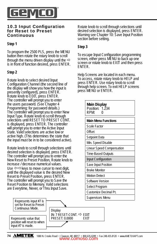
74 1080 N. Crooks Road • Clawson, MI 48017 • 800.635.0289 • Fax 248.435.8120 • www.AMETEKAPT.com
Main DisplayPosition: 1.234RPM: 0
Main Menu FunctionsScale FactorOffsetSetpoint DataMin. Speed DisableLinear Speed CompensationTime-Based OutputsInput Confi gurationSave Input PositionBrake MonitorMotion DetectSoftware VersionSelect ProgramCustomize Decimal Pt.Supervisors Menu
Represents value that position will reset to when input #7 is made.
Represents input #7 is set for Reset to Preset Continuous Mode. Display
IN: 7 RESET-CONT. EDIT PRESET: 0.0000 EXIT
10.3 Input Confi guration for Reset to Preset Continuous
Step 1
To program the 2500 PLS, press the MENU button then rotate the rotary knob to scroll through the menu driven display until the is in front of function desired, press ENTER.
Step 2
Rotate knob to select desired Input Confi guration Channel (the second line of the display will show you how the input is presently confi gured), press ENTER. Rotate knob to EDIT, press ENTER. The controller will prompt you to enter the users password. (See Chapter 4 Programming: for password details.)The controller will prompt you to enter New Input Type. Rotate knob to scroll through selections until RESET TO PRESET CONT. is displayed, press ENTER. The controller will prompt you to enter the Active Input State. Valid selections are active low or active high. (This determines the state that the input must be in to be considered active).
Rotate knob to scroll through selections until desired selection is displayed, press ENTER. The controller will prompt you to enter the New Reset to Preset Position, Rotate knob to increase / decrease numerical values.Use keys to move cursor to next digit, until the displayed value is the desired New Reset to Preset Position, press ENTER. The controller will prompt you to Save the Reset Position to Memory. Valid selections are Everytime, Never, or Thru Input Save.
Rotate knob to scroll through selections until desired selection is displayed, press ENTER. Warning see Chapter 10: Save Input Position section before setting.
Step 3
To escape Input Confi guration programming screen, either press MENU to back up one screen or rotate knob to EXIT and then press ENTER.
Help Screens are located in each menu. To access, rotate rotary knob to HELP and press ENTER. Use rotary knob to scroll through help screen. To exit HELP screens press MENU or ENTER.
www.comoso.com

751080 N. Crooks Road • Clawson, MI 48017 • 800.635.0289 • Fax 248.435.8120 • www.AMETEKAPT.com
Main DisplayPosition: 1.234RPM: 0
Main Menu FunctionsScale FactorOffsetSetpoint DataMin. Speed DisableLinear Speed CompensationTime-Based OutputsInput Confi gurationSave Input PositionBrake MonitorMotion DetectSoftware VersionSelect ProgramCustomize Decimal Pt.Supervisors Menu
Represents value that position will reset to when input #7 is made.
Represents input #7 is set for Reset to Preset Continuous Mode. Display
IN: 7 RESET-CONT. EDIT PRESET: 0.0000 EXIT
10.4 Input Confi guration for Reset to Preset Single
Step 1
To program the 2500 PLS, press the MENU button then rotate the rotary knob to scroll through the menu driven display until the is in front of function desired, press ENTER.
Step 2
Rotate knob to select desired Input Confi guration Channel (the second line of the display will show you how the input is presently confi gured), press ENTER. Rotate knob to EDIT, press ENTER. The controller will prompt you to enter the users password. (See Chapter 4 Programming: for password details.)The controller will prompt you to enter New Input Type. Rotate knob to scroll through selections until RESET TO PRESET SINGLE is displayed, press ENTER. The controller will prompt you to enter the Active Input State.
Valid selections are active low or active high. (This determines the state that the input must be in to be considered active).Rotate knob to scroll through selections until desired selection is displayed, press ENTER. The controller will prompt you to enter the New Reset to Preset Position, Rotate knob to increase / decrease numerical values.Use keys to move cursor to next digit, until the displayed value is the desired New Reset to Preset Position, press ENTER. The controller will prompt you to Save the Reset Position to Memory. Valid selections are Everytime, Never, or Thru Input Save.
Rotate knob to scroll through selections until desired selection is displayed, press ENTER. Warning see Chapter 10: Save Input Position section before setting.
Step 3
To escape Input Confi guration programming screen, either press MENU to back up one screen or rotate knob to EXIT and then press ENTER.
Help Screens are located in each menu. To access, rotate rotary knob to HELP and press ENTER. Use rotary knob to scroll through help screen. To exit HELP screens press MENU or ENTER.
www.comoso.com

76 1080 N. Crooks Road • Clawson, MI 48017 • 800.635.0289 • Fax 248.435.8120 • www.AMETEKAPT.com
Main DisplayPosition: 1.234RPM: 0
Main Menu FunctionsScale FactorOffsetSetpoint DataMin. Speed DisableLinear Speed CompensationTime-Based OutputsInput Confi gurationSave Input PositionBrake MonitorMotion DetectSoftware VersionSelect ProgramCustomize Decimal Pt.Supervisors Menu
Represents value that position will reset to when input #7 is made.
Represents input #7 is set for Reset to Preset Single Mode. Display
IN: 7 RESET-SINGLE EDIT PRESET: 0.0000 EXIT
10.5 Input Confi guration for Output Enable One Shot
Step 1
To program the 2500 PLS, press the MENU button then rotate the rotary knob to scroll through the menu driven display until the is in front of function desired, press ENTER.
Step 2
Rotate knob to select desired Input Confi guration Channel (the second line of the display will show you how the input is presently confi gured), press ENTER. Rotate knob to EDIT, press ENTER. The controller will prompt you to enter the users password. (See Chapter 4 Programming: for password details.)The controller will prompt you to enter New Input Type.
Rotate knob to scroll through selections until OUTPUT ENABLE ONE SHOT is displayed, press ENTER. The controller will prompt you to enter the Active Input State. Valid selections are active low or active high. (This determines the state that the input must be in to be considered active). Rotate knob to scroll through selections until desired selection is displayed, press ENTER. The controller will prompt you to enter the New Window On Position. Rotate knob to increase / decrease numerical values. Use keys to move cursor to next digit, until the displayed value is the desired New Window On Position, press ENTER. The controller will prompt you to enter the New Window Off Position. Rotate knob
to increase / decrease numerical values. Use keys to move cursor to next digit, until the displayed value is the desired New Window Off Position, press ENTER.
Step 3
To escape Input Confi guration programming screen, either press MENU to back up one screen or rotate knob to EXIT and then press ENTER.
Help Screens are located in each menu. To access, rotate rotary knob to HELP and press ENTER. Use rotary knob to scroll through help screen. To exit HELP screens press MENU or ENTER.
www.comoso.com

771080 N. Crooks Road • Clawson, MI 48017 • 800.635.0289 • Fax 248.435.8120 • www.AMETEKAPT.com
Main DisplayPosition: 1.234RPM: 0
Main Menu FunctionsScale FactorOffsetSetpoint DataMin. Speed DisableLinear Speed CompensationTime-Based OutputsInput Confi gurationSave Input PositionBrake MonitorMotion DetectSoftware VersionSelect ProgramCustomize Decimal Pt.Supervisors Menu
Represents the state the input must be in to activate the output.
Represents input #7 is set for Output Enabler Level Mode. Display
IN: 7 OE-LEVEL EDIT ACTIVE STATE: LOW EXIT
10.6 Input Confi guration for Output Enable Level
Step 1
To program the 2500 PLS, press the MENU button then rotate the rotary knob to scroll through the menu driven display until the is in front of function desired, press ENTER.
Step 2
Rotate knob to select desired Input Confi guration Channel (the second line of the display will show you how the input is presently confi gured), press ENTER.
Rotate knob to EDIT, press ENTER. The controller will prompt you to enter the users password. (See Chapter 4 Programming: for password details.)The controller will prompt you to enter New Input Type.
Rotate knob to scroll through selections until OUTPUT ENABLE LEVEL is displayed, press ENTER.
The controller will prompt you to enter the Active Input State. Valid selections are active low or active high. (This determines the state that the input must be in to be considered active).
Rotate knob to scroll through selections until desired selection is displayed, press ENTER.
Step 3
To escape Input Confi guration programming screen, either press MENU to back up one screen or rotate knob to EXIT and then press ENTER.
www.comoso.com

78 1080 N. Crooks Road • Clawson, MI 48017 • 800.635.0289 • Fax 248.435.8120 • www.AMETEKAPT.com
The Enable Brake Input function is used to enable or disable the Brake input relay. Valid selections are DISABLED, ENABLED AS BRAKE MONITOR, or ENABLED AS GLOBAL R-TO-P. This input relay is optional and if ordered, it will be installed in the lower left hand relay slot located next to output number 1.
Using the rotary knob you can scroll through the displayed settings. For Brake monitoring details see Section 5.10 Section 12. For Global Reset to Preset see addendum. For programming see example below.
To program the 2500 PLS, press the MENU button then rotate the rotary knob to scroll through the menu driven display until the is in front of Supervisor Menu, press ENTER. The controller will prompt you to enter the supervisor password. (See Chapter 4 Programming: for password details.)
Rotate knob until the is in front of ENABLE BRAKE INPUT, press ENTER Rotate knob until desired setting is displayed, press ENTER.
To escape Enable Brake Input programming screen, press MENU to back up one screen.
NOTE: This feature is only used to activate the Brake input relay. To program the Brake Monitor or Global Reset to Preset options refer to programming sections.
Chapter 10.7: Enable Brake Input
Main DisplayPosition: 1.234RPM: 0
Supervisor Menu FunctionsCustomize DisplayDefi ne Supv. PasswordDefi ne User PasswordDefi ne Title ScreenSet Fault Clear OptionEnable Brake InputLockout FunctionsInitialize SystemInitialize ProgramLabel OutputsLabel InputsExpansion Boards
www.comoso.com

791080 N. Crooks Road • Clawson, MI 48017 • 800.635.0289 • Fax 248.435.8120 • www.AMETEKAPT.com
To 2500Die Protection Inputs
PNP Type (Sourcing)
+
-
Customer Supplied 10-30VDC
Power Supply+-
Figure 11-1: Open Collector Device, Photo Switches, Proximity Switches, etc.
Die protection inputs are used to protect dies from damage due to mis-sequence or buildup of material. This is accomplished by comparing inputs from sensors mounted on or near the dies to dwells programmed into the controller. If the sensors do not change states within the programmed dwell area, a fault can occur depending on how the inputs are programmed.
The 2500 is capable of 8 programmable die protection inputs and is expandable to 64 by using the expansion modules. They are found on the bottom of the controller. See Figure 3-5 for the location of these inputs.
Programming a die protection input is like programming a limit switch; it needs a dwell on position and a dwell off position. Within this window, a sensing device is used to determine if a process has occurred during a stroke. For example, after the press has formed a part, the part has to be expelled from the die before a new stroke occurs. This is typically accomplished through an air blow off valve, which blows the part out of the die area.
If the part is not ejected (due to material buildup or some other fault in the process), a sensor such as a photo switch or light curtain would not detect the ejection. As a result, a fault would occur. The output associated with the die protection’s input will come on, which could stop the press.
11.1 Applications for Die Protection Inputs
This section describes how the die protection inputs can be programmed for the following three modes:
• Momentary• Partial Revolution Constant Monitor• Maintain
MomentaryA die protection input programmed in momentary mode only needs to sense something once while the resolver is in the input’s programmed dwell window. For example, a N.O. light curtain could be used to detect a part being ejected from a press. When the part is ejected between a programmed dwell window, the light
Chapter 11: Die Protection Inputs
www.comoso.com

80 1080 N. Crooks Road • Clawson, MI 48017 • 800.635.0289 • Fax 248.435.8120 • www.AMETEKAPT.com
0
270
180
90
Dotted area represents the momentary dwell window; the period in which a part must be sensed.
Shaded area represents the period the part passes through the light curtain. Fault does not occur because input isdetected at sometime within the momentary window
Fault does not occur because input is
Shaded area represents the period in
Fault occurs because input is not detected
Dotted area represents the partial
0
270
180
90
180
270
0
90
revolution constant monitor dwell window.
throughout the partial revolution constant monitor dwell window.
which an input is detected.
detected throughout the partial revolution constant monitor dwell window.
Figure 11-2: Light Curtain Detecting and Ejected Part
Figure 11-2 Buckle, Metal Bounces When Hit
curtain’s N.O. circuit would close. If a part is not detected within the programmed dwell window, the limit switch’s output will come on. This could top stop or E-STOP the press, if properly wired (see Figure 11-1). To make this possible, the sensor needs to be connected to one of the die protection inputs. This input would then need to be programmed with a dwell on and dwell off position.
Partial Revolution Constant MonitorAn input programmed in partial revolution constant monitor mode monitors only during a part of the revolution (the dwell window the user programs), the input must be made during the entire programmmed window or a die protection fault will occur, as shown in Figure 11-2.
www.comoso.com

811080 N. Crooks Road • Clawson, MI 48017 • 800.635.0289 • Fax 248.435.8120 • www.AMETEKAPT.com
Figure 11-3 Proximity Switch Monitoring for Short Feeds
0
270
180
90
Fault does not occur because input is detected to the end of the mantain dwell window.
Shaded area represents the period in which an input is detected.
180
270
0
90
Fault occurs because input is not detected to the end end of the maintain dwell window.
Dotted area represents the mantain dwell window.
MaintainAn Input programmed in maintain mode can be used to detect a short feed of material into the press. After material is fed into the press, a device usually is used to clamp onto the material. This prevents the material from moving before the die is engaged. But sometimes the material can be pulled back just before the clamps are engaged. A sensor programmed with the maintain mode is able to sense this type of fault. It will monitor the material until the end of the revolution it was programmed to monitor, as shown in Figure 11-3.
www.comoso.com

82 1080 N. Crooks Road • Clawson, MI 48017 • 800.635.0289 • Fax 248.435.8120 • www.AMETEKAPT.com
Main DisplayPosition: 1.234RPM: 0
Main Menu FunctionsScale FactorOffsetSetpoint DataMin. Speed DisableLinear Speed CompensationTime-Based OutputsInput Confi gurationSave Input PositionBrake MonitorMotion DetectSoftware VersionSelect ProgramCustomize Decimal Pt.Supervisors Menu
DisplayIN: 7 DP-MOMENTARY EDIT WIN: 0.0000 - 1.000 EXITRepresents Die Protect
window ON at 0.0000 and OFF at 1.000.
Represents input #7 is set for Die Protection Momentary.
11.2 Input Confi guration for Die Protect Momentary
Step 1
To program the 2500 PLS, press the MENU button then rotate the rotary knob to scroll through the menu driven display until the
is in front of function desired, press ENTER.
Step 2
Rotate knob to select desired Input Confi guration Channel (the second line of the display will show you how the input is presently confi gured), press ENTER. Rotate knob to EDIT, press ENTER. The controller will prompt you to enter the users password. (See Chapter 4 Programming: for password details.)The controller will prompt you to enter New Input Type. Rotate knob to scroll through selections until DIE PROTECT MOMENTARY is displayed, press ENTER.
The controller will prompt you to enter the Active Input State. Valid selections are normally open or normally closed. (This determines the state that the input must be in to be considered active). Rotate knob to scroll through selections until desired selection is displayed, press ENTER. The controller will prompt you to enter the New Window On Position, Rotate knob to increase / decrease numerical values. Use keys to move cursor to next digit, until the displayed value is the desired New Window On Position, press ENTER. The controller will prompt you to enter the New Window Off Position,
Rotate knob to increase / decrease numerical values. Use keys to move cursor to next digit, until the displayed value is the desired New Window Off Position, press ENTER.
Step 3
To escape Input Confi guration programming screen, either press MENU to back up one screen or rotate knob to EXIT and then press ENTER.
Help Screens are located in each menu. To access, rotate rotary knob to HELP and press ENTER. Use rotary knob to scroll through help screen. To exit HELP screens press MENU or ENTER.
www.comoso.com

831080 N. Crooks Road • Clawson, MI 48017 • 800.635.0289 • Fax 248.435.8120 • www.AMETEKAPT.com
Display IN: 7 DP-MAINTAIN EDIT WIN: 0.0000 - 1.000 EXITRepresents Die Protect
window ON at 0.0000 and OFF at 1.000.
Represents input #7 is set for Die Protect Maintain.
11.3 Input Confi guration for Die Protect Maintain
Step 1
To program the 2500 PLS, press the MENU button then rotate the rotary knob to scroll through the menu driven display until the is in front of function desired, press ENTER.
Step 2
Rotate knob to select desired Input Confi guration Channel (the second line of the display will show you how the input is presently confi gured), press ENTER. Rotate knob to EDIT, press ENTER. The controller will prompt you to enter the users password. (See Chapter 4 Programming: for password details.)
The controller will prompt you to enter New Input Type. Rotate knob to scroll through selections until DIE PROTECT MAINTAIN is displayed, press ENTER. The controller will prompt you to enter the Active Input State. Valid selections are normally open or normally closed. (This determines the state that the input must be in to be considered active). Rotate knob to scroll through selections until desired selection is displayed, press ENTER. The controller will prompt you to enter the New Window On Position, Rotate knob to increase / decrease numerical values. Use keys to move cursor to next digit, until the displayed value is the desired New Window On Position, press ENTER. The controller will prompt you to enter the New Window Off Position, Rotate knob to increase / decrease
numerical values. Use keys to move cursor to next digit, until the displayed value is the desired New Window Off Position, press ENTER.
Step 3
To escape Input Confi guration programming screen, either press MENU to back up one screen or rotate knob to EXIT and then press ENTER.
Help Screens are located in each menu. To access, rotate rotary knob to HELP and press ENTER. Use rotary knob to scroll through help screen. To exit HELP screens press MENU or ENTER.
Main DisplayPosition: 1.234RPM: 0
Main Menu FunctionsScale FactorOffsetSetpoint DataMin. Speed DisableLinear Speed CompensationTime-Based OutputsInput Confi gurationSave Input PositionBrake MonitorMotion DetectSoftware VersionSelect ProgramCustomize Decimal Pt.Supervisors Menu
www.comoso.com

84 1080 N. Crooks Road • Clawson, MI 48017 • 800.635.0289 • Fax 248.435.8120 • www.AMETEKAPT.com
Main DisplayPosition: 1.234RPM: 0
Main Menu FunctionsScale FactorOffsetSetpoint DataMin. Speed DisableLinear Speed CompensationTime-Based OutputsInput Confi gurationSave Input PositionBrake MonitorMotion DetectSoftware VersionSelect ProgramCustomize Decimal Pt.Supervisors Menu
DisplayIN: 7 DP- PARTIAL EDIT WIN: 0.0000 - 1.000 EXITRepresents Die Protect
window ON at 0.0000 and OFF at 1.000.
Represents input #7 is set for Die Protect Partial.
11.4 Input Confi guration for Die Protect Partial
Step 1
To program the 2500 PLS, press the MENU button then rotate the rotary knob to scroll through the menu driven display until the is in front of function desired, press ENTER.
Step 2
Rotate knob to select desired Input Confi guration Channel (the second line of the display will show you how the input is presently confi gured), press ENTER. Rotate knob to EDIT, press ENTER. The controller will prompt you to enter the users password. (See Chapter 4 Programming: for password details.)
The controller will prompt you to enter New Input Type. Rotate knob to scroll through selections until DIE PROTECT PARTIAL is displayed, press ENTER. The controller will prompt you to enter the Active Input State. Valid selections are normally open or normally closed. (This determines the state that the input must be in to be considered active). Rotate knob to scroll through selections until desired selection is displayed, press ENTER.
The controller will prompt you to enter the New Window On Position, Rotate knob to increase / decrease numerical values. Use
keys to move cursor to next digit, until the displayed value is the desired New Window On Position, press ENTER. The controller will prompt you to enter the New Window Off Position, Rotate knob to increase
/ decrease numerical values. Use keys to move cursor to next digit, until the displayed value is the desired New Window Off Position, press ENTER.
Step 3
To escape Input Confi guration programming screen, either press MENU to back up one screen or rotate knob to EXIT and then press ENTER.
Help Screens are located in each menu. To access, rotate rotary knob to HELP and press ENTER. Use rotary knob to scroll through help screen. To exit HELP screens press MENU or ENTER.
www.comoso.com

851080 N. Crooks Road • Clawson, MI 48017 • 800.635.0289 • Fax 248.435.8120 • www.AMETEKAPT.com
This section describes possible faults that may occur and how to clear them.
Fault Check
The fault check option provides a automatic in-process self-diagnostic mechanism to verify that all PLS functions are operating properly.
The fault check option will detect and disable system operations in event of any of the following problems:
• Disconnected or severed resolver cables
• Open or shorted resolver signals• Resolver excitation failure• Resolver-to-digital converter or
associated electronic failure• Microprocessor failure
Non system type faults, such as individual output failures, will not be sensed. It is recommended that the fault check output be used as an “operate enable” type signal. Loss of this output should immediately stop the process which is being controlled.
The fault check input may be operated by an isolated contact, or current sinking device 5VDC @ 5mA.
A pushbutton, wired per Figure 3-4, will provide a method of resetting the fault output after a fault condition has been sensed.
NOTE: If the fault check input is not wired, the display and fault check relay will still function. However, to reset and clear the fault, the fault reset input must be cycled.
PLS Output Status On Fault Conditions
If a fault condition is detected, ALL limit switch outputs will turn off and the display will show the following:
• RESOLVER FAULT CHECK CABLING - A resolver fault has occurred, check cabling.
• No Message - Microprocessor or power supply failure.
This message will remain on the display and the outputs will be off until the problem is corrected and the fault reset button is cycled to reactivate the fault check output and return the display and outputs to their normal operation.
If the fault condition is the result of a microprocessor failure or lockup, the state of the limit switch outputs cannot be predicted. However, the fault check output will turn off until the fault is cleared and the fault reset button is cycled. Removal and reapplication of power to the PLS system may clear a locked-up condition.
Brake Monitor Fault
The brake monitor receives 120VAC from the press’s brake clutch solenoid valve. When the controller senses a loss in voltage from the brake clutch solenoid valve, a timer within the controller is activated. This timer stops when the resolver senses no movement (the press’s ram is no longer moving). If the internal timer has a greater time than the programmed time, a brake monitor fault will occur.
Chapter 12: Faults
www.comoso.com

86 1080 N. Crooks Road • Clawson, MI 48017 • 800.635.0289 • Fax 248.435.8120 • www.AMETEKAPT.com
• A loss of 120VAC from the brake clutch valve, but the resolver (crank) moves more than 20°. This could be caused by a defective press circuit (consult the press manufacture for details), or that the brake monitor input relay (see fi gure 2-1) is defective.
• A loose wire to the brake input relay could cause sporadic operation of the brake monitor.
• If the wire connected to the brake input becomes disconnected, or if the connection was never made, the controller will drop out the brake monitor output relay and display BRAKE INPUT ERROR / BRAKE FAILURE DETECTED. If you are not using the 2500 brake monitor feature, you must continuously supply 120VAC to the brake input or disable the brake monitor feature via the supervisor menu. The factory default is brake monitor disabled.
Die Protection Faults
Any fault in the die protection circuitry will cause a die protection fault to occur. The fault will specify the specifi c faulted input.
• If the input does not change state within the programmed die protection dwell window, a fault will occur.
• If the input, when a normally open sensor is selected, is closed when reaching the dwell window, a fault will occur.
• If the input, when a normally closed sensor is selected, is open when reaching the dwell window, a fault will occur.
• Transition in a window, if the die protection input is programmed for part revolution constant monitor (see Chapter 11 Applications for die protection inputs), will cause a fault.
• Exiting a dwell window in the wrong state when the die protection input is programmed in the maintain mode (see Chapter 11 Applications for Die Protection Inputs) will cause a fault.
Resolver Faults
The resolver’s coil receives an AC voltage from the 2500 PLS. The rotor coil then feeds the stator coils, which give a ratiometric feedback used to calculate position.
• Confi rm resolver wire connections are secure and properly connected. See fi gure 3-3 for wiring details.
• With a digital voltmeter set to AC, measure the voltage across the pins 2 (black of red) and 1 (red) on position input connector. The voltage level should be between 2.0 and 2.5 VAC. If the voltage is present and is between 2.0 and 2.5 VAC continue to step 5. If the voltage is not present, continue to next step.
• Remove the red and black of red wires from their terminal strip. With the voltmeter still set to AC, check the voltage across the terminals that the red and black of red wires were previously connected to. If no voltage is present, the resolver drive circuit has been damaged. Contact the factory for further assistance. However, if the voltage is present, continue on to the next step.
www.comoso.com
871080 N. Crooks Road • Clawson, MI 48017 • 800.635.0289 • Fax 248.435.8120 • www.AMETEKAPT.com
• Set the digital voltmeter to resistance (ohms). With the red and black of red wires still removed from the their terminals, check the resistance across the red and black wires. Normal readings will be 15- 50 ohms. If the reading is low, check the resolver cable for shorts. Remove the connector at the resolver end and check for a low resistance between the red and black of red wires. For pin out detail, see Figure 2-6. If the resolver cable check proves to be correct yet a low resistance is seen when connected to a resolver, it is likely that the resolver rotor coil has been shorted. Contact the factory for further assistance.
• If the voltage in step 2 is present and is between the stated values, the 2500 PLS resolver drive circuitry is working properly. Next, with a digital voltmeter set to AC, check the voltages across the white (pin 3) and black of white (pin 4) on the position input connector. The voltage level should be between 0 and 3.2 VAC, depending on the resolver’s position. Slowly rotate the resolver while monitoring the voltage levels. Within one revolution of the resolver, the voltage should make a cycle from approximately 0 to 3.2 VAC. If the voltage levels are present and are between the stated voltages continue to step 7. If no voltage is present continue to next step.
• Remove the white and black of white wires from their terminal strip. With the digital voltmeter set to resistance (ohms) check the resistance between the white and black of white wires. Normal readings will be between 50- 150 ohms. If the reading is low or infi nite, check the resolver cable for open/shorts. Remove the connector
at the resolver end and check for open/shorts between the white and black of white wires. For pin out detail, see Figure 2-6. If the resolver cable check proves to be correct, yet a low or infi nite resistance is seen when connected to a resolver, it is likely that the resolver stator is open or shorted. Contact the factory for replacement of the resolver.
• With a digital voltmeter set to AC, check the voltages across the green (pin 5) and black of green (pin 6) on the position input connector. The voltage level should be between 0 and 3.2 VAC, depending on the resolver’s position. Slowly rotate the resolver while monitoring the voltage levels. Within one revolution of the resolver, the voltage should make a cycle from approximately 0 to 3.2 VAC. If the voltage levels are present and are between the stated voltages contact the factory for further assistance. If no voltage is present continue to the next step.
• Remove the green and black of green wires from their terminal strip. With the digital voltmeter set to resistance (ohms) check the resistance between the green and black or green wires. Normal readings will be between 50- 150 ohms. If the reading is low or infi nite, check the resolver cable for open/shorts. Remove the connector at the resolver end and check for open/shorts between the green and black of green wires. For pin out detail, see Figure 2-6. If the resolver cable check proves to be correct yet a low or infi nite resistance is seen when connected to a resolver, it is likely that the resolver stator is open or shorted. Contact the factory for replacement of the resolver.
www.comoso.com

88 1080 N. Crooks Road • Clawson, MI 48017 • 800.635.0289 • Fax 248.435.8120 • www.AMETEKAPT.com
Three Methods for Resetting Faults
During the setup process of the unit there are three choices on how you would like to reset faults, including: Only from the keypad; only from the fault reset input, and; either the keypad or fault reset input. See Figure 3-4 for wiring details. The option for selecting how a fault is to be cleared is in the supervisor menu under SET FAULT CLEAR OPTION.
• FAULTS CLEARED WITH ENTER KEY = when a fault is detected the display will show the type of error. Press the ENTER key to reset the fault.
• FAULTS CLEARED WITH INPUT PIN = when a fault is detected the display will show the type of error. Cycle the fault reset input to reset the fault.
• FAULTS CLEARED WITH ENTER KEY or INPUT PIN = when a fault is detected the display will show the type of error. Either press the ENTER key or cycle the fault reset input to reset the fault.
www.comoso.com

891080 N. Crooks Road • Clawson, MI 48017 • 800.635.0289 • Fax 248.435.8120 • www.AMETEKAPT.com
Appendix A: Ordering InformationCatalog numbers can be found on the back of the controller.
2500C F A
2500 Main Controller
SoftwareA = General Automation
MountingF = Stand Alone Unit: Face or Flange MountB = Blind Unit: Panel or Din Rail Mount. Requires 2500R Remote Operator Interface
0A8D
Output Relays (8 max.)D = DC RelayA = AC RelayInsert number of relays followed by letter for type.
R
Input TypeR = Resolver
A
Input PowerA = AC, 100-240 Vac, 50/60 Hz
X
Enclosure TypeX = No Enclosure12 NEMA, 12 Enclosure for Main Controller Only.12A = NEMA 12 Enclosure with room for up to 2 Panel Mount Expansions.12B = NEMA 12 Enclosure with room for up to 4 Panel Mount Expansions.4A = NEMA 4 Enclosure with room for up to 2 Panel Mount Expansions.4B = NEMA 4 Enclosure with room for up to 4 Panel Mount Expansions.
X
OptionsX = No OptionsB = Brake Monitor
Spare RelaysP/N Description
04-523125 Solid State Brake Monitor Input Relay
04-523126 AC Solid State Relay, 3 AMP, 24-280 Vac
04-523127 DC Solid State Relay, 3 AMP, 5-60 Vdc
2500E
2500 Expansion Module
0A8D
Output Relays (8 max.)D = DC RelayA = AC RelayInsert number of relays followed by letter for type.
A
Input PowerA = AC, 100-240 Vac, 50/60 Hz
X
OptionsX = No Options
Expansion Module CablesP/N Description
SD0528500L1 1 ft. De-Pluggable Expansion Cable
SD0528500L6 6 ft. De-Pluggable Expansion Cable
Remote Operators Interface CablesP/N Description
SD0530100L6 6 ft. RJ45 CableSD0530100L9 9 ft. RJ45 CableSD0530100L22 22 ft. RJ45 Cable
2500R
2500 Remote Operator Interface
X
OptionsX = No Options
* The 2500R is only used with the 2500CB Blind Main Controller Unit.
2500 Main Controller
2500 Expansion Module
2500 Remote Operator Interface
www.comoso.com

90 1080 N. Crooks Road • Clawson, MI 48017 • 800.635.0289 • Fax 248.435.8120 • www.AMETEKAPT.com
Appendix B: Specifi cationsB.1: Main Controller Specifi cations
Resolution 12 Bit (4096)
Scale Factor 2 - 65535
Scan Time 100 Microseconds, Regardless of Number of Output Channels
Input Voltage 100 - 240VAC 50/60Hz
Power Consumption 7 Watts Max.
Max. Speed 2048 RPM
Job Storage Up to 15 Programs
Temperature Range
Operating
Storage
32 - 131°F (0 - 55°C)
0 - 150°F (-17 - 65°C)
Resolver Cable Length 1000 ft. max.
Enclosure Rating IP50
Output Relays
DC Relay
AC Relays
Output relay type G4ODC55-60VDC, 3 amp max. load1mA leakage current @ 60VDC50 microsecond turn-on and turn-off time
Output relay type G4OAC5A 24-280VAC, 3 amp max. load1.25mA leakage current @ 120VAC2.5mA leakage current @ 240VAC8.3 millisecond turn-on and turn-off time, one-half cycle maximum. Relay turns on at zero volt crossing of the AC sine wave.
Inputs 1 - 8 8 Isolated Inputs 10 - 30 VDC,Sourcing Device ON @>1.5mA @ 10V>4.0mA @ 30V
Program, Fault Clear,Multi-Program Inputs
Sinking Inputs +5VDC max.On @ <1VDC @ 5mA
www.comoso.com

911080 N. Crooks Road • Clawson, MI 48017 • 800.635.0289 • Fax 248.435.8120 • www.AMETEKAPT.com
Scan Time 100 Microseconds, Regardless of Number of Output ChannelsInput Voltage 100 - 240VAC 50/60HzPower Consumption 7 Watts Max.Max. Speed 2048 RPMTemperature Range
Operating
Storage
32 - 131°F (0 - 55°C)
0 - 150°F (-17 - 65°C)Expansion Cable Length 6 ft. max. between each expansion moduleEnclosure Rating IP50Output Relays
DC Relay
AC Relays
Output relay type G4ODC55-60VDC, 3 amp max. load1mA leakage current @ 60VDC50 microsecond turn-on and turn-off time
Output relay type G4OAC5A 24-280VAC, 3 amp max. load1.25mA leakage current @ 120VAC2.5mA leakage current @ 240VAC8.3 millisecond turn-on and turn-off time, one-half cycle maximum. Relay turns on at zero volt crossing of the AC sine wave.
Inputs 1 - 8 8 Isolated Inputs 10 - 30 VDC,Sourcing Device ON @>1.5mA @ 10V>4.0mA @ 30V
Program, Fault Clear,Multi-Program Inputs
Sinking Inputs +5VDC max.On @ <1VDC @ 5mA
B.2: Expansion Module Specifi cations
B.3: Remote Operator Interface Specifi cations
Scan Time 100 Microseconds, Regardless of Number of Output ChannelsInput Voltage 5VDC Supplied Through RJ45 CablePower Consumption 7 Watts Max.Temperature Range
Operating
Storage
32 - 131°F (0 - 55°C)
0 - 150°F (-17 - 65°C)RJ45 Interface Cable Length
25 ft. max.
Enclosure Rating IP50
www.comoso.com

1080 N. Crooks Road, Clawson, MI 48017-1097 Phone 248-435-0700 Toll Free 800-635-0289 Fax 248-435-8120 www.AMETEKAPT.com
Copyright 2005 by AMETEK AUTOMATION & PROCESS TECHNOLOGIES. All Rights Reserved. Made in the USA.
Other Products
2500.M2R4/05.Z146
5C
www.comoso.com

Page 1 of 3 2500.M0R5/09.Z351
2500 ANALOG OUTPUT CONFIGURATION ADDENDUM
OverviewThis document will describe how to configure the 2500 PLS to communicate withan SD0562900 & SD0562901 Analog Output module.
Hardware ConfigurationThe Analog Output module must be configured to communicate through RS485and the 2500 PLS must have software version 2.05 or above. If the analog outputmodule was ordered from AMETEK (SD0562900 or SD0562901) it will beconfigured to communicate with the Gemco 2500 PLS. The analog output moduledefaults to 9600 baud, 8 data bits, no parity. The address is defaulted to 1.
2500 Configuration Connect the 2500 to the analog output module through the RJ11 connector.
See wiring diagram E0243200.
Turn power on to both the 2500 PLS and analog output module.
From the main display, press the MENU button and scroll down to the SETCOMMUNICATION PORT function. Press ENTER.
Set baud rate to 9600, set the parity to NONE and set the serial address to1, to match the default address setting of the analog output module.
Exit out of the SERIAL COMMUNICATION PORT function and get back tothe main menu.
Scroll down to the SUPERVISOR MENU and press ENTER. Enter thesupervisor code to get into the supervisor scroll menu.
Scroll down to COMMUNICATION SETUP and press ENTER.
www.comoso.com

Page 2 of 3 2500.M0R5/09.Z351
Serial Port OptionsThe serial port on the 2500 can be chosen to act as a slave for the Modbus ASCIIprotocol or it can be selected to act as the master for the analog output module.When selected as a Modbus ASCII slave, the 2500 can be programmed by a PCusing the 2500 Utility Program available from Ametek (2500-WIN-CD). Whenselected as a master, the 2500 will send Position or RPM data to the analog outputmodule.
When COMMUNICATION SETUP is selected, the following will appear onthe display:
SERIAL PORT IS:2500 MODBUS ASCII
Rotate the knob to scroll through the serial port options until ANALOG OUTis displayed. Press the ENTER key.
Analog Output TypeAfter the serial port is configured for ANALOG OUT, the 2500 will prompt the userfor the output type. The following message will appear on the display:
ANALOG OUTPUT TYPE IS:4-20mA CURRENT OUTPUT
The analog output module can be set-up as a 4-20mA current output, 0-20mAcurrent output if analog output module SD0562901 is connected. The module canbe set-up as a 0-10V voltage output if analog output module SD0562900 isconnected. Note: The analog module must match the analog output typeprogrammed in the 2500 PLS.
Rotate the knob to scroll through the output type options until the desiredvalue is displayed. Press ENTER to accept the value.
www.comoso.com

Page 3 of 3 2500.M0R5/09.Z351
Analog DataAfter the output type is selected, the unit will prompt the user for the type of data tobe sent to the analog output module. The following message will appear on thedisplay:
VALUE SENT TO ANALOG IS:POSITION DATA
The 2500 can send either scaled position data or RPM data to the analogoutput module. Rotate the knob to scroll to the desired output value andpress ENTER.
Analog LimitsAfter the output value is selected, the 2500 will prompt the user for the minimumand maximum values that correspond to the minimum and maximumvoltages/current values. These are global parameters and will be the same for allprograms if the multi-program feature is used. The following will appear on thedisplay:
ENTER THE MINIMUM ANALOGVALUE: 00.000
Enter the scaled value that you want associated with the minimum limit onthe analog output module. Once the minimum value is entered, the followingwill appear on the display:
ENTER THE MAXIMUM ANALOGVALUE: 65.535
Enter the scaled value that you want associated with the maximum limit onthe analog output module. Once the maximum value is entered, the analogcard will run properly.
www.comoso.com

N:\Sales\PDF_Files\Literature\Manuals\2500 Global Reset Addendum Z361.doc
Page 1 of 2 2500.M0R
5/10.Z361
2500 PLS GLOBAL RESET ADDENDUM
Overview: This document is to help clarify the new Global Reset-To-Preset feature for the 2500 PLS. The Global Reset-To-Preset function has been added to units manufactured after September 2003. You can determine if your unit has this feature by the version of firmware installed. If the PLS has software version P1.16 or higher, you have this feature. However, this is only the software feature. Please review the Enable Brake Input section to see if the hardware input relay has been installed in the unit. The Global Reset-To-Preset feature will use the brake monitor input. At time of production, the input can be populated with either an AC or DC input relay. When the Global Reset-To-Preset feature is selected, the brake monitor will be disabled. The Global Reset-To-Preset will use the brake monitor input. Upon seeing the make or break, depending how the input is set up, the unit will send a global message out to all channels and to the display to reset their position to a per-programmed value. How to program the 2500 for Global Reset-To-Preset:
1.) Rotate the knob until the ⇒ is in front of SUPERVISOR MENU, press ENTER. The
controller will prompt you to enter your supervisor password. (See chapter 4 Programming: for password details.)
2.) Rotate the knob until the ⇒ is in front of ENABLE BRAKE INPUT, press ENTER. Scroll
the knob through the available selections until ENABLED AS GLOBAL R-TO-P IS DISPLAYED, press ENTER.
3.) Press the MENU button once to return back to the user menu. 4.) Rotate the knob until the ⇒ is in front of INPUT CONFIGURATION. Press
ENTER. The display will show SELECT CHANNEL. Rotate the scroll knob until GLOBAL is displayed. Press ENTER, BRAKE AVAILABLE will be displayed. Rotate knob until the ⇒ is in front of EDIT, press ENTER. The display will show ENTER NEW INPUT TYPE: Rotate knob to desired selection. Valid selections are NO INPUT TYPE, RESET TO PRESET CONT. and RESET TO PRESET SINGLE. Refer to Chapter 10 for further explanation on reset options.
www.comoso.com

N:\Sales\PDF_Files\Literature\Manuals\2500 Global Reset Addendum Z361.doc
Page 2 of 2 2500.M0R
5/10.Z361
5.) Select either RESET-TO-PRESET SINGLE or RESET-TO-PRESET CONT., press ENTER. The controller will prompt you to enter the Active Input State. Valid selections are ACTIVE LOW or ACTIVE HIGH. (This determines the state that the input must be in to be considered active.) Rotate the knob to scroll through the selections until desired selection is displayed, press ENTER. The controller will prompt you to ENTER THE NEW RESET-TO-PRESET POSITION. Rotate the knob to increase / decrease numerical values. Use ⇐ ⇒ keys to move cursor to next digit. When the displayed value is the desired NEW RESET TO PRESET POSITION, press ENTER. The controller will prompt you to SAVE THE RESET POSITION TO MEMORY. Valid selections are EVERYTIME, NEVER, or THRU INPUT SAVE. Rotate knob to scroll through selections until desired selection is displayed, press ENTER. Warning see Input Configuration section pages 68 and 69 before setting.
Enable Brake Input: The Enable Brake Input function is used to enable or disable the Brake input relay. Valid selections are DISABLED, ENABLED AS BRAKE MONITOR, or ENABLED AS GLOBAL R-TO-P. This input relay is optional, and if ordered, it will be installed in the lower left hand relay slot located next to output number 1. Using the rotary knob, you can scroll through the displayed settings. For Brake monitoring details, see Section 5.10 Section 12. For Global Reset-to-Preset, see addendum. For Programming, see example below.
Main Display POSITION: 1.234
CUSTOMIZE DISPLAY
DEFINE SUPV.
DEFINE USER
DEFINE TITLE SCREEN
SET FAULT CLEAR
ENABLE BRAKE INPUT
LOCKOUT FUNCTIONS
INITIALIZE SYSTEM
INITIALIZE PROGRAM
LABEL OUTPUTS
LABEL INPUTS
EXPANSION BOARDS
To program the 2500 PLS, press the MENU button then rotate the rotary knob to scroll through the menu driven display until the ⇒ is in front of Supervisor Menu, press ENTER. The controller will prompt you to enter the supervisor password. (See Chapter 4 Programming: for password details.) Rotate knob until the ⇒ is in front of ENABLE BRAKE INPUT, press ENTER. Rotate knob until desired setting is displayed, press ENTER.
To escape Enable Brake Input programming screen, press MENU to back up one screen.
Note: This feature is only used to activate the Brake input relay. To program the Brake Monitor or Global Reset to Preset options, refer to programming sections.
www.comoso.com