high temperature ceramic heat exchanger for solid … library/events/2017/crosscutting... · high...
TRANSCRIPT
High Temperature Ceramic Heat Exchanger for Solid Oxide Fuel Cell
DOE Award No.: DE-FE0024090
DOE Program Manager: Sydni Credle, Ph.D.
Crosscutting Research Division
National Energy Technology Laboratory (NETL)
J. L. Córdova, Ph.D. H. Heshmat, Ph.D. (PI)

MiTi: What We Do
ORC Turbogenerator
Hydrogen Pipeline Compressor
Hydrogen Blower Fuel Cell CompressorAir Cycle Machine
65 kWe @ 30,000 rpm 120,000 rpm 360,000 rpm
60,000 rpm 60 kWe @ 60,000 rpm
Flywheel Electromechanical Battery
By Use of Ultra High Speed, We Deliver Compact, Power-Dense Engines!
120,000 rpm
Micro Machining
500,000 rpm
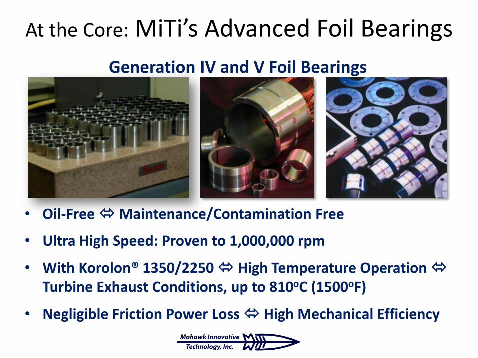
Generation IV and V Foil Bearings
At the Core: MiTi’s Advanced Foil Bearings
• Oil-Free Maintenance/Contamination Free
• Ultra High Speed: Proven to 1,000,000 rpm
• With Korolon® 1350/2250 High Temperature Operation Turbine Exhaust Conditions, up to 810oC (1500oF)
• Negligible Friction Power Loss High Mechanical Efficiency
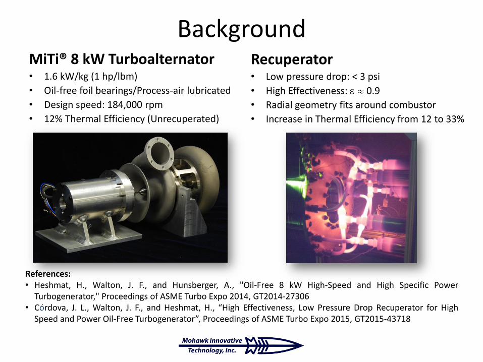
BackgroundMiTi® 8 kW Turboalternator• 1.6 kW/kg (1 hp/lbm)
• Oil-free foil bearings/Process-air lubricated
• Design speed: 184,000 rpm
• 12% Thermal Efficiency (Unrecuperated)
Recuperator• Low pressure drop: < 3 psi
• High Effectiveness: 0.9
• Radial geometry fits around combustor
• Increase in Thermal Efficiency from 12 to 33%
References:• Heshmat, H., Walton, J. F., and Hunsberger, A., "Oil-Free 8 kW High-Speed and High Specific Power
Turbogenerator," Proceedings of ASME Turbo Expo 2014, GT2014-27306• Córdova, J. L., Walton, J. F., and Heshmat, H., “High Effectiveness, Low Pressure Drop Recuperator for High
Speed and Power Oil-Free Turbogenerator”, Proceedings of ASME Turbo Expo 2015, GT2015-43718

Project Team
• Hooshang Heshmat, Ph.D.– Technical Director
– Principal Investigator
• James F. Walton II– Sr. Program Manager
• Jose L. Cordova, Ph.D.– Program Manager
– Project Engineer
• Hossein Ghezel-Ayagh, Ph.D.– FCE Lead
• Micah Casteel, Ph.D.
– Mechanical Engineer
• Stephen Jolly– Systems Design Engineer

Objective
• Develop a High Heat Transfer Effectiveness, Low Pressure Drop Ceramic Heat Exchanger for Application as Solid Oxide Fuel Cell Cathode (SOFC) Air Preheater.
– Possible Materials: Ceramics, Cermet, Hybrid Ceramics, Elastic Ceramics

Purpose of Heat Exchanger
• SOFC cathode requires a fresh air supply at ~700oC for operation.
• Anode exhaust contains CO and H2.
– These are post-combusted in a catalytic oxidizer, yielding high temperature heat.
– Heat is recovered in heat exchanger and used to preheat supplied air.
(Continued)

Motivation for Use of Ceramics
• Humidity in air supply causes metal alloys (e.g.: steels, nickel-based and other super-alloys) used in typical heat exchangers to release volatilized chromium.
– Chromium reacts with cathode materials to degrade cell voltage and ultimately poison cathode elements.
• Alternate materials (i.e., ceramics, cermets, hybrid ceramics, elastic ceramics) may offer best choice for SOFCs.

Overview of Approach
• Leverage MiTi’s Novel Gas Turbine Recuperator– Original application: 8 kW gas turbine-based turboalternator
• Turbine engine specifications, operating at 42 psi, allowed pressure drop of 3 to 5 psi.
– Attained 90% heat transfer effectiveness (measured) at engine operating conditions.
– Greater than Two-Fold Increase of Cycle Thermal Efficiency• from 12% to 30% (measured)
• Extend Technology to SOFC– Ceramic Materials
– Reduce pressure drop
Major Program Elements
1. Solid Oxide Fuel Cell Definition of Requirements
2. Heat Transfer Analysis and Heat Exchanger Sizing
3. Ceramic Materials Review and Selection
4. Fabrication of Heat Exchanger Prototype
5. Pressure drop and thermal performance testing
6. Integration to SOFC test facility
IDENTIFICATION OF TARGET SOFCAND PROTOTYPE REQUIREMENTS
Target Application: Solid Oxide Fuel Cell Operating Conditions

Target Application
• FuelCell Energy Inc.– Proof Of Concept (POC)
50 kWe SOFC
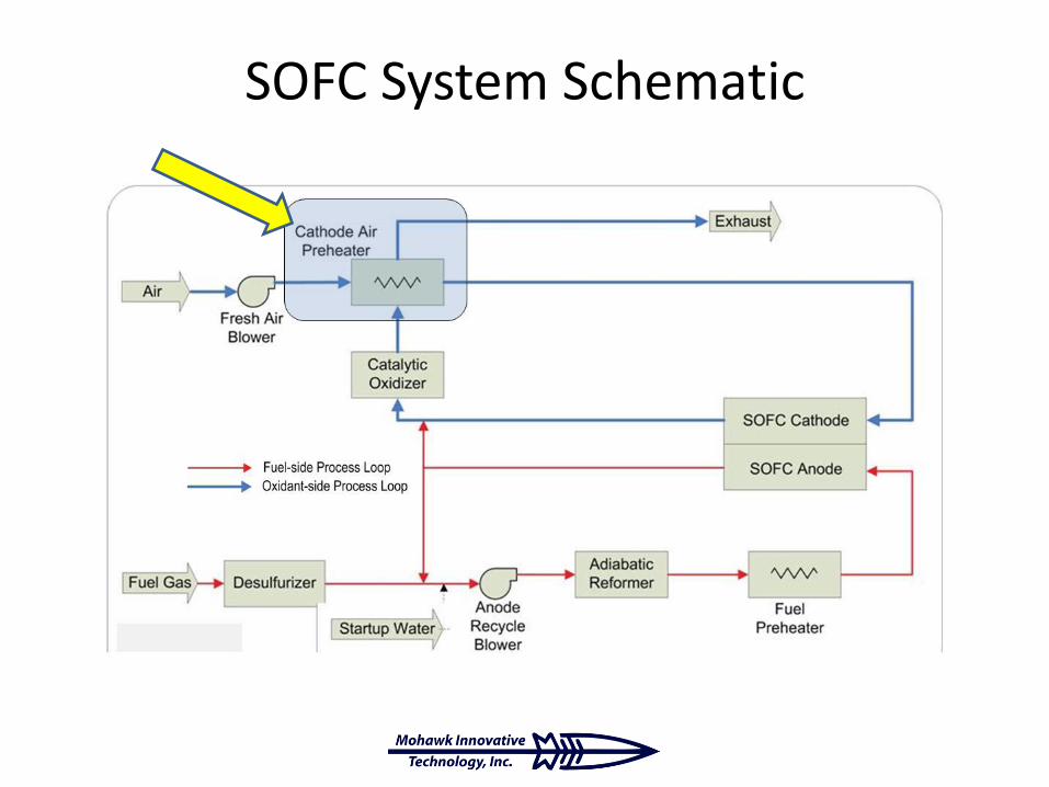
SOFC System Schematic

50 kWe POC Operating Conditions
• Required Preheater Heat Transfer:
Q = ṁ cp (Tairout – Tairin) ≈ 41 kW
• Total Allowable Pressure Drop:
ΔPtot = 3447.4 Pa (= 13.8 inH2O = 0.5 psi)
MiTi’S RECUPERATOR EXPERIENCE
Background
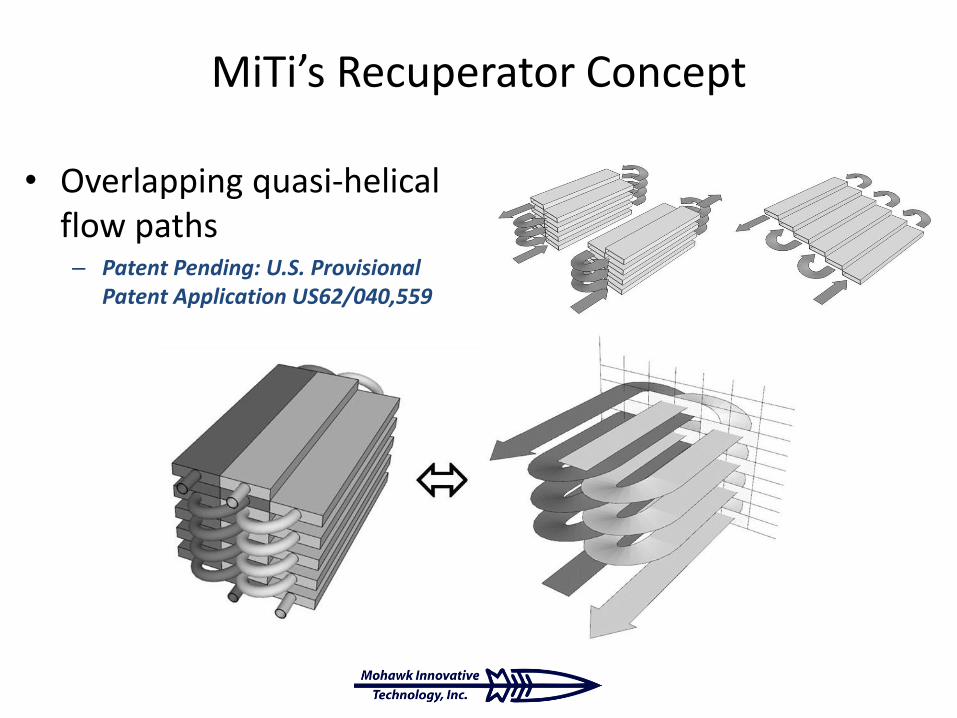
MiTi’s Recuperator Concept
• Overlapping quasi-helical flow paths– Patent Pending: U.S. Provisional
Patent Application US62/040,559

MiTi’s Recuperator Concept
Design allows to add or remove segments according to flow, pressure drop, or heat exchange rate requirements.
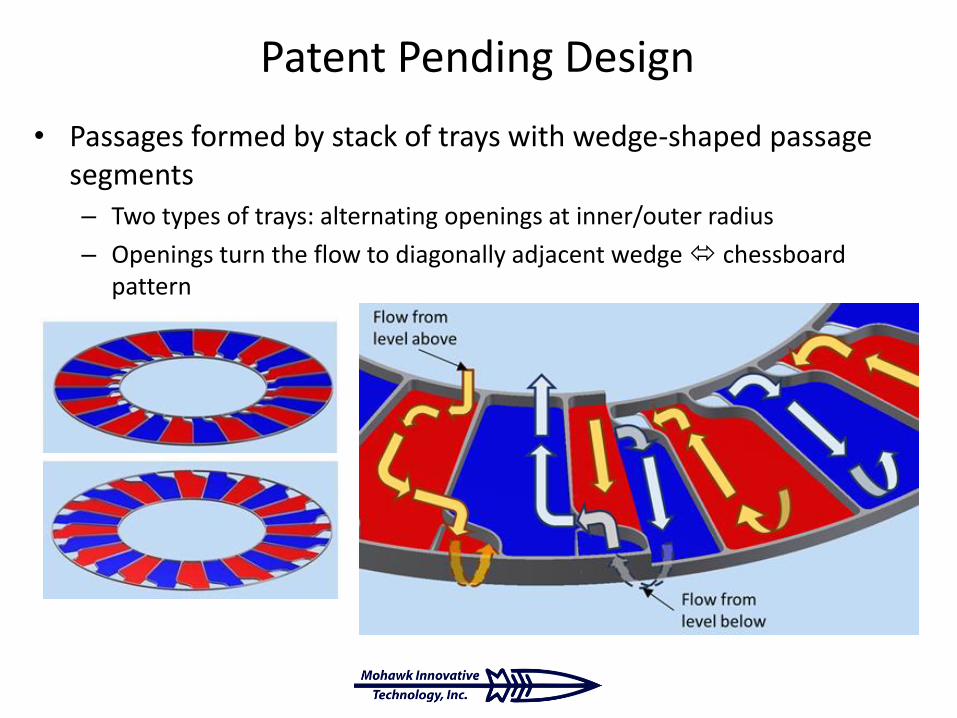
Patent Pending Design
• Passages formed by stack of trays with wedge-shaped passage segments– Two types of trays: alternating openings at inner/outer radius
– Openings turn the flow to diagonally adjacent wedge chessboard pattern

Recuperator Prototype

Experimental Performance
Pressure Drop (P vs. ṁ) Effectiveness ( vs. ṁ)
3/17/2017
𝜺𝑹 = 𝒎 𝒄𝒑 𝐡
𝑻𝐡,𝐢𝐧 − 𝑻𝐡,𝐨𝐮𝐭
𝒎 𝒄𝒑 𝐦𝐢𝐧𝑻𝐡,𝐢𝐧 − 𝑻𝐜,𝐢𝐧
= 𝒎 𝒄𝒑 𝐜
𝑻𝐜,𝐨𝐮𝐭 − 𝑻𝐜,𝐢𝐧
𝒎 𝒄𝒑 𝐦𝐢𝐧𝑻𝐡,𝐢𝐧 − 𝑻𝐜,𝐢𝐧

HEAT EXCHANGER DESIGNHeat Transfer Analysis and Heat Exchanger Sizing
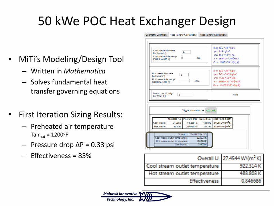
50 kWe POC Heat Exchanger Design
• MiTi’s Modeling/Design Tool– Written in Mathematica
– Solves fundamental heat transfer governing equations
• First Iteration Sizing Results:– Preheated air temperature
Tairout = 1200oF
– Pressure drop ΔP = 0.33 psi
– Effectiveness = 85%
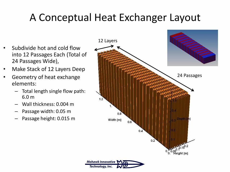
A Conceptual Heat Exchanger Layout
• Subdivide hot and cold flow into 12 Passages Each (Total of 24 Passages Wide),
• Make Stack of 12 Layers Deep
• Geometry of heat exchange elements:– Total length single flow path:
6.0 m
– Wall thickness: 0.004 m
– Passage width: 0.05 m
– Passage height: 0.015 m
24 Passages
12 Layers

MATERIAL SELECTION
Thermal Criterion for Material Selection
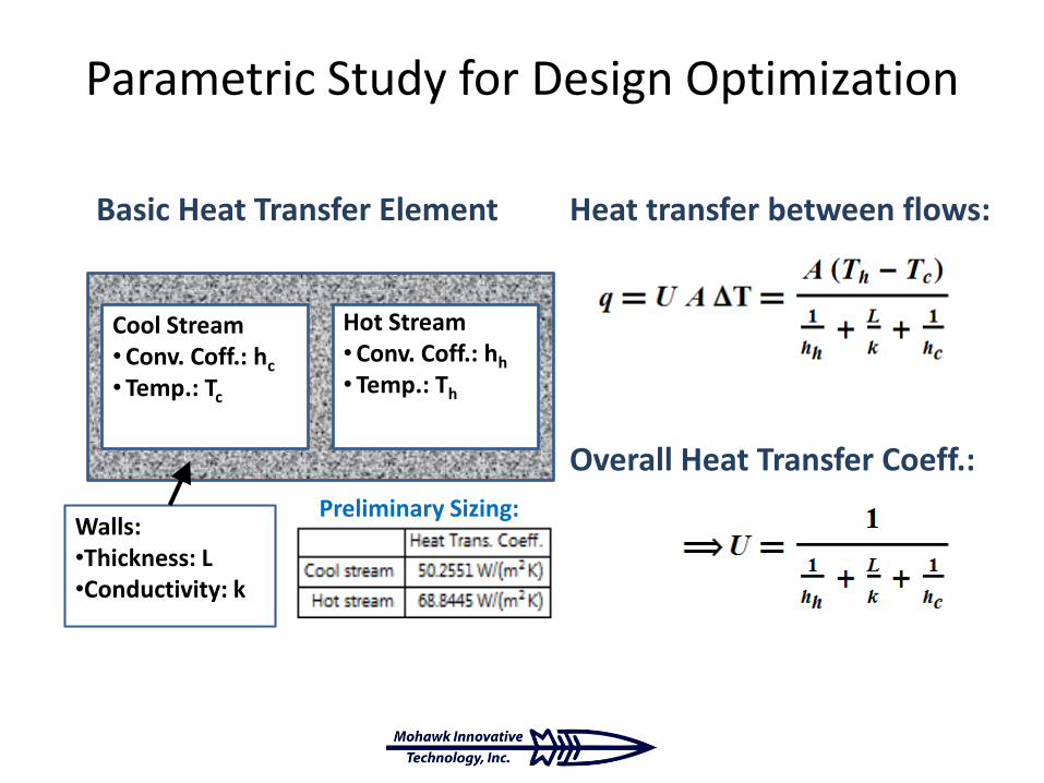
Parametric Study for Design Optimization
Heat transfer between flows:Basic Heat Transfer Element
Overall Heat Transfer Coeff.:
Cool Stream•Conv. Coff.: hc
• Temp.: Tc
Hot Stream•Conv. Coff.: hh
• Temp.: Th
Walls:•Thickness: L•Conductivity: k
Preliminary Sizing:

Effect of Wall Thermal Conductivity
Cu@1000KSiC@1000K
Inconel X-750@1000K
Alumina
Korolon®1350
Zirconia
Increasing Overall Heat Transfer Coefficient U
At SOFC operating conditions and practical wall thickness (L < 0.005 m), the wallsbehave as thermally thin, and the overall heat transfer coefficient is nearlyindependent of wall conductivity, therefore, the choice of material is irrelevant.

Choice Based on Ease of Fabrication
• Explored several commercially-available materials
– Castable/Moldable
– Green-State Machinable
– Fired-State Machinable
• Fabricated and tested samples
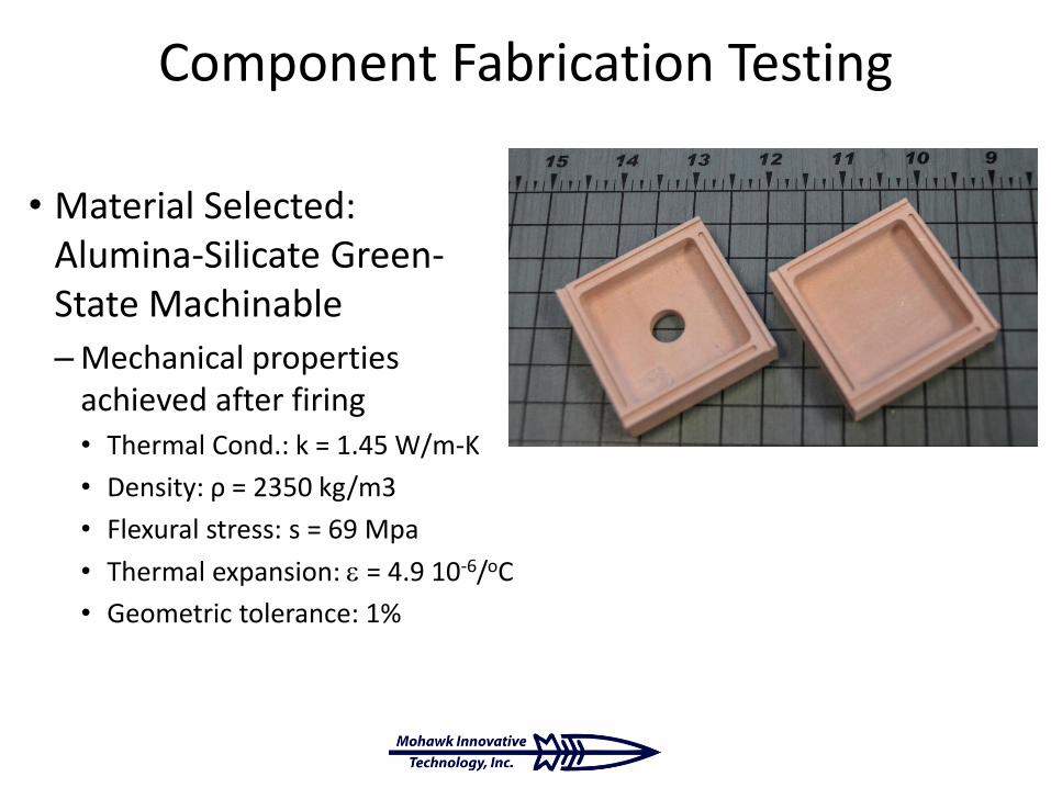
Component Fabrication Testing
• Material Selected: Alumina-Silicate Green-State Machinable
–Mechanical properties achieved after firing• Thermal Cond.: k = 1.45 W/m-K
• Density: ρ = 2350 kg/m3
• Flexural stress: s = 69 Mpa
• Thermal expansion: = 4.9 10-6/oC
• Geometric tolerance: 1%
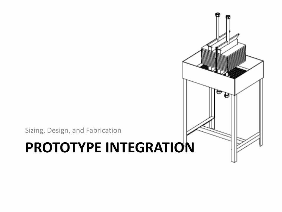
PROTOTYPE INTEGRATION
Sizing, Design, and Fabrication

5 kW Prototype Operating Conditions
• ṁ = 8 g/sec (1 lbm/min)
• Required Heat Transfer: – Q = ṁ cp (Tairout – Tairin) 5.2 kW
• Total Allowable Pressure Drop:– ΔPtot < 3.45 kPa (0.5 psi)
• With all temperatures pre-determined, the effectiveness is constrained to be = 73%

MiTi® Cathode Air Preheater

Repeating Unit

Assembled Prototype

PROTOTYPE PERFORMANCE TESTING
Effectiveness and Pressure Drop Tests
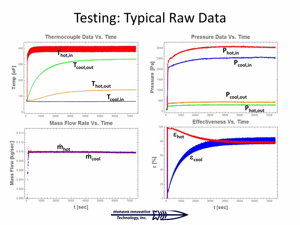
Testing: Typical Raw Data
Thot,in
Tcool,out
Thot,out
Tcool,in
Phot,in
Pcool,in
Pcool,out
Phot,out
ṁhot
ṁcool
hot
cool

Pressure Drop vs. Mass Flow
Total ΔP at operating condition is about 6 kPa (0.87 psi), outside of design target…
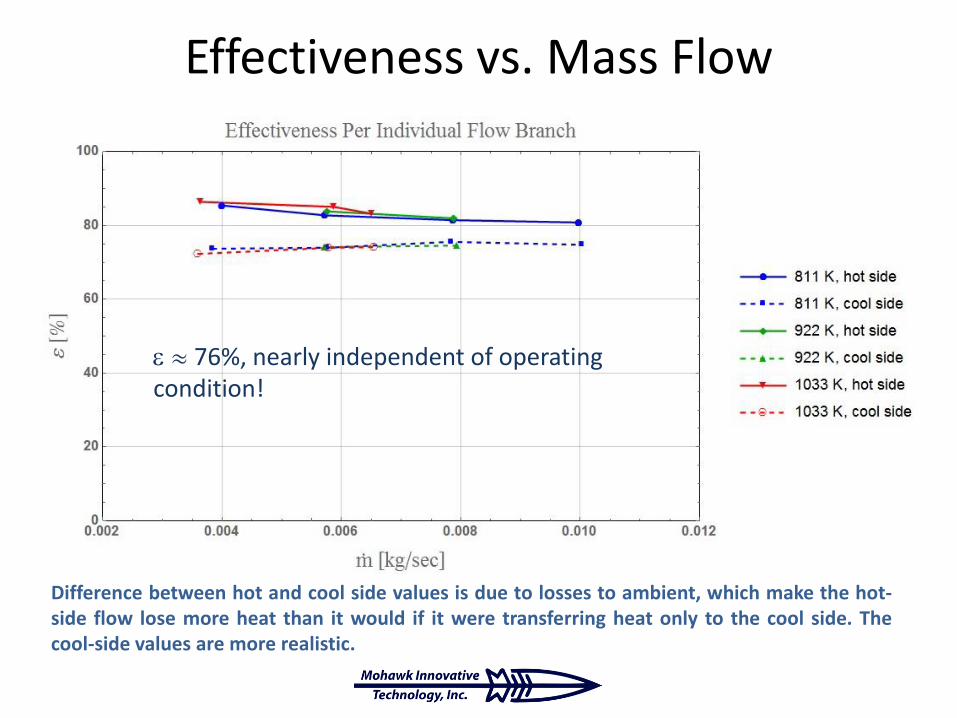
Effectiveness vs. Mass Flow
Difference between hot and cool side values is due to losses to ambient, which make the hot-side flow lose more heat than it would if it were transferring heat only to the cool side. Thecool-side values are more realistic.
76%, nearly independent of operating condition!
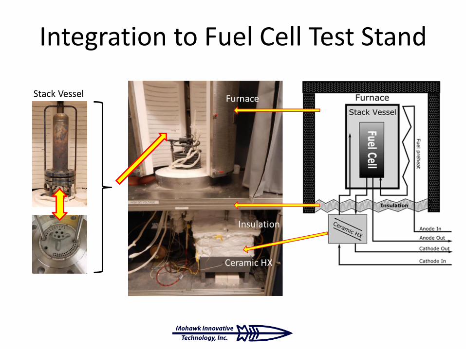
Integration to Fuel Cell Test Stand
Stack Vessel

Closing Remarks
• Successfully Designed and Prototyped Ceramic Heat Exchanger for Fuel Cell Application– Modular Design Allows Great Flexibility for
Application-Specific Performance Matching
• Installed Heat Exchanger into Fuel Cell Test Stand
• Immediate Next Steps:– FCE data collection with fuel cell
• Future Steps– Simplify Manufacturability

Acknowledgements
• This material is based upon work supported by the Department of Energy under Award Number DE-FE0024090.
• The authors particularly acknowledge the support of Dr. Sydni Credle, at the Crosscutting Research Division, National Energy Technology Laboratory (NETL).
• We also acknowledge the technical advice provided by Dr. Hossein Ghezel-Ayagh and his team at Fuel Cell Energy, Inc.

Publication Citation
• Córdova J, Heshmat H. Development of a Ceramic Heat Exchanger for Application as Solid Oxide Fuel Cell Cathode Air Preheater. ASME. ASME Power Conference, ASME 2016 Power Conference ():V001T04A006. doi:10.1115/POWER2016-59333.
