high voltage dc relay - cotronics bvcotronics.nl/wp...gpr-gpr-m-gpr-h-relay_1807.pdf · gpr-m/gpr-h...
TRANSCRIPT
High VoltageDC Relay
2 - High Voltage DC Relay
Leading Innovation, Creating TomorrowWith over 30 years of experience in electric power and automation solutions, we provide quality products for industrial applications.LSIS in cooperation with customers designs advanced DC solutions with innovative technology that enable them to bring next generation products to the market.
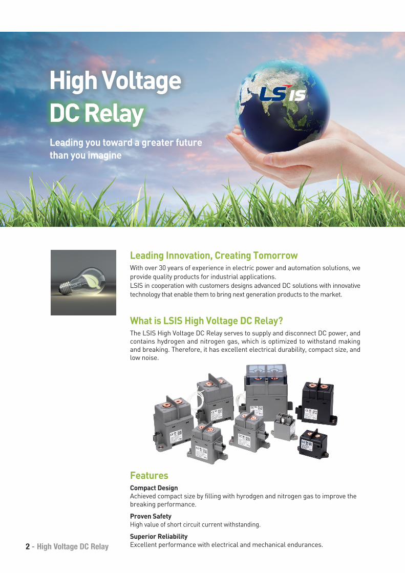
High Voltage High Voltage DC RelayDC RelayLeading you toward a greater futurethan you imagine
What is LSIS High Voltage DC Relay?The LSIS High Voltage DC Relay serves to supply and disconnect DC power, and contains hydrogen and nitrogen gas, which is optimized to withstand making and breaking. Therefore, it has excellent electrical durability, compact size, and low noise.
FeaturesCompact DesignAchieved compact size by filling with hyrodgen and nitrogen gas to improve the breaking performance.
Proven SafetyHigh value of short circuit current withstanding.
Superior ReliabilityExcellent performance with electrical and mechanical endurances.
LSIS - 3
H2
gas
I I
H2
gasArcF F
I I
H2
gas
I I
H2
gasArcF F
I I
LSIS - High Voltage DC Relay
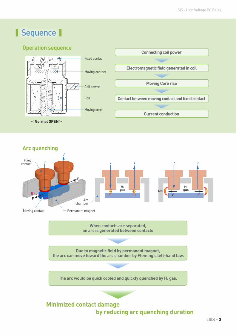
Connecting coil power
Electromagnetic field generated in coil
Moving Core rise
Contact between moving contact and fixed contact
Current conduction
When contacts are separated,an arc is generated between contacts
Due to magnetic field by permanent magnet, the arc can move toward the arc chamber by Fleming’s left-hand law.
The arc would be quick cooled and quickly quenched by H2 gas.
Minimized contact damage by reducing arc quenching duration
Sequence
Operation sequence
Arc quenching
< Normal OPEN >
Fixed contact
Moving contact
Coil
Permanent magnet
Fixed contact
Arc chamber
Moving contact
Moving core
Coil power
I
F
I
FB
4 - High Voltage DC Relay
Ordering Information & Option detail
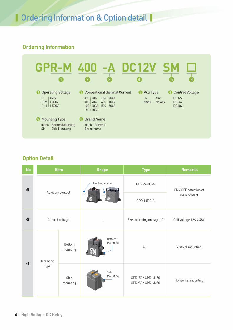
Ordering Information
➍ Control VoltageDC12VDC24VDC48V
➊ Operating VoltageR 450VR-M 1,000VR-H 1,500V~
➌ Aux Type-A Aux.blank No Aux.
➎ Mounting Typeblank Bottom MountingSM Side Mounting
➏ Brand Nameblank GeneralBrand name
➋ Conventional thermal Current010 10A 250 250A 040 40A 400 400A100 100A 500 500A150 150A
GPR-M➊
400➋
DC12V➍
SM➎
-A➌ ➏
Option Detail
No Item Shape Type Remarks
➌Auxiliary contact
GPR-M400-A
ON / OFF detection of main contact
GPR-H500-A
➍ Control voltage - See coil rating on page 10 Coil voltage 12/24/48V
➎Mounting
type
Bottom mounting
ALL Vertical mounting
Side mounting
GPR150 / GPR-M150GPR250 / GPR-M250
Horizontal mounting
Side Mounting
Auxiliary contact
Bottom Mounting
LSIS - 5
LSIS - High Voltage DC Relay
*
PowerGrid
Inverter
Inverter
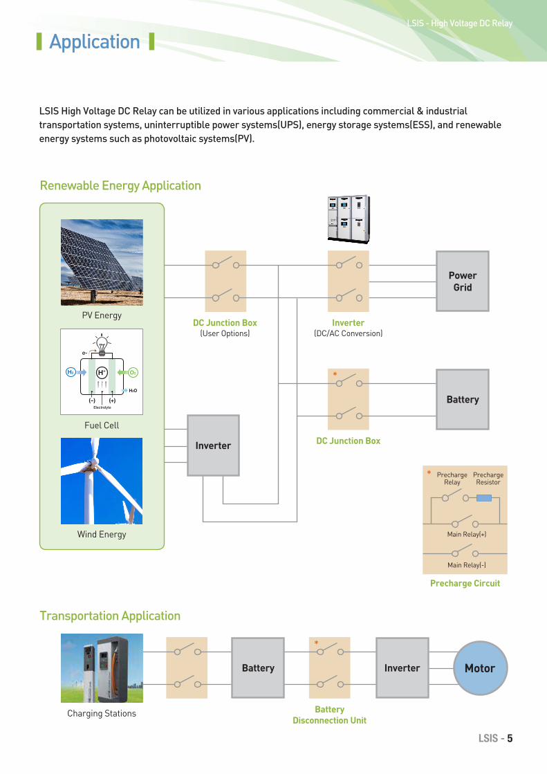
LSIS High Voltage DC Relay can be utilized in various applications including commercial & industrial transportation systems, uninterruptible power systems(UPS), energy storage systems(ESS), and renewable energy systems such as photovoltaic systems(PV).
Transportation Application
Application
Renewable Energy Application
Charging Stations
DC Junction Box(User Options)
Inverter(DC/AC Conversion)
Battery Disconnection Unit
DC Junction Box
*
Battery
Battery
Motor
Main Relay(+)
Precharge Relay
Precharge Resistor
Main Relay(-)
Precharge Circuit
*
PV Energy
Wind Energy
H2 H+
(-)
O2
(+)
H2O
Electrolyte
e-
Fuel Cell
6 - High Voltage DC Relay
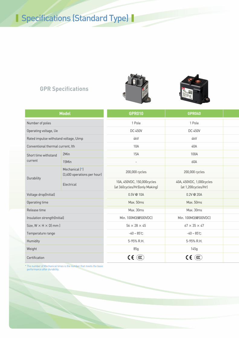
GPR Specifications
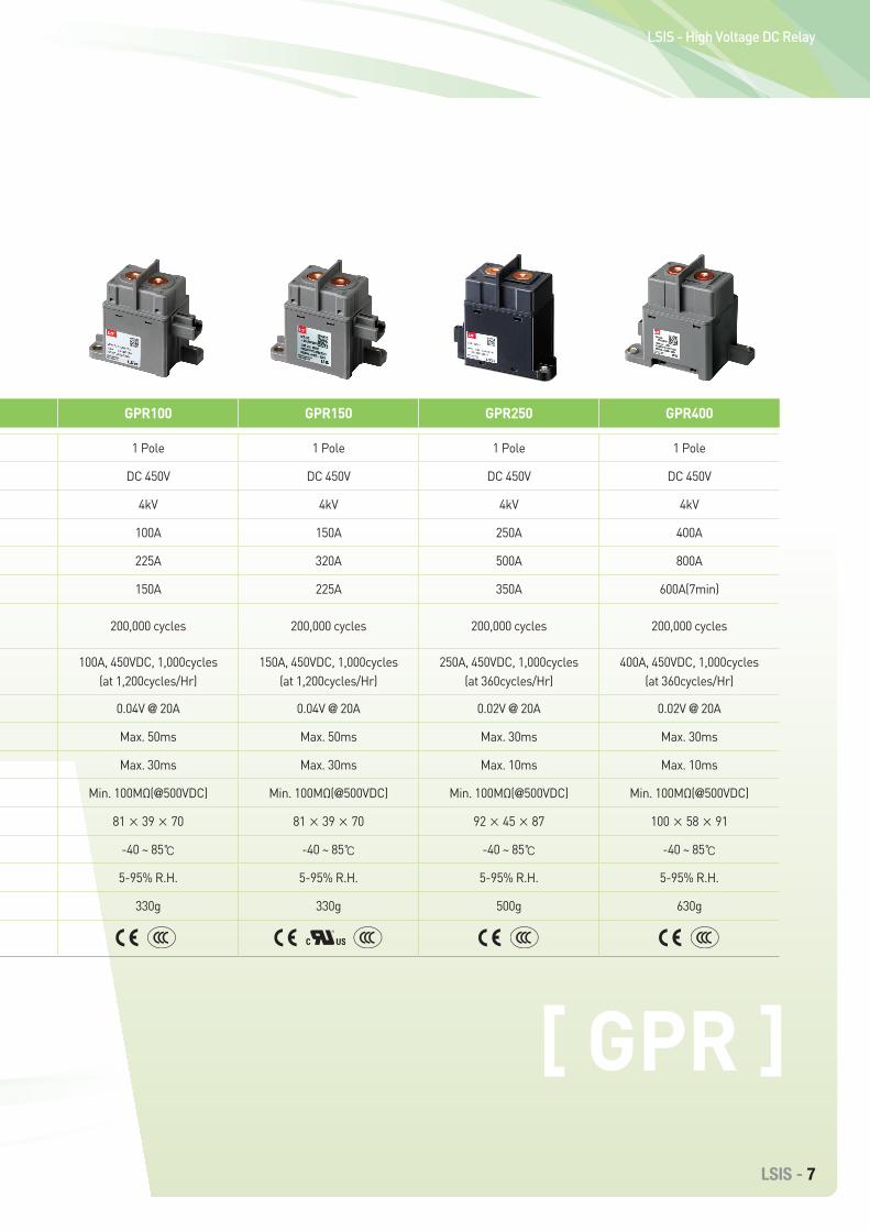
Model GPR010 GPR040 GPR100 GPR150 GPR250 GPR400
Number of poles 1 Pole 1 Pole 1 Pole 1 Pole 1 Pole 1 Pole
Operating voltage, Ue DC 450V DC 450V DC 450V DC 450V DC 450V DC 450V
Rated impulse withstand voltage, Uimp 4kV 4kV 4kV 4kV 4kV 4kV
Conventional thermal current, Ith 10A 40A 100A 150A 250A 400A
Short time withstand current
2Min 15A 100A 225A 320A 500A 800A
15Min - 60A 150A 225A 350A 600A(7min)
Durability
Mechanical (*)(3,600 operations per hour)
200,000 cycles 200,000 cycles 200,000 cycles 200,000 cycles 200,000 cycles 200,000 cycles
Electrical10A, 450VDC, 150,000cycles
(at 360cycles/Hr)(only Making)40A, 450VDC, 1,000cycles
(at 1,200cycles/Hr)100A, 450VDC, 1,000cycles
(at 1,200cycles/Hr)150A, 450VDC, 1,000cycles
(at 1,200cycles/Hr)250A, 450VDC, 1,000cycles
(at 360cycles/Hr)400A, 450VDC, 1,000cycles
(at 360cycles/Hr)
Voltage drop(Initial) 0.5V @ 10A 0.2V @ 20A 0.04V @ 20A 0.04V @ 20A 0.02V @ 20A 0.02V @ 20A
Operating time Max. 50ms Max. 50ms Max. 50ms Max. 50ms Max. 30ms Max. 30ms
Release time Max. 30ms Max. 30ms Max. 30ms Max. 30ms Max. 10ms Max. 10ms
Insulation strength(Initial) Min. 100MΩ(@500VDC) Min. 100MΩ(@500VDC) Min. 100MΩ(@500VDC) Min. 100MΩ(@500VDC) Min. 100MΩ(@500VDC) Min. 100MΩ(@500VDC)
Size, W × H × D( mm ) 56 × 28 × 45 67 × 35 × 47 81 × 39 × 70 81 × 39 × 70 92 × 45 × 87 100 × 58 × 91
Temperature range -40 ~ 85℃ -40 ~ 85℃ -40 ~ 85℃ -40 ~ 85℃ -40 ~ 85℃ -40 ~ 85℃
Humidity 5-95% R.H. 5-95% R.H. 5-95% R.H. 5-95% R.H. 5-95% R.H. 5-95% R.H.
Weight 85g 145g 330g 330g 500g 630g
Certification
Specifications (Standard Type)
* The number of Mechanical times is the number that meets the basic performance after durability.
LSIS - 7
LSIS - High Voltage DC Relay
Model GPR010 GPR040 GPR100 GPR150 GPR250 GPR400
Number of poles 1 Pole 1 Pole 1 Pole 1 Pole 1 Pole 1 Pole
Operating voltage, Ue DC 450V DC 450V DC 450V DC 450V DC 450V DC 450V
Rated impulse withstand voltage, Uimp 4kV 4kV 4kV 4kV 4kV 4kV
Conventional thermal current, Ith 10A 40A 100A 150A 250A 400A
Short time withstand current
2Min 15A 100A 225A 320A 500A 800A
15Min - 60A 150A 225A 350A 600A(7min)
Durability
Mechanical (*)(3,600 operations per hour)
200,000 cycles 200,000 cycles 200,000 cycles 200,000 cycles 200,000 cycles 200,000 cycles
Electrical10A, 450VDC, 150,000cycles
(at 360cycles/Hr)(only Making)40A, 450VDC, 1,000cycles
(at 1,200cycles/Hr)100A, 450VDC, 1,000cycles
(at 1,200cycles/Hr)150A, 450VDC, 1,000cycles
(at 1,200cycles/Hr)250A, 450VDC, 1,000cycles
(at 360cycles/Hr)400A, 450VDC, 1,000cycles
(at 360cycles/Hr)
Voltage drop(Initial) 0.5V @ 10A 0.2V @ 20A 0.04V @ 20A 0.04V @ 20A 0.02V @ 20A 0.02V @ 20A
Operating time Max. 50ms Max. 50ms Max. 50ms Max. 50ms Max. 30ms Max. 30ms
Release time Max. 30ms Max. 30ms Max. 30ms Max. 30ms Max. 10ms Max. 10ms
Insulation strength(Initial) Min. 100MΩ(@500VDC) Min. 100MΩ(@500VDC) Min. 100MΩ(@500VDC) Min. 100MΩ(@500VDC) Min. 100MΩ(@500VDC) Min. 100MΩ(@500VDC)
Size, W × H × D( mm ) 56 × 28 × 45 67 × 35 × 47 81 × 39 × 70 81 × 39 × 70 92 × 45 × 87 100 × 58 × 91
Temperature range -40 ~ 85℃ -40 ~ 85℃ -40 ~ 85℃ -40 ~ 85℃ -40 ~ 85℃ -40 ~ 85℃
Humidity 5-95% R.H. 5-95% R.H. 5-95% R.H. 5-95% R.H. 5-95% R.H. 5-95% R.H.
Weight 85g 145g 330g 330g 500g 630g
Certification
[ GPR ]
8 - High Voltage DC Relay
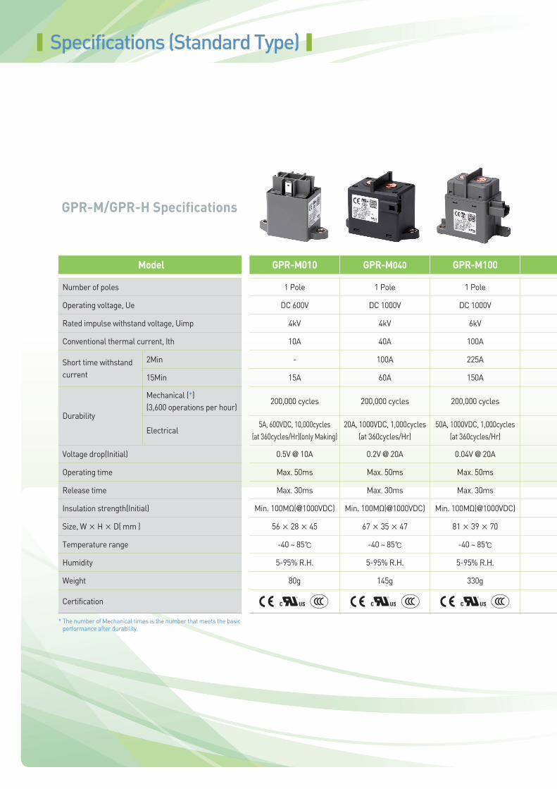
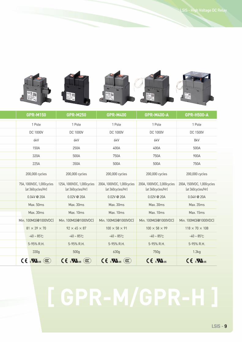
GPR-M/GPR-H Specifications
Model GPR-M010 GPR-M040 GPR-M100 GPR-M150 GPR-M250 GPR-M400 GPR-M400-A GPR-H500-A
Number of poles 1 Pole 1 Pole 1 Pole 1 Pole 1 Pole 1 Pole 1 Pole 1 Pole
Operating voltage, Ue DC 600V DC 1000V DC 1000V DC 1000V DC 1000V DC 1000V DC 1000V DC 1500V
Rated impulse withstand voltage, Uimp 4kV 4kV 6kV 6kV 6kV 6kV 6kV 8kV
Conventional thermal current, Ith 10A 40A 100A 150A 250A 400A 400A 500A
Short time withstand current
2Min - 100A 225A 320A 500A 750A 750A 900A
15Min 15A 60A 150A 225A 350A 500A 500A 750A
Durability
Mechanical (*)(3,600 operations per hour)
200,000 cycles 200,000 cycles 200,000 cycles 200,000 cycles 200,000 cycles 200,000 cycles 200,000 cycles 200,000 cycles
Electrical5A, 600VDC, 10,000cycles
(at 360cycles/Hr)(only Making)20A, 1000VDC, 1,000cycles
(at 360cycles/Hr)50A, 1000VDC, 1,000cycles
(at 360cycles/Hr)75A, 1000VDC, 1,000cycles
(at 360cycles/Hr)125A, 1000VDC, 1,000cycles
(at 360cycles/Hr)200A, 1000VDC, 1,000cycles
(at 360cycles/Hr)200A, 1000VDC, 3,000cycles
(at 360cycles/Hr)200A, 1500VDC, 1,000cycles
(at 360cycles/Hr)
Voltage drop(Initial) 0.5V @ 10A 0.2V @ 20A 0.04V @ 20A 0.04V @ 20A 0.02V @ 20A 0.02V @ 20A 0.02V @ 20A 0.04V @ 20A
Operating time Max. 50ms Max. 50ms Max. 50ms Max. 50ms Max. 30ms Max. 30ms Max. 30ms Max. 35ms
Release time Max. 30ms Max. 30ms Max. 30ms Max. 30ms Max. 10ms Max. 10ms Max. 10ms Max. 15ms
Insulation strength(Initial) Min. 100MΩ(@1000VDC) Min. 100MΩ(@1000VDC) Min. 100MΩ(@1000VDC) Min. 100MΩ(@1000VDC) Min. 100MΩ(@1000VDC) Min. 100MΩ(@1000VDC) Min. 100MΩ(@1000VDC) Min. 100MΩ(@1000VDC)
Size, W × H × D( mm ) 56 × 28 × 45 67 × 35 × 47 81 × 39 × 70 81 × 39 × 70 92 × 45 × 87 100 × 58 × 91 100 × 58 × 99 118 × 70 × 108
Temperature range -40 ~ 85℃ -40 ~ 85℃ -40 ~ 85℃ -40 ~ 85℃ -40 ~ 85℃ -40 ~ 85℃ -40 ~ 85℃ -40 ~ 85℃
Humidity 5-95% R.H. 5-95% R.H. 5-95% R.H. 5-95% R.H. 5-95% R.H. 5-95% R.H. 5-95% R.H. 5-95% R.H.
Weight 80g 145g 330g 330g 500g 630g 750g 1.3kg
Certification
Specifications (Standard Type)
* The number of Mechanical times is the number that meets the basic performance after durability.
LSIS - 9
LSIS - High Voltage DC Relay
Model GPR-M010 GPR-M040 GPR-M100 GPR-M150 GPR-M250 GPR-M400 GPR-M400-A GPR-H500-A
Number of poles 1 Pole 1 Pole 1 Pole 1 Pole 1 Pole 1 Pole 1 Pole 1 Pole
Operating voltage, Ue DC 600V DC 1000V DC 1000V DC 1000V DC 1000V DC 1000V DC 1000V DC 1500V
Rated impulse withstand voltage, Uimp 4kV 4kV 6kV 6kV 6kV 6kV 6kV 8kV
Conventional thermal current, Ith 10A 40A 100A 150A 250A 400A 400A 500A
Short time withstand current
2Min - 100A 225A 320A 500A 750A 750A 900A
15Min 15A 60A 150A 225A 350A 500A 500A 750A
Durability
Mechanical (*)(3,600 operations per hour)
200,000 cycles 200,000 cycles 200,000 cycles 200,000 cycles 200,000 cycles 200,000 cycles 200,000 cycles 200,000 cycles
Electrical5A, 600VDC, 10,000cycles
(at 360cycles/Hr)(only Making)20A, 1000VDC, 1,000cycles
(at 360cycles/Hr)50A, 1000VDC, 1,000cycles
(at 360cycles/Hr)75A, 1000VDC, 1,000cycles
(at 360cycles/Hr)125A, 1000VDC, 1,000cycles
(at 360cycles/Hr)200A, 1000VDC, 1,000cycles
(at 360cycles/Hr)200A, 1000VDC, 3,000cycles
(at 360cycles/Hr)200A, 1500VDC, 1,000cycles
(at 360cycles/Hr)
Voltage drop(Initial) 0.5V @ 10A 0.2V @ 20A 0.04V @ 20A 0.04V @ 20A 0.02V @ 20A 0.02V @ 20A 0.02V @ 20A 0.04V @ 20A
Operating time Max. 50ms Max. 50ms Max. 50ms Max. 50ms Max. 30ms Max. 30ms Max. 30ms Max. 35ms
Release time Max. 30ms Max. 30ms Max. 30ms Max. 30ms Max. 10ms Max. 10ms Max. 10ms Max. 15ms
Insulation strength(Initial) Min. 100MΩ(@1000VDC) Min. 100MΩ(@1000VDC) Min. 100MΩ(@1000VDC) Min. 100MΩ(@1000VDC) Min. 100MΩ(@1000VDC) Min. 100MΩ(@1000VDC) Min. 100MΩ(@1000VDC) Min. 100MΩ(@1000VDC)
Size, W × H × D( mm ) 56 × 28 × 45 67 × 35 × 47 81 × 39 × 70 81 × 39 × 70 92 × 45 × 87 100 × 58 × 91 100 × 58 × 99 118 × 70 × 108
Temperature range -40 ~ 85℃ -40 ~ 85℃ -40 ~ 85℃ -40 ~ 85℃ -40 ~ 85℃ -40 ~ 85℃ -40 ~ 85℃ -40 ~ 85℃
Humidity 5-95% R.H. 5-95% R.H. 5-95% R.H. 5-95% R.H. 5-95% R.H. 5-95% R.H. 5-95% R.H. 5-95% R.H.
Weight 80g 145g 330g 330g 500g 630g 750g 1.3kg
Certification
[ GPR-M/GPR-H ]
10 - High Voltage DC Relay
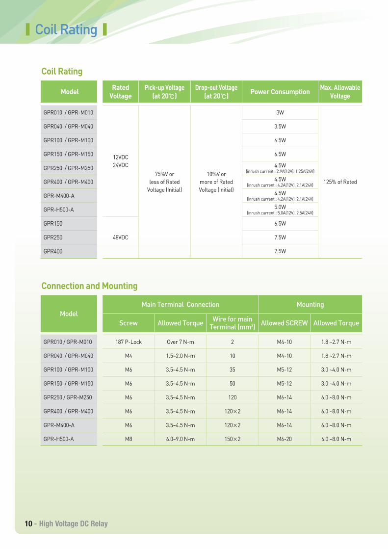
Coil Rating
Model RatedVoltage
Pick-up Voltage(at 20℃)
Drop-out Voltage(at 20℃) Power Consumption Max. Allowable
Voltage
GPR010 / GPR-M010
12VDC24VDC
75%V or less of Rated
Voltage (Initial)
10%V or more of Rated Voltage (Initial)
3W
125% of Rated
GPR040 / GPR-M040 3.5W
GPR100 / GPR-M100 6.5W
GPR150 / GPR-M150 6.5W
GPR250 / GPR-M250 4.5W(inrush current : 2.9A(12V), 1.25A(24V)
GPR400 / GPR-M400 4.5W(inrush current : 4.2A(12V), 2.1A(24V)
GPR-M400-A 4.5W(inrush current : 4.2A(12V), 2.1A(24V)
GPR-H500-A 5.0W(inrush current : 5.0A(12V), 2.5A(24V)
GPR150
48VDC
6.5W
GPR250 7.5W
GPR400 7.5W
ModelMain Terminal Connection Mounting
Screw Allowed Torque Wire for main Terminal (mm2) Allowed SCREW Allowed Torque
GPR010 / GPR-M010 187 P-Lock Over 7 N-m 2 M4-10 1.8 ~2.7 N-m
GPR040 / GPR-M040 M4 1.5~2.0 N-m 10 M4-10 1.8 ~2.7 N-m
GPR100 / GPR-M100 M6 3.5~4.5 N-m 35 M5-12 3.0 ~4.0 N-m
GPR150 / GPR-M150 M6 3.5~4.5 N-m 50 M5-12 3.0 ~4.0 N-m
GPR250 / GPR-M250 M6 3.5~4.5 N-m 120 M6-14 6.0 ~8.0 N-m
GPR400 / GPR-M400 M6 3.5~4.5 N-m 120×2 M6-14 6.0 ~8.0 N-m
GPR-M400-A M6 3.5~4.5 N-m 120×2 M6-14 6.0 ~8.0 N-m
GPR-H500-A M8 6.0~9.0 N-m 150×2 M6-20 6.0 ~8.0 N-m
Coil Rating
Connection and Mounting
LSIS - 11
LSIS - High Voltage DC Relay
Precautions
ApplicationNotes
Specification range• Please use it according to specification range such as coil rating, mounting information. Otherwise it
may result in overheating or malfunction.
Installation and maintenance• If power is applied to the relay main contact, it may cause electric shock. Never touch it. During
installation, maintenance and troubleshooting, the power to the relay must be disconnected.
Connection• Incorrect connection may cause malfunction, overheating or fire.
Fail-safe• It could be dangerous, when welding or sticking to contacts occurs. So, take double safety
precautions and make sure that operation is foolproof.
Polarity• Relays have polarity. Check the polarity indicated on the housing and connect. If connected in the
opposite polarity, the electric durability performance can not be guaranteed.• Relay coils with PCBs are polarized. Check the indicated polarity and connect. If connected in the
opposite polarity, the relay will not operate.
Magnetism• If the relays are in close contact to each other or installed close to strong magnetic parts such as a
motor or a speaker, their operating characteristics may change or malfunction may occur. Therefore, check the magnetic effects of the actual installation and operating conditions.
Vibration / shock• To maintain initial performance, do not apply physical shock or drop the relay. Do not use dropped
products. Use shock absorbers during transportation.• The relay is designed not to be seperated under normal use conditions. To maintain initial
performance, do not disassemble the case. If the case is removed, relay performance can not be guaranteed.
Temperature• Condensation may also occur at contacts if the relay is used at temperatures below 0 ° C or in an
environment where the ambient temperature changes rapidly below zero. This condensation can delay operation time or interfere in operation of the relay.
• If the relay is operated continuously, the coil temperature may rise and the operating voltage may rise.
Coil voltage• If you apply coil voltage very slowly, it may cause an operation error. Therefore, apply the coil voltage quickly.
Mounting conditions• When exposed to high temperature or high humidity or to an environment containing organic or
sulphide gas for a long time (including shipping period), sulfide or oxide film may form on the surface of the contacts and cause poor contact, and malfunction. Please check the environment when you transport the product.
• Do not use the product in an environment where the main terminals may be exposed to foreign substances such as organic solvents (eg alcohol, benzene, thinner) or strong alkalis (eg ammonia, caustic soda). It may cause abnormal heat at the terminal part.
• This product is not waterproof. If you install it in a place where waterproofing is required, please find a way to meet your requirements.
Additional information• The reverse surge voltage generated by the coil of the relay may cause burnout of the load element.
Therefore, take measures to prevent reverse surge voltage. Do not use DIODE because the operation time of relay is delayed and electrical performance is degraded.
• When using a capacitive load (C-load), we recommend applying a precharge circuit so that the inrush current does not exceed the rated current.
• Electrical performance has been verified without L load, and electrical life can be shortened if you use L load.• When checking the conduction of the main contact, apply the minimum voltage (DC24V) and current
(1A) to the main contact. • To check the auxiliary contact conduction, apply DC5V 1mA ~ DC30V 100mA.
12 - High Voltage DC Relay
Selection of Relay Type
For the proper use of a relay, you must not only be well informed of the characteristics of the relay and service conditions to determine whether the selected one fits for the conditions for application, but also fully understand the specifications of coil and contact, operate time, mechanical characteristics, and other conditions for the relay to be used. Please refer to the table below for details and considerations for selection.
Items Details Considerations for Selection
Pick-up Voltage(Current)
The value at which a relay should function when increasing the voltage to an unoperated relay.
- Select a relay by considering a power supply ripple
- Specifically take into account ambient temperature, coil temperature, and hot start
- Be careful with the voltage drop when using the relay in conjunction with semiconductors
- Be careful with the voltage drop when starting up
Drop-out Voltage(Current)
The value at which a relay should revert to the unoperated state when decreasing the voltage to an operated relay.
Maximum ContinuousVoltage
The maximum allowable voltage to be continuously applied to the coil without causing damage. Short duration spikes of a higher voltage can be tolerated, but you must consult with the manufacturer above all.
Coil Resistance The DC resistance of the coil of DC type relays.
Temperature Rise
If power is supplied to coil, the coil's temperature is increased and saturated. Temperature rise refers to the difference between the temperatures before and after the power application to the coil.
Contact Rating The allowable rated voltage and current.- Note that the life of relay is
balanced with that of the device in which the relay is embedded.
- If often exposed to high temperature, the rated life of the relay may be reduced. It is required to test the life in an actual environment.
- Test and review need to be performed with actual load and application under an actual environment.
Contact Material Material that forms contacts.
LifeThe minimum number of times a relay can be operated under the normal condition while contacts are switching specific load.
ContactResistance
The value combined together the resistance produced when contacts touch each other, that of terminals, and that of contact spring.
Operating TimeThe time elapsed since power is first supplied to the coil until the open contacts are normally closed, excluding bounce time.
- Note that the operate time and bounce time may be changed according to the ambient temperature and applied voltage.
- Note that bounce time is not excluded from both operate time and release time.
- Note that switching life is affected by switching frequency.
Release TimeThe time elapsed since power is cut off from the coil until the normally closed contacts are reclosed, excluding bounce time.
Bounce TimeThe phenomenon that contacts intermittently switches on and off as movable parts and contacts collide.
SwitchingFrequency
The frequency of switching that repeats operations while satisfying the electrical life or mechanical life through the application of a pulse train to the operating coil at the rated voltage.
Operate Tim
eC
ontactC
oil
LSIS - 13
LSIS - High Voltage DC Relay
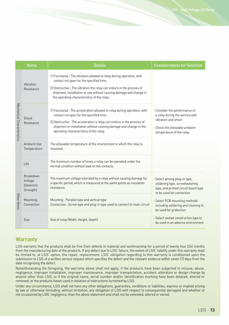
Items Details Considerations for Selection
VibrationResistance
1) Functional : The vibration allowed to relay during operation, with contact not open for the specified time.
2) Destructive : The vibration the relay can endure in the process of shipment, installation or use without causing damage and change in the operating characteristics of the relay.
- Consider the performance of a relay during the service with vibration and shock
- Check the allowable ambient temperature of the relay.
Shock Resistance
1) Functional : The acceleration allowed to relay during operation, with contact not open for the specified time.
2) Destructive : The acceleration a relay can endure in the process of shipment or installation without causing damage and change in the operating characteristics of the relay.
Ambient Use Temperature
The allowable temperature of the environment in which the relay is mounted.
LifeThe minimum number of times a relay can be operated under the normal condition without load on the contacts.
Breakdown Voltage(Dielectric Strength)
The maximum voltage tolerated by a relay without causing damage for a specific period, which is measured at the same points as insulation resistance.
- Select among plug-in type, soldering type, screwfastening type, and printed circuit board type to be used for connection
- Select PCB mounting methods including soldering and cleaning to be used for protection
- Select sealed construction type to be used in an adverse environment
Mounting, Connection
Mounting : Parallel type and vertical typeConnection : Screw type and plug-in type used to connect to main circuit
Size Size of relay (Width, Height, Depth)
Mechanical Characteristics
Other Items
WarrantyLSIS warrants that the products shall be free from defects in material and workmanship for a period of twenty four (24) months from the manufacturing date of the products. If any defect due to LSIS’ failure, the extent of LSIS’ liability under this warranty shall be limited to, at LSIS’ option, the repair, replacement. LSIS’ obligation regarding to this warranty is conditioned upon the submission to LSIS of a written service request which specifies the defect and the relevant evidence within seven (7) days from the date recognizing the defect.Notwithstanding the foregoing, the warranty above shall not apply, if the products have been subjected to misuse, abuse, negligence, improper installation, improper maintenance, improper transportation, accident, alteration or design change by anyone other than LSIS, or if the original name, serial number and/or identification marking have been defaced, altered or removed, or the products haven used in violation of instructions furnished by LSIS.Under any circumstance, LSIS shall not have any other obligations, guaranties, conditions or liabilities, express or implied arising by law or otherwise (including, without limitation, any obligation of LSIS with respect to consequential damages) and whether or not occasioned by LSIS’ negligence, than the above statement and shall not be extended, altered or varied.
14 - High Voltage DC Relay
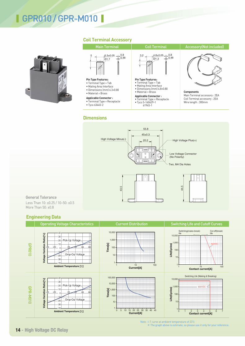
GPR010 / GPR-M010
Main Terminal Coil Terminal Accessory(Not included)
Pin Type Features:• Terminal Type = Tab• Mating Area Interface• Dimensions (mm) 6.3×0.80• Material = Brass
Applicable Connector :• Terminal Type = Receptacle• Tyco 63445-2
Pin Type Features:• Terminal Type = Tab• Mating Area Interface• Dimensions (mm) 4.8×0.80• Material = BrassApplicable Connector :• Terminal Type = Receptacle• Tyco 5-160429-1 61945-1
ComponentsMain Terminal accessory : 2EACoil Terminal accessory : 2EAWire length : 300mm
Operating Voltage Characteristics Current Distribution Switching Life and Cutoff Curves
General ToleranceLess Than 10: ±0.25 / 10~50: ±0.5More Than 50: ±0.8
Note : I-T curve at ambient temperature of 23℃ ※ The graph above is estimate, so please use it only for your reference.
5 6.3±0.05 0.80.48Ø1.7
3.2 4.8±0.05 0.80.48Ø1.3
43.5
44.5
High Voltage Minus(-) High Voltage Plus(+)
Low Voltage Connector(No Polarity)
Two, M4 Dia Holes
55.8
45±0.3
20.2
Volt
age
Vari
atio
n R
atio
[%]
Ambient Temperature [℃]
-40 -20 20 40 60 8010
20
30
40
0
-10
-20
-30
-40
Pick-Up Voltage
Drop-Out Voltage
Tim
e[s]
Current[A]
10,000
1,000
100
10
11 10 100
Contact current[A]
11
10
10 100
100
1,000
10,000
Life
(Cyc
les)
450VDC
Switching(make+break)life
Cut-off(break) life
Volt
age
Vari
atio
n R
atio
[%]
Ambient Temperature [℃]
-40 -20 20 40 60 8010
20
30
40
0
-10
-20
-30
-40
Pick-Up Voltage
Drop-Out Voltage
Tim
e[s]
Current[A]
100,000
10,000
1,000
100
10
120 25 30 35 40 4550 10 15
Contact current[A]
Life
(Cyc
les)
Switching Life (Making & Breaking)10,000
1,000
100
10
12 3 4 5 6 710
600VDC
Coil Terminal Accessory
Dimensions
Engineering DataGPR010
GPR-M010
LSIS - 15
LSIS - High Voltage DC Relay
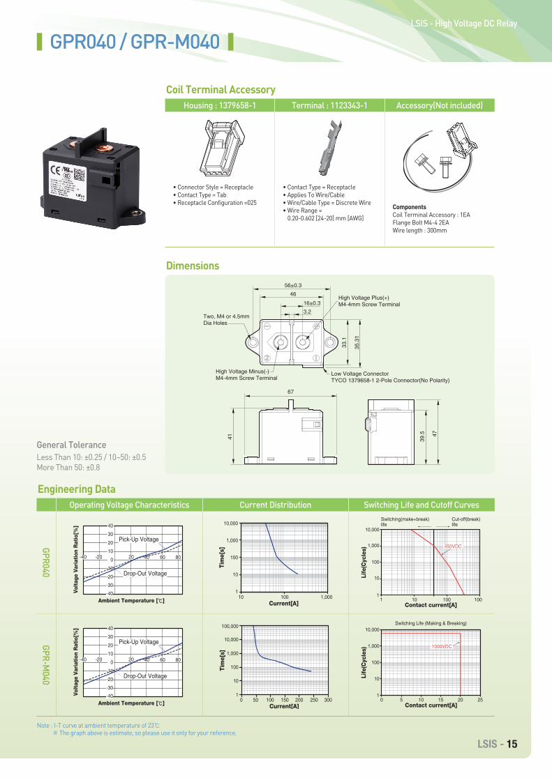
GPR040 / GPR-M040
Housing : 1379658-1 Terminal : 1123343-1 Accessory(Not included)
• Connector Style = Receptacle• Contact Type = Tab• Receptacle Configuration =025
• Contact Type = Receptacle• Applies To Wire/Cable• Wire/Cable Type = Discrete Wire• Wire Range =
0.20-0.602 [24-20] mm [AWG]
ComponentsCoil Terminal Accessory : 1EAFlange Bolt M4-4 2EAWire length : 300mm
Operating Voltage Characteristics Current Distribution Switching Life and Cutoff Curves
General ToleranceLess Than 10: ±0.25 / 10~50: ±0.5More Than 50: ±0.8
Note : I-T curve at ambient temperature of 23℃ ※ The graph above is estimate, so please use it only for your reference.
Coil Terminal Accessory
Dimensions
Engineering DataGPR040
GPR-M040
67
41 39.5 47
High Voltage Minus(-)M4-4mm Screw Terminal
Low Voltage ConnectorTYCO 1379658-1 2-Pole Connector(No Polarity)
High Voltage Plus(+)M4-4mm Screw Terminal
Two, M4 or 4.5mmDia Holes
33.1
35.3
1
56±0.3
46
3.2
16±0.3
-40 -20 20 40 60 8010
20
30
40
0
-10
-20
-30
-40
Pick-Up Voltage
Drop-Out Voltage
Volt
age
Vari
atio
n R
atio
[%]
Ambient Temperature [℃]
Tim
e[s]
Current[A]
10,000
1,000
100
10
110 100 1,000
450VDC
Contact current[A]
11
10
10 100 100
100
1,000
10,000
Life
(Cyc
les)
Switching(make+break)life
Cut-off(break) life
-40 -20 20 40 60 8010
20
30
40
0
-10
-20
-30
-40
Pick-Up Voltage
Drop-Out Voltage
Volt
age
Vari
atio
n R
atio
[%]
Ambient Temperature [℃]
Tim
e[s]
Current[A]
100,000
10,000
1,000
100
10
10 50 100 150 200 250 300
Contact current[A]
Life
(Cyc
les)
Switching Life (Making & Breaking)
1000VDC
0 5 10 15 20 25
10,000
1,000
100
10
1
16 - High Voltage DC Relay
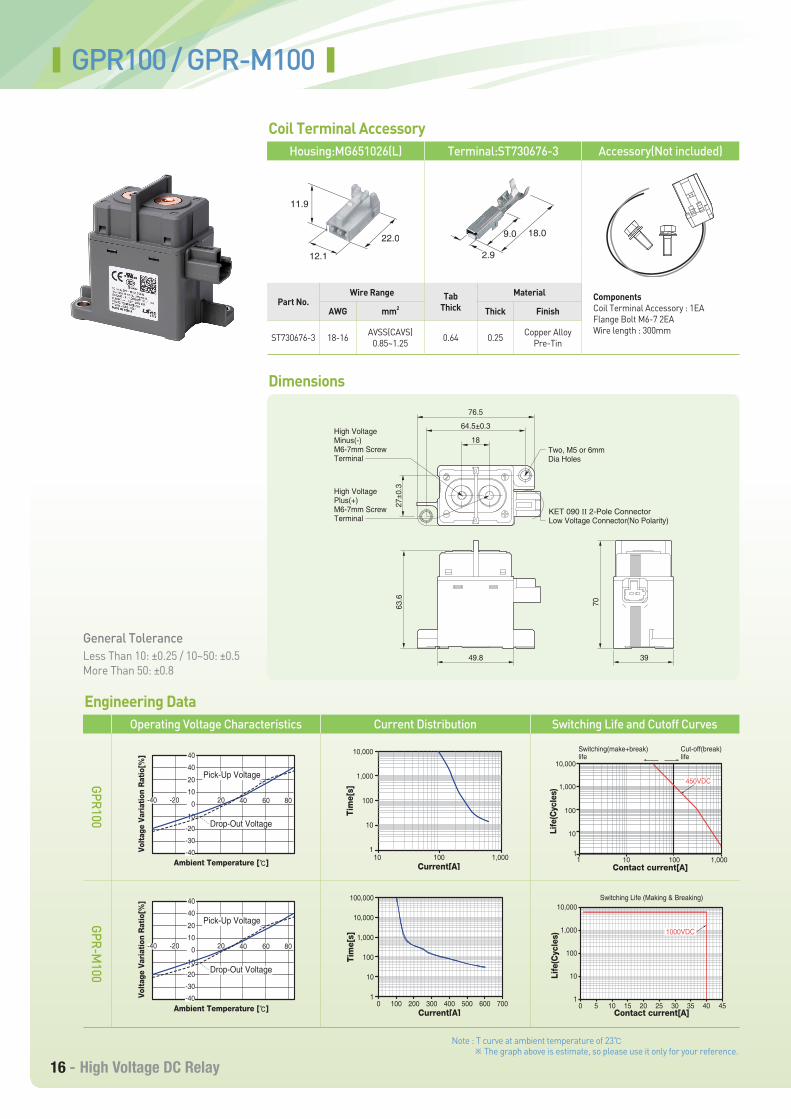
Part No.Wire Range
AWG mm2
ST730676-3 18-16 AVSS(CAVS)0.85~1.25
TabThick
Material
Thick Finish
0.64 0.25 Copper AlloyPre-Tin
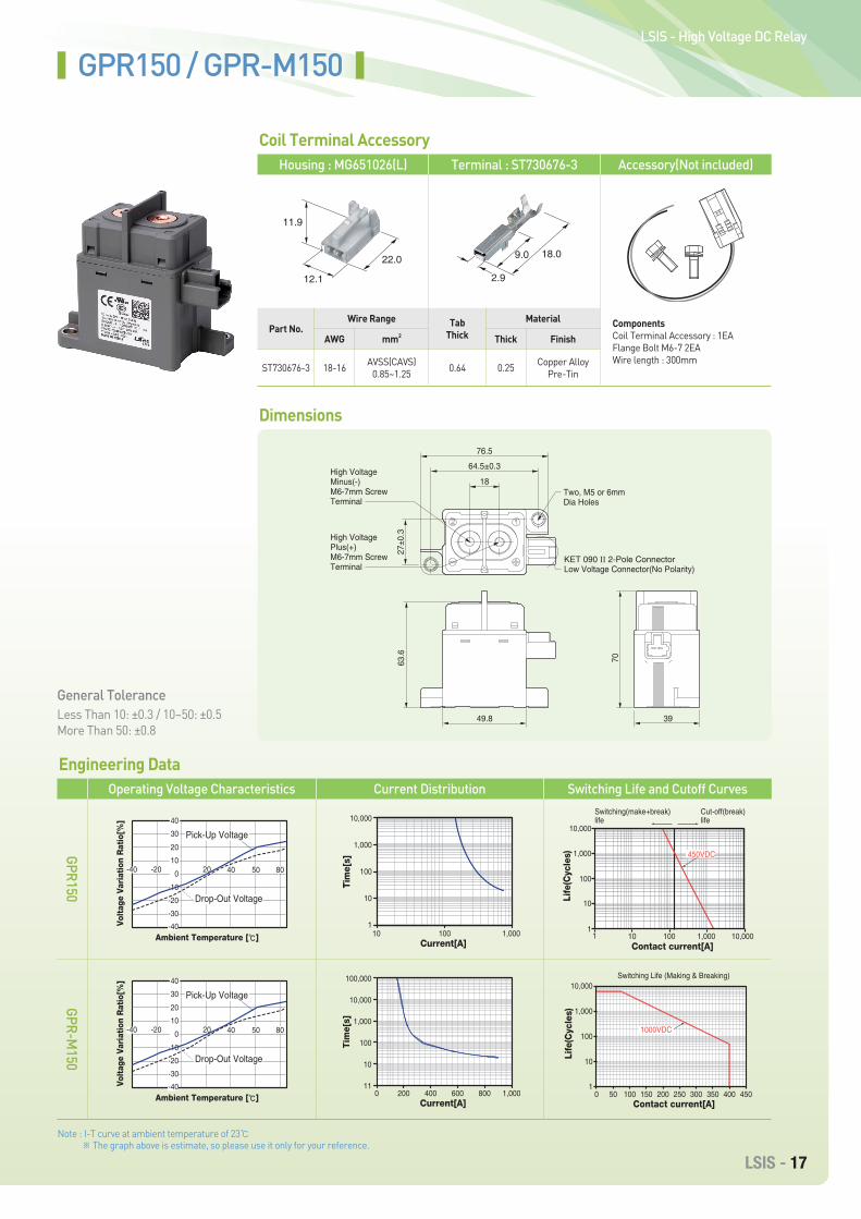
GPR100 / GPR-M100
Housing:MG651026(L) Terminal:ST730676-3 Accessory(Not included)
ComponentsCoil Terminal Accessory : 1EAFlange Bolt M6-7 2EAWire length : 300mm
Operating Voltage Characteristics Current Distribution Switching Life and Cutoff Curves
General ToleranceLess Than 10: ±0.25 / 10~50: ±0.5More Than 50: ±0.8
Note : T curve at ambient temperature of 23℃ ※ The graph above is estimate, so please use it only for your reference.
Coil Terminal Accessory
Dimensions
Engineering DataGPR100
GPR-M100
12.1
11.9
22.0
2.9
9.0 18.0
-40 -20 20 40 60 8010
20
40
40
0
-10
-20
-30
-40
Pick-Up Voltage
Drop-Out Voltage
Volt
age
Vari
atio
n R
atio
[%]
Ambient Temperature [℃]
Tim
e[s]
Current[A]
10,000
1,000
100
10
110 100 1,000
450VDC
Contact current[A]1
1
10
10 100 1,000
100
1,000
10,000
Life
(Cyc
les)
Switching(make+break)life
Cut-off(break) life
-40 -20 20 40 60 8010
20
40
40
0
-10
-20
-30
-40
Pick-Up Voltage
Drop-Out Voltage
Volt
age
Vari
atio
n R
atio
[%]
Ambient Temperature [℃]
Tim
e[s]
Current[A]
100,000
10,000
1,000
100
10
10 100 200 300 400 500 600 700
Contact current[A]
Life
(Cyc
les)
Switching Life (Making & Breaking)10,000
1,000
100
10
10 5 10 15 20 25 30 35 40 45
1000VDC
Two, M5 or 6mmDia Holes
76.5
18
49.8 39
64.5±0.3
27±0
.363
.6
70
KET 090 II 2-Pole ConnectorLow Voltage Connector(No Polarity)
High Voltage Minus(-)M6-7mm ScrewTerminal
High Voltage Plus(+)M6-7mm ScrewTerminal
LSIS - 17
LSIS - High Voltage DC Relay
Part No.Wire Range
AWG mm2
ST730676-3 18-16 AVSS(CAVS)0.85~1.25
TabThick
Material
Thick Finish
0.64 0.25 Copper AlloyPre-Tin
Housing : MG651026(L) Terminal : ST730676-3 Accessory(Not included)
ComponentsCoil Terminal Accessory : 1EAFlange Bolt M6-7 2EAWire length : 300mm
Coil Terminal Accessory
GPR150 / GPR-M150
Operating Voltage Characteristics Current Distribution Switching Life and Cutoff Curves
General ToleranceLess Than 10: ±0.3 / 10~50: ±0.5More Than 50: ±0.8
Note : I-T curve at ambient temperature of 23℃ ※ The graph above is estimate, so please use it only for your reference.
Dimensions
Engineering DataGPR150
GPR-M150
12.1
11.9
22.0
2.9
9.0 18.0
Two, M5 or 6mmDia Holes
76.5
18
49.8 39
64.5±0.3
27±0
.363
.6
70
KET 090 II 2-Pole ConnectorLow Voltage Connector(No Polarity)
High Voltage Minus(-)M6-7mm ScrewTerminal
High Voltage Plus(+)M6-7mm ScrewTerminal
Pick-Up Voltage
-40 -20 20 40 50 8010
20
30
40
0
-10
-20
-30
-40
Drop-Out Voltage
Volt
age
Vari
atio
n R
atio
[%]
Ambient Temperature [℃]
Tim
e[s]
Current[A]
10,000
1,000
100
10
110 100 1,000
Contact current[A]
11
10
10 100 1,000 10,000
100
1,000
10,000
Life
(Cyc
les) 450VDC
Switching(make+break)life
Cut-off(break) life
Pick-Up Voltage
-40 -20 20 40 50 8010
20
30
40
0
-10
-20
-30
-40
Drop-Out Voltage
Volt
age
Vari
atio
n R
atio
[%]
Ambient Temperature [℃]
Tim
e[s]
Current[A]
100,000
10,000
1,000
100
10
110 200 400 600 800 1,000
Contact current[A]
Life
(Cyc
les)
Switching Life (Making & Breaking)10,000
1,000
100
10
10 50 100 150 200 250 300 350 400 450
1000VDC
18 - High Voltage DC Relay
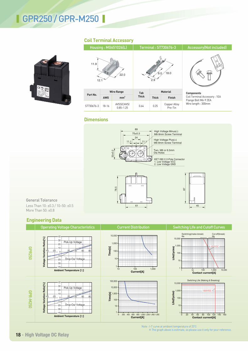
Part No.Wire Range
AWG mm2
ST730676-3 18-16 AVSS(CAVS)0.85~1.25
TabThick
Material
Thick Finish
0.64 0.25 Copper AlloyPre-Tin
Housing : MG651026(L) Terminal : ST730676-3 Accessory(Not included)
ComponentsCoil Terminal Accessory : 1EAFlange Bolt M6-9 2EAWire length : 300mm
Coil Terminal Accessory
GPR250 / GPR-M250
Operating Voltage Characteristics Current Distribution Switching Life and Cutoff Curves
General ToleranceLess Than 10: ±0.3 / 10~50: ±0.5More Than 50: ±0.8
Note : I-T curve at ambient temperature of 23℃ ※ The graph above is estimate, so please use it only for your reference.
Dimensions
Engineering DataGPR250
GPR-M250
12.1
11.9
22.0
2.9
9.0 18.0
11.1 11.1
61
87
45
Two, M6 or 6.5mmDia Holes
32±0
.278
.5
75±0.3
89
24High Voltage Plus(+)M6-9mm Screw Terminal
High Voltage Minus(-)M6-9mm Screw Terminal
KET 090 II 2-Pole Connector1. Low Voltage VCC2. Low Voltage GND
Pick-Up Voltage
-40 -20 20 40 60 8010
20
30
40
0
-10
-20
-30
-40
Drop-Out Voltage
Volt
age
Vari
atio
n R
atio
[%]
Ambient Temperature [℃] 10 1,000100
Tim
e[s]
Current[A]
10,000
1,000
100
10
110,0001,0001001 10
450VDC
Contact current[A]
1
10
100
1,000
10,000
Life
(Cyc
les)
Switching(make+break)life
Cut-off(break) life
Pick-Up Voltage
-40 -20 20 40 60 8010
20
30
40
0
-10
-20
-30
-40
Drop-Out Voltage
Volt
age
Vari
atio
n R
atio
[%]
Ambient Temperature [℃]
Tim
e[s]
Current[A]
0 200 400 600 800 1,000 1,200 1,400 1,600
100,000
10,000
1,000
100
10
1
Contact current[A]
Life
(Cyc
les)
Switching Life (Making & Breaking)10,000
1,000
100
10
10
1000VDC
20 40 60 80 100 120 140 160
LSIS - 19
LSIS - High Voltage DC Relay
Part No.Wire Range
AWG mm2
ST730676-3 18-16 AVSS(CAVS)0.85~1.25
TabThick
Material
Thick Finish
0.64 0.25 Copper AlloyPre-Tin
Housing : MG651026(L) Terminal : ST730676-3 Accessory(Not included)
ComponentsCoil Terminal Accessory : 1EAFlange Bolt M6-9 2EAWire length : 300mm
Coil Terminal Accessory
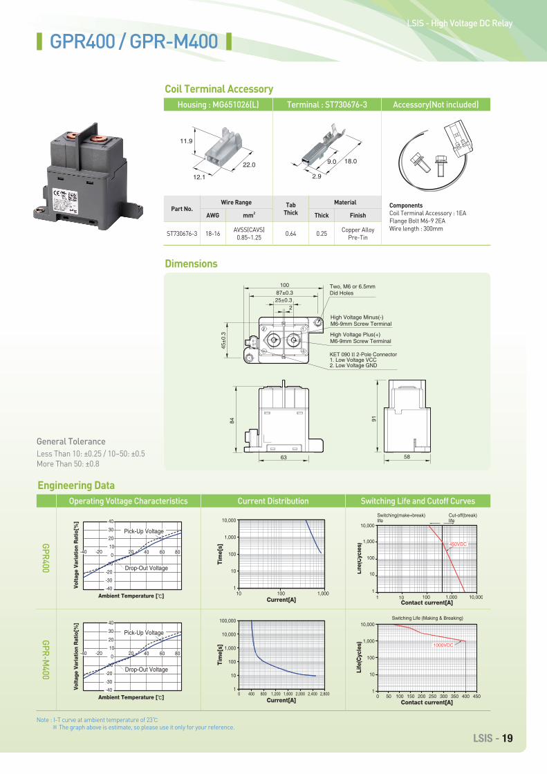
GPR400 / GPR-M400
Operating Voltage Characteristics Current Distribution Switching Life and Cutoff Curves
General ToleranceLess Than 10: ±0.25 / 10~50: ±0.5More Than 50: ±0.8
Note : I-T curve at ambient temperature of 23℃ ※ The graph above is estimate, so please use it only for your reference.
Dimensions
Engineering DataGPR400
GPR-M400
12.1
11.9
22.0
2.9
9.0 18.0
100
84
63 58
91
87±0.325±0.3
45±0
.3
2
High Voltage Minus(-)M6-9mm Screw Terminal
High Voltage Plus(+)M6-9mm Screw Terminal
Two, M6 or 6.5mmDid Holes
KET 090 II 2-Pole Connector1. Low Voltage VCC2. Low Voltage GND
-40 -20 20 40 60 8010
20
30
40
0
-10
-20
-30
-40
Pick-Up Voltage
Drop-Out Voltage
Volt
age
Vari
atio
n R
atio
[%]
Ambient Temperature [℃] 10 1,000100
Tim
e[s]
Current[A]
10,000
1,000
100
10
1
10,0001,0001001 10
450VDC
Contact current[A]
1
10
100
1,000
10,000
Life
(Cyc
les)
Switching(make+break)life
Cut-off(break) life
-40 -20 20 40 60 8010
20
30
40
0
-10
-20
-30
-40
Pick-Up Voltage
Drop-Out Voltage
Volt
age
Vari
atio
n R
atio
[%]
Ambient Temperature [℃]
Tim
e[s]
Current[A]0 400 800 1,200 1,600 2,000 2,400 2,800
100,000
10,000
1,000
100
10
1
Contact current[A]
Life
(Cyc
les)
0 50 100 150 200 250 300 350 400 450
10,000
1,000
100
10
1
Switching Life (Making & Breaking)
1000VDC
20 - High Voltage DC Relay
Part No.Wire Range
AWG mm2
ST730676-3 18-16 AVSS(CAVS)0.85~1.25
TabThick
Material
Thick Finish
0.64 0.25 Copper AlloyPre-Tin
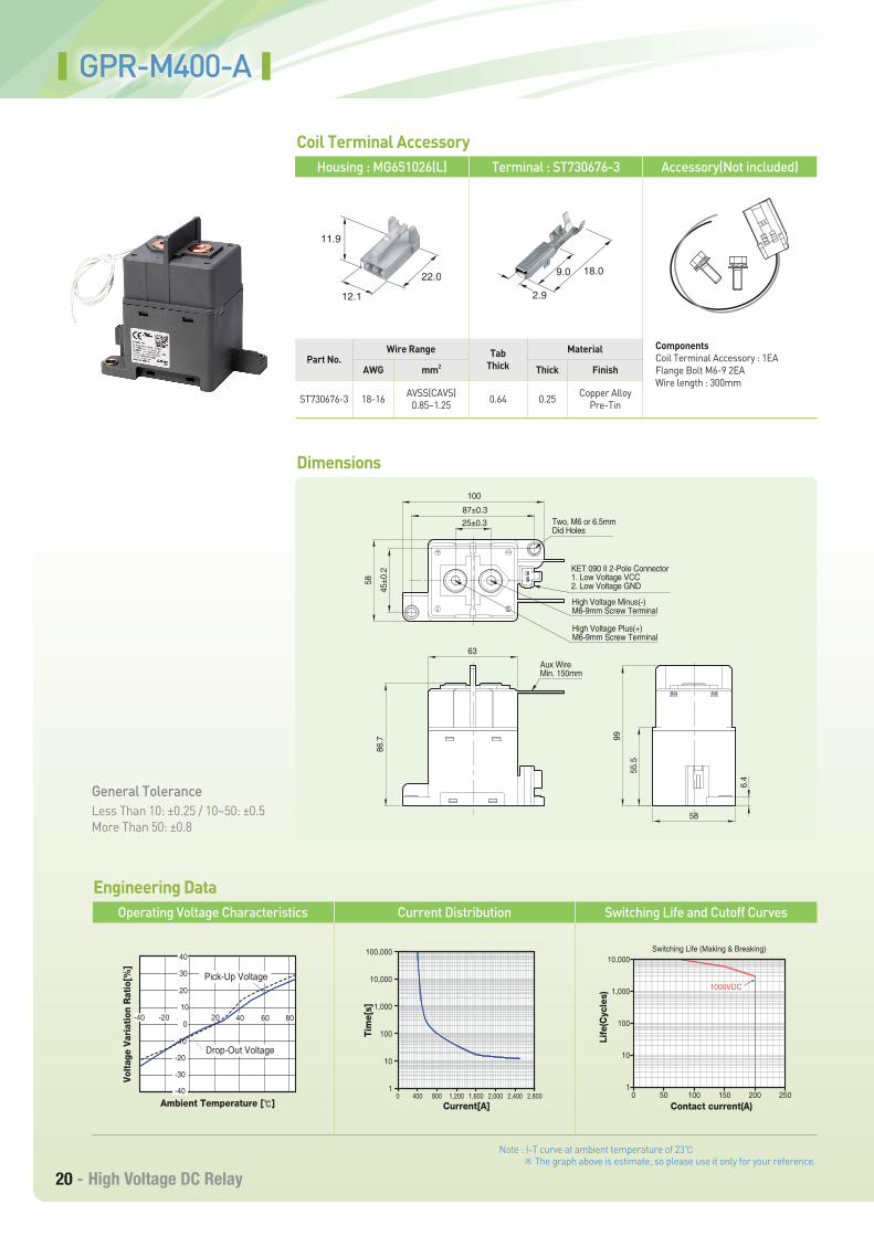
Housing : MG651026(L) Terminal : ST730676-3 Accessory(Not included)
ComponentsCoil Terminal Accessory : 1EAFlange Bolt M6-9 2EAWire length : 300mm
Coil Terminal Accessory
GPR-M400-A
Operating Voltage Characteristics Current Distribution Switching Life and Cutoff Curves
General ToleranceLess Than 10: ±0.25 / 10~50: ±0.5More Than 50: ±0.8
Note : I-T curve at ambient temperature of 23℃ ※ The graph above is estimate, so please use it only for your reference.
Dimensions
Engineering Data
12.1
11.9
22.0
2.9
9.0 18.0
-40 -20 20 40 60 8010
20
30
40
0
-10
-20
-30
-40
Volt
age
Vari
atio
n R
atio
[%]
Ambient Temperature [℃]
Pick-Up Voltage
Drop-Out Voltage
86.7
58
45±0
.2
99
6.4
55.5
58
25±0.387±0.3
100
Two, M6 or 6.5mmDid Holes
High Voltage Minus(-)M6-9mm Screw Terminal
High Voltage Plus(+)M6-9mm Screw Terminal
Aux WireMin. 150mm
KET 090 II 2-Pole Connector1. Low Voltage VCC2. Low Voltage GND
12
63
Tim
e[s]
Current[A]
100,000
10,000
1,000
100
10
10 400 800 1,200 1,600 2,000 2,400 2,800
Contact current(A)
Life
(Cyc
les)
0
10,000
50 100 150 200 250
1,000
100
10
1
Switching Life (Making & Breaking)
1000VDC
LSIS - 21
LSIS - High Voltage DC Relay
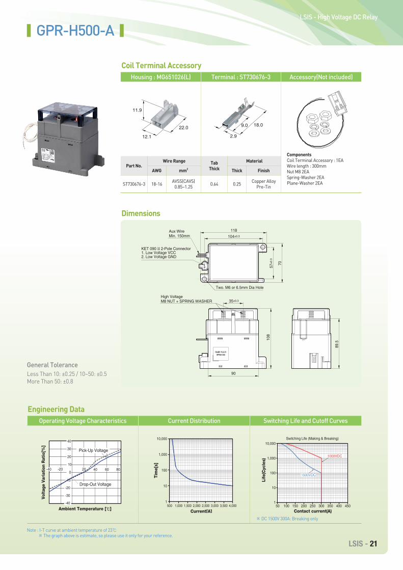
Part No.Wire Range
AWG mm2
ST730676-3 18-16 AVSS(CAVS)0.85~1.25
TabThick
Material
Thick Finish
0.64 0.25 Copper AlloyPre-Tin
Housing : MG651026(L) Terminal : ST730676-3 Accessory(Not included)
ComponentsCoil Terminal Accessory : 1EAWire length : 300mmNut M8 2EASpring-Washer 2EAPlane-Washer 2EA
Coil Terminal Accessory
GPR-H500-A
Operating Voltage Characteristics Current Distribution Switching Life and Cutoff Curves
General ToleranceLess Than 10: ±0.25 / 10~50: ±0.5More Than 50: ±0.8
Note : I-T curve at ambient temperature of 23℃ ※ The graph above is estimate, so please use it only for your reference.
※ DC 1500V 300A: Breaking only
Dimensions
Engineering Data
12.1
11.9
22.0
2.9
9.0 18.0
-40 -20 20 40 60 8010
20
30
40
0
-10
-20
-30
-40
Volt
age
Vari
atio
n R
atio
[%]
Ambient Temperature [℃]
Pick-Up Voltage
Drop-Out Voltage
90
35±0.3
104±0.3
57±0
.3
70
118
89.5
108
Two. M6 or 6.5mm Dia Hole
Aux Wire Min. 150mm
KET 090 II 2-Pole Connector1. Low Voltage VCC2. Low Voltage GND
High VoltageM8 NUT + SPRING WASHER
Tim
e[s]
Current[A]500
10,000
1,000
100
10
11,000 1,500 2,000 2,500 3,000 3,500 4,000
Contact current(A)
Life
(Cyc
les)
50
10,000
100 150 200 250 300 350 400 450
1,000
100
10
1
Switching Life (Making & Breaking)
1000VDC
1500VDC
22 - High Voltage DC Relay
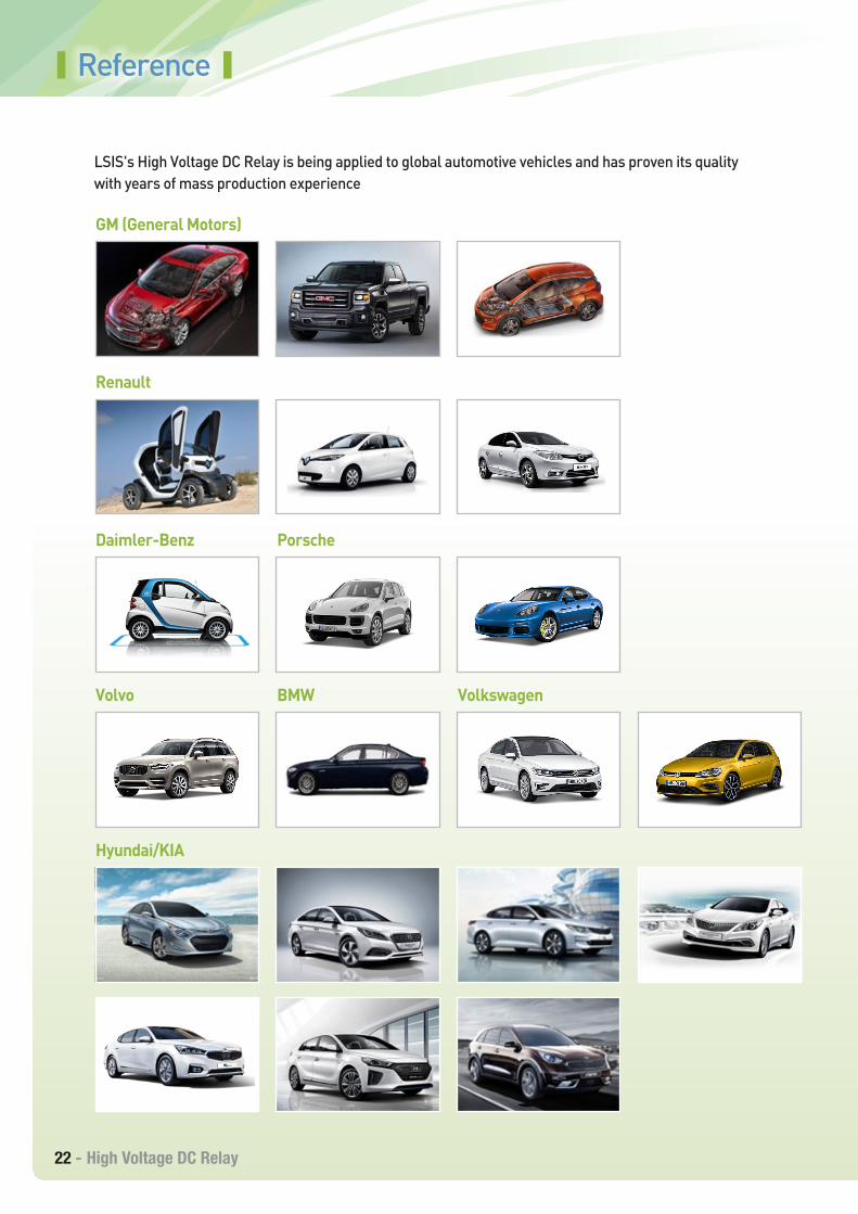
Hyundai/KIA
Volvo
Daimler-Benz
Renault
GM (General Motors)
BMW
Porsche
Volkswagen
Reference
LSIS's High Voltage DC Relay is being applied to global automotive vehicles and has proven its quality with years of mass production experience
LSIS - 23
LSIS - High Voltage DC Relay
Memo
2018. 07 ⓒ2017. 2 LSIS Co.,Ltd. All rights reserved. / English (04) 2018. 07 Staffcom
www.lsis.com
Specifications in this catalog are subject to change without notice due to continuous product development and improvement.
Overseas Branches• LSIS Shanghai Office (China)
Tel: 86-21-5237-9977 Fax: 86-21-5237-7189
• LSIS Beijing Office (China)Tel: 86-10-5761-3127 Fax: 86-10-5761-3128 E-Mail: [email protected]
• LSIS Guangzhou Offce (China) Tel: 86-20-8326-6784 Fax: 80-20-8326-6287 E-Mail: [email protected]
• LSIS Qingdao Office (China)Tel: 86-532-8501-6058 Fax: 86-532-8501-6057 E-Mail: [email protected]
• LSIS Chengdu Office (China)Tel: 86-28-8670-3200 Fax: 86-28-8670-3203 E-Mail: [email protected]
• LSIS ShenYang Office (China)Tel: 86-24-2321-9050 Fax: 86-24-8386-7210 E-Mail: [email protected]
• LSIS Jinan Office (China)Tel: 86-531-8699-7826 Fax: 86-531-8697-7628 E-Mail: [email protected]
• LSIS Co., Ltd. Tokyo Office (Japan)Tel: 81-3-6268-8241 Fax: 81-3-6268-8240 E-Mail: [email protected]
• LSIS Co., Ltd. Rep. Office (Vietnam)Tel: 84-8-3823-7890 E-Mail: [email protected]
• LSIS Moscow Office (Russia)Tel: 7-499-682-6130 E-Mail: [email protected]
• LSIS Jakarta Office (Indonesia)Tel: 62-21-293-7614 E-Mail: [email protected]
• LSIS Bangkok Office (Thailand)Tel: 66-2-053-9133 E-Mail: [email protected]
Head Quarter127 LS-ro (Hogye-dong) Dongan-gu, Anyang-si,Gyeonggi-Do, 14119, KoreaTel. 82-2-2034-4848, 4671, 4429 Fax: 82-2-2034-4555
Overseas Subsidiaries• LSIS(Dalian) Co., Ltd. (Dalian, China)
Tel: 86-411-8730-7510 Fax: 86-411-8730-7560 E-Mail: [email protected]
• LSIS(Wuxi) Co., Ltd. (Wuxi, China) Tel: 86-510-8534-6666-8005 Fax: 86-510-8534-4078 E-Mail: [email protected]
• LS VINA Industrial Systems Co., Ltd (Hanoi, Vietnam)Tel: 84-4-6275-8055 Fax: 84-4-3882-0220 E-Mail: [email protected]
• LSIS Middle East FZE (Dubai, U.A.E.)Tel: 971-4-886-5360 Fax: 971-4-886-5361 E-Mail: [email protected]
• LSIS Europe B.V. (Amsterdam, Netherlands)Tel: 31-20-654-1420 Fax: 31-20-654-1429 E-Mail: [email protected]
• LSIS Japan Co., Ltd. (Tokyo, Japan)Tel: 81-3-6268-8241 Fax: 81-3-6268-8240 E-Mail: [email protected]
• LSIS USA Inc. (Chicago, U.S.A)Tel: 1-800-891-2941 Fax: 1-847-383-6543 E-Mail: [email protected]