high voltage engineering e. gaxiola many thanks to high
TRANSCRIPT

CAS on Small Accelerators
High Voltage EngineeringEnrique Gaxiola
Many thanks to the Electrical Power Systems Group, Eindhoven University of Technology, The Netherlands& CERN AB-BT Group colleagues
Introductory examples
Theoretical foundation and numerical field simulation methods
Generation of high voltages
Insulation and Breakdown
Measurement techniques

CAS on Small Accelerators
Introduction E.Gaxiola:Studied Power EngineeringPh.D. on Dielectric Breakdown in Insulating Gases;
Non-Uniform Fields and Space Charge EffectsIndustry R&D on Plasma Physics / Gas DischargesCERN Accelerators & Beam, Beam Transfer,Kicker Innovations:• Electromagnetism• Beam impedance reduction• Vacuum high voltage breakdown in traveling wave
structures.• Pulsed power semiconductor applications
CAS on Small Accelerators
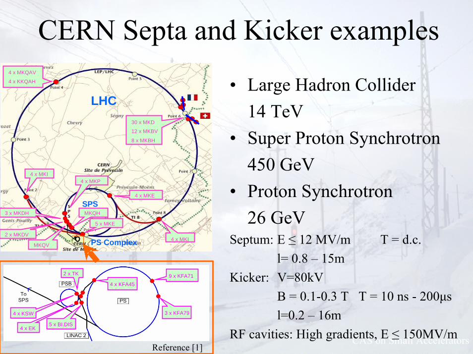
CERN Septa and Kicker examples
• Large Hadron Collider14 TeV
• Super Proton Synchrotron450 GeV
• Proton Synchrotron26 GeV
Septum: E ≤ 12 MV/m T = d.c.l= 0.8 – 15m
Kicker: V=80kVB = 0.1-0.3 T T = 10 ns - 200μsl=0.2 – 16m
RF cavities: High gradients, E ≤ 150MV/m
PS
LHC
SPS
PS ComplexPS
LHC
SPS
PS Complex
4 x MKQAV
4 x KKQAH
4 x MKI
30 x MKD
12 x MKBV
8 x MKBH
4 x MKI
4 x MKE
4 x MKP
MKQH
2 x MKDV
3 x MKDH
MKQV
5 x MKE
9 x KFA71
3 x KFA79
4 x KFA45
4 x KSW
4 x EK5 x BI.DIS
2 x TK
PS
LHC
SPS
PS ComplexPS
LHC
SPS
PS Complex
4 x MKQAV
4 x KKQAH
4 x MKI
30 x MKD
12 x MKBV
8 x MKBH
4 x MKI
4 x MKE
4 x MKP
MKQH
2 x MKDV
3 x MKDH
MKQV
5 x MKE
9 x KFA71
3 x KFA79
4 x KFA45
4 x KSW
4 x EK5 x BI.DIS
2 x TK 9 x KFA71
3 x KFA79
4 x KFA45
4 x KSW
4 x EK5 x BI.DIS
2 x TK
Reference [1]

CAS on Small Accelerators
PS septa SEH23
Voltage: 300 kV
SPS septa ZS

CAS on Small Accelerators
• SPS injection kicker magnets
30 kV
spacers
beam gap
magnets
ferrites

CAS on Small Accelerators
Courtesy: E2V Technologies
Magnets
• SPS extraction kickers
60 kV
72 kV30 kV
Power Semiconductor Diode stackThyratron gas discharge switches
GeneratorsPulse Forming Network

CAS on Small Accelerators
• Maxwell equations for calculatingElectromagnetic fields, voltages, currents– Analytical– Numerical

CAS on Small Accelerators
Breakdown
ElectricalFields,
GeometryMedium
Insulation andBreakdown
High fieldsField enhancement Field steering
Charges in fieldsIonisationBreakdown
GasLiquidsSolidsVacuum

CAS on Small Accelerators
-CSM (Charge Simulation Method): (Coulomb)
Electrode configuration is replaced by a set of discrete charges
- FDM (Finite Difference Method):
Laplace equation is discretised on a rectangular grid
- FEM (Finite Element Method): Vector Fields (Opera, Tosca), Ansys, Ansoft
Potential distribution corresponds with minimum electric field energy (w=½εE2)
- BEM (Boundary Element Method): IES (Electro, Oersted)
Potential and its derivative in normal direction on boundary are sufficient
NUMERICAL FIELD SIMULATION METHODS

CAS on Small Accelerators
Procedure FEM1. Generate mesh of triangles:
2. Calculate matrix coefficients:
3. Solve matrix equation:
4. Determine equipotential lines and/or field lines
[ ] ( )AS jiij αα ∇⋅∇=
[ ] 0=⎥⎦
⎤⎢⎣
⎡
p
fkpkf U
USS
Procedure BEM1. Generate elements along interfaces
2. Generate matrix coefficients:
3. Solve matrix equation:
4. Determine potential on abritary position:
∫∫ =∂
∂=
jj Siij
S
iij dsrGds
nrH ln,ln
( ) ∑∑==
=−n
jjij
n
jjijij QGUH
11
πδ
⎟⎟⎠
⎞⎜⎜⎝
⎛−
∂∂
= ∑ ∫∑ ∫==
n
j Sj
n
j Sj
jj
rdsQdsn
rUyxU11
00 lnln21),(π

CAS on Small Accelerators
Generation of High Voltages• AC Sources (50/60 Hz)
High voltage transformer (one coil; divided coils; cascade)Resonance source (series; parallel)
• DC SourcesRectifier circuits (single stage; cascade)Electrostatic generator (van de Graaff generator)
• Pulse sourcesPulse circuits (single stage; cascade; pulse transformer)Traveling wave generators (PFL; PFN; transmission line transformer)

CAS on Small Accelerators
Cascaded High voltage transformer
1: primary coil2: secondary coil3: tertiary coil
900 kV400 ACourtesy: Delft Univ.of Techn.

CAS on Small Accelerators
L R
C
Equivalent Circuit:
C
L
L
L
cap.deler
testν
Resonance Source
+ Waveform: almost perfect sinusoidal
+ Power: 1/Q of “normal” transformer
+ Short circuit: Q→0 results in V→0
- No resistive load2
002
0
)(1)(
ωωωωωωω−+
=Q
QH
CL
RQ
LC1and1
0 ==ω
900 kV100 mA
Courtesy: Eindhoven Univ.of Techn.

CAS on Small Accelerators
Cascaded Rectifier(Greinacher; Cockcroft - Walton)
max2nVVDC =Cn
Cn`
Dn
Dn`
C1
C1`
D1
D1`
C2
C2`
D2
D2`
Cn-1
Cn-1`
Dn-1
Dn-1`
stage 1
stage n
stage n-1
stage 2
nn`
22`
11`
amplitude: Vmax
VDC
Reduce δV (~n2) and ΔV (~n3) by:larger C’s (more energy in cascade)higher f (up to tens of kilohertz)
Voltage: 2 MV
Courtesy: Delft Univ.of Techn.

CAS on Small Accelerators
G
C2
R1
C1 R2
U(t)V0
Single-Stage Pulse Source
( )12 //0)( ττ tt eeVtU −− −=
if C1 >> C2 and R2 >> R1rise time: τ1=R1C2discharge time: τ2=R2C1
spark gaps
02
2
=++ bUdt
dUadt
Ud
2211212211
1;111CRCR
bCRCRCR
a =++=
t
U
“LC”-oscillations
τ1 (front)τ2 (discharge)
Standard lightning surge pulse: 1.2 / 50 μs
60 kV1 kA
Courtesy: Eindhoven Univ.of Techn.

CAS on Small Accelerators
Cascade Pulse Source(Marx Generator)
DCpulse VnV ⋅=
C``
R2`
R`
C1`
R2`
R2`
R2`
C1`
C1`
C1`
R`
R`
R`
stage 1
stage 2
stage 3
stage n
VDC
G1
G2
G3
Gn
B1
A1
B2
A2
B3
A3
Bn
An
C`
Vpulse
Total discharge capacity: 1/C1=∑1/C1’Front resistance: R1=R1”+∑R1’Discharge resistance: R2=∑R2’
R1: front resistor
R2: discharge resistor
R1`
R2`
R`
R1``
C1`
R1`
R1`
R1`
R2`
R2`
R2`
C1`
C1`
C1`
R`
R`
R`
VDC
900 kV100 mA
Courtesy: Kema, The Netherlands

CAS on Small Accelerators
GC2
R1
C1R2
U2
U1
resistivity neglected
I1
I2
dtdtU 1
1 )( Φ=
dtdtU 2
2 )( Φ=
Pulse Source with Transformer
0:secondary
0:primary
221
2
222
2
22
122
2
121
2
11
=+−
=+−
Idt
IdMCdt
IdCL
Idt
IdMCdt
IdCL
011121
2222211
2
12
2
1
222
111 =−⎟⎠⎞
⎜⎝⎛ −⎟⎠⎞
⎜⎝⎛ −⇒⎟⎟
⎠
⎞⎜⎜⎝
⎛=⎟⎟
⎠
⎞⎜⎜⎝
⎛⎟⎟⎠
⎞⎜⎜⎝
⎛−
−CCMCLCL
ii
ii
CLMCMCCL
ωωω
)//(111
11,
)(11
'212211
22'2112211
1CCLCLCLkCCLCLCL eq
=+−
≈+
=+
≈ ωω
slow oscillation fast oscillation
Eigen frequencies from characteristic equation:
Approximation: transformer almost ideal: k=M/√(L1L2)→1
Voltage: 300 kV

CAS on Small Accelerators
charge cable load cableS
R
VDC
Z
Pulse Forming Line / Network
Transmission Line Transformer
S
ZVDC cables
parallel cables in series
amplitude: ½VDC
duration: 2L/v
Courtesy: Eindhoven Univ.of Techn.150 kV1 kA
80 kV, 10 kA, T=20ns - 10μs

CAS on Small Accelerators
Insulation and Breakdown• In Gases Ionisation and Avalanche Formation
Townsend and Streamer BreakdownPaschen Law: Gas TypeBreakdown Along InsulatorInhomogeneous Fields, Pulsed Voltages, Corona
• Insulating Liquids
• Solid InsulationBreakdown types, Surface tracking, Partial discharges, Polarisation, tan δ
• Vacuum InsulationApplications, Breakdown, Cathode Triple-Point, Insulator Surface Charging, Conditioning

CAS on Small Accelerators800kV South Africa
400kV400kV Geertruidenberg,The Netherlands

CAS on Small Accelerators
Townsend’s 1st ionisation coefficient αOne electron creates α new electrons per unit length
A + e → A+ + 2e
ne(x=d) = n0eαd
α/p = f (E/P)
1st free electron• Cosmic radiation• Shortwave UV• Radio active isotopes
Free path, effective cross-section
In air:≈ 2.5 x 10¹⁹ molecules/cm3
≈ 1000 ions/cm3
≈ 10 electrons/cm3

E
1st
electron
New 1st
electronSecondary γ
Photon or ion
Avalanche-----+
+
+
++
• Electro-negative gassesAttachment η of electrons to ions
electrons: ne(x=d) = n0e(α -η)d
negative ions:]1[n)( )(o
−−
== −−
dedxn ηα
ηαη
α-η vs. E/p1.) air2.) SF6
Reference [3]Townsend’s 2nd ionisation coefficient γone ion or photon creates γ new electronsat cathode ne = γn0(eαd-1)
Breakdown if: # secondary electrons ≥ n0αd ≥ ln(1/γ + 1)
steep function of E/p eαd very steep (E/p)critical and Vdwell defined γ of weak influence
Avalanche ≠ Breakdown;creation of secondaries

CAS on Small Accelerators
Paschen law / breakdown field
1: SF62: air3: H24: Ne
• Townsend breakdown criterion αd = K:with A=σI/kT
B=ViσI/kT
Ed and Vd depend only on p*d p: pressure d: gap length
ln(Apd/K)B
pEd =
ln(Apd/K)BpdVd =
Typically practicallyEbd= 10 kV/cmat 1 bar in air
Reference [2] Vbd,Paschen min, air ≈ 300 V
• Small p*d, d<< λ: few collisions, high field required for ionisation• Large p*d, d>> λ: collision dominated, small energy build-up, high Vd
CAS on Small Accelerators
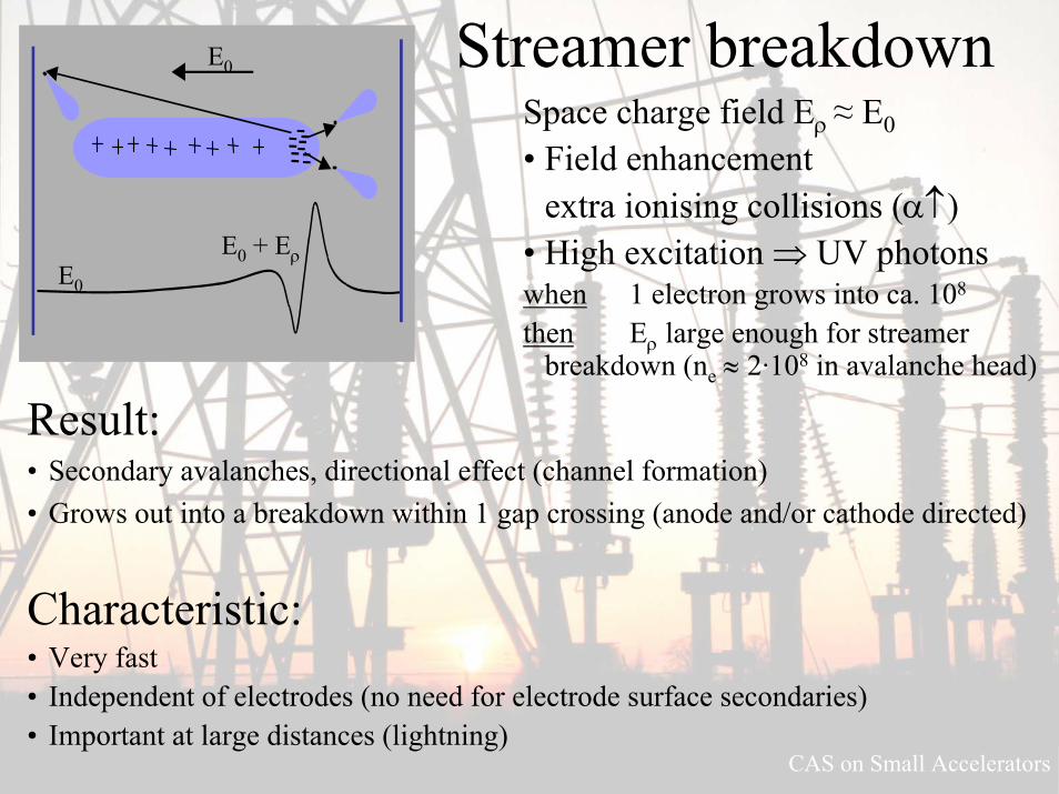
Streamer breakdownE0
E0
E0 + Eρ
Space charge field Eρ≈ E0• Field enhancement
extra ionising collisions (α↑)• High excitation ⇒ UV photonswhen 1 electron grows into ca. 108
then Eρ large enough for streamer breakdown (ne ≈ 2·108 in avalanche head)
Result:• Secondary avalanches, directional effect (channel formation)• Grows out into a breakdown within 1 gap crossing (anode and/or cathode directed)
Characteristic:• Very fast • Independent of electrodes (no need for electrode surface secondaries)• Important at large distances (lightning)

CAS on Small Accelerators
Townsend, unless:
• Strong non-uniform field(small electrodes, few secondary electrons)
• Pulsed voltages– Townsend slow, ion drift, subsequent gap transitions– Streamer fast, photons, 1 gap transition
• High pressure– Less diffusion
Eρ high– photons absorbed
in front of cathode– positive ions
slower
• Townsend: αd ≥ ln(1/γ + 1) ≈ 7...9(γ ≈ 10-4...10-3)
• Streamer: αd ≥ 18...20
Laser-induced streamer breakdown in air.
Courtesy: Eindhoven Univ.of Techn.

CAS on Small Accelerators
Breakdown along insulator • Surface charge• (Non-regular) surface conduction• Particles / contaminations on surface• Non-regularities (scratches, ridges)
⇒Field enhancement⇒ Increased breakdown probability
Prebreakdown along insulatior in air.Courtesy: Eindhoven Univ.of Techn.
Reference [2]

CAS on Small Accelerators
Breakdown at pulse voltages;time-lag
ts, wait for first elektrontf, breakdown formation• Townsend or Streamer
Short pulses, high breakdown voltage
Reference [2]

CAS on Small Accelerators
Non-uniform fields; Corona
Breakdown conditions:• Global Full breakdown• Local Streamer breakdown
Partial discharge
Non-uniform field:• Discharge starts in high field
region• ....and “extinguishes” in low
field region
Reference [2]

CAS on Small Accelerators
Corona- Power loss; EM noise- Chemical corrosion+ Useful applications
10 ns
20 ns
30 ns
40 ns
Transmission line transformerCourtesy: Eindhoven Univ.of Techn.
Pulsed corona discharges:• Fast, short duration HV pulses• Many streamers, high density• Generation of electrons, radicals,
excited molecules, UV• E.g. Flue gas cleaning

Solid insulationBreakdown field strength:• Very clean (lab): high• Practical: lower due to imperfections
– Voids– Absorbed water– Contaminations– Structural deformations
Requirements:• Mechanical strength• Contact with electrodes and
semiconducting layers• Resistant to high T, UV, dirt,
contamination, rain, ice, desert sand
Problems:• Surface tracking• Partial discharges
– In voids(in material or at electrodes, often created at production).
AnorganicNatural
Synthetic
Quartz,mica,glasPorcelain
Al2O
3
Disc insulatorFeedthrough
Spacer
Paper + OilCable
Capacitor
SyntheticOrganic
Polymerisation
PolyetheleneHD,LD,XL – PE
TeflonPolystyrene, PVC,
polypropene,etc
Spec. properties:
Moisture contenthigh T
lossesbonding
EpoxyHardener
FillerMoulding in mold
Types of solidinsulation materials

CAS on Small Accelerators
Surface trackingRemedies:• Geometry• Creeping distance (IEC-norm)• Surface treatment (emaillate, coating)• Washing

Vacuum insulation
Applications:• Vacuum circuit breaker• Cathode Ray Tubes / accelerators• Elektron microscope• X-ray tube• Transceiver tube
What is vacuum?• “Pressure at which no collisions
for Brownian “temperature”movements of electrons”
• λ >> characteristic distances• E.g. p = 10-6 bar, λ = 400 m
Advantages:• “Self healing”• No dielectric losses• High breakdown fieldstrength• Non flammable• Non toxic, non contaminating
Disadvantages:• Requires hermetic containment
and mechanical support• Quality determind by:
– electrodes and insulators– Material choice, machining– Contaminations, conditioning

CAS on Small Accelerators
Characteristics of vacuum breakdownNo 1st electron from “gas”• Cathode emission
– primary: photoemission, thermic emission, field emission, Schottky-emission
– secondary: e.g. e- bombarded anode → +ion collides at cathode → e-
No breakdown medium• No multiplication through collision ionisation• Medium in which the breakdown occurs has to be created
(“evaporated” from electrodes, insulators)
Important: prevent field emission• Keep field at cathode and “cathode triple point” as low as
possible• Insulator surface charging, conditioning

CAS on Small Accelerators
14
01
ConditioningInsulator surfacecharging
Breakdown vs.field cathode-triple-point
# Conditioning breakdowns neededto reach 50kV hold voltage
Courtesy: ESTEC / ESA
Ref [12]
Conditioningeffect lostwhen chargecompensated

Insulating liquids
• Transformers• Cables• Capacitors• Bushings
Requirements:• Pure, dry and free of gases• εr (high for C’s, low for trafo)
(demi water εr,d.c. = 80)• Stable (T), non-flammable,
non toxic (pcb’s), ageing, viscosity
Courtesy: Sandia labs, U.S.A.
• No interface problems
• Combined cooling/insulation
• “Cheap” (no mould)• Liquid tight housing
Applications:

CAS on Small Accelerators
Breakdown fieldstrength:• Very clean (lab): high 1 - 4 MV/cm (In practice much lower)• Important at production:outgassing, filtering, drying• Mineral oil (“old” time application, cheap, flammable)• Synthetic oil (purer, specifically made, more expensive)
– Silicon oil (very stable up to high T, non-toxic, expensive)• Liquid H2, N2, Ar, He (supra-conductors)• Demi-water (incidental applications, pulsed power)• Limitation Vbd:
– Inclusions: Partial discharges Oil decomposition → Breakdown– Growth (pressure increase) – “extension” in field direction”
• Particles drift to region with highest E → bridge formation → breakdown
+
-
+
-
+
-

Transformer:• Mineral oil: Insulation and cooling
• Paper: Barrier for charge carriers and chain formation– Mechanical strength
• Ageing– Thermical and electrical (partial discharges)– Lifetime: 30 years, strongly dependent on temperature, short-circuits, over-
loading , over-voltages– Breakage of oil moleculs, Creation of gasses, Concentration of various gas
components indication for exceeded temperature (as specified in IEC599)
• Lifetime– Time in which paper looses 50 % of its mechanical strenght– Strongly dependent on:
• Moisture (from 0.2 % to 2 % accelerated ageing factor 20)• Oxygen (presence accelerates ageing by a factor 2)

CAS on Small Accelerators
Partial discharges• UV, fast electrons, ions, heat• Deterioration void:
– Oxidation, degradation through ion-impact– “Pitting”, followed by treeing
• Eventually breakdown
Acceptable lifetime? Preferably no partial discharges.
• High sensitivity measurements on often large objects
• Qapp ≠ Qreal, still useful, because measure for dissipated energy, thereby for induced damage
• relative measurement
Measurement techniques
AC voltage phase resolveddischarge pattern detection Type of defect

Partial discharges
Cc
ab
c
Rdamp
ACsource
Test object
Zm, often RLC
• Qapp gives it (Qapp = ∫ itdt)• Cc gives it if Cc>>Cobject
• Calibration through injecting known charge
• Measure with resonant RLC circuit:– Excitation by short pulse it– No 50 Hz problem– V = q/C exp(-αt) { cosβt - α/β sinβt }
α=1/(2RC) β=[1/(LC) - α2]-1/2
it
V
ab
c
V
ab
c
a >> b << c
V- δV
ab
c
V-ΔV
ΔV
Qtot = Q Qtot = Q - cΔV
V-δV
0
Before After
High sensitivity measurement because b/c << 1
Before: Q = aV + b (V - ΔV) + c ΔVAfter: Q - c ΔV = (a + b)(V - δV)
So: c ΔV = a δV + b (δV - ΔV) + c ΔVδV = ΔV b/(a+b) ≈ ΔV b/a
Apparent charge:Ctot δV = (a + bc/(b+c)) δV
≈ (a+b) δV ≈ aδV
insul
voidr
real
app
dd
cb
VcVb
VcVa
QQ .εδ
≈=ΔΔ
=Δ
=

i
test object
R3C4R4
CHV
Shielding
i
jωCV
1/R.V
δ
Loss angle, tan(δ)Sources:• Conduction σ (for DC or LF)• Partial discharges• Polarisation
Schering bridge:• i=0, RC=R4C4• Gives: tan(δ)
– parallel: 1/ωRC– serie: ωRC
Tan δ:• “Bulk” parameter• No difference between phases
PD:• Detection of weakest spot• Largest activity and asymmetry
in “blue” phase (ridge discharges)

CAS on Small Accelerators
SummarySeen many basic high voltage engineering technology aspects here:– High voltage generation– Field calculations– Discharge phenomena
The above to be applied in your practical accelerator environments as needed:– Vacuum feed through: Triple points– Breakdown field strength in air 10kV/cm– Challenging calculations for real practical geometries.

CAS on Small Accelerators
[1] M.Benedikt, P.Collier, V.Mertens, J.Poole, K.Schindl (Eds.), ”LHC Design Report”, Vol. III, The LHC Injector Chain CERN-2004-003, 15 December 2004.
[2] E. Kuffel, W.S. Zaengl, J. Kuffel: “High Voltage Engineering: Fundamentals”, second edition, Butterworth-Heinemann, 2000.
[3] A.J. Schwab, “Hochspannungsmesstechnik”, Zweite Auflage, Springer, 1981.[4] L.L. Alston: “High-Voltage Technology”, Oxford University Press, 1968.[5] K.J. Binns, P.J. Lawrenson, C.W. Trowbridge: “The Analytical and Numerical Solution of Electric and
Magnetic Fields”, Wiley, 1992.[6] R.P. Feynman, R.B. Leighton, M. Sands: “The Feynman Lectures on Physics”, Addison-Wesley Publishing
Company, 1977.[7] E. Kreyszig: “Advanced Engineering Mathematics”, Wiley, 1979.[8] L.V. Bewley: “Two-dimensional Fields in Electrical Engineering”, Dover, 1963.[9] Energy Information Administration: http://www.eia.doe.gov.[10] R.F. Harrington, “Field Computation by Moment Methods”, The Macmillan Company, New York, 1968,
pp.1 -35.[11] P.P. Silvester, R.L. Ferrari: “Finite Elements for Electrical Engineers”, Cambridge University Press, 1983.[12] J. Wetzer et al., “Final Report of the Study on Optimization of Insulators for Bridged Vacuum Gaps”,
EHC/PW/PW/RAP93027, Rider to ESTEC Contract 7186/87/NL/JG(SC), 1993.
References

CAS on Small Accelerators
Maxwell equations in integral form Electrostatic
.omslQdVdAD ==⋅ ∫∫∫∫∫ ρ .omslQdAD =⋅∫∫ (1)
dtd
dABdtddlE omsl .φ
−=⋅−=⋅ ∫∫∫ 0=⋅∫ dlE (2)
Magnetostatic
0=⋅∫∫ dAB 0=⋅∫∫ dAB (3)
∫∫∫ ⋅∂∂
+=⋅ dAtDJdlH )( .omslIdlH =⋅∫ (4)
Maxwell equations in differential form Electrostatic No space charge
ρ=⋅∇ D ρ=⋅∇ D 0=⋅∇ D (5)
tBE∂∂
−=×∇ 0=×∇ E 0=×∇ E (6)
Magnetostatic In area without source
0=⋅∇ B 0=⋅∇ B 0=⋅∇ B (7)
tDJH∂∂
+=×∇ JH =×∇ 0=×∇ H (8)
Appendix I

CAS on Small Accelerators
Finite Element Method (FEM)Field energy minimal inside each closed region G:
Assume U satisfies Laplace equation, but U' does not, then
WU' - WU ≥ 0:
dVUdVEWGG
221
2
21 ∇== ∫∫ εε
( ) 0'' 22122
21
' ≥−∇∇==∇−∇=− ∫∫∫∫∫∫GG
UU dVUUdVUUWW εε L
Field energy for one element (2-dim)
Potential is linear inside element:
on corners:
Potential can be written as: Field energy in element (e):
α’s are linear in x and y ⇒∇α is constant: Sij=(∇αi·∇αj) A(e)
( )⎟⎟⎟
⎠
⎞
⎜⎜⎜
⎝
⎛=++=
cba
yxycxbaU 1
⎟⎟⎟
⎠
⎞
⎜⎜⎜
⎝
⎛
⎟⎟⎟
⎠
⎞
⎜⎜⎜
⎝
⎛=
⎟⎟⎟
⎠
⎞
⎜⎜⎜
⎝
⎛
cba
yxyxyx
UUU
33
22
11
3
2
1
111
( ) ∑=
−
=⎟⎟⎟
⎠
⎞
⎜⎜⎜
⎝
⎛
⎟⎟⎟
⎠
⎞
⎜⎜⎜
⎝
⎛=
3
13
2
11
33
22
11
),(111
1i
ii yxUUUU
yxyxyx
yxU α [ ] ( )∫∫ ∇⋅∇== dxdyUW jie
ijTe ααε )((e)
21)( SwithUS
e2
x
y
3
1
Appendix III

CAS on Small Accelerators
Total field energy of n elementsAll elements together:
free: potential values to be determined
prescribed: potential according to boundary conditions
Partial derivatives of W to Uk are zero for 1≤k≤m (m equations):
( ) ( )ibed prescrfree
UUUUUUU pfnmmT ≡= + LL 11
[ ] [ ] ⎥⎦
⎤⎢⎣
⎡⎥⎦
⎤⎢⎣
⎡==
p
f
ppfp
pfffTp
Tf
T
UU
SSSS
UUUSUW''
''''2
121 εε
[ ] 00 =⎥⎦
⎤⎢⎣
⎡⇒=
∂∂
p
fkpkf
k UU
SSUW
Boundary Element Method (BEM)Boundaries uniquely prescribe potential distribution
P0=(x0,y0) inside Γ:
Problem: u(x,y) and q(x,y) not both known at the same time
0:equation Laplace =Δu
(Neumann)),(:border
)(Dirichlet),(:border
2
1
nuyxq
yxu
∂∂
≡Γ
Γ
∫Γ
⎟⎠⎞
⎜⎝⎛ −
∂∂
= dsryxqn
ryxuyxu ln),(ln),(21),( 00 π
(x0,y0)
(x,y)
r
(0,0)
n
Pc P
20
20 )()( yyxxr −+−=

CAS on Small Accelerators
Green II (2-dim):
Choose v(x,y)=ln(1/r) Δv(x,y)=0 for P≠P0(x0,y0)
Exclude region σ around P0 by means of circle c
( ) ( )∫ ∫∫ Δ−Δ=⋅∇−∇ dxdyuvvudsnuvvu ˆ
0)lnln()lnln( 1111
=Δ−Δ=∂∂
−∂
∂∫∫∫−Ω
−−
+Γ
−−
dxdyurrudsnur
nru
c σ
0lnlnlnln 11
=⎟⎟⎠
⎞⎜⎜⎝
⎛∂∂
−∂
∂+⎟
⎠⎞
⎜⎝⎛
∂∂
−∂∂
− ∫∫ −−
Γ
dsnur
nruds
nur
nru
c
),(2ln10
lim00
2
0
yxudnuu πϑεε
εε
π
=⎟⎠⎞
⎜⎝⎛
∂∂
+↓ ∫
Pi=(xi,yi) on border Γ:
Discretisation:
In matrix notation:
Generates missing information
∫Γ
−∂∂
= dsryxqn
ryxuyxu ii )ln),(ln),((1),(π
∑ ∫∑ ∫==
−∂
∂=
n
j Sijj
n
j S
ijjii
jj
dsrQdsnr
UyxU11
lnln
),(π
( ) ∑∑==
=−n
jjij
n
jjijij QGUH
11πδ
Hij
Gij
n Selement
node
jj+1
12