high voltage ride through with facts for wind turbines ... · high voltage ride through with facts...
TRANSCRIPT

High Voltage Ride Through with FACTS
for DFIG Based Wind Turbines
C. Wessels, F.W. Fuchs
Institute of Power Electronics and Electrical Drives,
Christian-Albrechts-University of Kiel, D-24143 Kiel, Germany,
Phone: +49 (0) 431-880-6105, Email: [email protected]
Acknowledgments
This work has been funded by European Social Funds (ESF) and the state of Schleswig-Holstein, Ger-
many. It has been carried out as part of CEwind Center of Excellence in Wind Energy of Universities in
Schleswig-Holstein, Germany
Keywords
<<Wind Energy>>, <<Doubly-Fed Induction Generator>>, <<High Voltage Ride Through>>,
<<Flexible AC Transmission Systems>>.
Abstract
In future grid codes wind farms will have to fulfill demanding fault ride through requirements. Among
several grid faults the voltage swell is a critical event. Wind farms with doubly-fed induction generators
will not be able to fulfill the new grid code requirements without additional fault mitigation equipment. In
this publication the applicability of the Dynamic Voltage Restorer and the Static Synchronous Compen-
sator to mitigate a three phase voltage swell without phase angle variation at a wind turbine is investigated
and compared. The mitigation equipment adds the missing high voltage ride through capability to the
wind energy system in order to become grid compliant. The function, control structure and design and
the performance is presented and verified by simulations.
1 Introduction
The amount of installed wind power connected to the grid worldwide is increasing notably. This devel-
opment has forced the grid operators to tighten their grid connection rules [1] in order to limit the effects
of wind power parks on network quality and stability. Important issues are the steady state active and
reactive power feed in capability, continuously acting voltage control and fault ride through behavior like
low- and high voltage ride through (LVRT, HVRT). This means, that grid codes demand wind farms to
stay connected to the grid and stabilize the grid voltage in case of grid faults.
Among the grid faults the voltage swell is a critical event that can be caused by switching off large loads
or switching on capacitor banks [2]. The occurance of a symmetrical voltage swell will be analysed in
this paper. When using wind turbines with doubly-fed induction generators (DFIG) the operation during
a grid fault is complex because the stator is directly connected to the grid while the rotor is connected
via converter, which enables control. With no mitigation of the voltage fault the danger of destruction is
imminent. In order to avoid these problems most of the installed wind turbines are automatically discon-
nected from the grid and reconnected when the fault is cleared. This behavior does not fulfill the new
grid code requirements in some countries concerning HVRT capability and though these wind turbines
High Voltage Ride Through with FACTS for Wind Turbines with Doubly Fed InductionGenerator
WESSELS Christian
EPE 2009 - Barcelona ISBN: 9789075815009 P.1

would not be allowed to be connected to the grid. This is the reason why the HVRT capability of wind
turbines with doubly fed induction generators must be implemented.
There are different ways to mitigate voltage swells in distribution systems. Instead of designing all
system components to be tolerant against voltage swells or changing the conventional control methods,
Flexible AC Transmission Systems (FACTS) can be used to lower the voltage at the wind power gener-
ator. FACTS can be classified by series and shunt connected compensation devices. Among these the
Dynamic Voltage Restorer (DVR) and the Static Compensator (StatCom) are the most effective devices,
both based on the voltage source converter concept [3]. A DVR is a power electronic apparatus that pro-
tects a sensitive load from disturbances in the supply voltage by injecting voltage in series with the load.
A detailed description of the structure can be found in [4] and [5]; the control structure is described in [6]
and [7]. The mitigation of unbalanced voltage dips using a DVR is presented in [8]. The StatCom injects
a reactive shunt current into the grid system to correct the voltage swell. The description of a StatCom to
correct the voltage in a power system can be found in [9]. A study on a StatCom at a wind farm can be
found in [10] and the StatCom control structure can be found in [10]. In [12] and [13] comparative in-
vestigations of DVR and StatCom to mitigate voltage dips in power systems can be found. Nevertheless,
adequate investigations for operation of wind turbines with doubly fed induction generators protected by
FACTS devices have not yet been performed in detail.
In this paper the applicability of the DVR and the StatCom to mitigate voltage swells at DFIG based
wind farms is presented. It will be shown that the compensation equipment can add the missing high
voltage fault ride through capability to the wind energy system in order to become compliant to special
grid codes. The function, control and power rating of each device is presented and verified by simula-
tion results using MATLAB / Simulink and PLECS (Plexim GmbH). First results have been published
in [14] before. A deeper analysis including the switching behavior of the full back-to-back converter, a
DC chopper, controller design and simulation results of the wind turbine under a voltage swell without
additional protection equipment are presented here.
The paper is structured as follows: in section 2 the grid integration of wind turbines and its requirements
concerning HVRT are shown. Section 3 describes the wind turbine system components and control and
in section 4 FACTS devices to compensate voltage swells are introduced. Simulation results for both
mitigation systems protecting a single wind turbine are presented and analysed in section 5. Finally, a
conclusion closes this publication.
2 HVRT Requirement
Wind turbines must fulfill certain grid codes to be connected to the power grid in order to maintain the
overall stability. They have to supply a definite reactive current depending on the actual voltage. The
main dynamic requirements concern the fault ride through capability of wind turbines. Among the grid
faults the voltage swell is less common than the voltage sag, but also usually associated with system fault
conditions. A swell can occur due to a single line-to-ground fault on the system, which can result in a
temporary voltage rise on the unfaulted phases. Swells can also be generated after sudden load drops.
The abrupt interruption of current can generate a large voltage. Switching on large capacitor banks may
also cause a voltage swell.
Traditionally, wind turbines were disconnected from the grid in case of an abnormal grid voltage. In
some areas the amount of wind energy has increased essentially, so that disconnection of an entire wind
farm would affect the system stability negatively. Transmission system companies have specified their
recent requirements, so that wind turbines must offer ride through capability under abnormal conditions.
Instead of disconnecting from the grid the turbines have to stay connected and supply power to the grid
continuously. The australian grid code [1] ascertains a HVRT capability of 30 % for a time period of 60
ms (see Figure 1).
High Voltage Ride Through with FACTS for Wind Turbines with Doubly Fed InductionGenerator
WESSELS Christian
EPE 2009 - Barcelona ISBN: 9789075815009 P.2

Figure 1: Percentage of allowable overvoltage in Australian Grid Code [1]
3 Wind Turbine System Description
The investigated wind turbine system shown in Figure 2 consists of the basic components like the turbine,
a gear (in most products), a doubly-fed induction generator and a back-to-back voltage source converter
with a DC link. A chopper to limit the DC voltage across the DC capacitor is included. The back-to-back
converter consists of a machine-side converter and a line-side converter connected to the grid by a line
filter to reduce the harmonics caused by the converter. It is common to use an inductance or a LCL filter
that provides higher damping. In this paper a LCL filter is used. The wind turbine system is connected
to the high voltage grid by two transformers. The system parameters are given in Table I.
Figure 2: Wind turbine system with DFIG
Due to the short period of time of a voltage swell the mechanical part of the turbine will be neglected
and the mechanical torque Tmech brought in by the wind is assumed to be constant. For deriving control
laws for the DFIG, the one phase equivalent circuit will be used. Here the space vector notation is
used. The three-phase values are transformed into stationary reference frame and further, using the line
voltage vector, into rotating dq coordinates in order to perform the control. From control point of view
it is advantageous to control DC values since Proportional plus Integral (PI) controllers can achieve
reference tracking without steady state errors. As disadvantage the coordinate transformation leads to
current dynamics coupling. A dq reference frame will be used. In these coordinates the DFIG system
voltage and flux can be described as:
us = Rsis +dψs
dt+ jωsψs; (1)
ur = Rrir +dψr
dt+ j(ωs −ωr)ψr (2)
ψs = (Lsσ + Lh)is + Lhir; (3)
ψr = (Lrσ + Lh)ir + Lhis; (4)
The equation of motion and the electrical torque Te are described as:
d
dtωmech =
1
θ(Te −Tmech); Te =
3
2p Im [ψsi
∗
r ] (5)
High Voltage Ride Through with FACTS for Wind Turbines with Doubly Fed InductionGenerator
WESSELS Christian
EPE 2009 - Barcelona ISBN: 9789075815009 P.3

The stator power of the DFIG can be derived by:
Ps + jQs = −
3
2usi
∗
s (6)
In the equations the following notation is used: ψ,u and i represent the flux, voltage and current vectors
respectively. Subscripts s and r denote the stator and rotor quantities respectively. The superscript ∗
means conjugate complex. Lsσ and Lrσ represent the stator and rotor leakage inductance, and Lh is the
mutual inductance. Rs and Rr are the stator and rotor resistance. θ represents the rotor inertia and p the
generator pole pairs.
A field oriented control with a stator voltage oriented rotor current control loop is performed. By the
conventional linear control the mechanical speed ωmech and the stator reactive power Qs can be controlled
independently. The control structure is shown in Figure 3. Taking into account the system equations (1)-
Q ,control
w PI currentcontrol
PLL
uS,abcuS,dq
uR,abcu2,dq*
w
w
S,abcS,dq ii
DFIGPWM
dq
dq
dq
a,b,c
a,b,c
a,b,c
iR,dq iR,abc
iR,dqQ*, w*mech
mech
mech
mech
* *
g
g
g
gR
R
R
S
QS
SS
Grid
Q,calculation
Figure 3: Control structure of machine-side converter
Figure 4: Control structure of line-side converter
(6) the inner current and outer reactive power and speed controller parameters are tuned as described in
[17]. The line voltage ug is measured for synchronizing the control with the stator frequency.
The line side converter is connected with the grid via LCL filter. In this paper the voltage-oriented PI
control [15] with converter current feedback is used to control the PWM rectifier. The cascaded control
structure is shown in Figure 4. To design the PI controller parameters (kDC,TDC), the inner control loop is
modeled as a first order delay element with the delay time [17] of Tinner = 2 · 1fs
, where fs is the switching
frequency as given in Table I. The dynamics of the DC link are taken into account. The controller is
tuned with the symmetrical optimum [17]:
kDC =2uDCCDC
3aDCTinnerug
; TDC = a2DC ·Tinner; aDC = 2 (7)
The inner current control is performed in rotating dq-coordinates with PI controllers as well. The con-
troller parameter (kI ,TI) are tuned as:
kI =−L f fs
aI
; TI = a2I ·
1
fs
; aI = 2 (8)
For controller parameter design the filter capacitance can be neglected and L f describes the inductance
of the sum of the grid filter inductances and fs describes the converter switching frequency. Grid syn-
chronization is done with a PLL algorithm. In the simulations both the line and generator side converter
are modeled as a two level IGBT converter using PLECS software to include the switching behaviour.
The DC side of the line side converter consists of the DC capacitor and is connected to the generator side
converter. A DC chopper across the DC capacitor is included to limit the DC voltage to a maximimum
level of 115 % of the DC voltage reference. It is controlled by a hysteresis controller with a width of 5
%. So the DC chopper is activated when the DC voltage reaches the maximum level of 115 % U∗
DC and
is deactivated when the voltage sinks lower than 110 % U∗
DC.
The transformer is an important part to connect the wind turbine to the grid. It is common to use the
simplified model of a series impedance for calculations. The transformer system parameters are given in
Table I. The grid is modelled by the Thevenin equivalent (a voltage source in series to a grid impedance)
and is characterized by the X/R ratio of reactance to resistance and the grid short circuit power (see Table
I).
High Voltage Ride Through with FACTS for Wind Turbines with Doubly Fed InductionGenerator
WESSELS Christian
EPE 2009 - Barcelona ISBN: 9789075815009 P.4

From investigations of the wind turbine system it becomes clear that the hardware system must withstand
high stress in case of a voltage swell (see simulation results without additional protection in Figure 11).
An alternative solution, instead of modifying each component in a plant to be tolerant against voltage
swells or changing the conventional control algorithms, is to install additional HVRT protection equip-
ment. In this paper FACTS devices are investigated for voltage protection purpose.
4 HVRT Equipment
The acronym FACTS (Flexible AC Transmission Systems) identifies alternating current transmission
systems incorporating power electronics based controllers to enhance the controllability and increase
power transfer capability [3]. FACTS controllers with self-commutated static converters used as con-
trolled voltage sources are the most appropriate solution to mitigate voltage swells because of the rapid
controllability and the ability to exchange active and reactive power with the power system indepen-
dently. The group of FACTS controllers can be classified by series and shunt connected controllers. The
operation principles for voltage swell compensation are shown in Figure 5 and Figure 6.
Z
UU U
U WT
110 kV 20 kV 690 V
WTg
l
l
p
WTI
Figure 5: Operation principle of series compensation
Z
UU
U WT
110 kV 20 kV 690 V
WT
WT
g
l
l
pI
I
Figure 6: Operation principle of shunt compensation
The proposed compensation device presented in this paper is placed in between the two transformers
connecting the wind turbine to the grid. The series controller is placed in series with the line and can
directly influence the line voltage at the wind turbine. The shunt controller is connected in shunt and
can control this line voltage indirectly by injecting a current that produces an additional voltage drop at
the line impedance Zl that decreases the voltage at the wind turbine. A Dynamic Voltage Restorer is a
solution to realize a series controller. A Static Synchronous Compensator is a solution to implement a
shunt controller. Further details of both devices are given in the following sections.
A. Dynamic Voltage Restorer
The function of the Dynamic Voltage Restorer (DVR), used for series compensation, is to inject dynam-
ically the controlled inverse fault voltage to keep the wind park voltage constant. The main components
of a DVR are the voltage source converter with an energy source at the DC side, an output filter, a cou-
pling transformer and a bypass switch, i.e. a thyristor if the DVR is supposed to be bypassed in normal
operation without grid voltage disturbances. A closed loop control was implemented using a rotating
dq reference frame aligned to the grid voltage as described in [4]. The control structure of the DVR is
shown in Figure 7.
Figure 7: Control structure of the DVRFigure 8: Control structure of the StatCom
The grid voltage and the voltage across the coupling transformer are measured. The DVR reference
voltage u∗p is calculated by subtracting the actual grid voltage ug from the constant reference voltage u∗g.
The system dynamics allow the control with an integral controller, that controls the actual DVR voltage
High Voltage Ride Through with FACTS for Wind Turbines with Doubly Fed InductionGenerator
WESSELS Christian
EPE 2009 - Barcelona ISBN: 9789075815009 P.5

up to the reference voltage. To design the I controller gain the delay time of the voltage source converter
caused by sampling and computation is modeled as a first order delay element with the delay time of
TDV R and the gain is set to kDV R [17].
kDV R =1
2TDV R
; TDVR =1
fs
(9)
After transformation of the dq values into three phase coordinates a PWM algorithm creates the pulses
to control the voltage source converter. The DVR is synchronized to the grid voltage with a PLL. For
simplicity it is modelled as a sinusoidal voltage source in each phase in the simulations. If unity power
factor of the wind turbine is assumed the complex power consumption of the DVR can be calculated as:
SDV R = Up · I∗
WT = (Ug −UWT ) · I∗WT (10)
= (Ucos(δ)+ jUsin(δ)−1) ·PWT
where U describes the relative amplitude and δ the phase angle jump of the voltage swell. The active
and reactive power are calculated by building real and imaginary part of the complex power. In case of
no phase angle jump of the voltage swell δ = 0 the DVR only compensates active power in the size of a
fraction of the rated wind turbine power PWT , dependent on the amplitude of the voltage swell U .
B. Static Synchronous Compensator
The Static Synchronous Compensator (StatCom) influences the transmission system by shunt current
compensation (see Figure 6). Depending on the control strategy the StatCom can be used for flicker or
harmonic mitigation. Here it is used to control the transmission line voltage by injecting a reactive shunt
current that causes an additional voltage drop at the system impedance Zl that consists of the grid and the
transformer impedance. If the system impedance is low, the current that should be drawn by the StatCom
can be very high. Note that the Static Var Compensator (SVC) is another FACTS device that can control
continuously the shunt reactive power at the bus where it is connected by using thyristors and linear
reactors. Hence it can control the amplitude of the voltage at the controlled ac bus. The variation of
current is obtained by control of the gate firing instant of the thyristors. But the normally used six pulse
configuration produces substantial 5th and 7th harmonic currents [3] which requires the use of harmonic
filters and is not investigated here.
The power circuit of the StatCom usually consists of a three-phase voltage source converter, a line filter
and a coupling transformer. Here, a cascaded control structure in rotating coordinates aligned to the
grid voltage angle is used as described in [9] and [10]. The structure of the StatCom control is shown
in Figure 8. The grid voltage ug and the shunt current ip are measured. The inner current control loop
forces the voltage source converter to behave as a controlled current source. The current is controlled
by two PI controllers for d- and q-axis that are modeled as shown for the line-side converter in equation
(8). A power transformer with the same size as the system transformer 2 (see Table I) is simulated to
connect the StatCom to the grid. The outer voltage control loop controls the grid voltage by injecting
reactive current. By controlling the d-component of the current and interchanging active power with the
grid, the DC voltage of the voltage source converter can be kept constant, which is not performed here
(i∗d = 0), because ideal sinusoidal voltage sources are used to model the StatCom in simulations instead
of a discrete converter with DC link. The grid voltage is controlled by an integral controller and gives the
reference signal for the q-current controller. To design the I controller gain (kStat), the inner control loop
is modeled as a first order delay element with the delay time of Tinner and the grid control path yields the
transfer function G(s) =ug,d
ip,q= ωLl . The I controller is tuned to [17]:
kStat =1
2Tinner ·ωLl
; Tinner = 4 ·1
fs
(11)
High Voltage Ride Through with FACTS for Wind Turbines with Doubly Fed InductionGenerator
WESSELS Christian
EPE 2009 - Barcelona ISBN: 9789075815009 P.6

Again, a PLL is used to synchronize the control to the grid voltage. The complex power consumption of
the StatCom can be derived as:
SStat = UWT · I∗p = UWT ·
(Ug −UWT )
Zl
(12)
=Ucos(δ)−1+ jUsin(δ)
Rl + jXl
U2g ;
where again U describes the relative amplitude and δ the phase angle jump of the voltage swell. In case of
no phase angle jump the StatCom consumes only reactive power and is dependent on the line impedance
Zl that consists of the grid and the transformer impedance. Anyway, the active power is controlled to
zero by the control implemented here.
5 Simulation Results
To verify the HVRT capabilities of the wind turbine system protected by the DVR and StatCom, simu-
lations have been performed using MATLAB / Simulink. The complete power circuit (see Figure 2) is
built in the PLECS environment, which is a toolbox to simulate rapidly electrical and power electronic
circuits. The control structures are embedded in Simulink.
0.75 0.8 0.85 0.9 0.95 1 1.05
−1
−0.5
0
0.5
1
t in [s]
U i
n [
p.u
.]
Ug
UWT
Up
Figure 9: Operation principle of DVR (one phase of: voltage at grid, WT and DVR)
0.75 0.8 0.85 0.9 0.95 1 1.05−4
−3
−2
−1
0
1
2
3
4
t in [s]
U,I
in
[p
.u.]
Ug
UWT
Ip
Figure 10: Operation principle of StatCom (one phase of: voltage at grid and WT; current at StatCom)
Performance of the system without additional protection and with HVRT equipment during operation
of a symmetrical 30 % grid voltage swell without phase angle jump of a time period of 200 ms are ex-
amined. Simulations are performed for a single 2 MW wind turbine system with doubly-fed induction
generator connected to a typical high voltage grid (see system parameters in Table I). The operation
principle of the DVR is shown in the following Figure 9 and the operation of the StatCom is shown in
Figure 10 by presenting one phase of the voltage at the grid and the wind turbine; and the voltage of the
DVR or current for the StatCom, respectively. The machine is rotating at rated speed of n = 1800 min−1,
generating the rated power while the power factor is kept unique. At the time of t = 0,8 s the symmetrical
voltage swell occurs and is cleared at the time of t = 1 s.
High Voltage Ride Through with FACTS for Wind Turbines with Doubly Fed InductionGenerator
WESSELS Christian
EPE 2009 - Barcelona ISBN: 9789075815009 P.7
The signals are given in pu values, whereas the rated voltage or rated current is taken as a base. During
normal operation the DVR voltage is controlled to zero. When the voltage swell occurs at t = 0,8 s the
DVR injects the same amplitude of the voltage swell inverse into the system and the voltage at the wind
turbine is reduced to the rated voltage. In Figure 10 the operation principle of voltage swell mitigation
with shunt compensation is shown. The voltage of one phase at the grid and the wind turbine, as well as
the StatCom current are presented. During normal operation with no voltage swell the StatCom current
ip is controlled to zero. When the swell occurs an inductive current is drawn by the StatCom and the
voltage at the wind turbine is mitigated to the rated voltage.
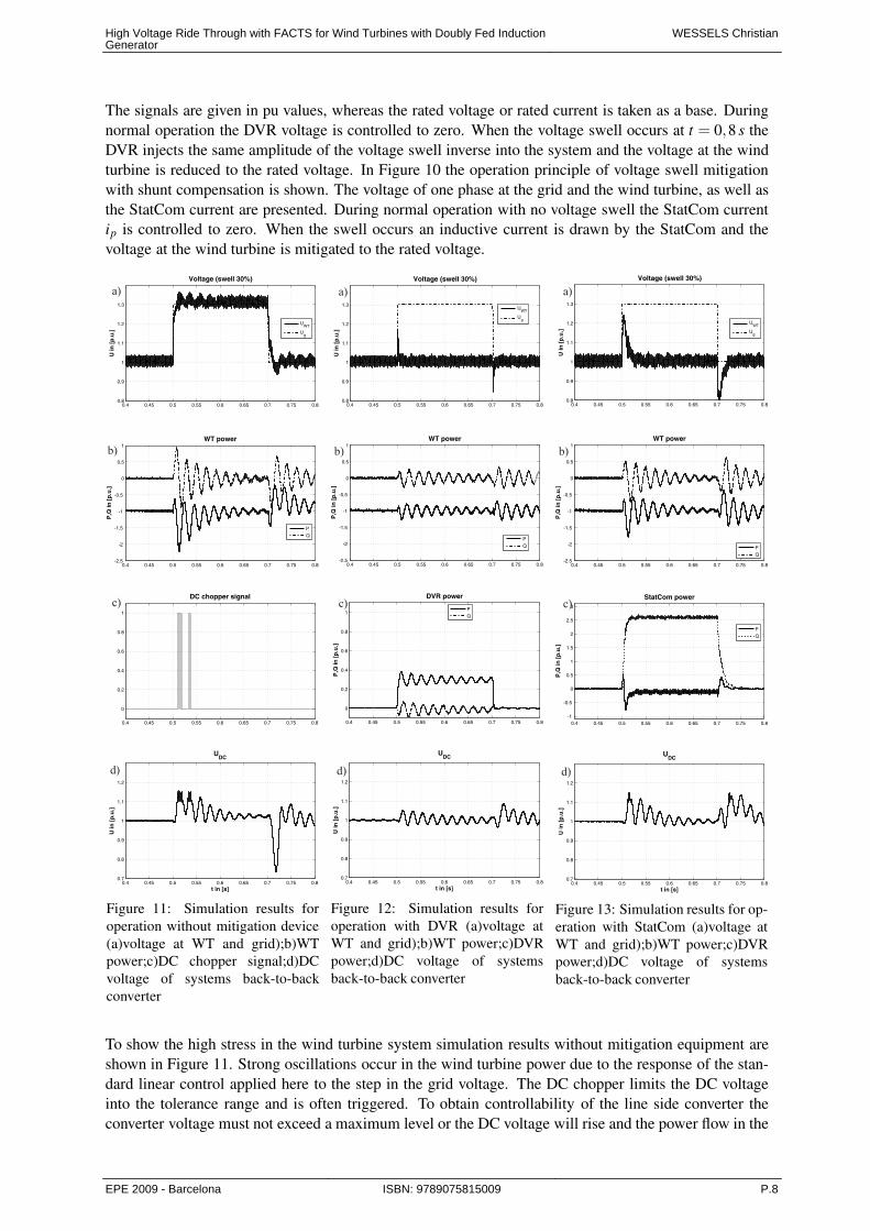
Figure 11: Simulation results for
operation without mitigation device
(a)voltage at WT and grid);b)WT
power;c)DC chopper signal;d)DC
voltage of systems back-to-back
converter
Figure 12: Simulation results for
operation with DVR (a)voltage at
WT and grid);b)WT power;c)DVR
power;d)DC voltage of systems
back-to-back converter
Figure 13: Simulation results for op-
eration with StatCom (a)voltage at
WT and grid);b)WT power;c)DVR
power;d)DC voltage of systems
back-to-back converter
To show the high stress in the wind turbine system simulation results without mitigation equipment are
shown in Figure 11. Strong oscillations occur in the wind turbine power due to the response of the stan-
dard linear control applied here to the step in the grid voltage. The DC chopper limits the DC voltage
into the tolerance range and is often triggered. To obtain controllability of the line side converter the
converter voltage must not exceed a maximum level or the DC voltage will rise and the power flow in the
High Voltage Ride Through with FACTS for Wind Turbines with Doubly Fed InductionGenerator
WESSELS Christian
EPE 2009 - Barcelona ISBN: 9789075815009 P.8
converter will be reversed. Here, the DC voltage does not rise to 1,3 p.u. due to the additional voltage
drop across the line filter, but the control is pushed towards its controllability limit and the DC voltage
rises to approximately 1,03 p.u. after the oscillations are damped. In Figure 12 the operation with DVR
is presented. In a) the d-component of the voltage at the wind turbine stator and the grid in rotating dq
coordinates aligned to the grid voltage angle are shown. It can be seen that the voltage swell is mitigated
after approximately t = 10 ms to the rated voltage. After the grid voltage swell is cleared at t = 0,7 s a
voltage dip occurs at the wind turbine because of the same DVR control delay time.
Figure 13 shows the simulation results for the system protected by a StatCom device. The mitigation of
the overvoltage is slightly slower compared to the performance of the DVR because of the larger control
delay time of the cascaded control. Because of the low system impedance Zl that consists of the grid and
transformer impedance the current to mitigate the 30 % voltage swell must be very high. Here it is 2,6
times the rated current of the wind turbine. Hence, the StatCom reactive power shown in Figure 13 c)
is 2,6 times the rated wind turbine power. Note that the realization of reactive power capability can be
done by a combination of StatCom, SVC and reactive power capability of the wind turbine generator, as
described in [16]. Here, the single StatCom is investigated. The active power consumption is controlled
to zero by the StatCom control. The power is calculated by using the p-q power theory in three phase
systems [18].
In contrast to that, the DVR as a solution of series compensation, draws only active power from the sys-
tem to mitigate the symmetrical voltage swell without phase angle jump (see Figure 12 c)). The reactive
power is controlled to zero. The oscillations are due to the oscillating currents in the DFIG as a response
of the standard field oriented control to the stator voltage step. Note that these oscillations may not occur
in reality due to additional damping not considered in the simulations or by advanced control algorithms,
which are not considered here. The oscillations can also be seen in the wind turbine power in Figure
(12) and (13) b), but they are damped after several grid periods. In Figure (12) and (13) d) the voltage
of the back-to-back converters DC link is shown in pu values. The rated DC-link voltage is taken as a
base. The DC voltage overshoot is 9 % for DVR and 15 % for StatCom caused by the slightly slower
performance of control. The DC chopper has to be triggered to limit the DC voltage, but not as often as
without mitigation equipment.
6 Conclusion
Addidional HVRT equipment makes wind turbine systems comply to the new HVRT grid code require-
ments without designing all turbine components to be tolerant against the higher voltage level. FACTS
devices for voltage swell mitigation at a wind turbine with doubly fed induction generator are analysed.
The power electronic devices DVR as a solution of series compensation and StatCom as shunt com-
pensation solution are selected. A three phase voltage swell without phase angle variation is analysed
theoretically and by means of simulation. Both investigated FACTS devices can protect the wind turbine
system from voltage swells at the point of common coupling. A fast compensation of the overvoltage
in about 10 ms is the result. This very short time overvoltage has to be compensated by means of other
methods. For voltage swells without phase jump the StatCom unit draws an inductive current that leads
to favourable consumption of reactive power. However, if the system impedance is low the current that
must be drawn can be a multiple of the nominal system current, making the StatCom ineconomical for
the system analysed (1 wind turbine generator at a transformer with same nominal apparent power). In
contrast to that the DVR is consuming active power in the range of a fraction of the wind turbine power
depending on the maximum amplitude of the voltage swell which makes it the more economical solu-
tion for the protection of a single wind turbine. The performance of the devices for unbalanced voltage
swells will be analysed in future work. Also a combined solution of reactive power sources like StatCom
and SVC might be applied. In order to meet all of the grid code requirements, especially the HVRT
requirements investigated in this paper, FACTS devices will play an increasingly role in the future.
High Voltage Ride Through with FACTS for Wind Turbines with Doubly Fed InductionGenerator
WESSELS Christian
EPE 2009 - Barcelona ISBN: 9789075815009 P.9

Table I: System parameters
Symbol Quantity Value
Ug grid voltage (phase-to-phase, rms) 690 V
ω Line angular frequency 2 π 50 Hz
PWT Wind turbine rated power 2 MW
n Rated speed 1800 min
St1 Wind turbine transformer rated power 2,5 MW
uk1 relative short circuit voltage of wind turbine transformer 6 %
St2 Wind park transformer rated power 2,5 MW
uk2 relative short circuit voltage of wind park transformer 10 %
Ssc Short curcuit power of the grid 2 GW
X/R ratio of reactance to resistance 5
fS switching frequency for LSC,DVR and StatCom 2 kHz
References
[1] Australian Energy Market Comission, National Electricity Rules, October 2008, www.aemc.gov.au[2] Bollen, Math H.J.: Understanding Power Quality Problems: Voltage Sags and Interruptions, IEEE Press
Series on Power Engineering, 2000[3] Johns, A.T.; Song, Y.H.: Flexible AC Transmission Systems, IEE Power and Energy Series 30[4] Nielsen, J.G.; Blaabjerg, F.: A detailed comparison of system topologies for dynamic voltage restorers; IEEE
Transactions on Industry Applications, Volume 41, Issue 5, Sept.-Oct. 2005 Page(s):1272 - 1280[5] Johal, H.; Divan, D.: Design Considerations for Series-Connected Distributed FACTS Converters; IEEE
Transactions on Industry Applications, Volume 43, Issue 6, Nov.-Dec. 2007 Page(s):1609 - 1618[6] Ghosh, A.; Ledwich, G: Structures and control of a dynamic voltage regulator (DVR); Power Engineering
Society Winter Meeting, 2001. IEEE, Volume 3, 28 Jan.-1 Feb. 2001 Page(s):1027 - 1032[7] Choi, S.S.; Li, J.D.; Vilathgamuwa, D.M: A generalized voltage compensation strategy for mitigating the
impacts of voltage sags/swells; IEEE Transactions on Power Delivery, Volume 20, Issue 3, July 2005
Page(s):2289 - 2297[8] Awad, H.; Svensson, J.; Bollen, M.: Mitigation of unbalanced voltage dips using static series compensator;
IEEE Transactions on Power Electronics, Volume 19, Issue 3, May 2004 Page(s):837 - 846[9] Woo, Sung-Min; Kang, Dae-Wook; Lee, Woo-Chol; Hyun, Dong-Seok: The distribution STATCOM for
reducing the effect of voltage sag and swell; Industrial Electronics Society, 2001. IECON ’01. The 27th
Annual Conference of the IEEE; Volume 2, 29 Nov.-2 Dec. 2001 Page(s):1132 - 1137 vol.2[10] Han, Chong; Huang, A.Q.; Baran, M.E.; Bhattacharya, S.; Litzenberger, W.; Anderson, L.; Johnson, A.L.;
Edris, A.: A STATCOM Impact Study on the Integration of a Large Wind Farm into a Weak Loop Power
System; IEEE Transaction on Energy Conversion, Volume 23, Issue 1, March 2008 Page(s):226 - 233[11] Ortiz, Abnery; Aredes, Mauricio; Rolim, Luis G.B.; Bueno, Emilio; Rodriguez, Pedro: A new current
control for the STATCOM based on secondary order generalized integrators; Power Electronics Specialists
Conference ’08, Rhodes[12] Alvarez, Ortega, Carlos: Voltage dip mitigation at Wind Farms; EWEC 2007, Milan[13] Ravi, S.V ; Kumar; Nagaraju, Siva, S.: Simulation of D-StatCom and DVR in power systems; ARPN Journal
of Engineering and Applied Sciences; 2006-2007 Asian Research Publishing Network (ARPN)[14] Wessels, C.; Fuchs, F.W.: Concept and Performance of Voltage Swell Mitigation in Wind Farms with FACTS,
EWEC 2009, Marseille[15] Kazmierkowski, Marian P.: Control in Power Electronics: Selected Problems; Academic Press Inc, 2002[16] de Leon, J.A.D.; Kehrli, B.; Zalay, A.: How the Lake Bonney wind farm met ESCOSA’s, NEMMCO’s, and
ElectraNet’s rigorous interconnecting requirements, Transmission and Distribution Conference and Exposi-
tion, 2008. TD. IEEE/PES; 21-24 April 2008 Page(s):1 - 5[17] Schroder, D.: Elektrische Antriebe 2, Regelung von Antriebssystemen, Springer, 2001.[18] Akagi, H.; Watanabe, E.; Aredes, M.: Instantaneous power theory and applications to power conditioning;
IEE press, 2007
High Voltage Ride Through with FACTS for Wind Turbines with Doubly Fed InductionGenerator
WESSELS Christian
EPE 2009 - Barcelona ISBN: 9789075815009 P.10