highlighting commonalities and variabilities between ... trau pcrf pcrf interfaces (n.b: all gsm...
TRANSCRIPT
International Journal of Emerging Trends & Technology in Computer Science (IJETTCS) Web Site: www.ijettcs.org Email: [email protected], [email protected]
Volume 2, Issue 1, January – February 2013 ISSN 2278-6856
Volume 2, Issue 1 January - February 2013 Page 18
Abstract: Cellular communication domain is growing in a very overwhelming manner. Contrariwise, there are limitations with current research attempts and approaches to reduce complexity [1], improve shared understanding of the domain [2], and propose a reliable solution towards achieving interoperability between different cellular network technologies. The already mentioned situation incited us to brainstorm about the subject and try to find a way to express the network architecture concepts, classes, and properties in a formal and unambiguous way. We end up by proposing a solution based on “the marriage” of cellular network technologies with ontology as a promising artificial intelligence technique for reasoning and modeling [3]. Therefore, this paper illustrates a part of an ongoing project that tends to establish a Secure Holistic Framework for Cellular Communication (SHFCC). It focuses on highlighting commonalities and variabilities between cellular communication technology architectures via the use of ontology mapping process. Keywords: ontology, feature modeling, GSM, UMTS R 99, Lte-Advanced.
1. INTRODUCTION Architectures of cellular communication network technologies are becoming more diversified then before. They are structured in such a way that the introduction of new elements and services dramatically increase their complexity [4]. Several network technologies exist in mobile communication environment. Each technology brings along with it new features, which further contribute to the complexity of the network architectures. Besides, the management of the network elements is becoming fairly difficult and the network planning and maintenance expenses are also increasing exponentially. Essential problems to overcome and work around, are to some extent those problems manifested as challenges for architectures. Our research hypothesis is as follows: is it theoretically feasible to integrate a selected set of network technology architectures into a modular federation ontology in order to figure out their similarities and variabilities?
2. METHODOLOGY Throughout this portion of investigation, the research work is going through the following steps:
1. An investigation and identification of the essential characteristics (features) accounted for in the establishment of ontology for some samples of cellular communication network technologies (GSM, UMTS R 99, and LTE-Advanced).
2. The development of a feature model for each component forming the selected domain [5]. Then, the reasoning and the brainstorming about observations and information generated by feature models in order to select the commonalities and highlight the variabilities between the three cellular networks.
3. Building a detailed ontology (using essential characteristics at a finer level of granularity) for each cellular network technology [6].
4. The design of a federation ontology integrating all the components already mentioned and classifying them by pattern of belongings [7].
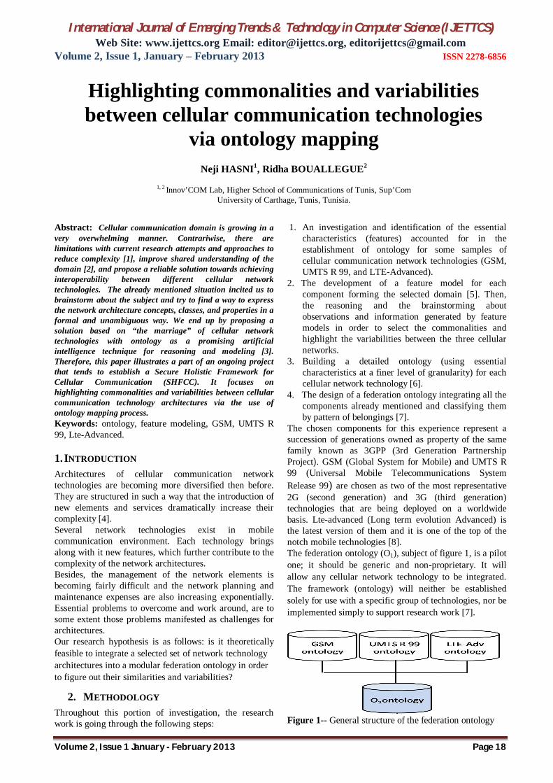
The chosen components for this experience represent a succession of generations owned as property of the same family known as 3GPP (3rd Generation Partnership Project). GSM (Global System for Mobile) and UMTS R 99 (Universal Mobile Telecommunications System Release 99) are chosen as two of the most representative 2G (second generation) and 3G (third generation) technologies that are being deployed on a worldwide basis. Lte-advanced (Long term evolution Advanced) is the latest version of them and it is one of the top of the notch mobile technologies [8]. The federation ontology (O1), subject of figure 1, is a pilot one; it should be generic and non-proprietary. It will allow any cellular network technology to be integrated. The framework (ontology) will neither be established solely for use with a specific group of technologies, nor be implemented simply to support research work [7].
Figure 1-- General structure of the federation ontology
Highlighting commonalities and variabilities between cellular communication technologies
via ontology mapping
Neji HASNI1, Ridha BOUALLEGUE2
1, 2 Innov’COM Lab, Higher School of Communications of Tunis, Sup’Com
University of Carthage, Tunis, Tunisia.
International Journal of Emerging Trends & Technology in Computer Science (IJETTCS) Web Site: www.ijettcs.org Email: [email protected], [email protected]
Volume 2, Issue 1, January – February 2013 ISSN 2278-6856
Volume 2, Issue 1 January - February 2013 Page 19
3. RESULTS: 3.1 Inferences, deducted results and ascertainments After performing a logical brainstorming around concepts and their commonalities, important results was deducted from reasoning and some inferences are concluded. Critical concepts, crucial for interoperability realization purposes, were highlighted.
3.1.1 Commonalities and variabilities between the three cellular network technologies
GSM forms the foundation technology upon which UMTS R 99 was built [9]. While UMTS R 99 and Lte-advanced networks are similar in many respects, but the terms they use are very different. GSM, UMTS R 99 and Lte-advanced all three of them were created by the 3GPP standards body. Therefore, there are numerous similarities, but there are also some variability. GSM is a circuit switched network. Meanwhile, UMTS and Lte-advanced are designed to offer high-speed packet data services to mobile subscribers. They have taken similar approaches to solving some of the challenges they both face. Whoever familiar with UMTS R 99 will have an easier time to understand Lte–advanced simply by using this holistic framework (ontology) and by learning the meaning and the functionalities of key Lte-advanced terms and mapping them with their UMTS R 99 counter parts. The greatest differences between GSM, UMTS R 99 and Lte-advanced lie in the air interface. GSM is TDMA/FDMA based system. UMTS is a WCDMA-based system, while Lte-advanced is a scalable OFDMA system. The physical layer descriptions of these two technologies (UMTS R 99 and Lte-advanced) are quite different. However, Since GSM forms the basis for UMTS R 99 system; both of them have similar physical layers. Lte-advanced and UMTS R 99 core networks are more similar than they are different; both are based on IP protocols and support seamless access to packet-based services. GSM is circuit switched system which is incorporated into UMTS R 99 network architecture. The following table 1 take the UMTS R 99 network architecture’s concepts and provide the corresponding GSM and Lte-advanced equivalents. In some cases, there is a one-to-one match between GSM and UMTS R 99 or between Lte-advanced and UMTS R 99; in others, there simply is no equivalent concept. In most cases, however, there is generally something within GSM or UMTS R 99 or within both of them that performs a function similar to its Lte-advanced counterpart, under a different name or in a different location. A simple comparison like what is presented in table 1 does not convey the real complexity of cellular network technologies’ concepts; a more detailed understanding of three network technologies (GSM, UMTS R 99, and Lte-advanced) architectures and interfaces, is required to thoroughly appreciate both the commonalities and the
variabilities between them. This holistic understandability is offered by the ontology subject of this research paper. Nevertheless, the fact that GSM, UMTS R 99 and Lte-advanced concepts can be laid out side-by-side in the way shown by the table should help to reassure all stakeholders in the domain that the evolution from GSM to UMTS R 99 is straightforward. Moreover, from UMTS to Lte-advanced is not as big a leap as one may have thought. As a general ascertainment the move from 2G to 3G and from 3G to 4G is smooth and not a big deal unless we don’t understand the domain. 3.1.2 Interoperation ascertainments For interworking purposes, Lte-advanced relies on
an evolved packet core network which allows interoperation with various access technologies like GSM and UTRAN as well as CDMA2000 [10].
Since Lte-advanced does not support soft handover, there is no need for a centralized data combining function in the network. As a consequence, if the UE moves, the network must transfer all information related to a UE, from one eNB to another.
Different implementations of protocols can interoperate because of standard interfaces such as (Um, Abis, and A for GSM) between protocols.
The GSM and UMTS networks are usually tightly interconnected and work in a similar fashion in order to ease interoperability.
There are inter-technology handovers between UMTS and Lte-advanced. Two interfaces are provided for the interworking. The S3 reference point is based on the legacy Gn interface. The S4 reference point is based on the older Gn interface of UMTS, and lies between the SGSN in the GPRS core network and the SGW [11]. The preferred way to interwork UMTS with Lte-advanced is through SGSN. It deploys the S3, S4.
Intra-Lte-advanced (Intra-MME / SGW) handover using the X2 Interface [28]: This procedure is used to handover a UE from a source eNodeB to a target eNodeB using the X2 interface when the Mobility Management Entity (MME) and Serving Gateway (SGW) are unchanged. It is possible only if direct connectivity exists between the source and target eNodeB’s with the X2 interface.
Intra-Lte-advanced (Intra-MME / SGW) handover using the S1 Interface: The S1-based handover procedure is used when the X2-based handover cannot.
The proper interworking between UMTS R 99 RAN and GSM CN is achieved only when the network elements on both sides (RNC, MSC and SGSN) act according to a predefined set of rules; such standards define how each element in the network shall react upon receiving information from another element.

International Journal of Emerging Trends & Technology in Computer Science (IJETTCS) Web Site: www.ijettcs.org Email: [email protected], [email protected]
Volume 2, Issue 1, January – February 2013 ISSN 2278-6856
Volume 2, Issue 1 January - February 2013 Page 20
Table 1--Comparing GSM, UMTS Release 99, and Lte-advanced Properties GSM UMTS Release 99 Lte-advanced
Network Architecture LAN Wide area cell-based Hybrid Switching PS CS & PS Digital with packetized voice Voice switching Circuit Circuit Packet Data switching Circuit Packet Packet Radio Access TDMA/FDMA WCDMA OFDMA Databases HLR,VLR, EIR, AuC EHLR, VLR, EIR, AuC EHLR, VLR, EIR, AuC Roaming Restricted Global Global Component design Optimized antenna Optimized antenna Smarter Antennas Technology digital digital digital Data rates 236,8 kbps 384 kbps Up to 1 Gbps
Networks Architecture Components GSM UMTS Release 99 Lte-advanced Comments
SIM USIM USIM MS ME ME MS UE UE BSS RNS Few BTS NODE B +RNC eNODE B One NodeB is less autonomous than BTS. eNodeB
assures the functions of NodeB (3G) and some functions of RNC (3G).
BSC & BTS UTRAN eUTRAN MSC MSC VLR VLR VLR HLR EHLR HSS/EHLR HSS is an enhanced HLR; It contains subscriber profile
for 2G, 3G, Lte-advanced… SGSN MME/SGW An SGW functionally resembles to a 3G/SGSN without
the mobility and the session control features. GGSN PGW MSC MSC MME MME: Somewhat analogous to the distribution of control
and bearer data of the MSC, Lte-advanced separates control from bearer in the design of the EPC.
NSS CN EPC PSTN PSTN PSTN PDN PDN PDN BSC RNC RNC is more complicated than BTS because it controls
node Bs totally.
Eir Eir Eir AuC AuC AuC PS/CN EPC OMC OMC TRAU TRAU PCRF PCRF
Interfaces (N.B: All GSM interfaces are found in UMTS R99) Iub and Iur X2 interface Between two eNodeBs. It prevent the loss of data when
changing eNodeB A A/Iu S1 Between BSC (RNC) and Core Network Um Uu Uu Between BTS and MS Abis Iub X2 Between BTS and BSC (NodeB-RNC) Does not exist Iur X2 Between two RNCs Gn/Gp S5/S8 A configured traffic path between the SGW and the
PDNGW IMSI IMSI IMSI International Mobile Subscriber Identity consists of
Mobile Country Code (MCC), Mobile Network Code (MNC), and Mobile Identification Number (MIN).
IMEI IMEI IMEI International Mobile Equipment Identity. Downlink (DL) Downlink (DL) Transmission from the network to the mobile.
Uplink (UL) Uplink (UL) Transmission from the mobile to the network. NAS GSM NAS UMTS NAS UMTS = NAS GSM+ functional evolution Scrambling Physical layer Unique cell identifier.

International Journal of Emerging Trends & Technology in Computer Science (IJETTCS) Web Site: www.ijettcs.org Email: [email protected], [email protected]
Volume 2, Issue 1, January – February 2013 ISSN 2278-6856
Volume 2, Issue 1 January - February 2013 Page 21
code Cell ID
4. CELLULAR NETWORK TECHNOLOGIES ANALYSIS
The approach to developing a federation ontology starts by analyzing the architectures of the subset of technologies (GSM, UMTS R 99, and Lte-advanced), performing a domain analysis of them before building feature models one for each cellular network technology.
4.1 Analysis of GSM network architecture GSM is an abbreviation of Global System for Mobile Communication, originally known as Group Special Mobile. It is a second generation digital cellular system. It uses digital transmission rather than analog transmission. GSM networks use a combination of FDMA (Frequency Division Multiple Access) and TDMA (Time Division Multiple Access) [12]. The GSM network technology is composed of three functional entities operating with each other. These entities are called: the Network and Switching Subsystem (NSS), the Radio Subsystem (RSS), and the Operation Support Subsystem (OSS). Figure 2 shows the global architecture of the GSM network. However, for analysis and modularity purposes, the GSM network architecture is further divided into domains.
Figure 2--GSM network architecture [8].
GSM’s protocol architecture is characterized by the presence of planes [12]: The user plane: contain the protocols for data transmission, and the control plane offers signalling for transmission supervision and establishment. Then, the management plane which allows the coordination between the two previous planes. The GSM protocol stacks are illustrated in the following figure 3:
Figure 3--GSM Protocol Stack [8].
4.2 Analysis of UMTS R 99 network architecture
UMTS R 99 is the successor of GSM. It is a third generation (3G) mobile communication system. It has been standardized in several releases. The first version is - Release 99-. UMTS network can be divided into two parts. One part is responsible for the circuit switched services (CS-domain) and the other one manages the packet switched services (PS-domain). The CS-domain manages voice calls meanwhile the PS-domain is responsible for data connection like the connection from a mobile device to the internet [13]. UMTS introduces a new wireless access technology, namely the WCDMA. The major headlines for Release 99 are:
• Definition of the UMTS Universal Terrestrial Radio Access Network (UTRAN),
• The Radio Network Subsystem (RNS) is added to the existing GSM network,
The general UMTS network architecture is modeled, at a high level, from both physical and functional viewpoints. The physical aspects are modeled using the domain concept and the functional aspects are modeled using the strata concept. A stratum: is a grouping of protocols related to one aspect of the services provided by one or several domains [14]. Figure 4 elucidates the global architecture of UMTS R 99.
Figure 4--UMTS R 99 network architecture.
UMTS R99 strata: A Stratum is a way of grouping protocols related to one aspect of services provided by one or several domains. Different UMTS strata are illustrated by figure 5 jointly with detailed description [15]:
Figure 5-- UMTS protocol stacks [16].

International Journal of Emerging Trends & Technology in Computer Science (IJETTCS) Web Site: www.ijettcs.org Email: [email protected], [email protected]
Volume 2, Issue 1, January – February 2013 ISSN 2278-6856
Volume 2, Issue 1 January - February 2013 Page 22
1. Transport stratum: supports the transport of the user data and the network control signalling from other strata through UMTS. It encompasses the access stratum, which is the part of the transport stratum located between the edge node of the serving core network domain and the MT (Mobile Termination).
– Access stratum: protocol handling activities between UE and access network. It provides services related to the transmission of data over the radio interface and the management of it.
2. Serving stratum: consists of protocols and functions that transmit the data/information from the source to the destination.
3. Home stratum: contains the protocols and functions related to the handling and storage of subscription data and possibly home network specific services;
4. Application stratum: represents the application process itself, provided to the end-user. It includes end-to-end protocols and functions which make use of services provided by the home, serving and transport strata and infrastructure to support services and/or value added services.
4.3 Analysis of Lte-advanced network architecture
Lte-advanced network technology was standardized by the 3rd Generation Partnership Project (3GPP), and endorsed by the International Telecommunications Union (ITU) as a fourth generation. The main objective of the Lte-advanced is to meet the challenge of increasing number of heterogeneous devices that requires higher bandwidth as well as heterogeneous networks. It is based on Orthogonal Frequency Division Multiplexing technology (OFDM). OFDM allows transmitting large amounts of digital data over a radio wave. An important aspect of Lte-advanced has been the introduction of a new Radio Access Network (RAN) architecture, called the evolved Universal Terrestrial Radio Access Network or eUTRAN (also eUTRA). An important characteristic of eUTRAN is the Base Stations, known as evolved NodeBs (eNBs), which perform the functions of the NodeB’s as well as the RNCs of the UMTS. A new packet core, the Evolved Packet Core (EPC) has been introduced to support the eUTRAN. MMEs and SGWs are the pivotal nodes in the control and user plane respectively, in this new architecture. They are responsible for packet forwarding, routing, inter-Radio Access Technology (RAT) connections, identity (ID) verification, User Equipment (UE) tracking etc. The rationale for this approach is that it leads to a reduction in the number of network elements, simpler functionality and improved redundancy. This is apart from allowing connections and handovers to other fixed line and RATs [18]. The Lte-advanced protocol architecture is made up of two planes: the user plane, which provides functions such as formatting user traffic between User Equipment (UE) and the evolved Universal Terrestrial Radio Access Network (eUTRAN); and the control plane, which support
functions used for control purposes such as network authentication. Protocol architecture of Lte-advanced network is shown in figure 7 (a) and (b), consisting of user plane and control plane. The relay protocol stacks are taken into consideration since its protocol’s functions depend on types of relaying schemes used, while we are dealing with general situation.
Figure 6-- Lte-adv network architecture (after [19]).
a) Lte-advanced user plane protocol architecture.
b) Lte-advanced control plane protocol architecture.
Figure 7--Lte-advanced protocols’ achitecture. 4.4 Feature modeling Feature modeling is one of the most crucial and popular outcomes of the domain analysis techniques, which constructs variability and commonality in a domain. The output of feature modeling will be some reusable assets (components, patterns, etc.) represented as a feature diagram. However, feature modeling can be difficult and time-consuming without a precise understanding of its goals and the aid of practical guidelines [20]. Different domain analysis methods use the term “feature” with slightly different meanings. Feature-Oriented Domain Analysis (FODA) defines a feature as a prominent and distinctive user visible characteristic of a system. According to [21], common features among different products are modeled as mandatory features, while
International Journal of Emerging Trends & Technology in Computer Science (IJETTCS) Web Site: www.ijettcs.org Email: [email protected], [email protected]
Volume 2, Issue 1, January – February 2013 ISSN 2278-6856
Volume 2, Issue 1 January - February 2013 Page 23
different features among them may be optional or alternative. Optional features represent selectable features for products of a given domain and alternative features indicate that no more than one feature can be selected for a product. A feature diagram captures structural or conceptual relationships among features. Three types of relationships are represented in this diagram. The “composed-of” relationship used if there is a whole-part relationship between a feature and its sub-features. In cases where features are generalization of sub-features, they are organized using the “generalization/specialization” relationship. The “implemented-by” relationship is used when a feature is necessary to implement another feature.
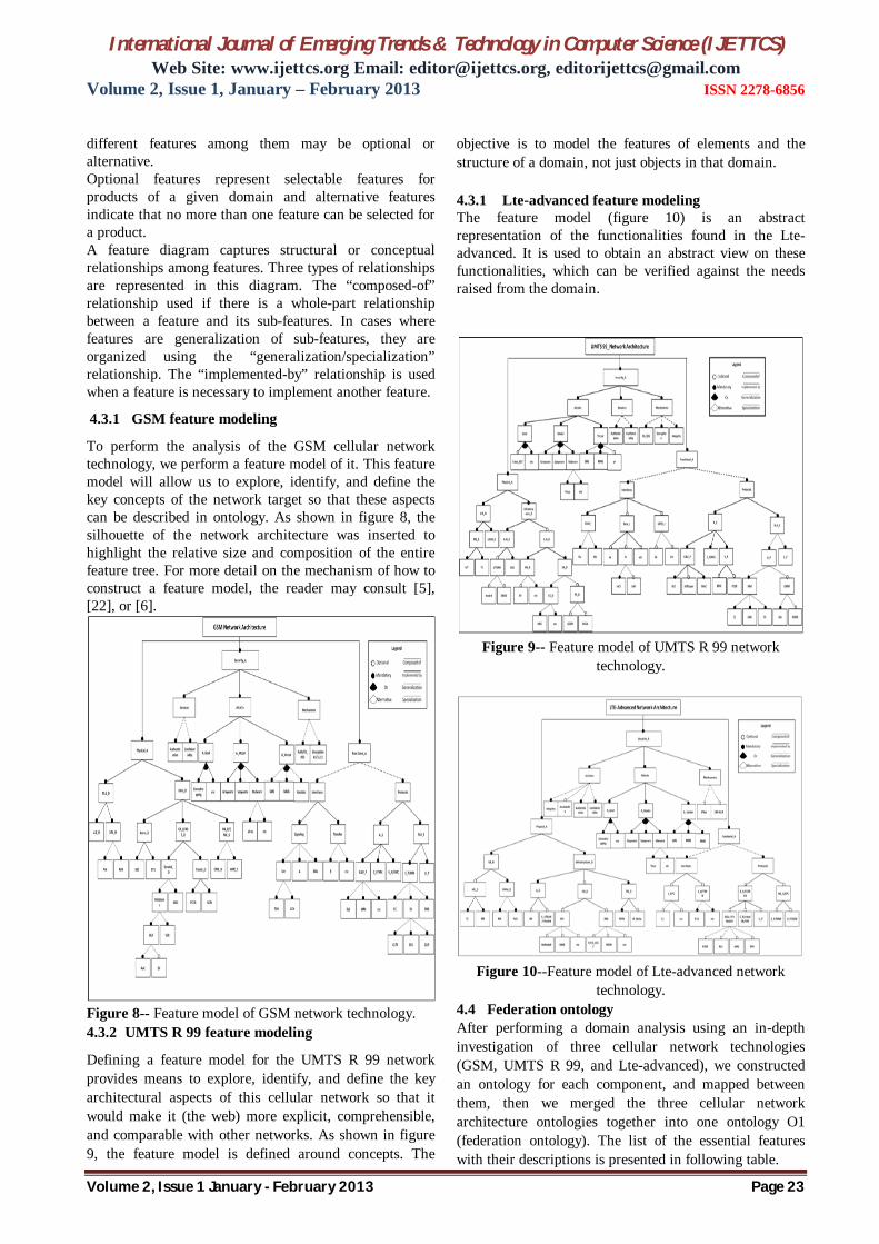
4.3.1 GSM feature modeling
To perform the analysis of the GSM cellular network technology, we perform a feature model of it. This feature model will allow us to explore, identify, and define the key concepts of the network target so that these aspects can be described in ontology. As shown in figure 8, the silhouette of the network architecture was inserted to highlight the relative size and composition of the entire feature tree. For more detail on the mechanism of how to construct a feature model, the reader may consult [5], [22], or [6].
Figure 8-- Feature model of GSM network technology. 4.3.2 UMTS R 99 feature modeling
Defining a feature model for the UMTS R 99 network provides means to explore, identify, and define the key architectural aspects of this cellular network so that it would make it (the web) more explicit, comprehensible, and comparable with other networks. As shown in figure 9, the feature model is defined around concepts. The
objective is to model the features of elements and the structure of a domain, not just objects in that domain. 4.3.1 Lte-advanced feature modeling The feature model (figure 10) is an abstract representation of the functionalities found in the Lte-advanced. It is used to obtain an abstract view on these functionalities, which can be verified against the needs raised from the domain.
Figure 9-- Feature model of UMTS R 99 network
technology.
Figure 10--Feature model of Lte-advanced network
technology. 4.4 Federation ontology After performing a domain analysis using an in-depth investigation of three cellular network technologies (GSM, UMTS R 99, and Lte-advanced), we constructed an ontology for each component, and mapped between them, then we merged the three cellular network architecture ontologies together into one ontology O1 (federation ontology). The list of the essential features with their descriptions is presented in following table.

International Journal of Emerging Trends & Technology in Computer Science (IJETTCS) Web Site: www.ijettcs.org Email: [email protected], [email protected]
Volume 2, Issue 1, January – February 2013 ISSN 2278-6856
Volume 2, Issue 1 January - February 2013 Page 24
Table 2-- list of essential features of the federation ontology
Feature Full name of the feature
Description
NTA Network Technology Architecture
Network Technologies Architecture (NTA) : for the purpose of this study, we choose: Global System for Mobile Communications (GSM) -a Second generation cellular technology based on both protocols: Frequency Division Multiple Access Analog technology (FDMA), and Time Division Multiple Access Digital technology (TDMA)-, UMTS (Universal Mobile Telecommunications System) -a third generation cellular technology based on Code Division Multiple Access technology (CDMA), and Lte-advanced (Long-term evolution-advanced) - a fourth generation cellular technology, based on Orthogonal Frequency Division Multiplexing technology (OFDM)-. However, this is a pilot study which may extended by integrating other network technologies architectures.
Functional_A
Functional_Architecture
The functional architecture of a system can be broadly divided into interfaces and their specified protocols.
Interfaces Interfaces The main role of network interfaces or reference points interfaces is the connection between different domains.
EPC_I EPC_Interfaces The interfaces interconnecting the functional elements of the core network. Gx Gx Rx Rx The Rx is the Diameter-based interface between an Application Function (AF), usually in a
Proxy Call Session Control Function (PCSCF). S1 S1 The S1 interface connects the eNodeB to the EPC. It is split into two interfaces, one for the
control plane and the other for the user plane. S1-mme S1-mme The reference point for the control plane protocol between the E-UTRAN and the MME. S10 S10 Reference point between MMEs for MME relocation and MME to MME information
transfer. S11 S11 Reference point between MME and SGW. S3 S3 The S3 reference point is based on the legacy Gn interface. It lies between the SGSN and the
MME where it enables user and bearer information exchanges for inter-3GPP access system mobility.
S4 S4 The S4 reference point lies between the SGSN in the GPRS core network and the SGW. S5 S5 The reference point between the SGW and the PGW. It provides user plane tunneling and
tunnel management between SGW and PDNGW. It is used for SGW relocation due to UE mobility and if the SGW needs to connect to a non-collocated PDNGW for the required PDN connectivity.
S6a S6a The diameter-based reference point between the MME and the HSS. It enables transfer of subscription and authentication data.
SGi SGi The SGi is Lte-advanced’s version of the UMTS’s Gi interface between the PGW and the Packet Data Network (PDN). The PDN may be an external public or private packet data network or an intra-operator packet data network.
GPRS_I GPRS Interfaces Interfaces Gc, Gr, Gf and Gs, which originate from the GPRS system. Gb Gb interface Interface between an SGSN and a BSS. Gc Gc interface Interface between the GGSN and the HLR. Gf Gf interface The Gf interface is defined between the SGSN and EIR. It is used by the SGSN to contact the
EIR database during the identity check procedure. Gi Gi interface The Gi interface is a reference point in a GPRS Core Network. The Gi interface is IP based
and serves as a reference point between the GGSN and the Public Data Network or PDN. Gn Gn interface Interface between the SGSN and the GGSN. It is an IP-based interface used to carry
signalling and user data. Gp Gp interface Interface between the SGSN and the GGSN, in different PLMNs. Gr Gr interface Interface between the SGSN and the HLR. Gs Gs interface The interface between the SGSN and the MSC/VLR. A A interface The A interface is used to provide communication between the BSS and the MSC. The
interface carries information to enable the channels, timeslots to be allocated to the mobile equipments being serviced by the BSSs. The messaging required within the network to enable handover is carried over the interface. Its primary functions: message transfer between different BSCs to the MSC.
Abis Abis interface This is a BSS internal interface linking the BSC and a BTS, and it has not been totally

International Journal of Emerging Trends & Technology in Computer Science (IJETTCS) Web Site: www.ijettcs.org Email: [email protected], [email protected]
Volume 2, Issue 1, January – February 2013 ISSN 2278-6856
Volume 2, Issue 1 January - February 2013 Page 25
standardized. The Abis interface allows control of the radio equipment and radio frequency allocation in the BTS.
Um Air interface The "air" or radio interface standard that is used for exchanges between a mobile and a base station.
CCH CCH Logical channel: Used for signalling between the BTS and the MS and to request and grant access to the network.
TCH Speech traffic channel
logical channel, Traffic channels carry user information (– speech, data, FAX)
Specific_UMTS_I
Specific_UMTS_Interfaces
New interfaces relatively to GSM and GPRS.
Cu Cu Reference point between USIM and ME. Iu Iu Reference point between access and serving network domains. IuCS IuCs-interface Interface between the MSC and the RNS. It connects the RNC to the circuit switched part of
the CN. IuPS IuPs-interface Interface between the SGSN and the RNS. It connects the RNC to the packet switched part of
the CN. Iur Iur Logical interface between two RNCs. Yu Yu Reference point between Serving and Transit Network domains. Zu Zu Reference point between Serving and Home Network domains. B B interface The B interface exists between the MSC and the VLR. C C interface The C interface is located between the HLR and a MSC. D D interface The D interface is situated between the VLR and HLR. E E interface The E interface provides communication between two MSCs. The E interface exchanges data
related to handover between the anchor and relay MSCs. F F interface Is used between an MSC and EIR. G G interface The G interface interconnects two VLRs of different MSCs. H H interface The H interface exists between the MSC the SMS-G. eUTRAN_I
Interfaces eUTRAN
Interfaces between components belonging to the eUTRAN sytem.
S1-U S1-U Reference point between EUTRAN and SGW for the per-bearer user plane tunneling and inter-eNB path switching during handover.
Uu air interface The Lte-advanced-Uu provides the reference point for the radio interface between the UE and eNB. It encompasses the control plane and user plane. The signalling connection across the Lte-advanced-Uu interface is the Radio Resource Control (RRC) signalling connection, which is stacked into the Packet Data Convergence Protocol (PDCP), Radio Link Control (RLC) and Media Access Control (MAC) layers. The PDCP, RLC, and MAC layers constitute the user plane protocols for the air interface.
X2 X2 The X2 interface is used to interconnect eNodeBs. It may be established between one eNodeB and some of its neighbor eNodeBs in order to exchange signalling information when needed.
Protocols Protocols Protocols are to define how different elements are able to communicate over the interfaces. Access_Stratum
Access_Stratum Represents the application process itself. It includes end-to-end protocols and functions which make use of services provided by the home, serving and transport strata and infrastructure to support services and/or value added services.
C&U_P C&U_P A protocol is a set of rules according to which messages are transmitted between two or more entities on a network.
MAC Media Access Control
MAC protocol controls the access signalling (request and grant) procedures for the radio channel.
PDCP PDCP Packet Data Convergence Protocol: provides protocol transparency for higher-layer protocols, support for e.g., IPv4, and IPv6 (easy introduction of new higher layer protocols), and compression of control information (header compression).
PHY Physical layer The physical layer implements OFDMA scheme on the downlink for high spectral efficiency, robustness against frequency-selectivity and multi-path interference. It supports flexible bandwidth deployment, facilitates frequency-domain scheduling and is well suited for Multiple Input Multiple Output (MIMO) techniques.
RLC Radio Link Control
RLC protocol provides logical link control over the radio interface.
C_P C_P Control Plane Protocols (that control the calls). U_P U_P User plane protocols (that carry the user's data). The functions that deal with issues of user-
to-user information transfer and associated controls such as flow control and error control mechanisms.
Non_Access_Strat
Non_Access_Stratum
Is a functional layer between core network and user equipment. The layer supports signalling and traffic between those two elements.

International Journal of Emerging Trends & Technology in Computer Science (IJETTCS) Web Site: www.ijettcs.org Email: [email protected], [email protected]
Volume 2, Issue 1, January – February 2013 ISSN 2278-6856
Volume 2, Issue 1 January - February 2013 Page 26
um C_P C_P Responsible for location management and Security. Involves the procedures and signalling
for location updating. GMM GMM This protocol is a variant of the GPRS GMM protocol. UMTS and GPRS use the GSM MM
(Mobility Management) protocol. Here, it is known as the GPRS MM protocol (GMM). The main function of the MM sub-layer is to support the mobility of user terminals, such as informing the network of its present location and providing user identity confidentiality. A further function of the GMM sub-layer is to provide connection management services to the different entities of the upper Connection Management (CM) sub-layer.
GMSC Gateway Mobile Service Switching Centre
Its services are similar to the GGSN as the gateway towards external circuit switched networks like other public land mobile networks (PLMNs) and integrated service digital networks (ISDNs)…etc. The GMSC is responsible for collecting the location information and routing the call to the MSC through which the subscriber can obtain service at that instant.
SM Session Management.
This protocol is a variant of the GPRS SM protocol. SM handles mobility issues such as roaming, authentication, selection of encryption algorithms and maintains PDP context.
MM MM The protocols in the MM layer involve the USIM, MSC, VLR, and the HLR, as well as the AuC.
CC CC It is a protocol that controls the establishment and release of circuit switched calls in the CN domain.
SMS SMS Controls the delivery of short text messages to and from UEs. SS SS Protocol that controls the activation and deactivation of various call-related and non call-
related supplementary services. CFU Call forwarding
– unconditional Permits a called subscriber to send incoming calls addressed to the called subscriber’s Directory Number to another Directory Number. If this feature is active, calls are forwarded regardless of the condition of the termination. CFU does not impact a subscriber’s ability to originate calls.
CLIP Calling line identification presentation
Is a supplementary GSM service used to show the number of a caller.
U_P User Plane The functions that deal with issues of user-to-user information transfer and associated
controls such as flow control and error control mechanisms. GMM GPRS Mobility
Management. This protocol is a variant of the GPRS GMM protocol. UMTS and GPRS use the GSM MM (Mobility Management) protocol. Here it is known as the GPRS MM protocol (GMM). The main function of the MM sub-layer is to support the mobility of user terminals, such as informing the network of its present location and providing user identity confidentiality. A further function of the GMM sub-layer is to provide connection management services to the different entities of the upper Connection Management (CM) sub-layer.
GSMS GSMS Its services are similar to the GGSN as the gateway towards external circuit switched networks like other public land mobile networks (PLMNs) and integrated service digital networks (ISDNs)…etc. The GMSC is responsible for collecting the location information and routing the call to the MSC through which the subscriber can obtain service at that instant.
SM Session Management.
This protocol is a variant of the GPRS SM protocol. SM handles mobility issues such as roaming, authentication, selection of encryption algorithms and maintains PDP context.
MM Mobility Management
The protocols in the MM layer involve the USIM, MSC, VLR, and the HLR, as well as the AuC.
CC Call Control It is a protocol that controls the establishment and release of circuit switched calls in the CN domain.
SMS Short Message Service
Controls the delivery of short text messages to and from UEs.
SS Supplementary Service
Protocol that controls the activation and deactivation of various call-related and non call-related supplementary services.
CFU CFU Permits a called subscriber to send incoming calls addressed to the called subscriber’s Directory Number to another Directory Number. If this feature is active, calls are forwarded regardless of the condition of the termination. CFU does not impact a subscriber’s ability to originate calls.
CLIP CLIP Is a supplementary GSM service used to show the number of a caller. Physical_Architecture
Physical_Architecture
Physical nodes which perform various functions to support communication services.
Infrastruc Infrastructure_D Set of all the network entities, composed of: the access network domain, the entities closely
International Journal of Emerging Trends & Technology in Computer Science (IJETTCS) Web Site: www.ijettcs.org Email: [email protected], [email protected]
Volume 2, Issue 1, January – February 2013 ISSN 2278-6856
Volume 2, Issue 1 January - February 2013 Page 27
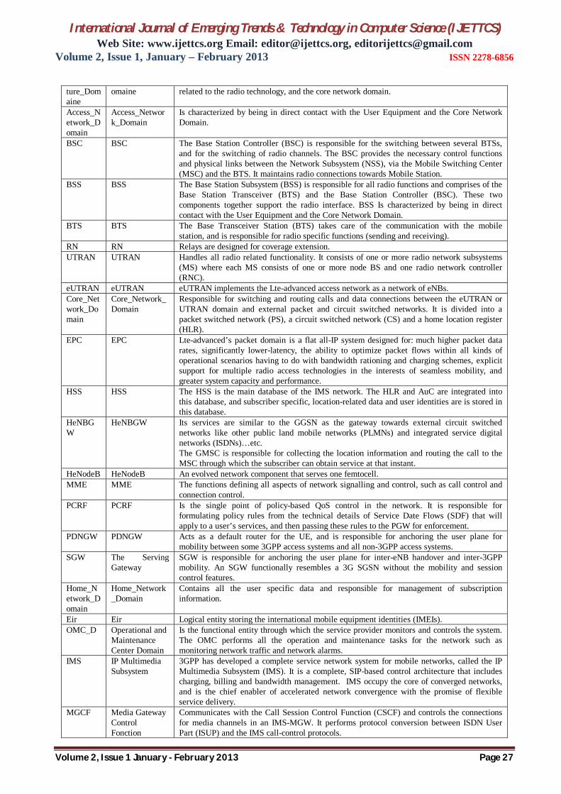
ture_Domaine
omaine related to the radio technology, and the core network domain.
Access_Network_Domain
Access_Network_Domain
Is characterized by being in direct contact with the User Equipment and the Core Network Domain.
BSC BSC The Base Station Controller (BSC) is responsible for the switching between several BTSs, and for the switching of radio channels. The BSC provides the necessary control functions and physical links between the Network Subsystem (NSS), via the Mobile Switching Center (MSC) and the BTS. It maintains radio connections towards Mobile Station.
BSS BSS The Base Station Subsystem (BSS) is responsible for all radio functions and comprises of the Base Station Transceiver (BTS) and the Base Station Controller (BSC). These two components together support the radio interface. BSS Is characterized by being in direct contact with the User Equipment and the Core Network Domain.
BTS BTS The Base Transceiver Station (BTS) takes care of the communication with the mobile station, and is responsible for radio specific functions (sending and receiving).
RN RN Relays are designed for coverage extension. UTRAN UTRAN Handles all radio related functionality. It consists of one or more radio network subsystems
(MS) where each MS consists of one or more node BS and one radio network controller (RNC).
eUTRAN eUTRAN eUTRAN implements the Lte-advanced access network as a network of eNBs. Core_Network_Domain
Core_Network_Domain
Responsible for switching and routing calls and data connections between the eUTRAN or UTRAN domain and external packet and circuit switched networks. It is divided into a packet switched network (PS), a circuit switched network (CS) and a home location register (HLR).
EPC EPC Lte-advanced’s packet domain is a flat all-IP system designed for: much higher packet data rates, significantly lower-latency, the ability to optimize packet flows within all kinds of operational scenarios having to do with bandwidth rationing and charging schemes, explicit support for multiple radio access technologies in the interests of seamless mobility, and greater system capacity and performance.
HSS HSS The HSS is the main database of the IMS network. The HLR and AuC are integrated into this database, and subscriber specific, location-related data and user identities are is stored in this database.
HeNBGW
HeNBGW Its services are similar to the GGSN as the gateway towards external circuit switched networks like other public land mobile networks (PLMNs) and integrated service digital networks (ISDNs)…etc. The GMSC is responsible for collecting the location information and routing the call to the MSC through which the subscriber can obtain service at that instant.
HeNodeB HeNodeB An evolved network component that serves one femtocell. MME MME The functions defining all aspects of network signalling and control, such as call control and
connection control. PCRF PCRF Is the single point of policy-based QoS control in the network. It is responsible for
formulating policy rules from the technical details of Service Date Flows (SDF) that will apply to a user’s services, and then passing these rules to the PGW for enforcement.
PDNGW PDNGW Acts as a default router for the UE, and is responsible for anchoring the user plane for mobility between some 3GPP access systems and all non-3GPP access systems.
SGW The Serving Gateway
SGW is responsible for anchoring the user plane for inter-eNB handover and inter-3GPP mobility. An SGW functionally resembles a 3G SGSN without the mobility and session control features.
Home_Network_Domain
Home_Network_Domain
Contains all the user specific data and responsible for management of subscription information.
Eir Eir Logical entity storing the international mobile equipment identities (IMEIs). OMC_D Operational and
Maintenance Center Domain
Is the functional entity through which the service provider monitors and controls the system. The OMC performs all the operation and maintenance tasks for the network such as monitoring network traffic and network alarms.
IMS IP Multimedia Subsystem
3GPP has developed a complete service network system for mobile networks, called the IP Multimedia Subsystem (IMS). It is a complete, SIP-based control architecture that includes charging, billing and bandwidth management. IMS occupy the core of converged networks, and is the chief enabler of accelerated network convergence with the promise of flexible service delivery.
MGCF Media Gateway Control Fonction
Communicates with the Call Session Control Function (CSCF) and controls the connections for media channels in an IMS-MGW. It performs protocol conversion between ISDN User Part (ISUP) and the IMS call-control protocols.
International Journal of Emerging Trends & Technology in Computer Science (IJETTCS) Web Site: www.ijettcs.org Email: [email protected], [email protected]
Volume 2, Issue 1, January – February 2013 ISSN 2278-6856
Volume 2, Issue 1 January - February 2013 Page 28
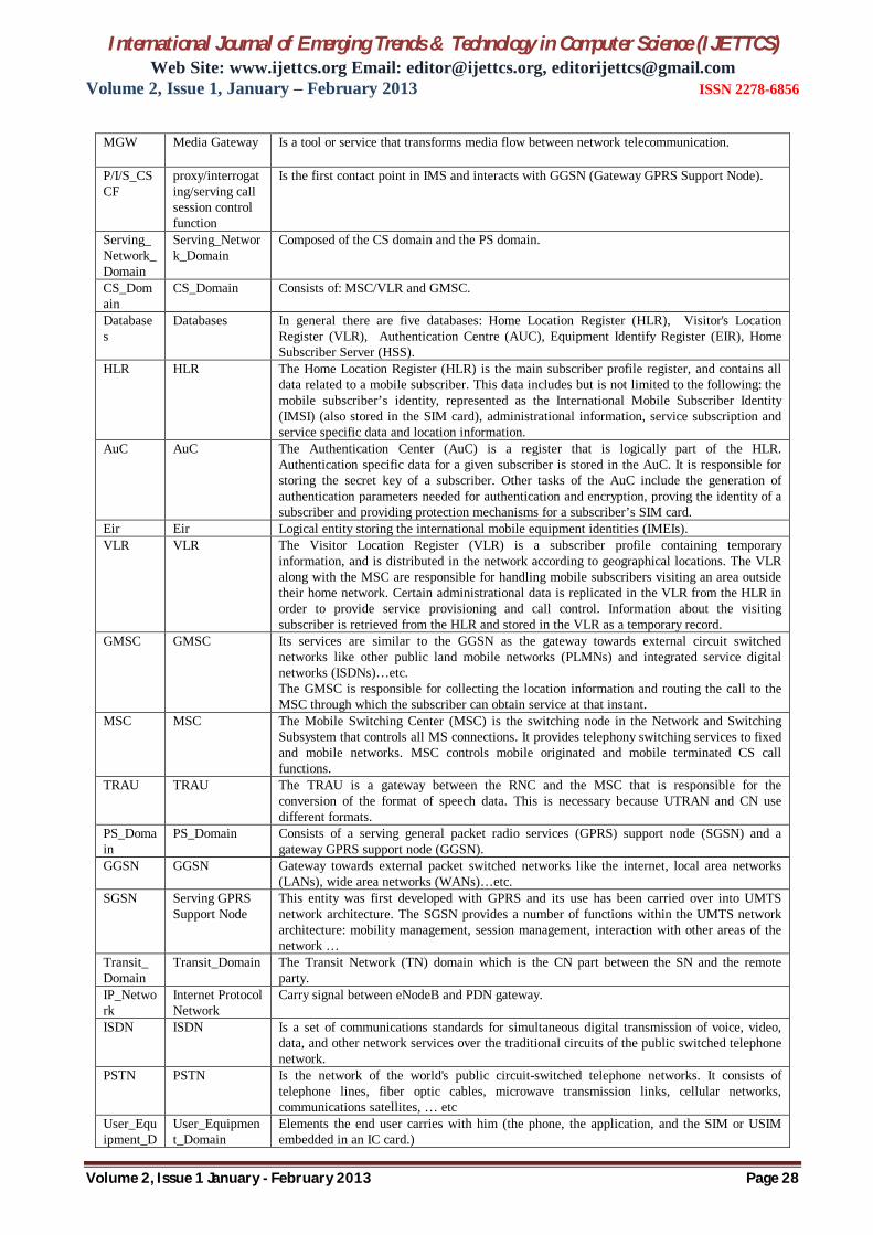
MGW Media Gateway Is a tool or service that transforms media flow between network telecommunication.
P/I/S_CSCF
proxy/interrogating/serving call session control function
Is the first contact point in IMS and interacts with GGSN (Gateway GPRS Support Node).
Serving_Network_Domain
Serving_Network_Domain
Composed of the CS domain and the PS domain.
CS_Domain
CS_Domain Consists of: MSC/VLR and GMSC.
Databases
Databases In general there are five databases: Home Location Register (HLR), Visitor's Location Register (VLR), Authentication Centre (AUC), Equipment Identify Register (EIR), Home Subscriber Server (HSS).
HLR HLR The Home Location Register (HLR) is the main subscriber profile register, and contains all data related to a mobile subscriber. This data includes but is not limited to the following: the mobile subscriber’s identity, represented as the International Mobile Subscriber Identity (IMSI) (also stored in the SIM card), administrational information, service subscription and service specific data and location information.
AuC AuC The Authentication Center (AuC) is a register that is logically part of the HLR. Authentication specific data for a given subscriber is stored in the AuC. It is responsible for storing the secret key of a subscriber. Other tasks of the AuC include the generation of authentication parameters needed for authentication and encryption, proving the identity of a subscriber and providing protection mechanisms for a subscriber’s SIM card.
Eir Eir Logical entity storing the international mobile equipment identities (IMEIs). VLR VLR The Visitor Location Register (VLR) is a subscriber profile containing temporary
information, and is distributed in the network according to geographical locations. The VLR along with the MSC are responsible for handling mobile subscribers visiting an area outside their home network. Certain administrational data is replicated in the VLR from the HLR in order to provide service provisioning and call control. Information about the visiting subscriber is retrieved from the HLR and stored in the VLR as a temporary record.
GMSC GMSC Its services are similar to the GGSN as the gateway towards external circuit switched networks like other public land mobile networks (PLMNs) and integrated service digital networks (ISDNs)…etc. The GMSC is responsible for collecting the location information and routing the call to the MSC through which the subscriber can obtain service at that instant.
MSC MSC The Mobile Switching Center (MSC) is the switching node in the Network and Switching Subsystem that controls all MS connections. It provides telephony switching services to fixed and mobile networks. MSC controls mobile originated and mobile terminated CS call functions.
TRAU TRAU The TRAU is a gateway between the RNC and the MSC that is responsible for the conversion of the format of speech data. This is necessary because UTRAN and CN use different formats.
PS_Domain
PS_Domain Consists of a serving general packet radio services (GPRS) support node (SGSN) and a gateway GPRS support node (GGSN).
GGSN GGSN Gateway towards external packet switched networks like the internet, local area networks (LANs), wide area networks (WANs)…etc.
SGSN Serving GPRS Support Node
This entity was first developed with GPRS and its use has been carried over into UMTS network architecture. The SGSN provides a number of functions within the UMTS network architecture: mobility management, session management, interaction with other areas of the network …
Transit_Domain
Transit_Domain The Transit Network (TN) domain which is the CN part between the SN and the remote party.
IP_Network
Internet Protocol Network
Carry signal between eNodeB and PDN gateway.
ISDN ISDN Is a set of communications standards for simultaneous digital transmission of voice, video, data, and other network services over the traditional circuits of the public switched telephone network.
PSTN PSTN Is the network of the world's public circuit-switched telephone networks. It consists of telephone lines, fiber optic cables, microwave transmission links, cellular networks, communications satellites, … etc
User_Equipment_D
User_Equipment_Domain
Elements the end user carries with him (the phone, the application, and the SIM or USIM embedded in an IC card.)

International Journal of Emerging Trends & Technology in Computer Science (IJETTCS) Web Site: www.ijettcs.org Email: [email protected], [email protected]
Volume 2, Issue 1, January – February 2013 ISSN 2278-6856
Volume 2, Issue 1 January - February 2013 Page 29
omain Mobile_Equipment_Domain
Mobile_Equipment_Domain
The Mobile Equipment Domain (ME) is the actual mobile device a user uses to establish calls and other telephony services. The ME communicates with the radio channel and provides various services to the user of the mobile device. It is the terminal, excluding the User Subscriber Services Identity Module (USIM) and the Subscriber Identity Module (SIM).
MT Mobile Termination
Mobile termination in the network of "B" is referred to when calls are routed to operator "B" via the network of operator "A", in order to be delivered to the end customer in the mobile network of "B".
TE Terminal Equipment
Contains the end-to-end application such as laptop.
SIM_Domain
SIM_Domain The Subscriber Identity Module (SIM) is located inside the ME and contains subscriber specific data. This data is used for identifying a subscriber to the network via the International Mobile Subscriber Identity (IMSI). Authentication specific data is also stored inside the SIM (e.g. algorithms, secret key), which are later used for key generation. Two security services are implemented for the SIM card. The first security mechanism for the SIM is access control, which controls a user from accessing the card and the information and services provided upon card access. This is provided via a secret Personal Identification Number (PIN), which the user has to enter before gaining access to the SIM. The second security mechanism provided is the network challenge and response mechanism described in section.
PIN PIN A secret numeric password shared between a user and a system that can be used to authenticate the user to the system.
PUK PUK A PUK code is required to unlock SIM cards that have become locked following three successive incorrect PIN entries.
USIM_Domain
USIM_Domain Storage area that allows messages to stay with the user even when the phone is changed.
The graphical representation of the ontology shown in the figure 11 is generated by the protégé 4.1 tool with an active reasoner. It illustrates the SHFCC (Secure Holistic Framework for Cellular Communication). However, we are only interested in the branch of NTA (Ntework Technology Architecture) hierarchy.
Figure 11--Excerpt of the SHFCC ontology visualized as
an ontology graph “OntoGraf”
4.4.1 Ontology metrics
The federated ontology of the SHFCC is composed of classes (concepts), class axioms, object properties, object property axioms, datatype properties, datatype axioms, individuals, individual axioms, and annotations and their axioms. Figure 12 illustrates the federated ontology metrics generated by RacerPro reasoner added into
protégé 4.1 tool. The reader may notice that the metrics are part of the Secure Holistic Framework for Cellular Communication (SHFCC). Indeed, the federation ontology for cellular network technologies is a potential part of the SHFCC. Its metrics count for around 90 percent of the whole number of metrics. The second potential part of the SHFCC is an ontology for mobile phone operating systems.
Figure 12—Federation ontology metrics

International Journal of Emerging Trends & Technology in Computer Science (IJETTCS) Web Site: www.ijettcs.org Email: [email protected], [email protected]
Volume 2, Issue 1, January – February 2013 ISSN 2278-6856
Volume 2, Issue 1 January - February 2013 Page 30
4.4.1.1 Classes
A class represents a concept. This latter is characterized by a name and a set of rules. Classes can be sub-classed or have sub-classes, together classes and sub-classes form a hierarchy. Thus, the following figure 13 illustrates general overview of the SHFCC ontology’s class hierarchy (asserted and inferred hierarchy). Among these classes, figure the NTA (Network Technology Architecture) classes. The subclass inherits its characteristics from the super or parent class, and it may have one or more parent class. Multiple inheritances are supported. Ontology classes are very similar to classes in an object oriented program. An asserted hierarchy is a manually defined view of the ontology. When classifying an ontology with a resoner, this latter performs automatic computation of the defined ontology and creates an inferred hierarchy of the ontology model after reasoning has been performed. New information is deducted according to logic in the inferred model, and also classification checking is performed. The results of information deduction and classification, is the information that is displayed in the inferred condition/hierarchy/model. Asserted models have not undergone any kind of logical classification or reasoning.
Figure 13--OWL Viz asserted and inferred SHFCC
ontology hierarchy generated by RacerPro. 5. EVALUATION OF THE RESULTS
The work results are evaluated from two different angles: We tested the degree to which the feature model of the network technology architecture is homogeneous, the commonalities between the different sets made from all possible combination of features, the flexibility of the NTA feature model, and the degree of orthogonality between NTA feature tree and any of its subtrees (represented by its root feature) [23].
Figure 14 feature model of high level network
technology concepts. Consider the feature model of high level network technology concepts (figure 14), let’s compute the following:
All possible sets:
Let N be the number of different sets represented by the Network Technology Architecture (NTA) feature model, all possible combinations of features presented in Figure 14 are detailed below:
Set1 (S1) = {NTA, GSM, UMTS, Lte-adv} Set2 (S2) = {NTA, GSM, UMTS, Lte-adv, New-features1} Set2 (S2) = {NTA, GSM, UMTS, Lte-adv, New-features2} Set3 (S3) = {NTA, GSM, UMTS, Lte-adv, New-
features1, New-features2}
The number (N) of sets for the feature model presented in figure 14 is N = 4.
Homogeneity:
Homogeneity indicates the degree to which a feature model is homogeneous [24]. According to [24] it is calculated as follows:
n is the number of unique features in one set and N is the number of sets represented by the NTA feature model. The range of this indicator is [0, 1]. If all the sets have unique features, the indicator is 0 (lowest degree of homogeneity). If there are no unique features, the indicator is 1 (highest degree of homogeneity).
Commonality:
Commonality is the percentage of features or set of features that exist in the holistic feature model whatever combination is made. As an example, consider the partial configurations described below and the feature model in figure 14: The commonalities of possible configurations are calculated as follows:
International Journal of Emerging Trends & Technology in Computer Science (IJETTCS) Web Site: www.ijettcs.org Email: [email protected], [email protected]
Volume 2, Issue 1, January – February 2013 ISSN 2278-6856
Volume 2, Issue 1 January - February 2013 Page 31
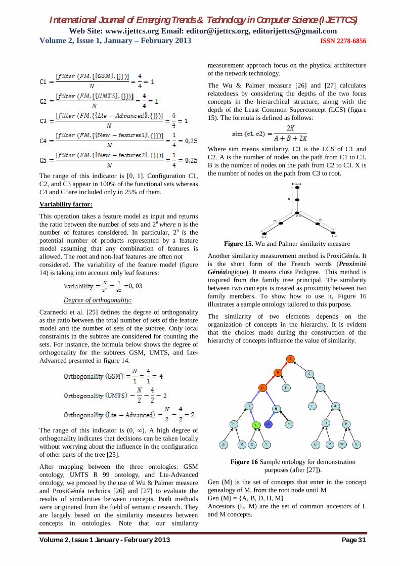
The range of this indicator is [0, 1]. Configuration C1, C2, and C3 appear in 100% of the functional sets whereas C4 and C5are included only in 25% of them.
Variability factor:
This operation takes a feature model as input and returns the ratio between the number of sets and 2n where n is the number of features considered. In particular, 2n is the potential number of products represented by a feature model assuming that any combination of features is allowed. The root and non-leaf features are often not considered. The variability of the feature model (figure 14) is taking into account only leaf features:
0, 03
Degree of orthogonality:
Czarnecki et al. [25] defines the degree of orthogonality as the ratio between the total number of sets of the feature model and the number of sets of the subtree. Only local constraints in the subtree are considered for counting the sets. For instance, the formula below shows the degree of orthogonality for the subtrees GSM, UMTS, and Lte-Advanced presented in figure 14.
The range of this indicator is (0, ∞). A high degree of orthogonality indicates that decisions can be taken locally without worrying about the influence in the configuration of other parts of the tree [25].
After mapping between the three ontologies: GSM ontology, UMTS R 99 ontology, and Lte-Advanced ontology, we proceed by the use of Wu & Palmer measure and ProxiGénéa technics [26] and [27] to evaluate the results of similarities between concepts. Both methods were originated from the field of semantic research. They are largely based on the similarity measures between concepts in ontologies. Note that our similarity
measurement approach focus on the physical architecture of the network technology.
The Wu & Palmer measure [26] and [27] calculates relatedness by considering the depths of the two focus concepts in the hierarchical structure, along with the depth of the Least Common Superconcept (LCS) (figure 15). The formula is defined as follows:
Where sim means similarity, C3 is the LCS of C1 and C2. A is the number of nodes on the path from C1 to C3. B is the number of nodes on the path from C2 to C3. X is the number of nodes on the path from C3 to root.
Figure 15. Wu and Palmer similarity measure
Another similarity measurement method is ProxiGénéa. It is the short form of the French words (Proximité Généalogique). It means close Pedigree. This method is inspired from the family tree principal. The similarity between two concepts is treated as proximity between two family members. To show how to use it, Figure 16 illustrates a sample ontology tailored to this purpose.
The similarity of two elements depends on the organization of concepts in the hierarchy. It is evident that the choices made during the construction of the hierarchy of concepts influence the value of similarity.
Figure 16 Sample ontology for demonstration
purposes (after [27]).
Gen (M) is the set of concepts that enter in the concept genealogy of M, from the root node until M Gen (M) = {A, B, D, H, M Ancestors (L, M) are the set of common ancestors of L and M concepts.

International Journal of Emerging Trends & Technology in Computer Science (IJETTCS) Web Site: www.ijettcs.org Email: [email protected], [email protected]
Volume 2, Issue 1, January – February 2013 ISSN 2278-6856
Volume 2, Issue 1 January - February 2013 Page 32
Ancestors (L, M) = Gen (L) ∩ Gen (M) = {A, B, D, G, L ∩ {A, B, D, H, M = {A, B, D
Sim (L, M) =
Sim (L, M)
The results of the similarities between network technology components, belonging to the physical part subject of table 1, are given in the following table 3. Charts (figure 17 and 18) describe the similarity measurements given by each method. Meanwhile, the chart subject of figure 19 illustrates the comparison between the two similarity measurements generated by the two different methods. It confirms the existence of some sort of similarities.
Table 3. Ontology Concepts Similarities’ measurements.
Measure Sim (.. ,.. ) Wu and
Palmer ProxiGénéa Aimed
Similarity (SIM, USIM) 1 0,75 1
(MS,ME) 0,33 0,57 1 (BSS,RNS) 0,64 0,80 1 (BTS, eNB) 1 1 1
(BSC, UTRAN) 1 1 1 (MSC, MSC) 1 1 1 (VLR, VLR) 1 1 1 (HLR, HSS) 0,38 0,77 1
(SGSN, SGW) 0,33 0,86 1 (GGSN, PGW) 0,38 0,77 1 (MSC, MME) 0,44 0,83 1
(CN, EPC) 0,8 0,67 1 (PSTN, PSTN) 1 1 1 (PDN, PDN) 1 1 1 (BSC, RNC) 0,53 0,73 1
(Eir, Eir) 1 1 1 (AuC, AuC) 1 1 1
(OMC, OMC) 1 1 1 (TRAU, TRAU) 1 1 1 (PCRF, PCRF) 1 1 1
Figure 17. Similarity measurement of the ontology
concepts’ with Wu and Palmer method.
Figure 28. Similarity measurement of the ontology concepts’ with ProxiGénéa method.
Figure 39. Comparison of the two methods’ results.
6. VALIDATION
Recall that the research hypothesis (presented in the introduction) call for determining the theoretical feasibility of using federation ontology to integrate the cellular communication network technologies. The overall approach to providing evidence confirming this hypothesis was to apply the ontology to three network technologies and then observe how the domain will be clear in unambiguous way. Throughout this tentative, just theoretical feasibility evidence is established. There are two main purposes behind that: First, the effort advocated to substantiate technical
feasibility of the federated ontology by actually integrating all existing cellular network technologies is a massive burden, require huge effort.
Second, the ontology is still in research phase or is considered as an area for future research.
7. CONCLUSION The organization mode of the unstructured and non-formal cellular communication networks knowledge is hampering its sharing. How to make this knowledge reused and be shared in order to achieve tangible understandability is still a challenging problem that the telecommunication and knowledge engineers have been facing. The way to address this problem (the lack of shared understanding, poor communication, and disparate modeling methods) is by reducing or eliminating conceptual and terminological confusion and coming to a shared understanding. Such shared understanding can function as a unifying framework for different viewpoints and serve as the basis for communication between people involved in the domain.

International Journal of Emerging Trends & Technology in Computer Science (IJETTCS) Web Site: www.ijettcs.org Email: [email protected], [email protected]
Volume 2, Issue 1, January – February 2013 ISSN 2278-6856
Volume 2, Issue 1 January - February 2013 Page 33
REFERENCES [1] David Cleary, Boris Danev, Diarmuid O'
Donoghue, “Using Ontologies to Simplify Wireless Network Configuration”; Formal Ontologies Meet Industry, Verona, Italy, June 9-10, 2005.
[2] Thomas R. Gruber, “Toward Principles for the Design of Ontologies Used for Knowledge Sharing”, International Journal Human-Computer Studies 43, p.907-928. Presented at the “International Workshop on Formal Ontology”, March, 1993, Padova, Italy.
[3] Neji HASNI. “Ontology for Cellular Communication”, Proceedings of Tunisian Japanese Symposium on “Science, Society and Technology,” November 11-13, 2011, Tunisia.
[4] Asma Alazeib, “An Ontology for Generic Wireless Authentication”, master theses, Stuttgart, 07.October.2005.
[5] Czarnecki, K. and Eisenecker, U., Generative Programming Methods,Tools, and Applications, Addison-Wesley, 2000.
[6] Neji HASNI. "Towards an interoperability ontology for software development tools" Master’s Thesis, Computer Science Department, Naval Postgraduate School, Monterey, CA, March 2003.
[7] Neji HASNI, Ridha BOUALLEGUE. “Ontology Based Interoperability Approach for Heterogeneous Mobile Cellular Networks”, International Journal of Computer Applications (0975 – 8887), September 25, 2012.
[8] Neji HASNI, Ridha BOUALLEGUE. “Roadmap for Establishing Interoperability of Heterogeneous Cellular Network Technologies -3-,” International Journal of Computer Applications, Vol. 54 No.5, pp 17-27, September 2012.
[9] 3GPP TS 23.401: “GPRS Enhancements for E-UTRAN Access”. Available at: http://www.ee.washington.edu/research/ieee-comm/event_nov_13_2008_files/IEEE%20-%20SAE%20and%20Enhanced%20Packet%20Core.pdf
[10] 3GPP TS 36.331: “Evolved Universal Terrestrial Radio Access (E-UTRA); Radio Resource Control (RRC); Protocol Specification”. Available: http://www.3gpp.org/ftp/Specs/htmlinfo/36331.htm.
[11] Universal Mobile Telecommunications System (UMTS); Radio Resource Control (RRC) protocol specification, (3GPP TS 25.331 version 6.8.0 Release 6), ETSI TS 125 331 V6.8.0. (2005-12).
[12] Kaveh, P. and Prashant, K.,” Principles of Wireless Networks, A Unified Approach”, ISBN 0-13-083003-2; Prentice Hall PTR; 2002.
[13] N. Hasni, R. Bouallegue, “Roadmap for Establishing Interoperability of Heterogeneous Cellular Network Technologies -2-”, Journal of
Signal and Information Processing, VOL.3 No.3, August 2012.
[14] Heikki Kaaranen et al, “UMTS Networks Architecture, Mobility and Services”, Second Edition, 2005.
[15] “Overview of 3GPP Release 99 Summary of all Release 99 Features” ETSI Mobile Competence Centre Version 05/03/04.
[16] Andreas Mitschele-Thiel, Jens Mückenheim, UMTS Networks, Oct-12. Available at: http://www.tu ilmenau.de/fileadmin/public/iks/files/lehre/UMTS/04_UMTS-architecture-ws12.pdf
[17] Erik Dahlman et al., “4G LTE/Lte-advanced for Mobile Broadband”, 1st edition, UK: Elsevier, 2011.
[18] A. Omri, R. Hamila, M. Hasna , R. Bouallegue and H. Chamkhia, “Estimation of highly selective channels for downlink LTE MIMO-OFDM system by a robust neural network”, Journal of Ubiquitous Systems and Pervasive NetworksVolume 2, No. 1 pp. 31-38, (2011).
[19] David Wong Tung Chong, “EE5406 Wireless Network Protocols –Network Architectures, http://www1.i2r.astar. edu.sg/~wongtc/course.html Academic Year 2010/2011.
[20] Fei Cao, et al., “Automating Feature-Oriented Domain Analysis”, Proc. of the “International Conference on Software Engineering Research and Practice (SERP'03)”, CSREA, 2003.
[21] Kwanwoo Lee, Kyo C. Kang, and Jaejoon Lee, “Concepts and Guidelines of Feature Modeling for Product Line Software Engineering”, Department of Computer Science and Engineering, Pohang University of Science and Technology, Korea.
[22] Geyer, L., “Feature Modeling Using Design Spaces,” Proceedings of the 1st German Workshop on Product Line Software Engineering, Kaiserslautern, Germany, November 2000.
[23] David Benavides, Sergio Segura and Antonio Ruiz-Cortés, “Automated Analysis of Feature Models 20 Years Later: A Literature Review”, Jornadas de Ingenier´ıa del Software y Bases de Datos (JISBD’06).
[24] D. Fernandez-Amoros, R. Heradio, and J. Cerrada. “Inferring information from feature diagrams to product line economic models”. In Proceedings of the Sofware Product Line Conference, 2009.
[25] K. Czarnecki and P. Kim. “Cardinality-based feature modeling and constraints: A progress report”. In Proceedings of the International Workshop on Software Factories At OOPSLA, 2005.
International Journal of Emerging Trends & Technology in Computer Science (IJETTCS) Web Site: www.ijettcs.org Email: [email protected], [email protected]
Volume 2, Issue 1, January – February 2013 ISSN 2278-6856
Volume 2, Issue 1 January - February 2013 Page 34
[26] Wu, Z., and Palmer, M.. “Verb semantics and lexical selection”. In 32nd Annual Meeting of the Association for Computational Linguistics, 1994, pp. 133-138.
[27] Bachelin RALALASON, “Représentation multi-facette des documents pour leur accès sémantique”, Ph.D theses in computer science, Computer Science Research Institute of Toulouse, France, septembre, 30, 2010.
[28] 3GPP TS 36.413: “Evolved Universal Terrestrial Radio Access Network (E-UTRAN); S1 Application Protocol (S1AP)”
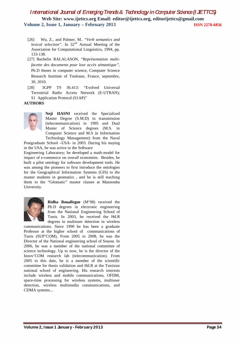
AUTHORS
Neji HASNI received the Specialized Master Degree (S.M.D) in transmission (telecommunication) in 1995 and Dual Master of Science degrees (M.S. in Computer Science and M.S in Information Technology Management) from the Naval
Postgraduate School –USA- in 2003. During his staying in the USA, he was active in the Software Engineering Laboratory; he developed a math-model for impact of e-commerce on overall economies. Besides, he built a pilot ontology for software development tools. He was among the pioneers to first introduce the ontologies for the Geographical Information Systems (GIS) to the master students in geomatics , and he is still teaching them to the “Géomatic” master classes at Mannouba University.
Ridha Bouallegue (M’98) received the Ph.D degrees in electronic engineering from the National Engineering School of Tunis. In 2003, he received the Hd.R degrees in multiuser detection in wireless
communications. Since 1990 he has been a graduate Professor at the higher school of communications of Tunis (SUP’COM), From 2005 to 2008, he was the Director of the National engineering school of Sousse. In 2006, he was a member of the national committee of science technology. Up to now, he is the director of the Innov’COM research lab (telecommunication). From 2005 to this date, he is a member of the scientific committee for thesis validation and Hd.R at the Tunisian national school of engineering. His research interests include wireless and mobile communications, OFDM, space-time processing for wireless systems, multiuser detection, wireless multimedia communications, and CDMA systems...