highly efficient cutter with a 66° cutting edge angle … · suppresses vibration for excellent...
TRANSCRIPT
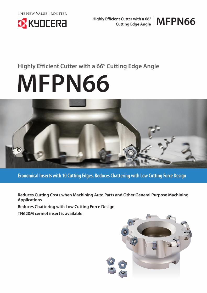
Reduces Cutting Costs when Machining Auto Parts and Other General Purpose Machining Applications
Reduces Chattering with Low Cutting Force Design
TN620M cermet insert is available
Economical Inserts with 10 Cutting Edges. Reduces Chattering with Low Cutting Force Design
Highly Efficient Cutter with a 66° Cutting Edge Angle
MFPN66
MFPN66Highly Efficient Cutter with a 66° Cutting Edge Angle
Economical Inserts with 10 Cutting EdgesApplicable to various machining applications with wide size range from ø32
Reduces Chattering with Low Cutting Force DesignFor Stainless Steel Machining
Cost reduction in various applications from general parts to automotive parts machining
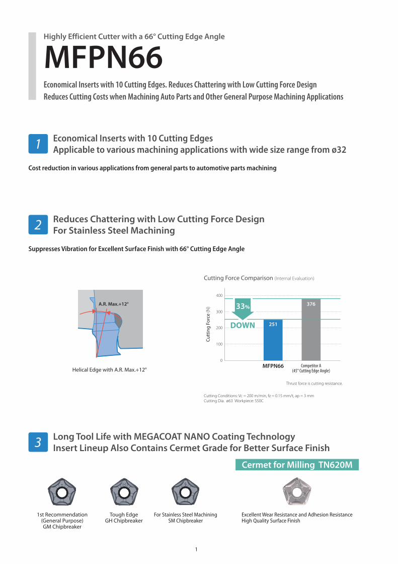
Suppresses Vibration for Excellent Surface Finish with 66° Cutting Edge Angle
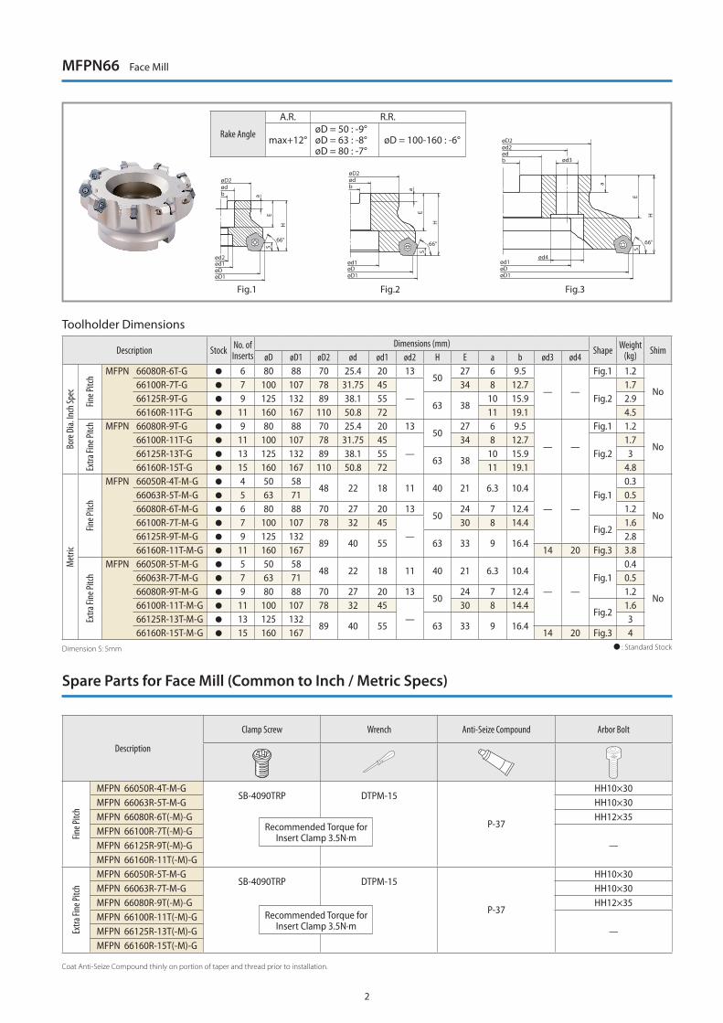
Long Tool Life with MEGACOAT NANO Coating TechnologyInsert Lineup Also Contains Cermet Grade for Better Surface Finish
Cutting Force Comparison (Internal Evaluation)
Cutting Conditions: Vc = 200 m/min, fz = 0.15 mm/t, ap = 3 mmCutting Dia. ø63 Workpiece: S50C
Thrust force is cutting resistance.
Tough EdgeGH Chipbreaker
1st Recommendation (General Purpose)GM Chipbreaker
For Stainless Steel MachiningSM Chipbreaker
A.R. Max.+12°
Helical Edge with A.R. Max.+12°
Excellent Wear Resistance and Adhesion ResistanceHigh Quality Surface Finish
Cermet for Milling TN620M
Economical Inserts with 10 Cutting Edges. Reduces Chattering with Low Cutting Force DesignReduces Cutting Costs when Machining Auto Parts and Other General Purpose Machining Applications
Highly Efficient Cutter with a 66° Cutting Edge Angle
MFPN66
1
2
3
1
Cutt
ing
Forc
e (N)
400
0
100
200
300
MFPN66 Competitor A(45° Cutting Edge Angle)
DOWN
33%
251
376
MFPN66 Face Mill
Toolholder Dimensions
Description Stock No. of Inserts
Dimensions (mm)Shape Weight
(kg) ShimøD øD1 øD2 ød ød1 ød2 H E a b ød3 ød4
Bore
Dia.
Inch
Spec
Fine P
itch MFPN 66080R-6T-G 6 80 88 70 25.4 20 13
5027 6 9.5
— —
Fig.1 1.2
No66100R-7T-G 7 100 107 78 31.75 45
—34 8 12.7
Fig.21.7
66125R-9T-G 9 125 132 89 38.1 5563 38
10 15.9 2.966160R-11T-G 11 160 167 110 50.8 72 11 19.1 4.5
Extra
Fine
Pitch MFPN 66080R-9T-G 9 80 88 70 25.4 20 13
5027 6 9.5
— —
Fig.1 1.2
No66100R-11T-G 11 100 107 78 31.75 45
—34 8 12.7
Fig.21.7
66125R-13T-G 13 125 132 89 38.1 5563 38
10 15.9 366160R-15T-G 15 160 167 110 50.8 72 11 19.1 4.8
Met
ric
Fine P
itch
MFPN 66050R-4T-M-G 4 50 5848 22 18 11 40 21 6.3 10.4
— —Fig.1
0.3
No
66063R-5T-M-G 5 63 71 0.566080R-6T-M-G 6 80 88 70 27 20 13
5024 7 12.4 1.2
66100R-7T-M-G 7 100 107 78 32 45—
30 8 14.4Fig.2
1.666125R-9T-M-G 9 125 132
89 40 55 63 33 9 16.42.8
66160R-11T-M-G 11 160 167 14 20 Fig.3 3.8
Extra
Fine
Pitch
MFPN 66050R-5T-M-G 5 50 5848 22 18 11 40 21 6.3 10.4
— —Fig.1
0.4
No
66063R-7T-M-G 7 63 71 0.566080R-9T-M-G 9 80 88 70 27 20 13
5024 7 12.4 1.2
66100R-11T-M-G 11 100 107 78 32 45—
30 8 14.4Fig.2
1.666125R-13T-M-G 13 125 132
89 40 55 63 33 9 16.43
66160R-15T-M-G 15 160 167 14 20 Fig.3 4 : Standard Stock
Rake Angle
A.R. R.R.
max+12°øD = 50 : -9°øD = 63 : -8°øD = 80 : -7°
øD = 100-160 : -6°
Spare Parts for Face Mill (Common to Inch / Metric Specs)
Description
Clamp Screw Wrench Anti-Seize Compound Arbor Bolt
Fine P
itch
MFPN 66050R-4T-M-GSB-4090TRP DTPM-15
P-37
HH10×30MFPN 66063R-5T-M-G HH10×30MFPN 66080R-6T(-M)-G HH12×35MFPN 66100R-7T(-M)-G
—MFPN 66125R-9T(-M)-GMFPN 66160R-11T(-M)-G
Extra
Fine
Pitch
MFPN 66050R-5T-M-GSB-4090TRP DTPM-15
P-37
HH10×30MFPN 66063R-7T-M-G HH10×30MFPN 66080R-9T(-M)-G HH12×35MFPN 66100R-11T(-M)-G
—MFPN 66125R-13T(-M)-GMFPN 66160R-15T(-M)-G
Recommended Torque for Insert Clamp 3.5N·m
Recommended Torque for Insert Clamp 3.5N·m
Coat Anti-Seize Compound thinly on portion of taper and thread prior to installation.
Dimension S: 5mm
2
ød2ød1øDøD1
øD2ødb
ød1øDøD1
øD2ødb
a
E
H
S 66°66°
a
E
H
S
ød1ød4
øDøD1
øD2ød2
ød3ødb
66°
a
E
H
S
Fig.1 Fig.2 Fig.3
3
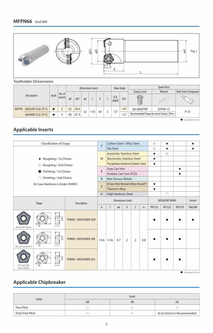
Toolholder Dimensions
Description Stock No. of Inserts
Dimensions (mm) Rake Angle Spare PartsClamp Screw Wrench Anti-Seize Compound
øD øD1 ød L ℓ S A.R.(MAX) R.R
MFPN 66032R-S32-2T-G 2 32 39.532 110 30 5 12°
-14° SB-4090TRP DTPM-15P-37
66040R-S32-3T-G 3 40 47.5 -12° : Standard Stock
Recommended Torque for Insert Clamp 3.5N·m
MFPN66 End Mill
Applicable Chipbreaker
CutterInsert
GM SM GH
Fine Pitch
Extra Fine Pitch fz=0.2mm/t is Recommended
Classification of UsageP
Carbon Steel / Alloy Steel
: Roughing / 1st Choice
: Roughing / 2nd Choice
: Finishing / 1st Choice
: Finishing / 2nd Choice
(In Case Hardness is Under 45HRC)
Die Steel
M
Austenitic Stainless Steel
Martensitic Stainless Steel
Precipitation Hardened Stainless Steel
KGray Cast Iron
Nodular Cast Iron (FCD)
N Non Ferrous Metals
SNi-base Heat-Resistant Alloys (Inconel®)
Titanium Alloy
H High Hardness Steel
Shape DescriptionDimensions (mm) MEGACOAT NANO Cermet
A T ød X Z rε PR1535 PR1525 PR1510 TN620M
GM General Purpose
A
T
Z
X
ød PNMU 0905XNER-GM
14.6 5.56 4.7 2 2 0.8
SM Low Cutting Force
A
T
Z
X
ød PNMU 0905XNER-SM
GH Tough Edge(Heavy Milling)
A
T
Z
X
ød PNMU 0905XNER-GH
: Standard Stock
Applicable Inserts
øD1
øD ød
Sℓ
L
66°
Fig.1
4
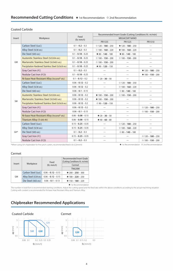
Recommended Cutting Conditions 1st Recommendation 2nd Recommendation
Insert Workpiece Feed(fz: mm/t)
Recommended Insert Grade (Cutting Conditions Vc: m/min) MEGACOAT NANO
PR1535 PR1525 PR1510
GM
Carbon Steel (SxxC) 0.1 – 0.2 – 0.3 120 – 180 – 250 120 – 180 – 250 —
Alloy Steel (SCM etc) 0.1 – 0.2 – 0.3 100 – 160 – 220 100 – 160 – 220 —
Die Steel (SKD etc) 0.1 – 0.18 – 0.25 80 – 140 – 180 80 – 140 – 180 —
Austenitic Stainless Steel (SUS304 etc) 0.1 – 0.18 – 0.25 100 – 150 – 200 100 – 150 – 200 —
Martensitic Stainless Steel (SUS403 etc) 0.1 – 0.18 – 0.25 100 – 150 – 200 — —
Precipitation Hardened Stainless Steel (SUS630 etc) 0.1 – 0.18 – 0.25 90 – 120 – 150 — —
Gray Cast Iron (FC) 0.1 – 0.2 – 0.3 — — 120 – 180 – 250
Nodular Cast Iron (FCD) 0.1 – 0.18 – 0.25 — — 100 – 150 – 200
Ni-base Heat-Resistant Alloy (Inconel® etc) 0.1 – 0.12 – 0.2 20 – 30 – 50 — —
SM
Carbon Steel (SxxC) 0.06 – 0.12 – 0.2 — 120 – 180 – 250 —
Alloy Steel (SCM etc) 0.06 – 0.12 – 0.2 — 100 – 160 – 220 —
Die Steel (SKD etc) 0.06 – 0.1 – 0.15 — 80 – 140 – 180 —
Austenitic Stainless Steel (SUS304 etc) 0.06 – 0.12 – 0.2 100 – 150 – 200 100 – 150 – 200 —
Martensitic Stainless Steel (SUS403 etc) 0.06 – 0.12 – 0.2 100 – 150 – 200 — —
Precipitation Hardened Stainless Steel (SUS630 etc) 0.06 – 0.12 – 0.2 90 – 120 – 150 — —
Gray Cast Iron (FC) 0.06 – 0.12 – 0.2 — — 120 – 180 – 250
Nodular Cast Iron (FCD) 0.06 – 0.1 – 0.15 — — 100 – 150 – 200
Ni-base Heat-Resistant Alloy (Inconel® etc) 0.06 – 0.08 – 0.15 20 – 30 – 50 — —
Titanium Alloy (Ti-6Al-4V) 0.06 – 0.08 – 0.15 40 – 60 – 80 — —
GH*
Carbon Steel (SxxC) 0.15 – 0.25 – 0.35 — 120 – 180 – 250 —
Alloy Steel (SCM etc) 0.15 – 0.25 – 0.35 — 100 – 160 – 220 —
Die Steel (SKD etc) 0.1 – 0.2 – 0.3 — 80 – 140 – 180 —
Gray Cast Iron (FC) 0.15 – 0.25 – 0.35 — — 120 – 180 – 250
Nodular Cast Iron (FCD) 0.1 – 0.2 – 0.3 — — 100 – 150 – 200
1st Recommendation 2nd Recommendation
The number in bold font is recommended starting conditions. Adjust the cutting speed and the feed rate within the above conditions according to the actual machining situationCutting with coolant is recommended for Ni-base Heat Resistant Alloy and Titanium Alloy.
*When using GH chipbreaker for fine pitch cutters, recommended feed is fz 0.2(mm/t)
Coated Carbide
Cermet
Coated Carbide Cermet
Insert Workpiece Feed(fz: mm/t)
Recommended Insert Grade (Cutting Conditions Vc: m/min)
CermetTN620M
GM
Carbon Steel (SxxC) 0.06 – 0.12 – 0.15 200 – 250 – 300
Alloy Steel (SCM etc) 0.06 – 0.12 – 0.15 180 – 220 – 250
Die Steel (SKD etc) 0.06 – 0.1 – 0.13 150 – 180 – 220
1st Recommendation
Chipbreaker Recommended Applications
ap (m
m)
fz (mm/t)
5
3
0.5
0.1 0.2 0.30.25 0.350.06
SM
GH
GM
ap (m
m)
fz (mm/t)
5
3
2
0.5
0.06 0.1 0.15 0.2 0.3
GM
© 2017 KYOCERA Corporation CP407
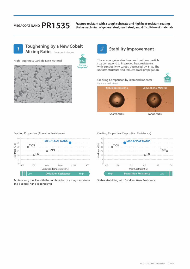
Fracture resistant with a tough substrate and high heat-resistant coatingStable machining of general steel, mold steel, and difficult-to-cut materialsMEGACOAT NANO PR1535
Toughening by a New Cobalt Mixing Ratio Stability Improvement1 2
23%
FractureToughness*
UP*In-house Evaluation
High Toughness Carbide Base Material
ShockResistance
UP
The coarse grain structure and uniform particle size correspond to improved heat resistance, with conductivity values decreased by 11%. The uniform structure also reduces crack propagation.
Cracking Comparison by Diamond Indenter(In-house evaluation)
PR1535 Base Material Conventional Material
Short Cracks Long Cracks
Oxidation Resistance
40
35
30
25
20
15
10400 600 800 1,000 1,200 1,400
Low High
TiCN
TiNTiAIN
MEGACOAT NANO
Har
dnes
s (G
Pa)
Oxidation Temperature (°C)
40
35
30
25
20
15
100.3 0.4 0.5 0.6 0.7 0.8
Deposition ResistanceHigh Low
TiCN
TiN
TiAIN
MEGACOAT NANO
Har
dnes
s (G
Pa)
Wear Coe�cient (μ)
Coating Properties (Abrasion Resistance) Coating Properties (Deposition Resistance)
Achieve long tool life with the combination of a tough substrate and a special Nano coating layer
Stable Machining with Excellent Wear Resistance