high‐temperature solar selective coating development … 5... · · 2016-08-12csp program...
TRANSCRIPT

energy.gov/sunshot energy.gov/sunshot CSP Program Summit 2016
energy.gov/sunshot energy.gov/sunshot energy.gov/sunshot
CSP Program Summit 2016
High‐Temperature Solar Selective Coating Development for Power Tower Receivers
CSP: LDPD_Ambrosini_A Duration: 3 years (ending Dec. 2015) DOE Funding: $2,517,000
Andrea Ambrosini, Sandia National Laboratories

energy.gov/sunshot energy.gov/sunshot CSP Program Summit 2016 2
Team and Acknowledgments
Clifford Ho Aaron Hall Timothy Lambert Antoine Boubault John Lewis Lam Banh James Pacheco Cheryl Ghanbari David Adams David Saiz Danae Davis Andrew Hunt Marlene Knight Bonnie McKenzie Landon Davis Pylin Sarobol
Matthew Gray (co‐PI) Robert Tirawat Paul Ndione Cheryl Kennedy Kaan Korkmaz Ross Larsen Vincent Wheeler Tim Wendelin Katelyn Kessinger Brian Gorman Michele Olsen Marlene Bencomo Judy Netter Greg Glatzmaier Brian Li
Sandia National Laboratories is a multi-program laboratory managed and operated by Sandia Corporation, a wholly owned subsidiary of Lockheed Martin Corporation, for the U.S. Department of Energy’s National Nuclear
Security Administration under contract DE-AC04-94AL85000. SAND Number: 2014-3715P.

energy.gov/sunshot energy.gov/sunshot CSP Program Summit 2016 3
Problem Statement
To meet the SunShot goal of Levelized cost of energy (LCOE) ≤ 6¢/kWh by 2020, next generation power towers will operate at temperatures > 600 °C in order to take advantage of increased efficiencies of high-temperature operation. Current receiver coatings, such as Pyromark 2500, while highly absorptant, suffer from high emittance and have been reported to degrade during operation at T > 600 °C . Advanced solar selective absorber (SSA) coatings are required that have a solar efficiency, η, surpassing that of Pyromark® 2500, are stable at ≥ 600 ºC in air, have high thermal conductivity, and are nonvolatile.
00.10.20.30.40.50.60.70.80.9
1
0 1 2 3 4 5 6 7 8 9 101112131415Nor
mal
ized
Ene
rgy/
Abs
orpt
ance
Wavelength (μm)
Selective Absorption Spectra
ASTM G173 DNIBlack Body (700C)Ideal absorber Pyromark (est’d)
energy.gov/sunshot energy.gov/sunshot CSP Program Summit 2016 4
Value Proposition
Formulations of mixed-metal oxides, such as spinels (AB2O4) and perovskites (ABO3), are promising candidates for next-gen receiver coatings. They are stable at high-temperatures, oxidation resistant, can be easily deposited via techniques such as thermal spray, and are amenable to cation doping and substitution to chemically tailor their properties. Refractory metal silicides (MSix) are another class of materials that display inherently high absorptance and low emittance in multilayer SSA coatings. Both families are reported herein.
An increase in the thermal efficiency of SSZ coatings by 4% at 650 °C, and 7% at 800 °C, can potentially reduce the LCOE by an
estimated 0.25 ¢/kWh.

energy.gov/sunshot energy.gov/sunshot CSP Program Summit 2016 5
Deposition Methods
Spin Coating
Facile synthesis of coatings with varying
formulations and dopant concentrations
Allows for rapid deposition and optical
screening of a composition space
Electrodeposition
Novel approach to screening solar
selective materials
Can result in unusual surface morphologies
Thermal Spray
High-surface area coating technique
Ability to coat in the field
Can modify surface morphology in an efficient and cost-effective manner
Physical Vapor Deposition
Fine control of deposition conditions
Control of optical, microstructural, &
mechanical properties
Pulsed DC sputtering is commercial method
used for receiver tubes
A complimentary suite of coating techniques to investigate novel formulations, surface morphology, layered structures and scale-up.

energy.gov/sunshot energy.gov/sunshot CSP Program Summit 2016 6
Deposition Methods
Spin Coating
Facile synthesis of coatings with varying
formulations and dopant concentrations
Allows for rapid deposition and optical
screening of a composition space
Electrodeposition
Novel approach to screening solar
selective materials
Can result in unusual surface morphologies
Thermal Spray
High-surface area coating technique
Ability to coat in the field
Can modify surface morphology in an efficient and cost-effective manner
Physical Vapor Deposition
Fine control of deposition conditions
Control of optical, microstructural, &
mechanical properties
Pulsed DC sputtering is commercial method
used for receiver tubes
A complimentary suite of coating techniques to investigate novel formulations, surface morphology, layered structures and scale-up.
energy.gov/sunshot energy.gov/sunshot CSP Program Summit 2016 7 CSP Program Summit 2016
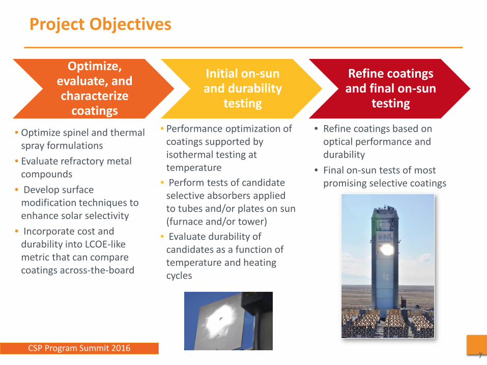
• Optimize spinel and thermal spray formulations
• Evaluate refractory metal compounds
• Develop surface modification techniques to enhance solar selectivity
• Incorporate cost and durability into LCOE-like metric that can compare coatings across-the-board
Project Objectives
7
Optimize, evaluate, and characterize
coatings
Initial on‐sun and durability
testing
Refine coatings and final on‐sun
testing
• Performance optimization of coatings supported by isothermal testing at temperature
• Perform tests of candidate selective absorbers applied to tubes and/or plates on sun (furnace and/or tower)
• Evaluate durability of candidates as a function of temperature and heating cycles
• Refine coatings based on optical performance and durability
• Final on-sun tests of most promising selective coatings

energy.gov/sunshot energy.gov/sunshot CSP Program Summit 2016 8
Milestones ‐ Sandia
MS Description % Complete
1.1 Quantify parameters (doping concentrations, thickness, deposition methods, substrate choice, and synthesis conditions) which yield optimized solar selective properties for spinels and thermally sprayed coating and meet or exceed the selective absorber efficiency of best formulations from FY12 AOP (e.g., Co3O4-based spinels,ηsel=0.916) and present to DOE statistical method used and results.
100%
1.3 Complete SAND report documenting the system-level metric for candidate selective surface coating and Pyromark which incorporates initial and reoccurring costs (materials, labor, and equipment) along with performance. 100%
2.1.1 Determine acceptable material performance based on selective absorber efficiency vs. degradation rate for a given reapplication interval. 100%
2.1.2 Identify at least one successful candidate coating. A successful coating will exhibit a calculated LCOC less than that of Pyromark, which is currently estimated at $0.055/MWht. 75%
2.2.1 Utilize results of Gibbs free energy modeling to predict potential secondary phase reaction between substrates and coatings. Apply results to identification of by-products during heating tests, and determine if the model effectively predicts phase formation (within 80%), thus allowing us to assess the effectiveness of such calculations as a tool for predicting substrate-coating interaction.
0%
2.2.2 Produce at least one coating with a solar selective efficiency of ηsel > 0.911 under similar conditions. 95%
2.2.3 Utilize isothermal measurements calculate degradation rates of the coatings. From these data, reapplication intervals and performance can be estimated. Candidate materials that fall within the shaded region of Fig. 1 will be considered promising. 90%
2.2.4 Evaluate mechanical durability of coatings after high temperature exposure using an appropriate adhesion test method. 50%
2.2.5 Utilize characterization results to identify types and possible causes of performance degradation in coatings. Depending on the type and extent of the degradation, solutions such as applying a barrier coating to resist cation diffusion or an AR top layer to prevent surface sintering can be investigated as remediation techniques.
90%
2.3.1 Build and test the on-sun test rig. Validate its performance by running a test matrix on Pyromark 2500 and comparing it with previous data taken on the Pyromark material to see if the results track to within 90% with previously published observations of Pyromark performance. 100%
2.3.2
Document performance (absorbed power, efficiency, durability) and characterization (optical and structural) of candidate coatings under solar conditions representative of CSP receiver operating conditions, (e.g., thermal conditions representing >500 kW/m2, ≥700°C, on-sun/off-sun cycling). Utilize data to further elucidate degradation processes identified in Task 2.2 and to identify coatings that meet acceptable metrics identified by the LCOC
100%
2.3.3 Identify candidate coatings that exhibit less degradation on-sun than Pyromark 2500, which is currently reported to optically degrade at 0.5 %/yr and require a reapplication interval of 5 years 80%
3.1.0 Populate Milestone Table file “SNL_Ambrosini_Correlation Coefficients” with all those variables that could be of interest in the Phase 3 experiments. Next, we will compute the number of combinations for all the variables in the file. Finally, we will state what subset of these combinations will be evaluated in Phase 3.
100%
3.1.1 Parameters most influential to coating performance (η) of Pyromark are identified 100% 3.2.1 Identify deposition parameters that maximize η after testing (>200 cycle at >700 °C ) 75% 3.3.1 Results from lab to field successfully translated 0% 3.3.2 Performance of coatings on Haynes tubes 20% 3.3.3 Disseminate results 0%

energy.gov/sunshot energy.gov/sunshot CSP Program Summit 2016 9
Milestones ‐ NREL
MS Description Complete
1.2.1 Downselect 5 candidate binary materials for full stack −−
1.2 Preliminary Rank-order of materials and methods for refrectory metal compounds based on η(sel) and thermal stability −−
2.1 Use plots of FOM vs roughness to determine range of adequate (>0.91) performance
2.2 Determine full rankings of tested single layer materials and applied coating designs for refractory metal compounds based on their ability to produce efficiency better than ηsel = 0.910 and degradation of < 1%/yr
2.3 Provide a rank ordering of the degradation rate of candidate samples at elevated temperatures in air as a function of hours of exposure. Identify at least two different base material coatings better than ηsel =0.910 after 400 hours of isothermal testing at 700 °C
--
2.4 Demonstrate control of intensity and temperature. Quantify performance, including uncertainties, for absorbed power, efficiency, and durability of candidate coatings under solar conditions representative of operating conditions (e.g., thermal conditions representing =500 kW/m2, =700 °C)
2.5 Quantify spectral reflectance and resulting ηsel for coatings at selected temperatures as a function of time (e.g., 0, 100, 300 hours) and cycles (e.g., 0, 10, 100 cycles). Demonstrate at least one coating where ηsel after cycling is greater than 0.910 after a minimum of 50 cycles at 700 °C.
--
3.1.1 We will exhaustively populate Milestone Table file “NREL_Gray_Correlation Coefficients” with all those variables that could be of interest in the Phase 3 experiments. Next, we will compute the number of combinations for all the variables in the file.
3.1.2 Embed the MS Word file “NREL_Gray_Correlation_Coefficients” containing the agreed to subset from milestone 3.1.1
3.1.3 Comparison of absorptance spectrum (250 -1700 nm) for un-aged and 500 hour aged, simplified multi-layer samples (3 or more layers including each of the materials (TaSi2, SiO2 and TiO2) used in the full SSA design).
3.1.4 Comparison of absorptance spectrum (250 -1700 nm) for un-aged, simplified multi-layer samples (3 or more layers including each of the materials (TaSi2, SiO2 and TiO2) used in the full SSA design) vs. modeled. --
3.1.5 Comparison of absorptance spectrum (250 -1700 nm) for 500 hour aged, simplified multi- layer samples (3 or more layers including each of the materials (TaSi2, SiO2 and TiO2) used in the full SSA design)vs. modeled.
3.1.6 Perform sensitivity analysis of material and/or layer impact on stack performance with variation in n, k and/or layer thickness according to observed bounds. Generate a hierarchy of influence. Focus initial efforts of establishing Correlation Coefficients (above) for primary influences.
−−

energy.gov/sunshot energy.gov/sunshot CSP Program Summit 2016 10
Levelized Cost of Coating (LCOC)
Solar efficiency, η, evaluates the optical properties of a material, which impacts the thermal energy absorbed. LCOC also incorporates degradation rate, material costs,
and reapplication costs resulting in a more comprehensive cost estimate.
Cannual = Total annualized coating costs = Initial coating cost/life of plant + Recoating costs/ recoating interval + Cost of additional (or fewer) heliostats to yield baseline power Ethermal = Annual thermal energy absorbed (new) – Lost energy absorbed due to degradation – Lost energy absorbed due to recoating down time (annualized)
LCOCmarginal = Cannual/Ethermal
αs = solar absorptance Q = irradiance on the receiver ε = thermal emittance σ = Stefan-Boltzmann constant T = surface temperature (K)
Solar Efficiency, η 4
ssel
Q TQ
α εση −=
• Assumed 100 MWe molten-salt power plant with a ~50% capacity factor • ηsel = 0.89 (solar absorptance = 0.96, thermal emittance = 0.87) • Assumed degradation rate of 0.5% per year
o Degradation rates and costs for materials, application, and reapplication are based on available data from Solar One, Ho et al. (2012), and eSolar
$0.008
$0.047
Annualized LCOC for Pyromark 2500 is $0.055/MWhth
Initial Materials and Application ($/MWh/y) Re-Application ($/MWh/y)

energy.gov/sunshot energy.gov/sunshot CSP Program Summit 2016
Solar Testing Facilities
SNL: Solar furnace test stand • Spot size: 6 inches • Peak irradiance: 6 MW m−2
• Average irradiance: 5 MW m−2 • Operational hours/day: 6 • Air cooled
NREL: Solar furnace test stand • Simultaneous measurement of multiple samples • Uniform illumination of samples • Minimal “cross-talk” between samples • T ~700 °C at 500 kW/m2
• Delivers 650 kW/m2 over 4”x4” area
SNL: Solar simulator • Spot size: 1 inch • Peak Irradiance:1.3 MW/m2
• Average Irradiance: 0.9 MW/m2
• Operational: 24/7 • Automatic, robotic sample holder
for multiple sample testing

energy.gov/sunshot energy.gov/sunshot CSP Program Summit 2016 12
Deposition Methods
Spin Coating
Facile synthesis of coatings with varying
formulations and dopant concentrations
Allows for rapid deposition and optical
screening of a composition space
Electrodeposition
Novel approach to screening solar
selective materials
Can result in unusual surface morphologies
Thermal Spray
High-surface area coating technique
Ability to coat in the field
Can modify surface morphology in an efficient and cost-effective manner
Physical Vapor Deposition
Fine control of deposition conditions
Control of optical, microstructural, &
mechanical properties
Pulsed DC sputtering is commercial method
used for receiver tubes
A complimentary suite of coating techniques to investigate novel formulations, surface morphology, layered structures and scale-up.

energy.gov/sunshot energy.gov/sunshot CSP Program Summit 2016
0
20
40
60
80
100
0.25 2.5 25
Refle
ctan
ce (%
)
Wavelength (μm)
TaSi2 –Optimized Single Layer
As Deposited
Annealed 1000°C
13
TaSi2‐Based Solar Selective Absorber
• TaSi2 material properties from previous modeling activities indicated potential application for multilayer SSA
• Crystallization of monolayer TaSi2 further improved optical properties o Increased IR reflectance (low
emittance) o Increased absorption in UV-Vis-
NIR o αs >0.94 and ηsol >0.91
• Stack design optimized for material and operating conditions

energy.gov/sunshot energy.gov/sunshot CSP Program Summit 2016 14
Selective Absorber Efficiency
Design/Material “9” Pyromark Solar Absorptance (%) 0.945 0.962
ε700 0.373 0.847 Irradiance (W/cm2) ηabs (700 °C)
10 0.755 0.532 20 0.850 0.747 30 0.882 0.819 40 0.897 0.854 50 0.907 0.876 60 0.913 0.890 70 0.918 0.901 80 0.921 0.908 90 0.924 0.914
100 0.926 0.919
0.0
0.2
0.4
0.6
0.8
1.0
0.1 1.0 10.0Wavelength (µm)
Solar Irradiance Blackbody Radiation SSA Reflectance
• TaSi2 SSA shows better efficiency than Pyromark across full irradiance spectrum at 700 °C
• LCOC shows benefit with annual degradation rates < 0.0075 η / yr

energy.gov/sunshot energy.gov/sunshot CSP Program Summit 2016 15
Barrier Layers
• Diffusion of substrate cations prevents single phase crystallization of TaSi2
o Ni compounds formed instead
• 1 µm barrier layer of Al2O3 allows for TaSi2 crystallization
• Optical performance with barrier layers matches stack performance on Si

energy.gov/sunshot energy.gov/sunshot CSP Program Summit 2016 16
Changes in Tantalum Silicide After Exposure (300 h)
• TaSi2 is stable < 500 °C in air • Material changes observed at higher
temperatures, resulting in decreased α, η • TaSi2 base layer appears to be oxidizing

energy.gov/sunshot energy.gov/sunshot CSP Program Summit 2016 17
Deposition Methods
Spin Coating
Facile synthesis of coatings with varying
formulations and dopant concentrations
Allows for rapid deposition and optical
screening of a composition space
Electrodeposition
Novel approach to screening solar
selective materials
Can result in unusual surface morphologies
Thermal Spray
High-surface area coating technique
Ability to coat in the field
Can modify surface morphology in an efficient and cost-effective manner
Physical Vapor Deposition
Fine control of deposition conditions
Control of optical, microstructural, &
mechanical properties
Pulsed DC sputtering is commercial method
used for receiver tubes
A complimentary suite of coating techniques to investigate novel formulations, surface morphology, layered structures and scale-up.

energy.gov/sunshot energy.gov/sunshot CSP Program Summit 2016 18
Thermal Spray Coatings & Laser‐Treatment
Laser-treatment of a thermal spray coating is a practical pathway for manufacturing a highly efficient, ceramic surface on a CSP receiver.
Thermal Spray: • Commercially available equipment & materials • Low cost application, suitable for large components • Proven technology in high temperature, high thermal
cycle applications (gas turbines) Laser‐treatment: • Raster laser beam over coating surface • Surface ablation not melting • Portable, straightforward process • Largely independent of thermal spray process • Potential to “refresh” a coating in-situ
Spray coated boiler tubes www.asbindustries.com
On site Coating of a coal boiler waterwall www.thefabricator.com

energy.gov/sunshot energy.gov/sunshot CSP Program Summit 2016 19
Thermal Spray LSM Perovskite
70
75
80
85
90
95
100
0 500 1000 1500 2000 2500
Abso
rban
ce (%
)
Wavelength (nm)
Laser TreatedAs-Sprayed
Diffuse reflectance of TS coating before and after laser treatment
Novel laser treatment of surface improves optical properties without changing composition or phase of coating (Patent pending)
LSM sample after laser-treatment
Sample α (sol) ε (80C rel) Efficiency, η LSM #1 As‐Sprayed 0.893 0.857 0.821 LSM #1 Laser‐Treated 0.958 0.898 0.892

energy.gov/sunshot energy.gov/sunshot CSP Program Summit 2016 20
Isothermal Aging (700 °C, 480 h)
• Slight degradation in optical properties after 700 °C/ 480 h (little to none at 600 °C)
• Little change in XRD or diffuse reflectance upon aging
• With the current (estimated) cost assumptions and performance data, there is a ~10% chance that LSM will yield a marginal LCOC less than the baseline LCOC of Pyromark 2500
0.850
0.870
0.890
0.910
0.930
0.950
0 100 200 300 400 500
ηsel
Time Aged (hours)
Isothermal 700 °C Inconel
LSM-I
Pyromark
0
500
1000
1500
Inte
nsity
(Cou
nts)
01-072-8067> (La 0.82Sr0.17)MnO3.021 - Lanthanum Strontium Manganese Oxide
20 30 40 50 60 70Two-Theta (deg)
480 hrs 240 hrs 12 hrs 0 hrs
0
0.1
0.2
0.3
0.4
0.5
0.6
0.7
0.8
0.9
1
-0.5 0 0.5 1 1.5 2 2.5
Cum
ulat
ive
Prob
abili
ty
Marginal LCOC ($/MWht)
Baseline LCOC withPyromark 2500
LSM Marginal LCOC
Co3O4 Marginal LCOC
Base
line
LCO
C w
ith P
yrom
ark
2500
($0.
055/
MW
ht)

energy.gov/sunshot energy.gov/sunshot CSP Program Summit 2016 21
LSM Surface Morphology
Laser-treated coatings maintain microstructure after isothermal aging
As-Sprayed Laser Treated Laser-Treated & Aged 700C/ 480 h

energy.gov/sunshot energy.gov/sunshot CSP Program Summit 2016 22
On‐sun Testing LSM/Inconel 625
0
200
400
600
800
1000
0
200
400
600
800
1000
0 50 100 150 200 250 300 350 400 450
Irrad
ianc
e (k
W.m
−2)
Tem
pera
ture
(°C
)
Time-aged (s)
Front temperatureIrradiance
Heating Profile: Automatic controlled forced convective cooling (200 W m−2 K−1)
0.9000.9100.9200.9300.9400.9500.9600.9700.9800.9901.000
0 50 100 150
Sola
r abs
orpt
ance
Number of cycles
LSM
Pyromark
600 kW m−2 - 0 kW m−2 / 700˚C - 100˚C
LSM ηfinal = 0.902 Pyromark ηfinal = 0.893

23 CSP Program Summit 2016
Pyromark
• Analyses point toward the following optimized deposition parameters to maximize likelihood of intact coatings with most favorable η:
– Grit blasted (rough) substrate surface – Small paint thickness (25 – 30 μm) – Slow curing rate (5 °C/min) – Curing temperature near 650 °C
• However, when exposed to rapid cycling at 600 kW/m2 / 700 °C on solar simulator, coating properties degrade quickly; results are preliminary and the mechanism of degradation has not yet been determined (bottom right)
0.75
0.80
0.85
0.90
0.95
1.00
C05
C16
C21
C23
C24
C33
C39
C41
C42
C48
A35
A92
P40
P45
Abso
rpta
nce
Before Cycling After Cycling
• Deposition parameters of Pyromark 2500 were investigated in order to identify factors that contribute most to coating performance
• Design of Experiment executed; many of the coatings delaminated during curing (top right) • Coatings that survive the curing process generally survive isothermal aging at 700 °C / 96 h
with no change in optical properties
energy.gov/sunshot energy.gov/sunshot CSP Program Summit 2016 24
Summary
NREL • TaSi2-based multilayer stack shows promise for SSA applications • Stack efficiency as designed exceeds that of Pyromark • Stack Design is air stable to T <500 °C • 1 µm Al2O3 barrier mitigates substrate interference of TaSi2 crystallization • Material changes of base layer observed at T>600 °C in air • High flux solar furnace stage developed for measurement and testing of on-sun
receiver material efficiency SNL • Thermal-sprayed LSM that was surface modified using a laser treatment shows
improved absorptivity • Coatings show no sign of degradation and little, if any, degradation in
absorptance after Isothermally aging at 600 and 700 °C/480 h • Preliminary on-sun tests at 700 °C also show good performance vs. Pyromark • High emissivity of the coatings remains a challenge

energy.gov/sunshot energy.gov/sunshot CSP Program Summit 2016
Path to Market
• Protecting the financial investments of potential commercial partners is considered critical, hence IP protection through the patent process is a priority. Filings to date include: o Aaron C. Hall and David P. Adams, "High Durability Solar Absorptive
Coating and Methods for Making Same.“ Filed 26-Feb-15, Appl. #14/632,838 (SNL)
o C. E. Kennedy “High Temperature Solar Selective Coatings,” Patent # 8893711, Awarded 11/25/2014. (NREL)
• Partner with key players through CRADA and FOAs (e.g. SBV, TCF) to maximize deployment opportunity
• Develop techno-economic analysis to accurately determine the effect of integrating new SSA coatings into a CSP plant
• Encourage stakeholders to utilize LCOC tool to evaluate costs of various SSA coatings throughout industry using a common metric

energy.gov/sunshot energy.gov/sunshot CSP Program Summit 2016 energy.gov/sunshot energy.gov/sunshot 26 26
Thank You