highway eng. earthworks & mass haul diagram 14...
TRANSCRIPT

Lecture 09 102
Highway Eng. Earthworks & Mass Haul Diagram 14 –15
Dr. Firas Asad
In this lecture;
---------------------
A- Roadwork equipments
B- Earthworks quantities
C- Mass Haul Diagram
Ground elevation
Grade
Side slope
Fill
Cut Grade
Highway Earthworks and Mass Haul Diagram
The information listed in this lecture is mainly taken from; the Iraqi General Specifications for Roads and Bridge (SCRB, 2007), Traffic and Highway Engineering (Garber and Hoel, 2009) and Highways (O’Flaherty, 2007).
A- Highway Grades and Terrain Criteria
Land topography has significant effects on the selection of a highway location and
hence the laying of the grade line. The primary factor that the designer considers on
laying the grade line is the amount of earthwork that will be necessary for the
selected grade line. The ultimate purpose is to minimise this amount.
One method to reduce the amount of earthwork is to set the grade line as closely as
possible to the natural ground level (ground line). Another method to reduce the
cost is by setting the grade line such that there is a balance between the excavated
volume (cut) and the volume of embankment (fill).

Lecture 09 103
Highway Eng. Earthworks & Mass Haul Diagram 14 –15
Dr. Firas Asad
B- Roadwork excavation and hauling equipments
Depending on the function and suitability, there is wide range of heavy equipment
used in road construction, mainly in earthworks and paving. The majority of these
equipments are used in road excavation and earthmoving (hauling). Some of them
have specific use while others have multiple functions. Among of these functions
are; excavation, loading, hauling, placing (dumping & spreading), boring or
tunnelling, compacting, grading and finishing.
Following are the most common heavy equipment used in road excavation and
hauling; Backacters (Backhoes), Bulldozers, Dragline crane, Face shovels, Front-end
loaders , Graders, Scrapers and finally Trucks and wagons. The following Table lists
some common types of equipment and typical uses to which they are put.
Equipment Typical use
Backacters (Backhoes): Excavating below ground
level in confined spaces in firm soil, e.g. when
digging drainage trenches; as small ‘handling
cranes’, e.g. when laying drainage pipes.
Bulldozers: Opening up access roads; clearing
vegetation; stripping top soil; shallow excavating;
moving earth over short distances (e.g. <100 m);
spreading and rough-grading earth previously-
moved by scrapers, trucks or wagons.
Dragline crane: Excavating below ground level in
non-confined spaces in soft or loose soils, e.g.
digging large trenches or large foundations;
dredging underwater deposits of gravel.

Lecture 09 104
Highway Eng. Earthworks & Mass Haul Diagram 14 –15
Dr. Firas Asad
Face shovels: Excavating firm material above ground
level, e.g. in cuttings, and previously-blasted rock in
quarries.
Loader shovel: Several localized earthworks
operations, e.g. digging/filling shallow trenches,
excavating for manholes, loading loose materials
onto trucks and wagons, stockpiling.
Graders: Accurate finishing work, e.g. trimming the
subgrade and establishing the formation, and
shaping shoulders, ditches and backslopes;
maintaining haul roads. Also, for blending materials,
including water.
Scrapers: Earthmoving operations which involve
self-loading, hauling over various distances (e.g. <3
km), dumping and spreading of materials.
Trucks and wagons: General haulage operations
over long distances (typically 1–10 km).

Lecture 09 105
Highway Eng. Earthworks & Mass Haul Diagram 14 –15
Dr. Firas Asad
C- Earthworks quantities (Excavation and Embankment)
The final element in the highway location process is to establish the horizontal
(layout) and vertical (profile) alignments. Land terrain influences the cost of
earthworks involved in constructing the roadbed. The determination of earthworks
quantities is based on cross-section data. These data normally indicate the extent of
the excavation (i.e. cut) from cuttings, and filling (i.e. fill) for embankments, at
regular intervals – say every 15–30m – and where major ground irregularities and
changes occur along the selected alignment.
Briefly, earthwork computations involve taking consecutive cross-sections (typically
25 m) and plotting both the natural ground level and the proposed grade profile.
Thereafter, determining areas of cut and fill in order to calculate earthwork volumes
between the cross-sections. Finally, balancing of cuts and fills and hence planning of
the most economical material hauls.

Lecture 09 106
Highway Eng. Earthworks & Mass Haul Diagram 14 –15
Dr. Firas Asad
C-1 Determining cross-section areas
Roads cross sections can be either fill, cut or side-hill sections as shown below.
When the ground surface is level or regular, the area of a cross-section is easily
determined by dividing the enclosed space into triangles and trapezoids and using
standard formulae in the calculations, see the next example.

Lecture 09 107
Highway Eng. Earthworks & Mass Haul Diagram 14 –15
Dr. Firas Asad
Or, if the ground surface is irregular, the area of a cross-section can be determined
using the coordinate method. By geometry, it can be shown that the enclosed area
in the Figure below is given by:
A = 0.5[y1(x4 − x2) + y2(x1 − x3) + y3(x2 − x4) + y4(x3 − x1)]
Generally,
* Area of trapezoidal with depth d (cut or fill) and side slope s is:
Area = bd + s d2 = (b+sd) d

Lecture 09 108
Highway Eng. Earthworks & Mass Haul Diagram 14 –15
Dr. Firas Asad
C-2 Determining earthwork volumes
The simplest way of measuring volume is by means of the trapezoidal or average
end-area method
. Thus, if the areas delineated by points A,B,C and D, and I,J,K and
L, in Figure are denoted by A1 and A2, respectively, then
V= volume (m3), D= distance between end areas (m), A1, A2 = end areas (m2) of embankment.
When greater accuracy is required, such as in situations where the grade line moves
from a cut to a fill section, the volume may be considered as a pyramid
V = A.D/3
or other
geometric shape.

Lecture 09 109
Highway Eng. Earthworks & Mass Haul Diagram 14 –15
Dr. Firas Asad
Ideally, the selection of the optimum horizontal and vertical alignment for a road
should result in the volume of material excavated being equal to the amount of fill
required in embankment, so that there is no need to waste good excavation soil or
to borrow expensive material from elsewhere. In engineering practice, however, the
ideal does not always happen, and good excavation material may have to be wasted
because it is uneconomical to do otherwise, whilst material that is unsuitable for use
in embankments may have to be discarded.
Balancing earthworks quantities
Shrinkage and swelling: On the other hand, soil usually experiences volumetric
changes (during excavation, hauling and compacting. Corrected earthwork volumes
should be computed by considering shrinkage and swelling factors.
The Figure below shows that when hauled material is laid in an embankment and
made dense by compaction, the net result for most soils is a shrinkage whereas in
the case of rocks is swelling.

Lecture 09 110
Highway Eng. Earthworks & Mass Haul Diagram 14 –15
Dr. Firas Asad

Lecture 09 111
Highway Eng. Earthworks & Mass Haul Diagram 14 –15
Dr. Firas Asad
Summary;
---------------------------------------------------

Lecture 09 112
Highway Eng. Earthworks & Mass Haul Diagram 14 –15
Dr. Firas Asad

Lecture 09 113
Highway Eng. Earthworks & Mass Haul Diagram 14 –15
Dr. Firas Asad
D- Mass Haul Diagram
It aids in identifying the following; selecting adequate types of equipment, where
quantities of material are required, average haul distance, and haul grades.
To construct the mass-haul diagram the following definitions are necessary:
1- Haul: the distance over which material is moved; also represents the volume-
distance of material moved.
2- Free-haul distance (F.H.D): the distance within which a fixed price is paid for
excavating, hauling, and dumping of material reqardless of its length (usually
150 – 350)m. The cost in, say, ID/m3.
3- Overhaul distance (O.H.D): the haulage distance beyond free-haul distance
for which extra charge are required for each cubic meter. The cost in, say,
ID/m3/sta.
4- Max. overhaul distance: when the haul distance is great (larger than max.
overhaul distance), it may be more economical to waste (cut) good excavation
material and import (barrow) fill from a more convenient source rather than
pay for overhauling.
5- Limit of economic haul distance (L.E.H.D): the maximum overhaul distance
plus free-haul distance beond which it is more economical to waste and
borrow rather than to pay for over hauling,
L.E.H.D = F.H.D + Max. O.H.D
Now, max. O.H.D can be mathematically computed as follows;
F.H.Cost + Max. O.H.D * O.H. Cost = F.H.Cost + borrow cost ------ >
Max. O.H.D= Borrow cost / O.H. cost

Lecture 09 114
Highway Eng. Earthworks & Mass Haul Diagram 14 –15
Dr. Firas Asad

Lecture 09 115
Highway Eng. Earthworks & Mass Haul Diagram 14 –15
Dr. Firas Asad
1- The y- coordinate at any station represents the earthworks accumulation to that
point. The maximum ordinate (+) indicates a change from cut to fill, whilst the
minimum ordinate (-) represents a change from fill to cut.
Some characteristics of the mass-haul diagram at the Figure above (b) are:
2- A rising curve at any point indicates an excess of excavation over embankment
material, whilst a falling curve indicates the reverse. Steeply rising (or falling) curves
indicate major cuts (or fills), whereas flat curves show that the earthworks
quantities are small.
3- The curve starts with zero-accumulated earthworks and the baseline is the zero
balance line, i.e. when the curve intersects this line again the total cut and fill will
balance. A line that is drawn parallel to the baseline so as to cut a loop is called a
‘balancing line’, and the two intersection points on the curve are called ‘balancing
points’ as the volumes of cut and fill are balanced between them.
4- The area between a balance line and the mass-haul curve is a measure of the haul
(in station-m3) between the balance points. If this area is divided by the maximum
ordinate between the balance line and the curve, the value obtained is the average
distance that the cut material needs to be hauled in order to make the fill.
5- Balance lines need not be continuous, i.e. a vertical break between two balance
lines merely indicates unbalanced earthworks between the adjacent termination
points of the two lines.
In the previous Figure (b) the limits of economic haul distance (L.E.H.D) are drawn as
the balance lines bd, fh, and km. The direction of haulage is shown by the arrows in
part (a) of the Figure. Note that the haulage is downhill to the embankments so that
the emptied vehicles can travel uphill to the excavation sites.
Lecture 09 116
Highway Eng. Earthworks & Mass Haul Diagram 14 –15
Dr. Firas Asad
The limits of free-haul distance are indicated by the balance lines 1–2, 3–4, and 5–6.
The free-haul station-m3 is indicated by the dotted areas 1c2, 3g4, and 5l6. In this
case, by chance, the balance line d–f is equal to the free-haul distance and, hence,
the area def is also free-haul station- m3.
The overhaul volume for section BCD is given by the difference between the
ordinates from c to b–d and from c to 1–2. The average length of overhaul is
estimated by drawing the balance line 7–8 through the median of the overhaul
ordinate. Since the free-haul distance is given by 1–2, the average overhaul is the
distance 7–8 minus the distance 1–2.
In practice, selection of the optimum horizontal and vertical alignment rarely results
in the earthworks being exactly balanced from beginning to end of the project. In
the previous Figure the earthworks are not fully balanced, and it can be seen that
borrow material will have to be imported for the embankments between A and B
and between M and P, and that the required quantities are given by the ordinates at
b and m, respectively. Between H and K the excavated material will have to be
wasted to a spoil tip as it is uneconomical to overhaul it for use in the embankment.
Borrow: It is the location away from the Right of Way (R.O.W.) and it is chosen by the Engineer.
Waste: It is the unwanted excavation material which should be disposed out of R.O.W.
Lecture 09 117
Highway Eng. Earthworks & Mass Haul Diagram 14 –15
Dr. Firas Asad

Lecture 09 118
Highway Eng. Earthworks & Mass Haul Diagram 14 –15
Dr. Firas Asad
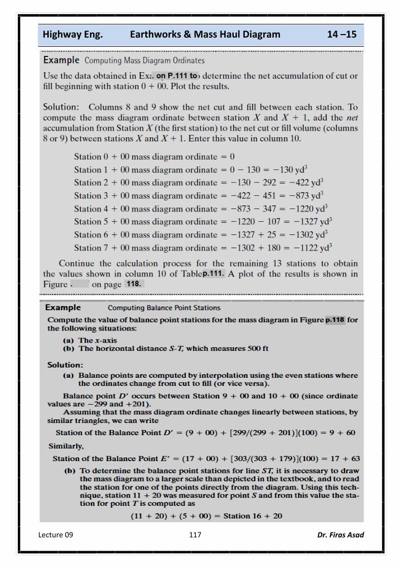
Mass Diagram for Computation Shown in Table on Page 111.

Lecture 09 119
Highway Eng. Earthworks & Mass Haul Diagram 14 –15
Dr. Firas Asad
Example: ( س�ؤال امتح�ان نص�ف الس�نة) The following table lists the cut and fill end areas along a 1 km roadway section. Calculate the earthwork volumes and draw the mass haul diagram. The fill soil would experience a 10% shrinkage. Also calculate the following:
a) Limit of economical haul distance. b) Free-Haul volume. c) Over-Haul volume. d) Waste and borrow volumes.
UGiving that:
Cost of Over-Haul = 1500 I.D./m3.sta. Cost of borrow = 6000 I.D./m3 Free-Haul distance = 200 m.
Sol.:
Sta. A cut (m2) A fill (m2) V cut (m3) V fill (m3) V fill (corr) Cum Vol (m3)
1+00 57
5000
3900
2500
1000
167
-
-
-
-
-
-
200
800
1600
2600
3250
2250
725
-
-
220
880
1760
2860
3575
2475
797
5000
8900
11180
11300
9707
6847
3272
797
0
2+00 43
3+00 35 0
4+00 15 06
5+00 05 10
6+00 0 22
7+00 30
8+00 35
9+00 10
10+00 4.5

Lecture 09 120
Highway Eng. Earthworks & Mass Haul Diagram 14 –15
Dr. Firas Asad
==============================================

Lecture 09 121
Highway Eng. Earthworks & Mass Haul Diagram 14 –15
Dr. Firas Asad