hints and kinks for the radio amateur - n5duxn5dux.com/ham/files/pdf/hints and kinks for the radio...
TRANSCRIPT

Hints and Kinksfor the
Radio Amateur
EditorRobert Schefgen, KU7G
Contributing EditorDavid Newkirk, WJ1Z
Cover design bySue Fagan
Production work byShelly Bloom, WB1ENTJodi Morin, KA1JPAJoe SheaDeborah SfrzfJskowskl
Published by• The American Radio Relay League, Inc.
Newington, CT 06111

Copyright e 1992 by
The American Radio Relay league, Inc.
Copyright secured under the Pan-AmericanConvention
International Copyright secured
This work Is publication No.1 0 of the RadioAmateur's library, published by the league.All rights reserved. No part of this work maybe reproduced in any form except by writtenpermission of the publisher. All rights oftranslation are reserved.
Printed in USA
Quedan reservados tOdos los derechos
ISBN; 0-87259-385-1
Thirteenth EditionSecond Printing, 1993
$9.00 In USA

Foreword=========Are you looking for fun in Amateur Radio? Many QST readers say they needlook no further than the monthly Hints and Kinks column. Each month, Hintsand Kinks brings QST readers the most creative ideas of other resourcefulhams. Every few years, the best of the recent SUbmissions are gathered upand reorganized into a convenient reference volume.
This edition of Hints and Kinks is the thirteenth in a line that stretches backalmost 60 years! A ham stepping out of a time machine from 1933 wouldscarcely recognize any of our modern equipment. We have wholetransceivers that are smaller than some vacuum tubes of that time! He or shemight recognize little in a '90s ham shack. One anchor is QST, but even thathas changed: Inside are articles about digital techniques and microwaveprojects. Many columns have come and gone, but one the time travelerwould recognize immediately is Hints and Kinks.
There is a reason for such long-lived popularity. Coming up with a betteridea-to meet a challenge, either making your station more competitive orjust a bit more comfortable-is fun. We all love it, because it brings AmateurRadio to life for us. Even better is seeing your idea published in Hints andKinks.
This book holds ideas from many hams-good ideas for any shack. Enjoythem, but don't stop there; come up with something better. let's see youridea in the next edition.
David Sumner, K1ZZExecutive Vice President
Newington, CTMay 1992

Preface==========This book is a compilation of material that originally appeared in the OSTHints and Kinks column from January 1987 through December 1991. Authors'addresses have been left as published in OST. Some of the addresses mayhave changed since publication. If you wish to write to an author, check thelatest Radio Amateur Gal/book for a current address.
All suppliers mentioned in this book appear in a Suppliers List at the back.The addresses in the Suppliers List were verified at the time of publlcation.

Contents=========Units of Measure and EquivalentsSchematic Symbols
1 Equipment Tips and Modifications1-1 AEA
AmeritronCollinsDrake
1-4 Heath1-12 ICOM1-19 Kenwood1-25 MFJ
Radio ShackTen-Tee
1-29 Yaesu1-32 Home-Built
2 BaUerles and Generators
3 Mobile Stations
4 Portable Stations
S Construction5-1 Design Hints5-10 Tools and Techniques5-18 Parts
e Test Gear
7 Antenna Systems7-1 Feed Lines7-11 Supports and Construction Techniques7-20 Rotatable Antennas7-24 Fixed Antennas7-29 Vertical Antennas
e Operating Techniques
9 Around the Shack9-1 Voice and Other Modes9-12 CW9-18 Packet
10 Electromagnetic Interference(RFI/EMI)
Abbreviations List
Suppliers List
Index

Units of Measure andEquivalents=======
MUltiply -Metric Unit = Conversion Factor x U.S. Customary Unit
.. DivideMetric Unit + Conversion Factor = U.S. Customary Unit
Conversion ConversionMetric Unit = Factor x U.S. Unit Metric Unit = Factor x U.S. Unit(Length) (Volume)mm 25.4 Inch mm3 16387.064 in3
cm 2.54 Inch cm3 16.387 in3cm 30.48 foot m3 0.028316 ft3m 0.3048 foot m3 0.764555 yd3m 0.9144 yard ml 16.387 In3km 1.609 mile ml 29.57 II 02km 1.852 nautical mile ml 473 pint(Area) ml 946.333 quartmm2 645.16 Inch2 I 28.32 ft3cm2 6.4518 In2 I 0.9483 quartcm2 929.03 ft2 I 3.785 gallonm2 0.0929 ft2 I 1.101 dry quartcm2 8361.3 yd2 I 8.809 peckm2 0.83613 yd2 I 35.238 bushelm2 4047 acre
(Mass) (Troy Weight)km2 2.59 mi2(Mass) (Avoirdupois Weight)
g 31.103 02 tg 373.248 Ib tgrams 0.0648 grains
g 28.349 02 (Mass) (Apothecaries' Weight)g 453.59 Ib g 3.387 dr apkg 0.45359 Ib g 31.103 02 aptonne 0.907 short ton g 373.248 Ib aptonne 1.016 long ton

U.s. Customary - Metric Conversion FactorsInternational System of Units (SI) - Metric Units U. S. Customary UnitsPrefix Symbol Multiplication Factor Linear Unitsexa E 1018 = 1,000,000,000,000,000,000psta P 1015 = 1,000,000,000,000,000 12 inches (in) = 1 foot (ft)tera T 10' 2 = 1,000,000,000,000 36 inches = 3 feet = 1 yard (yd)giga G 109 = 1,000,000,000 1 rod = 5'/2 yards = 16'/2 feetmega M 106 1,000,000 1 statute mile = 1760 yards = 5280 feetkilo k 103 1,000 1 nautical mile = 6076.11549 feethecto h 102 = 100deca da 101 = 10 Area
(unit) 100 = 1 1 ft2 = 144 in2
deci d 10.1 = 0.1 1 yd2 = 9 f(2 = 1296 in2
centi c 10.2 = 0.01 1 rod2 = 30Y. yd2
milli m 10-3 = 0.001 1 acre = 4840 yd2 = 43,560 ft2
micro I' 10-6 = 0.000001 1 acre = 160 rod2
nano n 10.9 = 0.000000001 1 mile2 = 640 acrespica p 10.12 = 0.000000000001femto f 10.15 = 0.000000000000001 Volumeatto a 10.18 = 0.000000000000000001 1 ft' = 1728 in'
1 yd' = 27 ft'
Linear1 meter (m) = 100 centimeters (em) = 1000 millimeters (mm)
Area1 m2 = 1 x 10' cm2 = 1 x 106 mm2
Volume1 m' = 1 x 10. em' = 1 x 10. mm'1 liter (I) = 1000 em' = 1 x 10. mm'
Mass1 kilogram (kg) = 1000 grams (g)
(Approximately the mass of 1 liter of water)1 metric ton (or tonne) = 1000 kg
Liquid Volume Measure1 fluid ounce (fl 02) = 8 fluidrams = 1.804 in'1 pint (pt) = 16 fl oz1 quart (qt) = 2 pt = 32 fl oz = 57'4 in'1 gallon (gal) = 4 qt = 231 in'1 barrel = 311/2 gal
Dry Volume Measure1 quart (qt) = 2 pints (pt) = 67.2 in'lpeck=8qt
1 bushel = 4 pecks = 2150.42 in'Avoirdupois Weight
1 dram (dr) = 27.343 grains (gr) or (gr a)1 ounce (oz) = 437.5 gr1 pound (Ib) = 16 oz = 7000 gr1 short ton = 2000 Ib, 1 long ton = 2240 Ib
Troy Weight1 grain troy (gr t) = 1 grain avoirdupois1 pennyweight (dwt) or (pwt) = 24 gr t1 ounce troy (oz t) = 480 grains1 Ib t = 12 oz t = 5760 grains
Apothecaries' Weight1 grain apothecaries' (gr ap) = 1 gr t = 1 gr a1 dram ap (dr ap) = 60 gr1 oz ap = 1 oz t = 8 dr ap = 480 gr1 Ib ap = 1 Ib t = 12 oz ap = 5760 gr

Schel118.tic SyDlbols\\PHOTO NON- SPLIT-STATOR AIR-CORE ADJUSTABlE FERRITE BEAD lFIXED VARIABLE fiXED
~---G-fr POLARIZED
-1Jf~rYJ()-'\/IIv- -'\/IIv- ~f- -If-IRON-CORE OR METERS
ADJUSTABLE TAPPED THERMISTORFEED- rYJ() rYfl 0~ ~
-'\/IIv- ELECTROLYTIC VARIABLETHROUGH
t· ~f± * -0---0- TAPPED
T rYfY' *-V, mv,RESISTORS CAPACITORS INDUCTORS A, rnA, ~A
+ h SPST SPOT NORMALLY OPEN BATIERIES
or= =p 0/'0 ~ --L.- )2 .t.jf=- .±.j II f-=TOGGLE 0 0 0 SINGLE MULTI-
CONDUCTORS CONDUCTORS SHIELDED WIRE OR COAXIAL CABLE CELL CELLNOT JOINED JOINED
00/NORMALLY CLOSED
---0 IIIi ~ c.l..o or GROUNDS
tTERMINAL ADDRESS OR DATA MULTIPLE CONDUCTOR rh *MULTIPOINTBUS CABLE MOMENTARY THERMAL CHASSIS A-ANALOGWIRING SWITCHES EARTIi a-DIGITAL
~ -.- ADJUSTABLE ADJUSTABLE
'YANTENNA~* ~E4 AIR CORE INDUCTANCE
~L£D (OS,) u..u.J
~ZENER TUNNEL
-lDf- -..A~~
rYJ()---.r-
<>QUARTZ
HAND KEY
DIODE/RECTIFIER
-$Wfn-l CORE WITH LINK ~ CRYSTAL
I IVOLTAGEu..u.J W ZVARIABLE eCAPACITOR rYJ() rYJ() ASSEMBLY OR
3-PIN CERAMIC MODULEDIODES (01) BRIDGE RECTIFIER TRANSFORMERS RESONATOR MOTOR (OTHER THAN IC)
MISCELLANEOUSNPN P-CHANNEL P-CHANNEl P-CHANNEl P-CHANNEl P-CHANNEl
B-©C E-eJ=BZG-@: G-@=: G-@=:
AND NAND
G2=@=D .o- ::D-Bl Gl SE
OR NORPNP N-CHANNEL N-CHANNEl N-CHANNEL N-CHANNEL N-CHANNEL :::L>- :::D--
B-©C E~B2G-@=: G-@=:
G2=®=DG-@=:
XOR INVERTER
Bl Gl S ::)D- -i>-E
BIPOLAR UJT JUNCTION rET SINGl£-GATE DUAL-GATE SINGLE-GATE SCHMITT IOTHER IDEPLETION-MODE--- ENHANCEMENT-MODE .IT
~ -@Y-". MOSFET MOSFET LOGIC (U,)A
GENERAL COMMONTRIAC GTHYRISTOR (SCR)
AMPLIFIER CONNECTIONS PHONE JACK PHONE PLUG
TRANSISTORS t> a ---/ LABEL t-- D~ o----r-~
CONTACTS
R --D- COAXIAL CONNECTORSSPST SPOTOf' AMP MALE FEMALE
FE"ALE~ ~"AL£0--- -7 >-CflLil THERMAL
--.J 03 t> INTEGRATED---.t CIRCUITS
SOLENOIDS RELAYS CONTACTS (U,) MULTIPLE. 240 V FEMALE
MOVABLE ( A ) (
'")
'1--- ruBE ELEMENTS ---
...l..- ANODEMULTIPLE, I '" I I y I(') HEATER OR FIXED
~.~ FILAMENT--- III--- GRID FEMAL£ "AL£ "ALE• GAS FILLED CHASSIS-MOUNTTRIODE PENTODE CRT
HOT~EU~HOT HOT?I"' CATHODE ? COLD 120V 120V 120 V NEUT
rNCANDESCEN~EON (AC) CATHODE
::ID (051) • LAMPS
TUBESGND GND GND(V" --< >- DEFLECTION PLATES
CONNECTORS

CHAPTER 1
EquipDlent Tips andModifications
L-__~ ~----'''''''''_''''''06
,56 •2W
56 k2W
1~0::'
01
keeping the PK-232's PTT output highregardless of whether the PK-232 is in CWtransmit or CW receive. This allows theIC-75IA's semi-break-in function to handleCW TR switching functions. When thePK-232 is in the RTTY mode, the CWNline is high and the '232 works as if thediode isn't there. Note: I haven't yet triedmy PK-232 on AMTOR or packet; I assumethat the diode will not affect operationof the PK-232 in those modes.-GuyOlbrechts, NY70, 4809 Jl6th Ave SE,Bellevue, WA 98006
ELECTRONIC BIAS SWITCHING FORTHE AMERITRON AL·1200o Adding electronic bias switching (Fig 2)to the Ameritron AL-1200 grounded-grid3CX1200A7 amplifier allows noiselessbreak-in when an electronic TR switch isused. Because this circuit biases the tubeoff in the absence of excitation, it can
R1 R2
56 k ..aJ!.2W ZW
1N4007
Except u lndlcat«l, declmll Vllulll ofcapacltll'lC8 If8 in mlcrolarads (,iF);OIhlrl1111 in plcolara (pf); mlsllllCeS Ire Inohms:k _ 1000.
FRONT PANEL
+
u..!.ZW 1N914
BANO. CATHODE
U37 U39 U38
7406 741..504 7406
.E1-Btl'N 10
~@) @) @)
Fig 2-Hank Garretson added electronic bias switching to his AL-1200 with this circuit.The 12-pF, O.01-j£F and O.015-j£F capacitors are ceramic. Connect Terminals 1 and 2 to120 V ac at the primary of the AL-1200's heater transformer, Terminal 3 to the center tapof the AL-1200's heater transformer, and Terminal 4 to the RF·IN terminal on the AL-1200'sALC/Power Board AR-574; do not change the AL-1200's wiring for these steps. Break thewhite wire between contact A of RLY1 and the RLY terminal on Meter Board AR·545 inthe AL·1200. Connect Terminal 5 to contact A of RLY1 on the AL-1200, and Terminal 8 tothe RLY terminal of the AL·1200's Meter Board AR-545.01, 02-2N5855. Alternatives: 2N5658, 2N5657, 2N4055. 2N4056. NTE 157. MJE3439,
MJE3440, MJE9741, MJE9742.T1-lsolation transformer, 120-V primary and secondary (two low-current filament
transformers connected back-to-back will also work),
Fig 1-Guy Olbrechts solved hisPK-23211C-751A compatibility problem withthis modification. Addition of a diode, D.disables the PK-232's PTT output duringCW operation, allowing the transceiver'skeyed VOX circuitry to handle TRswitching. D Is a silicon switching diode(1N914, 1N4148 and others suitable). Seetext.
'PK·232Operating Manual. p 4-4.
SIMPLER CW/RTTY MODECHANGES WITH THE AEA PK-232
o After I'd sorted out various options forequipment control and interconnection,CW and RTTY operation with my Advanced Electronics Applications PK-232multimode communications processor andIC-75IA transceiver went well-except forone snag. I prefer to copy code aurally anduse the PK-232 only to transmit during CWoperation. To do this, as the PK-232manual says, you must "disconnect yourmicrophone cable from the PK-232 to theradio so that the radio does not hang intransmit. "I The culprit is the PK-232-totransceiver PTT-line connection, which, inmy setup, must be present for RTTYoperation but absent during CW operation.Without this connection, the PK-232 cannot switch the IC-75IA into RTTY transmit; with this connection, the IC-75IAtransmits a continuous carrier when thePK-232 is commanded to transmit CW!The need to plug and unplug this connection-or install a switch in the PTT lineseemed to be an unnecessary complicationof an otherwiseelegantPK-232/IC-751A1PCsystem. There had to be a better way!
There is. Lacking the program documentation necessary to figure out a suitablesoftware PTT switch, I looked for anautomatic hardware solution. The PK-232schematic shows signal lines labeled CWand CWN. I suspected that the state ofthese lines would indicate whether or notthe PK-232 isin the CW mode. Tests confirmed my hunch.
Armed with this information, I disabledthe PK-232's CW-mode PTT output byadding just one component-a siliconswitching diode-to the '232. I installed thediode between U37 pin 12 and U38 pin 10,with its cathode at U37 pin 12 on thePK-232 circuit board (see Fig I). U37 andU38 are close together, allowing the diodeleads to be soldered right to the IC pins.
This modification works as follows: Thefifth section of U3g (U38 pins 10 and II)is in series with the '232's PTTN line.PTTN is low when the '232's PTT outputgoes low to switch the associated transceiver into transmit. The signal at U38 pin10 is high in this situation. With the diodeinstalled, however, the '232's CWN linelow when the PK-232 is in CW modepulls U38 pin 10 low tbrough the diode,
Equipment Tips and Modifications 1-1

Fig 3-Mike Agsten reduced de-to-de converter-related TR·7 spurs by replacing the rig'sC2108 and adding three filter components (C't, C2 and 11) as shown here. 11 consists ofno. 24 enameled wire wound to fill a junk-box V2-inch-OD ferrite toroid.
21/10+10 V DC:EG OUT
Break 11RfC2101 Connection (See relit)
from \ -- ==Inverter +1 C210a
' ,+1 ci + C2
~220~F (Replace;~220~F ~'0~F16V See Text) 16 V 16 V
I J l Jr rOriginol N••
lengthen the life of your 3CX1200A evenif you don't operate break-in.
The circuit is an adaptation of similarschemes by Clements- and Piuenger.? Twoparallelled 56-kilohm resistors (RI and R2)are placed in series with the stock AL-1200bias circuit. With no excitation applied, Qland Q2 (a Darlington amplifier) are turnedoff, and voltage drop across Rl and R2produces sufficient bias to cut off theAL-I200's 3CX1200A7. Excitation, rectified by 01 and 02 and filtered by CI, turnsQI and Q2 on, bypassing RI and R2 andapplying normal operating bias to the tube.
Mount the circuit components on a pieceof perf board and install this module abovethe AL-1200 circuit boards (immediatelybehind the amplifier meters). Caution:Voltages in the AL-1200 can kill you.Unplug the amplifier and ground the3CX1200A7 plate connection before working on the amplifier.-Hank Garretson,W6SX, 18831 Capensesc Fountain Valley,CA 92708
2P. Clements, "All Solid-State aSK for the Heath8B·220," OST, Jan 1980, PP 25·27.
3J. Pittenger, "3CX1200A7 10 to 80-MeterAmplifier," ham radio, Aug 1985,pp 75-78, 83,84·85, 87.
BETTER SSB FOR THE COLLINSR-390 RECEIVER
D The Collins R-390 is a great receiverexcept for its poor performance on SSB.The primary reason for this fault is animproper signal versus BFO level in thedetector stage; with the BFO as weak as itis, the '390's AGC range is insufficient toensure undistorted reception of strong SSBsignals. The addition of a single 33-kOresistor between the anode of the AGCrectifier tube (pin 6 or 7 of V51O) and thegrid of the AGC time constant tube (pin7 of V511) gives the AGC a helping hand,producing excellent SSB quality.
You can test this modification withoutremoving the R-390's IF subchassis asfollows: Extend the leads of a 33-kQ,12-watt resistor by soldering a length ofsolid, insulated hook-up wire to eachresistor pigtail. Wrap the resistor and itsleads with insulating tape. Next, strip bothof the extended resistor leads for 12 inch.Remove tube V510 from the R-390 IF subchassis and tightly wrap the bare end of oneresistor lead around pin 6 or 7 at the tubebase. Reinstall the tube, being careful thatthe twisted resistor wire remains insulatedfrom the other tube pins and shield basewhen the tube is seated. Connect the otherresistor lead to pin 7 of V511 in the samemanner. Excellent SSB performance shouldbe noticed, with no adverse affects on AGCtime constant.
A more permanent modification wouldinvolve placing the 33-kOresistor in parallelwith the series combination of resistorsR556 and R557 inside the IF subchassls.-Ken Johnson, N5US, PO Box 10063,Austin, TX 78766
1-2 Chapter 1
BETTER SSB FOR THE COLLINSR-390A RECEIVER-REVISITED
o Some receiver aficionados think that theR-39O and R-390A are identical except fortheir method of IF filtering, (The R-390uses LC IF filtering; the R-390A usesmechanical filters and is generally considered to be more desirable because of
.this.) The R-390A is actually a pared-downR-390: It has one fewer RF amplifier andtwo fewer IF amplifiers than the '390. Thisseems to make the R-39O a little moresensitive than the '390A, The '390 and390A also differ in their power supplies andtube complements. These differences makecircuit modules and most parts noninterchangeable between the two receivers.
My modification concerns the R-390'sAGC circuitry; the AGC circuits in theR-390 and R-390A are similar. Bothreceivers use 12AU7/5814 tubes for AGerectifier and AGC-time-constant functions;however, the part numbers and tube-pinreferences differ between the two receiversfor the circuitry that serves these functions.Anyone wishing to improve the SSBperformance of an R-390A by trying mymodification should consult a schematicdiagram of the '390A for circuit details.Please note that I have not attempted thismodification on an R-390A; the basic ideashould be applicable to this receiver,however,-Ken Johnson, N5US, PO Box10063, Austin, TX 78766
CURING DC-TO-DC CONVERTERSPURS IN THE DRAKE TR-7TRANSCEIVER
D Is your TR-7 transmitting and receivingspurious signals 23 and 46 kHz above itstuned frequency? Checking this is easy.With a 50-ohm dummy load attached toyour TR·7's antenna jack and the transceiver in a narrow CW mode, turn on theTR-Ts 25-kHz CALibrator and tune in the1800-kHz marker. Now, tune for a signal
at approximately 1802 kHz (1825 - 23),If you find an 1802-kHz signal, turn off thecalibrator to see if the signal disappears atthe same time. Spurs of the type discussedin this hint disappear when the calibratoris turned off.
In my case, the spurs registered S5 on theTR-7's S meter, while the 25-kHz markerscame in at 15 dB over S9. This "multichannel" response degraded my TR-7'sability to receiveweak signals. O·n transmit,other hams heard me at several unexpectedplaces on the band-at reduced strength,but still quite readable.
Replacing"C2108, a de-to-de converterdecoupling capacitor on the transceiver'sinternal power-supplycircuit board (Fig 2-23in the TR-7 Maintenance Manual), reducedthe spurs to S2. This is acceptable, butadding another pi filter section in cascadewith RFC2101/C2108 (Fig 3) pushed thespurs into the noise.
There's plenty of room on the back ofthe power supply board to "kludge in" thenew parts. The added filter inductor (Llin Fig 3) is a junk-box Y2-inch-ODferritetoroid filled with no. 24 enameled copperwire,-Mike Agsten, WA8TXT, 405 WBogart Rd, Sandusky, OH 44870
USING THE DRAKE TR-? AND TR-7ATRANSCEIVERS WITH FULL-BREAKIN AMPLIFIERS
o The Drake TR-7 exhibits a characteristicthat makes it difficult to use with severalfull-break-in (QSK) amplifiers on themarket (ETO models Alpha 77, 78 and 86,and the Ten Tee 425), The problem is thatthere is RF at the TR-7!7A's ANTENNA
jack before the transceiver's VOX relay hasclosed. This condition activates theamplifier's "hot-switch protect" circuitry,causing the amplifier not to amplify thefirst dot or, in the case of the Alpha 86,to trip the protection latch and not amplifyat all. In SSB VOX operation, a similar

Fig 5-The 4.7-kO resistor and transistor are connected to the TR·7I7A motherboard asshown at A. If you use a 2N2222 in a metal can (TO-39, pinout at Inset), be sure that thecan does nottouch other components.
4.7 sn,+ toT o-~VV-H
Fig 4-Dick Freyadded aSK compatibilityto his Drake TR-7 trensceiver by adding a4.7-kO resistor, NPN transistor (2N3904 or2N2222), 5-inch piece of wire and panellabel to the rig. The aSK jack is a sparephono connector already installed on theTR-7I7A back panel by Drake. See text andFig 5,
condition exists, but is less pronounced.The Drake's VOX relay, which takes
approximately 10 ms to close, is the causeof this problem, The solution is to add atransistor switch (Fig 4) to the TR-7-aswitch that closes immediately on thegeneration of a transmit command fromthe key, PIT or VOX. Once this is done,the transistor switch, not the TR-7's VOXrelay, keys the amplifier. The circuit is easyto build and can be installed by a reasonably competent technician in less than 15minutes. No familiarity with the innerworkings of the Drake is required.
Refer to Fig 4, Circuit operation issimple: The + lOT line goes from zero to+ 10 V when the TR-7 goes from receiveto transmit, regardless of the position ofthe transceiver's MODE switch. This turnson QI, which keys the amplifier.
Drake has graciously placed a sparephono jack on the transceiver's rearpanel;we'll use this jack for the new amplifiercontrol output. Once you've collected theparts listed in the Fig 4 caption, proceedas follows:
I) Remove the TR·?'s cover (slot-headscrews) and bottom plate (Phillips-headscrews).
2) Remove the six screws that hold therear center panel. This allows access to thespare phono jack's solder terminals.
3) Solder one end of the 5-inch wire tothe center pin of the spare phono jack and
route the wire toward the bottom of thepanel.
4) Replace the rear panel and its sixscrews.
5) Turn the TR-7 over and locate the+ lOT trace on the large circuit board (themotherboard; see Fig 5).
6) Solder the emitter lead of the transistor to the ground pad of the coaxial cableclosest to the rear center of the board.
7) Solder the free end of the wire fromthe QSK jack to the collector lead of thetransistor.
8) Solder the 4.7-kOresistor between the• lOT trace and the transistor base lead. Becareful that the leads of the transistor donot short any traces on the board.
9) Label the new jack QSK with tape ora stick-on label.
10)Check your work. Replacethe TR-7'sbottom cover (Phillips-head screws) andtop cover (slot-head screws).
To use the TR-7 with the amplifier, connect the new QSK jack to the RELAY or KEYIN jack on the amplifier. No other controlconnections are required.-Dick Frey,K4XU, 4138Maine St, Quincy, IL 6230/
Equipment Tlpe and Modlflcatlone 1·3

Heath
OUTPUTPI~--1f----<o
(A)+
12 V
T 0.01
rh~F
47 k n
0.01~F
1
n 1~~1
150,uH
G
USING THE HEATH HR-1680RECEIVER AS A CW MONITOR
o I prefer to monitor my CW signal withthe station receiver rather than with a sidetone oscillator because a sidetone doesn'treally tell me how my transmitter sounds.Changes in the tonal purity or frequencyof the transmitted signal are immediatelyapparent when the receiver is used as amonitor. (Of course, this assumes that thereceiver is stable enough to provide anaccurate representation of transmitterstability.) Also, this technique allows meto escape from the monotony of sidetonemonitoring because I can change the pitchof the monitor signal at will by tuning thereceiver as I transmit.
MAX
k ~ 1000
GND
WIDE/OUT i--~E3~,-..:~-"...e=---/
HW-9T/R Boord
(B)
lCOk.f"l..~ MONITOR
. t . 1 LEVEL K 1
M'N jL----------0--
<.}------'\Nv----+--=--':'-'----",TO \--HR-1680 ....rMUTING
JAC K
Fig 6-Used in conjunction with a spareset of closed-during-transmlt .relay contacts(K1) in the station transmitter or TR switch,Terry Lyon's MONITOR LEVEL control allowshim to monitor his keying with his HR-1680receiver.
Fig 7-Thomas Niedermeyer added a narrow CW filter/amplifier (A) to his HW-9transceiver and included this circuit in the HW-9's Wide/Narrow bandwidth SWitching. Bshows the stock HW-9's Wide/Narrow bandwidth switching; C shows the modified circuit.FL1 is a FoxfTango 2801.1; see Note 4, This modification requires the HW-9's originalC313, a O.001-jtF disc, be removed as described in the text. Note that this capacitor isreplaced by "New C313" at C. 01 is a 1N4000-series diode.
to pin 4,UJ01
(see text)
toCJ1J-RJOB
junction(see text)
N••CJ1J
1---/0.001 #F
K1C
to RJ,AF GAIN
to12VatCJ55-RJ72
junction
K1A _l D1 WIDE
~SW3IARROW
K18
+
(e)
+12 V
New Filter/Amp Board
GNO GND
12V
~=E---<i INPUT OUTPUT?----1~=~j--
GND
WIDE/OUT ?--~E39--
NARROW/OUT ?--~E39--,GND
toRJ07-CJOBjunction onT/R Boord(see text)
Using my Heath" HR-1680 receiver forCW monitoring presents a problem,however, because its AGC range can'thandle my transmitter's strong signal. Thisresults in the generation of clicks, thumpsand spurious signals that aren't present onthe transmitted signal. To solve thisproblem, I installed a simple gain controlcircuit in the HR-1680's muting line(Fig 6). With proper adjustment of theMONITOR LEVEL control, this circuit drastically (but not completely) reduces theHR-1680's RF and IF gain when the mutingline is grounded for transmission.-Terry L.Lyon, KA3GCQ, 3 McCann St. Edgewood.MD21040
A NARROW IF FILTER FOR THEHEATH HW-9 TRANSCEIVER
o The Heath HW-9 is a fine CW QRP rig.H features a sensitive, stable receiver withexcellent dynamic range and good AGC.For serious CW operation in a high-QRMenvironment, however, I find it deficientin selectivity. The HW-9 achieves its IFfiltering with a four-pole crystal filter thathas a - 6-dB bandwidth in excess of 2 kHz,and skirts that are 4 to 6 kHz wide at - 40to - 60 dB. This is fine for tuning aroundthe band, or listening to SSB, but inadequate for narrow-band CW work. TheHW-9's audio filter, selected in the Narrowmode, works well for cutting out adjacent
1-4 Chapter 1

ceiver has a frequency-stability problem.'This bothered me because I like to go onthe air at the spur of the moment: I don'talways have time to let the transceiverwarm up for an hour!
I looked into the problem and realizedthat the can holding the parts that controlthe HW-99's frequency is awfully close tothe pilot lamp-and that lamp gets quitehot. Removing the pilot lamp solved thedrift problem. I thought I'd share this hintwith you in case other readers who'veencountered this HW-99 stability problemmight like to try a simple solution.-NancyKou, KB8FA Y, PO Box 47, Hadley, MI48440-0047
ELIMINATING DIAL-DRIVECLUTCH SLIPPAGE IN THE HW-IOIo After I became the third owner of aHeathkit HW-101 transceiver, I noticedthat its VFO occasionally slipped out ofcalibration at the ends of its range. I discovered the cause after removing the VFOassembly from the rig to inspect the dialdrive clutch: After years of pressure, theplastic clutch (Heath part no. 266-200)hadwarped. I reversed the clutch disk so thatthe inside surface of the disk faces outward,making the warpage work in my favor.Now, the dial drive works well. The clutchallows just enough slippage for manualcalibration of the VFO dial scale.- VernonD. Range, Jr"KA9NBH, Rochelle, Illinois
IMPROVING RIT AND SPLITFREQUENCY OPERATION IN THEHEATH HW-5400 TRANSCEIVERo I found CW operation in theHW-5400's "split-frequency" modecumbersome because of a delay betweenkey closure and RF output. A call toHeath" confirmed that this delay isinherent in the HW-5400 because time isrequired to reset the frequencies of variousoscillators-in particular, the microprocessor clock-when changing from receive totransmit. Wanting to reduce the delay, Iwondered if the oscillator-reset time couldbe shortened. (I also wanted to be able tooperate at splits wider than those possiblewith the '54oo's ±350-Hz RIT [receiverincremental tuning] range; increasing theRIT range by adding diode D70IB per alater revision of the '5400's assemblymanual did not increase the range enoughfor my purposes.)
Finally, I hit upon a solution: Use twomicroprocessor clock oscillators-one forreceive and the other for transmit-andswitch between them instead of tuning the'5400's crystal-controlled clock betweentransmit and receive frequencies. Theoscillator circuit I use (Fig 8) was designedby Lyle Audiss, K6PlE, and has givengood results. This LC oscillator operatesat the same nominal frequency asthe HW-5400's crystal-controlled clock(8.04 MHz) and can be switched in to serveas the clock on receive. Because the LCoscillator can be tuned over a wider rangethan the crystal oscillator, the LC oscillator
Equipment Tips and Modifications 1-5
5C. and E. Holsopple, "Heath HW·99 Novice CWTransceiver," Product Review, QST, Mar 1986,pp 43-45
o I am a new ham, and my station includes an HW-99 transceiver. As noted inQSTs review of the HW-99,5 this trans-
o Strong signals near or in the HeathkitHW-9's IF passband can cause weakersignals in the passband to be distorted or"pumped" by AGC effects in the transceiver's high-gain IF-amplifier stages. Asdesigned, these stages run at full gain, andthere is no panel control for adjusting theirgain. Here's an easy modification thatsolves this problem.
During alignment of the HW-9, R329(AGe SET), a 5OO-kll circuit-board trimmerpot, is set and not adjusted again. Throughexperimentation, I discovered that R329allows the transceiver's IF gain to bereducedenough to minimize AGe pumping.I replaced R329 with a chassis-mountedcontrol to allow routine adjustment of theHW-9's IF-amplifier gain.
Remove the original R329 from the PCboard and discard it. Mount R329's shaftdriven replacement-I used a 500-kO linearcontrol from Radio Shack-on the HW-9chassis. (There is ample room on the chassisfor the control. I elected not to place thecontrol on the HW-9's front panel, insteadinstalling it on the transceiver's side (left,viewed from the front.]) Connect the newcontrol to the R329 circuit-board holes viaa piece of RG-174 coax.
The only readjustment necessary afterthis modification is a slight touch-up ofR333 (METER ZERO). Now, your HW-9 canperform better in the presenceof strong signals: Using the panel-mounted R329,simply reduce the IF-amplifier gain to thepoint at which AGC pumping disappears.Adjust R329 for full receiver gain as necessary.-Jim Douglas, NI2F, 9 Linda Ln,Clark, NJ 07066CURING THERMAL DRIFT IN THEHEATHKIT HW-99 TRANSCEIVER
unnecessary because they're grounded attheir non-SW3 ends. Just cut off theirSW3-end braids about !.-1 inch away fromtheir center conductors.)
Connect one relay-solenoid (KIA) terminal to 12 V de at the C355 side of R372,and connect the remaining KIA terminalto the center contact of SW3. Install aIN4000-series diode across the solenoid terminals, cathode to .the solenoid's 12-Vsupply end. Connect the appropriate SW3contact to the adjacent ground lug. SW3now switchesthe relay between Narrow andWide according to the front-panel legend.
Check your work, fire up the rig andadjust RI (GAIN) so that in-band signalsshow the same S-meter reading througheither filter. Happy QRPing!-ThomosNiedermeyer, NK6E, PO Box 301, Fairfield,1A 52556AN AGC-THRESHOLD CONTROLFOR THE HEATH HW-9TRANSCEIVER
signals that are relatively weak-but if theyare strong enough to activate the AGC (thetake-off point for which is ahead of theaudio filter), the desired signal oftenbecomes unreadable. This deficiencycan bereadily overcome by adding a narrow IFcrystal filter. Fortunately, Heath designedthe HW-9 with an 8.8307-MHz IF, whichexactly matches the IF center for CWreception in some Kenwood transceiversand narrow CW filters are available for thisfrequency.
I purchased a steep-skirted 250-Hz filter,the Fox/Tango 2801.1.' and installed it inmy HW-9. It works well, but because it'stoo narrow for band scanning, I decidedto use it only in the HW-9's Narrow mode,keeping the rig's originaI2-kHz- wide filterin Wide. The HW-9's narrow audio filter,although not needed when the F/T 2801.1is in line, does a fine job reducing widebandnoise generated by the HW-9's IFamplifier, so I keep it active in the Narrowmode.
Because of the F/T 2801.1's relativelyhigh insertion loss, however, I found thatsome amplification is necessaryto maintainproper gain and S-meter readings. Fig 7Ashows the circuit I devised to provide this.A junction FET ahead of the filter providesa high input impedance and some gain, anda similar stage at the filter output suppliesadditional, and adjustable, gain. This circuit, along with the filter, can be built ona small piece of perfboard (or a circuitboard) and is mounted on the side of thechassis below the U302 area of the HW-9'sT/R board. I made the modificationwithout removing either of the HW-9's twocircuit boards.
The input lead of the filter board connects across R307 (on the HW-9's T/Rboard) using small-diameter coax. Exposea circuit point suitable for switchingbetween the outputs of the new and original filters by removing C313 (a ceramicdisc) by carefully crushing C313 withneedle-nose pliers and removing all of itsremains except for its leads. Mount a smalll2-V-dc, DPDT relay (KI in Fig 7C) sideways atop of FL301 using double-stickfoam tape, so that its pins face U30l, thesecond IF amplifier. Use the closest-to-thecircuit-board set of contacts (KIC, Fig 7C),connected via coax and a O.OOI-#tF disc, toswitch U301's input (pin 4, accessibleat theC313 lead closest to C322)between the output of the original filter (the remainingC313 lead) and the output of the newfilter/amplifier board. Use small-diametercoax for all RF T/R-board-to-KI connections.
Next, disconnect the shielded wires fromthe WIDE/NARROW switch (SW3) and connect the inner leads to the second set of therelay contacts so that the Narrow mode isactive along with the narrow CW filter.(Rerouting of the shielded-wire braids is
"The FoxlTango 2801.1 fitter is identical to lnter-national Radio's filter no. 97. Both are availablefrom International Radio and Computers Inc.

+'V
R704
SW3AGC
60 03
Q5 COLL.ECTORFIG a
lettering on the HW-5400's front panel.Any ideas?-Gary Audiss, N6SI, 6540Birch Dr, Santa Rosa, CA 95404
R702
Q70t
CONTROLLERBOARO
L701
RI22kA
Z+12V
,----1----1----·----
RX TXP902 P903
BROWN
AX.FIG 8
vox
6 3
'¥' • ,, , ,
SW' SW'TUNE NOR/WIDE
P914 - 3
(GROUND)
Fig 9-The Audlss wide-RIT circuit usesthe HW-5400's vox push button toswitch between normal and wide RIT.Broken connects are indicated by X.See text and Fig 8.
above and below the nominal transmit frequency. That's it! The problem I haven'tsolved is that of labeling SW4 to match the
allows a much wider RIT swing than thatpossible with the clock. (The clock [Q701and its associated 8.04-MHz crystal] is retained as the microprocessor clock ontransmit.) I use the HW-5400's vOX/PITswitch, SW4, to switch between normal andwide RIT (see Fig 9); I don't operate VOX,and using SW4 avoids the necessity ofadding another switch to the rig's frontpanel. PIT operation of the HW-54OO isunaffected by this modification.
The wide-RIT oscillator circuit is builton a double-sided PC board about 1 x 1Y2inches in size. Ll is wound on a junkboxslug-tuned form approximately 1/4 inchlong and 1/8 inch in diameter. The windingconsists of 17 turns of no. 28 enameledwire; place the tap at 5 turns from theground end of the coil.
Disconnect the VOX lead (a brown wire)from terminal 5 of SW4, tape the end ofthe wire, and fold the wire out of the way.Disconnect terminals 3 and 6 of SW4 fromground (the wire that goes to pin 3 ofP913). Install a 22-klJ, i4-W resistor inseries with the TX line to SW4, pin 3. (Thisresistor drops the TX voltage [approximately 12] to the 5 V necessary for biasingQ701.)
Mount the wide-RIT oscillator board ona standoff at the corner of the Controllerboard (directlyabove the 8.04-MHzcrystal).Connect the collector of Q5 (the wide-RIToscillator's output transistor) to the collector of Q701 (on the '54OO's Controllerboard) by means of a short pieceof RG-174coax. Connect point A of Fig 8 to pin Aon the Controller board.
Assuming that you've successfully builtand instailed the wide-RIT oscillator board,and you've completed the necessary wiringmodifications around SW4, the only stepleft is the adjustment of Ll. With theHW-5400 on and receiving, switch SW4 toWIDE RIT and adjust LI so that the RITcontrol swings the receiver tuning equally
osc
+12 V
100
~"':>o.---E=t===::"'; Q701~ COLLECTOR,
"'--_LJ FIG 9
O.2N3904
9VO,4W
330
.6 k
3303MPFl02
22
LI(SEE TEXT) 22
lN914 100 ~
0'2N2222
012N2222
TO PIN A, o-......~J\j.~- .....CONTROLLER
CIRCUIT 1°'001BOARD
TUNING DIODES
AMPLIFIERS
Fig 8-:-This oscillator allows Gary Audiss to use his Heathki~ HW·5400 transceiver at splits much greater than possible with the rig'sRIT Circuitry. Decimal-value capacitors are disc ceramic (16 V or greater); the 22- and 236-pF capacitors are NPO or COG discs.(Alt~ough Gary specifies a 236-pF ~~pacitor at C1, you can use several standard-value capacitors in parallel to approximate that value.)aeeietcrs are Y4-W, carbon-ccmpoattlon or -film units. See text and Fig 9.1·6 Chapter 1

HW-5400 SPEEDY TUNE
o After working a major SSB/CW contestwith my Heath HW -5400 transceiver, Irealized that I need a faster and easiermethod of changing frequency than thatallowed by the stock '5400. The circuitshown in Fig 10 is my solution to thisproblem. Dubbed the Speedy Tune, it provides rapid up/down frequency slewing andis controllable by a momentary, DPDT,center-off toggle switch. The Speedy Tuneis easy to build and does not affect the'54oo's manual tuning.
The Speedy Tune circuit is based on a555 timer, VI. The 555 is connected as anastable multivibrator that free runs at eighttimes the tuning rate (in steps per second)desired. The multivibrator frequency isadjustable by means of RATE control RI.U2 delivers two pulse trains 180 0 out ofphase which, when divided by binarycounters U3 and U4, produce two pulsetrains 90' out of phase (in quadrature)just as does the optical shaft-rotationencoder associated with the HW-S400'stuning knob. These signals are routed tothe <;1>1 and <;1>2 inputs of the HW-5400'scontroller board by means of UP/DOWNswitch SI.
My version of the Speedy Tune is builton a small piece of perfboard and mountednear the HW-5400's Controller board.(Power for the Speedy Tune is obtainedfrom P703 on the '5400's Controller board:Pin I supplies 5 V dc and pin 3 is common.)81 can be mounted on the '54oo's frontpanel-to the lower right or left of thetuning knob-with room to spare. TheSpeedy Tune circuit may also be usablewith any other optically-encoded tuningsystem that accepts TTL-level inputs from
its shaft encoder .-Dexter King. AB4DP.6438 Pettus Rd, Antioch, TN 37013
BATIERY BACKUP FOR THEHW-5400 TRANSCEIVER
o The Heath~ HW-5400 loses its memorywhen power fails. To solve this problem,connect three AA NiCd cells in series between pin 4 of U7l0 and ground, + terminals toward pin 4 of U71O, and - terminalstoward ground. (Easy access to pin 4 canbe had at R744; the NiCd cells can bemounted on the U714-U715 heat sink.)When the rig is on, the battery tricklecharges through pin 4 of U71O; when therig is off, the battery supplies 3.6 V for
. memory back-up. Install a diode-a IN914is suitable-between pin 4 of U710 (diodecathode to pin 4) and the HW -5400's 5-Vmemory-back-up line to keep the batteriesfrom discharging through the memoryback-up power supply.-AI Smardon,VE30X. RR I. Carrying Place. ON KOK/LO. CanadaAVOIDING STATIC DAMAGE TO THEHEATH i<MATlC MEMORY KEYER
o Heath suggests that users of the jtMaticMemory Keyer ground themselves toprotect the jtMatic's components fromelectrostatic discharge (ESD). ESD dangeris especially high on winter days when therelative humidity in heated buildings is low.Fig 11 shows my solution to this problem:a grounded metal strip that I touch eachtime my hand goes to the ~Matic paddles.The strip consists of self-adhesive, stainlesssteel tape (available in hobby or "homecenter" stores). The rubber pad alsoprovides an antislip base for the keyer.-John DeCicco, KB2ARU, 1816 Ave S.Brooklyn, NY l/229
Sell-Adhesive Metal Tape
Fig 11-John DeCicco protects his ItMatickeyer from static-electricity damage with agrounded length of self-adheslve steeltape. The rubber pad supports the tapeand keeps the keyer from sliding on thetable. Approaching John's antistaticmeasures from a commercial angle,computer stores carry "groundable"resistive strips and mats intended toprotect computers and keyboards fromESD; such products would also protect theItMatic. Hints and Kinks suggests installinga 1-megohm, t-watt resistor (or a seriesparallel resistor combination of equivalentresistance and power rating) between themetal strip and ground to limit current inthe strip ground to an operator-safe level.
AMPLIFIER TR RELAY SWITCHINGINVERSION
o Because I burned out a relay contact inmy Drake TR-5 transceiver by switching theantenna relay in my Heath" SB-200amplifier, James Hebert's January 1988article on a solid-state antenna-relay switchcaught my attention.6 I wanted to use
6J. Hebert, "Using the S8·220 Amplifier withSolid State Transceivers," page 1·9,
S16
0--0---0 JZI2 INPUT *
UPI DOWN
51A
0--0---0 11l11NPUT *
U3+ov7493
J~:'I, COUNTER
vee e ,p..It
"lr:r:
OFF,~N4" INPUT B
IOk{t tCLR t PR "CO e '"'~'" "00 ,3 i o toROW RO(ZI
RAeAI
" 'I'MIt , a (CLK ,,6 1'0'r~>------' '"'TRIG 7
I----'- ,"' I,O'Ol}lF
rL '"' rh "CO orrf,
, ,INPUT B "U2
OFF7474
" DUAL 01,000 '55 FLIP-FLOP DOWN\,000,000 TIMER '"~UNUSED PINS: RO(l) RO(Z) U.CONNECTiON
12 I'
7493COUNTER
N HW-5400 CONTROLLER BOARD
r t-r
P703,PIN 3
.'
M'ALL:~O
*0
P7D3,
PIN 1*
Fig 10-Dexter King's Speedy Tune circuit adds up/down frequency slewing to the Heath HW·5400 transceiver. R1 allows adjustment ofthe slewing rate.
Equipment Tips and Modifications 1-7

Fig 12-Wilbur Fulton modified the K8SS antenna-relay control circuit for use with the~B-200's negative ~ntenna-relay supply as shown here. J1 and K1 are S8-200 parts; 01IS a.1-A, 600-PIV diode; D2 and D3 are 1-A, SO·PIVdiodes and 51 is an 5P5T toggle.Resistors are V4-W, carbon-film units unless designated otherwise.
k =1000
.-------==-0 10 58-200+ relayr control jack
G
Heath" SB-2oo amplifier with a newlyacquired Kenwood TS-940S transceiver.The hot contact of the SB-2oo's relaycontrol jack exhibits an open circuit voltageof - 130 to ground; the short-circuitcurrent of the SB-200's relay-control circuitis 50 rnA. The open-circuit voltage couldrise to as high as 170under fault conditionsin the SB-200. The Kenwood manual statesthat the TS-940's control relay is intendedfor low-current applications; I infer that"low current" also means "low voltage."As a result, I did not want to connect theSB-200's 13o-Vcontrol line to my TS·940S.Instead, and in order to get on the airquickly, I used a relay between the TS-940Sand SB-2oo. I wasn't satisfied for long: Itseemed ridiculous-and rather noisy-touse the transceiver relay to drive anotherrelay that finally switched another relay inthe SB-2oo.
To solve this problem, I designed aninterface circuit (Fig 13) that uses a highvoltage, P-channel MOS power transistor-an IRF9612-as a switch. The IRF9612has a source-to-drain breakdown voltage of200, can switch up to 1.5 A, exhibits achannel resistance of 4.5 0 when turned on,comes in a TO-220 plastic package, andcosts $3.50/unit in small quantities. TheIRF9612 also includes an integral drain-tosource protection diode capable of clamping transients that can result from switching inductive loads.
The circuit is powered by a 9-V battery,which provides enough voltage to drive theMOSFET in this low-current switchingapplication. The I-kG resistor limits thepeak current flowing in the transceiver relayto approximately 9 rnA and sets theMOSFET turn-on time to approximately0.3 I's (this assumes that the MOSFET'seffective input capacitance is 300 pF). The470-kO resistor sets the turn-off timeconstant to 140 J1.S and limits the closedcircuit current to 20 pA. The 15-V Zenerdiode protects the transceiver should theMOSFET develop a gate-to-drain shortcircuit. (In that unlikely event, the Zenerdiode will limit the voltage applied to the
"transceiver to - 24. If you intend tosubstitute a diode with a different Zener
IRF9612 ,,,, '"
0'ECG 288
0'
0'
STANDBY
St
-115V
01lN4005
1k
9V1 ,,----1 ~1l.-----±JII-=__-e':--=-~q
T5-;40 ~----vv V ~II -control~output 15 V
lW
swapping Ql's 3.3-kO base resistor and22-kO emitter resistor raises the stage's input impedance enough to overcome thisproblem. Now, my modified-Sls-znn/TS-940S combination works nicely.-A. F.Constable, N6QNS, 20201 Parthenia st.Canoga Park, CA 91306
AN IMPROVED CIRCUIT FOR INTER·CONNECTING THE S8-200 AMPLIFIERAND SOLID-STATE TRANSCEIVERS
o I encountered a problem similar to thatdiscussed by James Hebert ("Using theSB-220 Amplifier with Solid-StateTransceivers, "), when I sought to drive my
Fig 13-R!Chard Jaeger's solid-state. transceiver-to-amplifier interface uses a powerMOSFET Instead of a relay for amplifier control. For amplifiers that use a positive relaycontrol voltage, reverse the polarity of the Zener diode and battery, and use an IRF612 Nchannel M05FET instead of the IRF9612.
3,3 k
OtSK3444
EXCEPT AS INDICATED, DECIMALVALUES OF CAPACITANCE AREIN MICROFARADS (I'F ); OTHERSARE IN PICOFARADS ( pF);RESISTANCES ARE IN OHMS;k= 1000
'"
t2kTW
1.5 k
JI
I
('ANTENNA
RELAY
James' circuit, but the SB-2oo's antennarelay operates at negative 115 V de insteadof the + 125 V used in the SB-220. Witha few modifications, the circuit can key theSB-2oo relay:
I) Substitute an SK3444 (PNP) for QI.2) Substitute an ECG288 (PNP) for Q2.3) Reverse the polarity of 01-03.
Fig 12 shows the revised circuit. The relayin my TR-5 now switches only 10 V at0.8 mA.-Wi/bur S. Fulton, W2SE, Box681, 7 Lakes, West End, NC 27376
MORE ON AMPLIFIER TR·RELAYSWITCHING INVERSION
o Wilbur Fulton, W2SE, described ameans of controlling a Heaths SB-2ooamplifier with his Drake TR-5 transceiver.I built Mr Fulton's circuit because I wantedto drive my SB-200 with a solid-state rig-aKenwood TS-940S-and didn't want todamage the 94O's amplifier-control transistor.
When I switched on the SB-2oo afterinstalling the modification, I immediatelyheard relay chatter in the SB-2oo withouteven turning the TS-940S on. Troubleshooting did not uncover a wiring orassembly fault, and what I did to solve myproblem may prove helpful to other hamswho encounter similar relay chatter.
A slight, built-in resistance in the linefrom J I (and inside the TS-940S) is enoughto cause a voltage drop large enough totrigger Ql in the W2SE circuit. Merely
1·8 Chapter 1

Fig 14-KBSS' SB-220 modification lowers the voltage at the ANT RLY jack, J1, from 125 atA to approximately 12 at B. Short-cirCUit current through J1 is reduced from 25 rnA in theunmodified circuit to 2 mA in the circuit shown at B. J1, K1 and the O.02-~F capacitor are88-220 parts. Resistors are 1f4-W, carbon-film units unless designated otherwise.01-1-A, SOo-PIV diod.. Q2-High-voltage switching transistor,02, 03-l-A, 50-PIV diode. V,oo~300. ECG287 also suitable.Q1-General-purpose transistor. 81-SP8T toggle.
01
'N"OO~ "
0'
02
02MPSA42
Sl
STANDBY
-tae v
OPERATE
101
IAI
22.
"
(
r.ek
'20,...
JI
+12~V
~-~-"ANTENNA >------r--j::- -=JJ
RELA.,. ~...J.._lo02
ANTENNA
RECAY ~0.02
EXCEPT AS INDICATED, DECIMALVALUES OF CAPACITANCE AREIN MICROFARADS ( ...F); OTHERSARE IN PICOFARADS ( pF );RESISTANCES ARE IN OHMS;k;1000
7R. Jaeger,"An Improved Circuitfor Interconnecting the88-200 AmplifierandSolid-State Transceivers," (p 1-8).See also C. Martin, "Feedback:Kenwood Transceivers Can Key CommercialLinear Amplifiers," p 1-23.
voltage for this part. remember that theZener diode's breakdown rating mustcomfortably exceed the battery voltage [9in this application]).
I built the circuit on a pieceof perfboard,mounted the board in a small metal box.and used shielded cable for connectionsbetween the interface box, amplifier andtransceiver. Stray-RF problems have notoccurred with this arrangement. Becausethe interface circuit is self-contained, theSB-200and TS-940S need not be modifiedfor operation with the interface.-RichardC. Jaeger, K4IQJ, 7Jl Jennifer Dr,AUburn, AL 36830
MORE ON INTERFACING SOLID·STATE TRANSCEIVERS AND THESB·lOO AMPLIFIER:A POWER·MOSFET SOURCEo My circuit for interfacing the TS'940Swith the SB-200' has generated a lot of interest. But many people are having troublefinding the IRF9612 power MOSFET Iused. The IRF9612 is an InternationalRectifier product sold under the trademarkHEXFET. The IRF96lO, 9620, 9630 and9632 can all be used in place of the 9612,although they are slightly more expensive.My source is Digi-Keyv Corp, PO Box677,Thief River Falls, MN 56701-0677, tel800-344-4539.-Richard C. Jaeger, K4lQJ,7Jl Jennifer Dr, Auburn, AL 36830
USING THE SO·220 AMPLIFIERWITH SOLID-STATE TRANSCEIVERSo The Heathkit SB-220is one of the mostpopular amplifiers ever sold. It wasdesigned in an era when most amateurequipment was based on vacuum-tube technology. Because of this, special care isneeded if the SB-220 is to be used with asolid-state transceiver.
The SB-220goes into the transmit modewhen the hot contact of its rear-panel ANTRLY jack (JI in Fig 14A) is shorted toground, actuating Kl, the SB-220antennarelay. The open-circuit de voltage at thisjack is 125; the short-circuit current is25 rnA. Vacuum-tube-based excitersusually have no trouble switching power atthis level. Solid-state rigs are a differentstory.
My ICOM IC-740 transceivercan't switch125 V at 25 rnA because the maximumratings for its amplifier-control relay contacts are 24 V/ I A de. Other solid-statetransceivers likely use relays or opencollector transistors of similar ratings foramplifier control. The switching problemis complicated by the fact that the SB-220antenna-relay solenoid is not shunted by aspike-suppression diode. The transientvoltage developed by a solenoid's collapsing magnetic field can exceed the
supply voltage. (If you've ever gotten apoke from relay-solenoid back EMF, youknowthat this voltage is not just theoretical!)With the 24-V rating of the IC-740's control contacts in mind, a direct amplifiercontrol connection betweenthe 8B-220andthe IC-740 seemed to invite trouble.
Fig 14B shows my solution to thisproblem. With QI and Q2 handling theactuation of Kl, voltage at 11 is reducedto approximately + 12. Short-circuitcurrent through J 1is about 2 rnA. Becausethe SB-220 must be opened to make thismodification. now's a good time to installan OPERATE/STANDBY switch, Sl, to saveswitching the SB-220's tube filaments onand off.
There's plenty of room under the SB-220chassis for mounting the switching components; the entire circuit can be assembledon a tie strip and mounted to an availableunder-chassis screw. I installed my versionof the Fig 14Bcircuit next to the SB·220's125-V de supply, just behind the SSB/CWrocker switch. (Take proper high-voltagesafety precautions when you make thismodification. Lethal voltages exist in theSB-220.) Dress the wiring for minimalcouplingto RF circuitsunder the chassisandnear the antenna relay. As installed in my
8B-220, this circuitshows no susceptibility toRFI.-James Hebert, K8SS, Livonia.Michigan
"NO HOLES" STANDBY SWITCHMODIFICATION FOR THE HEATHSB·l201221 AMPLIFIERo Most of the standby-switch modifications I've seen for the SB-2201221 amplifierrequire drilling holes in or modifying theamplifier itself. I prefer to keep my hamequipment in its original condition, though,because this helps in reselling the equipmentlater.
My solution to this problem requires thatno holes be drilled-in the amplifier, thatis! My standby switch is mounted externalto the amplifier in a Radio Shack'"aluminum box (no. 270-235). The switchopens the SB-220's antenna-relay lineto place the amplifier in standby. Thepictorial/schematic at Fig 15 shows how Iinstalled such a switch with my KenwoodTS-530S transceiver and SB-220amplifier.Bought at my local Radio Shack store, thecomponents necessary to add the switchcost under $7.-Christopher B. Hays,NTfiW, 3675 Estates Dr, Florissant, MO63033
Equipment Tips and Modifications 1-9

Fig 15-Christopher Hays added this standby switch to his 88-220 amplifier by breakingthe '220's antenna-relay control line outside of the amplifier box. Cables 1, 2 and 3consist of shielded wire (Radio Shack patch cords are suitable; RG-174 coax and phonoconnectors would provide better shielding). Standby switch S is a SPST push-button type(Radio Shack no. 275-1565), but a toggle is suitable. Hints and Kinks recommends thatyou keep your transceiver and amplifier turned off when unplugging or plugging in theconnecting cables in your standby-switch installation. Otherwise, the open-circuit voltageon the 88-220's relay control line (about 125 V de) can appear on the exposed centerpins of the phono plugs on the transceiver ends of cables 1 and 2.
Fig 16-Part of the S8-220 VHF-parasitic-oscillation cure (A) consists of installinga-damping resistors (R1A, R2A) in the amplifier cathode circuit and replacing the 3-5002grid chokes with fuse resistors (R3A, R4A), Note that the installation of R1A and R2A alsoentails the addition of a second filament blocking capacitor (C32A).
Whether or not you apply parasitic-oscillation fixes to your 88-220, the installation of anHV fuse resistor (R5A, at B) is strongly recommended. The resistor protects the amplifiertubes by limiting, and opening in response to, the huge anode current pulse that occurswhen the 88-220'5 3-500Zs "take off" at VHF.C32A-O.01 JtF, 1 kV, disc ceramic. R3A, R4A-24 to 30 0, 112 W.R1A, R2A-10 n, 2 W, metal film. R5A-10 0, 7 to 10 W, wirewound.
occasional arcing at the TUNE capacitorand/or band switch. If a full-blownparasitic oscillation occurs, the result isusually a loud bang. Sometimes this resultsin a grid-to-filament-sborted 3-500Z, ashorted Zener bias diode, exploded gridbypass capacitors, open grid-to-ground RFchokes (RFC4 and/or RFC5 in the SB-220circuit), or any combination of theseeffects. A full SB-220 parasitic cureincludes: (I) installation of Q-dampingresistors (RIA and R2A in Fig 16A) in thetube cathodes (necessary because thecoaxial cable between the SB-220's bandswitch and the 3-500Z cathodes happens toresonate near the S8-220's parasiticoscillation frequency!); (2) installation oflow-Q parasitic suppressors in the 3-5002anodes; (3) installation of a 10-0, 7- to10-W. wirewound resistor in series with theanode-supply lead (R5A in Fig 16B) toserve as an HV fuse should a full-blownparasitic oscillation occur; and (4) replacement of the 3-500Z grid RF chokes (RFC4and RFC5) with 24- to 3D-O, Yl-W resistors(R3A and R4A in Fig 16A) to protect thetubes from grid-to-filament shorts. Fullinformation on steps 1 and 2, and a discussion of how and why VHF parasitics cancause component failures, can be found inmy article, "Improving Anode ParasiticSuppression for Modern AmplifierTubes," QST, October 1988, pp 36-39, 66and 89.
• Heat reduction: The eight 30-kO, 7~Wresistors (R12 through RI9, inclusive) thatequalize the voltage drops across theS8-220's electrolytic HV filter capacitors(ClO through Cl7, inclusive) are a majorsource of heat: They dissipate about 38 W.The filter capacitors are subjected to thisheat. Problem: Over a period of time, thisheating can cause the filter capacitors to failprematurely, and can also cause thecapacitors' molded-plastic holders to melt.This problem can be corrected by replacingeach of the 30-kn equalization resistorswith a 120-kO, 2-W, 2'1o-tolerance SpragueQ-line® resistor. This modification reducesthe power dissipation of the equalizationresistor string by 75070 and greatly extendsthe life of the HV filter capacitors. (Don'tuse carbon-composition resistors here; theytend to change value unpredictably withuse. This trait could result in [potentiallydestructive] unequal voltage division acrossthe SB-220's HV filter capacitors.)
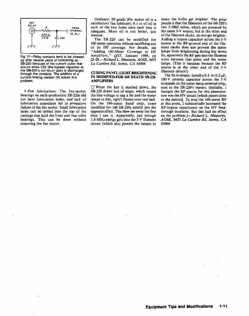
• Pitted contacts in the amplifier-controlrelay:A common problem with the SB-220is that it pits the contacts of the controlrelay in its associated transceiver afterseveral years' operation. The contactpitting is caused by the repeated shortcircuiting of C52 (the 0.02-~F bypasscapacitor at the SB-220's ANT RELAY),
which charges to + 115 V during receivingperiods. This problem can be solved byplacing a 200-0, Y2-W resistor in series withthe center pin of the ANT RELAY jack tolimit the capacitor discharge current (seeFig 17).
C7
RFCI
(B)
+HV
RSA
RAA
R2A
• The 3-5002s: If 3-500Zs possessingabove-average gain are used in a stockSB-220, the amplifier may occasionallyoscillate near 110 MHz. (This problem isnot unique to Heathkit" arnplifiers.) Thepresence of this condition is indicated by
R<A
C32 C32AFROM ---T T
BAND SWITCH,~TERMINAL 7
FROMFILAMENT
CHOKE
XCVR
~ DIN PLUG
CABLE 3 (ALC)ALC
- -----::: AMPANT
/~- RELAY
PHONO/
E ?=~NECTOR) CABLE 2
OLi
S
STANDBYI- ALUMINUM
1BOX
(A)
R3A
CABL
•(CONTR
IMPROVING THE HEATHKIT 8B-220AMPLIFIER
o The life of some of the components inthe SB-220 amplifier can be prolonged withsimple circuit modifications. Thesemodifications concern:
1-10 Chapter 1
•200ft
"i72W 1C02
ANTRELAY
FROM>t--.I\I'V'V-...-~ TER MINA L
10, RLl
Fig 17-Relay contacts tend to be chewedup after several years of controlling an88-220 because of the current pulse thatoccurs when C52 (the bypass capacitor atthe 88·220'5 ANT RELAY jack) is dischargedthrough the contacts. The addition of acurrent-limiting resistor (R) solves thisproblem.
• Fan lubrication: The fan-motorbearings on early-production SB-220s didnot have lubrication holes, and lack oflubrication sometimes led to prematurefailure of the fan motor. Small lubricationholes can be drilled into the top of thecastings that hold the front and rear oilitebearings. This can be done withoutremoving the fan motor.
Ordinary. SF-grade 20w motor oil is asatisfactory fan lubricant; 0.1 cc of oil ineach of the two holes once each year isadequate. More oil is not better, justmessier.
The SB-220 can be modified for160-meter operationwithout sacrificinganyof its HF coverage. For details, see"Adding 160-Meter Coverage to HFAmplifiers," QST, January 1989, pp23-28.-Richard L. Measures, AG6K, 6455La Cumbre sa, Somis, CA 93066
CURING PANEL-LIGHT BRIGHTENINGIN MODIFIED·FOR·I60 HEATH SB.220AMPLIFIERS
o When the key is mashed down, theSB-220 draws lots of amps, which causesthe line voltage to sag a bit and the meterlamps to dim, right?Fasten your seat belt.On the 160-meter band only, somemodified-for-l60 SB-220s exhibit just theopposite effect. This blew me away the firsttime I saw it. Apparently, just enough1.8-MHz energy gets into the 5-V filamentcircuit (wbich also powers the lamps) to
make the bulbs get brighter. The greatpuzzle is that tbe filaments of the SB-220'stwo 3-500Z tubes, which are powered bythe same 5-V source, but at the other endof the filament choke, do not get brighter.Adding a bypass capacitor across the 5-Vsource at the RF-ground end of the filament choke does not prevent the meterlamps from brigbtening during key downSo, apparently the RF gets into the filamentwires between that point and the meterlamps. (This is bananas because the RFsource is at the other end of the 5-Vfilament circuit!)
The fix is simple: Install a 0.1- to 0.2-~F,
l00-V ceramic capacitor across the 5-Vterminalson the meter-lampterminalstrip,next to the SB-220's meters. (Initially, Ithought the RF source for this phenomenon was the HV circuit [which passes closeto the meters]. To stop the 160-meter RFat this point, I substantially increased theRF-bypass capacitance on the HV feedthrough insulator. But this had no effecton the problem.)-Richard L. Measures,AG6K, 6455 La Cumbre sa. Somis, CA93066
EqUipment Tips and Modifications 1·11

FOUR CUTS MAKE CHANGINGIC-2AT BATTERY PACKS EASIER
o A good friend of mine and fellow ham,Russ. N8DMK, is blind and lacks the useof one arm. For 2-meter operation, hismainstay rig is an ICOM [C-2AT handheld transceiver. Problem: Each time the'2AT's battery pack died, Russ' motherhad to install a fresh battery for him. (Russ
.had tried many times, but could not getbattery and radio to line up just right. Histechnique looked good: Sitting down, heheld the transceiver betweenhis thighsandworked at pack and radio with his goodarm. Butsuccessat gettingthe pack to slidesmoothly onto the '2AT continued to eludehim.)
Ona recent visit,while wasI helping himpractice putting the battery pack 00, I gotan idea and asked Russ for the IC-lAT andbattery pack. After removing a few bits ofplastic with my pocketknife, [ handed thepair back to Russ and had him try again.Bingo! After a few tries, he slid the packright on! Even when he began the changeoveroperation with the packin a differentposition, Russ easily installed the batteryon the transceiver. He was overjoyed, andhis mother was thrilled with the accomplishment.
Fig 18-N8FCQ's removal of four bits ofplastic takes the frustration out of 1C-2ATbattery-pack changes for N8DMK. Themodification allows the metal shoe on thebattery pack (left) to contact the metal railon the transceiver (right) before the plasticrails interlock,
Fig 18 shows how to make the cuts.Remove just enough plastic to allow themating metal rails of the battery pack andtransceiver to catch before the plastic railsengage. This requires that the end of eachmetal rail be undercut slightly. I'vemodified my IC-2AT the same way: Now,I can change battery packs more easily,tool-Casey Nowakowski, N8FCQ. Berea,Ohio
OPERATE AND RECHARGE YOURICOM IC-2GAT HAND-HELD AT THESAME TIME
D This simple modification to an ICOMBP-7 or BP-70 battery pack allows you to
1-12 Chapter 1
ICOM
operate your [COM IC-2GAT from 13.8 Vand charge the battery pack at the sametime. You needn't buy power adapters orremove the battery from the radio; you caneven operate the radio while charging afully discharged battery pack! The partsrequired for this 30-minute modificationare two diodes (3-A rectifiers, preferablySchottky-barrier types for low forwardvoltage drop-IN5820, IN5821, IN5822and ECG586 are suitable), a piece ofmasking tape, a 3-inch piece of insulatedwire, and an inch or so of heat-shrinktubing. Keep a paper and pencil handy formaking notes. You'll also need a voltmeterto check out the modification before usingthe pack. Because accidental short circuitsare possible during the modificationprocess, modify only a fully dischargedpack. This modification probably voids thewarranty on the pack(s) you modify.
DisassemblyI. Remove the battery pack from the
radio.2. Mark the orientation of the charge
selector plate on the battery-pack bottomin case the plate comes loose. A piece oftape near the + side screw will do.
3. Remove only these fasteners: thepack's two bottom screws (+ and -), twoback screws (black) and four top-cornerscrews.
4. Remove the pack's plastic front cover.Do not remove the charge selector plate;pull it away from the back plastic cover andleave it stuck to the front cover.
5. Remove the pack's two dust caps (theyslide out).
6. Look at the space between the middleof the charger board and batteries to seehow much room you have to work in.
7. Carefully slide out the charger boardand pull it away from the case. Diagramits connections to the pack in case youbreak a wire during the modification.
Modification
8. Locate the + side lug terminal at thecenter of the component side of the chargerboard. (It's associated with the + screwatop the pack.)
9. Unsolder the + side lug terminal fromW9 and bend it 90 degrees away from theboard. Do not remove the + screw.
10. Bend and cut the leads of one of yourdiodes-let's call it Dl-to fit between W9and the bent-up lug terminal. (If necessary,you can extend the diode leads withinsulated wire to fit the diode elsewhere.)
I I. Solder DI's cathode (banded-end)lead to the + lug terminal, and its anodelead to W9.
12. Cut the anode lead from your seconddiode (D2) short and solder the 3-inch wireto it. Insulate this connection with heatshrink tubing.
13. Cut D2's cathode lead short andsolder it to the + lug terminal (along withDI's cathode lead).
14. Route the wire from D2 around thepack's charging-indicator LED and solderits free end to the center pin ( + ) of J2 (13.8V DC IN) on the copper-foil side of theboard. J2's center pin connects to the PCboard trace that goes to Dl2.
Checking It Out15. Measure the voltage between the
large metal plate ( - ) to the + screw atopthe battery pack. Measure the voltageacross the screw charging terminals on thepack's bottom. The voltage at both shouldequal the battery voltage.
16. Connect the battery to its wallcharger and plug in the charger. Measurethe voltage again at both places. The reading should equal half the battery voltage.Unplug the charger.
17. Apply 13.8 V to the 13.8VDC INjackand measure voltage on top of the pack.The reading should equal the input voltageminus the drop across DI and D2 (0.6 to1.0 V or so). Measure the voltage across thecharging terminals on the pack's bottom;this should be about 8.
18. If any of your measurements differsignificantly from the levels mentioned inSteps 15 through 17, recheck your work.Also, check to see if the wire fuse at W12has opened.
Reassembly
19. Reinstall the charger board in thecase.
20. Reinstall the dust caps. Note thatthey differ in size.
21. Dress the wires in the pack so theywill not be pinched when you close thepack, and recheck your work to make surea short circuit cannot occur.
22. Reinstall the plastic pack top,making sure the pack's charging-indicatorLED seats correctly.
23. Reinstall screws, starting with thoseat the back.
24. Repeat the measurements describedin Steps 15 through 17. If all's well, you'redone.
When using the modified battery pack,always power the radio from a supply lineprotected by a 2-A fuse.-JamesCleveland, N50NI, Temple, Texas
RESETIlNG THE CPU IN THE ICOMIC-mAT TRANSCEIVERo On a frosty morning, you shuffle intoyour station and pick up your hand-heldtransceiver to call someone; you turn on therig and hear the chatter. but the frequencydisplay is blank! What has happened is thaty~u've zapped the CPU's frequencydisplay memory. Don't worry-it's onlytemporary.
The IC-02AT's liquid-crystal display(LCD) panel is covered by a thin plasticmembrane as it comes from the factory.More often than not, this covering is lostduring normal use of the transceiver. If theplastic film is missing from your IC-02AT,do not touch the LCD panel if you canavoid it! Finger-delivered static electricitycan erase the frequency-display memory.In seasons of dry air, the chances of thishappening are particularly high.
If you have this problem with yourIC-02AT, the following procedure maysave you some money in getting theproblem solved. [Read this hint in itsentirety before working on your lC-02AT;if the reset procedure looks "a bit much"to you, don't try it-call ICOM instead.You may void your '02AT's warranty ifyou do this procedure yourself. If youdecide to reset your IC-02AT. rememberthat the procedure wipes its memoriesclean, so be sure to record this informationbeforehand if you won't be able to retrieveit from your memory.-AK7M]
1) In a clean, clear work area, removethe lC-D2AT.'s battery pack and place thetransceiver face down on the work surface.With a "jeweler's" Phillips-head screwdriver, remove the four side screws (two oneach side) and the screw near the top centerof the transceiver back. The four sidescrews are longer than the fifth screw; keepthis in mind so that you can reassemble thetransceiver correctly.
2) With a slightly larger Phillips-headscrewdriver, remove the screws that holdthe battery-pack latch plate to the '02AT.Underneath this plate, you'll find thebattery-pack latch spring and a plasticbutton; remove them also.
3) Carefully pry up the transceiver back;it serves as the transceiver's heat sink. Nearthe top of the exposed circuit board, you'llsee a shiny plate covered with a greasy,white substance. Do not remove thismaterial-it's thermally conductive grease.
4) Carefully push the chassis out of theplastic case from the bottom at the batterycontact point, or gently pull the chassisfrom the plastic case, being careful not totear the PC-board foil connection betweenthe two chassis halves. Open the sandwiched circuit board. In the half containing the IC-D2AT's lithium cell (about thesize of a nickel), you'll see, down and tothe left, the CPU reset switch. (Note:Although this reset procedure isn'tdescribed in the IC-02AT user's manual,the illustration on p 42 of the manual showsthe location of the reset switch.)
5) Attach a 12-V de power source to the12-V input port at the top ofthe '02AT andturn the transceiver on. Using a nonconductive wand, press the reset switch.
6) Turn off the IC-D2AT, disconnect the12-V de power source and reassemble thetransceiver. Now, the rig's CPU is reset to144.00 MHz, its display will function normally, and its memories must bereprogrammed.-Joseph J. Wavra, Jr,
WQ5M, 7017 NW Taylor Ave, Lawton,OK 73505
EASIER RESET FOR THE ICOMIC-02AT CPU
o There's a much simpler procedure forresetting the le-02AT CPU-one that doesnot require opening the radio. (1) Turn theradio off. (2) Press the FUNCTION button'Onthe side of the radio and hold it on, (3)Turn the radio on. That's it! The '02AT'sCPU is now reset, and all of the rig'smemories are set to their default value(144.000 MHz).-Pat Maturo, NIDYI, 233Harvester Rd, Orange, CT 06477
MORE ON RESETTING THE ICOMIC-02AT TRANSCEIVERMICROPROCESSOR
o About resetting the IC-02AT microcomputer. Holding the FUNCTION button inwhile turning the radio on will reset themicro only on radios with a serial numberabove 34,000. On IC-02ATs with lowerserial numbers, the internal reset buttonmust be pushed while the radio is poweredup. A special technique can make thiseasier: Remove the battery, and tip theradio straight back so you are looking atthe battery slide plate. Remove the upperleft screw from the plate. The reset buttonis about 3!4 inch in from the edge of thescrew hole.
Power the radio via the top-panel powerjack and turn it on. Insert a small, plastictuning tool, or a similar tool with a littlebend in the end, into the screw hole to pushthe reset button. You've achieved resetwhen you hear a tone from the radiospeaker. If reset is normal and the radio hasnot been modified for out-of-band operation, its display will show 140.000 and not144.00 as described by Maturo.
If the radio has been modified such thatits display "indicates 0.00, then you havesome work ahead or you. Enter 9.995 andpush the i button so the display shows10.00. Do this 13 more times to get to140 MHz.
One more tip: Some early '02ATs (in the8000 serial-number range) had an experimental reset circuit that allowed resetlike that in radios with serial numbersabove 34,000. The only way to find out ifyour IC-02AT is so equipped is to try it.(The circuitry that allows this could not beinstalled in other '02ATs for variousreasons.) An early IC-02AT can beequipped with the external reset feature(and other updated functions) by replacingits CPU with the later version, but ICOMwill not do this modification. Anothernote: The logic unit for radios with serialsabove 34,000 is laid out a bit differentlythan that of lower-number units; in radioswith serial numbers over 34,000, CPU lockup from static discharge is greatly reducedcompared to earlier units. Enjoy!-FredPalmer, WA5WZD, ICOM America, Inc,
3150 Premier Dr, Suite 126, Irving, TX75063
BACKUP-BATTERY REPLACEMENTFOR THE ICOM IC-27IH
D Removing the IC-27IH's RAM-boardlithium battery renders the radio inoperative because the '271H's operating programresides in RAM-board memory. RAMboards deprogrammed in this way must bereturned to ICOM for reprogramming.After having learned this the hard way, Irecommend practicing preventive RAMboard-maintenance every two or three yearsas follows: Pull the RAM board and solderanother new back-up cell in parallel withthe old one. Then clip out the old battery.Don't disconnect the old battery until thenew battery is safely soldered in.-John R.Gruenwald, K~BF, 1112 N 4th St, Sterling,CO 80751
Ina "Tech Talkfrom ICOM" ad (OST, February1986, pp 150-151), ICOM stated that "ICOMunits utilizing the lithium-cell-backed RAM concept include the IC-751 and IC-745 HF transceiver, the 1G-271A 2-meter base, IC-471AUHF base, IC·1271A 1.2·GHz base and ICR71A general coverage HF receiver." TheIC-271 and -471 were also available in hlqherpower versions (IC-271Hand -471H).-Ed.
IMMUNIZING THE ICOM IC-730AGAINST HIGH KEY-CONTACTRESISTANCE
D The IC-730 is a great no-frills HF transceiver, but it does have one weakness that'simportant to us old-timers who still insiston using bugs [semiautomatic speed keys-AK7M] for CW work. Because thelC-730's keying-circuit voltage is very low,the rig's RF circuitry is sensitive to the
+12 v(pin 2, rc-730 ACC pin 8, tc-730 ACC
'T.~-o----, 1"""'"
0'lN400l
KEY
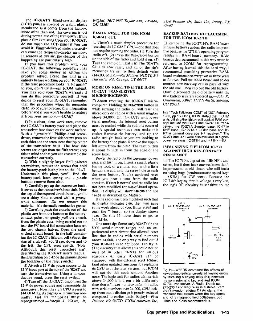
Fig 19-W6ERS overcame the effects ofkey-contact-resistance-related keying errorsby installing a keying relay (K1) betweenhis semiautomatic key and and ICOMIC~730 transceiver. A Radio Shack no.275-233 12-V reed relay is suitable. Verndidn't mention adding D1 (to clamp thetransient that occurs when the key opensand K1's magnetic field collapses), butHints and Kinks recommends it.
EqUipment Tips and Modifications 1·13

resistance of the closed keying circuit.Reports of missing dots and irregularkeying had me burnishing my bug's contacts every other day-or so it seemedeven though the transceiver's sidetonefollowed my keying faithfully.
An article in July 1982 QS7" addressesthe problem of IC-730 keying but doesn'treally help the bug user. My good friendMarv Juze, W6FGD, came to my rescue bypointing out that he had cured the sameproblem by keying his IC-730 with a reedrelay. Since implementing this suggestionas shown in Fi8 19, I've had no troublekeying my IC-730 properly (any irregularities may be attributed to my Lake Erieswing!). I've since learned that other localshave enjoyed the same success in keyingtheir IC-730s, so it seems worthwhile tospread the word.- "Uncle Vern" Howard,W6ERS, 733 Plymouth Wy, Burlingame,CA 94010
80. McClure, "Keying Improvementsto the ICOMIC-730," OST. Jul 1982, PP 23-27.
CONNECTING AN OLDMICROPHONE TO A NEWTRANSCEIVERo After acquiring an ICOM IC-735 transceiver, I found that a desk microphone wasdesirable for use at the home station in lieuof the hand mike that came with the rig.Sincemy Astatic D-I04 mike had servedmefaithfully for many years, I wanted to useit with the ICOM.
Examination of the rig's manual revealedthat the IC-735 was designed for lowimpedance (oO:¥ 600 0) microphones, and
that approximately 8 V dc is present on the'735's mike-audio line. Clearly, the D-104could not be connected to the rig withoutsome modification.
The circuit shown in Fig 20 solves thisproblem. All components within the shadeddashed lines are mounted on a small pieceof perf board and installed in the base ofthe microphone. The circuit's physicallayout is not critical.
This circuit has also been used successfully with an ICOM IC-761 transceiver.During testing with the '761, I found thatthe mike and PTT ground lines must notbe connected together, (If they are, a lowlevel switching noise will be present on thetransmitted signal.) Accordingly, the mikeground line must beisolated from the PTTground inside the microphone.
Pin I of the D-I04 microphone head isconnected to its enciosure(PIT ground) viaits mounting screw. To isolate the grounds,break the connection indicated in Fig 20.This can be accomplished by removing theconnector from the top of the microphonestand and rewiring pins I and 2 as shown.
This modification can probably be usedwith other transceivers having similarmicrophone-interface requirements. Besure. to verify the connector wiring anddouble check to ensure that the de supplyis not short-circuited. An ohmmeter checkis also advisable to verify that the twoground lines (pins 6 and 7 of the mike connector) are indeed isolated from each otherfor transceivers that require this. -DavidR. Fentem, KW4M, 704 Emerald ForestCir, Lawrenceville, GA 30244
SWITCH-SELECTABLE SUBAUDIBLETONES WITH THE ICOM UT-JOTONEGENERATORo I like to work to-meter repeaters withmy IC-735 transceiver, but some repeatersallow access only if my transmitted audioincludes a standard subaudible tone.?ICOM's UT-30 Programmable Tone Encoder Unit can be installed in the IC-735(and a number of other (COM radios) togenerate this signal. The UT-30allows youto solder-select only one of 38 differentsubaudible tones at a time. Here's how Imodified my UT-30 to allow switchselection of its tones.
Removeany solder-blob jumpers at padsPI through P6 on your UT-30. (NewUT-30s include only one-at P4, to set theboard to its 88.5-Hz factory default.) Next,wire a 6-inch-longpieceof seven-conductorribbon cable to the UT-30's generator ICas shown in Fig 21. Use a low-wattagesoldering iron (15W or so); a higher-poweriron may destroy the IC.
Next, decide where you'll install yourFREQUENCY switch unit. (I hot-glued mineto the bottom edge of my IC-735's front
9The Electronic Industries Association's table oftone-controlled squelch frequencies lists 42tones from 67.0 through 254.1 Hz, of which theUT-30 can generate all but tour (69.3, 206.5.229.1 and 254.1 Hz). During 1980, tho ARRLBoard of Directors adopted the 22 tones from86.5 through 179.9 Hz for voluntary incorporation Into to-meter repeater systems to providea uniform national system. See page 48 of JayMabey, editor, The ARRL Repeater Directory,1991·1992 edition(Newington:ARRL, 1991), formore information.-WJ1Z
1000 2
ElementCase
PTT Ground
Mike Ground
Mike Input
-<
7
6
+6 V
0.01 Ji-F
25 V
0.01 Ji-F
25 V
+
10 fLF
25 V
1 }-I-F or greater25 V
+
100 k 0
6800
MPF'102
G3
BreakThis
ConnedionL__.... .....---<.....--__-4.....>- .....J
3
r--I
ICase ,.~
Ground
0-104Element \}-~'1
PTT5
PTT
-.l-r o------------..:..J
a-Pin
Mike Connector
Fig 20-David Fentem connected his high-impedance 0·104 mike to an IC-735 and 1G-761 transceivers via this circuit, a JFET sourcefollower that acts as an impedance transformer. The resistors are Y4·W, carbon-film units; the components shown within the shadeddashed box are contained on a circuit board mounted in the mike base. With appropriate mike-plug connections, this circuit is applicableto other transceivers.
1-14 Chapter 1
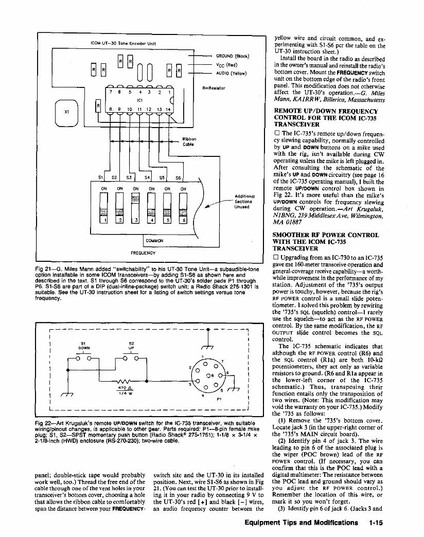
FREQUENCV
ICOM UT-30 Tone Encoder Unit
Fig 22-Art Krugaluk's remote UP/DOWN switch for the IC·735 transceiver, with suitablewiring/pinout changes, is applicable to other gear. Parts required: P1-8-pin female mikeplug; 81, 82-8P8T momentary push button (Radio 8hac~ 275-1751); '-'/8 x 3-1/4 x2-1/8-inch (HWD) enclosure (R8-270-230); two-wire cable,
yellow wire and circuit common, and experimenting with 51-S6 per the table on theUT-30 instruction sheet.)
Install the board in the radio as describedin the owner's manual and reinstallthe radio'sbottom COver. Mount the FREQUENCY switchunit on the bottom edge of the radio's frontpanel. This modification does not otherwiseaffect the liT-30's operation.-G. MilesMann. KAIRRW: Billerica, Massachusetts
REMOTE UP/DOWN FREQUENCYCONTROL FOR THE ICOM IC-735TRANSCEIVER
o The IC-735's remote up/down frequency slewing capability, normally controlledby UPand DOWN buttons on a mike usedwith the rig, isn't available during CWoperating unless the mike is left plugged in.After consulting the schematic of themike's UPand DOWN circuitry (see page 16of the lC-735 operating manual), I built theremote UP/OOWN control box shown inFig 22. It's more useful than the mike'sUP/DOWN controls for frequency slewingduring CW operation.-Art Krugaluk,N/BNG, 239 Midd/esex Ave, Wilmington,MA 0/887
SMOOTHER RF POWER CONTROLWITH THE ICOM IC-735TRANSCEIVER
o Upgrading from an IC-730 to an IC-735gave me 160-metertransceive operation andgeneral-coverage receive capability-a worthwhile improvementin the performance of mystation. Adjustment of the '735's outputpower is touchy, however, because the rig'sRF POWER control is a small slide potentiometer. ] solved this problem by rewiringthe '735's 5QL (squelch) control-I rarelyuse the squelch-to act as the RF POWER
control. By the same modification, the RF
OUTPUT slide control becomes the SQLcontrol.
The IC-735 schematic indicates thatalthough the RF POWER control (R6) andthe SQL control (RIa) are both lO-kOpotentiometers, they act only as variableresistors to ground. (R6 and RIa appear inthe lower-left corner of the IC-735schematic.] Thus, transposing theirfunction entails only the transposition oftwo wires. (Note: This modification mayvoid the warranty on your IC.735.) Modifythe '735 as follows:
(1) Remove the '735's bottom cover.Locate jack 3 (in the upper-right corner ofthe '735's MAIN circuit board).
(2) Identify pin 4 of jack 3. The wireleading to pin 6 of the associated plug isthe wiper (POC brown) lead of the RFPOWER control. (If necessary, you canconfirm that this is the POC lead with adigital multimeter: The resistance betweenthe POC lead and ground should vary asyou adjust the RF POWER control.)Remember the location of this wire, ormark it so you won't forget.
(3) Identify pin 6 of jack 6. (Jacks 3 and
AdditionalSectionsUnused
(Black)
d)
Vellow)
2
switch site and the UT-30 in its installedposition. Next, wire 81-86 as shown in Fig21. (You can test the UT-30 prior to installing it in your radio by connecting 9 V tothe UT-30's red [+ 1and black [-I wires,an audio frequency counter between the
GGGROUND
GG 00 GGVCC (Re
AUDIO (
~~ - R=Resistor7 6 5 4 3 2 ,
[J SIC1 (
B 9 10 11 12 13 14
I\..
RibbonCable
5,r 52 5~ ~-:l sa ,ON ON ON ON ON ON
~ g~ g~ ~'~-
ICOMMON
~---------------------1-----'I 51 52
I ~ ~IIIIII ~I 1/4 W 4
I P1 1L J
Fig 21-G. Miles Mann added "switchability" to his UT-30 Tone Unit-a subaudible-tonsoption installable in some ICOM transceivers-by adding 81-86 as shown here anddescribed in the text. 81 through 86 correspond to the UT-30's solder pads P1 throughP6. 81-86 are part of a DIP (dual·inline-package) switch unit; a Radio 8hack 275-1301 issuitable. 8ee the UT-30 instruction sheet for a listing of switch settings versus tonefrequency.
panel; double-stick tape would probablywork well, too.) Thread the free end of thecable through one of the vent holes in yourtransceiver's bottom cover, choosing a holethat allows the ribbon cable to comfortablyspan the distance betweenyour FREQUENCY-
Equipment Tips and Modifications 1·15

Fig 23-Transposition of tha 1C-73S's poeand SOll wires for smoother RF-outputpowercontrol. This modification exchangesthe functions of the '735'8 AF POWER andSal controls. See text.
o I'm sure there must be other fatfingered harns out there who are proud butuncomfortable owners of IC-735s: proudbecause they own a '735, anduncomfortable when trying to use the tinyslide controls under the rig's front-paneltrapdoor. The door can be removed easily:Just flip it to the horizontal position andpull.
1-18 Chapter 1
"0J2
aa n
240.n.
OdBo~---~o Ss
82n
"0JI
PUTTING VARIABLE-BANDWIDTHTUNING BACK INTO LATE-MODEL!COM IC-75IA TRANSCEIVERS
o When I bought my ICOM IC-75IA inMarch 1990, I was puzzled because thelabel for one of its front-panel controlsdiffers from that on earlier-modelIC-751As. Older IC-75 lAs had a variable:bandwidth-tuning (PBTIO) control in thelower-right front-panel corner. On my rig,this control is labeled IFSHIFT, and a fullycounterclockwise IF SHIFT OFFposition hasbeen added. Experimenting, I found thatactivating IF shift noticeably degraded thetransceiver's selectivity and dynamic range.I determined that turning on the IF shiftbypasses the IC-751A's 9-MHz IF filter andleaves only a 455-kHz IF filter in line.
An extremely simple modification canrestore the function of this control to VBTrather than IF shift, and allow the 9-MHz
1OVarlable·bandwldth tuning is referredto aspassblind tuning or psron ICOM equipment.-Ecl.
if Your IC-745 Seems to Be Lacking inReceiver Gain. . .o My IC-745 transceiver suffered fromsporadic, slight changes in overall receivergain. Moving the radio and tapping itscomponents affected the problem but didnot reveal its cause, and no repeatableeffects were found. I did notice, however,that prodding the wiring around the '745'sMain and IF circuit boards had the mosteffect.
I discovered the cause of the problem byaccident. While realigning the receiver, Ifound that R2, the '745's 22-klJ TOTALGAIN trimmer potentiometer, had been setalmost to its "no gain" point. Very slightreadjustment of R2 during realignmentsolved the gain-variation problem, andno further abnormal gain shifts haveoccurred.-Earle Grandison, K6WS,11657Gladstone Cir, Fountain Valley, CA92708
Fig 25-Earle GrandIson took advantage ofthe 1G-745's inclusion of RECEIVER INPUT andRECEIVE ANTENNA OUTPUT jacks to add thisswitchable 20-dB RF attenuator. The circuitis built In a small aluminum box; phonoplug-equipped coaxial cable. connect thebox to the 1C-745, The resistors arecarbon-film or -composition units. J1 andJ2, phono Jacks, are labeled, I/O becausethe attenuator is bilatera/-elther jack canserve as input or output.
(B)
Fig 24-Larry Murdoch increases the"grabability" of his IC-735's slide controlswith bobby pins modified as shown here.
Here's how I extended the IC-735's slidecontrols for easier operation. (Theseinstructions are for one control.) Cut abobby pin so that its loop end is about ~inch long (Fig 24A). Slip small-diameterheat-shrink tubing over the pin ends asshown in Fig 24B. Shrink the tubing. Next,use a small screwdriver to spread thebobby-pin ends and slip the modified pinover one of the IC-735's slide controls.Push the control extender into place untilit protrudes for 5/16 inch or so.
This idea works well for me; I put theseextenders on the IC-735 slide controls I usemost: RF POWER, VOX DELAY, and MIC
GAIN. Yes, they are removable I-Larry D.Murdoch, K6AA W, 14370Brian Rd, RedBluff, CA 96080
TWO NOTES ON THE ICOM IC-745TRANSCEIVER
A Switchable 20-dB RF A lIenuatoro The IC-745 does not include an RFattenuator, but one can be added easily.The rear panel of the '745 holds connectorsfor numerous accessory functions. Theseinclude an SO-239 ANTENNA socket andphono jacks for RECEIVER INPUT andRECEIVER ANTENNA OUTPUT. The IC-745'sTR relay switches the SO-239 between thetransmitter output (inside the radio) and theRECEIVER ANTENNA OUTPUT jack (on therear panel). Normally, a shielded jumpercable connects the RECEIVER INPUT andRECEIVER ANTENNA OUTPUT jacks forsingle-antenna, transceive operation. Thisjumper offers the perfect access point toinstall an RF attenuator without defacingthe transceiver.
To construct a 20-dB attenuator, wireand install the circuit shown in Fig 25. Thissimple addition allows selection of 0- and20-dB attenuation values at the flip of aswitch.
i 3l4"j; -"'OA J~
CUT OFFAND
DISCARD
--j "'0" IHEAT- ...'1G===~SH.'NK~i JTUelNG r- 7/16 "-,
(A)
SOll a
poe a
SQlL
xpoe I
poc
SOLL 1
poe 1 sou, a
SOLLIG POC 2
SOLDERED ANDTAPEO CONNECTIONS
ICI
IBI
IAI
6 are about 2 inches apart on the MAINboard.) The wire leading to pin I of theassociated plug is the wiper (SQLL white)lead of the SQL control. (If necessary, youcan confirm that this is the SQLL lead witha digital rnultimeter: The resistance betweenthe SQLL lead and ground should vary asyou adjust the SQL control.) Rememberthe location of this wire, or mark it so youwon't forget.
(4) Follow the pac and SQLL wiresback into the cable harness to a point wherethey are adjacent to each other. Cut thepac wire and strip the cut ends. Cut theSQLL wire and strip the cut ends.
(5) Transpose the wires as shown in Fig23, and reconnect them by soldering themtogether. Tape the connections withelectrician's tape and reassemble theIC-735. (As an alternative to electrician'stape, you can use heat-shrink tubing toinsulate the connections. If you choose todo this, slip the tubing over the wiresbetween steps 4 and 5, and shrink it afteryou solder the connections.)
That's it! Now, the SQL ring around theAF gain control adjusts the IC-735's RFoutput power-smoothly.-Ted O'Connell,NS6H, Walnut Creek, California
CONTROL EXTENSIONS FOR THEICOM IC-73S TRANSCEIVER

0 0 0 0 0 0 0 0 0
8 :il 0 0 0 0 0 00 "' "' 0 "' 0
N r ., I + " "N
I +Distance from IF" Center (Hz)
Fig 26-Variable-bandwidth tuning, when implemented in current transceivers by electronicallymov~ng the passband of one filter relative to the stationary passband of another filter, can alter areceiver's blowby and dynamic-range characteristics even though cascaded IF filters are present.Offsetting the filters' passbands creates two zones (Zone 1 and Zone 2) in which only onefilter provides most of the system's ultimate attenuation. Strong signals that fall within Zone 2-the zone in which the Filter 2's stopband provides the only defense against nearby signals-may significantly degrade the receiver's dynamic range. (The size and shape of"the zonesand the numeric values for filter bandwidths, net bandwidth and distance from IF center, show~here are for illustration only. The zone shapes and filterlnet bandwidths you encounter dependon the VBT-control setting, and the design and construction of your transceiver and its IF filters.The net passband's top is lower than that of both filter curves because filter insertion losses addin a cascaded-filter system.)
filter to remain in the signal path. Orientthe radio so its front panel faces you andtake off its top. Locate the single black wirethat is pushed onto terminal Jl7 on themain board. (117 is approximately Y4 inchto the left of the left rear corner of FL-SO,the IC-75IA's 9-MHz SSB filter.) Pull thiswire off the terminal and tape it aside soit can't short to anything. That's all thereis to it!
Now, the IC-75IA's IF SHIFT controlfunctions as a variable-bandwidth tuningcontrol, and since you lose no receiver performance when it is active, you can leavethe IFSHIFT control (now an IF shiftlVBTcontrol) at its center detent all the time.You needn't use the IF SHIFT OFF positionat all.-John Pelham, WIJA, 1185BendCreek Trail, Suwanee, GA 30174
WJIZ: Figs 8 and 9, and their supporting text,in G. Collins and D. Newkirk, "TransceiverFeatures That Help You Beat Interference,"OST,Mar1991, pp 16-21,can helpexplainwhyturning on the 1C-751A's IFshift degrades thetransceiver's ultimate attenuation and dynamicrange. Fig 9 in that article shows a method ofimplementingVBT by placinga second IFfilterat the output of a simple IF-shift circuit (Fig 8in the article cited). Reverse this process-thatis, bypass the filter just added to achieveVBT-and the system reverts to IF shift.
Placing a second filter at the input of the IFshift circuit also results in VBT-and this is, ineffect, howICOM does it(inat least the 1C-751A,'761 and '765). Convertingsuch a VBT systemto IF shift requires that the first filter in the chainbe bypassed. The potential snag in thisarrangement is that bypassing the first filter subjectsthe circuitry between the first filter's output andthe second filter's input to signals otherwiseattenuated by the first filter's stopband. In1C-751As (as evidenced by John Pelham'sobservation) and IC-l6SS (as conclusivelyproven in the ARRL Lab, and enumerated inTable 2 of December 1990 osr« iC·765Product Review), enabling IF shift by bypassing the first of two VaT-system filters may significantly compromise the system's close-indynamic range. (The system's ultimate attenuation SUfferswhichever filter you bypass.)
John Pelham's statement that VBT does notcompromise receiver performance is necessarily true only when the VaT control is set forthe maximum bandwidth afforded by the filtersinvolved. See this column's Fig 26. Adjustingsuch a VBT system for narrower-thanmaximum net bandwidth may cause at leastthree effects:
1. Offsetting the passbands creates twozones (Zone 1 and Zone 2 in Fig 26) in whichonly one filter's stopband provides thesystem's ultimate attenuation. Depending onthe radio's design, construction and filters,blowby from signals within these zones mayrange from inaudible to objectionable.
2. Strong signals falling in one of these twozones-the zone in which the second filter'sstopband provides the only defense againstnearby signals (Zone 2)-may cause blockingor significantly degrade the receiver's dynamicrange.
3. In a two-filter VBT system using practicalfilters-that is, filters that have a shape factorgreater than 1-offsetting the filter passbandsunavoidably degrades the system's skirtselectivity. This is so because the filter's skirtslopes maximally reinforce each other onlywhen both filters' passbands are superimposed
Zone 1
filter 1 Possband --1----..F"lIter 2 Passband
as closely as possible. Offsetting the filters'passbands to create a narrower net passbandforces one filter to provide all or most of thesystem's higher-frequency skirt selectivity· theother filter provides all or most of the syst~m'slower-frequency skirt selectivity. In a VaTsystem based Ontwo good-ta-excellent filters,this effect is not serious. If one of the system'sfilters has significantly poorer skirt selectivitythan the other, however, one side of thenarrower-than-maximum net passband willexhibit noticeably poorer skirt selectivity thanthe other. (In Fig 26, both filter curves, andtherefore both sides of the net passband, areessentially identical, but such is usually not thecase in practlce.)
Although VBT is a valuable transceiverfeature, it doesn't provide something fornothing. Cascaded filters work best when theirselectivity characteristics match closely andtheir passbands are closely superimposed. Offsetting cascaded-filter passbands for VSTcompromises that performance to some-
o hopefully, a small-degree in exchange forvariable bandwidth. In today's transceivers, theselectivity flexibility gained is generally wellworth that small compromise.
VARIABLE·BANDWIDTH TUNING FORTHE ICOM IC·765 TRANSCEIVERo As mentioned in Product Review forDecember 1990,11 The IC-765 transceiver
11M. Wilson, "The ICOM IC-765 MF/HF Transceiver," J. Healy, conductor, Product aevrewOST, Dec 1990, pp 52-55. '
--\,,Zone 2 ,,,,,,,
\\
does not include the variable-bandwidthtuning (VBT) feature present in theIC-761. 12 You can change the '765's IFshift to VBT by adding two diodes and anRF choke, or add VBT and gain the abilityto select between IF shift and VBT byadding two diodes, an RF choke and a subminiature switch (see Fig 27). Either way,no holes need be drilled in the IC-765, nosoldering need be done on any of the '765'scircuit boards, and the modification isentirely reversible.'! (Note, however, thatthis modification may void your IC-765'swarranty.) Here's how to do it; please readand familiarize yourself with all of thesesteps before proceeding:
1. Disconnect all external leads to theIC-765 including antenna, power and so on.
2. Remove the top and bottom covers asdescribed on page 41 of the lC-765 Instruction Manual.
12()n ICOMequipment, variable-bandwidth tunif19is referred to as passband tuning or PBT.-Ed.
»smce developing this modification, I havebecome aware that others have Implementedvarious versions of the same basic Idea. Forexample, Gerd Hen/'es, W2ISB, has describedan approach that a lows selection between IFshift and VBT with the IC-765's IF SHIFT button,a la the IC-761. Gerd's modification requiressoldering and desoldering on the '765's MainUnit board. For details, write him at 4065Pawnee Dr, Liverpool, NY 13090. Be sure toenclosean SASE. TheARRLandQSTin nowaywarrant this offer.
Equipment Tips and Modifications 1·17

toQ43
Fig 27-Rich Guski changed his IC-765's IF-shift feature to variable-bandwidth tuning byadding three parts (01, 02 and L1) and one wire (W1). Adding one more part (81) andanother wire (W2) allows you to select between STOCK '765 and YBT. The remaining partdesignators refer to IC-765 components; only IC·765 components directly relevant to themodification are shown here. See text.
+8 VatGray Wire
of P31in J15
Stock'765
from~o----r-t +8 V11 ) S1 VBT 'I - (see cbove )
Wl W2
VBT/Stock '765 Option
L10.5 to1 mH
12. Connect a subminiature SPST switch(51) across the free ends of WI and W2.When the IC-765's IF SHIFT button ispressed, closingSI selectsVBT, and openingSI selects the IC-765's stock IF shift switching. I used a small slide switch for SI.mounting it under one of the four screwsthat support the control board located underthe radio's top-cover hatch.
I highly recommend this modification. Itmakes an already fine radio significantlybetter.-Rich Guski, KC2MK, RD 2 Box54/, Red Hook, NY /257/
Q38
02
01. 02 -lN4148 or lN914
~W31
01
R200
064
063
14Table 2 of the December 1990 1C-765 reviewsuggests that the '765's IF-shiftcapability is bestleft unusedin thepresenceof strongsignalsandheavy interference.-Ed.
between VBT and IF shift, go to the nextstep (Even if you don't intend to use IFshift," consider adding this feature. Withit, you'll be able to compare how VBT andIF shift function.)
11. Substitute an IS-inch length ofhookup wire for the 8-inch length of wire
. (W I) in Step 8. Connect a second 18-inchlong length of hookup wire (W2) into P31.
3. With the radio upside down and itsfront toward you, locate wire 31 (W31) onthe '765's Main Unit board. W31 is brownand about 5 inches long. It connects the baseof transistor Q38 to the cathode of diodeD63. These components are in the right.middle area of the Main Unit board abovethe upper-right end of the 9-MHz-crystalfilter group.
4. Cut W31 at a point about 1 inch fromits Q38 end. Carefully strip 1/8 inch ofinsulation from both wire ends.
5. Install a switching diode (Radio Shack276-1122, IN4148, IN914 or equiv) acrossthe W31 cut, cathode toward Q38. (Hereafter, I'll refer to this diode as OJ.)
6. Connect the cathode lead of a secondswitching diode (hereafter 02) to thecathode end of OJ.
7. Solder one lead of a subminiature 0.5to l-rnH choke (hereafter Ll) to the anodeend of 02.
8. Solder an 8-inch length of no. 18 hookup wire (hereafter WI) to the free end of Ll.
9. Locate J15 on the Main Unit (on thefar left of the Main Unit board. about halfway between the radio's front and rearpanels; look for the large 3/ stamped on theside of its associated plug, P3J.)
10. Connect WI into P31 where the graywire exits P31. This P31 terminal serves asan 8-volt source (for switching purposes)when the IC-765 is in receive mode.Soldering is neither necessary nor desirablefor this step. Tape the stuck-in wire toadjacent wires to keep it firmly in place. Atthis point, you've converted the IC-765's IFshift to VBT. If this is all you want to do,stop here, reassemble your IC-765, andenjoy using VBT instead of IF shift. (Pushyour IC-765's IF SHIFT button to selectVBT.) If you want to be able to switch
1-18 Chapter 1

Kenwood
Fig 28-Kurt Hunter and Martin Salabes connect a Kenwood 88-8 pan-display adapter toa generic oscilloscope as shown here. some Kenwood transceivers include a jack thatcarries the 8.83-MHz IF signal necessary to drive the 8S-8; see the text for one means ofobtaining this signal from a TS-430S.
Using the SM-220 with the TS-940S Transceiver
Used for Band Scope operation with theTS-940S, the SM-220 sometimes displaysghost signals that are apparently verystrong-but which are inaudible in theTS-94OS! (As a result. the many strongshortwave-broadcast signals in the IS-MHzrange severely compromised the display'susefulness at 14 MHz.) Turning on theTS-940's loo-kHz calibrator generatedmarkers every 100 kHz and a ghost signalabout 10 kHz lower than each legitimatemarker. Investigation revealed that each ofthese ghosts was associated with a strongsignal 910 kHz higher than the transceiveroperating frequency. (I verified this witha signal generator.)
The TS-940's IF1 output is heavilydamped by a 56-0 resistor across the signalsource connected to the IF1 jack. Thebandwidth of the '94O's 45.05-MHz, firstIF amplifier is so wide that signals significantly far from the IF center are presentat the IF1 jack. (A filter later in theTS-940's signal path removes these so theydo not affect reception of desired signalswith the TS-940S. They appear in theTS-940's IF1 output, however, and causeimage responses [910kHz removed fromthe desired signal] when heterodyned to455 kHz [2 X 455 = 910] in the SM-220.)
The heavy loading on the IF1 line in the'940 severely damps the input tuned circuit
+11 V
SWEEP SELECT
Sawtooth SweepSiQnol Input
-12 V
(solder to pins)
~~~=3--i teScopeVertIcalInput
P202
..;;.•
BS-B
3 GND 2
NC 2 3Ne Peak for rna..
NCscope .deflection
4MARKERSW
(SOlder to pins)5
6
7
NARROW WIDE 8• •CENTER ADJ9
transceiverareusuallyusablefor littlemorethanchecking band activity and noting the relativeamplitude of signals on a small segment of anamateur band. Laboratory-quality panoramicdisplays called spectrum analyzers are usuallycalibrated accurately enough to measurerelative and absolute amplitude and frequencycharacteristics of displayed signals over a widerange of frequency spans. Chapter 25 of The1990 ARRL Handbook, Test Equipment andMeasurements, covers spectrum analyzers indetail.-AK7M
servations and several suggested solutions.
Using the SM-220 with the TS-830S Transceiver
Plugging the SM-220 cable into theTS-S30's IF1 IF-output jack causes allreceived-signal levels to drop by about3 dB. This occurs because connecting the'220 increases the load on the TS-S30'sS.S3-MHz IF amplifier. I solved thisproblem by installing a 510-0 resistor inseries with the center conductor of thecoaxial cable between the TS-S30S and theSM-220. Install the resistor inside theTS-830S as follows: Remove the transceiver's top cover. Unsolder the coax leadto the center pin of the '8305 rear-panellF1jack. Install the resistor between the connector pin and the cable center conductor.Reinstall the TS-S30's top cover. I foundthat this change does not detune the IFtransformer associated with IF1 (L2 on theTS-S30's IF Unit).
USING THE KENWOOD BS-8PANORAMIC-DISPLAY MODULEWITH GENERIC OSCILLOSCOPES
D You can use your oscilloscope as apanoramic display in conjunction withKenwood transceivers that have 8.83-MHzintermediate frequencies (IFs) by teamingthe scope with a Kenwood BS-Span-displaymodule, generally available at Kenwoodham-radio-equipment dealers for about$110."
Connect the adapter as shown in Fig 28.The BS-S requires 11 V de (negativeground) and 12 V de (positive ground);these voltages may be obtainable from thescope if it's solid state. Pick up the transceiver's S.S3-MHz IF signal at the input endof the receiver IF stages. (In the KenwoodTS-43OS transceiver, this signal is accessibleat jack 6 on the 430's RF board.) Feed theBS-S's output (labeled 10 ScopeVortl08llnputin Fig 2S)into the scope's vertical (Y) input.
Finding a tap to obtain the oscilloscope'ssawtooth sweep signal may take a littleexperimentation. This signal .should beavailable at the scope's horizontal-outputdriver stage, or at the output of the scope'ssawtooth-oscillator buffer amplifier.
Adjust the scope's vertical sensitivity;0.1 V/div is sufficient. Use the slowestsweep speed that does not produce noticeable display flicker .-Kurt E. Hunter,WB3AGC, Box 351 Highland Rd, Orefield,PA 18069,and Martin K. Salabes, K3CSV,1631 Sweetland St, Nokomis, FL 34275
16A panoramic dIsplay (Band Scope in SM-220terminology) is a cathode-ray-tube (CRT)displayof receivedsignals in terms of frequency(on theX, or horizontal axis, of the display) andamplitude (on the Y, or vertical axis, of thedisplay). Panoramic displays intended for onthe-air use-such as the SM-220 in its BandScope mode-are generally arranged so thatthe receiver's operating frequency(thefrequency shown on the receiver's dIgital display)appears at the exact center of the X axis, withsignals below and above the operatingfrequency appearing to the left and right of theoperating frequency, respectively. Generalpurpose panoramic displays capable of beinghooked to an Amateur Radio receiver or
15This hint is not for beginners; it requiresdigginginto the innards of an oscilloscope-danger,high voltage/-and, in some cases, into thecircuitry of the transceiverthat drives the B$-8.Hints and Kinks recommends that you obtain,and refer to, servicemanualsand/orschematicdiagramsof the BS..a, and your transceiverandoscilloscope, before putting this hint Intopractice. The BS·8 schematic appears indocumentation for Kenwood's SM-220StationMonitor.-AK7M
NOTES ON BAND-SCOPEOPERATION WITH THE KENWOODSM-220 STATION MONITORo I enjoy using the SM-220 stationmonitor very much. I have, however,found a few rough edges in its operationas a panoramic display." Here are my ob-
Equipment Tips and Modifications 1-19

(T201) in the SM-220, lowering its Q andmaking it too broad-band. The solution:Install a 24- or 27-pF capacitor in serieswith the center conductor of IF1 cablebetween the TS-940 and SM-220. Next,retune T201 (see the SM-220 manual) topeak a calibrator marker near the display'scenter frequency. Use a plastic or woodentuning tool. (Because the slot in T201 's coreis tiny. you'll probably need to shape thetuning tool to a small, chisel point about1/16 inch wide.) With the capacitor inplace, T201's peak is considerably sharpert.han in an unmodified SM-220, but is sufficiently wide to allow proper display in theSM-220's ± lOO-kHz mode.
Modified in this way, my SM-220 displays ghosts of only the very strongestI5-MHz stations. Ghosts that occurred onother bands, and those produced by theTS-940's lOO-kHzcalibrator, are unnoticeable or unobjectionable in the presence ofnormal band noise.
Some further comments: Although a 24~
to 27-pF capacitor should suffice to reducethe loading on T20l, you may need to experiment with the value of this capacitor.Too much capacitance fails to eliminate the
.images; too little capacitance reduces theamplitude of the displayed signal.
I suspect that further improvement ofthis image-reduction fix could be made byreplacing the TS~940's on-board IF1damping resistor with one of a higherresistance. When my TS-940S is out ofwarranty, I'll probably try this. Meanwhile,I'd appreciate hearing from anyone whotries this.-Charles J. Michaels, W7XC.13431 N 24th Ave, Phoenix, AZ 85029
AK7M: Because the SM-220 contains a CRTand operates from the 120~V ac mains,portions of its circuitry operate at dangerousac and dc levels. Don't attempt to modify apluqqed-In SM~220, don't work on anunplugged SM-220 until its power-supply filtercapacitors have discharged, and make "live"adjustments only after taking the precautionsspecified by Kenwood in the SM-220documentation.
MORE SM·220 MODIFICATIONS
Automatic Trace Shift During Band ScopeOperationD The SM-220's display is most useful inits Osc/RTTY and Moni/Trap modeswhen centered vertically on the displaygraticule. In the Band Scope (panoramicadapter) mode, though. the display is moreuseful when repositioned two scale divisions below center. This provides moreroom for display of signal amplitude. Aone-resistor modification can provide thisshift-when you set the SM-220's FUNCTION switch to BAND SCOPE, or automatically if you've modified your SM-220 as perWade A. Calvert's "Automatic TR Switching for the Kenwood SM~220 MonitorScope" (QST, Nov 1988, pp 24-27).
See Fig 29. On the foil side of theSM-220's main PC board, solder one leadof a I-kG, !;4~W resistor to the junction of
1·20 Chapter 1
BoardEd.....
Fig 29-Eldad Senary added Band Scopedisplay shift to his SM~220 Station Monitorby installing a 1-kO, 1j4~W resistor on theSM-220's main PC board as shown here.See text.
RI26 (220 II) and VRlO3 (500 II, the V.POScontrol). Solder the other resistor lead topin 1 of P103. To avoid short circuits. slipinsulating tubing over the resistor leads before soldering.Curing Horizontal Shrinkage of the BandScope Display
The SM-220's horizontal trace shrinkswhen its SYNCIMKR switch is set to INT/OFF.
This shrinkage does not occur whenSYNC/MKR is pressed to EXTtON, but thenthe Band Scope marker comes on, maskingsignals at the display's center.
To solve this problem, remove theSM-220's top cover. The SYNCtMKR switchis a DPDT unit. The side of the switch withtwo wires controls the marker; the otherside of the switch-c-with three wiresswitches the sync. Disconnect the two outerwires on the sync side of the switch, transpose them, and reconnect them in theirtransposed positions. Now, you can enjoyshrink-free Band Scope operation with theSM-220. With this modification in place,the functions of the SYNC/MKR switch areEXTtOFF (out) and tNTtON (in).
Calibrating the SM-220's Band-ScopeDisplay
If you adjust the SM-220's ±20 kHzscan width to ± 25 kHz, you'll have a veryconvenient 5 kHz/div scan that simplifiesestimation of signal spacing. See pp 18-19of the SM-220 operating manual, or p 22of the SM-220 service manual, for how toadjust the SM-220's scan width and displaycenter frequency. The .± 20 kHz scan widthcan be adjusted to ± 25 kHz by adjustingthe ± 100 kHz control (fC201). (This doesnot much degrade the limited accuracy ofthe ± 100 kHz range.) Alternatively, installing a 330-kll, \1,-W resistor (this valuemay require experimentation) in parallelwith R245 (68 kll) on the BS-8 (or BS-5)module should accomplish the same thing.
Quieting an SM-220 Equipped withWA9EZY's Automatic TR MOdification
After installing WA9EZY's SM-220-TR-
switching modification (QST, Nov 1988, pp24-27), f quickly became annoyed with itsrelay noise. I use VOX most of the time,and a relay clicking on every TR transitionis an unwelcome side effect to a very niceoperating convenience. The solution is simple: I replaced the WA9EZY-modificationrelay with a reed relay.
If you cannot find a 3PDT reed relay (Icouldn't), don't despair. You can use threeSPDT, or one DPDT and one SPDT, ortwo DPDT, relays. If you don't have thesein your junk box, get them from DigiKey,~ Radio Shack or other suppliers. Thecombined coil resistance of the added relaysshould be 200 II or more (I2-V, SPDT reedrelays usually have coil resistances- aroundI kll; 12-V, DPDT reed relays usually havecoil resistances around 500 0).
Twelve-volt reed relays generally pull inat about 8 V and up, so you can connecttwo 12-V, or three 6-V, relays in series andsupply their solenoids from the unfiltered+ 20 V available at the positive terminal ofC143, a 220-pF, 25-V electrolytic capacitor in the SM-220's low-voltage powersupply,
One of two approaches can be taken toquiet the SM-220's built-in relay, RLlOl:
(I) Install a 180-11, \I,-W resistor in series with, and a 100-pF, IO-V electrolyticcapacitor in parallel with, RLlOI's coil.You can install these components under thePC board and near the relay-the resistor,by cutting the copper trace between D 101and the RLIOI solenoid, and soldering theresistor across the cut; the capacitor, by installing it across the solenoid-terminal pads,with its negative lead to ground.
(2) If you want to silence RLIOI completely, replace it with a I2-V, SPDT reedrelay. You can remove RLIOI from theboard by desoldering its leads with desoldering braid and working it loose fromthe board. There's enough space underneath the circuit board for a reed-relayRLIOI substitute.-Eldad Benary, NZ2F.7510 George Sickles Rd, Saugerties, NY12477
AK7M: See the caution at the end of W7XC'sSM~220 item, above.
RF FEEDBACK IN THE KENWOODTS·130S
D After using my TS-130S mobile for anextended period of time, the followingproblems suddenly arose: In CW, the transceiver continued to emit a carrier even afterthe key had been released. In the SSBmode, the transmitter went into oscillationas soon as modulation was applied,producing a continuous output signal evenwhen modulation had ceased. Theseproblems occurred on all bands above7 MHz-even though the transceiver'spower-supply voltage, and the SWR on theantenna feed line, were within acceptablelimits.
Because the radio had been subjected tovibration in mobile operation, I suspected

Fig 30-Dave Miller's memory button guard consists of a single piece of 5/32-inch-thickwood veneer. The dimensions shown may need to be changed to fit your situation.
F. Miller, K9POX, 7462LawlerA ve, Niles,IL 60648
A NARROW RTTY FILTER FOR THEKENWOOD TS·430S TRANSCEIVER
D For owners of TS-430Stransceivers thatinclude YK-88CN 27Q-Hz CW filters: Connecting pins I and 2 of connector 27 on the430's IF board with a short piece of solidwire (no. 22 is suitable) causes theYK-88CN to be selected in the transceiver's"narrow SSB" modes. When used for LSBreception, the filter is centered on the standard high RTTY tones for 170-Hz shift(2125 Hz mark and 2295 Hz space) andworks great. The only drawback to thismodification is that the 270-Hz filterdoesn't work in the USB mode (necessaryfor AMTOR operation) unless the IFSHIFTcontrol is turned clockwise as far as it cango-and then it passes only the mark toneand attenuates the space tone.-KennethO. Flint, N7IMR, 3600 Data Dr #58,Rancho Cordova, CA 95670
CW-PITCH·CONTROLMODIFICATION FOR THE KENWOODTS-440S TRANSCEIVERD Somenewertransceiver models havea CWpitch control-a control that changes thepitch of received CW signals while keepingthem centeredin the IF passband. [Thoroughdesigns also simultaneously adjust the CWsidetone frequencyto match the pitch of CWsignalstuned to fall at IF center.-WJIZllneffect, this amounts to simultaneousRIT andIF shift-an effect you can simulate on theKenwood TS-440S transceiver by simultaneously movingits IFSHIFT and RIT controls inopposite directions. Here's a simpleTS-440Smodification that allows you to Hone-track"CW signals by movingthe radio's concentricIFSHIFT and RIT controls together and in thesame direction. This simulates a pitch control because the TS-440S's IF-shift and RITtuning rates are very similar. Doing thismodification, which involves reversing theTS-440S's IF SHIFT control (VR6, front section) wiring, takes about an hour and likelyinvalidates your TS·440S'~ warranty; it alsorenders the TS·440S's IF SHIFT + and markings incorrect. (This modification isn't
A second possible cause of low or variable power output in the TS-430S is poorconductivity through the single-pin, pushon connector, DRY, that provides + 13.8 Vto the driver section of the final unit. Getting to this connector requires removal ofthe transceiver's top and bottom covers,plus the six recessed screws around theperimeter of the rearmost chassis lip. Folding the assembly back and away from themain chassis allows limited access to theDRY connector, which is located almostmidway across the perforated metal shieldcover of the final unit. This procedure willprobably allow you enough access toinspect this single-pin, push-on connectorfor tightness; if not, you'll need to removethe shield cover for full access. (Thisinvolves removing four more screws, cutting cable ties and temporarily redressingthe TS-430's wiring harness. If you decideto do this, study the transceiver carefullybefore proceeding. Take plenty of time,making notes and sketches as you go toensure correct reassembly once you'vefinished.) If the DRV connector is loose,crimp it slightly with needle-nose pliers.-Dave Miller, NZ9E, 7462W LawlerAve,Niles, IL 60648
A GUARD FOR THE TS-430SMEMORYBUTTONo When operating my Kenwood TS-430Stransceiver, I had a tendency to hit the rig'sM. IN (memory input) push button insteadof my intended target (MR, memoryrecall). This, of course, erases the selectedmemory channel and stores whatever frequency happens to be displayed at themoment!
I solved this problem by making a smallswitch guard out of thin wood veneer asshown in Fig 30. (Hobby stores carry suchmaterial; plastic is also suitable.) I usedmodel paint to color the guard to match the'430's front panel and stuck the guard tothe panel with double-stick tape. (Atemporary mounting technique makes theguard removable for later resale of the rig.)
The effect of the switch guard is simple:If I want to push M. IN, I must push thebutton intentionally and square/y.-David
__ 1_11/16"_1I I r ~........ '.;-11?It' ~J -------~
-- B B
CURING ERRATIC POWER OUTPUTIN THE TS·430S TRANSCEIVERD If you've experienced erratic power output from your Kenwood TS-430S transceiver in the transmit mode, here are acouple of quick things that you might wantto try before packing it off to the repaircenter.
First, try exercising the switch on theTS-430's X-VERTER connector (13), aneight-pin DIN socket on the transceiver'srear apron. This switch is part of thechassis-mounted connector and is actuatedwhen a plug is inserted in the jack, removing RF drive from the TS-430Sfinal circuitsand routing it instead to the external transverter. The switch can develop poor normally closed conductivity through disuse.Use an appropriate DIN plug for this task,or actuate the switch, which is located atthe keyway point on the chassis connector,several times with a small screwdriver. Besure the TS-430S is turned off when youdo this.
that a poor internal ground connection wascausing RF feedback. Tightening themounting screws on the individual circuitboards and reseating all removable interconnecting cables solved the problem.Andrew Blackburn, WD4AFY, 307E 57thSt, Savannah, GA 31405, and PhilipNeidlinger, KA4KOE, 3331 Louis St,Thunderbolt, GA 31404
IMPROVED MASTER·OSCILLATORCALIBRATION FOR THE TS·430S
D Here's the technique I use to improvethe frequency calibration of my TS-430Stransceiver. This method, which sets theTS-430's 36-MHz reference oscillator,assumes that the '430 to be calibratedhas been modified for frequency displayto 10 Hz.
I) Set the rig for USB or LSB operation, RIT off.
2) Tune the'430S to the highest activeWWV frequency (20 MHz is best) so thatthe frequency display indicates WWV'sfrequency exactly.
3) While WWV is transmitting a continuous tone, adjust trimmer capacitor TCI(on the '430's CONTROL board) until thedemodulated tone is identical in the USBand LSB modes. Toggle between USB andLSB as necessary until the tone pitchesmatch.-Robert L. Keplinger, NDRK,Kansas City, MissouriEditor's Note:The T8-4308 frequency-generationscheme depends on the accuracy of severaloscillator frequencies for overall accuracy, andvariation in the frequency of more than one ofthese oscillators can shift the pitch of receivedsignals. I'm speaking of the '43O's carrier oscillator in particular; the T5-430'5 audio responseduring 88B reception and transmission also depends on the proper alignment of this oscillator.
Although adjustment of the '430's referenceoscillatorcan serveas a stopgapmeasureshouldthe rig's frequency display be out of whack, thebest way to ensure the overall accuracy of suchmulti-oscillator frequency-generation schemes isto realign all of the oscillators involved. TheT5-4305 Service Manual tells how to do this.
Equipment Tips and Modifications 1-21

VR.End Terminals
Cross-ConnectedJumper Wires
(Solder Each End)
Fig 31-Reversing the T5-4405's IF-shifttuning sense involves two PC-board·tracecuts and two jumper wires. See text.
worth doing if you don't use a 270-or Sao-HzCW filter in your TS-440S, because widerfilter passbandsallowconsiderable receivedsignal-pitch excursions that the narrowerfilters don't.) Youdon't evenhaveto removethe TS-440S's front panel:
1. Working on an electrostatic-dischargeprotected wcrkbench.!" remove theTS-440S's top and bottom covers.
2. Pull all four knobs off the RIT, XIT, AFand RF controls. Using a socket wrench orlong-nose pliers, loosen and remove thecontrol-bushing nuts.
3. Lower the front-panel assembly. (Oneretaining screw is shorter than the others; besure to note its location so you can reinstallit in the same place.}
4. Pull the RIT/AF/RF board up farenough to work on the IF SHIFT control terminals. They are soldered directly to theboard.
S. Isolate both end terminals of the IFSHIFT control by cutting the board traceassociated with each terminal with a sharpknife. Confirm that the control end terminalsare isolated by checking for an open circuitacross each cut with an ohmmeter or digitalmultimeter.
6. Cross-reconnect the control-end terminals with jumper wires as shown in Fig 31.
7. Reassemble the transceiver, taking careto replace the short screw at the spot younoted in Step 3.
When you've completed this modification,the IFSHIFT and Ril controls track, allowingone-handed pitch adjustment with theTS-44OS. Now, you can easily move interfering signals to zero beat-or you can move adesired signal to a more comfortable receivepitch and then individually adjust IF SHIFTand RIT to drop interfering signals off thefilter skirts.
A similar modification might work dbanother Kenwood MF/HF transceiver (for
1788eBryan Bergeron, "ESO-Electrostatic DisCharge," Part 1, QST, April 1991, pages 19-21;Part 2, QST, May 1991, pages 28-29, 33.
1-22 Chapter 1
example, the TS-13OS, 430Sor 14OS/680S) aslong as its RIT and IFSHIFT controls are concentric, and the tuning ranges of these controls are approximately the same.-Paul R.Signorelli, WBR W, Colorado Springs,ColoradoTS-440S SELECTIVITYMODIFICATION FOR CW
o The Kenwood TS-44OS transceiver's selectivity-switch positions are AUTO, Narrow,M1, M2 and Wide; my 18-440S includes aYK-88C CW filter (bandwidth, SQ() Hz at- 6 dB). Installing any of the TS-440'saccessorycrystal filters involvesmoving a blueor white jumper wire to one of three terminals (WIDE, SSB or cw) inside the radio.
The instructions for installing only theoptional SQ(}- or 270-Hz crystal filter advise that the internal white jumper wire bemoved to the cw terminal and that theblue jumper wire remain on one of theWIDE terminals. This done. selecting theAUTO selectivity option in the CW modeautomatically switches the CW crystal filterinto the circuit. Bypassing the CW filter(for quiet or uncrowded band conditions)involves rotating the selectivity knob fromAUTO and through the Nand M1 positionsto M2-or placing the radio in the LSB orUSB mode. (Working a CW station aftertuning it in as LSB or USB requires thatthe CW mode be selected in transmit-andretuning the VFO so the'44O transmits andreceives on the same carrier frequency.)
A simple modification remedies these inconveniences and allows CW receptionin the AUTO selectivity position-throughthe TS-440's standard 2.2-kHz filter. Touse the CW crystal filter, you need only toturn the selectivity knob one position to theright (to the N position) without retuningthe VFO. All other selectivity positionsretain their original functions, including theAUTO position, for automatic bandwidthselection during AM, FM and SSB operation. (Note: I don't know how this modification may affect filter operation inTS-440s that contain more than one accessory filter; my '440 contains only one [the500-Hz-wide] accessory filter.)
To accomplish this, modify the TS-440Sas follows:
l. Remove the TS-440's top cover byremoving its nine retaining Phillips-headscrews. Careful: The speaker wires areshort; don't pull them loose from thecircuit board.
2. Locate the white jumper wire on theright rear edge of the IF unit next to theCW crystal filter.
3. Move the white wire from the CWterminal to the other pin on the WIDE terminal (where the blue lead is located; thereare two pins for each terminal position.)
4. Replace the top cover of the radio, being careful not to pinch any wires.
This simple modification makes CWoperation with the TS-440S more convenient and sensible.-JeffElson, KR60,PO Box 342, Brookfield, MO 64628
HIGHER VISIBILITY FOR TS-440SKEYPAD NUMBERS
D The numbers on the keypad of theKenwood TS-440S transceiver are difficultto read because of their small size, and because of the insufficient contrast betweenthe dark gray keys and the light graynumbers. I solved this problem by applyingwhite 3/16-inch dry-transfer numbersdirectly over the existing numbers. Whencarefully applied, they look absolutelyfactory installed,. and are quite visible (tosay the least!). The transfers are availableat hobby shops.-Ron Akre, NM4H, 27Hillside cu. Lexington, SC 29072
This hint also applies to the Kenwood R-SOaOreceiver.-AK7M
A SECOND VOX ON-OFF SWITCH·FOR THE KENWOOD TS-830STRANSCEIVER
D I always use my TS-830S in the VOXmode-which. as far as I am concerned,is the only way to go. Unfortunately,switching from VOX to MOX necessitatesturning the transceiver's vox GAIN controldown or to OFF. I sought a means ofmodifying my '830 so that VOX could be
.turned off without disturbing the setting ofthe vox GAIN control.
VOX GAINCONTROL
DHSWITCH
(REAR VIEW-NOT TO SCALE)
Fig32-Jack Golden's T5-8305 modificationallows the transceiver's VOX to be switchedon and off without disturbing the vox GAINcontrol. See text.
Investigation of the '830's schematicrevealed that setting the vox GAIN controlto OFF merely grounds the input to the'830's VOX amplifier circuitry. Idetermined that the TS-830's DH (digitaldisplay hold) switch could be rewired to dothis. With the transceiver off and disconnected from the ac mains supply, locate thered wire that goes to the DH switch.Measuring from the DH switch, cut thiswire long enough to reach the left-handterminal of the switch on the vox GAINcontrol. (Tape the free end of the DH wireand tuck it into its associated wiringbundle, out of harm's way.) Strip the DH·
switch end of the wire, and solder the wireto this terminal (see Fig 32). This places theDH switch in parallel with the VOX on/offswitch. When the DH button is locked in,the VOX is off; the VOX is on with thebutton oUI.-Jack P. Golden, KK2W, 28S Main St, Portville, NY 14770

Fig 33-A schematic of KA1PL's phone-patch box. Use shielded cable for the audio lead.KA1PL mounted the mic socket, phono jack and resistor in a 2 x 2314 x 'l Va-inch metalbox.
1) Open the microphone case and locatethe PTT switch.
2) Disconnect the red wire from the cterminal of the PTT switch and disconnectthe two black wires from the NO terminal.
3) Solder the red wire to the NO
terminal.4) Separate the two black wires and iden
tify the one that goes to the UP and DWN
switches.5) Solder this wire to the PTT switch on
the C (common) terminal.6) Solder the other black wire to PTT
switch NO terminal.7) Reassemble the microphone.This modification disconnects the
MC-48's up/down switching circuit intransmit but maintains normal up/downoperation during receive. It may be applicable to other microphones that have unusednormally closed P'I'Teswitch contacts.-Stanley P. Sears, W2PQG, 188 ConcordDr, Paramus, NJ 07652
AUTOMATIC SCANNING FOR THEKENWOOD TR·793017950
o As many radio amateurs do, Ifrequently operate 2-meter mobile.Whether I'm on a trip, or just toolingaround town on my days off, the rig is inthe car. I use a Kenwood TR-7930, andevery time I start the car, I have to pressthe SCAN key or hold in the UP button onthe microphone to initiate the '7930'sSCAN feature. It seemed to me that therehad to be a better way to start the rig scanning every time I turned it on!
The '7930's microprocessor senses keystrokes on the rig's 16-button keyboard bymeans of four input lines and four outputlines. A pulse is sent on one of the outputlines. To recognize which key was pressed,the microprocessor scans the input lines forthe pulse. I developed a means of pressingthe '7930's SCAN button electronically atpower up. The circuit is shown in Fig 34.
UI is a 4066 CMOS quad bilateral switch.Each of U I's four switches has a controlline, an I/O port and an 0/1 port. When
C2;:;=,o.Ot jJF
S\
O--OKOENABLE
+8 V DC(IN TRANSCEIVER)
* - SEE TEXT
k =1000
M = i.OOO,OOO
7
IDa sn
.4
UiA, UtB, UIC
1\110 GNO
12 CTL vee
011 10
O.tjJF RI
UIO4066
SWITCH
R2
KE
lOMfi
PHONOJACK
\3,5,6
the control line is high, the I/O and 0/1ports are connected. The automatic scanning circuit uses the fourth of UI's sections(U lD); control, I/O and 0/1 lines for theother three switches are grounded. With SI,ENABLE, closed, U lD's I/O and 0/1 linesare connected to the TR-7930 keyboard linescorresponding to the transceiver's SCANbutton (K3 and KD, respectively, inKenwood nomenclature). RI and R2, inconjunction with Cl , provide the time delayneeded to hold UID's control line high whenthe circuit (along with the TR-7930) ispowered up. This closes the bilateral switch,connecting K3 and KD to start scanning.Once Cl charges, the control line is held low
1,4,8 2,3,9110 011
Fig 34-N3BDH's auto-scan circuit for theKenwood TR-7930/7950. Keyboard lines KDand K3 can be accessed on the rig'scontrol-unit PC board at J8. Dc supply forthe circuit (8 V) is available at J17, pin BC,on the RX-unit board. Resistors are V4-W,carbon film; capacitors are disc ceramic.51 is a subminiature 5P5T toggle. C2, notdiscussed in the text, bypasses Vee toground for RF.
AUDIO
PTT
39ki1.*
,2
.,eSOCKET
EXTERNAL TS-830 PHONE PATCHCONNECTIONS
o Here is a simple external phone-patchmixer for those who bought a KenwoodTS-830S only to find that the phone-patchinput to the microphone circuit had beeneliminated. Wire the connections as shownin Fig 33. To simplify wiring at the connectors, divide the shield wires of the coaxinto two groups and solder them into pins3 and 4 as shown. The resistor value is notcritical, but should be as shown or greater.The normal MC-60 microphone output isnot reduced and the Heath phone-patchtransmit gain (using the high-impedanceoutput) is set at about 5.-J. T. Kroenert,KA 1PL, Barrington, Rhode Island
RECEIVE·ONLY UP/DOWNOPERATION WITH THE KENWOODTW-4000A TRANSCEIVER AND MC-48MICROPHONE
o Kenwood's MC-48 microphone includesUP and DWN buttons that allow frequencyand scanning control in transceiverscapable of providing this useful feature.Using the MC-48 with my TW-4000A transceiver, however, I'd often inadvertentlypush one of these buttons while transmitting. Each time, I discovered the resultantfrequency change only after I returned therig to receive mode.
To avoid this problem, rewire the MC-48microphone as follows:
FEEDBACK: KENWOOD TRANS.CEIVERS CAN KEY COMMERCIALLINEAR AMPLIFIERS
o In "An Improved Circuit for Interconnecting the S8-200 Amplifier and SolidState Transceivers," (p 1-8) Richard Jaeger,K4IQJ, mentions that he interpreted ourreference to the low-current capability ofthe TS-940's amplifier-keying circuitry asmeaning "low voltage." We feel that manyof your readers might misinterpret Mr.Jaeger's statement. All Kenwood transceivers are capable of interfacing with anycommercially manufactured linear amplifier without the need of an external keyingcircuit. Our reference to "low current"means just that, and was included so thathome builders would not try and use an oldDow-Key-type relay. Our linear amplifier,the TL-922A, uses a relay voltage quitesimilar to the Heathkit" linears, and doesnot require any special keying circuit!
Please reassure your readers that the useof such relay switching circuits is notrequired in the TS-940S or any otherKenwood transceiver when connecting anycommercially available linear amplifier.This includes amplifiers manufactured byHeathkit, Alpha/ETO, Henry, Ameritron,Kenwood, ICOM, Yaesu, Drake, ARD,AMP Supply, etc.-Craig L. Martin,KR6T, Customer Service Manager, Kenwood USA Corporation, PO Box 22745,Long Beach, CA 90801-5745
EqUipment Tips and Modifications 1-23

by R2. allowing normal operation of the'7930's SCAN button. The circuit draws nocurrent once Cl is charged.
Opening SI disables the auto-scan circuitby disconnecting the KE keyboard linefrom VI. (Disabling the auto-scan circuitby lifting the de line to VI can cause VIDto behave unpredictably. All unused pinson the 4066 are grounded for the same
1-24 Chapter 1
reason.) In my installation, I mounted 81on the rear panel of the TR-7930, justbelow the power connector.
Circuitlayout is not critical; you can usea circuit board or point-to.point wiring.The 4066 functions with supply voltagesfrom 3 to 15. If the keyboard on your riguses matrix switching-8 lines for 16keys-this auto-scan circuit should work
for you.-Daryl S. Cramer, KD3ED,Duncansville, Pennsylvania
Editor's Note: RusHealy, NJ2l, ofthe AAAl HQstaff, suggests that this modification may alsowork with transceivers inKenwood's TM-2500 and-3500 series. This has not been tried, however.Kenwood desIgnations forthe SCANswitch lines,and for the AX-unit points across which 8 V dcis available, may differ from those used in the7930/7950 series.

MFJ through Ten-Tee
+ 5 V FROM HOT
r-----.----f ~~S~S~bR3~~- fi4COLLECTOR
2.2 ~ iI.
1/2W
TO U7 PIN 5OR CATHODE OF08
Q.
in step 3 at the end of this cable, taking careto preserve proper wiring of the remotepush buttons. (Breaking the keyer/mousecable with mating connectors allows themouse to be used with other Morse keyers,or a digital voice keyer.)
As an alternative to this procedure, asocket for the mouse cable could bemounted directly on the back panel of theGrandmaster. (There is room for an octalsocket to the right of the Grandmaster'sKEY jack.) This would eliminate the needfor the terminal strip. as the bypasscapacitors and the chokes could bemounted directly to the socket terminals.
Those wishing a "no holes" modification-and who can afford to sacrifice oneor the other of the Grandmaster's keyingoutputs (DIRECT or GRID BLOCK)-Couldremove the double phono jack used for thekeying outputs and route the selectedkeying output via a single-hole-mountphono jack mounted in one of the doublejack holes. The unused hole, lined with agrommet, could be used to pass the mousecable.
A RechargeableMemory Back-Up BatteryThe Grandmaster's existing 9-V battery
Fig 36-Jon Zaimes installed rechargeablememory back-up in his MFJ Grandmasterkeyer by adding three parts: a 2.2-kn reststor,.a 1N4004 diode and a "9-V" NiCdbattary. D21 and D22 ara MFJ parts. Thisdrawing doas not show tha Grandmastar'sae-adapter input. See text.
TO IIEYER+12 "LI"lE "
02\ )
4.7 k n
6.8 kl\.
J1nVKEY~
master's front-panel buttons:1) Drill a 3/8-inch-diameter hole on the
back panel about 1/2 inch to the len of thede-input jack. Insert a grommet in thishole.
2) Mount a six-lug, two-mounting-holeterminal strip on the inside of the Grandmaster's back panel. Position it so that itsmounting holes are on either side of theMFJ label on the keyer's back panel.
3) Cut a 4-inch length of shielded, fourwire cable (four wires plus shield). Attacha suitable connector (five pins or more) toone end of the cable (I used a six-pin CinchJones plug). This will be used to connecta cable to the remote switch box. Snake theconnectorless end of the four-wire cablethrough the grommeted hole in the Grandmaster. Inside the keyer, connect the cableshield to ground, strip the ends of each ofthe four wires, and wrap each stripped wirearound its own (ungrounded) lug of theterminal strip. Bypass each lead to groundwith a 0.01-~F, 25-V disc-ceramic capacitor, using the grounded lugs for the bypasscapacitor ground connections. Solder allconnections.
4) Using a pencil or t.4-inch-diameter rodas a form, wind four RF chokes, eachconsisting of 24 close-wound turns of no.20 enameled wire. Each coil should havepigtails long enough to allow it to be wiredbetween the terminal strip and the back ofthe front-panel push-button switches.
5) Solder one coil between eachungrounded terminal-strip lug and the hotterminal of its corresponding memory pushbutton. (The chokes and bypass capacitorsare necessary, by the way; they preventfalse triggering problems that can occur ifRF rides into the keyer on the 4-wire cable.)
6) The balance of this modificationconsists of mounting four push buttons ina suitable enclosure that can be firmlymounted to the operating table, and wiringa suitable length of four-wire shielded cableto these switches. [Borrowing a computerterm, some operators refer to such a keyerremote-control box as a mouse; we'llcontinue with that term here.-AK7MJMount the mate of the connector installed
Fig 35-Mark Muehlhausen added a hand-key input to his MFJ Grandmaster keyer byadding this circuit. J1 is a key jack of your choice; Q1 can be a 2N2907, 2N3906 orsimilar general-purpose PNP transistor; and resistors are V4-W carbon film. Componentdesignators 08, 04, and U7 refer to MFJ Grandmaster parts; see your Grandmasterschematic for details.
MAKING THE MFJ-484 GRANDMASTER KEYER A BIT GRANDER
o The MFJ-484 is a versatile memorykeyer, but after using one of the originalversions for several years, I found twofeatures lacking: (I) It has no provision forusing remotely mounted push buttonsinstead of its four panel-mounted memorybuttons. Having to reach a distance to hitkeyer-mounted memory buttons can befatiguing during a contest, and theGrandmaster's size usually doesn't allow itto be placed close enough to the log orkeyer-paddle to avoid the arm travelnecessary to operate the memory switches.(2) The Grandmaster has no provision fora rechargeable memory backup battery.The stock keyer contains a holder for a 9-Valkaline battery, but such a battery lastsonly a few hours if power fails. Replacement of this battery involves removing thekeyer's top cover and two back-panelscrews. This inconvenience, plus the costof periodic replacement, makes arechargeable backup battery desirable.
My Grandmaster owner's manual didnot include a schematic. But examinationof the keyer showed that one side of eachmemory push button is hot and the otherside is connected to chassis. These switchescan be "remoted" as follows; this modification preserves the function of the Grand-
HAND-KEY INPUT FOR THE MFJGRANDMASTER KEYER
o At the same time I decided to add ahand key to my station, I realized that myMFJ Grandmaster keyer has no hand-keyinput. A look at the Grandmaster circuitrevealed no obvious place to put one in.since there are no active-low points in thecircuit that can be "wire-Oged." Even thebase of Q4 (the transistor in the grandmaster that drives transistors that switchthe keyer's positive and negative outputs)is active high. I finally decided to wire-ORhand-key drive to the input of pin 5 of U7in the Grandmaster. since this would allowthe hand key to control the keyer's sidetone. That point is already decoupled fromthe rest of the circuit by a IN4148 diode(08) and (from the keyer's TUNE switch)by a 24-kll resistor.
I added the circuit shown in Fig 35 to invert the hand-key input. Although I haveencountered no Rfi-triggering problemswith this circuit, I suggest taking twoprecautions to minimize RF effects on thehand-key input: (I) Don't omit the bypasscapacitor between the hot side of the keyjack and ground, and (2) run shielded cableto the key. Many modern small-signal transistors use verysmall siliconchipsand havegain far into the UHF region; they'll amplify de and RF if given half a chance!-Mark H. Muehlhausen, K9ZXB, 531Merlin Dr, Schaumburg, IL 60193
Equipment Tips and Modifications 1-25

connector is connected to the keyer's 12-Vline via a diode for isolation. Diodes arealso used in the lines from the Grandmaster's ac-adapter and de-inputconnectors to the 12-V line. The additionof a 2.2~kO series resistor and a IN4004diode to this circuitry (see Fig 36) providesa charging current of a few milliamperesand allows the use of a "9-V" (actually7.2-V) NiCd battery (I used a RadioShack" no. 23-126)when the Grandmasteris powered from an external dc supply. Isoldered the new parts on top of the Grandmaster circuit board, just below the tworear-panel power connectors.
Now, 1don't have to replace an alkaline9-V battery every few months, and thekeyer doesn't lose whatever is loaded intomemory when the power goes ofL-JonZaimes, AA1K, 145 Farm House Ln, Bear,DE 19701-2015
MODIFYING THE MFJ 900 SERIESANTENNA TUNERS FOR 160 METERS
o The instructions for the MFJ 300-wattantenna tuners (models 941-945) state thatarcing and excessive heating may occurwhen the tuners are used for 160-meteroperation, and suggest reducing power toa point at which arcing and overheatingcease. I believe the cause of this problemis the presence of a ferrite toroidal core atthe center of a large, tapped air-core coil.(The toroid increases the tuners' matchingnetwork inductance at 160 meters.)
In my tuner, the toroidal coil consistedof six turns of plastic-covered no. 20 copperwire wound on a 1-inch-diam core. Thisassembly is enclosed within two plasticconnector covers (diam 1Y4 inches) andmounted in the center of the tuner's large,air core inductor. (Because of the smallnumber of turns [six] on the toroidal core,I believe the core material is ferrite.)
The stock toroid's inductance wasinsufficient to allow the tuner to match myantenna to my rig at 1.8 MHz. Increasingthe number ofturns from 6 to 14 widenedthe tuner's range sufficiently to match myantenna to the radio, but applying 100 Wto the tuner caused SWR rise, tuning driftand heating in the toroid.
I solved this problem by replacing MFJ'storoid with an inductor consisting of 35turns of plastic-covered no. 20 wire on aT-200R2 powdered-iron core [OD 2 inches,Carbonyl E material, available fromAmidon, Palomar Engineers, Radiokit andother suppliers-i-Ed.]. (I determined thenumber of turns empirically; yourmatching situation may require more orfewer turns. Also, you can make a bettercoil/core assembly than mine by coveringthe core with glass tape, winding the coiland covering the winding with glass tape.If possible, apply Q dope to further protectthe winding.) I mounted the completedtoroid on a modi fied thread spool andsecured the spool to the tuner base with along no. 6-32 machine screw, nuts and lockwashers.
1-26 Chapter 1
This modification works: I've since usedmy MFJ tuner in three 160-meter contestswith no arcing or overheating problems.- Thomas Jones, K6TS, 1339 Hillview Dr,Livermore, CA 94550
QUICK MOBILE SWR MEASUREMENTSWITH RADIO SHACK'S HTX-lOOto-METER TRANSCEIVER
o The Radio Shack HTX-IOOtransceiverdoes not include an SWR meter. MeasuringSWR with the HTX-lOOmeans inserting anexternal SWR meter between the transceiver and its antenna. Doing this at homeis one thing; in an automobile, inserting theexternal meter is inconvenient because itrequires groping around on the rear of theHTX-IOO and being something of a contortionist. I solved this problem by screwinga male-UHF-to-female-BNC adapter(Radio Shack 278-121)into the HTX-lOO'sANTENNA jack and installing a male-BNCto-female-UHF adapter (RS 278-120) inthis adapter. The antenna cable, whichterminates in a UHF plug (RS 278-205),plugs into the 278-120 adapter. The BNCinterface between the 278-121 and 278-120adapters allows quick insertion of an SWRmeter equipped with BNe-equipped cables.
A continuous carrier from the HTX-IOOwas the next thing necessary for SWRmeasurements. I solved this problem byshorting a 1I8-inch-diameter phone plug(RS 274-286 or -287) and inserting itinto the HTX-lOO's KEV jack as necessary. With the HTX-tOO in CW mode, inserting the shorted plug immediately putsthe HTX-100 in transmit and provides thesteady carrier necessary for SWR measurements.
Because my mobile antenna is not broadband, it presents an unacceptably highSWR to the transceiver above and belowcertain frequencies. After determining thesefrequencies with my SWR meter, I use myHTX-tOO's memory feature as an SWRlimit notepad, entering the lower frequencyinto memory 1 and the upper frequency inmemory 2. This keeps my antenna's highSWR limits handy for easy reference.-Manny Kramer, KD3BU, 13820 ArcticA ve, Rockville, MD 20852
REDUCING "OTHER-VFO"LEAKAGE WITH THE TEN-TEC 243EXTERNAL VFO
o Adding a Ten-Tee 243 VFO considerablyimproves the operating flexibility of itsmatching Ten-Tee Omni transceivers. Thefrequency agility added by the 243 includesa "feature" that engenders a little less thantotal satisfaction among its owners, however: the problem of leakage from theunused VFO. This trait manifests itself inthe form of unwanted emissions on thereceive frequency when working split.
Fixing this problem involves understanding its cause. VFO leakage occurs with theOmni and 243 VFOs because both VFOsrun all the time to allow rapid, chirp lessswitching between them-and because the
proximity of an Omni's internal VFO to thecircuitry it drives allows low-level straycoupling that cannot be circumventedwithout a major circuit redesign. Thus, thismodification concerns only the 243 VFOand reduces the effect only of the leakagethat occurs when the 243 is used in thereceive mode (modes I, 3, and 5).
The modification I'm about to describeinvolves off-tuning the external VFO whenthe internal VFO is transmitting. The unused offset port on the 243's PTO isemployed for this purpose. This does notcure the leakage, but moves it about 20 kHzdown and away from the receivefrequency.
The Modification
Please take the time to read through theinstructions first! If, after reading theseinstructions while looking at your VFO,you have any questions on how to proceed,you probably should have someone do themodification for you. New parts required:Two lO-kO resistors, Y2 or Y4 W, anytolerance; a 2N2222, 2N3904, MPS6514 orequivalent NPN transistor; and 6 inches ofsmall-diameter insulated hook-up wire.Tools required: a soldering iron, 50 W orless; a no. 2 Phillips screwdriver; a 1/4-inchflat screwdriver or 3/16-inch nut driver;small, diagonal wire cutters; small needlenose pliers; rosin-core solder; and electricaltape.
Modification Instructions
I. After unplugging the VFO, remove thefour screws holding its top cover in place.Lifting the back edge first, slide the coveroff.
2. Observe the orientation of the 80505Amp/Switch PC board: blue potentiometerson the left.
3. Using the flat screwdriver or 3/16-inchnut driver, remove the two screws that holdthe Amp/Switch board in place.
4. Grasp the board firmly and pry it upfrom its sockets. Do not disturb the potentiometer settings.
5. Turn the board over and check to seeif there is a trace leading from the centerpin of the left row of pins, and if thecorresponding socket has a red wire attached. If it does, go to Step 6. If not, goto Step 7. •
6. After the initial 243 production runthe first 100 units or so-a circuit changewas made that really helped to reduce theOmni/243 VFOs' leakage. If your 243 isfrom that first run, make the changes tothe 243's Amp/Switch board 80505 asshown in Fig 37. (If not, skip to Step 7.)The board layout, as viewed from the top,follows the 243 schematic very closely. Thismod requires making three PC-board-tracecuts and adding two jumper wires. Theresulting circuit powers VFO buffer amplifiers QI and Q2 from the same switchedline that selects the Omni or 243 VFOs bymeans of PIN diodes (DI and D2, respectively), rather than running all the time on13.8 V de.

oro~e
AddedR'$islor
PTO
o
tion of the mod for the tech to follow. Acopy of this modification has been sent toTen-Tec.-Dick Frey, K4XU, 2927 CurtisCreek Rd, Quincy, IL 62301
CURING MECHANICALLY INDUCEDFREQUENCY JUMPS IN THETEN-TEC ARGOSY 525
D If you push with a finger on the top ofthe panel or case of an Argosy 525, the frequency of the rig's permeability-tunedoscillator (PTO) may change by 200 Hz ormore, seldom returning to the originalfrequency. Here's how I eliminated thisproblem in my '525.
Remove the rig's bottom cover. Careful!The speaker leads are not very long and haveno strain relief, so take care not to pull theleads out of the speaker. Check the left frontfoot screw for excessive length; mine wasdigging into the plastic portion of the '525'sphone jack. Pressure on the ends of thefront panel results in pressure on this screw;the resultant panel twist is coupled to thePTO. If this condition is present in your rig,snip off the end of the screw with cutters.
With the '525's cover removed, I discovered that touching the, PTO cover Orbringing part of the '525 's bottom covernear the PTO cover can cause wide frequency changes. This suggests that the PTOshielding is inadequate. To correct thiscondition:
1) Remove the small bracket on the side
ooococ-,o
ROd
R.,,,
0&10 kfL
0A
13.8 V
00 CfrJ
GND
Fig 38-This diagremof the 243's chassisshows where to makethe modificationsdescribed in Steps 7through 12 of thetext.
Table 1VFO Leakage Specifications, Latest-Produc1lon Ten-Tec Omnl1243Combinations243 Mode Leakage Re/aff.e to Transmitter Output1.3and5 -85dB2, 4 and 6 - 60 dB (these modes are not recommended)
These leakages meet the purity-of-emisslons standards set by the FCC in §97.307(d) for transmittersemitting more than 5 W on Amateur Radio frequencies below 30 MHz.
Fig 39-The added transistor and one of thenew 1G-kn resistors connect to the 80505Amp/Switch board as shown here. see thetext, and the photo on p 10 of Ten-Tee'sModel 243 Owner's Manual.
I have made every effort to make this aspainless as possible for the typical ham. Ifyou think it reads like a Heathkit'[ manual,thank you! Ten-Tee has a company policyof not modifying their gear except for certain additions for blind hams. If a piece ofgear that has been modified by the owneris returned to the factory for repair, TenTee reserves the right to remove the modification if, in the technician's opinion, themod might have something to do with themalfunction for which the radio wasreturned, or if there is insufficient descrip-
GNONC+13.8OUT
CBXTALGNO
W: Jumper--sr- : CuI Trace
0GNO 0
VFO
:. 1/A
+13.8a ~.
PTO o W
GOO 0
0
7. See Fig 38. Locate the row of pins onthe right side of the PTO enclosure, andthe jumper that connects the two centerpins. The jumper is an orange wire on therear of the two pins.
8. Cut the jumper. Replace it with oneof the new 1O-kO resistors after shorteningthe resistor's leads to !t2 inch each.
9. Using the soldering iron and solder,connect the new 6-inch piece of wire to thefront end of the 10-kO resistor installed inStep 8.
10. Cut each lead of the remaining newlO-kO resistor to v.. inch.
II. If a red wire is attached to the centerpin of the left board socket, disconnect itfrom the left board socket and tape its freeend. This wire is not needed.
12. Solder the other end of the new6-inch-Iong wire to the center pin of the leftboard socket.
13. Refer to Fig 39. Solder the emitterlead of the new transistor to the GND pinon the front left corner of the board.
14. Solder the transistor's collector leadto the unused center pin on the same sideof the board.
15. Connect one end of the short-leadIO-kG resistor to the base lead of the newtransistor.
16. Connect the other end of the lO-kllto the A pin, third from rear, on the leftside of the board.
17. Check your work.18. Replace the insulator under the board
and plug the board back in, new transistorand blue potentiometers on the left.
19. Replace the two board-retainingscrews.
20. Replacethe VFO top cover. This completes the modification.
Once the modification is done, operateaccording to this rule: Use the Omni's internalVFOfor transmit. (This is a good ideawhether or not you do the modification, bythe way.) Table I lists VFO leakagespecifications for combinations of latestproduction 243s and Omnis. Modified asdescribed here, an earlier-productionOrnni/243 combo should perform comparably.
BoliOi'll View,----
Fig 37-leakage from first-run Ten-Tee 243VFOs can be reduced by cutting three circuit traces and adding two jumpers on the243's 80505 Amp/Switch Board as shownhere. see text.
Equipment Tips and Modifications 1·27
of the PTO housing that normally receivesone of the mounting screws for the transceiver bottom cover.
2) Loosen the PTO cover by backing thePTO-cover retaining screw out a few turns.
3) Remove the piece of fiber board thatinsulates the PTO cover from the PTOaluminum housing.
4) Cut a piece of household aluminumfoil a little wider than the length of the fiber
1-28 Chapter 1
board and about 10 inches long. Wrap thefiber board with about three thicknessesoffoil. Cut a hole in the foil corresponding tothe hole in the fiber board to permit accessto the PTO alignment coil slug.
5) Slip the foil-wrapped fiber board backinto its original position and tighten thePTO-cover retainingscrew to clamp the foilto the PTO housing.
6) Reinstall the bottom cover of the '525,omitting the screwthat formerlyengagedthePTO bracket.
This completes the modification. Note:This procedure shifts the Argosy 525'stuning calibration somewhat, so you mayneed to reset the tuning dial to restoreproper calibration. If you find that thetuning shift is excessive or the dial trackingis off, consider realigning the PTO asdescribed in the '525's manual.-Charles J.Michaels, W7XC, 13431 N 24th Ave,Phoenix, AZ 85029

Yaesu
AK7M: Hints and Kinks is uncomfortable with 0 (Editor's note: Although this modification ispassing along this hint without comment. veryspecialized, W0ZH'ssetup is a good example"Either lasting forever or just going poot" of how we can adapt equipment to meet ourdescribes the action of a fuse to a TI In my needs. Those who do not wish to build entireopinion, it's far better to replace the FT-102's radios can "wet their feet" in home building with
EqUipment Tips and Modifications 1-29
012N1303
incandescent-lamp antenna fuse with anotherincandescent lamp of the same type.
Fig 40-Pat Lacey cured key clicks in hisYaesu FT·102 by increasing the value of acapacitor called for in a manufacturersuggested fix and adding the circuitryshown here. Pat used a 2N1303 at Q1because It was handy; he writes that manygeneral-purpose PNP switching transistortypes should suffice. See text.
Chassis
/''i)r--/ KEY 3.RF Unit
C1+
~"V
KEY JRect A I--~>-H
CURING KEY CLICKS IN THEYAESU FT-I02 TRANSCEIVER
o 'My FT-102 had quite a case of key clicks.In supplemental information indicating thatthis could be a problem in units serialnumbered betweenXX03000! and XX069999,Yaesu also provided an answer: Cut thewhite wire at 14017 on the local-unit board(accessible from the bottom of the transceiver) and add a l-~F, 50-V electrolyticcapacitor between Gland ground (positivelead to ground) on the FT-102's RF-unitboard. (The necessary ground connectioncan be made at the Rl045lead nearer to thel2BY7A driver tube.) Although this modification certainly made an improvement, I feltthat I could further improve on the FT-102'skeying. Increasing the value of the capacitorsuggested by Yaesu from 1 to 4 1LF is partof my solution; adding the circuitry shownin Fig 40 completes the fix and results in atextbook-perfect keying-waveshape decay.
Find the single white wire at KEY3on theFT-102's RF unit board, trace it back up theharness about 3!h inches and cut the wire.Connect the QI-Cl assembly between thetwo wire ends as indicated in Fig 40. (Theground lead can be a 4!;2-inchwire clampedbeneath the head of one of the finalamplifier-cage screws.)
Now, on-the-air comments on my modified FT-102 range from "good copy" to"beautiful signal."-Pat H. Lacey,VE3DIT, 114 Merner Ave, Kitchener, ONN2H 1X6
USE THE KENWOOD VFO·520 WITHA YAESU FT-707 TRANSCEIVER
THAT FT-I02 RECEIVER-INPUT FUSE
o If, all of a sudden, your Yaesu FT-102transceiver sounds like its antenna is disconnected, and all you get is hash no matterhow much you increase the AF gain, thecause may not be as serious as it firstappears.
Not long after my ,102 went out ofwarranty a few months ago, this very thinghappened. After checking the antennaconnection, tuning up the transmitter (noproblem there), and checking the ' 102operating manual for a solution (nonefound), I decided to put off shipping the rigto Yaesu for a checkup and seek an answeron the air (with another transceiver!). Inconversation with Larry Oldham, WA0HHB,I got some advice and a great suggestion:
"Inside the final-amplifier tank cage,there is a relay board attached directly tothe 80-239 coax connector at the rear of therig. On this board, there is a 'grain-ofwheat' incandescent lamp connected acrosstwo vertical pins. This little monster acts asa fuse and has a habit of either lastingforever Or just going poof. It is in thereceiver antenna line."
With the rig unplugged from the wall andits high-voltage filter capacitors safelydischarged, I removed this useless component and replaced it with small-diameterwire (a resistor or capacitor pigtail will do)and have been back in business again-noproblems, no aftereffects.-Tom Galante,WA1PWZ, RFD 1 Nichols Rd, CenterOssippee, NH 03814
CURING FREQUENCY DRIFT ANDINDICATOR-LIGHT DIMMING INTHE YAESU IT·IOIZD TRANSCEIVER
o Frequency drift and indicator-lightdimming after a few minutes of operationwith early-production FT-lOlZDs can besolved, in most cases, by moving thePCl4305 voltage regulator from the insideto the outside of the '101ZD's counter-unitenclosure. This is a heat-related problem.The counter unit is mounted atop the VFOunit (see page 33 of the FT-IOIZD owner'smanual).
Just undo the PC14305's mounting bolt,slide the regulator out of the enclosurethrough the nearby rectangular slit, andremount the regulator at the same positionon the top of the enclosure. (Apply heatsink grease between the regulator andcounter cover before tightening theregulator-mounting bolt.) None of the IC'sthree leads (orange, black, and red-white)need be disconnected during this process.-Peter Gamble, VE4TZ, 295 Harcourt St,Winnipeg, Manitoba R3J 3H4
RF/AUDIO FEEDBACK IN THEYAESU IT-IOIZ AND ZDTRANSCEIVERS
o In Oct 1986 QST, Bruce L. Mackeyrefers to RFI in the FT-IOIZ and ZD transceivers ("FT-I01ZD Modifications," Hintsand Kinks, p 49). Bruce suggests bypassingthe rnic input leads, and so on. In my experience, this modification only partly curesthe' IOIZ/ZD RF problem and-if a phonepatch is used-does little to clear up theaudio distortion caused by the RFI.
I suggest checking the 'lOIZIZD's rearpanel phone-patch jack ground terminal.Although this terminal may appear to begrounded directly to the chassis, it wasn'tat least on my transceiver. Connecting thephone-patch-jack ground terminal to chassisat the jack cleared up the RFI in my case.-Peter Gamble, VE4TZ, 295 Harcourt St,Winnipeg, MB R3J 3H4
MORE "LOW POWER" POWEROUTPUT FOR THE YAESU IT-23RTRANSCEIVER
o Having owned a Yaesu FT-23R handheld and PA-6 mobile de adapter/chargerfor a few months, I found I needed morepunch than the maximum RF OUTput (about5.5 W) the rig produced when powered bythe car electrical system. To solve thisproblem, I purchased a "brick" at a localhamfest-and discovered that the FT-23R's5.5 W overdrove it. Set for low power, therig put out about 0.5 W-too little to drivethe amplifier!
I called Yeasu and learned that theFT-23R's low-power output is adjustable.Here's how. Carefully open your radio asper the illustration on page 17 of itsoperating manual, and fold the radio inhalf. Look down the side of the half containing the antenna connector to locate twosmall trimmer pots. The uppermost Doesmall (closest to the antenna connector) setsthe transceiver's RF output power. Outputincreases with clockwise rotation of thiscontrol.
Connect the transceiver to a dummyantenna via an RF wattmeter. Using apower supply set to supply the voltage atwhich you'll use the transceiver in the fieldor car, adjust the rig's low-power output tothe level you need. Reassemble the FT-23R.
Because this adjustment also increases theFT-23R's high-power RF output, be sure tokeep the transceiver in its low-power modeto keep from overdriving the amplifierand to avoid stressing the FT-23R's outputamplifier transistor. IS-Hank Hanburger,K3YDX, 2265 Misthaven Ln, Gambrills,MD 21054
tel-tlnts and Kinks recommendsagainst using theFT-23R at output powersabove its rated maximum in the high-power mode. Componentdamage, and emission of spurious signals atlevels above those allowed by FCC purity-ofemissions rules, may result.-AK7M

FT-701 ADAPTER VFO-520VFO-520
J6 (EXT VFO l CABLE
f-.. f- ~
r ---r-.~ ~ --r-- • vro SIGNAL
EXT lifO RF IN :-=r LE (SHIELD I . ---=:J' "og- L L- e SHIELD
- L': 2,O)olH
13.~ II e
I , , ~3.' II XMITUS II e
e- O< "0L. • • t3.0 1/
MEMO OUT .,~06 .n. r ........ )
4.7k~ a a GROUNDE (SHIELD I .-
e v • • • 8 II TO EXT vrc
vro fiX 81/ , e • al/ TO INT vrc
i¥-" ~e.r sn r--- '-
rh II (GND RING ON CONN)
••
~Fig 41-A schematic of W0ZH's adapter circuit for the Kenwood VFQ..520 and Yaesu FT-707.01-2N3906. D1-1N761, 5.4-V Zanar L1-250-.H RF choka (valua not critical).02, 03, Q4-2N3904. dioda (Zanar voltagas from 2 to 5 ara
suitabla).
simple adapter andconnector projects. Also, theuseof pill bottles orfilm cans to house such smallcircuits is an old idea that bears repeating.)
I recently replaced my Kenwood TS-520transceiver with a Yaesu FT-707, but keptmy Kenwood VFO-520 external VFO.Since the tuning range of the VFO-520covers the same range as the '707 (5.0-5.5MHz), my intention was to integrate thetwo units for split-frequency operation. Mygoal was to provide the same capability aswith the TS-520, but not modify either unit.Except for spotting the two VFOstogether,the adapter of Fig 41 accomplishes thisgoal. Either VFO can beused to control thetransmit, receive or transceive frequency.The '707 digital readout displays the frequency of the selected oscillator, RIToperates normally.
First, the VFO-520 was tested to verifyoperation at 8 V de from the '707 insteadof 9 V de as supplied by the TS-520. Oscillation is stable, and only a slight (I-kHz)frequency shift was noted. The dial isrecalibrated satisfactorily using the '707marker generator'.
The VFO-520transmit relay operates at12 V. The QI/Q2 circuit was added toboost the TX-8V signal (8 V during transmit) from the '707 to 13.5 V. Since TX 8Vis around one volt during receive, a Zenerdiode, Dt, was added to give this circuita threshold of at least 2 V.
The '707 has several LED indicators todisplay which VFO is in operation. To lightthe EXT indicator, the '707 must receive8 V (de) with the EXT VFO RF signal onJ6, pin 7. The Q3/Q4 circuit inverts thelogic of VFO-520 pin 8 (8 V de to power
1·30 Chapter 1
the '707 internal VFO) and provides 8 Vto the '707, through RF choke LI , anytimethe VFO-520 is oscillating.
A 56-0 dummy load is also provided forthe '707 unused MEMO OUT signal at J6,pins 8 and 3.
The adapter was built usingan 8-pinDINconnector to mate with the '707 and a 9-pintube socket to accept the VFO-520 interconnect cable. The circuit was assembledon a small pieceof perforated circuit boardand housed in a plastic pill bottle. Thesocket is installed on the bottom of the bottle. A six-inch wire-bundle extends out ofthe lid with the DIN connector attached tothe end. (I have used pill bottles to makeseveral "tweenies" such as headphone andmicrophone connectors or impedancetransformers.)
This approach could also be used tointerface other Kenwood VFOs to theFT-707 if the tuning range and switchprovisions are similar. If frequencymemory and scan features are not necessary, adapting the VFO-520to the FT-707is an ideal way to obtain split-frequencyoperation.-Myron A. Kern. W6ZH,Manchester. Missouri
FINE TUNE THE SPEED OF YOURYAESU FT-757GX TRANSCEIVER'SINTERNAL KEYER
o The FT-757's keyer SPEED slide controlis difficult to use because it crams thekeyer's 5- to 30-WPM range into only 3/8inch of travel. The 757's SPEED control isalso quite nonlinear, covering the rangefrom 20 to 30 WPM in the last fraction of
its travel. Here's my solution to theseproblems-and how I modified theFT-757GX's keyer-speed-control circuit foroperation at speeds higher than 30 WPM.
Investigation of the FT -757GXschematic shows an 82-kO resistor in serieswith the speed-controlline. This resistancesets the maximum keyingspeed: The lowerthe resistance, the higher the maximumkeyingspeed. I decidedto increasemy 757'smaximum keyer speed by bridging aresistor across the 82-kO unit.
Implementing a fine-resolution SPEEDcontrol is easy, too. Because I rarely usethe 757's noise blanker at my location, Idecided to rewire its NB control to act asa FINE KEYER SPEED control and retain theslide SPEED control for coarse speed'adjustments.
You can do either or both of thesemodifications. You'll need a Phillipsscrewdriver for the Ff-757's cabinet screws; alow-wattage solderingiron with a small tip;solder: needle-nosepliers; two feet of lightgage, stranded,insulatedhookup wire;andplastic tape suitable for insulating splicesin light-gage wire.
I) Open the cabinet. Remove the fourscrews that hold the top half of the radioto the main chassis. Gently raise the frontof this assembly until you can reach andunplug the speaker leads. (A third hand ishelpful here.) Lay the top half upside-downbehind the bottom half of the transceiver,being careful not to strain the wires thatconnect the two sections. (If you don'twant to increasethe maximum keyerspeed,skip the next step and go to step 3.)
2) Increase the maximum keyer speed.

Remove the II screws that hold the sheetmetal shield to the top section of thetransceiver. Lift the adhesive-backedpadding that holds several small wires tothis shield; then, remove the shield and setit to one side. You now have access to thekeyer circuit board (mounted right belowthe speaker). Locate R08, an 82-kll resistor,on the circuit board. Tack-solder a highvalue resistor across ROB to raise. themaximum keyer speed. (In my transceiver,paralleling a lOO-kll resistor with R08 gavea maximum speed of somewhat more than60 WPM; a I-Mll resistor gave a maximumspeed of about 42 WPM.)
After you've completed this step, replacethe shield, taking care not to pinch anywires. (If you want only to increase yourFT-757 's maximum keyer speed,reassemble the transceiver now. If you wantto rewire the '757's NO control as a fineresolution SPEED control, proceed tostep 3.)
3) Turn the NB control into a fineresolution SPEED control. The small yellowwire that comes from the keyer PC boardis the speed-control line. Unsolder it fromthe SPEED-Control PC board, solder a I-ftlength of hookup wire to the yellow wire,and insulate the splice. Strip 118 inch ofinsulation from the free end of theextension wire. We'll call this WI from nowon.
Solder a 1-ft length of light-gagestranded wire to the SPEED-control-boardterminal where the yellow wire had beenconnected. Strip 118 inch of insulation
from the free end of this wire, and markit W2 for later reference.
4) Reassemble the tap part of thetransceiver. Carefully lower the uppersection of the transceiver into place,reconnecting the speaker leads as you do.At the same time, feed WI and W2 betweenthe lower circuit boards and the FT-757'sfront panel. With the top section back inplace, replace the four mounting screwsthat you removed in step 1 (the two longerscrews go in the back). You've completedthe hard part of the modification; the restis a piece of cake.
5) Connect the NB control into thekeyer-speed-control line. Place thetransceiver upside-down with its front panelfacing away from you. Remove the eightscrews that hold the bottom cover in place.Grasping the rig's carrying strap with onehand and steadying the rig with the otherhand, remove the cover by gently pullingout and up on the strap as if the cover werehinged on the opposite side. Set the coveraside.
The PC board visible with the cover offis the RF Unit. Locate J06-a small,plastic, two-conductor jack mounted nearthe edge of the RF Unit, just behind andbetween the '757's headphone jack andMODE switch. Its accompanying plugterminates two wires; one wire is brown,the other, red. Carefully remove the plugfrom J06 by pulling on the plug body andnot the wires. Locate WI and W2, and pullthem toward the plug until they just reachit.
Assuming that you want your FT-757's
keyer speed to increase with clockwiserotation of the control, insert WI into thebrown-wire socket of the J06 plug. InsertW2 into the red-wire socket of the plug.(Lightly tin the ends of WI and W2 if thewire you used isn't stiff enough forinsertion into the 106 plug.) Once you'vemade these connections, tape the plug, WIand W2 together so they won't come apart,and tuck them out of harm's way.
6) Jumper the noise-blanker level-controlcircuit to minimum. Short J06's tworecessed pins by wrapping light-gage barewire around them. (I used needle-nosepliers to do this; a wire-wrapping toolmight be better.) Place a small piece ofinsulating tape over 106 when you're done;this will keep the jumper from coming looseand causing a short circuit in the transceivercircuitry.
7) Try out the modificationts). Using thecoarse and fine keyer SPEED controls iseasy: Just set the original SPEED control tothe approximate speed you want and makefine adjustments with the NB control.Because I like to know my approximatesending speed, I calibrated my '757's FINEKEYERSPEED nee NO control for a speed of30 WPM at 12 o'clock by using computergenerated code as a standard. Calibratedin this way, my FT-757's FINE KEVERSPEED control allows me to vary the keyerspeed from about 18 to 42 WPM-and thehash marks around the control skirtcorrespond to keyer-speed increments ofabout 2.5 WPM.-Roger Burch, WF4N,Rte 3, Box 235, Central City, KY 42330
,;
Equipment Tips and Modifications 1-31

Home-Built
Fig 42-This one-transistor converter stage (RF amplifier not shown) appeared in March1974 OST. Q1 acts as a Pierce oscillator and mixer. The 10-0 drain resistor may havebeen included to suppress VHF parasitic oscillations in 01.
IFOUTPUT(3.5 MHz)
10 MHlT2
+12 V
100
+12 V
180
4 MHz
Ll
0.01
10
MOSFET, however, my prototype does notoscillate with its drain trap shorted.Message: The drain trap is important! (CQHam Radio carried one version of thisconverter in which the gate-Z-to-groundresistor was IOkOinstead of 100kO; in thatcircuit, YI was a 4I-MHz crystal, and a
'.0
150 k
CONVERTER
17.5 OR 24.5
MHz 001
Of-----1
CONVERTER
"(1 4MHz
o01
0140673
lOOk
EXCEPT AS INDICATED, DECIMALVALUES OF CAPACITANCE AREIN .MICROFARADS ("F): OTHERSARE IN PICOFARADS ( pF ):RESiSTANCES ARE IN OHMS;k .. 1ooo
EXCEPT AS INDICATED, DECIMALVALUES OF CAPACITANCE AREIN MICROFARADS (/,F); OTHERSARE IN PICOFARADS ( pF l:RESISTANCES ARE IN OHMS:k '" 1000
Rf INPUT H 1-....-1-:"''''121 OR 28 MHz)
J1
RF~IN~
Fig 43-A one-MOSFETconverter based on a CO Ham Radio design. The principaldifference between this circuit and that shown in Fig 42 is the drain trap (L1 and the 82-pFcapacitor). Solenoidal slug-tuned inductors and transformers were used only becausethey were handy; their toroidal equivalents should work as well or better. See text.J1, J2-coaxial RF connectors. Reactance of secondary: a'pproximatelyLl-14.B· to 31-.H Slug-tuned coil (Miller 344lJ at 14 MHz.4407) set to approximately 19.3 .H. T2-4.7- to 6.B-.H Slug-tuned coil (MillerReactance: approximately 485 0 at 4407) set to approximately 5.9 IA-H;4 MHz. secondary: four turns of enameled wire
Tt-2.7- to 4.2-J'H slug-tuned coil (Miller over cold end of primary. Reactance of4307) set to approximately 3.9 IA-H; secondary: approximately 370 0 atprimary: three turns of no. 26 enameled 10 MHz.wire over cold end of secondary.
MOSFET, and keeps gate I and the sourceat the same dc potential. The Japanesecircuit returns both gates to ground; inconjunction with the voltage drop acrossthe 27Q-O source resistor, this biases bothgates negatively relative to the source. Evenwith positive bias applied to gate 2 of the
ANOTHER ONE-MOSFETCONVERTERAlmost fifteen years ago, QST publisheda 10- and IS-meter converter that used a40673 dual-gate MOSFET as mixer andcrystal oscillator-a converter stage (seeFig42)." Despite the article's report that thecircuit oscillated reliably with ten differentcrystals, I recall having heard that somebuilders had trouble getting the circuit towork.
A variation on the single-MOSFETconverter appears in the December 1987issue of the Japanese magazine CQ HamRadio. The Japanese configuration differsfrom McCoy's QSTcircuit in that a paralleltuned circuit (resonant at the crystalfrequency) between the MOSFET drainand the output tuned circuit (resonant atthe IF) is used to keep the drain impedancehigh at the crystal frequency. Withsufficient separation between the crystaland intermediate frequencies, this draintrap should not unduly attenuate theconverter's IF output. Fig 43 shows thecircuit, along with component values forthe working model 1 built in the ARRLLab.
The values shown in Fig 43 have not beenoptimized; the tuned-circuit reactancevalues, in particular, were pulled out of thinair with the intent of constructing aworking model quickly. The first crystal Ifound in my "junk box" was a 4-MHzmicroprocessor-clock unit; I chose theconverter input and output frequencies (14and 10 MHz, respectively) because they"work" with a 4-MHz LO.
Yes, it works. Dynamic range? I have noidea. Sensitivity? You've got me, althoughdisconnecting my indoor antenna from theconverter made most of the receivedbackground (not line) noise disappear (the"low tech" sensitivity testl). Imagerejection? Not so hot; but this simpleprototype has only one tuned circuitbetween the antenna and gate I of theMOSFET. after all.
How does the CQ Ham Radio circuitcompare with McCoy's? Well, my Fig 43prototype doesn't oscillate if the 4-MHzdrain trap (L1 and the 82-pF capacitor) isshorted; shorting the drain trap of the CQHam Radio circuit approximates McCoy'shookup. (I suspect that the impedance ofT2's resonant secondary is too low at4 MHz to allow QI to "take off" withoutthe drain trap. At some combinations ofintermediate and LO frequencies, this maynot be a problem. Crystal characteristicsundoubtedly play a part.) The McCoycircuit uses positive bias on gate 2 of the
HlL. McCoy, "Improving Your ReceiverPerformance on 15and10Meters,"QST, Mar1974, pp 26-27.
1-32 Chapter 1

Fig 44-Herb ley modified the Mini-Miser's Dream VFO for 40- or 3O-meter operation asshown at A. The VFO tunes from 2.966 to 3.170 MHz for 40 m and 5.993 to 6.207 MHzfor 30 m. B shows Herb's added audio-filter switching, and C and D show muting andsidetone-input modifications not described in the text. All numbered capacitors are NPO(COG) ceramic.Cl, C2-100 pF.C3-Not used at 40 m; 47 pF at 30 m.C4-Not used at 40 m: 4.7 pF at 30 m.CS, C6-3O pF.C7, C8-94O pF (2 x 470 pF in parallel) at 40 m; 470 pF at 30 m.C9-47 pF.Cl0, Cl1-100 pF at 40 m; 47 pF at 30 m.L2-18.1 pH (62 turns of no. 28 enam wire on a T-68·6toroidal core) at 40 m; 5.12 pH (33
turns of no. 24 enam wire on a T-68-6 core) at 30 m. To allow for variation in capacitorvalues, wind this inductor with 10% more turns than necessary and remove turns, one ata time, until you achieve the desired tuning range.
l3-13.61LH (17 turns of no. 26 enam wire on an FT-5Q..61 toroidal core) at 40 m; 6.8 ~H
(12 turns of no. 26 eoam wire on an FT-50-61 toroidal core) at 30 m.
(D)
topin 6. U3
(B)
(A)
(C)
*10 kO
MUTING
(Ground for normal operation;unground to mute)
100 n
OUT
BFO) about 250 Hz lower than the averagefrequency of the first two crystals. Themeasured crystal frequencies for onereceiver were 3999.283, 3999.071 and3998.988 MHz, respectively; for the otherreceiver, 3999.291, 3999.079 and 3998.895MHz. (Remember, the filter crystals function in the series-resonant mode. In theMMD's BFO-and in Hayward's test
Low-PassAudioFilter
*5.6 kO
cs
OscillatorQ2 MPF102
D
10 kO
V\/\----I,' to pin 6, U3
RlIF GAIN
SIDETONE1INPUT
from+13 V
TUNING
to U2
Replacewith
jumper
C6
0.1 ,uF
BANDSET
100KG
L2
*= existing component
C1 C2 C3 C4 C5
2.966-3.1700'
5.993-6.207 MHz
23W. Hayward, "A Unified Approach to the Designof Crystal LadderFilters," QST, May 1982,pp 21-27. Also see Faedback, QST, Ju11987,p 41.
HC33/U-holder crystals by frequency withthe test oscillator described by Hayward-'and selected three crystals for each receiver:two differing by about 210 Hz (suitable fora half-lattice filter), and a third (for the
200. DeMaw, "The Minl-Miser'sDreamReceiver,"OST, Sap 1976,pp 20-23. Also see Feedback,OST, Nov 1976, P 22.
21Circuit boardsand kits for this receiver areavailable from Circuit Board Specialists.
22For more on crystal filters, including a description of the half-tattice configuration, see The1989ARRL Handbook, pp 12-26 to 12-28.-AK7M
5-pF feedback capacitor was connectedfrom gate 2 of Q1 to ground.)
It pays to make L I, or its resonatingcapacitor, variable. In my prototype, thecrystal oscillated on several frequencies atonce and generated broadband hash unlessthe drain trap was tuned just so. But it waspossible to find an LI setting at which QIoscillated cleanly. In my opinion, thismerely means more fun for theexperimenter! (I also point out that we'reperhaps being a bit unkind to the MOSFETin this circuit: Amplitude limitingessential in any oscillator that does notdestroy its active device[s]-obviouslyoccurs somewhere in the circuit, but not bydesign! [Unlike the cathode-grid diode ina vacuum-tube oscillator, a MOSFET'sgate-source insulator can't conduct withoutinstantly destroying the device. Perhapsdrain saturation is the amplitude limiter inthis case.]McCoy reported that the highestRF voltage measured on gate I in his circuitwas 4-well within the ratings of the 40673.I did not measure the gate 1 voltage in theCQ Ham Radio circuit.)
Might this single-MOSFET converterwork with overtone crystals? I dunno; youexperiment, and tell us about it! How aboutconfiguring QI as an Le, instead of acrystal, oscillator? Great idea! Let meknow your results.
The circuit does what I wanted; Itworks-it "makes noise"-and it'sinteresting to fiddle with; Maybe you canfind a good use for it. You might even havesome fun along the waY!-AK7M
PUTfING THE MINI·MISER'S DREAMRECEIVER ON 7 AND 10 MHz
o Here's how to modify Doug DeMaw'sMini-Miser's Dream (MMD) receiver20 •21
for 40- or 30-meter coverage with a4.0-MHz intermediate frequency (IF). Themodifications involve four main changes:(I) Reworking the crystal filter to a halflattice" and moving the MMD's IFamplifier and beat-frequency oscillator(BFO) to 4.0 MHz; (2) reworking thereceiver's variable-frequency oscillator(VFO) and its" output filter to cover the40- or 30-meter bands; (3) adding alo-MHz input circuit in the 30-meterversion; and (4) adding a two-pole, doublyterminated band-pass filter in the MMDmixer's 50-ohm input line. So far, I'vemodified two MMDs: one for 40 andanother for 30 meters.
Crystal-Filter, IF-Amplifier and BFOModifications
I graded a batch of surplus, 4.0-MHz,
Equipment Tips and Modifications 1-33

Comments and ConclusionsThe Mini-Miser's Dream lacks audio
filtering. I mounted the input band-passfilter on the receiver's rear wall in the spotformerly occupied by the original receiver's2O-meter converter, and mounted an active,low-pass audio filter" on the right wall ofthe enclosure. (I chose not to use the20-meter converter originally presentedwith the receiver because its MOSFETmixer is susceptible to intermodulation distortion; instead, I use an external converterwith a low-gain RF stage, doubly balanceddiode mixer and post-mixer amplifier. Ifyou prefer to use the inboard 2O-meter converter, you can mount it on the receiver'srear wall.) Next, I rewired the old 40/20a Mswitch to select, when needed, an externalband-pass active audio filter. 29 Thesefilters, which are switched into the audiooutput line of the receiver, may overloadwhen the receiver gain is increased enoughto drive low-sensitivity, hi-fi headphones;they work very well with 8-11 phones. (Thefilters are too noisy to be inserted betweenthe MMD's diode product detector andaudio amplifier without low-noise AFpreamplification between the product detector and the filter.)
I am very pleased with my modifiedMMDs. Their basic design is good, andtheir stability, sensitivityand selectivityareexcellent when they have been modified asI've described. The input and active audiofilters provide a major improvement inMMD performance. Either receiver can beused on other bands with an external converter having "good" IMD characteristics.I have several spare sets of crystals andother components for these modifications.Send an SASE with your inquiry or comments if you want a reply!-Herb Ley,N3CDR, cia Herbert L. Ley Assoc, Inc,PO Box 2047, Rockville, MD 20852
sheets) that differ slightly from those usedin Solid-State Design. Fig 45 shows thefilter circuit. The most difficult componentto find for either filter is the coupling capacitor, C12. Radio Shack'" currently stocksan assortment of low-capacitance discceramic capacitors (RS no. 272-806); thisassortment may contain capacitors close tothe values you need. Short pieces ofRG-174 coax can also serve as this capacitor, as discussed in Solid-State Design. Stillanother alternative is to use lowcapacitance trimmer capacitors adjusted tothe necessary value by measurement orestimation. To align these filters quickly,tune in a signal at the center of the MMD'stuning range and adjust Cl and C2 formaximum output. A more refined methodinvolves adjusting CI for maximumresponse on a signal 25070 from one end ofthe band, and C2 on a signal 25"10 from theother end of the band.
28See Note 24.29 0 . DeMaw, "Understanding and Using Audio
Filters," QST, Apr 1983, pp 45-48.
to primaryof T1C5
TUNING
New Mixer-Input Transformer for the30~Meter Version
For 30 meters, the secondary winding ofTl consistsof 17center-tapped turns of no.24 enameled wire on a T~50-6 toroidal,powdered-iron core. The primary is 3 turnsof no. 24 enameled wire over the secondarywinding. This modification was describedby Collins. 26
Input Band-Pass FiltersI calculated component values for the
antenna-line band-pass filters from theformulas in Solid-State Design for theRadio Amateur? using a computer program and K values (from Amidon's data
26G. Collins, "Getting Started on VHF: A Tunable I-F for VHF Converters," OST, May 1982,pp 32·34.
27W, Haywardand D. DeMaw,Solid State Designfor the Radio Amateur, 2nd printing (Newington:ARRL, 1986), pp 237·241.
The modified MMD's VFO must tunefrom 3.0-3.17 MHz to cover 40 meters, or6.0-6.2 MHz to cover 30 meters. Corresponding changes must be made in theVFO output filter. Fig 44 shows aschematic of the modified MMD VFO. Forgreater frequency stability than that possible with polystyrene capacitors, I usedNPOceramic capacitors for all fixed capacitors in the VFO tuned circuit. Each of twoMMD VFOs modified in this way drift approximately 80 Hz during the first 15minutes after turn-on.
Using a toroidal inductor instead of theoriginal slug-tuned MMD VFO inductor,L2, makes room for a 3O-pF,air-dielectricvariable capacitor (a Hammarlund APC-30in my MMDs) on the right rear side of theVFO enclosure. This bandset control, theshaft of which projects near C3, allows meto set the VFO range to cover loo-kHzband segmentsand does away with the needto do tedious cut-and-try experimentationwith the inductance of L2. I chose a tuningrange of 100kHz as a compromise betweenreasonable bandspread, the MMD's selectivity and the suboptimal quality of myreceiver's vernier drive.
C2
L1
Cl CJ
t---!f--1~t-1f-----<---...----if---!
fromANTENNA jock
oscillator-the crystal functions in theparallel-resonant mode. The actual IF ishigher than the measured oscillationfrequency-slightly higher than 4.0 MHz.)I installed the second filter crystal in placeof C3 (the original circuit's filter phasingcapacitor), and rewound the MMD's bifilarcrystal-filter inductor, LI, with 8 bifilarturns of no. 28 enameled wire. A lO-kOresistor installed across RFCI provides adefined resistive termination for the filter.The measured 6-dB bandwidth of the halflattice filter is 400 Hz; this gives goodsingle-signal selectivity.
I also modified T2, the MMD's IFamplifier output transformer, rewinding itsprimary with 10 center-tapped turns of no.26 enameled wire to give greater leeway inadjusting T2's tuning trimmer. (As for 3.3MHz, T2's secondary consists of 3 turns ofno. 26 enameled wire).
Aside from installing a 4.0-MHz BFOcrystal, the MMD BFO modification involves replacing the BFO's l00-pF fixedcapacitor (in series with Y2, the BFOcrystal) with a 15- to 150-pF, ceramicdielectric variable capacitor to allow BFO~
frequency adjustment.
Reworking the VFO and Its 1r Output FilterAfter studying the articles by Hayward
and Lawson." and Lewallen," I measuredthe frequency drift of a prototype oscillatorcontaining various combinations of polystyrene and NPO ceramic capacitors, andT-68-2 and T-68-6 toroidal inductors. Theresultsconfirmed Lewallen'sobservationsofthe better stability of NPO capacitors andT-68-{j inductors. I also followed Lewallen'srecommendation (attributed to Hayward)to anneal the toroids in boiling water fora few minutes after winding and coating thecoils with Q-dope.
Fig 45-Herb Ley added this doubly tuned. filter between. the a!1tenna ~lnd. mixer in hismodified Mini-Miser's Dream receivers for Improved spunous~slgnal rejecnon.C1, C3-40 pF at 40 m; 24 pF at 30 m.C2-4.6 pF at 40 m; 2.6 pF at 30 m.C4 C5-Nominal values: 188 pF at 40 m; 159 pF at 30 m.L1: L2-2.16 ~ (19 turns of no. 22 enam wire on a T~50~2 toroidal core) at 40 m; 1.34 I-tH
(18 turns of no. 22 enam wire on a T-50-2 core) at 30 m.
24W. Hayward and J. Lawson, "A ProgressiveCommunications Receiver," QST, Nov 1981,pp 11~21. Also see Feedback, 08T, Jan 1982,p 47; Apr 1982, p 54; and Oct 1982, P 41. Thisreceiveralso appearson pp 30-8to 30-15of The1989 ARRL Handbook.
25R. Lewallen, "An OptimizedQRPTransceiver,"QST, Aug 1984,pp 14-19. Also see Feedback,QST, Nov 1981, P 53.
1-34 Chapter 1

Fig 46-Bob Cromwell modified hisNeophyte Receiver to cover 4520 to 6250kHz in two bands by changing its oscillatorcircuit (above) and replacing some of itscomponents with those shown in Table 2.S2 is an SPST toggle or slide switch. Saotext.
Table 2Neophyte Component Values for4520- to 6250·kHz CoveragaCl-l00 pF, ceramic.C7, C8-390 pF.C9-200 pF.Cla-66 pF.Cll-Not used.C2l-220 pF.C1's temperature stability is noncritical; it can
be a ceramic disc. The other capacitorslisted here should be NPO, polystyrene orsilver mica for lowest drift.
All component designators except C21 refer toparts In the original Neophyte circuit.
TWO BANDS, SHORTWAVEBROADCAST, UTILITY AND WWVCOVERAGE FOR THE NEOPHYTERECEIVER
o I built my version of John Dillon'sNeophyte Receiver (QST, February 1988,pages 14-18)with altered frequency coverage because I already have an amateurband transceiver. With slight changes incomponent values, I obtained a two-bandreceiver that covers WWV, two broadcastbands and several utility" bands. Themodification I'll describe provides coverage of 6O·meter tropical broadcasting(4750-4995 and 5005-5060 kHz), thestandard-frequency-and-time allocation at4995-5005 kHz, 49-meter internationalbroadcasting (5950-6200 kHz) and frequencies used by the aeronautical mobile, maritime mobile and fixed services between4520 and 6250 kHz.
See Fig 46 and Table 2. C21, a 220-pFcapacitor, and S2, an SPST toggle switch,are new components. S2, BAND, switchesC21 in parallel with the original Neophyte'sClO to select my added "low-band" option. By installing the components listed in
30Shortwave listeners have long used utility as ageneral term for nonbroadcast, nonamateurradio services.-Ed.
HIGH
Twisted
,::: Pair
C1068 pF
C12365 pFTUNING
Table 2 and adjusting T2 (the Neophyte'soscillator inductor), I obtained coveragefrom 4520 to 5995 kHz with S2 set to LOW(closed), and 5775 to 6250 kHz with S2 setto HIGH (open).
Installing S2 and C21: Ignoring cosmeticissues, I soldered a pair of no. 36 insulatedwiresto the leads of CIOon the componentside of the Neophyte board and ran themas a twisted pair to S2 (mounted on thefront panel) and C21 (one lead of which issoldered directly to 82). The capacitancebetween these wires very slightly lowers themaximum oscillator frequency from whatit would be without the wires, but does notcause frequency instability.
Calibrating the tuning dial: I used a signal generator and frequency counter todetermine the frequency represented byeach multiple of 10 on my Neophyte'sTUNING dial (which is calibrated from 0.0to 100.0). Then I interpolated betweenthese known values (with a short computerprogram) to obtain an estimated frequency for every dial reading. This piecewiselinear assumption introduces some error;the error is not obtrusive, however. Aftergenerating a tuning table for each of themodified Neophyte's two bands, I ran thecomputer printouts through a reducingphotocopier until they were just big enough
+OV
100
.,10 k
100
CJ
S o.o,~1 5
r----"y'VI,---! + OV
+ 7 +
'iI""
100 jlF"p:10 k
0.1
0.1
C20.27
Elitcept a. Indicated, decimalvalues of capacitance oreIn microfarads (,uF); othersare In picofarads (pF');reslltancel are In ohms;k= 1.000.
RF"C2100mH
RfCl100mH
Cl0.27
Vee •Input Output
INPUT A A
PEAK NE6025-50 2
Input
•0.1
JOutput
5OND •DSC DSC
0 7
12
21.050 c:=:::1"H, 15.r,
L1
25
, k.,GAIN
T1
Fig 47-Wayne Burdick put his Neophyte receiver on 15 m and modified its audio response for better CW reception as shown here. Theparts associated with U1's pins 6 and 7 serve as frequency-determining and feedback elements in U1's local-oscillator subcircuit; C1,C2, RFC1 and RFC2 reduce the receiver's audio response above 1 kHz; and R1 and C3 reduce hiss by decreasing U2's response athigher audio frequencies.
T1 's secondary winding consists of 26 turns of #24 enameled wire on a T~50-6 toroidal core; the primary is 2 turns of #24 enameledwire over the secondary'S pin 2 end. l1 consists of 26 turns of #24 wire on a T-SO-6 toroidal powdered-iron core; RFC1 and RFC2 areMouser Electronics 43LJ4l0 chokes. All electrolytic capacitors are 16 V; component designators not mentioned here and in the textduplicate those of the original Neophyte. See the text and Note 32.
Equipment Tips and Modifications 1·35

to read and just small enough to fit on theNeophyte's front panel.
These modifications provide a Neophytereceiver that supplements the functions ofmy transceiver. The Neophyte's NE602mixer is surprisingly sensitive, as evidencedby the many utility signals I've heard andidentified (with help from Ferrell's Confidential Frequency List 31)-including
airliners en route over the Atlantic andbarges on the Mississippi River.
I encourage others to undertake thismodification, and I await the announcementof the first Neophyte that covers 100 kHzto 30 MHz, or morel-Bob Cromwell,KC9RG, 240-8 S Salisbury, W Lafayette,IN 47906
:l1G. Halligey, comp (Park Ridge, NJ: GilferAssociates, 1988). Available from the ARRlBookshelf (no. 2206).
15 METERS AND BETTER CW AUDIOFOR THE NEOPHYTE RECEIVER
o John Dillon's Neophyte receiver (February 1988 QST, pages 14 through 18) isa good starting point for receiver construction projects. Here's how to use theNeophyte at 15 m and improve its audioperformance for CW reception.
See Fig 47. The on-chip oscillator in VI,the Neophyte's NE602N mixer, isn't stableenough to be inductor/capacitor-controlledat 21 MHz, so I used a variable crystaloscillator (VXO). Ll should be high-Q;winding it as described in the figure captionassures this. (Although you can get a widertuning range by increasing Ll 's value over3 j.tH, doing so sacrifices stability andallows strong signals to pull the VXO[change its frequency]. The more inductance at Ll , the less Yl controls theoscillator frequency.) If you intend to usethe VXO to drive transmitter stages, use anoff-chip FET VXO, lightly coupled to theNE602, instead of the NE602's inboardoscillator.
I replaced the Neophyte's original resistor/capacitor audio-filter circuit with abalanced, inductor/capacitor low-passfilter. This filter cuts off around I kHz,greatly improving CW reception. The in-"
1-36 Chapler 1
ductors I use at RFC I and RFC2 have ade resistance of about 180 II, and thus anunloaded Q of only around 4 at I kHz.Mouser ElectronicsP 43LJ41O inductors(also 100mH) should work as well or better.You can decrease the values of RFCl,RFC2, Cl and C2 proportionally to increasethe filter's bandwidth for SSB reception;88-mH telephone toroids may be usable forthis purpose."
Finally, I added bandwidth limiting tothe audio output stage. RI and C3 limit theLM386's high-audio-range gain to reducehiss.-Wayne Burdick, N6KR. Attleboro,Massachusetts
eareiecnone 800-346-6873.:l:lWayne addsthat becausethe audiofilter shown
in Fig 47 may make 6Q-Hz ac hum noticeable,this modified Neophyte works better with abattery, instead of ac, power supply. I suspectthat the hum may come from ac induction bysolenoidal 10Q-mH aucio-ftlter inductors. Youmay be able to reduce or eliminate this effectby using toroidal inductors for RFC1 andRFC2.-WJ1Z
18-MHz COMPONENT VALUES FORTHEHANDBOOKVXOCWTRANSMITTER
o Yes, the 1989 ARRL Handbook's6-watt, VXO-controlled CW transmitter-"works well at 18 MHz. Here are componentvalues necessary for using the rig on thisband; the component designators listed arethose shown in Fig 48 of the Handbookwrite-up:
CI-VXO tuning capacitor; 50 pF.C2-Limits the VXO tuning range to en
sure that the crystal, and not LI and Cl,controls the oscillator frequency. I omittedthis capacitor in the version I tested; if youtry this and your crystal loses control, use10 pF.
C3, C4-VXO feedback capacitors;39 pF, silver mica or NPO ceramic.
C6-lnterstage coupling capacitor;39 pF, silver mica or NPO ceramic.
C17, Cl8-0utput filter capacitors;190 pF, silver mica (10 pF in parallel with180 pF).
34 6. Hate,eo, The ARRL Handbook for the RadioAmateur, 1989 ed, (Newington, ARRl, 1988)"A VXO-ControlledCW Transmitter for 3.5 to21 MHz." pp 30-43to 30-45.
Fig 48-Spectral dispiay of the ARRLHandbook 6-W VXO transmitter operatingat 18.09 MHz. Each horizontal divisionrepresents 10 MHz; each vertical divisionrepresents 10 dB. The spike at far left (thespectrum analyzer's first-Iocal-oscillatorsignal) serves as a convenient "0 MHz"reference. This spectrogram was taken withthe VXO transmitter producing 6.2 W of RFenergy. All harmonics and spuriousemissions are at least 57 dB below peakfundamental output. Modified for 18 MHzas described in the text, the 6-W VXOtransmitter complies with current FCCspecifications for spectral purity.
Ll-VXO inductor; 28 turns of no. 26enameled wire on a T-37-6 toroidal,powdered-iron core (measured inductance,2.5 pH). Space the turns on this coil, andthose on L3-L5, to allow a 30° gap betweenthe beginning and end of each winding.
LJ, LS-Output filter inductor; 16 turnsof no. 24 enameled wire on a T-37-6 core(measured inductance, 0.85 j.tH).
L4-0utput filter inductor; 20 turns ofno. 24 enameled wire on a T-37-6 core(measured inductance, 1.28 ~H).
YI-Parallel-resonant fundamental crystal, 20- or 32-pF load capacitance. An18.07-MHz crystal borrowed from ZackLau's QRP Three-Bander (see pp 25-30 ofOctober 1989 QS1) provided a VXO swingof 10.8 kHz with 39 pF at C3 and C4.
Powered with a 12.0-Vde supply, my version of the VXO transmitter draws 1.26A dewhile producing 6.2 W output at 18.09MHz.Fig 48 shows the transmitter's output spectrum under these conditions.-AK7M

CHAPTER 2=============
Batteries and Generators__
A SOURCE OF BATTERY PACKS
o Recent advances in instant photographyhave required the development of specialpower packs to run the camera electronicsresponsible for auto-focus, exposurecontrol, film advance and warning lights,in addition to flash. The new Polaroid"Spectra" cameras have film packsespecially designed for this purpose, andthe battery contained in each film pack mayserve as a uniquely shaped power pack forAmateur Radio use. The Polaroid Polaplus"battery measures about 2-3/4 x 3-1/8 x1/8 inches, and has an output of 6 V at60 rnA. At my station, I've used thePolaplus battery to power an electronickeyer, clocks and light bulbs.-IvanShulman, WC2S, Malibu, CaliforniaEditor's Note: I recall that a "Radio EquipmentForum" contributor in a mid-1980s issue ofReview of International Broadcasting reportedgetting severalhoursof shortwave reception outof a film-pack battery or two. Receiver: a SonyICF-2002 portable.
ADJUST POWER SUPPLYFOR 1:3.8 V HERE
+ D. , +POWER
~
XCVRSUPPLY
~ ,....=.
~A.. ~ ~02",_< I JUMPER
20 W ?O
+OTl 1-12 V
Fig 1-KF6GL's power supply/charging circuit. In this application, D1 and 02 are 6·A,600 PIV diodes (Motorola MR756, ECG5815 or equivalent), R1 is a wirewound unit andBT1 is a size 27, deep-cycle, lead-acid storage battery. The jumper is used only duringpower failures (see text). The power supply is normally turned on only while the station isattended. In tailoring this circult to your application, use conservatively rated components.
MORE ON REUSING POLAROIDPOLAPULSE BATTERIES
o Ivan Shulman's "A Source of BatteryPacks" interested me because I have beenusing eight Polaroidv Polapulse" batteriesto power a portable depth sounder on myfishing boat. I've found that these batteriescan be recharged and used for a largenumber of discharge/charge cycles.According to John A. Kuecken, a consulting engineer from Rochester, New York,for best results, a Polapulse battery shouldbe charged from a regulated 6.8-V sourcevia a 50-0 series resistor.
I use eight series-parallel-connectedPolapulse batteries to get 12V for my depthsounder. The sounder requires 12 V at165 rnA, and the Polapulse pack lasts forabout two hours before it needs recharging.Not bad for a power source that's normallythrown out with exhausted film packs!- William L. Kimbell, W2TYO, 105Highridge Dr, Syracuse, NY 13215
FREE NiCd CELLSo Many cities and towns have an electricrazor repair shop that replaces NiCdbatteries in rechargeable electric razors.The razors I've seen contain two NiCdcells. Often, only one of these cells hasfailed, but both cells are replaced whenrepair time comes. I talked a razor repairperson out of a box of such rejects and got40 NiCd cells. Twenty of these charged per-
fectly on the first try! Brief application ofheavy overcharging current to the rest ofthem netted another dozen usable cells.Free NiCd cells? Check your friendlyelectric razor repair shop.-Bob Baird.W7CSD, Klamath Falls, Oregon
VCR BATTERIES FOR HAM GEARo VCR batteries can be a good source of12-V power for emergency use. Theseusually come complete with case, shoulderor belt strap, wall charger, and-best ofall-a standard lighter socket. I've used oneof these with a Yaesu FT-208R hand-heldfor over a week at a time and still hadpower to spare.-Dorth Falls, W4NTD,1529 Granville Rd, Rock Hill, SC 29730
A DEEP-CYCLE BATTERY AS ANEMERGENCY POWER SOURCEo After I acquired a size 27, deep-cyclelead-acid battery as an emergency powersource for my 2-meter transceiver, hams onthe local repeater advised me on how tokeep the battery charged. "Connect avariable de supply in parallel with thebattery and set its output voltage to 13.6, ,j
they said.The current capability of my power
supply is insufficient for such service. Thesupply can source the 4.8 A required by therig during high-power transmit, but is ratedat only 3 A for continuous duty. Con-
necting the supply directly in parallel withthe battery and the transceiver would, attimes, result in current drain exceeding thesupply's continuous-duty rating.
Fig I shows my solution to this problem.Charging current with this circuit is 1 Aor less, and the supply can still powerthe transceiver. Installation of a jumperacross points A and B applies the fullbattery voltage to the transceiver if this isneeded during an extended power failure.-George Hopkins, KF6GL, Sunnyvale,California
A ONE-SHOT TIMER FORBATTERY CHARGINGD One of the problems associated withrechargeable batteries is that of chargingduration. This is particularly evident whenthe charging period is longer than theinterval between "home from work" and"back to work'" In such cases, anothermember of the family must remember tounplug the charger at the appropriate time.My solution to this problem is a one-shottimer. Here's how to build such a timer foraround $10. .
Two parts are required: a 120-V neonlamp assembly and a motor-driven lamptimer capable of a timing interval at leastas long as the charging period required byyour battery. (Both are available in severalforms from Radio Shack't.j The motor in
Batteries and Generators 2·1
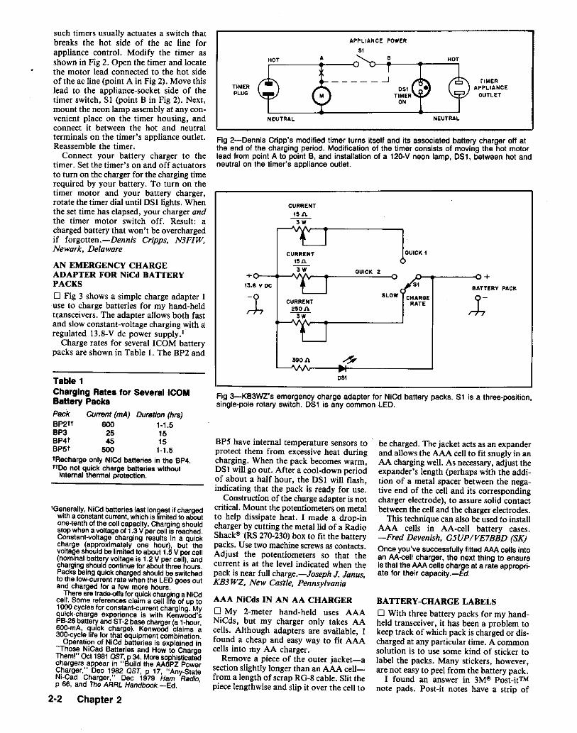
390"
Fig 2-Dennis Cripp's modified timer turns itself and its associated battery charger off atthe end of the charging period. Modification of the timer consists of moving the hot motorlead from point A to point B, and installation of a 120-V neon lamp, 051, between hot andneutral on the timer's appliance outlet.
CURRENT
"A3W
CURREN'T QUICK 1.."3W QUICK 2+ +
'13.8 v DC stBATTERY PACK
~SLOW CHARGE :tCURRENT RATE
2~OJ\--.-w
rullERAPPLIANCE
OUTLET
APPLIANCE POWER
51
TIMERPLUG
AN EMERGENCY CHARGEADAPTER FOR NiCd BATTERYPACKS
o Fig 3 shows a simple charge adapter Iuse to charge batteries for my hand-heldtransceivers, The adapter allows both fastand slow constant-voltage charging with aregulated 13.g-V de power supply.'
Charge rates for several ICOM batterypacks are shown in Table I. The BP2 and
such timers usually actuates a switch thatbreaks the hot side of the ac line forappliance control. Modify the timer asshown in Fig 2. Open the timer and locatethe motor lead connected to the hot sideof the ac line (point A in Fig 2). Move thislead to the appliance-socket side of thetimer switch, SI (point B in Fig 2). Next,mount the neon lamp assembly at any convenient place on the timer housing, andconnect it between the hot and neutralterminals on the timer's appliance outlet.Reassemble the timer.
Connect your battery charger to thetimer. Set the timer's on and off actuatorsto turn on the charger for the charging timerequired by your battery. To turn on thetimer motor and your battery charger,rotate the timer dial until DSllights. Whenthe set time has elapsed, your charger andthe timer motor switch off. Result: acharged battery that won't be overchargedif fargotten.-Dennis Cripps, N3FIW,Newark, Delaware
DSl
Fig 3-K83WZ's emergency charge adapter for NiCd battery packs. 51 is a three-position,single-pore rotary switch. D51 Is any common LED.
Table 1Charging Rates for Several ICOMBattery PacksPack Currant (rnA) Duration (hrs)BP2tt 600 1-1.5BP3 25 15BP4t 45 15BP5t 500 1-1.5tRecharge only NiCd batteries in the BP4.true not quick charge batteries without
internal thermal protection.
lGenerally, NiCd batteries last lon~est if chargedwith a constantcurrent, which is limitedto aboutone-tenth of the cell capacity. Charging shouldstop when a voltageof 1.3 V percell is reached.Constant-voltage charging results in a quickcharge (approximately one hour), but thevoltaqe should be limited to about 1.5 V per cell(nominal battery voltage is 1.2 V per cell), andcharging should continue for about three hours.Packs being quick charged should be switchedto the low-current rate when the LED goes outand charged for a few more hours.
There are trade-offsfor quick charging a NiCe!celt. Some references claim a cell life of up to1000 cycles for constant-current charging. Myquick-charge experience is with Kenwood'sPB-26battery and ST-2base charger (a t-hour,6OD-mA, quick charge). Kenwood claims a300-cycle life for that equipment combination.
Operation of NICd batteries Is explained in"Those NiCad Batteries and How to ChargeThem!" Qct 1981 QST, p34. More sophisticatedchargers appear in "Build the AA6PZ PowerCharger," Dec 1982 OST, p 17, "Any-StateNl-Cad Charger," Dec 1979 Ham RadIo,p 66, and The ARRL Handbook.-Ed.
2-2 Chapter 2
BP5 have internal temperature sensors toprotect them from excessive heat duringcharging. When the pack becomes warm,DSI will go out. After a cool-down periodof about a half hour, the DSI will flash,indicating that the pack is ready for use.
Construction of the charge adapter is notcritical. Mount the potentiometers on metalto help dissipate heat. I made a drop-incharger by cutting the metal lid of a RadioShack" (RS 270-230)box to fit the batterypacks. Use two machine screwsas contacts.Adjust the potentiometers so that thecurrent is at the level indicated when thepack is near full charge.-Joseph J. Janus,KB3 WZ, New Castle, Pennsylvania
AAA NiCds IN AN AA CHARGERo My 2-meter hand-held uses AAANiCds, but my charger only takes AAcells. Although adapters are available, Ifound a cheap and easy way to fit AAAcells into my AA charger.
Remove a piece of the outer jacket-asection slightly longer than an AAA cellfrom a length of scrap RG-g cable. Slit thepiece lengthwise and slip it over the cell to
be charged. The jacket acts as an expanderand allows the AAA cell to fit snugly in anAA charging well. As necessary, adjust theexpander's length (perhaps with the addition of a metal spacer between the negative end of the cell and its correspondingcharger electrode), to assure solid contactbetween the celland the charger electrodes.
This technique can also be used to installAAA cells in AA-cell battery cases.-Fred Devenish, G5UP/VE7BBD (8K)Once you've successfully fitted AAA cells intoan AA-cell charger, the next thing to ensureis that the AAA cells charge at a rate appropriate for their capacity.-Ed.
BATTERY-CHARGE LABELSo With three battery packs for my handheld transceiver, it has been a problem tokeep track of which pack is charged or discharged at any particular time. A commonsolution is to use some kind of sticker tolabel the packs. Many stickers, however,are not easy to peel from the battery pack.
I found an answer in 3M@ Post-itTMnote pads. Post-it notes have a strip of

weak wax-like adhesive along one edge.They are meant to be repeatedly placed andpeeled away without damage. [cut severalpieces small enough to fit inside the top ofthe battery pack. When a pack is discharged, I place the sticky strip so that thepaper covers the battery terminals. Aftercharging, [ move the strip so that theterminals are exposed. The strips can beused repeatedly, and there is no damage tothe battery packs.-Bob Schetgen, KU7G,ARRL HQ
REPLACEMENT BATTERY·PROTECTION PLATE INDICATESSTATE OF CHARGE
o [f you're tired of looking for the slidein plastic plate for your extra hand-heldbatteries, try the replacement shown inFig 4. Made from a 2-inch Pendallex foldertab, it protects the battery terminals againstshort circuits and allows you to slide in alabel indicating the battery's state ofcharge. My label says HOT on one side andRECHARGE on the other.-Greg Lane,K7SDW, 3970 Coronado Cir, NewburyPk, CA 91320.
r--- 2" ----j
d!_~o;_~Trim to Fit
Hand-Held-BatterySlide
Fig 4-Greg Lane replaced his battery·protection plate with a hanging-folder tabmodified as shown here. The slide-in labelIndicates state of charge.
ONE PROTECTIVE CASE FOR MANYBATTERY PACKS
o Dissatisfied with the performance of therechargeable battery pack provided with anewly purchased hand-held, many peoplepurchase optional battery packs withenergy capacities more suited to their needs.This often means that the overall height ofthe hand-held and new battery pack differsfrom that of the stock configuration-aproblem if you want to keep the radio ina protective case. To avoid the expense ofpurchasing a protective case for each transceiver/battery pack combination, I suggestthe following solution:
Purchase the protective case designed toaccommodate the hand-held and its largestoptional battery pack. When you usebattery packs smaller than maximum size,insert soft plastic-foam blocks cut to fit theextra case space. To avoid short-circuitingcharging contacts on the pack, be sure to
use nonconductive foam. Size the blocksto permit normal access to the hand-held'scontrols.-Marc Norikane, N7MBE, 190054th Ave SW, Seattle, WA 98/66
CONDUCTIVE PLASTIC CANDISCHARGE BATTERIES
o Recently, I purchased a pair of lithiumcells for backing up CMOS memory. TwoY2-inch-long radial leads protruded fromeach cell. To prevent the cell leads fromshorting together against metallic objectsin my junk box, I placed the cells, leadsfirst, into the black conductive foam I useto protect static-sensitive integratedcircuits.
My haste to protect the cells resulted intheir demise! Later, before installing oneof the cells in my circuit, I checked itsterminal voltage: 0 volts! I thought for amoment-and then I realized that antistaticfoam isn't also called "conductive foam"for nothing. An ohmmeter check revealedthat the resistance of the foam over a distance equivalent to the cell's lead spacingwas about 500 ohms. In effect, I hadplugged the lithium cells into a batterydischarger.-Otto Cepella, VE3HCD,Ottawa, Ontarioo The memory backup cell I ordered bymail arrived before I had time to install itin my VHF transceiver, so I put the cellpacking material and all-aside for severalweeks. The shipper had placed plastic foamover the cell terminals to protect themduring shipment. You guessed it: The foamwas conductive, and my "new" battery wasdead before I could install it!-Bruce E.Lackey, WB3HAE, Rockville, MarylandEditor's Note: It doesn't pay to put a powered-upPC board down on a piece of conductive foam,either: A friend of ours had to replace a 40-pinmicroprocessor chip after such a maneuver. Andconductive foam may not be the only plastic thatposes a short-circuit hazard: Conductive plasticbubble packing material may do in an energy cellor short a live circuit, too.
REPLACING BATTERY·CIRCUITFUSIBLE LINKS
o The battery circuit of many hand-heldtransceivers includes a protective fusechoke that prevents catastrophic damage inthe event of a battery short circuit. Unlikea panel-mounted fuse, however, a batteryfuse choke is not intended for easy replacement by its user. My first experience inhaving a burned-out fuse choke repaired byan authorized repair facility cost me$27-$7 for the fuse choke, and $20 forlabor. I decided to repair the choke myselfthe next time!
Investigation of my next burned-out fusechoke revealed a component consisting of14 turns of no. 33 magnet wire wound ona glass form about the size of a ';4 -wattresistor. A table in my Physics Handbookindicated that no. 33 wire melts at 5 A_the rating of the fuse choke.
I made my own choke by winding 14turns of Formvar-insulated no. 32 magnet
wire on a l-kn, ';4-W resistor. (No. 32 wasthe closest to no. 33 I had on hand. Thefusing current of no. 32 is 7 A-closeenough to no. 33's 5-A rating for mypurposes.) I insulated the replacementchoke with heat-shrink tubing before installing it in my transceiver.
Some fuse chokes include a ferrite beadon one lead. If this is so with your fusechoke, be sure to remove the bead from theburned-out choke and install it on yourhome-made replacement.-George H.Klaus, W2CJN, /40 Mill Dam Rd, Box T,Centerport, NY 1I72/-06/9
A 12-V DC POWER SYSTEM FORFIXED·STATION USE
o The 12-V power system that we now usein our shack was created like many otherprojects-the need finally overwhelmed thelaziness. My father (Ed Kabak, KA3DRD)and I share the same shack. After manyyears, we had accumulated many rigs, butnever enough power supplies to operatethem. The most direct solution would havebeen to buy more supplies, but this hascertain disadvantages: Power supplies arecostly in quantity, especially suppliescapable of operating high-power transceivers, and are unusable during mainpower failures.
We assembled our present power system(Fig 5) after carefully considering ouroptions. It was somewhat costly and timeconsuming to build, but its payoff issmoother operation of our ham shack. Weno longer waste time trying to "find thepower" for each of our 12-V-dc-poweredrigs. Each rig now has a permanent position and a permanent power feed. We alsohave uninterrupted power when commercial power is lost, with no switchingcircuitry. The system is intended to be usedin a reasonably permanent installation; wehave lived in the same location for manyyears.
Most of the Fig 5 components are housedin the bottom of a 5-ft-high, 19-inch-widerack. For energy storage and power-supplytime averaging, we use an automobilebattery (BTl) retired from service in mycar. It's connected as if it's a power supply:It has an isolation switch (SI, BATTERYOFF) and is externally fused. BTl is locatedexternal to the rack because of spacelimitations and the possibilities of acid spillsand gas buildup if the battery is charging.(Automotive lead-acid cells must behandled with care because of their acidicelectrolyte and their ability to sourcedangerously high currents when shorted.)The advantage in using an old battery is itslow cost (its trade-in value when you haveto buy a new battery). its relative simplicity,and its large energy-storage capacity. Wecan operate our station for several hourswithout commercial power; how long depends on exactly how much transmitting wedo. Higher battery capacity translates intomore operating time, of course.
Batteries and Generators 2-3

A plastic utility box (represented by theshaded line in Fig 6) serves as a distribution panel local to the individual rigs. Eachdistribution circuit is limited to 10 A, maximum, and the circuit fuses (F5-F8), Fig 5)are located in the rack, with a pilot lamp(DS3-DS6, Fig 5) on each to indicate thatoutput circuit power is available. (We usedpilot lamps, but if power consumption isa factor, LEDs can serve as indicators.)Each rig's power plug includes an in-linefuse (FlQ-F13, Fig 6) of the appropriate rating in its positive lead. These in-line fusesallow each rig to be moved elsewhere (suchas into mobile use) accompanied by its fuse.For this purpose, we selected a fused connector assembly (Radio Shack? no.270-02.5) that is simple, sturdy, and polarized. All of our 12-V rigs now use thissame connector.
The power supplies (Power Supplies Iand 2, Fig 6) are connected so that they can
be enabled or disabled at any time withlittle impact on the system. Each supplymust have internal protection-fuses, circuit breakers, crowbars or other protectivecircuitry-and is connected to the bus viaa switch (S2 and S3, Fig 6), an isolationdiode (Dl-D4, Fig 5), and a fuse (FI-F4,Fig 5) in the rack. The rack fuses provideadditional protection, and the combinationof the diodes and supply-output switchesallow the power supplies to be connectedto or disconnected from the power bus atany time. The diodes are necessary; theyprevent current flow back into a turned-offsupply-especially important when thepower fails. Pilot lamps (DSI and DS2, Fig5) indicates that power is being fed to thebus. We match the power-supply outputvoltages (the output voltage of one supplyis adjustable). The isolation diodes allowa variety of different power sources to feedthe bus at the same time-all of those crea-
tive Field Day ideas can now follow youhome!
We use Power Supply 2 to keep BTlcharged, or when we have only small loadsoperating. Supply 2 is capable of sourcingI.75 A and is frequently left on line, hutis occasionally turned off when the systemis unloaded and the battery is fully charged.Our present Power Supply I is a muchlarger, regulated, surplus, computer powersupply, and is only brought on-line duringtransmitter operation. We shut it downwhen we're not using our rigs, or when therigs are on but we don't intend to transmit.With both supplies on line-that is, operating in parallel-much more current is available than our transceivers require inreceive, and the battery does not supplycurrent; if necessary, it can charge duringthese periods. As the load on the systemincreases beyond the capacity of the supplies, the battery provides the balance. This
F5
A +F6 to Loads
B(Fig 6)
F7spare
F8spare
220 !l1,72W
220 n172W
220 0172W
220 !l"i"72W
Heavy lines indicate no. 12stranded, insulated wire.
T82 T8301 F1 --- L1+ from
Power Supplies02 F2 ---
(Fig 6) L22 2 2
03 F3 --- L3spare 3 3
04 F4 =L4spare 4 4
5 5
220 0 DS3V2W DS1 OUTPUT 1
SUPPLY 1ON
DS4OUTPUT 2
SUPPLY 2
220 n ON
172W DS5
J1 OUTPUT 3
TESTJ2 OS,
S1OUTPUT 4
BATTERYOFF +
M1V 0-15
2
..., from 1Power Supplies
(Fig 6)
spare
spare
T81
2
3
4
T84
A- to Loads
8(FIg 6)
2
3 spare
4 spore
273-104).Ml-D-15 V de voltmeter (RS no.
270-1754).Sl-SPST toggle switch, rated at 20 A or
more at 12 V (or more) dc.TB1-TB4--Heavy-duty barrlar strip with no.
B screws.F1·F8 are held in four-position fuse blocks
(RS no. 270-742).
272-331).F1-F8-Dc fuse rated to provide protection
at the bus load current..Jt. J2-Nylon binding post (RS no.
274-662).L1-L4-Approximately 100 mH, 10 A: As
many turns of no. 12, insulated, strandedwire as can be wound on a snaptogether, toroidal choke core (RS no.
Fig 5-Schematie of the 12-V de power system. Except for the components shown in the screened box, this circuitry is housed in anequipment rack. See text and Fig 6,BT1-Used, 12-V lead·acid automotive
battery.Ot, C2-o.1-~F. 5O-V, disc-ceramic
capacitor (Radio Shack" no. 272-135).D1-D4-Power-rectifier diode capable of
safely handling load current, 15 Aminimum.
DSf-DS6-12-V, high-brightness,incandescent-lamp assembly (RS no.
2-4 Chapter 2
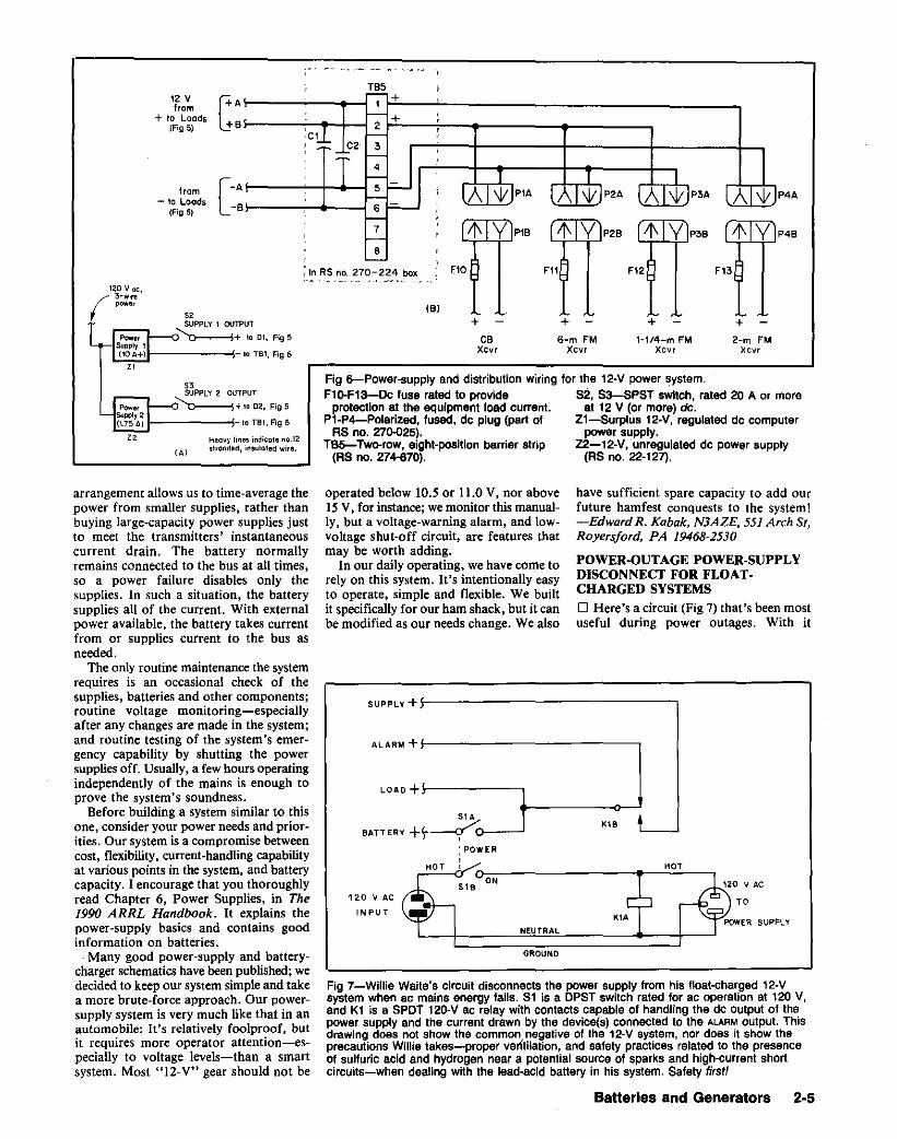
TB'12 Vfrom
+ fa Loads(Fig 5)
from- to Loads
(Fig 5)
r+ A
hB
[
- A
-B
~ +1f-- +
,2 ,
cel ~,,-~f --=-,
4 !
- , T T 1
-=- i=- lA I\lI JP1A IAI\lIjp2A IAI\j,tlp3A lAl\lIJ~=--
, 7 , rIj\ IVIP1B rIj\ IVlp2B (Ij\ IVlp'B rIj\ IVlI-~
P4A
P4B
L~n RS no. 270-224 box no F11 F12 FB
52SUPPLY 1 OUTPUT
~+ to 01, FigS
- 10 T81, Fig 5
+2-m FM
xcvr
+H/4-m FM
Xcvr
+6-m FM
Xcvr
+CB
Xcvr
IB)
Fig 6-Power-supply and distribution wiring for the 12-V power system.F1o-F13-Dc fu.e reted to provide 52, S3-SPST switch, rated 20 A or more
protection at the equipment load current. at 12 V (or more) de.P1·P4-Polarized. fused. de plug (part of Zl-Surplus 12·V, regulated de computer
RS no. 270-025). powar supply.T85-Two-row, eight-position barrier strip Z2-12-V, unregulated de power supply
(RS no. 274-670). (RS no. 22-127).
Heo~y lines indicole no.12stranded, insulated wire.IA}
saSUPPLY 2 OUTPUT
~+IQDZ.F;g5
!-------!-IO TB1,Fig 5
ALARM +f---------------,
SUPPLY + ..1-----------------...,
K1B LJ
have sufficient spare capacity to add ourfuture hamfest conquests to the system!-Edward R. Kobak, N3AZE, 551 Arch St,Royersford, PA 19468-2530
POWER·OUTAGE POWER-SUPPLYDISCONNECT FOR FLOAT·CHARGED SYSTEMS
o Here's a circuit (Fig 7) that's been mostuseful during power outages. With it
NEUTRAL
GROUND
LOAD +1-------,51 A
BATTERY +t~:>----': POWER,
HOT I
518 ON
120 V AC
INPUT
Fig 7-Willie Waite's circuit disconnects the power supply from his float-charged 12-Vsystem when ae mains energy fails. 81 is a DPST switch rated for ae operation at 120 V,and K1 is a SPOT 120-V ae relay with contacts capable of handling the de output of thepower supply and the current drawn by the device(s) connected to the ALARM output. Thisdrawing does not show the common negative of the 12-V system, nor does it show theprecautions Willie takes-proper ventilation, and safety practices related to the presenceof sulfuric acid and hydrogen near a potential source of sparks and high-current shortcircuits-when dealing with the lead-acid battery in his system. Safety first!
operated below 10.5 or fI.OV. nor above15 V, for instance; we monitor this manually, but a voltage-warning alarm, and lowvoltage shut-off circuit, are features thatmay be worth adding.
In our daily operating, we have come torely on this system. It's intentionally easyto operate, simple and flexible. We builtit specifically for our ham shack, but it canbe modified as our needs change. We also
arrangement allows us to time-average thepower from smaller supplies, rather thanbuying large-capacity power supplies justto meet the transmitters' instantaneouscurrent drain. The battery normallyremains connected to the bus at all times,so a power failure disables only thesupplies. In such a situation, the batterysupplies all of the current. With externalpower available, the battery takes currentfrom or supplies current to the bus asneeded.
The only routine maintenance the systemrequires is an occasional check of thesupplies, batteries and other components;routine voltage monitoring-especiallyafter any changes are made in the system;and routine testing of the system's emergency capability by shutting the powersupplies off. Usually, a few hours operatingindependently of the mains is enough toprove the system's soundness.
Before building a system similar to thisone, consider your power needs and priorities. Our system is a compromise betweencost, flexibility, current-handling capabilityat various points in the system, and batterycapacity. I encourage that you thoroughlyread Chapter 6, Power Supplies, in The1990 ARRL Handbook. It explains thepower-supply basics and contains goodinformation on batteries.
Many good power-supply and batterycharger schematics have been published; wedecided to keep our system simple and takea more brute-force approach. Our powersupply system is very much like that in anautomobile: It's relatively foolproof, butit requires more operator attention-especially to voltage levels-than a smartsystem. Most "12-V" gear should not be
Batteries and Generators 2·5
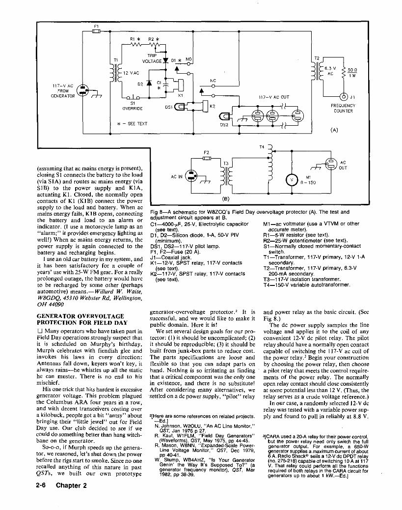
F1
Rl * R2 *
* - SEE TEXT
50 01W
J1
FREQUENCYCOUNTER
(A)
6.3 VAC
D1 * NOTRIP
VOLTAGET1
117-Y ACFROM
GENERATOR
T4
(8)
ACOUT
M10-150
and power relay as the basic circuit. (SeeFig 8.)
The de power supply samples the linevoltage and applies it to the coil of anyconvenient 12·V dc pilot relay. The pilotrelay should have a normally open contactcapable of switching the 117-V ac coil ofthe power relay. 3 Begin your constructionby choosing the power relay, then choosea pilot relay that meets the control requirements of the power relay. The normallyopen relay contact should close consistentlyat some potential less than 12 V. (Thus, therelay serves as a crude voltage reference.)
In our case, a randomly selected 12-V derelay was tested with a variable power supply and found to pull in reliably at 8.8 V.
Ml-ac voltmeter (use a VTVM or otheraccurate meter).
Rl-5-W resistor (see text),R2-25·W potentiometer (see text).51-Normally closed momentary-contact
switch.Tl-Transformer, l17-V primary, l2-V 1-A
secondary.T2-Transformer, l17-V primary, 6.3-V
200-mA secondary.T3-1l7-V isolation transformer.T4-150-V variable autotransformer.
31CARA used a 20-A relay for their powercontrol,but the power relay need only switch the fullgenerator output. For example, a 650-Wgeneratorsuppliesa maximumcurrent of about6 A. Radio Shacks' sells a 12-Vde DPOTrelay(no. 275-218)capable of switching 10A at 117V. That relay could perform all the functionsrequired of both relays in the CARA circuit forgenerators up to about 1 kW.-Ed.]
F2
Fig a-A schematic for W8ZCQ's Field Day overvoltage protector (A). The test andadjustment circuit appears at B.C1-4000-~F, 25-V, Electrolytic capacitor
(see text).01, 02-Silicon diode, l-A, 50-V PIV
(minimum),DS1, DS2-117-V pilot lamp.F1, F2-Fuse (20 A). .Jl-Coaxial jack.Kl-12-V, SPST relay, l17-V contacts
(see text).K2-1l7-V, 5PST relay, l17-V contacts
(see text).
2[Hereare some references on related projects.-Ed.]N. Johnson, W20LU, "An AC Line Monitor,"
QST, Jan 1976 p·27.R. Kaul, Wl FLM, "Field Day Generators"
(Waveforms), QST, May 1975, pp 44-45.R. Mason, WBNN, "Expanded-Scale Power
Line Voltage Monitor," OST, Dec 1979,pp 40-41.
W. Stump, WB4AHZ, "Is Your GeneratorGenin' the Way It's Supposed To?" (agenerator frequency monitor), QST, Mar1982. pp 38-39.
generator-overvoltage protector. 2 It issuccessful, and we would like to make itpublic domain. Here it is!
We set several design goals for our protector: (1) it should be uncomplicated; (2)it should be reproducible; (3) it should bebuilt from junk-box parts to reduce cost.The parts specifications are loose andflexible so that you can adapt parts onhand. Nothing is so irritating as findingthat a critical component was the only onein existence, and there is no substitute!After considering many alternatives, wesettled on a de power supply, "pilot" relay
(assuming that ac mains energy is present),closing SI connects the battery to the load(via SIA) and routes ac mains energy (viaSIB) to the power supply and KIA,actuating K 1. Closed, the normally opencontacts of Kl (KIB) connect the powersupply to the load and battery. When acmains energy fails, KIB opens, connectingthe battery and load to an alarm orindicator. (I use a motorcycle lamp as an"alarm;" it provides emergency lighting aswell!) When ac mains energy returns, thepower supply is again connected to thebattery and recharging begins.
I usean old car battery in my system, andit has been satisfactory for a couple ofyears' use with 25-W FM gear. For a reallyprolonged outage, the battery would haveto be recharged by some other (perhapsautomotive) means.-Willard W. Waite,W8GDQ, 45310 Webster Rd, Wellington,OH 44090
GENERATOR OVERVOLTAGEPROTECTION FOR FIELD DAY
o Many operators who have taken part inField Day operations strongly suspect thatit is scheduled on Murphy's birthday.Murph celebrates with fiendish glee andinvokes his laws in every direction:Antennas fall down, keyers won't key, italways rains-he whistles up all the statiche can muster. There is no end to hismischief.
His one trick that hits hardest is excessivegenerator voltage. This problem plaguedthe Columbus ARA four years in a row,and with decent transceivers costing overa kilobuck, people got a bit "antsy" aboutbringing their "little jewel" out for FieldDay use. Our club decided to see if wecould do something better than hang witchbane on the generator.
So-a-a, if Murph speeds up the generator, we reasoned,let's shut down the powerbefore the rigs start to smoke. Since no onerecalled anything of this nature in pastQSTs, we built our own prototype
2·6 Chapter 2

Fig 9-A photo of WeZCQ's completesystem.
Hence, we built an adjustable de powersupply that provides from 8.1to 10.7 V atthe pilot-relay coil when the input linevoltage is 117 V.
The most suitable potentiometer in ourjunk box was 25 ohms, rated at 25 W. Itrequires a series combination with a 12-0resistor to produce the desired voltagerange for the pilot relay. The potentiometerand Rl values must be determined experimentally for each relay.
Our unit was built in a Bud 8 x 8 Y4 XlOYl-inch cabinet, but there are no firmconstruction rules. A three-inchshelf insidethe box holds the relays. The rectifier diode
is rated at I A and 1000 PIV. The filtercapacitor is 4000 ~F at 25 WVDC, but anycapacitance greater than 500 jlF should do.
An ac voltmeter is the final indispensablecomponent; the pilot lights and components related to the frequency counter areoptional. Such options were incorporatedbecause the parts were available and thefeatures useful: Since a Heathkit frequencycounter was available, an outlet wasprovided for it.
Test and adjust the circuit by drivingit through a variable-voltage transformer.Change RI and the potentiometer, if necessary, to allow adjustment of the trip potential from about 117 to 130 V ac. In the caseof our prototype, the range-was from 100to 135 V. Once you have established thecomponent values, mark the front panel.
At the outset, we only intended toprotect one rig. After some of our club"authorities" examined and blessed thenew circuit, we decided to protect allCARA Field Day equipment. Out came thehole punch, and another outlet was addedfor an extension that would serve the restof the camp.
Field Day soon arrived and passed. Thegenerator output varied from 122to 128 Vand 58 to 62 Hz during the contest(frequency changed in direct relation to theoutput voltage), and the protector shut
down the power twice. Each time, the voltage had reached the 130-V setting, butMurphy had been defeated-no rigs weredamaged.-Dan Umberger, W8ZCQ,Columbus, Ohio
REDUCING THE CHANCE OFGENERATOR FIRE ON FIELD DAY
o Don't refuel a running generatorwithout taking special precautions.Gasoline's ignition temperature is lowenough for a fuel spill on a running engineto result in disaster for the engine and theperson filling the fuel tank!
Falmouth Amateur Radio Associationmember Jim Leavitt, KCIKM, suggests thismeans of keeping gasoline-drivengenerators fire-free on Field Day: Removethe generator fuel tank from the engine andmount it on a stanchion at a distance fromthe generator. Run a hose (rated to carrygasoline) between the tank and generator.For added safety, equip the hosewith a driploop at the tank, mark the hose with ribbons at intervals, and ensure that no Onecan trip over or walk into the hose. Haveanother club member stand ready with afire extinguisher when the tank isrefueled-and don't refuel the generatoralone, or when you're tired or sleepy.James J. Priestly, KAIL/K, ARRL PIA,55 Neshobe Rd, New Seabury, MA 02649
Batteries and Generators 2-7

I
I
I
I
I
I
I
I
I
I
I
I
I
I
I
I
I
I
I
I
I
I
I
I
I
I
I

CHAPTER 3=============
Mobile Stations
MILK-CRATE MOBILE
o Half the fun of ham radio is the abilityto operate from somewhere other thanhome. Today's 12-volt transceivers offerunprecedented opportunities to work theworld from out in the world. But why waitto get to another operating site when youcan operate on the way? Getting a mobilestation running at VHFIUHF and MF/HFis easy. and need not involve attacking yourcar with a drill. Magnetic- or bumpermount antenna systems work well withoutcar modification, and a good antenna tuner(manual or automatic) can help offset amobile MF/HF antenna's narrow SWRbandwidth. The only problem left to solveis keeping all the equipment from bouncingaround in the car!
My solution? RF in a box! See Fig 1. Jim(WD8JCI) Orihood and I mounted all myequipment in a plastic milk crate.' (He didmost of the work; I assisted.) We laid thecrate on its side and cut an l l-inch squareout of its bottom. The cut-out crate bottom, with its l-inch rim, becomes the box'sback. The cutout allows access to the gear'srear-panel connectors. The crate's open top
'Availablein various colorsat home-improvement,kitchen and variety stores.
Fig 1-Charlie Cotterman and his milkcrate mobile, in place and operational. Themilk crate holds MF/HF and 2-metertransceivers, straight key, and speakers ina compact package that's as useful-andfun-at home as it is on the road. Charlie's"Salt, Sentiment and Solid-State" (OST,July 1990, pages 52·53) described just oneof the adventures he's had with this setup.
serves as the box front. A piece of \i4 -inchplywood, fastened with screws to the boxbottom, serves as a base for the bottommost rig (a Yaesu FT-757GX in my setup).
(this photo and Fig 1 by David Head, KBDH)
Small-diameter bungee cords, hookedthrough screw eyes driven into the board,hold the '757 in place.
Another piece of \i4 -inch plywood, heldin place with wood screws and two va-inchsquare wood-molding rails, serves as a shelftwo-thirds of the way above the box bottom. This shelf supports my 2-meter transceiver (a Kenwood TR-7850, underslung inits mounting bracket) and an MF IHFantenna tuner (an MFJ-949D, force-fit intoplace between the shelf and box top, asallowed by the box's flexible plastic).Placing the tuner flush with the box's rightside leaves just enough space to bolt a smallstraight key (yes, I operate mobile CW) tothe shelf between the tuner and the left boxwall. (You can't see the key in Fig I becauseI also use this space to hold notepads.) The'7850's boltom clears the '757's top byabout V2 inch. I positioned the '7850 toallow access to the '757's top-mountedkeyer controls.
This compact installation blocks bothradios' internal speakers. Two car-stereospeakers, one for each rig, installed on a
Mobile Stations 3-1

+13.8 V
Ground
01LMJ95
.,47 kO
1/4 W
A CIGAR-LIGHTER POLARITYTESTERo Before you plug your equipment intothe cigar lighter of your new (or anunknown) car, it's a good idea to test thelighter polarity. Fig 3 shows a simple meansof doing this. The circuit tests for a centerpositive condition at the lighter; if thelighter is powered, and + 12 volts isconnected to its center contact, DSllights.Carry this gadget with your "pluggable"12-V gear; it could save your transceiverfrom a quick demise!-Lin Cook, WIJRS,788HighlandAve, SPort/and, ME 04106
MOBILE COOLING FAN SENSES RFo Some compact, high-power VHF transceiversget very hot when transmitting andcan benefit from forced-air cooling. Thesimple circuit shown in Fig 4 helps suchradios cool themselves. It sensesRF leakagefrom coaxial cable and turns on a coolingfan whenever the radio is transmitting.
I tested this circuit with Belden RG-58Cand Tandy RG-8M (foarn-dielectric miniature RG-8) cables. The Tandy productexhibits about twice the leakage as theBelden; about 5 watts into such coax at2 meters turns the fan on reliably.
Inductor Ll consists of 10 turns of insulated hookup wire-H2O to 24-wrappedtightly around the coax and taped intoplace. You need not alter the coax in anyway. (Although my test circuit worked wellwith 10turns, your version may work better with more or less turns. You canoptimize Ll by connecting a voltmeteracross Rl and adjusting Ll for a peak reading while transmitting.)
Dl rectifies the signal. Cl filters theresulting de, which is applied to Ql's baseto turn QI on. RI keeps QI turned offduring no-drive periods by pulling Ql'sbase to ground.
Ql, a National Semiconductor ultrareliable power transistor, has built-in thermaloverload protection and current and powerlimiting, making it almost impossible todestroy. The LM395 is available from DigiKey, 701 Brooks Ave S, Box 677, ThiefRiver Falls, MN 56701-0677 (telephone800-344-4539, fax 218-681-3380).
Bl can be any small de fan, such asRadio Shack's 273-243 or 273·244. I've
C,0.1 ~F
Ceramic
1N914or 1N4148
01
LEO
L1-""""""""'''1--1 Coax to AntennaVHfTransceiver
2.2 en,1/4 W
Radio Shack274-331Lighter Plug
problem for vehicles I've purchased inrecent years: a simple way to mount a smalltransceiver over the car's transmissionhump-without drilling holes in the dashboard or front-seat floor.
Use a fairly thick piece of sheet metal toform a U-shapedbase capable of straddlingthe hump. Bolt the rig's mounting bracketto the base's top surface. Proportiondimension C to be slightly narrower thanthe hump width at floor level.This permitsyou to spring out the mount's sides wheninstalling it over the hump.
The first time I used this mount, I didnot think to install the six sheet-metalscrews shown in Fig 2. Consequently, thetransceiver-and-mount combination tiltedforward when 1 braked! The sheet-metalscrews bite into the car's floor mat orcarpeting, keeping the entire package solidly in place.
You may want to make dimension Bshorter than dimension A. This allows thetransceiver's front panel to tilt upward,making its controls and display easier tosee.
I use this transceiver-mountingtechniquein my 1989 Grand Marquis, and found itto be entirely satisfactory in a PontiacBonneville and a 1986Buick Century Ltd.Mounting your rig this way offers anotheradvantage: You can easily remove transceiver and mount from the car to preventtheft while keeping your gear in goodshape. (Normally, constant removal andreinstallation of a mobile transceiver andits mounting bracket leads over time toscratches and mars on the rig's case. Thesystem shown in Fig 2 avoids this.)-DougDeMaw, WIFB, Luther, Michigan
Fig 3-Lin Cook's clgar·lighter polaritytester uses just three parts.
Fig 4-Jay Hamlin's circuit senses coax RF leakage-and perhaps outside-of-shieldcurrents-i-to drive a transistor that turns on a cooling fan. The text tells more about theparts and what they do.
16. J/8'Sheet-lolelol
Scre"(6 Placu)
114ar16Sleel ar "'Iuminum
~--- c ----oj
BrQc.et IolQunllnQ Holes(.... Necesoary)
A->::» "E> E>
HUMP MOUNT FOR MOBILE RIGSo Most of us have a hard time decidingwhere and how to mount a mobile transceiver in a new vehicle. It seems that carmanufacturers generally overlook radiooperators when laying out cockpits anddashboards! Fig 2 shows how I solved this
2Sold in auto-partsstores, in bubblepacks, usuallyon the accessories rack. The cables are madeby Motormite Manufacturing.
piece of plywood cut to clear the crate'shandle holes and secured to the crate lapwith wood screws, take their place andprovide good mobile audio.
Power for the station box comes directlyfrom the car battery via #12 wire, with aholder-mounted 3D-ampere fuse installed inseries with each lead as close to the batteryterminals as possible. Two terminal stripson a small piece of plywood (kept underthe dashboard on the package tray in frontof the passenger seat) provide accessto thisbus. All of the box's 12-voltfeeds come offthis board via connectors made fromGeneral Motors alternator-cable extenders.! These are insulated, lockingpolarized plugs with color-coded #14 leads.1 cut the stock assembly in half and lockits plugs together.
The station box sits in the passenger seatand can be secured with the seat/shoulderbelt. The angled speaker enclosures directsound toward me, and operating the equipment controls doesn't distract me fromdriving. (With safety in mind, however, Ipreset as many equipment functions as possible before starting a trip.)
When I come home, all the radios stayin the crate-the whole thing sits on theshack table as is! My station power supply'sconnectors duplicate those used betweenthe station box and the car electricalsystem, so nothing needs to be removedor rearranged.-Charlie Cotterman.KA80QF, Dayton, Ohio
Fig 2-Ooug DeMaw'shump mount keapsa mobile rig In place with the help of sheetmetal screws that prevent the mount andrig from sliding during speed changes andturns. No dimensions are shown becauseyou'll nead to tailor the assembly to thesize of your car's floor hump.
3-2 Chapler 3
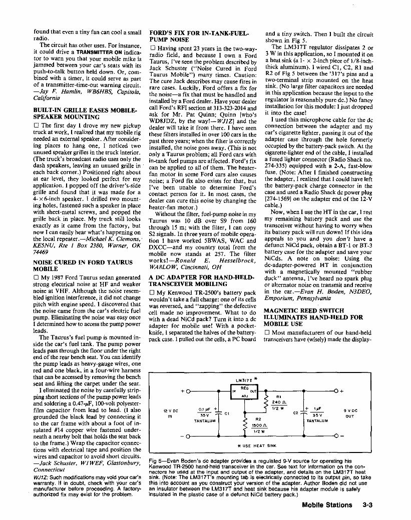
* USE HEAT SINK
Fig 5-Evan Boden's de adapter provides a regulated 9-V source for operating hisKenwood TR-2500 hand-held transceiver in the car. See text for information on the connectors he used at the input and output of the adapter, and details on the LM317T heatsink. (Note: The LM317T's mounting tab is electrically connected to its output pin, so takethis into account as you construct your version of the adapter. Author Boden did not usean insulator between the LM317T and heat sink because his adapter module is safelyinsulated in the plastic case of a defunct NiCd battery pack.)
LM317T *
MAGNETIC REED SWITCHILLUMINATES HAND·HELD FORMOBILE USE
o Most manufacturers of our hand-heldtransceivers have (wisely) made the display-
9 V DC
OUT
+
and a tiny switch. Then I built the circuitshown in Fig 5.
The LM317T regulator dissipates 2 or3 W in this application, so I mounted it ona heat sink (a 1- X 2-inchpieceof 1/8·inchthick aluminum). I wired CI, C2. Rl andR2 of Fig 5 between the '317's pins and atwo-terminal strip mounted on the heatsink. (No large filter capacitors are neededin this application because the input to theregulator is reasonably pure dc.) No fancyinstallation for this module: I just droppedit into the case!
I used thin microphone cable for the deconnection between the adapter and mycar's cigarette lighter, passing it out of theadapter case through the hole formerlyoccupied by the battery-pack switch. At thecigarette-lighterend of the cable, I installeda fused lighter connector (Radio Shack no.274-335) equipped with a 2-A, fast-blowfuse. (Note: After I finished constructingthe adapter, I realized that I could have leftthe battery-pack charge connector in thecase and used a Radio Shack de power plug[274-15691 on the adapter end of the 12-Vcable.)
Now, when I use the HT in the car, [ restmy remaining battery pack and use thetransceiver without having to worry whenits battery pack will run down! If this ideaappeals to you and you don't have adefunct NiCd pack, obtain a BT-t or BT-3battery case for the adapter and save yourNiCds. A note on noise: Using thede-adapter-powered HT in conjunctionwith a magnetically mounted "rubberduck" antenna, I've heard no spark plugor alternator noise on transmit and receivein the car.-Evan H. Boden, N3DEO,Emporium, Pennsylvania
I REG II" our
AOJ -. • RI
: 240 n,
0.1 JlF + 1/2 WC, -~~~:: C\ >ov
TANTALUM . R' TANTALUM> 1500n.1I2W
12 V DC
IN
+
FORD'S FIX FOR IN·TANK.FUEL.PUMP NOISE
o Having spent 23 years in the two-wayradio field, and because I own a FordTaurus, I've seen the problem described byJack Schuster ("Noise Cured in FordTaurus Mobile") many times. Caution:The cure Jack describes may cause fires inrare cases. Luckily, Ford offers a fix forthe noise-a fix that must be handled andinstalled by a Ford dealer. Have your dealercall Ford's RFI section at 313-323-2014 andask for Mr. Pat Quinn; Quinn [Who'sWD8JDZ, by the way!-WJJZI and thedealer will take it from there. I have seenthese filters installed in over 100cars in thepast three years; when the filter is correctlyinstalled, the noise goes away. (This is notonly a Taurus problem; all Ford cars within-tank fuel pumps are affected. Ford's fixcan be applied to all of them. The heaterfan motor in some Ford cars also causesnoise; a Ford fix also exists for that. butI've been unable to determine Ford'scontact person for it. In most cases, thedealer can cure this noise by changing theheater-fan motor.)
Without the filter, fuel-pump noise in myTaurus was 10 dB over S9 from 160through 15 m; with the filter, I can copyS2 signals. In three years of mobile operation I have worked 5BWAS, WAC andDXCC-and my country total from themobile now stands at 257. The filterworks!-Ronald E. Hesselbrock,WA8LOW, Cincinnati, OH
A DC ADAPTER FOR HAND-HELD·TRANSCEIVER MOBILINGo My Kenwood TR-2500's battery packwouldn't take a full charge: one of its cellswas reversed, and "zapping" the defectivecell made no improvement. What to dowith a dead NiCd pack? Turn it into a deadapter for mobile use! With a pocketknife, I separated the halves of the batterypack case. 1pulled out the cells, a PC board
found that even a tiny fan can cool a smallradio.
The circuit has other uses. For instance,it could drive a TRANSMITTER ON indicator to warn you that your mobile mike isjammed between your car's seats with itspush-to-talk button held down. Or, combined with a timer, it could serve as partof a transmitter-time-out warning circuit.-Jay F. Hamlin, WB6HBS, Capitola,California
BUILT·IN GRILLE EASES MOBILE·SPEAKER MOUNTINGo The first day I drove my new pickuptruck at work. I realized that my mobile rigneeded an external speaker. After considering places to hang one, I noticed twounused speaker grilles in the truck interior.(The truck's broadcast radio uses only thedash speakers, leaving an unused grille in .each back corner.) Positioned right aboutat ear level, they looked perfect for myapplication. I popped off the driver's-sidegrille and found that it was made for a4-x6-inch speaker. I drilled two mounting holes. fastened such a speaker in placewith sheet-metal screws, and popped thegrille back in place. My truck still looksexactly as it came from the factory, butnow I can easily hear what's happening onthe local repeater .-Michael K. Clemons,'KE5NU, Rte I Box 2380, Warner, OK74469
NOISE CURED IN FORD TAURUSMOBILEo My 1987 Ford Taurus sedan generatedstrong electrical noise at HF and weakernoise at VHF. Although the noise resembled ignition interference. it did not changepitch with engine speed. I discovered thatthe noise came from the car's electric fuelpump. Eliminating the noise was easy onceI determined how to accessthe pump powerleads.
The Taurus's fuel pump is mounted inside the car's fuel tank. The pump powerleads pass through the floor under the rightend of the rear bench seat. You can identifythe pump leads as heavy-gauge wires, onered and one black. in a four-wire harnessthat can be accessedby removing the benchseat and lifting the carpet under the seat.
I eliminated the noise by carefully stripping short sectionsof the pump power leadsand soldering a 0.47-pF, lOO-volt polyesterfilm capacitor from lead to lead. (I alsogrounded the black lead by connecting itto the car frame with about a foot of insulated #14 copper wire fastened underneath a nearby bolt that holds the seat backto the frame.) Wrap the capacitor connections with electrical tape and position thewires and capacitor to avoid short circuits.-Jack Schuster, WI WEF, Glastonbury,ConnecticutWJ1Z: Such modifications may void your car'swarranty. If in doubt, check with your car'smanufacturer before proceeding. A factoryauthorized fix may exist for the problem.
Mobile Stations 3-3

Fig 6-The ham antenna on Warren Gregory's station wagon looks lik~ just another mobilevertical until a closer look reveals a PVC-pipe support at rooftop level. ThISarrangement keepsthe antenna vertical regardless of driving speed, but still allows the antenna to be folded forgarage and car-port parking. That 45 0 fitting at the roof rack angles the support arm backward tomeet the Hustler just below its folding point. T fittings connect the arm to the roof rackand antenna. See the text and Fig 7.
light switches in these rigs momentary sothat we do not accidentally drain ourbatteries and find ourselves out in rabbitcountry without radio communication. Because my LCD-equipped Yaesu FT-411hand-held serves in base-station, portableand mobile roles, its momentary-displaylighting feature is not always necessary ordesirable. Continuous display lighting isparticularly valuable during mobile operation at night. I decided to fiddle with myFT-411's lighting circuitry to make itmomentary and switchable onloff. Studying the Ff-411 's servicemanual, I debatedinstallinga subminiature phone jack, wiredin parallel with the momentary displaylamp switch, along the side of the transceiver case, smothering the jack in siliconesealant and using a wired-shorted subminiature plug to turn my lighton. It wouldwork, but. ..
In a miniature blinding flash, a betteridea struck me. [ installed a tiny magneticreed switch, wired in parallel with thedisplay-lamp switch, inside the FT-411 'scase. Then [ taped a magnet to the rig'smobile mounting bracket to activate theswitch. Now, when I slip the radio into itsholder, its display light automaticallycomes on without any further action on mypart. And I didn't have to drill any holesin the Ff-411's case! The lamp generatesslight heat, but this has caused no problemsin my transceiver. The small magnet I useto activate the switch has no effect onprogramming or any other transceiverfunction. I intend to mount a magnet ona hinge at my base station so that I canselect continuous display illumination atwill, depending on the time of day.
Here are a few installation tips: Undertake this project only after acquiring andstudying your transceiver's service manual;installingthe reed switchmay require trickydisassemblyand reassembly. Pre-wire yourreed switch very carefully and coat it andits leads with heat-shrink tubing to guardagainst vibration and short circuits. Withcareful soldering and, a. bit of luck, you'lljust have sufficient room to install theswitch inside your hand-held.-TomTurner, VOl TV, 7Jervis PI, SI John's, NFAlA 3Zl
STABILIZING THE MOBILE WHIPo One of the problems faced by AmateurRadio operators who operate MF/HFmobile is keeping a car-mounted whipantenna vertical and stable while driving.In this contest with the wind, a verticalantenna may be more horizontal thanvertical much of the time!
Some hams just surrender and work onlyVHF/UHF mobile. More-persistentMFIHF mobileers remain on the lowbands, guying their antennas withmonofilament fishing line or smalldiameter cord. (I tried this with my rearfender-mounted Hustler mobile antenna.It worked, but my wife disapproved of the
3-4 Chapter 3
Fig 7-At A, a close-up of the roof-rackend of Warren Gregory's mobile-antennasupport arm. B shows the tight fit betweenthe Hustler's slip lock and the antennamounted PVC T. This photo also shows thesmaller-diameter PVC pipe Warren slippedinside the T to obtain that tight slip-lock-to-T fit.
practice, and often the string sang as ]drove at highway speeds. When the frontguy broke on Interstate 70, I thought verystrongly of going to 2 meters!)
With the help of Werner Dolder,AA4IX, ] devised a solution to thisproblem. See Fig 6. A PVC-pipe arm,attached to my station wagon's roof rack,supports the Hustler at its fold-over point,holding the antenna vertical and immovable.
I began constructingthe support by care-
(B)
fully measuring the distance between theHustler's fold-over point and the roofrack-at a 450 angle relativeto the car bodyand to the antenna. After figuring wherethe arm would attach to the roof rack, Iprepared a PVC T to fit the roof rack byfiling a flat on one side of the T for a closerfit with the rack. To make this T moreresistant to the pressure of its mountingbolts, I force-fit a pieceof smaller-diameterPVC pipe through the T's cross bar andglued it into the T. After the glue hardened,

Fig 8-W5LAN's 2-meter mobile antenna.
WINDOWEDGE
TAPEELEMENT
ON WINDOW
///
coNNEcr"COAXSHIELDTO WJNOOW:OftOuND,LIN£' HERE
have a low-enough profile. I reinstalled mywindow-mount 2-meter antenna anddevised a 44O-MHzantenna-made of selfadhesive copper tape and mounted in therear window of the Camaro!
See Fig 9. Actually, only the vertical element consists of tape. The end of the coaxshield is connected to the car's windowedge ground line; this serves as a groundplane. Result: a simple 44O-MHz antennathat works quite well for local use. Itdoesn't even look like an antenna whenexamined closely: Most people think thecopper tape has something to do with a caralarm!-Carl G. Sorensen, KA7ANM,Meridian, Idaho
REPLACE THE CONNECfOR,NOT THE ANTENNA
o The BNC plug on my magnetic-mountantenna's cable became defective, but Icouldn't locate a suitable replacement.(BNC plugs are common for RG-S8 andRG-59 sizecables, but not for RG-I22 [outer diameter, approximately 5/32 inch]).'
I solved this problem by installing an Fconnector, with an external crimp ring, tothe RG-122 cable. First, I tinned the cable'sstranded center conductor to make it rigidenough for insertion into the center pin ofthe F-to-BNC adapter. (You may need toslit the cable jacket to make room for theF connector. If so, use black heat-shrinktubing to improve the connector's appearance and seal the slit jacket againstweather.) An F-female-to-BNC-male adapter (Radio Shack number 278-251) completes the replacement.
Although this new connector arrangement is slightly bulkier than the originalBNC, it works well. It costs a lot less thanreplacing the whole antenna I-Howard T.Atlas, NE21, Massapequa Park, New York4Amphenol BNC plugs 31-3303 (a clamp con-
nector), 84975 (clamp) and 31-4425) (crimp)match RG-122 cable, but seem not to becommonly stocked for purchase in smallquanIII18s.-WJ1Z
Fig 9-Carl Sorensen's copper-tapeantenna works well and unobtrusively at440 MHz. The tape element may requirepruning; see "Burglar-Alarm TapeAntenna" (on p 7-28) for details on how todo this. Carl reports that later' installation ofrear-window louvers on the Camararequired only that the antenna be retuned;antenna performance was unaffected.
TAPE COAXTO PIPE
Push the other end of those tubes throughthe holes in the plastic pipe until the solderlugs are flush against the pipe. Strip the endof a length of coax, then solder the braidto one solder lug and the center conductorto the other. Use sealant to weatherproofthe coax end and feed point.
The antenna is adjusted to resonance bysliding the 118-inch tubing in and out ofthe larger tubing to achieve minimumSWR. If the fit is too loose, nick the endof the smaller tube slightly with diagonalcutters, and force it into the larger tubing.After performing the adjustment, cut thesmaller tube to a length that leaves aboutan inch inside the larger tube and solder itto the larger tube. The element lengths onmy antenna are about 20.5 inches each, andthe SWR was near unity over most of the2-meter band, with a slight rise at the highfrequency end.
My antenna was once mounted on themast of an existing HF mobile bumpermount. It worked well in both locations,but I prefer the mag mount.
I have used this antenna, on numerousoccasions, to maintain contact with myXYL on trips of 150 miles or so (with an8D-W amplifier at each end and a 45-ft-highl2-element beam at the fixed station).-Marland M. Old, W5LAN, New Boston,TexasA WINDOW-MOUNTED TAPEANTENNA FOR 440-MHz MOBILINGo How could I have 2-meter and70-centimeter mobile capability and keepmy new Camaro from looking like anantenna farm? I tried a dual-band antenna,but it was relatively massive and did not
7/S" pvc PIPE(6" LONG)
5/32" BRASSTUsE
ve" BRASSTUBE
I drilled two mounting holes through theT's cross bar-one near each of the crossbar ends. I didn't have to drill holes in thecar or the roof rack to mount this T to thecar: I just dropped two square nuts into theroof-rack track and turned two stainlesssteel bolts through the PVC T into the nuts.So far, so good!
Next, I glued a 45 0 PVC joint to the legof the T, with the angled joint pointingback toward the antenna (Fig 7A).
I reinforced a second PVC T by forcinga piece of smaller-diameter PVC pipethrough the cross bar, gluing it in anddrilling it to fit the Hustler's slip lock. ThenI slid this T up the antenna mast to theantenna's fold-over point, pushing the sliplock inside the cross bar (Fig 7B). (The sliplock must fit very tightly in the T.) I gluedthe slip lock in place.
I completed the support arm by cuttinga piece of PVC pipe to connect the roofrack- and antenna-mounted T5 and gluingthis pipe into place at both ends.
I have used this PVC-pipe-supportedHustler on my car for six months-manytimes with all five resonators installed atonce-with fine results. The support holdsthe antenna vertical and allows very littlemovement; yet, the antenna can still befolded at its fold-over point by tapping onthe PVC cross bar to slide the slip lockdown. Total cost of the project: under tenbucks.- Warren Gregory, W4ZYZ, 1006W Recess Rd, Hanahan, SC 29406
A HORIZONTALLY POLARIZED2-METER MOBILE ANTENNA
o Other amateurs may be interested in thismobile antenna I use for SSB operation.Mine is mounted on a mast 19 inches abovean old "mag mount." When leaving thecar, I simply place the antenna and mountin the back seat-s-out of harm's way.
Brass tubing is available in some hardware and hobby stores. J It comes in sizesfrom 1116 to 21/32 inch outside diameter(OD), in lin-inch steps. Each size slip fitswithin the next larger size. It is usually soldin 12- or 36-inch lengths.
The antenna is made from two 12-inchlengths of 5/32-inch tubing and two 12-inchlengths of 118-inch tubing. A V-shapedhorizontal dipole is formed when the tubesare mounted through a short piece (6 inchesor so) of 7/8-inch OD plastic pipe (seeFig 8). I made it V shaped to reduce theoverall size and provide a better match tomy 50-1J coax.
Begin by drilling two 5/32-inch holesthrough the plastic pipe at right angles toeach other. (Position one hole slightlybelow the other so that the dipole elementscross inside the plastic pipe without touching.) Enlarge the holes of two solder lugsand force each over one end of theS/32-inch tubes and solder them in place.
avou can also mail order the lubing from SmallPans Inc.
Mobile Stations 3·5

A MAG-MOUNT PLATE FORNONFERROUS VAN AND RV BODIES
o Mag-mount antennas are very handy asthey can be quickly removed from a vehicle. Such antenna mounts, however. do notwork with aluminum or fiberglass RVs.trucks, trailers or truck "caps." I addeda steel panel to the roof of my aluminumRV so that I can now use a mag-mountantenna.
First, find a suitable steel sheet tobecome the mag-mount plate. (Mine wassalvaged from an old VFO cabinet.)Choose an easily accessible spot for thesteel plate on the vehicle body. Thoroughly clean both the plate and its new homeon the RV top. Use a heavy weight to holdthe plate in place and seal the edges witha thick epoxy (I used one called "PC-?").When the epoxy has cured, the steel plateand the aluminum roof will be firmlybonded together. Protect the steel panelfrom rust by painting it after the epoxy hascured.
A friend who works in a body shop assures me that a steel panel may be fastenedto a fiberglass body in the same fashion.The plate and the spot where it is to beafflxed should beroughened prior to bonding, and the epoxy should be applied overthe entire metal surface, rather than justaround the edges. Also, the plate shouldbe of adequate size to form a reasonableground plane.-Leslie Sterling. K7GL,Bigfork. Montana
PREVENTING SCRATCHES FROMMAGNETIC-MOUNT ANTENNAS
o For many years, I accepted car-finishscratches caused by my magneticallymounted 2-m mobile antenna because thevictim was myoid station wagon. Thepurchase of a new car, however, made mereexamine this problem! Some newermagnetic mounts incorporate protectionfor the vehicle finish, but I didn't want to
3-6 Chapter 3
purchase a new mount for this reasonalone. The solution is simple: Place a smallpolyethylene bag around the magneticmount. If necessary, cut a small hole in thebag to pass the antenna element.
Before taking the antenna for a drive,test it to be sure that the magnetic attractionbetween car roof and mount is strongenough to secure the antenna with theplastic bag in place.-George G. Manning,K2RRR, Amberlands #27-E, Croton-anHudson, NY 10520
PREVENTING MORE SCRATCHESFROM MAGNETIC-MOUNTANTENNAS
o I agree that a surface protection (consisting of polyethylene or another material)can help keep a mag mount from scratchingcar-finish paint (G. Manning, "PreventingScratches from Magnetic-Mount Antennas"). But I've found that the rea/problemis grit and dirt that accumulates betweenthe mount and the auto body. After havingtried new protective materials with numerous magnetic mounts, I think the bestsolution is to start with a new surfaceprotector and clean the dust off the paintand protective material daily.
Plastic bags won't scratch clean paint.New magnetic mounts won't scratch cleanpaint. Even old, rusty magnetic mountswon't scratch paint very much if there isno dust or dirt between them and the bodysurface. Keeping your car and the magneticmount clean is the best insurance againstscratches.
One more hint: Don't ever place a magmount across a body joint (such as thatbetween the hood and fender). No matterhow well-built your car is, its adjacentsurfaces vibrate relative to each other whenthe engine is running. A mag mount placedacross body joints will scratch down to theundercoat in less than a week on an average
carl-Howard M. Lang, KB6NN, 3124 HSt, Eureka, CA 95501
MAG-MOUNT SURFACEMAINTENANCE
o Although magnetic antenna mounts areintended to serve as temporary antennasupports, many hams use them for permanent installations. As a result, stories ofmag-mount-related paint damage abound.You can minimize such damage and, with alittle care, keep the paint beneath a magnetic mount free of scratches for manyyears. Here's how.
First, prepare the mounting surface bywiping any grit away with a damp cloth orsoft rag. Wipe it again with your hand.(Your sense of touch may be able to detectsmall, sharp particles that might bepresent.) Next, apply a coat of clear, hardautomobile wax to the mounting surface.
Wipe the waxed mounting surface as justdescribed. Check the bottom of the mountto ensure that metal filings or anything thatmight scratch your car's paint hasn't beentrapped by the mount magnet or under themagnet's protective surface coating. If indoubt, clean the bottom of the mount, andclean the waxed mounting surface again.Install the mount.
Wipe the mount and mounting surfaceregularly (daily or weekly, depending onhow dusty or dirty your commute is). Thislessens the chance of grit getting trappedunder the magnet and scratching the surface from normal vibration. Clean themount and mounting surface as soon aspossible after driving through a dusty orsandy region, or on roads used by sand orgravel trucks.
Don't rotate the mount when removingit from the car. Force it straight up fromthe car by its edge. This reduces thelapping-wheel effect that occurs if yourotate the mount to remove it.-John G.Boles, KA6L We, San Jose, California

CHAPTER 4=============
Portable Stations _
Fig 2-K1 KI's crushproof carrier forDXpedition antennas consists of less than$6 worth of PVC pipe, end caps and wire.This drawing shows one end of theassembly.
t/4 ~ HOLE THROUGHPIPE AND CAP
PVC END, CAP
4" DIAM pvc PIPE
caps on the pipe and drill two Y<!-inch holes,180 0 apart, through the caps and pipe ateach end of the pipe. Pass no. 14 (or so)steel wire through one of these assembliesto secure the cap to the pipe. (See Fig 2.)(Once you've loaded your antenna into thepipe, of course, you'll need to wire theother end shut, too.)
A CHEAP, CRUSHPROOF CARRIERFOR DXPEDITION ANTENNAS
o A recent trip to the Caribbean forcedme to come up with an inexpensive solutionto transporting an antenna. A dipole andcoax fit nicely into a suitcase, but takinga multiband trap vertical or small tribanderrequires a different arrangement.
Airlines seem to consider anything oversix feet long as oversized baggage, andsometimes charge extra for special handlingof such items. Ideally, then, a Dxpeditionantenna should be less than six feet long,broken down. If an antenna is shippable viaUnited Parcel Service, its longest component will be less than six feet long, but itsshipping carton will not be suitable fortravel on airport baggage trucks. (Watchingfrom my plane seat at a Caribbean airport,I saw a cardboard box on a baggage truckliterally fall apart in the rain.)
The solution to this problem, can befound at your local building-supply store.Buy a lO-foot piece of 4-inch-diameter solid(not slotted) PVC pipe and two end caps.Cut the pipe to the size you need (rememberthat 6-foot baggage limit!). Put the end
Fig 1-00ug Slivison's QRP Carry-All isjust the thing for toting a compact, batterypowered QRP station (below) into thesticks. Those ham-radia-related patchesaren't just for show: Especially on air trips,their "Amateur Radio Spoken Here"message lets other traveling hams knowthat another of their own is near.
A TRAVEL CASE
o I transport my Kenwood TS-130S transceiver and accessories in a discarded typewriter case. It came from a Smith Corona" ofmid-1960s vintage, and seems ideal. A"tricked-up" mount lets the TS-130 lockin place just as the typewriter did. Since thecase is much taller than the radio, I storelogs, connecting cables, a paddle key,"homebrew" keyer and so on inside thecase with the radio.-Timothy N. Co/bert,Burton, Ohio
MAKE YOUR OWN QRP CARRY-ALL
o One of the great things about QRP isthat it really opens up the possibility of goanywhere operation. Recently. I've beentaking my gear with me in style in my QRPCarry-All bag (Fig 1). Besides holding mygear. it's a great way to ••fly the flag"because it displays the League diamond anda Michigan QRP Club patch. The CarryAll makes a home construction project thatrequires absolutely no debugging and notest equipment!
An uncle in England gave me a Britishschool bag-similar to an American canvasknapsack-that was just the right size formy W7EL transceiver, battery box andassorted portable-operation-materials kitthat I've assembled for my QRP ramblings.I based the QRP Carry-All on this bag. Theassembly instructions? Simply dress it upwith a couple of patches I
You don't even need to sew. Acquire asuitable bag or day pack. Then, using ironon adhesive (intended for hemminggarments, and available at fabric stores andvariety-store notions counters), apply hamradio-related patches to the bag. Suchpatches are available from many sources;ARRL sells an eye-catching ARRL-flagpatch, as well as ARRL-diamond patchesof two different sizes. The Society of Wireless Pioneers and other organizations alsooffer beautiful patches.
When not toting a portable station, theQRP Carry-All is also great for holdingsmall hamfest purchases. Carried during airtravel, the bag invariably attracts the attention of other traveling hams, who stop byfor conversation. Combined with my windbreaker, which sports Society of WirelessPioneers patches, the QRP Carry-All hassparked many impromptu meetings.-DougStivison, NRIA, 45 Norman Rd, UpperMontclair, NJ 07043-1933
Portable Stations 4-1

!5S" OFlIVEN ELEMENT
40· FlEFLECTOR
CONNECTSHIELD TO STUB
\3/S"1l24
MOUNTING STUD
PLASTICBLOCK
19- 1/4"STUB
/
PLASTICSPOOL
... *
»<ALUMINUM
STRAP
, *
ALUMINUMFEED CLAMPS-,'"~~-J.r- TO
XCVR
(3) it requires no ground plane for properoperation. It is made of a 58Minch piece of\/z-inch aluminum tubing. A 19\t4Minchpiece of similar tubing makes up the matching section (stub). The J pole is constructedby mounting a strap of aluminum to thebottom of each piece of tubing and aninsulator made from a scrap of plastic atthe top of the stub. Keep I Y2 inches between element and stub. I forced a mounting stub from a broken mobile mast sectioninto the bottom of my J pole to make foreasy attachment to an existing ball mount.
(B)
WOODSCFlEWS
PLYWOOD YOKEFITS SPOOL
~1."
16"
* -SECF - THR'ADONG SCR'WS ~ ~SECUR, SPOO' TO OR,"'N ,,'"'NT "I
A PORTABLE 2-METER BEAMANTENNA
o As a RACES member, I need a quicklyassembled z-meter beam antenna. Thiscould be accomplished easily by addingparasitic elements to an existing mobileantenna. Fig 3 shows a novel, portable,2-meter antenna based on that premise.
I begin with a homebuilt J -pole antennathat has several features to recommend it:(1) It performs as well as a commercialroof-mounted 5/8-' whip; (2) it is smallenough to clear highway obstructions; and
Fig 3-NT4B's beam antenna. The J pole is used without the parasitic elements fornormal mobile operations (A). A plastic spool is attached to the J pole with screws. Awooden boom (B) with parasitic elements slips onto, and rotates about, the spool. Thebase of the J pole has a 3/8·24 stud to fit common ball antenna mounts, an aluminum liestrap and sliding clamps at the J-pole feed point. Adjust the clamps for the best SWRwithout the boom attached. All tubing is Va-lnch-diameter aluminum. Varnish all woodparts to protect them from weather. Secure the parasitic elements to the boom and theplastic block to the J with silicone caulk.
tl2"x ·2"1l 36" WOOD BOOM
(A)
36" DIRECTOR
,-------------_ -._ _ _-------
You may need to experiment to geteverything to fit into one of these containers. For example, a Hy-Gain 18AVTmultiband vertical with an extra five-footmast fits fine except for the base bracket(I carried the bracket in my suitcase). Nexttime, I'll try a small tribander! Hint: Don'tforget to take a photocopy of the antennamanual and the tools you'll need toassemble and disassemble the antenna.
The PVC pipe I purchased carries themessage "2000 LBS MIN CRUSH," soeven the airlines aren't likely to damage it!The total cost for all materials: under$6.-Tom Frenaye, KIKI, Unionville,Connecticut
MORE ON A CHEAP, CRUSHPROOFCARRIER FOR DXPEDITIONANTENNASo Concerning Tom Frenaye's antenna carrier ("A Cheap, Crushproof Carrier forDXpedition Antennas), I offer these suggestions:
Domestic airlines limit baggage length to6 ft, but, having flown the Pacific carriers,I caution that:
1) International flights generally accommodate only two pieces of baggage;
2) Total dimensions of both pieces cannot exceed 107 inches (width + height +length); and
3) Neither of the two pieces can exceed64 inches (so 6Mft pieces are out).
I use PVC-pipe antenna carriers on allof my DXpeditions, and suggest using6-inch OD pipe 52 inches long (for a totalcarrier length of 64 inches) to be safe. Ae-inch-Olj carrier can contain a threeelement beam if you carry the beam traps,mounting plate and guys in your secondpiece of luggage. (You can removemanufacturer's lettering from PVC pipewith acetone, by the way. Also, it may beworth your while to ask around at buildingsites for carrier material; you may be ableto obtain usable scrap pipe free of charge.)
Instead of pipe end caps, I seal myantenna carrier with JI4-inchMthick plywooddisks and self-tapping screws. These addstrength to the assembly and reduce itsweight over that of a pipe-cap-sealedversion.
To make the carrier more "carryable,"attach an inexpensive luggage handle (or apiece of rope) to the carrier with stainlesssteel hose clamps. If you expect to walk aconsiderable distance with the carrier. carrya suitable shoulder strap in your luggageand attach it to the carrier as appropriate.-James Sansoterra, K8JRK, 801 SOxford, GrossePointe Woods, Detroit, MI48236AK7M: A call to ARRL's travel agency nettedthe following: Although the "no more than twopieces" limitation is more or less standard forinternational flights, baggage size and weightlimitations may vary with the carrier and route,and with the aircraftused. Bottom line: Ifyou'replanning a DXpedition, workclosely with yourtravel agent to be sure you can bring the gearyou need.
4-2 Chapter 4

/0I
/ •
G
E
J / •
V
101
IC)
5/8" It 5/8" II 20"WOODEN MAST
3/S"
----11-CLEARANCE HO~ES. T"FOR NO.2 WOOD I tSCREWS ..1..-
CLEARANCE HOLE FORNO.6 MACHINE SCREW
I--- 2-1/04 "'--,f-I\---o~
NOTCHES - t/e" II. t/e"
t/2M
_9-,,·,,-=11\.
(8)
DRILL FOR NO.8Ki" (A)BRASS WOOD SCREW
GROOVE t/8"]I( tiS"FOR WIRE ELEMENT
CLEARANCE HOLEFOR NO.8 SCREW
1/8"1l5 N BRASS OR ALUMINUMROD
similar (ungrooved) square of lIS-inchthick scrap plastic for the top plate. [Minewas three layers of Jl8-inch plastic (gluedtogether) with the center layer composedof four small squares arranged to hold theelement.-Ed.] Use liS-inch scrap plasticfor the feed-point insulator and elementclips as well. Hole locations are not criticalin any of the antenna parts.
Cut an S2-inch-Iong piece of aluminum
Fig 5-The wire element of the Egg-Beaterantenna. Position the bends thusly: A to B.10 in; B to C, 5 in; C to D, 5 in; D to E,10.5 in; E to F, 10 in; F to G, 10.5 in; G toH, 5 in; H to I, 5 in; I to J, 10 in; J to A, 10in. The bends at points Hand C should fitthe grooves in the top mount.
4-3/8 N- LONG PLASTIC SLEEVE
~~"-----:TO COVER t/8" ROD
DRILL AND TAP FOR NO.6-32 MACHINE SCREW
/"__-1I4 M - SQUARE BRASS OR ALUMINUM STOCK
t/4" BRASSOR ALUMINUM TUBE
(AI
NO. 6-32 SCREW
\...1~ l/t6" - THICK PLATE
I~I , I SEE TEXT
IC) I I
Fig 6-The matching system consists of an outer tube (A), inner rod with insulating sleeve(8) and rod-to-element clamp (C).
up with the antenna shown in Figs 4 and5. It is small and provides both horizontallyand vertically polarized radiation components. It is easy to build and small enoughto use in an apartment window. Try building one-it's great!
A 5/S·inch-square, 20-inch-long woodenmast supports the wire element. Notch themast and fabricate the top mount, clips andfeed-point insulator as shown in Fig 4.
The top mount clamps curves C and Hof Fig 5. Cut lIS-inch-deep grooves intoa 2-inch square of 'A-inch-thick Bakelite"for the lower plate of the mount and a
The antenna is not fed from the ball,however, but with a separate feed lineattached to the stub with straps made ofscrap aluminum. Vary the tap point on thestub until the best SWR is achieved (about2 inches up from the bottom on myantenna).
The reflector and director elements arefastened to a 36-inch boom. Also connectedto the boom is a small plywood yoke thatfits snugly into a spool mounted on thedriven element. The parasitic elementseasily clear the body of my compact, hatchback car as the beam is rotated.
For emergency or portable operation, itis easy to pull into a rest stop and attachthe boom to give your signal a significantboost. It is a big help to work that distantrepeater or get back to the RACES controlstation when far out in the field. Theantenna can be used on Civil Air Patrolfrequencies as well. It seems to operate wellfrom 146 to 148 MHz.-Jim Brenner.NT4B. Ocala. Florida
A FULL·WAVE 2-METER ANTENNA
o In 1972, as the 2-meter band wasbecoming popular, I was looking for anomnidirectional antenna that was small insize. I considered a A/4 monopole, but didnot use it because I prefer full-wave antennas. My experiments began with a full-wavelength of no. 8 (AWG) aluminum wire.After bending it into several differentshapes, the "Egg Beater" emerged. It is afull-wave antenna that fits inside an II-inchcube. But it was not omnidirectional; mysearch turned to other options.
Two years later, I found the Egg Beaterin my workshop and started to experimentwith it again. After a few changes, I came
Fig 4-Construction details of the mast (A), top mount (B), feed-point insulator (C) andlower element clips (D) of WA8ZVT's compact 1)., a-meter antenna.
Portable Stations 4-3
wire, and clamp one end in a vise. Tightenthe other end in the chuck of an electrichand drill. Pull on the wire, and twist itstraight by running the drill in short bursts.
Bend the wire into shape as shown inFig 5. Assemble the top mount around theelement and mount the feed-point insulatorat the element ends. Mount the element onthe mast so that its lower parts rest in themast notches and fasten the top mount tothe mast end with a brass machine screw.Install the plastic clips (using no. 2 x3/S-inch brass wood screws) so that theyhold the element into the mast notches.
Fabricate and assemble the parts of thematching system as shown in Fig 6. (Thetubing and rod needed for the matchingsystemcan be salvagedfrom a "rabbit ear"TV antenna if you have one layingaround.)To make the outer tube, measure about 5/8inch from one end and make a partial crosscut so that the small end section is not removed, but can be flattened without distorting the rest of the tube. Flatten the tubeend and drill it to clear a no. 6 machinescrew. Insert the small rod into the insulating sleeveand the sleeveinto the large tube.
4·4 Chapter 4
Fasten the large tube to the third hole inthe feed-point insulator with a no. 6machine screw and nut. Size the groovesin the rod-to-element clamp to provide asnug fit for the rod and element. Install theclamp on the rod and element. Connect thefeed-line center conductor to the no. 6screwat the large tube and the shield to theother end of the element. Adjust the clamplocation for minimum SWR. Finally, paintthe antenna well to weatherproof it.-Joseph Masek, WA8ZVT, GarfieldHeights, Ohio
Editor's Note: WA8ZVT's antenna is very intriguing. Ima!i!ine, for examrle, a 200meterantenna that fits in a 9-ft cube I built a 2-meterversion in the AAAl Lab. It is fairly sensitive tonearby objects, but the SWA stayed below 2:1Outside, at a height of 2X,the SWA was 1.8:1 atthe band edges and about 1.7:1 at the center ofthe a-meter band.
WA6ZVT's matching system is not a conventional qamma match. Since the moving rod is one"plate' of the capacitor, there is a distinct valueof capacitance associated with each setting of therod. I have tried a standard gamma matchingarrangementand others (seriesC, series l) basedon the MININEC analysis (339 - j539 0). Theother systems provided no better performancethan WA8ZVT's original.
MININEC analysis of loop antennas sometimesyields questionable results. With this in mind,plotted data shows a nearly omnidirectionalpattern ranging from - 3 dBd to - 7 dBd for thevector sum of the horizontal and vertical components. A plot of the vertical component is similarto the vector-sum plot with - 5 dBd maximum.The horizontally polarized component is a figureeight pattern with a peak of - 7 dBd orientedbetween the antenna loops. (If a top view of theantenna were drawn on a rectangular coordinatesystem with the feed point on the +X axis, themajor lobe would be in the lower-left quadrant.)
Personally, I would expect current loops atpoints A and F (Fig 5); hence, the radiation to beelliptically polarized and the pattern omnidirectional.
KEEPING BEAMS ON PORTABLEMASTS AIMED CORRECTLY
o A problem with hand-rotated portablemasts is holding the mast in place duringcontacts. Often, the stiffness of the feedline determinesthe antenna direction! I findthat a Styrofoanr" block at the base of theantenna provides enough friction so thatthe antenna doesn't move on its own.Forcing the mast base into a tight-fittinghole in the foam block provides sufficient"grab."-Zack Lau, KH6CPIJ, ARRLLab Engineer

CHAPTER 5=============
ConstructionDESIGN HINTS
ROLLER-INDUCTOR SLIDERSWITCHES OUTPUT CAPACITANCE
o Lew Howard, W4LHH, StoneMountain, Georgia, submitted Fig 1 among
A SIMPLIFIED FORMULAFOR RESONANCE
D The standard formula for calculatingthe resonant frequency 'of an LC circuit is many photos of a 160-IO-meter amplifier
he built himself. The photo shows the rearend of the rig's output-network rollerinductor. In Lew's circuit, l60-meteroperation requires full tank inductance andadditional output capacitance. The threedoorknob capacitors, right, provide thiscapacitance. One end of the C-shapedmetal strap immediately to the left of thedoorknobs is common to the ungroundedends of the capacitors. The other end of thestrap isn't connected to anything-yet.
Set the inductor into motion in yourmind's eye. As the roller inductor reachesmaximum inductance (sliding contactmoving to the right), the tongue on theinductor's traveling contact meets and liftsthe C strap, connecting the doorknobcapacitors into the circuit. Now, inductanceis at maximum, capacitance has been addedand W4LHH's homemade amplifier isready to be tuned up on 160.-Ed.
QUICK POWER SUPPLY FOR24- TO 28-VOLT RELAYS
o Wanting to use a 28~V relay in a projectotherwise powered by a center-tap rectifierand three-terminaI12-V regulator, I cameup with the circuit shown in Fig 2. Twoadditional diodes furnish a negative voltageapproximately equal in magnitude to theregulator'S positive supply. The potentialdifference between the two supplies isabout right for powering 24- to 28-V relays.If the resulting voltage is too high, use adropping resistor or try moving the positiveend of the relay to the output of the positiveregulator (if there is one in your circuit).Two warnings: (1) Both ends of the relaysolenoid, and any associated switchinglines, must be kept above ground to avoidshort-circuiting the secondary of the power
Fig 1-When W4LHH's roller inductor isset for maximum inductance, the tongue onthe traveling contact switches in more tankcapacitance. See text.
Eq 3
Eq 1
Eq 2
LC
f2 = 25,330LC
25,330f2
Equations 2 and 3 can be done on thesimplest of calculators-even in your headin some cases!-Melvin Leibowitz, W3KET(SK)
however, the resistor will last longer if it is allowedto dissipate no more than, say, 1/2 to 2/3 of thatpower at room temperature. If the surrounding airwill be warmer than room temperature, the resistorshould be derated further.
When specifying resistor power ratings, it's agood idea to choose the next higher value whenyour calculations suggest that a resistor may haveto dissipate anything near its maximum rating. Forexample, if your calculations indicate that a 2-Wresistor wilt dissipate 1.75 W in your circuit, usea S-W resistor instead. When replacIng a resistor,you need only duplicate the power rating of theoriginal part-unless your investigation revealsthat the original part was routinely overloaded tobegin with!
wheref = freq uency in MHzL = inductance in microhenrysC = capacitance in picofarads
This is particularly useful when you knowf and need to solve for L or C. If you knowLand C, and wish to solve for f, rewritethe equation this way:
wheref = frequency in hertzL = inductance in henrysC = capacitance in farads" ~ 3.14
The arithmetic required for the solution ofthis equation is difficult for peopleunaccustomed to using powers of 10 intheir calculations because of the mixture ofvery large numbers (f) and very small numbers (L and C). Rewriting the equation interms of practical units for f, Land C givesus a formula that is easier to use:
This much power would overheat a Yz-Wresistor quickly.
A parallel combination of two 20-kO,O.5-W resistors would also work as asubstitute for a IO-kO, l-W resistor. I leavethe proof of this one to you! (Hint: In thiscase, the current through each resistor is5 rnA, rather than 10 mA.)-Joe Rice,W4RHZ, COVington, Kentucky
Editor's Note: W4'RHZ has taken proper care torefer only to resistor substitution in his hint andnot resistor specification. In his substitution of two"seriesed" 5-kO, Y2-W resistors for a to-kn, l-Wunit, Joe makes the safe assumption that theequipment designer's specification of a l-W resistor was sound. Joe's replacement of a 1-Wresistorwith two 1/2-W resistors of equal value should dothe trick, assuming that the cause of failure of the1-W resistor has been identified and cleared.
Ohm's Law and the power formula don't giveus the last word in resistor specification becausesound engineering practice dictates that powerdissipating components be derated-run at levelssignificantly below their maximum ratings-as amatter of routine. On paper, a SOW resistor iscapable of dissipating 5 Waf power. In practice,
RESISTOR SUBSTITUTIONFOR BEGINNERS
o While repairing an instrument that hada burned-out lO-kO, l-W resistor, I foundthat I did not have a single replacement partof that resistance and wattage. I did,however, find two 5-kO, Y:z.-W resistors inmy parts box. Wired in series, theirresistance would total to kO-but wouldthey provide the necessary power dissipation?
Using the formula P = PR, we cansolve for I to find that 10 rnA (0.010 A)of current results in the dissipation of 1 Win the to-kG resistor:
I =~ ~ ~ IO,~OO = 0.01 A
whereP == power in wattsI = current in amperesR = resistance in ohms
Each of the 5-kO resistors must thendissipate
P ~ 0.012 X 5000 = 0.5 WYes, the two Y2-W, 5-kO resistors are asuitable substitute for the lO-kO, l-Wresistor.
Because the power dissipated in eachresistor depends on current and resistance,this" Yz W + Yz W = I W" substitutionis only valid for two resistors of equalresistance. If one were 7.5 ku and the other2.5 kO, the larger resistance must dissipate
P = 0.01' X 7500 = 0.75 W
Construction 5-1

+v
Fig 4-Bob Kuehn added this 14-MHz series-resonant circuit (l1Cl) to clean up the output of a push-push doubler in his homemade ORP transmitter. L1 consists of 44 turns ofno. 24 enameled wire on a T-68-2 powdered-iron toroidal core. Cl is a small air~dieleetriccapacitor capable of being set to about 11.5 pF.
transformer. (2)This circuit cannot be usedwith a full-wave bridge power supply.- Wally Boller, W90BG, Cheyenne,Wyoming
LED OVERVOLTAGE INDICATORFOR ZENER-DIODE PROTECTIVECLAMPSo Zener diodes, either singly or in series.are sometimes connected across the outputof an RF power amplifier transistor to protect the device from overvoltage. So used,they clamp the overvoltage-caused byimpedance mismatches, parasitic oscillations or operator error-to the value determined by the diode. An LED connected inseries with a Zener clamp provides a visualindication of current flow in the clamp circuit, thus warning that overvoltage isoccurring in the protected circuit.
When adding an LED to a Zener clampcircuit, add the LED's forward voltagedrop (1.6 to 4) to the Zener diode voltageto obtain the approximate clamping level.For example, four 15-V Zener diodes(DI-D4 in Fig 3A) connected in seriesacross the output of an IRF511 powerMOSFET (Ql, VDS = 60) should adequately protect the device if each diode'sactual Zener voltage does not exceed 15.(Remember also a given diode's actualZener voltage may fall within ± 10"10 of themarked value.) The voltage drop added byan LED might push the clamp circuit's conduction threshold voltage far enough overthe IRF511 's maximum voltage rating toallow transistor destruction before the LEDbegins to glow. In this situation, a single50-V Zener in series with the LED wouldbe a wiser choice. (In any case, keep thediodes' leads short, lest your protective circuit itself cause instability.)
When you first apply power to the circuit, do so carefully. Bring up supply voltage and RF drive slowly while watching theLED and monitoring circuit current. LEDscan typically dissipate 75 to 100mW; thisequates to forward currents no higher thanabout 80 or 90 rnA.
Snag: LED failure in Fig 3A disconnectsthe Zener diodes(s) and removes transistorprotection when it's most needed. Fig 3Bpresents a safer, though more complex, alternative: Connect a second Zener diode(D8), one with a slightly higher voltagerating than D7, in parallel with D6-D7. IfD6 fails open, D8 protects the transistor .-Sherman M. Lovell. WY7F, 472215th Ave NE #9, Seattle, WA 98105
SERIES-RESONANT CIRCUITENHANCES DESIRED SIGNAL INQRP RIG
o During cut-and-try construction of aQRP CW rig that uses push-push doublingto produce 14-MHz drive from a 7-MHzVFO, I discovered that the stages followingthe doubler had output everywhere except14MHz! I solved this problem by installinga series-resonant tuned circuit between thedoubler and its buffer stage (Fig 4). I have
D1 15 V
D2 15 V
DBD3 15 V60 V
D. '5 V
lA) (a)
Fig 3-Sherman Lovell adds an LED indicator (05) to a Zener-diode (01-04) protectiveclamp as shown at A. An LED open-circuit failure would disconnect the protectivediode(s), though, so Sherman suggests the circuit at B as an alternative: 08 protects 01 if06 opens. The voltage ratings shown for 01-04, 07 and 08 are for illustration purposesonly. At 01-04 and 07, use dioda(s) equal in total voltaga and dissipation ratings to thediode(s) replaced. OS's dissipation rating should equal that of the diode(s) replaced; seetext for its voltage rating.
Fig 2-Two diodes add a negative 12-V supply to the positive 12-V power supply shownhere. The potential difference between the two supplies can be used to power 24- to 28-Vde relays. The PIV rating of the added diodes should be equal to or greater than that ofthe diodes In the existing supply; the current rating of the added diodes should besufficient to handle the current drawn by the relay, plus a safety factor. In this drawing,relay switching is omitted for clarity, and the components of the original 12-V supply areshown In gray. This hint will not work with a positive supply that uses a full-wave bridgerectifier; see text.
r-'-'-'- -------l!+-t--t---- ----1 ;';; t-----o,,
----l~IIIL, "T"
- I, I 'II -; I;-h_____ II -
L ____ -- ___~--J 24-TO 28-VRELAY
,~
''''ADDED
DIODES
I~,~
'"""r---v-3DOUbMl~
5·2 Chapter 5

also successfully used series-resonantcircuits between the antenna and outputstages of monoband rigs to minimize TVI.(By the way, I first submitted somethingfor Hints and Kinks in 1932, but QSTdidn't publish that hint. I have sincerecovered from my feeling of rejection anddecided to try again!)-Bob Kuehn,W6HKF, 1871 Silver Bell Rd, Apt 313,Eagan, MN 55122
HOW CAPACITORS CURE HUMFROM POWER·SUPPLY DIODES:ONE EXPLANATION
AK7M: In an editor's note appended to MichaelDees's "Bypass Capacitors Cure Power-SupplyNoise" (p 10-7), I described how I'd cured ahum-on-received-signalsproblem by bypassingthe rectifier diodes in a transceiver powersupply. Here's one ham's response to my request for an explanation of this phenomenon:
o The hum phenomenon described byN3EZD and the editor was well known inmedium-wave radios built in the 1930s.Thehum occurs when amplitude-modulated RFenters the receivermixer stage via two paths:(I) Energy from the short antenna enters themixer via the receiver RF stage; (2) the power line, working as an antenna. also suppliesRF to the radio via more or less uncontrollable paths (by means of conduction andstray capacitance). The power-lineconducted RF is amplitude-modulated at theline frequency and its harmonics in thepower-supply rectifiers. which act as modulators.
Strong signals cause the receiverautomatic gain control to reduce the RFamplifier gain. reducing the level of signalthat reaches the mixer via Path 1, whereasthe hum-modulated RF from Path 2remains nearly unaffected and becomes thedominant input signal at the mixer.
The cheapest way to avoid this effect isto short-circuit the "modulator" diodes forRF with capacitors. Indeed, many I930svintage radios had bypass capacitors inparallel with their rectifier tubes. Such capacitors must be able to withstand considerable high-voltage stress. During WW II, andfor a period after the war (when capacitorswere in short supply), radio repair personnel cured the problem of a destroyedrectifier-bypass capacitor by just removingit from the radio. The radio owner had totolerate the resulting hum. (Our radio language adopted a new word in those days:Blinddarmkandensator [literally,"appendix-capacitor.' '])
The better way to solve this hum problemis to RF-filter the power supply input andoutput leads, and to shield the line(s)between the power supply and receiver.-Helmut Zurneck, DL4FBI, Riuerstrasse26, 6110 Dieburg, West Germany
And K4GXY used power-supply-diode bypasscapacitors to solve another RF-relatedproblem:
o My Heath@ HW -5400 transceiver andTenna Phase III power supply had bad
transmit and receive audio problems(distortion and hum) until I bypassed eachof the power supply's diodes with 0.01, 0.1and I-p:Fcapacitors. The Tenna Phase IIIpower supply does not include ac-linebypassing; connecting capacitors from hotto neutral, and from hot and neutral toground, did not solve the problem.
SWR-related RF feedback seems to causethe problem. I speculate that RF is rectified and superimposed as AF on the powersupply's de output; I arrived at this conclusion by observing that the superimposedvoltage increases with SWR.
Like the tCOM IC-735 and KenwoodTS-430S, the HW-5400 contains a steptuned PLL VFO.-John W. Gallagher, PE,K4GXY, 411 S Elm Rd, Lakeland, FL 33801
DON'T BE FOOLED BY TALKINGCAPACITORS
o Plugged into the ae line at a Glastonbury,Connecticut, location, a power supplyemitted acoustic energy that sounded likeline noise coming over an AM radio. Atfirst, I suspected arcing in the power transformer (or. more fantastically, one of thesurplus filter chokes in the supply), but abit of directional listening with a cardboardtube revealed that the sound was comingfrom the supply's bridge-rectifiercomponents!
The sound changed character when Iused a plastic tool to push on any of thedisc-ceramic capacitors bypassing thebridge diodes. I turned off the supply,unplugged it, and made sure its filter capacitors were discharged. Then I removed thebypass capacitors and powered up thesupply. The noise was gone!
How could this be? Albert Helfrick's"Microphonics in Capacitors" (TechnicalCorrespondence, QST, June 1984, p 42)provides a clue: The ceramic dielectrics ofsome capacitors exhibit piezoelectricproperties, generating electricity in responseto vibration. To AI's discussion I add thatbecause piezoelectricity often works bothways, a capacitor that produces electricityin response to mechanical stress may beable to transduce electrical into mechanicalenergy. The ceramic diode-bypass capacitors in my power supply-O.OI-~F, l-kVdiscs-had acted as piezoelectric speakers,emitting line-noise transients as acousticalnoise!
Thinking back, I realize that this effectmust have caused the occasional buzzes andticks I'd heard coming from the supplywhen it was plugged into quieter ac at aNewington location-and of similar noisesemitted by several other power supplies, including a Yaesu FP-757HD used in anARRL product review, at various locationsover the years. (Once-chagrin speaks-Ieven replaced the power transformer concerned because I thought it was the sourceof the noise.) Now I know that powersupply ticking and buzzing beyond normaltransformer noise do not necessarily indicate defective components.-AK7M
CHARACTERIZING DIODES AT LOWAPPLIED VOLTAGES
o For many years, the ARRL Handbookhas featured a diode probe suitable formeasuring RF voltages down to the millivolt level. The accuracy and sensitivity ofsuch probes has been the subject of priorinvestigations in Hints and Kinks; I
generally, however, it's safe to say that thesensitivity of such probes is determined bythe junction-barrier voltage of the probediode. The lower the junction-barrier voltage, the higher the probe sensitivity.
From the standpoint of RF probesensitivity, germanium diodes are betterthan silicon diodes for the Handbook RFprobe because the barrier voltage of agermanium PN junction (about 0.3) islower than that of its silicon counterpart(0.7). Because junction-barrier voltage mayvary from unit to unit among diodes of agiven type, it's worthwhile to grade prospective probe diodes in terms of barriervoltage. Diodes intended to be used in RFprobes should be tested at an appliedvoltage much lower than the junctionbarrier voltage. This is so because low-levelRF measurements depend on the occurrence of diode conduction at appliedvoltages in the millivolt region. (Someforward current flows through a diode atapplied voltages somewhat below thejunction-barrier level; how much currentflows at a given applied voltage varies fromdiode to diode.) Fig 5 shows a simple meansof characterizing diodes at applied voltagesof this magnitude.
To characterize a diode at a forwardcurrent of 0.1 ~A (for example), set thevoltmeter (in my case, an FETVOM) toread 10 mV at full scale, install a IOO-kllresistor at RSH ' and adjust the powersupply to indicate 10 mV on the voltmeter.(According to Ohm's Law [I ~ E .;- RI,the diode current is 0.1 ~A [0.01 V dividedby 100 kill.) To find the forward voltageat which the diode conducts the calculatedcurrent, subtract the voltage drop acrossRSH (10 mV in this case) from the voltage
"See S, Mann, "Match Your RF Probe to YourMeter," Hints and Kinks, OST, May 1985,pp 44-45, and G. Hardman, F. Swan and J.Kronvich, "RF Probes Revisited," Hints andKinks, OST, Mar 1986, PP 47-48. The threepieces that constitute "RF Probes Revisited"also appear on PP 7-7 and 7-8 of the 12th edition of Hints and Kinks for the Radio Amateur.
Diode Under Test
0-1 V
O-'000~Metered R"Supply
Fig 5-George Klaus characterizes diodesbelow their junction-barrier potential withthis setup. The power supply must becapable of stable, voltage-metered outputfrom 0 to 1 V or so. See text.
Construction 5·3

2Reverse recovery time is the time a diode takesto recover to a specified value of reverse current or voltage after switching from the onstate.-AK7M
.2lkJ1.
50 PIV~
D'
PLATE CURRENT
.,
+C1
METER CALIBRATE
PROTECTION THRESHOLO
3D. Millar, "Diode-Ring Product Detectors," OST, Nov1984, pp 55-56.
Editor's Note: Many hams use their generalcoverage transceivers for shortwave broadcastreception and listening to WWV and CHU, andthis often means using an AM envelope (signalrectification) detector. What about replacing aradio's AMdetector diode with a Schottky diodeof some type? The Rev Millar's 1984 H & K itemsparked controversy on this question inshortwavelistening circles to such a degree that a numberof shortwave equipment dealers now offer aSchottky-diode AM detector modification forsomereceivers.
Inthe February1986Canadian International OXClub Messenger, Technical Talks editor DonMoman, VE8BOO, wrote of modifying his ICOM
inaudible with a 100kHz Lo/slgnal spacing.-Denton Bramwell, K70WJ, St Joseph,Michigan
SCHOTTKY DIODES DO IMPROVEPRODUCT-DETECTORPERFORMANCE-BUT WHATABOUT AM DETECTION?
o In November 1984Hints and Kinks, theRev Doug Millar, K6JEY, described howhe replaced the IN60 point-contact diodesin a TS-830S product detector withSchottky mesh diodes. 3 I recently madethis modification to my Kenwood TS-820transceiver and want to add my enthusiastic endorsement.
Rebalancing the product detector issimple. Connect an oscilloscope to the'820's rear-panel IFOUT connector. Set thescope sensitivity to 50 mV /div. With the'820's RF GAIN control at minimum, adjusttrimmer potentiometer VR3 and trimmercapacitor TC5 (both near the productdetector diodes on the IF board) for minimum deflection on the scope.-Dick A.Mack, W6PGL, Santa Cruz, California
.....- .....----<:l + 3000 II
I•• '000 I
D1
D2
10 J1.
10 W
T1 ,-----Jl+_--,
9006 and 559. These work perfectly up past .432 MHz and can be built into a short section of transmission line; if the line is flat,the peak power on the line can easily becomputed from the diodes' voltage output.-Harold Isenring, W9BTI, 10850 AmyBelie Rd, Colgate, WI 53017
REDUCING AM DETECTION INDIRECf-CONVERSION RECEIVERso While building equipment for the 40M and30-meter bands, I discovered that AM detection is a common problem in DMC receivers.I used a singly balanced, four-diode detectorfollowed by 8S dB of audio gain and a conventional RC active filter with additionalgain. When the receivers were completed,both would detect any AM signals aboveabout 200 p,V in level. This is a problembecause there are many such signals in theneighborhood of our 30- and 4O-meter bands.
I went to some lengths to decouple andshield each receiver's La, and to provide RFdecoupling between the detector and the audioamplifier. Neither of these changes made anyimprovement.
Oscilloscope display of the detected AMsignal showed an interesting peculiarity: Atthe receiver input, most signals exhibitedsymmetrical noise-but the detected AMsignals showed only negative-going noise.This led me to suspect that the detection wasactually taking place in the audio amplifier.Further, working with a receiver with nofront-end selectivity, I found that sensitivityto AM detection decreased with increasingseparation between LO and AM signal frequencies. This strengthened my hunch.
I solved the problem by-installing a passiveL-network filter, with-a bandwidth of severalhundred hertz, between the detector and theaudio amplifier. I used a design similar to thatshown in Fig 12 on p 77 of Solid State Designfor the Radio Amateur with good results.With the filter installed, the modulation onAM signals of several thousand Jl.V is
Fig 6-Plate-current meter protection at KN5S. R1 adjusts M1 calibration, and R2 sets thecurrent level above which 03 protects M1. Cl, 01, 02 and T1 are components in theamplifier plate power supply.
RSH
(Ill10
1001 k
10 k100 k
1 Mopenopen
Test Voltage (mV)1N270 1N914380 814202 625122 538
60 47015 405
1.2 340o 271o 235
Table 1Two Diodes ComparedForwardCurrent
(pA)1000
10010
10.10.Q10.0010.0001
indicated on the power-supply voltmeter.Table 1 lists the results of tests on oneIN914 (silicon) diode and one IN270(germanium) diode. Similar comparisonsamong germanium diodes can be made tofind the best diode for an RF probe, orto match diodes for special purposes.-George H. Klaus, W2CJN, 140 MillDam Rd, Box T, Centerport, NY1172/-O619
DIODES FOR RF PROBES
o Concerning the Hints and Kinks item"RF Probes Revisited" (March 1986QS1),I have a few comments regarding the RFsampler shown in Fig 3 on page 48 of thatissue. The I N4007 power diode used-in thesampler is a poor choice for an RF rectifierbecause of its relatively slow reverse recovery rate- (t rr): around 30 JlS. At radiofrequencies, the I N4007 cannot clear outits minority carriers in time to operateproperly on the next cycle of the appliedsignal.
A somewhat better choice for an RFprobe rectifier would be one of the siliconfast-recovery diodes used in the TV industry. These silicon diodes, used to rectify RFac (at 15.734 kHz in standard TV powersupplies), may have a PIV rating as highas 1.5 k and a t rr of around 1 p.s.
Some catalogs list. high-voltage, fastrecovery diodes that have a t rr of 0.2 us.Such diodes are suitable for use at frequencies up to 250 kHz-certainly better thanthe power-line-frequency speed of theIN4007! A 0.2-JLs diode is worth trying inan RF probe. (By the way, I crossreferenced the in-house part number of atypical fast-recovery, TV-power-supplydiode in a semiconductor reference guidepublished by a well-known electronicschain. The recommended replacement wasa IN4007 equivalent! Such a diode wouldrectify poorly, if at all, in an RF-drivenportion of a TV or VOT power supply.)
Incidentally, I've had great results usingvacuum-tube diodes in in-line RF probes.The types I've used include the 9004,9005,
5-4 Chapter 5

Fig 8-VE6EI uses an RF choke to step upthe voltage at the output of a sourcefollower amplifier. RFC1 is a three-section,2.5-mH choke. See the text for how thecircuit works, and for notes on Ct, Rl andRFC1.
5'fhis brings up a high-voltage safetypoint: AzeroHV indication does notnecessarily meanthat agiven powersupply is safe to work on. Switchthe supply off, watch the HV meter indicationdrop to zero and unplug the supply from the ecmains. Then,shortthe supply'sfilter capacitorswith a shortingstick-a heavygroundedcablesecured to a long, dry wooden handle.
INCREASED GAIN FOR SOURCEFOLLOWER AMPLIFIERS
o The output of a source-followeramplifier working into a high-impedanceload can be greatly increased (a stagevoltage gain of about 3 instead of the slightvoltage loss normal for a source-followercircuit) by tapping the source terminal intoone section of the RF choke as shown inFig 8. The additional output voltage is
plier resistor (R3, the CALIBRATE control).Solved for R with 8 V and 5 rnA, Ohm'sLaw indicates that R3 should be 1.66 kll.The 2-kll control used at R3 allows ampleleeway for variations in the values of Rland R2, and for the slight shunting effectthe meter and multiplier have on R2. If asuitable HV meter is unavailable as acalibration standard, temporarily install avariable-voltage autotransformer in the HVpower transformer primary. Use the autotransformer to reduce the supply outputvoltage to a level at which calibration isfeasible.
This metering method is safer than connecting a multiplier directly to the HVbus-a technique that requires specialattention to the meter ground lead and canpresent a dangerous voltage at the meter(probably on the equipment front panell}if the meter fails open. The metering circuit at Fig 7 can also indicate bleederfailure, a safety feature not usuallyincluded in HV supplies: If RI fails open,MI does not deflect. 5-Mark Mandelkern,KN5S, 5259 Singer Rd, Las Cruces, NM88005
R\ C1
\NP~
+3"
OUTPUT
~• 2~~CALIBRATE
NC
k'1000
R'60k n
+C
R4mn.
+
+=FROM L L.~_~ --:_"-IRECTIFIER
R2loon
mind the initial troubles I had with my 3-kVplate supply, built 27 years ago and still indaily use. The original carbon resistorsdrifted so much that "accuracy in measurement" took on a wholly new dimension:If the meter read zero, the HV was probably off, but if the meter read anywhereupscale, the HV was probably on!
After a few years of this, I thought ofusing wirewound resistors. When I considered the values available, the costinvolved and the space required, adding awirewound-resistor metering circuit tookon the aspect of adding another powersupply bleeder! That's when it occurred tome that the bleeder already present in thesupply could serve as a bleeder and metervoltage multiplier at the same time.Reworking the bleeder to do double dutyonly involved the addition of one smallwirewound resistor at the ground end of thebleeder string (to develop a low voltageproportional to the full supply output) anda small potentiometer for meter calibration.The circuit is shown in Fig 7. Its calibration hasn't drifted in over 20 years.
Fig 7 shows typical values for a metercapable of reading 5 kV full scale. For otherHV levels, bleeder currents and meterranges, adjust the values accordingly. Thebleeder (RI, 60 kll) draws 50 rnA at 3 kV;at the hypothetical 5 kV level (the desiredfull scale capability of MI), the bleederwould draw about 83 rnA. Adding R2causes a voltage drop (8.3 V at 83 rrtA} suitable for use in HV metering. This voltage isapplied to M I (5 rnA full scale) via a multi-
Fig 7-Mark Mandelkern's stable HVmetering circuit. Ml meters voltage (0-5kV) through the action of R1 (the existingsupply bleeder). R2 (an added meter shunt)and R3 (an added meter multiplier, heremade adjustable to allow calibration of themeter). M2 meters HV supply current, R4is the existing anode-current meter shunt,and Land C compose the HV filter. Seetext.R2-100-ll. 10-W wirewound. Although
this part dissipates less than 3/4 watt inthis application, using a high-wattage,wire-wound unit ensures stability, safetyand bleeder reliability.
R3-2·kO, 2-W wirewound potentiometer.
45. Powlishen, "Improving the K1 FO 8874432-MHz Amplifier," OST, Ju11987, pp 20-23.
PLATE-CURRENT METER OVERLOAD PROTECTION
o A short circuit or arcing in a high-powerRF deck using vacuum tubes, or in its highvoltage power supply, may burn out theplate-current meter if the meter, is unprotected. The usual meter-protection circuit places a pair of diodes connected as aclipper across the meter. This techniquedoes not always provide sufficient protection, however, because appreciable currentcan still flow through the meter at the voltage level set by the diodes. The circuit atFig 6 provides better protection.
MI in Fig 6 is calibrated to read I A fullscale, but need not indicate higher than800 rnA in my application. The meter protection circuit, D3-R2, is adjusted to protect the meter above this level. With thehigh-voltage supply off and filter capacitors fully discharged, adjust the protectioncircuit as follows: (I) Set R2 all the way toits M I end. D3 does not affect the metercalibration at this setting. (2) Using an adjustable bench power supply capable ofproducing to V at I A, adjust RI tocalibrate MI at 800 rnA. Confirm MI'scalibration at other points between zeroand 800 rnA, particularly at the readingcorresponding to the amplifier idlingcurrent. (3) Adjust the bench supply for an .indication of 800 rnA on Ml. (4) AdjustR2 for a barely perceptible decrease in Ml 'sindication. This sets the protectionthreshold at 800 rnA.
With the protection circuit adjusted inthis way, only 1.5 rnA flows through M 1with 6 A flowing in the amplifier plate supply. Peak currents during a short circuitmay reach 300 A, but I do not have accessto the equipment necessary to check the circuit at this current level. The protection circuit should limit current through M 1 toonly a few milliamperes when short-circuitcurrents reach several hundred amperes.The values shown for RI, R2 and D3 inFig 6 apply to my particular application;they may be adapted for other voltages andcurrents.-Mark Mandelkern, KN5S, LasCruces. New Mexico
STABLE HIGH-VOLTAGE METERING
o KIFO's comments on drift in highvoltage (HV) metering circuits" brought to
Ic.A71A receiver for AlB comparison betweenpassivated SChottky and pcmt-contact rectification detectors: "Yes, background noise did droproughly 3 dB, but so did the [recovered] audiolevel of weak signals. Using a Hewlett-PackardHP-606generator crankeddown to under0.1 p.V,I could never creete a situation where there wasany difference. On the HF bands, with weakorstrong signals, aQ. sin there was no advantage 10the HCO lhot~rrler diode] ... 1don't have equipment to measure audio distortion, so I can't saymuch (about that] here. I couldn't note anyimprovement."
Have any H & K readers had quantifiablesuccess using Schottky diodes as rectificationdetectors?
Construction 5-5

sometimes advantageous, such as whenworking into a frequency multiplier stage.-Gordon Crayford, VE6EI, Lacombe,Alberta, CanadaEditor's Note: The RF choke in VESEl's circuit provides a voltage step-up because it functions asan autotransformer. A four-section choke mightbe worth trying if you need a voltage step-up of 4.
Capacitor C1 in Fig 8 can be consideredoptional when the resistance of Rl is only a fewpercent of the reactance of the bottom third ofRFC1. For example, at a frequency of 7 MHz, thereactance of one of three equal sections of a2.5-mH RF choke will be about 1/3 of the choke'stotal reactance- 36,600 O. (In practice, fieldinteraction between the choke sections rendersthis division by three approxlmate.) If Rl =5600 (for example), it need not be bypassed because its resistance is only 1.5% of 36,600 n.Gommon RF chokes are usually manufactured toinductance tolerances much wider than this. Theunnecessary capacitor may be more useful somewhere else! In some cases, omission of Gl mayactually improve circuit performance because Rltends to "kill the Q" of RFC1, reducing the likelihood that resonance in the choke will causeinstability in associated stages. These commentsalso apply when the reactance of the entire RFchoke is between R1 and the FET source-whenthe choke is used only as a choke, and not as anautotransformer.
CHOOSING TOROIDAL CORES FORLESS OSCILLATOR DRIFT
o ARRL's Solid State Design for theRadio Amateur suggests the use of SFmaterial (yellow-coded, or "Mix 6")powdered-iron toroidal cores for low-driftVFO inductors all the way down to 80 and
160 meters." A few (too few) temperaturestable ferrite materials exist that are useful in this range. One example of this isStackpole's Ceramag 11. The permeabilityv temperature curve for this material isessentially flat from about 5 to 55°C. Thehigh permeability of Ceramag 11 hasenabled me to wind coils that exhibit muchhigher unloaded Qs than are possible usingSF iron cores. I've also found this material,in rod form, to be quite useful for buildingstable permeability-tuned oscillators.-George Hermann, N9BNH, Box 348095.Chicago, IL 60634
Ceramag 11 looks like an interesting material, butI haven't been able to locate a source of the stufffor ham use. Anybody know of one? As a consolation prize for Hints and Kinks readers, I offerthis: Instead of using a Mix 6 powdered-iron toroidin your next VFO, give a MIX 7 toroid a try. Mix7 material is coded white and has a slightly higherpermeability-9.0-than Mix 6's 8.5. Mix 7material is optimum for use 'in tuned circuits from1 to 20 MHz; Mix 6, 2 to 30 MHz._
With a permeability stabillty-.ot-+ 35 ppmloG,Mix 6 material was the most stable powdered-ironcore commonly available to hams when SolidState Design for the Radio Amateur was writtenin the 1970s. Now, Mix 7 material is the stabilitywinner at +30 ppm/oG. Thus, Mix 7 materialappears to be a better choice than Mix 6 for usein stable tuned circuits at frequencies between
6W. Hayward and D. DeMaw, Solid State Designfor the Radio Amateur (Newington: ARRL,1986), P 33.
2 and 20 MHz. Palomar Engineers stocks Mix 7toroids in T-37, 44, 50 and 68 sizes; AmidonAssociates may be able to get Mix 7 cores for you,too.-AK7M
TRANSISTORIZING SURPLUSVFOSo Building stable tunable oscillators forhome-brew projects can be difficult. VFOsare available on the surplus market,however-as subassemblies fromdisassembled vacuum-tube militaryequipment. Collins Radio, for instance,designed and built many excellent VFOsover the years; many of these are nowavailable as surplus. These VFOs,sometimes also called linear masteroscillators (LMOs), use specialpermeability-tuned coils and camassemblies to achieve stable, wide-range,linear tuning. Although these VFOs usevacuum tubes, they can easily be "solidstated" by replacing their vacuum tubeswith 40673 dual-gate MOSFETs.
One such surplus YFO is the masteroscillator from the T-195 transmitter. Thisunit, often available from Fair Radio Sales,covers 1.5 to 3.0 MHz in somewhat over12 shaft revolutions (a tuning rate of about125 kHz/r). In the discussion that follows,I'll cover how to "MOSFETize" a T-I95VFO. (Note: The unmodified T-I95 VFOcan oscillate at B+ voltages as low as 24.
rIIIIIIIII
~-
--7".". w.
n- 'm"0 '5' "0 .r;"
1.~-3.0 MH! 050 BUFFEROUTPUT)
---------- , ,o~I I -0l: \8k .IGo:!.... 0
'0'
200 rh ca .ls
'~'J: .. s
~~p,to,TRIMMER I ct ~.,
INDUCTOR I £~O2I 82 L" 2 ,I IN'I1'1B
~~ e ::-~.fl :z- 'N-'J -,'N
3 , 0.001
V oe. m BOTH TUBES· rr' 3 ,
r.57'19/6BA6W; °TUNING '--< H
INDUCTO~ >- BOTH TRANSISTORS,
rh '10673 rh
I c
1 ri-r EXCEPTAS INDICATED. DECIMALVALUES OF CAPACITANCE ARE
------------~IN MICROFARADS (~F); OTHERSARE IN PICOFARADS (pF);
"RESISTANCES ARE IN OHMS;k~ 1000[7 ~t HE"'~
,I ,
THERMOSTAT
'-
+lDV
CUTOFFBIAS
COMMON
TUBEHEATERS
"0HEATER
Fig 9-Schemati? of the MOSF.ETiz.ed !-1~5 VFO. ~dded components are shown in heavier lines, Although vacuum tubes and trensrstors are shown Simultaneously m this ctrcutt for clarity, the tubes must be removed for proper operation of the VFO after transistors haveb.een inst~t1ed. Th~ 610-pF capacitor in the V801 grid circuit actually consists of a 580- and three 1Q·pF capacitors; it is shown as asinqle Unit for clarity. Jl mates with an Amphenol 126-192 connector. When vacuum tubes are used in the VFO, pin B of Jl allows theapplication of cutoff bias to the suppressor grid of V802 during receive periods. See text.
5-6 Chapter 5

If you have a 200-mA de supply that canfurnish this voltage [25.2 V is optimumbecause the tube heaters are connected inseries], you can replace the 5749/6BA6Wswith 12BA6s and run the VFO at 25.2 Vde.')
Most of the T-195 VFO's volume isoccupied by a sealed cylindrical housingthat contains the oscillator tuned circuit.The two VFO tubes, and most of theirassociated circuitry. ace contained in asmall subassembly in front of the tunedcircuit housing. Removing the hexagonalscrew on the front of the housing-betweenthe two tubes-gives access to the slottedshaft of the VFO frequency-trim inductor.(Do not open the housing if you can avoidit; a key factor in Collins' achievement ofshort- and long-term stability in theseoscillators is the hermetic protection of theVFO's frequency-determining componentsagainst temperature and humidity variations. Once you break the hermetic seal,that protection is lost.)
Fig 9 shows the schematic of themodified T-195 PTO. Components addedto replace the tubes with MOSFETs aredrawn with heavy lines. The MOSFETs arewired to the tube sockets. The IN4148diode (a IN914 is also suitable) replaces thecathode-grid diode of the oscillator tube(V801). The 10- and 18-kll gate-2 resistorsserve as counterparts to the screen-griddropping resistors of the 5749/6BA6Ws.'The 40673s have higher transconductancethan the 5749/6BA6W tubes, and drawmore supply current. The 390-0 resistorsin the MOSFET drains offset thesedifferences.
I operated the MOSFETized VFO froma well-regulated IO-V, 7-mA supply (yes,this low current requirement signifies thatI don't use the VFO's oven feature!). At
1Another approach to retubingoneof theseVFOsfor lower-voltageoperation might be to replacethe 5749/6BA6Wswith 12EA6 (remote cutoff)or 12EK6 (sharp cutoff) pentodes ,(5749/6BA6WS are remote-cutofftubes, so the12EA6 would probably be the better replacement.) These tubes have 12.6-V, 19D-mAheaters, and were designed to operate atplate/screen voltages of 12.6 (absolutemaximum, 16)in "hybrid" (tube-and-transistor)auto broadcast radios. Assuming that 12EA6sworked properly with no other circuit changes,a "12EA6ed" VFO would require, say, 12.6 Vfor its plates and screens, and 25.2 V for itsheaters. Wiring the 12EA6 heaters in parallelwould allow them to be operated at 12.6 V aswell. Current drain during all-12.6-Voperationof the VFO would be considerably higher thanthat of a "40673ed" unit, of course:two 12EA6srequire 380 mA at 12.6 V just to heat theircathodesl12EAGs and 12EK6sare availableas"new old stock" from Antique ElectronicSupply.-AK7M
8Nonetheless, it's imponant to keep in mind thatgate 2 of a MOSFET is not the solid-stateequivalent of a vacuum tube's screen grid. Ascreen grid can function as a control elementor an anode;a MOSFETgatecan function onlyas a control element.That screensand gate 2sare commonly operated at fixed positivevoltages lower than those applied to their associated anodes is coincidence.-AK7M
this supply voltage, the VFO's output isabout I V P-P into a high-impedance load.The output waveform is rich in harmonicsbecause it is more like a series of pulsesthan a sine wave.
The MOSFETized T-195 VFO is verystable. When set to 3 MHz (and operatingat a regulated supply voltage of 10), theVFO drifted 16 Hz in the first 10 minutesafter warm-up. During the next 40 minutes,the VFO drifted an additional 10 Hz. Theoutput frequency changed 10 Hz as thesupply voltage was varied between 8.8 and9.6; adjusting the supply over the 9.6- to12.1-V range resulted in a frequency changeof only 1 Hz.
Mechanically, the T-195 VFO is verysmooth: Equipped with a 21,.4-inch-diamknob, it can be adjusted to within 20 Hzof a desired frequency. With patience, itcan be set to within I Hz. (My VFO exhibitsa slight mechanical bumpiness or backlash,and seems to "prefer" settings at 10- to20-Hz intervals. This may be caused by thecams used to linearize its tuning.')-Peter Traneus Anderson, KCIHR, 990Pine St, Burlington, VT 05401AK7M: I've had similar success inMOSFETizing a Collins 70E-B permeabilitytuned oscillator (PTO): After a warm-up driftof a few Hz, it stays within 1.5 Hz of its set frequency for hours on end.
A note of caution regarding the T-195 VFO(Collins nomenclature,70H-3) was sounded byDon Chester, K4KYV, in "Collins StabilityforUnder $10," The AM Press/Exchange, June1987: "Never attempt to tune the PTO all theway to either extreme end of its tuning range.There is no mechanical stop on themechanism, and if the tuning shaft is turnedbeyond the limits of its intended frequencyrange, permanent damage will be done to themechanism that moves the powdered iron slugin and out of the oscillator coil .... If the shaftis turned far enough that you begin to feelresistance to further motion, permanentdamage has already been done." Don addsthat this problem is compounded when areduction drive is used: By the time you feelthe 70H-3's end-at-travel resistance througha reduction drive, it's much later than you think!
ADJUSTING THE POWER OUTPUTOF JFET VFOSo The output of a JFET VFO is determined largely by the device standingcurrent-the JFET's drain current with debias applied and ae feedback removed. Inmany VFO designs, this is equivalent toIDss-the zero-gate-voltage drain current.Generally. the relationship between lossand oscillator output is simple: The higherthe device loss, the greater the VFOoutput.
According to the Motorola Small-SignalTransistor Data book, loss for thepopular MPF102 can fall anywhere withinthe wide range of 2 to 20 rnA. This wideloss specification explains why some VFObuilders have good luck with the MPF102and others build MPF102 VFOs thatdeliver less output than that claimed for thecircuit involved. The "premium" 2N4416has an loss range of 5 to 15 rnA, making
the '4416 generally better than the MPF102if you want more power output. The bestcommonly available JFET for lots of VFOoutput is the 2N5486, which has an IDSSrange of 8 to 20 rnA.
It's important to keep another rule ofthumb in mind: Oscillator frequencystability generally decreasesas power output increases. If you're willing to sacrificeVFO output for greater frequency stability,the 2N5484 (IDSS of I to 5 rnA) and2N5485 Uoss of 4 to 10 rnA) are goodchoices.
By the way, the resistance of the JFETchannel is a good relative indicator ofdevice loss. With this in mind, you cangrade your JFETs for VFO power outputmerely by measuring their channelresistance (source to drain) with a DMM.(Caution: The measuring instrument youuse must not apply a destructively largecurrent to the device under test.) Generally,the lower the channel resistance of a givendevice, the more power output it willfurnish as a VFO.-Zock Lou, KH6CP,ARRL Laboratory Engineer
A DlODE·BASED QRP TR SWITCH
o After purchasing Doug DeMaw's QRPNotebook." I built a QRP transceiver.Finding a suitable TR-switch circuit wasdifficult: The circuits I tried seemed to exhibit one weakness or another, includingloss (evident as poor receive sensitivity orreduced transmitter output power), undesirably sharp selectivity in the receiverinput band-pass filter, complexity, toomuch power consumption for batteryoperation, or harmonic generation. Dougand other builders may wish to try the TRswitch I devised. Fig 10 shows the circuit.
During receive, Dl and D2 are biased on.(The output winding of the transmitter-PAoutput transformer, and the input windingof the receive transformer, serve as dlcreturns for Dl and D2, respectively. RFchokes and blocking capacitors could servethis purpose in another application.) Intransmit, Dl and D2 are biased off, isolating the receiver from the antenna. Theswitch affords good isolation at 7 MHz.
I connected the circuit on the antennaside of the transmitter-output low-passfilter; installed on the PA side of the filter,the switch caused noticeable received-signalloss. Even though no low-pass filteringfollows the switch, it produces no harmonicTVI because Dl and D2 are biased offduring transmit.
DI and D2 are IN914s; they seem towork well at QRP (5 W or less). Tominimize current drain, I chose Rl to passthe least diode bias current that did notnoticeably decrease receiver sensitivity. (Ifyou don't intend to use the circuit in abattery-powered rig, you can use a smaller
9D. DeMaw, QRP Notebook (Newington: ARRL,1986).
Construction 5-7

Fig 11-The decay time of this IF-derivedaSK AGC system is set by R2 and C2;values as high as R2 = 6.8 MO and C2 =10 JlF have been used at AK7M withoutnoticeably slOWing the attack time. T1consists of (primary) 15 turns of no. 28enameled wire on an FT-37-43 toroidalferrite core and (secondary) 3 turns ofno. 28 enameled wire over the primary.
value at Rl.) Cl charges to the negativepeak of the transmitter RF-output voltageduring transmit. QI and CI must be ableto withstand this voltage without breakdown; keep this in mind if you try toredesignthis circuit for higher power levels.(As a side benefit, a high-impedance voltmeter connected between Q1's collectorand ground provides an indication ofpower output during transmit.) D3 ensuresthat QI turns off during transmit. RFCI'svalue is not critical; I used an uncharacterized choke from my junk box.
Control the switch carefully. My transceiver supplies a receiver control voltagethat is properly sequenced during keying;assuming that you are keying about + 12 Vto ground, you may be able to connect theCONTROL VOLTAGE terminal directly to thekey in your application. Some delay on keyup might be desirable. however. to ensurethat the receiver remains isolated from theantenna until the transmitter actually stopstransmitting.-Ronatd Carr, WAIVGB,RRI Box I23S-A, South China, ME043S8
A FAST-ATTACK AGC SYSTEMFORQSK CW
o A recently constructed CW transceiverused a fast TR system, running nearly atQSK rates. An AGC system with an attackfast enough to followthe data extremeswasneeded. The resulting circuit is shown inFig II.
The signal-path IF amplifier, VI, is anMC1350P. The 910-0 input resistor
.parallels the input resistance of the IC toprovide a 700-0 termination for the3.5S-MHzcrystal filter used in the receiver.C1 is the crystal-filter output capacitor.Two outputs are available from U1: One,from pin 8, is transformer-coupled to theproduct detector. The other comes from alow-resistance load attached to pin I. Thisdrives VZ, a second MC1350P, the outputof which is applied to QI, a PNP low-gainamplifier. QI sets the de output level (Eo)to about 3 volts. (Eo can be adjusted, ifrequired, by changing the valueof RI. VZ'sgain can be set at pin 5 by a duplicateR3/R4 gain-control network; as shown, itsgain is maximum.)
Eo establishes the de operating conditions for U3, and, ultimately, for pin 5 ofV I, the IF-amplifier AGC input. Eo isapplied, after processing, to the U3'sinverting and non-inverting inputs. DI isforward biased by current flow through RZ.The rectified IF sample appears at pin 3 of
AGe IFAmplifier
Except as indicated, decimalvalues of capacitance orein microfarads (,uF); olhersore in picofarads (pF);resistances ore in ohms;k= 1,000.
430 470
012NJ906
+12 V
C2 1 jJ.FrLCl:!romic
01 1N4152
1202
AGC Detector/Timing ~O.,
Ace Ne GND
INPUTS OUTPUTS
R21.5 M
6 B
4
O.O~UJCAJ140
J Ne
100
lN4152
IF AmplifierUl
MC1J50P
910 INPUTS OUTPUTS
02
1.5M lOOk
R4 04100
4.7 k0.01
AGe IFO~Amplifier
4JOU2 MC1350P
4 "+12 V
6 B.c, NO '"
+12 V o~5
RJ 22 k10 k OJ
IF GAIN lN4152!l
3.58 MHz Clfrom Crystal H
Filter
+12 v
100
0' 02to de oround Ihrouohto de Qround Ihrouoh
low - pon -lilter inductor. RX input Iran,formerand TX oulput Iron,former
IIOFC1
012.7 en
C1100 P:..:J=,
012N3906
0' CONTROL VOLTAGE(+9 V on rlClive,
0.6 V or I...27 en 1N9t4 on transmit)
U3 pins notshown ore
unused.
AGeDC Amplifier-
Fig 10-Ronald carr reports success in using this TR switch in a battery-powered, 7-MHzQRP transceiver. See the text for a discussion of component values.
5-8 Chapter 5
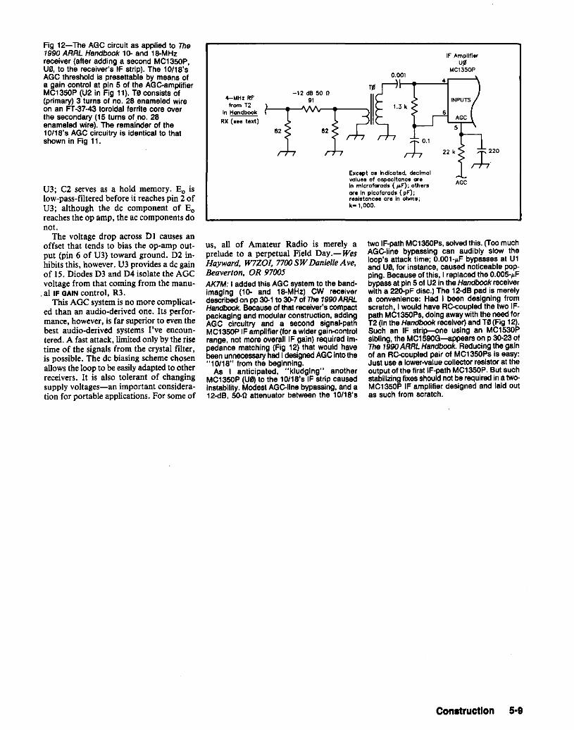
IF AmplifierU,MC1350P
ACC
22 k;h0l
O.O~Ol~__..if__\
two IF-pathMC1350P., solved this, (ToomuchAGC-lIn. bypa••'ng can audibly "ow theloop'. attack ttme: O.OOl-.F bypa•••• at Uland US,forinstance, caused noticeable popping. Because of this, I replaced the O.OO5-.Fbypassat pin 5 of U2 in the Handbookrec.iv.rwith a 22Q-pF dlsc.) The 12-<1B pad i. merelya convenience: Had I been designing fromscratch, I would have RC-coupl.d the two IFpath MC1350P., doing awaywith the need forT2 (In the Handbookrec.iv.r) and T0(Flg 12).Such an IF strip-<>n. u.'ng an MC1530P.Ibling, the MC159OG-app.ars on P 30-23ofTha 1990ARRLHandbook. Reducing the gainof an RC-coupl.d pair of MC1350P. I••asy:Just usea lower-value collector resistor at theoutput of the first IF-path MCl350P. But suchstabilizing fixes should not berequired ina twoMC1350P IF ampllfi.r d••ign.d and laid outas such from scratch.
Except a_ Indicated. decimalvalues of capacitance areIn microfarads ( ~F'); othersare In picofarads ( pF');resistances are In ohml;k-l,OOO.
-12dB50n91
82 82
4-I.tHz RFfrom T2
In Hondbook
RX (_ee text)
us, all of Amateur Radio is merely aprelude to a perpetual Field Day.- WesHayward, W7Z0I, 7700SW DanielleAve,Beaverton, OR 97005AK7M: I added this AGC syst.m to the band·imaging (10· and 18-MHz) CW rec.iv.rd.scribed on pp 30-1 to 30-701 The 1990ARRLHandbook. Because01that receiver'. compactpackaging and modular construction, addingAGC circuitry and a ••cond .Ignal·pathMC1350PIF ampllfiar (for a wld.r gain-controlrang., not more ov.rall IF gain) rsqulred Impsdance matching (Fig 12) that would havebeen unnecessaryhed I designedAGCinto the"10'18" from the beginning.
A. I anticlpated, "kludglng" anotherMC1350P (U0) to tha 10118'. IF strtp causedin.tability. Mod••t AGC-lIn. bypassing, and a12.dB, 50-0 attenuator b.tw••n the 10'18'.
Fig 12-The AGC circuit as applied to The1990 ARRL Handbook 10- and la-MHzreceiver (after adding a second MC1350P,U0, to tha r.c.,v.r'. IF strlp]. rne 10/18'.AGC threshold is presettable by means ofa gain control at pin 5 of the AGC-ampllfi.rMC1350P (U2 in Fig 11). T0 conslsts of(primary) 3 turn. of no. 28 enameled wireon an FT-37-43 toroidal f.rrlt. cor. overthe secondary (15 turn. of no. 28enameled Wire). The remafnder of the10/18's AGC circuitry is identical to thatshown in Fig 11.
U3; C2 serves as a hold memory. Eo islow-pass-filtered before ii reaches pin 2 ofU3; although the dc component of Eoreaches the op amp, the ac components donot.
The voltage drop across Dl causes anoffset that tends to bias the op-amp output (pin 6 of U3) toward ground. D2 inhibits this, however. U3 provides a de gainof 15. Diodes D3 and D4 isolate the AGCvoltage from that coming from the manu
.al IF QAIN control, R3.This AGC system is no more complicat
ed than an audio-derived one. Its performance, however, is far superiorto even thebest audio-derived systems I've encountered. A fast attack, limited only by the risetime of the signals from the crystal filter,is possible. The de biasing scheme chosenallows the loop to beeasilyadapted to otherreceivers. It is also tolerant of changingsupply voltages-an important consideration for portable applications. For some of
Con.tructlon 5·9
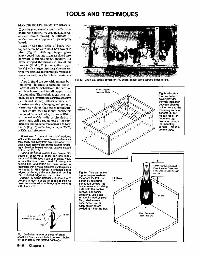
TOOLS AND TECHNIQUES
Fig l3-Zack Lau holds covers on PC-board boxes using tapped cross strips.
Fig 14-lnsettingthe box bottomcover providesthermal insulationbetween circuitryin the box and themounting surfacebeneath it, andmakes room forfasteners thatprotrude throughthe mountingsurface. This is abottom view.
Solder
Screw Protrudes Enough toPoss Through Covel'" andFUll)' Engage Lock Washerond Nut
-l_
tHead Remowdfrom ThIs End
Drilled, ToppedMounting Strip
Fig 16-You can makehigher-torque solder-infasteners for PC-board PC-Boordboxes by soldering Stockbeheaded screws intobox corners and drivingnuts onto the captivescrews. For easiersoldering, use brassscrews instead of steel,file plated screws tobase metal, and tineach screw beforesoldering it into the box.
InsetBottom
MAKING BOXES FROM PC BOARD
o As the uncontested expert staff circuitboard-box builder, I've accumulated several ideas toward making the ultimate RFmodule out of copper-clad, glass-epoxyboard.
Idea I: Use thin strips of board withtapped screw holes to hold box covers inplace (Fig 13). Although tapped glassepoxy board is not as strong as plated steelhardware, it can hold screws securely. I'venever stripped the threads in any of myprojects. (If I did, I'd just retap the strippedhole[s] with a larger tap size.) You can easily move strips to accommodate misplacedholes; for reallymisplaced holes, make newstrips.
Idea 2: Build the box with an inset bottom cover-in effect, a partition (Fig 14).Leave at least t,4 inch between the partitionand box bottom and install tapped stripsfor mounting. This technique can help thermally isolate temperature-sensitive circuitry(VFOs and so on), allows a variety ofchassis-mounting techniques, and seems towaste less volume than other techniques.
Idea 3: It's easy to mount connectorsthat need D-shaped holes, like some BNCs,to the solderable walls of circuit-boardboxes. Just drill a round hole of the rightdiameter and solder a wire across it to formthe 0 (Fig 15).-Zachary Lou, KH6CP,ARRL Lab Enginner
More ideas: Soldered-in nuts don't work toowell as PC-board-boxcover fasteners becausethey easily pull away from box walls when theirassociated screws are driven beyond fingertight. Solution: Make the screw captive insteadof the nut (Fig 16).
Cutting the board is easy if you have a PCboard or sheet-metal shear, but how manyhams do? N1FB uses a pair of tin snips, NJ2lscores the board and breaks it along thescored line, and WJ1Z has been known tolabor long with a metal nibbler to cut the pieceshe needs. N1FB finished tin-snipped boardedges by placing a file in a vise and runningthe PC-board edges across the file.
Handle PC-board material with care. Don'tbreathe its dust, handle its edges as little aspossible, and wash your hands after workingwith it.-WJIZ
Hole 101'"Connector Bushing
Fig 15-Solder a wire or piece of brasssheet across a round hole to make 0 holesfor connectors with flatted bushings.
5·10 Chapter 5

USE IC SOCKETS TO PRESERVEPLUG-IN BREADBOARDSo Fig 17shows an inexpensiveDIP socketused to preserve the holes of a plug-inbreadboard fixture. I have found thatheavyuse weakens the contact clipsin suchboards. (Some of my older boards nolonger grip wiresmaller than no. 16AWG.)An inexpensive DIP socket protects theexpensive plugboard from excessive wear.When the socket no longer provides goodcontact, simply replace it with a newone.-David Polen, W8FRB, Canton,Ohio
Fig 17-WBFRB uses a DIP socket toprolong the life of his plug-in breadboards.
IDENTIFYING IC PINOUTS ONCIRCUIT BOARDSo Building IC projects on perforatedboard can be frustrating because deviceidentity. orientation and pinout areconfusing on the wiring side of a board.Troubleshooting a perf-board Ie project isdifficult for the same reason. My solutionto this problem requires only a piece ofmasking tape for each IC, a pocketknifeand a pen or pencil. The description of thetechnique assumes that the IC to beidentified has already been placed on theboard.
Cut a piece of masking tape slightlylonger than the footprint of the IC. Usingthe pocketknife blade, push the tape downover the IC pins until it sticks to the board.Run the sharp edge of the knife blade alongthe IC pins to smooth the tape, and finishthe job by passing the unsharpened edgeof the blade between the I'C pins to ensurefirm adhesion. Next, write the IC'sfunction and pin numbers on the tape. Iusually identify only the corner pins of thechip-pins I, 7, 8 and 14 for a l4-pindevice, for instance.-Gene Shapiro.WDDLQ Prairie Village, KansasEditor's Note: So acute are the problems of icpinout and identification in the construction ofcomplex digital prototypes that a number ofmanufacturers now offer preprinted identificationtags that can be slipped over the pins of wire-wrapIC sockets. (One such product is the Wrap-ID,manufactured by OK Industries, Inc.) Becausethese tags are intended for wire-wrap use, theymay not withstand soldering heat. Nonetheless,wire-wrap identification tags may be worth investigating for soldered projects, especially forcircuits containing many ICs.
DOUBLE-STICK TAPE KEEPS COILWINDINGS IN PLACEo Before I began rewinding a coil for mydip meter, I wanted to make sure the turnswould stay in place as I wound the coil. Thenecessary inductance required many turnsof small-diameter wire, and I didn't wantthe winding to loosen and scramble if Idropped the coil during the windingprocess.
To keep the turns in place, I wounddouble-stick transparent tape on the coilform before beginning the winding. Eventhough I relaxed my pull on the wire severaltimes during the winding process, the turnsstayed put I-James Herb, W3SHP,Selinsgrove, Pennsylvania
TIDBITS FOR THE STATIONAND SHOPo Kodak" sells 35-mm photographic filmin 50- and 100-ft bulk packs, which comein tin-plated steel cans suitable for smallelectronic projects. The l00-ft can is about4 (diam) by I % inches deep, while the 50-ftcan is about 3% (diam) by 1-5/8 inches.The cans are easily soldered, and the 50-ftcan nests inside the loo-ft can. Paint thecans to prevent rust.
• You can add a spring-open feature topliers not so equipped by the maker. Spreadthe tool handle fully open, clean the insidesof the handles near the pivot and place abig dab of silicone caulk there so that itcontacts both handles. Once the plasticcures, it will cause the handles to springback to the open position. If the returnaction is too strong, cut a "V" in the caulkand remove some of the material.
• I affixed a sponge to myUngar" soldering-iron holder by putting aloop of no. 22 AWG wire through both thesponge and the holes in the holder legs.
• "Travel Pak" QSL labels are handy forlabeling your radio gear. They are inexpensive and can easily be placed anywherelike inside a hand-held (transceiver) batterypack or a cabinet. I use the same labels toidentify camera gear and other valuables.- Timothy N. Colbert, Burton, Ohioo You can straighten short pieces ofkinked-up wire by placing one end of thewire in a vise and the other in the chuckof a variable-speed hand drill. Then turnthe drill motor slowly while holding tensionon the wire. When done, polish the wirewith steel wool and give it a coat of clearacrylic paint. I've used pieces of no. 8 andno. 10 AWG wire straightened by thismethod for VHF whips.-Harold F.Keenan, KAIFJR, Danbury. Connecticuto Loose coil slugs can be tightened byremoving the slug and trapping a shortpiece of rubber band between the slug andhole as the slug is screwed back into thehole.-Boris Golovchenk:o, KB2TN,Delray Beach. Floridao A handy solder dispenser can be madefrom a container used for 35-mm
photographic film. Wind a coil of solderto the appropriate size using a screwdriverhandle as a form. Punch a hole in thecontainer cap, insert the coil in thecontainer and feed a few inches of solderout through the hole in the cap. I have anumber of these containers-each containsa different size Or formulation of solder ..-Hal Simmerman. KE40R, Marietta,Georgiao Empty Solder wick" spools makeexcellent dispensers for small-diametersolder.Just pull a few feet from a large roll and windit on the empty spool.-David A. Brown,W6NBM, Wildomar. Californiao Fishing-tackle stores sellplastic float beadsthat are good element tips for home-builtantennas. Simply heat the end of the elementand push it halfway through the bead. Theplastic beads can't prevent corona dischargelike a metal ball, but they do prevent injuriesfrom sharp element ends.-Jack Demaree,WB90TX, Versailles, Indiana
PIN MARKINGS FOR COMPUTERCONNECTORSo DB25 and similar computer-cableconnectors have molded-in pin numbers,but the labels are difficult to read. You canincrease the visibility of the numbers byrubbing a pencil or ballpoint pen overthem. [A fine-tip, permanent marker workswell, too.-Ed.] This hint was suggested tome by Tom Gilmer, my system managerand occasional "Elmer." -John V.Hedtke, KD7WS, Seattle, Washington
KEEPING TRACK OF SCRAP WIRELENGTHSo By winding moderate lengths of wire Onan 8-inch-diam form, it is easy to know theapproximately total length of the wire (infeet) just by counting the number of turnsand multiplying by 2. (Each turn is slightlylonger than 2 ft, because the circumferenceof a circle is equal to 1f [about 3.1416]multiplied by the circle's diameter.) I dothis before putting wire away for storagein the junk box by using an 8-inch kitchenpot as a temporary coil form. -James A.Herb, W3SHP, 23 E Pine Sr, Selinsgrove,PA 17870
GAUGE FINE WIRE SIMPLYo As an alternative to using a micrometeror dial caliper close-wind 10 to 20 turns ofthe wire, (how many turns doesn't matteras long as you know the number) on apencil and measure the length of thewinding. Calculate the number of turns perinch and check The 1990 A RRLHandbook's Copper Wire Table for thewire gauge that matches this turns-per-inchfigure.-Zack Lau, KH6CP, ARRLLaboratory Engineer
HOW TO STRIP LIGHT-GAGEENAMELED WIREo The small wire wheels available forhobby motor tools can be used to "skin"
Construction 5-11

l1Doug DeMaw, "Homemade Circuit BoardsDon't FearThemJ," OST, Aug1987. pp 14-16.
lCSOCKET
MAIN BOARD
SOLDERED /JUMPER WIRES
GRIOOEDSUB - BOARD(GLUE TOMAIN BOARD)
-,~-~,I,
- J-'----.::..LLj---":.Jl_=lJ,--.::::...--l
a countersink. An end mill is fast. accurateand cheap. In addition, an end mill is lesslikely to damage a PC board by overdrilling (Fig 18B).
You can make an end mill simply byusing a grinding wheel to grind off thepoint of a standard 1/8- or 3/16-inchdiameter drill bit; The result is a flat-endedbit. I suggest modifying an inexpensivedime- or hardware-store bit; these are easierto grind. (Don't even consider using acarbide bit. of course!)
When your homemade end mill showssigns of dulling (burrs instead of cleanremoval of PC-board foil). you can resharpen it easily: Just touch it up quicklywith the grinding wheel.
I've used this method successfully foryears to make test boards in a researchlab-not because end mills aren't available,but because ground-down drill bits aremuch less likely to walk off in someone'spocketi-Dick Edwin, KD2FU, Northport,New York
BLENDING CIRCUIT-BOARD FABRICATION TECHNIQUES FOR SUCCESS
o In his August 1987article on homemadecircuit boards, I I Doug DeMaw mentionedthe unsuitability of mechanically etchedboards for use with ICs or othercomponents with close pin spacings.(Generally, mechanical etching isn't preciseenough to make traces suitable for theO.I-inch pin spacing standard with l'Cs.)I've been getting around this limitation bymaking a gridded sub-board for the IC andmounting to the main (mechanicallyetched) circuit board with the piggybackmethod described in Doug's article (see Fig19). Jumper wires connect the Ie sub-boardpads to the main circuit board; glue holdsthe IC subassembly in place.-John Evans,K3SQO, Box 84, RD #1, Kingsley, PA18826
Fig 19-John Evans gets around theincompatibility of mechanically etchedboards and ICs by mounting his ICs ongridded, single-sided sub-boards. (Here,the main board Is also gridded for clarity.)The sub-boards are mounted to the mainboard using the piggyback techniquedescribed by Doug DeMaw_ See text,
GROUND-PLANE DRILL OUTgi"'" _m"""
COPPER PAD J~MATERIAL
THROUGH HOLE
IBI
(AI
condition when I get it; sometimes, itrequires a new bulb. Major surgery mightinvolve replacing the lamp's line cord.Used-lamp goosenecks are almost alwaysin good shape; a loose rivet-joint gooseneckcan be quickly and easily repaired with no.4-40 hardware.
If you're worried about your lamp'sgooseneck or reflector coming into contactwith a bare live conductor, a wrap of plasticelectrical tape insulates things nicely.
Finally-although I haven't tried this-acouple of magnets, epoxied to the lampbase-should hold the lamp to a steelsurface. should the need for this arise.-Julian N. Jablin, W9IWI, 9124 NCrawford A ve, Skokie, IL 60076
USE AN END MILL TO REMOVECOPPER FROM PC BOARDS
o In some cases, the stability ofRF PCboard circuitry can be enhanced by usingthe component side of a double-sided boardas a groundplane. This constructionmethod requires an extra step. however,because copper must be removed aroundcomponent-lead holes to avoid shortcircuits to the groundplane. A drawing ina January 1985 QST article'? showshow to do this with a drill or countersink(Fig 18A).
For me, the easiest method of doing thisis to use a homemade end mill rather than
Fig 18-When you use one side of adouble-sided PC board as a groundplane,the ground-plane copper must be removedaround each through-hole. You can removethe foil with a drill or countersink (A), butoverdrilling with these tools can easily ruinthe board. An end mill allows removal offoil with little or no damage to the underlying board material (B). Dick Edwinsuggests using a homemade end mill;see text.
riO"'''"'COPPER\ WITH END MILL
COPPER PAD.-/""J~MATERIAL
THROUGH HOL E
10Jonathan F. Towle, "A Simple 10-Meter FMReceiver," QST, Jan 1985, pp 19-21.
small-diameter stranded wires. (Standard.designed-for-application skinning devicesare apt to break Or cut some strands.)Simply place the wire up against a fairlyhard surface (a block of wood will do) andwire-brush the insulation off.-WillardBridgham, WI WF, Box 103, Windsor, MA01270WINDING LARGE COILS ON AMOTORIZED BARBECUE SPIT
o Evenly winding large coils of no. 16 orheavier-gage wire can be tricky. Such a jobmay require three hands! Winding evenlyspaced coils with lighter-gage wire is alsoa chore, even if you use string for spacingthe turns. Winding such a coil ofteninvolves several tries. and the result rarelylooks professional.
I wind large coils on a motorized barbecue spit with a set of mandrels made fromplastic irrigation tube. End washers, madefrom PC-board material and cut to fit thesquare spit, cap the mandrels. "Instant"glue holds the washers to the mandrels.
This arrangement allows me to windlarge coils for power-amplifier tanks,Transmatches, and so on. from wire up tono. 12. For air-core, self-supporting coils,I use a mandrel ~ inch less in diameterthan the final diameter of the coil. Themotor is slow enough for the turns to bewound against firm thumb pressure belowthe rotating mandrel, which limits "springout" when the wire is cut.
Thin-wire, space-wound coils can bewound with great accuracy on slip-onforms. With patience, you can even windLitz-wire and 'IT-wound chokes. For plugin transmitter coils. 1!4-inch-diam plasticpipe couplers are fine-and cheap. Theycan bedrilled and mounted on 14-gage-wirelegs passed through two holes in a terminalstrip and soldered to form plug-in pins.
Although large, solenoidal coils are lessin vogue than they once were, they are stilluseful in antenna tuners and vacuum-tubepower amplifiers. My rotisserie techniqueallows me to fabricate such coils professionally and cheaply.-Alex Comfort, MD,KA6UXR, 121 S Evergreen, Ventura, CA93003
USE YOUR SOLDERING GUN TODEMAGNETIZE TOOLS
D If you have a screwdriver or other smalltool that's become magnetized (as mine didafter I used it to work on a magnetic-mount2-meter antenna), turn on your solderinggun and pass the tool slowly between thearms that support the soldering tip. Instantdemagnetization!-Julian N. Jablin,W9IWl, 9124 N Crawford Ave, Skokie, IL60076
INEXPENSIVE WORK LAMPS
o Work lamps need not be expensive. I buydiscarded high-intensity lamps at garage andrummage sales. There must be a half-dozenof these. most of which cost 50 cents to $1knocking around my basement. •
Usually. a given lamp is in working
5-12 Chapter 5
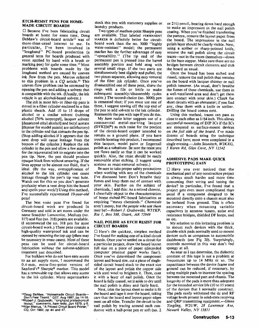
ETCH-RESIST PENS FOR HOME.MADE CIRCUIT BOARDS
o Because I've been fabricating circuitboards at home for some time, DougDeMaw's circuit-board article" was ofmore-than-usual interest to me. Inparticular, I've been involved in"longhand" PC-board production (ageneral term for boards produced withresist applied by hand with a brush ormarking pen) for quite some time. 13 Mostproblems with boards made by thelonghand method are caused by unevenink flow from the pen. Marcus referredto this problem in a CQ article." Thisuneven-flow problem can be corrected byopening the pen and adding a solvent thatis compatible with the ink. (Usually, the inkvehicle is an alcohol-based solvent.)
The ink in most felt- or fiber-tip pens isstored in a fiber cylinder enclosed in a thinplastic sheath. Add 10 to 15 drops ofalcohol Or a similar solvent (rubbingalcohol [70'70 isopropyl], lacquer solvent[denatured ethyl alcohol] and butyl acetate[thinner for model paints] are satisfactory)to the cylinder end that contacts the pen tip.(Stop adding alcohol if it appears that thenext drop will cause leakage from thebottom of the cylinder.) Replace the inkcylinder in the pen and allow a few minutesfor the rejuvenated ink to migrate into thepen tip. Now, the pen should produceopaque black lines without smearing. If thelines appear to be almost too fluid, that'sideal. (By the way, overapplication ofalcohol to the ink cylinder can causeleakage through the pen's tip vent hole.Watch out for this so you don't generateprofanity when a vent drop hits the boardand spoils your work!) Using this method,I've successfully rejuvenated ltl-year-oldpens!
The best resist pens I've found forcircuit-board work are produced inGermany and sold in art stores under thename Staedtler Lumocolor. Medium (no.317) and fine (no, 318) points are available.(I recommend the no. 318 pen for mostcircuit-board work.) These pens contain ahigh-quality waterproof ink and can beopened by removing the top cap (pliers maybe necessary in some cases). Most of these'pens can be used for circuit-boardfabrication without the solvent-additiontreatment just described.
For builders who do not have easy accessto an art supply store, I recommend theO.4-mm, extra-fine-point version ofSanford's" Sharpie's marker. This modelhas a removable top that allows easy accessto the ink cylinder. Many supermarkets
12Dou~ DeMaw. "Homemade Circuit BoardsDon t Fear Them!." QST, Aug 1987, pp 14-16.
13Robert J. Grabowski, "longhand printed-circuitlayout," comments, ham radio, Jun 1979, p 6.
14Alan Marcus, "A Printed Circuit Board Primer,"CQ, Oct 1982, pp 44 and 47.
stock this pen with stationery supplies or.laundry products.
Two types of medium-point Sharpie pensare available. That labeled PERMANENTMARKER is definitely better for circuitboard work than the no. 3000 "highlywater-resistant" model; the permanentmarker has the further advantage of easy"openability." (The tip end of thepermanent pen is pressed into the barrelassembly portion and held snug withseveral small rings. If the two parts aresimultaneously bent slightly and pulled, thetwo pieces separate, allowing easy removalof the fiber ink cylinder. Once you'vedisassembled one of these pens. shave therings with a file or knife to makesubsequent assembly/disassembly cycleseasier.) The second-choice (no. 3000) penis cemented shut; if you must use one ofthese, ] suggest sawing off the top end ofthe pen to add solvent to the ink cylinder.Reassemblethe pen with tape if you do this.
My ham radio letter suggests use of acommercial metal-marking lacquer(DYKEM"') as etch resist for the portionof the circuit-board copper intended toremain as a ground plane. If you havetrouble locating this product, I recommendthin lacquer, model paint or fingernailpolish as a substitute. Be sure the resist youuse flows easily so that it can be workedquickly. Also, the resist should be easilyremovable after etching. (I suggest usingacetone as resist-removal solvent.)
Besure to take proper safety precautionswhen working with any of the chemicalsI've discussed here: Don't breathe theirfumes and keep them out of contact withyour skin. Further on the subject ofchemicals, 1 add this: As a retired chemist,] cheerfully object to the characterizationof home etched-P'C-board fabrication asrequiring "messy chemicals." Chemicalsaren't messy, but the people who use themmay bel-Robert J. Grabowski, W5TKP,Rte 1, Box 388, Ozark, AR 72949
NAIL POLISH AS ETCH RESIST FORCIRCUIT BOARDS
o Here's the quickest, simplest methodI've found for making one-of-a-kind circuitboards. Once you've settled on a circuit fora particular project, draw the board layoutfull size on a piece of paper (discardedcomputer printout paper works fine!).Once you've determined the componentlayout and board size, cut a piece of singlesided circuit board stock to the exact sizeof the layout and polish the copper sidewith steel wool to brighten it. Then, coatit with a layer of nail polish. Once theboard is fully coated, set it aside to dry untilthe nail polish is shiny and fairly hard.
Next, trim the layout sheet to make it fitthe board and tape it over the board, takingcare that the board and layout paper edgesmeet on all sides. Transfer the circuit to thenail polish by tracing around each conductor with a ball-point pen Orsoft (no. 2
or 2Yz) pencil, bearing down hard enoughto make an impression in the nail polishcoating. When you've finished transferringthe pattern, remove the layout paper fromthe board. The impressions in the nailpolish layer should be clearly visible. Next,using a scriber or sharp-pointed knife,remove the nail polish along the circuittraces-not in the traces themselves-downto the bare copper. Make sure there are nobridges between circuit elements and etchthe board as usual.
Once the board has been etched andrinsed, remove the nail polish that remainson the board with lacquer thinner or nailpolish remover. (As usual, don't breathethe fumes of these chemicals, use them ina well-ventilated area and don't get theminto contact with your skin.) Check forshort circuits with an ohmmeter; if you findany, clear them with a knife Or scriber.Drilling the board comes next.
Using this method, traces can pass asclose to each other as 1/64 inch. This allowssuccessful mounting of DIP lCs if the ICsare mounted as surface-mount deviceson the foil side of the board. I've madedozens of boards using the techniquedescribed here; most were completed in asingle evening.-John Stonitsch, W2KXG.5 Karen Rd, Glen Cove, NY 11542
ADHESIVE PADS MAKE QUICKPROTOTYPING EASY
o Have you ever noticed that themechanical part of any construction projectis always much harder and more timeconsuming than wiring and testing thedevice? In particular, I've found that aproject gets even more complicated thanusual if a component designed to bemounted directly onto a chassis must alsobe isolated from ground. This is oftennecessary when mounting variablecapacitors in antenna tuners, noise andresistance bridges, shielded DF loops, andso on.
My solution to this irritating problem isto mount such devices with the thick,double-stick pads normally used to mountdevices such as compasses to automobiledashboards (see Fig 20). Surprisingly,controls mounted in this way don't feelspongy at all.
As near as 1can determine, the dielectricconstant of this tape is not a problem atfrequencies up to 14 MHz or so. Thecapacitance between the device frame andground can be reduced, if necessary, byusing multiple pads to increase the spacingbetween the mounted part and chassis. Thelongevityof the pads is more than adequatefor the intended service life (10 to 15years)of the devices that I normally construct.The pads easily withstand the de and RFvoltage levels present in solid-state receivingand QRP transmitting equipment.-GlennYingling, W2UW, 28 Lawrence Ave,Newark Valley, NY 13811
Construction 5·13
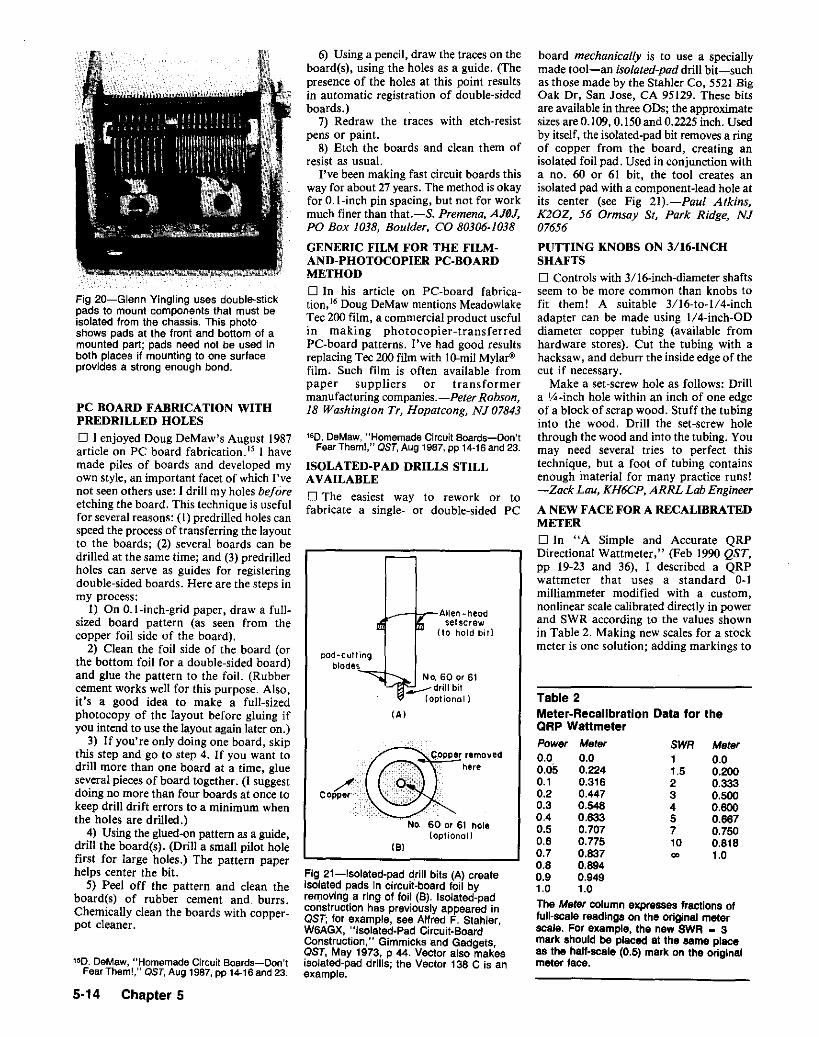
181
IAI
Meter0.00.2000.3330.5000.8000.8870.7500.8181.0'"
SWR11.52345710
board mechanically is to use a speciallymade tool-c-an isolated-pad drill bit-suchas those made by the Stahler Co, 5521 BigOak Dr, San Jose, CA 95129. These bitsare available in three ODs; the approximatesizes are 0.109,0.150 and 0.2225 inch. Usedby itself, the isolated-pad bit removes a ringof copper from the board, creating anisolated foil pad. Used in conjunction witha no. 60 or 61 bit, the tool creates anisolated pad with a component-lead hole atits center (see Fig 21).-Paul Atkins,K20Z, 56 Ormsay St, Park Ridge, NJ07656
PUTTING KNOBS ON 3/16·INCHSHAFTSo Controls with 3/16-inch-diameter shaftsseem to be more common than knobs tofit them! A suitable 3/16-to-1/4-inchadapter can be made using 1/a-inch-Of)diameter copper tubing (available fromhardware stores). Cut the tubing with ahacksaw, and deburr the inside edge of thecut if necessary.
Make a set-screw hole as follows: Drilla ~-inch hole within an inch of one edgeof a block of scrap wood. Stuff the tubinginto the wood. Drill the set-screw holethrough the wood and into the tubing. Youmay need several tries to perfect thistechnique, but a foot of tubing containsenough material for many practice runs!-Zack Lou, KH6CP, ARRL Lab Engineer
A NEW FACE FOR A RECALIBRATEDMETERo In "A Simple and Accurate QRPDirectional Wattmeter," (Feb 1990 QST,pp 19-23 and 36), I described a QRPwattmeter that uses a standard 0-1milliammeter modified with a custom,nonlinear scale calibrated directly in powerand SWR according to the values shownin Table 2. Making new scales for a stockmeter is one solution; adding markings to
Table 2Meter·Recalibration Data for theQRP WattmeterPower Meter0.0 0.00.05 0.2240.1 0.3160.2 0.4470.3 0.5480.4 0.6330.5 0.7070.6 0.7750.7 0.8370.8 0.8940.9 0.9491.0 1.0
The Meter column expresses fractions offull-scale readings on the original meterscale. For example, the new SWR • 3mark should be placed at the same placeas the hall-scale (0.5) mark on the originalmeter face.
..___--iI7--Allen -neccsetscrew
(to hold bit)
/:Copper
No. 60 or 61 hole(optional)
160 , DeMaw, "Homemade Circuit Boards-Don'tFearTheml," OST, Aug 1987,pp 14·16and 23.
ISOLATED·PAD DRILLS STILLAVAILABLE
o The easiest way to rework or tofabricate a single- or double-sided PC
6) Using a pencil, draw the traces on theboard(s), using the holes as a guide. (Thepresence of the holes at this point resultsin automatic registration of double-sidedboards.)
7) Redraw the traces with etch-resistpens or paint.
8) Etch the boards and clean them ofresist as usual.
I've been making fast circuit boards thisway for about 27 years. The method is okayfor O.l-inch pin spacing, but not for workmuch finer than that.-S. Premena, AJfJ,J.PO Box 1038, Boulder, CO 80306-1038
GENERIC FILM FOR THE FILMAND-PHOTOCOPIER PC-BOARDMETHOD
o In his article on PC-board fabrication," Doug DeMaw mentions MeadowlakeTee 200 film, a commercial product usefulin making photocopier-transferredPCMboard patterns. I've had good resultsreplacing Tee 200 film with 10-milMylar"film. Such film is often available frompaper suppliers or transformermanufacturing companies.-Peter Robson,18 Washing/on tr, Hopatcong, NJ 07843
pod-cuttingblades
Fig 21-lsolatad-pad d!ill bits (A) createisolated pads in ctrcult-board foil byremoving a ring of foil (B). Isoiated-padconstruction has previously appeared inOST; for example, see Alfred F. Stahier,W6AGX, "lsolated-Pad Circuit-BoardConstruction," Gimmicks and Gadgets,OST, May 1973, p 44. Vector also makesisolated-pad drills; the Vector 138 C is anexample.
PC BOARD FABRICATION WITHPREDRILLED HOLES
o I enjoyed Doug DeMaw's August 1987article on PC board fabrication. IS I havemade piles of boards and developed myown style, an important facet of which I'venot seen others use.J drill my holes beforeetching the board. This technique is usefulfor several reasons: (1) predrilled holes canspeed the process of transferring the layoutto the boards; (2) several boards can bedrilled at the same time; and (3) predrilledholes can serve as guides for registeringdouble-sided boards. Here are the steps inmy process:
I) On O.I-inch-grid paper, draw a fullsized board pattern (as seen from thecopper foil side of the board).
2) Clean the foil side of the board (orthe bottom foil for a double-sided board)and glue the pattern to the foil. (Rubbercement works well for this purpose. Also,it's a good idea to make a full-sizedphotocopy of the layout before gluing ifyou intend to use the layout again later on.)
3) If you're only doing one board, skipthis step and go to step 4. If you want todrill more than one board at a time, glueseveral pieces of board together. (I suggestdoing no more than four boards at once tokeep drill drift errors to a minimum whenthe holes are drilled.)
4) Using the glued-on pattern as a guide,drill the board(s). (Drill a small pilot holefirst for large holes.) The pattern paperhelps center the bit.
5) Peel off the pattern and clean theboard(s) of rubber cement and burrs.Chemically clean the boards with copperpot cleaner.
Fig 20-Glenn Yingling uses double-stickpads to mount components that must beisolated from the chassis. This photoshows pads at the front and bottom of amounted part; pads need not be used inboth places if mounting to one surfaceprovides a strong enough bond.
150 . DeMaw, "Homemade Circuit Boards-Don'tFearThem!," OST, Aug 1987,PP14-16and 23.
5·14 Chapter 5
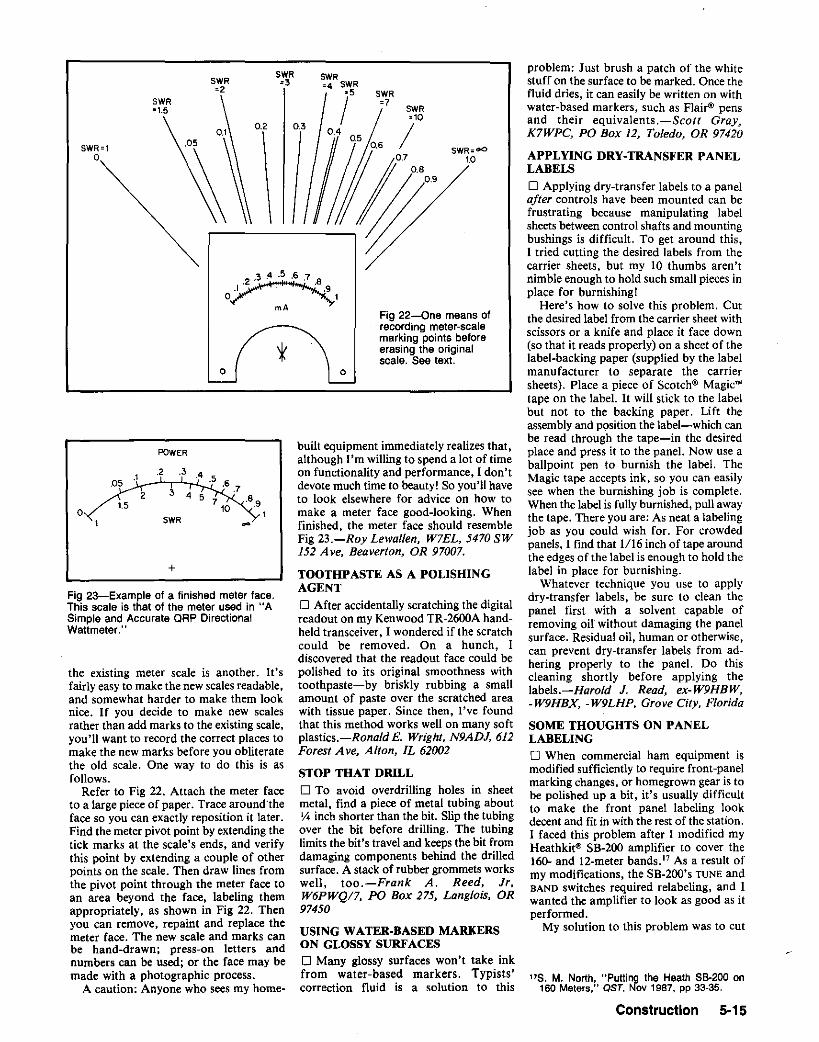
175. M. North, "Putting the Heath 58-200 on160 Meters," QST. Nov 1987, pp 33-35.
problem: Just brush a patch of the whitestuff on the surface to be marked. Once thefluid dries, it can easily be written on withwater-based markers, such as Flairv pensand their equivalents.-Scott Gray.K7WPC, PO Box 12, Toledo, OR 97420
APPLYING DRY-TRANSFER PANELLABELS
o Applying dry-transfer labels to a panelafter controls have been mounted can befrustrating because manipulating labelsheets between control shafts and mountingbushings is difficult. To get around this,I tried cutting the desired labels from thecarrier sheets, but my 10 thumbs aren'tnimble enough to hold such small pieces inplace for burnishing!
Here's how to solve this problem. Cutthe desired label from the carrier sheet withscissors or a knife and place it face down(so that it reads properly) on a sheet of thelabel-backing paper (supplied by the labelmanufacturer to separate the carriersheets). Place a piece of Scotch'" Magic"tape on the label. It will stick to the labelbut not to the backing paper. Lift theassembly and position the label-which canbe read through the tape-in the desiredplace and press it to the panel. Now use aballpoint pen to burnish the label. TheMagic tape accepts ink, so you can easilysee when the burnishing job is complete.When the label is fully burnished, pull awaythe tape. There you are: As neat a labelingjob as you could wish for. For crowdedpanels, I find that 1116inch of tape aroundthe edges of the label is enough to hold thelabel in place for burnishing.
Whatever technique you use to applydry-transfer labels, be sure to clean thepanel first with a solvent capable ofremoving oil without damaging the panelsurface. Residual oil, human or otherwise,can prevent dry-transfer labels from adhering properly to the panel. Do thiscleaning shortly before applying thelabels.-Harold J. Read, ex-W9HBW,-W9HBX, -W9LHP, Grove City, Florida
SOME THOUGHTS ON PANELLABELINGo When commercial ham equipment ismodified sufficiently to require front-panelmarking changes, or homegrown gear is tobe polished up a bit, it's usually difficultto make the front panel labeling lookdecent and fit in with the rest of the station.I faced this problem after I modified myHeathkit'" 5B-200 amplifier to cover the160- and 12-meter bands." As a result ofmy modifications, the 5B-200's TUNE andBAND switches required relabeling, and Iwanted the amplifier to look as good as itperformed.
My solution to this problem was to cut
Fig 22-0ne means ofrecording meter-scalemarking points beforeerasing the originalscale. See text.
o
built equipment immediately realizes that,although I'm willing to spend a lot of timeon functionality and performance, I don'tdevote much time to beauty! So you'll haveto look elsewhere for advice on how tomake a meter face good-looking. Whenfinished, the meter face should resembleFig 23.-Roy Lewallen, W7EL, 5470 SW152 Ave, Beaverton, OR 97007.
TOOTHPASTE AS A POLISHINGAGENT
o After accidentally scratching the digitalreadout on my Kenwood TR-2600A handheld transceiver, I wondered if the scratchcould be removed. On a hunch, Idiscovered that the readout face could bepolished to its original smoothness withtoothpaste-by briskly rubbing a smallamount of paste over the scratched areawith tissue paper. Since then, I've foundthat this method works well on many softplastics.-Ronald E. Wright, N9ADJ, 612Forest Ave, Alton, IL 62002
STOP THAT DRILL
o To avoid overdrilling holes in sheetmetal, find a piece of metal tubing aboutV. inch shorter than the bit. Slip the tubingover the bit before drilling. The tubinglimits the bit's travel and keeps the bit fromdamaging components behind the drilledsurface. A stack of rubber grommets workswell, too.-Frank A. Reed, Jr.W6PWQ/7, PO Box 275, Langlois, OR97450
USING WATER·BASED MARKERSON GLOSSY SURFACESo Many glossy surfaces won't take inkfrom water-based markers. Typists'correction fluid is a solution to this
t
SWR SWRSWR -3 :4 SWR-2 -5 SWRSWR I -7
SWR"1.5=10
0.2 0.30.4 /0.5
SWR=1 SWR=oO0 1.0
POWER
.2 .3 ...1. .505 .6.72 3 • 5 .8.91.5 7
' 00 1SWR -+
the existing meter scale is another. It'5
fairly easy to make the new scales readable,and somewhat harder to make them looknice. If you decide to make new scalesrather than add marks to the existing scale,you'll want to record the correct places tomake the new marks before you obliteratethe old scale. One way to do this is asfollows.
Refer to Fig 22. Attach the meter faceto a large piece of paper. Trace aroundtheface so you can exactly reposition it later.Find the meter pivot point by extending thetick marks at the scale's ends, and verifythis point by extending a couple of otherpoints on the scale. Then draw lines fromthe pivot point through the meter face toan area beyond the face, labeling themappropriately, as shown in Fig 22. Thenyou can remove, repaint and replace themeter face. The new scale and marks canbe hand-drawn; press-on letters andnumbers can be used; or the face may bemade with a photographic process.
A caution: Anyone who sees my home-
Fig 23-Example of a finished meter face.This scale is that of the meter used in "ASimple and Accurate QRP DirectionalWattmeter.' ,
Construction 5·15

(A) (B)
Fig 24-Safford North relabeled his 88-200 amplifier without modification by using a labeled pasteboard subpanal. Installation is easy:The slotted pasteboard just slides into place behind the amplifier controls.
a rectangular piece of black pasteboardlarge enough to cover the scales around theSB-2oo's LOAD, TUNEand BAND controls.I used white ink to draw the band arcsaround the TUNE control and white drytransfer lettering for the LOAD and BANDscales, and for labeling the band arcs (Fig24A).
With suitable slots cut to pass the LOAD,
TUNE and BAND control shafts, the labeledsubpanel slides neatly into place on theSB-200 (Fig 24B). The white-on-blackappearance of the subpanel is striking andthe controls are properly labeled-allwithout modifying the equipment frontpanel itself in any way.-Sajjard M.North, KG2M, 1426 Riverbend Dr,Baldwinsville, NY 13027
~MATTE FINISH AND PANEL LABELSFOR HOMEMADE PROJECTS
o When we construct a radio/electronicsdevice and put it in a box, its front paneloften ends up looking shabby, withhandwritten names for control labels. Anice-looking front panel reflects the qualityof the project inside the box. Here is asimple way of making an attractive frontpanel that has a matte-finish silver hairlinedesign. If your project box already has analuminum front panel, great. If not, cut analuminum plate the same size as the box'sfront panel and attach it to the box. Beforebeginning, make all necessary holes andcuts in the front panel(s).
Step 1. Wrap fine sandpaper around apiece of wood and sand the aluminumpanel in one direction until fine hairlinesbegin to appear. If the panel is coated withpaint, be patient and do this until the paintcomes of! and the hairlines appear.
Step 2. Thoroughly clean the panelsurface. Now, spray the panel with clearlacquer paint. The purpose of this is tomake the surface of the panel smooth forapplying dry rub-on lettering. Wait untilthe lacquer dries completely, then apply thelettering.
Step 3. Spray the panel with clear enamelpaint. (Important: Use a different type ofpaint than you used in Step 2. Otherwise,this coat may mix with the Step 2 paint,causing the lettering to float around in a
5-16 Chapter 5
sea of clear paint!) Spray a few coats untilthe paint completely covers the lettering.
Step 4. Heat the front panel from behindthe painted side until it is almost too hotto touch. You can do this over a gas stove,but becareful to keep the painted side frommaking direct contact with the flames.Remove the panel from the heat source andimmediately spray on another coat of clearenamel from some distance away (l footor more), so that the paint particles landon the panel spread widely apart. As thepanel cools, the paint particles will shrink,giving a matte finish on the panel.
This is not an original idea, butsomething I learned back in Tokyo manyyears ago when I was a kid, making a lotof projects and looking for neat ways ofmaking a good-looking front panel, I hopethis technique gives you a handsome frontpanel that the device inside the box trulydeserves!-Kunio Mitsuma, KA3RRF,Calder Sq, PO Box 10407, State College,PA 16805
SOLDERING TO STAINLESS STEELALMOST
o Stainless steel doesn't take solder, butthe equivalent of a soldered connection canbe made to stainless steel by means of awelding technique. Using an oxyacetyleneor Mappw gas torch, braze a patch of brassto the steel. Solder your connection to thebrass instead of the steel. If you use thistechnique for connection to a stainless steelclamp on an aluminum antenna element,be careful not to allow contact. between thebrass and the aluminum: corrosion canresult where t.hese metals touch.-Edson B.Snow, W2UN, Pompano Beach, Florida
H & K INTERACTION: SOLDERINGTO STAINLESS STEEL
In "Soldering to Stainless Steel-Almost,"Edson B. Snow, W2UN, described amethod of welding a brass patch (eminentlysolderable) to stainless steel (difficult tosolder). In response to this, readers write:o I've been soldering to stainless steel forover 20 years, achieving structurally soundjoints that compare favorably with jointsin iron or brass. There's no trick to it. Atone time, I used a special paste flux, but
now I use ordinary zinc chloride/hydrochloric acid liquid flux, available athardware stores. Bar solder (40% tin, 600/0lead) or rosin-core wire solder works well.
The metals to be soldered to must beclean. Tin each piece separately, then clampor otherwise hold the pieces together. Next,heat the work and flow solder into thejoint.
For joining thick pieces of stainless-steelat right angles, I clamp them securely intoposition (after tinning), carefully preheatthe parts with a propane torch (taking carenot to discolor the metal) and finish the jobwith a large soldering iron. This methodallows me to pile up enough solder to formfillets that greatly strengthen the joint.-Ed Nickerson, K4EBF, 610 NYachtsman Dr, Sanibel, FL 33957o Ed Snow's H & K note on solderingstainless steel prompted me to look up thesolders I've been using. Stay-bright'(manufactured by the J. W. Harris Co, Inc)or Kester" "Sit-Strong" (4% silver, 96%tin) solder will do an excellent job onstainless steel and many other metals. "SilStrong" melts at 430 OF and can be appliedwith a regular soldering iron; it's alsoclaimed to be five times stronger thanregular tin-lead solder-a statement that,according to my experience, seems to betrue.
I found both products at my localhardware store. They're more expensivethan regular soft solders, but since they dothe job, they're worth the price.-BillCorse, K3YSL, PO Box 125, NewFreedom, PA 17349o ,Fabricators of kitchen equipment findstainless steel to be one of the easiest metalsto solder. The secret is to use the properflux. A number of such fluxes are availableon the market, and these can be obtainedat sheet-metal supply houses. I useLloyd'sstainless-steel flux, which is manufacturedby the Johnson Mfg Co, Princeton, IA52768. (Although my name is Lloyd, I haveno connection with this company.} I've hadno problems with corrosion of the solderedjoints; just be sure to rinse or wipe the workclean with a damp rag when finished.-Lloyd Franklin, W9WUR, 8006 SKirkland A ve, Chicago, IL 60652

SOLDERING TO STAINLESSSTEEL-AGAIN
o Concerning "Soldering to StainlessSteel-Almost": I've successfully solderedstainless steel to stainless steel-and to iron,cast iron, brass, copper and other metalsby using homemade acidic soldering fluxmade of the following ingredients: 37 g ofzinc chloride, 23 g of glacial acetic acid and40 g of hydrochloric acid. (This formulaproduces a considerable quantity of flux;you can scale down the quantities inproportion to suit your needs.) To makethe zinc chloride, I dissolve zinc in hydrochloric acid until the solution is saturated;then I carefully add the rest of theingredients.-Roger Del Nero, WA2HNQ,RFD #6, Box 291, Rome, NY 13440AK7M:This formulacalls forchemicalsthat arehazardous to touch and breathe. Hints andKinksrecommends that readers unsureof theirability to handle dangerous chemicalspurchase ready-to-use zinc-chloride fluxinstead of trying to blend their own.Preformulated acidic fluxes are hazardous,too; use them carefully.
RE·CEMENTING TUBE GRID ANDPLATE CAPSo When the ceramic adhesive that holdsa plate or grid cap to a tube breaks awayfrom the tube envelope, making aconnection to the loose cap can strain theterminal's metal-to-glass seal and wire. 1successfully reattached a loose cap to an811A with high-temperature stove-gasketcement. (I use a cement manufactured by
Rutland; I bought it at a hardware store.)If the cap is still properly soldered to the
terminal wire, skip to the next paragraph.If the cap has come loose from the tube andterminal wire, carefully clean the wire,sanding it (if necessary) so solder canadhere. Resolder the cap to the wire.
Following the manufacturer'sinstructions for handling and applying thecement, push the cement under the capedge to fill the tube-to-cap gap as fully aspossible. Prop up the tube while the cementsets.
Tube heat apparently helps the cementcure, so using the tube may furtherstrengthen the cement-to-glass bond. Sofar, the cap 1reattached this way has stayedpUL-Jay Bryant, KM41M, 4736DauphineBlvd, Tallahassee, FL 32803
WHEN FUSES SHATTER
o In the courseof performingtheir function,tubular glass fuses may shatter if subjectedto a severe overload. This causes twoproblems: (1) glass shards in the holder and(2) the detached fuseend cup insidethe holderbase. These remnants can usually be ejectedby inserting a small rod through the back endof the holder if that end of the holder isaccessible.
These problems can be minimized bywrappingthe glassbody of the fusewithvinyltape. One or two turns are enough; ~-in-widetape is a perfect fit on standard size fuses(3AG, and so on). Use transparent tape toallow visual inspection of the fuse element.
If the back cup of a disintegratedfusecan't
be pushed or pulled from the holder by othermeans, here's an adhesivesolution: Put a dabof mixed five-minute epoxy glue on thepassive end of a wooden match. Carefullyinsert the matchstick into the fuse holder,glued end first. When it bottoms, twist itgently, but firmly, to seat it in the fuse endcup. Allowthe epoxycementto cure for ]()"15minutes and pull out the matchstick, If yourecover only glass fragments, repeat the procedure until the errant cup is extracted.-Marty, W6BDN,and Dan, N6BZA, Levin,Menlo Park, California
USING HEAT AND COLD TO MOUNTPARTS
o A remembered high-school physicsdemonstration helped me replace the tip onmy collapsible 5/S-wave hand-held transceiver antenna. I'd pulled the original tiploose and lost it. The replacement tip sentto me by the factory apparently had beenmade for a different antenna: The socketfor the antenna was too small.
I enlarged the socket with a drill one sizesmaller than the antenna tip. Then I put theantenna in our food freezer for a coupleof hours. Next, I heated the tip in a400 0 F oven for 15 minutes. Taking propercare not to be burned by heat or cold, Itried to assemble the parts again. Voila!Shrunk by cold, the antenna slipped intothe heat-enlarged hole of the tip. As theparts reached the same temperature, theantenna swelled slightly and the tip shrank,resulting in a press fit as strong and tightas a weld.-Richard Ellers, K8JLK,Warren. Ohio
Construction 5·17

REPLACEMENT PA TRANSISTORS
o With winter here, I would like to passsome practicaladvice along to ownersof theKenwood TS-130. On a winter day inJanuary 1983, I had left my mobile rig outin the cold for several hours at about OQF.When I switched the rig on, the collectorcurrent rose to a very high value, and oneof the PA transistors developed an emitter/ collector short. I checked with an RF engineer and found that this is common failuremode for RF power transistors that areseveral years old. He suggested that I avoidthis problem in the future by warming therig to about 20° before applying power.
I replaced the original Toshiba 2SC2290s18
with a pair of matched Motorola MRF4215, whichare listedas direct replacementsin the Motorola manual. The replacementprocedure is very straightforward: Simplyinstall the new transistors and adjust thebias current as described in the shopmanual. The results are excellent, and thenew transistors produce slightly morepower than the originals on 10 and15 meters. These transistors have been inservice for about three years now, with nosigns of instability or other problems.George Hovorka, WA1PDY, Milton,Massachusetts
18[These same PA transistors are used Inmany contemporary radios as well, such asthe TS-430S.-Ed.1
TRANSISTOR HEAT SINKS FROMALUMINUM TUBING
D Here are two alternatives to forming
3/8" 00
~PEN . SE AM ALUMINUM
TUBING
TO SLIP SINK OVERT.RANSISTOR, INSERTa.. SCREWDRIVER HERE AND TWIST
~I~ <, TO-5 DR -39 TRANSISTOR
SIMPLE CYLINDRICALHEAT SINK
IA)
r-~,I ,, ,L_ _J
CUT HALF WAY THROUGHTUBE AND BEND TUBE OUT
(B)
FINISHED HEAT SINK
HEAT SINK WITH BETTEREXPOSURE TO ALR
Fig 25---W6SPC's quick TO-srrO·39 heatsinks from open-seam, 3/8-inch-ODaluminum tubing.
5-18 Chapter 5
PARTSsmall heat sinks on a vise. Each makes useof open-seam, 3/8-inch-OD aluminumtubing. See Fig 25A. Cut the tubing tolength, and clean the cut with reamer andfile. Pry open the seam with a screwdriverand slip the sink over the transistor. Thesink shown in Fig 25B uses the same technique, but is more open to the air. The3/8-inch tubing is just right for transistorsin TO-5 and TO-39 cases.-Daniel G.Mackintosh, W6SPC, San Francisco,California
REDUCTION-DRIVE TUNINGCAPACITORS FROM UHF TVTUNERS
o Surplus UHF TV tuners, and those indiscarded TV sets, may serve as a source ofreduct:ion-drive tuning capacitors. The gearedreduction drives on these variable capacitorshave practically no backlash. After you havelocated such a tuner, carefully open it. Youshould see a tiny three-section variablecapacitor with an integral reduction drive.Depending on when the tuner was manufactured, it may havea detent systemfor channelselection. If such a systemis present. removeor otherwise disable it.
Now, let your creativity be your guide. Inone project, I disconnected the capacitorstators from the tuner circuitry, wired themtogether and brought a lead from theparalletled stators out through a hole in thetuner box. I kept the tuner knobs and usedthem to adjust the capacitor .-James Smith,KD4YD, Ellenton, Florida
REPAIR VARIABLE CAPACITORSWITH PLASTIC SHEET
o I bought a homemade L-network Transmatch at a recent hamfest only to discoverlater that the ceramic insulation of itsvariable capacitor was badly cracked. AfterI overcamemy disappointment. I noticed thatthe capacitor could be disassembled; it washeld together with screws rather than rivets.I measured the thickness of the broken insulator (1,4 inch), and headed to a hardwarestore to find replacement material.
Fifty cents' worth of scrap lI8-inchPlexiglas" provided the solution. Using theceramic pieces from the capacitor as atemplate, I marked and drilled two identical Plexiglas pieces to bring the thicknessof the replacement assembly to '4 inch.Even though I had to make several tries atsizing the pieces because of my inexperiencewith tools, the rebuilt capacitor works! Thishint may help others save damaged variable capacitors that cannot be replacedeasily or cheaply.-Oscar Martinson.NfJDKB, Minneapolis. Minnesota
IMPROVED PERFORMANCE INOLDER VARIABLE CAPACITORS
o I read with interest N0DKB's capacitorrepair hint and decided that replacing withacrylic plastic the bakelite insulation insome of my older capacitors (those used insituations where appearance and authenticity do not matter) might improve their ef-
Fig 26-Rodney Schrock improved the efficiency of his MF/HF antenna tuner byreplacing the bakelite insulation in itsvariable capacitors with Plexiglas. (Acrylicplastic is also manufactured under thetrade names Acrylite and Lucite.) Thiscapacitor is a General Radio 247. (photosby KD30R)
ficiency. I tried this idea with my antennatuner's variable capacitors (Fig 26 showstwo views of one) and was pleasantlysurprised at the improvement.-RodneyK. Schrock, KD30R, 402 Lincoln st.Somerset, PA 15501
QUICK FORMS FOR SMALL,ADJUSTABLE COILS
D Cut a short piece of heat-shrink tubingthat is just large enough in diameter to passa no. 4-40 or 6-32 screw. Coat the screwwith silicone lubricant, slip the tubing overthe screw and shrink the tubing. After thetubing has cooled and hardened, wind thecoil on the tubing without removing thescrew. Use quick-setting epoxy glue tosecure the wire to the form.
Once the glue has set, you can adjust theinductance by varying the core material andthe depth to which it is turned into the coil.

Assuming the coil's inductance with an aircore as standard, a brass screw reduces theinductance and a ferrous screw increasesthe inductance. Steel (a very poor corematerial at RF) and brass lower the coil Qin addition to changing its inductance.Ferrous cores suitable for RF are availablewith threads of standard pitches.-EdwinB. Walker, DDS, WA4DFS, MountainCity, Tennessee
A SOURCE OF FERROUS COREMATERIAL FOR FILAMENT CHOKES
o Ferrite cores from TV flyback transformers can serve well as core material forfilament chokes. Here are my experiencesin fabricating and testing a filament chokewound on such a core in a home-builttwo-813 amplifier. The core 1 used is rectangular. with inside dimensions of aboutl-¥.i X I Yz inches.
After removing the transformer windings, I wound several layers of electricaltape on the core to protect the choke winding from the core's sharp edges. Next, 1wound 34 bifilar turns of no. 12 enameledwire-as many as would fit-on the core.(I obtained the wire from an electric-motorrepair shop.)
My next concern was whether the corewould saturate with the choke windingssupplying filament power (10 V ac at 10 A)to the 813s. To test this, 1 wound a fewturns of wire on the core and shunted thiswinding with a capacitor. Then, I determined the resonant frequency of thisparallel tuned circuit with a dip meter.Next, 1checked the tuned circuit's resonantfrequency with 10 A flowing through thechoke windings. No change had occurredin the circuit's resonant frequency; hence.I concluded that the core could handle10 A without saturating." The core's acvoltage drop tested as 0.2 V at 10 A. (Ineeded. this information because 1plannedto heat the 813s' filaments with a rewoundpower transformer. That I did; myrewound transformer puts out 10.2V underload.)
With the Ilyback-core filament choke inplace, my amplifier works well from 1.8 to30 MHz. The choke also works well in asingle-3-5OOZ amplifier that covers thesame frequency range.
I thank Larry Stark, K9ARZ, for encouraging me to test 'this idea. and ArneSjomeling Jr, K0AS, for providing me withtechnical material on choke design. (Arnetested some flyback cores and determinedtheir permeability to be about 1000.)-Mark Meyer, WA0NSY, Rt 2, Box 28,Watertown, SD 57201
t9Core saturation would reduce the core'spermeability, and, assuming that the corematerial is operative at the test frequency, theinductance of the test winding. An Increase inthe test tuned circuit's resonantfrequencywouldindicate that such an inductance shift hasoccurred.-AK7M
MORE ON USING TV·FLYBACK.TRANSFORMER CORES FORFILAMENT CHOKES
o WA0NSY's idea (M. Meyer, "A Sourceof Ferrous Core Material for FilamentChokes," Hints and Kinks, QST, Aug1989, P 39), is a good one. Old TV flybackcores should make excellent filamentchokes and his construction techniquelooks sound. Some cautions are called. for.however.
Assuming that Mark's IO-Atest filamentcurrent flows through both windings in justthe way it would flow in practice, nomagnetic flux is produced in the core because the fields from the two windings haveopposite "sense" as seen by the core,causing them to cancel. Thus, filamentcurrent is not the core-saturation problemit appears to be, and the test, as described.is invalid.
In an amplifier tube with a directlyheated cathode, however, the cathodecurrent also flows in the choke windings.Because this current-dc-has the samesense in both windings and produces fluxin the core. it' s the one we need to worryabout.
Any given core can withstand a certainnumber of de ampere-turns, the product ofthe net winding direct current and thenumber of turns. In a typical flybackcore-say, a Ferroxcube IFI9-3C6Aabout Ig ampere-turns causes a 50% reduction in inductance. WA0NSY's design used34 turns, giving Ig ampere-turns -e- 34turns= 530 rnA-about the maximum decathode current in his single-3-5OOZamplifier.
Mark's core has an AL value of about2500 mH per 1000 turns (better expressedas 2.5 ~H/turn'). On such a core, 34 turnsgives2.9 mH-a reactance of almost 33 kOat 1.8 MHz. That much reactance seemsridiculously high for a choke in a lowimpedance cathode circuit. Why not reducethe number of turns dramatically? Theanswer is core loss. The core material isdesigned to exhibit low loss at 20 kHz, not2 MHz. At medium and high frequencies,the core loss causes an equivalent parallelresistance, which also varies with turnssquared. The power dissipated in thisresistance limits how few turns may beused.
An experiment using a 100-W CW transmitter at 1.8 MHZ, driving a 50-0 dummyantenna in parallel with a single windingon the prospective core material, will revealthe minimum turns requirement. Justreduce the number of turns until you detectcore heating (with your finger, after you'veturned the RF off). The test must.be repeated on all other bands, because the lowestfrequency doesn't necessarily need thehighest number of turns. Once you've determined the proper number of turns, windthe practical choke with the same numberof bifilar turns.
Parasitic series resonance occurs at somefrequency in every choke. The more turnsthe choke contains, the lower the frequencyof series self-resonance. If series resonanceoccurs in an Amateur Radio band, you mayhave a very hot choke indeed when youtransmit on that band! (Because the chokeexhibits a very low impedance at seriesresonance. it sinks the drive power thatwould otherwise be fed to the amplifier circuit of which it is part.) Because filamentchoke service requires a relatively lowimpedance choke to begin with-one requiring considerably fewer turns than ahigh-impedance choke-it should be possible to construct a filament choke that isseries resonant above 30 MHz-the bestplace for the series self-resonance in anMF/HF-amplifier filament choke. That'sanother incentive to minimize turns.-David M. Barton, AF6S, 14842 NelsonWay, San Jose, CA 95124
o The test Mark describes should be donewith de equal 10 the total expected cathodecurrent, rather than with filament ac, Thetest current can be applied through one wireof the choke's bifilar winding or throughboth of them in parallel; the result is the~e.lbelievethatthechokevoltagedrop
Mark measured (0.2 V at 10A filament current) isdue essentiallyto wire resistance andnot core loss.
For a tube with an indirecly heatedcathode, use a trifilar choke: one wire foreach heater lead and one for the cathodelead. As in the case of a bifilar choke carrying filament current for a directly-heatedcathode, the tnfilar-choke core sees onlythe tube's cathode current and not theheater current while keeping the cathodeheater leads isolated at 60 Hz and at thesame potential at MF/HF. Selectthe chokecore for its RF characteristics-whileoperating at the expected de cathode current, but neglecting the filament/heatercurrent-at the frequency of interest.-HaroldC. Myers, K4JHM, 555HembreeRd, Roswell, GA 30076
A SOURCE OF RING MAGNETS
o Some of the ring magnets used in speakers are quite large and powerful. The magnets are discarded with faulty speakers. butthey are useful around the shop, or for ahome-built magnetic antenna mount.
But have you ever tried to salvage oneof these magnets? The magnet material isoften ceramic-very hard and brittle. Any
. attempt to separate the magnet and speaker usually results in a broken magnet. Careful application of heat from a propanetorch. however, softens the cement thatholds the magnet and allows it to be removed in one piece.
Slowly apply heat to the metal speakercase (heat can damage the magnet) until thecement starts to soften, then gently pry themagnet free. 1 have not found a speakermagnet that could not be removed with this
Construction 5·19

method.-J. M. Simms, N7BBC, Tucson,Arizona
HOME·MADE COIL DOPEo Tuffakw and Lexan" plastics can beused to make a superior coil dope. To dothis, dissolve a quantity of one of theseplastics in a polycarbonate solvent capableof bonding them chemically. (One suchsolvent is Weldon-35, made by IndustrialPolychemical Service, 17109 S Main St,Gardena, CA 90247 and usually availableat plastic sign shops.) The result is a fine,workable paste that dries quickly to a clearcoating. Caution: Don't breathe the fumesof this solvent and the coil dope, use themin a well-ventilated area and don't getthem into contact with your skin.-JackSobel, WllSVM, 64 Burning Tree Dr,Chesterfield, MO 63017
CRYSTAL SOCKETS FROM SPEAKERTERMINALSo Radio Shack" "Button Terminals" areintended for use as spring-loaded terminalsfor speaker wiring, but they also work wellas sockets for popular crystals with0.486-inch pin spacing. These devices, RSnos. 274-622 (four terminals) and 274-623(eight terminals), can be used to hold twoand four crystals, respectively. Crystals inFT-243 and HC-6/U holders fit perfectly,as sbown in Fig 27.-WJ1Z
Fig 27-Yes, Radio Shack does carrycrystal sockets-disguised as push-buttonspeaker terminals! Here, a four-terminal RS274-622 holds FT·243 and He-6/U rocks.These crystals have 0,486-inch pinspacing; crystals with wire leads work fine,too. Terminals capable of holding fourcrystals are also available-see text.
HOMEMADE CONDUCTIVE GLUE
o I needed an electrically conductivepaste. much like the "Aquadag" coatingon CRTs, in order to repair a circuit boardon a calculator that used graphite insteadof copper. I found that by mixing aboutsix parts of graphite powder to one part ofmodel-airplane cement, I ended up with avery good conductive material when themixture dried. Don't use an epoxy or whiteglue; these adhesives produce a nonconductive coating when they cure or dry.-FredL. Redburn, KX5F, /3005 Heinemann Dr#710. Austin, TX 78728
5-20 Chapter 5
PAPER·CLlP METER SHUNTS
D Needing a meter shunt for monitoringcurrent flow with a microammeter, Idetermined that I needed about 30 inchesof copper wire of a gauge sufficient tohandle the current. Looking for somethingmore compact, I discovered that a steelpaper clip works perfectly!
Straightened, the clip exhibited aresistance of about 0.025 0 from end toend. (Since very few ohmmeters measureresistances this low, I simply hooked a 12-Vbattery to an old auto headlamp [with thepaper clip in series] and measured the circuit's current drain [about 3 A]. Then Imeasured the voltage drop across the paperclip [0.075]. Solving the basic Ohm's Lawequation [resistance = voltage divided bycurrent] for resistance [R = 0.075 + 3]gave the clip's resistance: about 0.025 O.A conductor's resistance varies linearlywith length, so if you need less than theclip's entire resistance, tap proportionallyalong its length. I generally use an alligator clip to determine the exact position Ineed before soldering the attaching wires.
Paper-clip resistors have other uses. Ineeded a low-value resistor to divide thecurrent between the pass transistors andregulator chip in a regulated power supply.The paper clip worked perfectly.
Unless you are an avid builder, one boxof clips may provide a lifetime supply ofshunts: at about a half cent apiece!-ColinLamb, K7FM, 29830 NE Mt Top Rd.Newberg, OR 97/32
WJ1Z: And why stop at paper clips? I've seenthe helix from a spiral-bound notebook usedas the resistance element in a low-voltage,high-current rheostat-and as coil stOCk. ~orlow-inductance, low-a, low-power parasiticoscillation suppressors a la Richard L.Measures, "Improved Anode ParasiticSuppression for Modern Amplifier Tubes,"QST, Oct 1988, pp 36-36, 66, 89.
A SHUNT FOR REMOTE LOADSENSING IN HIGH·CURRENT POWERSUPPLIESo I needed an adjustable low-value, highcurrent resistor to provide the small voltagedrop necessary for remote load sensing ina high-current-power-supply project. Fig 28shows my solution. I clamp a small loopof a stainless-steel rigging-cable strandbetween two metal blocks. Grooves lightly filed in the blocks hold the loop in place.Machine screws hold the blocks togetherand take solder lugs for shunt connections.Tap the lower clamping blocks' holes totake the machine screws; drill the upperblocks to pass the screws. This arrangementkeeps base-insulator flexing from loosening the shunt connections-an importantconsideration in high-current, low-resistance applications.
Discarded baseboard room heaters canserve as a source for narrow strips of thinstainless-steel sheet and several sizes ofnichrome wire.-Louis Smithmeyer,
Insulating Bose
Reliistance- WireLoop
Fig 28-Louis Smithmeyer mounts a smallloop of resistance wire in metal blocks foruse as a resistive shunt in a high-current,remote-load-sensing application. The holespass machine screws that hold the assembly together. Grooves filed in the clampblocks help keep the wires in place.
WB7DWE. 12009 30th Ave SW, Seattle,WA 98/46WJ1Z: The lengthof the wire loopdepends onthe wire's diameter and material, and theresistance you need. If you know your wire'slength, diameter and material, and thatmaterial's resistance relative to pure copper,you can roughly calculate the wire's resistancewith the help of arithmetic and the reststance·versus-teet listings in the ARRL Handbook'scopper-wire table (Chapter 35). For a givenlength and diameter, nichrome wire is roug~·Iy 65 times more resistive than copper; alurnlnum wire, 1.6 to 3.3; iron wire, 5.6;stainless-steel rigging wire, 39.3. These figuresderive from Louis Smithmeyer's observatlons:I've rendered his data in terms of pure copper'sresistance to help you use the Handbook'scopper-wire table. A properties-of-metals I!sting in a reference-data text can provideresistance values for other metals.
A SUBSTITUTE FOR SPADE BOLTS
o Unable to find a source of spade bolts,I devised the fastener shown at Fig 29. Itworks well, but I'm still on the lookout fora small-quantity source of spade bolts!William L. Fleming, WA9VPU,5315 WileyA ve, Indianapolis, IN 46226
AN EMERGENCY REPLACEMENTFOR NUTS WITH ODD·SIZEDTHREADS
o I recently required the use of an old milliammeter, which had the mounting screwspermanently embedded in the case flange.The nuts for the no. 2 mounting screwswere missing, and there were no replacements in any of my accumulated hardware.By using the plastic sleeve that insulateshook-up wire as a replacement nut, I quickly secured the meter on the new panel (seeFig 30).
Find a short piece of insulated wire witha conductor diameter slightly smaller thanthe threads you wish to fit. Slide enoughinsulation off one end of the wire to coverthe exposed screw threads. Form a handleat the other end of the wire by making a

no. 10 crimp lug
no. 6-32 nut
Fig 29-Bill Fleming uses a no. 10 crimplug and a headless no. 6-32 screw in placeof a spade lug. The nut secures the lug tothe mounted surface; not shown is thehardware necessary to secure the crimplug to the mounted object.
Fig 3D-Samples of W1HHF's nut-frominsulation technique.
bend. Expand the empty insulation withsome needle-nose pliers, and apply a smallamount of lubricant to the screw. Turn thescrew into the open end of the insulation.Once the joint is tight, cut off the excesswire and insulation.-Antonio G. O.Gelineau, WIHHF, Burlington, Vermont
VCR BELTS DRIVE CAPACITORSo We of the Beaumont Amateur RadioClub own two Heathkit HW-lOl transceivers to loan out to members (especiallynewNovices). The last timewecheckedoutthe transceivers, we noticed that theirvariable-capacitor drive belts were dryrotted and needed replacement. We wantedto replace the belts soon, so instead ofchecking to see if they are still availablefrom Heathkit, we found excellent replacements locally. We used VCR drive belts!They are of good quality, widelyavailableand reasonably priced.-BeaumontAmateur Radio Club, W5RIN, PO Box7073, Beaumont, TX 77706
USE QST MAILING BAGS AS HEATSHRINK MATERIALo QSTs plastic mailing cover can be used
as heat-shrink material! Cut a ribbon of theplastic and wrap it around whatever youwish to seal. If necessary, secure thewinding with a temporary tie of thread orsmall wire. A match provides enough heat,but tends to darken the plastic; a propanetorch is too hot.- W. Burt Butts, KK4TN,Douglasville, GeorgiaEditor's Note: KK4TN's hint really works! QSTmailing-bag plastIcis colorless, so it absorbsheatmore slowly than black heat-Shrink material: Becareful that you don't ignite the plastic or associated wire insulation as you cure the winding.In the ARRL lab, a disposable lighter and a heatshrink gun both produced good results. Thelighter worked faster.
A SOURCE OF SHIELDINGMATERIAL FOR RF PROJECTS
o I discovered a source of sheet-brassscrap on a recent visit to a local automobileradiator repair/rebuild shop. The sheetbrass used at such shops is semisoft and isan excellent material-and very cheap atscrap prices of less than a dollar perpound-for use in building RF-tight boxes.A $S selection allowed the fabrication ofseveralsmallboxes for VHF convertersandpreamplifiers with hand tools and asoldering iron. This material is vastlycheaper than the copper tooling materialI've previously used for this purpose.-Larry Kayser, WA3ZIA, PO Box 6,Alplaus, NY 12008
ALUMINUM GUTTER SCREENINGFOR SHIELDINGo Aluminum Gutter Guard screening(available in hardware stores) is useful forshielding ventilationopeningsin radio gear.Because it's manufactured by expandingone pieceof aluminum sheet, Gutter Guardscreening avoids the corrosion problemscommon to screening made of individualwires. Also, its open "weave"-holesabout '14 inch square with less than I!16inch of aluminum between themobstructs air flow minimally.-Dan.N6BZA, and Marty, W6BDN, Levin,Menlo Park, California
USES FOR EMPTY STICKDEODORANT CONTAINERSo For some time, I have been using emptystick-deodorant containers for coil formsand component modules. [Two to threeminutes in the microwave oven givesa goodidea how lossy the plastic is. See KZ9Y'shint on p 6-6.-Ed.] I mount two bananaplugs (spaced 'A-inchapart) in the cap andinstall components inside it. The container body is screwed onto the cap to protectthe circuitry. (Fine sandpaper quickly removes the product name from the outsideof the container.)
The 1-7/8-inch-diameter EnglishLeather" container gets barely warm, butthe I J;4-inch-diameter Old SpiceStick" getsquite hot-the cool one is less lossy.
I also use the containers to store smallnuts and bolts. The push-up feature makesit possible to push up the last remaining
bolt and remove it easily from the container.
The cap and part of a container bodycovers the loading coil on my mobileantenna. It is nice to get something besidesa vanishing aroma for your $2.-PhilipDelarlais, WtUHS. Champlin. Minnesota
A NEAT PANEL MOUNT FOR LEDSo Finishing washers, commonly availablein hardware stores, make professionallooking LED mounts (see Fig 31). Twodabs of hot glue between the back of theLED and the panel hold the assembly inpiace.-H. L. Van Ness, W7MPW, 8005Sand Point Wy NE, Apt A34, Seattle, WA98105
Fig 31-W7MPW's finishing-washer LEDmount looks just fine.
REWELD BROKEN TUBEFILAMENTSo Here is a procedure that can sometimesrepair broken vacuum-tube filaments. Thistechnique requires some luck, and not allattempts at repair will be successful. Thisis the story of one successful repair and onefailure.
I had a pair of unused lOOTH triodes,which would cost about $200, each, toreplace.These tubes, and the larger 2S0TH,have notoriously fragile filaments. Roughhandling or extreme temperatures canfracture or shatter the tube filament. In thelatter case, repair is possible only by opening the glass envelope, which is impractical without a laboratory. When thefilament is only broken in one place, it maybe repairable.
In my case, the two lOOTHs had beenstored all winter in an unheated shack ontop of a mountain. When first stored, bothtubes were in excellent shape. Spring foundboth filaments broken at the top, wherethey are normally welded to the filamentsupport stem.
The vacuum in both tubes appearedgood. (A crude check of vacuum in a glasstube is to gently tap it: A tube with goodvacuum will ring crisply.) I connected anohmmeter, set for its highest sensitivityrange, across the filament pins of one tube.Next, I tapped the tube envelope at various points with the plastic handle of a light
Construction 5-21
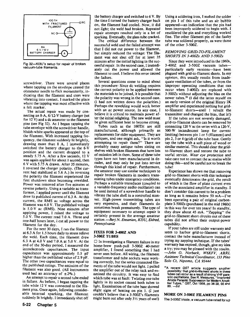
Fig 32-KI3U's setup for repair of brokenvacuum-tubs filaments.
screwdriver. There were several placeswhere tapping on the envelope caused theohmmeter needle to flick momentarily, indicating that the filament and stem werevibrating into contact. I marked the placewhere the tapping was most effective witha felt marker.
The actual repair was made by connecting an B-A, 6/12-V battery charger (setfor 12 V) and a de ammeter to the filamentpins (see Fig 32). As I began tapping thetube envelope with the screwdriver handle,bluish-white sparks appeared at the top ofthe filament. With increased tapping frequency, the filament suddenly lit brightly,drawing more than 8 A. I immediatelyswitched the battery charger to the 6-Vposition and the current dropped to asteady 5.75 A. After a few seconds, 12 Vwas again applied for about 1 second, then6 V with 5.75 A drawn. After 35 minutes,I reversed the charger polarity. (The current had stabilized at 5.6 A.) In reversingthe polarity the filament experienced thefirst shutdown since becoming rewelded.Power was removed after five minutes atreverse polarity. Using a variable ac transformer, I applied power until the filamentdrew its published current of 6.3 A. At thiscurrent, the RMS ac voltage across thefilament was 4.0 V. The published voltageis 5.0-V ac (RMS). Nine minutes afterapplying power, I raised the voltage to5.0 V. The current read 7.0 A. Three andone-half hours later, I cut all power to thefilament for the day.
For the next 30 days, I ran the filamentat 6.3 A for 1.5 hours daily to stress relievethe weld. Each time, the filament drew6.3 A at 4.0 V and 7.0 A at 5.0 V. At theend of the 30-day period, I measured theinterelectrode capacitances. The inputcapacitance was approximately 0.5 pFhigher than the published value of 2.9 pF.The other two capacitances were equal tothe published ratings. The emission of thefilament was also good. (All instrumentsused had an accuracy of ±2%.)
An attempt to repair a second tube endedin failure. As before, I began tapping thetube while 12 V was connected to the filament pins. Once again, following considerable internal sparking, the filamentsuddenly lit brightly. I immediately shut off
5-22 Chapter 5
100THWITH FRACTURED
FILAMENT
NC
SA6 V 112V
8ATTERY CHARGER
,---oNC
the battery charger and switched to 6 V. Bythe time I turned the battery charger backon, the filament had cooled. Now, it didnot light; the weld had broken. Repeatedrepair attempts resulted only in a lot ofsparking. Eventually, the glass tube cracked.
The critical difference between thesuccessful weld and the failed attempt wasthat I did not cut power to the filament,but simply reduced the voltage: The filament was not shut off for at least 35minutes after the initial lighting in the successful repair. In the second case, I immediately cut the power and allowed thefilament to cool. I believe this error causedthe failure.
Several questions come to mind aboutthis procedure: Since de welding requiresthe correct polarity to be applied betweenthe materials to be joined, it is possible thatthe polarity was wrong in the second case.(I had not written down the polarities.)Perhaps the rewelding would work betterwith an ac power source. In any case, Ibelieve it is critical to maintain power after the initial relighting. The new weld mustbe given sufficient heat to become strong.
Tubes such as the lOOTH are stillmanufactured, although primarily asreplacements for older equipment. They areantiques, and one might ask, "Is it worthattempting to repair them?" There areprobably many antique tubes sitting onshelveswith broken filaments that have lotsof emission left in them. Some of these tubetypes have not been manufactured in decades, and may only be put into servicethrough this kind of repair. Furthermore,the amateur may use similar techniques torepair broken filaments in modern transmitting tubes under emergency conditions.Perhaps a suitable transducer (coupled toa variable-frequency audio oscillator) canbe used instead of a screwdriver handle tovibrate the tube shell in a controlled manner. High-power transmitting tubes arevery expensive, and their filaments dosometimes break prematurely. The type ofequipment necessary to attempt repair iscertainly present. in the average amateurstation.-Berj N. Ensanian, K/3U, Eldred.Pennsylvania
FIXES FOR 3-400Z AND3-500Z TUBES
o In investigating a filament failure in myhome-brew push-pull 3-5OOZ 40-meteramplifier, I found something that I hadnever seen before. All wiring, the filamenttransformer and tube sockets were working correctly, but the series connected filaments of the tube would not light. I pulledthe amplifier out of the relay rack and examined the circuitry. It was easy to findwhich tube was at fault: Twisting one tubelightly in its socket caused both tubes tolight. Examination of the tube base showedslight signs of heating on pin 1. (I justcouldn't believe that a 3-500Z's filamentsmight bum out after only 3 Y2 years of use!)
Using a soldering iron, I melted the solderon pin I of this tube and an air bubbleappeared-an indication that the pin hadbeen improperly soldered to begin with. Iresoldered the pin and everything workedfine. The other filament pin of the faultytube was soldered properly, as were thoseof the other 3-500Z.
REMOVING GRID-TO-FILAMENTSHORTS IN s-sooz« AND 3-5OOZs
Since they were introduced in the 1960s,3-400Z and 3-500Z vacuum tubesparticularly early versions-have beenplagued with grid-to-filament shorts, In myopinion, this usually results from inadequate ventilation of the tubes, or from theimproper operating conditions that canoccur when 3-4oozs are replaced with3-5OOZs without adjusting the bias on thenewer tubes." (I did the latter myself onan early version of the original Henry 2Kamplifier and experienced nothing but gridto-filament shorts-until I rebuilt thetransmitter and changed the bias, that is!)
If the tubes are not severely damaged,grid-to-filament shorts can be removed byconnecting 120V ac (in series with a 120-V,500-W incandescent lamp for currentlimiting) between pin I or 5 (filament) andpin 2, 3 or 4 (grid) of the tube base. Gentlytap the tube with a soft piece of wood orsimilar material. This should clear the gridto-filament short and restore the tube touseful service. Wear eye protection andtake care not to contact the ac mains whiledoing this-and becareful not to break thetube!
Experience has shown me that removinggrid-to-filament shorts with this techniqueeventually deteriorates the grid, the resultof which is the flow of plate current evenwith the associated amplifier in standby. Idon't consider this current to be a problemas long as it remains below 50 rnA-I'vebeen operating a pair of original carbonplate 3-500Zs (purchased in the mid 1960s)in this way for over ten years! In standby,they draw about 45 rnA. "Zapping" thegrid-to-filament short circuits out of thesetubes did not affect their output-powercapability.
If your tubes are still under warranty andseem to harbor grid-to-filament shorts,contact the tube manufacturer instead oftrying my zapping technique. If the tubes'warranty has expired, though, give my ideaa try; you may be pleased with the results.-John O. Norback, W6KFV, ARRLAssistant Technical Coordinator, 133 PinoSolo ct. Nipomo. CA 93444
2°A recent OST article suggests anotherpossibility: that grid-to-filament shorts in thesetubes can occur as a result of strong VHF parasitic oscillations. See A. Measures, "ImprovedAnode Parasitic Suppressionfor ModernAmplifier Tubes," OST, Oct 1988, pp 36-38, 66 and89. -Ed.
MORE ON 3-500Z FILAMENT PINSThe 3-500Z triode, a vacuum tube rated for up

to 500 watts of anode dissipation, remainspopular in commercial and amateur-built RFpower amplifiers; the aoo-watt 3-4002 preceded it. John C. Norback, W6KFV, described"Fixes for 3-400Z and 3-500Z Tubes"-hintson how to clear filament-to-grid short circuitsand cure intermittent filament operation inthese tubes. Our next three correspondentshave more to say about the 3-500Z's filament.Hints and Kinks prefaces their remarks withthis caution: If your tube fails under warranty,use that warranty and contact the tubemanufacturer for advice before attempting tomodify or repair your tube.-Ed.
o The output power of my home-made3-500Z linear amplifier suddenly dropped.Inspection revealed that one of its 3-5OOZswas unlit. Further checks showed correctfilament voltage at the tube sockets. Ireplaced the tube but wondered why a fairlynew tube would develop an open filament.A close inspection of the tube pins uncovered the problem. During manufacture,the tube pins are force-fitted over tube-basewires. Apparently, in areas with highhumidity like ours, the contact between thepins can become lossy. One of the filamentpins was so loose I could turn it on itsunderlying wire! After much experimentation, I have found a way to restore the reliability of the tube-pin connections.
Wrap the 3-5OOZ in a towel or other softcloth. Lay the tube on a rug or towel placedon your workbench. With a high-wattagesoldering gun or iron, unsolder the bottomof the pins on the filament wires. (Attacha large heat sink to the wire between thepin and the tube base to avoid overheatingthe wire-to-glass seal.) Using a drill bit thatjust fits inside the tube pins, ream the inside of the pins until they're clean andbright. Resolder the pins carefully and wipethe newly soldered pins with solvent to remove remaining rosin. I have used thismethod on several intermittent-filamenttubes with good success.-Jim Brenner.NT4B, 5690 SW 36 A ve, Ocala, FL 32674
o Having had considerable experiencewith 3-500Z failure related to apparentfilament-pin-soldering failure, I ambeginning to wonder if the real problemis how the wires are soldered into thepins. Because I had very carefully cleanedand resoldered the intermittent filamentpins with each repair, I looked more carefully at the problem the last time itoccurred.
The first thing I noticed was that theaffected filament pin was very hot. (I hadremoved the tube immediately after itfailed.) In fact, it was so hot that solder hadmelted and run out of the pin! Althoughit is possible that a poor solder connectionin the pin could have caused resistanceheating, I am quite sure that the pin waswell soldered because I hadcarefully resoldered it myself.
I suspect that the real culprit is poorspring tension in the socket contact. whichleads to poor contact between the socketcontact and pin, and hence to resistanceheating of the contact and pin. Putting thisthinking into practice, I replaced the socketinvolved (it had been somewhat damagedby the heat anyway) and tightened thespring part of the contacts on my amplifier's other 3-500Z socket.
To date (about six months later), I havehad no further problems. The amplifier. bythe way, is a Heathkit SB-220.-WayneMills, N7NG, Box 1945, Jackson, WY83001o I don't believe that manufacturers buildthese tubes with bad filament-pin solderconnections. The problem is created byloose tube sockets. Loose pins in the socketcause high-resistance filament-pin-to-socketconnections, further causing the pins toheat up and the solder to drop down in thepin and cause an open circuit.
Cure: On my Drake L75 amplifier, I installed a new tube socket and, using ajeweler's torch, resoldered the pins with EZFlow silver solder. End of problem. Beforereplacing the socket, I had the same 3-500Zfail twice.-Pau/ "Van" Van Bolhuis,W4ZBD, R 4-Box 17D Pumphouse Rd,Westminster, SC 29693
2C39 HEATER CONNECTIONS FROMSO-239 CENTER PINSo Searching for a means of making a connection to the female heater terminal on a2C39/7289 tube, I found that the centercollet of an SO-239 coaxial jack fit the billnicely. (Secure the 80-239 in a vise, soldercup up. Several sharp hammer blows to thesolder cup will drive the collet out of the80-239 center insulator.) If better contactis needed between the 50-239's femaleheater terminal, the slit end of the collet canbe flared slightly by careful bending.-Harry Conowal, WA40FS, 2007Peachtree Blvd, St Cloud, FL 32769
PLATE-CAP CONNECTORS
o Heat-sink plate caps are nice to have,but some of us that build amplifiers don'trun 3 kW. If you have gone into anelectronics supply house lately and askedfor a plate cap, you probably got puzzledlooks and a profusion of dusty boxes flyingout of a back room.
A suitable cap can be made from ablock-style fuse holder. Do so by drillingout the rivet that holds the fuse clip to theplastic block, then use a hammer to formthe clip completely around a metal rodhaving the same diameter as the plate cap.The rivet hole fits a no. 4-40 screw for coonections.-Karl Kauffman, N/6H. MorganHill, California
KNIFE-SWITCH RESISTANCE FIX
o If you're using a knife switch in yourstation-I useone at RF-check the resistancebetween the blade and its pivot. Erratic switchperformance puzzled me until I checked theresistance of my switch: 4 ohms! A flexiblejumper (braid is suitable) from blade to pivotsolved this problem.-Jack Nelson, W2FW,Schenectady, NY
QUICK REPLACEMENT FORMULTIPIN CONNECTORS
o After I bought a Collins R-392 receiverat a summer swap meet, I discovered thatI couldn't test it because I didn't have amate for its power connector. Here's onesolution to this problem. Obtain a packageof solder less butt-splice connectors (wiresize no. 22-18 in this example). Count outone for each of the pins you wish to accesson the equipment plug. Crimp one end ofeach of the solderless connectors justenough for a snug, sliding fit on theequipment-plug pins. "Hard crimp" connecting wires to the other ends of thesolderless connectors, and slide the connectors onto the appropriate pins of theequipment plug. (If you use uninsulatedbutt splices, slip a short piece of insulatingtubing over each splice to avoid shortcircuits between the equipment pins.) I havesuccessfully used this method to furnishspeaker, mic and power connections toseveral pieces of equipment.-KenKolthoff, K8AXH/6, Vandenberg AFB,California
Construction 5-23

II
I
I
I
I
I
I
II
I
I
I
I
II
I
II
I
I
II
I
I
I
II
II
I
I
I
I
I
I
I
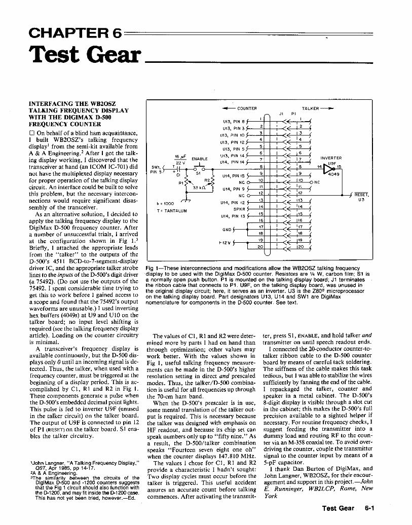
CHAPTER 6===========:======
TestGear
ter, press SI, ENABLE, and hold talker andtransmitter on until speech readout ends.
I connected the 2o-conductor counter-totalker ribbon cable to the D-500 counterboard by means of careful tack soldering.The stiffness of the cable makes this tasktedious, but I was able to stabilize the wiressufficiently by fanning the end of the cable.I repackaged the talker, counter andspeaker in a metal cabinet. The D-500's8-digit display is visible through a slot cutin the cabinet; this makes the D-500's fullprecision available to a sighted helper ifnecessary. For routine frequency checks, Isuggest feeding the transmitter into adummy load and routing RF to the counter via an M-358 coaxial tee. To avoid overdriving the counter, couple the transmittersignal to the counter input by means of a5-pF capacitor.
I thank Dan Burton of DigiMax, andJohn Langner, WB20SZ, for their encouragement and support in this project.-JohnE. Runninger, WB2LCP, Rome, NewYork
~
U13, PIN ~ ~
,(
,f,
2 ,( I 2 iU13, PIN 3
Ut3, PIN 10 s ( I' f• ,(
I. iU13, PIN 12 IU13, PIN 5
5 ( ,5 fUt3, PIN 14
6 ,( ,6 f#F ENABLE ,
17 INVERTERUt4, PIN t4
7/( i2V -L '. 1~~,
e ,9
,/( ,9 i,
Ut4, PIN 15 4049
R2 NC 10 ( Ito o NCR1 " .--.33 k!l. U14, PIN 9 I ",
( '" f12
112
NCrl-,
U14, PIN 12 ~\3 ( ,\3 f,. ,
( '" fLUM SPKRI
,U14, PIN 13 I
15 ( I t5 f'6 ( 1t6 fI 17 I
( "7 fGNOI 'iBta ( 5,
19 ,( 1
19 f+12VI
,20 ( 120 f
The values of CI, Rt and R2 were determined more by parts I had on hand thanthrough optimization; other values maywork better. With the values shown inFig 1, useful talking frequency measurements can be made in the D-500's higherresolution. setting in direct and prescaledmodes. Thus, the talker/D-500 combination is useful for all frequencies up throughthe 70-cm ham band.
When the D-500's prescaler is in use,some mental translation of the talker output is required. This is necessary becausethe talker was designed with emphasis onHF readout, and because its chip set canspeak numbers only up to "fifty nine." Asa result, the Dw500/talker combinationspeaks "Fourteen seven eight one oh"when the counter displays 147.810 MHz.
The values I chose for Ct , RI and R2provide a characteristic I hadn't sought:Two display cycles must occur before thetalker is triggered. This useful accidentassures an accurate count before talkingcommences. After activating the transmit-
k =1000
T = TANTA
......-- COUNTER TALKER __
JI PI
'62
SWI ( TJPIN5~
C
Fig 1-These interconnections and modifications allow the WB20SZ talking frequencydisplay to be used with the OigiMax 0-500 counter. Resistors are 1f4 W, carbon film; S1 isa normally open push button. P1 is mounted on the talking display board; J1 terminatesthe ribbon cable that connects to P1. U9F, on the talking display board, was unused inthe original display circuit; here, it serves as an inverter. U3 is the zane microprocessoron the talking display board. Part designators U13, U14 and SW1 are OigiMaxnomenclature for components in the 0-500 counter. See text.
1John Langner, "A Talking Frequency Display,"OST. Apr 1985. pp 14-17.
2A & A Engineering.erhe similarity between the circuits of the
DigiMax D·500 and ·1200 counters suggeststhat the Fig 1 circuit should also function withthe D·1200, and may fit inside the 0·1200 case.This has not yet been tried, however.-Ed.
INTERFACING THE WB20SZTALKING FREQUENCY DISPLAYWITH THE D1GIMAX D·500FREQUENCY COUNTER
o On behalf of a blind ham acquaintance,1 built WB20SZ's talking frequencydisplay! from the semi-kit available fromA & A Engineering.' After I got the talking display working, I discovered that thetransceiver at hand (an ICOM IC-701) didnot have the multiplexed display necessaryfor proper operation of the talking displaycircuit. An interface could be built to solvethis problem, but the necessary interconnections would require significant disassembly of the transceiver.
As an alternative solution, I decided toapply the talking frequency display to theDigiMax D-500 frequency counter. Aftera number of unsuccessful trials, I arrivedat the configuration shown in Fig 1.3
Briefly, I attached the appropriate leadsfrom the "talker" to the outputs of theD-500's 451I BCD-to-7-segment-displaydriver IC, and the appropriate talker strobelines to the inputs of the D-500's digit driver(a 75492). (Do nol use the outputs of the75492. I spent considerable time trying toget this to work before I gained access toa scope and found that the 75492's outputwaveforms are unusable.) I used invertinghex buffers (4049s) at U9 and UIO on thetalker board; no input level shifting isrequired (see the talking frequency displayarticle). Loading on the counter circuitryis minimal.
A transceiver's frequency display isavailable continuously, but the D-500 displays only 0 until an incoming signal is detected. Thus, the talker, when used with afrequency counter, must be triggered at thebeginning of a display period. This is accomplished by C I, R1 and R2 in Fig I.These components generate a pulse whenthe D-500's embedded decimal point lights.This pulse is fed to inverter U9F (unusedin the talker circuit) on the talker board.The output of U9F is connected to pin 12of PI (RESET) on the talker board. S! enables the talker circuitry.
Test Gear 6·1
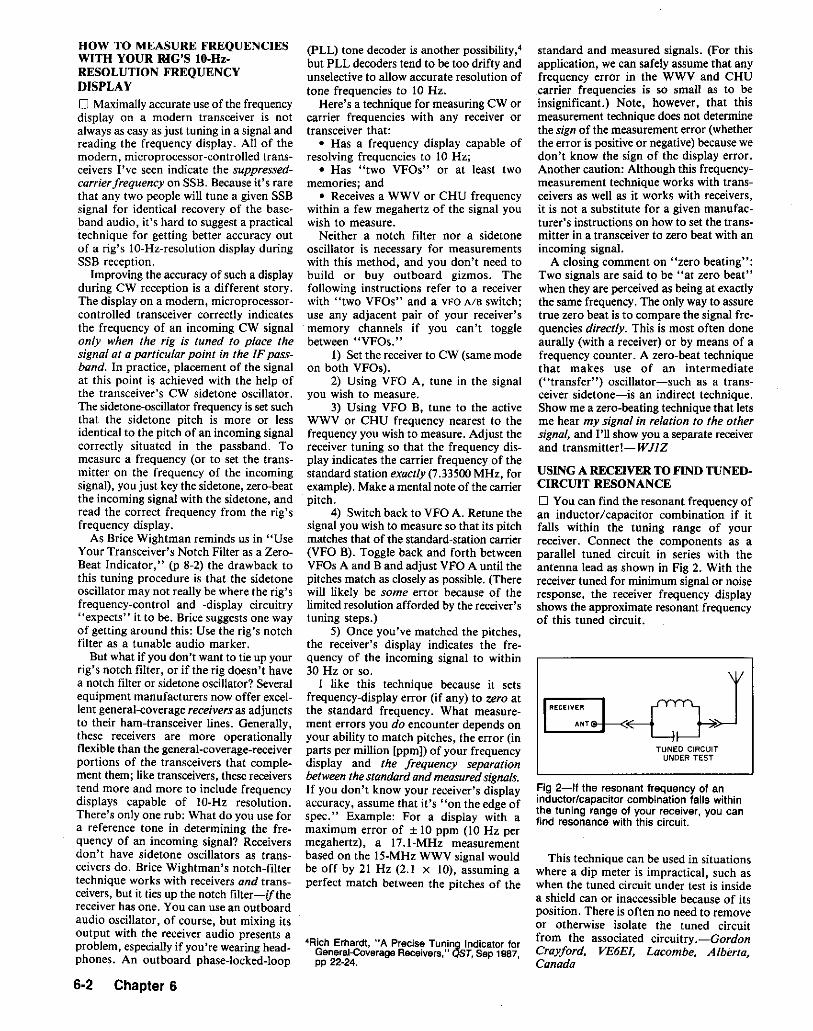
HOW TO MEASURE FREQUENCIESWITH YOUR RIG'S 10-HzRESOLUTION FREQUENCYDISPLAY
o Maximally accurate use of the frequencydisplay on a modern transceiver is notalways as easy as just tuning in a signal andreading the frequency display. All of themodern, microprocessor-controlled transceivers I've seen indicate the suppressedcarrier frequency on SSB. Because it's rarethat any two people will tune a given SSBsignal for identical recovery of the baseband audio, it's hard to suggest a practicaltechnique for getting better accuracy outof a rig's lO-Hz-resolution display duringSSB reception.
Improving the accuracy of such a displayduring CW reception is a different story.The display on a modern, microprocessorcontrolled transceiver correctly indicatesthe frequency of an incoming CW signalonly when the rig is tuned to place thesignal at a particular point in the IF passband. In practice, placement of the signalat this point is achieved with the help ofthe transceiver's CW sidetone oscillator.The sidetone-oscillator frequency is set suchthat the sidetone pitch is more or lessidentical to the pitch of an incoming signalcorrectly situated in the passband. Tomeasure a frequency (or to set the transmitter on the frequency of the incomingsignal), you just key the sidetone, zero-beatthe incoming signal with the sidetone, andread the correct frequency from the rig'sfrequency display.
As Brice Wightman reminds us in "UseYour Transceiver's Notch Filter as a ZeroBeat Indicator," (p 8-2) the drawback tothis tuning procedure is that the sidetoneoscillator may not really be where the rig'sfrequency-control and -display circuitry"expects" it to be. Brice suggests one wayof getting around this: Use the rig's notchfilter as a tunable audio marker.
But what if you don't want to tie up yourrig's notch filter, or if the rig doesn't havea notch filter or sidetone oscillator? Severalequipment manufacturers now offer excellent general-coverage receiversas adjunctsto their ham-transceiver lines. Generally,these receivers are more operationallyflexible than the general-coverage-receiverportions of the transceivers that complement them; like transceivers, these receiverstend more and more to include frequencydisplays capable of lO-Hz resolution.There's only one rub: What do you use fora reference tone in determining the frequency of an incoming signal? Receiversdon't have sidetone oscillators as transceivers do. Brice Wightman's notch-filtertechnique works with receivers and transceivers, but it ties up the notch filter-if thereceiver has one. You can use an outboardaudio oscillator, of course, but mixing itsoutput with the receiver audio presents aproblem, especially if you're wearing headphones. An outboard phase-locked-loop
6-2 Chapter 6
(PLL) tone decoder is another possibility,"but PLL decoders tend to be too drifty andunselective to allow accurate resolution oftone frequencies to 10 Hz.
Here's a technique for measuring CW orcarrier frequencies with any receiver ortransceiver that:
• Has a frequency display capable ofresolving frequencies to 10 Hz;
• Has "two VFOs" or at least twomemories; and
• Receives a WWV or CHU frequencywithin a few megahertz of the signal youwish to measure.
Neither a notch filter nor a sidetoneoscillator is necessary for measurementswith this method, and you don't need tobuild or buy outboard gizmos. Thefollowing instructions refer to a receiverwith "two VFOs" and a VFO AlB switch;use any adjacent pair of your receiver'smemory channels if you can't togglebetween "VFOs."
1) Set the receiver to CW (same modeon hath VFOs).
2) Using VFO A, tune in the signalyou wish to measure.
3) Using VFO B, tune to the activeWWV or CHU frequency nearest' to thefrequency you wish to measure. Adjust thereceiver tuning so that the frequency display indicates the carrier frequency of thestandard station exactly (7.33500 MHz, forexample). Make a mental note of the carrierpitch.
4) Switch back to VFO A. Retune thesignal you wish to measure so that its pitchmatches that of the standard-station carrier(VFO B). Toggle back and forth betweenVFOs A and B and adjust VFO A until thepitches match as closely as possible. (Therewill likely be some error because of thelimited resolution afforded by the receiver'stuning steps.)
5) Once you've matched the pitches,the receiver's display indicates the frequency of the incoming signal to within30 Hz or so.
I like this technique because it setsfrequency-display error (if any) to zero atthe standard frequency. What measurement errors you do encounter depends onyour ability to match pitches, the error (inparts per million [ppm]) of your frequencydisplay and the frequency separationbetween the standard and measuredsignals.If you don't know your receiver's displayaccuracy, assume that it's "on the edge ofspec." Example: For a display with amaximum error of ± 10 ppm (10 Hz permegahertz), a 17.1-MHz measurementbased on the IS-MHz WWV signal wouldbe off by 21 Hz (2.1 x 10), assuming aperfect match between the pitches of the
4Rich Erhardt, "A Precise Tuning Indicator forGeneral-Coverage Receivers," QST, Sep 1987,pp 22·24.
standard and measured signals. (For thisapplication, we can safely assume that anyfrequency error in the WWV and CHUcarrier frequencies is so small as to beinsignificant.) Note, however, that thismeasurement technique does not determinethe sign of the measurement error (whetherthe error is positive or negative) because wedon't know the sign of the display error.Another caution: Although this frequencymeasurement technique works with transceivers as well as it works with receivers,it is not a substitute for a given manufacturer's instructions on how to set the transmitter in a transceiver to zero beat with anincoming signal.
A closing comment on "zero beating":Two signals are said to be "at zero beat"when they are perceived as being at exactlythe same frequency. The only way to assuretrue zero beat is to compare the signal frequencies directly. This is most often doneaurally (with a receiver) or hy means of afrequency counter. A zero-beat techniquethat makes use of an intermediate("transfer") oscillator-such as a transceiver sidetone-is an indirect technique.Show me a zero-beating technique that letsme hear my signal in relation to the othersignal, and I'll show you a separate receiverand transmitter!-WJ1Z
USING A RECEIVER TO FIND TUNEDCIRCUIT RESONANCE
o You can find the resonant frequency ofan inductor/capacitor combination if itfalls within the tuning range of yourreceiver. Connect the components as aparallel tuned circuit in series with theantenna lead as shown in Fig 2. With thereceiver tuned for minimum signal or noiseresponse, the receiver frequency displayshows the approximate resonant frequencyof this tuned circuit.
II RECEIVER
II ANT
TUNED CIRCUITUNDER TEST
Fig 2-lf the resonant frequency of aninductor/capacitor combination falls withinthe tuning range of your receiver, you canfind resonance with this circuit.
This technique can be used in situationswhere a dip meter is impractical, such aswhen the tuned circuit under test is insidea shield can or inaccessible because of itsposition. There is often no need to removeor otherwise isolate the tuned circuitfrom the associated circuitry.-GordonCrayford, VE6EI, Lacombe, A Iberia,Canada

(Eq I)
RX
M"" 1,000,000
Fig 3-Cornelio Nouel measures resistances above the highest range on his DMMwith the help of this circuit and Table 1.
that correspond to selected values of Rxfor Rs = 2 MO. (Any reasonable valuecan be used for Rs; I settled on 2 Milbecause that value fit the components I hadon hand.) Using a pocket calculator,resistance values up to 50 MO can be determined with reasonable accuracy.CornelioNouel, KG5B, 4966PaseodelReyDr, Brownsville, TX 78521
capacitor leads (don't cut the leads short).The measurement procedure is as
follows: Find the total inductance .of thetest clips, the capacitor leads and thecapacitor itself. Do this by shorting the testclips together and measuring the textfixture's self-resonant frequency (alwayssomewhere at VHF) with the dip meter.(Couple the dip meter to the loopcomprising the capacitor, leads and testclips for this test.) Because you know thevalue of the capacitor, you can find thetotal L by using the formula
L = I + 4..2f2C (Eq 2)
whereL = inductance in henrysf = frequency in hertzC = capacitance in farads
With the 47-pF capacitor I used in mytest fixture, the total L worked out to be0.086 JLH. I wrote this inductance on apaper label and fastened it to the test fixturefor future reference.
To measure the inductance of a low-Linductor l clip the test fixture across theends of the inductor and measure the new,lower resonant frequency with a dip meter.Then, find the total inductance of theunknown inductor and the test fixture withEq 2. Since you already know theinductance contributed by the test fixture(0.086 JLH in my case), you can find theunknown L by subtraction.-Richard L.Measures, AG6K, 6455 La Cumbre Rd,Somis, CA 93066
SAlfReinertsen, "The L-Meler," QST, Jan 1981,pp 28-29.
6Doyle Strandlund, "Amateur Measurement ofR+jX," QST, Jun 1965. PP 24-27.
STRAY CAPACITANCE AFFECTSINDUCTANCE MEASUREMENTS
o As I calibrated my version of theL-Meter, 5 measurement errors confusedme until I realized what was happening.Although a coil of wire exhibits inductance,there is also distributed capacitancebetween the turns of the coil. Because theL-Meter (an oscillator) depends on tunedcircuit resonance to measure inductance,the inductance and distributed capacitanceof the inductor under test are factors in itsinductance measurements.
When an inductor is measured on areactance bridge or Doyle Strandlund l sgadget.f the inductor's capacitivereactance cancels part of its inductive reactance. This results in an inductance readingless than the actual inductance of theinductance under test. Distributedcapacitance has the opposite effect inmeasurements made with the oscillatingL-meter: The measured inductance of thecomponent under test appears to be greaterthan the actual inductance of thepart.-Herbert T. Bates, KADCAG, 1622Fairview A ve, Manhattan, KS 66502
Rx,MIl
9.010.015.020.030.040.050.0
Reading,MIl1.6361.8681.7651.8181.8751.9051.923
DigitalMultimeter
OHMS
~~MnRS AOJ
vvv v v v"'-' NC, Mn
I ,,RS
MEASURING THE INDUCTANCE OFLOW-L INDUCTORS
o In "Calculating Power Dissipation inParasitic-Suppressor Resistors" (QST, Mar1989, pp 25-2S), I stated that the amountof inductance used in a parasitic suppressorhas a large effect on the HF power dissipated in the resistor. Because thesuppressor-resistor power dissipation cannot be calculated without knowing the inductance of the suppressor inductor, amethod of accurately measuring values ofsmall inductance is useful. Here's how I dothis without'exotic test equipment.
The items required are a dip meter, adisc-ceramic fixed capacitor (with 1Y2- to2-inch-long leads) of a known valuebetween 30 and 62 pF, and two miniaturecopper test clips. Construct a test fixtureby soldering the miniature test clips to the
Table 1DMM Readings for Rx Valuas withR.=2MIIReading, Rx,MIl MIl,.,,1 2.51.200 3.01.273 3.51.333 4.01.428 5.01.500 6.01.555 7.01.600 8.0
USING A RECEIVER AS ANEUTRALIZATION INDICATOR
o Ham lore has it that grounded-gridamplifiers need not be neutralized. but thisis true only at frequencies at whichreactances in the tube(s) and amplifiercircuitry do not encourage positive feedback. I was reminded of this when I builta grounded-grid amplifier using parts Ialready had on hand. The tubes Iused-S05s-work weII as class-B audioamplifiers but were not designed forgrounded-grid RF service. This groundedgrid amplifier required neutralization! Myneutralizing technique requires only areceiver(or transceiver in receivemode) andan antenna.
First, remove all power from theamplifier and be sure its high-voltage filtercapacitors are safely discharged. Next,hardwire the RF contacts of the amplifierTR relay into the transmit mode. Connectthe receiver to the amplifier input and theantenna to the amplifier output. Tune ina steady signal and peak the amplifier tankcircuit for a maximum S-meter reading.Adjust the amplifier neutralizing capacitorfor a signal null. Finally, return the TRrelay wiring to normal. The amplifier isneutralized.
I like this technique because it can bedone when nothing in the amplifier is hot,thermally and electricalIy.-Scotl Reaser,K6TAR, Pacific Palisades, CaliforniaEditor's Note: Although neutralization of theamplifier went well, K6TAR later reported that therig didn't pan out. Showing true ham spirit, Scottpenned this note on the back of his publicationrelease form: "Please note that although I thinkthe idea I submitted has merit, that particularapplication was a disaster. Case in point: 805tnodes made a lousy linear, even if the tubes werefreel Subsequent to my original communication,I started over with the amplifier. Rebuilt with asingle 3-5OOZ and a Hypersill!l transformersupply,the amplifier works nicely. The lesson is to useparts designed for the application."
EXTEND THE RESISTANCEMEASUREMENT RANGE OF A DMM
o My digital muItimeter (DMM) measuresresistance up to 2 megohms, and this isadequate in most cases. When I need tomeasure resistances higher than 2 MO, I usethe circuit shown in Fig 3. When two resistors are connected in parallel, the resultantresistance is always lower than the value ofthe lower resistor. The unknown resistancecan be found from the formula:
R_RsXRTx - Rs R
T
where Rx is the unknown resistance, Rs isthe standard resistance (2 MO in this case)and RT is the value indicated by theDMM.
As Fig 3 shows, my Rs consists of a1.2-MO fixed resistor in series with a I-MOpotentiometer (wired as a rheostat); I adjustthe pot so that Rs = 2 MO. Next, Iconnect Rx to the circuit and read RT onthe DMM. Then I solve for Rx with Eq I.Table 1 shows the DMM (RT) readings
Test Gear 6-3

18kO te en
Fig 5-Daniel Swenson and RobertJensen add an emitter-follower buffer(02) to The ARRL Handbook's bridged-Taudio oscillator (Q1) to provideaudio output at a low impedance(=65 0). By itseif, the Handbook osciliator works well only when driving high
impedances-l00 kOor more. With thecomponent valuesshown, Q1 oscillatesat ..,750 Hz. The9-V battery's snapon connector servesas a power switch.
drain and connecting the drain lead to pin7 of the 555, although I haven't triedthis.-Dale Hunt, WB6BYU, 1612 WCherry A ve, Lompoc, CA 93436
A BUFFER FOR THE HANDBOOKBRIDGED-T OSCILLATOR
o The one-transistor audio oscillatorpictured on page 25-20 of the 1991 ARRLHandbook for Radio Amateurs requires a
Fig 4-The pitch of Dale Hunt's voltagecontrolled oscillator rises with increasing acsignal amplitude at the INPUT terminal.
k= 1.000
1MO
9V-~ TI~ER
555+
4 8
10 RESET Vee
kO10 ~F
7FREQ ADJ DISCH 16V
31 M 0 OUT + t---------o OUTPUT
10 ~F 2 ""018 V
8 e"" 511<.eND V
0.002 0.01
MPF102 J:' ;L~'lN34A G
lN34A 0.01
J/'INPUT o----lt-~--+"''''''-~
0.01~,
R15.1 kO
A VOLTAGE-VARIABLE AUDIOOSCILLATOR
o Fig 4 shows the circuit for a simplevoltage-variable oscillator based on theubiquitous 555 timer. Its oscillation frequency can be varied over several octaves.
I designed the circuit as an audio detector for an impedance bridge, so I couldwatch what I was adjusting instead of ameter. The oscillator pitch is lowest withno ac voltage applied to INPUT, and risesas the input-signal level increases. The opposite characteristic-highest pitch with noinput signal-can be obtained by eliminating the 1O-~F capacitor at the MPFlO2
IMPROVISING A CALIBRATEDAUDIO GENERATOR
o Have you ever wished you had an audiosignal generator? You may already haveone that's accurate and stable, and whoseoutput is smoothly controllable, in yourMF/HF transceiver! If your transceiver
, contains a marker generator and a digitalfrequency display, you can probably use itto generate audio signals at known pitches.Here's how.
Tune the transceiver to exact frequencyof one of its marker signals-such as28,300.00 kHz (28.30000 MHz).' Turn onits marker generator and set its MODE
switch to lower sideband (LSB). If thetransceiver allows adjustment of its IFbandwidth during LSB reception, set its IFbandwidth to maximum. Tune upward infrequency-slowly. When the frequencydisplay reads 28.300.05 or so, you maystart to hear a low-pitched audio tone; at28.300.05, this is an audio pitch of 50 Hz'You can use the radio's RIT control forfine tuning, if desired.
By reading the digital readout andmentally subtracting the starting frequency (28.300.00 in this case) from it, you candetermine the frequency of the markersignal pitch. If your starting frequency was28.300.00 MHz and your display now indicates 28.301.20, the pitch you'rehearing-assuming that the frequency display is accurate, and that the marker signalis actually at 28.30000 MHz-is 1.2 kHz.If your transceiver includes IF-shift and/orIf-slope-tuning controls that operate inLSB, adjust these controls to maximize themarker-signal level (as indicated on thetransceiver S meter) as you tune.
The maximum audio frequency you maybe able to develop may be 2.7 to 3.0 kHz,depending on your transceiver's IF bandwidth, the frequency differential betweenthe transceiver's BFO and IF center, andthe range of its IF-shift and IF-slope-tuningcontrols. Because the audio frequenciesused for routine Amateur Radio voice anddigital communications are quite a bitlower than those necessary for hi-fi, thisfrequency-generation limit is not a disadvantage because it allows us to generatethe highest audio frequencies we can usein our rigs on SSB.-Martin L. Cardwell,NB3T, 4600 White A ve, Baltimore, MD21206
1Most current transceivers display medium frequencies (300 kHz to 3 MHz) and high frequencies (3 to 30 MHz)with two decimal points-onebetween the l-MHz and lOa-kHz places, andanother between the l-kHz and O.l-kHz places.For the frequency given, such a display reads28.300.00 for 28.30000 MHz (28,300,00 kHz).-AK7M
8Adjusting the radio's IFSHIFT control to producelower-pitched backgroundnoisemay helpsomewhat; on the other hand, 50 Hz may be a bit toolow for some transceiver audio systems toreproduce anyway. If so, keep tunrng; you'llprobably hear the signal between28.300.10 and28.300.20.-AK7M
~0.05~F
0.02 ~F 0.02 ~F
~"
0.05 ~f R3
82 kO
100 en >---l!--....-+-fLEVEL
R21 kO
Q22N3904
0.5 ~F
f:----? Probe
...-----1 Ground
6-4 Chapter 6

os
DEVICEUNDERTEST
Ie)
GROUND
(8)
HOT
LIMIT OFF
LIMIT ON
MOMENTARYLIMIT OFF
CONNECT SCOPE PROBEGROUND LEADS TO
(A) GROUND OF CIRCUITUNDER TEST
Y INPUT
Fig 7-Using the horizontal (x-exts) andvertical (V-axis) inputs of a single-traceoscilloscope as a dual-channel logic probe.Connect the X and Y inputs as shown at A.B shows the display when the inverterinput is high, and C shows the displaywhen the inverter input is low. Scopesensitivity is 5 V/div in these examples.
INVERTER
X INPUT
lamp-say, 40W or less-and working up in lampwattage until even a high-wattage lamp-200 Wor so-is not lit to full brilliancebythe currentdrainof the device under test.)
You can also use a light-bulb current limiter toreduce the heat of a soldering iron. Plug the ironinto J and try lamps of differentwattagesuntil theiron's temperature is where you want it.-AK7M
P-120 V ac cord set with plug.S1-SPST toggle rated 3 A (or more) at
120 V ac.52-SPOT on, center-off, momentary-on
toggle rated 3 A (or more) at 120 V ac,
,,,,L_-O GROUND '* *
,,'*rh
51
ONPOWER
~ IF METAL ENCLOSURE USED
** SEE CAPTION
F
GROUND
(GREEN)
HOT
NEUTRAL NEUTRAL
(WHITE)
(BLACK) 3A
p
120 VAC
Properly applied, this circuit can also be used asan aid to restoring vintage or long-unusedequipment-especially transformer-operatedequipmentthat has beenstoredunderhumidconditions. ("Firing up" such gear cold may literallyresult in fire because of moisture-induced shortcircuits in transformer windings.) Page 26-28ofthe 1988 ARRL Handbook discusses safeprocedures for burning in vintage gear with thehelp of a variable-voltageautotransformer. LewHoward's current limiter can serve as a cheapand-dirty substitute for a variable-voltagetransformer in this application if a suitable selectionof incandescent lamps is available. (The lower alamp's wattage, the higher its resistance. Usethelamp current limiter to power up vintage equipment in steps by starting with a low-wattage
When 81 is turned on, the brightness ofDS indicates the absence or presence of ashort-circuit fault in the device under test.If the lamp burns at full brilliance, a shortcircuit exists. If the lamp burns at partialbrilliance, the device under test is probablysound. S2 can be set to LIMIT OFF to apply120 V ac to the device under test if allappears well; pushing S2 to MOMENTARYLIMIT OFF does likewise as long as theswitch is kept in this position. Should thedevice under test fail with full mains voltage applied, the fuse, F, provides muchbetter protection than the 15-A fuses orbreakers that are standard in house wiring.
Of course, this device is nothing new andis certainly not an invention of mine. Afterlistening to many woebegone on-the-airdiscussions related to troubleshooting,though, I felt compelled to share this bitof knowledge-it may help save a lot offuses and expensive gear!-Lewis N.Howard, W4LHH, 4132 Creek Stone CI,Stone Mountain, GA 30083
Fig 6-Lew Howard's current limiter uses an incandescent lamp to prevent serious equipment damage should a short circuit occur in the device under test. If you build the currentlimiter into a metal enclosure, be sure to connect the mains ground wire (green) to theenclosure. It's also a good idea to add a GROUND binding post (connected to the mainsground wire) to the current limiter for use with equipment having two-wire ac cords. Thisallows the chassis of the device under test to be connected to the ac mains ground forsafety. Speaking of safety: Contact with the ac mains can kill you. Be careful when constructing and using this circuit.OS-100-W, tao-v incandescent lamp in
ceramic socket. Other wattages may beuseful; see text.
F-3-A, 250-V fuse in panel-mountedholder.
J-120 V ac jack.
A SIMPLE CURRENT LIMITER FOREQUIPMENT TESTING
o Many years ago, when I was installingand servicing electron microscopes as afield representative for RCA, one of themost important items in my tool kit was arubber pigtail socket equipped with alligator clips and a 100-W, 120-V lamp. Thisgadget was really useful for locating fuseblowing faults in power supplies andassociated equipment. Since then, I've gonea step further and added switches and afuse as shown in Fig 6. The result is a compact current-limiting unit that can be usedto check transformers and other equipmentfor short circuits.
The lOO-W lamp, DS, serves as a currentlimiting resistor. The device under test isplugged into J, and P is connected to a120 V ac source. S2, LIMIT, is a SPDT (on,center-off, momentary-on) toggle switch.With S2 set to LIMIT ON, DS is in serieswith the device under test across the ac line.Full line voltage appears at J only if thedevice under test draws no current. Themore current drawn by the device undertest, the lower the voltage at J when 82 isset to LIMIT ON.
high-impedance load. Because we sometimes need to inject audio into lowimpedance circuits, we sought to adaptthis circuit to drive a wide range of loadimpedances. Our solution: a one-transistor buffer amplifier with a low outputimpedance.
Fig 5 shows the circuit as applied to theHandbook audio oscillator. Both stagescan be built on a small piece of perf board.Our version isn't housed in a case. Mounting the battery on the board with a smallclip makes the entire unit hand-holdable.The injection probe consists of an insulatedpiece of stiff hookup wire. A clip lead connects the commons of the probe and the circuit under test.
Set up the circuit as follows: Experimentwith the values of R1 (the oscillator collector resistor, starting with 3.3 kO as theHandbook suggests) to find a resistancethat's high enough to prevent appreciabledistortion, yet small enough to still give astrong output signal. (We settled on 5.1 kIJfor our application.) Next, disconnect theoscillator from the 9-V supply by unsoldering one of Rl 's leads. Measure and notethe de voltage across the buffer-stage emitter resistor (R2). Experiment with different values for the buffer-stage base-resistor(R3) until you find a resistance that causesabout one-half of the power supply voltage(4.0-4.5 V for a 9-V supply) to appearacross R2. Reconnect Rl. This completesadjustment.
Our injector's audio output is adjustablefromOto 150mV. The buffer's output impedance is about 65 n. The circuit draws6 rnA at 9 V, so battery life should be sufficient for many hours of testing.-DanielC. Swenson and Robert Jensen, WA8ASV,Waseca, Minnesota
Test Gear 6-5

USE A SINGLE-TRACE OSCILLOSCOPE AS A DUAL·CHANNELLOGIC PROBEo A dual-beam or dual-trace oscilloscopeis nearly a necessity in serious digital troubleshooting, but what if you have only a singletrace scope on hand? For some applications,a single-trace scope can simulate dual-traceperformance without using adapters ormodifications.
Fig 7 shows how you can simultaneouslyuse the X and Y inputs of a single-tracescope to monitor the input and output ofa TTL inverter. First, shut off the scope'ssweep. (Reduce the display intensity so thatthe resultant stationary dot does not damagethe CRT's phosphor coating.) Connect thescope's X input to the inverter input, andthe Y input to the inverter output as shownin A. Set the X and Y amplifiers for equalsensitivity. Insets Band C of Fig 7 show thescope display for a functional inverter withinput high (B) and low (C). If the input tothe inverter is clocked, the displayed spotshifts rapidly between these two positions,resulting in a diagonal line. Need a triggeror third channel? Use your scope's beam intensity modulation (Z-axis) input. An inexpensive, single-trace oscilloscope can besurprisingly useful in digital troubleshootingwhen it is applied with imagination.-B. N. Ensanian, KI3U, Williamsport,Pennsylvania
TEST RF INSULATORS IN AMICROWAVE OVENo From time to time, situations arisewhere a piece of scrap plastic would makea convenient RF insulator. Some plastics,however, are very lossy at RF. Unless theapplication is critical, a simple test can provide reasonable assurance that the material is suitable for the job.
To perform the test, irradiate an ounceor two of the material in a microwave oven.(Protect the oven by including a cup ofwater with the sample as an RF load.)Operate the oven at high power for two tothree minutes, then remove the sample. Ifthe plastic has become warm, it is probablytoo lossy for use as an RF insulator. (Thewarmth is more apparent if you cool thesample in a freezer for about 15 minutesjust before the test.) Insulators tested in thisfashion have given me no problems atpower levels up to 1000 W at 50-100MHz.-E. R. Berg, KZ9Y, Rockford,Illinois
small piece of copper-clad board andcoated it with epoxy resin for permanentoutdoor use. To minimize the pickup offeed-line radiation, I mount the meterantenna horizontally when samplingenergy from my horizontal HF dipolesand vertically for use with my 2-metergroundplane antenna.-Albert E. Weller,WD8KBW, 1325 Cambridge Blvd, Columbus,OH 43212
BEWARE OF ERRONEOUS METERREADINGS IN RF FIELDSo Checking the voltage on the dc line tomy 2-meter mobile transceiver, I saw thereading (nominally 12 V) drop by nearly avolt when I keyed the transmitter.Convinced that this wasn't an accuraterepresentation of the supply voltage, Ibypassed my multimeter for RF-and themeter indicated the proper 12 V. Then Iremembered building a regulated powersupply that showed an amazing amount ofac voltage at its dc output-a fictitiousindication caused by a parasitic oscillationin the supply'S pass-transistor-regulator circuitry.
A multimeter can give strangely erroneous readings in the presence of an RF field,or when ultrasonic audio energy is presentin the de or low-audio circuit under test.This effect can be especially severe whenthe meter test leads pick up RF energy. Forinstance, when you measure the voltage ona 60-Hz line, RF pickup may cause anabsurdly high reading that has nothing todo with the actual line voltage. (If youexperience this, try selecting another,higher, voltage range. You may discoverthat the meter reading is independent of therange selected-a sure sign that RF is theculprit.) The RF may be from your transmitter, if you're testing audio or ac powercircuits while it's operating.
Modern multimeters include protectivediodes across the terminals of their metermovements. This arrangement can allowrectification even when the meter rectifieris disabled (as is the case when the meterselector switch is set to a de voltage orcurrent range). Indication of an abnormalvoltage change, such as (false) evidence ofpoor voltage regulation in a well-regulatedsupply, is one possible result of this. If themultimeter includes a protective solid-statecircuit breaker, "RF in the meter" maycause the breaker to false.
A bypass eapacitor-a component thatallows RF to pass while blocking dcacross the multimeter's test-lead terminalsis an almost certain cure for theseproblems. Try 0.01 ~F at HF, O.OOj ~F atVHF. 9 (Be sure that the working voltageof the capacitor you use is greater than thevoltage expected in the circuit under test.)Repositioning the multimeter test leads mayalso help where direct RF pickup is aproblem.-Charles P. Baker, W2KTF,2715 Wilson Ave, Bellmore, NY II7IO
The high-gain sensing circuitry in electronicallyregulated power supplies may also be ~F se~sl
tive, so if you measure unexp~ctedly we,lrd shiftsin regulated-supply output With transmitter, keying, your voltmeter may not be at fault. Trying ameter of differentdesign(or a passivevoltagefcurrent indicator, such as a lamp or LED, capableof indicating relative level shifts) can help youdetermine whether the fault lies in the instrumentor the circuit under test.-Ed.
vlhe value you use is not critical in most cases,but accurate audio measurements may requirethat you minimize the bypass capacitance,perhaps augmenting it with an RF choke orchokes between the bypass capacitor and themultimeter terminals, to avoid rolloff toward thehigh end of the audio range.
NOISE BRIDGE AUDIO LINKSD Last year, while contemplating a moveto a new house with a new antenna system,I decided to build my own 20- and 15-meterYagis. After running computer designprograms for the antennas and the gammamatching stubs, I sought a similarlyaccurate method of adjusting the matchingdevices-a method that would not requiremultiple trips up and down the tower tocheck the system SWR in the shack.
Part of my solution to this problem wasto use a noise bridge at the antenna. Usinga noise bridge at any other locationseparated from the unknown impedance bya length of feed line-requires that thelength of the feed line be known. (Feed-linelengths that are multiples of electricalY2 Aallow R and X to be read directly fromthe bridge dials with no additional calculations; other lengths require correction ofthe bridge readings according to theelectrical length of the line.)
The difficulty with locating the noisebridge at the antenna is that the stationreceiver has to be left in the shack. I solvedthis problem by having a helper transmitthe receiver audio from the shack to me onthe tower by means of hand-held VHFtransceivers. This is now standard practice
f-A--1
Fig a-Albert Weller's field-strengthmeter uses four components, a fewhanks of wire and a DMM to indicatethe relative intensity of a transmittedfield,
A=1 '02 tt.A' = Ak =1000
330 kit
toDMM
e330 kn
"string
A SIMPLE FIELD-STRENGTH METERFlFig 8 illustrates a field-strength meterthat can be used for antenna or matchingnetwork tuning. It consists of a short dipoleantenna, a detector and a digital multimeter(DMM). With A and A' equal to about 2feet, the field-strength meter provides adequate near-field sensitivity from 80 through2 meters. (This is the range over which I'vetried the circuit; the meter's actual rangemay be wider.)
I built my version of the detector on a6-6 Chapter 6

A --------- CJUMPER FOR !!iZA
Fig 10-Schematic of the balanced dummyload. Resistors are 2·W, 5010-tolerance,carbon-composition units.
A-B" 70na-c s aooriAC-B=52!l.
SIX 1200.11. RESISTORSIN PARALLEL
( ZOOJl.)
B
EIGHT esc n RESISTORSIN PARALLEL
(101\.)
wood to ensure that they'll be covered withoil when the assembly is inverted after completion (see Fig II).
When the resistors and rods have cooled,brush off any excess rosin. remove theassembly from the lumber scrap and installit on the container lid. Use nuts and washers on both sides of the lid. Fill thecontainer about 3,4 full of mineral or transformer oil and put on the lid. Adjust theoil level. if necessary, but don't overfill thecontainer-oil is messy!
To use the dummy load, place it on acardboard box to isolate it from groundedobjects. Connect the balun under test to theappropriate terminals; use a jumper (as ~n
Fig 9) to connect the load branches mparallel if you need a 52-ohm load. Applypower (we use about 20 W -briefly) andcheck the SWR at the frequencies ofinterest. Don't let the load overheat. Theload also works well to check unbalancedtransformers (for example, 52 to 70 ohms)as well.-Dan, N6BZA, and Marty,W6BDN, Levin, Menlo Park, California
Fig 11-Construction of the balanceddummy load. The resistors, spaced to aidcooling, are immersed in mine.ral ortransformer oil to increase their powerhandling capability.
Fig 9-This dummy 108;d ~an be ~se~ toprovide a balanced resistive termination of52 70 or 200 ohms. For a 52-ohm load,co~nect a jumper as shown; no jU"!1pe~ isrequired for a 70- or 200-ohm termination.The unit can be used as an unbalancedload by grounding one of its terminals.
A BALANCED 52, 70 OR 200-0HMDUMMY LOADo If you want to check SWR with a balunin your antenna system, it's handy to havea balanced resistive termination of the correct impedance. Fig 9 shows an inexpensive, easy-to-build balanced dum~y loadthat exhibits commonly needed resistancesof 52 70 and 200 ohms. It will dissipateabout 40 W for short periods; this ratingis usually adequate for SWR checks.
The load consists of two resistorbranches, each of which is made of 2-W,5Olo-tolerance carbon-composition resistors(see Fig 10). These are soldered t~ no. 8:32threaded brass rods in a V configurationand immersed in mineral oil in a one-pintplastic freezer container. The rods p~ss
through, and are fastened to, the container lid. Connections to the resistor posts aremade by means of wing nuts. The loadbranches are used singly for a 70- or200-ohm load, or in parallel for a 52-ohmioad.
To buiid the dummy ioad, drill threeholes in a triangular pattern near the rimof the container lid. Soldering the resistorsto the brass rod comes next. To avoid melting the container top during soldering, usethe drilled container top as a template tolocate three matching holes in a piece ofscrap lumber. Drill the holes and insert thebrass rods into them; if necessary. use nutsto set their height to what it will be whenthey're mounted in the freezer-containertop. Working up from the base of the rods,wrap the resistor leads around the rods andsolder. Keep the leads short, but leaveample clearance (l/8 to 1/4 ~nc~) betw:eenthe resistors to allow free 011 circulation.Position the lowest resistors well above the
AK7M: Depending on the distance betweenthe shack and the antenna site, a longspeaker cord might suffice as a wire "noisebridge remoter." If a radio link is what youneed, though, and hand-held ham transceivers aren't available, 49-MHz transceivers may provide the solution. Speakingof solutions and their problems, let's notleave the subject of noise and impedancebridges until Arthur Erdman clues uS in onan effect worth watching for:
"If a smooth bridge null (down to almostzero) cannot be obtained and all calculated[matching network] values appear to becorrect. don't overlook the possibility thata local AM or FM broadcaster is inducingan unwanted voltage in the system. In mycase, when I tune even a short vertical tothe broadcast band and listen in with a pairof headphones connected in series with ~he
impedance bridge indicator, I can receiveseveral stations-just like a crystal set! Thestrongest station produces an indication ofover 100 pA in an RF ammeter connectedbetween the antenna base and ground; thenearest station is 7 miles away!
"Traps aren't the solution in this case;they add reactances that thro,,: m~asure
ments and adjustments off. Adjusting forthe best SWR at a transmitter power sufficient to mask the effects of the unwantedsignals is the wayto go-but remember thatincreasing power means increasing QRM!"
at my station, and it makes antennaadjustment bearable, even in the wintermonths.-David Rodman, MD, KN2M,368 Hedstrom Dr, Buffalo, NY 14226o Lugging the station receiver outside fornoise bridge measurements can be avoidedby using a •'wireless" intercom at the endof an extension power cord. (Actually,wireless is a misnomer in this case becausesuch intercoms use the ac power lines forinterconnection!) Tune the station receiverto the desired frequency and place thespeaker or headphones near the shackintercom unit. Press the intercom HOLD
button and take the companion intercomunit-plugged into the extension cord-tothe antenna site. Connect the noise bridgeto the antenna, and connect the feed lineto the noise bridge RECEIVER terminals.Now, you can adjust, cut and try to yourheart's content! If you're using animpedance bridge and a dip meter insteadof a noise bridge, the intercom can be usedto keep track of the dip meter frequencyas it varies with tuning and loading.-Arthur C. Erdman, W8VWX, 224Chaucer ct. Worthington, OH 43085
Test Gear 6-7'

III
I
IIII
I
I
IIII
I
IIII
I
IIII
I
IIII
I
IIII
I
IIII
I

CHAPTER 7=============
Antenna SysteDls _FEED LINES·
PL-259 INSTALLATION mNTS
D When installing a PL-2S9 connector onRG-8 cable, many amateurs find it impossible to tin the braid and solder it to the connector without melting the cable dielectric.Here's an alternate method of joining RG-8cable to a PL-2S9connector. This method hasall the integrity of a soldered connection. butnone of the usual headaches. The possibilityof heat damage to the cable dielectric isminimized becausethe only solderinginvolvedis at the tip of the PL-2S9 center pin.
Refer to Fig 1. First, remove 15/16 inch ofthe jacket using a sharp knife. (00 not cutor nick the braid.) Next, cut through both
BRAID FOLDED BACKeBC'.O; 'n••ED'
Js.e- 1~/16 ~/;61 "= OUTER JACKET
IS/Ie"
Fig 1-Cable prepared for connectormounting per KG6QY's suggestion.
braid and dielectric SI8 inch from the end ofthe cable and remove the cut braid anddielectric. Slip the connector outer shell ontothe cable. Unravel the remaining 5/16 inchof braid and fold it back over the cable jacket.Forcibly thread the body of the PL·2S9 ontothe cable by hand. Lightly clamp the knurledportion of the PL-259 body with pliers, andscrew the body tightly onto the outer jacketuntil the end of the inner conductor shows atthe end of the connector tip. Use pliers to gripthe cable while screwing it into the connector Ibut be careful not to damage the cable.Lastly, solder the tip of the center pin to theinner conductor and make the usual checksfor continuity and short circuits.-Bruce M.Haldeman, KG6QY, Sun City, California
11 tried Bruce's suggestion with a PL-259 andRG-213 in the ARRL lab. Pliers were neededto screw the connector onto the cable, andsome distortion of the cab'e jacket resulted. Thisunwanted effect should be reduced by trimmingsome of the braid flush with the endof the catMjacket or by trimming the shield to about3116 inch after foldlng.-Bob SChetgen, KU7G,ARRL HQ
VARIATIONS ON THE PL-259 THEME
Editor's Note: It's safe to say that most radioamateurs install, Of will have installed, at least oneUHF-series coaxial plug (a solder-on PL-259 orits crlmp-on equivalent) during their ham careers.It's also a pretty sure thing that most hams willhave read and followed the standard PL-259installation procedure (described in The ARRLHandbook for umpteen years}-at least once. As
if all those niggling insulation-measuring and-stripping instructions aren't bad enough, though,soldering the cable braid to the connector requiresconsiderable heat-and the connector doesn'talways take solder before the cable dielectric(Insulation between braid and center conductor)is destroyedI Result: Frustrated hams look forsolderless (or, at least, reduced-heat) means ofinstalling solder-on UHF plugs to coaxial cables.
Hints and Kinks' most recent example of thisphenomenon came to us from Bruce M.Haldeman, KG6QY. As soon as Bruce's hint madeprint, additional H & K readers responded withtheir variations on this popular subject. Thismonth, Hints and Kinks presents these stories,and several related items already on file, in agroup. Afterward, we'll review the pros and consof nonstandard PL-259-instaltation techniques ingeneral.
An Expansion on the KG6QY Method
o Re Bruce Haldeman's connectorinstallation technique, I have always installed PL-2S9s to OA05-inch coax (such asRG-S) this way. I've found a method thatincreases the ease of threading the plugonto the cable jacket. Simply cut four smallV-shaped pieces, <J() 0 apart, out of the cablejacket before folding the braid over thejacket (see Fig 2). This allows the jacket to
=0\\CUTS, 1/8 TO 114"
DEEP {4 PLACES}
Fig 2-James Viele reports that removingfour small sections of the cable jacketmakes Bruce Haldeman's PL-259-installationsuggestion even easier to implement. Seetext.
compress into a sort of taper that makesthreading the connector onto the coaxmuch easier, Also, I've found that it's notnecessary to unravel the shield if this isdone: You need only push the shield backover the cable jacket. A razor blade or utility knife works fine for making the cuts.-James Viele, N8IRL, /6/ Fox St,Hubbard, OH 44425-2/22
"Solderless Solder-On" Connectors: Iffyo The solderless PL-2S9 applicationtechnique shown by KG6QY may appearto work at first, exhibiting low resistanceand a low SWR, but long-term results will
probably be disappointing. On all too manyservice calls, I've found such connectionson CB, amateur and even commercial installations. The complaints included erraticSWR, noisy reception and reduced communication range. These problems becamenoticeable more quickly at VHF/UHF thanat MF/HF. (In my opinion, use of such"solderless solder-on" connectors may alsocompromise lightning protection and openthe door to TV\.)
The standard PL-259 installation procedure results in electrical and mechanicalintegrity, but it subjects the cable dielectricto high heat. I get around this by slidinga small piece of chewing-gum foil betweenthe dielectric and braid after exposing thebraid. The foil deflects heat from thedielectric during soldering. Use a highwattage soldering iron (100 W or more) andgood-quality solder to tin the braid. Slideor screw the connector onto the cable.Next, heat the connector body (with thathigh-wattage soldering iron) and applysolder sparingly. (A high-wattage solderinggun with its tip removed works well at thisstep: Press the tip-support tubes against theconnector and press the trigger. Result:Current from the gun passes through theconnector, heating the connector directly.Be sure you apply sufficient pressure to thegun before pressing the trigger or sparksmay fly!) Connectors installed in thismanner have outlived the cable on whichthey were installed.-Burton W. Armbrust.WB8EBS, ARRL Assistant TechnicalCoordinator, 628 Woodward Ave. IronMountain, MI4980/
Another Way of /nstalling PL-259Coaxial Connectorso I have always considered it a challengeto insure a positive braid connectionto coaxial connectors until I developed thistechnique: Notch the back edge of the connector or reducer with a file. Then, solderthe twisted shield braid to the notch.
For RG-58, RG-59 or "Mini 8" cables,file a single notch in the reducer (UG-17S[RG-5SJ, UG-176 [RO-59, Mini SJ orequivalent). When using larger cables, filetwo diametrically opposed notches in therear of the connector barrel, comb out thebraid wires, separate them into two bundlesand solder one bundle to each notch. Cutoff the excess braid with side cutters andfile the joint(s) flush. Sample assemblies areshown in Fig 3.-Art Zavarella, W/KK,/702 Main St, Agawam, MAO/DO/
Antenna Systems 7-1

Fig 3-Art Zavarella's PL-259-installationhint. Left: Mini-8 foam-dielectric cableinstalled in a UG-176 reducer. This assembly is ready for removal of the extra braidwire (one bundle) that protrudes from thebottom edge of the reducer. At right: aPL-259 installed on RG-8 cable. The extrabraid wire (two bundles) has already beencut off and the solder joints have been filedflush. For outdoor use, be sure to seal thecable jacket to the connector with epoxy orRTV sealant. See text.
LENGTH BEFORECUTTING
o,'2.!j" (2 PLACES 1
'--10"3"
"t: LENGTH AFTER/ CUTTING
( 2 PLACES)
CUT AWAY CABL.E JACKETAND TIN BRAID
DIELECTRIC
CUT TINNED. BRAID WITH
COPPER TUBING CUTTER
(HALFWAY THRU DIELECTRIC)
TURN CONNECTOR CLOCKWISEAND THREAD ONTO CABLE JACKET
SOL.DER CENTER CONDUCTORTO PIN
I CAREFUL.LY CUT THRU AND
REMOVE DIEL.ECTRIC
(AVOID CUTTING CENTERCONDUCTOR)
1/2"
quite a problem for hams of all ages andexperiences, especially when a UG-175 or-176 reducer must also be used. Manyalternatives have been proposed to thestandard procedure. The loose braidstrands involved with some of these alternatives can cause problems. Here're twoPL-259-installation techniques (one for
~TIN
~=~-
SOL.DER SHIEL.D THRU HOLES
1---- 1•• "'-------I~
SLIP COUPLING RING OVEROVER CABL.E
KNURL TOWAR~ 11-110"1It,~ I::::~::-I
Fig 4-John Parnell's PLM259-installation
hint depends on careful preparation of thecable braid. See text.
12'
14'
(3'
Fig 5-Ralph Hirsch's technique for installing a PLM259 on RG--8 coaxial cable. see text.
ductor to the connector pin.8) When the connector has cooled,
retrieve the coupling ring and assemble itto the connector body.-John Parnell.KQ3E, 15 Del Rio Dr, Yardley, PA 19067
Installing PL-259s at KIRHo Assembling these connectors can be
Assembling PL-259 Connectors to RG-8Cableo Here's my technique for assembling aPL-259 to cable:
I) Remove 1.8 inches of the cable sheathas shown in Fig 4, and unravel the braidback to the sheath.
2) Separate the braid strands into twoequal bundles and twist each bundle tightly. The bundles should be diametricallyopposite. Tin the ends of the bundles. Next,bend and cut the bundle ends as shown.
3) Remove all but 0.6 inch of theexposed cable dielectric. Tin the end of thecenter conductor, retwisting the centerconductor strands first, if necessary.
4) Slip the connector coupling ring onthe cable-with the ring facing in the correct direction! Next, insert the end of thecable into the connector body, feeding eachof the two shield bundles through its own(diametrically opposite) holes in the connector body. As always, slip the tinnedcable center conductor into the PL-259 pin.Put the cable into the connector until thecable sheath. butts against the connectorbody.
5) Heat the connector hody with a highwattage soldering iron and continue to pushthe cable into the connector until thedielectric passes the soldering holes in theconnector body. (Continue to pull the braidbundles through the soldering holes as thecable moves further into the connector. Usepliers to avoid being burned.)
6) Wrap the shield bundles around theconnector body (in the soldering-holewell).Cut them off after about 1/6 turn.
7) Solder the shield bundles in thesoldering-hole well. Solder the center con-
f
7·2 Chapter 7

Fig 6-The Hirsch method as applied to RG~58 and a UG-1.75 reducer. The secret of thisprocedure is the copper foil used in step 3. See text and Fig 7.
2Akit containing enough copper foil for severalcablesis available fromthe authorfor $1.50 anda large SASE. The ARRL and QST in no waywarrant this offer.
the tinned braid. If your iron will not workfor this, use your high-wattage gun or ironto melt a small pool of solder in the holes,making sure that the surrounding metal isthoroughly heated. (Usually. the solder willnot flow through the holes; instead, it poolsin the holes. While the solder is still molten,use a wooden match stick to push the solderthrough the hole and into contact with thetinned cable shield. Next, reheat the solderso that it flows onto the tinned shield.)Further application of heat to the connector body should also cause some of thesolder on the cable braid to melt, providingmore braid-to-connector contact than justafforded by the solder at the holes.
Next, solder the cable's inner conductorto the connector pin, being careful not toget solder on the outside of the tip. Usingan ohmmeter, check the cable/connectorassembly for center-conductor continuityand shield-to-conductor shorts. If allchecks out, assemble the coupling ring tothe connector and your cable is ready foruse.
For RG-58 cable: Because RG-58 issmaller in diameter than the PL-259, aUG-175 reducer must be used. This meansfurther that a different connectorinstallation procedure must be followedthan that appropriate for RG-8.
See Fig 6. Slip the coupling ring over thecable. Be sure the ring is facing in the rightdirection! Next, slip the UG-175 reducerover the cable with the -thin portion of itsbarrel toward the free end of the cable.
Remove % inch of the cable jacket,being careful not to cut the braid. Usingan awl or ice pick, completely unravel theexposed braid. Move the reducer up thecable to where the thin end of the reducerbarrel is even with the point where thejacket was removed. Carefully comb theshield strands back over the reducer barrel, spacing them as evenly as possible.Wrap a 1\/z-inch length of 3/16-inch-wideself-adhesive copper foil (stained-glass foilis suitable)! around the end of the reducerbarrel so that the foil adhesive holds thestrands firmly in place where they arefolded over the end of the barrel.
Being careful not to melt the cabledielectric, solder the shield strands to thefoil. Start as close to the dielectric as possible and continue over the foil to the otheredge of the foil so that the shield strandsare soldered to both edges of the foil. Keepthe solder coat as thin as possible. Theresult is a small solder cap (the foil) withunsoldered wires underneath. Using autility knife or razor blade, trim off anyexcess shield strands. (Do not attempt tolift these strands; cut through them againstthe barrel. You'll probably cut through
CAREFULLY CUT THRU ANDREMOVE DIELECTRIC(AVOID CUTTING CENTER
CONDUCTOR)
MOVE REDUCER FLUSH WITH
CUT EDGE OF JACKET
CUT AWAY CABLE JACKET,
AVOID CUTTING BRAID
SOLDER CENTER CONDUCTOR TO PIN
_____ UN8RAID 'WIRES OF SHIELD
beyond the holes, you're ready to solder itto the connector. (Note: Depending on thediameters of the particular cable and fittings you use, it may be difficult to turnthe connector onto the cable. If this is thecase, apply a very small amount ofpetroleum jelly to the cable jacket. Be careful not to get any lubricant on the cablebraid, because it will interfere with the soldering necessary to complete the installation. After you screw the connector ontothe cable, wipe off any remaining lubricant.Caution: Lubricants other than petroleumjelly may eventually soften the cablejacket.)
There are two methods of soldering theshield to the connector. One is to use asmall, pointed soldering iron and let thesolder flow through the solder holes onto
Fig 7-This reducer/cable assembly isready to be turned into the connector body.Note the soldered copper foil cap at thenarrow end of the reducer.
SLIP REDUCER OVER CABLE
SOLDER SHIELD THRU HOLES
r-f--mll---r.r-,-----...~TURN CONNECTOR CLOCKWISETO THREAD ONTO ADAPTER
COMB BRAID WIRES OVER REDUCER, WRAP COPPER FOI LOVER WIRES, TIN AND TRIM WIRES
SLIP COUPLINGRING OVER CABLE,KNURL TOWARD THIS END
(4'
<II
(2)
(;,
each size of cable) that eliminate loose braidstrands and provide excellent electrical contact and physical strength, in addition togood cosmetic appearance with no braidshowing.
For RG-8 cable: Disassemble the PL-259connector and slip the coupling ring overthe cable. Be sure the ring is facing in theright direction!
See Fig 5. Remove 1-118 inches of thecable jacket, being careful not to cut intothe braid. Make certain that the shield isnot unbraided, then tin the entire exposedportion of the braid. Using a copper-tubingcutter. cut through the tinned braid andabout halfway through the cable dielectricat a point % inch from the free end of thecable. Using a utility knife, carefully cutthrough the remainder of the cabledielectric, being careful not to cut or nickthe center conductor. Remove the excessbraid and dielectric. Tin the exposed centerconductor.
Slip the connector assembly over thecenter conductor and, holding the cablesteady, turn the connector clockwise~o thatit is threaded onto the cable Jacket.(Assistance from a pair of slip-joint pliersmay be necessary at this point. If so, graspthe connector between its solder holes andtip on the knurled portion of the connector.) As you do this, you'll see the tinnedbraid creep into sight through the solderholes. Once the shield has moved just
Antenna Systems 7-3
some excess solder, but you should have notrouble with this step because solder andwire cut easily.)
Strip Y, inch of dielectric from the cablecenter conductor. (Fig 7 shows theassembly at this point.) Grasping the thickend of the reducer, and keeping thesoldered cap firmly against the end of thecable jacket, screw the connector body ontothe cable (clockwise), making certain thatthe cable center conductor moves into theconnector pin. As with the RG-8 installation procedure, don't twist the cable or thereducer-hold them steady while you screwon the connector body. When the solderedcap just clears the conductor holes,solder the cap to the connector body usingthe technique described for RG-8 cable.
Solder the cable center conductor to theconnector pin and trim off any excess wire.Check for continuity and short circuits,screw on the coupling ring, and the job iscomplete.-Ralph M. Hirsch, KIRH,172 Newton Rd, Woodbridge, CT 06525
PL-259 Installationo The time-honored method of terminating a PL-259 coax connector when usinga UG-t75 or UG-176 reducer has alwaysbothered me, particularly with regard to theamount of heat necessary to melt the solderfor a reliable connection. The method inquestion involves folding the braid backover the sleeve of the reducer, then turningthe reducer into the body of the PL-259 andapplying solder through the holes in thePL-259. The PL-259 has to get mighty hotbefore solder will flow into it properly!
I discussed this method, and my doubtsas to the wisdom of applying so much heatto the assembly, on the air with a friendof mine, Ken Guge, Sr, K9KPM. Ken toldme of his method, which is much simplerand safer. I've since used his idea myselfand found it to be everything that heindicated.
To use Ken's method, tin the very endof the UG-175 or -176 reducer (the threadless end) and slip the reducer onto thecable. Strip the cable back as in thestandard method [see page 37-13 of the1988ARRL Handbook-Ed.]. Next, don'tfold the shield braid back over the reduceras in the standard method. Instead, unbraidthe shield with a pointed tool so that it fansout radially from the center conductor. Tinthe fanned braid from the center outwardfor about '.4 inch. Using diagonal cutters,trim the tinned braid to within about1/8 inch of the cable jacket. Slide thereducer up to the tinned braid. Usingmoderate heat, solder braid to the tinnedend of the reducer.
Strip and tin the cable center conductoras called for in the standard PL-259assembly method. Using two pairs ofpliers-one on the reducer collar and theother on the PL-259 body-turn thereducer/cable assembly into the PL-259 astightly as possible. Solder the cable centerconductor to the PL-259 pin, and the job
7-4 Chapter 7
is finished-in half the time necessary todo it using the standard method, I'll bet!(If you feel that a soldered bond betweenthe reducer and the PL-259 is necessary,solder the joint at which the reducer andconnector body meet. This step should notbe needed, though, if you turn the reducerinto the PL-259 tightly enough.)
There's a further advantage to using theK9KPM method: The PL-259 and reducercan be disassembled and reused with aminimum of bother. If you give Ken'smethod a try, I think you'll like it as muchas I do. In fact, it almost makes PL-259installation fun! (Well, I did sayalmost.)-Dave Miller, K9POX, 7462Lawler A ve, Niles, IL 60648
Pros and Cons of "Solderless Solder-On"Connectorso What's the purpose of seeking alternative methods of installing PL-259s?Bruce Haldeman put it succinctly: The goalis an installed connector having "all theintegrity of a soldered connection, but withnone of the usual headaches." It's safe tosay that thousands of PL-259 users willuse,are using, or have used, some form of "solderless solder-on" PL-259 in their radio installations. What are the pros and cons ofusing such connectors?
Pros: Relative ease of installation;greatly reduced chance of damage to cabledielectric by soldering heat; greater likelihood that the connector can be reused.
Cons: Unsoldered joints can deterioraterapidly with age, especially when subjectedto the elements and/or cable movement.The resultant poorly conducting joints cancause increased line loss, SWR anomalies,harmonic generation during transmission,and noise and intermodulation distortionduring reception. "Solderless solder-on"techniques that do not preserve the cableshield around the entire circumference ofthe cable can allow signals to leak out ofthe cable and flow on the outside of theshield-a highly undesirable condition.
Discussion:One reason for the increasedpopularity of nonstandard PL-259installation techniques may be that theUHF-series hardware commonly availablenowadays is nickel plated. When UHFconnectors were first introduced-andwhen the standard PL-259-installationtechnique was developed-silver-platedPL-259s were standard. (Foam-dielectriccable-which melts much more readilythan standard RG-8, and which is anotherreason why nonstandard PL-259 installations are widespread-didn't exist then.]Silver takes solder readily; nickel does not.
Once out of their protective wrapping,silver-plated connectors, especially oldones, are easy to spot: They're usuallytarnished. Resist the urge to clean them.Silver oxide is an excellent conductor;removing the tarnish just prepares anotherlayer of silver for oxidation-and laterremoval by you, if you're of the "gotta getthe tarnish off" persuasion. Chapter 24 of
The 1988 ARRL Handbook (page 24-6)suggests that silver solder may give bestresults with silver-plated PL-259s; standardtin-lead "electronics" solders work well,however.
The best way to install PL-259s is thestandard way. Well-soldered joints avoidthe semiconductor effects common in poormechanical joints because alloying occurswhere solder meets the base metal. The bestway to solder to a nickel-plated brass connector is to file, sand or steel-wool it downto brass before soldering.
Yes, soldering the cable shield to thePL-259 body takes considerable heat-andpractice if you intend to do it well everytime. But connector installation is a jobworth doing well. Use a soldering iron orgun rated at 100 W or more-more isbetter. (Burton Armbrust's chewing-gumfoil hint may be of help in preserving foamcable dielectric during soldering.) Note: Asfar as I know, PL-259s werenever intendedto be reusable. The best medicine for asuspect, botched, or short-circuited PL-259is a one-way trip to the trash barrel.Recovering an installed PL-259, especiallyif a UG-175 or -176reducer is involved, canrequire enough heat, acrobatics anddangerous fumes that you'll probably wishyou'd thrown out the bum connector infirst place!
The best crimp-on coaxial connector isone designed for the purpose. Crimp-onconnectors are available, at least forRG-58, RG-59 and Mini-S cables; considerusing one of these instead of a "solderlesssolder-on" PL-259. (Incidentally, if it's"solderless" or "crimp-on," it's not really a PL-259-no matter what the packagesays!) In my opinion, though, evendesigned-for-application crimp-on connectors are a second-rate alternative tosoldered-on PL-259s.
Whatever connectors you use, seal themagainst the elements if you use them outdoors: Water can rapidly degrade anddestroy coax if it gets inside the cable. Ifyour station includes any crimp-on or"solderless solder-on" RF connectors,though, look to them first if you notice anyof the symptoms listed above.-Ed.
VARIATIONS ON THE PL-259THEME-REVISITED
o I agree with those who report thatsolderless PL-259s invite trouble: Coaxfittings must be soldered to give long andreliable service! Another comment concerns the PL-259's center pin: Unless it iscorrectly aligned, and its outer surface isfree of solder and flux, the pin may deformany contact into which it is inserted.
Maybe there would be fewer variationsin PL-259 assembly techniques if thePL-259 were better designed! The officialmethod entails soldering temperatures thatmelt the cable insulation, and this frustratesachieving electrical integrity and satisfyingappearance of the assembly. Also, it's hard

Fig 9-Bob McKay assembles PL-259connectors with a soldering-gun tip filed tothis shape. Be prepared to reshape orreplace such a tip every few soldering jobs,though: Soldering-gun tips erode with use,contributing a fraction of their copper toevery joint they solder.
the tip fits into the connector-barrel solderholes to heat the braid and the connectorbarrel. This reduces the time necessary tosolder the braid to the connector, minimizing the likelihood of damage to the cabledielectric.
Several additional precautions can speed
TUBING REDUCER REPLACESCOAXIAL HOODo The UG-106 hood is the preferredmethod of preserving the shielding ofRG-8, RG-213 and similar cable behind an50-239 coaxial jack, but I couldn't find alocal source of these parts. I discovered,though, that hardware and plumbing shopscarry a substitute: A 1/2-to-3/8-inchcopper tubing reducer that does the jobnicely! (See Fig 10.) A 140-Wsoldering iron.
Antenna Systems 7-5
connector assembly and assure a goodbraid-connector solder joint:
• Always tin the braid before assemblingthe connector.
• Use liquid rosin flux (such as GeneralCement Liquid Solder Flux, usually available at TV-parts supply houses).
• Never try to solder nickel-plated connectors without first filing the edges of eachconnector-barrel solder hole to expose thebrass connector material.
• Use a soldering iron or gun of sufficient power; 100 W is marginal in still airand insufficient in moving air.
• Solder all of the connector-barrelsolder holes. They are there to allow complete soldering of the braid (or braid andreducer) to the connector body.
Assembling a PL-259 according to theseguidelines' takes only a few minutes andproduces a dependable connector assembled as its manufacturer intended.-BobMcKay, N8ADA, 3/7Ernst Ave, Dayton,OH 45405
o I've been employed by the engineeringdepartment of a major-network TV broadcasting company for over 28 years, andover the course of time, we've used a greatmany PL-259 connectors for video distribution. (Now, we mainly use BNCs.) Ourbiggest UHF-plug headache has not beenwith connections within the assembled connectors; rather, we were kept busy byPL-259 coupling rings that loosened overtime.
To prevent this problem, use "gas" (slipjoint) pliers to tighten UHF-plug couplingrings during their last quarter-turn or so oftravel. Of course, pliers are necessary toloosen a connector installed in this waybut that's a small price to pay for the peaceof mind pliers-tightened connectors afford!
Another PL-259-assembly point: Don'tlet solder flow over the outside of the plugcenter pin during assembly. The center-pincollet in UHF-series jacks is not intendedto accept diameters larger than that of thecenter pin.-David Miller, NZ9E, 7462 WLawler A ve, Niles, IL 60648AK7M: Oversoldered PL-259 pins can be filedor scraped clean of excess solder, but thisprocedure may also remove the pin's plating.Go easy.
o A bit more trouble soldering cable braidto PL-259s? I just drill the connector-barrelsolder holes slightly larger-no problem!-r-Richard Mollentine, WA0KKC, 7139Hardy, Overland Park, KS 66204
Modified
Original
place to pick these up.} N connectors maybe more expensive than their UHF counterparts, but the added cost is worth it: N connectors are better.-Peter H. Bliss,W8DTD, 870/ Kings Mill PI, Rateigh, NC27614-9/50
o I found no mention in your column asto why many of us probably don't solderour PL-259s: We don't have a hot enoughsoldering iron, and we can't justify buyingone for the number of times we'll use it.Several years ago, while living in MountainVillage, Alaska, I needed to solder a plug.I had some low-temperature solder (probably Wood's metal or a similar bismuth alloy) that's meant to be melted with a matchor cigarette lighter. so I just heated the plugon my stove and ran the solder in.
My new soldering iron (75 W) doesn't domuch better at soldering PL-259s than myolder 30-W iron. So, I found my 10wM
temperature solder, used it with the newiron-and it worked just fine. The lowersoldering heat probably didn't damage thecable dielectric much, either .-David M.Chamberlin, WL7BLV, PO Box 7507/,Fairbanks, AK 99707
AK7M: Yes, 30 W, and even 75 W, is insufficient heating power for proper assembly of aPL-259. I use a trigger-selectable 100/140-Wsoldering gun-at 140 W-with reasonablesuccess. Our next PL-259-problem-solverimproves on the soldering-gun technique ..
o Here's my quick, easy and painlesssoldering-gun method of soldering thecable braid to the connector body duringPL-259 assembly. Shape a soldering-gun tipas shown in Fig 9. Prepared in this way,
for me to cut insulation without nicking theunderlying metal.
My method of attaching PL-259s includes: (I) using wet tissue paper to absorbheat; (2) using a hot wire instead of a bladeto cut cable insulation; and (3) solderingthe braid to the outside of the plug (seeFig 8).-Marvin J. McGarity, W4WU,/4/6 Sutherland PI, Birmingham, AL35209
o The method advocated by John Parnell,KQ3E, is a method I have used for nearly50 years with satisfactory results. I haveanother method-one that has become my"standard." It is very similar to the methodadvocated by Ralph Hirsch, KIRH, exceptthat I wrap the braid with tinned copperwire and solder the wire to the braid beforescrewing the cable into the connector body.This, in itself, makes a very tight joint, butI add another step by soldering a fillet ofsolder to the connector. This ensures electrical integrity as well as preserving theshield. I have had absolutely no problemswith properly sealed joints made in thisfashion.-/. L. "Mac" McNally, K6WX,261/9 Fair/ane Dr, Sun City, CA 9238/o My approach to the problem of assembling PL-259s is simple and direct: I don'tuse theml Instead, I use N connectors(they're designed for 50-0 operation, andtheir shield-to-connector connection isclamped, not soldered). In a similarmanner, BNC connectors, when used withRG-58 cable, work very well for thenumerous short interconnects common inmany Amateur Radio stations. N connectors are inherently weatherproof; the bayonet construction of BNC connectors makesthem a good choice for situations in whichquick connections and disconnections mustbe made. Unlike UHF connectors, NandBNC connectors can be easily reused andhave constant-impedance characteristics.
A complete changeover from UHF connectors to N/BNC connectors would bequite a headache; I recommend a phaseoverinstead. In my station, I use N or BNC connectors on all new equipment, and useUG-83 UHF-to-N adapters for older gear.(UHF-to-N adapters are available in anumber of styles; flea markets are a good
Fig 8-Two coaxial plugs attached usingthe McGarity method. The heat-shrinktUbing is shrunk after the braid has beensoldered to the connector and the couplingring has been moved to its proper position.

Fig 11-WB5GDB's Hardline connector(see text for explanation.)
oc
center conductor. Use a fresh. single-edgerazor blade. Connect one test lead of anaudible continuity tester (a DVM or DMMequipped with one. or a piezoelectric buzzerand battery, will suffice) to the blade.Connect the other test lead to the conductoryou don't want to nick. Begin cutting. Ifthe tester sounds, lighten up on yourcutting force until the noise stops.Thomas Colt, KH2GZS, 8 Gables Rd,Hicksvllie, NY 1180/-3218
INEXPENSIVE CONNECTORPROTECTION
o I travel to some nasty environmentswhen out on DXpeditions, Field Day andVHFIUHF mountaintopping trips, and myidea of fun isn't Cleaning out the Nconnector on a cable end I've inadvertentlydropped in the mud! With luck, designedfor-application protective caps can be
o "Don't nick braid or center conductor!"This warning is common in RF-connectorinstallation instructions-and heeding it isalmost impossible to do using commonhand tools. My solution: Instead of a knifeor razor blade, draw a nylon thread backand forth over the insulation to cut itwithout scoring the conductor beneath.
I use Coats & Clark transparent nylonthread; it cuts very cleanly. It tends to breakunder moderate loads, though, so you mayneed to experiment with heavier thread forlarger cables.-Phittip D. Do/an, KeCGB,7415Port/and Ave S, Richfield, MN 55423
Table 1
Furniture Leg Caps for RF ConnectorsCap JD, inches Connector
3/8 female BNC1t2 male BNC5t8 female N and UHF3/4 male N and UHF
A
Fig 10-W4LGD uses a 1I2-to-3/8-inch copper tubing reducer as a substitute for theUG-106 coaxial hood. Like the UG-106, the tubing reducer provides shielding betweenpanel and cable braid for RG-B, RG-213 and similar transmission lines. See the text forinstructions.
expose approximately 3/8 inch of the centerconductor. Slip a 3/8- X 5/32-inch brasstube over the center conductor and solderit in place. (This ensures a tight fit for thePL-258 barrel connector.)4 Place a barrelconnector on the prepared end of theHardline.
B) Cut a 1Vi-inch-long piece of 5/S-inch(inside diameter) aluminum tube and slitthe ends with a hacksaw to allow easy compression when the clamps are tightened.[The end that clamps to the Hardline needsat least four large. V-shaped slots for the5/8- to !/z-inchtransition.-Ed.] Clean theoutside of the Hardline and the inside ofthe fitting. Coat the mating surfaces withconductive grease. such as Dow CorningMolykote" 41, and center the fitting overthe Hardline/barrel-connector joint.!
C) Place hose clamps at each end of thealuminum fitting and tighten the clampssnugly. Weatherproof the connector assembly with epoxy or another sealant.
This arrangement should last many yearsif done correctly. Good DXing!-DennisStice, WB5GDB, Ok/ahoma City,Oktahoma4[1 tried WB5GDB's suggestion with some
Hardline in the ARRL Lab. The line has aO.162-ilich center conductor that fits aPL-258 snugly. TheTimes Microwave Systems(an LPL company) catalog lists va-inch Hardlinewith center conductors ranging from 0.098(75 0) to 0.162 (50 0) inches, while the pinof a PL·259 measures 0.155 inches. Somelines require the brass tube, while others donot.-Ed.]
llMorykote 41 is available from Eastern Bearings.
FILE COMB STRAIGHTENS BRAID
o Need to straighten the braid on barelengths of coaxial cable and shielded wire?Use a file comb to brush the braid alongits length.-Guy B/ack, W4PSJ, Fairfax,Virginia
STRIPPING COAX WITHOUT.NICKING ITS BRAID
o Here's a reliable way of making sureyou don't nick coaxial cable's braid or
(B)
ii-. . .
•(C)
CONNECTIONS FOR liz-INCHHARDLINE
o Many hams would use rigid coaxialcable (Hardline) in their stations if not forthe hard-to-get and often expensive connectors that it requires." Here is a way to fitVi-inch Hardline with a PL-259 for about$3. Refer to Fig 11 while reading these instructions.
A) Remove the shield and dielectric to
3For more homebuilt Hardline connectors see"Hardline Coaxial Connectors You Can Make,"in Apr 1987QST, p 32.
provides sufficient heat to install thereducer.
Prepare the cable as shown in Fig lOAby removing 7/8 inch of the cable jacketand folding back the braid. Strip 3116 inchof insulation from the center conductor.Tin the outside of the narrow end of thetubing reducer. After the reducer cools,slide it over the cable, narrow end first.
Tin the back of the SO-239 base plate asshown in Fig lOA and allow it to cool.Solder the cable center conductor to theSO-239 pin (Fig lOB). Slide the reducerflush with the SO-239 base plate and solderit to the plate as shown in Fig IOC. Liketinning the back of the plate. this operation requires thorough heating of the work,so be sure to let the soldered assembly coolbefore you move to the next step.
See Fig IOD. Pull the cable braid overthe reducer. Wrap several turns of solidhookup wire around the braid and twist thewire ends tightly to hold the braid in place.Trim the braid close to the wire withdiagonal cutters, then solder the wirewrapped braid to the tubing reducer.-John J. LoRe, W4LGD, While Stone,Virginia
EASIER BNC- AND N-CONNECTORINSTALLATIONo Getting all the cable-shield wiresthrough the clamp can be difficult duringinstallation of BNC and N connectors;usually, a few braid wires end up gettingsquashed under the clamp. Solution: Holdthe wires down by wrapping them withelectrical tape. Don't tape beyond the braidwires onto the coax outer jacket; just tapethe braid itself.-Zack Lau, KH6CP,ARRL Laboratory Engineer
7·6 Chapter 7

OHMMETER
similar regardless of the material, so slipjoint fittings are usually sufficient for short,light-duty supports.
Most existing metallic vents are fairlywell grounded and can provide a reasonable ground for a vertical antenna when thecable shield is connected to the vent. [In thisarrangement, the pipe may serve either asa ground conductor or a counterpoise depending on the length of the vent pipe. Anyelectrical discontinuities in the pipe maycause problems.-Ed.]
Inexpensive "trap adapters" are exceptionally useful. They hold tubing of anymaterial without threading (and at anylength).
Most vents are pressure-relief devicesas long as the installed mast is left open,no plumbing problems should result.-c. Buttschardt, W6HDO, Las Osas,California
ELBOW
/
IA)RAfTER
elBOW
DIP METER
Fig 12-The test circuit for parallel-connected coaxial cables. When the potentiometer isset for 30 0, the AX bridge reads 30 °at any frequency. When the potentiometer is setfor 18 0, the RX bridge reads 50 0 when the. frequency is such that the cables are anelectrical >J4.
located at fleamarkets. As a substitute, [protect connectors with plastic capsintended for use on metal furniture legs.These caps are available at many hardwarestores in packages of four for under adollar per package. Table I lists the capsI use for various connector types. Becauseof connector manufacturing tolerances, thecaps listed as suitable for male N and UHFconnectors may have to be held in place bymeans of tape-but protecting connectorsagainst dirt, snow and insects is well worththe extra efforl.-Roger Wagner, K6LMN,Los Angeles, California
MORE ON USING COAXIAL FEEDLINES IN PARALLEL
o Coaxial cables of different impedancescan be operated in parallel to obtain special impedance characteristics. Cables apparently follow the same impedance andpower-distribution laws as resistors. Forexample, if 50-lJ and 75-lJ cables are usedin parallel, the resulting impedance is 30 lJ.This 30-lJ impedance may be useful formatching mobile or vertical antennas. Itcould also be used as a A/4 matching section between a 50-Dline and a Yagi antenna. Depending on the exact impedance ofthe cables, a wire beam that presents an impedance of 18 to 20 lJ can be nearlymatched. Fig 12 shows a test arrangementfor experimenting with parallel connectedcables.
When connecting coaxial cables inparallel, the electrical lengths of the linesmust be equal. Different physical linelengths will result if the velocity factors ofthe cables differ.-Bob Perthei, W9MWD,Elm Grove, Wisconsin
Fig 13-A side view (A) and cross section(8) of N9AEG's roof conduit for flexiblecoaxial feed lines.
access is desirable, use no glue on theelbow-to-pipe joint. The weight ofthe cablewill prevent the elbow assembly fromseparating.-Lad Kucera, N9AEG.Clarendon Hills, IllinoisD Experimenters often attempt to use the1- to 2-inch vent pipes on buildings asantenna supports. Fortunately, plasticplumbing parts are a prolific source ofadapters and roasting. The inner and outerdimensions of most pipes and fittings are
RAFTER
FLEXING DAMAGES COAXIALCABLE
D If you've ever had trouble withfluctuating SWR and similar erraticbehavior in a coax-fed RF system, myexperience with three pieces of coaxremoved from 75-MHz IF amplifiermodules may be of interest to you. Thebandwidth, differential gain and phaseresponse of the amplifiers would not stay.put, the coax was the culprit.
Flexing of the coaxial cables had resultedin damage to the cable shield at severalplugs. The IF-amplifier manufacturer hadnot provided access holes large enough for90 0 coaxial adapters, necessitating that thecoax be pulled away from chassis connectors at a 90 0 angle at several places. Inthis wideband application, the integrity ofthe coax was critical in maintaining propertuning of amplifier stages. Cable-shielddamage resulted in signal leakage, circuitdetuning and uncertain RF grounding. Thiswas caused by 150to 200 flexing cyclesovera period of about 15 years. These cableswere used indoors, by the way; wind flexing was not a problem.
Coaxial cable is particularly vulnerableto flexing damage at connectors and bulkheads. Protect it well, flex it minimally,
ROOFING
<,MACHINE SCREW
(8)
AMATEUR RADIO PLUMBING
o Most operators try to locate their antennas outdoors and their transceivers indoorsfor rather conspicuous reasons. One common obstacle to that goal is transmissionline routing. The old standby, an open window, permits the intrusion of insects insummer and cold air in winter. Hams havedreamed up some ingenious methods ofgetting the signal out of the house: A fitted sash plug can beused to seal open windows; that idea is especiallyattractive if yourent your home. My club newsletter evenexplained how to drill holes through window panes (yes, glass)! [Lad's idea firstappeared in the Chicago Suburban RadioAssociation newsletter, TXT, for Apr1983.-Ed.] Major publications have alsoshown soffit connectors and wall conduits.
One of my favorite feed-throughs is aroof conduit. I have installed two at mystation, each with excellent results. Fig 13shows the details. Many Y2-inch cables fitthrough the conduit without binding. Also,plastic pipe edges are much less likely todamage the cable jacket than are metal pipeedges. Since the pipe is not under hydraulic pressure the special fitting solvent shouldnot be used. The two elbows can be gluedto each other with silicone rubber. Since
Antenna Systems 7·7

SHARP BENDIN COAX
INSULATOR ~.
(TYPICAL I
GUY LINE
Fig 15-Photos of WB3DDM's strain reliefin place on his antenna.
Fig 14-WB3DDM's long-wire antenna with a low-impedance feed at one end.
MAST
ON BURYING COAXIAL CABLE
D Buried feed line is aesthetically pleasingbecause it's invisible! If you're like me,however, the possibility of coaxcontamination or damage by soil, wateringress and frost is sobering. What to do?
In my installation, I first buried PVCtubing to act as a conduit for my feed lineand rotator-control cable. I used black,1V2-inch-OD tubing purchased from a localplumbing supply shop; it comes in 25-ftrolls and is very flexible, but not flexibleenough to collapse during burial.
Once the tubing was in place in theground, I fed a length of Copperweld'copper-dad-steel wirethrough it as a "fish"wire. Next, I secured one end of my rotatorcontrol and feed lines to the fish wire andpulled them through the plastic tubing.
This simple and relatively inexpensiveprocedure has enabled me to enjoy years ofworry-free servicefrom my cable assemblies.-Edward Peter Swynar, VE3CUI, 48Evergreen Dr, Whitby, ON LlN 6N6
COAX-SEAL WARNING
o After my experience during a hotCalifornia August weekend, I feel thatpotential users of Coax Seal" should bewarned that the product is temperaturesensitive. Although there is no informationin the directions, an inquiry to UniversalElectronics, Inc resulted in a new roll of CoaxSeal and a product-specification sheet. Thespecifications state that the material shouldbe applied when ambient temperature isbetween500P and 90°F. I found it impossibleto remove the "plastic mastic" from itscontainer at 95OF. What a mess! [I think thisproblem can be avoided by refrigerating theCoax Seal for a short time before use.-Ed.]-Don Johnson, KD6DT, Livermore,California
TO SEAL OR NOT TO SEAL
D When Larry Wolfgang, WA3VIL,reviewed the Cushcraft R3 vertical antenna
INSULATOR
keep bending radii as large as possible andtake the action of weather into consideration.-Kurt U. Grey, VE2UG, Sept lies,Quebec, CanadaA FIX FOR CABLE BREAKAGE ATCONNECTORS
D Most amateurs have experienced connector failure at points where wire or cableconnects to plugs, as maximum flexureoccurs as these points. Treatment with hotmelt glue is a simple and reliable means ofreducing such problems. The glue, available from hardware stores, comes as a stickof plastic that's melted for application ina heated gun, and acts as a glue after cooling. The glue is moderately flexible and softwhen cool.
Using the glue is easy. After assemblingand electrically testing a connector (a phoneplug, for instance) but before screwing onthe shell, squirt hot glue into the connectorcavity to envelop the wires in plastic. Don'tapply too much; you'll need to get the shellover the connector afterwards. (If youapply too much glue, remove the excesswith a knife after the glue sets.) Rememberthat hot-melt glue gets hot, and stays hotfor 5 to 10 minutes after application. Treatthe glue and its gun with the same cautionas you would a hot soldering iron.
After the glue cools, screw on the connector shell. Squirt more glue into the connector around the hole where the cableenters the shell. Let the glue cool and cleanup any excess. Cooled, the glue acts as astrain relief at the connector cable entrancesignificantly strengthening the connecto;wire(s) against accidental pulls and lengthening the connector's service life. (Disassembling a glued connector is moredifficult than disassembling a "dry" onebut it can be done.)-Bob Locher, W9KNl1445 Northwood Cir, Deerfield, IL 60015
STRAIN RELIEF FOR COAXIALCABLES
D For some time now, I've been usinglong-wire antennas in the inverted-vee configuration. I feed the antennas ,,/4 fromone of the leg ends so that J can use coaxtransmission lines. (Each leg is an oddmultiple 00-/4 in length.) Thus, the feedpoint is not at the apex, but along one ofthe sloping legs. This arrangement frequently creates a sharp bend at the coaxialconnector (see Fig 14).
To remedy this problem, 1 slip a shortlength of %-inch garden hose or automotive heater hose over the outside of thePL-259 connector. (A little petroleum jellyon the connector makes the job easier.) Thehose is relatively stiff in comparison to thecoaxial cable and it nicely evens out thesharp bend. In addition it serves as aweather shield for the connector. I securethe hose with vinyl electrical tape, but ahose clamp (or both) would probably makea more durable assembly. Photos of myinstallation appear in Fig 15.-J. A. Ciciarelli, WB3DDM, Beaver FallsPennsylvania '
7-8 Chapter 7

in March 1983 QST, 6 he noted that thecover of the mast-mounted capacitor tuningassembly "should not have come off aseasily as it did." I had the same impressionwhen my R3 arrived. The cover was secureenough, but there were rather wide gapsbetween the cover and base plate.
My R3 was to be mounted on top of a35-foot tower. I didn't want to take theantenna down once it was in place. I knewthat the antenna was going to be exposedto the rigors of a Maine winter. and thethought of rain driving into the capacitortuning assembly bothered me. So, with theintention of keeping out the elements, ] rana generous bead of silicone sealant alongevery joint and seam of the tuning assembly. I must have done a good job-toogood. Shortly after the antenna wasinstalled atop the tower. the SWR rose toan unacceptable level. and no amount oftuning from inside the shack would bringit below 3:1.
Eventually, I took the antenna down andopened up the box I had so carefully sealed.Inside, I found a considerable amount ofwater-enough to leave a puddle on mywork bench-and some corrosion of thecapacitor itself. Condensation was obviously the culprit. I removed all the sealant,drilled a couple of drain holes in the tuningassembly base for good measure, anderected the antenna again. The SWRproblem disappeared completely. Theantenna tuned to a I: I SWR on all threebands-lO, 15 and 20 meters-with nodifficulty. The moral of this story may bethat sometimes the manufacturer knowsbest.-Hugh Aitken, W1PNl1, SouthGouldsboro, MaineEditor's Note: Sealing an assembly with roomtemperaturevUlcanizing (ATV)substancescan causecorrosion problems even if condensation doesn'toccur within the sealed enclosure, depending on theRTV product used. Some ATV sealants emit corrosive vapor (commonly, acetic acid) as they cure.Noncorrosive sealants are a must for electrical andelectronics work.
Unscreened drain holes can provide a means forsmall insects and spiders to enter a compartment,asPaul Pagel, N1FB, relates in "Tune Up YourTribander" (QST, April 1986, pp 27·28 and 31). Note2 of the article suggestsusing ATV sealant to securescreening over drain holesagainst the entry of theseintruders.
6L.Wolfgan~, "Cushcraft A3 Three-Band VerticalAntenna, Product Review, QST, Mar 1983,pp 45-46.
SHIELD CHOKES FOR COAXIALCABLEo When a coaxial (unbalanced) transmission line is used to feed a balancedantenna directly, RF current can flow onthe outside of the cable shield. Even whena balun transformer is used to correct theimbalance, near-field antenna radiation caninduce current flow on the outside of thecable shield if the coax does not leave theantenna perpendicularly. RF current flowon the outside of the shield is undesirablebecause it can distort the radiation patternof the antenna, and may lead to inaccurateSWR measurements and stray RF in theshack.
You can use two shield chokes to reducethe effects of external shield current at theends of a feed line. Form each choke bywinding ten turns of feed line at theminimum bending radius (usually ten timesthe line diameter) recommended for theline. Use electrician's tape to hold the turnsin place after you wind each coil. Place onechoke within" wavelength (at the highestoperating frequency) of the antenna; placethe other at the same distance from thetransmitter. Caution: Don't form shieldchokes in foam-dielectric transmission line.Tightly coiling such cable can cause thecenter conductor to move out of concentricity because of foam "cold flow."This changes the line impedance at affectedpoints and reduces the power-handlingcapability of the cable.
If you're thinking of using a I: I baluntransformer with your .coax-fed dipole orat the driven element of a beam antenna,consider using a shield choke instead.Shield chokes are easy to construct usingreadily available materials. Properly built,they can handle as much power as the coaxthat composes them. In balun applicationswhere impedance transformation is notrequired, a shield choke may be the betteralternative.-B"b Schetgen, KU7G, ARRLHQStaff
CONSTRUCTING LADDER (OPENWIRE) TRANSMISSION LINE
o Most commercial, open-wire transmission lines available for amateur useconsist of spreaders and no. 18copper wire.No. 18 is satisfactory for 1500 W at lowto moderate SWRs, but it is inadequatefor the very high SWR that can occur whena multiband antenna system is used at1500 W. No. 14 solid-copper wire is bettersuited for this application. I've never seencommercially available. high-quality, no.14, two-wire transmission line, however, soI made my own as described here.
Solid wire is better than stranded wire forconstructing open-wire-transmission linebecause solid wire does not twist and shortas easily as stranded wire. (Exception: Usefinely stranded wire for the top few inchesof the transmission line, near the feedpoint, where flexibility is important.) Allcopper solid wire is best. (The springinessof copper-clad steel wire-e-Copperweld"wire, for example-makes it not only verydangerous to eyes when it is handled andcut, but also makes it too unruly for usein transmission lines. Copper-clad steel wirealso becomes prematurely brittle in normaluse because of wind movement.)
No. 14, single-conductor, solid-copper,thermal wire ("TW"), used for wiringhouses, is commonly available in 5OO-footrolls where building materials are sold. Thiswire affords a good compromise betweenstrength and stiffness. Its insulation can beremoved by fastening one end of the wireto a stationary object and carefully pullinga sharp knife between the copper and theinsulation of the stretched-out wire. (No. 14
TW can also be used for antenna wires ifthe feed-point insulator and transmissionline are supported by means other than theantenna itself.)
Insulators
High-Rf'-quality, lightweight, long-lived,inexpensive and easy-to-fasten feed-lineinsulators can be made from acrylonitrilebutadiene-styrene (ABS) thermoplastic. Ifyou can find it, 3/8-inch, round ABS rodstock or, as a second choice, 3/8~inch ABSsquare rod stock, works well. (Round stockaffords less wind resistance.) These materials can be found at some of the largerplastic-supply houses. If you have a colorchoice, black is usually the most UVresistant color.
If you can't find ADS rod stock, you canmake your insulators from ABS plumbingpipe, which is commonly available. For useas open-wire-line ,insulation, ABS pipemust first be heated and flattened intosheets. Cut the ABS pipe lengthwise intohalves or thirds with a table saw. Make thelengths about the same as the width of aTeflon's-coated cookie sheet that will fitinto your oven. Since ABS is a thermoplastic that melts at about 150°C, set the oventemperature to about 180 °C (350 OF).Bake the 1;2 or lIJ round sections of thepipe, concave side down, on the cookiesheet until they begin to soften. When thepipe sections are soft, open the oven andplace a sheet of plywood, weighted with abrick, on top of the pipe sections. Whenthe ABS is flat, set it aside to cool.
If you're using ABS rod, cut it intopieces of uniform length (3 to 6 inches). Ifyou're using ABS pipe, use a table saw tocut the heat-flattened pipe into strips about3/8 inch wide and 3 to 6 inches long.'Notch the ends of the insulators to a depthof about Y4 inch with a hacksaw or bandsaw that makes a cut narrower than thewidth of no. 14 wire.
How many insulators you need dependson the line's length and wire spacing. It'sbest to space the insulators at a distanceequal to five to ten times their length. Sixinch-long insulators, for instance, areusually spaced 30 to 60 inches apart. Assuming 6-inch spacers spaced 60 inchesapart, a 50-foot feed line requires nine
TThe line impedance, which can be calculatedfrom the equation Zo :::: 276 log (25 -=- d),where ?o is the characteristic impedance of theline, S is the center-to-center distance betweenthe line conductors, and d is the conductordiameter (in the same units as S), is generallynot critical in situations where the feed line isintentionally operated at a high SWR-that is,when its impedance considerably mismatchesthat of the antenna it feeds. This can occurwhen, for instance, an open-wire-fed dou~let isoperated on several bands. What counts ISthefeed line's ability to handle, with minimum loss,the high voltages and ~urrents tha~ can occu.runder hi~h-SWR conditions. The main mechemcal conslderettcn is that the feed-line wires befar enough apart, and equipped with enoughspacers, not to short-circuit with windmovement.
Antenna Systems 7-9

insulators-assuming that the distance between each line end and its adjacent insulator is equal to the insulator-to-insulatorspacing. Use no more insulators than arenecessary to keep the feed line from twisting and shorting.
Fastening ABS Insulators to the WireClamp both parallel wires, spaced ap
propriately, into a vise. Stretch the wiresout straight and fasten their free ends toa stationary object. With the flame froma propane torch, heat one wire where youwant a given insulator to be fastened. Whenthe wire is hot enough to melt the ABS,press the wire into the insulator notch. Theheated wire will melt its way to the bottomof the notch in the ABS. Hold the wire inthis position for about 15 seconds to allowthe thermoplastic to cool and reharden,trapping the wire. You can lessen thecooling time by pressing a damp rag to theinsulator and wire. Repeat this operationuntil the line is completed. (Notes: Thisoperation can be done with two hands, butit is much easier and faster with four hands.Don't overheat the wire; doing so maycause the thermoplastic to decomposeand/or ignite.]
Lengthening the Feed Line's Service LifeThe useful life of ladder line in windy
areas can be extended by fastening aDacron cord or braided-Dacron fishing-linetether (or tethers) to an insulator abouthalfway up the feed line. Pull the tethersideways to form an angle of about 45 0 andfasten it to a stationary object. The tetherwill keep the feed line from whippingaround in the wind and avoid flexing thatcould eventually cause the wires to break.Two or three tethers; fastened to the same
7-10 Chapter 7
feed-line insulator and spread about 120 0
apart, work better than one.-Richard L.Measures, AG6K, 6455 La Cumbre Rd,Somis, CA 93066
THE BABY-BOTTLE BALUNo The merits of feeding a balanced antenna such as a Vagi, quad or dipole throughsome balancing device and coaxial cablehave been convincingly demonstrated to meby Eggers in ••Analysis of the Balun II
(QST, Apr 1980, p 19). Ferrite-balun information in the Radio Amateur's Handbook (Newington: ARRL, 1982, p 19-7)and DeMaw's article on air-core baluns,"Simple Careless Baluns" (QST, Oct 1980,P 47) led me to construct an air-core balunfor my new triband quad antenna. (Seealso, "How to Build and Use Balun Transformers" (QST, Mar 1987, P 34).-Ed.]
The problem of protecting my homebuiltbalun from adverse weather was troublesome (plastic food-storage boxes notwithstanding) until I discovered the answer athand during a 3 AM feeding of my newborn son-his plastic baby bottle!
A 6-inch-long bottle holds a lO-trifilarturn 1:1 balun on a l-Inch (outside diameter) form. A 4:1 balun of 10 bifilar turnsneatly slips into a 4-inch bottle.
Construct the balun housing (see Fig 16)by drilling the bottle bottom for the SO-239connector and its mounting bolts. DrilllI8-inch holes on opposite sides of thebottle I VI inches from the top, and mountbinding posts in them with solder lugs onthe inside of the bottle. Fit the screw-oncollar with a I YS.-inch-diameter plastic diskto which a small eyebolt is attached. Sealthe bottle threads and seams at the binding posts and 50-239 with a liberal coating of silicone rubber to complete the
I
Fig 16-KA2F's baby-bottle balun housing.
project. Don't discard the nipple-it mayprove useful as a pacifier sometime whenyou fail to bust a DX pileup!-John P.King, KA2F, Little Silver, New Jersey

SUPPORTS AND CONSTRUCTION TECHNIQUES
~':to 0 1-,
All holeson center
from your favorite lumber store.Construction-grade lumber is fine, butmake sure each piece is straight and has nomaj~r defects. A knot or two is okay.provided the knots are secure; no knotholesplease!
Make the middle section (Fig 17A) as follows. Measure 2 feet from one end of two8-foot furring strips and draw a line
,perpendicular to the boards-across them.Run a bead of waterproof glue or construction adhesive (such as "Liquid Nails")along the 6-foot length of one of themarked boards, and overlap the 6-foot section of the second board as shown inFig 17A. Two feet of each board shouldextend beyond the overlapped section.C-clamp the pieces together beforeproceeding.
Further fasten the two pieces together(while the glue is still wet) with countersunkno. 8 X 1lA-inch flat-head wood screws.(I prefer to drill a countersunk pilot holein one board only, and then run in a screw.Splitting of the non-drilled board doesn'tseem to be a problem, and this makes fora tight, permanent joint.) Put in a screwI inch from the end of the overlap, andevery 6 inches thereafter. For maximumstrength. alternate the sides that the screwenters; this is not critical to the integrity ofthe mast, however. Make sure the screwhead is below the surface of the wood. andputty the hole. This will prevent rusting ofthe screw heads. which can ultimately leadto rotting of the adjacent wood.
To make the base and top sections(Fig 17B), follow a similar procedure, but"fill" one end of both of these assemblieswith an additional 2-foot-Iong piece of1 x 2, as shown. The base and top sectionsare identical; one end of each of these sections is a 2 x 2 square.
The peak section (Fig 17C) consists oftwo 8-foot lengths of I x 2 held togetherwith glue and screws.
Next, drill lA-inch-diameter holes, asshown in Fig 18, in both ends of all middle
·1
IB)Bose ond Top
f------B'-----
----I
i0<S>;:0<S>0<S>&01~
" / Top View
1-1/4 No. B t1or-heodwood sClewS, countersunk
ond purtied
IAIMiddle
-1\'5"1II II
6 1/4 -dicmeter holes (4)
-I-~
Ie)Peok
length, and is light enough for rooftopmounting. Including nylon guy ropes andhardware, it can be built for about$50-not bad for a 30- to 4O-footskyhook.This item first appeared in The ORC News-letter. .
Purchase 16 furring strips (8-foot I X 2s)
Fig 17-8tan Kaplan's A-frame mastconsists of 1 x 2 furring strips, glue, woodscrews and eyebolts. This drawing detailsthe mast middle (A); bese and top (B); andpeak (C) sections.
ANTENNA PRUNING BY NUMBERS
o Because they are approximations, thewell-known formulas for antenna length infeet (l005/f for a full wavelength, 468/f fora half wavelength, 234/f for a quarterwavelength, and so on, where f =frequency in megahertz) don't alwaysprovide on-the-nose results: Often, thelengths they provide end up a little on thelong side. (Irregularities in installation,proximity of nearby objects and otherfactors account for some of the difference.)A coax-fed, 7.2-MHz, half-wave dipole cutto length per 468/f may show minimumSWR at, say, 7.1 MHz instead of the designfrequency. This is where "cut and try"comes in: To lower the SWR at 7.2 MHz,you cut a few inches off each leg of thedipole (the same amount off each leg!) andmeasure the SWR again. Usually, severaltries are needed to shorten the antennaenough to minimize SWR at the designfrequency.
Here's the technique] use to minimizecut-and-try antenna pruning in cases wherethe antenna is too long to start with:
I) Install the antenna per the appropriateformula and determine the frequency atwhich it exhibits an SWR dip. (If the antenna is indeed too long, the minimumSWR frequency will be somewhat lowerthan the design frequency.)
2) Substitute the minimum-SWR frequency for the design frequency in theantenna-length formula you used. andsolve the equation. The difference betweenthe answer and your antenna's installedlength equals how much wire you must remove from the antenna to move itsminimum-SWR point to the design frequency.
Example: Based on the equation l005/f,a full-wave loop for 1.9 MHz should be528.9 ft long."but measurements show thata loop of this length exhibits an SWRdip at. say. 1815 kHz. Per step 2 above,substituting 1815 kHz for the designfrequency in the full-wave length formula(1005 + 1.815) results in a length of 553.7ft. Shortening the antenna by 24.8 ft (553.7- 528.9) should move the SWR dip to1.9 MHz.
Using this procedure to adjust severalantennas, I have come very close, if notright on, to moving the SWR minimum tomy design frequency with only oneantenna-length adjustment.- Wayne M.Sutherland, NQ7Q, PO Box 1721,Laramie, WY 82070
Fig 18-The mast-leg-section-fastener holes must be precisely located if thecorresponding sections of both mast legs are to be interchangeable. Locate the fastenerholes as shown here and described in the text.
AN A·FRAME MAST FOR HOME ANDFIELD DAY
D Figs 17 through 20 detail an A-framemast that has stood the Ozaukee RadioClub (ORC) in good stead for the pastseveral years. It can be disassembled intoshort. lightweight pieces 10 feet or less in
: :: l
ii JIJ
Antenna Systems 7-11

Fig 19-Plan view of the A-frame mast. Cross braces CB1 through CBS consist of 1 x 2stock cut to the appropriate length; install CBS first as described in the text. This mastmust be guyed at the top and middle.
PEAK
~4"
l
furring-stripconstruction method is not substantial enough for heights above 40 feet.
A word about guy lines. For safety'ssake, don't skimp on guying. You can purchase a 50-foot length of top-quality nylon"sash cord," which has a breaking strengthof about 600 pounds, for about $5. Nylonis good because it doesn't rot, stretch orlose strength when wet. Moreover, in myexperience, nylon cord can last for two tothree years of constant outdoor exposure,which is more than can be said for hempand other types of natural-fiber ropes.You'll need at least 50 feet for each of thetop four guys, and it's probably a good ideato use that length for the four middle guys.
Don't forget a halyard for each pulleyto hoist whatever you need to hoist.(Remember, for a 30-foot mast, each halyard must be over 60 feet long: The halyard must go up to the pulley and returnso you can tie stuff on!) To prevent tangles,snake one end of each halyard between themast cross braces. The other end of eachhalyard-to which you tie your dipole, random wire or whatever. must swing free ofthe mast. Don't forget to tie on all guy linesand string the halyards before you erect themast.-Stan Kaplan, WB9RQR, 11541 NLaguna Dr, Mequon. WI 53092-3119
AK7M: When installing this (or any) mast, becertain that it and its associatedantennascannot fall across or otherwise touch power lines.
Fig 20-Pulley placement on the A-framemast.
12"
5/16" -diam eyebolts,nuts and washers
/16" X 6" eyebolts,nuts and washers
X 3" hex-head bolts,nuts and washers
(8 ploces)
: 1 x 2 cross bracesred with 1/4"-diam, nuts and washers
seons
Cut the bottommost one to 4 feet andinstall it first. This provides ample separation of the legs at the mast base.
Fig 20 shows two eyebolts that have beenpried open to allow a pulley to be slippedin, and then closed again. Mount these pulley/eyebolt combinations at 90° angles toeach other as shown, at least 8 inches apartvertically. You can use both eyebolts toanchor antennas, or an antenna on one anda Field Day flag on the other. (lNe hoistour ARRL flag with the second pulleywhen the wind isn't too high.)
The procedure I've described yields a30-foot mast. You can add one more pairof middle sections to form a 38-foot mast.Don't go higher than this, however: This
Peak(see Fig 20)
-
~9© - -~ 5, -- - - -- i©l
© -- - - --~
TopSections
o CB5 0
1/4"~ , 7p. ,
3D'
Middle0 CB4 0 Sections
26'
© --~ --F~,.../-----0 CB3 0
18'
n /lo • CB1-5
/lo ~secubolts
10' 0 CB2 0
BoSeeti
0 CB1 0
:--' '-
sections, and in the non-square ends of thetop and bottom sections. Make sure theseholes are placed exactly 6 and 15 inchesfrom the section ends, centered in theboard. If you locate and drill these holescarefully, corresponding mast-leg sectionswill be interchangeable. See Fig 19. Drillthe top sections to pass, and then install,the four 6-inch-long, 5/16-inch-diametereyebolts used to anchor the mast's four topguy lines. Install another pair of eyeboltsin the center of the mast's middle sections.These anchor the mast's four middle guylines.
Fig 19 also shows how the sections gotogether. The cross braces (CBl-CB5) aresimply I x 21i cut to an appropriate length.7-12 Chapter 7
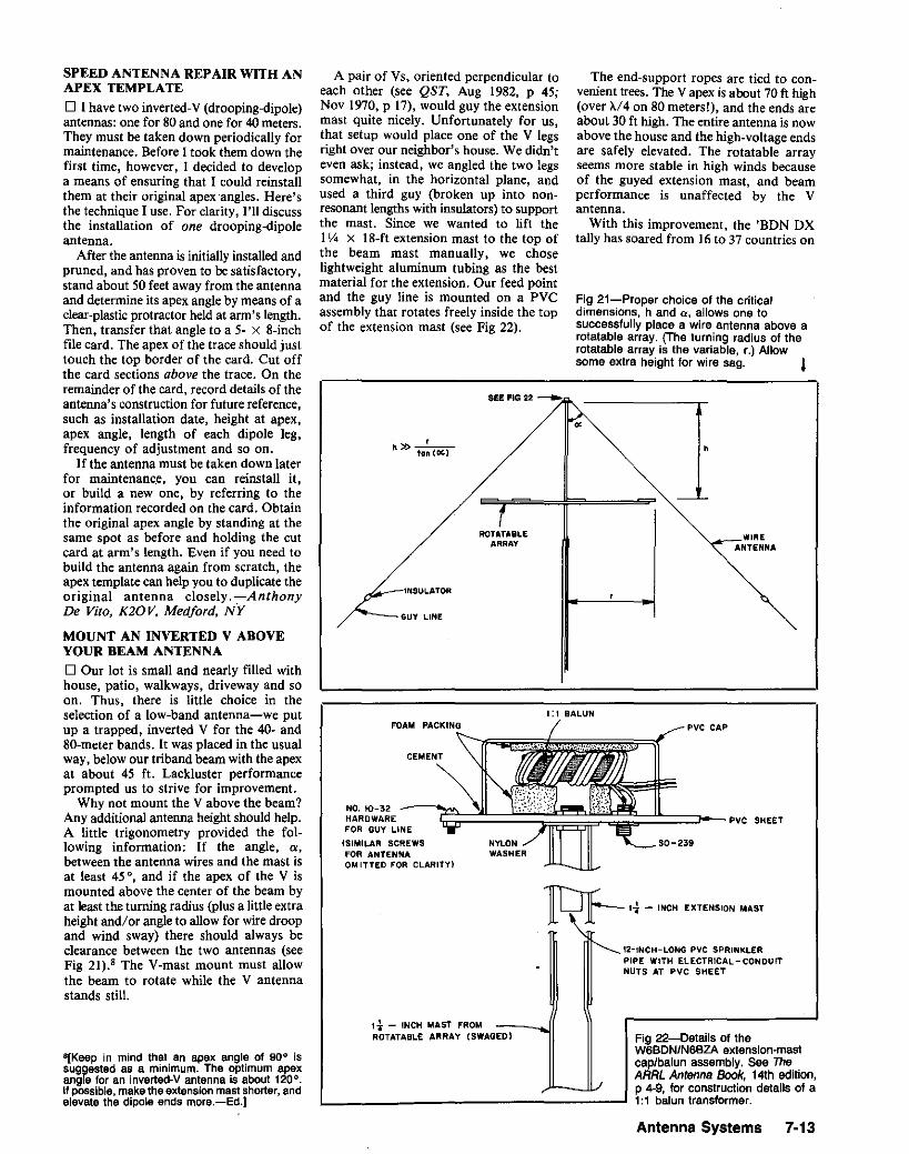
1:1 BALUN
lQf-- 'i - 'NCH EXTENSION MAST
pvc CAP
SO-239
12-INCH-LONG PVC SPRINKLERPIPE WITH ELECTRICAL-CONDUITNUTS AT PVC SHEET
The end-support ropes are tied to convenient trees. The V apex is about 70 ft high(over >"/4 on 80 metersl), and the ends areabout 30 ft high. The entire antenna is nowabove the house and the high-voltage endsare safely elevated. The rotatable arrayseems more stable in high winds becauseof the guyed extension mast, and beamperformance is unaffected by the Vantenna.
With this improvement, the 'BDN DXtally has soared from 16 to 37 countries on
WIREANTENNA
Fig 21-Proper choice of the criticaldimensions, h and a, allows one tosuccessfully place a wire antenna above arotatable array. (The turning radius of therotatable array is the variable, r.) Allowsome extra height for wire sag. l
NO. 10-32HARDWAREFOR GUY LINE
(SIMILAR SCREWSfOR ANTENNAOMITTED FOR CLARITY I
INSULATOR
A pair of Vs, oriented perpendicular toeach other (see QST, Aug 1982, P 45;Nov 1970, P 17), would guy the extensionmast quite nicely. Unfortunately for us,that setup would place one of the V legsright over our neighbor's house. We didn'teven ask; instead, we angled the two legssomewhat, in the horizontal plane, andused a third guy (broken up into nonresonant lengths with insulators) to supportthe mast. Since we wanted to lift the11,4 x 18-ft extension mast to the top ofthe beam mast manually, we choselightweight aluminum tubing as the bestmaterial for the extension. Our feed pointand the guy line is mounted on a PVCassembly that rotates freely inside the topof the extension mast (see Fig 22).
ROTATABLEARRAY
rh» tan {ClC.1
SEE FIG 22 ----.
GUY LINE
SPEED ANTENNA REPAIR WITH ANAPEX TEMPLATE
o I have two inverted-V (drooping-dipole)antennas: onefor 80and onefor 40meters.They must be taken down periodically formaintenance. Before I took them down thefirst time, however, I decided to developa means of ensuring that I could reinstallthem at their original apex "angles. Here'sthe technique I use. For clarity, I'll discussthe installation of one drooping-dipoleantenna.
After the antenna is initially installed andpruned, and has proven to be satisfactory.stand about 50 feet away from the antennaand determine its apex angle by means of aclear-plastic protractor held at arm's length.Then, transfer that angle to a 5- x 8-inchfile card. The apex of the trace should justtouch the top border of the card. Cut offthe card sections above the trace. On theremainder of the card, record details of theantenna's construction for future reference,such as installation date, height at apex,apex angle, length of each dipole leg,frequency of adjustment and so on.
If the antenna must be taken down laterfor maintenance, you can reinstall it,or build a new one, by referring to theinformation recorded on the card. Obtainthe original apex angle by standing at thesame spot as before and holding the cutcard at arm's length. Even if you need tobuild the antenna again from scratch, theapex template can help you to duplicate theoriginal antenna closely.-AnthonyDe Vito, K20V, Medford, N'Y
MOUNT AN INVERTED V ABOVEYOUR BEAM ANTENNA
o Our lot is small and nearly filled withhouse, patio, walkways, driveway and soon. Thus, there is little choice in theselection of a low-band antenna-we putup a trapped, inverted V for the 40- and80-meter bands. It was placed in the usualway, below our triband beam with the apexat about 45 ft. Lackluster performanceprompted us to strive for improvement.
Why not mount the V above the beam?Any additional antenna height should help.A little trigonometry provided the following information: If the angle, o,between the antenna wires and the mast isat least 45°, and if the apex of the V ismounted above the center of the beam byat least the turning radius (Plus a little extraheight and/or angle to allow for wire droopand wind sway) there should always beclearance between the two antennas (seeFig 21).' The V-mast mount must allowthe beam to rotate while the V antennastands still.
8[Keep in mind that an apex angle of 90° issuggested as a minimum. The optimum apexangle for an inverted-V antenna is about 120°.If possible,makethe extensionmastshorter,andelevate the dipole ends more.-Ed.]
1l- - INCH MAST FROMROTATABLE ARRAY (SWAGED) Fig 22-Details of the
W6BDN/N6BZA extension-mastcaplbalun assembly. See TheARRL Antenna Book, 14th edition,p 4-9, for construction details of a1:1 balun transformer.
Antenna Systems 7·13

Fig 23-KA6UXR's movable wire-antenna extensions make antenna adjustment convenient.
3/8-INCH- DIAMETERPLASTIC TUBE
the tubing "just right" for such a job isn'tjust right because the slip joint is too loose.Here is a solution I developed while constructing a two-section. push-up antennamast from 1Y2- and 1!!.I -inch thin-wallelectrical conduit.
First, remove the cutting blade from apipe cutter that is large enough to cut thetube you wish to form. Purchase or fabricate a new steel roller (Fig 24). The new
TAPE PLASTIC TUBETO GUY UNE
GUY LINEPLASTICPIPE COUPLER
1/4 -INCH-DIAMETERHOLES
PIGTAIL
ALLIGATORCLIPS
SOLDER
ANTENNA
Fig 25-Use the new roller to groove thelarger tube of a slip joint. This reduces thetube's inner diameter slightly to provide asnug fit with a smaller tube.
Fig 24-The original cutting roller (A) and anew forming roller (B) used to work tubingfor a snug fit. (The exact shape of the newroller is not important. It should be groundfrom solid steel and have the same hubwidth and outer diameter as the cuttingroller it replaces.)
",.)lA)
blade rolls a groove (Fig 25) in the pipe ortubing instead of cutting it. Install the newroller in the pipe cutter.
Use your new forming tool to tightenloose slip joints in this way: Place one tubeinside the other and use the modified pipecutter to roll two or more grooves in thelarger tube. Continuously turn and slide thesmaller tube to test the fit. Stop when thereis a noticeable increase in the frictionbetween the two tubes. (If you roll thegroove too deeply, the two tubes will bepermanently honded together! This methodis useful, however, for locking two piecesof tubing together.)
Application of this method is not limitedto large tubes or thin-wall tubes. A similarlymodified small tube cutter works withdiameters as small as Y<l inch. I have usedthe larger tool to groove standard 1~ -inchwater pipe. No doubt it would work justas well with heavier (schedule 80)pipe. Myown problem I encountered using thismethod has been an occasional split seamwhile I was experimenting to see howdeeply I could groove welded tubing.-J. M. Simms, N7BBC, Tucson, Arizona
insulators can be found at almost any feedstore that carries electric cattle fencesupplies. Known as corner post insulators.they cost about $2 for a package of 10. I'veused several for over a year, and weatherdoes not seem to bother them.-Frank A.Reed, Jr, W6PWQ, Langlois, Oregon
MODIFIED WORK GLOVESo Did you ever suffer from frosty fingersduring tower climbing and antenna workin cold weather? Not only is cold metaluncomfortable, but numb fingers make iteasy to drop small parts. Gloves just seemto get in the way.
Try cutting the fingertips from a pair ofinexpensive work gloves. (Cheap cottongloves are fine.) Cut off the glove fingersmidway betweenthe first and second joints.Gloves modified in this way will protectyour hands for grasping and holding whilekeeping your fingertips free for delicatework.-Ray Lustig, KD3A, Washington,DCEditor's Note: Aus Healy,NJ2L, of the AARL HQstaff, adds that cycling gloves can also servethispurpose. These gloves have padded leatherpalms and no fingers, and usually cost from $10to $20.Theyareavailable frommostbicycleshopsand mail-order suppliers of cycling equipment.
MORE ON MODIFYING GLOVES FORINCREASED DEXTERITY ANDBETTER FEELo When I read the suggestion aboutcutting the fingertips from work gloves itreminded me of something that may be offurther value to your readers. As a policeofficer, I've learned a trick passed downfrom the old timers on the force: Cut a slitinto the palm side of the glove's triggerfinger to allow your trigger finger to slipout when you hold a pistol. Of course. thismodification also allows the finger to bereturned to the glove!
For doing antenna work in cold weather,a pair of gloves modified this way (perhapsthe thumb and first finger of each glove,or at least these fingers on the glove for thedominant hand) would allow these fingersto f)e kept warm between instances ofhandling small parts.-Harry Blesy,N9CQX, 78/0 Central, River Forest, IL60305
MAKE A SNUG FIT FORTELESCOPING TUBING
o In many antenna projects, it is desirableto have two pieces of metal tubing with asnug telescoping fit. Quite often, I find that
ALTERNATIVE ANTENNAINSULATORSo I never seem to have any antenna insulators handy when I need them. Plexiglas isgood, but cutting and drilling it is notalways practical (on Field Day, forexample).
If great strength is not required and theinstallation is temporary, I use Wiffle practice golf balls. They work well and are farless expensive than porcelain insulators.-Bob Raffaele, W2XM, Albany, NewYork
"PIGTAILS" MAKE ANTENNAADJUSTMENT EASYo Wire-dipole and inverted-V antennasoften need trimming in place, even whencarefully cut to calculated measurements.They are easy to shorten, but one may trimoff too much, or the calculated length maybe too short in the first place. Aside fromthe initial setup, resonance may drift overtime for electrically obscure reasons.Antenna stretching is difficult!
After patching wire onto the ends ofseveral antennas, I developed a versatileadjustment system. First, use only barewire for the antenna, and cut it somewhatshorter than the calculated length. [Try2-3"10.-Ed.] Next, attach the antenna endsto the guy lines with an insulator made bydrilling a plastic pipe coupler with !!.I-inchholes for the antenna wire and guy (Fig 23).Make a pigtail (extension) from the samewire as the antenna and long enough to wellexceed the calculated antenna length.[Again, 2-3"1o.-Ed.] (The antenna shouldbeslightlytoo short without the pigtails, butslightly too long with them fully extended.)Solder a couple of alligator clips at 90 0 toeach pigtail as shown in the figure. Insertthe pigtails through the insulators and attachthe alligator clips to the antenna ends.
The antenna resonant frequency is noweasily adjusted by moving the pigtails alongthe antenna ends. The pigtails appearweather resistant, and they make antennaadjustment easy.-Alex Comfort, MD,KA6UXR, Ventura, California
75 meters! So try giving your inverted V alift!-Martin, W6BDN, and Daniel,N6BZA, Levin, Menlo Park, California
ELECTRIC·FENCE INSULATORSALSO WORK FOR ANTENNASo A good substitute for "egg'.!---8kain
7·14 Chapter 7

AN INEXPENSIVE CONCRETECUTTER
o My problem wasn't a difficult one. AllI needed was a 22-inch-square cut inconcrete so my tower would fit along oneside of my driveway. I checked into havingsomeone cut the hole for me. Wow! Pricesranged from $80 to $105-so much forthat! Renting a cutting machine looked abit better: $55 plus the cost of the cuttingblade. But jump up cow-that's more thanhalf of what a rotator, or enough bags ofconcrete for the tower base, would cost!
The solution-simple and cheaper thanthe first two options-came to me onenight as I lay in bed waiting for thatsandman character. I realized that aconcrete-cutting machine looks like aheavy-duty grass edger. Would a grassedger work? I tried it! I changed the oil onmy edger (cost, $1.25) and installed a newbelt ($4.17, and the edger needed itanyway). With the help of a IO-inchdiameter masonry-cutting blade ($3.88),water from the garden hose, two or threehours' worth of patience, sun, breaks andbeer. the job was all but done. Then. withthe help of a 16-pound sledge, 1 finally hit,er, pay dirtl-Steve Grimminger, KG6KL,6107 Whitewood, Lakewood, CA 90712
WARNING ON USING A GRASSEDGER TO CUT CONCRETE
o After reading Steve Grimminger's "AnInexpensive Concrete Cutter," I feelobliged to sound a cautionary noteconcerning the use of a grass edger as amakeshift concrete saw. While most of ushave at one time or another been guilty ofmisusing a tool, this is a misuse withpotentially deadly consequences!
All nonmetallic cutting and grindingwheels and blades consist of an abrasive/bonding-agent composition. Used asintended, they are relatively safe andeffective tools. Used improperly, they havea nasty habit of disintegrating and sendingshrapnel in all directions, sometimesmaiming. disfiguring or killing the sawoperator. Having worked in the industrialmaintenance field for many years, take myword for it that you don't want to becomethe target of an exploding abrasive sawblade!
While I know nothing of the construction (guards, rotational speed, and 50 on)of the edger used by KG6KL, one thing issure: It wasn't designed to be used as amasonry saw. So, even though the cost ofrenting or buying a concrete saw for a smalljob may seem prohibitive, you can't put aprice on your safety, or that of thosearound you. In the long run, it pays to usetools only for their intended purpose.-Roger Burch, WF4N, Rt 3 Box 235,Central City, KY 42330
TOWER ANTI-CLIMBING SHIELDS
o Fig 26 shows a practical safety solutionto discourage unwanted climbers on atower: an anti-climbing shield. In this case,
the shield is installed on a Rohn HDBX48tower. but should be readily adaptable toother towers as well.
The shield consists of three 2 x 8-footsheets of corrugated fiberglass roofing,metal plumbing straps and three bolts withwing nuts. The nuts and bolts hold thestraps in place; the wing nuts face outwardto allow removal when necessary.
This safety solution is inexpensive. usesreadily available materials, and is pleasingto the eye. Most importantly, it removesthe temptation for unwanted (usuallyyoung) visitors to climb the tower.-BettyOakberg, N4LZL, 105 Ulena Ln, OakRidge, TN 37830
o Radio antennas fall under the categoryattractive nuisance because they form irresistible temptationstoneighborhood adventurers. Virtually everytower, in town ornot, needs somemeans of foiling unauthorized climbers.A simple and fairlyinexpensive guardcan be made from
Fig 26-(left) Betty Oakberg uses thisfiberglass-roofing guard to keep unwantedclimbers off her tower. Betty's son Frankinstalled this guard in just a few minutes.
Fig 27-(above right) Robert Brown's anticlimbing towerguard consistsof 1 x 10sprucelumber, paint, nuts and U bolts. See text.
1 x 10 or 1 x 12 rough-sawn spruce, asshown in Fig 27. This material is smoothfinished on one side and rough-finished onthe other. Mount the lumber with itssmooth side facing the inside of the tower;
the rough sides of the boards should faceoutward to afford splintery discouragementto would-be steeplejacks. Attach eachboard to the tower with a pair of U bolts,one bolt on each end of each board.
The guard shown in Fig 27 cost mearound $25 to build. Such a guard can beconstructed in one afternoon, and, ifpainted to match its background, isunobtrusive to neighbors (most of whomprobably tend to regard antennas less asthings of beauty than radio amateursgenerally do). Incidentally, spruce must bepainted for weather resistance; protected inthis way, it can last for decades.-RobertE. Brown. WA9MRU, 309 S MinnesotaA ve, Morton, IL 61550
UNIVERSAL JOINTS PREVENTANTENNA·MAST BINDING
o Aligning a rotator with a mast so thatno binding occurs when the mast turns canbe frustrating and time-consuming. Evena slight misalignment can cause the mastto bind in the tower thrust bearing, possiblycausing damage to the rotator motor.
I solved this alignment problem by usingtwo universal joints (U joints) to couple therotator to the mast (Fig 28). The universaljoints are installed so that their pivotdirections are offset by 90°. The U jointspermit the mast to remain vertical in thetower while accommodating considerablemisalignment between the rotator andmast.
The U joints shown in Fig 28 are froma NATCO multiple boring machlne and are
Fig 28-Jay Lowe uses two universal jointsto correct misalignment between his rotatorand antenna mast. (photo by Jack McCann,KD0SV)
Antenna Systems 7-15

approximately 7/8 inch in diameter.Similar U joints, used in farm machineryand power take-off units, are available atfarm-implement or hardware stores for $2or less. A short length of l-inch-diameterpipe, drilled to pass the rotator-to-jointbolt, couples the rotator to the lower Ujoint; the antenna mast is coupled to theupper U joint in this way. The U joints arecoupled by a metal rod of suitablediameterand length.-Jay Lowe, KA6RKR. 390/Missouri, Joplin, MO 6480/
ITS' A STANDOFFo Here's a versatile, low-cost tower sidemount for UHF and VHF verticalantennas(Fig 29). You can find all of the materialnecessary to build it-a lO-foot length of¥i-inch-diameter. thin-walled steel electrical conduit and two stainless-steel hoseclamps-at any well-stocked hardwarestore. My standoff cost me a total of $5.50.
Make the standoff's two included angles(e in Fig 29) 90 0 or more to keep thehorizontal part of the conduit from trapping water. (If you ask nicely, the hardware-store staff may even bend the conduitfor you.) Put a plastic cap on the upperpipe end to keep water out. Also, be sureto make the standoff's lower verticalportion at least 36 inches long so you canclamp it inside your tower. Other thanoffering these two suggestions, I leave thestandoff's construction particulars up toyou.
Experiment with the standoff at groundlevel to fmd a mechanically sound mountingmethod. On my Rohn 25 tower, passingtheconduit through a rung openingand nestingthe horizontal portion in the lower crotchof a diagonal brace gave the most stability.
Once you've determined how to mountyour standoff, use the hose clamps tofasten the standoff's 36-inch verticalposition to the insideof the back tower leg.(Be sure to position the clamp's tighteningscrew and clamp-band tail inside the towerleg: Metal protruding outside the leg couldbe dangerous to someone climbing thetower.)
Next, mount your antenna and feed lineto the standoff. Once you've done this,adjust the standoff's bends so that everything is square with the world (unlessyou're not bothered by a nonverticalvertical antenna!). If everything passesinspection, mount the standoff/antennacombination in its final position on thetower.-Mike Ettenhofer, WB8VDG, AnnArbor, Michigan
PVC-PIPE GUY PROTECTORSD I agree with Earl Anderson ("WrapYour Guy Lines," Hints and Kinks, QST,Oct 1986, p 48) that guy cables should bevisible. I prefer not to use pipe-insulatingsleeves for guy protectors, though: Thesleeves' foam material absorbs water andkeeps a wet surface in contact with eachprotected guy for prolonged periods,
7-16 Chapter 7
HOlleClompa
Fig 30-Eliott Hood holds his PVC-pipeprotectors in place with steel wire.
speeding guy rusting.Here are two alternative solutions.
K·Mart and other stores carry slip-overshower-curtain rod covers that can easilybe slipped over existing guys; these coversare available in a number of highly visiblecolors. They are made of a plastic thatbrittles after four or five years of exposureto sunlight,
A better solution that's most easilyadded
ccccec~ "'..'.•".;.jlk~"l
Conduit
Fig 29-Mike Ettenhofer uses a lengthof electrical conduit and two allstainless-steel hose clamps to sidemount a vertical VHF antenna on histower. Make e greater than 900 tokeep the standoff from trapping waterin its bends. If you cap the tubebottom, drill a hole in the cap to allowcondensation to escape.
to yet-to-be installed guys, or to guys thatcan be temporarily detached at groundlevel, is %-inch-ID, white-PVC pipe.Purchase a 20-foot section of pipe-minecost about $4-at your local plumbingsupply house and cut it to size (5-footlengthsare suitable).Fig 30 showshow steelcross wires can be used to attach the pipeto the guys. I used O.04I-inch, stainlesssteel, safety-lock wire for this purpose; asingleguy-wire strand may also work. (Youmay be able to install PVC-pipe guy sleevesover undetachable guys by slitting the pipelengthwise with a table saw. Properlyplaced, the cross wires can serve to closethe resultant slits.)
After you've twisted the cross wiresenough to give the protector a sufficientlytight grip on the guy cable, position theprotector on the guy as appropriate. (Leavethe twisted cross-wire ends long enough sothat they can be bent back inside the PVCtube.)
If you intend to paint your protectors,I suggest roughening the pipe's outersurface slightly with PVC-pipe solvent orsandpaper prior to painting.-E//iottHood, NE9I, 5627 Danbury Dr, SouthBend, IN 466/4
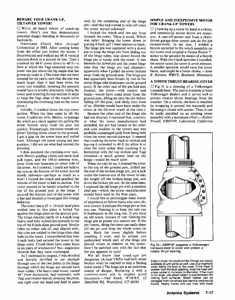
BEWARE YOUR CRANK-UP,TILT·OVER TOWERI
o We've all heard stories of crank-uptowers. Here's one that demonstratespotential danger standing in thousands ofbackyards.
Hurricane Gloria blew throughConnecticut in 1985. After coming homefrom the office just before the storm, Idisconnected and walked my 48-ft verticalantenna down in a minute or less. Then Icranked my 60-ft tower down to 40 ft-alevel at which the Vagi mounted atop thetower was just above the big maple that hasgrown up under it. (The tower had not beenlowered for six years; now that the tree wasmuch larger than it had been when thetower was installed, lowering the antennawould have to involve alternately tilting thetower and lowering its top section in stepsto keep the Vagi clear of the maple whileminimizing the overhung load on the towerpivot.)
Initially, I cranked down the top towersection. When the time came to tilt thetower, I called my wife, Shirley, to managethe winch as a check against my pulling thetower bottom away from the post tooquickly. Frustratingly, the tower would notpivot! Getting down closer to the ground,I got a grip on the tower base and pulledhard. Although the tower swung out intoposition, I did not see what had resisted thepivoting.
I then assumed the cranking-over task,with Shirley guiding cables and latch-lockpull ropes, and the 160-m antenna wire,away from tree branches on either side ofthe tower. As I cranked, I could not believemy eyes as the bottom of the tower movedslowly sideways-perhaps as much as afoot! I locked the winch and grabbed thebottom of the tower to halt its motion. Thetower seemed to be barely attached to thetop of the ground post at the hinge. Isecured the bottom end of the tower witha line and decided to investigate this strangebehavior.
The tower has a 10 x 10-inch steel platewelded into it; this plate is bolted flatagainst the hinge plate on the ground post.The hinge consists partly of a 4-inch-longheavy steel tube welded horizontally to thetop of the 8-inch-diam ground post. Similartubes on either side of, and aligned with,this tube are welded to the hinge plate thatbolts to the tower. I remembered that fourI-inch bolts had secured the tower to thehinge plate. Could these have come loosein six years of windstorms? No-inspectionshowed that they were unchanged.
As I continued to inspect, I was shockedand literally terrified to see daylightthrough one of the two joints in the hingethrough which the hinge pin should havebeen visible. The heavy steel tower, canted40° from horizontal, half extended, withYagiand rotator heavilystressing thepivot,was right over my head and held in place
only by the remaining end of the hingepin-and that had started to twist off whenthe tower moved sideways!
I locked the winch and ran out frombeneath the tower. There it stood. Whichwas safer: Bringing the tower down orputting it back up? I went indoors to think.The hinge pin was equipped with a dowelpin to keep the hinge pin from sliding outof the hinge tubes; that dowel forced thehinge pin to rotate with the tower. It wasbetween the dowel pin and the center hingetube that the hinge pin had shearedapparently when I pulled the tower bottomaway from the ground post. The hinge pinhad apparently been frozen by rust in thecenter hinge tube (stationary on the groundpost). If the other end of the pin had alsosheared, the tower-with rotator andbeam-would have come loose from theground post, lifting me into the sky beforefalling off the post, and likely onto bothof us. (Shirley would have been under thetower at the tilt-over crank at the time.)
Because the other end of the hinge pinhad not sheared, I reasoned that, contraryto what the tower manufacturer hadintended, the pin had turned in the otherend tube (welded to the tower) and wasprobably undamaged aside from being bentwhen the tower moved sideways. It seemedthat cranking the tower back to vertical andleaving it extended to 40 ft (to allow it toclear the tree) rather than cranking it tohorizontal with the top section and Vagiextended-a much greater load on thehinge-would be much safer.
When the rain let up, I chained the towerto the top of the ground post, drilled outthe end of the broken hinge pin, put a jackunder the bottom end of the tower to takethe weight off the broken hinge pin, anddrove the broken pin out. At the same time,I replaced the old hinge pin with a stainlesssteel pin-which the tower manufacturershould have used in the first place.
I would like to promulgate some wordsof experience to fellow hams who own tiltover towers: Lubricate the hinge pin as bestyou can. Painting it to keep the rain outis inadequate in the long run. If you havean old tower, beware of rust freezing thehinge pin at points you cannot see. If thepin freezes, tilting the tower can easily shearoff the pin and drop the whole tower onyou. Rock the tower slightly beforecranking it over, and be certain youunderstand which part of the hinge pinshould rotate in relation to the tower.Don't be satisfied only with the fact thatthe pin appears to turn!
We all know that crank-ups aredangerous. (A local VHFer had both wristsbroken when he reached to stop a flailingtower crank.) The hinge pin is an inobvioussource of danger. Replacing it with astainless-steel pin is mighty goodinsurance.-Ned Raub, WIRAN, 12Deerfield Rd, Waterford, CT 06385
SIMPLE AND INEXPENSIVE MOTORFOR CRANK·UP TOWERS
o Cranking up a tower by hand is a chore,and commercial motor drives are expensive. A cast-off power unit from a chaindriven garage-door opener can do the jobinexpensively. In my case, I welded abicycle sprocket to the winch assembly onmy tower and coupled a Perma Power ®
motor to the sprocket by means of a bicyclechain. With the 6-inch sprocket I installed,the motor raises the tower in seven minutes.A smaller sprocket would raise the towerfaster, and might be a better choice.-JohnR. Kersten, Wt>NY, Brainerd, Minnesota
A TOWER THRUST·BEARING COVER
o Fig 31 is a drawing of a Volkswagentransaxle boot. The part is available at localVolkswagen dealers and it serves well toprotect rotator thrust bearings from theweather. On a vehicle, the boot is installedby wrapping it around the transaxle andfastening it closed with screws. Thus, it canbe easily installed on an existing towerassembly with a minimum effort.-RobertPowell, KB6FNP, Lakewood, California
Fig 31-KB6FNP suggests a Volkswagentransaxle boot to cover and protect arotator thrust bearing.
Editor's Note: No doubt similar fittings are readilyavailable at junk yards as well. Use your ingenuitywhen fitting the boot to the mast. If the mast issmaller than the boot opening, wrap the mast withsheet rubber to increase its diameter. If the mastis too large, use sheet rubber to pad between themating boot surfaces. Sheet rubber can besalvaged from tire shops that service commercialtrucks. Heavy trucks still use tires with inner
Antenna Systems 7·17

to Control Box
Terminal 2(Red)
r-----------.-__-/l Terminal 1l (Block)
PIN4
'--1~+--'-<PIN3
rotator control by means of push buttonSI, VERNIER DRIVE. Use the normal modeto position your V-loo to the 100 incrementnearest the heading (elevation) you need.Then select the vernier mode and use S1 tofine-position the rotator to where you wantit.
When S2 is set to VERNIER and the indicator is between clicks, the controller's pilotlamp lights more brightly than normal. Iconsidered adding a switch to prevent lampburnout, but after using the modified controller for over a year I still haven't hadto replace the bulb.-Dave Guimont.WB6LLO. 5030 July St, San Diego, CA92110
VACUUM TUGS LEADER ROPETHROUGH CONDUIT
o I run the wires to my tower undergroundthrough a conduit. Because the conduit is
T1DL 24-12 12A
r--o-~"""fo
AC toOL -e.e-o.e
'---1 xFMR
1N4003
Fig 33-Dave Guimont adds switch-selectable position-vernier operation to his AllianceU-100 rotator by installing two switches-a double-pole push button (51) and a OPOltoggle (52).
Fig 32-Delayed automatic braking for the Hy-Gain HDR 300 rotator. T1 is shown wiredfor 120 V BC. K1 is a 28-V de relay; 51 is a 3POT, center-off toggle rated for 120 V BCservice; U1 is a 4 A, 100-PIV bridge rectifier. Resistors are Vz-W carbon film.
troller in 100 steps-acceptable resolutionfor wide-beamwidth antennas, but somewhat coarser than optimum for most 70and 24-cm antenna arrays. Many satellite-active V-l00 users modify their controllers for finer resolution by installing adouble-pole, normally open push button inthe control wires connected to the controller's terminals 1 and 2. Using this feature requires that the push button be helduntil the desired elevation is achieved-aninconvenience to V-l00 users because it'sa comedown from the controller's standardoperation, which automatically moves therotator to the heading you preset.
Fig 33 shows how to add an additionalswitch that allows you to toggle betweenposition-vernier and set-and-seek operationwith the U-IOO. Set to NORMAL, S2 (MODE)selects the U-IOO's standard set-and-seekoperation. Setting S2 to VERNIER selects
tubes-the discarded tubes are a good source ofrubber(about 3/32-inch thick).
Frugal readers may wish to fabricate a customthrust-bearing boot by wrapping the mast!bearing with sheet rubber. Cut a sectionof rubberlarge enough to cover the bearing and wrap itaround the mast. Secure the seam(s)with no. 6or no. 8 hardware. Use a hose clamp to fastenthe assembly in place on the mast and seal theassembly with RTV.
NOISE-SUPPRESSION AND BRAKECONTROL MODIFICATIONS FORTHE HY-GAIN HDR 300 ANTENNAROTATORo After installing my Hy-Gain" HDR 300rotator, I observed that a new noise sourcehad appeared on 6 meters. I traced thenoise to the HDR 300: The noise emanatedfrom the ribbon cable associated with therotator's multiplexed LED display! I solvedthis problem by wrapping aluminum foilaround the ribbon cable and wrapping barewire around the foil. After taping the foilwire sleeve in place and dressing it to keepit out of contact with other HDR 300wiring, I grounded the sleeve wire tocommon on both of the HDR 300's PCboards. RFI problem solved!
The second HDR 300 problem I solvedwas one of my own doing: Sometimes, Ileft the brake off with the rotator turnedon. Because my antenna stack is largeenough to windmill in a strong wind, Iworried that damage might occur if I leftit unbraked. This problem can be solvedas follows:
Replace the HDR 300's stock SPDTRIGHT/LEFT switch with a 3PDT, center-offunit. Wire this switch as shown in Fig 32.One of the additional two poles goesbetween the HDR 300's POWER and BRAKE
switches; the third pole serves as part ofadded brake-control circuitry (also shownin Fig 32).
Whenever SI (RIGHT/LEFT) is thrown andthe rotator BRAKE switch is on, the voltageat the secondary of Tl is rectified, chargingthe l00-JLF capacitor and turning on Ql.Ql actuates Kl. When SI is released, therotating motor stops and the path betweenVI and QI's base circuitry is cut by SIC.Q I, K1 and the rotator brake solenoidstay on, however, because of the chargeremaining on the l00-JLF capacitor. Whenthe capacitor discharges sufficientlythrough the lOO-kll resistorto turn off QI,KIA opens, cutting ac mains current to thebrake solenoid and engaging the brake.
With the RC values shown in Fig 32, thedelay between opening the RIGHT/LEFT orBRAKE switch and engagement of thebrake is about 7 seconds. This allows therotating antenna stack to coast to a stopbefore the brake engages.-Paul D'Anneo,K6UZK, 6126 Ocean View Dr, Oakland,CA 94618
SMOOTHER CONTROL WITH THEU-tOO ROTATOR
o The Alliance U-lOO rotator, popularamong satellite enthusiasts as an elevationrotator, can be positioned by its stock con-
7·18 Chapter 7
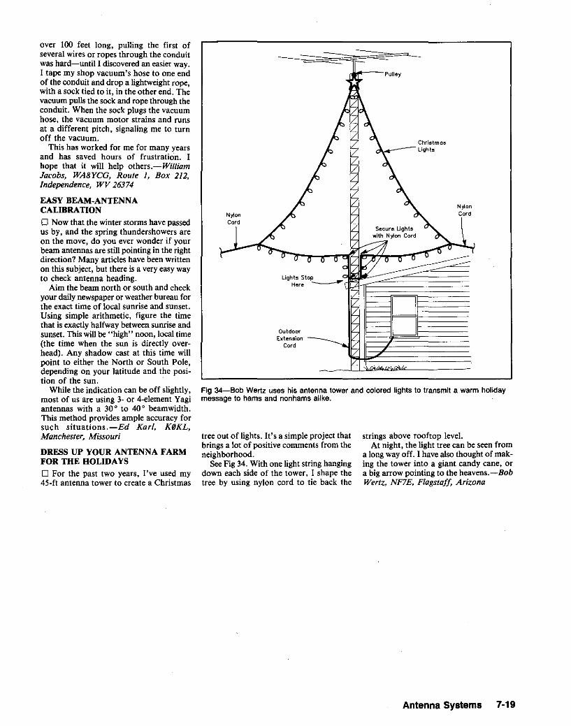
Jl"O---Pulley
Fig 34-Bob Wertz uses his antenna tower and colored lights to transmit a warm holidaymessage to hams and nonhams alike.
over 100 feet long, pulling the first ofseveral wires or ropes through the conduitwas hard-until I discovered an easier way.I tape my shop vacuum's hose to one endof the conduit and drop a lightweight rope,with a sock tied to it, in the other end. Thevacuum pulls the sock and rope through theconduit. When the sock plugs the vacuumhose, the vacuum motor strains and runsat a different pitch, signaling me to turnoff the vacuum.
This has worked for me for many yearsand has saved hours of frustration. Ihope that it will help others.-WilliamJacobs, WA8YCG, Route 1, Box 212.Independence, WV 26374
EASY BEAM-ANTENNACALIBRATION
o Now that the winter storms have passedus by, and the spring thundershowers areon the move, do you ever wonder if yourbeam antennas are still pointing in the rightdirection? Many articles have been writtenon this subject, but there is a very easy wayto check antenna heading.
Aim the beam north or south and checkyour daily newspaper or weather bureau forthe exact time of local sunrise and sunset.Using simple arithmetic, figure the timethat is exactly halfway between sunrise andsunset. This willbe"high" noon, local time(the time when the sun is directly overhead). Any shadow cast at this time willpoint to either the North or South Pole,depending on your latitude and the position of the sun.
While the indication can be off slightly,most of us are using 3- or a-element Vagiantennas with a 30 0 to 40 0 beamwidth.This method provides ample accuracy forsuch situations.-Ed Karl. KIJKL.Manchester, Missouri
DRESS UP YOUR ANTENNA FARMFOR THE HOLIDAYSo For the past two years, I've used my45-ft antenna tower to create a Christmas
Here ----r
OutdoorExtension
Cord
tree out of lights. It's a simple project thatbrings a lot of positive comments from theneighborhood.
See Fig 34. With one light string hangingdown each side of the tower, I shape thetree by using nylon cord to tie back the
ChristmosLights
N)tonCord
B
strings above rooftop level.At night, the light tree can be seen from
a long way off. I have also thought of making the tower into a giant candy cane, ora big arrow pointing to the heavens.-BobWerlz. NF7E. Flagstaff, Arizona
Antenna Systems 7·19

ROTATABLE ANTENNAS
(A)
Fig 37-Details of the mounting-plate assembly (A) and element joint (8). Flatten the jointslightly after assembly to prevent rotation.
aOOM
(8)
FLATTEN JOINTTO PREVENT
A ROTATION
lSELF-
/\
' THREADING
ISCREW
"ECE_
A~
IORK ~
PIECE~ :::J SECTION A-A
J oe t,
* TIE PLASTIC - DowEL JOINTTO BOOM WITH ROPE ASSHOWN
SELF - THREADINGSCREWS AT FEED POINT
JUMPER
TRY A SIGMA BEAM ON YOURSMALL LOT![Editor's Note: An article: describing JG1U,NE'sSigma beam appeared In the Feb 1980 Issue(p 280) of Japan's CQ Ham Radio magazine.)
o A full-size beam antenna is great-ifyou have the space for one. Many of us,however, live in apartments and just don'thave that space. Figs 35 through 38 describethe results of my experiments with aminiaturized beam antenna in a E (sigma)configuration. My antenna is mounted atthe top of a tower, about 15 m above thebuilding roof.
Fig 35-JG1UNE's Sigma beam. Tubesizes and lengths appear in Table 2.
The Sigma beam is a compact antennashaped like the Greek letter sigma; it is aV beam with the element ends bent toreduce its size. A list of materials for a28-MHz antenna, constructed of aluminumtubing, appears in Table 2. Be sure to flatten the tube joints (lifter assemblyl) to keep
the element ends from rotating (see Fig 378and Section A-A).
My beam was a little heavy when all elements were made of metal tubing. Also, thetube joints are weak points, which arethreatened by strong winds. The antennaweight can be reduced, and constructionsimplified, if we use straight bamboo orfiberglass spreaders to support wire elements. Two such antennas are shown in
Fig 38. [This also eliminates any overlapproblems where the element centers crossat the boom. Use nylon twine or some otherinsulating material for the lines at the element ends.-Ed.]
An SWR plot of my Sigma beam compares well with that of a full-size, twoelement V beam. The two curves are nearlyidentical, with the SWR less than 1.7:1from 28 to 29 MHz. The folded element
I"400mm
I'i.
1+ + 1181
I181 E
'i. / -, I V "'181E, Y 40mm~181
1-+1/\ '>~~ + '~'/'~J4l rr18 18
mm mm
Fig 36-Drilling pattern for the mounting plate. [Dimensions are in mm; inches "" mm x 0.0394. Size holes and adjust locations to fitlocally available hardware. The mounting plate may be hardwood rather than plastic, or plastic sleeves may be used to insulate theelements from a metal plate if a plastic plate is not available.-Ed.)
7·20 Chapter 7

6"~LONG
PLASTIC HOS!
i--NO.6 SCREW
~__ STAR WASHER
'
3/8"~W1DE COPPER SHEETFOR AOJ CONTACT POINT
__WASHER
__ NUT
,
fl'~ '~
• TO" _BALUN
Fig 40-Construction details of theindividual hoops. The plastic hose must fittightly over the copper tubinq in order tohold the ends in place (A). Make twosliding clamps to feed the antenna (8).[Use stainless steel hardware to preventcorrosion.-Ed.] Place one clamp on eachhoop, and position them on opposite sidesof the hoop center line (also see Table 3).
Fi9 39-A photo of KA9LYR's completedloop antenna.
A DOUBLE HALF-WAVE LOOPANTENNA
IHere is some modern information on anInteresting antenna that has been in TheARRLAntenna Book for years.-Ed.)o Fig 39 shows an effective, easy to buildand inexpensiveHF antenna. The plans arefrom an old issue of QST that I bought atthe Wheaton Community Radio Hamfestin 1984.' The more I read about thedouble half-wave loop, the more interestedI became; so I decided to give it a try. Thisantenna can be built for any band (seeTable 3), but I decided to try it forIS meters, because of the convenient size.Table 4 is a materials list for the IS-meterantenna. Because the antenna is 85 incheswide, I suggest that it be assembledoutdoors. The necessary materials can befound at most local hardware stores.
For IS-meter operation, the hoopsshould have a circumference of about22.1 ft, with a 3-inch end gap. Each loopis made of Yo -inch (ID) copper tubing.Some snug fitting clear-plastic hose isforced over the hoop ends to maintain thegap (see Fig 40). The circles are mountedso that the hoop gaps line up with eachother (see Table 3).
The two circles are mounted parallel toeach other and separated 1.0 inch for eachmeter of wavelength at the operatingfrequency (I x IS ~ IS inches). PVCtubing (V,-inch ID), a few tee fittings andtwo electrical-junction-box covers form thehoop-support structure (see Fig 41). Steelpipe flanges are used at the center of thespoke assemblies, and also on the 1lf4-inchmast pipe.
The hoop-support structure may appearweak, but it is not. Since I live in the windyChicago area, I know how strong anantenna must be to survive adverseweather. The PVC structure is flexible,lightweight, durable and wind-resistant.
I wasn't sure how to construct a 72-0twisted-pair feed line, so I came up with adifferent feed method using 52·lJ coax. Atthe suggestion of my brother Tom,WB9EAW, there is a I: I balun between the
SUPPORTTUBES
INSULATOR(TYPICAL!
LK
r
SUPPOAT TUBE
BALUN
IAI
JUMPER
JUMPER tBI----------'
Table 2Construction Materials for theJG1UNE Sigma BeamAluminum tUbing:
2 pcs (I) -12 mm x 1.6 mt2 pcs (K) -12 mm x 1.7 m2 pcs (J) - 9 mm x 0.83 m2 pes (l) - 9 mm x 0.88 m
Boom: 32 mm x 1.0 mPlastic dowel: 6 mm x 1.0 mAcrylic plates: 2 pes-l00 mm x 400 mm
x 5 mmU bolts:
4 pcs-12 mm diameter4 pcs-32 mm diameter
Self-threadin9 screws: 6 pcsRope: 1.5 m
tt.etters in parentheses are part Identifiersas shown in Figs 35 and 38.
Inches = mm x 0.0394; feet - m x 3.2808.
Fig 38-Varlatlons on the Sigma beam thatincrease strength by reducing weight andmechanical complexity. Wire is used forthe element end sections at A, while allconductors are wire at B. Wire lengths arethe same as the tube lengths given inTable 2.
9J. Reinartz, W1QP, "Concentrated DirectionAntennas for Transmission and Reception,"QS7, Oct 1937, pp 27-28.
antenna and the coax. I determined thecorrect feed-line attachment points whileexciting the antenna with a dip meter. The
Antenna Systems 7-21
ends seem to have little effect on theantenna impedance. My Sigma beam is fedthrough a homebuilt I: I balun.
I have contacted many Americans andEuropeans while using this antenna and40 W of output power. The V antenna hasslight gain over a dipole, and I feel that theSigma beam provides the performance ofa V beam in a very compact package.There's no need to give up DXing becauseyou live in an apartment. Try a Sigmabeaml-Aki Kogure, JGIUNE, TOkyo,Japan
Table 3Dimensions for the Dual Half-Wave-Loop AntennaFrequency Circumference Spacing Gap Diameter(MHz) (Ft) (Inches) (Inches) (Ft)
1.80 260.00 160 33.33 82.763.75 124.80 80 18.00 39.737.15 65.45 40 8.39 20.83
10.Q7 48.45 30 5.96 14.7914.18 33.02 20 4.23 10.5121.23 22.05 15 2.83 7.0224.94 18.77 12 2.41 5.9728.85 16.22 10 2.08 5.1652.00 9.00 6 1.15 2.86
146.00 3.21 2 0.41 1.02
GAP
SPA::d f--
TO 1:1 BALUNSTATION

- Fig 41-0ne spoke of the PVC-pipehoop-support structure. Use two no. 6-32screws, nuts and lockwashers to fasteneach spreader arm to the appropriate steelplate. Four similar sets of no. 6-32hardware fasten the 3J4-inch flanges to theplates. Use no. 10 hardware to fasten thebottom plate to the 11J4-inch flange. Allarms are similar except for balun and feedpoint details. Mount the balun on thevertical PVC strut closest to the feed point.
No. 14 Stronded Copper orTeflon - tnsulcted Wire
Element
2LI50 MHz
PVC TEE(TYPJ
412 -INPVC PIPE
(TYPJ
4-1/4 -INPIPE MAST
3/4 -INFLANGE
41141111S-INSTEEL PLATE {TYPJ
(
/1-114 -INFLANGE
3/4 - IN PIPETO 412- IN
TUBE COUPLER
7T~:$~~~":II
(8)
Fig 42-With its elements constructed asshown at A, Paul Atkins's quad has survived for over a decade without beingkayoed by the weather. Although bare no.14 stranded copper wire is shown for theelements, Teflon-insulated no. 14 strandedcopper is better choice because of itsgreater strength and weatherproofing, (Ifyou use insulated wire, take care not tonick the wire's strands when removing itsinsulation for soldering. If possible, use athermal stripper to do this.)
Each corner strengthener consists of twopieces of no. 12 or 14 bus wire 14 to 16inches long. After cleaning the elementwire until it's bright and solderable, twiston one strengthener wire. Twist on thesecond strengthener wire in the other direction. Using rosin-core solder and a soldering iron hot enough to heat the workthoroughly, solder the three wires together.Complete the job by cleaning the joint toremove whatever rosin remains. Thefinished strengthener can be wrapped withtape as required.
B shows the spreader-to-spreader linesPaul replaced with cord. See text andnote 10.
Cord(Four Places)
Two No. 12 or 14Strengtheners
(See Caption)
FiberglassSpreader
(A)
LONGER LIFE FOR YOUR QUADANTENNA
o Having kept a quad antenna up andworking for approximately 25 years, I'msometimes asked how it's done. Sadexperience has been my teacher! My firstquad was a W2AU design. It worked verywell, but its 20-meter element, and sometimes its I5-meter element, requiredperiodic patching because of ice- and windrelated flexing. Typically, element-wirebreakage occurred at the elementcorners-where they're supported by thequad's spreaders. Adding a two-wirestrengthener (see Fig 42A) at each elementcorner solved this problem.
Teflonw-insulated wire is a better choicethan stranded bare wire. Oxidization of thequad's original stranded copper wire wasthe reason for this: Ten or so years ago,I noticed that the quad's elements hadturned green, and I took this as a sign thatweather was taking its toll. (The quad'selectrical performance was not affected.)Discovering that Teflon-insulated wire wasavailable in odd lots at flea markets, Ibought some. (It helped that I wasn't fussyabout insulation color!)
The stock quad's spreaders were tiedtogether (Fig 42B) with 50-pound monofilament (nylon) fishing line, which deteriorates in sunlight because of ultravioletbombardment. I replaced it with moredurable cord.'?
lONyfoncord, especially that treated to improveitsresistance to ultraviolet light. is much betterthan monofilament fishing line foroutdooruse'Dacron cord is even better. Because it deterio:rates rapidly inultraviolet light, avoid using poly_propylene lines in sunlit locations.-Ed.
new antenna was YS11BL in Salvador,followed by ZFICA in Cayman Islands;OEILYA, Vienna; UA3AJ, USSR;VOlOS, Newfoundland; and JA5JTE,Japan. These contacts did not all occur inone day. but 1 can sure hear a differencebetween the performance of the verticaland the loop! -Dick Kaitchuck, KA9LYR,Des Plaines, Illinois
best setting was about 12 inches on eachside of the balun. The SWR is low, and theantenna seems to have good directivity.
The major radiation lobe occurs on thatside of the antenna closest to the currentloop (feed point). [Visualize the major lobeby imagining an arrow drawn from theopen hoop ends, across the middle of thecircle.-Ed.J Signal reduction appears inthe opposite direction. The field-strengthgain in the forward direction appears to beabout 28%, compared to a dipole. Thefront-to-back ratio seems to be about 6 dB.
On-the-air performance is good. My rigis a Ten-Tee Century 21 that provides60 W to the antenna, which is mounted at20 ft. I used a "Green Mountain" verticalantenna for comparison. (It has fourradials 65 ft long and 15 radials 30 ftlong.) The loop works well on statesidecontacts. My first DX contact on the
7-22 Chapter 7
Table 4Parts List lor KA9LYR's 15-Meter(21.150 MHz) Dual Half-Wave-LoopAntennaQty Description
3 va-lnch PVC pipe (10-ft sections)16 lJ2-inch PVC tees
2 3/4-inch pipe to 1h-inch PVCconnectors
2 4 x 4 x 1/8-inch steel plate(cover from large electrical junctionbox)
2 3!4-inch pipe flanges (steel)1 1V4-inch pipe flange (steel)2 Sliding copper clamps to fit around
copper tubing (may be fabricatedfrom 3/8- by 6-inch strip of copperflashing)
1 ft Plastic tubing to fit snugly over endsof copper hoops
46 ft V4-inch ID soft copper tubing1 1:1 balun1 Can of PVC-pipecement
Assorted no. 6 hardware4 No, 10 nuts and bolts (for tja-lnch
pipe Ilenge)

Fig 44-Bob Zavrel matches his monoband three-element Vagi antenna to 50·0 coax witha V4-A, 35.3-0 line section. Called a Q-section or quarter-wavelength transformer, such amatching section is a special case of the senee-secno« transformer, a very useful deviceyou can read all about in The ARRL Antenna Book, 16th edition (pages 26·15 and 26·16,and 28-12 through 28-14), and The ARRL Handbook (pages 16-5 and 16-6), both of whichare available from The ARRL Bookshelf. Bob's 35.3-{} line consists of two 75-{) lines inparallel; coiled, they form a choke balun (Fig 15A, page 26-12 in The ARRL Antenna Bookand Fig 16, page 16~9 in The ARRLHandbook) that keeps RF off the outside of the coaxand helps preserve antenna balance. Be sure to use 75·0 cable appropriate for yourtransmitting power.
My quad uses tapped-coil inductivereflector tuning. I replaced its Miniductorcoils with home-made, l-inch-ID coilswound of no. 12 tinned bus wire. (I woundeach coil on a l-inch-diameter temporaryform, removed it from the form andslipped it into position on its respectivequad insulator.) Feeling that tappedcoils-whether their unused turns areshorted or left open-introduce loss, Ituned the quad reflectors by adjusting thetuning coils' turn spacing as necessary.
I haven't had to repair my quad since Iperformed these modifications almost 15years ago.-Paul T. Atkins, K20Z, 56Ormsay St, Park Ridge, NJ 07656
A SLIDING ELEMENT MOUNT FORSMALL BEAM ANTENNAS
o One of the more frustrating parts of experimental UHF and VHF Yagi antennaconstruction is getting optimum spacingand adjustments done without wastingmaterials or drilling unnecessary holes. Mysolution to this problem is shown in Fig 43.
50-0'--"COOl(
/175-0 COOl(
I II
l~_~~_~)Y
1/4-A. MatchIng Sectionin 8"-Diom"t"r Coil
(See Tel(t)
II
A quarter wave in transmission line isshorter than Y<i ~ in free space becauseradio waves travel more slowly in transmission line than in free space. You can findthe length of Y<i Ain transmission line bymultiplying the wave's free-space wavelength by the transmission line's velocityfactor and dividing the result by 4. Example: A 21.225-MHz wave is 46.37 ft longin free space according to the formula
In a transmission line with a velocity factorof 0.66, a 21.225-MHz wave is 30.6 ft (46.37x 0.66) long. My Y.-A transformer would bey. of this length-7.65 ft (7 ft, 7% in).
Fig 44 shows the transformer configuration. Parallel the matching-section-coaxbraids and center conductors at both ends ofthe line. Weatherproof the cable ends withelectrical tape and/or sealing compound tokeep moisture from damaging the cable. Coiland tape the matching section to form ashield-choke balun. Result: an impedancetransformer that helps preserve your antenna's balance while keeping RF current fromflowing on the side of the coax shield.
Fed this way, my beam works very well.The system exhibits an SWR of 1.2 or lessover the entire I5-m band, I:1at band center.In principle, this technique can be applied toany three-elementmonobander. It avoids themechanical-stability problems inherent ingamma- and beta-matching arrangements.-Robert Zavrei, W7SX, ARRL TechnicalAdvisor, Scotts Valley, California
Fig 43-Kenneth Munford's adjustable element mount. The screw is added after finalelement placement has been determined.See text.
The materials needed are copper-platedsteel welding rod, plumber's tape, acid-coresolder and sheet-metal screws. First, cut theelements to length. Cut the plumber's tapeinto 2-118- to 3-1I8-inch strips, and forma U 2-112 inches from one end of eachstrip. Using a vise or locking pliers, crimpthe tape securely around the center of eachelement. Solder the tape to each elementusing a propane torch or high-power soldering iron. To put the antenna together,use hose clamps to secure elements to theboom. The elements can be adjusted forproper spacing merely by loosening theclamps.
This element-mounting technique offersa bonus: By placing the antenna upsidedown on a flat surface and loosening the
clamps, the elements can be moved intoperfect alignment with each other. Tofinish the job, drill a hole through clamp,tape and boom at each element, and turna sheet-metal screw into each hole.
An l l-element Yagi constructed in thisway has survived at 60 ft above ground forthe past six years. It has withstood rain,snow, ice and 75-mi/h winds that toppleda broadcast tower I mile away. When theantenna was taken down recently, it wasfound to be in perfect electrical andmechanical condition.-Kenneth S.Munford, N7KM, 3791 W Linda VistaA ve, Cedar City, UT 84720
SIMPLE 50-0 FEED FOR THREEELEMENT MONOBAND BEAMS
o Evaluating different means of feedinga three-element I5-m Yagi, I consideredthat the feed-point impedance of a threeelement mono band beam is about 25 0 forelement spacings that result in maximumgain. Even at resonance, feeding such anantenna with 50-0 line would result in anSWR of 2. Then I recalled myoid friend,the Y<i-~ matching transformer: Connecting the 25-0 antenna to my 50-0 line viaan electrical- !!.I-A piece of coax of the impedance
z, ~ ,j Z;ZL (Eq I)
where Zo= matching-section impedance,Zj =input impedance and ZL =load impedance, would do the job nicely. Butwhere could I obtain 35.3-0 line? Connecting two pieces of 75-0 coax (RG-59) inparallel gives a 37.5-0 transmission lineclose enough to 35.3 0 for the job.
A (feet) 984.25 (E 2)frequency in megahertz q
Antenna Systems 7·23

FIXED ANTENNASFEEDING AN 80·METER.1 LOOP AT160 METERS
o After reading "The Full-Wave Delta'Loop at Low Height, "11 I found a satisfactory method of feeding an 8O-meterloopat 160 meters. See Fig 45. CI tunes theantenna to act as a % -A resonator and allows the SWR at the feed point to be nomore than 1.1 to 1 across the 160-meterband.-Roy C. Koeppe, K6XK. 314 ESandra A ve, Tulare. CA 93274
Loop Wire Length:268 ft (1005 +
f[MHz] ) for3.75 MHz
Open-WIre Feed line(no, 12 conductors,6" c-c, 30 ft long)
'NO
''0
C1 TUNING150 pF
mitting.-Robert Stein. W6NB/, /849Middleton A ve, Los Altos. CA 94022
ADD 160 TO YOUR TRAP ANTENNA
o The popularity of the 160-meter bandincreases as we reach the bottom of thesolar cycle. Therefore, I wanted to addcoverage of the top band to my existingHy-gainw 4O/80-m trap dipole and developed an add-on trap to serve that purpose.Perhaps some other hams would be interested in adding that band coverage totheir trap antennas.
Fig 47 shows the general layout of anewly constructed trap to accomplish thetask. There are no expensive components,and a little labor can put you on 160quickly.
Fig 48 shows how the trap portion of thecoil is adjusted. First, set a dip meter atyour favorite 80175-meter frequency and
Unbalanced,50-n
Feed Point
Fig 45-Roy Koeppe enjoys satisfactory tso-rneter operation with an 8O-meter .01 loop.by .feeding the loop as shown here. On 80 through 10 meters, Roy takes C1 out of the circuitand feeds the loop via its open-wire feed line and a balanced tuner.
usual. When the BAND switch is thrown to160, the inner conductor and shield of thecoax feed line are connected together andto the center conductor of the TX OR
TUNER connector. At the same time, theshell of the ANT jack is isolated from theTX OR TUNER connector shell.
Construct the switching adapter asshown in Fig 46. If you cannot locate achassis-mount male connector for use asthe TX OR TUNER connector, use a chassismount female connector in conjunctionwith a male-to-male adapter.
I have used this scheme at the lOO-wattlevelwithout encountering arcing betweenthe coax inner conductor and shield orbetween the BAND switch contacts.Nonetheless, be aware that RF voltage willbe present on the antenna feed-line shieldwhen a coax-fed 80175-meter dipole is usedas a 160-meter random wire-and don'ttouch the BAND switch when trans-
SPOT tOQQle
BAND 80/75
TX Of TUNERI"
5/32':. dia~'6~!Jjjo::-;-'x J/4" ~dt41?..nu! >2 places
insuloted spacer ....lopped 10' no. 4-"l0 llolM.i,.mounl mole UHFscrews (2 places) cOMeelO.
110. DeMaw and L. Aurick, QST, (Oct 1984,pp 24-25).
SWITCHING AN 80I7S·METERDIPOLE BETWEEN 80175 AND160 METERS
o A coax-fed 75/80-meter dipole can beused on the 160-meter band by connectingthe dipole. feed-line inner conductor andshield together and feeding the coax anddipole as a random wire. Changing bandsis inconvenient with this arrangement,however; moving from 75 or 80 meters to160, for instance, involves disconnectingthe antenna feed line, adding a shortingadapter to the feed-line connector, andconnecting (or reconnecting) the shortedfeed line to an antenna tuner.
Fig 46 shows my solution to thisproblem. When the BAND switch is thrownto 80/75, the coax line is connected to thetransmitter, transceiveror antenna tuner as
Fig 47-W9VYW's add-on trap for 160-meter operation. Close wind 84 11 (170 turns) ofno. 14 AWG TW-insulated wire on the l1h-inch, schedule 40 plastic pipe (z-tnch 00) form.Remove a small amount of insulation on every eighth turn and solder on 16 copper-wiretap points as shown. Plastic press fit (V4-inch diameter) pins hold the end caps in place.
DRAIN HOL.E
16 TAPS(EVERY 8 TURNS)
tOO pF• kV
~ 1".0-------2...-------....1 ~"·;I~~AMETER1I4
MEVE BOLT
~(TYP)
181
Fig 46-Robert Stein uses this arrangementto switch a coax-fed 75-meter dipolebetween dipole and random-wire modes.The BAND switch is a standard-sized toggleswitch; don't use a miniature orsubminiature switch in this application.
7·24 Chapter 7

tOO pF6 ,V
BETTER 7- AND 21-MHz OPERATIONWITH A 7-MHz DIPOLE
o Many of us have tried using a 7-MHzdipole at 21 MHz with less than satisfactory results. End effect'? causes a 1/2-Adipole resonant at 7.1 MHz to resonate asa 312-Xdipole at about 22 MHz, not 21.3.Also, the at-resonance feed-pointimpedance of a 3/2-A dipole is generallyhigher than that of a II2-X dipole.
I suggest minimizing a 7- and 21-MHzdipole's minimum in-ham-band SWRs byusing a compromise antenna length of 67feet (long for 112Xat 7 MHz, short for 312Xat 21 MHz) and feeding the antenna viaa coaxial feeder that includes a 21-MHz,1/4-A coax matching section between theantenna and its 50-0 feed line. A 21-MHzQ-section should have little effect at7 MHz.
I've found that 7 feet, 7 inches of RG-59cable serves well as this matching section.Install it between the antenna's feed pointand the 50-lJcoaxial feed line to the shack.If you use another cable type, you mayhave to adjust the matching section's lengthor tolerate a higher SWR at 7 MHz. (Thisis so because the matching section is capacitive at 7 MHz, and because different cablesof a common impedance vary in capacitance per unit length.)
Fed via 50-0 cable, such an antennaexhibits its lowest in-ham-band SWRs atthe low end of 40 meters and the high endof 15 meters. I've also found that my version of this antenna displays slightly lowerSWRs at the low end of 40 m and the highend of 15 m when it's configured as aninverted V (as opposed to a flat-topdipole).-Bob Raffaele, W1XM, Albany,New York
12G. Hall, The ARRL Antenna Book, 16th ed(Newington: ARRL, 1991), P 2-4 and Glossaryof Terms (Appendix, p 2). .
Fig 50-Dimensions for the finishedantenna, as used at W9VYW.
LOADING COIL
END
/INSULATOR
Fig 49-A photo of W9VYW's trapafter the capacitor is mounted insidethe trap and before final adjustmenton the antenna.
EXISTING40-m TRAP
COAX
TO STATION
'DIP METERS SET TO TRAP FREQUENCY
Fig 48-Locate the capacitor tap point for trap resonance (see text). W9VYW connectedthe capacitor across 24 turns for zs-meter operation at 3900 kHz.
couple it to the end of the trap. Connectone end of a 100-pF capacitor to the feedpoint end of the coil, and use a needle toprobe through the coil insulation with theother capacitor lead. Once resonance isfound (indicated by a current dip on themeter), unwind part of the coil, drill thenecessary holes, rewind the coil and permanently mount the capacitor inside thepipe.
Fig 49 shows the trap before it wasmounted on the antenna. Notice that 16 tappoints are shown for use in adjusting theloading inductance.
Fig 50 shows how the trap looks on theend of the antenna. In my case, there wasroom for 21 ft 7 in of wire at each end. TheI890-kHz tap is 91 turns from the end of
the trap on my antenna. (Four turns, abouttwo feet, on the coil seems equal to aboutone foot of antenna length.) Using this information as a starting point, determine thecorrect tap point for your antenna. (Makesure that you pull the antenna up to itsoperating height for each SWR measurement-the resonant frequency varies withheight above ground.} Remove the extratap points once the correct one is found,and solder a shorting wire between the correct tap point and the end of the coil.Weatherproof the new trap with a liberalcoat of spar varnish.
My antenna has a physical length of143 ft and an electrical length of 0.5 X.-Harvey Johnson, W9VYW, Milton,Wisconsin
WJ1Z: At a height of 25 feet (about 0.2),,) aboveground, a flat-top, 1/2_)", 7.1-MHz dipole exhibitsa radiation resistance of around 65 n. A 5o-n feedline connected to such an antenna exhibits anSWR of about 1.3 (65 ..;. 50) at resonance.
Operated as a 312-)" dipole. the same antenna(0.6 x high at 21 MHz) exhibits a radiationresistance of about 110 n at resonance, resultingin an SWR of about 2.2 if you feed the antennawith so-n cable. "So," you say, "what's the bigdeal? My radio's power-foldback circuitry stillallowsfull power output at a 2.2:1 SWR." Snag: As BobRaffaele says, 7.1-MHz dipole's 312-)" resonanceoccurs not at 1.3 MHz (7.1 x 3) but (because ofend effect) near 22 MHz. Without the help of anantenna tuner, your solid-state radio may not beat all happy driving a 7-MHz dipole at 21 MHz.
Bob's solution is worth trying. (See The ARRLHandbook and The ARRL Antenna Book for moreon o-sectcn matching transformers.) He hasarrived at some of the knowledge conveyed in W.Wrigley, "Impedance Characteristics of Harmonic Antennas," OST, February 1954, pages 11-14.Fig 51, after Wrigley, clarifies the idea. Another noantenna-tuner solution worth trying is thecapacitance-hat loading scheme presented in
Antenna Systems 7·25

Fig 51-Resonant frequency of a harmonic antenna as a function of wlrs length In feet.Length _ 1492 (n - 0.05» + t, whoro.' is frequency in megahortz and n Is tho ordor of theharmonic or the number of half-waves In the antenna. (After Wrigley, FIg 5, see text.) Th~seplots oxplode 'he myth 'hot a plain-vanilla 4O-m dlpolo elso resonetes (as e 312->, dlpolo) Inthe 15-m amateur band. A 4O-m dipole can be made to work well at 15 m, of course; someform of antenna tuning/matching is necessary If the transmitter feeding such an antennamust see a low SWR on both bands.
I1S M.t~.40 Meters
I
II I I I II 5 I I
7;' 7.2 7.1 7.0 ~'.45 21.12
~1.0
•• • 5 •• .7 •• •• 70
Dipole L."gth (feet)
Fig 52-Jim Brenner's 30· and 4O-meterloop. Note the 18-lnch tuning wires used tolower the antenna's 30-m resonance from10.5 to 10.125 MHz. The antenna is top-fedvia a V4-;\ 40-m matching section. See text.
14SeeBob Schetgen, "Shield Chokes for CoaxialCable," p 7-9.
it: one PL-259 connector; 12 feet of "Mini8" coaxial cable; two nylon cable ties;approximately 45 feet of no. 22 insulated,solid copper wire; six test leads withalligator clips; 26 thumbtacks; and an SWRbridge. The antenna was installed in lessthan two hours.
After attaching 'he PL-259 to the coaxialcable, I wound 6 feet of the coax into atight coil and held this winding togetherwith two nylon cable ties. The result is ashield-choke balun at the point where theantenna elements attach to the cable."
Using the formula I (feet) = 234.;- f (MHz), I calculated the length of wirenecessary for each leg of a half-wave dipoleat 21.1 MHz. Next, I cut two wires to thislength and attached them to the feed line,one to the shield braid and the other to thecenter conductor. Using my transmitter andSWR meter, I pruned the dipole endsequally until I obtained the lowest possibleSWR at 21 MHz. (Caution: Trim theantenna wires only when the transmitteris ojj.)
A' this point, the clip leads come intoplay. To get the antenna up and running on 14 MHz, follow this procedure:(I) Attach a clip lead '0 the end of the15-meter dipole; (2) calculate the length ofthe legs of a 14-MHz dipole; (3) addenough wire to each clip lead/dipole leg tobring 'he total length of each 14-MHzdipole leg to the length calculated in step2; and (4) prune the added wire for minimum SWR at the 14-MHz design frequency with the aid of the transmitter and SWRbridge. Continue this procedure to addadditional clip leads and wire segments for10 and 7 MHz. I used the thumbtacks tosecure the wire pieces and test leads to theplasterboard ceiling of my apartment.Fig 53 shows the configuration of the entireantenna in linear form.
In my installation, the actual length ofthe dipole legs for a given band is about14'70 shorter 'han the calculated length.This is probably due to the proximity of the
. antenna to the apartment ceiling-and the
(NOT TOSCALE)
23'RG-ltI SOLID
DIELECTRIC)
WEATHERPROOFCONNECTION
RG-8TO SHACK
INSULATOR BLOCKSUPPORTED BYTREE OR POLE
loop at both sides of the switch, I obtainedresonance at 10.125 MHz.
Since the bottom of the loop is only 12ft above ground, it's a simple matter toreach the band switch from ground level.(Caution: High RF voltage appears at theswitch when the antenna is used fortransmitting on 30 m.) Incidentally, theloop also works well on 15 m (SWR under2: I across the band) when set for 40 m, and1have used the 3Q-mconfiguration successfully on 80 m with the help of an antenna'uner.-James Brenner, NT4B, 5690 SW36th Ave, Ocola, FL 31674
AN INDOOR DIPOLE ANTENNA
o I live in an apartment. Because of this,I'm limited in the size and type of antennaI can install for use on HF. After tryingend-fed random wires, loops, mobileverticals, rain gutters and so on, I designeda multiband dipole antenna that requiresno tuning after installation. It's inconspicuous, non-hazardous and efficient. Iused the following materials to construct
A TWO-BAND LOOP FOR 30 AND 40METERS
o After trying to find a way to place a30-m delta loop inside an existing 40-mloop, I remembered an article in AllAboulCubical Quad Antennas'[ describing a1Yl-A, or "Mini X-Q," loop. The gain ofthis antenna was said to be about I dBmore than a I-A loop. I installed a large,ceramic SPST knife switch in the center ofthe delta-loop's bottom leg (see Fig 52).with this switch open, the full-wave, 46-mloop becomes a 1Y:!:-A, 30-m loop! Theresonant frequency of this arrangement was10.5 MHz. By adding 18-inch wires to the
F~ 3 ofJ. Healy, "An'onno Here is 0 Dipole," QST,Juno 1991, pogos 23-26. W~h ~, "you con makoyour4O-meter dipoleresonate anywhere you likeIn the 15-meter band."
Ham lore has long held that H S 'Ih-X, 4O-m dipoleworks Just fine without an antenna tuner on 40 and15." A brief look at the Amateur Radio literature,on the other hand. reveals that hamdom has alsoknown for almost as long that this statement isn'ttrue on Its face.True.the conjugate matchtheoremholds that SWR isn't the performance-killing monster that ham lore says it is; nowadays, however,hams long accustomed to fighting Old Bogey"'!snSWR find their beliefs justified by modern radioswith SWF«jriven power-foldback circuitry that gagson SWRs much over 21
Whatever the transmitter technology, we'vealmost always used some species oftuninglmatching----adjustable transmitter output networks, antenna tuners, capacitance hats,whatever-Io correct for end effect when using4O-m, 1/2-). dipoles ontheir third hannonic. The classic 40/15-meter dipole isn't as simple as it looks!
A BROADBAND ANTENNA AT K6EHZ
o "The thicker the elements, the broaderthe bandwidth," or so the antenna punditssay. eve built inverted-V dipoles in whicheach leg consisted of two wires in parallelat various spacings; these antennas exhibiteduseful broadbanding. My present 4O-meterantenna consists of a pair of two-wireelements, each 32Y2 feet long, center fedwith 52-!J coax. Spacing between the wiresin each element is lOY2 inches. At an apexheight of 45 feet, and with an apex angleof 107°, 'he antenna exhibits an SWR ofunity across the entire 4O-meter band.Performance is three to four S units betterthan a ground-plane vertical antenna ata distance of several hundred miles.-Po Romiti, K6EHZ (SK)Editor's Note: Thicker conductors-and parallelconductors simulating a single thicker conduetordo make for broadened antenna bandwidth: moreon this in Jerry Hall, "The search for a Simple,Broadband eO·Meter Dipole," QST, Ju11983, pp22-27. See also Frank J. Witt, "BroadbandDipoles-Some New Insights," QST, Oct 1986, pp27-37. For resonance at a given frequency, athicker antenna will be somewhat shorter than athinner one. The improvement In short-rangecoverago by K6EHZ's broodband dlpolo-a resul'of thogreater high-angle radiation of the inverted Vrelative to the vertical-is unrelated to antennabandwidth.
1 'JW. Orr and S. Cowan, All About Cubical QuadAntennas (Wilton, CT: Radio Publications,1970).
7-26 Chapter 7

} 4O. \
'0.
2O.
~".~I • • I; • • i
~f • • U • • I
CL CL CL CL CL CL
CL-CLIP LEAD ~r ~ COAXIALCHOKE
~j
TO TX
Fig 53-Larry Barry's multiband dlpola makas crafty usa of clip leads end thumbtacks to stuff half·wave dipoles for t 5, 20, 30 and40 meters into cramped apartment space. Changing bands entails only the connection or disconnection of clip leads. This drawing showsa straight dipole: larry's antenna is bent into a square but works just fine. See text.
1.1. 1.2 - SEE TEXT
Fig 54-Stan Grimes suggests using this short, loaded 7-MHz half-way dipole wherespace is limited. The antenna and loading coils consist of no, 14 insulated wire; see text.
__--lryyy'\ 0 o....- -lryyy'\L...-__
1-.0114'--\ L1 1---,°'----1 I' '0'----\ L2 1--- 0 114 '-1FEEDPOINT
fact that I had to install the antenna aroundthe perimeter of a square room. almost likea loopl
Careful pruning of the antenna for myfavorite band segments paid off: Anantenna tuner is unnecessary on all of theantenna's four bands. With the addition ofDoug DeMaw's "AC Outlet Strip withFiltering" (December 1986 QST, pages25-27), I eliminated TVI and RFI from mystation.-Larry A. Barry. NV51, 4lJ9MedicalDr F-304. San Antonio. TX 78229AI'Iantenna similar to Larry's has been In use atAK7M for several years. I use alligator clipsinstead of test leads, and my antenna's wiresectionsare held awayfromthe plaste'rboard bynylon cable ties and thumbtacks. I can't complainabout its performance: I've worked plenty of DXon 30, 20 and t5 meters running just 20 W output. Moral: All's not lost If you live in an apartment:Just keepplugging awaywhhThatOld HamSplrltl-AK7M
A SHORT 7-MHz DIPOLE
o Here are dimensions and constructioninformation for a short, inductively loaded dipole for 40 meters. If installed overSO ft above ground-outdoors or even inan apartment-it can provide plenty ofDX.
See Fig 54. The antenna and loading coilsconsist of a total of 60 ft of no. 14 plasticcovered wire. Wind the loading coils first:Each consists of 30 close-wound turns ona I y,-inch-diarn plastic form [pill bottlesare suitable-AK7M]. Use the rest of thewire as shown in Fig 54. (If space prohibitsan overall antenna length of 321,4 ft, youcan let the 6\4-ft end sections dangle fora total length of just over 20 ft. Feed theantenna as close to its center as you can;
50- or 72-ohm coax is suitable. Preferably,the feed line should leave the antenna at aright angle.
This system can handle up to 120 W.Installed as shown in Fig 54, it shouldexhibit better than a 2: I SWR from 7050to 7160 kHz.-Stan Grimes, W7CQB.13300NW 14th Ave #A, Vancouver. WA98685-1652
AN INEXPENSIVE 6-METER LOOPANTENNA
o When I received my Technician-classlicense, I wanted to work 6 meters, but Ididn't have an antenna. My Elmer suggested the workable 6-meter starter antennashown in Fig 55. IS
The center block is a section of 4- x-4post about 4 inches long. Eight dowel
111The loop's 6Q..inch (5-100t) side dimensionsreflect the familiar fu)l-wave-loop formula t =1005 .;. f, where I equals the total length of theloop element In feet and f equals the loop'soperating frequency in megahertz. The loopdescribed here Is dimensioned for 50.25MHz.-Ed.
pieces (four 22Vz-inch-Iong pieces of-%-inch-diameter stock and four 20Y:t-inchpieces of ~-inch-diameter stock) arerequired. (The ~ -inch-diameter pieces willbe trimmed to length after installation, somake each of them at least 2l!t2 inches longto start.)
Drill a hole in the center of the centerblock the same diameter as the antennamast. Don't drill all the way through; theremaining wood will act as a weather capfor the mast. Next, drill holes for andinstall the dowels as shown in Fig 55, usingcarpenter's glue to hold the dowels in place.Set the assembly aside until the glue sets.
Measuring from the center ofthe centerblock, mark each '!4-inch-diameter dowelat 431h inches out from the center and cutthem at these marks. Next, mark each~-inch dowell inch from its outer end.Measure from dowel to dowel betweenthese marks; the distance should average60 inches. (If necessary, remark the dowelsto ensure 6O-inch loop sides.) Now cut aslot into the end of the \4-inch dowel tothe marks, Round off the dowel ends with
Antenna Systems 7-27
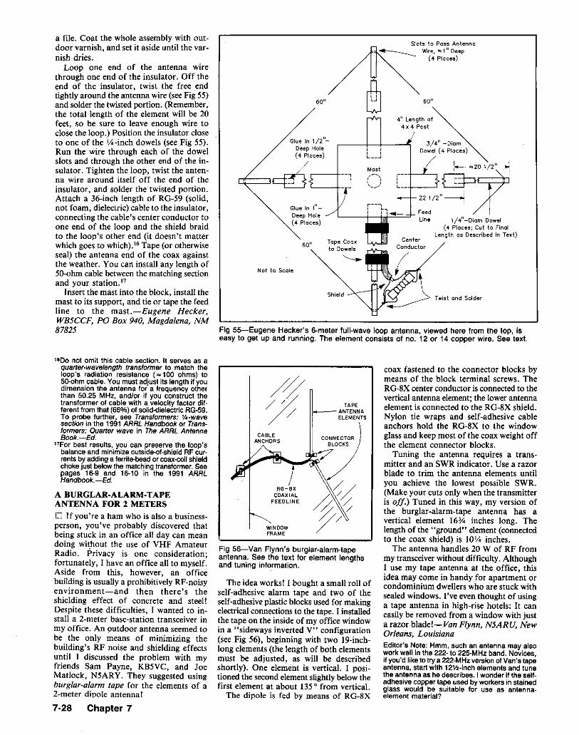
1/4"-Diom Dowel(4 Places; Cut to FInal
Length as Described in Text)
60"
4" Length of4x4Post
3/4" -cDfcmDowel (4 Places)
CenterConductor
Mast
Slots to Pass Antenne4--------... Wire, "" 1" Deep(4 Places)
r--,, ", "
, ,, ,L __ ...J
Shield
Tape Coaxto Dowels
Glue In 1"Deep Hole(4 Places)
60"
60"
Not to Scale
Glue In 1/2"Deep Hole(4 Pieces)
¢=~,--------j-
Fig 55-Eugene Hecker's 6-meter full-wave loop antenna. viewed here from. the top, Iseasy to get up and running. The element consists of no. 12 or 14 copper wire. See text.
a file. Coat the whole assembly with outdoor varnish, and set it aside until the varnish dries.
Loop one end of the antenna wirethrough one end of the insulator. Off theend of the insulator, twist the free endtightly around the antenna wire (see Fig 55)and solder the twisted portion. (Remember,the total length of the element will be 20feet, so be sure to leave enough wire toclose the loop.) Position the insulator closeto one of the lA-inch dowels (see Fig 55).Run the wire through each of the dowelslots and through the other end of the insulator. Tighten the loop, twist the antenna wire around itself off the end of theinsulator, and solder the twisted portion.Attach a 36-inch length of RG-59 (solid,not foam, dielectric) cable to the insulator,connecting the cable's center conductor toone end of the loop and the shield braidto the loop's other end (it doesn't matterwhich goes to which)." Tape (or otherwiseseal) the antenna end of the coax againstthe weather. You can install any length of50-ohm cable between the matching sectionand your station."
Insert the mast into the block, install themast to its support, and tie or tape the feedline to the mast.-Eugene Hecker,WB5CCF, PO Box 940, Magdalena, NM87825
16 00 not omit this cable section. It serves as aquarter-wavelength transformer to match theloop's radiation resistance C"" 100 ohms) toSO-ohm cable. You must adjust its length if youdimension the antenna for a frequency otherthan SO.2S MHz, and/or if you construct thetransformer of cable with a velocity factor different from that (66%) of solid-dielectric AG-59.To probe further, see Transformers: 1J4-wavesection in the 1991 ARRL Handbook or Transformers: Quarter wave in The ARRL AntennaBook.-Ed.
17For best results, you can preserve the loop'sbalance and minimize outside-of-shield AF currents by adding a ferrite-bead or coax-colt shieldchoke just below the matching transformer. Seepages 16-9 and 16-10 in the 1991 ARRLHandbook.-Ed.
A BURGLAR·ALARM-TAPEANTENNA FOR 2 METERS
o If you're a ham who is also a businessperson, you've probably discovered thatbeing stuck in an office all day can meandoing without the use of VHF AmateurRadio. Privacy is one consideration;fortunately, I have an office all to myself.Aside from this. however. an officebuilding is usually a prohibitively RF-noisyenvironment-and then there's theshielding effect of concrete and steel!Despite these difficulties, I wanted to install a 2-meter base-station transceiver inmy office. An outdoor antenna seemed tobe the only means of minimizing thebuilding's RF noise and shielding effectsuntil ] discussed the problem with myfriends Sam Payne, KB5VC. and JoeMatlock, N5ARY. They suggested usingburglar-alarm tape for the elements of a2-meter dipole antenna!
TAPEANTENNAELEMENTS
/RG-8X
COAXIALFEEOLINE
WINDOWFRAME
Fig 56-Van Flynn's burglar-alarm-tapeantenna. See the text for element lengthsand tuning information.
The idea works! I bought a small roll ofself-adhesive alarm tape and two of theself-adhesive plastic blocks used for makingelectrical connections to the tape. I installedthe tape on the inside of my office windowin a "sideways inverted V.. configuration(see Fig 56), beginning with two 19-inchlong elements (the length of both elementsmust be adjusted, as will be describedshortly). One element is vertical. I positioned the second element slightly below thefirst element at about 135 0 from vertical.
The dipole is fed by means of RG-8X
coax fastened to the connector blocks bymeans of the block terminal screws. TheRG-8X center conductor is connected to thevertical antenna element; the lower antennaelement is connected to the RG-8X shield.Nylon tie wraps and self-adhesive cableanchors hold the RG-8X to the windowglass and keep most of the coax weight offthe element connector blocks.
Tuning the antenna requires a transmitter and an SWR indicator. Use a razorblade to trim the antenna elements untilyou achieve the lowest possible SWR.(Make your cuts only when the transmitteris off.) Tuned in this way, my version ofthe burglar-alarm-tape antenna has avertical element 16314 inches long. Thelength of the "ground" element (connectedto the coax shield) is 10'/.1 inches.
The antenna handles 20 W of RF frommy transceiver without difficulty. AlthoughI use my tape antenna at the office. thisidea may come in handy for apartment orcondominium dwellers who are stuck withsealed windows. I've even thought of usinga tape antenna in high-rise hotels: It caneasily be removed from a window with justa razor bladeJ- Van Flynn, N5ARU, NewOrleans, LouisianaEditor's Note: Hmm, such an antenna may alsowork well In the 222- to 22S-MHzband. Novices,if you'd like to try a 222-MHzversionof Van's tapeantenna, start with 12V2-lnch elements and tunethe antenna as he describes. I wonder if the selfadhesive copper tape used by workers in stainedglass would be suitable for use as antennaelement material?
7-28 Chapter 7
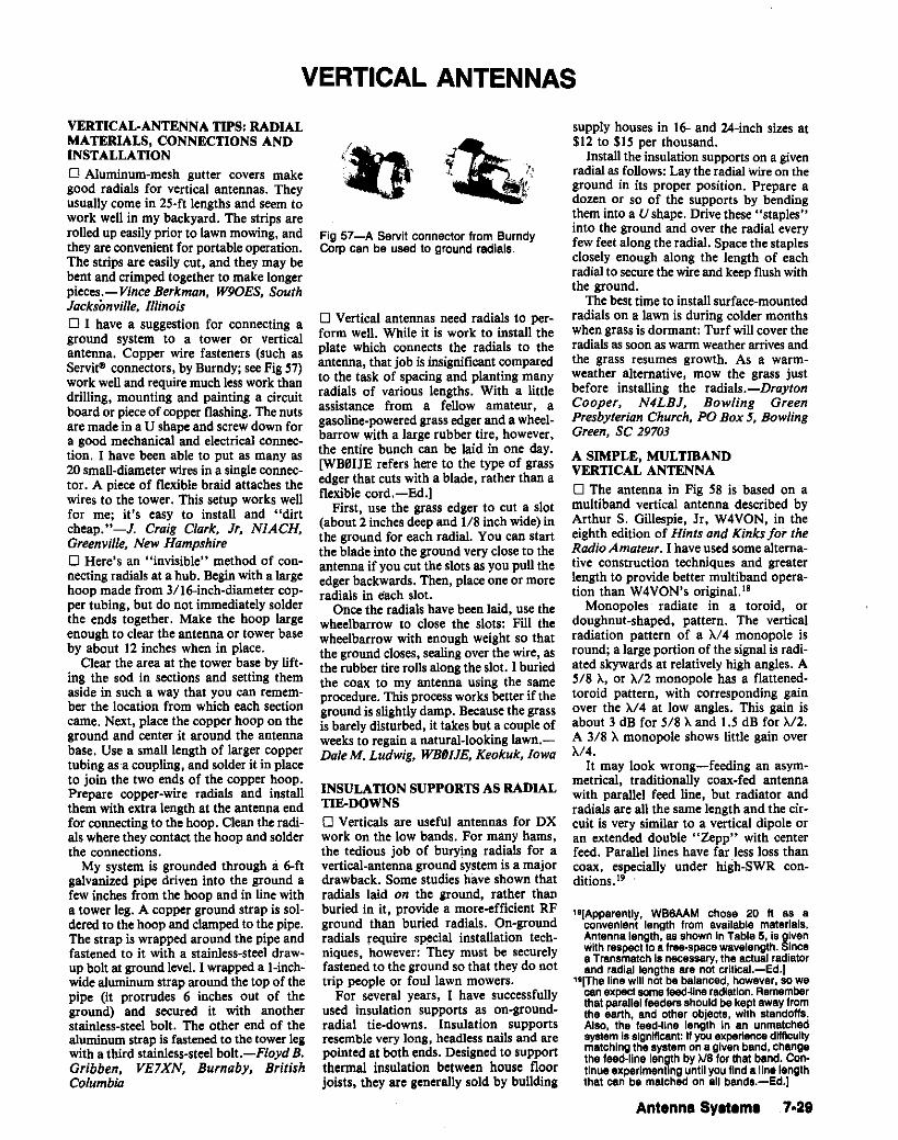
VERTICAL ANTENNAS
VERTICAL-ANTENNA TIPS: RADIALMATERIALS, CONNECTIONS ANDINSTALLATIONo Aluminum-mesh gutter covers makegood radials for vertical antennas. Theyusually come in 25-ft lengths and seem towork well in my backyard. The strips arerolled up easily prior to lawn mowing, andthey are convenient for portable operation.The strips are easily cut, and they may bebent and crimped together to make longerpieces.-Vince Berkman, W90ES, SouthJacksonville, Illinoiso I have a suggestion for connecting aground system to a tower or verticalantenna. Copper wire fasteners (such asServit~ connectors, by Burndy; see Fig 57)work well and require much less work thandrilling, mounting and painting a circuitboard or pieceof copper flashing. The nutsaremadein a U shapeand screw down fora good mechanical and electrical connection. I have been able to put as many as20 small-diameter wires in a singleconnector. A piece of flexible braid attaches thewires to the tower. This setup works wellfor me; it's easy to install and "dirtcheap."-J. Craig Ctark, Jr, NIACH,Greenville, New Hampshireo Here's an "invisible" method of connecting radials at a hub. Begin with a largehoop made from 3/16-inch-diameter copper tubing, but do not immediately solderthe ends together. Make the hoop largeenough to clearthe antennaor towerbaseby about 12 inches when in place.
Clear the area at the tower base by lifting the sod in sections and setting themaside in such a way that you can remember the location from which each sectioncame. Next, place the copper hoop on theground and center it around the antennabase. Use a small length of larger coppertubingasa coupling, and solderit in placeto join the two ends of the copper hoop.Prepare copper-wire radials and installthem with extra length at the antenna endfor connecting to the hoop. Clean the radials where they contact the hoop and solderthe connections.
My system is grounded through a 6·ftgalvanized pipe driven into the ground afew inches from the hoop and in line witha tower leg. A copper ground strap is soldered to the hoop and clamped to the pipe.The strap is wrapped around the pipe andfastened to it with a stainless-steel drawup bolt at ground level. I wrapped a f-inchwide aluminum strap around the top of thepipe (it protrudes 6 inches out of theground) and secured it with anotherstainless-steel bolt. The other end of thealuminum strap is fastened to the towerlegwith a third stainless-steel bolt.-Floyd B.Gribben, VE7XN, Burnaby, BritishColumbia
Fig 57-A Servit connector from BurndyCorp can be used to ground radials.
D Vertical antennas need radials to perform well. While it is work to install theplate which connects the radials to theantenna, thatjob is insignificant comparedto the task of spacing and planting manyradials of various lengths. With a littleassistance from a fellow amateur, agasoline-powered grass edger and a wheelbarrow with a large rubber tire, however,the entire bunch can be laid in one day.[WB0IJE refers here to the type of grassedger that cuts with a blade, rather than aflexible cord.-Ed.]
First, use the grass edger to cut a slot(about 2 inches deep and 1/8 inch wide) inthe ground for each radial. You can startthe blade into the ground very close to theantenna if you cut the slots as you pull theedgerbackwards. Then, placeone or moreradials in each slot.
Once the radials have been laid, use thewheelbarrow to close the slots: Fill thewheelbarrow with enough weight so thatthe ground closestsealingover the wire,asthe rubber tire rolls along the slot. I buriedthe coax to my antenna using the sameprocedure. This process worksbetterif theground is slightly damp. Because the grassis barely disturbed, it takes but a couple ofweeks to regaina natural-looking lawn.DaleM. Ludwig, WBfJIJE, Keokuk, Iowa
INSULATION SUPPORTS AS RADIALTIE-DOWNSo Verticals are useful antennas for DXwork on the low bands. For many hams,the tedious job of burying radials for avertical-antenna groundsystem is a majordrawback. Some studies have shown thatradials laid on the ground, rather thanburied in it, provide a more-efficient RFground than buried radials. On-groundradials require special installation techniques, however: They must be securelyfastened to the ground so that they do nottrip people or foul lawn mowers.
For several years, I have successfullyused insulation supports as on-groundradial tie-downs. Insulation supportsresemblevery long, headlessnails and arepointed at both ends. Designed to supportthermal insulation between house floorjoists, they are generally sold by building
supply houses in 16- and 24-inch sizes atSI2 to SIS per thousand.
Install the insulation supports on a givenradial as follows:Laythe radial wireon theground in its proper position. Prepare adozen or so of the supports by bendingthem into a U shape. Drivethese"staples'into the ground and over the radial everyfew feet along the radial. Space the staplesclosely enough along the length of eachradial to secure the wireand keep flush withthe ground.
The best timeto installsurface-mountedradialson a lawn is duringcolder monthswhengrassis dormant: Turfwill cover theradials as soon as warm weather arrives andthe grass resumes growth. As a warmweather alternative, mow the grass justbefore installing the radials.-DraytonCooper, N4LBJ, Bowling GreenPresbyterian Church, PO Box 5; BowlingGreen, SC 29703
A SIMPLE, MULTmANDVERTICAL ANTENNAo The antenna in Fig 58 is based on amultiband vertical antenna described byArthur S. Gillespie, Jr, W4VON, in theeighth edition of Hints and Kinks for theRadio Amateur. I haveused some alternative construction techniques and greaterlength to provide better multiband operation than W4VON's original."
Monopoles radiate in a toroid, ordoughnut-shaped, pattern. The verticalradiation pattern of a A/4 monopole isround;a largeportionof the signalis radiated skywards at relatively high angles. A5/8 A, or A/2 monopole has a flattenedtoroid pattern, with corresponding gainover the A/4 at low angles. This gain isabout 3 dB for 5/8 A and I.S dB for A/2.A 3/8 A monopole shows little gain overA/4.
It may look wrong-feeding an asymmetrical, traditionally coax-fed antennawith parallel feed line, but radiator andradials are all the same length and the circuit is very similar to a vertical dipole oran extended double "Zepp" with centerfeed. Parallel lines have far less loss thancoax, especially under high-SWR conditions.J?
11lApparently, WB6AAM chose 20 ft as aconvenient length from available materials.Antenna length, as shown In Table5, is givenwithrespect to a tree-space wavelength. Sincea Transmatch Is necessary, the actual radiatorand radial lengths are not critical.-Ed.)
11l(The linewill notbe balanced, however, sowecan expect some feed-tlne radiation. Rememberthatparallel feeders should be keptawayfromthe earth, and other objects, with standoffs.Also, the feed-line length In an unmatchedsystem issignificant: If you experience difficultymatching thesystem ona given band,changethe foed-line length by>.18 for that band.Con.tlnueexperimenting until you find aUn,lengththat can be matched on all bands.-Ed.)
Antenna Sy.tem. 7·29

20 FT
PARALLEL-,~Iti:n:o:r= LINE TO-- TRANSMATCH
20 FT RADIALS(FOUR MINIMUM)
Fig 58-WB8AAM's multiband verticalmonopole antenna. Estimated gain~ forvarious amateur bands are shown InTable 5.
SMALL TV ANTENNA
I2- 3 FOOT
PLASTIC TUBe:
GUY WIRESFAKE TVRIBBON
20 FT TV MAST
STANDOFFS(TYP)
TWIN~ LEADFEEO LINE
TOTRANSMATCH
Fig 59-WB6AAM's antenna can becamouflaged easily as a commercial-TVinstallation. (For clarity, only one set of guywires is lthrstrated.) (One could eliminatethe top plastic tube and bond the TVantenna to the mast top as capacitiveloading. This would make the antennaelectrical length slightly longer than20 ft.-Ed.]
The radiator can be any conductor: flagpole, round or square aluminum stock,wire and standoffs on a dry wooden pole,or Tv-mast sections to name a few. A military set with mast sections, whip sections,insulator, base and guys would be a goodfield antenna.
Someone who lives where only TVantennas are allowed could try this idea:Use two lO~ft sections of TV mast and adda plastic insulating section (of a similarcolor) with a small TV antenna on the top.
7-30 Chapter 7
Table 5Estimated Performance ofWB6AAM's Antennat .
Band Antenna Estimated gainLength over JJ4
10 m 0.58 X 3 dB12. m 0.51 X 2 dB15 m 0.43 X 1.5 dB17 m 0.36 X 1 dB2.0 m 0.28 X 0.5 dB3D m 0.20 X4Dm 0.15 X80 m 0.08 X
t Galn shown is with respect to a >J4 verticalmonopole over a similar reflecting surface.
To add realism, add some TV standoff insulators and fake twinlead. (Remove thewire from the ribbon cable so that it doesnot interact with the antenna.) The radialscan be thin wire or TV ribbon, close to theroof on standoffs. (Short each end of theTV ribbon-Fig 59.)
My version of W4VON's antenna is 5/8A on 10 meters as I prefer the 10, 12 and15~meter bands. The design could bechanged for 5/8 A on some other band.Remember, however, that the take-offangle steepens quickly as antenna lengthexceeds 3/4 A. As the length increases toA, the vertical radiation pattern becomesmore complex-resembling a cloverleaf,rather than a toroid. Multiple lobes ofenergy appear skywards as the length increases, with only minor lobes near thehorizon. A lO-meter OSCAR user mighttake advantage of such a pattern, but terrestrial contacts won't be very strong.James G. Coote, WB6AAM, Los Angeles,California
PUTTING THE BUTTERNUTVERTICAL ANTENNA ON160 METERS
o My 160~meter antenna is a ButternutHF2V equipped with the optional160-meter base coil. Considering that thisantenna is only 32 feet long, it does a goodjob. Its bandwidth on 160 is 10 kHz or sowithout top loading. In fact, life on 160with the HF2V is difficult for me only whenI want to move around in the band:Readjusting the antenna is laborious.
My attempt to solve this problem was toput taps on the 160~meter base coil. I wassatisfied with this until the weather turnedbad. (Working at the antenna base in thefreezing rain is unpleasant enough to getthe old gray matter working on a betterway!)
Butternut's optional 160-meter loadingcoil kit consists of a large inductor, twohigh-voltage 200-pF capacitors andmounting hardware. The two capacitors areused in parallel with the 16O-meter coil toresonate the antenna in the 160-meterband.It occurred to me that easy remote tuningcould be mine if I replaced one of the
2OO-pF fixed capacitors with a motor drivenvariable unit-to be controlled from thecomfort of my shack, of course!
I calculated the inductance of the160-meter coil as roughly 12.8 pH. Furthercalculations revealed that a coil of thisvalue would require 550 pF to resonate at1.9 MHz-more capacitance than thatafforded by the paralleled 200-pF capacitors. Clearly, the antenna element addsenough inductance and capacitance to thecircuit to bring the system down to its correct frequency. I decided to treat theantenna's effect as purely capacitive in calculating the value of my variable "QSYcapacitor." I determined that placing a 150to-250-pF variable in parallel with one ofButternut's 200-pF add-on capacitorswould allow me to adjust the antenna'sresonant frequency across the entire160~meter band.
Finding a suitable variable capacitor wasthe next problem. I located a suitablecapacitor in an electronics surplus store.Problem, though: Under test, thecapacitor's 0.025-inch spacing could notwithstand the voltage across the 160-metertuned circuit. I increased its spacing to0.05 inch by removing every other rotorplate and maintained the proper rotor-tostator spacing by installing two rotor platesback-to-back wherever one was needed. Toobtain the 150-pF minimum capacitancecalled for in my calculations, I rotated threeof the rotor plates 180 0 relative to theothers and paralleled the variable with a50-pF, 3000-Vmica capacitor. When threeplates are fully meshed with the stator, thiscombination unit provides 150 pF; turningthe shaft 180 0 meshes four plates with thestator and increases the total capacitanceto 250 pF. I tested the QSY capacitor bysubstituting it for one of Butternut's 200-pFunits. It worked great!
Next, I found a 120 V ac, 1 rlmin timermotor to turn the capacitor shaft. To supply power to the motor, I decided to usetwo 120- to 12.6-V transformers back toback-one in the shack (step down) and theother at the antenna base (step up). Themotor is coupled to the capacitor by meansof a l-inch piece of vinyl tubing cut froma fish tank suction cleaner. I mounted theQSY capacitor, motor and step-up transformer in a plastic lunch box and installedthe box at the base of the antenna. Toprotect the components from the weather.I sealed the lunch box with caulking.
The QSY capacitor allows me to tune theantenna for a 1:I SWR anywhere in the160-meter band. Installation of thecapacitor also had a positive effect on theSWR bandwidth at 40 and 80 meters: Igained 56 kHz at 80 and 84 kHz at 40.
Operating with the modified Butternutvertical is a pleasure. QSY on 160 isaccomplished as follows. First, I determinethe approximate capacitor setting byapplying less than 1 W to the antenna andwatching the SWR meter as the capacitoris tuned. As the capacitor approaches the
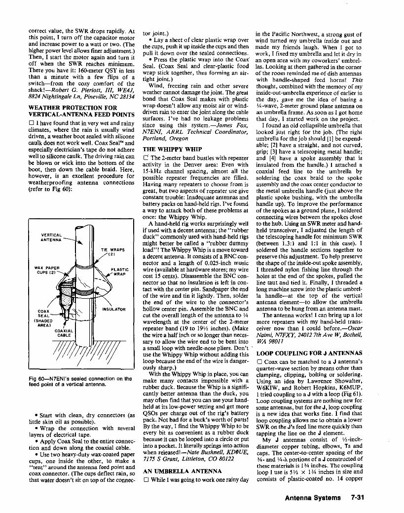
in the Pacific Northwest. a strong gust ofwind turned my umbrella inside out andmade my friends laugh. When I got towork, I fixed my umbrella and let it dry inan open area with my coworkers' umbrellas. Looking at them gathered in the cornerof the room reminded me of dish antennaswith handle-shaped feed horns! Thisthought, combined with the memory of myinside-aut-umbrella experience of earlier inthe day, gave me the idea of basing aY4-wave, z-meter ground plane antenna onan umbrella frame. As soon as I got homethat day, I started work on the project.
1 found an oid collapsible umbrella thatiooked just right for the job. (The rightumbrella for the job should [I] be expendable; [2] have a straight. and not curved,grip; [3] have a telescoping metal handle;and [4] have a spoke assembly that isinsulated from the handle.) I attached acoaxial feed line to the umbrella bysoldering the coax braid to the spokeassembly and the coax center conductor tothe metal umbrella handle (just above theplastic spoke bushing, with the umbrellahandle up). To improve the performanceof the spokes as a ground plane, I solderedconnecting wires between the spokes closeto the hub. Using an SWR meter and handheld transceiver, 1 adjusted the length ofthe telescoping handle for minimum SWR(between 1.3:1 and 1:1 in this case). 1soidered the handle sections together topreserve this adjustment. To help preservethe shape of the inside-out spoke assembly,1 threaded nylon fishing line through theholes at the end of the spokes, pulled theline taut and tied it. Finally. I threaded along machine screw into the plastic umbrella handle-at the top of the verticalantenna element-to allow the umbrellaantenna to be hung from an antenna mast.
The antenna works! I can bring up a lotmore repeaters with my hand-held transceiver now than I could before.-OscarNaimi, NlFXY, 240127thAve W, Bothell,WA 98011
LOOP COUPLING FOR J ANTENNAS
o Coax can be matched to a J antenna'squarter-wave section by means other thanclamping, clipping, bolting or soldering.Using an idea by Lawrence Showalter,W6KIW, and Robert Hopkins, K6MUP,1 tried coupling to a J with a loop (Fig 61).Loop coupling systems are nothing new forsome antennas, but for the J, loop couplingis a new idea that works fine. I find thatloop coupling allows me to obtain a lowerSWR on the J's feed line more quickly thantapping the line on the J element.
My J antennas consist of Y2-inchdiameter copper tubing. elbows, Ts andcaps. The center-to-center spacing of the~- and Y4-}.. portions of a J constructed ofthese materials is 13/4 inches. The couplingloop I use is 5 Y2 X 1~ inches in size andconsists of plastic-coated no. 14 copper
tor joint.)• Lay a sheet of clear plastic wrap over
the cups, push it up inside the cups and thenpull it down over the sealed connections.
• Press the plastic wrap into the Coax'Seal. (Coax Seal and clear-plastic foodwrap stick together, thus forming an airtight joint.}
Wind, freezing rain and other severeweather cannot damage the joint. The greatbond that Coax Seal makes with plasticwrap doesn't allow any moist air or winddriven rain to enter the joint along the cablesurfaces. I've had no leakage problemssince using this system.-James Fox,N7ENI, ARRL Technical Coordinator,Portland, Oregon
THE WHIPPY WHIP
o The 2-meter band bustles with repeateractivity in the Denver area: Even withIS-kHz channel spacing, almost all thepossible repeater frequencies are filled.Having many repeaters to choose from isgreat. but two aspects of repeater use giveconstant trouble: Inadequate antennas andbattery packs on hand-heid rigs. I've founda way to attack both of these problems atonce: the Whippy Whip.
A hand-held rig works surprisingly wellif used with a decent antenna; the "rubberduck" commonly used with hand-held rigsmight better be called a "rubber dummyload"! The Whippy Whip is a move towarda decent antenna. It consists of a BNC connector and a length of O.025-inch musicwire (available at hardware stores; my wirecost IS cents). Disassemble the BNC connector so that no insulation is left in contact with the center pin. Sandpaper the endof the wire and tin it lightly. Then, solderthe end of the wire to the connector'shollow center pin. Assemble the BNC andcut the overall length of the antenna to Y4wavelength at the center of the 2-meterrepeater band (19 to 19\1, inches). (Makethe wire a half inch or so longer than necessary to allow the wire end to be bent intoa small loop with needle-nose pliers. Don'tnse the Whippy Whip without adding thisloop because the end of the wire is dangerously sharp.)
With the Whippy Whip in place, you canmake many contacts impossible with arubber duck. Because the Whip is a significantly better antenna than the duck, youmay often find that you can use your handheld at its low-power setting and get moreQSOs per charge out of the rig's batterypack. Not bad for a buck's worth of parts!By the way, 1 find the Whippy Whip to beevery bit as convenient as a rubber duckbecause it can be looped into a circle or putinto a pocket. It literally springs into actionwhen released I-Nate Bushnell, KDDUE,7175 S Grant, Littleton, CO 80122
AN UMBRELLA ANTENNA
o While 1was going to work one rainy day
PLASTICWRAP
INSULATOR
TIE WRAPS(2)
WAX PAPERCUPS (21
• Start with clean. dry connectors (aslittle skin oil as possible).
• Wrap the connection with severallayers of electrical tape.
• Apply Coax Seal to the entire connection and down along the coaxial cable.
• Use two heavy-duty wax-coated papercups, one inside the other, to make a"tent" around the antenna feed point andcoax connector. (The cups deflect rain. sothat water doesn't sit on top of the connec-
correct value. the SWR drops rapidly. Atthis point, I turn off the capacitor motorand increase power to a watt or two. (Thehigher power level allows finer adjustment.)Then, I start the motor again and turn itoff when the SWR reaches minimum.There you have it: 160-meter QSY in lessthan a minute with a few flips of aswitch-from the cozy comfort of theshackl-Roberr G. Pierlott, 1I1, WE4J,8824 Nightingale Ln, Pineville, NC 28134
WEATHER PROTECTION FORVERTICAL·ANTENNA FEED POINTS
o I have found that in very wet and rainyclimates, where the rain is usually winddriven. a weather boot sealed with siliconecaulk does not work well. Coax Seal" andespecially electrician's tape do not adherewell to silicone caulk. The driving rain canbe blown or wick into the bottom of theboot. then down the cable braid. Here,however. is an excellent procedure forweatherproofing antenna connections(refer to Fig 60):
VERTICALANTENNA
Fig 6O-N7ENI's sealed connection on thefeed point of a vertical antenna.
Antenna Systems 7·31

(not to scale)
Plastic-CoatedNo. 14 Wire
Fig 61-Henry Davis feeds his VHF J antennaswith the loop coupling system shown here. Seethe text for how to position and mount the loop
1-3/4" for minimum SWR.
rrr'C::;:=:;:t~l:-::: Initial Spoce.3/8"
J Element
Plastic-CoatedConnections
Coax to station
7-32 Chapter 7
wire. Connect one end of the loop to thecoax center conductor and the other endof the loop to the coax shield. Be sure theloop ends don't touch where they connectto the coax, and coat the connections wellwith liquid plastic. (Plastic compounds intended for dip-coating tool handles workfine.) Position the loop flat against the J'spiping, with the loop bottom about 3/8inch from the inside bottom of the crookof the J. Temporarily tape the loop to theJ element.
Adjusting the loop for minimum SWRis simple: Move the loop up or down fromits initial position until you find the pointof minimum feed-line SWR. Once you'vefound this point, tape the loop as closelyto the J's copper pipe as possible. Spacebetween the coupling loop and the Jelement raises the SWR.-Henry Davis,W6DTV, 7822 Washington Ave, Sebastopol,CA 95472
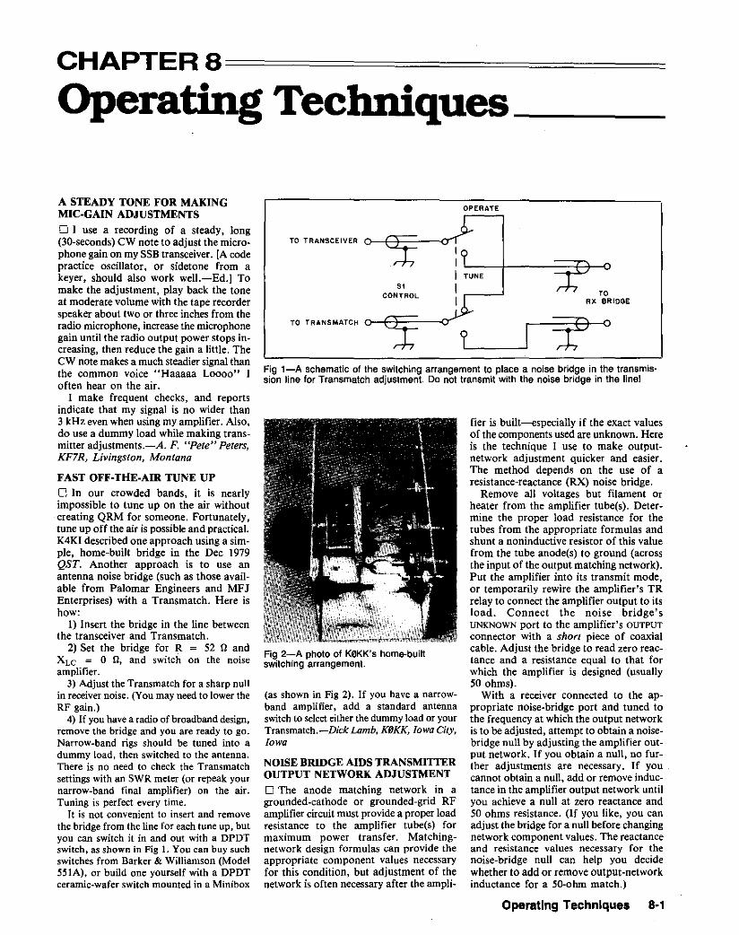
CHAPTER 8============
Operating Techniques _
OPERATE
TORX BRIDGE
fier is built-especially if the exact valuesof the components used are unknown. Hereis the technique I use to make outputnetwork adjustment quicker and easier.The method depends on the use of aresistance-reactance (RX) noise bridge.
Remove all voltages but filament Orheater from the amplifier tube(s). Determine the proper load resistance for thetubes from the appropriate formulas andshunt a noninductive resistor of this valuefrom the tube anode(s) to ground (acrossthe input of the output matching network).Put the amplifier into its transmit mode,or temporarily rewire the amplifier's TRrelay to connect the amplifier output to itsload. Connect the noise bridge'sUNKNOWN port to the amplifier's OUTPUT
connector with a short piece of coaxialcable. Adjust the bridge to read zero reactance and a resistance equal to that forwhich the amplifier is designed (usually50 ohms).
With a receiver connected to the appropriate noise-bridge port and tuned tothe frequency at which the output networkis to beadjusted, attempt to obtain a noisebridge null by adjusting the amplifier output network. If you obtain a null, no further adjustments are necessary. If youcannot obtain a null. add or remove inductance in the amplifier output network untilyou achieve a null at zero reactance and50 ohms resistance. (If you like. you canadjust the bridge for a null before changingnetwork component values. The reactanceand resistance values necessary for thenoise-bridge null can help you decidewhether to add or remove output-networkinductance for a 50-ohm match.)
TUNE
51CONTROL
TO TRANS MATCH
(as shown in Fig 2). If you have a narrowband amplifier, add a standard antennaswitchto selecteither the dummyload or yourTransmatch.-Dick Lamb. KfJKK. Iowa City.Iowa
Fig 1-A schematic of the switching arrangement to place a noise bridge in the transmission line for Transmatch adjustment. Do not transmit with the noise bridge in the line!
TO TRANSCEIVER
NOISE BRIDGE AIDS TRANSMITTEROUTPUT NETWORK ADJUSTMENT
o The anode matching network in agrounded-cathode or grounded-grid RFamplifier circuit must provide a proper loadresistance to the amplifier tube(s) formaximum power transfer. Matchingnetwork design formulas can provide theappropriate component values necessaryfor this condition, but adjustment of thenetwork is often necessary after the ampli-
Fig 2-A photo of K0KK's home-builtswitching arrangement.
FAST OFF·THE·AIR TUNE UPo In our crowded bands, it is nearlyimpossible to tune up on the air withoutcreating QRM for someone. Fortunately,tune up off the air is possible and practical.K4KI described one approach using a simple, home-built bridge in the Dec 1979QST. Another approach is to use anantenna noise bridge (such as those available from Palomar Engineers and MFJEnterprises) with a Transmatch. Here ishow:
1) Insert the bridge in the line betweenthe transceiver and Transmatch.
2) Set the bridge for R = 52 II andXL C = 0 n, and switch on the noiseamplifier.
3) Adjust the Transmatch for a sharp nullin receivernoise. (You may need to lower theRF gain.)
4) If you havea radio of broadband design,remove the bridge and you are ready to go.Narrow-band rigs should be tuned into adummy load, then switched to the antenna.There is no need to check the Transmatchsettings with an SWR meter (or repeak yournarrow-band final amplifier) on the air.Tuning is perfect every time.
It is not convenient to insert and removethe bridge from the line for each tune up, butyou can switch it in and out with a DPDTswitch, as shown in Fig 1. You can buy suchswitches from Barker & Williamson (Model551A), or build one yourself with a DPDTceramic-wafer switch mounted in a Minibox
A STEADY TONE FOR MAKINGMIC·GAIN ADJUSTMENTS
o ] use a recording of a steady. long(30-seconds) CW note to adjust the microphone gain on my SSB transceiver. [A codepractice oscillator. or sidetone from akeyer, should also work well.-Ed.] Tomake the adjustment, play back the toneat moderate volume with the tape recorderspeaker about two or three inches from theradio microphone, increase the microphonegain until the radio output power stops increasing, then reduce the gain a little. TheCW note makes a much steadier signal thanthe common voice "Haaaaa Loooo" Ioften hear on the air.
I make frequent checks. and reportsindicate that my signal is no wider than3 kHz even when using my amplifier. Also.do use a dummy load while making transmitter adjustments.-A. F. "Pete" Peters,KF7R, Livingston, Montana
Operating Techniques 8·1
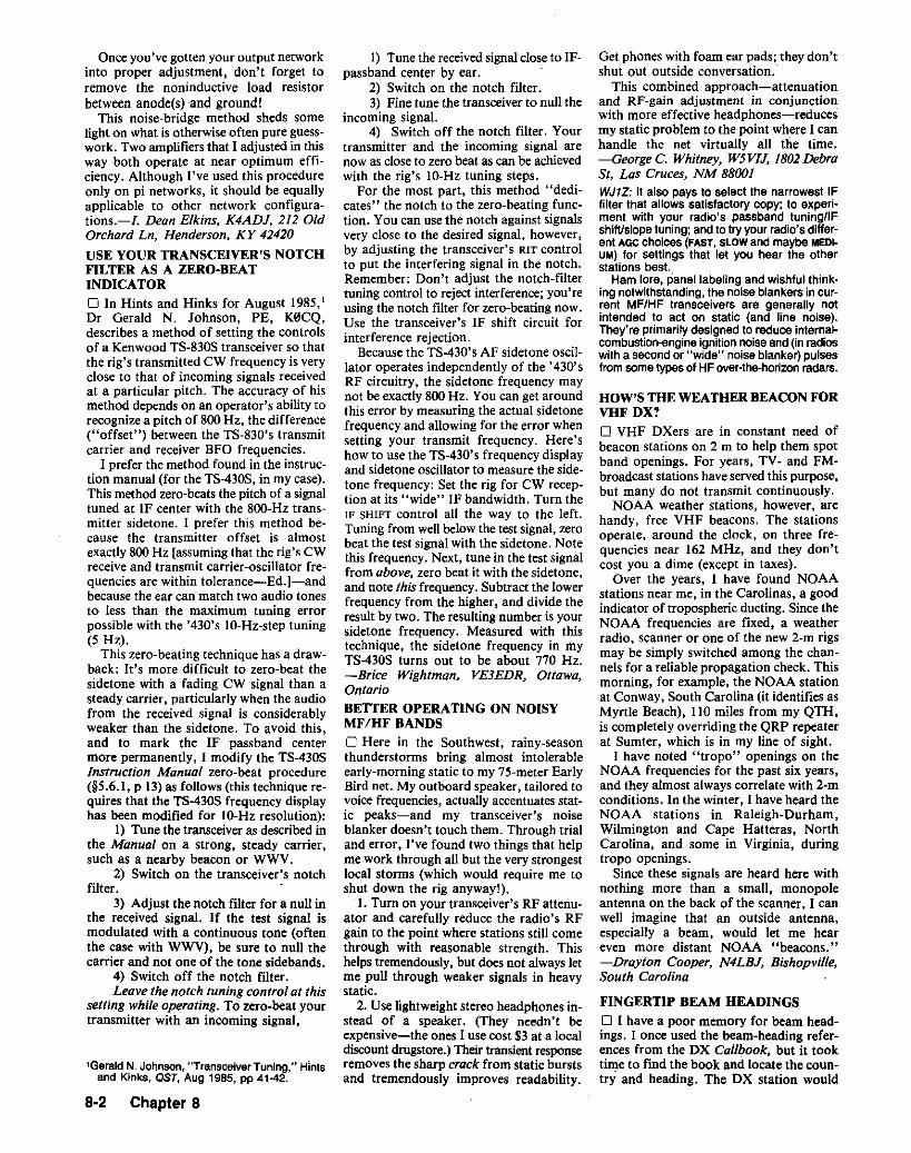
Once you've gotten your output networkinto proper adjustment, don't forget toremove the noninductive load resistorbetween anode(s) and ground!
This noise-bridge method sheds somelight on what is otherwise often pure guesswork. Two amplifiers that I adjusted in thisway both operate at near optimum efficiency. Although I've used this procedureonly on pi networks, it should be equallyapplicable to other network configurations.-I. Dean Elkins, K4ADJ, 212 OldOrchard Ln, Henderson, KY 42420
USE YOUR TRANSCEIVER'S NOTCHFILTER AS A ZERO-BEATINDICATORo In Hints and Hinks for August 1985,I
Dr Gerald N. Johnson, PE, K0CQ,describes a method of setting the controlsof a Kenwood TS-830S transceiver so thatthe rig's transmitted CW frequency is veryclose to that of incoming signals receivedat a particular pitch. The accuracy of hismethod depends on an operator's ability torecognize a pitch of 800 Hz, the difference("offset") between the TS-830's transmitcarrier and receiver BFO frequencies.
I prefer the method found in the instruction manual (for the TS-430S, in my case).This method zero-beats the pitch of a signaltuned at IF center with the 8oo-Hz transmitter sidetone. I prefer this method because the transmitter offset is almostexactly 800 Hz [assuming that the rig's CWreceive and transmit carrier-oscillator frequencies are within tolerance-Ed.]-andbecause the ear can match two audio tonesto less than the maximum tuning errorpossible with the '430's lO-Hz-step tuning(5 Hz).
This zero-beating technique has a drawback: It's more difficult to zero-beat thesidetone with a fading CW signal than asteady carrier, particularly when the audiofrom the received signal is considerablyweaker than the sidetone. To avoid this,and to mark the IF passband centermore permanently, I modify the TS-430SInstruction Manual zero-beat procedure(§5.6.1, p 13)as follows (this technique requires that the TS-430S frequency displayhas been modified for lO-Hz resolution):
1) Tune the transceiver as described inthe Manual on a strong, steady carrier,such as a nearby beacon or WWV.
2) Switch on the transceiver's notchfilter.
3) Adjust the notch filter for a null inthe received signal. If the test signal ismodulated with a continuous tone (oftenthe case with WWV), be sure to null thecarrier and not one of the tone sidebands.
4) Switch off the notch filter.Leave the notch tuning control at this
setting while operating. To zero-beat yourtransmitter with an incoming signal,
1Gerald N. Johnson."TransceiverTuning," Hintsand Kinks, QST, Aug 1985, PP 41-42.
8·2 Chapter 8
1) Tune the receivedsignal closeto IFpassband center by ear.
2) Switch on the notch filter.3) Fine tune the transceiver to null the
incoming signal.4) Switch off the notch filter. Your
transmitter and the incoming signal arenow as close to zero beat as can be achievedwith the rig's lO-Hz tuning steps.
For the most part, this method "dedicates" the notch to the zero-beating function. You can use the notch against signalsvery close to the desired signal, however,by adjusting the transceiver's RIT controlto put the interfering signal in the notch.Remember: Don't adjust the notch-filtertuning control to reject interference; you'reusing the notch filter for zero-beating now.Use the transceiver's IF shift circuit forinterference rejection.
Because the TS-430's AF sidetone oscillator operates independently of the '430'sRF circuitry, the sidetone frequency maynot be exactly 800 Hz. You can get aroundthis error by measuring the actual sidetonefrequency and allowing for the error whensetting your transmit frequency. Here'show to use the TS-430's frequency displayand sidetone oscillator to measure the sidetone frequency: Set the rig for CW reception at its "wide" IF bandwidth. Turn theIF SHIFT control all the way to the left.Tuning from wellbelow the test signal, zerobeat the test signal with the sidetone. Notethis frequency. Next, tune in the test signalfrom above, zero beat it with the sidetone,and note this frequency. Subtract the lowerfrequency from the higher, and divide theresult by two. The resulting number is yoursidetone frequency. Measured with thistechnique, the sidetone frequency in myTS-430S turns out to be about 770 Hz.-Brice Wightman, VE3EDR, Ottawa,OntarioBETTER OPERATING ON NOISYMF/HF BANDS
o Here in the Southwest, rainy-seasonthunderstorms bring almost intolerableearly-morning static to my 75-meter EarlyBird net. My outboard speaker, tailored tovoice frequencies, actually accentuates static peaks-and my transceiver's noiseblanker doesn't touch them. Through trialand error, I've found two things that helpme work through all but the very strongestlocal storms (which would require me toshut down the rig anyway!).
1. Turn on your transceiver's RF attenuator and carefully reduce the radio's RFgain to the point where stations still comethrough with reasonable strength. Thishelps tremendously, but does not always letme pull through weaker signals in heavystatic.
2. Use lightweight stereo headphones instead of a speaker. (They needn't beexpensive-the ones I use cost $3 at a localdiscount drugstore.) Their transient responseremoves the sharp crack from static burstsand tremendously improves readability.
Get phones with foam ear pads; they don'tshut out outside conversation.
This combined approach-attenuationand RF-gain adjustment in conjunctionwith more effective headphones-reducesmy static problem to the point where I canhandle the net virtually all the time.-George C. Whitney, W5VIJ, 1802Debrast. Las Cruces, NM 88001WJ1Z: It also pays to select the narrowest IFfilter that allows satisfactory copy; to experiment with your radio's passband tuning/IFshift/slope tuning; and to try your radio's different AGC choices (FAST. SLOW and maybe MEDI·UM) for settings that let you hear the otherstations best.
Ham lore, panel labeling and wishful thinking notwithstanding, the noise blankers in current MF/HF transceivers are generally notintended to act on static (and line noise).They're primarily designed to reduce internalcombustion-engine ignition noise and (in radioswith a second or "wide" noise blanker) pulsesfrom some types of HF over-the-honzon radars.
HOW'S THE WEATHER BEACON FORVHF DX?o VHF DXers are in constant need ofbeacon stations on 2 m to help them spotband openings. For years, TV- and FMbroadcast stations have served this purpose,but many do not transmit continuously.
NOAA weather stations, however, arehandy, free VHF beacons. The stationsoperate, around the clock, on three frequencies near 162 MHz, and they don'tcost you a dime (except in taxes).
Over the years, I have found NOAAstations near me, in the Carolinas, a goodindicator of tropospheric ducting. Since theNOAA frequencies are fixed, a weatherradio, scanner or one of the new 2-m rigsmay be simply switched among the channels for a reliable propagation check. Thismorning, for example, the NOAA stationat Conway, South Carolina (it identifies asMyrtle Beach), 110 miles from my QTH,is completely overriding the QRP repeaterat Sumter, which is in my line of sight.
I have noted "tropo" openings on theNOAA frequencies for the past six years,and they almost always correlate with 2-mconditions. In the winter, I have heard theNOAA stations in Raleigh-Durham,Wilmington and Cape Hatteras, NorthCarolina, and some in Virginia, duringtropo openings.
Since these signals are heard here withnothing more than a small, monopoleantenna on the back of the scanner, I canwell imagine that an outside antenna,especially a beam, would let me heareven more distant NOAA "beacons."-s-Drayton Cooper, N4LBJ, Bishopville,South Carolina
FINGERTIP BEAM HEADINGS
o I have a poor memory for beam headings. lance used the beam-heading references from the DX Cal/book, but it tooktime to find the book and locate the country and heading. The DX station would

usually contact someone elseor change frequency before I found the heading, and Iwould lose him. My solution is a Desk TopAutomatic Directory (model 43-105;$24.95) from Radio Shack@ . This deviceis intended for fast location of telephonenumbers. 1 use it to find beam headingsrather than phone numbers. If I hear a TIcall sign, I simply push the button lettered"T" and see that TI is Costa Rica and thebeam heading is 199°. It's both speedy andefficient.
The directory is powered by two C-sizebatteries. It has a keyboard consisting of15buttons labeled from A to Z. It containsabout 40 index cards, which can be selected by pressing the appropriate button. Ilisted the countries alphabetically according to their call-sign prefixes and have over340 on the index cards. Call signs withnumbered prefixes are listed under "MN"and "QR."-George R. Golodich, K20EK,West Haverstraw, New YorkD Here is a way to have beam headingsand international prefixes instantly available. With this simplegadget, you can haveyour antenna pointed at that rare OX station before he finishes his CQ call.
Next time you go grocery shopping, buya large can of tomato juice. I found a46-ounce can that is 7 inches tall and 4Y2inches in diameter, with no dents-justright!
1) Remove the label, empty and rinse thecan through two small holes in one end.
2) Drill a hole in the exact center of eachend to snugly fit a pencil-size rod aboutfour inches longer than the can. (A 2-inchextension at each end serves as an axle forthe rotating drum.) Apply a little solder orepoxy to the axle and can ends to hold therod in place.
3) Remove the pageof International Radio
Amateur Prefixes from the Callback, andwrite the beam heading for each countrynext to the prefix. Trim the page marginsto fit the drum, and secure the page to thedrum with tape.
4) Make a rack of wood or metal to holdthe drum, and place the assemblynear yourrotator controller.
With the completed beam-heading drumyou can have your beam set "right on" andready to answer when that DX station signs"over!'-Mal Tindall, KA8GOB, Sarasota,Florida
PENCIL CONTROL FORCONTESTERS
D In a CW contest, it is a terrible nuisanceto keep track of your pencil, and you mayhave wished there was some simple wayto eliminate that constant search. There is:Wear the pencil on your middle finger,cradled next to your forefinger. Attach thepencil to your middle finger with two rubber bands positioned between the knuckleand first joint, with the pencil point-somewhat back of the middle finger tip. Towrite, curl your forefinger over the penciland draw it down to be gripped betweenthe forefinger and thumb on one side andthe middle finger on the other side. (That'snot how you were taught to hold a pencil,but penmanship is good enough for printing a log sheet.) After writing, curl yourforefinger under the pencil and the rubberbands to lift it out of your way. Voila!Pencils that are over five inches long don'tseem to balance well.- W. A. "Spud"Monahan. K6KH. Manhattan Beach,California
KEEPING TRACK OF AWARDENDORSEMENTS
D Some operating awards can be endorsed
foradditional submissionsbeyond the basicqualification level. Keeping track ofprogress up the endorsement ladder requires good record keeping. You can usethe same award-record sheets again andagain if you use a colored pen (I use red)to enter QSO data on the record sheet.When you have accumulated enoughentries to qualify for the basicaward, makea black-and-white photocopy of the recordsheets for yourself and send the originalsto the award administrator.
Use the photocopied sheets to track yourendorsement progress without confusion.The entries you made in color on theoriginal record sheets appear in black onthe photocopy. Record your endorsementdata in color on the photocopy, and you'llhave no trouble distinguishing records ofendorsement QSOs (colored ink) from datapertaining to the basic award (black ink).
I devised this scheme to aid me inworking toward Japan Amateur RadioLeague awards. JARL's Japan CenturyCities (JCC) and JCG (Japan CenturyGuns)? awards, for example, haveendorsement increments of 100, beginningat 2oo. With 641 Japanese Century Citiesand 569 Japanese Century Guns, I'd gocrazy without an easy means of distinguishing records of the first hundredQSOs from records of the second hundred,and so on. This technique helps me keepmy records straight.-Jack Wichels,W7YF. Edmonds, Washington
2Japan has, as administrative districts,47 prefectures. These are divided into cities,towns and villages. The gun, which is not anadministrative district, is a regional congregation of towns and Villages. See The ARRLOperating Manual, third edition, for details onJARL awards.-Ed.
Operating Techniques B·3

I
I
I
I
I
I
I
I
I
I
I
I
I
I
I
I
I
I
I
I
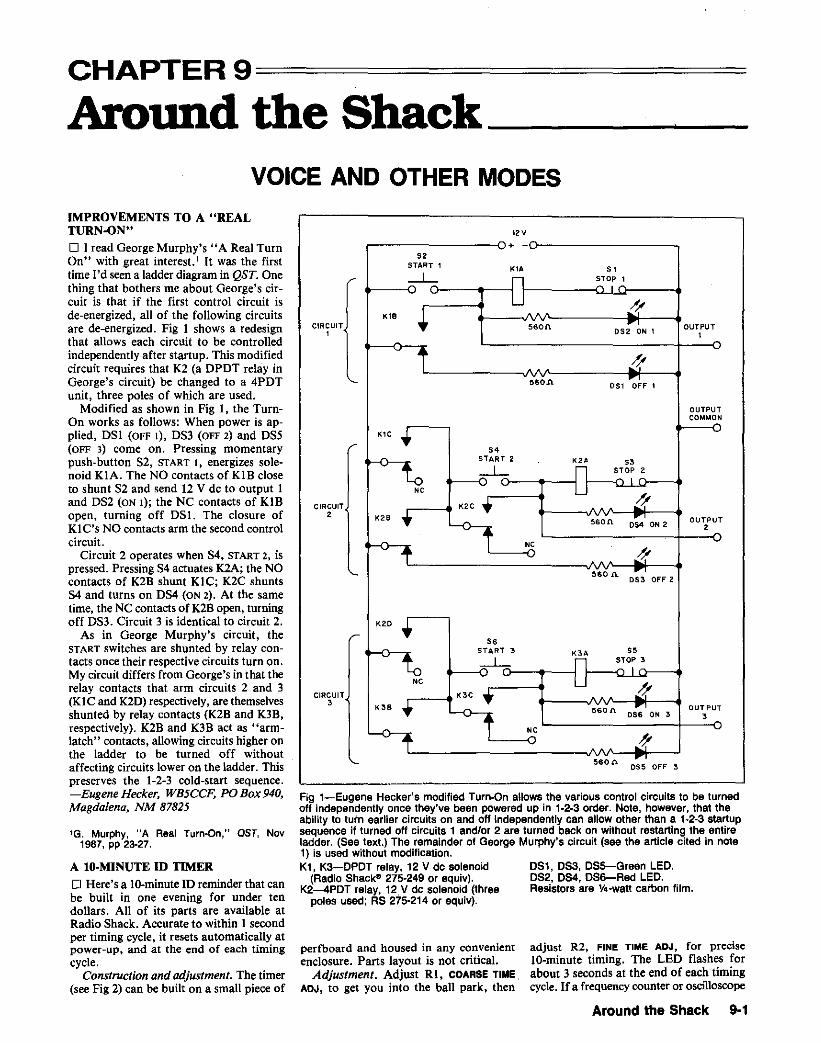
CHAPTER 9=============
Around the Shack _VOICE AND OTHER MODES
I2V
Fig 1-Eugene Hecker's modified Turn-On allows the various control circuits to be turnedoff independently once they've been powered up in 1·2·3 order. Note, however, that theability to turn earlier circuits on and off Independently can allow other than a 1-2-3 startupsequence if turned off circuits 1 and/or 2 are turned back on without restarting the entireladder. (See text.) The remainder of George Murphy's circuit (see the article cited in note1) is used without modification.K1, K3-0POT relay. 12 V de solenoid OS1, OS3, OS5-Green LED.
(Radio Shac~ 275-249 or equiv). OS2. 0S4. OS6-Red LED.K2-4PDT relay, 12V de solenoid (three Resistors are Y4-watt carbon film.
pole. used; RS 275·214 or equiv).
perfboard and housed in any convenientenclosure. Parts layout is not critical.
Adjustment. Adjust RI, COARSE TIME.ADJ. to get you into the ball park, then
560 {\. OS5 OFF 3
adjust R2, FINE TIME ADJ, for preciseIO-minute timing. The LED flashes forabout 3 seconds at the end of each timingcycle. If a frequency counter or oscilloscope
-v+52
START 1 KIA 51---l..- ~Oi 1
KIB + ,!/5~on
OS; ON 1OUTPUT
1
t ~560.1\ OS1 ~F'
OUTPUTCOMMON
K1C ..
S.START 2 KU 53---l..- STOP 2
-r.lNC
K2C .. A//
K2B .- 560n 0;4 ON 2OUTPuT
12
-+NC
l'560 J\.
~,
OS3 OFF 2
K2D •
S.START 3 K'A S5
-.l.- STOP 3
NC......L..
K3C • A .YK3B .- i560n o~ ON 3
OUT PUT
1 aNC
-+ Ag..
CIRCUITa
CIRCUITI
CIRCUIT2
IMPROVEMENTS TO A "REALTURN·ON"o ] read George Murphy's IIA Real TurnOn" with great interest. I It was the firsttime I'd seen a ladder diagram in QST. Onething that bothers me about George's circuit is that if the first control circuit isde-energized, all of the following circuitsare de-energized. Fig 1 shows a redesignthat allows each circuit to be controlledindependently after startup. This modifiedcircuit requires that K2 (a DPDT relay inGeorge's circuit) be changed to a 4PDTunit, three poles of which are used.
Modified as shown in Fig I, the Tuman works as follows: When power is applied, DSI(OFF I), DS3 (OFF 2) and DSS(OFF 3) come on. Pressing momentarypush-button 82, START I, energizes solenoid KIA. The NO contacts of KIB closeto shunt S2 and send 12 V dc to output Iand DS2 (ON I); the NC contacts of KIBopen, turning off DSl. The closure ofKl C's NO contacts arm the second controlcircuit.
Circuit 2 operates when 84, START 2, ispressed. Pressing S4 actuates K2A; the NOcontacts of K2B shunt KIC; K2C shuntsS4 and turns on DS4 (ON 2). At the sametime, the NC contacts of K2B open, turningoff DS3. Circuit 3 is identical to circuit 2.
As in George Murphy's circuit, theSTART switches are shunted by relay contacts once their respective circuits turn on.My circuit differs from George's in that therelay contacts that arm circuits 2 and 3(KIC and K2D) respectively.are themselvesshunted by relay contacts (K2B and K3B.respectively). K2B and K3B act as "armlatch" contacts, allowing circuits higher onthe ladder to be turned off withoutaffecting circuits lower on the ladder. Thispreserves the 1-2-3 cold-start sequence.-Eugene Hecker. WB5CCF, PO Box 940,Magdalena, NM 87825
1G. Murphy, "A Real Turn-on," QST, Nov1987, pp 23-27.
A lO-MINUTE In TIMER
o Here's a In-minute ID reminder that canbe built in one evening for under tendollars. All of its parts are available atRadio Shack. Accurate to within 1 secondper timing cycle, it resets automatically atpower-up, and at the end of each timingcycle.
Construction and adjustment. The timer(see Fig 2) can be built on a small piece of
Around the Shack 9·1
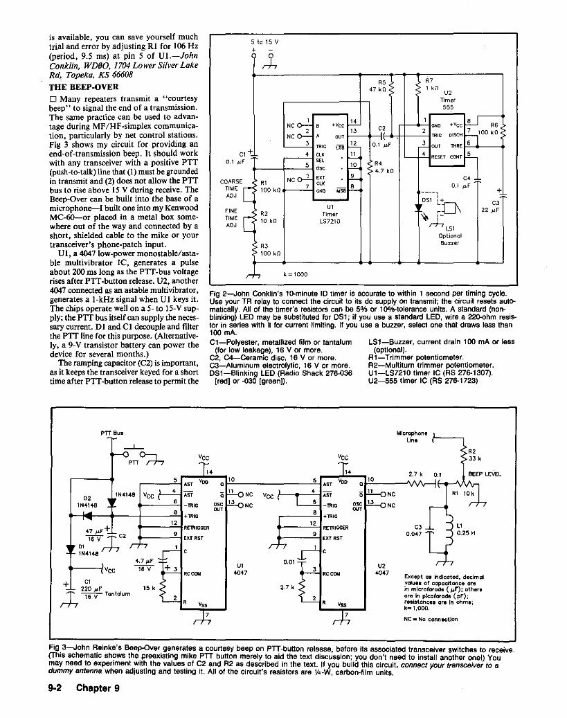
5 to 15 V+
LS1-Buzzer, current drain 100 mA or less(optional).
R1-Trimmer potentiometer.R2-Multiturn trimmer potentiometer.U1-LS7210 timer IC (RS 276-1307).U2-555 timer IC (RS 276-1723)
,LR5 R7
47 kO 1 kOU2
Timer555
1~
1 lUNC 0-:- B -vcc~~
<><0 -vcc R62 13 2 ~100kONC <>:- ,
OUT TR" DISCH
3 TR" [SB uz. 0.1 ~F ,2 OUT T1<RE
1+~ 4 CLK I-'..'.... L->.i. RESET CONT u,F '" R45 • I-!.Q...0;0
4.7 kG
NC a-2 exr .~ C4 ,R1 CLK
l!!- 0.1 ~F
[ 100 kO7
"" +'.0 ----,~DSl
,'+ C3
U1
'"~~:[J\ 22 iJF
[R2 Timer ,-10 kG LS7210
,rT7
LS1Optional
R3 Buzzer
100 kO
r.h k = 1000
C
0.1 ~
Fig 2-John Conklin's 1D-minute 10 timer is accurate to within t second per timing cycle.Use your TR relay to connect the circuit to its dc supply on transmit; the circuit resets automatically. All of the timer's resistors can be 5% or 10%-tolerance units. A standard (non- .blinking) LED may be substituted for 051; if you use a standard LED, wire a 22O-ohm resistor in series with it for current limiting. If you use a buzzer, select one that draws less than100 rnA.C1-Polyester, metallized film or tantalum
(for low leakage), 16 V or more.C2, C4-Ceramic disc, 16 V or more.C3-Aluminum electrolytic, 16 V or more.DS1-Blinking LED (Radio Shack 276-036
[red] or -030 [green)).
FINETIMEADJ
COARSETIMEADJ
is available, you can save yourself muchtrial and error by adjusting RI for 106 Hz(period, 9.5 ms) at pin 5 of Ul.-JohnConklin, WD60, 1704Lower Silver LakeRd, Topeka, KS 66608
THE BEEP-OVERD Many repeaters transmit a "courtesybeep" to signal the end of a transmission.The same practice can be used to advantage during MF/HF-simplex communication, particularly by net control stations.Fig 3 shows my circuit for providing anend-of-transmission beep. It should workwith any transceiver with a positive PTT(push-to-talk) line that (I) must be groundedin transmit and (2) does not allow the PITbus to rise above 15 V during receive. TheBeep-Over can be built into the base of amicrophone-I built one into my KenwoodMC-60-or placed in a metal box somewhere out of the way and connected by ashort, shielded cable to the mike or yourtransceiver's phone-patch input.
VI, a 4047 low-power monostable/astable multivibrator Ie, generates a, pulseabout 200 ms long as the PIT-bus voltagerises after PIT-button release. U2. another4047connected as an astable multivibrator,generates a I-kHz signal when VI keys it.The chips operate well on a 5- to 15-Vsupply; the PIT bus itself can supply the necessary current. DI and CI decouple and filterthe PIT line for this purpose. (Alternatively, a 9-V transistor battery can power thedevice for several months.)
The ramping capacitor (e2) is important,as it keeps the transceiver keyed for a shorttime after PIT-button release to permit the
PTT Bus
Except aa IndIcated. decimglvalue. of capacltgnce arein microfarads (#F'): othersore In pIcofarad. (pF");resistance. ore In ohm.;k-l.000.
NC- No connectIon
U24047
7
Vss
RCCOl<
2R
3
MicrophoneUne
R2Vce 3Jk
14 2.7 k 0.1 BEEP LEVEL5 VOD 10
AST 04 0 11 NC ., 10kAST
• -TRIG 0;0 13 NC
• OUT+TRIG
12C3 L1RETRIGGER
• 0.047 0.25 HExt RST
C
0.01
2.7 k
Ul4047
7
14vee 10
0
011 NC VCC
osc 13 NCOUT
5
c
2 R
RCCOl<
•
+3
47 ~F"+16V- T C2
01 rT7lN4148
02lN4148
.5T
lN41.B vee 4 ill.....__-"6~_TRIG
.....--Jo...- ...-----+----'.'-I +TRIG12
.....__..j 4.7~F.. vee 16 V
+ Cl220 ~F" 15 k
~~Tantalum
Fig 3-John Reinke's Beep-Over generates a courtesy beep on PIT-button release, before its associated transceiver switches to receive.(This schematic shows the preexisting mike PIT button merely to aid the text discussion; you don't need to install another onel) Youmay need to experiment with the values of C2 and R2 as described in the text. If you build this circuit, connect yourtransceiver to adummy antenna when adjusting and testing it. All of the circuit's resistors are V4-W, carbon-film units.
9·2 Chapter 9
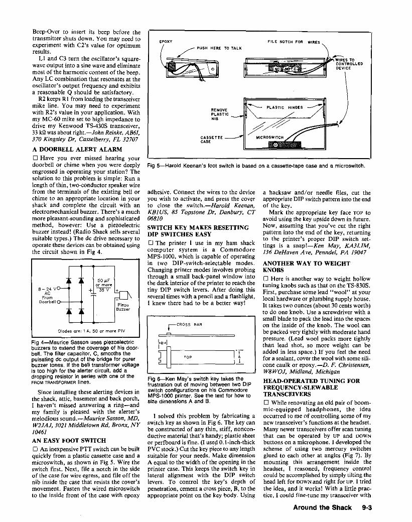
Diodes ore: 1 A. 50 or more PlY
ANOTHER WAY TO WEIGHTKNOBSo Here is another way to weight hollowtuning knobs such as that on the TS-830S.First, purchase some lead "wool" at yourlocal hardware or plumbing supply house.H takes two ounces (about 30 cents worth)to do one knob. Use a screwdriver with asmall blade to pack the lead into the spaceson the inside of the knob. The wool canbe packed very tightly with moderate handpressure. (Lead wool packs more tightlythan lead shot, so more weight can beadded in less space.) If you feel the needfor a sealant, cover the wool with some silicone caulk or epoxy.-D. F. Christensen,W8WOJ, Midland, Michigan
HEAD·OPERATED TUNING FORFREQUENCY-SLEWABLETRANSCEIVERSD While renovating an old pair of boommic-equipped headphones, the ideaoccurred to me of controlling some of mynew transceiver's functions at the headset.Many newer transceivers offer scan tuningthat can be operated by UP and DOWNbuttons on a microphone. I developed thescheme of using two mercury switchesglued to each other at angles (Fig 7). Bymounting this arrangement inside theheadset, I reasoned, frequency controlcould be accomplished by simply tilting thehead left for DOWN and right for UP. I triedthe idea, and it works! With a little practice, I could fine-tune my transceiver with
a hacksaw and/or needle files, cut theappropriate DIP switchpattern into the endof the key.
Mark the appropriate key face TOP toavoid using the key upside down in future.Now, assuming that you've cut the rightpattern into the end of the key, returningto the printer's proper DIP switch settings is a snap!-Ken May, KA3LIM,136 DeHaven A ve, Penndel, PA 19047
/77MICROSWITCH
REMOVEPLASTICNI.
CASSETTE ---"CASE
/ PUSH HERE TO TALK
tCROSS BAR
EPOXY
n
Fig 5-Harold Keenan's foot switch is based on a cassette-tape case and a microswitch.
Fig 6-Ken May's switch key takes thefrustration out of moving between two DIPswitch configurations on his CommodoreMPS-1000 printer. See the text for how tosize dimensions A and B.
adhesive. Connect the wires to the deviceyou wish to activate, and press the coverto close the switch.-Harold Keenan,KBI US, 85 Topstone Dr, Danbury, CT06810
SWITCH KEY MAKES RESETTINGDIP SWITCHES EASYo The printer I use in my ham shackcomputer system is a CommodoreMPS-lOOO. which is capable of operatingin two DIP-switch-selectable modes.Changing printer modes involves probingthrough a small back-panel window intothe dark interior of the printer to reach thetiny DIP switch levers. After doing thisseveral times with a pencil and a flashlight,I knew there had to be a better way!
I solved this problem by fabricating aswitch key as shown in Fig 6. The key canbe constructed of any thin, stiff, nonconductive material that's handy; plastic sheetor perfboard is fine. (I used O.l-inch-thickPVC stock.) Cut the key pieceto any lengthsuitable for your needs. Make dimensionA equal to the width of the opening in theprinter case. This keeps the switch key inlateral alignment with the DIP switchlevers. To control the key's depth ofpenetration, cement a cross piece, B, to theappropriate point on the key body. Using
PlezcBuzzer
50,uFor more
+ 3'5V +8- 24 VAC
FromDoorbell o---+-~
Since installing these alerting devices inthe shack, attic, basement and back porch,I haven't missed answering a ring-andmy family is pleased with the alerter'smelodious sound.-Maurice Sasson, MD,W2JAJ, 3021 Middletown sa, Bronx, NY10461
AN EASY FOOT SWITCHo An inexpensive PTT switch can be builtquickly from a plastic cassette case and amicroswitch, as shown in Fig 5. Wire theswitch first. Next, file a notch in the sideof the case for wire egress, and file off thenib inside the case that resists the cover'smovement. Fasten the wired microswitchto the inside front of the case with epoxy
Beep-Over to insert its beep before thetransmitter shuts down. You may need toexperiment with C2's value for optimumresults.
LI and C3 turn the oscillator's squarewave output into a sine wave and eliminatemost of the harmonic content of the beep.Any LC combination that resonates at theoscillator's output frequency and exhibitsa reasonable Q should be satisfactory.
R2 keeps Rl from loading the transceivermike line. You may need to experimentwith R2's value in your application. Withmy MC-60 mike set to high impedance todrive my Kenwood TS-430S transceiver,33 kll was about right.-John Reinke. AB61,370 Kingsley Dr, Casselberry, FL 32707
A DOORBELL ALERT ALARMo Have you ever missed hearing yourdoorbell or chime when you were deeplyengrossed in operating your station? Thesolution to this problem is simple: Run alength of thin, two-conductor speaker wirefrom the terminals of the existing bell orchime to an appropriate location in yourshack and complete the circuit with anelectromechanical buzzer. There's a muchmore pleasant-sounding and sophisticatedmethod, however: Use a piezoelectricbuzzer instead! (Radio Shack sells severalsuitable types.) The dc drive necessary tooperate these devices can be obtained usingthe circuit shown in Fig 4.
Fig 4-Maurice Sasson uses piezoelectricbuzzers to extend the coverage of his doorbell. The filter capacitor, C, smooths thepulsating de output of the bridge for purerbuzzer tones. If the bell transformer voltageis too high for the alerter circuit, add adropping resistor in series with one of theFROM TRANSFORMER lines.
Around the Shack 9-3

Fig 7-Bob Nagy's head-operated tuningscheme uses two mercury switches as UPand DOWN frequency-slewing controls.Mounted in a headset, they allow hands-offfrequency excursions with rigs that includethis feature. See text.
10 kn
011N914
DO~
(Ot----S R1 o.osALC OUT
RF IN RF!
~t,
without retuning the amplifier-to thatsuggested by the amplifier manufacturerfor safe RTTY operation.-Hal Cupps,W7LBD, 5833 E Onyx A ve, Scottsdale, AZ85253
USING DESK MIKES WITH THEKENWOOD TR-2S00 AND OTHERTRANSCEIVERS
D The MC-60A and -50 microphones, andmany other desk mikes intended for usewith Amateur Radio transceivers havingfour- or eight-pin mike connectors, can beused with the TR-2500 and other hand-heldtransceivers by installing a simple adapterin the mike line. This is especially convenient for fixed-station operation becausedesk mikes generally allow "lock-to-talk"operation that hand-helds' PTT buttonsdon't.
The adapter (Fig 9) consists of a fouror eight-pin male mike jack, a suitablelength of mike cable, a piece of insulated,stranded hookup wire the same length asthe mike cable, a miniature phone plug (tomatch the hand-held's mike jack) and asmall alligator clip.
Wire the adapter as shown in Fig 9 andwind the ground wire around the mikecable. Attach the alligator clip to the transceiver chassis ground at the rig's antennajack or carrying-strap bracket. If your
eo kflALC AOJ
10 sn
Fig a-Hal Cupps uses this circuit toproduce adjustable ALC voltage in hisRTTY system. The polarity of 01 determines the polarity of the ALe signalproduced. As shown here, the circuitproduces a negative voltage with respect toground. C1 consists of a 3f4-inch-squarepiece of double-sided PC board (Cl 's leadsgo to opposite sides of the board). 01 maygenerate harmonics of the applied signal;because harmonics can cause interferenceto radio and TV reception, check receptionof your local radio and TV signats afteryou've added the circuit to your station tobe sure 01 isn't causing interference. If01~generated interference occurs, low-passfiltering between C1 and the antenna cansolve the problem.
Through experimentation, I determinedthat the headset's mike element works wellwith the voltage and polarity present at myKenwood TR-2600A's mike jack. (The'2600A's mike line sources 4 V de [centerconductor, positive] for use with capacitormike elements.) The TR-2600A drives theheadset earphone well.
Attempts to drive the headset's 17-inchwhip failed until 1 discovered and removedthe whip's inductive loading. To take theloading inductor out of the circuit, unscrewthe earphone cover and lift the earphoneelement to one side. Solder a short pieceof solid wire across the inductor terminals,and reassemble the headset. Modified inthis way, the headset whip-somewhatshorter than ~ A, I admit-works on 2meters at a reasonable SWR and providescommunication over a greater range thana "rubber duckie."
For remote PIT switching, I mounteda SPST switch in a 35-mm-film can, andconnected the switch to the mike-jack PTTterminals with two-wire cable. Clipped tomy belt with a key-ring clip, this arrangement makes TR switching easy.
Of course, suitable connectors must beinstalled on the headset earphone wires,and antenna and microphone cables; because the connectors required vary withthe application, 1 leave these details toyou.-AI Brogdon, K3KMO, Box 60,Damascus, MD 20872
BETTER AUDIO QUALITY FROM ANOUTBOARD SPEAKER
D 1 have a hearing disability that requiresbassier response and more audio outputthan my stock Kenwood SP·930 speakercould provide without objectionable distortion. I improved the power-handlingcapability and frequency response of the'930 by replacing its speaker with a 4-inchRadio Shack'" automobile speaker (RS40-1197). This replacement speaker exactlyfits the mounting holes in the SP-930! Next,I lined the speaker cabinet with fiberglassinsulation (RS 42-1082 or equivalent) todamp acoustic resonances.
Modified in this way, the SP-930 handlesthe full audio output from my TS-930transceiver without noticeable distortion,and its frequency response is substantiallyimproved. The outboard speakers used bymany hams can probably be improved bysimilar modifications.-Maurice Sasson,MD, W2JAJ, New Rochelle, New York
ALC FOR RTTY OPERATIOND As a radioteletype (RTTY) enthusiast,I've been frustrated by incompatibilitybetween transceivers and the automaticlevel-control (ALC) output of variousexternal power amplifiers. An externalALC circuit (Fig 8) suggested to me byErwin Weber, W9DBM, has proven quitesuccessful in solving this problem. With thiscircuit in place, I can adjust my amplifierfor linear operation and, by adjusting Rl,reduce the amplifier's' output power-
UP1
DOWN
~IMERCURYSWITCHES
$'ENABLE
UP
quick nods to either side.This little modification has applications
for handicapped hams. of course, but it'sa neat idea for anybody's shack. Be sureto include a switch (81) to turn the circuiton and off, though: If you forget that thehead-operated tuning is operative. you maythink other stations are drifting every timeyou scratch your head!-Bob Nagy,WA2TMD, 3303 Larry Ln, Austin, TX78722
A GOOD, CHEAP HEADSET
o Several headsets on the market are useful for mobile and hand-held-transceiveroperation. Most of these headsets cost $40to $50, and others cost up to $80. Here isa cheaper way to get a good headset.
Radio Shack" catalog no. 432 includes"voice-actuated FM headset walkietalkies"on page 70. Each of these units includes a headset consisting of a microphone, one earphone and a 17-inchearphone-mounted whip antenna. You canorder a replacement headset (Part no.Z-7868) through a Radio Shack store [andperhaps through Tandy National PartsEd.]. The price of the headset at the time1 bought it was $10.18 plus tax!
The earphone cable consists of twocoaxial cables (one with a clear-plasticinsulated center conductor and gray shieldwire, and the other with a gray-plasticinsulated center conductor and black shieldwire) and two single leads (one blue, oneblack). The clear-insulated-center-conductor coax carries RF; the black-insulatedcenter-conductor coax carries microphoneaudio. (The microphone uses an electretcapacitor element; in addition to audio, themike cable carries voltage for the mike element.) The single blue and black wirescarry earphone audio.
9·4 Chapter 9
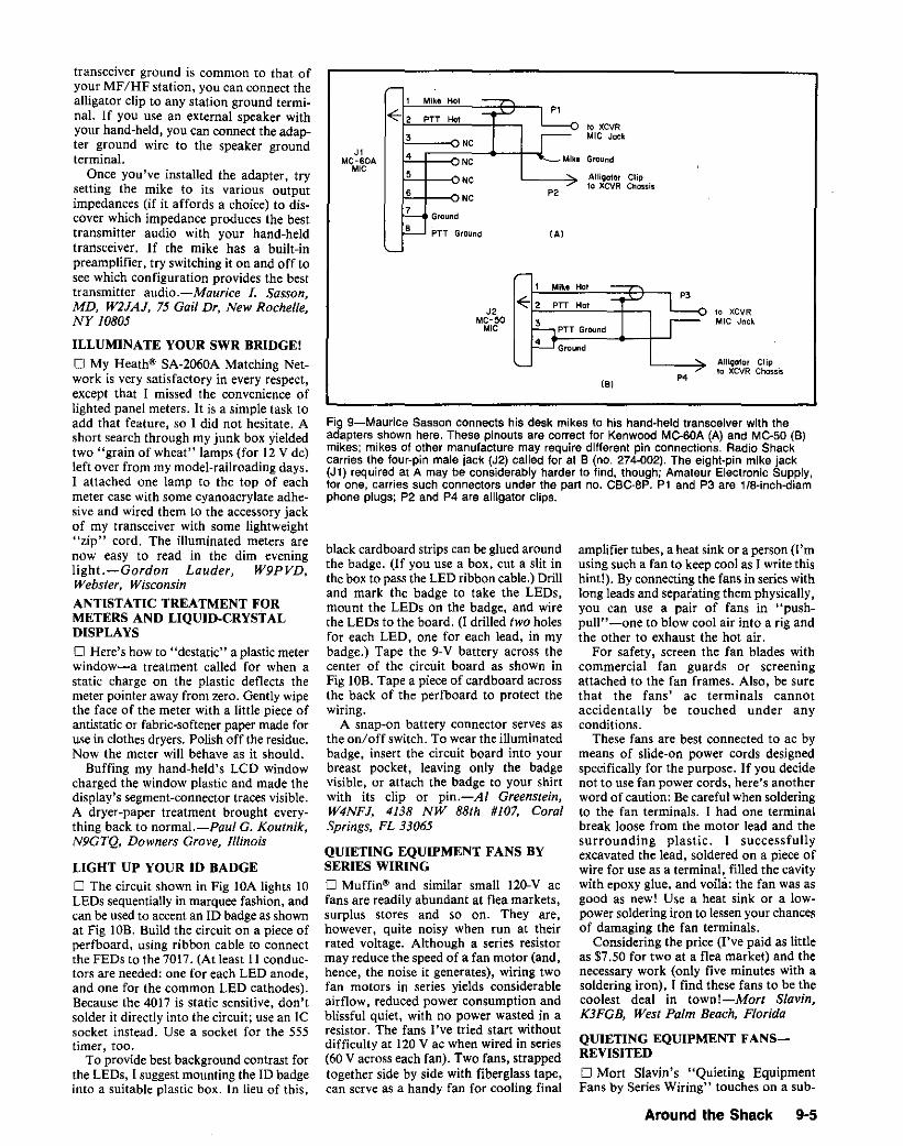
Fig 9-Maurice Sasson connects his desk mikes to his hand-held transceiver with theadapters shown here, These pinouts are correct for Kenwood Me-BOA (A) and Me-50 (B)mikes; mikes of other manufacture may require different pin connections. Radio Shackcarries the four-pin male jack (J2) called for at B (no. 274--002). The eight-pin mike jack(Jl) required at A may be considerably harder to find, though; Amateur Electronic Supply,for one, carries such connectors under the part no. eSC-B? Pl and P3 are lIB·inch·diamphone plugs; P2 and P4 are alligator clips.
1 Mike Hoi
<E-, P1err Ho1
to XCVR3
NCMIC Jack
J1 4MC-60A NC Mike Ground.,C e NC AlliQator Clip
610 XCVR Chossis
NC P'
7Graund
6 PTY Ground {A'
Alligator Clip10 XCVR chcsse
10 XCVRMIC Jock
P4
amplifier tubes, a heat sink or a person (I'musing such a fan to keep cool as J write thishint!). By connecting the fans in series withlong leads and separating them physically,you can use a pair of fans in "pushpull"-one to blow cool air into a rig andthe other to exhaust the hot air.
For safety, screen the fan blades withcommercial fan guards or screeningattached to the fan frames. Also, be surethat the fans' ac terminals cannotaccidentally be touched under anyconditions.
These fans are best connected to ac bymeans of slide-on power cords designedspecifically for the purpose. If you decidenot to use fan power cords, here's anotherword of caution: Becareful when solderingto the fan terminals. J had one terminalbreak loose from the motor lead and thesurrounding plastic. I successfullyexcavated the lead, soldered on a piece ofwire for use as a terminal, filled the cavitywith epoxy glue, and voila: the fan was asgood as new! Use a heat sink or a lowpower soldering iron to lessen your chancesof damaging the fan terminals.
Considering the price (I've paid as littleas $7.50 for two at a flea market) and thenecessary work (only five minutes with asoldering iron), I find these fans to be thecoolest deal in town!-Mort Slavin,K3FGB, West Palm Beach, Florida
QUIETING EQUIPMENT FANSREVISITED
o Mort Slavin's "Quieting EquipmentFans by Series Wiring" touches on a sub-
{B'
Ground
PTT Ground
Mike Hat
3
4
J2MC-50.,C
black cardboard strips can be glued aroundthe badge. (If you use a box, cut a slit inthe box to pass the LED ribbon cable.) Drilland mark the badge to take the LEOs,mount the LEDs on the badge, and wirethe LEOs to the board. (I drilled two holesfor each LED, one for each lead, in mybadge.) Tape the 9-V battery across thecenter of the circuit board as shown inFig lOB. Tape a piece of cardboard acrossthe back of the perfboard to protect thewiring.
A snap-on battery connector serves asthe on/off switch. To wear the illuminatedbadge, insert the circuit board into yourbreast pocket, leaving only the badgevisible, or attach the badge to your shirtwith its clip or pin.-AI Greenstein,W4NFJ, 4138 NW 88th #/07, CoralSprings, FL 33065
QUIETING EQUIPMENT FANS BYSERIES WIRINGo Muffin" and similar small 120-V acfans are readily abundant at flea markets,surplus stores and so on. They are,however, quite noisy when run at theirrated voltage. Although a series resistormay reduce the speed of a fan motor (and,hence, the noise it generates), wiring twofan motors in series yields considerableairflow, reduced power consumption andblissful quiet, with no power wasted in aresistor. The fans I've tried start withoutdifficulty at 120 V ac when wired in series(60 V across each fan). Two fans, strappedtogether side by side with fiberglass tape,can serve as a handy fan for cooling final
transceiver ground is common to that ofyour MF/HF station, you can connect thealligator clip to any station ground terminal. If you use an external speaker withyour hand-held, you can connect the adapter ground wire to the speaker groundterminal.
Once you've installed the adapter, trysetting the mike to its various outputimpedances (if it affords a choice) to discover which impedance produces the besttransmitter audio with your hand-heldtransceiver. If the mike has a built-inpreamplifier, try switching it on and off tosee which configuration provides the besttransmitter audio.-Maurice I. Sasson,MD, W2JAJ, 75 Gail Dr, New Rochelle,NY 10805
ILLUMINATE YOUR SWR BRIDGE!
o My Heath'" SA-2060A Matching Network is very satisfactory in every respect,except that I missed the convenience oflighted panel meters. It is a simple task toadd that feature, so I did not hesitate. Ashort search through my junk box yieldedtwo "grain of wheat" lamps (for 12 V dc)left over from my model-railroading days.I attached one lamp to the top of eachmeter case with some cyanoacrylate adhesive and wired them to the accessory jackof my transceiver with some lightweight"zip" cord. The illuminated meters arenow easy to read in the dim eveninglight.-Gordon Lauder, W9PVD,Webster, WisconsinANTISTATIC TREATMENT FORMETERS AND LIQUID-CRYSTALDISPLAYS
o Here's how to "destatic" a plastic meterwindow-a treatment called for when astatic charge on the plastic deflects themeter pointer away from zero. Gently wipethe face of the meter with a little piece ofantistatic or fabric-softener paper made foruse in clothes dryers. Polish off the residue.Now the meter will behave as it should.
Buffing my hand-held's LCD windowcharged the window plastic and made thedisplay'S segment-connector traces visible.A dryer-paper treatment brought everything back to normal.-Paul G. Koutnik,N9GTQ, Downers Grove, Illinois
LIGHT UP YOUR ID BADGED The circuit shown in Fig lOA lights 10LEOs sequentially in marquee fashion, andcan be used to accent an ID badge as shownat Fig lOB. Build the circuit on a piece ofpertboard, using ribbon cable to connectthe FEDs to the 7017. (At least II conductors are needed: one for each LED anode,and one for the common LED cathodes).Because the 4017 is static sensitive, don'tsolder it directly into the circuit; use an lCsocket instead. Use a socket for the 555timer, too.
To provide best background contrast forthe LEOs, I suggest mounting the 1Dbadgeinto a suitable plastic box. In lieu of this,
Around the Shack 9-5

~r-~ r-~ ~ ~ l-~r-~l-~ r-~ ~j ,.. ,
~ .~ j Ito ' ~ ,Ito j Ito ' ~ j ,.. j ,..3 2 • 7 '0 1 5 , • 11
00 01 02 03 O' 05 0' 07 0' O.~V"
o---E CARRYCOUNTER RESET~OUT
Ul eLK EN~17 CW< Vgo
14 " BTl
0.01 IJ.F o-t1lllli-=--25 V
" • Vr:
f----..!. GNO
r: TRIG F------TIMER
NCo2 CTRL. THR~ ~, "3
OUT >1 k
DISCH 7U2 RESET Voe
555
I' a
SEQUENCE NUMBER
NC
2 3 • 5 , 7 • • 10Fig 1O-AI Greenstein's IO-badge-Ughtingcircuit (A) uses a 4017 decade counter anda 555 timer to light 10 LEOs sequentially.Resistors are V4 W; a snap-on batteryconnector serves as the on/off switch. AI'ssuggested badge/board configuration isshown at B.
1 • 2. 3. ••• W4NFJ •10 AL 5
•• ., .7 .,
~
BTl PP
§J
(8)
ject of interest to many radio amateursbecause "bargain" fans purchased byhamsat flea markets may run too fast, or tooloudly, to be useful. Mr. Slavin's methodrequires the presence of two fans; how canone fan be slowed effectively?
Fan noise is related to the physical designand integrity of the fan in addition to itsrate of rotation. Vibration from worn-outbearings-quite commonin usedor surplusfans-can cause considerable noise if it isconducted to the enclosure (if any) in whichthe fan and associated equipment arehoused. If the enclosure happens toresonate at the fan's vibration frequency,this noise can be severe. Slowing a fanmakes the fan run quieter by reducing bladeturbulence and lowering the frequency ofthe fan's vibration(s).. Continuousoperationof a fan below itsdesign speed may be harmful to the fan inthe long run, however. This is so becausethe fan is designed to cool itself in additionto the equipment associated with it.Slowed, a fan may be undercooled by itsown air flow and run hot, especiallyat highambient air temperatures.
An appropriate compromise to theconflicting problems of fan noise andinsufficient fan cooling is to link fan speedand air temperature. The simplest meansof achievingthis is a resistor in series with
9·8 Chapter 9
,.
---120 VAC-----<)
Fig 11-Joachim Wollw~ber suggests usinga series capacitor, C, Instead of a resistorto slow and quietac powered fans. A thermostatic switch can be added to achieve aworkable compromise between fan noise,fan life and equIpment cooling; see text.
the fan, with a thermostat in parallel withthe resistor. Choose a thermostat that (I)operates at the desired temperature; (2)closes with rising temperature; and (3) iscapable of switching the fan power supply.Properly installed, such a thermostat willallow the fan to run at full speed to coolitself and its associated equipment aboveits trigger temperature; at airtemperatureslower than this, the thermostat will opento allow the series resistor to slow (andquiet) the fan.
A series resistor is an inefficient meansof slowinga cooling fan. however, because
it dissipates power as heat. An ae-ratedcapacitor of sufficient reactance to slow thefan to the desired speed-and capable ofsafely handling the fan current-is a bettersolution. Fig 11 shows how a fan-slowingcapacitor can be applied in conjunctionwith a thermostat.
The capacitance required dependsuponthecharacteristics and powerconsumptionof the fan motor. Insufficientcapacitancewill keep the motor from starting; toomuch capacitance will allow the motor toreachits normal(noisy) speed. The propervalue can be determined by installinginsufficient capacitance to start the fan.Increase the value of thiscapacitance untilthe fan starts. [Safety first: Be sure todisconnect the fan circuit from the aesupply before adjusting the slowingcapacitance.-AK7M]
Once you have determined the value ofthe fan-slowing capacitor, experiment tofind the best location for the thermostat.Positioning the thermostat as closelyas possible to the heat source should allow thethermostat to respond quickly to temperature variations at the heat source. A thermostat that actuates at a temperaturesomewhat lower than the target temperaturemay be of use in achieving this aim.-Joachim Wollweber, DF5PY, Schillerplatz18 A, 6500 Main:. West Germany

SAFETY SCREEN FOR COOLINGFANS
o For added protection of transceiver fansin cylindrical cowlings: Cut a piece of plasticwindow screening and secure it over the fancowling with a hose clamp or a strongrubber band. This keeps children's fingersand slim projecting objects out of the fanespecially important when the rig is usedoutside of the controlled environment of thehome station.-Clyde C. Blake, KA1BSZ,Ely, Vermont
COAX-SHIELD CHOKE CURESTRANSCEIVER SELF-OSCILLATION
o The Yaesu FT-747GX transceiver is verysensitive to return currents on the outsideof its coaxial feed lineand sometimes goesinto oscillation even at SWRs near I: 1. Icured this problem in my station by installing a coax-line RF choke betweenthe transceiver and anything else it's connected to.The choke consists of a 6-inch-diameter I
lO-turn coax coil like that shown in Chapter26 of The ARRL Antenna Book and Chapter 16 of The ARRL Handbook for RadioAmateurs? A friend of mine had a similar problem with a Kenwood TS-I40S; acoax-shield choke solved that problem veryeffectively, too.-Jay M. Jeffery, WV8R,3819 Parkdale Rd, Cleveland Hts, OH44121
2A ferrite-bead choke, described in the AntennaBook and Handbook along with the coax-coilbalun, will probably work, too.-WJ1Z
MORE ON SAFE AC·WIRINGPRACTICES
o Larry Wolfgang's "Safe Ac-PowerWiring Practices"! reminds me that it'simportant for us to be aware of the properway to connect fuses, power switches andac receptacles. We hams can further addto the safety of our equipment by incorporating two safety features as specified insome European safety regulations:
Panel-mounted (axial, plug-in) fuseholders-Connect the end of the fuseholder that is farther from the panel to theline. Connect the end nearer the panel tothe load. This ensures that the fuse touchesonly the holder's equipment-side terminaluntil you insert the fuse to a depth at whichyour fingertips can't touch the fuse cap'smetal contact.
Power switches-Use a double-polepower switch or relay that interrupts bothsides of the line (hot and neutral in 120-Vsystems, and both hot wires in 240-V systems). This ensures maximum safety in240-V systems, and safe disconnection of120-V devices under conditions wheresystem-wiring polarity may be questionable(such as when nonpolarized plugs arepresent).-Charles P. Baker, W2KTF,2715 Wilson Ave, Bel/more, NY U7IO
3L.Wolfgang, ed, HintsandKinks,QST, Apr 1984,pp 42-43, and reprinted in The ARRl Bookshelf's 12th edition of Hints and Kinks for theRadio Amateur.
QUICK POWER AND ANTENNADISCONNECTS FOR EQUIPMENTLIGHTNING SAFETY
o Summer is almost upon us, and with itcome unexpected, violent thunderstorms.Like every ham, 1quickly dash to the shackto disconnect coax and pull power plugs atthe first loud thunderclap to protect my investment in amateur gear. This behaviorconditions other family members: My nonham husband awakens me out of a deepsleep to announce an impending storm with"Your radios!"
This is fine if the ham is home and canattend to the situation. When the ham isn '(home, one of the family's nonhams mayattempt to do this simple chore. Alas,he/she is confronted with a vast conglomeration of cables, patch cords, coax and whatnot. Having no idea where to begin, theymay indiscriminately disconnect everythingin sight, leaving your station in completedisarray. (I speak from experience!)
1 solved this problem by simplifying andstreamlining equipment disconnection. Allmy equipment plugs into heavy-duty acoutlet strips, making it simple to pull theplugs first. Then I identified the coaxialjumper that absolutely has to be pulled: theone that protects the most equipment.About 3 inches up the cable from itsPL-259 connector, I wound a piece ofmasking tape around the coax and paintedit red. (Marking one such-jumper may notbe enough: You may need to label an additional cable for VHF/UHF equipment.)
Now, even my kids know: If I'm nothome, pull the plugs and disconnect the redcoax I-Claudia J. Lang, KC3GO, 3444Bench Dr, Pittsburgh, PA 15236WJ1Z: The sensitive electronics common inmodern Amateur Radio stations can bedamaged by the current induced by lightningstrokes miles away; in fact, weather-inducedstatic damage can occur even if lightning isabsent. So, protecting your gear against atmospheric electricity is a good idea. The bestway to do this is to keep your gear entirely disconnected from power, ground and antennawiring when you're not using It. This end-runsthe questions of whether or not someone willdisconnect the gear in time, and whether ornot they'll be safe as they do so. Some background:
• This hint describes a precaution againstindirect lightning strokes-a precaution thatdoes not substitute for the protection affordedby the proper grounding and lightning suppression necessary in every outdoor antenna system. Indoor antennas can be struck, too.
• Disconnecting antenna and ac-powerleads may not fully protect gear left connectedto ground. The best way to protect station elec·tronic equipment against lightning damage isto disconnect all wires from the equipment andmove the equipment away from station wiresand cables.
• If severe weather is already so close thatyou can see lightning flashes andlor hear thunderclaps, you may be risking your life by disconnecting antenna, ground and power leads;Keep a weather eye out and disconnect yourgear well before severe weather moves intoyour area; better yet, keep it disconnectedwhenever you're not using it.
Also consider applying Claudia's big redswitch idea to your station's ac supply. Installand identify a main ac-eutoff switch in your station. (Such a switch does not constitute lightning protection; lightning capable of leapingthousands of feet through the sky won't stopat a fraction-of-an-inch air gap!) Instruct familymembers on how to kill the power swiftly andsafely if an electrical emergency-electricalshock, for instance-occurs in your station.Get everybody on the same wavelength aboutwhat to do and who to call if the unthinkablehappens. Every second counts.
WATER MAKES DRIVING GROUNDRODS EASIER
o Water from a garden hose can ease driving a tubular ground rod. All you need isa small hose clamp and a short piece ofIll-inch-QD flexible plastic tubing connectedto a !h.-inch female hose fitting. Hoseclamp the free end of the plastic tubing tothe ground tube. Turn on the water andpush the open end of the ground tube intothe ground. You'll feel a little resistancewhen the tube meets packed soil, butpulling the tube out an inch or so and tryingagain will usually clear the way. If you hita rock, pull the tube out and try again afew inches away.
Using this technique, I installed twoground rods in 10 minutes. The parts forthe hose adapter cost less than $2.-BobHinshaw, WD6L, 5910 Vicente St, Chino,CA 91710
INEXPENSIVE GROUND WIRE
D When installing an extensive groundsystem for a new tower, I needed about 20ft of no. 8 copper wire. I was shocked tolearn that it would cost me 65 cents perfoot! After some research and a fewcalculations, I found that there was acheaper equivalent.
1 consulted the ARRL Handbook'scopper wire table and learned that thecross-sectional area of no. 8 wire is 16,510circular mils (cmils), On a hunch-andhaving recently purchased 250 ft of no. 14Romex cable (with ground wire, whichmade it a three-conductor bundle) for $25,or about 10 cents per foot-I also notedthat the cross-sectional area of no. 14 wireis 4107 cmils. My hunch was confirmed:doubled three-wire Romex (6 x no. 14)would serve at least as well as a single no.8 conductor-at less than 1/6 the cost ofthe no. 8 wire!
1 cut 40 ft of the Romex and stripped allthree wires in the bundle. Then 1 doubledeach wire (folded each back on itself) andclamped the free ends (six) in a vise. Placinga screwdriver through the three folded wireends, I twisted the wires until they werebundled so tightly that they looked likethey'd been manufactured that way.Result: 20 ft of wire that was closer to no.6 wire than no. 8 in cross-sectional area-ata cost of $4 versus $13 for 20 ft of no. 8!-Stan Barczak, K8MJZ, 11220ChurchillRd, Rives Jet, MI49277
Around the Sheck 9-7

Fig 13-:-Ma~in Cardwell's addition of a transceiver-to-amplifier matching network (Network2) to hIS statl!?n cured p.r!?blems related to impedance mismatch between his transceiverand un~un~d.mput amplifier, N~twork 1 matche,s the antenna to the amplifier output or thetransceiver s antenna Input, This arrangement IS somewhat inconvenient because Network2 must .be switch,ed out of the line when the antenna is to be connected directly to thetransceiver. Martm solved this problem by modifying his amplifier and reconnectingNetwork 2 as shown in Fig 14.
fier-protection circuitry to significantlyreduce the transceiver's output on allbands. The problem was so bad that Icouldn't use the amplifier at all onto meters. (The transceiver, a KenwoodTS-930S, contains an automatic antennatuner, but the amplifier input impedanceis evidently outside the tuner's matchingrange.)
To solve this problem, I installed ahomemade pi matching network (twovariable capacitors and a roller inductor)in the coax line between the transceiver andthe amplifier as shown in Fig 13. (Mystation already included a matchingnetwork between the antenna and theamplifier [between the antenna and thetransceiver with the amplifier off-line]. I'llrefer to the antenna-to-amplifier matchingnetwork as Network I from now on. Thetransceiver-to-amplifier network will bereferred to as Network 2.) Properly adjusted, this network allows the TS-930S todrive the Clipperton on all of my bands ofinterest, including 10 meters. (The TS-930'sability to meter output power and SWR issomething new to me. If you use anamplifier, and you've never monitored theSWR between your exciter and amplifierwith the amplifier operating, you may bein for a big surprise! From now on, I'llrefer to SWR meter between the amplifierand antenna as SWR meter 1j the transceiver SWR meter is SWR meter 2.) I rana series of tests to find the necessary settings for Networks I and 2, and recordedthese settings for later reference. Now I canchange bands quickly without on-airtestings by presetting the matchingnetworks to the recorded values.
Smooth amplifier in/out switching wasmy next concern. I couldn't just leave bothnetworks in the line at all times; switchingthe amplifier off-line connects both networks in series and allows them to interact.To get around this, I modified theClipperton L amplifier as shown in Fig J4and connected Network 2 as indicated.Now, Network 2 is used only to match thetransceiver to the amplifier, At othertimes-during receive when the amplifieris in line, and during transmit and receivewhen the transceiver is used on its ownonly Network 1 is present between theantenna and the transceiver.
lA'
RELAY ECOIL
RELAY E
RELAY C
n--------<lL __~~PTT
RELAY A
ADDITIONAL RELAY A AND CCONTACTS NOT SHOWN
16'
12V
NC· NO CONNECTION
~ELAY A
12 V TO PREAMP12'1 1l2V RX, 0 V TX)
12 'ITOPREAMP
Fig 12-John Siegel modified the TRsequencing circuitry of his GaAsFET2-meter preamp for fail-safe operation byadding a DPDT relay to the unit. Theoriginal preamp power and PIT switchingcircuit is shown at A; B shows the modifiedarrangement. Note that relay E is shown inthe energized position. See text.
in time. If relay E sticks momentarily, thekeying delay will be no shorter than therelease time of relay E. Even if thishappens, transmission into the preamp isimpossible.
Although I haven't investigated this,a more elegant solution to this TRswitching problem would modify thesequencer so that the timing for theMM144VDG's relays B, C and D isdependent upon the operation of relayA.-John Siegel, K4BNC, 4 Quincy St,Marlboro, NJ 07446
USING SOLID-STATE TRANSCEIVERSWITH UNTUNED-INPUT AMPLII1ERS
D The untuned input circuit of myDentron Clipperton L amplifier caused mynew transceiver's SWR-driven final-ampli-
Transceiver0",
SWR Meter 2
MAYBE YOU NEED TO RESET THEMICROPROCESSOR
o Most late-model ham equipment ismicroprocessor-controlled. Occasionally,the microprocessor in such a radio may"lock up" for some reason, rendering theequipment useless. Working part-time at anAmateur Radio store, I've seen many rigsbrought in for repair that required norepair other than resetting their microprocessors-a simple task that could havebeen done by their owners!
Reset procedures vary from radio toradio. In some cases, a panel button mustbe pressed as the equipment is powered up.Other gear requires that a toothpick orpencil be used to activate a switch througha small hole in the equipment case. Yourtransceiver's operating manual probablydetails the procedure necessary to reset therig's microprocessor.
Certainly, all failures in state-of-the-artradios aren't caused by locked-up microprocessors. But it never hurts to give thereset procedure a try-you might saveyourself a trip and a service charge.-Michael A. Czuhajewski, WA8MCQ,Box 232, Jessup, MD 20794AK7M: Resetting a rig's microprocessor (alsocalled a micro for short, or CPU [centralprocessing unit]) may involve one undesirableside-effect: the erasure of frequency, mode,repeater split and other information in memorychannels. Be sure to record such informationbefore you try a reset!
BETTER TRANSMIT PROTECTIONFOR GaAsFET PREAMPS
o My mast-mounted 2-meter GaAsFETpreamp (an Advanced Receiver ResearchMMI44VDG) was damaged on transmitdespite the fact that I was using themanufacturer's TR sequencer.
Fig 12A shows a portion of theMMI44VDG's sequencer output circuit;it's similar to the time-delay generator inrecent ARRL Handbooks. Normally, whenthe mic PIT button is pressed, relay Aopens immediately to take the preamp outof the line, and relay C closes after a setdelay to key the transceiver. If relay A failsto operate or sticks for a period longer thanC's delay (the apparent failure mode in mycase), however, it's possible to transmit intothe preamp.
A simple, albeit brute-force, solution tothis problem is to add a DPDT relay (relayE) as shown in Fig 128. Relay E is energized in receive and must release to allowits normally closed contacts to key thesystem transceiver. This ensures that powerhas been removed from the preamp beforetransmission begins. To guarantee thatrelay E is operational-preventing recurrence of the original failure mode-one setof relay E NO contacts is connected in series with the preamp power. If relay E fails,the preamp is turned off.
With relay E in place in the MMl44VDG,transmit timing is unchanged, but returnto receive is delayed by the relay E's pull-
9-8 Chapter 9

Fig 14-This amplifier modification Connects Network 2 between the transceiver and amplifier input only when the amplifier is used in transmit. Atatl other times, the transceiver is connected toNetwork 1 via the amplifier TR relay. Network 2 ispermanently connected between the coaxial jackslabeled N2 IN and N2 OUT.
breakconnection
to anode chokeand outputnetwork
tofilament..-----i choke
V= four 5728sin parallel
N2 OUTN2 IN
+ amplifierYoutput
existingTR relay
EXCITER
ANT
(to
SWR Meter
I adjust the system for equal SWR in the"amplifier in" and "amplifier out" modesas follows: With the amplifier switched offand the transceiver producing about 30 Woutput, adjust Network 1 for minimumSWR as indicated by SWR meter I. Turnon the amplifier and tune it up at reducedoutput power. Adjust Network 2 for minimum SWR as indicated by SWR meter 2.
A closing speculation: Some vacuumtube power amplifiers include grid-currentmetering. Grid current can serve as anindication of drive, but I don't think it canreveal conditions of unacceptably highamplifier-input SWR. Reason: Eventhough the impedance of my ClippertonL's input circuit is not SO 0, I had notrouble driving the amplifier sufficientlyas indicated by grid current-with TS-520Sand -820S transceivers.-Martin L.Cardwell, NB3 T, 4600 White Ave,Baltimore, MD 21206
AK7M:'Martin is right. The presence of ratedgrid current in an amplifier tube indicatesonlythat the tube is receiving enoughdriveto causethat grid current to flow. How well the tube ismatched to its driver must be determined byother means.
DOES YOUR SOLID-STATETRANSCEIVER REDUCE ITS OUTPUTPOWER WITH RISING SWR BECAUSEIT'S SOLID-STATE?
o You've probably heard that, in general,amplifiers, transmitters and transceiversthat use vacuum-tube RF power amplifiers"don't care" what SWR they operate into.You've probably also heard thatcommercially manufactured, solid-state,Amateur Radio amplifiers, transmittersand transceivers reduce their output poweras SWR rises. In print, at club meetings andon the air, the story seems to be that solidstate gear "has a problem with SWR" andvacuum-tube gear doesn't. What gives?How much of solid-state gear's famedinability to deal with rising SWR is myth,and how much of it is fact? What does tubegear have that solid-state gear doesn't?
Fact: Whether or not a transceiver ortransmitter reduces its output power inresponse to rising SWR is not necessarilyrelated to the type ofactive device used inits final amplifier stage. Many current,commercially manufactured AmateurRadio transceivers do reduce their outputpower in response to rising SWR. Thisfeature is generally built into the RF poweramplifier section of amplifiers, transmittersand transceivers that use bipolar junctiontransistors (BJTs) as RF power amplifiers.BJTs require such protection if they cannottolerate the collector-voltage peaks that canoccur in the presence of significant loadmismatches. The BJTs used as final RFpower amplifiers in today's commerciallymanufactured Amateur Radio geargenerally require such protection.
SWR-driven output-power-reductioncircuitryis not always necessary whenso/id-
state devices are used as final RF poweramplifiers. A bipolar junction transistoroperated at a collector supply that issufficiently low relative to its maximumcollector-voltage rating may not need loadmismatch protection. (And BJTs can beprotected against load-mismatch-relatedovervoltage by means other than SWRdriven power reduction, such as powersupply current limiting or a Zener diodeconnected between the final-amplifiercollector[s] and ground.) RF powerMOSFETs are generally immune to loadmismatch-related damage if properlyapplied. Solid-statetransmittersthat reducetheir output power in response to risingSWR do so because Of the presence ofSWR-driven power-reductioncircuitry, notbecausesolid-state devicesare used in theirfinals.
Fact: Many transmittersthat use vacuumtubes as output amplifiers contain SWRdriven final-amplifier-protection circuitry.Such circuitry is common in broadcasttransmitters, for instance, regardless ofwhether solid-state or thermionic devicesare used in the RF output stage. Vacuumtube transmitters that reduce their outputpower in response to rising SWR do sobecause of the presence of SWR-drivenpower-reduction circuitry, not becausethermionic devices are used in their finals.
If you're sufficiently convinced that thepresence ofSWR-driven "power foldback"-as it's sometimes known in telecommunications jargon-is not necessarily relatedto the type of device used in a transmitter'soutput stage, we're in a position to explodeanother myth: The belief that vacuumtube-final transceivers and transceivers aregenerally able to work into a wider rangeof output impedances than modern solidstate gear because they use vacuum-tubefinals. Yes, many recent, commerciallymanufactured, tube-final Amateur Radioamplifiers, transmitters and transceivers are
capable of operating into load impedancessomewhat above and below 50 0 even inthe absence of an external matching network, but this is so only because theimpedance-transformation ratio ofthe output network in such equipment is designedto be adjusted by the operator. Most current, commercially manufactured AmateurRadio transceivers are designed to operateinto a 50-0 RF load only; some currenttransceivers include antenna tuners to getaround this limitation. That suchequipment tends to be solid-state isincidental. (Radio amateurs who rememberthe Heath" HW-16 CW transceiver, forinstance, may recall that the HW-16 wasdesigned to operate into an RF loadimpedance of 50!J only; the HW-16 hada vacuum-tube final.)
I can't resist blowing up a related myth:That only solid-state circuitry is capable of"broadbandedness," that transistors arethe key to achieving a "no-tune" transmitter." several transmitters manufactured inthe 1950s by Central Electronics. forinstance, could be operated in a broadbandmode-and some current commerciallymanufactured, vacuum-tube-based externalpower amplifiers feature broadbandoutput-network tuning. Vacuum-tube-finalAmateur Radio transceivers, amplifiersandtransmitters capable of working into arange of RF load impedances can do soonly becausethey have been designed to doso, not because they use thermionic outputdevices.-AK7M
»No-tune and automatlcalfy tuned are graduallycoming to mean the same thing-probablybecause more and more "no-tune" gearincludes automatic antenna tuners-but (inAmateur Radio parlance, at least) no-tuneseems to havestarted out life as a synonym forbroadband or broadbanded. I use no-tune as asynonym for broadband or broadbanded, notautomatically tuned.
Around the Shack 9-9

V3C
5
16)
7
'* ne..... port'* '* relocated port
R20
MODE
SINE
happens, moving the MODE switch to AFTRAP (the position selected when theHO-IO is used as a RTTY tuning indicator)connects the charged capacitor across theHO-IO's HORIZONTAL INPUT jack. Avoltage of 170 can be fatal to a solid-statedevice connected to the HORIZONTAL
INPUT jack. Cure: Add two 2-~F,
200-WVDC capacitors and relocate C16 asshown in Fig 158.
Modified in this way, the Heath HO-lOmakes a fine tuning aid for digitalcommunications. It's likely that othermonitor scopes-and, for that matter,other vacuum-tube-based equipment-mayhave similar problems. Because of this, it's
IblockinQ capacilor
r~/I1 ~ . 10 switched or~a:tu/te~T dlsc;onneclobleoudlo lood
RpO
ICf
5R20
7
V3C6C10HorironfolAmplifier
(A)
2 ,F
200 V
C'6
, Mil.HOR'Z .....~-'-f-
GAIN< ~_
':J:
10 V1ARF Demodulotor
C16 **
R22
A*~RF I 200 V
TRAP
to 1* ~HORIZONTAL ~.----------v
INPUT 2 F AF_'_ TRAP50V
SINE
R2'
another) instead of the non-shorting switchit was intended to be. When this happens,170 V dc may appear at the HO-lO'sHORIZONTAL INPUT jack as the MODEswitch is moved from SINE to AF TRAP, Avoltage of this magnitude can instantlydestroy low-voltage, solid-state circuitry.Cure: Replace the defective MODE switchwith a switch that reliably breaks one circuitbefore making contact with another.
The second of the HO-IO's problems isC16, the coupling capacitor between theHO-16's MODE switch and horizontalamplifier V3C. When the MODE switch isin the SINE position, CI6 (2 ~F at 200WVDC) charges to about 170 V. If this
AFTRAP
R22330 kfi
HORIZONTAL1=JlJ~ INPUT
~-6C10 3
tc ViA(RF demodulotor)
INCOMPATIBILITY BETWEENVACUUM·TUBE AND SOLID-STATEEQUIPMENT
o The growing popularity of modembased digital communication (RTTY,packet radio, and so on) has led to theincreased use of small. used oscilloscopesoften based on vacuum tubes instead oftransistors-as tuning aids. Although tubebased scopes can be well suited to tuningindicator applications, they should bethoroughly checked for compatibilitybefore solid-state gear is connected to them.
The Heath" HO-IO monitor scope is anexample of why such caution is necessary.This 3-inch-CRT oscilloscope wasproduced a number of years ago and iscommon at swap meets. Unmodified, thevacuum-tube-based HO-lO may damagesolid-state equipment connected to it.Here's why-and how to modify theHO-IO for compatibility with solid-stategear.
The first fix involves the HO-lO's MODE
or FUNCTION switch. (This switch ismarked MODE on the HO-IO schematic,but is labeled FUNCTION on the scope'sfront panel.) With age, this switch (seeFig 15A) may deteriorate to the point thatit acts as a shorting switch (a switchcontaining moving contacts that connect toone circuit before breaking contact with
Fig 15-Deterioration of the Heath HO-1O's MODE switch can cause momentary short circuits between the switch's AF TRAP and SINEterminals when the switch is cycled (A). When this occurs, V3B's cathode potential (as high as 170 V) appears at the HORIZONTAL INPUTjack, spelling almost certain doom for solid-state equipment connected to the jack. Dallas Williams suggests curing this with a new MODEswitch. Even if the HO-W's MODE switch is in good shape, however, the high-voltage charge C16 acquires with the MODE switch in theSINE position is applied to the HORIZONTAL INPUT jack when the switch is moved from SINE to AF TRAP. Dallas's solution to this consists ofmoving C16 and adding two capacitors as shown at B. (The 2-pF capacitors are nonpolarized paper- or plastic-dlelectric units.) C showsyour editor's high-tech fix to thumps caused by sudden charging of blocking capacitors in audio circuits. To keep circuit loading negligible, make the resistance of pull-down resistor RpD at least ten times the impedance at the point across which the resistor is connected.
9·10 Chapter 9

a good idea to check vacuum-tube gear forsafe operation before connecting it to solidstate equipment.-Dallas Williams,WADMRG, PO Box I, Sedgwick. CO80749-0001
AK7M: Although Dallas's equipmentcompatibility hint may seem to beequipment-specific, it isn't. One of the firstfacts we learn about capacitors is that theycan "block de while allowing ac to pass."This quoted statement is a bit simplistic: Acapacitor can block de only after it hascharged to the dc voltage it's expected toblock. If the simplistic view were true, youcould connect one lead of a 0.01-J(F, 1-kVcapacitor to, say, 500 V and grab the capacitor's free lead with no ill effect. In factand depending on how close your body isto ground potential-you may receive ashort, dangerous jolt as the capacitorcharges to 500 Vthrough you. This happensbecause an uncharged capacitor "lookslike" a short circuit until it charges.
Unplanned-for capacitor-eharging effectsmay be no more than annoying. Have youever put a pair of headphones on beforeplugging them into an unloaded solid-stateaudio amplifier and heard a deafeningthump as you plugged the headphones in?Such thumps occur when an amplifier's deblocking output capacitor charges throughthe output transducer (your headphones orspeaker). This situation can be more thanan annoyance: lance blew the headphonecircuit blocking capacitor in a 1930s-vintageham receiver merely by plugging in headphones. The capacitor had been on theverge of failure; the sudden chargingcurrent pulse finished it off and caused aheadphone pop that made my ears ring forseveral minutes. What would have happened if I'd plugged in a solid-state amplifier instead of headphones?
If component failure causes voltage toappear where it doesn't belong, the cureis simple: Replace the failed component.If suboptimal circuit design is the cause,the circuit can be modified for safer (orless annoying) operation. Audio thumpsor clicks that occur when a load is connected or switched can often be cured simplyby the addition of pull-down resistors atthe "floating" side of culprit capacitors(Fig 15C).
RADIOLESS RADIO FOR CLUBNIGHT FUN'
D A contest inertia problem always nettledBud Frohardt, W9DY, president of theRadio Amateur Megacycle Society. TakeARRL's Field Day, for example. Theclub's dozen or so operators each naturallyrequired a half hour. more or less, to limberup and get contest exchanges rollingsmoothly. This was especially true if anyexchange specifications differed from theprevious year's routine. Clearly, this warmup hesitation subtracted from the overallresults.
Bud mulled over remedial measures fora while, then had each member bring apencil to a pre-FD RAMS meeting whereprepared sample contest log sheets awaited.The pages carried sample exchange info for
5Aeprinted from How's DX?, OST, Jul 1973,pp 106-110.
initial reference, as well as assigned callsigns. For an added fillip, W9DY selectedjuicy calls-SYlMA, AC4YN, YKIAA,etc. A chance to be rare DX! When thegang had their pencils and paper ready,Bud hollered "Go!" and the fun began.
Slowly at first; the guys were a little selfconscious opening up; talking to themselvesas it were. Then "SYIMA" and"AC4YN" called short CQs, and the fightwas on. Bedlam! Cupped hands beamedaudio all over the hall, QSOs began addingup and 20 never sounded so grand.
After a riotous twenty minutes, W9DYsilenced the battle. By then, RAMs not onlyhad the Field Day exchange down pat, butthey had also established to the satisfactoryenlightenment of everyone the minimumstation identification tolerated by FCC insuch activities. This is important. A latertape playback added to the fun. MemberJim Moss, WB9AJZ, it was ascertained,won this impromptu DX test by workingevery other "station" and a dupe besides.
Parker Brothers probably could do upa fancy package for this little gig, but allyou really need are pencils, scratch paperand a little lung power. When the bandsdrop dead, folks, don't fidget, fret andfume. Call a club meeting and go all-audio,even oral telegraphy if you like. Instantpile-up, and any number can play.-RodNewkirk, W9BRD. 7862B W LawrenceA ve, Norridge, IL 60656
STORE YOUR QSTs IN TIIEIRPLASTIC MAILING BAGS
o Don't throwaway those plastic wrappers QST comes in. They're an excellentway to preserve your QSTs. After eachmonth's QST arrives, I carefully trim oneend of the bag to remove the magazine.Reinserting QST in its bag is easy: Bend themagazine slightly in its middle and slip itback into the bag. Wonder if I can buythese bags by the dozen from ARRL?-Bill Eppley, W2SDB, 434 Adams Ave,Cape Canaveral. FL 32920AK7M: OST Circulation Manager DebraJahnke tells me that QSTbags eren'tavailablefrom HQ because they're custom cut andsealedas OSTrollsoff the presses each monthat R. R. Donnelley & Sons, Glasgow, KY.Debbie adds that some "members use zipresealable food-storage bags for storing OST.
A LEG FOR C64 PROGRAMCARTRIDGES
D Many hams use Commodore 64TH personal computers. Coupled with the rightsoftware, the C64 provides an easy way toget on CW, AMTOR and RTTY. Manysoftware packages come in the form ofplug-in cartridges. You simply stick thecard edge into the connector at the back ofthe C64 and away you go.
The AEASOFT cartridge that I use israther long . .I was concerned that the longcartridge put a bending moment on the e64connector that might cause eventual connector failure. I felt what the cartridge
needed was a "leg up "-or, at least, a"foot up"-to support its free end.
A search through my junk box uncovered a plastic equipment foot of just theright height. I used a few drops of glue tosecure the foot to the bottom of thecartridge. Now, there's no evidence ofmovement once the cartridge is insertedinto the connector, as the foot rests on thedesk top and supports the cartridge.-Paul K. Pagel, NIFB, ARRL HQ
USING THE ROBOT SOOC AS ANELECTRONIC TYPEWRITER
o The Robot Model SOOC SSTV terminalcan be used as an electronic typewriter fortyping letters and other data. Your systemmust include a Robot 80DC with parallelor serial printer modification, and adot-matrix or daisy-wheel line printer. (Irecommend the use of a parallel printer, ifyou have one.) To print: (1) Do not useyour transmitter unless you are going totransmit whatever you type over the air toanother amateur station. (2) Set the Robotto ASCII mode, wide shift (850 Hz).(3) With the split-screen function operating,set the Robot to the receive mode. Nowtype what you wish to print, using theSPACE bar for spacing and RETURN forchanging lines or beginning paragraphs.Type until the 800C's buffer is full. HitESC and SPACE to send the text to theprinter. (4) After the buffer contents havebeen printed, hit ESC and return to thereceive mode. Continue steps 3 and 4 untilyour message is completed.
In its ASCII mode, the 800c's keyboardworks just like a typewriter, including theCAPS LOCK function. This letter was composed on a Robot 800C and an SMC TP-ldaisy-wheel printer.-Clyde W. Preble,WA60LA, Mill Valley, California
QSL HOLDERS
o While I am a photographer by profession, I rarely use 3- x f-inch prints. So,when a recent mailing included a samplepage of clear vinyl holders for ten 3.5- x5.25-inch prints in a three-ring binder, Ialmost threw it out. But I suddenlythought. "Aha! QSLs!" Sure enough, astandard QSL fits quite nicely if you canspare about \14 inch that must be trimmedfrom the length. The photo industry offersquite a range of mounts, albums, pages andthe like for the 3- X 5-inch size, which isvery common in amateur photo processing.
A wide variety of storage and viewingsystems are also made for 4 x 5, a common size for professional negatives and5 x 7, which would probably hold oversize QSLs quite nicely. Put some typicalQSLs in your glove compartment and stopinto a photo or department store. Youmight find just what you need to organizeand display all those stacks of cards gathering dust.-Fred Anderson, KDIHG,Nisswa, Minnesota
Around the Shack 9-11
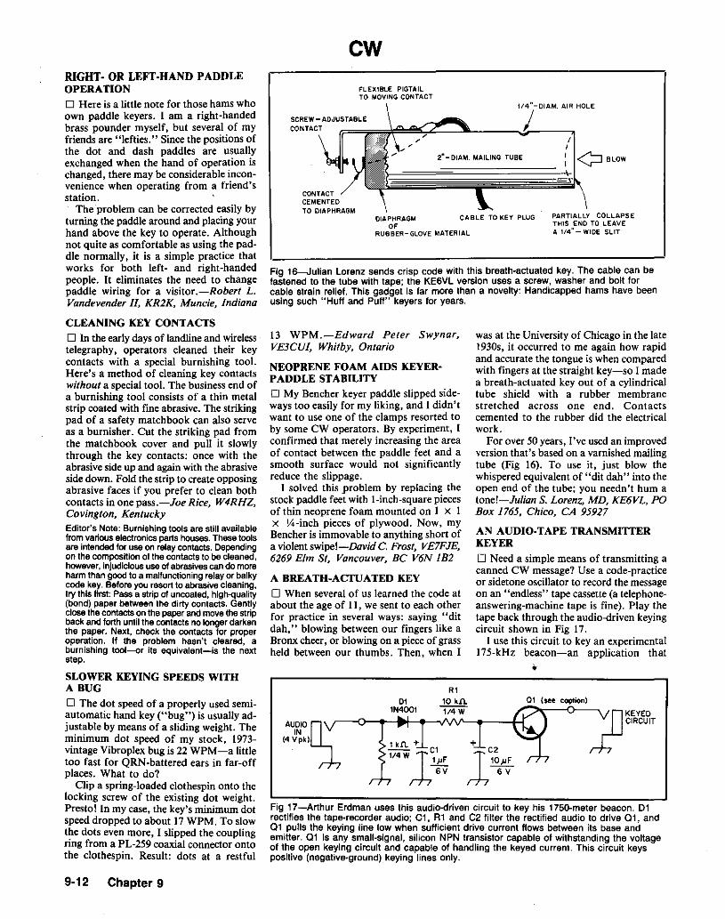
cwFLEXIBLE PIGTAILTO MOVING CONTACT
Fig 16---Julian Lorenz sends crisp code with this breath-actuated key. The cable can befastened to the tube with tape; the KE6VL version uses a screw, washer and bolt forcable strain relief. This gadget is far more than a novelty: Handicapped hams have beenusing such "Huff and Puff" keyers for years.
"2-0IA•. AIR HOLE
PARTIALLY COLLAPSETHIS END TO LEAVEA 1/4" - WIDE SLIT
2M_DIAM. MAILING TUBE
,, I1
: QBLOW
~~~DIAPHRAGM CABLE TO KEY PLUG
0'RUBBER-GLOVE MATERIAL
CONTACTCEMENTEDTO DIAPHRAGM
RIGHT- OR LEFT-HAND PADDLEOPERATION
D Here is a little note for those hams whoown paddle keyers. I am a right-handedbrass pounder myself, but several of myfriends are "lefties." Since the positions ofthe dot and dash paddles are usuallyexchanged when the hand of operation ischanged, there may be considerable inconvenience when operating from a friend'sstation.
The problem can be corrected easily byturning the paddle around and placingyourhand above the key to operate. Althoughnot quite as comfortable as using the paddle normally, it is a simple practice thatworks for both left- and right-handedpeople. It eliminates the need to changepaddle wiring for a visitor .-Robert L.Vandevender II, KR2K, Muncie, Indiana
Fig 17-Arthur Erdman uses this audio-driven circuit to key his 1750-meter beacon. 01rectifies the tape-recorder audio; Cl, AI and C2 filter the rectified audio to drive 01, and01 pulls the keying line low when sufficient drive current flows between its base andemitter. 01 Is any small-signal, silicon NPN transistor capable of withstanding the voltageof the open keying circuit and capable of handling the keyed current. This circuit keyspositive (negative-ground) keying lines only.
13 WPM.-Edward Peter Swynar,VE3CUI, Whitby, Ontario
NEOPRENE FOAM AIDS KEYERPADDLE STABILITY
D My Bencher keyer paddle slipped sideways too easily for my liking, and I didn'twant to use one of the clamps resorted toby some CW operators. By experiment, Iconfirmed that merely increasing the areaof contact between the paddle feet and asmooth surface would not significantlyreduce the slippage.
I solved this problem by replacing thestock paddle feet with l-inch-square piecesof thin neoprene foam mounted on 1 x 1x 'l'4-inch pieces of plywood. Now, myBencher is immovable to anything short ofa violentswipe!-David C. Frost, VE7FJE,6269 Elm sc Vancouver, BC V6N IB2
A BREATH-ACTUATED KEY
o When several of us learned the code atabout the age of II, we sent to each otherfor practice in several ways: saying "ditdah,' blowing between our fingers like aBronx cheer, or blowing on a piece of grassheld between our thumbs. Then, when I
CLEANING KEY CONTACTS
D In the early days of landlineand wirelesstelegraphy, operators cleaned their keycontacts with a special burnishing tool.Here's a method of cleaning key contactswithout a special tool. The business end ofa burnishing tool consists of a thin metalstrip coated with fine abrasive. The strikingpad of a safety matchbook can also serveas a burnisher. Cut the striking pad fromthe matchbook cover and pun it slowlythrough the key contacts: once with theabrasive side up and again with the abrasiveside down. Fold the strip to create opposingabrasive faces if you prefer to clean bothcontacts in one pass.-Joe Rice, W4RHZ.Covington. KentuckyEditor's Note: Burnishing tools are still availablefrom variouselectronics partshouses. Thesetoolsare intendedfor use on relaycontacts. Dependingon the compositionof the contacts to be cleaned,however, injudicioususeofabrasives cando moreharmthan goodto a malfunctioning relayor balkycode key. Beforeyou resort to abrasivecleaning,try this first: Passa strip of uncoated,high-quality(bond) paper between the dirty contacts. Gentlyclosethecontactson the paperandmovethe stripback and forth until the contactsno longerdarkenthe paper. Next, check the contacts for properoperation. If the problem hasn't cleared, aburnishing tool-or its equivalent-is the nextstep.
SLOWER KEYING SPEEDS WITHA BUG
o The dot speed of a properly used semiautomatic hand key ("bug") is usually adjustable by means of a sliding weight. Theminimum dot speed of my stock, 1973vintage Vibroplex bug is 22 WPM-a littletoo fast for QRN-battered ears in far-offplaces. What to do?
Clip a spring-loaded clothespin onto thelocking screw of the existing dot weight.Presto! In my case, the key's minimum dotspeed dropped to about 17WPM. To slowthe dots even more, I slipped the couplingring from a PL-259 coaxial connector ontothe clothespin.' Result: dots at a restful
'UOI0O;:IN(4.Vpkl
011N4001
1 k.n. +1I4wlC1lpF
6V
was at the University of Chicago in the lateI930s, it occurred to me again how rapidand accurate the tongue is when comparedwith fingers at the straight key-so I madea breath-actuated key out of a cylindricaltube shield with a rubber membranestretched across one end. Contactscemented to the rubber did the electricalwork.
For over 50 years, I've used an improvedversion that's based on a varnished mailingtube (Fig 16). To use it, just blow thewhispered equivalent of "dit dah" into theopen end of the tube; you needn't hum atone!-Julian S. Lorenz, MD, KE6VL, POBox 1765, Chico, CA 95927
AN AUDIO-TAPE TRANSMITTERKEYER
o Need a simple means of transmitting acanned CW message? Use a code-practiceor sidetone oscillator to record the messageon an "endless" tape cassette (a telephoneanswering-machine tape is fine). Play thetape back through the audio-driven keyingcircuit shown in Fig 17.
I use this circuit to key an experimental175-kHz beacon-an application that
•
9-12 Chapter 9
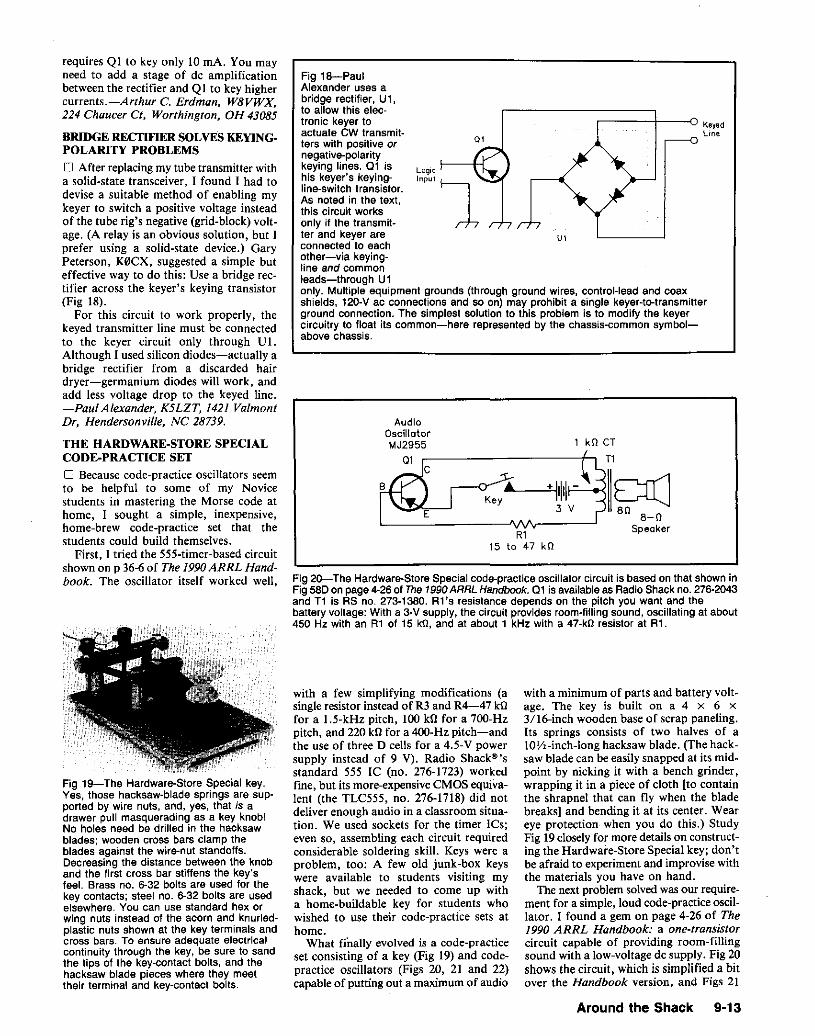
u,
with a minimum of parts and battery voltage. The key is built on a 4 X 6 x3/16-inch wooden base of scrap paneling.Its springs consists of two halves of alOY,-inch-long hacksaw blade. (The hacksaw blade can be easily snapped at its midpoint by nicking it with a bench grinder,wrapping it in a piece of cloth [to containthe shrapnel that can fly when the bladebreaks] and bending it at its center. Weareye protection when you do this.) StudyFig 19closely for more details on constructing the Hardware-Store Special key; don'tbe afraid to experiment and improvise withthe materials you have on hand.
The next problem solved was our requirement for a simple, loud code-practice oscillator. 1 found a gem on page 4-26 of The1990 ARRL Handbook: a one-transistorcircuit capable of providing room-fillingsound with a low-voltage de supply. Fig 20shows the circuit, which is simplified a bitover the Handbook version, and Figs 21
,-------;:::===:+---0 Keyedline
R115 to 47 kO
kO CT
T1
r-<Y"'~+ 11111+-=--+«IID(]-..;.:tlo(~..J 3 V 80 8- 0
Speaker
AudioOscillatorMJ2955
Q1 r---------I~
Fig l8-PaulAlexander uses abridge rectifier, U1,to allow this electronic keyer toactuate CW transmitters with positive ornegative-polaritykeying lines, 01 ishis keyer's keyingline-switch transistor.As noted in the text,this circuit worksonly if the transmitter and keyer areconnected to eachother-via keying-line and commonleads-through U1only. Multiple equipment grounds (through ground wires, control-lead and coaxshields, 120-V ac connections and so on) may prohibit a single keyer-to-transmitterground connection. The simplest solution to this problem is to modify the keyercircuitry to float its common-here represented by the chassis-common symbolabove chassis.
with a few simplifying modifications (asingle resistor instead of R3 and R4-47 kDfor a l.5-kHz pitch, 100 kll for a 700-Hzpitch, and 220 kll for a 4OO-Hz pitch-andthe use of three D cells for a 4.5-V powersupply instead of 9 V). Radio Shack@'sstandard 555 Ie (no. 276-1723) workedfine, but its more-expensive CMOS equivalent (the TLC555, no. 276-1718) did notdeliver enough audio in a classroom situation. We used sockets for the timer ICs;even so, assembling each circuit requiredconsiderable soldering skill. Keys were aproblem, too: A few old junk-box keyswere available to students visiting myshack, but we needed to come up witha home-buildable key for students whowished to use their code-practice sets athome.
What finally evolved is a code-practiceset consisting of a key (Fig 19) and codepractice oscillators (Figs 20, 21 and 22)capable of putting out a maximum of audio
Fig 20-The Hardware-Store Special code-practice oscillator circuit is based on that shown inFig 580 on page 4-28 of The 1990 ARRL Handbook. Q1 is available as Redia Shack no. 276-2043and T1 is RS no. 273·1380. R1's resistance depends on the pitch you want and thebattery voltage: With a 3-V supply, the circuit provides room-filling sound, oscillating at about450 Hz with an R1 of 15 kO, and at about 1 kHz with a 47-kO resistor at R1.
Fig 19-The Hardware-Store Special key.Yes, those hacksaw-blade springs are supported by wire nuts, and, yes, that is adrawer pull masquerading as a key knob!No holes need be drilled in the hacksawblades; wooden cross bars clamp theblades against the wire-nut standoffs.Decreasing the distance between the knoband the first cross bar stiffens the key'sfeel. Brass no. 6-32 bolts are used for thekey contacts; steel no. 6-32 bolts are usedelsewhere. You can use standard hex orwing nuts instead of the acorn and knurledplastic nuts shown at the key terminals andcross bars. To ensure adequate electricalcontinuity through the key, be sure to sandthe tips of the key-contact bolts, and thehacksaw blade pieces where they meettheir terminal and key-contact bolts.
requires Q I to key only 10 rnA. You mayneed to add a stage of de amplificationbetween the recti fier and Q I to key highercurrents.-Arthur C. Erdman. W8VWX.224 Chaucer ci, Worthington, OH 43085
BRIDGE RECI1FIER SOLvEs KEYINGPOLARITY PROBLEMS
o After replacing my tube transmitter witha solid-state transceiver, I found I had todevise a suitable method of enabling mykeyer to switch a positive voltage insteadof the tube rig's negative (grid-block) voltage. (A relay is an obvious solution, but Iprefer using a solid-state device.) GaryPeterson, K0CX, suggested a simple buteffective way to do this: Use a bridge rectifier across the keyer's keying transistor(Fig 18).
For this circuit to work properly, thekeyed transmitter line must be connectedto the keyer circuit only through U1.Although I used silicon diodes-actually abridge rectifier from a discarded hairdryer-germanium diodes will work, andadd less voltage drop to the keyed line.-Paul Alexander, K5LZT, 1421 ValmontDr, Hendersonville, NC 28739.
THE HARDWARE-STORE SPECIALCODE·PRACTICE SET
o Because code-practice oscillators seemto be helpful to some of my Novicestudents in mastering the Morse code athome, I sought a simple, inexpensive,home-brew code-practice set that thestudents could build themselves.
First, I tried the 555-timer-based circuitshown on p 36-6of The 1990ARRLHandbook. The oscillator itself worked well,
Around the Shack 9·13

Fig 21-The solderless Hardware-StoreSpecial code-practice oscillator. Most of itsconnections are made with crimp-on terminals-admittedly for a wire size a bit larger thanthat of the circuit's componentsl Wire nutscomplete the connections to 01's base andemitter leads. The spherical speaker Is ajunk-box item; any 8-0 speaker will do.Standard nuts and bolts can be used insteadof the knurled key~terminal nuts.
Fig 22-This Hardware-Store Special codepractice oscillator requires some soldering. Inthis version, Rl consists of a 5-kO resistorin series with a SO-kO potentiometer, used asa variable resistor, for pitch control. The pushbutton "key" makes this Hardware-StoreSpecial self-contained, and convenient forpaired groups in a classroom.
....70 ['J
Pins 3 and 6 are unused
U.MCT-2
Optolsolotor
5
to
pin 8 !------:;;~__.!t,---'lN\r------( +B VOf V12B \In HW-101
and 22 show two implementations of thecircuit. The oscillator shown in Fig 21 issolderless; its connections are made withcrimp-on lugs and wire nuts.
Now my Novice students are buildingtheir own keys and code-practice setsthemselves-at minimum cost, and withcommonly available parts and tools.-ArtZavarella, W1KK, 1702Main St, Agawam,MA 01001
TEAMING THE W60WP KEYINGINTERFACE WITH THE HEATHKITHW·IOI TRANSCEIVERo In April 1987 QST,6 F. A. Bartlett,W60WP, described a circuit capable ofeliminating first-character distortion(shortening) that occurs during semi-breakin (keyed VOX) CW operation with sometransceivers. reaming the circuit with myHeathkit" HW·10I involved a few modifications that may be of interest to otherswho intend to use the interface with older,tube-based transceivers. Here's how Imodified the two to work together.
Fig 23 shows the additional circuitry
SF. Bartlen, "A CWKeying Interface," OST, Apr1987, pp 51-53.
Fig 23-J1 m Zvolanek modified F. A.Bartlen's CW keying interface for compatibility with a Heathkit HW-l01 transceiver asshown at A. New power-supply circuitry (B),powered by the HW-l01 's 12.6-V ac heatersupply, was necessary, too. Resistors are1/4-W. carbon-film units. See text.
9-14 Chapter 9
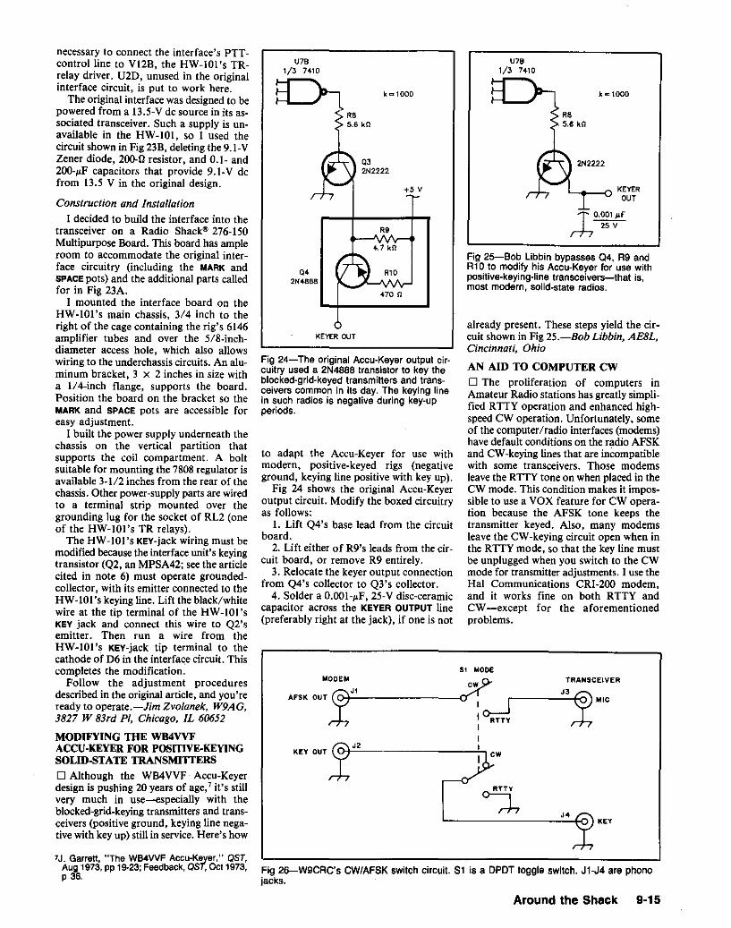
k"'1000
KEY
T 0.001 JJ.f
,;, 25 V
L.......--<J KEVEROUT
R.5.6 kQ
J'
U7.1/3 7410
AN AID TO COMPUTER CW
o The proliferation of computers inAmateur Radio stations has greatly simplified RTTY operation and enhanced highspeed CW operation. Unfortunately, someofthe computer/radio interfaces (modems)have default conditions on the radio AFSKand CW-keying lines that are incompatiblewith some transceivers. Those modemsleave the RTTY tone on when placed in theew mode. This condition makes it impossible to use a VOX feature for CW operation because the AFSK tone keeps thetransmitter keyed. Also, many modemsleave the CW-keying circuit open when inthe RTTY mode, so that the key line mustbe unplugged when you switch to the CWmode for transmitter adjustments. I use theHal Communications CRI-2oo modem,and it works fine on both RTTY andCW-except for the aforementionedproblems.
already present. These steps yield the circuit shown in Fig 25.-Bob Libbin, AE8L,Cincinnati. Ohio
Fig 25-Bob Libbin bypasses 04, R9 andR10 to modify hiS Accu-Keyer for use withpositive-keying-Iine transceivers-that is,most modern, solid-state radios.
~KEY OUT~
Sl MODEMODEM
xJ1cw..$' TRANSCEIVER
AFSK OUT -:..-------~(7""1 r ....:J::3~- I o---J MIC
I RnyIII
U7B1/3 7410
k""1000
R85.8 kCl
Q32N2222
+5 v
R9
4.7 kO
Q' R102N4888
470 n
KEVER OUT
Fig 26-W9CRC's CW/AFSK switch circuit. Sl is a OPOT toggle switch. Jl-J4 are phonolacks.
to adapt the Accu-Keyer for use withmodern, positive-keyed rigs (negativeground, keying line positive with key up).
Fig 24 shows the original Accu-Keyeroutput circuit. Modify the boxed circuitryas follows:
I. Lift Q4's base lead from the circuitboard.
2. Lift either of R9's leads from the circuit board, or remove R9 entirely.
3. Relocate the keyer output connectionfrom Q4's collector to Q3's collector.
4. Solder a O.()()I-~F, 25-V disc-ceramiccapacitor across the KEVER OUTPUT line(preferably right at the jack), if one is not
Fig 24-The original Accu-Keyer output circuitry used a 2N4888 transistor to key theblocked-grid-keyed transmitters and transceivers common in its day. The keying linein such radios is negative during key-upperiods.
necessary to connect the interface's PTTcontrol line to VI2B, the HW-IOI's TRrelay driver. U2D, unused in the originalinterface circuit, is put to work here.
The original interface was designed to bepowered from a 13.5-V de source in its associated transceiver. Such a supply is unavailable in the HW-IOt, so I used thecircuit shown in Fig 23B, deleting the 9.I-VZener diode, 200-0 resistor, and 0.1- and2()()-~F capacitors that provide 9.1-V defrom 13.5 V in the original design.
Construction and Installation
I decided to build the interface into thetransceiver on a Radio Shack" 276-150Multipurpose Board. This board has ampleroom to accommodate the original interface circuitry (including the MARK andSPACE pots) and the additional parts calledfor in Fig 23A.
I mounted the interface board on theHW-IOI's main chassis, 3/4 inch to theright of the cage containing the rig's 6146amplifier tubes and over the 5/8-inchdiameter access hole, which also allowswiring to the underchassis circuits. An aluminum bracket, 3 x 2 inches in size witha 11a-inch flange, supports the board.Position the board on the bracket so theMARK and SPACE pots are accessible foreasy adjustment.
I built the power supply underneath thechassis on the vertical partition thatsupports the coil compartment. A boltsuitable for mounting the 7808 regulator isavailable 3-112 inches from the rear of thechassis. Other power-supply parts are wiredto a terminal strip mounted over thegrounding lug for the socket of RL2 (oneof the HW-IOI's TR relays).
The HW-lOl's KEY-jack wiring must bemodified because the interface unit's keyingtransistor (Q2, an MPSA42; see the articlecited in note 6) must operate groundedcollector, with its emitter connected to theHW-IOI 's keying line. Lift the black/whitewire at the tip terminal of the HW-IOI'sKEY jack and connect this wire to Q2'semitter. Then run a wire from theHW-IOI's KEY-jack tip terminal to thecathode of D6 in the interface circuit. Thiscompletes the modification.
Follow the adjustment proceduresdescribed in the original article, and you'reready to operate.-Jim Zvolanek, W9AG,3827 W 83rd PI, Chicago, IL 60652
MODIFYING THE WB4VVFACCU-KEYER FOR POSITIVE-KEYINGSOLID-STATE TRANSMITIERS
o Although the WB4VVF Accu-Keyerdesign is pushing 20 years of age;" it's stillvery much in use-especially with theblocked-grid-keying transmitters and transceivers (positive ground, keying line negative with key up) still in service. Here's how
7J. Garrett, "The WB4WF Accu-Keyer," QST,Aug 1973, pp 19-23; Feedback, QST, 0011973,P 36,
Around the Shack 9-15

Fig 27-John Swancara's RS-232-C-to-keying-tine interface consists of just four parts. Youcan build the circuit on a piece of scrap copper-clad circuit board. John obtained U1, aT1L-111 optocoupler, as part of Radio Shack's 276-139 optocoupler assortment.
to PositiveKeying Line
OUTPUT
Pin 3is unused
.....__~ to TransmitterChassis
NC
llL-1111 5
so far down that it causes no problems.I suggest keeping the resonant speaker
in the clear by at least 2 feet. Place it ona soft pad. I use a hemostat to adjust theposition of the tuning plug. On some of thespeakers, two positions of the slug producea peak-one at the open end of the tube,and another about half-way down towardthe speaker. From using both positions onthe air, I think the inner position may bebest.
I drive the speaker from my Ten-TeeOmni's rear-panel PHONE PATCH jack,turning off the regular speaker with aswitch. Slow tuning is essential, because thesharpness of the speaker peak can causeyou to overlook signals of weak tomoderate strength if you tune tooquickly.-Wally Millard, K4JVT,Camden, North Carolina
Editor's Note: I'm uncertain as to what formulaK4JVT used to calculate the length of hisresonator. According to J. E. Williams, F. E.Trinkleinand H. C. Metcalf,ModemPhysics(NewYork: Holt, Rinehart and Winston, 1976),p 273,the formula for resonance of a closed tube is
1 kO1/4 Wfrom
RS-232-C 1--.....---'VV'v----j..-...JOTR
0.01 I"F
Co~~~terr-f 50 VChassisGround
from
RS- 232-C J----------::::l..!.._..;~=_---(Signal \
GroundINPUT
Fig 28-K4JVT's resonant speaker for CW,cut for 750 Hz. The closed-tube resonatorconsists of 2-inch-OD PVC pipe, 5% incheslong. The 2-inch speaker (out of view at thefar end of the resonator) is mounted to thepipe with electrical tape. The tuning plug is1·1/8-inch-diameter wooden dowel, 1-1/4inches long; its positioning fins are thinaluminum stock, press fit into transverseslits in the dowel. The short wire visible atthe speaker end of the tube is one of thespeaker connections. The speaker stand isheavy-gauge aluminum wire.
Here is a cure for these problems. It consists of an external DPDT switch, a smallaluminum box and four phono jacks.
Fig 26 shows my switching arrangement.When the toggle is in the CW position, themodem AFSK/transmitter circuit is openedand the CW-keying circuit is completed.When the toggle is in the SSB position (forRTTY operation). the AFSK circuit is completed and the CW-keying circuit isgrounded (to key the transmitter when itis placed in the CW mode).
This external switch allows easy changeover between AFSK and CW modes without the need for internal modem modifications. The project is very easy to build,and it makes computer CWIRTTY operation much more convenient.-RussRennaker, W9CRG, Kokomo. Indiana
CHEAP AND QUICK RS-232-C-TO·KEYING-LINE INTERFACE
o While experimenting with my Tandy"1000 home computer and some ham codegeneration programs, I learned that thecomputer's RS-232MC DTR line switchedfrom + 14 to -14 V when the programs executed the code. In about 1 hour, with a fewRadio Shack" parts, 1 built the interfaceshownin Fig27. It worksgreatand easilykeysmy transceiver. I now send perfect CW!
When the Tandy 1000's + 14/ -14-VRS-232-C DTR signal switches to -14 V.the optocoupler's LED turns on the output transistor, pulling the circuit's OUTPUTline low. If you need a circuit that goes lowon positive excursions of the INPUT line,just reverse the IN914, and the connectionsto pins 1 and 2 of the optocoupler. If keyingyour rig involves switching a higher voltagethan the optocoupler can handle, you cancontrol a dc relay with the optocoupler andkey the rig with the relay. 8-JohnSwancara, WA6LOD, 1002 E MariposaAve, EI Segundo, CA 90245
wheref = length of the closed tube in inchesf = resonant frequency of the tube in hertzd = inner diameter of the tube in inches.
where}.. = wavelength of the tube's fundamental
resonant frequency£ = length of the tubed = tube diameter
Assuming that the speed of sound in 250 C airis about 13,622inls, this formulacan be rewrittento sotve for eas
1 ~ 3406 -04d Eq 2f .
The innerdiameter of thePVCpipe shown in Fig28is 1.56 inches. With this value for d, solving Eq 2for f = 750givesa tube lengthof 3.9 inches.Thisis considerably shorter than K4JVT's resonator.On the other hand, the graph in S. L. Seaton,"A ResonantLoud-Speaker for C.W. Reception."QST, May 1936, p 64, indicates that a closedtube resonator for 750 Hz should be about4.3 inches long. Seaton states that "A pipediameter of two to four inches is suitable forordinary frequencies." Clearly, there's plenty ofroom for cut-and-try experimentationl
aFar an all-solid-state solution, see J. Galm,"Simple Control-Signal Level Converters,"in the Feb 1990 QST, pp 24-27.
A RESONANT SPEAKER FOR CW
o Some years back. QST published anarticle on building a resonant speaker forCW. 9 I tried it, but the results were disappointing. That speaker required a glasstumbler of a certain size, and I couldn'tclosely duplicate it.
I decided to build a closed-tube resonator based on a formula in myoid collegephysics book. I felt that the frequencyresponse of speakers more than 2 inches indiameter would be too wide, so I settled ona 2-inch replacement speaker (Radio Shack40-245). An empty plastic caulking tubewas available, so I cut it to length for750 Hz. Then I taped the speaker to oneend of the tube with electrical tape. During
9J.B. and A. V. Heaton,"An Electro-Acoustic CWFilter." QST, Apr 1983, pp 35-36.
9-16 Chapter 9
its first trial, the speaker exhibited apronounced peak, but I wasn't satisfiedwith its output. As I picked up the speaker, however, I happened to put my thumbinside the tube. To my surprise, the output went up!
To investigate this effect, I installed amovable wooden plug in the tube. Transverse slits in the plug hold fins of thin aluminum stock; these fins can be shaped tocenter the plug in the pipe. Experimentation consisted of trying the speakerwith the plug at various depths in the pipe.Thinking that stiffer resonator materialmight improve speaker efficiency, I builttwo more resonators from 2-inch OD PVCpipe (see Fig 28). The results are inconclusive, but each speaker produces a useful peak at 750 Hz. On the average, outputat the peak is about 4 to 7 dB over the freeair response of the speaker. I can detectanother peak at about 440 Hz, but this is
, = 4 (I + O.4d) Eq 1

:0 TVO';T.,T,.
~~J--__-+---Iul[, SPK.I A'SIGNAL ISOURCE
air resonance shifts when the speaker iscoupled to the pipe, so some fine tuning ofthe speaker tuning capacitors will probablybe required. (Adjustment of the pipe lengthmay also be necessary, so make the pipelonger than necessary to start with.)
I suggest using resonant speakers atpitches between 300 and 400 Hz because theear is logarithmic in sensing volume andpitch. QRM at 700 Hz is about a whole stepremoved from a desired signal at 800 Hz,but almost halfan octave removed at signaland QRM pitches of 300 and 200 Hz,respectively. Thus, lower received-signalpitches generally allow the ear to do a betterjob of distinguishing adjacent signals fromone another.
By the way, graphic equalizers can alsobe used for tailoring audio response.Boosting a desired pitch and attenuating allother frequencies produces a well-definedpassband. A stereo equalizer with bothsections connected in series should providemore than adequate audio selectivity forgeneral communication purposes.-JimWeiss, W9ZMV, cia WTAQ, La Grange,1L 60525
IBI
IAI
C
SIJ~AL II---------1===nJSPKRSOURCE. _
ANDVOL TMETER
Fig 30-A setup for determining speakerresonance is shown at A. A (5 to 10 0)may be necessary for isolation between theaudio source and tuned speaker. Speakerresonance is indicated by a voltmeter peak.Jim Weiss suggests enhancing thespeaker's free-air resonance by means of aseries capacitor or capacitors (B); if you dothis, use your receiver or transceiver as anaudio source to ensure that thecapacitance selected allows for the effectsof the rig's audio-output circuitry.
_____ PENNIES
assembly as such will fail. Instead ofaltering the length-to-diameter ratio witha plug, using a smaller-diameter pipeshould give a sharper resonance. (Considerthe length-to-diameter ratio of organ pipesas a good starting point; their proportionsare similar to those of a pencil.)
The 44O-Hz peak Wally Millard heardmay have been the speaker's free-airresonance (as modified by the presence ofthe resonant tube), which can be determined with the setup shown in Fig 30A.Matching the pipe length to the speaker'sresonance will improve performance. Acapacitor can be added to series-resonatethe speaker inductance for an even sharperresponse (Fig 30B). This requires cut andtry; use nonpolarized capacitors,paralleling capacitors of different values asneeded.
For optimum results with a resonantspeaker, especially at slower code speeds,I suggest using a tiny speaker resonating at300 to 400 Hz (tune the speaker with acapacitor to accentuate the speaker'snatural resonance). Once the speaker hasbeen tuned, find the pipe length thatmatches the speaker's resonance and mountthe speaker to the pipe. The speaker's free-
Fig 29-Richard Clemens increased thesharpness of his resonant speaker's peakby upending the tube and supporting thetube on three pennies. This also decreasesthe assembly's resonant frequencysomewhat; see text
NOTES ON RESONANT SPEAKERSFOR ENHANCED CW RECEPTION
o Resonant columns are somewhat likeantennas: Short, fat pipes are low-Q, likecage or cone antennas; long, thin pipes arehigh-Q resonators. (Trying to use aresonant column as a sound generator cangive you an idea of the importance of"acoustical Q" in a resonator: Blowingacross a pop bottle produces a fairly welldefined tone with many overtones, like aflute. Producing any sort of tone with apop can is difficult.)
A fat tube with a speaker in the end isnot exactly a closed pipe, so formulas thatattempt to characterize a speaker-tube
MORE ON RFSONANT SPEAKERS
o I read with interest the article by WallyMillard, K4JVT, concerning theconstruction of a resonant speaker for CW.Using the editor's note that accompaniedWally's article, I decided on a four-inchlong piece of PVC that has an ID of 42 mm(1-518 inches). I mounted a 2-inch-diamspeaker (Radio Shack~ 40-245) to one endof the tube with electrical tape as suggestedby K4JVT.
In order to test the resonance of thesystem, my son wrote a program inMicrosoft'" BASIC 3.0 for the Macintoshcomputer. This program allows me tomodify and display the frequency of thetones produced at the speaker port. Usingthe Macintosh to drive the speaker system,a noticeable increase in volume wasapparent at 870 Hz.
With some further experimentation, Ifound that an even stronger peakoccurred-at a frequency somewhat lowerthan that of the open-ended tube-whenthe tube is placed open end down on a hardsurface with a small space between the tubeand supporting surface. Currently. I amsupporting the tube on three pennies(Fig 29). This provides maximum output at670 Hz-approximately 200 Hz lower thanthe "wide open" tube.
This project is very easy to construct, andis certainly worth the few dollars ofinvestment needed for the parts. Any CWenthusiast should enjoy the result.-Richard Clemens, KB8AOB, 103Barbour St, Buckhannon, WV 26201
Around the Shack 9-17

PACKET
P2 TNC
2 5
o 0o 0 0 0
1 MIl.
PTT
TNC AFSK out
RESET 4
VOICE
sounds until the l000-J'F capacitor ischarged (about 3 seconds). Pushing SI(ALARM) to RESETtOFF disables the alarmand discharges the capacitor through the470-0 resistor. Except for the buzzer, allof the components mount on a PC board(mine is about 1~ inches square) solderedto the terminals of St.-AI Smardon,VE30X, RR E, Carrying Place, ON KOK1LO, Canada
TIMER
51ATNC audio in
J2 J3AUDIO IN SPEAKER
1N914
r--~-----!'~ OUTPUT
PIMIC
5
M B 1,000,000
JlXCVRMIC
INPUT
TO CATHODE (}-~__ '_.....-+-'21 TRIGGER -vce~·'--'4---0+OF CR19 r 5·1211DC
IN MFJ-1270 {CONNECT TOr---o - LEADS OF Ct2~ IN MFJ-t210 I
Fig 31-Robert Dingle built this circuit to allow easy switching between .voice and packetradio operation with his VHF transceiver. J1 and P1 complement t.he rruc connectors .usedon the transceiver; your installation may require connectors of ~ different type, and ~m
number assignments may differ from those shown here. Any mlcrophone-Conne?tor linesnot affected by packet/voice switch (pins 3, 4 and 6 in this cas~) should be car.ned fromJ1 to P1 to preserve the functions they support. 51 can be a slide or rotary sWI~c.h. Theconnector types used at J2, J3 and P2, and the pin assignment at P2, are uncritical andcan vary with the connectors available.
Ul,..
Fig 32-The K4HCDIWA4NFK connect-alarm circuit. CR19 is MFJ's nomenclature for theCONNECT LED on the MFJ-1270 TNC. Its cathode lead is to the left as viewed from thefront of the TNC. Resistors are V4-W, carbon film. The 0.01· and 0.47-p.F capacitors maybe ceramic or plastic film; the 1-p.F capacitor is a tantalum electrolytic. LS1 is a piezoelectric buzzer.
0.47 )JF
470.n.
A TNC CONNECT ALARM
o Missing a contact on packet by failingto see or hear a connect can be frustrating.To solve this problem on my GLB TNC,I added the circuit shown in Fig 34. Whenthe CONNECT LED comes on, the buzzer
-Frederick D. Losch, KA9CCZ, RR#4,Box 207, Winchester, EN 47394
A SWITCH BOX FOR VOICE ORPACKET RADIO
o Have you joined the ranks of VHFpacketeers? Unless you have a VHF transceiver dedicated to packet-radio operation,you've probably discovered that switchingbetween voice and packet operation is inconvenient because of the different audiofeeds necessary for these modes. The simpleswitch box shown in Fig 31 can allow youto enjoy both modes with a minimum ofbother.
J 1 must be the same as the connector onthe transceiver mic; PI must mate with thetransceiver's microphone connector. I useda male DB9 connector (Radio Shack" no.276-1537) at P2, TNC. In my installation,12, AUDIO IN, carries audio obtained fromthe transceiver's external speaker jack, and13 carries audio to the external speakerwhen voice operation is selected. I used athree-pole, double-throw push-buttonswitch at Sl ; a rotary switch would workfine, too.
Because the switch-box componentsaren't heavy, I mounted my switch box tothe side of the TNC with one of the TNC'scover-mounting screws. With the TNCserving as ballast, the switch box doesn'tmove when I push S I.
Most recent MF/HF transceivers includerear-panel connections for PTT, AFSKinput and audio output. Such auxiliaryaudio I/O connections need not bedisturbed for voice operation. MF/HFtransceivers without separate audio I/Oconnections suitable for digitalcommunications can benefit from theaddition of a switch box like that describedhere.-Robert L. Dingle, KA4LA U, 657Dell Ridge Dr, Dayton, OH 45429
A TNC CONNECT ALARM
o We wanted an audible alarm for ourMFJ-1270TNCs so we'd know when someone connected to our packet-radio stations.Solution: The simple alarm circuit shownin Fig 32. The alarm uses a 555 timer IC(connected as a one-shot multivibrator) todrive a piezoelectric buzzer when the TNC'sCONNECT LED lights. Only eight components are used, including the ICj inaddition, we used IC sockets and RadioShack" dual Ie hoards (RS 276-159) tohold the components. Layout is notcritical.-George Kammerer, K4HCD,Charleston Heights, and Pat McLeod,WA4NFK, Ladson, South Carolina
IMPROVING THE TNC CONNECTALARM
o K4HCD's Hint shows a very timelyTNC-connect-alarm circuit. My version ofthe connect alarm did not trigger reliably,so I modified the circuit as shown inFig 33. Now, it works every time.
9-18 Chapter 9

470.0.
(A)
Fig 33-Frederick Losch's TNC connectalarm didn't always sound the alarm whenhis TNC connected, so he modified part ofthe original circuit (A) as shown at B.Frederick further reports that the 555'sability to drive more than one piezoelectricbuzzer can be put to good use when multiple alarm buzzers are desired (one at theTNC and another at a remote location, forinstance). He cautions, however, thatelectromagnetic transients picked up bylong buzzer wires can cause false triggering of the alarm.
5-12VDC(CONNECT TOLEADS OF Cl2IN MFJ-1270)
+
+5-IZVDC
100 en
lN914
y
4?On..
lN914- If--<.2- •.... TRIGGER e vcc
O.01.llF
1~=toool555 - ,
O.47J.lF
" 2 •I II I TRIGGER + vee
lI"'T 555t,
TO CATHODEOF CRI9
IN MFJ-IZ70
TO CATHODEOF CR19
IN MFJ -1270
(B)
A TNC MESSAGE-WAITINGALERTERo After recently becoming active in packetradio, I almost immediately became
frustrated with having to connect myTandy" 102computer to the TNC to see ifany messages had been left for me. BecauseI'm not in the shack most of the day, anaudible alarm would have been most trying for my wife. Thinking there must be abetter way, I decided to try an approachused in hotel and motel telephone systems.
My solution (Fig 36), a TNC messagewaiting circuit. uses exactly the samenumber of parts as K4HCD's audiblealarm. It automatically indicates that amessage has been left in the TNC, andautomatically resets when the message isdelivered to the local terminal. The TNCoperates normally all the time. except whenthe local terminal interface has been"turned off" with the XOFF commandcharacter (usually Control-S). When theTNC is in XOFF mode and a remote station connects, the TNC stores receiveddata. When the operator returns the TNCto the XON mode, the TNC responds bysending the message to the local terminal.If a station leaves a message at the TNCwhile it's in XOFF mode, the CONnectLED flashes(0.5 second on, 0.5 second oft)after the station disconnects and until themessage is delivered to the local terminal.The flashing CON LED gives the operatora visual indication that the connectoccurred, and that a message is probablywaiting for him. I built the prototypeversion on a l-inch-square piece of"experimenter's" PC board in about anhour; part placement and layout are notcritical.
The CircuitThe message-waiting alerter uses both
timers in a 556 dual-timer Ie to monitorthe status of a connect within the TNC. Thefirst timer (VIA) is configured as an RSflip-flop, using active-low inputs. Thesecond timer (U1B) serves as an astable
Around the Shack 9·19
12 V
470 n
51ALARM
+
L51
PlezoeletrlcBuzzer
1000 ~f
1S V
+
4700
1/4 W
ALARMRESET/OFF
ENABLE
functions as a logic inverter; the secondsinks current from the alarm buzzer. Asingle PNP transistor (2N3906) can function as a logic inverter and current sink forthe buzzer, as shown in Fig 35.-Paul B.Christensen. N9AZ, Jacksonville, Florida
10 kO
2N3906
10 k n
12V
k=1000
toCON LEDCathode
Fig 35-Paul Christensensimplified AI Smardon'sGLB TNG-alarmcircuit byusing a single PNPtransistor instead of twoNPNs.
Fig 34-AI Smardonadded this connectalarm to his GLB TNC.LS1 is a RadioShack" 273-055buzzer.
SIMPLIFYING THE OCTOBER 1990GLB TNC MESSAGE-ALERT ALARMo VE30X provided a circuit for interfacing a connect alarm to a OLB terminalnode controller (TNC). Although the circuit will work well as shown, nearly halfof its circuitry can be eliminated throughthe use of a PNP transistor instead of twoNPNs.
The first 2N3904 in the original design
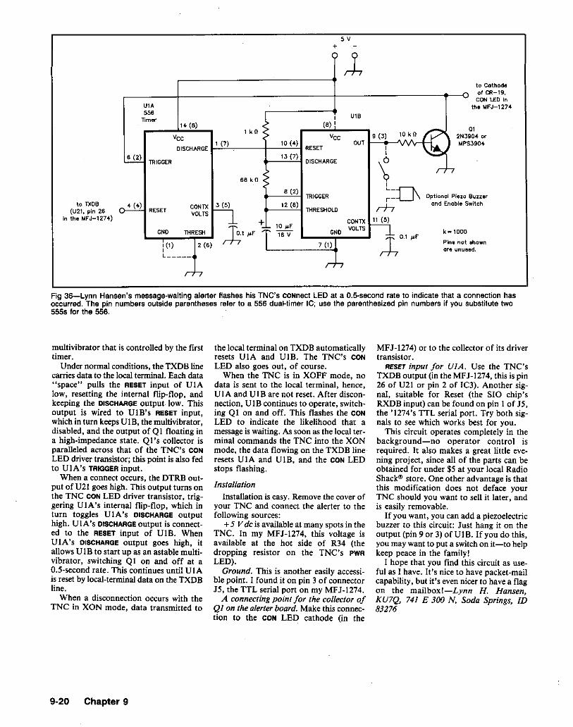
5V+
to Cathodeof CR-19,CON 1.£0 In
the MFJ-1274
Buzzerwitch
0104 ~3904
shown.d.
1UI.556 U1B
Timer I14- (8)
1 kO ::-(8) !
10kAO
PVee Vee 9 (3) ) 2N39I (7) 10 (4) OUT
v ~"PS
DISCHARGE RESET I
13 (7)I
!B. TRIGGER DISCHARGE \6B kO <: r7
8 (2)L_nTRIGGER r- Optional Pleac
4 (4)eONTXn 12 (6) rh
and Enable 5RESET
VOLTSTHRESHOLD
~ CONTX PiONO THRESH ~1 ~f ;~ 10 _F
ONOveLTS k .. 100016 V
,-L0" _Fi (1) 7 (1) Pinll not2 (6)ore unuaL_____
r:"J,
to TXDB(U21, pin 26
In the MfJ-1274)
Fig 36-Lynn Hansen's messagsMwaiting alerter flashes his TNC's CONnect LED at a n.s.secono rate to indicate that a connection hasoccurred. The pin numbers outside parentheses refer to a 556 dual-timer Ie; use the parenthesized pin numbers if you substitute two5555 for the 556.
multivibrator that is controlled by the firsttimer.
Under normal conditions, the TXDB linecarries data to the local terminal. Each data"space" pulls the RESET input of UIAlow, resetting the internal flip-flop, andkeeping the DISCHARGE output. low. Thisoutput is wired to UIB's RESET input,which in turn keeps UIB, the multivibrator,disabled, and the output of QI floating ina high-impedance state. QI's collector isparalleled across that of the TNC's CON
LED driver transistor; this point is also fedto UlA's TRIGGER input.
When a connect occurs, the DTRB output of V21 goes high. This output turns onthe TNC CON LED driver transistor, triggering UIA's internal flip-flop, which inturn toggles UIA's DISCHARGE outputhigh. UIA's DISCHARGE output is connected to the RESET input of VIB. WhenUIA's DISCHARGE output goes high, itallows VIB to start up as an astable multivibrator, switching QI on and off at aO.5-second rate. This continues until UIAis reset by local-terminaldata an the TXDBline.
When a disconnection occurs with theTNC in XON mode, data transmitted to
the local terminal on TXDB automaticallyresets VIA and VIB. The TNC's CON
LED also goes out, of course.When the TNC is in XOFF mode, no
data is sent to the local terminal, hence,UIA and UIB are not reset. After disconnection, UIB continues to operate, switching QI on and off. This flashes the CON
LED to indicate the likelihood that amessageis waiting. As soon as the local terminal commands the TNC into the XONmode, the data flowing on the TXDB lineresets VIA and VIB, and the CON LEDstops flashing.
InstallalionInstallation is easy. Remove the cover of
your TNC and connect the alerter to thefollowing sources:
+5 V de is available at many spots in theTNC. In my MFJ-1274, this voltage isavailable at the hat side of R34 (thedropping resistor on the TNC's PWR
LED).Ground. This is another easily accessi
ble point. I found it on pin 3 of connectorJ5, the TTL serial port on my MFJ-1274.
A connecting point for the collector ofQl on Ihe aterterboard. Make this connection to the CON LED cathode (in the
MFJ-1274) or to the collector of its drivertransistor.
RESET input for UIA. Use the TNC'sTXDB output (in the MFJ-1274, this is pin26 of V21 or pin 2 of IC3). Another signal, suitable for Reset (the SIO chip'sRXDB input) can be found on pin I of J5,the '1274's TTL serial port. Try bath signals to see which works best for you.
This circuit operates completely in thebackground-no operator control isrequired. It also makes a great little evening project, since all of the parts can beobtained for under $5 at your local RadioShackw store. One other advantage is thatthis modification does not deface yourTNC should you want to sell it later, andis easily removable.
If you want, you can add a piezoelectricbuzzer to this circuit: Just hang it on theoutput (pin 9 or 3) of VI B. If you do this,you may want to put a switchon it-to helpkeep peace in the family!
I hope that you find this circuit as useful as I have. It's nice to have packet-mailcapability, but it's even nicer to have a flagon the mailbox!-Lynn H. Hansen,KU7Q, 741 E 300 N, Soda Springs, ID83276
9-20 Chapter 9

CHAPTER 10
ElectrolllagneticInterference (RFI/EMI)_-
Fig 2-Jim Rafferty's addition to H & K's anti-Tv! arsenal: Inserting two transformers anda 300-{} filter in a 75M
{} TV antenna system quashes RFI caused by shield-borne HFenergy.
relatively high reactance (at ham frequencies below 30 MHz) of the capacitors inseries with the TV transmission line.
Open the filter case (usually plastic) andbreak the connection between the input andoutput inductors. Be sure there is no depath between the coils. Complete themodification by closing the filter case. (Ifthe case breaks, a little tape and glue canrepair it.}
Try the filter and note the results. If theinterference lessens, fundamental overloadis at least part of the cause. If the improvement is substantial but not complete, trycascading two modified filters.-JamesPentland, K03D, York, Pennsylvania
11!5-nCOAX
TOTVr--:-""'I, SET
300- TO1!5-nBALUN
transformers and filters are available fromRadio Shack'", TV dealers, electronicsstores and similar sources.-Jim Rafferty,N6RJ, 5693 Grandview, Yorba Linda, CA92686AK7M: In addition to offering an obstacle toshield-conducted HF energy by breaking thecoax shield, this transformer-fijter-transformerfix may owe part of its success to inefficiencyof the 75-toM300M
{} transformers at HF.
MORE ON CURING TVI WITH 300-llFILTERS AND 4:1 TRANSFORMERS
D Jim Rafferty, N6RJ, reported curingTVl in 75-ll systems with 300-ll high-passfilters and 4: I transformers. This cure hasbeen making the rounds in many of the6-Land newsletters for several years. Itworks, and I have been investigating whyit works. After all, a 75-ll high-pass filtershould work fine in 75-0 cable!
The only reason an effective 75-0 filtermay not work in a 75-0 coaxial-cablesystem is that a common-mode signal exists. (A common-mode signal travels downcoax, particularly on the outside of thecoax braid, as if the coax is just one wireof a two-wire circuit.) If coax is doing itsjob, the RF currents on its center conductorand shield wire are of the same magnitudebut opposite in phase. When this is so, thecoax acts like the transmission line it is,providing source and return paths for thesignals it carries. Cheap (RF-Ieaky) coax,poorly installed connectors or poorlydesigned electronic equipment may causeor support common-mode signal transmission.
In cases where such common-mode signals cause interference solvable with a300-ll filter bracketed by 75-to-300-ll transformers, a choke made of ferrite beads
TO GROUNO(IF NECESSARY I
15-TO300-nBALUN
11!5-nCOAX
FROMANTENNA
Editor's Note:Many variablesare involved in TVIcases, including the bandts), powers, TVchannels, antenna gains, equipment types andgrounding techniques employed. If you clear upa case of TVI with a filter modified as K03D suggests, fundamental overloadwas almostcertainlythe sole interference culprit. Lack of successwithsuch a filter, however, doesnot necessarilyprovethat fundamental overload is not the primaryinterfering agent. Also, in cases where fundamental overload and harmonic interference occur simultaneously, elimination of the fundamentalat theTV antennaterminals is onlyhalfof thecure.To learn more about elimination of interferenceto and from TVs and other electriclelectronicdevices, see ARRL's The ARRL Handbook(Chapter 39) and Radio Frequency Interference,and Radio Publications' Interference Handbook.These books are available from your dealer orARRL HQ.
306-ll FILTER IN 75-ll TV COAX CURESSHIELD-CONDUCTED TVIo High-frequency RF traveling on theshield of 75-ll TV feed tends to bypass 75-llhigh-pass filters installed in the line.Solution: Use two 75-to-300-ll impedancetransformer/baluns and a 300-0 high-passfilter as shown in Fig 2. Suitable
Obviously, this problem is best solved byconnecting the filter GROUND terminal to agood RF ground. But "a good RF ground"is not always available. As an alternative,break the connection between the input andoutput inductors (at X in Fig l). Thisdestroys the filter action, but leaves the
Fig 1-A typical 300-0 high-pass TV filterisn't much of a filter unless its GROUNDterminal is connected to that elusivecommodity known as "a good RF ground."Where unavailability of an RF groundrenders such a filter ineffective againstfundamental overload, K03D suggestscutting the common connection betweenthe filter's input and output inductors at X.The text tells why this may help.
..GROUND
MODIFIED 300-0HM HIGH-PASSFILTER REDUCES TVFUNDAMENTAL OVERLOAD
o If you have TVI, your first inclinationmay be to install expensive low-pass filtersin your transmission lines and power cords.In some cases, however, the interferencemay be caused by fundamental overloadnot by harmonics-against which low-passfiltering offers no protection. Thus, it's agood idea to eliminate the possibility offundamental overload first, if possible.
Inexpensive high-passfilters are availablefrom many electronic supply houses anddepartment stores, but the fundamentaloverload reduction afforded by such filtersis sometimes disappointing. A simple filtermodification may make a substantial improvement in such cases. Fig 1 shows theschematic of a typical 300-ll high-passfilter. The inductors serve to block VHFtelevision signals and pass lower frequencies to ground; the capacitors pass VHFand tend to block lower frequencies. Whenthe filter is installed without a ground connection, however, the inductors form alow-frequency path around the capacitors!
Electromagnetic Interference (RFI/EMI) 10·1

works out to BOO-roughly midway betweenthat of a 1.14-inch-diameter Mix-43 ferritetoroid (AL ~ 603) and a 1.I4-inch-diameterMix-77 ferrite toroid (AL = 1140). You mayhave trouble winding much CATVcoax arounda core of this size, though, so consider using2.4-inch cores (AL ~ 1240 for Mix 43, and AL~ 3130 for Mix 77) and winding 6 to 8 turnsof coax through them. Check with Amidon(2218 E Gladwick St, Dominguaz Hills, CA90220, tel 213-763-5770, fax 213-763-2250),Palomar Engineers (Box 455, Escondido, CA92033, tel 619-747-3343), Ocean State Electronics (Box 1458, Westerly, RI 02891, tel800·866·6626, fax 401-596-3590) or othersuppliers to see who carries what.
Although deflection-yoke cores can helpsuppress MF/HF interference,they're Intendedfor use only at frequencies up to a few tens01 kilohertz. Concerning the toroidal cores I'vementioned, Palomar Engineers' RFI TipSheetsuggests that "Mix n is the best below 40MHz [and] Mix 43 can be used from 1·1000MHzand Is the best from 30-150 MHz." Thefrequencies mentioned are for the interfering
slipped over the cable can solve the problemjust as well. Neither solution attacks thecause of the common-mode signalinvolved. Seeking to eliminate the cause ofcommon-mode interference at my station,I replaced suspect TV feed line-cheapRG-59-with Belden 9114, an RG-6-typecable that has braid and a continuousaluminum-foil shield. This eliminated myHF TVI without my having to install filters.(I solved 6-meter TVI by replacing an oldantenna-mounted TV preamp with a RadioShack 15-1118.) Result: A TV system that'sinterference-free without low-pass filters.
Of course, it's not always practical toreplace TV feed line. If this is true in yourcase, try a ferrite-bead shield choke or thefilters-and-transformer solution. The lattersolution is inexpensive and seems to workeverytime.-SteveLund, WA8LLY, 10180Mill Station Rd, Sebastopol, CA 95472
REDUCING TVI IN CABLE-FED TVso I'm a CATV trunk-line technician. Inmost of the amateur CATVI cases I'veseen, interfering signals get to the TV seton the outside of the drop cable's shieldbraid, (The drop is the cable between yourhouse and the pole.) This occurs becausethe drop cable acts as a random-wireantenna for MF/HF signals.
In every case of such interference I'vehandled, I solved the problem by wrapping8 to 10 turns of the CATV cable througha TV-deflection-yoke ferrite core. (Locatethe coil within 2 or 3 feet of the point atwhich the cable connects to the TV system.)This places approximately 60 to 80 ~H ofinductance in series with the drop-cableshield-an inductance that acts as a broadband choke because of the core characteristics and the low distributed capacity of thewinding. Because installing the chokedoesn't affect RF transmission inside thecable and doesn't break the coax shield, thechoke does not affect the drop's leakageand impedance characteristics.
In stubborn cases, an additional core orcores can be used to choke common-modeMF/HF conduction on the TV system's acline cord(s).-Mark S. Graalman,WB8JKR, 5004 South Ave, Toledo, OH43615-6429WJt Z: A deflection yoke is a coilassembly thatmounts around the neck of a TV CRT (cathoderay tube, also called a picture tube). Themagnetic fields of its coils deflect (steer) thetube's electron beam(s)to draw the picture yousee, in light emiUed by electroluminescentphosphors, on the inside surface of the CRTscreen. Deflection-yoke coils are usuallywound on cores consisting of ferrite, an ironbearing ceramic-like material that increasesthe coils' Inductance while supporting andshaping the coils' windings. Radio amateurssometimes wind interference-suppressionchokes on discarded deflection-yoke cores;you may be able to find such cores at shopsthat repair TVs or computer monitors.
Better yet, consider usingnewtoroidal coresinstead. Assuming loop 10 turns of coaxthrough one of Mark's cores results in an BO-IiHchoke, the AL(inductance [in this case, millihenries] per 1000 turns) value of his cores
10-2 Chapter 10
10
0s 300,c• 40:i
50
r-f1-- __0.- - ----
--- -,.- .~ ---- ._---- ---- ~-
'"'\ --'---
V--
r--
\ I
-W II
signal, not the interfered-with signal. Thus, usea Mix-43 core to suppress interference froma 50- or 144-MHz transmitter. A Mix-77 corewould be the beuer choice if, for instance, a10-MHz transmitter Is the cause.
A BROKEN-SHIELD COUPLER CANELIMINATE TVI
o Fundamental-overload TVI happenswhen nonharmonic Amateur Radiosignals-often in the MF and HF rangeoverload a TV receiver's front-end circuitry. The key to solving MF/HF fundamental-overload TV) is to keep MF/HFsignals out of the TV front end whileallowing TV signals to pass. One means ofdoing this is the Faraday-shielded couplershown in Fig 3.
Faraday shields can take several forms,but aU have one thing in common: Theysupport magnetic (inductive) coupling whilethwarting electrostatic (capacitive)

•
Fig 3-Wayne Cooper suggests this Faraday-shielded coupler as a means of combatingfundamental-overload TV!. The loops, Shown offset and separated here, should befastened together side by side in practice. See text.
Secondary
Solder Center Conductorto Shield
COOl[ 10 TV SelC6"or less)
to 4 J 6 dB Ion 4 7
Performance 2_1/2" Inside diameter
ANOTHER TELEPHONE RFI CURE
o A hint by Mikio Maruya, WA6BSJ, inApril 1984 QST, page 43, suggested theaddition of line filters to eliminate telephone interference. Each of WA6BSJ'sfilters contained four RF chokes and threecapacitors. After experiencing telephoneRFI with my Yaesu FT-IOIEE transceiver,I found a simpler-and possibly more
'Amidon Associatescarries such rods as part no.R33-QS0-400;Palomar Engineers carries themas part no. RF-4-33: and RADIOKIT carriesthemas part. no. R33-S0-400.-AK7M
on a 4-inch-long ferrite rod (material 33,permeability 8(0). I Nylon cable ties holdthe windings in place. I formed each chokeas close to the body of the phone base unitas possible for maximum interferencesuppression.-Jack G. Hollenbeck.W6J1C, 3166 Bryant st. Palo Alto, CA94306
6
101Hz 225 300
L H/2' JI dlam I
46dBIonJ
Join Innerconductorto braid
Performance 2~ inside diameter
Prlmory
30 40 80
15 8
COOl[ 10 Antennoor CATV Syslem
Fig 4-Known to British amateurs as a braid-breaker, the broken-shield coupler stymies interfering signaJs flowing on the outside of coaxial-eable braid by breaking the cable shield(and center conductor). As these double-humped response curves reflect, the braid~breaker
restores the VHF signal path with two overcoupled, electrostatically shielded tuned circuits.Because breaking the braid also allows RF 10 leak out of the cable, don't use a broken·shieldcoupler in a cable-TV systaml (DraWing after Fig 17.51, RSGB Radio CommunicationHandbook, 5th ad)
as measured on a meter-produced 'verynoisy video.'
"Using a Comsonics, Inc, 'Sniffer III' (anRF-Ieakage detector that includes a 1/2-~
horizontal dipole cut for 108MHz), the CLImeasurement at 10feetwas more than 2 millivolts per meter-very, very unacceptable.
"Part 76 of the FCC Rules requires thata leak of 20 microvolts per meter must berepaired withina reasonablelengthof time."
Bottomline:Don't usea broken-shield coupler in a CATV system.i--David Newkirk,AK7M, Assistant Technical Editor
CURING CORDLESS-PHONE RFI
o After disabling two cordless-phone baseunits-one base unit and its replacementwith my 100-W transmitter, I knew Ineeded a real RFI solution. I solved theproblem by adding ferrite-core RF chokesin all cords leading into and out of the baseunit. I made each choke by winding asingle-layercoil of as much cord as possible
coupling. The .coupler shown in Fig 3breaks the feed-line shield, disallowingshield conduction of MF and HF energyinto the TV set. Each center-conductor-toshield connection forms a coupling 100Pithe presence of the cable shield over mostof each loop provides electrostatic shielding. Magnetic coupling occurs because thebroken shields allow the loops to "see" theother magnetically.
Install the coupler near the TV antennaterminals, taping or lacing the loopstogether, side by side, for tight couplingand mechanical soundness. Don't allow theloops' braids to touch or otherwise connectthem together electrically; that wouldbypass the coupler and render it useless!Gerald Dale, ZS6AUB, suggested this ideato me during an on-air conversation aboutTV!.-Wayne W. Cooper, AG4R, 9302NW 2nd PI, Miami Shores, FL 33150
FEEDBACK: A BROKEN-SHIELDCOUPLERo In "A Broken-Shield Coupler,"Wayne Cooper, AG4R, described a longtime interference fix: a Faraday-shieldedbroken-coaxial-shield coupler intended foruse in coax-fed TV systems. Although abroken-shield coupler is somewhat lossy atbest, it may help in some interference situations (Fig 4). One very common situationin which you shouldn 't use a broken-shieldcoupler, however, is in coax that's part ofa CATV system! Brian Hemmings,KA3CTP, of Continental Cablevision of StLouis County, Inc, St Louis, Missouri, tellswhy:
"If you construct this Faraday-shieldedcoupler for use in a CATV system, you willrisk radiating the signals from the CATVsystem, so the method should only be usedwhen you are using off-air antennas. If youare connected to a cable television system,it is not wise to use this method, since mostcable companies use aeronautical frequencies and leakage of those signals could interfere with aircraft voice communications.CATV-system operators are acutely awareof the dangers of interfering with theseservices, and take the leakage seriously.Most have their hands full just maintaining the existing problems and wouldappreciate not having more created byamateurs. We are pleased with the assistance we receive from fellow hams inlocating CATV leaks."
How much of a leak can a Faradayshielded broken-shield coupler cause?Hugo P. Marquart, N0DYZ, of Bismarck,North Dakota, did some measurements:
"I work for Bismarck-Mandan CableTV, and my duties are to attain minimumCLI (Cumulative Leakage Index) asrequired by the FCC. Using RG-S9 coax,I made the coax coupler shown in Fig 3 onpage 37 of July 1990QST. The coupler wasso lossy that, with a signal level of +9dBmV on channel 4 and channel 11 fromthe signal source (0 dB ~ I mV), the signal into aTV--S dBmV and -6dBmV
Electromagnetic Interference (RFI/EMI) 10-3

universal-cure. First, I installed an ac-Iinefilter in the transceiver power cord within2 inches of the rig. Next, I connected thefilter case to a cold-water-pipe ground bymeans of heavy wire. This simple solutionentirely eliminated my interferenceproblem.-Dave Zinder, W7PMD, PE,ARRL Technical Advisor, Phoenix.ArizonaEditor's Note: The use of plastic pipe fittings inmodern plumbing makes the "cold-water-pipeground" an increasingly unsure option. Beforedepending on cold-water plumbingfor electricalgrounding of any kind, be sure that the systemis conductive between yoUr intendedground pointand the main water inlet for the house.
GARAGE-DOOR-OPENER RFI
D The other day, my neighbor called meover the back fence and told me that he washaving a problem with his automaticgarage-door opener (an Ultra Life Model800): It was opening and closing withouthim giving it any commands. Even though'a serviceman had been out several timesand had changed the opener unit, theproblem persisted.
When my neighbor told me the time ofday and night the door operated on its own,I was almost sure that my transmitter wasthe cause. I contacted my radio club's RFIgroup-of which I'm a member!-andscheduled some interference tests. In themeantime, J checked my local library forinformation on garage-door openers. Noluck.
Inspecting my neighbor's door opener,I discovered the problem quickly: Almost30 ft of wire connected a push-button atthe garage door to the opener. This longstretch of wire acted as an antenna, pickingup enough energy at 14 MHz to cause falsetriggering of the door-opener controlcircuitry. (My antenna is about 70 ft fromthe affected garage-door opener. Theinterference occurred only when I operatedat the maximum legal Amateur Radiopower limit with my beam pointed towardthe door opener.) I solved the problem byconnecting a 125-pF mica capacitor acrossthe opener's switch terminals. Thiscapacitor exhibits a low enough reactanceat 14 MHz to short circuit the switchterminals for RF and stop false triggering.
In a spirit of cooperation, and hopingthat my information might be of use toothers, I wrote the garage-door-openermanufacturer, telling of the problem andhow we cured it. (Surprisingly, mycollection of RFI-proofing literaturecontained nothing on an interference fix ofthis kind.) Last, but not least, the Lee DeForest Radio Club got some good publicityfor its fast action in solving the problem.-K. C. Jones, W60B, 25085 Howard Dr,Hemet, CA 92344
SOLVING GROUND-FAULT-CIRCUITINTERRUPTER RFI
D Here's an interference conundrum: My35-watt CW transceiver tripped the groundfault circuit interrupter (Gf'Cl) at my
10-4 Chapter 10
house's service entrance panel. My halfwavelength, 7-MHz dipole is mounted atone end of the house; the Gl-Cl, at theopposite end of the house, protects twobathrooms and three outdoor outlets. Thetransceiver, which has a three-wire powercord, is also grounded via a rod at the backof the house. The shield of the antenna feedline (RG-8) is also grounded where it entersthe house.
The SWR on the dipole feed line waslower than 1.5:1 when the GFCI tripped.With a 50-0 dummy antenna installed inplace of the dipole, the GFCI did not trip.On the strength of this dummy-load test,I first assumed that RF energy was beingradiated directly into the GFCI. But beforeundertaking the difficult job of shieldingthe GFCI, I tried running the transceiveron an isolation transformer instead of plugging it directly into the ac mains. This curedthe problem," The isolation transformerwas a bit bulky, however, so I replaced itwith a Radio Shack ac interference filter(no. 15-1111). The filter seems to suppressthe interference as well as the isolationtransformer did.
My tentative conclusion: Under conditions of other than a near-perfect match between the RF load and feed line, enoughreflected RF energy was getting backthrough the house wiring to the servicepanel to cause the GFCI to trip. AlthoughI've solved the problem, I have not donemuch work on determining the exactmechanism of RF interaction with theGFCI circuit. I hope that QST readers withexperience in solving ground-fault-circuitinterrupter RFI will respond with theirviews and experiences. Why did thisproblem come up? Is there a bettersolution?-Warren Jochem. WB2IPFI4,lJ18 Braenar Ct, Cary, NC 275lJ
2An isolation transformer is a transformer intendedforuse between the BCmains and a device containing a "transformerless" power supply.Usually, isolation transformersdo not transformone voltage to another; instead, they providecurrent limiting and isolate the powered devicefrom the mains by breaking the direct wireconnection between the mainsand the powereddevice. Apparently, Warren's installationof anisolationtransformer cured this case of mainsconducted GFCIbecause of the inefficiency ofthe isolation transformer at HF-especially itsinefficiency in transmitting common-mode HFenergy.-AK7M
MORE ON SOLVING GROUNDFAULT-CIRCUIT-INTERRUPTERPROBLEMS
D Having been an electrician for over 50years, I read Warren (WB2IPF) Jochem'saccount of OFCI interference with great interest.
First off: The neutral wire of a GFCI unitmust never be used as a neutral of any othercircuit! To do so will cause the GFCI to tripwhenever anything in the second circuit isturned on! This can happen whether or notthe GFCI is connected to a load. A GFCI
responds to overload, and to currentdifferential between the line's neutral (white)and hot (black or red) wires. As long as theGFCI "sees" the same amount of currentgoing through both the wires at the sametime, it does not trip, provided there is nooverload. A second circuit connected to thesame neutral upsets this balance and tripsthe OFCI; a short circuit in the load doesthe same thing.
It's easy to determine whether or not asecond circuit is connected to the GFCI neutral. Turn off all power to the house electrical panel. Next, disconnect the neutralwire leading from the GFCI to the systemneutral and tape the end of this wire back.Turn the panel back on, and with allbreakers in the panel back on except theGFCl, check throughout the house and seeif all outlets and lights are on. They shouldbe. If all circuits are normal, you've eliminated the possibility of another circuitsharing the GFCI neutral. If any outlets orlights are off, a problem exists. Turn thepanel off and return the GFCI wiring tonormal. Have an electrician make the necessary repairs.
Concerning RF interference to GFCls, thebasis of my September 1989 cordless-phoneRFI hint ("Curing Cordless-Phone RFI"')may be of some use. I've found that ferriterod-core chokes do a very good job ofreducing RFI to VCRs, computer equipment, and the like. For each choke, use arod with a ~ of 800' and wrap the lead(s)of the affected device around the full lengthof the rod.' Do this on all of the leadsentering or leaving the affected device.
I suggest doing a bit of experimental workwith ferrite-core chokes in the leads leavingand entering RF-prone GFCIs. This mayormay not help. (1 can't say for sure, havingnever had GFCI RFI.) I am not in favor ofsolving GFCI RFI by using an isolationtransformer in the line unless the transformer used is capable of handling at least15% more current than necessary. In myexperience, the extra current capacity isnecessary to avoid undue transformer heating.-Jack G. Hollenbeck, W6JIC, 21110Phoenix Lk Rd, Sonora, CA 95370
3J. Hollenbeck, "Curing Cordless-Phone RFI."(p 10-3).
4Amidon Associates part no. R33-050-400; Palomar Engineers part no. RF-4-33; and RADIOKIT part no. R33-50-400.
5The plural case, leads, here refers to all of thewiresof 8 particular cable. Forexample,a devicewhose only connecting wires comprise a twowire ac cord and a two-wire speaker cablerequires twochokes, one inthe ac cord and theother inthe speaker cable; don't wind itsac cordand speaker cable on the same rod. And sillyas this next reminder may seem, it's possibleto go overboard in your anti-interference zeal,so don't put a choke in a conductor that'sintended to selVe as an RF ground!-Ed.
VHF Amplifiers Trip Ground-Fault CircuitInterrupter
D I recently had the pleasure of finding outjust how sensitive modern GFCIs are.GFCls are employed for extra safety in elec-

MORE ON RFI TO MICRO·PROCESSORS IN AUTOMOBILESo After installing my 2S-W, 2-meter radioin a 1981 Oldsmobile Cutlass, a "valveknock" became evident when climbing hills.This would not be unusual except that itoccurred only while transmitting! I suspecteda voltage drop, and rewired the power cabledirectly to the battery, but there was noimprovement-not even at a l-W input level.
It then occurred to me that my problem wasRFI! At the same time, the Jan 1983 QSTHint of W4MJB encouraged me to investigatean RFI cure to the "central processor unit."The CPU is in a metal case that is notgrounded to the metal of the car, but"floated" in a plastic cover in front of theright front door, below the glove compartment. The CPU has bypass capacitors andferrite beads on every edge connection, butonly two of many wires are shielded. Simplygrounding the metal case to the firewall with\4-inch braid solved the problem. (The braidlength is only about 5 inches.)
This problem and cure is important becausefuture vehicles will no doubt have moreand more microprocessors. Vehicledesignersmust be alert to RFI problems at all frcquencies.-Dave Porter, K2BPP, Hope.New Jersey
WHISTLE-SWITCH TVIo Another source of TVI: whistle-actuatedswitches. On almost every band I triedbetween 1.8 and 30 MHz, interferencecharacterized by horizontal color streaks,and sometimes picture tearing, occurred onVHF TV channels as received by the livingroom TV. These effects seemed to occurwith voice peaks in my SSB transmissions.
Using a tape recorder to modulate mytransmitter, I went to a TV in a nearbybedroom to see if that set was similarlyaffected. The bedroom TV can be turnedon and off by remote control-sonic remotecontrol by means of a power-receptacleswitch that responds to a squeeze-whistledevice. Hmm: When I turned the bedroomTV on, my wife told me that the interference had vanished from the living roomTV! As I turned off the bedroom TV withthe whistle, the TVI returned!
I deduced that the remote-control device,in its off state, was somehow generatingbursts of VHF RF on my MF/HF SSBvoice peaks. I wired a O.Ol-p.F disc capacitor, rated for 120 V ac service, across theac input terminals of the device. Problemcured.-Charles J. Michaels, W7XC,Phoenix, Arizona
CURING RODENT·REPELLERINTERFERENCEo A strong pulsing signal across the entire2-meter band made moonbounce andweak -signal tropospheric communicationsimpossible at my location. Using a multi-mode transceiver, and the two-element feedfrom my dish as a direction-findingantenna, I tracked down the noise bydriving around in my pickup truck. Thenoise emanated from a neighbor's house.The culprit was a device used to irritaterodents and insects to the point that they
Electromagnetic Interference (RFI/EMI) 10-5
lMt'l. tMn
fROM 2W 2W TO+POWER~AIR-fILTER
SUPPLY JL ~ ~ CELL
500 pfT 7.5 kV
k"'OOO mM= t ,000,000
Fig 5-John Morris cleaned up air-cleanerinterference with this simple T-section filter.See text.
The 1987 National Electrical Code Handbook(P. Schram, ed [Quincy, MA: National FirePrevention Association, 1987], p 76) characterizes GFCls as tripping on 5 rnA ± 1 mA.What might this mean in practical terms? Apurely reactive 0.1-p.F capacitor, forexample-a reactance of about 27 kG at60 Hz-connected between the hot andground wiresofa 60-Hz, 120-V RMS (169.7 Vpeak) circuit, allows 4.5 mA RMS (6.3 mApeak) to flow in the ground wire. This meansthat line-filter circuitry that includes hot-toground capacitors totaling near 0.1 p.F maycauseground-wire current flow sufficient to tripa GFCt. Addthe possibllity of tine-voltage risewithload changes and noise, and you can seewhy such a problem may occur only sporadically. Plugging two or more filter-equippeddevices intoone GFCI-protected outlet may increase the likelihood of filter-capacitancerelated tripping.-Ed.
CURING AIR-CLEANERINTERFERENCE
o My Heathkit" GDS-1297 electrostaticair cleaner worked fine as assembled, withthe exception that it caused a loud fryingnoise in nearby MF and HF receivers, andsnow on a TV in the same room. The unit'spower supply-approximately 6 kV-isclean. Only when the air-filter cell wasconnected to the supply did the noiseappear. My cure? A simple T-section filterconsisting of two I-MO resistors and a500-pF, 7.5-kV capacitor to groundbetween the power supply and the air-filtercell (see Fig 5). This filter reduced the noiseto an acceptable level.-John L. Morris,W6YAR, 14427 Allingham Ave, Norwalk,CA 90650
line filter was not defective. It includesbypass capacitors connected between the hotand neutral ac leads and ground. Thesecapacitors caused a small current to flow onthe ground lead, and the GFCI sensed it andtripped.
The house outlet I normally plug my computer into isn't protected by a GFCI, so I.did not experience this problem before. Imight not have tripped the garage circuitanyway, because whether or not a particular filter can trip a GFCI depends onwhether or not it contains line-to-groundcapacitors capable of conducting enough6O-Hz current to trip the GFCI.-MikeFullmer, KZ70, 1974 W 4600 S, Roy, UT84067
6Fair Radio no longercarriesthese amplifiers, butthey can frequently be found at hamfests.Puttingthese amplifiers on anyAmateurRadioband between 144 and 432 MHz is possible; afew simple modifications are required.
7Although hams have formanyyears used 1-kVde-ratedcapacitorsforac-une bypassing, capacitors designed, tested and rated for ac-line service are best and safest. Digi-Key carriesthem.-Ed.
Ground-Fault Circuit Interrupters andPower-Line Filters May Not Mixo Last Field Day, I was assigned to takemy packet station, which runs on 120 V ac,up to the operating site. I set the station upin my car to avoid having to do it on-site.Before I left, though, I plugged the stationinto a garage ac outlet to make sure I hadeverything right. As soon the plug enteredthe outlet, the house breaker for that outlet tripped. Needless to say. I was worried!To rule out coincidence, I unplugged thepacket station, reset the breaker and triedagain-with the same result.
After some thought, I removed thepower-line filter in series with the computer's ac cord and repeated the trial. Thistime, the breakerdidn't trip! No. the power-
trical outlets in or adjacent to damp environments, such as kitchens, bathrooms andoutdoors.
Over a period of a few weeks, the GFCIprotected circuit that I used to power myradio gear began sporadically trippingalways overnight. while I was asleep. Thiswas puzzling, because nothing on the circuitshould have been drawing current at night.
I began looking for the cause of thisproblem by unplugging every piece of gearin the shack. and plugging them in one ata time over a few nights, after my usualevening radio activities. The problemshowed up after about three nights. Theonly thing plugged into the radio circuit wasone of my amplifiers.
I own two 15-year-old FAA-surplustetrode VHF amplifiers, each of which usesa single 8930. These popular "mil-spec"amplifiers are designated AM-6154/6155,and at one time were available through FairRadio Sales."Each of these amplifiers contains a pair of tubular ac-line bypass capacitors, as well as a gas-discharge tubebetween the hot and neutral ac-line leads.This isn't an unusual protection scheme(except that in more modern equipment,gas-discharge tubes have generally beenreplaced by metal-oxide varistors [MOVs]).The bypass capacitors-rated at 0.1 ~ at600 V-caused the GFCI to trip. It seemsthat after regular use in the evenings, theleakage of at least one of the capacitorsincreased as the amplifier cooled. Thisallowed enough current to flow on theground wire to trip the GFCI. My solution:Replace the old bypass capacitors withO.Ol-p:F units rated for 125-V-ac service,"and replace the gas-discharge tube with aV130LAlOA or equivalent MOV. All's beenwell ever since I made these minor changesin both amplifiers.-Rus Healy, NJ2L,Assistant Technical Editor

Fig 6-Battling a case of "hi-fi-I,"Edward P. Swynar installed two RF-filtercomponents at the phonograph end ofeach phono input lead as shown here forone cable. See text.
station changes its antenna pattern at night,resulting in aconsiderablyweaker RFfield at mytocatton.) Evidence: Turning the receiver onmakesthe problemdisappear. Solution: Disconnect the antenna from the receiver when thereceiver is not in use.-AK7M
As a further measure, I took the precaution of bypassing the ac-power-cordwires to ground with two more O.OOlwp.Fdisc-ceramic bypass capacitors. Then Ireassembled the phonograph.
To choke common-mode RF currents onthe shields of the phono input cables, Iwound both cables several times througha large ferrite toroid (the core of a discarded TV deflection-yoke coil). This concluded my modification of the recordplayer.
Because many TVIIRFI solutions comeabout only with application of several curesin combination, I also replaced the "zipcord" stereo speaker leads with foilshielded wire. Again using ferrite beads and0.001R,uF capacitors, I bypassed the speaker
TRACKING DOWN DIODE·INTERMODULAnONINTERFERENCE
o After several years of good success witha G5RV antenna fed with polyethyleneinsulated 450-0 ladder line, I noticed asevere case of cross-modulation across thespectrum from 1.8 to 15 MHz in myreceiver, particularly at night. It waspresent in signals from this antenna and atribander located nearby.
After testing my receiver for severalweeks, fox hunting the interference sourcein my neighborhood, and other investigations, I finally found the cause: a brokenno. 18 solid Copperweld' conductor in theG5RV's ladder-line feeder near where itenters the house. The invisible ends of thebreak, oxidized by RF heating during transmit, formed an effective diode. The antennaitself radiated the interference, causing 89+ 50 dB spurs from local AM broadcaststations to appear every few kilohertz frommedium frequencies to above the 20-meterband. I observed this condition over halfa block from my QTHI
After I fixed the problem, which Ithought was a fluke, everything was fine.However, it recently occurred again.Perhaps broken-wire rectification and spurradiation is more common than I thought!I attribute the wire breaks to wind-drivenmotion of the free-hanging part of the
leads at the stereo-receiver speakerterminals. As a further precaution, Iinstalled a good-quality high-pass filter atthe receiver's FM-antenna terminals.Finally, I wrapped the receiver's ac-Iinecord around a 7-inch-Iong ferrite rod,securing the turns to the rod withelectrician's tape. (This choke, I felt, wouldminimize common-mode conduction of RFup the line-cord wires.)
The result of all these maneuvers? Mywife and I are friends again-and the RFIhas gone for a hike!-Edward PeterSwynar, VE3CUI, 48 Evergreen Dr,Whitby, ON LiN 6N6
AK7M: For golden-eared audiophiles whocringe at the thought of bypassing highimpedance phono inputs (Z = 50 k{) for manymagnetic cartridges) with 0.001-p.F capacitors(X ~ 10.6 kOat 15 kHz, the upper limit of theRecord Industry Association of America'sstandard phono equalization curve), I suggestreplacing the ferrite beads and 0.001-p.Fcapacitors in VE3CUI's phone-cable fitters with1-mH chokes and 100-pF disc-ceramiccapacitors, respectively. At 3.5 MHz, 100 pFlooks like 455 () and 1 mH looks like 22 kO;such a filter should be reasonably effective insuppressing HF interference. At 15 kHz,100 pF looks like 106 kO and 1 mH looks like94 O-reactances that should have a minimaleffect when used in parallel and series,respectively, with a 50-kOaudio circuit. Bewareof one potential snag when using solenoidalchokes in this application, through: They mayintroduce hum into the phono circuit in thepresence of strong mains-ac fields.
PHDNO______ CABINET
WALL
FERRITEBEAD
\BYPASSCAPACITOR
RFI.PROOFING A PHONOGRAPHTURNTABLEo I recently discovered that my wife's hi-fisetup (a Hitachi turntable and a Sherwoodreceiver) did not like me operating on15-meter CW at 100 W output: Every timeI tapped my key, a sound akin to a bassdrum emanated from the speakers.
The first thing I checked was whether ornot the speaker leads were acting asantennas arid feeding RF into the receiver.I verified that the RFI was not entering thereceiver via this route by disconnecting thespeakers and listening to the stereo receiverwith a pair of headphones. The interferencepersisted.
Working through the rest of the systeminterconnections in a systematic way, Idiscovered that the most significantinterference reduction occurred when thephonograph input cables (shielded cablesequipped with phono plugs) weredisconnected from the back of the stereoset. This, of course, pointed to the recordplayer as the primary culprit in my RFIproblem.
I removed the bottom cover of thephonograph. At the exit point of the twophono cables, inside the turntable itself, Iinstalled ferrite beads and O.ool-~F bypasscapacitors as shown in Fig 6.
... AND STREET-LAMPINTERFERENCED A defective sodium-vapor lamp cancause a great deal of interference toMF/HF reception. As the lamp [or perhapsits timer or photoelectric sensor-Ed.] ages,it may cycle on and off during periodswhen it would normally be lit continuously.Wide-band "hash" interference may be theresult. (The noise occurs as the lamp triesto switch on; when the lamp is fully off oron, there is no interference.)
I solved a case of street-lamp interferenceby watching the street lamp on the poleadjacent to the shack as I listened to40 meters on the station receiver. I calledthe local utility company and reported theproblem. Within 24 hours, they replacedthe defective lamp and the interference disappeared.-James E. Mackey, K3FN,West Hartford, Connecticut
Turned-off electronic equipment can generatesuch interference even without faulty wiring.Investigating interference similar to David'spops, sizzles and crackles that occurred by dayon all mediumand highfrequencies-I discoveredthat my unpowered,solid-stategeneral-coveragereceiverwas generating the junk in step with themodulation peaksof a medium-wave broadcaster1V4 miles away. Hunch: The interference iscaused by the unpowered receiver's unbiasedinput-network switching diodes and/or RFamplifier MOSFET. (Further hunch: The interference occurs only during the day because the
UNPOWERED COMPUTERGENERATES RFIo Reception from 160 through 10 metersat my location was marred by severe splatter from a "broadcast band" stationlocated I Y2 miles away. The interferencewasn't continuous, though; it came andwent for no apparent reason. After puttingup with this for several weeks, I went towork tracking down the interferencesource. The interference appeared to beemanating from a 3D-foot shieldedRS-232-C data cable. connected to myunpowered computer. Disconnecting thecable from the computer made the interference go away. Problem solved?
No! Attaching a new cable brought theinterference back! Further investigationrevealed a poorly soldered joint at pin1 (equipment ground) on the computer'sRS-232-CDB25 connector. Evidently, thissolder joint was acting as an effectivefrequency multiplier. So, when huntingfor sources of frustrating RFI, considerchecking equipment that's not turned on-it may just be the culprit!-DavidBarker, 38486 Cheldon, Mt Clemens, MI48044-2312
move out (probably to the neighbors'!).The repeller had a small pilot light that
flashed in step with the interfering oscillator. Bypassing this indicator with aO.OI-p.F capacitor cured the problem. I'mhappy, the neighbors are happy, and theirmice are happy in my shop!-Gary Gerber,KBfJHH, Anthony, Kansas
10-6 Chapter 10

Fig 9-Responses of the 160- and 80-meter band-pass filters. The measured insertion lossof both units is less than 1 dB; for these curves, the O-dB reference is the minimum filterattenuation. The - 3-dS points of the 80-m filter curve barely miss the edges of the 80-mband; judicious squeezing or spreading of the inductor turns can place either band edgesafely within the filter passband if band-edge attenuation is a problem in your version ofthe 80-m filter. The entire 160-m band falls safely within the -3-dB passband of the160-m filter,
0
;1 ~-10
[7 I \\-'0
J " 'I\.
160mV/ '''--'0
I ~ .... --
V / <,..:::::.:::/aOm -:::..../ /
-40
V.
II
-'0/
1.5 '0 2.5 '.0 '.5 40 4.' 5.0 5.5. '.0 '51.0 '-2 1.4 1.' 1.' 2.0 2.2 ,.4 a.s 2.' '.0
FREQUENC'I' (MH~)
transmission line below the dipole.t Hopefully, after seeing this item, others willrecognize and solve this problem fasterthan I was able to.-Cy Humphreys,
. W6IKH, 2520 Medina Cir, Bellevue WA98004 '
8Richard Measuresdescribedone solutionto thisproblem in "Constructing Ladder (Open-Wire)Transmission Line," (p 7-9)..
BAND·PASS FILTERS FOR 80 AND 160METERS
o Using the 80- and 160-m preamplifierdescribed by Doug DeMaw in August 1988QST" with a Beverage antenna, 1encountered intermodulation from strongmedium-frequency broadcasting stations.(The intermod was absent with a small,shielded loop.) To solve this problem, 1designed the band-pass filters shown in Figs7 and 8. The design is based on standardcapacitor values and should not requireadjustment if the specified wire sizes andsilver-mica capacitors are used. Fig 9 showsthe filter responses.
Don't attempt to transmit through thesefilters; they are intended for receivingpurposes only. In addition to suppressingbroadcast-band intermod, these filters mayalso be useful in reducing adjacent-bandinterference in multiple-transmitterinstallations.-Gary Nichols, KD9SV, 4100Fahlsing Rd, Woodburn, IN 46797
90. OeMaw, "Preamplifier for 80- and 160-MLoopand Beverage Antennas," OST, Aug 1988pp 22-24.
TRANSFORMER HUMo After purchasing a Yaesu FT-90IDMtransceiver several years ago, I discoveredthat there was 60-Hz hum on my signalwhen I operated SSB. A careful redo ofstation grounding, replacement of the'901 's audio-input l'C, changing microphones and so on, failed to provide a cure.Finally, I just gave up and operateddespite the annoying hum.
Recently, I decided to reactivate a Collins32S-3 transmitter for SSB operation. (Ithad been sitting on the shelf for severalyears unused, having been purchased as aspare.) At the same time, I constructed aboom for the microphone to allow handsfree VOX operation.
Once on the air with the 32S-3, Iimmediately receivedreports of 6O-Hz hum.The hum was severe enough to be clearlyvisible on a monitor scope-as it had beenwith the Yaesu. Tube changes, doubleshielding of the microphone cable and otherpotential remedies all failed to solve theproblem. Quite accidentally, while using ahand-held mic, I noticed that the humincreased when the mic was hung over theedge of the bench. Suddenly, I rememberedthat there was a power supply beneath thebench: the autotransformer-controlled highvoltage supply for my two homemade4-1000Aamplifiers!The hum came up when
1.8-2.0 OR 3.5-4.0 MHz
C2
I held the mic close to the transformer.The autotransformer, sitting on a shelf
a foot above the floor, was unshielded. Theshelf above the transformer was plywood;it contributed no shielding. Grounding thetransformer case did not reduce the hum.Finally, I eliminated the hum by putting thetransformer on the floor and pushing itfarther away from the transmitter. Next,I reconnected the FT-901DM and tried iton SSB. The hum was gone! Moving thetransformer resulted in a definite and complete fix.-Joe Hertzberg, N3EA, BrynMawr, Pennsylvania
Fig 7-Schematic of the band-pass filtersfor 160 and 80 meters. Fig 8 shows theconstructed filters; Fig 9 shows theirresponse curves .C1, C3-Silver mica; 160 m: 560 pF; 80 m:
330 pF.C2-Silver mica; 160 m: 47 pF; 60 m:
33 pF.J1, J2-Coaxial RF connectors.L1, L2-Wound on T-50-2 powdered-irontoroidal cores. 160 meters: 48 turns of no,28 enam wire tapped at 8 turns fromground; 80 meters: 29 turns of no. 24enam wire tapped at 4 turns from ground.
Fig 8-Bent brass sheet forms theenclosures for the 160-m (upper) and 80~m
(lower) band-pass filters.
BYPASS CAPACITORS CURE POWERSUPPLY NOISEo I sometimes use the general-coveragecapability of my HF transceiver forSWLing from locations where an outsideantenna is unavailable. This isn't a problembecause the transceiver's high sensitivityallows satisfactory reception with just ashort whip antenna plugged into the rig'sANTENNA jack. General-coveragemonitoring with the Whip did reveal aproblem, however: Reception was marredby strong, wide-band RF noise similar to
Electromagnetic Interference (RFI/EMI) 10·7

C(4 PLACES)=O.1 ;IF/50 V
BRIDGE TERMINALS:
"'V AC INPUT+ POSITIVE DC OUTPUT- NEGATIVE DC OUTPUT
Fig 10-Bypassing means providing a lowimpedance ac (in this case, RF) patharound a component; here, O.l~p.F dlscceramic capacitors do the trick acrossrectifier diodes in a low-voltage de supply.This drawing shows a full-wave bridgerectifier circuit; in some applications, thebridge diodes are containec:l In a singleunit, the leads of which are usually markec:las shown in the drawing. When bypassinga diode, use a capacitor with a voltagerating equal to or greater than the PIVrating of the diode. Capacitors rated at50 V should suffice for a 12 V dc supplywith a bridge rectifier. See text.
that sometimes caused by fluorescent lights.The noise was strongest between 3 and4 MHz. Tests indicated that the noise wascoming from the rectifier diodes in thetransceiver power supply (an AstronYS35M). Apparently. the switchingcharacteristic of the diodes resulted in thegeneration of wide-band noise.
Installing O.Ol-IlFcapacitors in parallelwhh each of the diodes significantlyreduced the noise, but did not eliminate it.
Bypassing each diode with a O.l-IlF discceramic capacitor (with a voltage ratingequal to or greater than the peak-inversevoltage [PlY] rating of the bypassed diode)reduced the noise to inaudibility. Theoperation of the power supply was notaffected by the addition of the capacitors.-Michael Dees, N3EZD, EllicottCity, Maryland
Editor's Note: Ahhough there is some controversyconnected with the practice of bypassing powersupply rectifiers (see Steven D. Katz, "DiodeFailure," TechnlcaJ Correspondence, QST, April1988, PI' 46-47), unbyp8ssed power<luPl'ly diodescan produce an even more mysterious effect:Hum during AM (rectification) detection of strongAM signals. Hummy AM reception with twoborrowed transceivers-an ICOM 1e-735 and aKenwood TS-4308-had me stumped until, on ahunch, I bypassed each arm of the bridge rectifierin my Kenwood P8-20 power supply (see Fig 10).Hum ellminatedl (Bypass capacitors across thepower supply's 120V ac input from hot to neutral,and from hot and neutral to ground, had failed toimprove the situation.)
Like Michael, I was using an indoor "randomwire" antenna at the time. The hum was alsoaudible on strong CW signals, but it was easiestto detect during rectification detection of strongAM signals. Another mystery: Further testsrevealed that the hum was present only in transceivers that use step-tuned PLL VFOs; the humwas nonexistent when I used the PS-20 with aTS-l30V transceiverl (The 'l30V has a mechanically tuned LC VFO.) Your theories on the whyof these phenomena will be greatly appreciated!
REDUCING KEY CLICKS
o Key clicks are an annoyance to otheroperators and may mar your neighbors'radio and televisionreception. As explainedin The ARRL Handbook, clicks are mostcommonly caused by turning the transmitted carrier on or off too quick during thekeying process. The cure for such clicks is
Fig 11-Stylized oscillogram of a string ofdots sent with (A) ALe clipping and (B)ALC circuitry and/or DRIVE control adjustec:lto minimize ALC action. On the air, thesignal at B sounds "softer"-has less keyclicks-than the signal depleted at A-
to lengthen the transmitter turn-on andturn-off times.
One cause of key clicks is improperlyadjusted ALe (automatic level control) inmodern transmitters. If a transmitter'sdrive level is increased to the power atwhich its power output is limited by ALC.the driving signal may be clipped enoughby ALC action to shorten its rise and faIltimes.
The solution to this is simple. On a rigthat has a DRIVE control and an ALCthreshold control, adjust the ALC to limitoutput power to slightly more than thedesired level. Then, adjust the DRIVE control to provide the desired output power.(As an example, I often adjust the ALC onmy Ten-Tee Corsair transceiver for an output of 100 Wand then turn down the driveuntil the rig's output is 80 to 90 watts. Thispower reduction is unnoticeable to theother operator. Fig 11 shows the stylizedoscillogram of a string of dots emitted by
breakconnection
K2
~UnUlJed
From speaker audioamp board In
55-2
lN4001
Connect to55-2 chassis J
K1
~cws~se;;---E3:~~8f----i---fl
lN4001
~to 1 ....Amp Relay It-------T
to NOXCVR Amp
Control Contoct
+12 Vat S&2power-inputJack
Inside 55-2
12 V+ Fig 12-Mike Meltzer solved RF "talkback" in his Hail S5-2 sound system with this circuit.
K1, a OPOT 12-V de relay (Radio Shacj($ no. 275-206), keys the power amplifier and 1<2.1<2, a SPOT 12-V de relay (RS no. 275-248) mounted inside the S8-2, disconnects theS8-2's speaker in transmit. 81 disables the speaker-eutoff relay for CW operation. Thediodes clamp the transients that occur when K1 and K2 are switched off. See text.
10-8 Chapter 10

my transceiver before and after I adjustedthe rig to reduce key clicks.
Even if the ALC threshold of your rigcannot be adjusted, you can keep yourkeying from sharpening up too much byadjusting the transmitter drive to justbelow the point at which the rig's ALCmeter begins to deflect.-H. H. Hunter,W8TYX, 1106 Carolyn Ave, Columbus,OH 43224
RFI FROM A MULTI-OUTLET BOX
D After installing computerized RTTYgear, I experienced RFI in the form of"steel wool" on my monitor screen whenmy beam was aimed over the roof of theshack. One day, when the interference wasespecially intense, I decided to take anotherwhack at plugging the RF leak. I unpluggedcables one at a time from the RTTYmodem until only the ac line remained.Keying the transmitter between each cabledisconnect had so far demonstrated noreduction in the interference. Obviously,the RF was coming in on the ac line orthrough the modem cabinet. Becausegrounding the cabinet did not reduce theinterference, I reckoned that the ac line wasthe source of the leak.
As I studied the Drake LF-6 multi-outletbox that served as the ac connection pointfor the station gear, I discovered that thethree-sided box cover was floating aboveground-even at de. I filed the finish offthe mating surfaces of the box and re-
assembled the box with a star washer undereach screw head. I reconnected all the gearexactly as before and presto-no RFI!Three years of frustration were over.-Sid Kitrell, Wi'lL YM, 926 Leisure Ln,Sevierville, TN 37862
SPEAKER SWITCHING AVOIDS RFIPROBLEM
D My Heil SS-2 sound system suffered RFinterference when I operated my linear amplifier. Installing bypass capacitors and ferrite rings and beads, and grounding theSS-2's chassis, did not help. Unable to curethe illness, I decided to work on itssymptom.
Most MF/HF transceivers include a relayor transistor switch that's intended to control an external power amplifier. I used thisfeature to key an outboard DPDT relay,which, in turn, keys the amplifier and actuates a second relay mounted inside mySS-2. The inboard SS-2 relay disconnects theSS-2 speaker in transmit. No speaker connection, no RFI! (Fig 12 shows the circuit.)Not wanting to drill holes in my SS-2, I rewired the external speaker lines in the SS-2'sDIN jack to carry the drive for the speakerdisabling relay (K2).
I have modified five Heil SS-2 systems asdescribed here for myself and my friends,and we are all very happy with the results.One system can be modified in two to threehours; the parts necessary for the modification cost under $lO.-Mike Meltzer,
K2SDD, 121 Clearview Rd, Dewitt. NY13214
RF NOT THE CAUSE OF MOBILEDIGIPEATER-TRIGGERED CARALARM
o Seeking to demonstrate the portability ofpacket radio at the Shreveport (Louisiana)Hamfest pack.et-radio forum, Sid Wilson Jr,WB5GFM; Bob Funck, KB5GQ;and I set upSid's van and my van to operate as mobiledigipeaters. The system allowed us, operating from inside a building with a laptop computer, TNC and hand-held transceiver, toconnect with a Dallas PBBS. All went welluntil someone reported hearing an intrusionalarm sounding from a white van-Sid's van.The police officer on duty located Sid; Sidreset the alarm and returned to the forum.The alarm went off again when we next attempted to connect with the Dallas PBBS. Sidand the policemancheck.ed the van out again.Suspecting that RF energy from his transceiver or my transceiver (two cars away) wasthe cause, Sid turned off the alarm.
Later investigation revealed that systemvoltage drop had triggered the alarm. Sid's45-W mobile transceiver draws considerablecurrent in transmit. With the van's engineoff,this pulls' the van's battery voltage down farenough to shift the alarm's trigger threshold.RF in the alarm, our strongest suspect, turnedout not to be the culprit. You may be ableto save time by keeping our experience inmind when investigating apparent RF-causedglitches in level-sensitive equipment.-VanFlynn, N5ARU, New Orleans, Louisiana
Electromagnetic Interference (RFI/EMI) 10·9

Abbreviations ListThese abbreviations, revised to conformwith contemporary electronics and communications standards. appear inLeague publications.
a - atto (prefix for 10-18)
A - ampere (unit of electrical current)ac - alternating currentACC - Affiliated Club CoordinatorACSSB - Amplitude-compandored
single sidebandA/D - analog-to-digitalADC - analog-to-digital converterAF - audio frequencyAFC - automatic frequency controlAFSK - audio frequency-shift keyingAGe - automatic gain controlAh - ampere hourAIRS - ARRL Interference Reporting
SystemALe - automatic level controlAM - amplitude modulationAMTOR - Amateur Teleprinting Over
RadioANT - antennaARA - Amateur Radio AssociationARC - Amateur Radio ClubARES - Amateur Radio Emergency
ServiceARQ - Automatic repeat requestARS - Amateur Radio Society
(Station)ASCII - American National Standard
Code for Information InterchangeASSC - Amateur Satellite Service
CouncilA TC - Assistant Technical
CoordinatorATV - amateur televisionAVe - automatic volume controlA WG - American wire gaugeaz-el - azimuth-elevation
B - bel; blowerbalun - balanced to unbalanced
(transformer)BC - broadcastBCD - binary-coded decimalBC] - broadcast interferenceBd - baud (bit!s in single-channel
binary data transmission)BER - bit error rateBFO - beat-frequency oscillatorbit - binary digitbit/s - bits per secondBM - Bulletin ManagerBPF - band-pass filterBPL - Brass Pounders LeagueBT - batteryBW - bandwidth
c - centi (prefix for 10-2)C - coulomb (quantity of electric
charge); capacitor
CAC - Contest Advisory CommitteeCATV] - cable-television interferenceCB - Citizens Band (radio)CBMS - computer-based message
systemCCTV - closed-circuit televisionCCW - coherent CWccw - counterclockwiseCD - civil defenseem - centimeterCMOS - complementary-symmetry
metal-oxide semiconductorcoax - coaxial cableCOR - carrier-operated relayCP - code proficiency (award)CPU - central processing unitCRT - cathode-ray tubeCT - center tapCTCSS - continuous tone-coded
squelch systemcw - clockwiseCW - continuous wave
d - deci (prefix for 10-1)
D - diodeda - deca (prefix for 10)D/A - digital-to-analogDAC - digital-to-analog converterdB - decibel (0.1 bel)dBi - decibels above (or below)
isotropic antennadBm - decibels above (or below)
I milliwattDBM - doubly balanced mixerdBV - decibels above/below 1V
(in video, relative to I V P-P)dBW - decibels above/below 1 wattde - direct currentD-C - direct conversionDEC - District Emergency
Coordinatordeg - degreeDET - detectorDF - direction finding; direction finderDIP - dual in-line packageDMM - digital multimeterDPDT - double-pole double-throw
(switch)DPSK - differential phase-shift keyingDPST - double-pole single-throw
(switch)DS - direct sequence (spread
spectrum); displayDSB - double sidebandDTMF - dual-tone multi frequencyDVM - digital voltmeterDX - long distance; duplexDXAC - DX Advisory CommitteeDXCC - DX Century Club
E - voltagee - base of natural logarithms
(2.71828)EC - Emergency Coordinator
ECAC - Emergency CommunicationsAdvisory Committee
ECL - emitter-coupled logicEHF - extremely high frequency
(30-300 GHz)EIRP - effective isotropic radiated
powerELF - extremely low frequencyEMC - electromagnetic compatibilityEME - earth-moon-earth
(moonbounce)EMF - electromotive forceEM] - electromagnetic interferenceEMP - electromagnetic pulseEPROM - erasable programmable
read-only memory
f - femto (prefix for 10-"); frequencyF - farad (capacitance unit); fusefax - facsimileFD - Field DayFET - field-effect transistorFL - filterFM - frequency modulationFSK - frequency-shift keyingft - foot (unit of length)
g - gram (unit of mass)G - giga (prefix for 109)GaAs - gallium arsenideGDO - grid- or gate-dip oscillatorGHz - gigahertzGND - ground
h - hecto (prefix for 102)
H - henry (unit of inductance)HF - high frequency (3-30 MHz)HFO - high-frequency oscillatorHPF - highest probable frequency;
high-pass filterHz - hertz (unit of frequency)
] - current, indicating lamp]C - integrated circuit]D - identification; inside diameterIF - intermediate frequency]MD - intermodulation distortionin - inch (unit of length)in/s - inch per second (unit of
velocity)1/0 - input/output]RC - international reply coupon
j - operator for complex notation, asfor reactive component of animpedance (+ j inductive; - jcapacitive)
J - joule (kg m2/s2) (energy or workunit); jack
JFET - junction field-effect transistor
k - kilo (prefix for 103) ; Boltzmann'sconslant (U8 X 10-23 J/K)
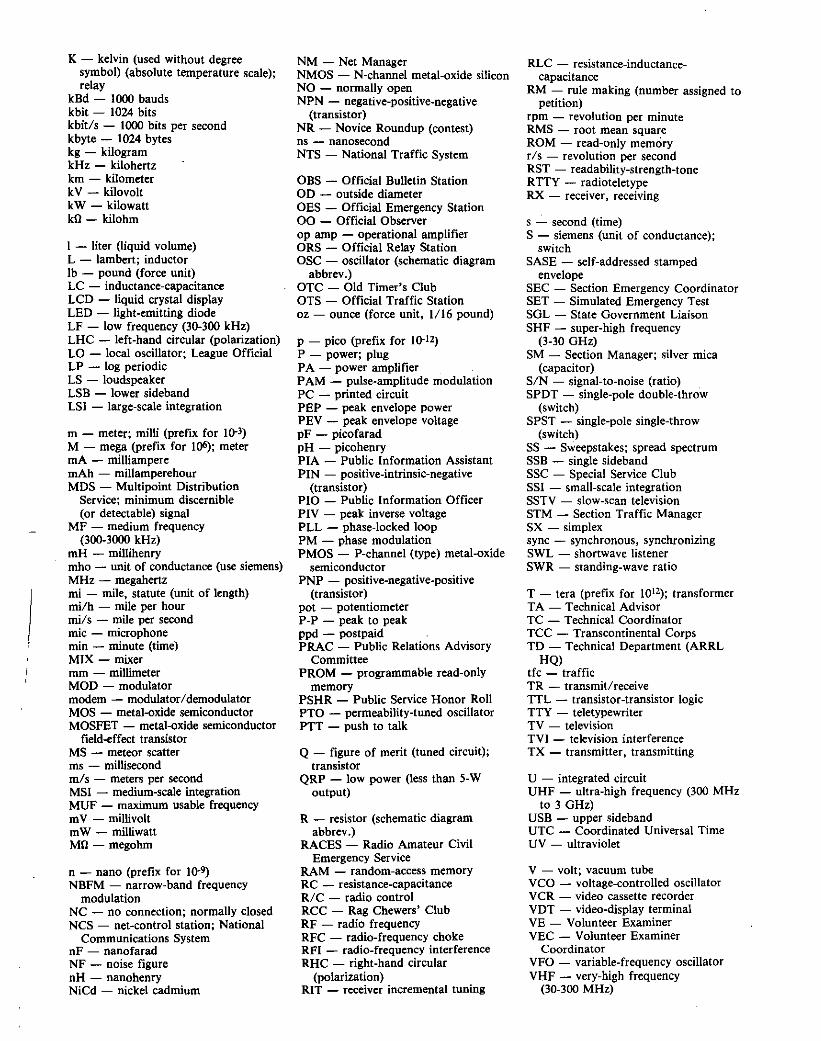
i
K - kelvin (used without degreesymbol) (absolute temperature scale);relay
kBd - 1000 baudskbit - 1024 bitskbit/s - 1000 bits per secondkbyte - 1024 byteskg - kilogramkHz - kilohertzkm - kilometerkV - kilovoltkW - kilowattkll - kilohm
I - liter (liquid volume)L - lambert; inductorlb - pound (force unit)LC - inductance-capacitanceLCD - liquid crystal displayLED - light-emitting diodeLF - low frequency (30-300 kHz)LHC - left-hand circular (polarization)LO - local oscillator; League OfficialLP - log periodicLS - loudspeakerLSB - lower sidebandLSI - large-scale integration
m - meter; milli (prefix for 10-3)M - mega (prefix for 1()6); metermA - milliamperemAh - millamperehourMDS - Multipoint Distribution
Service; minimum discernible(or detectable) signal
MF - medium frequency(300-3000 kHz)
mH - millihenrymho - unit of conductance (use siemens)MHz - megahertzmi - mile, statute (unit of length)rni/h - mile per hourmils - mile per secondmie - microphonemin - minute (time)MIX - mixermm - millimeterMOD - modulatormodem - modulator/demodulatorMOS - metal-oxide semiconductorMOSFET - metal-oxide semiconductor
field-effect transistorMS - meteor scatterIDS - millisecondmls - meters per secondMSI - medium-scale integrationMUF - maximum usable frequencymV - millivoltmW - milliwattMll- megohm
n - nano (prefix for 10-9)NBFM - narrow-band frequency
modulationNC - no connection; normally closedNes - net-control station; National
Communications SystemnF - nanofaradNF - noise figurenH - nanohenryNiCd - nickel cadmium
NM - Net ManagerNMOS - N-channel metal-oxide siliconNO - normally openNPN - negative-positive-negative
(transistor)NR - Novice Roundup (contest)ns - nanosecondNTS - National Traffic System
OBS - Official Bulletin StationOD - outside diameterOES - Official Emergency Station00 - Official Observerop amp - operational amplifierORS - Official Relay StationOSC - oscillator (schematic diagram
abbrev.)OTC - Old Timer's ClubOTS - Official Traffic Stationoz - ounce (force unit, 1/16 pound)
p - pico (prefix for 10-12)
P - power; plugPA - power amplifierPAM - pulse-amplitude modulationPC - printed circuitPEP - peak envelope powerPEV - peak envelope voltagepF - picofaradpH - picohenryPIA - Public Information AssistantPIN - positive-intrinsic-negative
(transistor)PIO - Public Information OfficerPIV - peak inverse voltagePLL - phase-locked loopPM - phase modulationPMOS - P-channel (type) metal-oxide
semiconductorPNP - positive-negative-positive
(transistor)pot - potentiometerP-P - peak to peakppd - postpaidPRAC - Public Relations Advisory
CommitteePROM - programmable read-only
memoryPSHR - Public Service Honor RollPTO - permeability-tuned oscillatorPTT - push to talk
Q - figure of merit (tuned circuit);transistor
QRP - low power (less than 5-Woutput)
R - resistor (schematic diagramabbrev.)
RACES - Radio Amateur CivilEmergency Service
RAM - random-access memoryRC - resistance-capacitanceRIC - radio controlRCC - Rag Chewers' ClubRF - radio frequencyRFC - radio-frequency chokeRFI - radio-frequency interferenceRHC - right-hand circular
(polarization)RIT - receiver incremental tuning
RLC - resistance-inductancecapacitance
RM - rule making (number assigned topetition)
rpm - revolution per minuteRMS - root mean squareROM - read-only memoryr/s - revolution per secondRST - readability-strength-toneRTTY - radioteletypeRX - receiver. receiving
s - second (time)S - siemens (unit of conductance);
switchSASE - self-addressed stamped
envelopeSEC - Section Emergency CoordinatorSET - Simulated Emergency TestSOL - State Government LiaisonSHF - super-high frequency
(3-30 GHz)SM - Section Manager; silver mica
(capacitor)SIN - signal-to-noise (ratio)SPDT - single-pole double-throw
(switch)SPST - single-pole single-throw
(switch)SS - Sweepstakes; spread spectrumSSB - single sidebandSSC - Special Service ClubSSI - small-scale integrationSSTV - slow-scan televisionSTM - Section Traffic ManagerSX - simplexsync - synchronous, synchronizingSWL - shortwave listenerSWR - standing-wave ratio
T - tera (prefix for 1012) ; transformerTA - Technical AdvisorTC - Technical CoordinatorTce - Transcontinental CorpsTD - Technical Department (ARRL
HQ)tfc - trafficTR - transmit/receiveTTL - transistor -transistor logicTTY - teletypewriterTV - televisionTVI - television interferenceTX - transmitter I transmitting
U - integrated circuitUHF - ultra-high frequency (300 MHz
to 3 GHz)USB - upper sidebandUTC - Coordinated Universal TimeUV - ultraviolet
V - volt; vacuum tubeVCO - voltage-controlled oscillatorVCR - video cassette recorderVDT - video-display terminalVE - Volunteer ExaminerVEe - Volunteer Examiner
CoordinatorVFO - variable-frequency oscillatorVHF - very-high frequency
(30-300 MHz)
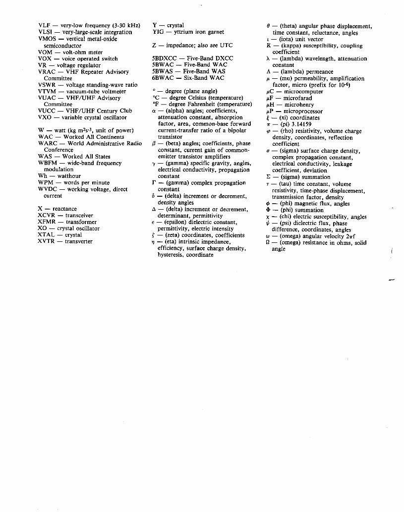
VLF - very-low frequency (3-30 kHz)VLSI - very-large-scale integrationVMOS - vertical metal-oxide
semiconductorYOM - volt-ohm meterVOX - voice operated switchVR - voltage regulatorVRAC - VHF Repeater Advisory
CommitteeVSWR - voltage standing-wave ratioVTVM - vacuum-tube voltmeterVUAC - VHF/UHF Advisory
CommitteeVUCC - VHF/UHF Century ClubVXO - variable crystal oscillator
W - watt (kg m2s·3, unit of power)WAC - Worked All ContinentsWARe - World Administrative Radio
ConferenceWAS - Worked All StatesWBFM - wide-band frequency
modulationWh - watthourWPM - words per minuteWVDC - working voltage, direct
current
x - reactanceXCVR - transceiverXFMR - transformerXO - crystal oscillatorXTAL - crystalXVTR - transverter
Y - crystalYIG - yttrium iron garnet
Z - impedance; also see UTe
5BDXCC - Five-Band DXCC5BWAC - Five-Band WAC5BWAS - Five-Band WAS6BWAC - Six-Band WAC
c _ degree (plane angle)°C - degree Celsius (temperature)OF - degree Fahrenheit (temperature)a - (alpha) angles; coefficients,
attenuation constant, absorptionfactor, area, common-base forwardcurrent-transfer ratio of a bipolartransistor
(3 - (beta) angles; coefficients, phaseconstant, current gain of commonemitter transistor amplifiers
'Y - (gamma) specific gravity, angles,electrical conductivity, propagationconstant
I' - (gamma) complex propagationconstant
o- (delta) increment or decrement,density angles
.a - (delta) increment or decrement,determinant, permittivity
€ - (epsilon) dielectric constant,permittivity, electric intensity
r - (zeta) coordinates, coefficients'Y/ - (eta) intrinsic impedance,
efficiency, surface charge density,hysteresis, coordinate
o- (theta) angular phase displacement,time constant, reluctance, angles
t - (iota) unit vectorK - (kappa) susceptibility, coupling
coefficientA - (lambda) wavelength, attenuation
constantA - (lambda) permeanceI' - (mu) permeability, amplification
factor, micro (prefix for 10-6)
p,C - microcomputerp,F - microfaradJlH - microhenryJlP - microprocessor~ - (xi) coordinates" - (pi) 3.14159cp - (rho) resistivity, volume charge
density, coordinates, reflectioncoefficient
(J - (sigma) surface charge density,complex propagation constant,electrical conductivity, leakagecoefficient, deviation
r: - (sigma) summationT - (tau) time constant, volume
resistivity, time-phase displacement,transmission factor, density
cP - (phi) magnetic flux, angles<I> - (phi) summationX - (chi) electric susceptibility, angles'" - (psi) dielectric flux, phase
difference, coordinates, anglesw - (omega) angular velocity 211"f
n - (omega) resistance in ohms, solidangle

SuppHers List======
This list covers only suppliers that arementioned in this book. The information was verified before printing. Amuch larger list of suppliers (which isupdated annually) appears in each edition of The ARRL Handbook. In addition, several of these suppliers regularlyadvertise in QST.
Advanced Receiver ResearchBox 1242Burlington, CT 06013203-582-9409
Amateur Electronic Supply5710 W Good Hope RdMilwaukee, WI 53223414-358-0333
Amidon Associates, IncPO Box 956Torrance, CA 90508310-763-5770fax 310-763-2250
Amphenol(Check with local 2-wayshops and parts suppliers.)
Antique Electronic SupplyPO Box 27468Tempe, AZ 85285-7468602-820-5411
Barker & Williamson10 Canal StBristol, PA 19007215-788-5581
Circuit Board SpecialistsPO Box 951Pueblo, CO 81002-0951719-542-4525
Digi-Key Corporation701 Brooks Ave SBox 677Thief River Falls, MN 56701-0677800-344-4539fax 218-681-3380
Eastern Bearings, Inc7096 S WillowManchester, NH 03103603-668-3300
Fair Radio Sales Co, IncPO Box 11051016 E Eureka StLima, OH 45802419-227-6573fax 419-227-1313
Int'l Radio and Computers, Inc3804 South US 1Fort Pierce, FL 34982407-489-5609
GLB Electronics151 Commerce PkwyBuffalo, NY 14224716-675-6740(no longer sells TNCs)
Industrial Polychemical Service17109 S Main StGardena, CA 90247213-321-6515
J. W. Harris Co, Inc (solder)10930 Deerfield RdCincinnati, OH 45242513-891-2000fax 513-891-2461
J. W. Miller Co(distributed through Digi-Key)
Johnson Mfg CoPrinceton, IA 52768319-289-5123
Kester Solder515 E Touhy AveDes Plaines, IL 60018-2675708-297-1600fax 708-390-9338
MFJ EnterprisesPO Box 494Mississippi State, MS 39762601-323-5869
Motormite Manufacturing3400 E Walnut StColmar, PA 18915215-997-1800
Mouser Electronics2401 Hwy 287 NMansfield, TX 76063800-346-6873
Ocean State ElectronicsPO Box 1458Westerly, RI 02891800-866-6626fax 401-596-3590
Palomar EngineersPO Box 462222Escondido, CA 92046619-747-3343
RADIOKITPO Box 973Pelham, NH 03076603-635-2235fax 603-635-2943Telex 887697
Small Parts IncPO Box 4650Miami Lakes, FL 33014-0650305-557-0822

About The American Radio Relay LeagueThe seed for Amateur Radio was planted in the 1890s, when Guglielmo Marconi
began his experiments in wireless telegraphy. Soon he was joined by dozens, thenhundreds, of others who were enthusiastic about sending and receiving messagesthrough the air-some with a commercial interest, but others solely out of a love forthis new communications medium. The United States government began licensingAmateur Radio operators in 1912.
By 1914, there were thousands of Amateur Radio operators-hams-in the UnitedStates. Hiram Percy Maxim, a leading Hartford, Connecticut, inventor and industrialistsaw the need for an organization to band together this fledgling group of radioexperimenters. In May 1914 he founded the American Radio Relay League (ARRL) tomeet that need.
Today ARRL, with about 160,000 members, is the largest organization of radioamateurs in the United States. The League is a not-for-profit organization that:
• promotes interest in Amateur Radio communications and experimentation• represents US radio amateurs in legislative matters, and• maintains fraternalism and a high standard of conduct among Amateur Radio
operators.At League Headquarters in the Hartford suburb of Newington, the staff helps serve
the needs of members. ARRL is also the International Secretariat for the InternationalAmateur Radio Union, which is made up of similar societies in more than 100 countriesaround the world.
ARRL publishes the monthly journal QST, as well as newsletters and manypublications covering all aspects of Amateur Radio. Its Headquarters station, Wl AW,transmits bulletins of interest to radio amateurs and Morse Code practice sessions. TheLeague also coordinates an extensive field organization, which includes technicalinformation for radio amateurs and pubnc-service activities. ARRL also represents USamateurs with the Federal Communications Commission and other government agenciesin the US and abroad.
Membership in ARRL means much more than receiving QSTeach month. In additionto the services already described, ARRL offers membership services on a personal level,such as the ARRL Volunteer Examiner Coordinator Program and a QSL bureau.
Full ARRL membership (available only to licensed radio amateurs) gives you a voicein how the affairs of the organization are governed. League policy is set by a Boardof Directors (one from each of 15 Divisions). Each year, half of the ARRL Board ofDirectors stands for election by the full members they represent. The day-to-dayoperation of ARRL HQ is managed by an Executive Vice President and a Chief FinancialOfficer.
No matter what aspect of Amateur Radio attracts you, ARRL membership is relevantand important. There would be no Amateur Radio as we know it today were it not f6rthe ARRL. We would be happy to welcome you as a memberl (An Amateur Radio licenseis not required for Associate Membership.) For more information about ARRL andanswers to any questions you may have about Amateur Radio, write or call:
ARRL Educational Activities Dept225 Main StreetNewington, CT 06111(203) 666-1541
,

.. .... 5-20.5-18, 5-21
. . 5-12
. ..... 1-2.. .. 5-23
. ... 5-6, 5-7
...... 7-10.... 9-5
....... 4-1.... 6-7
.. .... 5-3,5-4........... 5-2
......... 5-3, 10-8........... ...5-4
.... 5-7.. 9-3
.... 6-2... 6-3
D0-104 microphone: , .1-14D-C receivers:. . . . . . . .5-4Deep-cycle batteries: ".. . .. 2-1Demagnatize tools:. . . . ,5-12Deodorant-stick containers:. . . . .5-21Detectors: , 5-4Dexterity, with gloves: , 7-14Dial slippage (HW-101):.. . 1-5Digimax 0-500:. , , . . . ,6-1Digital rnodes. . 1-1Diodes:
At low voltages:...Clamp indicator:.Hum: ..... " ... .Schottky: .TR switch:. . . .
Dip-switch key:. . ..Display, frequency:. , , ...DMM range:.
Commodore 64 (C-64): 9-11Commodore MPS-1000 computer: 9-3Compatibility, equipment: .... , .. , 9-10Computers:
C-64: . . 9-11Digital modes: , , 1-1Dip-switch key: , .. , 9-3EIA-232-D keying interface:. . .9-16Interference: 10-6
Concrete cutting:."."." 7-15Conductive:
Glue: 5-20Grease: . . 7-6Plastic and batteries: 2-3Tape antenna (144 MHz): 7-28Tape antenna (440 MHz): 3-5
Conduit, wire pulling:. .. . .. . . .. 7-18Confidential Frequency List; . . . . . . .. 1·36Connections, quick, for safety: 9-7Connectors:
Auto de:. . . . . . . . . . . . . . . . . . .3-1Cable breakage at:. . . . . . . . . . .7-8Cable stripping: . , . , .. , . . . . . . .7-6Faults: 3-5Hardline: , . , . . . . . . . . . 7-6Installation, BNC and N:. . . . .7-6Installation, PL-259:. .. .. 7-1ftPin markings: 5-11Pros and cons:. . . . . . . . . . 7-4Protection: , , , 7-6Replacement, multipin:. . .5-23Solderless, coax:.. . . . 7-1Vertical antennas:. . . . . . 7-29
Construction:Boxes: , . . . . . . . . . . 5-11~~I, winding:. . , , 5-11
D holes: 5-10PC boards: 5-12, 5-13PC-board boxes:.. " 5-10Pin identfication: ,5-11Tips: ".. . 5-11
Contests:Pencil control:. . , , 8·3Practice: . . . . . , 9-11
Converter, 10115 meters to 80 meters:. 1-32Copper-foil, connector installatlcn.. , 7-3Cordless-phone RFI:...... . 10-3Cores, ferrite: , 5-6,5-19,10-2Correction-fluid labels: 5-15Courtesy-tone generator: 9~2
Cover for thrust bearings: , , 7-17CPU reset: 1-12, 1-13, 9-8CO Ham Radio magazine: , . . 1-32, 7-20Crank-Up tower motor:. . 7-17Crystal sockets:".,...... . 5-20Current limiter:.......... . , , , .6-5Cushcraft A3 sealing:..... . 7-8CW: See aiso "Keying".. . ... . . .1-1
Keying: , . . . . . . . . . 1-13Monitor, Heath HR-1680:.. .1·4QSK AGC system: .. " 5-8Resonant speaker:. . . 9-16ffTS·44OS:. . . . . . . . . . . .1-21, 1-22
CCable breakage at connectors: 7-8Cable-jacket lubricant: 7-3Capacitance, stray in measurements:, . .6-3Capacitors:
Charge danger note:. . , .. 9-11Cure diode hum.. . . 5-3Repair:.. .. .. .. 5-18Salvage from TV:. . ,5-18
Carrier, antenna:. . . . . 4-1, 4-2CATVI: 10-2Ceramag 11:. . . . . . . . . , .5-6Chokes, as autotransformers: 5-6Cigar-lighter polarity tester: 3-2Climbing, tower shields:.. . . . .7-15Clipperton L: 9-8Club-night fun:....... .. .9-11Coax:~~~:... ...........~
Jacket lubricant... . 7-3Parallel feed lines:. . 7-7Stripping: . . . . , 7-6Strain relief: ,7-8
Coax-Seal: . . . . . . . . . . . . . . . . . 7-31Coax-Seal warning:.... . . .7-8Coaxial connector hood:.. . 7-5Coil:
Dope:. . .Forms: .Winding: .
Collins:R-390: ........R-392 connectors: .VFOs: .
BBaby-bottle balun: .Badge lights: .Bag for QAP station: .Balanced dummy load: .Behrns:
Baby bottle: .7-10For TVI:.. .. 10-1Shieid choke: 7-9
Barbeque spit for coil winding:.. . . . 5-12Batteries:
AAA charging:. .. . .. . .. . . 2-2And conductive plastic: 2-3Backup replacement:......... . . 1-13Charge labels:.. .. 2-2, 2-3Charger: 2-2, 2-3, 2-5Charging tlrner: . .2-1Deep cycle:.. .. .. 2-1Free NiCds:. . .2-1Fusible links:. .. . 2-3IC-2AT: . . . . 1-12Icom BP-7 and BP-70:. .1-12Icom BP2, BP3, BP4, BP5:. . . . . .2-2Lead-acid: . . . . . . . 2-1Polaplus: . . . . . . . . . . . . . . . . .. 2-1Protective case:. . 2-3Source: . . . . . . . 2-1VCR: . . . . 2--1
Beacons, VHF:. . 8-2Beams:
Calibration: . . . . . .. . . 7-19Matching:. . . . . . . 7-23Element mount:. . . . . , . . . .7-23Headings:. . . . . . . . . . . . . .8-2, 8-3Quad, life:............. . 7-21Sigma: .. . 7-20
Beep-Over: . . . . 9-2Bolts, spade:. . 5-20Boxes, from PC board:. . . 5-10Brake control for HDR 300:. . 7-18Brass sheet source:. . ... , , .5-21Breath-actuated key:. . . .9-12Broadband antennas: . . . . . , . . . . 7-26Broadband circuitry:. . . 9-9"Bug," Slow keying with a:...... . .9-12Built-in speaker grilles: 3-3Burglar-alarm tape antenna: 7-28Burying coax:.. . . . . 7-8Butternut HF2V vertical antenna: 7-30
AAAA battery charging: 2-2AC power:
Safety: 9-7Switches:. . . . . . 9·1, 9·7
Accukeyer for positive keying: 9-15Adhesive pads (PC boards):. .. . . .5-13Advanced Receiver Research:
MM144VDG protection:.. . 9-8AEA PK-232:. . 1-1AEASOFT cartridge: . . . . .. 9-11AGe control for HW-9: . . 1-5AGC system:. . . 5-8Air-cleaner interference: . . . . . . . .10-5Airline shipping limits:. . . . 4-2Alarm, doorbell:............ . .. 9-3Alternator connectors for de: 3-1Aluminum-gutter screen shielding: 5-21AM broadcast receiver:. . 1-35Ameritron: AL·12QO:.......... . 1-1Amplifiers:
And Kenwood transceivers:. . . .. 1-23Dentron Clipperton L:. . . . 9-8Matching: 9-8Power: , 1-1Source follower: 5-5TR switching:. . . . . . . . . . . .1-7 to 1-9Tube and socket repair: 5-23
AMTOR see "Rny"Antennas:
Adjustment:. . ..... 7-11, 7-14Beam headings: ..... 4-4,7-19,8-2,8-3Beam matching:... .7-23Broadband: 7-26Carrier: .. , . . . . . . . . 4-1, 4-2Conductive tape: . .7-28Element mount.. . . 7-23Indoor dipole: 1-26Insulators: . . . . . 7-14Inverted V:. . 7-13, 7-26J: .. .. .. . .. 4-2, 7-31Mag mount: , . . . . . . . 3-6Plumbing fixtures for:. . 7-7Quad, life:............ . .. 7-21Repair template:. . ,7-13Ring-magnet sources:. . . 5·19RTV: . . .. . . .. . .. . .. . .. 7-9Seating: 7-8Short dipole:........... . .. 7-27Sigma beam:. . 7-20Snug tubing:. .. 7-14Standoff mount:... . 7-16Switching: . . . . 7-24Tower shields:. . , 7-15Vertical: . . . .7-29 to 7-31Whip tips:. .. 5-11Wooden mast:. . , 7-111.8-MHz: . . . . . . . . 7-242-meter J-pole or beam, portable: 4-22-meter mobile:. , , . . . . . . . 3-56-meter loop:. . . . . . . . . . 7-2730/40-meter loop: .7-2640/15 meters:. . , 7-25ten-meter: . , ,7-24440·MHz tape: .. . .. 3-5
Antistatic treatment: , . , . . . 9-5Apex template (antenna): , .. ,7-13Aquadag: . . 5-20Argosy 525 frequency jumps:. . , 1-27ASCII transmissions, see "RTTY"Astatic [)..104 microphone: 1-14Attenuator, 20-dB: 1-16Audio generator:. .6-4Audio VCO:.. .. .. .. . .. 8-4Audio-tape keyer:..... . 9·12Auto speaker mounts:. . . , . .3-3Auto-microprocessor interference: 10-5Award endorsement tracking:. . .8-3
INDEX
I
165
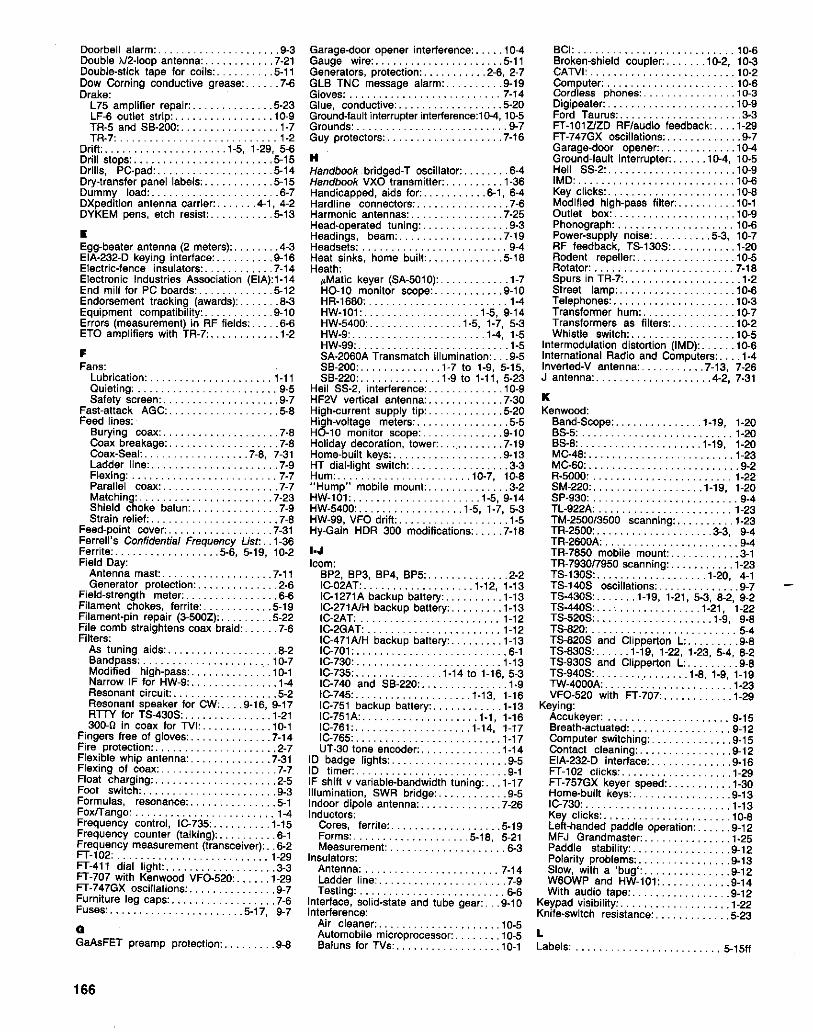
BCI: 10-6Broken-shield coupler: 10-2, 10-3CATVI: 10-2Computer: . . . . . . . . . . . . . . .. . 10-8Cordless phones: 10M3Oigipeater: 10-9Ford Taurus: 3·3FT-101ZJZD RFtaudio feedback: 1-29FT-747GX oscillations: 9·7Garaqs-door opener: 10-4Ground-fault interrupter: 10-4, 10·5Heil SS-2: 10-9IMD: 10-6Key cltcks: . . la-8Modified high-pass filter: 10-1Outlet box: 10-9Phonograph: 10-6Power-supply noise: 5M3, 10M7RF feedback, TS-130S: 1-20Rodent repeller: 10-5Rotator: 7-18Spurs in TRM7: IM2Street lamp: 10-6Telephones: 10·3Transformer hum: 10-7Transformers as filters: 1()..2Whistle switch: 10-5
Intermodulation distortion (IMO): 10-6International Radio and Computers: 1-4Inverted-V antenna: 7~13, 7-26J antenna: 4--2, 7·31
KKenwood:
Band-Scope:. . . 1-19, 1-20BS-5: . . . . 1-20BS-8:. . . . . . . . . . . 1-19, 1-20MC-48: . . . . . . . . . . . 1-23MC-50: 9-2R-5000: 1-22SM-220:.. . .. .. 1-19, 1-20SP-930: 9-4TL-922A: 1-23TM-2500t3500 scanning: 1-23TR-2500: 3-3, 9-4TR-2600A: 9-4TR-7850 mobile mount: 3-1TR-793017950 scanning: 1-23TS-130S: 1-20, 4-1TS-140S oscillations: 9M]TS-430S: 1-19, 1-21,5-3,8-2,9-2TS-440S: 1-21, 1-22TS-520S: 1-9, 9-8TS-820: 5-4TS-820S and Clipperton L: 9-8TS-830S: 1-19, 1-22, 1-23, 5-4, 8-2TS-930S and Clipperton L: 9-8TS-940S: 1-8, 1-9, 1-19TW-4000A: : .. . .. . 1-23YFO-520 with FT-707:.. . 1-29
Keying:Accukeyer: . . . . . . . . . .. . 9-15Breath-actuated: . .. . .. . . 9-12Computer switching: 9-15Contact cleaning: 9-12EIA-232-D interlace: 9-16FT-102 clicks: 1-29FT-757GX keyer speed: 1-30Home-built keys: 9-131C-730: 1-13Key clicks: 10M8Left-handed paddle operation: 9-12MFJ Grandmaster: 1-25Paddle stability: 9-12Polarity problems: 9-13Slow, with a 'bug': 9-12~~~WP and HW-l01: 9-14
audio tape 9-12Keypad visibility: IM22Knife-switch resistance:....... . .. 5-23
Doorbell alarm: 9M3
Double }J2-loop antenna: 7M21Douole-stlck tape for coils:. .5 M11Dow Corning conductive grease: 7-6Drake:
L75 amplifier repair:. . 5M23LF-6 outlet strip:. . . . . . . . . . .. 10-9TR-5 and SB-200:....... . 1-7TR-7: 1-2
Drift: 1-5, 1-29, 5-6Drill stops: 5-15Drills, PC-pad:.......... . .. 5-14Dry-transfer panel labels: 5-15Dummy load: 6M7DXpedition antenna carrier: 4-1, 4-2DYKEM pens, etch resist:..... .5-13
EEgg-beater antenna (2 meters): . . .4M3
EIAM232-D keying interface:. . . .9M16Electric-fence insulators:...... .7-14Electronic Industries Association (EIA):1-14End mill for PC boards: . . . .5-12Endorsement tracking (awards):.. . . .8-3Equipment compatibility:. .9-10Errors (measurement) in RF fields: . . .6 M6ETO amplifiers with TR-7:. . . .1-2
FFans:
Lubrication: 1-11Quieting: . . . . . . . . . . . . . . . . . . . 9-5Safety screen:. . . 9-7
Fast-attack AGC:. . 5-8Feed lines:
Burying coax:.. . 7-8Coax breakage: . . . . . . . . . . .7M8Coax-Seal: 7-8, 7-31Ladder line:. . . . . . . . . . . . . . . . 7M9Flexing: 7M7Parallel coax: 7-7Matching:. . . . . . . . . . . . . . . . . . . . 7-23Shield choke balun: 7-9Strain relief: 7-8
Feed-point cover: 7-31Ferrell's Confidential Frequency Ust: . . 1-36Ferrite: 5-6, 5M19, 10M2Fiald Day:
Antenna mast: 7MllGenerator protection:.... . 2M6
Field-strength meter:....... . 6M6Filament chokes, ferrite: 5-19Filament-pin repair (3-500Z):. . . . . . .5-22File comb straightens coax braid: 7-6Filters:
As tuning aids.. . . . . . . . . .8-2Bandpass: . . . 10M7Modified high-pass: 10M1Narrow IF for HW-9: 1-4Resonant circuit: 5-2Resonant speaker for CW: 9-16, 9M17RTTY for TS-430S: 1-21300MO in coax for TVI: 10-1
Fingers free of gloves: 7-14Fire protection: 2-7Flexible whip antenna: 7-31Flexing of coax: 7M7Float charging: 2-5Foot switch: 9-3Forrnufas, resonance:...... . 5-1Foxfrango: 1-4Frequency control, 1C-735: 1M15Frequency counter (talking): 6-1Frequency measurement (transceiver): . .6M2
FT-l02: 1-29FT-411 dial light: 3-3FT-707 with Kenwood YFC-520: 1-29FT-747GX oscillations: 9M7Furniture leg caps:. . . . 7M6Fuses: 5.17, 9-7
oGaAsFET preamp protection:. . . ... .9-8
166
Garage-door opener interference: 10-4Gauge wire: 5-11Generators, protection: 2-6, 2-7GLB TNC message alarm:. . .9 M19Gloves: . . .. . . .. . .. . .. . .. . 7M14Glue, conductive: 5-20Ground-fault interrupterinterference:1Q-4, 10-5Grounds: . . .9M7Guy protectors:. . . . . . . . . . . . . . . .7 M16
HHandbook bridged-T oscillator: 6-4Handbook VXO transmitter: 1-36Handicapped, aids for:. . 6M1, 6-4Hardline connectors:..... . 7-6Harmonic antennas:. . . . 7-25Head-operated tuning: 9M3Headings, beam: 7-19Headsets: . . . . . . . . . . . . . . 9-4Heat sinks, home built:. . . . 5-18Heath:
_Matic keyer (SA-5010): 1-7HC-l0 monitor scope: 9-10HR-1680: 1-4HW-l01:.... .. 1-5,9-14HW-5400: 1-5, 1-7, 5-3HW-9: 1-4, 1-5HW-99: 1-5SA-2060A Transmatch illumination: 9M5SB-200: 1-7 to 1-9, 5-15,SB-220:..... . 1-9 to 1-11, 5-23
Heil SS-2, interference: 1OM9HF2V vertical antenna: 7-30High-current supply tip:. . 5-20High-VOltage meters:..... . 5M5HOM10 monitor scope: 9-10Holiday decoration, tower: . . '.' 7-19Home-built keys: 9-13HT dial-light switch: 3-3Hum: 10-7, 10-8"Hump" mobile mount: 3-2HW-l01:.. . . 1-5, 9-14HW-5400: 1-5, 1-7, 5-3HW-99, YFO drift: 1-5Hy-Gain HOR 300 modifications: 7M18
I.JIcom:
BP2, BP3, BP4, BPS: 2-21C-02AT: ... '" .. .. . .. .. 1-12, 1-131C-1271A backup battery:. . .. 1-131C-271A1H backup battery: 1-131C-2AT: . . .. . . 1-121C-2GAT: 1-12IC-471A1H backup battery: 1-13IC-701: 6-1IC-730: 1-13IC-735:. . . 1-14 to 1-16, 5-3IC-740 and SB-220:..... . ... 1-91C-745: 1-13, 1-16IC-751 backup battery: 1-13IC-751A: 1-1, 1-16IC-761: 1-14, 1-17IC-765:.. . . 1-17UT·30 tone encoder: 1-14
ID badge lights: 9-510 timer: 9-1IF shift v variable-bandwidth tuning: 1-17Illumination, SWR bridge: 9-5Indoor dipole antenna: 7-26Inductors:
Cores, ferrite:. . 5.19Forms:. . . . . . . . . . . 5M18, 5-21Measurement: &-3
Insulators:Antenna: 7M14Ladder line: 7-9Testing: . . . . . . . . . . . . . . . . . . . . .. .. 6M6
Interface, solid-state and tube gear: . .. 9-10Interference:
Air cleaner: 10-5Automobile microprocessor: 10-5Baluns for TVs:. . .. . . 10-1
LLabels: ................... 5-15ff

Ladder line construction: 7-9Lamps: .. " . .. . .. . .. . .. . . , .. 5-12LCD displays and static.. . . . .9~5Lead-acto batteries:... . .2-1LED panel mount:. .5-21Lexan plastic: . .5-20LF-6 outlet strip:. . . . . .10-9Lightning safety:. .. . .. . .. . .. . . 9-7Lloyd's stainless-steel flux:. . 5-16Load sensing: 5-20Loop, double ),/2:.. . .. . .. . .. . . . .. 7-21Loss (RF) test:.. .. .. .. .. . .. .. 6-6Lumocolor pens, etch resist: 5-13
NNail polish, etch resist:...... . .5-13National Weather Service as beacons:.. 8-2Neophyte receiver: 1-35, 1-36New meter faces:.... . 5-14NiCds, free:. . , " 2-1NOAA stations as beacons: 8-2Noise:
Diode hum cure:. . . . . . . . . . . .5-3Ford Taurus:.. . . . . . . . . .3-3From connectors:. . 7-1In detectors: , 5-4Suppression for HDR 300:.. . . 7-18
Noise~bridge techniques: 6-6, 8-1Notch filter, for tuning: . . . . .. 8~2Nuts, replacement:. . .5-20
Knife switch:....... . 5~23Coil slugs: 5-11Mobile antenna:.... . 3-5Nut replacement: ,5-20Resistors: .. , 5-1Transistors: 5-18Tube caps: 5-17, 5-23Vacuum tubes: 5-212C39 heater connections: 5-23
Resistance measurement: , .. 6-3Resistor substitution:., , , .. 5-1Resonance formula: ' 5-1RF probes: 5-3, 5-4RF properties test.. . . .6-6RF-sensing mobile fan:. . . . 3-2Rlnq-maqnet sources: 5-19RIT, improved, HW-5400: 1·5Robot 800C as typewriter: , 9-11Rodent-repeller interference: 10·5Rohn 25 tower:.. . . .. . .. . .. . .. .7-16Roller inductor switch: 5-1Rotators:.... ...... .. .. 7-15, 7-18RS-232-C, see "EIA-232-D"RTTY: . . . .. . .. . .. . . 1-1
ALC: '" 9-4Computer swltchlnq.. . . .9-15Filter for TS-430S: 1·21Tuning aid: . . 9-10
RTV: . . .. . .. . . .. . .. . .. . 7-9
SSA-SOlO, Heeth _Matic keyer: 1-7Safety:
AC wiring practices: 9·7Concrete cutting:........... ..7-15Generator, fire:........... . 2-7High voltage:. . . . . . . . . . . . . . . . . .5-5Lightning: 9-7Tilt up towers:. . . . . . . . . . . 7-17Tower shields: , 7-15
Sanford Sharpie pens, etch resist: 5-13SB-200 TR switching: 1-7, 1-8, 1-9SB-220: 1-9 to 1-11Scanning for TM-2500/3500:. . .1-23Scenning for TR-793017950: 1-23Scratches, mag mount:. . . 3-6Sequential ac-power switch: 9-1Series-section transformer: 7-23Shield choke balun:. . . . 7-9Side mount for towers: 7·16Sigma beam antenna: 7-20Sil-Strong solder:. . 5-18Single sideband:. . 1-2Slide element mount:. . , .7-23Sockets, 3-500Z, repalr: . . 5-23Sockets, crystal: 5-20Soldering:
Connectors:. . , 7-5To stainless steel: 5-16ff
Solid-stateltube interfacing: , . .9-10Source-follower amplifier:.. . 5-5Spade bolts:. . 5-20Speakers:
Auto mounts:. . .. , 3-3Outboard: . . . . . . 9-4Resonant, for CW: 9-16, 9-17SP-930: . .. ... 9-4Switching and RFI:. . .10-9
Speedy Tune:.. .. .. 1-7Sponge, soldering: 5·11Spurs, in TR-7: , 1-2SS-2 sound-system interference: 10-9Stackpole Ceramag 11:. . . . . . 5-6Staedler Lumocolor pens etch resist: .. 5-13Stainless steel, soldering: 5-16ffStandby switch, SB-220/221: 1-9Standoff antenna mount: 7-16Static, and Heath SA-5010:. . 1-7Stay bright solder:.... .. .. .. .. .. .5-16Storing QST:........ .. 9-11Strain relief for coax: 7·8Stray capacitance:...... . .6~3Street-lamp interference: 10-6
· .. 1-2· .1·22
. .... 7-8.7-29.1-26
· .9-11
...... 5-18· . 5-17
RR-390, Collins receiver:. .R-5ODO keypad visibility: ....R3 (Cushcraft) antenna: .Radial materials: , .Radio Shack HTX-100: ..Radioless fun: . . . . .Receivers:
As audio generator:. . 6-4As neutralization indicator:. . . .6-3D-C, AM detection:. . . . . . . ... 5-4To measure frequency:. . .6-2Tricks for noisy bands:. . . . . .... ,8-210· and 18-MHz:............ . .5-10
Reed switch for HT dial light:. . 3-3Relay contact pitting:. , . . . . 1-10Repair:
Capacitors: . .Fuses: ...
pPack for CRP station:.. . .. 4-1Packet (HF, see "RTTY")
Connect alarm: 9-18, 9-19Digipeater interference:..... . 1Q..9Switch box:,... . 9~18
Paddle stability:. . 9-12Panoramic display:.. . .. . . 1·19Paper-clip meter shunts:. . .5-20Parallel connected coax:. . . .7-7Passband tuning:...... . .1-17PC-board boxes:. . . . 5-10pe-pad drills:. .. 5-14Pencil control for contests: 8-3Petroleum jelly and coax:. . . . . . . . 7-3Phonograph interference: 10-6Photocopier film (PC board): 5-14Pigtails adjust antenna:.. . , .7-14Pin identification:...... .5-11PL-259 lnstatlatlon: . . .. . .7-1ffPlate-cap connectors:. . . , 5~3prate-current meters:. . .5-5Plug-in breadboards and IC sockets:.. 5-11Plumbing fixtures for antennas:. . . .7-7Polaplus batteries:......... . . .2-1Polarity tester (automotive): 3-2Portable antennas: , , 4-2 to 4-4Power fold back circuits: , 9-9Power supplies:. . . . 2-3, 2-5
High current: 5-20Noise: . . . . . . . . . 10-724-28 V: 5-1
Preamplifier protection: , 9-8Predrilled PC boards.. . .. . .5-14Product-detector performance:.... . .5-4Pros and cons, solderless connectors:. .7-4Protection, SWR:. . 9-9Pruning, antenna:. , . . . . . .7-11PVC guy protectors:. . 7-16
Q
Q-section transformer:.,. . .7·23CRP:
Carrier: , . . . . 4-1Resonant filter:.. . . 5-2TR switch:.... . 5-7
CSK AGC system:. .. 5-8QSK amplifiers with TR-7:. . . 1-2QSL holders:.. , . . . . . . . . . . 9-11OST bags for heat shnnk: . 5~21
QST storage: . . . . . 9-11Quad antenna life:. . . 7-21Quiet muftin tans., . . 9-5
One MOSFET Converter: 1-32One-shot timer: 2-1Open-wire line, see "Ladder line"Oscillators (see VFO):
Audio: 6-4Oscilloscope dual-trace converter: 6-6Outlet box EMI:....... . .. 10-9Output power of VFOs:. . 5-7Overvoltage indicator:.. . 5-2Overvoltage protection:. . 2-6
. .. 6-3
.... 3-6
... 7-11....... 7-23
.... 1-23... 9-2, 9-4
..... 5-8.. 6-3, 6-6
.1-25
.1-26. 3·1
....... 5-5......... .. .. 9-5
... 5-14
.... 5-5... 5-20
oOhmmeter range: ..
MMag-mount antennas:.Mast, antenna: , .Matching, beam: .Me-48 microphone: .Me-SO/50:... .. .MC1350P AGC circuit: .Measurements: .Meters:
High voltage: . .Illumination:. . . . .New faces: ..Plate current:.Shunts: .
MFJ:484 keyer: ..9xx tuners..949D mobile: ...
Microphones:MC-48: . .1-23Me-60/50: . . . . . . . . . . .. 9-2, 9-4Gain adjustments: 8·1Icom with D-104: 1-14
Microphonics: .. , . . . . . . . . 5-3Microprocessor, reset: 1-12, 1-13,9-8Microwave oven, for testing:. . . . .6-6Milk-crate mobile:. . . , . , . .. . . .3-1Mini-Miser's Receiver:.. . .1-33MM144VDG, protection:. . ..... 9-8Mobile:
Antenna repair:. . . . . . 3-5Dial-light switch:. . , 3-3Digipeater: , , 10-9Hump mount:.......... . . .3-2Mag-mount antennas: 3-6HTX-100 SWR:......... .. 1-26RF sensing fan:.......... . ,3-2Ring-magnet sources:. . , . . 5-19Station in crate:... . 3-1Tape antenna: , 3-5Whip stabilizer:.. . 3-4
Modems, switching:........... . . .9-15Modified work gloves:. . 7-14Molykote 41:.. .... .. 7-6Muffin fans:
Mobile: . .. . .. . . 3-2Quieting: . . . 9-5Safety:. . . . . . 9-7
Multiband antennas:7-24 to 7-26, 7-29, 7-30Multipin connectors:. . .. . 5-23
167

Switches:Foot: 9-3Roller inductor:. . 5-1
SWL, utility receiver.. . 1-35SWR:
And connectors:............ . 7·1And RF feedback: 5-3Baby-bottle balun: 7-108eam matching: 7-23Bridge illumination: 9-5Protection: , .. , .. , , .. 9-8, 9~9
Shield choke bahm: . . 7-9
TT-195 surplus VFO: 5-6"Talking" capacitors: 5-3Talking frequency display: 6-1Techniques:
Capacitor drive belts:. . 5-21Coil dope: 5-20Coil forms: 5-18, 5-21Coil winding:...... . .5-12Conductive glue:. . . . 5-20Crystal sockets:... . 5-20Demagnetize tools:. . 5-12Ferrite sources:... . . 5~19
Force fit:...... .. 5-17Fuse removal: 5-17Heat shrink: 5-21Heat sinks:......... . 5-18Labels: 5-1511LED panel mount: ,5-21Load sensing:......... .. 5-20Loose coil slugs: 5~11New meter faces: 5-14Nut replacement: 5-20PC boards: 5-1211Plastic polish:........ .. .. 5-15Plate-cap connectors: , .. , .. 5-23Predrilled PC boards: 5-14Salvage TV capacitors: 5-18Shield material: 5-21Soldering stainless eteei... 5-16TUbe-cap repair:.......... .. .. 5-17Vacuum-tube repair: , , . , .5-21Whip tips:................ .. .. 5-11Wire: 5-111/4'" knobs on 3116" shafts: 5-142C39 heater connections: 5-23
Template for antenna repair: , . , , .7-13Ten-Tee:
Argosy 525 frequency jumps: 1~27
Omni VFO leakage: " 1-26243 VFO leakage:.. .. .. .. .. .. 1-26425 amplifier with TR-7: 1-2
Tenna Phase III power supply: 5-3Thermal-drift: , 1-5, 5-6Thrust-bearing cover: 7~17Tilt-up tower safety: , , 7-17Timer, battery charging: 2~1
TL-922A: . . . . . . . 1-23TM-2500/3500: . . . . . . . . . . . 1-23TNC, see "Packet"Tone source, tuning: ,8-1Tones, subaudible: , 1-14Tools:
Demagnetizing: . . . . . ... , .... 5-12Drill stops:.. .. .. .. .. .. .. .. 5-15Etch-resist pens: , .. 5-13Labels: 5-11PC boards: 5-1211PC-pad drills:..... . 5-14Solder dispenser: , 5-11
168
Solder sponge: 5-11Spring-open pliers: 5-11Wire stripping: 5-11Work lamps: 5-12
Toroidal cores:.......... . .. , , 5-6Towers:
Beam calibration: 7-19Crank-up motor: , .. "... . .7-17Guy protectors:. . . . . . . . . . . .7-16HDR 300 modifications:. . . . .7-18Holiday decoration: 7-19Shields: . . . . . . . . . . . . . . . .7-15Standoff mount: 7-16Thrust-bearing cover: 7-17Till up: 7-17U-100 modification:.. . 7-18Universal joints:.... .. 7-15
TR switches: 5-7, 5-8TR-25OO: .. .. .. .. 3-3, 9-4TR-2800A, headset:.......... .. 9-4TR-7, Drake transceiver:. . . . . . . 1-2TR-7930/7950 scanning:. .1-23Transceiver frequency display:. . 6-2Transformer hum:. . . . . . . . . 10-7Transistor substitution: . . . . . 5-18Trap antenna (1.8 MHz): 7-24TS-13OS: 1-20, 4-1TS-140S: 9-7TS-43OS: 1-19, 1-21, 5-3, 8-2, 9-2TS-440S: 1-21, 1-22TS-520S: 1-9, 9-8TS-820S: 9-8TS-830S: 1-19, 1-22, 1-23, 5-4, 8-2TS-930S: .. .. .. .. . .. .. 9-8Tubing, snug fit: 7-14Tubing reducer as coax hood: 7-5Tullak plastic: 5-20Tune-up aids;.............. . .8-1Tune-up labels:........... .5-15Tuning capacitors, from TV: , 5~1S
Tuning, head operated: 9-3TV yokes as ferrite source:. .5-19, 10-2TVI, see "Interference"TW-4000A: . . . . . . . . . . . . . . 1-23
UU-l00 rotator:............ .. .. 7-18UG-175/176 adapter: 7-1Umbrella antenna: 7-31United Parcel Service limits: 4-1Universal joints, rotator: , 7-15Utility station receiver (SWL):. . . . . . 1-35
YVacuum cleaner pulls wires: 7-18Vacuum-tube repair: 5-21Variable-bandwidth tuning v IF shift: .. 1-17VCO, audio: 6-4VCR bauerles: 2-1VCR belts drive capacitors: 5-21Vertical feed-point cover:. . .7-31VFO:
Drift: . . . . . . . . .. . 1-5, 1-29, 5-6JFET:. . 5-7Leakage (Ten-Tee 243): 1-26Output power: 5-7Transistor conversions: S-6
VHF and ground-fault interrupters: 10-4VHF beacons: , , . . . 8-2Vibroplex, slow keying speeds: , . .9-12VOX:............ .. .. 1-1, 1-22VXO transmitter: , 1-36
WWater drives ground rooe.. . 9-7Weather protection:....... . 7-31Whip-antenna stabilizer: 3-4"Whippy whip" antenna: 7~31
Whistle-switch interference: , , .10-5"Willie" ball Insulators: 7-14Wire:
Ground: 9-7Gauge: 5-11In conduit: 7-18Storage, Straightening, Stripping: 5-11
WirinQ. practices:. . . . 9-7Work lamps:................ .. .. 5-12WWV receiver: 1-35
y·zYaesu:
FP-757HD: . .. 5-3FT-l01 ZlZD: , 1-29FT-l02: . . .. . . .. . .. 1-29FT-23R low power adjust: 1-29FT-411 dial light: 3-3FT-707 with Kenwood VFO-520: 1-29FT-747GX oscillations: 9-7FT-757GX: 1-30, 3-1
Zero beat tuning: 8-2
t.8-MHz antennas: 7-24, 7-301/4" knobs on 3/16" shafts: 5-14z-meter antennas: 3-5, 7~28, 7~31
2C39 heater connections:. . . . .5-233-4002 tube repair:. . . . . . . . . . S~22
3-5OOZ replacement: ,.,03-5002 tube repair: . . 5-223.5-MHz loop for 1.8: 7-246-meter loop antenna: 7~27
7.a-MHz:Antennas: 7-25, 7-26, 7-27Receiver: . . . . . . . . 1-33
7/1G-MHz loop antenna: 7-2610- to SO-meter converter: 1-3210-meter beam: "., .. 7-2010-MHz receiver: 1-3310-minute timer: , 9-112-V power system: , 2-315- to so-meter converter: ,1~32ts-meter dipole: "., 7·25ts-meter loop antenna: 7~21
15-meter receiver: " 1-3618-MHz QRP transmitter: 1-3821- to 3.5-MHz converter: , 1-3221-MHz:
Dipole: . . . . . . . . . .. . 7-25Loop antenna: , .. , 7-21Receiver: , . . . . . . . . 1-36
28- to 3.5-MHz converter: 1-3228-MHz beam:..... . 7-2030-meter receiver:.. , 1-3330/40-meter loop antenna: , .7-2640-meter:
Antennas: , , . .7-25, 7-26, 7-27Receiver: , , , , . 1-33
SO-MHz loop antenna: , 7-277a-cm tape antenna: 3-570E-8170H-3 VFO: 5-750-meter loop for 160: 7-24100TH tube repair: 5-21144-MHz antennas: 3-5, 7-28, 7-31160-meter antenna: ,. 7-24160-meter vertical antenna: 7-3044O-MHz tape antenna: , ,3-S800C (Robot) as typewriter: 9-11

AAgaten, Mike: 1-2Aitken, Hugh: 7-8Akrs, Ron: , , 1-22Alexander, Paul: 9-13Anderson, Fred: 9·11Anderson, Peter Traneus: 5-6Ansolerra, James: 4-2Armbrust, Burton W.: 7·1Atkins, Paul: 5-14, 7-21Atlas, Howard T.:....... .3-5Audiss, Lyle and Gary:.. . .. 1-5
BBaird, Bob: 2-1Baker, Charles P.:, 6-6,9-7Barczak, Stan: 9-7Barker, David:..... . ,. 10-6Barry, Larry A.: " 7-26Barton, David M.: 5-19Bates, Herbert T.: 6-3Beaumont ARC: 5-21Senary, Eldad: 1-20Berg, E. R.: ,., 6-6Berkman. Vince: 7-29Black, Guy: 7-6Blackburn, Andrew: 1·20Blake, Clyda:. .9-7Blesy, Harry:.... . 7-14Bliss, Peter H.:.... . 7·5Boden, Evan H.: 3·3Boles, John G.: 3-6Bollar, Wally: 5-1Bramwell, Denton: 5-4Brenner, Jim: .... 4·2, 5-23, 7·26Bridgham, Willard: 5·11Brogdon, AI: 9-4Brown, David A.: 5-11Brown, Robert E.: 7-15Bryant, Jay: 5·17Burch, Roger:' 1·30, 7-15Burdick, Wayne: 1-36BUShnell, Nate: 7·31Butts, W. Burt: 5·21Buttschardt, C.: 7-7
CCardwell, Martin L.: 6-4, 9·8Carr, Ronald: 5·7Capella, Otto: 2-3Chamberlin, David M.: 7·5Chester, Don:. . 5·7Christensen, D. F.: 9-3Christensen, Paul B.: 9-19Ciciarelli, J. A.: 7·8Clark, J. Craig, Jr: 7-29Clemons, Michael K.: 3-3Cleveland, James: 1-12Colbart, Timothy N.: 4-1, 5-11Comfort, Alax, MD: 5-12,7-14Conklin, John: 9-1Conowal, Harry: 5-23Constable, A. F.: 1·8Cook, Lin: 3-2Cooper, Drayton: 7-29, 8-2Coopar, Wayna W.: 10-2COO1e, James G.:. . .. 7·29Corse, Bill: 5-16Cott, Thomas: 7-6Cotterman, Charlie: 3-1Cramer, Daryl S.: 1-23Crayford, Gordon: 5-5, 6-2Cripps, Dennis: 2-1Cromwell, Bob: 1-35Cupps, Hal: 9-4Czuha]ewski, Michael A.: 9·8
DD'Anneo, Paul: 7·18Davis, Henry: 7-31De Vito, Anthony: 7-13DeCicco, John:.. . 1-7Dees, Michael: 10-7DeJarlais, Philip:..... .5-21Del Nero, Roger: 5-17Demaree, Jack: 5-11DeMaw, Doug: 3-2Devenish, Fred (SK): 2·2
Dingle, Robert L.: .. ; 9-18Dolan, Phillip D.:.. . . . . . .7-6Dolder, Werner:. . . . . . . . .3-4Douglas, Jim:. . . . . . . . . . . 1·5
•Edwin, Dick: 5·12Elkins, 1. Dean: 8-1Ellers, Richard:..... . 5·17Elson, Jeff: '. .. . 1·22Ensanian, Ber] N.: 5-21, 6-6Epplay, Bill: 9-11Erdman, Arthur C.: 6-7,9-12Ettenhofer, Mike:.... .7·16Evans, John:.. .5·12
FFalls, Dorth: 2-1Fentem, David R.: 1·14Fleming, William L.: .5-20Flint, Kenneth 0.: 1·21Flynn, Van: " .. 7-28, 10-9Fox, James: 7·31Franklin, Lloyd: 5·16Frenaye, Tom: 4-1Fray, Dick: 1-2, 1-26Frost, David C.:.... .9-12Fullmer, Mike:..... .10-5Fulton, Wilbur:..... . .... 1·7
aGalante, Tom:. . 1·29Gallaghar, John W., PE: 5-3Gamble, Peter: 1·29Garretson, Hank: 1-1Gelineau, Antonio G. 0.: 5·20Gerber, Gary: 10-5Golden, Jack P.: 1-22Golodich, George R.: 8·2Golovchenko, Boris: 5-11Graalman, Mark S.: 10·2Grabowski, Robart J.: 5-13Grandison, Earte: 1-16Gray, Scott: 5·15Greenstein, AI: 9-5Gregory, Warren: 3-4Grey, Kurt U.: 7-7Gribben, Floyd B.: 7-29Grimes, Stan: 7-27Grimmlnger, Steve: 7-15Gruenwald, John R.: 1-13Guge, Ken, Sr: 7-4Guimont, Dave: 7·18Guski, Rich: 1·17
"Haldeman, Bruce M.: 7-1Hamlin, Jay F.:......... .3-2Hansen, Lynn H.: 9-19Hays, Christopher B.: 1·9Hayward, Wes: 5·8Healy, Rus: 10-4Hebert, James: 1-7, 1-9Hecker, Eugene: 7·27, 9-1Hedtke, John V.: 5-11Hemmings, Brian: 10-3Herb, James: 5·11, 5-11Hermann, George: 5-6Hertzberg, Joe:. . . . 10-7Hesselbrock, Ronald E.: ..... 3-3Hinshaw, Bob:..... . .. 9-7Hirsch, Ralph M.: 7·3Hollenbeck, Jack G.: .. 1()'3, 10-4Hood, Elliott: 7-16Hopkins, George:. . . 2-1Hopkins, Robert: 7·31Hovorka, George:.. . 5-18Howard, "Uncle Vern": 1·13Howard, Lew: 5·1, 6-5Humphreys, Cy: 10-8Hunter, H. H.: 1Q.8Hunter, Kurt E.: 1·19
•..1lsenring, Harold: 5-4Jablin, Julian N.: 5·12Jacobs, William: 7-18Jaeger, Richard C.: 1·8, 1-9
Janus, Joseph J.: 2-2Jeffery, Jay M.: 9-7Jensen, Robert: 6-4Jochem, Warren: 1004-Johnson, Don: 7-8Johnson, Gerald N., Dr: 8·2Johnson, Harvey: 7-24Johnson, Ken: 1-2Jones, K. C.: 10-4Jones, Thomas: 1-26Juze, Marv: 1-13
KKabak, Ed: 2-3Kabak, Edward R.:.. .. .. 2-3Kaitchuck, Dick:... . . . .. 7·21Kammerer, George:. . . .. 9·1BKaplan, Stan:....... . .. 7·11Karl, Ed: 7·19Kauffman, Karl: 5·23Kayser, Larry:...... . 5·21Keenan, Harold:. . . .. .5·11, 9-3Keplinger, Robert:... . .. 1·21Kern, Myron A.: 1·29Kersten, John R:... . .. 7·17Kimbell, William L.: 2-1King, Dexter:....... . 1-7King, John P.:. . .. 7·10Kitrell, Sid: 10-9Klaus, George H.: , .2-3,5-3Koeppe, Roy C.: 7·24Kogure, Aki: 7·20Kolthoff, Ken:...... . .5-23Kott, Nancy:..... . .. 1·5Koutnlk, Paul G.: 9-5Kramer, Manny:. . . . 1-26Kroenert, J. T.:.. . .1-23Krugaluk, Art: 1-15Kucera, Lad:... . .7·7Kuehn, Bob:. . . 5-2
LLacey, Pat: .... '" . . .1·29Lackey, Bruce E.:... . .2-3Lamb, Colin: 5-20Lamb, Dick: 8-1Lang, Claudia J.:.... . .9-7Lang, Howard M.: 3-6Lau, Zack: 4-4, 5·7, 5·10,
5-11,5-14,7-6Lauder, Gordon: 9·5Leavitt, Jim: ,2·7Leibowitz, Melvin: 5·1Levin, Marty and Dan: 5·17,
5-21,6-7,7-13Lewallen, Roy: 5-14Ley, Herb:......... . .. 1-33Ubbin, Bob: 9·15Locher, Bob:..... . 7-8LoRe, John J.:....... .. .. 7-5Lorenz, Julian S., MD: 9·12Losch, Frederick D.: 9·18Lovell, Sherman: 5·2Lowe, Jay: 7-15Ludwig, Dale M.:.. .. . 7-29Lund, Steve:. .10·1Lustig, Ray: 7·14Lyon, Terry L.:. " . . 1-4..Mack, Dick A.: :5-4Mackey, James E.: 10-6Mandelkern, Mark: , .. ..5-5Mann, G. Miles: 1-14Manning, George G.: 3-6Marquart, Hugo P.: 1().3Martinson, Oscar: 5-18Masek, Joseph: 4-3Matlock, Joe: 7-28May, Ken:...... . 9-3McCann, Jack: 7-15McGarity, Marvin J.:. . . .7-4McKay, Bob: 7·5McLeod, Pat: 9-18McNally, I. L. "Mac": 7-5Measures, Richard L.: 1-10,
1-11, 6-3, 7-9Meltzer, Mike: 10-9
Meyer, Mark: 5-19Michaels, Charles J.: 1-19, 1·27,
10-5Millar, Doug: 5-4Millard, Wally: 9-16, 9-17Miller, Dave:. . .1·21, 7-4, 7·5Mills, Wayne:. . .5-23Mitsuma, Kunia:... . .5-16Mollentine, Richard: 7·5Moman, Don: 5-4Monahan, W. A. "Spud": 8-3MorrIs, John L.: 1().5Muehlhausen, Mark H.: 1-25Munford, Kenneth S.: 7-23Murdoch, Larry D.: 1-16Myers, Harold C.: , 5·19
"Nagy, Bob:. . . . . . . . .. 9-3Naimi, Oscar:. . . . . . .7-31Neidlinger, Philip:. . . 1-20Nelson, Jack: ... , ... , ..... 5-23Newkirk, David: .. 1-32, 1·36, 5-3,
5-10, 5-20, 6-2, 9-9, 10-3Newkirk, Rod: 9-11Nichols, Gary: 10·7NIckerson, Ed: 5-16Niedermeyer, Thomas: 104-Norback, John 0.: .. , 5-22North, Safford M.: 5-15Nouel, Cornelio: 6-3Nowakowski, Gasey: 1·12
oO'Connall, Ted: 1-15Oakberg, Betty: 7-15Olbrechts, Guy: 1-1Old, Marland M.: 3·5Oldham, Larry: 1-29
PPagel, Paul:. . 9·11Palmer, Fred:. . 1-13Parnell, John:. . 7·2Payne, Sam: 7-28Pelham, John: 1-16Pentland, James: 10-1Peters, A. F. "Pete": 8-1Pierlott, Robert G., III: 7·30Polen, David: 5-11Porter, Dave: 10-5Powell, Robert:... .. .. 7-17Preble, Clyde W.:. .. .. 9-11Premena, S.: 5-14Priestly, James J.: 2-7
RRaffaele, Bob:, 7·14, 7-25Rafferty, Jim: 10-1Range, Vernon D., Jr: , .1·5Raub, Ned: .. " 7-17Read, Harold J.: 5-15Reaser, Scott: 6-3Redburn, Fred: 5-20Reed, Frank A., Jr: 5-15,7-14Reinke, John: 9·2Rennaker, Russ: 9-15Rice, Joe: 5·1, 9-12Robson, Peter: 5·14Rodman, David, MD: 6-6Romltl, P. (SK): 7-26Runninger, John E.: .. , 6-1
•Sasson, Maurice, MD:... 9-3, 904-Schetgen, Bob:..... 2-2, 7·1, 7·9Schrock, Rodney K.: 5-18Schuster, Jack:.. . 3-3Sears, Stanley P.: 1·23Shapiro, Gene: 5·11Showalter, Lawrence: 7·31Shulman, Ivan: 2-1Siegel, John: 9-8Signorelli, Paul R.: 1-21Simmerman, Hal: 5-11Simms, J. M.: 5-19,7-14Sjomeling, Arne, Jr: 5·19Slavin, Mort: 9-5
169

T·ZTindall, Mal: 8~3
Turner, Tom:..... . 3-3Unberger, Dan:... . 2~6
Van Bolhuis, Paul "Van": 5-23Van Ness, H. L.: .... , 5-21Vandevender, Robert L., 11:.9-12Viele, James:. . . 7-1
Smardon, AI: 1-7, 9-18Smith, James: 5-18Smithmeyer, Louis: 5-20Snow, Edson B.: , .5-16Sobel, Jack:. . . . . .. 5-20Sorensen, Carl G.: 3-5Stark, Larry:.. . .5-19Stein, Robert. . . 7-24Sterling, Leslie:... . 3-6Stice, Dennis:.. . .. 7-6Stiviaon. Doug: .4-1Stonitsch, John: 5-13Sutherland, Wayne M.: 7-11
170
Swancara, JohnSwenson, DanielSwynar, Edward
....... 9-16C.:.. . .. 6-4Peter: ..... 7-8,
9-12.10-6
Wagner, Roger: 7-6Waite, Willard W .2-5Walker, Edwin B 5-18Wavra, Joseph J., Jr: ,1-12Weber, Erwin:... . 9-4Weiss, Jim:..... . 9-17Weller, Albert E 6-6Wertz, Bob:. . 7~19
Whitney, George C.: , .8-2Wichets, Jack: 8-3Wightman, Brice: 8-2Williams, Dallas:... . .9-10Wollweber, Joachim: 9-5
Wright, Ronald E.: 5-15Yingling, Glenn:... . .5-13Zaimes, Jon:.,... . 1-25Zavarella, Art.. . . 7-1, 9-13Zavrel, Robert: 7-23Zinder, Dave, PE: , .. 10-3Zurneck, Helmut:.. . . . .5~3Zvolanek, Jim:. . 9-14
AA1K: 1-25AA4IX:. . 3-4AB4DP: 1-7AB61: 9-2AE8L: 9-15AF6S: 5-19AG4R: 10-2AG6K:l-10, 1-11, 6-3, 7-91'.J0J: 5-14AK7M, see "WJ1Z"
DF5PY: 9-5DL4FBI: 5-3
G5UPNE7BBD (SK):. 2-2
JGl UNE:.. . 7-20
K0AS: 5-19K0BF: 1-13K0CGB: 7-6K0CO:.. . .. 8-2K0DKB:.. . . . .5-18K0IHG: 9-11K0KK: . .. .. . 8-1K0KL: 7-19K1KI: ',' 4-1K1RH: 7-3K2BPP: 10-5K20EK: 8-2K20V:.. . .. 7-13K20Z: 5-14, 7-21K2RRR: 3-6K2SDD: 10-9K3FGB: 9-5K3FN: 10-6K3KMO: .. ..9-4K3S00:.... .5-12K3YSL: 5-16K4ADJ: 8-1K4BNC: 9-8K4EBF: 5-16K4GXY: 5-3K4HCD: 9-18K4IQJ: 1·8, 1-9K4JHM: 5-19K4JVT: 9·16,9-17K4KYV: 5-7K4XU: ' . . 1-2, 1-26K5LZT: 9-13K6AAW: 1-16K6EHZ (SK): 7-26K6JEY: 5-4K6KH: 8-3K6LMN: 7-6K6MUP: .7·31K6PJE: 1-5K6TAR: 6-3K6TS: 1-26K6UZK: 7-18K6WS: 1-16K6WX: 7-5K6XK: 7-24K7FM: 5-20K7GL: 3-6K70WJ: 5-4K7WPC: 5-15K8AXH/6: 5-23KaJLK: 5-17KaJRK: 4-2K8MJZ:...... .9-7K8SS: ......... 1-7, 1-9K9ARZ: . .. . .. . 5-19K9KPM: 7-4K9POX: 1-21, 7-4K9ZXB: 1-25KA0CAG: ' 6-3KA0RKR: 7-15KA1BSZ: 9-7KA1FJR: 5-11KA1L1K: 2-7KA1PL: 1-23KA1RRW: 1-14KA2F: . . . . . 7·10KA3CTP: 10-3KA3DRD: 2-3KA3GCQ: 1-4
KA3L1M: 9-3KA3RRF: 5-16KA4KOE 1-20KA4LAU: 9-16KA6LWC: 3-6KA6UXR: 5-12, 7-14KA7ANM: 3-5KA8GOB: 8-3KA800F: 3-1KA9CCZ: 9-16KA9LYR: 7-21KA9NBH: 1-5KB0HH: 10-5KB1US: 9-3KB2ARU: 1-7KB2GZS: 7-6KB2TN: 5-11KB3WZ: 2-2KB5VC: . . . .. . . .7-28KB6FNP: 7-17KB6NN: 3-6KB8FAY: 1-5KC1HR: 5-6KC1KM: 2-7KC2MK: 1-17KC3GO: 9-7KC9RG:. . . .. 1-35KD0SV: 7-15KD0UE: 7-31KD2FU: 5-12KD3A: 7-14KD3BU: 1-26KD3ED: 1-23KD30R: 5-18KD4YD: 5-18KD6DT: 7-6KD7WS: .. .. . 5-11KD9SV:. . 10-7KE40R: 5-11KE5NU: 3-3KE6VL: . . .. 9-12KF6GL: · 2-1KF7R: . . . . . 6-1KG2M:. .5-15KG6KL: 7-15KG60Y:.. ...7-1KH6CPI1:.4-4, 5-7, 5-10,
5-11,5-14, 7-6KI3U: 5-22, 6-6KK2W: 1-22KK4TN: 5-21KM4IM: . . . . . 5-17KN2M:.. . 6-6KN5S:. . 5-5K03D: 10-1K03E: 7-2KR00: 1-22KR2K: 9-12KU7G: 2-2, 7-1, 7-9KU70: 9-19KW4M: 1-14KX5F: 5-20KZ70: 10-5KZ9Y: 6-6
N0DYZ: 10-3N0RK: 1-21N1ACH:. . . .. 7-29N1BNG: 1-15N1FB: 9-11N3AZE:...... .2-3N3CDR: 1-33N3DEO:.. . 3-3N3EA:. .. 10-7N3EZD:. . .5-3, 10-7N3FIW: 2-1N4LBJ: 7-29, 8-2N4LZL: .. .. . 7-15N5ARU:. . .. .7-28, 10-9N5ARY: . . . . . . . .. .7-28N50NI: 1-12N5US: 1-2N6BZA:5-17, 5-21,6-7, 7-13N6KR: , 1-36N60NS:.. ..1-6N6RJ: . . . . . . . . 10-1N6SI: 1-5
N7BBC: 5-19, 7-14N7ENI: 7-31N7FXY: 7-31N7IMR: .. . 1-21N7KM: 7-23N7NG: 5-23N8ADA: 7-5N8FCO: 1-12N8IRL: 7-1N9ADJ: 5-15N9AEG: 7-7N9AZ: 9-19N9BNH:. . 5-6N9COX: 7-14N9GTO:. . .9-5NB3T: 6-4, 9-8NE21: 3-5NE91: 7-16NF7E: 7-19NG5B:.... .. .. 6-3NI2F:..... .. .. 1-5NI6H:..... . .. 5-23NJ2L: . . . . . .. 10-4NK6E: 1-4NM4H: 1-22N070:. .. 7-11NR1A: 4-1NS6H: 1-15NT0W: 1-9NT4B: 4-2, 5-23, 7-26NV51: 7-26NY70: 1-1NZ2F: 1-20NZ9E:. . 1-21, 7-5
VE2UG: 7-7VE3CUI: . .7-8, 9-12, 10-6VE3DIT: .. " 1-29VE3EDR: 8-2VE3HCD: 2-3VE30X: 1-7. 9-18VE4TZ: 1-29VE8BOD: 5-4VE6EI: 5-5, 6-2VE7FJE: . . . 9-12VE7XN: 7-29
VOHV: 3-3
W0DLO: 5-11W0HKF: 5-2W0JHS: 5-21W0LYM: 10-9W0NY: 7-17W0RW:. . 1-21W0SVM: 5-20W0ZH: 1-29W1FB: 3-2Wl HHF: 5-20W1JA: 1-16W1JRS: 3-2W1KK: 7-1, 9-13W1PN:. .. 7-9W1RAN: .. " 7-17W1WEF: 3-3W1WF: 5-11W2CJN: 2-3, 5-3W2FW:..... . ... 5-23W2JI'.J: 9-3, 9-4W2KTF: 6-6, 9-7W2KXG: . 5-13W2POG: 1-23W2SDB: 9-11W2SE: 1-7W2TYO: 2-1W2UN: 5-16W2UW: 5-13W2XM: 7-14, 7-25W3KET: 5-1W3SHP: 5-11,5-11W4LGD: 7-5W4LHH: 5-1,6-5W4NFJ: '.9-5W4NTD: 2-1W4PSJ:. .. 7-6W4RHZ: 5-1,9-12W4WU: 7-4
W4ZBD: 5-23W4ZYZ: 3-4W5LAN: 3-5W5RIN: 5-21W5TKP: 5-13W5VIJ: 8-2W6BDN:5-17, 5-21,6-7,7-13W6DTV: 7-31W6ERS: 1-13W6FGD: 1-13W6HDO: 7-7W6IKH: 10-6W6JIC: 10-3, 10-4W6KFV: 5-22W6KIW: 7-31W6NBI: 7-24W6NBM: 5-11W60B: .. 10-4W60WP: . . . . . .. .. 9-14W6PGL:·..... . .. 5-4W6PWQ:. . . . . . .7-14W6PWQ/7: . . . . . 5-15W6SX:. . .1-1W6YAR: 10-5W7CQB: 7-27W7CSD: 2-1W7EL: 5-14W7LBD: 9-4W7MPW: 5-21W7PMD: 10-3W7SX: 7-23W7XC: .. 1-19, 1-27, 10-5W7YF: 8-3W7Z01: 5-8W8DTD: 7-5W8FRB: 5-11W8GDQ: 2-5W8TYX: 10-8W8VWX: 6-7, 9-12W8WOJ: 9-3W8ZCO: 2-6W9AG: 9-14W9BRD: 9-11W9BTI: 5-4W9CRC: 9-15W9DBM: 9-4W9HBW:. . . 5-15W9IWI: 5-12W9KNI: 7-8W90BG: 5-1W90ES: 7-29W9PVD: 9-5W9VYW: 7-24W9WUR: 5-16W9ZMV: 9-17WA0ASV: . . . 6-4WA0HHB: . . 1-29WA0KKC: 7-5WA0MRG: 9-10WA0NSY: 5-19WA1PDY: 5-18WA1PWZ: 1-29WA1VGB: 5-7WAZHNQ: 5-17WAZTMD: 9-3WA3ZIA: 5-21WA4DFS: 5-18WA4NFK: 9-18WA40FS: 5-23WA5WZD: 1-13WA6LOD: 9-16WASOLA: 9-11WA8LLY: 10-1WA8LOW: 3-3WA8MCQ: 9-8WA8TXT: 1-2WA8YCG: 7-18WA8ZVT: 4-3WA9EZY: 1-20WA9MRU: 7-15WA9VPU: 5-20WB0IJE: 7-29WB2IPF: 10-4WB2LCP: .. 6-1WB20SZ: . . 6-1WB3AGC: 1-19WB3DDM: 7-8

WB3HAE:WB5CCF: .WB5CFF: ..WB5GDB: ..WB6AAM: .WB6HBS: ..WB6LLO: .
.... 2·3..... 9·1
7·27.... 7-6
. ... 7-29
..... 3-2... 7·18
WB7DWE: . . . .5-20WB8EBS: . . . .. 7-1W88JKR: 10·2W88VDC: .7-16W890TX: 5-11WB9RQR:. . 7·11WC2S:.... . .. 2-1
WDOO: 9-1WD4AFY: 1·20WD8L: 9·7WD8KBW: . . . .. . 6-6WE4J: 7·30WF4N: 1-30, 7·15
WJ1Z:1-32, 1-36,5·3, 5·10,5-20, 6·2, 9-9, 10·3
WL78LV:. . ..... 7·5WQSM: . .1-12WV8R:.... . .. . 9-7WY7F:.... ..5-2

ARRL MEMBERSThis proof of purchasemay be used as a $0,90credit on your next ARALpurchase.Umit one
couponper newmembership, renewalor publication orderedfrom ARRL Headquarters.Noother coupon may be used with this coupon.Validate by entering your membershiprember-the first 7 digits on your OST labelbelow: