hipermax - keekleskeekles.org/~bryan/vendor/mibs/605-0000-834_hipermax_physical... · 1. airspan...
TRANSCRIPT

IP-based Broadband Wireless Access (BWA) System
605-0000-834 Rev C
HiperMAX
Technical User's Guide
HiperMAX Physical Installation - ATCA
T
he In
no
vati
on
Beh
ind
Bro
ad
ban
d W
irele
ss
Connecting the World


iii
Table Of Contents Warnings and Cautions ........................................................................................... 1
SAFETY ........................................................................................................... 1
WARNING - HAZARDOUS VOLTAGES ................................................................... 1
European Directive 1999/519/EC ........................................................................ 1
Installation Requirements: HiperMAX ........................................................................ 2
Tools Required.................................................................................................... 2
ATCA Installation Parts and Kits ............................................................................ 2
14 Slot ATCA Shelf ...................................................................................................... 3
Shelf Overview ...................................................................................................... 4
ATCA Chassis ..................................................................................................... 4
Shelf Manager .................................................................................................... 4
Fan Trays .......................................................................................................... 4
Shelf Alarm Panel................................................................................................ 4
Power Distribution ............................................................................................... 4
Blades ............................................................................................................... 4
ESD Protection ................................................................................................... 5
Installation Checks .............................................................................................. 5
Install 14 Slot ATCA Shelf ....................................................................................... 6
Shelf Grounding .................................................................................................. 6
Shelf Alarm Panel (SAP) ......................................................................................... 7
Shelf Manager ....................................................................................................... 7
Location ............................................................................................................ 7
Faceplate ........................................................................................................... 7
Connecting to the Shelf Manager ........................................................................... 8
Communicating with the Shelf Manager .................................................................. 8
General Configuration .......................................................................................... 9
Jumper settings ............................................................................................... 9
Single/dual Redundancy .................................................................................. 10
Commissioning procedures .............................................................................. 10
Modifications to an existing configuration ........................................................... 10
Fan Trays ........................................................................................................... 11
Inserting the fan unit ...................................................................................... 11
Removing the fan unit ..................................................................................... 11
Air Filter .......................................................................................................... 12
Cable Tray .......................................................................................................... 13
Fitting the Cable Tray ........................................................................................ 13
5 Slot ATCA Shelf ...................................................................................................... 14
Install ATCA Shelf ................................................................................................ 15
Shelf Grounding ................................................................................................ 15
Shelf Manager ..................................................................................................... 16
Faceplate ......................................................................................................... 16

605-0000-834 HiperMAX Physical Installation - ATCA Rev A
iv
Connecting to the Shelf Manager ......................................................................... 17
Communicating with the Shelf Manager ................................................................ 17
General Configuration ........................................................................................ 17
Commissioning procedures .............................................................................. 17
Modifications to an existing configuration ........................................................... 17
Fan Trays and Filter ............................................................................................. 18
Fan ................................................................................................................. 18
Filter ............................................................................................................... 18
Power ...................................................................................................................... 19
48 Volt Breakers and Distribution ........................................................................... 19
DC Feeds to PEM Modules .................................................................................. 19
Power Entry Modules ............................................................................................ 20
Power Entry Modules ......................................................................................... 20
Fibre Cables and Cable Management ............................................................................ 21
Fibre Cabling ....................................................................................................... 21
Fibre Termination Shelf ...................................................................................... 21
Cable Installation .............................................................................................. 21
General Rules for Fibre Cabling ........................................................................ 21
Fibre Cabling ................................................................................................. 22
Cable Ties .......................................................................................................... 23
Outdoor Cables ................................................................................................. 23
A Single Basic Wrap ........................................................................................ 23
Blades ..................................................................................................................... 25
Install HiperMAX SDR Blade .................................................................................. 25
SDR Blade Front panel ....................................................................................... 25
Install ............................................................................................................. 27
Job Sheet ........................................................................................................ 27
Install Ethernet Switch ......................................................................................... 29
Install ATCA Ethernet switch ............................................................................... 29
Blade Insertion/Removal/Replacement .................................................................... 30
Board Insertion................................................................................................. 30
Board Removal / Hot Swapping ........................................................................... 31
GPS ........................................................................................................................ 33
Install GPS Receiver ............................................................................................. 33
Overview ......................................................................................................... 33
The GPS Receiver Parts ...................................................................................... 33
Installation ...................................................................................................... 34
Installation Steps .............................................................................................. 34

1
Warnings and Cautions
SAFETY
1. Read and follow all warning notices and instructions marked on the product or included in this manual
2. When installed in the final configuration, the product must comply with the applicable
Safety Standards and regulatory requirements of the country in which it is installed. If necessary, consult with the appropriate regulatory agencies and inspection authorities to ensure compliance.
3. Ascertain the radiation hazards when working in an environment close to other antennas and Electromagnetic fields. e.g. working on towers with other microwave transmitters etc and act accordingly.
Use manual handling techniques when lifting heavy objects
WARNING - HAZARDOUS VOLTAGES
1. On AC installations, hazardous voltages exist. Use caution when verifying or working with AC power. Remove metal jewellery that could come into contact with AC power.
2. On DC sections, short circuiting the low voltage, low impedance circuits can cause severe arcing that may result in burns or eye damage. Remove rings, watches etc. to avoid shorting DC circuits.
NOTES
1. Airspan products do not contain hazardous substances (as defined in UK „Control of Substances Hazardous to Health Regulations 1989‟, and the „Dangerous Substances Regulations 1990‟). At the end of any Airspan product‟s life cycle, the customer should consult with Airspan to ensure that the product is disposed of in conformance with the relevant regulatory requirements
2. CAUTION: any modifications to this device not expressly authorised by the manufacturer could void the user's authority to operate this device.
European Directive 1999/519/EC
European Directive 1999/519/EC details basic restrictions and reference levels on human exposure to electromagnetic fields as advised by the ICNIRP. The directive states that adherence to these recommended restrictions and reference levels should provide a high level of protection as regards the established health effects that may result from exposure to such fields.
Standards EN50383 and EN50385 are the applicable harmonised standards for EM fields generated by fixed wireless equipment.
All Airspan WiMAX antennas operating in the frequency range 3.4 to 3.7 GHz comply with the ICNIRP exposure guidelines at a separation distance of 0.95m from the Antenna Unit.
All Airspan Communications WiMAX antennas operating in the frequency range 4.9 to 5.0
GHz comply with the ICNIRP exposure guidelines at a separation distance of 0.34m from the Antenna Unit.
The safe distance from a non-approved antenna of length D and Sector Angle δ is the higher of the two values calculated using the formula:
Safe distance,
Where S is the maximum permitted flux density of 10 W/m^2 and P is the maximum transmit power of the SCRT in watts.
605-0000-834 HiperMAX Physical Installation - ATCA Rev B
2
Installation Requirements: HiperMAX
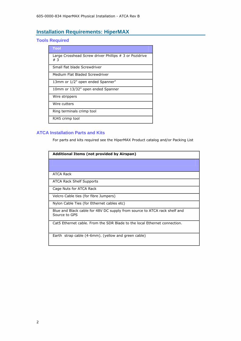
Tools Required
Tool
Large Crosshead Screw driver Phillips # 3 or Pozidrive # 3
Small flat blade Screwdriver
Medium Flat Bladed Screwdriver
13mm or 1/2" open ended Spanner"
10mm or 13/32" open ended Spanner
Wire strippers
Wire cutters
Ring terminals crimp tool
RJ45 crimp tool
ATCA Installation Parts and Kits
For parts and kits required see the HiperMAX Product catalog and/or Packing List
Additional Items (not provided by Airspan)
ATCA Rack
ATCA Rack Shelf Supports
Cage Nuts for ATCA Rack
Velcro Cable ties (for fibre Jumpers)
Nylon Cable Ties (for Ethernet cables etc)
Blue and Black cable for 48V DC supply from source to ATCA rack shelf and Source to GPS
Cat5 Ethernet cable. From the SDR Blade to the local Ethernet connection.
Earth strap cable (4-6mm). (yellow and green cable)

Physical Installation - HiperMAX
3
14 Slot ATCA Shelf

605-0000-834 HiperMAX Physical Installation - ATCA Rev B
4
Shelf Overview
ATCA Chassis
The 14-slot ATCA chassis conforming to the PICMG 3.0 specification is detailed below. The chassis has a dual star backplane with up to two Shelf Managers, fans, fan controllers, filters and power conditioning modules.
Shelf Manager
The 14-slot chassis has bussed IPMBs and is designed to work with Shelf Managers that are located in the dedicated Shelf Manager slots. The Shelf Manager also contains the Fan Controller for the three pluggable fan trays. If only one Shelf Manager is installed is should be installed in the upper slot.
Fan Trays
Three modular fan trays can easily be removed after removing the fan tray cover at the front of the shelf. The display module at the front of the fan tray provides a blue hot-swap LED, amber and red alarm LEDs and a green fan-try-good LED as well as a hot swap push button.
Shelf Alarm Panel
Note: This functionality is not currently supported within the HiperMAX system.
Power Distribution
There are two pluggable PEMs (Power Entry Modules). Each PEM provides power terminals for a
25A power feed ( -48V and VRTN). Internally to the PEM these are split into four separate fused feeds, each of these four feeds is protected by two 30A fuses. The minimum input voltage is -40.5VDC and the maximum is -57.0VDC.
Blades
Two blades are currently available. SDR Blade for the software defined radio and Switch for the Ethernet Switch.

Physical Installation - HiperMAX
5
ESD Protection
The ESD Wrist Strap terminal is located on the upper front side of the shelf, and must be used prior to working on any part or electronic component.
Installation Checks
Before inserting any blades, turn on the -48V and measure the voltage on the PEMs. Note when the chassis are powered the fans go to full speed and then slow down once the Shelf Manager control loop kicks in. If the -48V is connected the wrong way the chassis will not power up.
605-0000-834 HiperMAX Physical Installation - ATCA Rev B
6
Install 14 Slot ATCA Shelf
This procedure should be used in conjunction with the Schroff 14 Slot ATCA Manual 11596-006
The 13U shelf can be fitted in a standard ATCA Rack or into a standard 19" Rack using adapters.
1. Place Shelf supports at the height of the base of the ATCA Shelf into the sides of the ATCA rack. Fixing the supports will be dependant on ATCA Rack used.
2. Slide the shelf into position and secure into the front of the rack with eight retaining M6
screws and nylon washers.
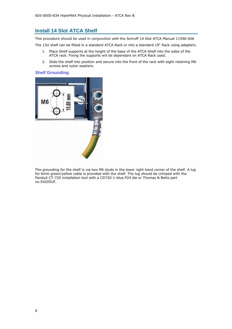
Shelf Grounding
The grounding for the shelf is via two M6 studs in the lower right hand corner of the shelf. A lug for 6mm green/yellow cable is provided with the shelf. The lug should be crimped with the Panduit CT-720 installation tool with a CD720-1-blue P24 die or Thomas & Betts part no.54205UF.

Physical Installation - HiperMAX
7
Shelf Alarm Panel (SAP)
The shelf alarm panel is usually fitted to the top left or top right of the chassis. It provides two serial connection ports, alarm indication and an interface to Telco alarm systems.
Note: This functionality is not currently supported within the HiperMAX system.
Shelf Manager
Location
The shelf manager location is dependant on the switch position in the shelf. Unless the shelf manager is placed in the correct slot communication is not possible with the switch using the shelf manager. If the switch is in position 7 then the shelf manager should be in position 1 and if the switch is in position 8 then the shelf manager should be in position 2.
Faceplate
1. Fixing screw
2. ETH 1 Link/Activity LED (green) :
on = link,
off = no link,

605-0000-834 HiperMAX Physical Installation - ATCA Rev B
8
blinking = link + activity
3. ETH 1 Speed (yellow) :
on = 100 Mb,
off = 10 Mb
4. ETH 0 Speed (yellow) :
on = 100 Mb,
off = 10 Mb
5. ETH 0 Link/Activity LED (green) :
on = link,
off = no link,
blinking = link + activity
6. ETH 0 Ethernet service connector
7. Reset push button
8. Shelf manager status LED (red) : red = out of service
9. Shelf manager status LED (green) :
on = in service, active,
blinking = in service, backup shelf manager
10. Hot swap LED (blue) :
on = board may be extracted,
long blink = initialising,
short blink = deactivating (hot swap requested but not ready),
off = board active, do not extract
11. Hot swap handle. Half pulled to initiate hot swap request sequence, and await the hot swap LED arriving at permanently on state. Thereafter, fully pulled to extract board
12. Hot swap switch. Activated by half pull of the hot swap handle. Directs whether hot swap is requested, or activation is requested.
Connecting to the Shelf Manager
Access to the shelf manager is via:
Shelf Manager serial connection (LAT): (This port is on the Alarm panel). This provides access to all shelf manager configuration tools except the web interface. It allows manipulation of the shelf manager at all levels including the boot prompt, Linux command line and the shelf manager command line interface.
Local IP address: provides access to all shelf manager configuration tools except boot prompt. environment variables. The ipaddress, netmask and gateway must be configured using the LAT connection before access is possible.
Network IP Access: provides access to all shelf manager configuration tools except boot prompt. environment variables. The ipaddress, netmask and gateway must be
configured using the LAT connection before access is possible.
Communicating with the Shelf Manager
Communication with the shelf manager is either by:
Linux command line.
ARM boot environment.
Shelf manager command line interface.
or
Shelf manager web interface.

Physical Installation - HiperMAX
9
General Configuration
Jumper settings
Access to all shelf manager configuration tools except boot prompt shelf manager may be either through the front of the shelf manager or network access through the backplane.
a) Jumper Settings for Connection to front of Shelf Manager

605-0000-834 HiperMAX Physical Installation - ATCA Rev B
10
b) Jumper Settings for Connection to Switch via backplane
Single/dual Redundancy
A managed HiperMAX shelf may be configured with either a single or dual redundant shelf managers.
Five possible configuration procedures exist.
Commissioning procedures
For configuration details see 605-0000-837 HiperMAX Commissioning/ Shelf Manager Configuration
Configure a single shelf manager.
Configure dual redundant shelf managers.
Modifications to an existing configuration
For configuration details see 605-0000-840 HiperMAX System Maintenance/Shelf Manager Operations
Remove the redundant shelf manager.
Add a shelf manager to introduce redundancy.
Replace an unhealthy shelf manager.

Physical Installation - HiperMAX
11
Fan Trays
The 14 slot ATCA shelf contains three interchangeable fan trays. The fan trays are plugged-in at the front bottom of the shelf and can be removed after lifting the front cable tray.
1. Hot Swap push button
2. Hot Swap LED (blue)
3. Fan Tray Alarm LED (red)
4. Fan Tray OK LED (green)
Inserting the fan unit
1. Raise the cable tray to allow access to the slots.
2. Slide the fan tray into the guides until fully home.
3. Secure with the two fixing screws at the base of the unit.
4. The fans automatically start when the power is applied to the rack. The shelf manager regulates the fan speed.
5. When the fan is up to speed the fan OK LED set to green.
Removing the fan unit
1. Raise the cable tray to allow access to the fans.
2. Press the 'Hot Swap' push button to initiate hot swap request sequence, and await the hot swap LED (blue) arriving at permanently on state. Unscrew the
fixing screws and fully extract the unit using the extraction handle.
Hot Swap LED (blue)
on board may be extracted
long blink
initialising
short blink
deactivating (hot swap requested but not ready)
off board active, do not extract

605-0000-834 HiperMAX Physical Installation - ATCA Rev B
12
Air Filter
1. Raise the cable tray to allow access to the filter.
2. To install, push the air filter into the guide rails at each side of the shelf until the spring mounted ball lock engage. When installing the air filter, the filter element must be in top position.

Physical Installation - HiperMAX
13
Cable Tray
The cable tray is designed to be raised when access to the fan tray is required.
The figure below shows the cable tray in the normal position and raised positions.
Normal Position Raised Position
Fitting the Cable Tray
1. Place the cable tray over the two studs at the sides of the shelf.
2. Secure using the four domed nuts provided.
3. Check for correct installation. In the raised position the filter tray should be able to be extracted

605-0000-834 HiperMAX Physical Installation - ATCA Rev B
14
5 Slot ATCA Shelf

Physical Installation - HiperMAX
15
Install ATCA Shelf
The 5-slot ATCA chassis conforming to the PICMG 3.0 specification and fits in a 5U space within an ATCA rack.
This procedure should be used in conjunction with the Schroff 5 Slot ATCA manual 11596-009
The 5U shelf can be fitted in a standard ATCA rack or into a standard 19" Rack using adapters.
1. Place shelf supports at the height of the base of the ATCA shelf into the sides of the ATCA rack. Fixing the supports will be dependant on ATCA rack used.
2. Slide the shelf into position and secure into the front of the rack with four retaining M6 screws and nylon washers.
Shelf Grounding
The grounding for the shelf is via two M6 studs in the lower right hand corner of the shelf. A lug for 6mm green/yellow cable is provided with the shelf. The lug should be crimped with the Panduit CT-720 installation tool with a CD720-1-blue P24 die or Thomas & Betts part no.54205UF.

605-0000-834 HiperMAX Physical Installation - ATCA Rev B
16
Shelf Manager
Faceplate
1. Fixing screw
2. ETH 1 Link/Activity LED (green) :
on = link,
off = no link,
blinking = link + activity
3. ETH 1 Speed (yellow) :
on = 100 Mb,
off = 10 Mb
4. ETH 0 Speed (yellow) :
on = 100 Mb,
off = 10 Mb
5. ETH 0 Link/Activity LED (green) :
on = link,
off = no link,
blinking = link + activity
6. ETH 0 Ethernet service connector
7. Reset push button
8. Shelf manager status LED (red) : red = out of service
9. Shelf manager status LED (green) :
on = in service, active,
blinking = in service, backup shelf manager
10. Hot swap LED (blue) :
on = board may be extracted,
long blink = initialising,
short blink = deactivating (hot swap requested but not ready),
off = board active, do not extract
11. Hot swap handle. Half pulled to initiate hot swap request sequence, and await the hot swap LED arriving at permanently on state. Thereafter, fully pulled to extract board
12. Hot swap switch. Activated by half pull of the hot swap handle. Directs whether hot swap is requested, or activation is requested.

Physical Installation - HiperMAX
17
Connecting to the Shelf Manager
Access to the shelf manager is via:
Shelf Manager serial connection (LAT): This Interface is on the CDM Tray and provides access to all shelf manager configuration tools except the web interface. It allows manipulation of the shelf manager at all levels including the boot prompt, Linux command line and the shelf manager command line interface.
Local IP address: provides access to all shelf manager configuration tools except boot prompt. environment variables. The ipaddress, netmask and gateway must be configured using the LAT connection before access is possible.
Network IP Access: provides access to all shelf manager configuration tools except boot prompt. environment variables. The ipaddress, netmask and gateway must be configured using the LAT connection before access is possible.
Communicating with the Shelf Manager
Communication with the shelf manager is either by:
Linux command line.
ARM boot environment.
Shelf manager command line interface.
or
Shelf manager web interface.
General Configuration
A managed HiperMAX shelf may be configured with either a single or dual redundant shelf managers.
Five possible configuration procedures exist.
Commissioning procedures
For configuration details see 605-0000-837 HiperMAX Commissioning/ Shelf Manager Configuration
Configure a single shelf manager.
Configure dual redundant shelf managers.
Modifications to an existing configuration
For configuration details see 605-0000-840 HiperMAX System Maintenance/Shelf Manager Operations
Remove the redundant shelf manager.
Add a shelf manager to introduce redundancy.
Replace an unhealthy shelf manager.

605-0000-834 HiperMAX Physical Installation - ATCA Rev B
18
Fan Trays and Filter
Fan
The 5 Slot ATCA Shelf contains a interchangeable Fan Tray. The Fan Tray is plugged-in at the
right front side of the Shelf.
To install the Fan slide into the shelf guides and retain with the two front panel screws.
Filter
To install the air filter push it into the guide rails at each side of the shelf until the spring mounted ball lock engage.
Replace filters as required.
Physical Installation - HiperMAX
19
Power
Hazardous voltage!
Before working ensure that the power is removed from the power connection cables. When the system is powered on, do NOT touch
the power terminals.
48 Volt Breakers and Distribution
DC Feeds should be provided as follows:
The Shelf, SCRTs and GPS can be powered using a regular telecommunication power supply of -
48VDC with a VDC return. The specified voltage range is from -40.5 VDC to -57.0 VDC.
ATCA Shelves
2 supply feeds per shelf. Each supply should be fed from a separate breaker.
GPS
2 supply feeds per shelf. Each supply should be fed from a separate breaker.
SCRT
1 supply feed per SCRT
DC Feeds to PEM Modules
Warning!
14 slot Chassis: Although there are fuses in the power entry circuit of the Shelf, the power lines have to be
protected on rack level with 80A breakers.
5 slot Chassis: Although there are fuses in the power entry circuit of the Shelf, the power lines have to be protected on rack level with 30A breakers.
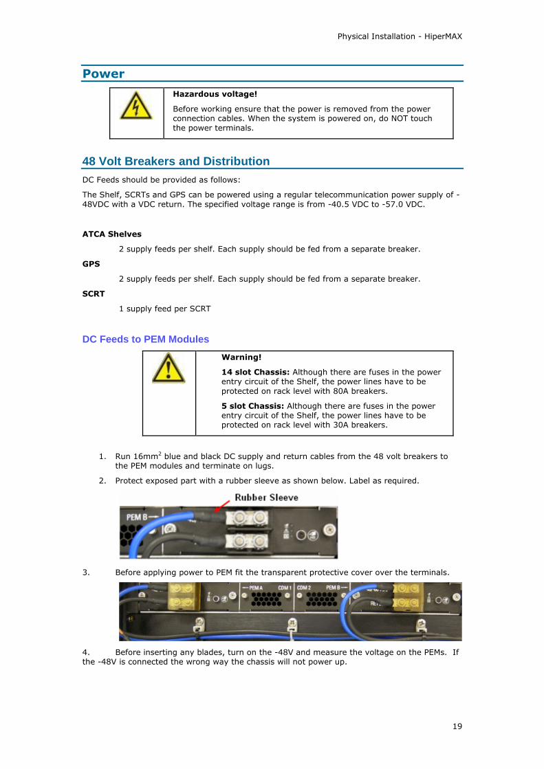
1. Run 16mm2 blue and black DC supply and return cables from the 48 volt breakers to the PEM modules and terminate on lugs.
2. Protect exposed part with a rubber sleeve as shown below. Label as required.
3. Before applying power to PEM fit the transparent protective cover over the terminals.
4. Before inserting any blades, turn on the -48V and measure the voltage on the PEMs. If the -48V is connected the wrong way the chassis will not power up.
605-0000-834 HiperMAX Physical Installation - ATCA Rev B
20
Power Entry Modules
Power Entry Modules
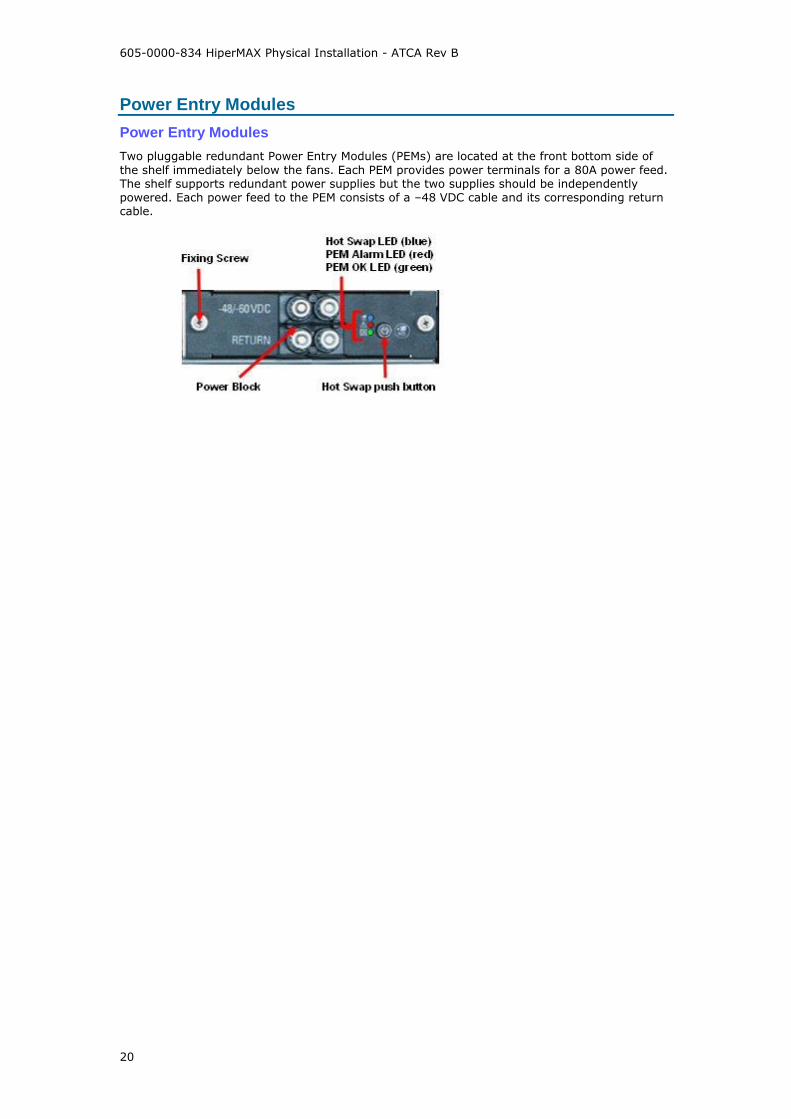
Two pluggable redundant Power Entry Modules (PEMs) are located at the front bottom side of
the shelf immediately below the fans. Each PEM provides power terminals for a 80A power feed. The shelf supports redundant power supplies but the two supplies should be independently powered. Each power feed to the PEM consists of a –48 VDC cable and its corresponding return cable.
Physical Installation - HiperMAX
21
Fibre Cables and Cable Management
Fibre Cabling
Fibre Termination Shelf
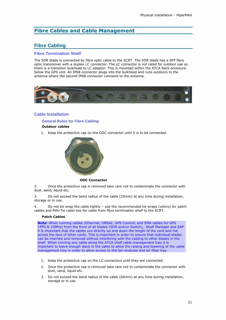
The SDR blade is connected by fibre optic cable to the SCRT. The SDR blade has a SFP fibre optic transceiver with a duplex LC connector. The LC connector is not rated for outdoor use so there is a transition bulkhead to LC adaptor. This is mounted within the ATCA Rack enclosure below the GPS unit. An IP68 connector plugs into the bulkhead and runs outdoors to the
antenna where the second IP68 connector connects to the antenna.
Cable Installation
General Rules for Fibre Cabling
Outdoor cables
1. Keep the protective cap on the ODC connector until it is to be connected.
ODC Connector
2. Once the protective cap is removed take care not to contaminate the connector with dust, sand, liquid etc.
3. Do not exceed the bend radius of the cable (25mm) at any time during installation, storage or in use.
4. Do not tie wrap the cable tightly – use the recommended tie wraps (velcro) for patch
cables and Milli-Tie cable ties for cable from fibre termination shelf to the SCRT.
Patch Cables
Note: When running cables (Ethernet; OBSAI; GPS Control; and SMA cables for GPS 1PPS & 10MHz) from the front of all blades (SDR and/or Switch), Shelf Manager and SAP it is important that the cables run directly up and down the length of the card and not across the face of other cards. This is important in order to ensure that individual blades can be inserted and removed without interfering with the cabling to other blades in the shelf. When running any cable along the ATCA shelf cable management tray it is important to leave enough slack in the cable to allow the raising and lowering of the cable management tray in order to allow access to the fan modules and air filter tray.
1. Keep the protective cap on the LC connectors until they are connected.
2. Once the protective cap is removed take care not to contaminate the connector with dust, sand, liquid etc.
3. Do not exceed the bend radius of the cable (60mm) at any time during installation, storage or in use.

605-0000-834 HiperMAX Physical Installation - ATCA Rev B
22
4. Do not tie wrap the cable tightly – use the Velcro ties such as RS Stock Codes 333-9777 (5m reel) or 333-9648 (individual ties) .
5. When inserting the LC connectors to the SFP modules there should be an audible click. Then pull gently to ensure it is connected correctly.
Fibre Cabling
1. Secure the cable termination shelf in the ATCA rack below the GPS using four screws and nylon cup washers.
2. Attach the bulkhead interface by passing through the hole from the rear and securing with the large hexagonal nut.
3. Run the ODC Fibre cable from the SCRT to the fibre termination shelf.
4. Secure the cable using Milli-Tie cable ties. (See Cable Ties)
5. Excess cable should be coiled to prevent damage. Do not exceed the bend radius of the cable (25mm).
6. Terminate the fibre cable at the SCRT.
7. Terminate the fibre cable at the rear of the bulkhead interface on the cable terminating shelf. Label with SCRT Id.
8. Run a patch cable from the cable termination shelf to the SDR blade. Support the cable using the cable tray (see Cable Tray).
9. Loop excess cable in the clips at the side of the rack. Avoid sharp bends in the fibre (60mm bend radius).
10. The fibre should secured and be attached to the cable tray using velcro ties.

Physical Installation - HiperMAX
23
Cable Ties
Outdoor Cables
Airspan recommends that cables should be secured with Milli-Tie cables as these are designed to
prevent over-tightening of cable ties. Over-tightening of cable ties may causes damage and degrade system performance.
The Milli-Tie can be used to secure cables in the same manner as normally used for nylon straps. The steps below show the basic use of the product.
A Single Basic Wrap
Place the Mille-Tie around the target, and thread the tongue through the last LARGE aperture in the rearmost cell.
Pull or slide the Mille-Tie onto the target. Note that the Mille-Tie stretches to cushion the installation.
Release the tension when snug, then cut and remove any excess strip. Always cut through the square sections, not the wider cells.
605-0000-834 HiperMAX Physical Installation - ATCA Rev B
24
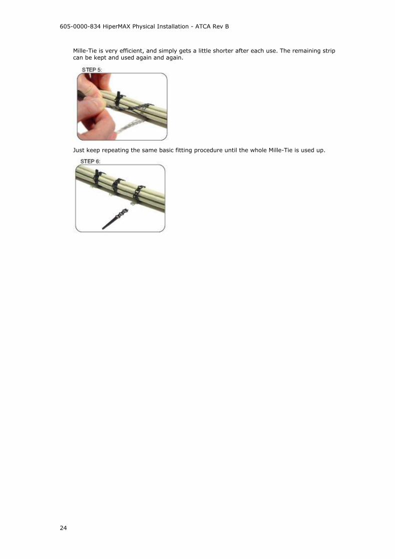
Mille-Tie is very efficient, and simply gets a little shorter after each use. The remaining strip can be kept and used again and again.
Just keep repeating the same basic fitting procedure until the whole Mille-Tie is used up.

Physical Installation - HiperMAX
25
Blades
Install HiperMAX SDR Blade
Danger of electrostatic discharge! Static electricity can harm delicate components inside the shelf. An ESD wrist strap must be worn before
exchanging any part or electric component! The ESD wrist strap terminal (4 mm banana jack) is located at the upper front side of the shelf.
Note: For instructions on board insertion removal and replacement see Board
Insertion/Removal/Replacement
The SDR blade is designed to plug into an ATCA chassis. The SDR‟s architecture is based on configurable elements to allow for changes in specification i.e. software defined radio.
The SDR blade transports data over a fibre optic connection to the transceiver using OBSAI RP3-01 interface running at 768Mbps for the SCRT and 3.072Gbps for the MCRT.
SDR Blade Front panel
Item Description
ATCA – hot swap handle See Board Insertion/Removal/Replacement
ATCA – hot swap LED H/S Once the extraction levers are released a flashing blue LED indicates card de-activation
requested.
Blue solid on indicates card de-activated and now safe to remove. Allow 30 seconds to close file systems.
605-0000-834 HiperMAX Physical Installation - ATCA Rev B
26
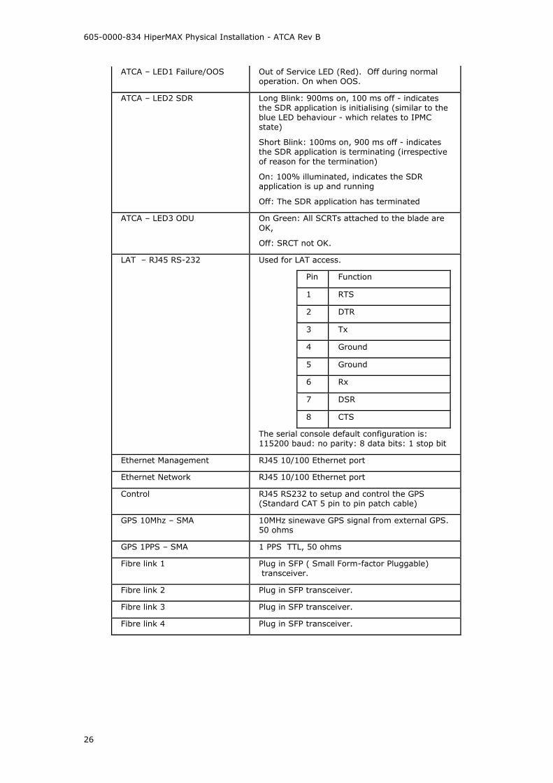
ATCA – LED1 Failure/OOS Out of Service LED (Red). Off during normal operation. On when OOS.
ATCA – LED2 SDR Long Blink: 900ms on, 100 ms off - indicates the SDR application is initialising (similar to the blue LED behaviour - which relates to IPMC state)
Short Blink: 100ms on, 900 ms off - indicates the SDR application is terminating (irrespective
of reason for the termination)
On: 100% illuminated, indicates the SDR application is up and running
Off: The SDR application has terminated
ATCA – LED3 ODU On Green: All SCRTs attached to the blade are
OK,
Off: SRCT not OK.
LAT – RJ45 RS-232 Used for LAT access.
Pin Function
1 RTS
2 DTR
3 Tx
4 Ground
5 Ground
6 Rx
7 DSR
8 CTS
The serial console default configuration is: 115200 baud: no parity: 8 data bits: 1 stop bit
Ethernet Management RJ45 10/100 Ethernet port
Ethernet Network RJ45 10/100 Ethernet port
Control RJ45 RS232 to setup and control the GPS (Standard CAT 5 pin to pin patch cable)
GPS 10Mhz – SMA 10MHz sinewave GPS signal from external GPS. 50 ohms
GPS 1PPS – SMA 1 PPS TTL, 50 ohms
Fibre link 1 Plug in SFP ( Small Form-factor Pluggable) transceiver.
Fibre link 2 Plug in SFP transceiver.
Fibre link 3 Plug in SFP transceiver.
Fibre link 4 Plug in SFP transceiver.

Physical Installation - HiperMAX
27
Install
On successful completion of this process, the SDR board will be
inserted into the correct slot in the ATCA rack as specified by the job sheet.
connected to the 1PPS and 10MHz signals from the GPS module if specified to do this by the job sheet.
connected to manage the GPS module if specified to do this by the job sheet.
configured with Base Station ID (BSID) as specified in the job sheet.
configured with network parameters as specified in the job sheet.
configured to send events to the designated Netspan server as specified in the job sheet.
configured to send and receive network traffic from either an external switch or a switch which is plugged in and configured in the ATCA rack as specified by the job sheet.
connected to an external Ethernet switch if specified by the job sheet.
connected to one or more SCRTs as specified by the job sheet. Communications
between SDR blade and the SCRTs will be verified.
manageable from the Netspan server specified by the job sheet.
Job Sheet
Prior to commencement of this procedure, the installer should have a job sheet available. This should include the following information:
BS location and ATCA rack identity
Whether the system is required to be locked to a GPS timing reference.
Whether the SDR is to be a Primary Master, Secondary Master or a Slave. This
information will be mapped to the ATCA rack slot number by this procedure.
A BSID is required for each SDR Blade. This should be in a format xxxxxx:xxxxxx where x is a decimal digit.
The mapping of SCRT ID to Obsai port ID on the SDR blade.
Network configuration information for the SDR blade. This shall include the following information for the front panel and the backplane.
o Traffic Port : Defines whether traffic is via the front panel of the "SDR blade", "Primary Backplane" or "Secondary backplane".
o IP Address : Should only be set if "Management IP Mode" is set to "Static IP Address" See below for "Management IP Mode" parameter.
o Netmask : Should only be set if "Management IP Mode" is set to "Static IP Address" See below for "Management IP Mode" parameter.
o Default Gateway : Should only be set if "Management IP Mode" is set to "Static IP Address" See below for "Management IP Mode" parameter.
o Management VLAN : Specified as either "Untagged" or "Tagged"
o Management VLAN Tag : Should only be set if "Management VLAN" is set to "Tagged"
o Management IP Mode : Specified as "Static IP Address" or "Obtain IP Address via DHCP"
o Ethernet Mode : Specified as "Autonegotiate" or "Fixed"
o Ethernet Rate : Need only be configured if "Ethernet Mode" is set to "Fixed". Specified as "10M" or "100M".
o Ethernet Duplex : Need only be configured if "Ethernet Mode" is set to "Fixed". Specified as "Full" or "Half"
SNMP configuration information. This will allow events from the BS to arrive at the specified Netspan server. This will include the following information:
o Read Only Community : This should be specified to the same value as in Netpan's Discovery Parameters. (Found under "Server" on Netspan's left hand panel).

605-0000-834 HiperMAX Physical Installation - ATCA Rev B
28
o Read Write Community : This should be specified to the same value as in Netpan's Discovery Parameters. (Found under "Server" on Netspan's left hand panel).
o SNMP Port Number : This should be specified to the same value as in Netpan's Discovery Parameters. (Found under "Server" on Netspan's left hand panel).
o IP Address : This specifies Netspan's IP address (Found under "Server Global Configuration" which is under "Server" on Netspan's left hand panel).
o Community : Normally specified to the same value as for "Read Only Community"
o Port Number : Normally specified to a value of 9023.
Whether the Primary Master blade or the Secondary Master blade manages the GPS module.
NTP configuration
o This specifies a list of NTP servers.

Physical Installation - HiperMAX
29
Install Ethernet Switch
Danger of electrostatic discharge! Static electricity can harm delicate components inside the Shelf. An ESD wrist strap must be worn before exchanging any part or electric component! The ESD Wrist Strap Terminal (4 mm banana jack) is located at the upper front side of the Shelf.
Note The ATCA Ethernet switch from Airspan is optional and is normally only supported by in the 14 slot ATCA shelf. 5 slot systems will be supplied with an external rack mount Ethernet VLAN switch with connections to the SDR cards via 100baseT front panel ports.
The SDR blade has two 100BaseT RJ-45 connectors on the front panel, the Ethernet signals are also routed over the backplane to the two centre slots of the ATCA shelf. This allows Ethernet to be passed to an external switch or to the ATCA based Ethernet switch.
Install ATCA Ethernet switch
This describes the installation of the Airspan ATCA Ethernet Switch. The Ethernet switch card is placed in physical slot 7 (logical slot 1) of 14 slot chassis.
Connection to the network infrastructure is via ports 17-22 on the front panel using a suitable patch cable. The port supports 1Gbit Ethernet operation for which at least a CAT5e cable is required.
Using a Network cable connect the designated port on the front of the switch blade to the network.

605-0000-834 HiperMAX Physical Installation - ATCA Rev B
30
Blade Insertion/Removal/Replacement
Danger of electrostatic discharge! Static electricity can harm delicate components inside the Shelf. An ESD wrist strap must be worn before exchanging any part or electric component! The ESD Wrist Strap Terminal (4 mm banana jack) is located at the upper front side of the Shelf.
Board Insertion
1. To insert the blades – engage the “hooks” on both handles, and rotate both handles simultaneously towards the face of the blade to force the blade back into the chassis.
2. Secure blade by tightening screws top and bottom.
3. Pinch the spring lever to raise the finger and push hot swap handle home through the faceplate. Release the spring lever to lower and retain the handle. Failure to do this will erode the plastic and permit the handle to release easily.

Physical Installation - HiperMAX
31
Board Removal / Hot Swapping
Note: GPS 10M and 1Hz connections. The 10M and 1Hz should not be removed from a live
system. If the primary or secondary GPS SDRs are to be removed the hot swap handle on the SDR should be activated, once the blue light is on (not flashing) the GPS cables can be removed.
1. When a card is to be replaced, release the hot swap handle by rotating the upper part of the handle to the position shown in Figure 2 below.
Figure 1: Hot Swap Handle: Normal
Figure 2: Hot Swap Handle: Released (Hot Swap Initiated)
2. The H/S blue light flashes – when it stops flashing and is permanently on the board can be removed by unscrewing the top and bottom screws and rotating both upper and lower handles forward to disengage card.

605-0000-834 HiperMAX Physical Installation - ATCA Rev B
32
Hot swap LED (blue)
on board may be extracted
long blink
initialising
short blink
deactivating (hot swap requested but not ready)
off board active, do not extract

Physical Installation - HiperMAX
33
GPS
Install GPS Receiver
Overview
For TDD and smart antenna operation the base stations need to be locked to GPS timing. The ATCA shelf has a synchronisation clock interface that is connected to all 14 blades in the Shelf.
The GPS reference is generated by the GPS shelf. Each SDR blade locks onto the 10MHz signal
to align with the GPS clock. The GPS module outputs 10MHz(10M) and 1pps (1Hz) signals.
The SDR blades are able to operate in stand alone mode and have a GPS input on the front panel. In order to allow clock redundancy, the GPS signals are fed to two blades. The SDRs that have GPS connected are selected via Netspan – one is selected as the master the other as standby. The master SDR blade drives the 10MHz GPS clock signal onto the backplane signal CLK3A. The standby blade drives the GPS clock onto CLK3B. Each SDR card in the system monitors CLK3A and CLK3B. One of these is selected to drive the boards PLL and derive the clocks. If one of the SDR boards fail or the GPS is unplugged or the blade is removed, the SDR blades will then switch to the other clock source. If both CLK3A and CLK3B fail then the PLLs free run.
The GPS Receiver Parts
Supplied Parts Quantity
2U 19" GPS Receiver
1
SMA to SMA Sync Cables
4
RJ45-RJ45 Control Cable: Standard CAT5 Pin to pin patch cable
1

605-0000-834 HiperMAX Physical Installation - ATCA Rev B
34
Other Required Parts
GPS Antenna
(choose from)
TA-200 Antenna for feeder
installation up to 35m from SDR
Trimble Bullet 3 Antenna for feeder installation up to 60m from SDR
Antenna Feeder Cable (choose from)
RG58 For runs up to 20 metres
RG213 For runs up to 60 metres
Surge Protector Polyphasor or simular
Installation
The GPS shelf is currently available as a standard 2u 19inch shelf. It is usual to place the GPS receiver at the top of the rack.
Installation Steps
Note: When running cables (Ethernet; OBSAI; GPS Control; and SMA cables for GPS 1PPS & 10MHz) from the front of all blades (SDR and/or Switch), Shelf Manager and SAP
it is important that the cables run directly up and down the length of the card and not across the face of other cards. This is important in order to ensure that individual blades can be inserted and removed without interfering with the cabling to other blades in the shelf. When running any cable along the ATCA shelf cable management tray it is important to leave enough slack in the cable to allow the raising and lowering of the cable management tray in order to allow access to the fan modules and air filter tray.
Secure the shelf in the rack using screws into the cage nuts (Screws and nuts not provided by Airspan.)

Physical Installation - HiperMAX
35
Run two 1.5mm Blue and Black DC feeds and returns from the 48 volt breakers to the GPS unit.
Terminate and connect on the -48V to the A and B terminals.
Connect 10M and 1Hz using the jumper cables provided to the corresponding terminals on the primary master.
Connect 10M and 1Hz using the jumper cables provided to the corresponding terminals on the secondary master.
Connect the CNTRL cable from the GPS shelf to the CNTRL port on the primary master.
Connect the antenna feeder cable to the shelf.


37
How to find out more
about
Airspan products
and solutions
Airspan has offices in the following countries:
Europe
Czech Republic
Poland
Russia
United Kingdom
Africa
South Africa
Americas
United States
Asia Pacific
Australia
China
Indonesia
Japan
New Zealand
Philippines
Sri Lanka
For more information about Airspan, its products and solutions, please visit our Web site:
www.airspan.com
Or write to us at one of the addresses below.
We will be delighted to send you additional
information on any of our products and their
applications around the world.
Worldwide Headquarters: Airspan Networks Inc. 777 Yamato Road, Suite 105 Boca Raton, Florida 33431-4408 USA Tel: +1 561 893 8670 Fax: +1 561 893 8671
Main Operations: Airspan Communications Ltd.
Cambridge House, Oxford Road,
Uxbridge, Middlesex UB8 1UN
UK
Tel: +44 (0) 1895 467 100
Fax: +44 (0) 1895 467 101