history of construction - ash pond - alabama power · ponds are utilized alternately while dredging...
TRANSCRIPT
HISTORY OF CONSTRUCTION FOR EXISTING CCR SURFACE IMPOUNDMENT
PLANT GASTON ASH POND
40 CFR 257.73(c)(1)(i)‐(xii)
(i) Site Name and Ownership Information:
Site Name: E.C. Gaston Steam Plant
Site Location: Wilsonville, Alabama
Site Address: 31972 Highway 25
Wilsonville, Alabama 35186
Owner: Alabama Power Company
Owner Address: 600 North 18th Street
Birmingham, AL 35203
CCR Impoundment Name: Plant Gaston Ash Pond
NID ID: N/A
EPA’s “Disposal of Coal Combustion Residuals from Electric Utilities” Final Rule (40 C.F.R. Part 257 and Part 261), §257.73(c)(1), requires the owner or operator of an existing CCR surface impoundment to compile a history of construction. To the extent feasible, the following information is provided:
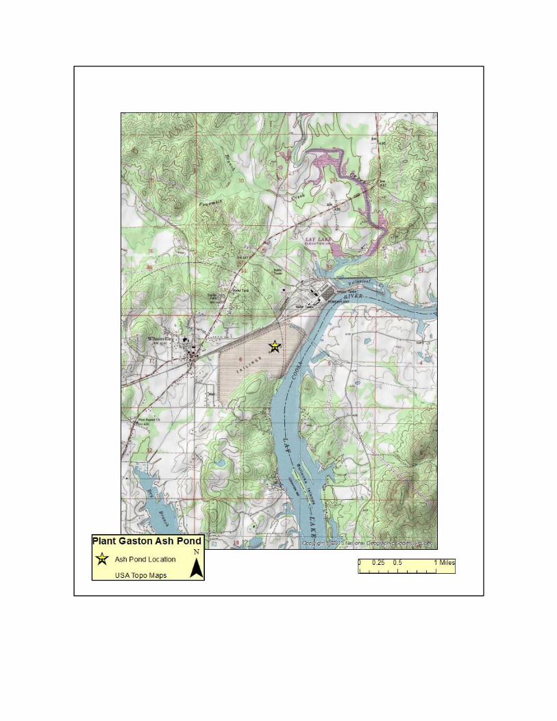
(ii) CCR Unit Location Map:
33°14'02"N, 86°28'22"W
See Location Map in the Appendix
(iii) Purpose of CCR Impoundment: The E.C. Gaston Steam Plant is a 5 unit electric generating facility;
Units 1‐4 were originally coal‐fired units but are were recently converted to gas–fired units with the
ability to be coal‐fired, while Unit 5 remains a coal‐fired only. The Plant Gaston Ash Pond is designed to
receive and store coal combustion residuals produced during the electric generating process at Plant
Gaston, along with low‐volume wastes and stormwater sump flows from the plant.
(iv) Watershed Description: Plant Gaston is located within both the Lower Yellowleaf Creek HUC‐12
watershed which has a total area of 29,120 acres and the Hay Spring Branch HUC‐12 watershed which
has a total area of 27,197 acres. The ash pond unit is located entirely within the Hay Spring Branch
watershed. Both the Lower Yellowleaf Creek and Hay Spring Branch watersheds are located within
within the Lower Coosa HUC‐8 watershed which has a drainage area of 1,255,891 acres. Only a relatively
nominal portion of flow from the surrounding watershed flows into the pond.
(v) Description of physical and engineering properties of CCR impoundment foundation/abutments:
The foundation soils beneath the impoundment are comprised of residuum of dolomite, limestone and
shale, typically classified as highly plastic clays and silty clays. Bedded chert and chert boulders are
encountered in some areas. Based on borings conducted prior to construction of the impoundment, the
elevation of the top of the underlying bedrock ranges from 380 feet to 410 feet (approx.). The geologic
properties of the site are characterized by carbonate rocks of the Knox Group of the Cambrian and
Ordovician age. When weathered, the carbonate rocks can yield cherty residual clay or incipient karst
type topography. Visible karst topography has not been noted within the ash pond.
(vi) Summary of Site Preparation and Construction Activities: The Ash Pond was originally constructed
in the early 1950’s. The basin was formed by excavating predetermined zones to elevations ranging from
389 ft to 418 ft, with much of the center zone having no excavation. Maximum elevations in the center
zone were approximately 420 ft.
Material for the embankment construction was excavated from within the ash pond area adjacent to
the embankments. The dike fill material consists mainly of clay. The depth of the fill extends up to
depths of approximately 50 feet at its deepest. The South Dike was constructed at an elevation of 445
ft, but has been raised as high as 449 ft in some areas. It has a maximum height of approximately 50
feet. The West Dike was constructed at an elevation of 445 ft with a maximum height of 30 ft. The
North Dike was constructed at elevations up to 445 ft, with later raises bringing it to a maximum
elevation of 447 ft. It has a maximum height of 25 ft. The exterior slopes are 2.5:1 on the east dike and
2:1 on the west and north dikes. The interior slopes are 2.5:1 on the east dike and 1.5:1 on the west and
north dikes. Efforts to widen the dikes have included adding fill to the slopes to maintain their original
geometry.
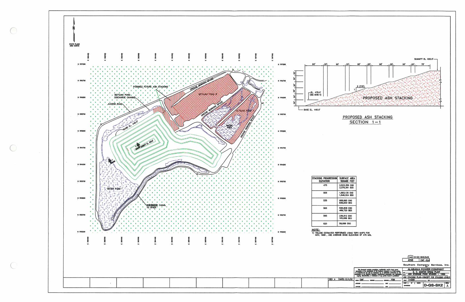
In the late 1980’s, the impoundment was reconfigured to the arrangement that is currently used (see
Appendix). Ash is sluiced into one of two settling ponds located at the eastern edge of the pond. When
one cell fills, the sluice is diverted to the alternate cell while the filled cell is dredged. The dredged ash is
conditioned and dry stacked further west in the pond. The sluice water, after leaving the settling pond,
is diverted to a canal that runs along the perimeter of the pond boundary to another low energy area at
the western pond edge where further settling of fines takes place. From there, the water enters another
canal which leads to the discharge structure located at the Coosa River.
Additional construction undertaken since the initial efforts in the 1950’s include widening of the dike,
especially along the eastern edge of the pond. The widening to its current geometry was achieved by
adding a layer of clay to the downstream face of the dike, and by adding fill material to the sluiced ash
on the upstream side. This resulted in a dike raise of up to four feet in some areas. The area between
the northeastern dike slope and the dike built to comprise the western edge of the coal pile was also
filled over the years. The fill is comprised of miscellaneous soils including clays, gravelly clays and silts,
and isolated boulders.
(vii) Engineering Diagram:
The following drawings reflecting the construction of the Plant Gaston Ash Pond can be found in the
Appendix:
Typical Section – South Dike
Typical Section – North and West Dikes
Typical Section – Adjacent to Coal Pile
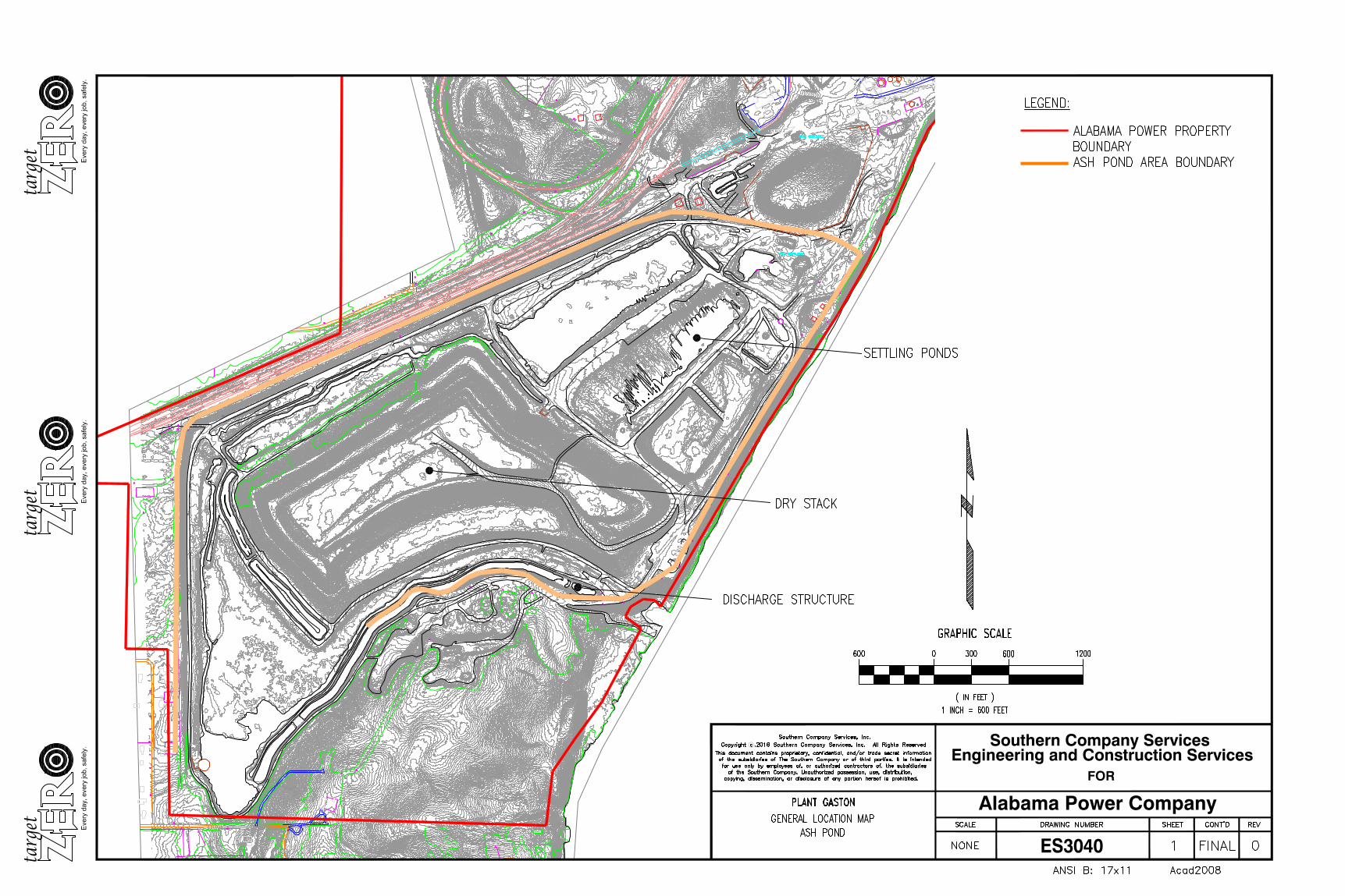
2000 Ash Stacking Plan
2013 Ash Pond Topo
(viii) Description of Instrumentation: The Plant Gaston Ash Pond has no instrumentation.
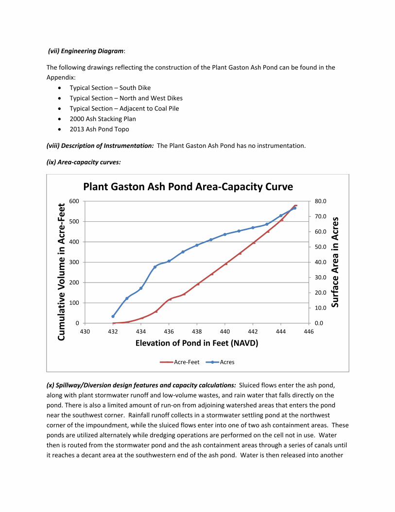
(ix) Area‐capacity curves:
(x) Spillway/Diversion design features and capacity calculations: Sluiced flows enter the ash pond,
along with plant stormwater runoff and low‐volume wastes, and rain water that falls directly on the
pond. There is also a limited amount of run‐on from adjoining watershed areas that enters the pond
near the southwest corner. Rainfall runoff collects in a stormwater settling pond at the northwest
corner of the impoundment, while the sluiced flows enter into one of two ash containment areas. These
ponds are utilized alternately while dredging operations are performed on the cell not in use. Water
then is routed from the stormwater pond and the ash containment areas through a series of canals until
it reaches a decant area at the southwestern end of the ash pond. Water is then released into another
0.0
10.0
20.0
30.0
40.0
50.0
60.0
70.0
80.0
0
100
200
300
400
500
600
430 432 434 436 438 440 442 444 446Surface Area in Acres
Cumulative Volume in
Acre‐Feet
Elevation of Pond in Feet (NAVD)
Plant Gaston Ash Pond Area‐Capacity Curve
Acre‐Feet Acres
long canal until it reaches the main outlet structure. The outlet structure consists of an approximately 8
foot riser with an invert elevation of approximately 409 ft. The riser connects to the 36‐in spillway pipe
that discharges from the ash pond.
The ash pond has present water capacity of about 22,036,000 cubic feet above the normal operating
level, based on the 2013 topographical survey. The design storm for the Plant Gaston Ash Pond is the
PMP. The rainwater volume during a PMP/24‐hour design rainfall event is 1,384 acre‐ft. The excess
water capacity remaining after a 100‐year/24‐hour event is 104 acre‐ft. The normal pool at the outlet is
approximately Elev. 432 ft. After a PMP/24‐hour event, water will overtop the embankment elevation
of 444 ft. At the overtopping elevation of EL 444 ft, the spillway is capable of discharging 173 cfs.
(xi) Provisions for surveillance, maintenance and repair: Inspections of dams and dikes are critical
components and are conducted on a regular basis—at least annually by professional dam safety
engineers and at a minimum interval of every seven days by qualified persons at the plant. In addition,
inspections are performed after unusual events such as storms. The inspections provide assurance that
structures are sound and that action is taken, as needed, based on the findings. Safety inspections
include numerous checklist items. Specific items vary from site to site but may include observations of
such things as pond levels, weather conditions, rainfall since the prior inspection, conditions of slopes
and drains, erosion, animal damage, ant hills, alignment of retaining structures and more. Dam safety
engineers inspect any maintenance or remediation performed since the previous inspection, check the
status of work recommended at prior inspections, ensure that the posting of emergency notification
information is up to date and evaluate any items noted during plant personnel inspections.
Construction specifications: Design cross‐sections are presented in the Appendix.
(xii) Known record of structural instability: There are no known instances of structural instability at the
CCR unit.

Appendix
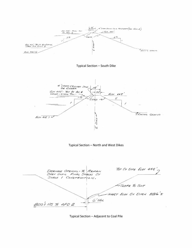
Typical Section – South Dike
Typical Section – North and West Dikes
Typical Section – Adjacent to Coal Pile
Alabama Power Company