hitachi new v17 8-02-59
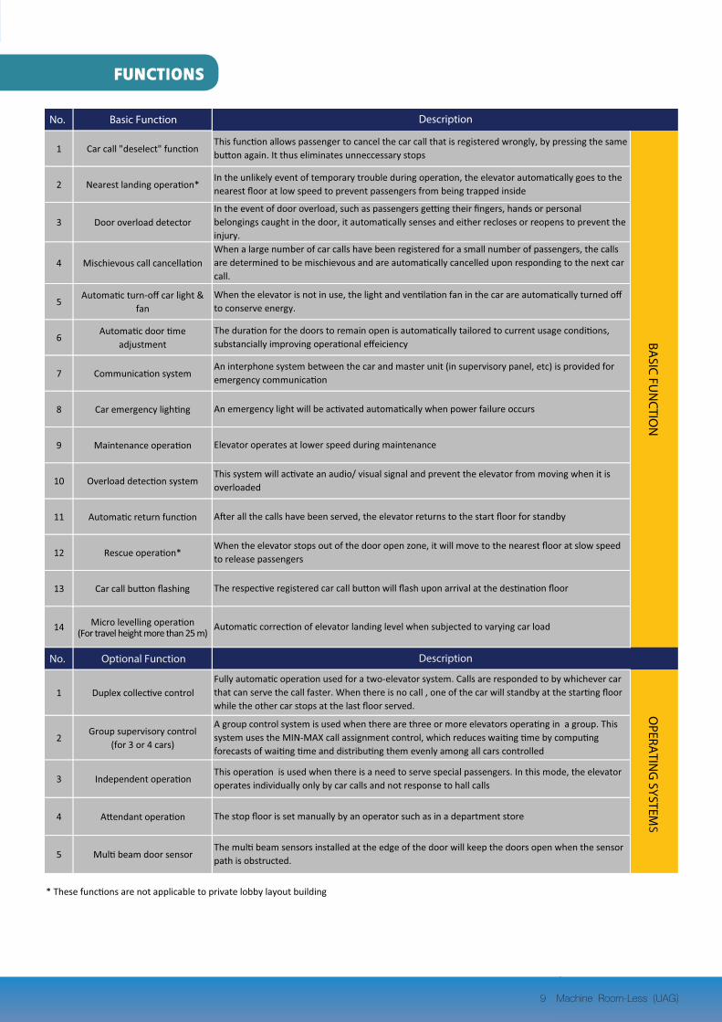
TRANSCRIPT


3 Machine Room-Less (UAG)
MACHINE ROOM-LESSELEVATOR
Space-saving ElevatorWith this Machine Room-less elevator, the space could be saved and utilized effectively, thus maximizing rentable space and reducing construction cost for the customer.
Energy-saving ElevatorThis model adopted a gear-less traction machine and the latest Insulated Gate Bipolar Transistor (IGBT) Technology to reduce the capacity of the motor and other electrical equipment, resulting in substantial savings in energy costs.
The overhead dimensions have been reduced by using under-slung mechanism
The slim control panel has been developed which can be installed within elevator hoistway
The slim type gear-less machine has been located at the side or the top of the elevator hoistway
CAGE
MAIN ROPE
ENTRANCE
GOVERNOR BUFFER
TRACTION MACHINE
CONTROL PANEL
COUNTERWEIGHT
GUIDE RAIL
SAFETY DEVICE

4 Machine Room-Less (UAG)
AS-1X (narrow) type JambJamb frame :Stainless Steel Hairline (SUS-H)Door panel :LPS with trimDoor sill :Extruded hard aluminumHall button with indicator : VIB-12BAuø35D
Ceiling : BS-11 Center : Milky white acrylicSurrounding : Stainless Steel Hairline (SUS-H)Lighting : LEDHeight (from floor) : 2300 mm. Front return/transom panel : Stainless Steel Hairline (SUS-H) Side and rear wall (3 sides) : Stainless Steel Hairline (SUS-H)Kick plate : Stainless Steel Hairline (SUS-H)Flooring : Vinyl tile Car door : LPS with trimDoor sill : Extruded hard aluminumVentilation : Air-blown through ceiling ductCar position indicator : Dot matrix, incorporated into car operating panelOperating panel : OPV-BAuD
For Passenger
STANDARD CAR AND CEILING DESIGN

5 Machine Room-Less (UAG)
AS-1X (narrow) type JambJamb frame :Stainless Steel Hairline (SUS-H)Door panel :LPS with trimDoor sill :Extruded hard aluminumHall button with indicator : VIB-12BAuø35D
Ceiling : BS-11Center : Milky white acrylicSurrounding : Stainless Steel Hairline (SUS-H)Lighting : LEDHeight (from floor) : 2300 mm. Front return/transom panel :Stainless Steel Hairline (SUS-H)Side and rear wall (3 sides) :Stainless Steel Hairline (SUS-H)Kick plate :Stainless Steel Hairline (SUS-H)Flooring :Vinyl tileCar door :LPS with trimDoor sill :Extruded hard aluminumHandrail :Flat type, Stainless steel hairlineVentilation :Air-blown through ceiling ductCar position indicator :Dot matrix, incorporated into car operating panelOperating panel : OPV-BAuD
For Bed

6 Machine Room-Less (UAG)
Operating panelOPV-BAuDOperating panel
Face plateStainless Steel Hairline (SUS-H)Button typeP14F-ULIndicator typeDot matrix
Hall buttons & Indicators
VIB-12BAuø35DHall button with indicator
Face plateStainless Steel Hairline (SUS-H)Button typeP14F-ULIndicator typeDot matrix
Hall button
BL-76Hall buttonFace plateStainlessSteel Hairline(SUS-H)
Hall Indicator
HF-119Hall indicatorFace plateStainless Steel Hairline (SUS-H)Indicator typeDot matrix
Hall lanterns
OPV-BYAuFace plateStainless Steel Hairline (SUS-H)Indicator TypeDot Matrix
BL-76Hall buttonFace plateStainless Steel Hairline (SUS-H)
L-03DXHall lantern with IndicatorFace plateStainless Steel Hairline (SUS-H)Indicator typeDot matrix
Operating panel, Indicator seriesSTANDARD
OPTION
Operating panel (For Handicapped)
L-03Hall lantern Face plateStainless Steel Hairline (SUS-H)

7 Machine Room-Less (UAG)
Entrance DesignsNo. Item Finishes/ Designs/ Types
1 Jamb Frame Narrow Type (AS-1X) Stainless Steel Hairline (SUS-H)
2 Sill Extruded Hard Aluminum
3 Door LPS with Trim
4 Hall Button and Indicator
IncorporatedType
Dot Matrix Indicatorand Plastic Resin Button
Operating panel (For Handicapped)
Car Designs
List of standard designs and finishes
No. Item Finishes/ Designs/ Types
1 Ceiling BS-11
2 Car Wall (3 sides) Stainless Steel Hairline (SUS-H)
3 Front Return Panel & Car Transom Panel Stainless Steel Hairline (SUS-H)
4 Car Door LPS with Trim
5 Kickplate (3 sides) Stainless Steel Hairline (SUS-H)
6 Sill Extruded Hard Aluminum
7 Operating Panel Stainless Steel Hairline with Dot Matrix Indicatorand Plastic Resin Button OPV-BAuD
(VIB-12BAuø35D)

8 Machine Room-Less (UAG)
Designs and Colors
Ceiling
GA 202 GA 201
SA 606
GA 203 GA 204
SA 613
GA 205 SA 605
SA 614
7170UNMetal Pearl Rosewood
5475SPBlondbrush Wood-Cross
0869NTPowdered Oak
2726NTNatural Beech
7171UNMetal Pearl Steel
8834NTSmoke Strand
5261NTSandy Sakura
7158UNCosmic Dusk
9401UNAluminium White
5262UNWhite Sakura
7157UNCosmic Dawn
6006UNCanadian Pine (Straight)
Designs for Car Doors / Entrance Doors
Floor (Vinyl Tiles)
STANDARD
PASSENGER TYPE BED TYPE
OPTION
DX-11
BS-11 BS-11
9 Machine Room-Less (UAG)
FUNCTIONSS

10 Machine Room-Less (UAG)
No. Optional Function
6 Hall lantern
7 Automatic bypass operation
8 Sub operating panel
9 Closed-circuit TV (CCTV)
10 Fire emergency operation
11Emergency operation for power
failure by building standby generator
12Automatic rescue device for
power failure*
13 Elevator supervisory panel
* These functions are not applicable to private lobby layout building
Hall lanterns can be provided instead of hall indicators. (For 3 or 4 cars group control, hall lantern will be provided as basic feature)
When the car is fully loaded , it will only respond to car calls and bypass all hall calls
Additional floor selection and door open/close buttons are located on the side opposite the main operating panel
In the event of buidling power failure, the elevator can be operated by building standby generator to move it to the designated floor
Description
In the event of power failure, the system automatically changes over to batterry power to bring the elevator to the nearest floor
Various supervisory operations, communication and status monitoring can be provided through either the conventional LED based type
For monitoring of movement inside the car by security personnel. (camera, recorder cabling by others)
In the event of fire, the elevator is automatically brought to the designated floor when it remains inoperative for passenger safety
FUNCTIONS
10 Machine Room-Less (UAG)
OTHER FU
NCTIO
NS

11 Machine Room-Less (UAG)
Dimensions of Hoistway & LocationBased on Japan Industrial Standard (JIS) regulation (non-fire rated door)
1
2
3
4
5
6
7
8
9
10
11
12
13
14
15
16
17
18
19
12 Machine Room-Less (UAG)
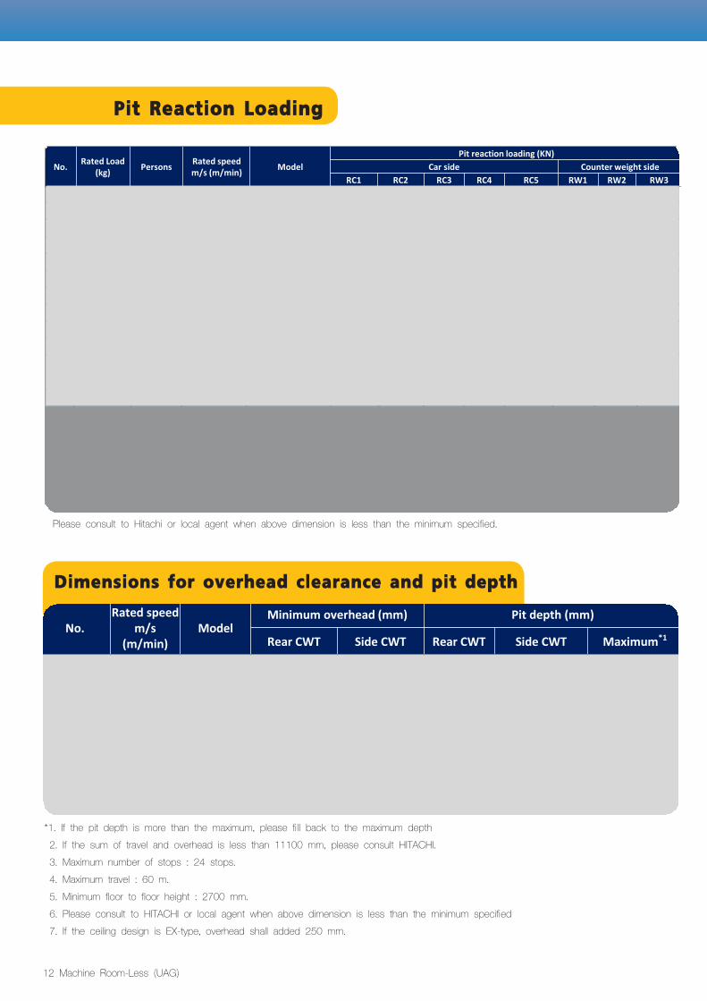
Please consult to Hitachi or local agent when above dimension is less than the minimum specified.
*1. If the pit depth is more than the maximum, please fill back to the maximum depth 2. If the sum of travel and overhead is less than 11100 mm, please consult HITACHI. 3. Maximum number of stops : 24 stops. 4. Maximum travel : 60 m. 5. Minimum floor to floor height : 2700 mm. 6. Please consult to HITACHI or local agent when above dimension is less than the minimum specified 7. If the ceiling design is EX-type, overhead shall added 250 mm.
Pit Reaction Loading
No.Rated speed
m/s (m/min)
ModelMinimum overhead (mm) Pit depth (mm)
Rear CWT Side CWT Rear CWT Side CWT Maximum*1
1 1.0 (60)
UAG
3600 3900 1400 1650
2 1.5 (90) 3850 4000 1400 1800
3 1.75 (105) 4000 4050 1450 1850
4 1.0 (60)
UAB
3600 1600 1800
5 1.5 (90) 3850 1600 1800
6 1.75 (105) 4000 1650 1850
Dimensions for overhead clearance and pit depth
11
RC1 RC2 RC3 RC4 RC5 RW1 RW2 RW3
1 450 6 1.0 (60) UAG-450-CO60 62 24 26 53 44 20
2 1.0 (60) UAG-600-CO60 73 25 29 61 48 20
3 1.5 (90) UAG-600-CO90
4 1.75 (105) UAG-600-CO105
5 1.0 (60) UAG-750-CO60 85 28 32 70 58 22
6 1.5 (90) UAG-750-CO90
7 1.75 (105) UAG-750-CO105
8 1.0 (60) UAG-900-CO60 96 31 35 78 60 24
9 1.5 (90) UAG-900-CO90
10 1.75 (105) UAG-900-CO105
11 1.0 (60) UAG-1000-CO60 102 32 36 81 62 24
12 1.5 (90) UAG-1000-CO90
13 1.75 (105) UAG-1000-CO105
14 1.0 (60) UAB-750-2S60 77 64
15 1.5 (90) UAB-750-2S90 93.5
16 1.75 (105) UAB-750-2S105 94
17 1.0 (60) UAB-1000-2S60 87.5 67
18 1.5 (90) UAB-1000-2S90 104.5
19 1.75 (105) UAB-1000-2S105 105
73 49.5 21.5
No.Rated Load
(kg)Persons
Rated speed m/s (m/min)
Model
Pit reaction loading (KN)
Car side Counter weight side
600 987 26.5 30.5
23.5
900 13115 32.5 36.5 94 61.5 25.5
750 11102 29.5 33.5 84
100082.5
63.5 25.5
75077
1000 15122 33.5 37.5 98
59.5
17
31 28.5
34 31
37 16.5
39
No. Rated Load (kg) Persons Rated speed
m/s (m/min) ModelPit reaction loading (KN)
Car side Counter weight sideRC1 RC2 RC3 RC4 RC5 RW1 RW2 RW3
1 450 6 1.0 (60) UAG-450-CO60 62 24 22 53 44 202
550 81.0 (60) UAG-550-CO60 67 24 24 56 47 19
3 1.5 (90) UAG-550-CO9080 25.5 24.5 68 48.5 20.5
4 1.75 (105) UAG-550-CO10525 25 61 48 205
600 91.0 (60) UAG-600-CO60 73
6 1.5 (90) UAG-600-CO9087 26.5 26.5 73 49.5 21.5
7 1.75 (105) UAG-600-CO1058
700 101.0 (60) UAG-700-CO60 82 28 27 68 56 22
9 1.5 (90) UAG-700-CO9098 29.5 28.5 81 57.5 23.5
10 1.75 (105) UAG-700-CO10511
750 111.0 (60) UAG-750-CO60 85 28 28 70 58 22
12 1.5 (90) UAG-750-CO90102 29.5 29.5 84 59.5 23.5
13 1.75 (105) UAG-750-CO10514
900 131.0 (60) UAG-900-CO60 96 31 30 78 60 24
15 1.5 (90) UAG-900-CO90115 32.5 31.5 94 61.5 25.5
16 1.75 (105) UAG-900-CO10517
1000 151.0 (60) UAG-1000-CO60 102 32 32 81 62 24
18 1.5 (90) UAG-1000-CO90122 33.5 33.5 98 63.5 25.5
19 1.75 (105) UAG-1000-CO10520
7501.0 (60) UAB-750-2S60 85 28 28 70 58 22
21 1.5 (90) UAB-750-2S90102 29.5 29.5 84 59.5 23.5
22 1.75 (105) UAB-750-2S10523
10001.0 (60) UAB-1000-2S60 102 32 32 81 62 24
24 1.5 (90) UAB-1000-2S90122 33.5 33.5 98 63.5 25.5
25 1.75 (105) UAB-1000-2S105

13 Machine Room-Less (UAG)
Bed TypePassenger Type
Hoistway layout
Pit reaction loading
Dimensions of Hoistway & LocationDimensions of Hoistway & Location

14 Machine Room-Less (UAG)
Electrical Information
Wiring Diagram Shows the work to be done by others
Pit lightings including wiring & piping to be provided by others (minimum 200 lux at floor level) Power socket outlet including wiring & piping in pit to be provided by others
(*1) Main and lighting supply shall lead into the hoistway at the lowest landing level
Work to be done by building contractors
The preparatory work for elevator installation outlined below should be undertaken by building contractors in accordance with Hitachi drawings and applicable national or local or relevant codes and regulations
1. Prepare hoistway with proper framing and enclosure, suitable pit of proper depth with drains and water –proofing if required.
2. Provide and/ or cut all necessary holes, chasing, and openings and making good after equipment installation
3. Supply and secure all supports, reinforced concrete slabs, etc, necessary for installation of the machinery, doors, buffers, etc.
4. Provide all grouting works for entrance jamb frames, sills, hall buttons, indicator, brackets, bolts, 5. Prepare and erect suitable scaffolding and protective measures for the work in progress machine beam, etc.
6. Furnish mains for three-phase electric power and single-phase for car lighting supply and lift pit lighting and power outlet to the hoistway, following the instructions of the elevator contractor on outlet position
7. Provide, free of charge, a suitable theft-proof storage area of materials and tools during erection work.
8. Supply electric power for lighting of work area, installation work, elevator testing and spray painting
9. Hoisting hook 2 tonnes loading at top of the hoistway
10. Hoistway ventilation to be provided to maintain the hoistway temperature at below 40 c
Item Contents
Main power supply (*1)
To install the facilities to ensure that power does not fluctuate outside the range of -10% to +5% of the normal voltage rating and to ensure that the unbalance factor of voltage does not exceed 5%
Lighting power supply (*1)
To provide lighting power supply for car lighting indicators and maintenance work
Interphone To provide pipes and wiring located outside hoistway. To provide 12 interphone wires of 0.9 mm2/ elevator
Ventilation The temperature in the hoistway should be maintained below 40°C by provision of mechanical ventilation
Pit inspection receptacle
AC 200 V 10A power outlet and pit lighting with switch for maintenance shall be provided below the entrance floor level

15 Machine Room-Less (UAG)