hitachi virtual storage platform - hitachi vantara · product version document organization getting...
TRANSCRIPT

Product Version
Document Organization
Getting Help
FASTFIND LINKS
Contents
MK-90RD7041-09
Hitachi Virtual Storage PlatformInstallation Planning Guide

Hitachi VSP Installation Planning Guide
ii
©2010-2013 Hitachi Ltd, All rights reserved.
No part of this publication may be reproduced or transmitted in any form or by any means, electronic or mechanical, including photocopying and recording, or stored in a database or retrieval system for any purpose without the express written permission of Hitachi, Ltd. (hereinafter referred to as “Hitachi“), and Hitachi Data Systems Corporation (hereinafter referred to as “Hitachi Data Systems“).
Hitachi and Hitachi Data Systems reserve the right to make changes to this document at any time without notice and assume no responsibility for its use. This document contains the most current information available at the time of publication. When new or revised information becomes available, this entire document will be updated and distributed to all registered users.
All of the features described in this document may not be currently available. Refer to the most recent product announcement or contact your local Hitachi Data Systems sales office for information about feature and product availability.
Notice: Hitachi Data Systems products and services can be ordered only under the terms and conditions of Hitachi Data Systems' applicable agreements. The use of Hitachi Data Systems products is governed by the terms of your agreements with Hitachi Data Systems.
Hitachi is a registered trademark of Hitachi, Ltd., in the United States and other countries. Hitachi Data Systems is a registered trademark and service mark of Hitachi in the United States and other countries.
ShadowImage and TrueCopy are registered trademarks of Hitachi Data Systems.
AIX, FICON, FlashCopy, IBM, MVS/ESA, MVS/XA, OS/390, S/390, VM/ESA, VSE/ESA, z/OS, zSeries, z/VM, and zVSE are registered trademarks or trademarks of International Business Machines Corporation.
All other trademarks, service marks, and company names are properties of their respective owners.
Microsoft product screen shots reprinted with permission from Microsoft Corporation.

Contents iiiHitachi VSP Installation Planning Guide
Contents
Preface . . . . . . . . . . . . . . . . . . . . . . . . . . . . . . . . . . . . . . . . . . . . vSafety and environmental information . . . . . . . . . . . . . . . . . . . . . . . . . . . . . . . viIntended Audience . . . . . . . . . . . . . . . . . . . . . . . . . . . . . . . . . . . . . . . . . . . . viProduct Version . . . . . . . . . . . . . . . . . . . . . . . . . . . . . . . . . . . . . . . . . . . . . . . viDocument Revision Level . . . . . . . . . . . . . . . . . . . . . . . . . . . . . . . . . . . . . . . . viChanges in this Revision. . . . . . . . . . . . . . . . . . . . . . . . . . . . . . . . . . . . . . . . . viReferenced Documents . . . . . . . . . . . . . . . . . . . . . . . . . . . . . . . . . . . . . . . . . viDocument Organization . . . . . . . . . . . . . . . . . . . . . . . . . . . . . . . . . . . . . . . . . viiDocument Conventions . . . . . . . . . . . . . . . . . . . . . . . . . . . . . . . . . . . . . . . . . viiConvention for storage capacity values . . . . . . . . . . . . . . . . . . . . . . . . . . . . . .viiiAccessing product documentation . . . . . . . . . . . . . . . . . . . . . . . . . . . . . . . . . . ixGetting help . . . . . . . . . . . . . . . . . . . . . . . . . . . . . . . . . . . . . . . . . . . . . . . . . ixComments . . . . . . . . . . . . . . . . . . . . . . . . . . . . . . . . . . . . . . . . . . . . . . . . . . ix
1 Planning an installation. . . . . . . . . . . . . . . . . . . . . . . . . . . . . . . . 1-1Responsibilities . . . . . . . . . . . . . . . . . . . . . . . . . . . . . . . . . . . . . . . . . . . . . . 1-2
User responsibilities . . . . . . . . . . . . . . . . . . . . . . . . . . . . . . . . . . . . . . . . 1-2Hitachi Data Systems responsibilities . . . . . . . . . . . . . . . . . . . . . . . . . . . . 1-2
Installation planning checklist . . . . . . . . . . . . . . . . . . . . . . . . . . . . . . . . . . . . 1-2
2 Safety requirements . . . . . . . . . . . . . . . . . . . . . . . . . . . . . . . . . . 2-1General safety guidelines . . . . . . . . . . . . . . . . . . . . . . . . . . . . . . . . . . . . . . . 2-2Work safety guidelines . . . . . . . . . . . . . . . . . . . . . . . . . . . . . . . . . . . . . . . . . 2-2
Warning about moving parts. . . . . . . . . . . . . . . . . . . . . . . . . . . . . . . . . . 2-3Electrical safety guidelines . . . . . . . . . . . . . . . . . . . . . . . . . . . . . . . . . 2-3
3 Installation requirements . . . . . . . . . . . . . . . . . . . . . . . . . . . . . . 3-1Safety requirements. . . . . . . . . . . . . . . . . . . . . . . . . . . . . . . . . . . . . . . . . . . 3-2General site requirements . . . . . . . . . . . . . . . . . . . . . . . . . . . . . . . . . . . . . . 3-2
Equipment clearances . . . . . . . . . . . . . . . . . . . . . . . . . . . . . . . . . . . . . . 3-2
Hitachi VSP Installation Planning Guide
iv Contents
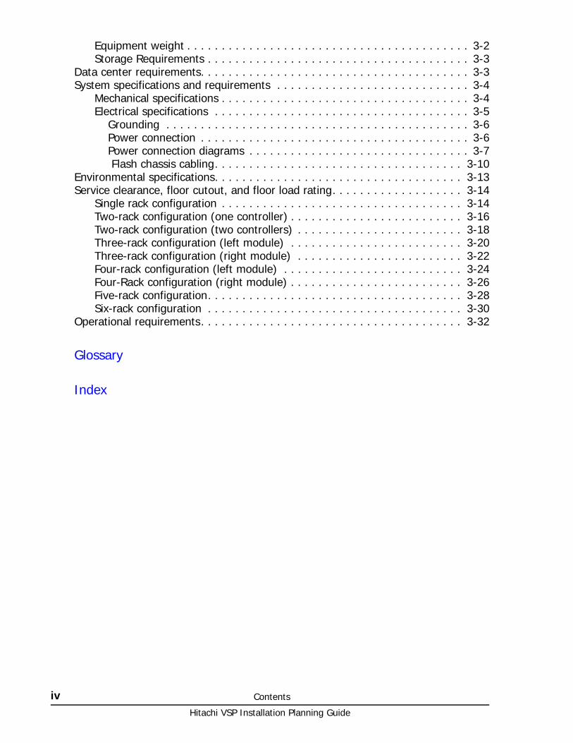
Equipment weight . . . . . . . . . . . . . . . . . . . . . . . . . . . . . . . . . . . . . . . . . 3-2Storage Requirements . . . . . . . . . . . . . . . . . . . . . . . . . . . . . . . . . . . . . . 3-3
Data center requirements. . . . . . . . . . . . . . . . . . . . . . . . . . . . . . . . . . . . . . . 3-3System specifications and requirements . . . . . . . . . . . . . . . . . . . . . . . . . . . . 3-4
Mechanical specifications . . . . . . . . . . . . . . . . . . . . . . . . . . . . . . . . . . . . 3-4Electrical specifications . . . . . . . . . . . . . . . . . . . . . . . . . . . . . . . . . . . . . 3-5
Grounding . . . . . . . . . . . . . . . . . . . . . . . . . . . . . . . . . . . . . . . . . . . . 3-6Power connection . . . . . . . . . . . . . . . . . . . . . . . . . . . . . . . . . . . . . . . 3-6Power connection diagrams . . . . . . . . . . . . . . . . . . . . . . . . . . . . . . . . 3-7 Flash chassis cabling. . . . . . . . . . . . . . . . . . . . . . . . . . . . . . . . . . . . 3-10
Environmental specifications. . . . . . . . . . . . . . . . . . . . . . . . . . . . . . . . . . . . 3-13Service clearance, floor cutout, and floor load rating. . . . . . . . . . . . . . . . . . . 3-14
Single rack configuration . . . . . . . . . . . . . . . . . . . . . . . . . . . . . . . . . . . 3-14Two-rack configuration (one controller) . . . . . . . . . . . . . . . . . . . . . . . . . 3-16Two-rack configuration (two controllers) . . . . . . . . . . . . . . . . . . . . . . . . 3-18Three-rack configuration (left module) . . . . . . . . . . . . . . . . . . . . . . . . . 3-20Three-rack configuration (right module) . . . . . . . . . . . . . . . . . . . . . . . . 3-22Four-rack configuration (left module) . . . . . . . . . . . . . . . . . . . . . . . . . . 3-24Four-Rack configuration (right module) . . . . . . . . . . . . . . . . . . . . . . . . . 3-26Five-rack configuration. . . . . . . . . . . . . . . . . . . . . . . . . . . . . . . . . . . . . 3-28Six-rack configuration . . . . . . . . . . . . . . . . . . . . . . . . . . . . . . . . . . . . . 3-30
Operational requirements. . . . . . . . . . . . . . . . . . . . . . . . . . . . . . . . . . . . . . 3-32
Glossary
Index

Preface vHitachi VSP Installation Planning Guide
Preface
This manual provides specifications and requirements needed to plan the installation and prepare the site where the Hitachi Virtual Storage Platform storage system will be installed.
Read this document carefully to understand how to use this product, and maintain a copy for reference.
This preface includes the following information:
□ Safety and environmental information
□ Intended Audience
□ Product Version
□ Document Revision Level
□ Changes in this Revision
□ Referenced Documents
□ Document Organization
□ Document Conventions
□ Convention for storage capacity values
□ Accessing product documentation
□ Getting help
□ Comments

Hitachi VSP Installation Planning Guide
vi Preface
Safety and environmental information
Intended AudienceThis document is intended for system administrators, Hitachi Data Systems representatives, and authorized service providers who are involved in installing, configuring, and operating the Hitachi Virtual Storage Platform storage system.
Readers of this document should have at least the following knowledge and experience:
• You should have a background in data processing and understand RAID storage systems and their basic functions.
• You should be familiar with the Hitachi Virtual Storage Platform storage system, and have read the Hitachi Virtual Storage Platform User and Reference Guide.
Product VersionThis document revision applies to Hitachi Virtual Storage Platform firmware version 70-06-0x and higher.
Document Revision Level
Changes in this Revision• Updated the Environmental Specifications.
Referenced DocumentsHitachi Virtual Storage Platform documentation:
Caution: Before operating or working on the Virtual Storage Platform storage system, read the safety and environmental information in Safety requirements on page 2-1.
Revision Date Description
MK-90RD7041-00 August 2010 Initial release
MK-90RD7041-01 November 2010 Supersedes and replaces MK-90RD7041-00
MK-90RD7041-02 May 2011 Supersedes and replaces MK-90RD7041-01
MK-90RD7041-03 August 2011 Supersedes and replaces MK-90RD7041-02
MK-90RD7041-04 November 2011 Supersedes and replaces MK-90RD7041-03
MK-90RD7041-05 March 2012 Supersedes and replaces MK-90RD7041-04
MK-90RD7041-06 June 2012 Supersedes and replaces MK-90RD7041-05
MK-90RD7041-07 November 2012 Supersedes and replaces MK-90RD7041-06
MK-90RD7041-08 November 2012 Supersedes and replaces MK-90RD7041-07
MK-90RD7041-09 July 2013 Supersedes and replaces MK-90RD7041-08
Preface viiHitachi VSP Installation Planning Guide
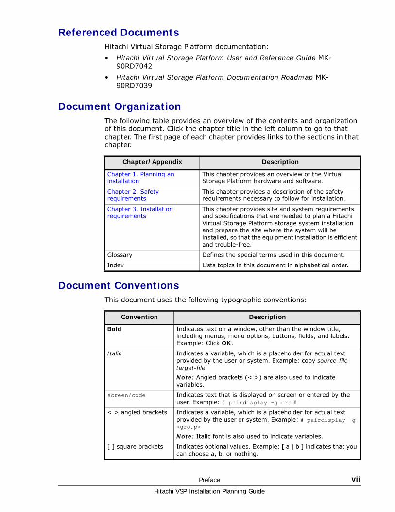
Referenced DocumentsHitachi Virtual Storage Platform documentation:
• Hitachi Virtual Storage Platform User and Reference Guide MK-90RD7042
• Hitachi Virtual Storage Platform Documentation Roadmap MK-90RD7039
Document OrganizationThe following table provides an overview of the contents and organization of this document. Click the chapter title in the left column to go to that chapter. The first page of each chapter provides links to the sections in that chapter.
Document ConventionsThis document uses the following typographic conventions:
Chapter/Appendix Description
Chapter 1, Planning an installation
This chapter provides an overview of the Virtual Storage Platform hardware and software.
Chapter 2, Safety requirements
This chapter provides a description of the safety requirements necessary to follow for installation.
Chapter 3, Installation requirements
This chapter provides site and system requirements and specifications that ere needed to plan a Hitachi Virtual Storage Platform storage system installation and prepare the site where the system will be installed, so that the equipment installation is efficient and trouble-free.
Glossary Defines the special terms used in this document.
Index Lists topics in this document in alphabetical order.
Convention Description
Bold Indicates text on a window, other than the window title, including menus, menu options, buttons, fields, and labels. Example: Click OK.
Italic Indicates a variable, which is a placeholder for actual text provided by the user or system. Example: copy source-file target-file
Note: Angled brackets (< >) are also used to indicate variables.
screen/code Indicates text that is displayed on screen or entered by the user. Example: # pairdisplay -g oradb
< > angled brackets Indicates a variable, which is a placeholder for actual text provided by the user or system. Example: # pairdisplay -g <group>
Note: Italic font is also used to indicate variables.
[ ] square brackets Indicates optional values. Example: [ a | b ] indicates that you can choose a, b, or nothing.

Hitachi VSP Installation Planning Guide
viii Preface
This document uses the following icons to draw attention to information:
Convention for storage capacity valuesPhysical and logical storage capacities of disk drives in Hitachi Data Systems’ storage products are calculated based on the following values:
Logical storage capacity values (logical device capacity) are calculated based on the following values:
| vertical bar Indicates that you have a choice between two or more options or arguments. Examples:
[ a | b ] indicates that you can choose a, b, or nothing.
{ a | b } indicates that you must choose either a or b.
Convention Description
Icon Meaning Description
Tip Tips provide helpful information, guidelines, or suggestions for performing tasks more effectively.
Note Notes emphasize or supplement important points of the main text.
Caution Cautions indicate that failure to take a specified action could result in damage to the software or hardware.
WARNING Warnings indicate that failure to take a specified action could result in loss of data or serious damage to hardware.
ELECTRIC SHOCK HAZARD
Failure to take appropriate precautions such as not opening or touching hazardous areas of the equipment could result in injury or death.
Logical Units : Block Size - 512 Bytes (Logical Disk Capacity)
1 KB (kilobyte) = 1,024 bytes (210) 1 TB (terabyte) = 1,0244 bytes
1 MB (megabyte) = 1,0242 bytes 1 PB (petabyte) = 1,0245 bytes
1 GB (gigabyte) = 1,0243 bytes 1 EB (exabyte) = 1,0246 bytes
Hard Disk Drives (HDDs) (Physical Disk Capacity)
1 KB = 1,000 bytes 1 TB = 1,0004 bytes
1 MB = 1,0002 bytes 1 PB = 1,0005 bytes
1 GB = 1,0003 bytes 1 EB = 1,0006 bytes
Preface ixHitachi VSP Installation Planning Guide
Accessing product documentationThe VSP user documentation is available on the Hitachi Data Systems Support Portal: https://Portal.HDS.com. Check this site for the most current documentation, including important updates that may have been made after the release of the product.
Getting helpThe Hitachi Data Systems customer support staff is available 24 hours a day, seven days a week. If you need technical support, log on to the Hitachi Data Systems support portal for contact information: https://Portal.HDS.com
CommentsPlease send us your comments on this document: [email protected]. Include the document title, number, and revision. Please refer to specific sections and paragraphs whenever possible.
Thank you! (All comments become the property of Hitachi Data Systems.)

Hitachi VSP Installation Planning Guide
x Preface

1
Planning an installation 1–1Hitachi VSP Installation Planning Guide
Planning an installation
This chapter describes the requirements and procedures to create a plan to install a Hitachi Virtual Storage Platform storage system.
□ Responsibilities
□ Installation planning checklist

Hitachi VSP Installation Planning Guide
1–2 Planning an installation
ResponsibilitiesThe responsibilities for installation planning are shared by the system users and Hitachi Data Systems support. The required installation planning tasks must be scheduled and completed to ensure successful and efficient installation of the Hitachi Virtual Storage Platform storage system.
User responsibilitiesYou are responsible for performing the following tasks to prepare for installation of the VSP storage system.
• Understand the applicable safety requirements associated with installing a VSP storage system.
• Understand the installation requirements for the VSP storage system. You can use the information in this manual to determine the specific requirements for your installation. As needed, review the Hitachi Virtual Storage Platform User and Reference Guide to familiarize yourself with the components, features, and functions of the VSP storage system.
• Verify that the installation site meets all installation requirements. A checklist is included in this section to help you with this task.
• Provide electrical hardware, including cables, connectors and receptacles that are required to connect the VSP storage system to site power.
• As needed, work with Hitachi Data Systems support to create an installation plan. Allow enough time to complete any changes to the plan, so your site is ready when the equipment arrives.
Hitachi Data Systems responsibilitiesHitachi Data Systems support is responsible for completing the following tasks:
• Assist you as needed during the installation planning process for your specific site and operational configuration
• Coordinate Hitachi Data Systems resources to ensure a successful installation and configuration of the Virtual Storage Platform storage system.
Installation planning checklistThe following checklist can help you ensure that your site meets all requirements to install a Virtual Storage Platform storage system. You can make copies of this checklist for each installation you perform and check each step after it has been performed. Completing this checklist can help ensure smooth and efficient installation of a VSP storage system.
Definition of terms
Note: The VSP storage system must be installed by trained Hitachi Data Systems personnel or trained authorized service providers. The VSP storage system is not a customer-installable product.

Planning an installation 1–3Hitachi VSP Installation Planning Guide
Equipment: The hardware delivered to the customer site that includes the VSP storage system components and racks.
Location: The specific location in the data center (area or “footprint” on the floor) where the VSP storage system will be installed.
User Information
Company .
Address .
Contact .
Phone .
Mobile .
Email .
Contact .
Phone .
Mobile .
Email .
Hitachi Data Systems Information
Contact .
Phone .
Mobile .
Email .
Contact .
Phone .
Mobile .
Email .
Notes .
. .
Installation Planning Checklist Yes No
Safety Requirements
See Data center requirements on page 3-3.
. .
Does the data center provide appropriate fire protection for computer equipment such as VSP storage systems?
. .
Is the data center free of hazards such as cables that obstruct access?
. .
Delivery Requirements
See Table 3-1 VSP shipping crate dimensions on page 3-2,
Table 3-2 VSP single rack dimensions on page 3-2, and
Table 3-3 Weight of typical VSP system configurations on page 3-3.
. .
Is the receiving area adequate for equipment delivery, unloading and unpacking? .
. .
Hitachi VSP Installation Planning Guide
1–4 Planning an installation
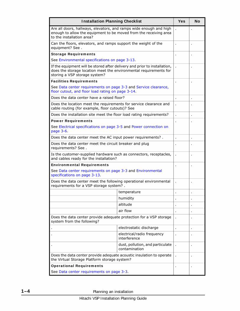
Are all doors, hallways, elevators, and ramps wide enough and high enough to allow the equipment to be moved from the receiving area to the installation area?
. .
Can the floors, elevators, and ramps support the weight of the equipment? See .
. .
Storage Requirements
See Environmental specifications on page 3-13.
. .
If the equipment will be stored after delivery and prior to installation, does the storage location meet the environmental requirements for storing a VSP storage system?
. .
Facilities Requirements
See Data center requirements on page 3-3 and Service clearance, floor cutout, and floor load rating on page 3-14.
. .
Does the data center have a raised floor? . .
Does the location meet the requirements for service clearance and cable routing (for example, floor cutouts)? See
. .
Does the installation site meet the floor load rating requirements? . .
Power Requirements
See Electrical specifications on page 3-5 and Power connection on page 3-6.
. .
Does the data center meet the AC input power requirements? . . .
Does the data center meet the circuit breaker and plug requirements? See .
. .
Is the customer-supplied hardware such as connectors, receptacles, and cables ready for the installation?
. .
Environmental Requirements
See Data center requirements on page 3-3 and Environmental specifications on page 3-13.
. .
Does the data center meet the following operational environmental requirements for a VSP storage system? .
. .
temperature . .
humidity . .
altitude . .
air flow . .
Does the data center provide adequate protection for a VSP storage system from the following?
. .
. electrostatic discharge . .
. electrical/radio frequency interference
. .
. dust, pollution, and particulate contamination
. .
Does the data center provide adequate acoustic insulation to operate the Virtual Storage Platform storage system?
. .
Operational Requirements
See Data center requirements on page 3-3.
. .
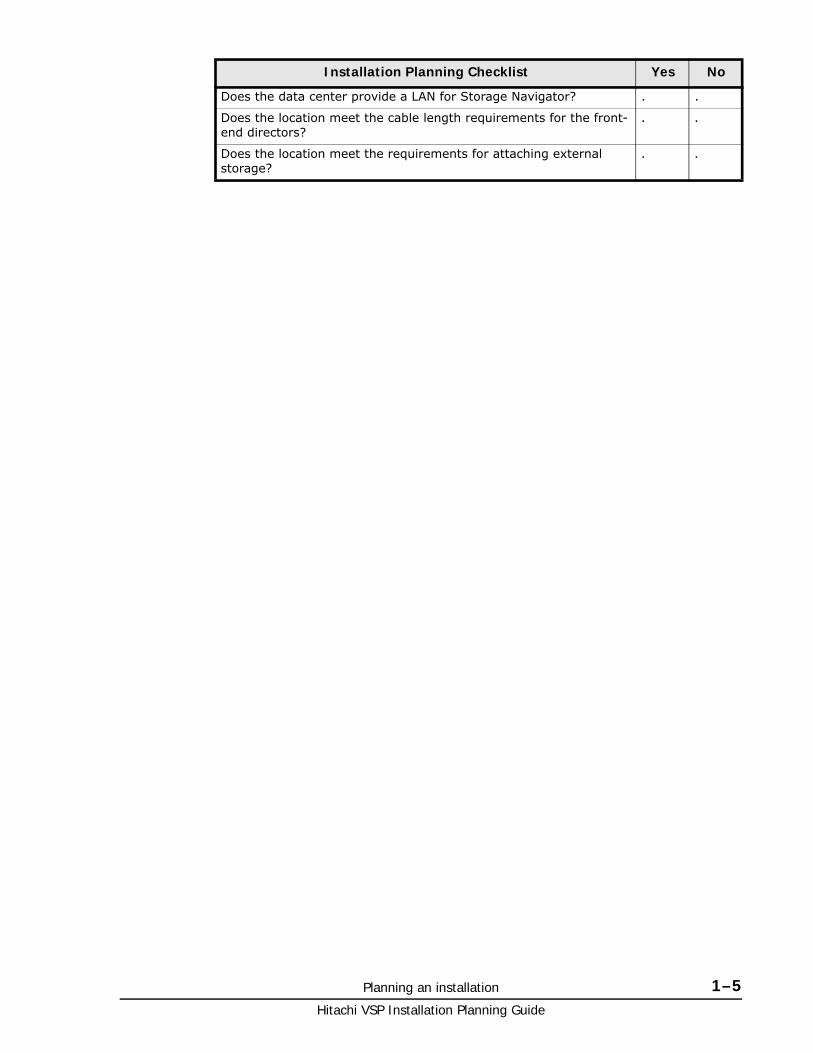
Installation Planning Checklist Yes No
Planning an installation 1–5Hitachi VSP Installation Planning Guide
Does the data center provide a LAN for Storage Navigator? . .
Does the location meet the cable length requirements for the front-end directors?
. .
Does the location meet the requirements for attaching external storage?
. .
Installation Planning Checklist Yes No

Hitachi VSP Installation Planning Guide
1–6 Planning an installation

2
Safety requirements 2–1Hitachi VSP Installation Planning Guide
Safety requirements
Install Hitachi equipment in accordance with the local safety codes and regulations that apply to the facility. This chapter contains additional safety information that may apply to your facility. Read and follow the safety guidelines in this chapter before installing the equipment. The key sections in this chapter are:
□ General safety guidelines
□ Work safety guidelines

Hitachi VSP Installation Planning Guide
2–2 Safety requirements
General safety guidelinesObserve the following general site guidelines:
• General Requirements: The data center must comply with all applicable safety regulations, standards, and requirements for installing and operating industrial computer equipment similar to a Virtual Storage Platform storage system.
• Fire protection: The data center must have an operational fire protection system appropriate for use with computer and electrical equipment.
• Hazards: The data center must be free of hazards (for example, cables on the floor that block access or that can cause people to trip).
• Equipment modifications: Do not make mechanical or electrical modifications to the equipment. Hitachi Data Systems is not responsible for regulatory compliance of a modified Hitachi Data Systems product.
• Earthquake Safety: To minimize personal injury in the event of an earthquake, securely fasten the control and drive chassis to a rigid structure extending from the floor to the ceiling or from the walls of the room in which the system is located.
• Cabling: Do not block walkways when routing cables. Do not place heavy materials on cables. Do not place cables near any possible source of heat.
• Warning and safety labels: Safety warnings, cautions, and instructions in various languages are attached to the VSP storage system components. The safety warnings provide guidelines to follow when working with any equipment. Before working on the storage system, read all safety and warning labels attached to it. If the labels become dirty, damaged, unreadable, or peel off, contact the Hitachi Data Systems support center.
• Authorized personnel: Allow only qualified and authorized personnel (for example, a licensed electrician) to perform hazardous tasks.
Work safety guidelinesObserve the following site guidelines:
• Do not wear loose clothing that could get caught in the equipment or mounting hardware. Fasten your tie or scarf and roll up your sleeves.
• Wear safety glasses when working under conditions that are hazardous to your eyes.
• Do not perform any action that creates a potential hazard to people or makes the equipment or rack unsafe.
• Keep walkways clear of tools, power cables, and parts to prevent them from being stepped on or causing people to trip and fall over them.
• Do not work on the equipment or disconnect cables during a thunderstorm, when wearing a wool sweater or other heavy wool clothing, or when power is applied.
• Keep floors dry to prevent slips and falls.
Safety requirements 2–3Hitachi VSP Installation Planning Guide
• Do not use ungrounded power cables.
• Keep the area clear and dust-free during and after installation.
• Do not block or cover equipment openings. Ensure that all equipment has adequate airflow. Failure to follow these guidelines can cause overheating and affect the system reliability.
• The rack is equipped with casters so that you can move it short distances to position it for final installation. Use enough personnel when moving a rack, especially on sloping loading docks and ramps to a raised computer room floor. Move the cabinet slowly and deliberately, and make sure that the floor is free from foreign objects and cables that the cabinet could roll over.
Warning about moving partsEven though customers do not install or maintain equipment, these guidelines are provided to prevent possible injury when working with authorized service personnel. Observe the following warning related to moving parts:
• Tuck in any loose clothing so that it cannot be caught by a moving or rotating part such as a fan.
• Tie up long hair.
• Unless otherwise specifically instructed, do not supply power to any device that contains rotating or moving parts that are not properly covered.
Electrical safety guidelines
Even though customers do not install or maintain equipment, these guidelines are provided to prevent possible injury when working with authorized service personnel in the area where equipment is installed. Observe the following electrical safety guidelines:
• Disconnect all power before installation, deinstallation, or moving equipment.
• Ensure that the voltage and frequency of your power source match the voltage and frequency required by the system.
• All equipment should be properly grounded for proper operation and safety. To reduce the risk of electric shock or damage to equipment, follow proper grounding procedures.
WARNING: To avoid injury, wear protective footwear when moving equipment.

Hitachi VSP Installation Planning Guide
2–4 Safety requirements

3
Installation requirements 3–1Hitachi VSP Installation Planning Guide
Installation requirements
This chapter provides site and system requirements and specifications that are needed to plan a Hitachi Virtual Storage Platform storage system installation and prepare the site where the system will be installed, so that the equipment installation is efficient and trouble-free.
This chapter may not provide all the information needed for every installation. The installation and maintenance documents used by Hitachi Data Systems personnel contain complete information, including specifications for all possible installations. Contact Hitachi Data Systems support if you need information that is not included in this chapter.
□ Safety requirements
□ General site requirements
□ Data center requirements
□ System specifications and requirements
□ Environmental specifications
□ Service clearance, floor cutout, and floor load rating
□ Operational requirements

Hitachi VSP Installation Planning Guide
3–2 Installation requirements
Safety requirements
General site requirementsThe customer site must accommodate the delivery and movement of the equipment from the receiving dock to the installation location in the data center.
Equipment clearancesReceiving area: The receiving dock, storage area, and receiving area must be large enough to allow movement of and access to crated or packed equipment. The dimensions of a shipping crate for a single rack are shown in the following table.
Table 3-1 VSP shipping crate dimensions
Other areas: The hallways, doorways, ramps, and elevators must be large enough to allow a single unpacked rack to be moved to the installation location. Unless the distance between the receiving dock and the data center is very long, Virtual Storage Platform storage systems are typically unpacked in the receiving area and the individual racks with pre-installed equipment are rolled on their casters to the data center. The following table provides the dimensions of the VSP storage system.
Table 3-2 VSP single rack dimensions
Equipment weightThe floors, elevators, and ramps must be able to support the weight of the delivered equipment as it is moved to the installation location. Spreader plates may be required to distribute the load and protect the floor as the equipment is moved from the receiving area to the installation location. Consult the system bill of materials to establish the anticipated summary weights.
Caution: Before operating or working on the Virtual Storage Platform , read the safety and environmental information in Safety requirements on page 2-1.
Item Height Width Depth
Shipping crate, single rack
84 in. / 2134 mm 42 in. / 1067 mm 55 in. / 1397 mm
Item Height Width Depth
Single rack 73.1 in. / 2005 mm 24.0 in. / 610 mm 43.3 in. /1100 mm

Installation requirements 3–3Hitachi VSP Installation Planning Guide
The weight of the equipment depends on the storage system configuration. The weight for a fully configured storage system can reach 9784 pounds / 4413 kilograms). The following table provides weights of typical system configurations.
Table 3-3 Weight of typical VSP system configurations
Storage RequirementsIf the equipment must be stored after delivery and prior to installation, the storage location must meet the storage environmental requirements for the VSP storage system. See Environmental specifications on page 3-13 in this chapter for environmental storage requirements.
Data center requirementsThe data center must meet the following facilities requirements:
Table 3-4 Data center requirements
Note: The data in the following table was taken from measurements of a system in a controlled environment. To calculate the weight of a specific system, use the Power and Weight Calculator at
http://www.hds.com/go/weight-and-power-calculator/
Contact technical support if you need assistance using this tool.
Dimension Single Rack Single Module(3 racks)
Dual Module(6 racks)
System
Weight
Min (lbs / kg) 767 / 346 (Diskless) 3610 / 1628 7503 / 3384
Max (lbs / kg) 862 / 389 4592 / 2071 9784 / 4413
Rack Weight
(lbs / kg) 292.6 / 133 Rack Weight is included in system weight
Item Description
General The data center must provide appropriate power, air conditioning, cabling, and fire protection.
ESD The data center must provide adequate protection from electrostatic discharge (ESD).
Electrical interference
The data center must provide adequate protection from electrical/radio frequency interference.
Contamination The data center must provide adequate protection from dust, pollution, and particulate contamination.
Acoustics The data center must provide adequate acoustic insulation for operating the system.
User-supplied hardware
This includes cables, connectors, and receptacles that must be available and ready when the system is installed.
Hitachi VSP Installation Planning Guide
3–4 Installation requirements
System specifications and requirementsThis section describes the physical characteristics of a VSP storage system, including
• Mechanical specifications on page 3-4
• Electrical specifications on page 3-5
• Environmental specifications on page 3-13
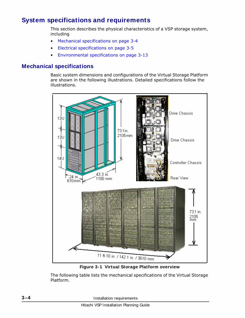
Mechanical specificationsBasic system dimensions and configurations of the Virtual Storage Platform are shown in the following illustrations. Detailed specifications follow the illustrations.
The following table lists the mechanical specifications of the Virtual Storage Platform.
Figure 3-1 Virtual Storage Platform overview

Installation requirements 3–5Hitachi VSP Installation Planning Guide
Table 3-5 VSP mechanical specifications
Electrical specifications
The following table lists the electric power requirements and approximate power consumption of a typical VSP storage system. Detailed electrical specifications are located in the Hitachi Virtual Storage Platform User and Reference Guide.
Table 3-6 VSP electric power requirements
Table 3-7 Power consumption, single phase current
Dimension One Rack Two Racks
Three Racks
Four Racks
Five Racks
Six Racks
Width
in. / mm
24.0 /
610
47.3 / 1201
71.3 / 1811
94.7 / 2405
118.8 / 3018
142.1 / 3610
Depth
in. / mm
43.3 /1100
43.3 /1100
43.3 / 1100
43.3 /1100
43.3 /1100
43.3 / 1100
Height
in. / mm
73.1 / 2005
73.1 / 2005
73.1 / 2005
73.1 / 2005
73.1 / 2005
73.1 / 2005
Note: The current and power specifications in the following tables were measured on a VSP system in a controlled environment. To calculate the power and current draw of a specific system, use the Power and Weight calculator at
http://www.hds.com/go/weight-and-power-calculator/
Contact technical support if you need assistance using this tool.
Phase Voltage Frequency Power,Operating
Power,Standby
AC, single phase
2 wire + ground
200 V -8% min 240 V +6% max
50 ±3 Hz
60 ±2 Hz
41.4 KVA, maximum
23.02 KVA, maximum
AC, three phase delta
See Table 3-8 PDU plugs, circuit breakers, and receptacles1 on page 3-7 for connections.
208 V
+5/-15%
50/60 Hz 41.4 KVA, maximum
23.02 KVA, maximum
Configuration
Idle Max Power Consumption2
Current per rack (KW)7, 8
Current per rack (KW)7, 8
R00 (module 0 controller) 17.3 19.6

Hitachi VSP Installation Planning Guide
3–6 Installation requirements
Grounding
The site and site equipment must meet all of the following three grounding requirements.
• An insulated grounding conductor that is identical in size and insulation material and thickness to the grounded and ungrounded branch-circuit supply conductors. It must be green, with or without yellow stripes, and must be installed as a part of the branch circuit that supplies the unit or system.
• The grounding conductor described above should be connected to earth ground at the service equipment or other acceptable building earth ground. In the case of a high rise steel-frame structure, this can be the steel frame
• The attachment-plug receptacles in the vicinity of the unit or system must include a ground connection. The grounding conductors serving these receptacles must be connected to earth ground at the service equipment or other acceptable building earth ground.
Power connection
The AC power input for the VSP storage system has a duplex PDU structure that enables the equipment installed in the entire rack to remain powered on if power is removed from one of the two power distribution panels.
R10 (module 1 controller) 18.2 17.9
R01 (module 0 drive 1) 14.8 18.3
R11 (module 1 drive 1) 16.1 19.6
R02 (module 0 drive 2) 17.2 17.1
R12 (module 1 drive 2) 14.4 18.6
Total Power 98 111.1
Notes:
1. Data taken from measurements on a VSP storage system in a controlled environment.
2. Idle condition - system is powered on but not being accessed
3. Max power consumption - all disks are in write mode.
4. R00 and R01 are controller racks with one controller chassis and two drive chassis.
5. R01, R02, R11, and R12 are drive racks with three drive chassis each.
6. Total 2048 146 GB SAS drives.
7. power Factor 0.96
8. Voltage 210Vac
Configuration
Idle Max Power Consumption2
Current per rack (KW)7, 8
Current per rack (KW)7, 8
Note: Site power can be connected to the PDUs at either the top or bottom of the racks.

Installation requirements 3–7Hitachi VSP Installation Planning Guide
PDU plugs, circuit breakers, and receptacles
The PDU plugs must be appropriate for the power sources at the installation sites. Table 3-8 PDU plugs, circuit breakers, and receptacles1 on page 3-7 lists the plugs on the end of the PDU power cords. The power distribution panel at the installation site must have connectors that match these plugs.
Table 3-8 PDU plugs, circuit breakers, and receptacles1
Power connection diagrams
The following illustrations show the correct way to connect the PDUs to the PDPs. When connected as shown, either of the AC inputs can fail and the system will still operate normally.
Note: Depending on the configuration, the VSP storage system may draw considerably less power than the rating of the PDU plugs. Use the weight and power calculator to determine the power draw for a specific system. See the note on pageElectrical specifications on page 3-5.
Phase Location PDU Plug
Max Voltage Rating
Max Current Rating
No. of CB per PDU
Breaker
Rating
Power Supply Receptacle IEC
C14 2
Single Americas (except Brazil)
NEMA L6 30P twistlock
2 pole, 3 wire
A + B + gnd
208 V 30 A
per PDU
2 16 A,
20 A trip
2 pole, 3 wire
220 VAC
A + B + gnd
EMEA / APAC/
Brazil
IEC 309, blue
2 pole, 3 wire
A + B + gnd
230 V 32 A
per PDU
2 16 A,
20 A trip
2 pole, 3 wire
220 VAC
A + B + gnd
Three Americas including Brazil
NEMA L15 30P twistlock
3 pole, 4 wire
A + B + C + gnd
208 V 30 A per
phase
3 UL489 15 A
2 pole
2 pole, 3 wire
220 VAC
A-B or B-C + gnd
APAC/EMEA
IEC 309, red
4 pole, 5 wire
A + B + C + Neut
+ gnd
400 V 32 A per
phase
6 16 A
2 pole
1 pole, 3 wire
200 VAC
A-N or B-N or
C-N + gnd
Required number of plugs in each PDU
per chassis
Controller chassis Drive chassis Same power cord and plug for all power supplies.
4 4
Required number of PDUs per rack Controller rack Drive rack Same power cord and plug for all PDPs.
2 if only controller installed
4 if controller and drive chassis
4
NOTES:
1. The numbers in this table were taken from the PDU manufacturer’s specifications.
2. This information shows how the receptacles is wired inside the PDU. The equivalent IEC plug for this receptacle is IEC 13.

Hitachi VSP Installation Planning Guide
3–8 Installation requirements
Figure 3-2 PDP breaker connections for a control rack with DKU drive chassis
Figure 3-3 PDP breaker connections for a control rack with FBX flash chassis

Installation requirements 3–9Hitachi VSP Installation Planning Guide
Figure 3-4 PDP breaker connections for a drive rack with DKU drive chassis
Figure 3-5 PDP breaker connections for a drive rack with two FBX flash chassis
Caution: When installing a system, do not cross-connect the AC cables as shown in the following illustration. Otherwise, a system failure can occur when either of the AC inputs is interrupted.

Hitachi VSP Installation Planning Guide
3–10 Installation requirements
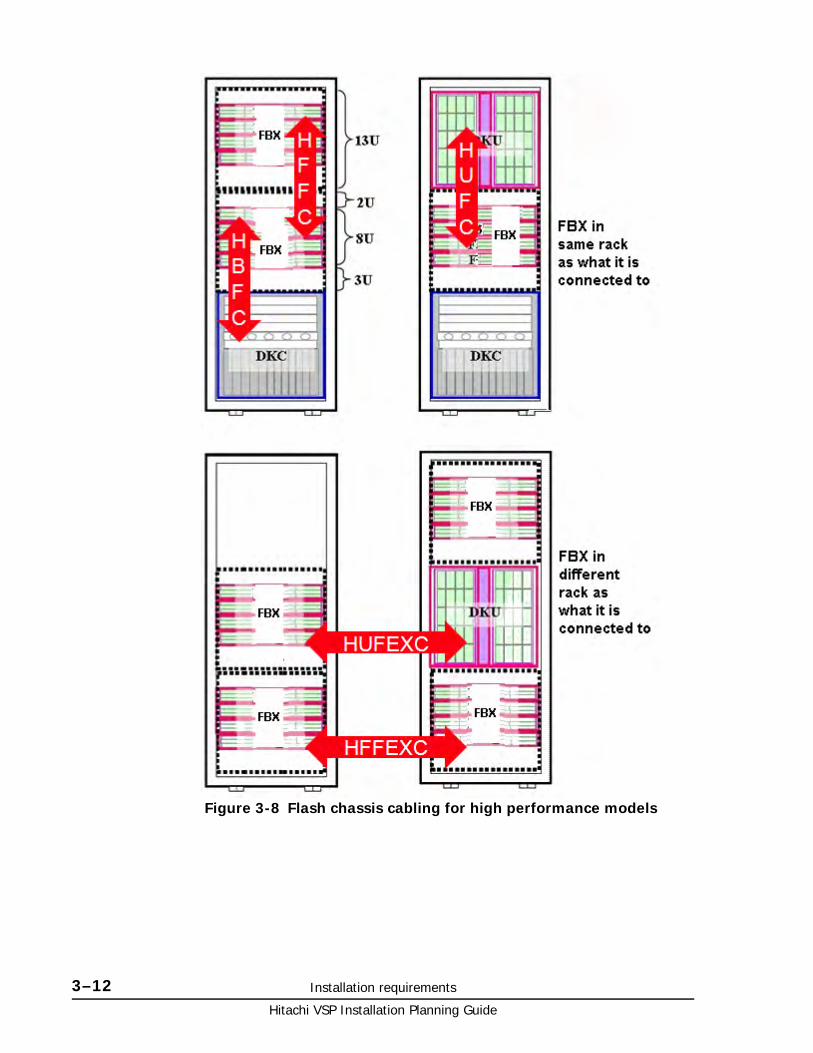
Flash chassis cabling
The following illustrations show the correct way to connect the ENC adapters to the controller chassis.
Figure 3-6 Incorrect breaker configurations for the controller rack
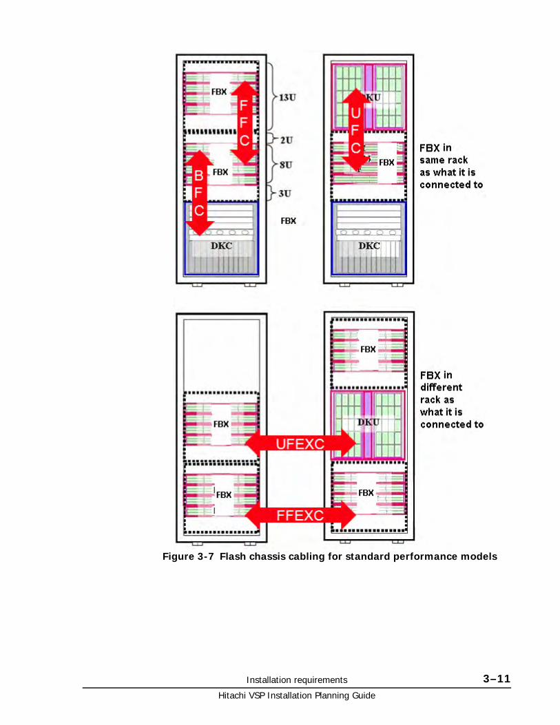
Installation requirements 3–11Hitachi VSP Installation Planning Guide
Figure 3-7 Flash chassis cabling for standard performance models
Hitachi VSP Installation Planning Guide
3–12 Installation requirements
Figure 3-8 Flash chassis cabling for high performance models

Installation requirements 3–13Hitachi VSP Installation Planning Guide
Environmental specificationsThe following table lists the environmental specifications of the VSP storage system.
Table 3-9 Virtual Storage Platform Environmental specifications
Item Operating Not Operating In Storage
Temperature
(ºF / ºC)
60.8 - 89.6 /
16 to 32
-18 - 109.4
-10 to 43
-45 - 140
-25 to 60
Relative Humidity (%)4
20 to 80 8 to 90 5 to 95
Max. Wet Bulb
(ºF / ºC)
78.8 / 26 80.6 / 27 84.2 / 29
Temperature Deviation per hour
(ºF / ºC)
18 / 10 18 / 10 36 / 20
Vibration
to 10Hz: 0.25 mm
10 to 300 Hz
0.49 m/s2
5 to 10 Hz: 2.5 mm
10 to 70 Hz: 4.9 m/s2
70 to 99 Hz: 0.05 mm
99 to 300 Hz: 9.8 m/s2
Sine Vibration:
4.9 m/s2, 5 min.
At the resonant frequency with the highest displacement found between 3 to 100 Hz 6
Random Vibration:
0.147 m2/s3
30 min, 5 to 100 Hz 7
Earthquake
resistance (m/s2)Up to 2.5 10 - -
Shock - 78.4 m/s2, 15 ms Horizontal:
Incline Impact 1.22 m/s8
Vertical:
Rotational Edge 0.15 m9
Altitude -60 m to 3,000 m -
Notes:
1. Environmental specification for operating condition should be satisfied before the storage system is powered on. Maximum temperature of 32°C should be strictly satisfied at air inlet portion.
2. Recommended temperature range is 21 to 24°C
3. Non-operating condition includes both packing and unpacking conditions unless otherwise specified.
4. On shipping/storage condition, the product should be packed with factory packing
5. No condensation in and around the drive should be observed under any conditions. No condensation in and around the drive should be observed under any conditions.
6. The above specifications of vibration are applied to all three axes
7. See ASTM D999-01 The Methods for Vibration Testing of Shipping Containers.
8. See ASTM D5277-92 Test Method for Performing Programmed Horizontal Impacts Using an Inclined Impact Tester.
9. See ASTM D6055-96 Test Methods for Mechanical Handling of Unitized Loads and Large Shipping Cases and Crates.
10. Time is 5 seconds or less in case of the testing with device resonance point (6 to 7Hz.
Hitachi VSP Installation Planning Guide
3–14 Installation requirements
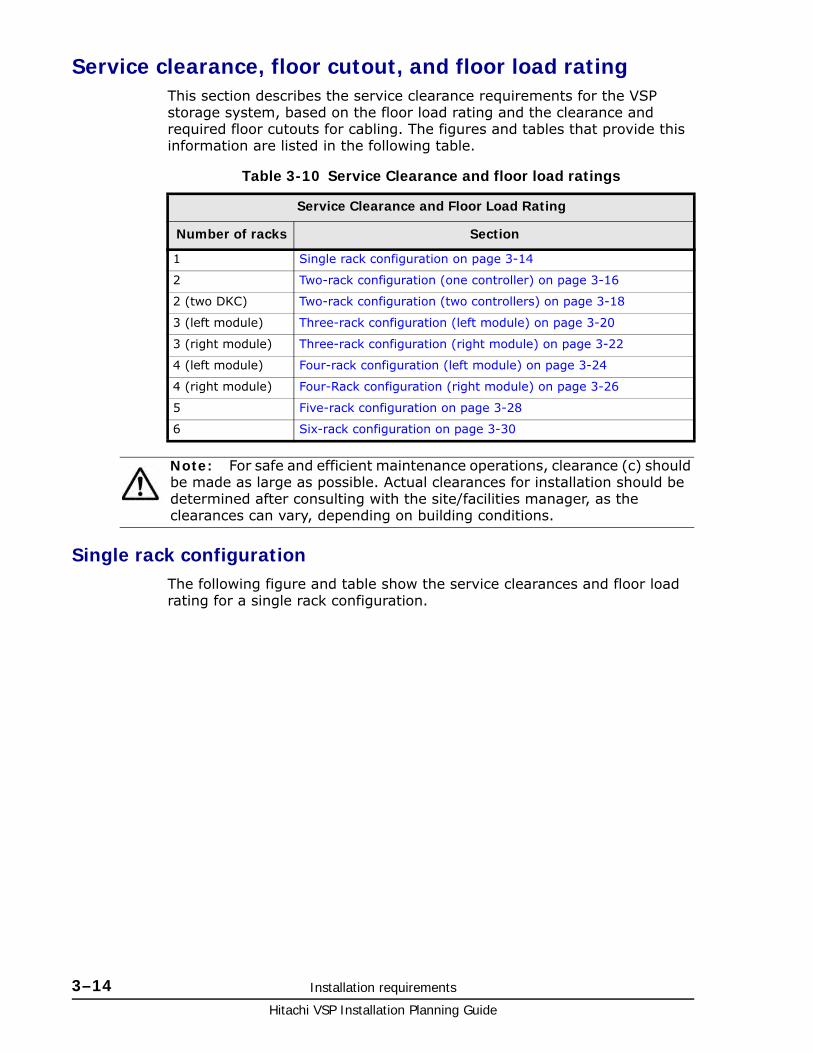
Service clearance, floor cutout, and floor load ratingThis section describes the service clearance requirements for the VSP storage system, based on the floor load rating and the clearance and required floor cutouts for cabling. The figures and tables that provide this information are listed in the following table.
Table 3-10 Service Clearance and floor load ratings
Single rack configurationThe following figure and table show the service clearances and floor load rating for a single rack configuration.
Service Clearance and Floor Load Rating
Number of racks Section
1 Single rack configuration on page 3-14
2 Two-rack configuration (one controller) on page 3-16
2 (two DKC) Two-rack configuration (two controllers) on page 3-18
3 (left module) Three-rack configuration (left module) on page 3-20
3 (right module) Three-rack configuration (right module) on page 3-22
4 (left module) Four-rack configuration (left module) on page 3-24
4 (right module) Four-Rack configuration (right module) on page 3-26
5 Five-rack configuration on page 3-28
6 Six-rack configuration on page 3-30
Note: For safe and efficient maintenance operations, clearance (c) should be made as large as possible. Actual clearances for installation should be determined after consulting with the site/facilities manager, as the clearances can vary, depending on building conditions.

Installation requirements 3–15Hitachi VSP Installation Planning Guide
Figure 3-9 Service Clearances, single rack system

Hitachi VSP Installation Planning Guide
3–16 Installation requirements
Table 3-11 Floor load rating and required clearances for single-rack configuration
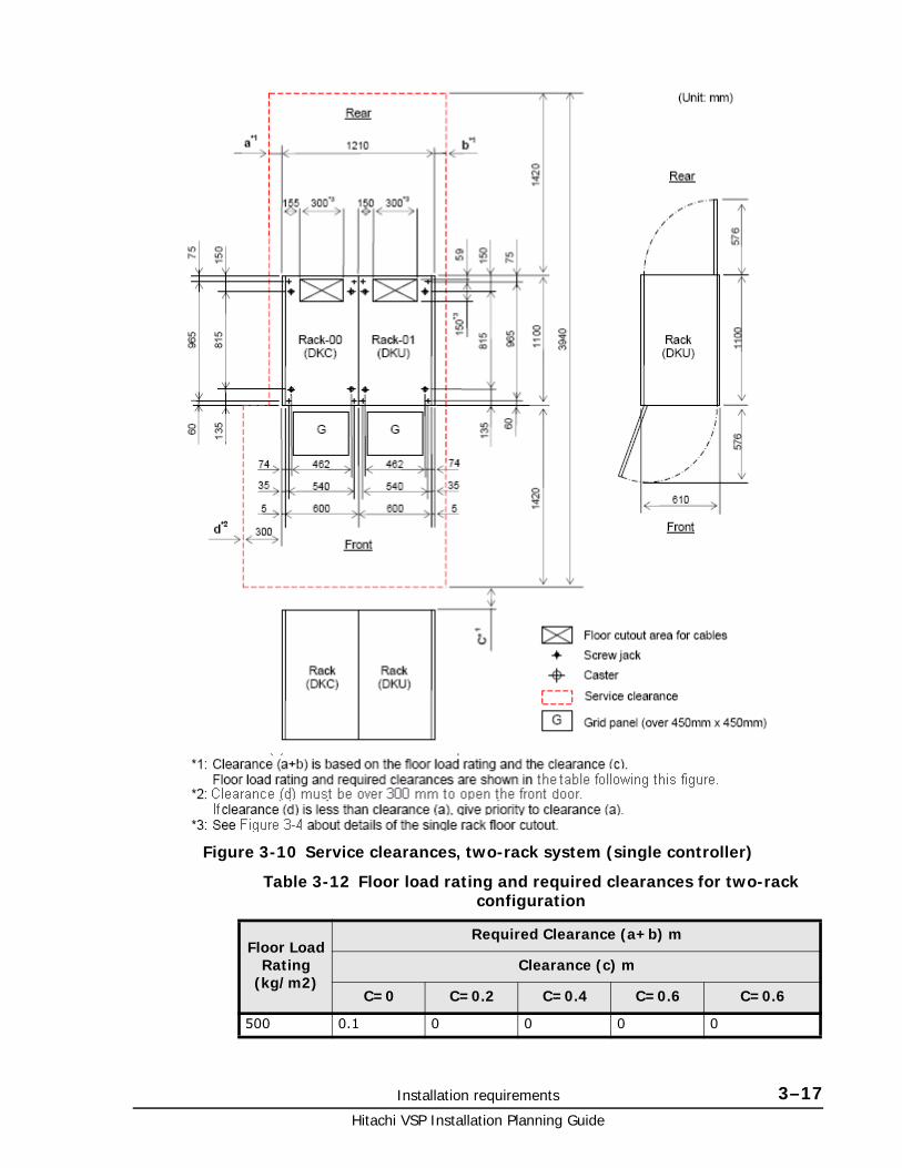
Two-rack configuration (one controller)The following figure and table shows the service clearances and floor load rating for a two-rack configuration.
Floor LoadRating
(kg/m2)
Required Clearance (a+b) m
Clearance (c) m
C=0 C=0.2 C=0.4 C=0.6 C=0.6
500 0. 1 0 0 0
450 0.2 0.1 0.1 0 0
400 0.3 0.3 0.2 0.1 0.1
350 0.5 0.4 0.4 0.3 0.2
300 0.9 0.8 0.7 0.6 0.4
Notes:
1. Actual clearances for installation should be determined after consulting with construction specialist responsible for installation building, as they could vary depending on the size/layout of the system and building conditions.
2. When various configurations of storage systems are arranged in a row, clearance values based on the largest storage system configuration should be used.
3. From the viewpoint of maintenance operations, it is suggested that Clearance (c) be made as large as possible.
Installation requirements 3–17Hitachi VSP Installation Planning Guide
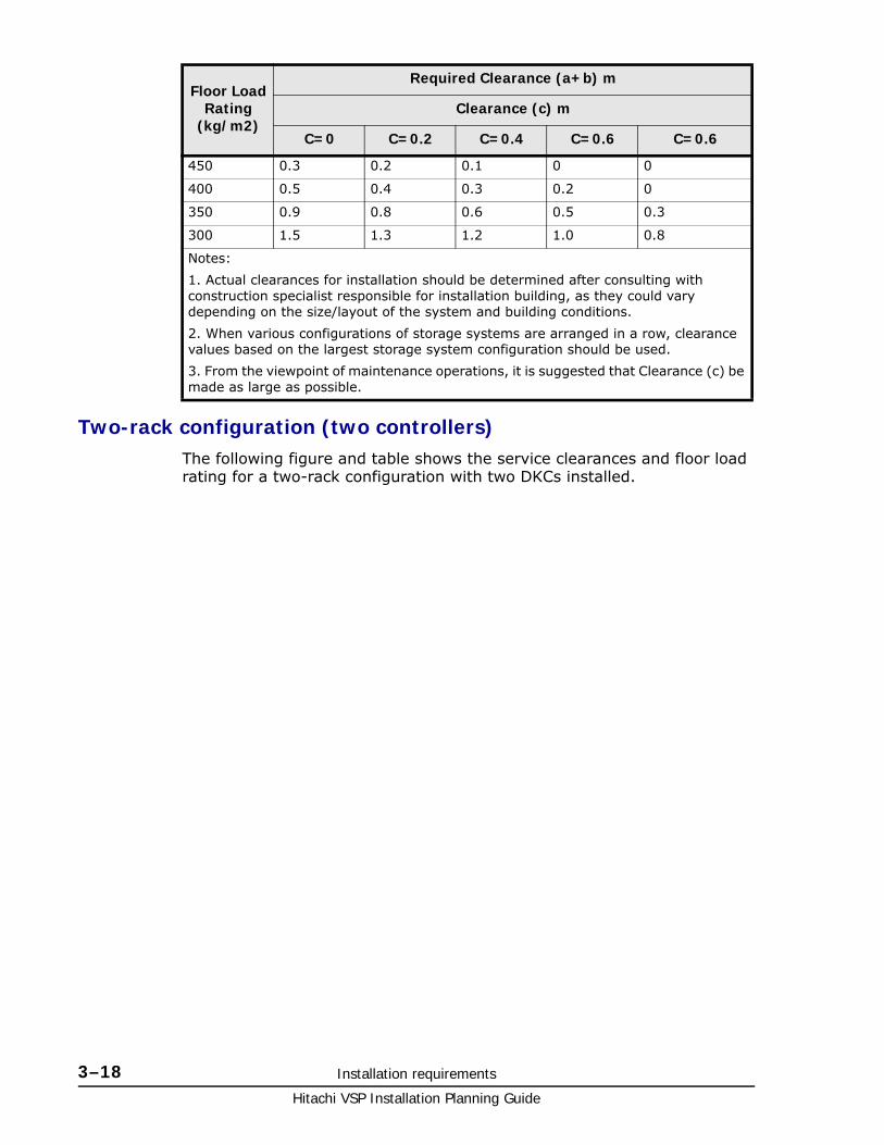
Table 3-12 Floor load rating and required clearances for two-rack configuration
Figure 3-10 Service clearances, two-rack system (single controller)
Floor LoadRating
(kg/m2)
Required Clearance (a+b) m
Clearance (c) m
C=0 C=0.2 C=0.4 C=0.6 C=0.6
500 0.1 0 0 0 0
Hitachi VSP Installation Planning Guide
3–18 Installation requirements
Two-rack configuration (two controllers)The following figure and table shows the service clearances and floor load rating for a two-rack configuration with two DKCs installed.
450 0.3 0.2 0.1 0 0
400 0.5 0.4 0.3 0.2 0
350 0.9 0.8 0.6 0.5 0.3
300 1.5 1.3 1.2 1.0 0.8
Notes:
1. Actual clearances for installation should be determined after consulting with construction specialist responsible for installation building, as they could vary depending on the size/layout of the system and building conditions.
2. When various configurations of storage systems are arranged in a row, clearance values based on the largest storage system configuration should be used.
3. From the viewpoint of maintenance operations, it is suggested that Clearance (c) be made as large as possible.
Floor LoadRating
(kg/m2)
Required Clearance (a+b) m
Clearance (c) m
C=0 C=0.2 C=0.4 C=0.6 C=0.6

Installation requirements 3–19Hitachi VSP Installation Planning Guide
Figure 3-11 Service clearances, two-rack system (two controllers)

Hitachi VSP Installation Planning Guide
3–20 Installation requirements
Table 3-13 Floor load rating and required clearances for two-rack configuration (two controllers)
Three-rack configuration (left module)The following figure and table shows the service clearances and floor load rating for a three-rack configuration.
Floor LoadRating
(kg/m2)
Required Clearance (a+b) m
Clearance (c) m
C=0 C=0.2 C=0.4 C=0.6 C=0.6
500 0.1 0 0 0 0
450 0.3 0.2 0.1 0 0
400 0.5 0.4 0.3 0.2 0
350 0.9 0.8 0.6 0.5 0.3
300 1.5 1.3 1.2 1.0 0.8
Notes:
1. Actual clearances for installation should be determined after consulting with construction specialist responsible for installation building, as they could vary depending on the size/layout of the system and building conditions.
2. When various configurations of storage systems are arranged in a row, clearance values based on the largest storage system configuration should be used.
3. From the viewpoint of maintenance operations, it is suggested that Clearance (c) be made as large as possible.

Installation requirements 3–21Hitachi VSP Installation Planning Guide
Table 3-14 Floor load rating and required clearances for the three-rack Configuration (left module)
Figure 3-12 Service clearances, three-rack system (left module)
Floor LoadRating
(kg/m2)
Required Clearance (a+b) m
Clearance (c) m
C=0 C=0.2 C=0.4 C=0.6 C=0.6
500 0.1 0 0 0 0
450 0.4 0.2 0.1 0 0
400 0.8 0.6 0.4 0.3 0
Hitachi VSP Installation Planning Guide
3–22 Installation requirements
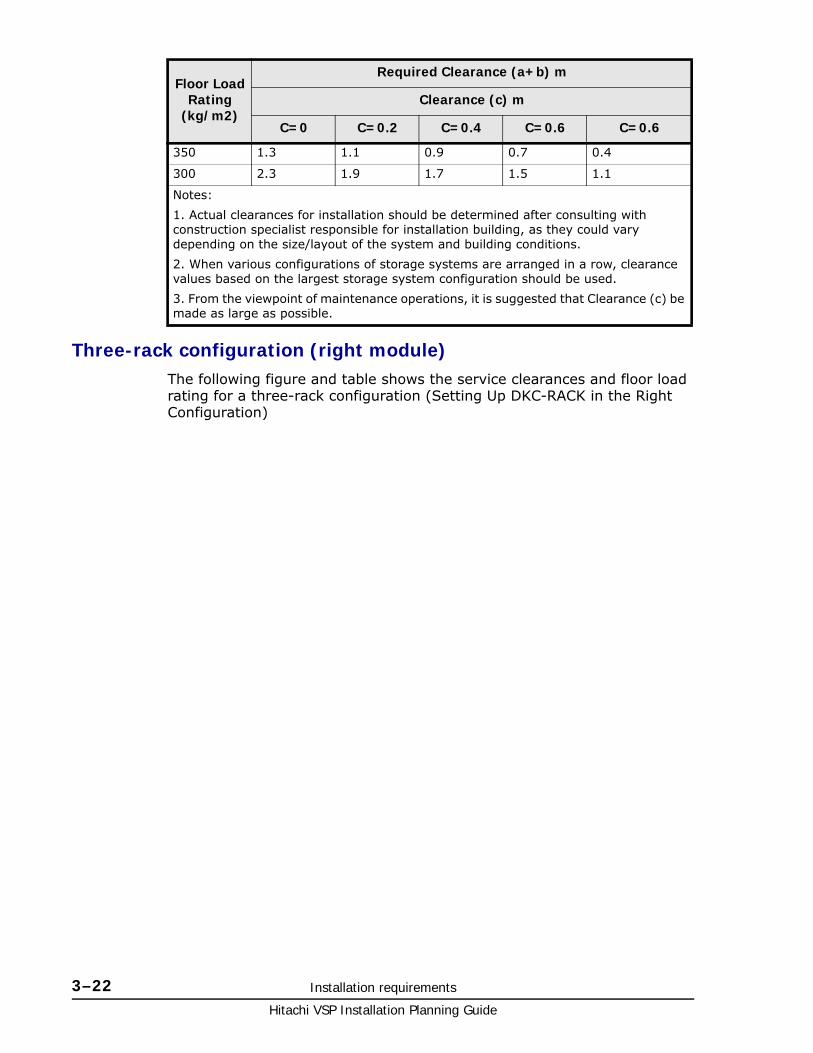
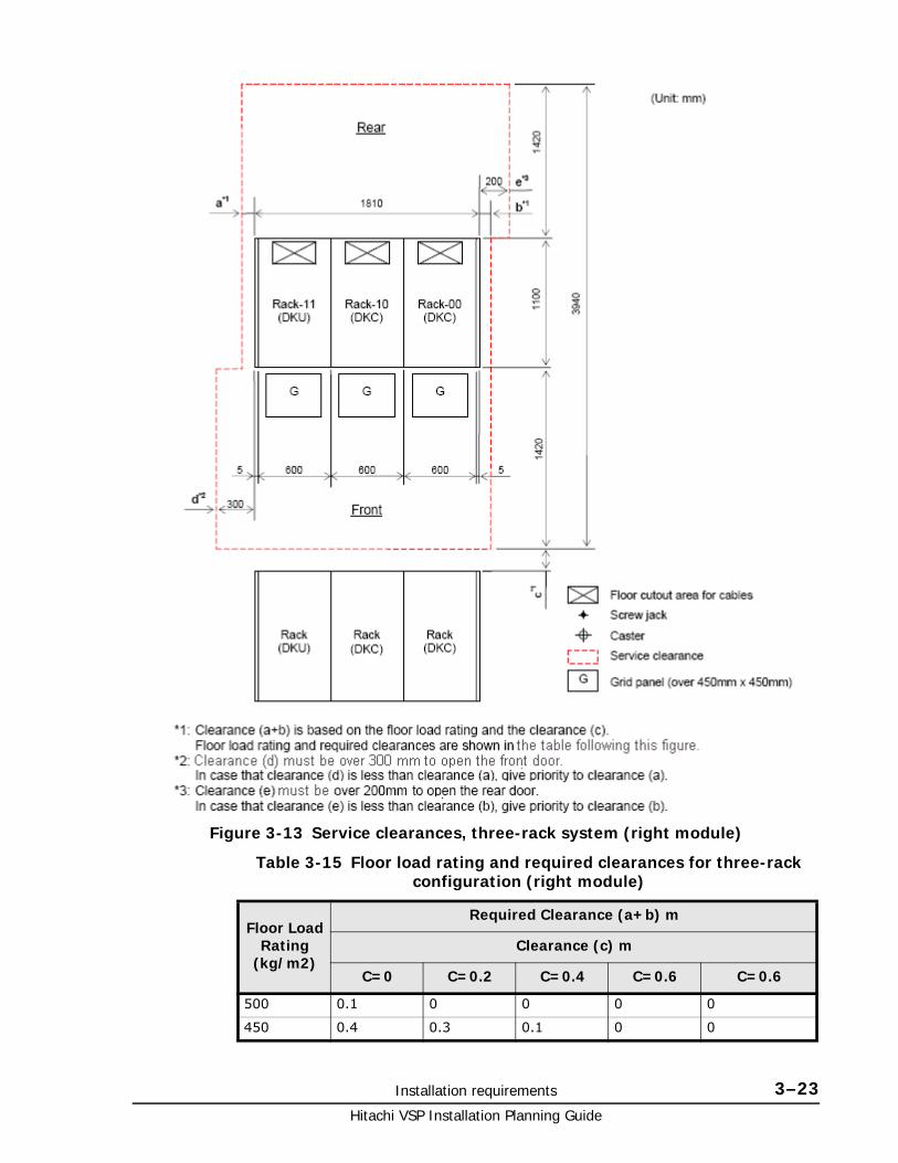
Three-rack configuration (right module)The following figure and table shows the service clearances and floor load rating for a three-rack configuration (Setting Up DKC-RACK in the Right Configuration)
350 1.3 1.1 0.9 0.7 0.4
300 2.3 1.9 1.7 1.5 1.1
Notes:
1. Actual clearances for installation should be determined after consulting with construction specialist responsible for installation building, as they could vary depending on the size/layout of the system and building conditions.
2. When various configurations of storage systems are arranged in a row, clearance values based on the largest storage system configuration should be used.
3. From the viewpoint of maintenance operations, it is suggested that Clearance (c) be made as large as possible.
Floor LoadRating
(kg/m2)
Required Clearance (a+b) m
Clearance (c) m
C=0 C=0.2 C=0.4 C=0.6 C=0.6
Installation requirements 3–23Hitachi VSP Installation Planning Guide
Table 3-15 Floor load rating and required clearances for three-rack configuration (right module)
Figure 3-13 Service clearances, three-rack system (right module)
Floor LoadRating
(kg/m2)
Required Clearance (a+b) m
Clearance (c) m
C=0 C=0.2 C=0.4 C=0.6 C=0.6
500 0.1 0 0 0 0
450 0.4 0.3 0.1 0 0

Hitachi VSP Installation Planning Guide
3–24 Installation requirements
Four-rack configuration (left module)The following figure and table shows the service clearances and floor load rating for a four-rack configuration (Setting up DKC rack in the left configuration)
400 0.8 0.6 0.5 0.3 0 .1
350 1.4 1.2 1.0 0.8 0.5
300 2.3 2.0 1.8 1.5 1.2
Notes:
1. Actual clearances for installation should be determined after consulting with construction specialist responsible for installation building, as they could vary depending on the size/layout of the system and building conditions.
2. When various configurations of storage systems are arranged in a row, clearance values based on the largest storage system configuration should be used.
3. From the viewpoint of maintenance operations, it is suggested that Clearance (c) be made as large as possible.
Floor LoadRating
(kg/m2)
Required Clearance (a+b) m
Clearance (c) m
C=0 C=0.2 C=0.4 C=0.6 C=0.6

Installation requirements 3–25Hitachi VSP Installation Planning Guide
Table 3-16 Floor load rating and required clearances for four-rack configuration (left module)
Figure 3-14 Service clearances, four-rack system (left module)
Floor LoadRating
(kg/m2)
Required Clearance (a+b) m
Clearance (c) m
C=0 C=0.2 C=0.4 C=0.6 C=0.6
500 0.1 0 0 0 0
450 0.5 0.3 0.1 0 0
400 1.1 0.8 0.6 0.4 0 .1

Hitachi VSP Installation Planning Guide
3–26 Installation requirements
Four-Rack configuration (right module)The following figure and table shows the service clearances and floor load rating for a four-rack configuration (setting up a controller rack in the right configuration)
350 1.8 1.5 1.2 1.0 0.6
300 3.0 2.6 2.3 2.0 1.5
Notes:
1. Actual clearances for installation should be determined after consulting with construction specialist responsible for installation building, as they could vary depending on the size/layout of the system and building conditions.
2. When various configurations of storage systems are arranged in a row, clearance values based on the largest storage system configuration should be used.
3. From the viewpoint of maintenance operations, it is suggested that Clearance (c) be made as large as possible.
Floor LoadRating
(kg/m2)
Required Clearance (a+b) m
Clearance (c) m
C=0 C=0.2 C=0.4 C=0.6 C=0.6

Installation requirements 3–27Hitachi VSP Installation Planning Guide
Table 3-17 Floor load rating and required clearances for four-rack configuration (right module)
Figure 3-15 Service clearances, four-rack system (right module)
Floor LoadRating
(kg/m2)
Required Clearance (a+b) m
Clearance (c) m
C=0 C=0.2 C=0.4 C=0.6 C=0.6
500 0.1 0 0 0 0
450 0.5 0.3 0.1 0 0

Hitachi VSP Installation Planning Guide
3–28 Installation requirements
Five-rack configurationThis following figure and table shows the service clearances and floor load rating for a five-rack configuration.
400 1.1 0.8 0.6 0.4 0 .1
350 1.8 1.5 1.2 1.0 0.6
300 3.0 2.6 2.3 2.0 1.5
Notes:
1. Actual clearances for installation should be determined after consulting with construction specialist responsible for installation building, as they could vary depending on the size/layout of the system and building conditions.
2. When various configurations of storage systems are arranged in a row, clearance values based on the largest storage system configuration should be used.
3. From the viewpoint of maintenance operations, it is suggested that Clearance (c) be made as large as possible.
Floor LoadRating
(kg/m2)
Required Clearance (a+b) m
Clearance (c) m
C=0 C=0.2 C=0.4 C=0.6 C=0.6

Installation requirements 3–29Hitachi VSP Installation Planning Guide
Table 3-18 Floor load rating and required clearances for five-rack configuration
Figure 3-16 Service clearances, five-rack System
Floor LoadRating
(kg/m2)
Required Clearance (a+b) m
Clearance (c) m
C=0 C=0.2 C=0.4 C=0.6 C=0.6
500 0.1 0 0 0 0
Hitachi VSP Installation Planning Guide
3–30 Installation requirements
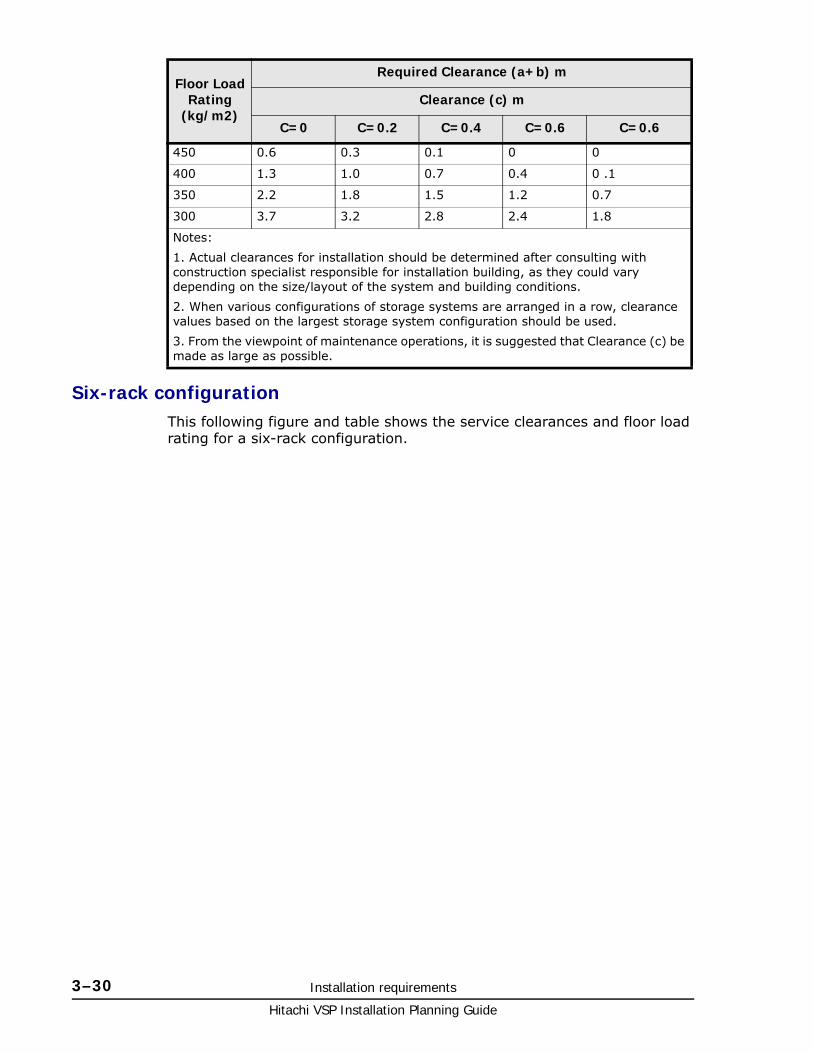
Six-rack configurationThis following figure and table shows the service clearances and floor load rating for a six-rack configuration.
450 0.6 0.3 0.1 0 0
400 1.3 1.0 0.7 0.4 0 .1
350 2.2 1.8 1.5 1.2 0.7
300 3.7 3.2 2.8 2.4 1.8
Notes:
1. Actual clearances for installation should be determined after consulting with construction specialist responsible for installation building, as they could vary depending on the size/layout of the system and building conditions.
2. When various configurations of storage systems are arranged in a row, clearance values based on the largest storage system configuration should be used.
3. From the viewpoint of maintenance operations, it is suggested that Clearance (c) be made as large as possible.
Floor LoadRating
(kg/m2)
Required Clearance (a+b) m
Clearance (c) m
C=0 C=0.2 C=0.4 C=0.6 C=0.6
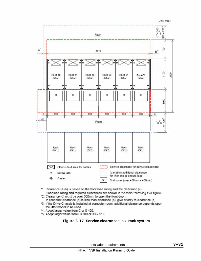
Installation requirements 3–31Hitachi VSP Installation Planning Guide
Figure 3-17 Service clearances, six-rack system

Hitachi VSP Installation Planning Guide
3–32 Installation requirements
Table 3-19 Floor load rating and required clearances for six-rack configuration
Operational requirementsThe operational requirements for the VSP include:
• LAN for Storage Navigator
Storage Navigator communicates with the VSP storage system over a LAN to obtain system configuration and status information and send user commands to the storage system. Storage Navigator serves as the integrated interface for all resource manager components.
• Cable length for front-end directors
Table 3-20 Maximum cable length (shortwave) on page 3-32 lists the cable length requirements for the FEDs in the VSP storage system.
Table 3-20 Maximum cable length (shortwave)
• External data storage
If you plan to attach external storage to the VSP storage system, be sure to include the appropriate power and space requirements in your planning.
Floor LoadRating
(kg/m2)
Required Clearance (a+b) m
Clearance (c) m
C=0 C=0.2 C=0.4 C=0.6 C=0.6
500 0.1 0 0 0 0
450 0.7 0.4 0.1 0 0
400 1.5 1.1 0.8 0.5 0 .1
350 2.6 2.2 1.8 1.4 0.9
300 4.4 3.8 3.3 2.9 2.1
Notes:
1. Actual clearances for installation should be determined after consulting with construction specialist responsible for installation building, as they could vary depending on the size/layout of the system and building conditions.
2. When various configurations of storage systems are arranged in a row, clearance values based on the largest storage system configuration should be used.
3. From the viewpoint of maintenance operations, it is suggested that Clearance (c) be made as large as possible.
DataTransferRate
OM1(62.5/125ƒÝm multi-mode fiber)
OM2(50/125ƒÝm multi-mode fiber)
OM3(50/125ƒÝm laser optimizedmulti-mode fiber)
MB/s feet / meters feet / meters feet / meters
100 984.3 / 300 1640.4 / 500 1640.4 / 500
200 492.1 / 150 984.3 / 300 1640.4 / 500
400 229.7 / 70 492.1 / 150 1246.7 / 380
800 68.9 / 21 164 / 50 492.1 / 150
CA KD E F G H I J L M N O P Q R S T U V W X Y# B ZA B C D F G J K L M P R S T V
Glossary–1Hitachi VSP Installation Planning Guide
Glossary
This glossary defines the special terms used in this document.
A
ATA
Advanced Technology Attachment. This is a disk drive implementation that integrates the controller on the disk drive.
array
See disk array.
B
back-end director (BED)
The hardware component that controls the transfer of data between the drives and cache. A BED feature consists of a pair of boards. A BED is also referred to as a disk adapter (DKA).
BED
See back-end director.
BS
basic (power) supply
C
CCI
Command Control Interface
CHA
See channel adapter.

CA KD E F G H I J L M N O P Q R S T U V W X Y# B ZA B C D F G J K L M P R S T V
Hitachi VSP Installation Planning Guide
Glossary–2
controller chassis
The hardware assembly that contains the logic and processing components of the Virtual Storage Platform storage system, including the front-end directors, virtual storage directors, cache memory, switches, and back-end directors. The Virtual Storage Platform storage system can be configured with one or two control chassis.
D
disk array
Disk array, or just array, is a complete storage system, including the control and logic devices, storage devices (HDD, SSD), connecting cables, and racks.
drive chassis
The hardware component of the Virtual Storage Platform that houses disk drives and/or flash drives. The Virtual Storage Platform can be configured with up to 16 drive chassis.
dynamic provisioning
An approach to managing storage. Instead of “reserving” a fixed amount of storage, it removes capacity from the available pool when data is actually written to disk. Also called thin provisioning.
F
FED
See front-end director.
FICON
Fibre Connectivity
flash drive
A data drive that is a solid-state memory device instead of a rotating hard disk.
free capacity
The amount of storage space (in bytes) that is available for use by the host systems.
front-end director (FED)
The hardware component that processes channel commands from hosts and manages host access to cache.

CA KD E F G H I J L M N O P Q R S T U V W X Y# B ZA B C D F G J K L M P R S T V
Glossary–3Hitachi VSP Installation Planning Guide
G
GLPR
global logical partition
J
JRE
Java Runtime Environment
JVM
Java Virtual Machine
K
kVA
kilovolt-ampere
L
LDEV
logical device
license key
A specific set of characters that unlocks an application and allows it to be used.
logical device (LDEV)
An individual logical data volume (on multiple drives in a RAID configuration) in the storage system. An LDEV may or may not contain any data and may or may not be defined to any hosts. Each LDEV has a unique identifier or “address” within the storage system composed of the logical disk controller (LDKC) number, control unit (CU) number, and LDEV number. The LDEV IDs within a storage system do not change.An LDEV formatted for use by mainframe hosts is called a logical volume image (LVI). An LDEV formatted for use by open-system hosts is called a logical unit (LU).
logical volume
See volume.
logical volume image (LVI)
A logical volume that is configured for use by mainframe hosts (for example, 3390-9).

CA KD E F G H I J L M N O P Q R S T U V W X Y# B ZA B C D F G J K L M P R S T V
Hitachi VSP Installation Planning Guide
Glossary–4
LUN
logical unit number
LUSE
LUN Size Expansion
LVI
See logical volume image (LVI).
M
mirror
In Universal Replicator, each pair relationship in and between journal groups is called a “mirror”. Each pair is assigned a mirror ID when it is created. The mirror ID identifies individual pair relationships between journal groups.
modify mode
The mode of operation of Storage Navigator that allows changes to the storage system configuration. See also view mode.
P
pair
Two logical volumes in a replication relationship in which one volume contains original data to be copied and the other volume contains the copy of the original data. The copy operations can be synchronous or asynchronous, and the pair volumes can be located in the same storage system (in-system replication) or in different storage systems (remote replication).
pair status
Indicates the condition of a copy pair. A pair must have a specific status for specific operations. When an operation completes, the status of the pair changes to the new status.
PDB
power distribution box
PDP
power distribution panel
PDU
power distribution unit

CA KD E F G H I J L M N O P Q R S T U V W X Y# B ZA B C D F G J K L M P R S T V
Glossary–5Hitachi VSP Installation Planning Guide
pool
A set of volumes that are reserved for storing Copy-on-Write Snapshot data or Dynamic Provisioning write data.
R
RAID
redundant array of independent disks. A disk array in which part of the physical storage space is used to store user data and parity information, and another part is used to store a duplicate set of user data and parity information. This redundant configuration prevents data loss in case a disk drive within the RAID configuration fails, and enables regeneration of user data in the event that one of the array's member disks or the access path to it fails.
RAID group
A set of RAID disks that have the same capacity and are treated as one group for data storage and recovery. A RAID group contains both user data and parity information. This allows user data to be accessed in the event that one or more of the drives within the RAID group are not available. The RAID level of a RAID group determines the number of data drives and parity drives and how the data is “striped” across the drives. For RAID1, user data is duplicated within the RAID group, so there is no parity data for RAID1 RAID groups.
A RAID group can also be called an array group or a parity group.
RAID level
The type of RAID implementation. RAID levels include RAID0, RAID1, RAID2, RAID3, RAID4, RAID5 and RAID6.
S
SAS
serial-attached SCSI
SATA
serial Advanced Technology Attachment
service information message (SIM)
SIMs are generated by a VSP storage system when it detects an error or service requirement. SIMs are reported to hosts and displayed on Storage Navigator.
SFM
See smart flash module

CA KD E F G H I J L M N O P Q R S T U V W X Y# B ZA B C D F G J K L M P R S T V
Hitachi VSP Installation Planning Guide
Glossary–6
SIM
See service information message
smart flash module
The smart flash module (SFM) is a Hitachi custom-designed and manufactured enterprise class solid state storage module. It uses a high performance, custom ASIC flash controller and standard flash memory chips in an implementation that exceeds the performance of expensive SLC SSDs, but costs less than less expensive MLC SSDs. .
SOM
See system option mode
system disk
The volume from which an open-systems host boots.
system option mode (SOM)
Additional operational parameters for the RAID storage systems that enable the storage system to be tailored to unique customer operating requirements. SOMs are set on the service processor.
T
tiered storage
A layered structure of performance levels, or tiers, that matches data access requirements with the appropriate performance tiers. The tiers are:
Tier 1: Static content. Tier 1 is fully supported computing expected to be production quality.
Tier 2: Application logic. Tier 2 platforms are not supported by the security officer and release engineering teams. Tier 2 systems are targeted for Tier 1 support, but are still under development.
Tier 3: Database. Tier 3 platforms are architectures for which hardware is not or will not be available or that are considered legacy systems unlikely to see broad future use.
Tier 4 systems are not supported.
V
virtual storage director
The virtual storage directors of the Virtual Storage Platform storage system control the front-end directors and manage front-end access to cache memory.

CA KD E F G H I J L M N O P Q R S T U V W X Y# B ZA B C D F G J K L M P R S T V
Glossary–7Hitachi VSP Installation Planning Guide
volume
A logical device (LDEV), or a set of concatenated LDEVs in the case of LUSE, that has been defined to one or more hosts as a single data storage unit. A mainframe volume is called a logical volume image (LVI), and an open-systems volume is called a logical unit. (LU).

CA KD E F G H I J L M N O P Q R S T U V W X Y# B ZA B C D F G J K L M P R S T V
Hitachi VSP Installation Planning Guide
Glossary–8

Index–1Hitachi VSP Installation Planning Guide
Index
Symbolschecklist 1-2clearances, equipment 3-2equipment clearances 3-2equipment weight 3-2guidelines
access by authorized personnel 2-2cabling 2-2earthquake safety 2-2electrical safety 2-3equipment modifications 2-2fire protection 2-2hazards 2-2loose clothing 2-2moving equipment 2-3operating in storms 2-2power cables 2-3safety glasses 2-2walkways and floors 2-2warning and safety labels 2-2work safety 2-2
requirements 3-4cable length 3-32circuit breakers 3-7data center 3-3delivery 1-3facilities 1-4general 2-2grounding 3-6installation 1-2, 3-1LAN 3-32operational 1-4, 3-32plugs 3-7power 1-4power connection 3-6safety 1-2, 1-3, 2-1service clearance 3-14site 3-2storage 1-4, 3-3
responsibilitiessupport team 1-2
respopnsibilities
user 1-2specifications 3-4
electrical 3-5environmental 3-13load rating 3-14mechanical 3-4

Hitachi VSP Installation Planning Guide
Index–2

Hitachi VSP Installation Planning Guide
MK-90RD7041-09
Hitachi Data Systems
Corporate Headquarters2845 Lafayette StreetSanta Clara, California 95050-2639U.S.A.www.hds.com
Regional Contact Information
Americas+1 408 970 [email protected]
Europe, Middle East, and Africa+44 (0)1753 [email protected]
Asia Pacific+852 3189 [email protected]