hkd push-in anchor, single anchor application · pdf filehkd push-in anchor single anchor...
TRANSCRIPT
HKD Push-in anchor Single anchor application
10 / 2012
230
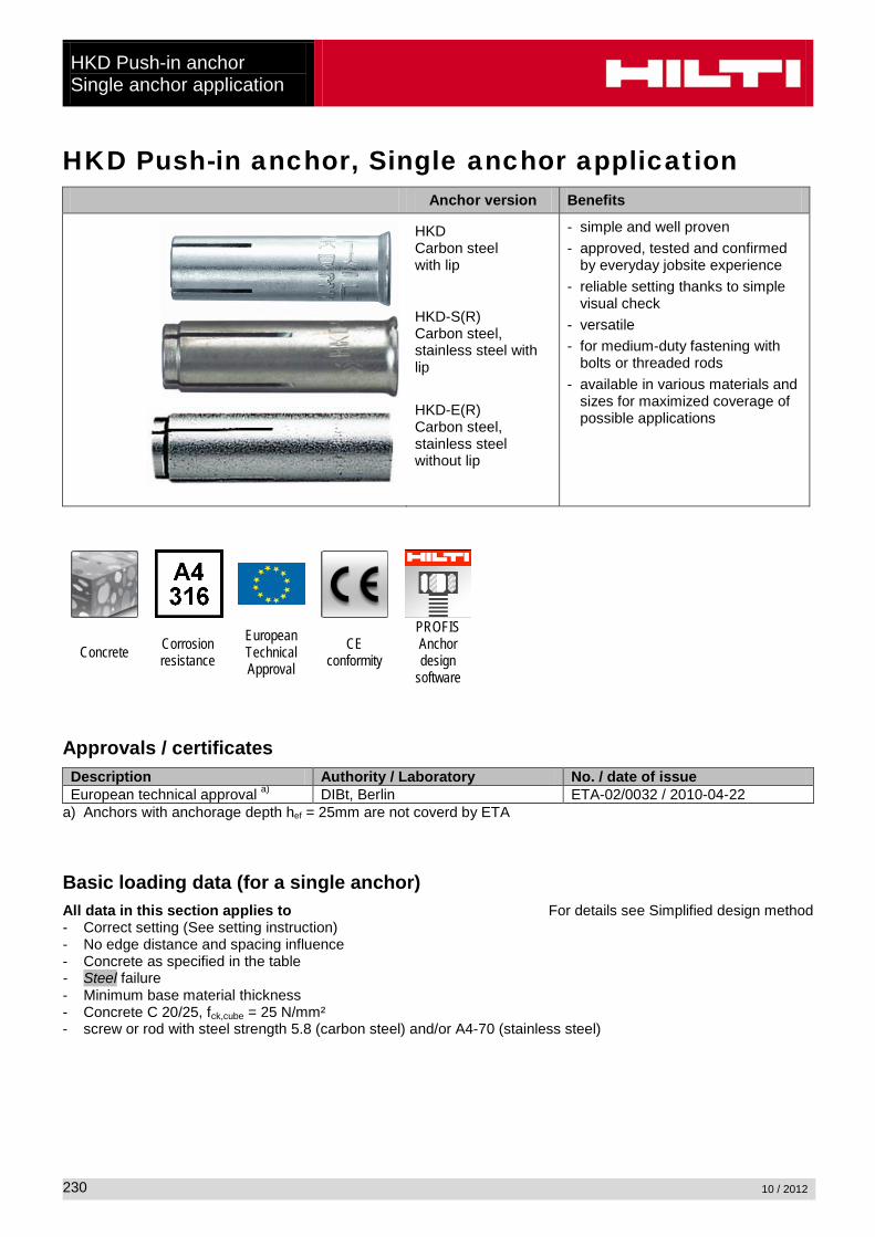
HKD Push-in anchor, Single anchor application Anchor version Benefits
HKD Carbon steel with lip
HKD-S(R) Carbon steel, stainless steel with lip
HKD-E(R) Carbon steel, stainless steel without lip
- simple and well proven - approved, tested and confirmed
by everyday jobsite experience - reliable setting thanks to simple
visual check - versatile - for medium-duty fastening with
bolts or threaded rods - available in various materials and
sizes for maximized coverage of possible applications
Concrete Corrosion resistance
European Technical Approval
CE conformity
PROFIS Anchor design
software
Approvals / certificates Description Authority / Laboratory No. / date of issue European technical approval a) DIBt, Berlin ETA-02/0032 / 2010-04-22
a) Anchors with anchorage depth hef = 25mm are not coverd by ETA Basic loading data (for a single anchor) All data in this section applies to For details see Simplified design method - Correct setting (See setting instruction) - No edge distance and spacing influence - Concrete as specified in the table - Steel failure - Minimum base material thickness - Concrete C 20/25, fck,cube = 25 N/mm² - screw or rod with steel strength 5.8 (carbon steel) and/or A4-70 (stainless steel)
HKD Push-in anchor
Single anchor application
10 / 2012
231
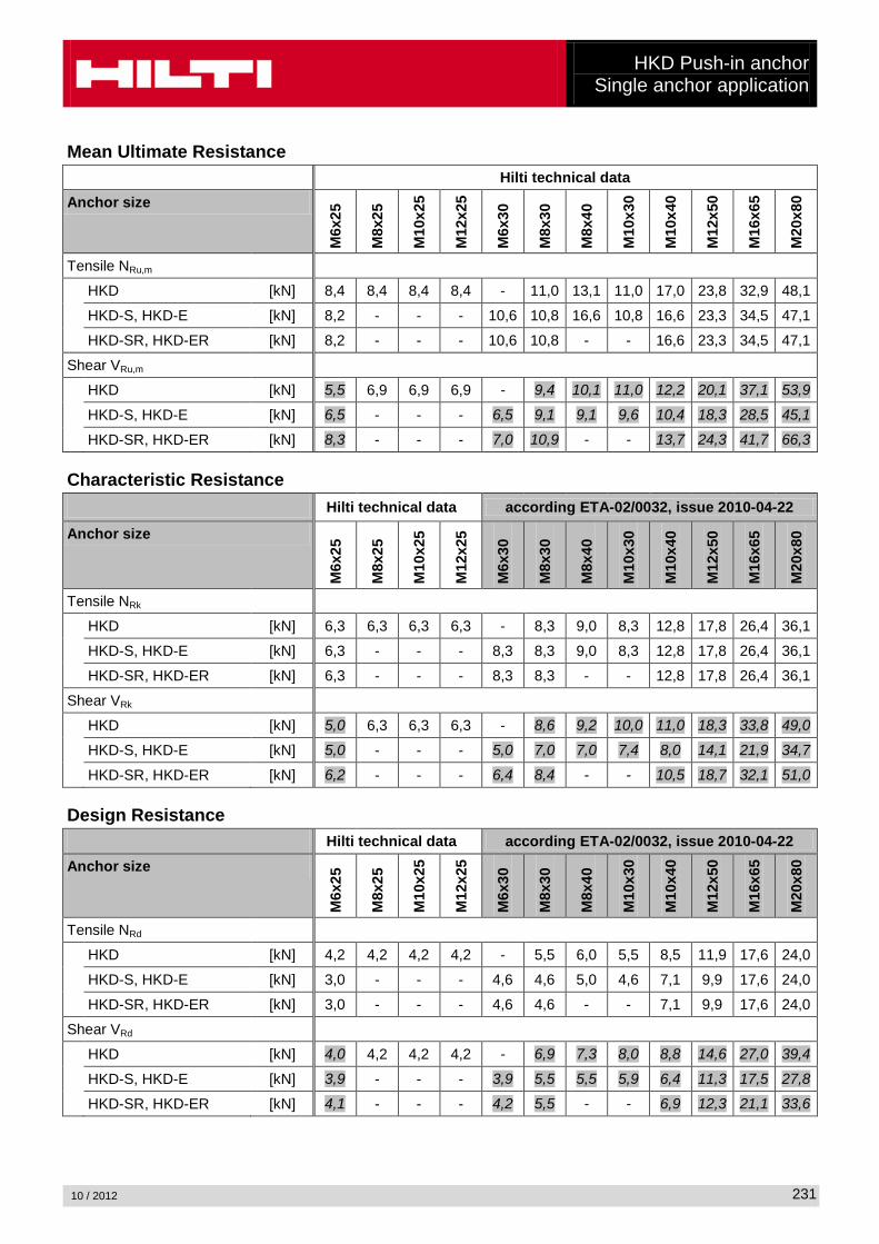
Mean Ultimate Resistance Hilti technical data Anchor size
M6x
25
M8x
25
M10
x25
M12
x25
M6x
30
M8x
30
M8x
40
M10
x30
M10
x40
M12
x50
M16
x65
M20
x80
Tensile NRu,m HKD [kN] 8,4 8,4 8,4 8,4 - 11,0 13,1 11,0 17,0 23,8 32,9 48,1
HKD-S, HKD-E [kN] 8,2 - - - 10,6 10,8 16,6 10,8 16,6 23,3 34,5 47,1
HKD-SR, HKD-ER [kN] 8,2 - - - 10,6 10,8 - - 16,6 23,3 34,5 47,1
Shear VRu,m HKD [kN] 5,5 6,9 6,9 6,9 - 9,4 10,1 11,0 12,2 20,1 37,1 53,9
HKD-S, HKD-E [kN] 6,5 - - - 6,5 9,1 9,1 9,6 10,4 18,3 28,5 45,1
HKD-SR, HKD-ER [kN] 8,3 - - - 7,0 10,9 - - 13,7 24,3 41,7 66,3 Characteristic Resistance Hilti technical data according ETA-02/0032, issue 2010-04-22
Anchor size
M6x
25
M8x
25
M10
x25
M12
x25
M6x
30
M8x
30
M8x
40
M10
x30
M10
x40
M12
x50
M16
x65
M20
x80
Tensile NRk HKD [kN] 6,3 6,3 6,3 6,3 - 8,3 9,0 8,3 12,8 17,8 26,4 36,1
HKD-S, HKD-E [kN] 6,3 - - - 8,3 8,3 9,0 8,3 12,8 17,8 26,4 36,1
HKD-SR, HKD-ER [kN] 6,3 - - - 8,3 8,3 - - 12,8 17,8 26,4 36,1
Shear VRk
HKD [kN] 5,0 6,3 6,3 6,3 - 8,6 9,2 10,0 11,0 18,3 33,8 49,0
HKD-S, HKD-E [kN] 5,0 - - - 5,0 7,0 7,0 7,4 8,0 14,1 21,9 34,7
HKD-SR, HKD-ER [kN] 6,2 - - - 6,4 8,4 - - 10,5 18,7 32,1 51,0 Design Resistance Hilti technical data according ETA-02/0032, issue 2010-04-22 Anchor size
M6x
25
M8x
25
M10
x25
M12
x25
M6x
30
M8x
30
M8x
40
M10
x30
M10
x40
M12
x50
M16
x65
M20
x80
Tensile NRd HKD [kN] 4,2 4,2 4,2 4,2 - 5,5 6,0 5,5 8,5 11,9 17,6 24,0
HKD-S, HKD-E [kN] 3,0 - - - 4,6 4,6 5,0 4,6 7,1 9,9 17,6 24,0
HKD-SR, HKD-ER [kN] 3,0 - - - 4,6 4,6 - - 7,1 9,9 17,6 24,0
Shear VRd
HKD [kN] 4,0 4,2 4,2 4,2 - 6,9 7,3 8,0 8,8 14,6 27,0 39,4
HKD-S, HKD-E [kN] 3,9 - - - 3,9 5,5 5,5 5,9 6,4 11,3 17,5 27,8
HKD-SR, HKD-ER [kN] 4,1 - - - 4,2 5,5 - - 6,9 12,3 21,1 33,6
HKD Push-in anchor Single anchor application
10 / 2012
232
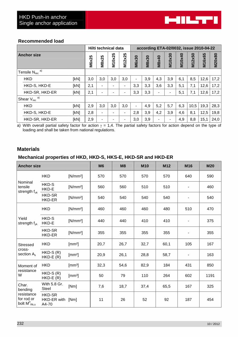
Recommended load Hilti technical data according ETA-02/0032, issue 2010-04-22 Anchor size
M6x
25
M8x
25
M10
x25
M12
x25
M6x
30
M8x
30
M8x
40
M10
x30
M10
x40
M12
x50
M16
x65
M20
x80
Tensile Nrec a) HKD [kN] 3,0 3,0 3,0 3,0 - 3,9 4,3 3,9 6,1 8,5 12,6 17,2
HKD-S, HKD-E [kN] 2,1 - - - 3,3 3,3 3,6 3,3 5,1 7,1 12,6 17,2
HKD-SR, HKD-ER [kN] 2,1 - - - 3,3 3,3 - - 5,1 7,1 12,6 17,2
Shear Vrec a)
HKD [kN] 2,9 3,0 3,0 3,0 - 4,9 5,2 5,7 6,3 10,5 19,3 28,3
HKD-S, HKD-E [kN] 2,8 - - - 2,8 3,9 4,2 3,9 4,6 8,1 12,5 19,8
HKD-SR, HKD-ER [kN] 2,9 - - - 3,0 3,9 - - 4,9 8,8 15,1 24,0 a) With overall partial safety factor for action γ = 1,4. The partial safety factors for action depend on the type of
loading and shall be taken from national regulations. Materials Mechanical properties of HKD, HKD-S, HKS-E, HKD-SR and HKD-ER
Anchor size M6 M8 M10 M12 M16 M20
Nominal tensile strength fuk
HKD [N/mm²] 570 570 570 570 640 590
HKD-S HKD-E [N/mm²] 560 560 510 510 - 460
HKD-SR HKD-ER [N/mm²] 540 540 540 540 - 540
Yield strength fyk
HKD [N/mm²] 460 460 460 480 510 470
HKD-S HKD-E [N/mm²] 440 440 410 410 - 375
HKD-SR HKD-ER [N/mm²] 355 355 355 355 - 355
Stressed cross-section As
HKD [mm²] 20,7 26,7 32,7 60,1 105 167
HKD-S (R) HKD-E (R) [mm²] 20,9 26,1 28,8 58,7 - 163
Moment of resistance W
HKD [mm³] 32,3 54,6 82,9 184 431 850
HKD-S (R) HKD-E (R) [mm³] 50 79 110 264 602 1191
Char. bending resistance for rod or bolt M0
Rk,s
With 5.8 Gr. Steel [Nm] 7,6 18,7 37,4 65,5 167 325
HKD-SR HKD-ER with A4-70
[Nm] 11 26 52 92 187 454

HKD Push-in anchor
Single anchor application
10 / 2012
233
Material quality Part Material
Anchor Body
HKD Steel Fe/Zn5 galvanised to min. 5 µm
HKD-S HKD-E Steel Fe/Zn5 galvanised to min. 5 µm
HKD-SR HKD-ER Stainless steel, 1.4401, 1.4404, 1.4571
Tapered expansion plug
HKD Steel material
HKD-S HKD-E Steel material
HKD-SR HKD-ER Stainless steel, 1.4401, 1.4404, 1.4571
Anchor dimensions Anchor size Anchor version HKD HKD-S (R) HKD-E (R) M
6x25
M8x
25
M10
x25
M12
x25
M6x
30
M8x
30
M8x
40
M10
x30
M10
x40
M12
x50
M16
x65
M20
x80
Effective anchorage depth hef [mm] 25 25 25 25 30 30 40 30 40 50 60 80
Anchor diameter d1 [mm] 7,9 9,95 11,9 14,9 8 9,95 9,95 11,8 11,95 14,9 19,75 24,75
Plug diameter d2 [mm] 5,1 6,35 8,1 9,7 5 6,5 6,35 8,2 8,2 10,3 13,8 16,4
Plug length l1 [mm] 10 7 7 7,2 15 12 16 12 16 20 29 30
Anchor body
HKD Push-in anchor Single anchor application
10 / 2012
234
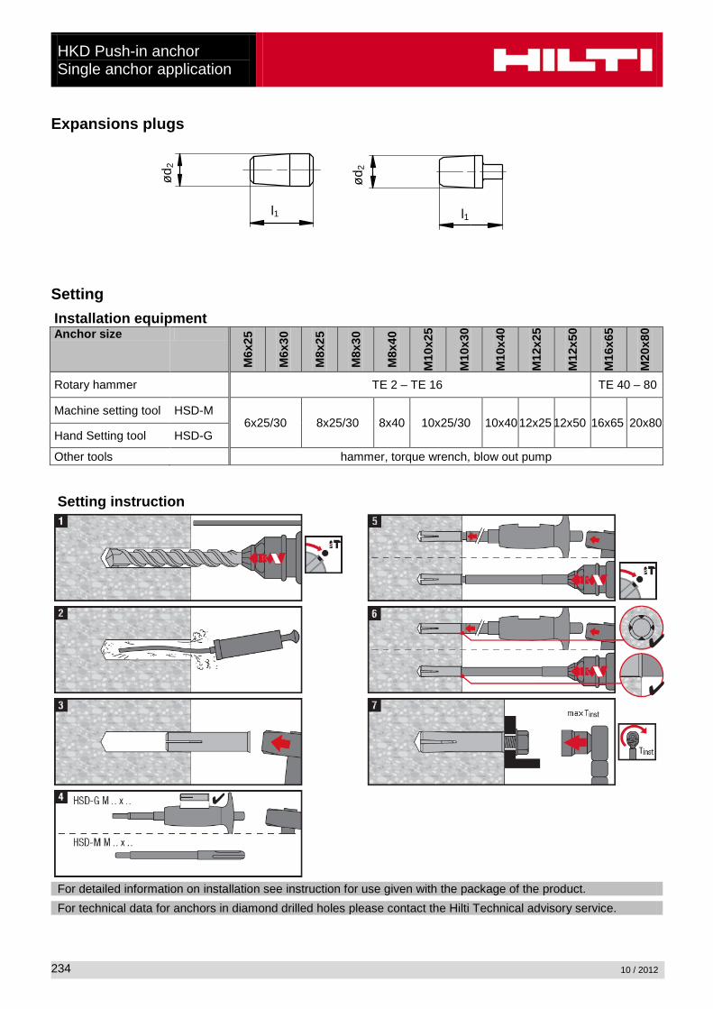
Expansions plugs
ød
2
l1
ød2
l1
Setting Installation equipment Anchor size
M6x
25
M6x
30
M8x
25
M8x
30
M8x
40
M10
x25
M10
x30
M10
x40
M12
x25
M12
x50
M16
x65
M20
x80
Rotary hammer TE 2 – TE 16 TE 40 – 80
Machine setting tool HSD-M 6x25/30 8x25/30 8x40 10x25/30 10x40 12x25 12x50 16x65 20x80
Hand Setting tool HSD-G
Other tools hammer, torque wrench, blow out pump Setting instruction
For detailed information on installation see instruction for use given with the package of the product.
For technical data for anchors in diamond drilled holes please contact the Hilti Technical advisory service.
HKD Push-in anchor
Single anchor application
10 / 2012
235
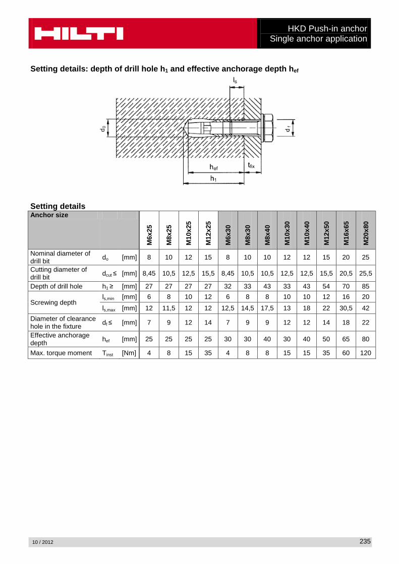
Setting details: depth of drill hole h1 and effective anchorage depth hef
Setting details Anchor size
M6x
25
M8x
25
M10
x25
M12
x25
M6x
30
M8x
30
M8x
40
M10
x30
M10
x40
M12
x50
M16
x65
M20
x80
Nominal diameter of drill bit do [mm] 8 10 12 15 8 10 10 12 12 15 20 25
Cutting diameter of drill bit dcut ≤ [mm] 8,45 10,5 12,5 15,5 8,45 10,5 10,5 12,5 12,5 15,5 20,5 25,5
Depth of drill hole h1 ≥ [mm] 27 27 27 27 32 33 43 33 43 54 70 85
Screwing depth ls,min [mm] 6 8 10 12 6 8 8 10 10 12 16 20
ls,max [mm] 12 11,5 12 12 12,5 14,5 17,5 13 18 22 30,5 42 Diameter of clearance hole in the fixture df ≤ [mm] 7 9 12 14 7 9 9 12 12 14 18 22
Effective anchorage depth hef [mm] 25 25 25 25 30 30 40 30 40 50 65 80
Max. torque moment Tinst [Nm] 4 8 15 35 4 8 8 15 15 35 60 120
HKD Push-in anchor Single anchor application
10 / 2012
236
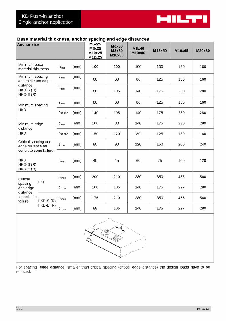
Base material thickness, anchor spacing and edge distances Anchor size M6x25
M8x25 M10x25 M12x25
M6x30 M8x30 M10x30
M8x40 M10x40 M12x50 M16x65 M20x80
Minimum base material thickness hmin [mm] 100 100 100 100 130 160
Minimum spacing and minimum edge distance HKD-S (R) HKD-E (R)
smin [mm] 60 60 80 125 130 160
cmin [mm] 88 105 140 175 230 280
Minimum spacing HKD
smin [mm] 80 60 80 125 130 160
for c≥ [mm] 140 105 140 175 230 280
Minimum edge distance HKD
cmin [mm] 100 80 140 175 230 280
for s≥ [mm] 150 120 80 125 130 160
Critical spacing and edge distance for concrete cone failure HKD HKD-S (R) HKD-E (R)
scr,N [mm] 80 90 120 150 200 240
ccr,N [mm] 40 45 60 75 100 120
Critical spacing and edge distance for splitting failure
HKD scr,sp [mm] 200 210 280 350 455 560
ccr,sp [mm] 100 105 140 175 227 280
HKD-S (R) HKD-E (R)
scr,sp [mm] 176 210 280 350 455 560
ccr,sp [mm] 88 105 140 175 227 280
For spacing (edge distance) smaller than critical spacing (critical edge distance) the design loads have to be reduced.
HKD Push-in anchor
Single anchor application
10 / 2012
237
Simplified design method Simplified version of the design method according ETAG 001, Annex C. Design resistance according data given in ETA-02/0032, issue 2010-04-22 . Influence of concrete strength Influence of edge distance Influence of spacing Valid for a group of two anchors. (The method may also be applied for anchor groups with more than two
anchors or more than one edge. The influencing factors must then be considered for each edge distance and spacing. The calculated design loads are then on the save side: They will be lower than the exact values according ETAG 001, Annex C. To avoid this, it is recommended to use the anchor design software PROFIS anchor)
The design method is based on the following simplification: No different loads are acting on individual anchors (no eccentricity)
The values are valid for one anchor. For more complex fastening applications please use the anchor design software PROFIS Anchor.
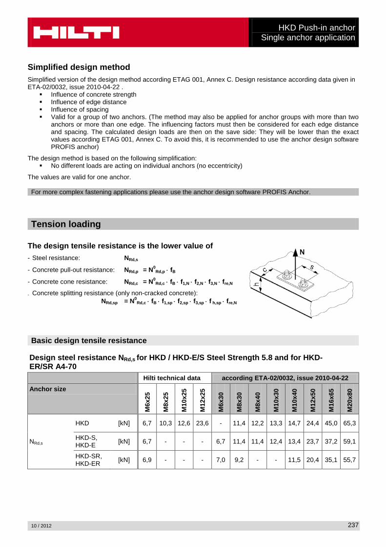
Tension loading
The design tensile resistance is the lower value of - Steel resistance: NRd,s
- Concrete pull-out resistance: NRd,p = N0Rd,p ⋅ fB
- Concrete cone resistance: NRd,c = N0Rd,c ⋅ fB ⋅ f1,N ⋅ f2,N ⋅ f3,N ⋅ fre,N
- Concrete splitting resistance (only non-cracked concrete): NRd,sp = N0
Rd,c ⋅ fB ⋅ f1,sp ⋅ f2,sp ⋅ f3,sp ⋅ f h,sp ⋅ fre,N
Basic design tensile resistance
Design steel resistance NRd,s for HKD / HKD-E/S Steel Strength 5.8 and for HKD-ER/SR A4-70 Hilti technical data according ETA-02/0032, issue 2010-04-22 Anchor size
M6x
25
M8x
25
M10
x25
M12
x25
M6x
30
M8x
30
M8x
40
M10
x30
M10
x40
M12
x50
M16
x65
M20
x80
HKD [kN] 6,7 10,3 12,6 23,6 - 11,4 12,2 13,3 14,7 24,4 45,0 65,3
NRd,s HKD-S, HKD-E [kN] 6,7 - - - 6,7 11,4 11,4 12,4 13,4 23,7 37,2 59,1
HKD-SR, HKD-ER [kN] 6,9 - - - 7,0 9,2 - - 11,5 20,4 35,1 55,7
HKD Push-in anchor Single anchor application
10 / 2012
238
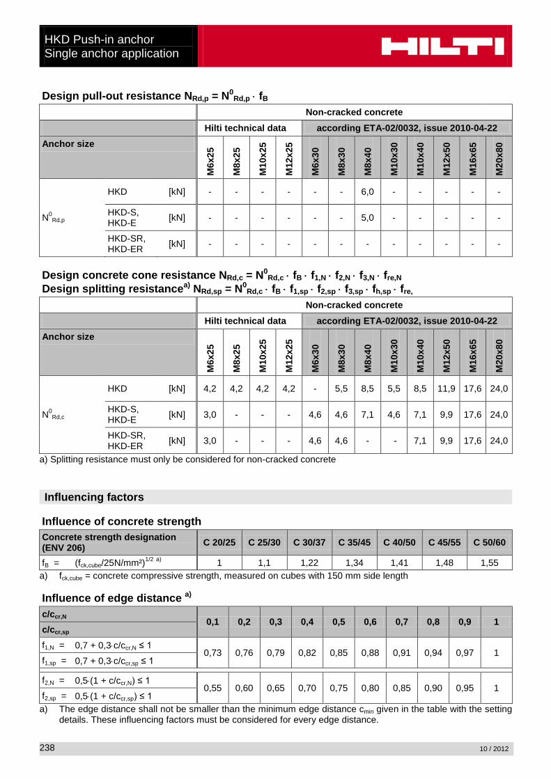
Design pull-out resistance NRd,p = N0Rd,p ⋅ fB
Non-cracked concrete Hilti technical data according ETA-02/0032, issue 2010-04-22 Anchor size
M6x
25
M8x
25
M10
x25
M12
x25
M6x
30
M8x
30
M8x
40
M10
x30
M10
x40
M12
x50
M16
x65
M20
x80
HKD [kN] - - - - - - 6,0 - - - - -
N0Rd,p HKD-S,
HKD-E [kN] - - - - - - 5,0 - - - - -
HKD-SR, HKD-ER [kN] - - - - - - - - - - - -
Design concrete cone resistance NRd,c = N0
Rd,c ⋅ fB ⋅ f1,N ⋅ f2,N ⋅ f3,N ⋅ fre,N Design splitting resistancea) NRd,sp = N0
Rd,c ⋅ fB ⋅ f1,sp ⋅ f2,sp ⋅ f3,sp ⋅ fh,sp ⋅ fre, Non-cracked concrete Hilti technical data according ETA-02/0032, issue 2010-04-22 Anchor size
M6x
25
M8x
25
M10
x25
M12
x25
M6x
30
M8x
30
M8x
40
M10
x30
M10
x40
M12
x50
M16
x65
M20
x80
HKD [kN] 4,2 4,2 4,2 4,2 - 5,5 8,5 5,5 8,5 11,9 17,6 24,0
N0Rd,c HKD-S,
HKD-E [kN] 3,0 - - - 4,6 4,6 7,1 4,6 7,1 9,9 17,6 24,0
HKD-SR, HKD-ER [kN] 3,0 - - - 4,6 4,6 - - 7,1 9,9 17,6 24,0
a) Splitting resistance must only be considered for non-cracked concrete Influencing factors
Influence of concrete strength
Concrete strength designation (ENV 206) C 20/25 C 25/30 C 30/37 C 35/45 C 40/50 C 45/55 C 50/60
fB = (fck,cube/25N/mm²)1/2 a) 1 1,1 1,22 1,34 1,41 1,48 1,55 a) fck,cube = concrete compressive strength, measured on cubes with 150 mm side length Influence of edge distance a)
c/ccr,N 0,1 0,2 0,3 0,4 0,5 0,6 0,7 0,8 0,9 1
c/ccr,sp f1,N = 0,7 + 0,3⋅c/ccr,N ≤ 1
0,73 0,76 0,79 0,82 0,85 0,88 0,91 0,94 0,97 1 f1,sp = 0,7 + 0,3⋅c/ccr,sp ≤ 1
f2,N = 0,5⋅(1 + c/ccr,N) ≤ 1
0,55 0,60 0,65 0,70 0,75 0,80 0,85 0,90 0,95 1 f2,sp = 0,5⋅(1 + c/ccr,sp) ≤ 1 a) The edge distance shall not be smaller than the minimum edge distance cmin given in the table with the setting
details. These influencing factors must be considered for every edge distance.
HKD Push-in anchor
Single anchor application
10 / 2012
239
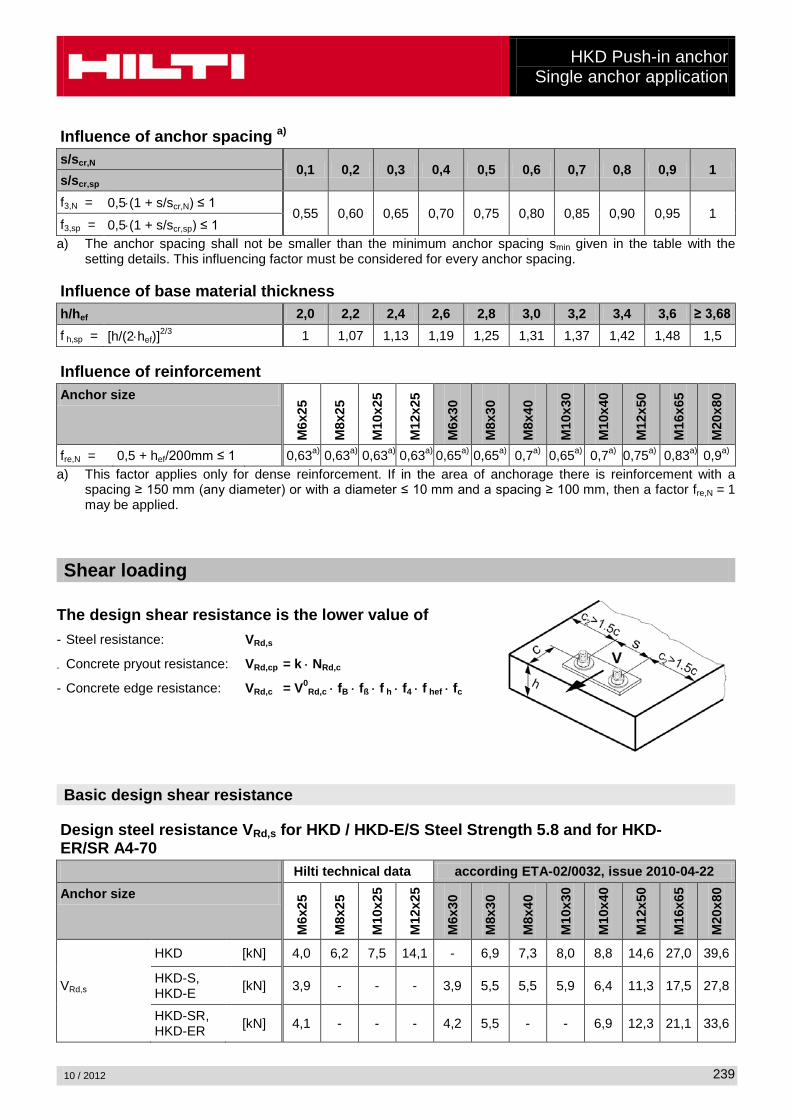
Influence of anchor spacing a)
s/scr,N 0,1 0,2 0,3 0,4 0,5 0,6 0,7 0,8 0,9 1
s/scr,sp f3,N = 0,5⋅(1 + s/scr,N) ≤ 1
0,55 0,60 0,65 0,70 0,75 0,80 0,85 0,90 0,95 1 f3,sp = 0,5⋅(1 + s/scr,sp) ≤ 1 a) The anchor spacing shall not be smaller than the minimum anchor spacing smin given in the table with the
setting details. This influencing factor must be considered for every anchor spacing. Influence of base material thickness
h/hef 2,0 2,2 2,4 2,6 2,8 3,0 3,2 3,4 3,6 ≥ 3,68 f h,sp = [h/(2⋅hef)]2/3 1 1,07 1,13 1,19 1,25 1,31 1,37 1,42 1,48 1,5 Influence of reinforcement Anchor size
M6x
25
M8x
25
M10
x25
M12
x25
M6x
30
M8x
30
M8x
40
M10
x30
M10
x40
M12
x50
M16
x65
M20
x80
fre,N = 0,5 + hef/200mm ≤ 1 0,63a) 0,63a) 0,63a) 0,63a) 0,65a) 0,65a) 0,7a) 0,65a) 0,7a) 0,75a) 0,83a) 0,9a) a) This factor applies only for dense reinforcement. If in the area of anchorage there is reinforcement with a
spacing ≥ 150 mm (any diameter) or with a diameter ≤ 10 mm and a spacing ≥ 100 mm, then a factor fre,N = 1 may be applied.
Shear loading
The design shear resistance is the lower value of - Steel resistance: VRd,s
- Concrete pryout resistance: VRd,cp = k ⋅ NRd,c
- Concrete edge resistance: VRd,c = V0Rd,c ⋅ fB ⋅ fß ⋅ f h ⋅ f4 ⋅ f hef ⋅ fc
Basic design shear resistance
Design steel resistance VRd,s for HKD / HKD-E/S Steel Strength 5.8 and for HKD-ER/SR A4-70 Hilti technical data according ETA-02/0032, issue 2010-04-22 Anchor size
M6x
25
M8x
25
M10
x25
M12
x25
M6x
30
M8x
30
M8x
40
M10
x30
M10
x40
M12
x50
M16
x65
M20
x80
HKD [kN] 4,0 6,2 7,5 14,1 - 6,9 7,3 8,0 8,8 14,6 27,0 39,6
VRd,s HKD-S, HKD-E [kN] 3,9 - - - 3,9 5,5 5,5 5,9 6,4 11,3 17,5 27,8
HKD-SR, HKD-ER [kN] 4,1 - - - 4,2 5,5 - - 6,9 12,3 21,1 33,6
HKD Push-in anchor Single anchor application
10 / 2012
240
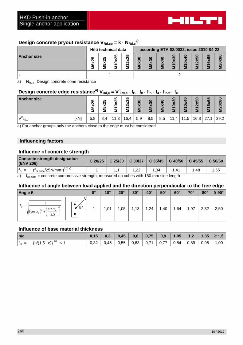
Design concrete pryout resistance VRd,cp = k ⋅ NRd,ca)
Hilti technical data according ETA-02/0032, issue 2010-04-22 Anchor size
M6x
25
M8x
25
M10
x25
M12
x25
M6x
30
M8x
30
M8x
40
M10
x30
M10
x40
M12
x50
M16
x65
M20
x80
k 1 2 a) NRd,c: Design concrete cone resistance Design concrete edge resistancea) VRd,c = V0
Rd,c ⋅ fB ⋅ fß ⋅ f h ⋅ f4 ⋅ f hef ⋅ fc Anchor size
M6x
25
M8x
25
M10
x25
M12
x25
M6x
30
M8x
30
M8x
40
M10
x30
M10
x40
M12
x50
M16
x65
M20
x80
V0Rd,c [kN] 5,8 8,4 11,3 16,4 5,9 8,5 8,5 11,4 11,5 16,8 27,1 39,2
a) For anchor groups only the anchors close to the edge must be considered Influencing factors
Influence of concrete strength
Concrete strength designation (ENV 206) C 20/25 C 25/30 C 30/37 C 35/45 C 40/50 C 45/55 C 50/60
fB = (fck,cube/25N/mm²)1/2 a) 1 1,1 1,22 1,34 1,41 1,48 1,55 a) fck,cube = concrete compressive strength, measured on cubes with 150 mm side length Influence of angle between load applied and the direction perpendicular to the free edge
Angle ß 0° 10° 20° 30° 40° 50° 60° 70° 80° ≥ 90°
( )2
2
5,2sincos
1
+
=V
V
fα
αβ
1 1,01 1,05 1,13 1,24 1,40 1,64 1,97 2,32 2,50
Influence of base material thickness
h/c 0,15 0,3 0,45 0,6 0,75 0,9 1,05 1,2 1,35 ≥ 1,5 f h = {h/(1,5 ⋅ c)} 1/2 ≤ 1 0,32 0,45 0,55 0,63 0,71 0,77 0,84 0,89 0,95 1,00
HKD Push-in anchor
Single anchor application
10 / 2012
241
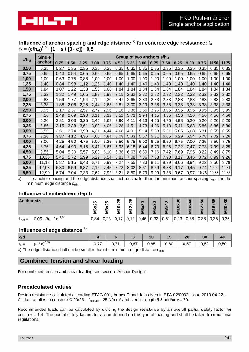
Influence of anchor spacing and edge distance a) for concrete edge resistance: f4 f4 = (c/hef)1,5 ⋅ (1 + s / [3 ⋅ c]) ⋅ 0,5
c/hef Single anchor
Group of two anchors s/hef 0.75 1.50 2.25 3.00 3.75 4.50 5.25 6.00 6.75 7.50 8.25 9.00 9.75 10.50 11.25
0,50 0,35 0,27 0,35 0,35 0,35 0,35 0,35 0,35 0,35 0,35 0,35 0,35 0,35 0,35 0,35 0,35 0,75 0,65 0,43 0,54 0,65 0,65 0,65 0,65 0,65 0,65 0,65 0,65 0,65 0,65 0,65 0,65 0,65 1,00 1,00 0,63 0,75 0,88 1,00 1,00 1,00 1,00 1,00 1,00 1,00 1,00 1,00 1,00 1,00 1,00 1,25 1,40 0,84 0,98 1,12 1,26 1,40 1,40 1,40 1,40 1,40 1,40 1,40 1,40 1,40 1,40 1,40 1,50 1,84 1,07 1,22 1,38 1,53 1,68 1,84 1,84 1,84 1,84 1,84 1,84 1,84 1,84 1,84 1,84 1,75 2,32 1,32 1,49 1,65 1,82 1,98 2,15 2,32 2,32 2,32 2,32 2,32 2,32 2,32 2,32 2,32 2,00 2,83 1,59 1,77 1,94 2,12 2,30 2,47 2,65 2,83 2,83 2,83 2,83 2,83 2,83 2,83 2,83 2,25 3,38 1,88 2,06 2,25 2,44 2,63 2,81 3,00 3,19 3,38 3,38 3,38 3,38 3,38 3,38 3,38 2,50 3,95 2,17 2,37 2,57 2,77 2,96 3,16 3,36 3,56 3,76 3,95 3,95 3,95 3,95 3,95 3,95 2,75 4,56 2,49 2,69 2,90 3,11 3,32 3,52 3,73 3,94 4,15 4,35 4,56 4,56 4,56 4,56 4,56 3,00 5,20 2,81 3,03 3,25 3,46 3,68 3,90 4,11 4,33 4,55 4,76 4,98 5,20 5,20 5,20 5,20 3,25 5,86 3,15 3,38 3,61 3,83 4,06 4,28 4,51 4,73 4,96 5,18 5,41 5,63 5,86 5,86 5,86 3,50 6,55 3,51 3,74 3,98 4,21 4,44 4,68 4,91 5,14 5,38 5,61 5,85 6,08 6,31 6,55 6,55 3,75 7,26 3,87 4,12 4,36 4,60 4,84 5,08 5,33 5,57 5,81 6,05 6,29 6,54 6,78 7,02 7,26 4,00 8,00 4,25 4,50 4,75 5,00 5,25 5,50 5,75 6,00 6,25 6,50 6,75 7,00 7,25 7,50 7,75 4,25 8,76 4,64 4,90 5,15 5,41 5,67 5,93 6,18 6,44 6,70 6,96 7,22 7,47 7,73 7,99 8,25 4,50 9,55 5,04 5,30 5,57 5,83 6,10 6,36 6,63 6,89 7,16 7,42 7,69 7,95 8,22 8,49 8,75 4,75 10,35 5,45 5,72 5,99 6,27 6,54 6,81 7,08 7,36 7,63 7,90 8,17 8,45 8,72 8,99 9,26 5,00 11,18 5,87 6,15 6,43 6,71 6,99 7,27 7,55 7,83 8,11 8,39 8,66 8,94 9,22 9,50 9,78 5,25 12,03 6,30 6,59 6,87 7,16 7,45 7,73 8,02 8,31 8,59 8,88 9,17 9,45 9,74 10,02 10,31 5,50 12,90 6,74 7,04 7,33 7,62 7,92 8,21 8,50 8,79 9,09 9,38 9,67 9,97 10,26 10,55 10,85
a) The anchor spacing and the edge distance shall not be smaller than the minimum anchor spacing smin and the minimum edge distance cmin.
Influence of embedment depth
Anchor size
M6x
25
M8x
25
M10
x25
M12
x25
M6x
30
M8x
30
M8x
40
M10
x30
M10
x40
M12
x50
M16
x65
M20
x80
f hef = 0,05 ⋅ (hef / d)1,68 0,34 0,23 0,17 0,12 0,46 0,32 0,51 0,23 0,38 0,38 0,36 0,35 Influence of edge distance a)
c/d 4 6 8 10 15 20 30 40 fc = (d / c)0,19 0,77 0,71 0,67 0,65 0,60 0,57 0,52 0,50 a) The edge distance shall not be smaller than the minimum edge distance cmin. Combined tension and shear loading
For combined tension and shear loading see section “Anchor Design”. Precalculated values Design resistance calculated according ETAG 001, Annex C and data given in ETA-02/0032, issue 2010-04-22 . All data applies to concrete C 20/25 – fck,cube =25 N/mm² and steel strength 5.8 and/or A4-70. Recommended loads can be calculated by dividing the design resistance by an overall partial safety factor for action γ = 1,4. The partial safety factors for action depend on the type of loading and shall be taken from national regulations.
HKD Push-in anchor Single anchor application
10 / 2012
242
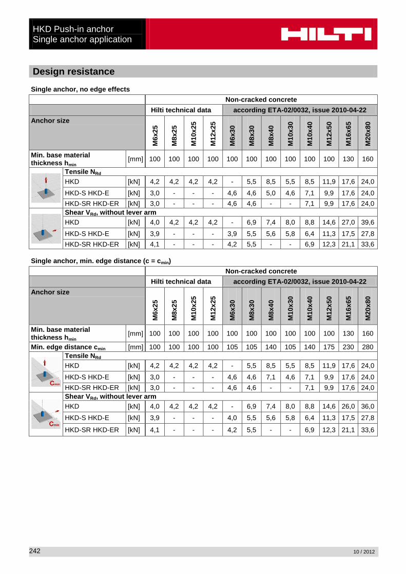
Design resistance Single anchor, no edge effects Non-cracked concrete Hilti technical data according ETA-02/0032, issue 2010-04-22 Anchor size
M6x
25
M8x
25
M10
x25
M12
x25
M6x
30
M8x
30
M8x
40
M10
x30
M10
x40
M12
x50
M16
x65
M20
x80
Min. base material thickness hmin [mm] 100 100 100 100 100 100 100 100 100 100 130 160
Tensile NRd HKD [kN] 4,2 4,2 4,2 4,2 - 5,5 8,5 5,5 8,5 11,9 17,6 24,0
HKD-S HKD-E [kN] 3,0 - - - 4,6 4,6 5,0 4,6 7,1 9,9 17,6 24,0 HKD-SR HKD-ER [kN] 3,0 - - - 4,6 4,6 - - 7,1 9,9 17,6 24,0
Shear VRd, without lever arm HKD [kN] 4,0 4,2 4,2 4,2 - 6,9 7,4 8,0 8,8 14,6 27,0 39,6
HKD-S HKD-E [kN] 3,9 - - - 3,9 5,5 5,6 5,8 6,4 11,3 17,5 27,8 HKD-SR HKD-ER [kN] 4,1 - - - 4,2 5,5 - - 6,9 12,3 21,1 33,6
Single anchor, min. edge distance (c = cmin) Non-cracked concrete Hilti technical data according ETA-02/0032, issue 2010-04-22 Anchor size
M6x
25
M8x
25
M10
x25
M12
x25
M6x
30
M8x
30
M8x
40
M10
x30
M10
x40
M12
x50
M16
x65
M20
x80
Min. base material thickness hmin [mm] 100 100 100 100 100 100 100 100 100 100 130 160
Min. edge distance cmin [mm] 100 100 100 100 105 105 140 105 140 175 230 280
Tensile NRd HKD [kN] 4,2 4,2 4,2 4,2 - 5,5 8,5 5,5 8,5 11,9 17,6 24,0
HKD-S HKD-E [kN] 3,0 - - - 4,6 4,6 7,1 4,6 7,1 9,9 17,6 24,0 HKD-SR HKD-ER [kN] 3,0 - - - 4,6 4,6 - - 7,1 9,9 17,6 24,0
Shear VRd, without lever arm HKD [kN] 4,0 4,2 4,2 4,2 - 6,9 7,4 8,0 8,8 14,6 26,0 36,0
HKD-S HKD-E [kN] 3,9 - - - 4,0 5,5 5,6 5,8 6,4 11,3 17,5 27,8
HKD-SR HKD-ER [kN] 4,1 - - - 4,2 5,5 - - 6,9 12,3 21,1 33,6
HKD Push-in anchor
Single anchor application
10 / 2012
243
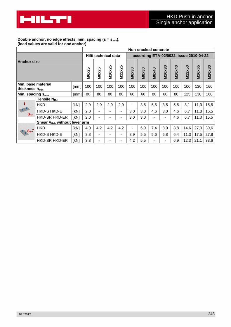
Double anchor, no edge effects, min. spacing (s = smin), (load values are valid for one anchor) Non-cracked concrete Hilti technical data according ETA-02/0032, issue 2010-04-22 Anchor size
M6x
25
M8x
25
M10
x25
M12
x25
M6x
30
M8x
30
M8x
40
M10
x30
M10
x40
M12
x50
M16
x65
M20
x80
Min. base material thickness hmin [mm] 100 100 100 100 100 100 100 100 100 100 130 160
Min. spacing smin [mm] 80 80 80 80 60 60 80 60 80 125 130 160
Tensile NRd HKD [kN] 2,9 2,9 2,9 2,9 - 3,5 5,5 3,5 5,5 8,1 11,3 15,5
HKD-S HKD-E [kN] 2,0 - - - 3,0 3,0 4,6 3,0 4,6 6,7 11,3 15,5 HKD-SR HKD-ER [kN] 2,0 - - - 3,0 3,0 - - 4,6 6,7 11,3 15,5
Shear VRd, without lever arm HKD [kN] 4,0 4,2 4,2 4,2 - 6,9 7,4 8,0 8,8 14,6 27,0 39,6
HKD-S HKD-E [kN] 3,8 - - - 3,9 5,5 5,6 5,8 6,4 11,3 17,5 27,8 HKD-SR HKD-ER [kN] 3,8 - - - 4,2 5,5 - - 6,9 12,3 21,1 33,6
HKD Push-in anchor Redundant fastening
10 / 2012
244
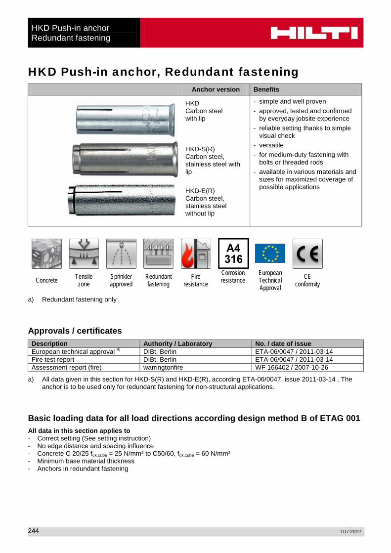
HKD Push-in anchor, Redundant fastening Anchor version Benefits
HKD Carbon steel with lip
HKD-S(R) Carbon steel, stainless steel with lip
HKD-E(R) Carbon steel, stainless steel without lip
- simple and well proven - approved, tested and confirmed
by everyday jobsite experience - reliable setting thanks to simple
visual check - versatile - for medium-duty fastening with
bolts or threaded rods - available in various materials and
sizes for maximized coverage of possible applications
Concrete Tensile zone
Sprinkler approved
Redundant fastening
Fire resistance
Corrosion resistance
European Technical Approval
CE conformity
a) Redundant fastening only Approvals / certificates Description Authority / Laboratory No. / date of issue European technical approval a) DIBt, Berlin ETA-06/0047 / 2011-03-14 Fire test report DIBt, Berlin ETA-06/0047 / 2011-03-14 Assessment report (fire) warringtonfire WF 166402 / 2007-10-26
a) All data given in this section for HKD-S(R) and HKD-E(R), according ETA-06/0047, issue 2011-03-14 . The anchor is to be used only for redundant fastening for non-structural applications.
Basic loading data for all load directions according design method B of ETAG 001 All data in this section applies to - Correct setting (See setting instruction) - No edge distance and spacing influence - Concrete C 20/25 fck,cube = 25 N/mm² to C50/60, fck,cube = 60 N/mm² - Minimum base material thickness - Anchors in redundant fastening
HKD Push-in anchor Redundant fastening
10 / 2012
245
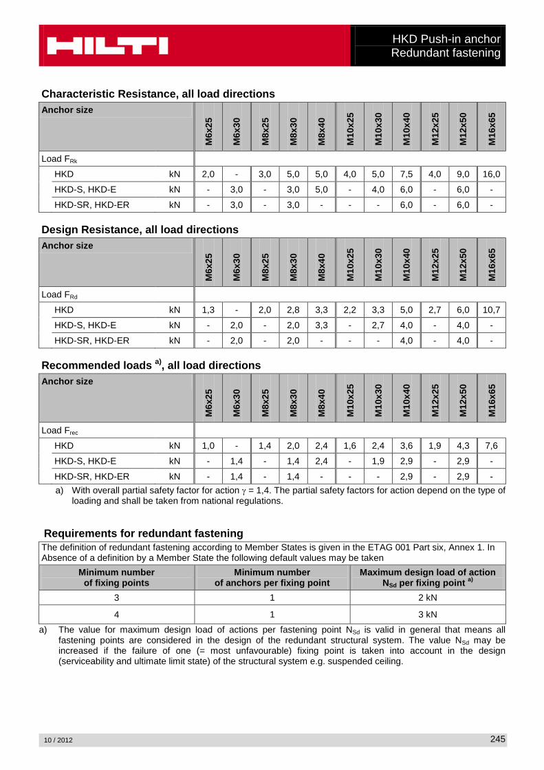
Characteristic Resistance, all load directions Anchor size
M6x
25
M6x
30
M8x
25
M8x
30
M8x
40
M10
x25
M10
x30
M10
x40
M12
x25
M12
x50
M16
x65
Load FRk HKD kN 2,0 - 3,0 5,0 5,0 4,0 5,0 7,5 4,0 9,0 16,0
HKD-S, HKD-E kN - 3,0 - 3,0 5,0 - 4,0 6,0 - 6,0 -
HKD-SR, HKD-ER kN - 3,0 - 3,0 - - - 6,0 - 6,0 - Design Resistance, all load directions Anchor size
M6x
25
M6x
30
M8x
25
M8x
30
M8x
40
M10
x25
M10
x30
M10
x40
M12
x25
M12
x50
M16
x65
Load FRd HKD kN 1,3 - 2,0 2,8 3,3 2,2 3,3 5,0 2,7 6,0 10,7
HKD-S, HKD-E kN - 2,0 - 2,0 3,3 - 2,7 4,0 - 4,0 -
HKD-SR, HKD-ER kN - 2,0 - 2,0 - - - 4,0 - 4,0 - Recommended loads a), all load directions Anchor size
M6x
25
M6x
30
M8x
25
M8x
30
M8x
40
M10
x25
M10
x30
M10
x40
M12
x25
M12
x50
M16
x65
Load Frec HKD kN 1,0 - 1,4 2,0 2,4 1,6 2,4 3,6 1,9 4,3 7,6
HKD-S, HKD-E kN - 1,4 - 1,4 2,4 - 1,9 2,9 - 2,9 -
HKD-SR, HKD-ER kN - 1,4 - 1,4 - - - 2,9 - 2,9 - a) With overall partial safety factor for action γ = 1,4. The partial safety factors for action depend on the type of
loading and shall be taken from national regulations.
Requirements for redundant fastening The definition of redundant fastening according to Member States is given in the ETAG 001 Part six, Annex 1. In Absence of a definition by a Member State the following default values may be taken
Minimum number of fixing points
Minimum number of anchors per fixing point
Maximum design load of action NSd per fixing point a)
3 1 2 kN
4 1 3 kN a) The value for maximum design load of actions per fastening point NSd is valid in general that means all
fastening points are considered in the design of the redundant structural system. The value NSd may be increased if the failure of one (= most unfavourable) fixing point is taken into account in the design (serviceability and ultimate limit state) of the structural system e.g. suspended ceiling.
HKD Push-in anchor Redundant fastening
10 / 2012
246
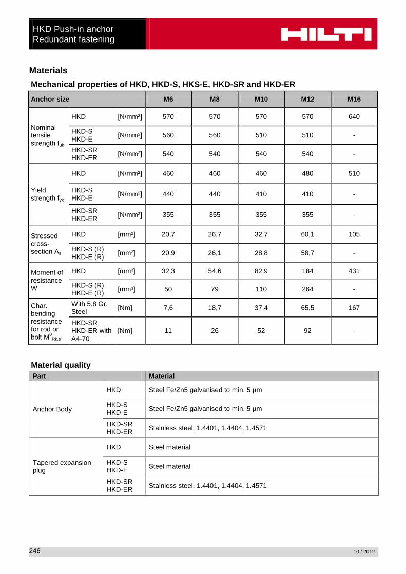
Materials Mechanical properties of HKD, HKD-S, HKS-E, HKD-SR and HKD-ER
Anchor size M6 M8 M10 M12 M16
Nominal tensile strength fuk
HKD [N/mm²] 570 570 570 570 640
HKD-S HKD-E [N/mm²] 560 560 510 510 -
HKD-SR HKD-ER [N/mm²] 540 540 540 540 -
Yield strength fyk
HKD [N/mm²] 460 460 460 480 510
HKD-S HKD-E [N/mm²] 440 440 410 410 -
HKD-SR HKD-ER [N/mm²] 355 355 355 355 -
Stressed cross-section As
HKD [mm²] 20,7 26,7 32,7 60,1 105
HKD-S (R) HKD-E (R) [mm²] 20,9 26,1 28,8 58,7 -
Moment of resistance W
HKD [mm³] 32,3 54,6 82,9 184 431
HKD-S (R) HKD-E (R) [mm³] 50 79 110 264 -
Char. bending resistance for rod or bolt M0
Rk,s
With 5.8 Gr. Steel [Nm] 7,6 18,7 37,4 65,5 167
HKD-SR HKD-ER with A4-70
[Nm] 11 26 52 92 -
Material quality Part Material
Anchor Body
HKD Steel Fe/Zn5 galvanised to min. 5 µm
HKD-S HKD-E Steel Fe/Zn5 galvanised to min. 5 µm
HKD-SR HKD-ER Stainless steel, 1.4401, 1.4404, 1.4571
Tapered expansion plug
HKD Steel material
HKD-S HKD-E Steel material
HKD-SR HKD-ER Stainless steel, 1.4401, 1.4404, 1.4571
HKD Push-in anchor Redundant fastening
10 / 2012
247
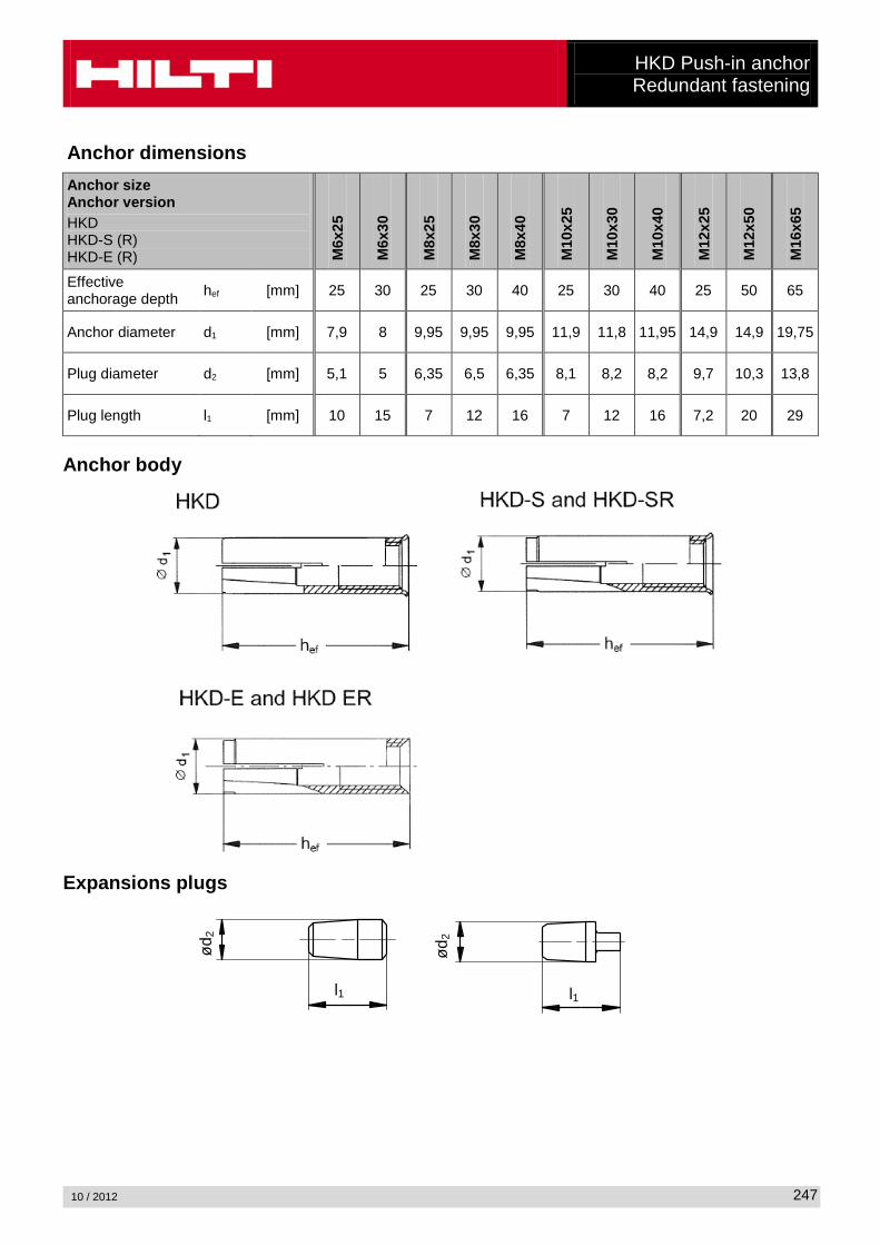
Anchor dimensions Anchor size Anchor version HKD HKD-S (R) HKD-E (R) M
6x25
M6x
30
M8x
25
M8x
30
M8x
40
M10
x25
M10
x30
M10
x40
M12
x25
M12
x50
M16
x65
Effective anchorage depth hef [mm] 25 30 25 30 40 25 30 40 25 50 65
Anchor diameter d1 [mm] 7,9 8 9,95 9,95 9,95 11,9 11,8 11,95 14,9 14,9 19,75
Plug diameter d2 [mm] 5,1 5 6,35 6,5 6,35 8,1 8,2 8,2 9,7 10,3 13,8
Plug length l1 [mm] 10 15 7 12 16 7 12 16 7,2 20 29
Anchor body
Expansions plugs
ød2
l1
ød2
l1
HKD Push-in anchor Redundant fastening
10 / 2012
248
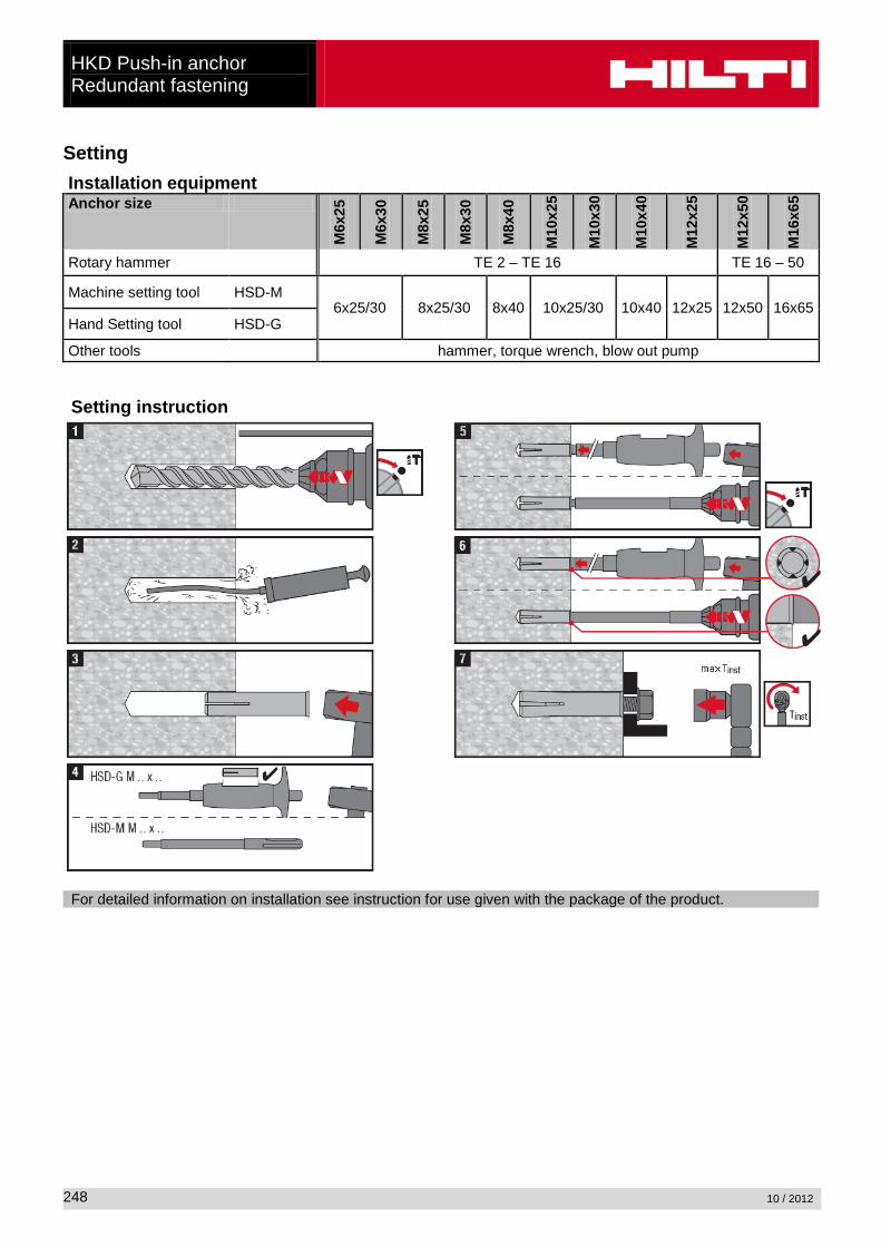
Setting Installation equipment Anchor size
M6x
25
M6x
30
M8x
25
M8x
30
M8x
40
M10
x25
M10
x30
M10
x40
M12
x25
M12
x50
M16
x65
Rotary hammer TE 2 – TE 16 TE 16 – 50
Machine setting tool HSD-M 6x25/30 8x25/30 8x40 10x25/30 10x40 12x25 12x50 16x65
Hand Setting tool HSD-G
Other tools hammer, torque wrench, blow out pump Setting instruction
For detailed information on installation see instruction for use given with the package of the product.

HKD Push-in anchor Redundant fastening
10 / 2012
249
Setting details: depth of drill hole h1 and effective anchorage depth hef
Setting details Anchor size
M6x
25
M6x
30
M8x
25
M8x
30
M8x
40
M10
x25
M10
x30
M10
x40
M12
x25
M12
x50
M16
x65
Nominal diameter of drill bit do [mm] 8 8 10 10 10 12 12 12 15 15 20
Cutting diameter of drill bit dcut ≤ [mm] 8,45 8,45 10,5 10,5 10,5 12,5 12,5 12,5 15,5 15,5 20,5
Depth of drill hole h1 ≥ [mm] 27 32 27 33 43 27 33 43 27 54 70
Screwing depth ls,min [mm] 6 6 8 8 8 10 10 10 12 12 16
ls,max [mm] 12 12,5 11,5 14,5 17,5 12 13 18 12 22 30,5 Diameter of clearance hole in the fixture df ≤ [mm] 7 7 9 9 9 12 12 12 14 14 18
Effective anchorage depth hef [mm] 25 30 25 30 40 25 30 40 25 50 65
Max. torque moment Tinst [Nm] 4 4 8 8 8 15 15 15 35 35 60
HKD Push-in anchor Redundant fastening
10 / 2012
250
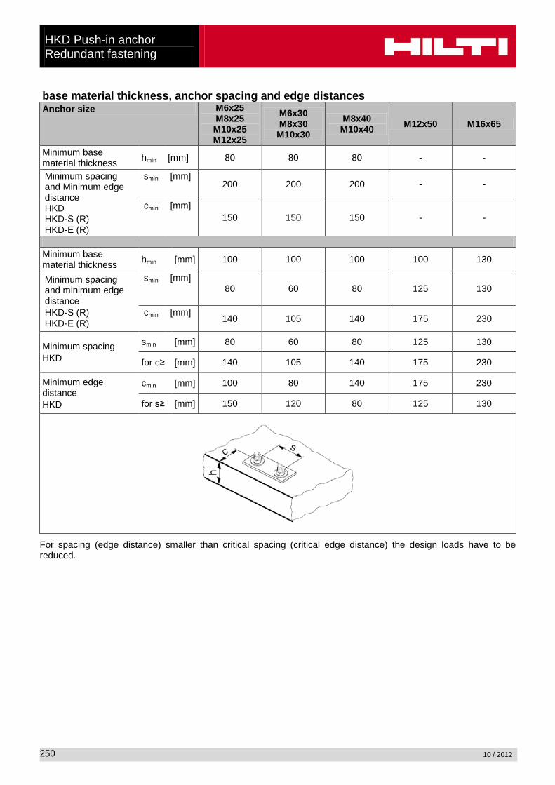
base material thickness, anchor spacing and edge distances Anchor size M6x25
M8x25 M10x25 M12x25
M6x30 M8x30 M10x30
M8x40 M10x40 M12x50 M16x65
Minimum base material thickness hmin [mm] 80 80 80 - -
Minimum spacing and Minimum edge distance HKD HKD-S (R) HKD-E (R)
smin [mm] 200 200 200 - -
cmin [mm] 150 150 150 - -
Minimum base material thickness hmin [mm] 100 100 100 100 130
Minimum spacing and minimum edge distance HKD-S (R) HKD-E (R)
smin [mm] 80 60 80 125 130
cmin [mm] 140 105 140 175 230
Minimum spacing HKD
smin [mm] 80 60 80 125 130
for c≥ [mm] 140 105 140 175 230
Minimum edge distance HKD
cmin [mm] 100 80 140 175 230
for s≥ [mm] 150 120 80 125 130
For spacing (edge distance) smaller than critical spacing (critical edge distance) the design loads have to be reduced.