hma fracture mechanics - petersen asphalt research conference
TRANSCRIPT

HMA Fracture Mechanics
Reynaldo (Rey) Roque, Ph.D,P.EDepartment of Civil and Coastal Engineering
University of Florida
Pavement Performance Prediction Symposium Laramie, Wyoming

University of Florida
Objectives• Define Fracture Mechanics and Illustrate Its
Importance• Illustrate How Fracture Mechanics Can Explain
Changes in Failure Mechanisms When Other Theories may not– Fracture mechanics is necessary
• Describe and Illustrate the Key Features of HMA Fracture Mechanics
• Illustrate How Fracture Mechanics Can Help to Optimize Mixture and Pavement System Design
• Briefly Discuss Emerging Tools for Fracture Simulation in Pavements

University of Florida
• A Theory That Predicts the Effects of Cracks in Materials
• Importance– Cracks intensify stresses
• Distinct from and greater than stress concentrations
– Stress intensities accelerate distress and can dictate failure mechanism
– Characteristics and distribution of cracks affect mixture fracture resistance
Fracture Mechanics

University of Florida
• Identify/Design Pavement Systems to:– Resist crack initiation– Stop or minimize propagation
• Establish Guidelines for Mixtures that Resist Initiation and Propagation
• Identify Effective and Simple Test Methods and Parameters to Evaluate Fracture Resistance of Mixtures and Pavement Systems
Applications

University of Florida
• Fracture @ KIC (one-time event) • Controlled Crack Growth @ K< KIC
K = Stress Intensity Factor = f( σFA, geometry)
KI = Mode I Stress Intensity Factor ≅ σFA aπ
σFA
a
Mode I Mode II Mode III
Basic Theory

University of Florida
Hole/Void
Crack σmax = 3σ σmax = 3σ
K1 = σ aπ K2 = σ aπ2
K1 < K2
St1 = St2a
a
2a
2a
Crack
Hole
W
W
* For a<<W
Stress Intensity ≠ Stress Concentration

University of Florida
Elastic
Elastoplastic
Theory Depends on How Material Dissipates Stress (Energy) Near Crack Tip
ε
σ
σ
ε
Plastic Zone
Crack Tip
σyield
σyield
FM Is Material Dependent.

University of Florida
Traditional Fatigue
Continuum Damage
Fracture Mechanics
No Change • Reduced Modulus • Stress Concentration
••
Geometry ChangeStress Intensity
. . .
. . .. . .. . .
. . .
. . .
. . .
. . .. . .. . .
. . .
. . .
. . .
. . .. . .. . .
. . .
. . .
. . .
. . .. . .. . .
. . .
. . .
∞
0
Loads
. . .
. . .
. . .
. . .. .
.
Representing Cracking Mechanism

University of Florida
Traditional Fatigue & Variations• Cumulative Damage leads to fatigue failure
•
• State of material never changes; no effect on response of material or pavement (i.e. no localization)
• No fundamental description of damage or “failure”
n
f AN ⎟⎠⎞
⎜⎝⎛ε
=1

University of Florida
Traditional Fatigue & VariationsFailure when E < ½E0?
N-Load Repetitions
E
A B
• Matl A damages faster than Matl B (E reduced in less reps). Does Matl A fracture faster than Matl B?
• Tolerance is independent of rate of damage. Matl A might have a higher threshold than B.
Need to consider the concept of a threshold

University of Florida
Continuum Damage Mechanics
σFAσFA
σFA
• Cumulative Damage leads to failure• Micro-damage = Micro-cracks• No fundamental description of “failure”
– Failure = ½ E0
– No stress intensities
Reality
TheoryStress Concentration

University of Florida
σFAσFA
Fracture Mechanics
a
Crack length
σFA
Theory
∞
Reality
Critical Condition
(General) πaσ K
ModeTensionK
FAI
I
≅
≡
Critical Stress Intensity Factor
(Critical) πaσ K FA(C)I(C) ≅
• When σFA = σFA(C) Uncontrolled Cracking • When σFA < σFA(C) Controlled Crack Growth (crack will
not go through the entire cross-section)

University of Florida
Traditional Fracture Mechanics
Paris Law ( )nΔK AdNda
=
A, n – material constantsΔK – change in stress intensity
Basic Assumption:Each time we load the material, the crack propagates
• Micro-damage = Macro-damage = Cracking
• No distinction between micro- and macro-cracks
• Propagation only
Example: LEFM

University of Florida
• Damage = DCSE accumulation (Micro-cracks)• Fracture = Macro-crack initiation and growth
– Driven primarily by tension
• There is a threshold – separates damage from failure
• Not all damage is permanent– Damage is permanent only when the threshold is
exceeded– Damage below the threshold is healable
HMA Fracture Mechanics

University of Florida
• Calculates crack initiation and growth for a given level of applied stress
• Using:– Material properties
• m, D1 for DCSE accumulation (tensile creep test)• DCSEf and FE thresholds (tensile strength test)
– Structural model for stress distribution• FEM or BEM (more later)
HMA Fracture Model

University of Florida
MR
Stre
ss, σ
Strain, ε
DCSEf
x
Log
D(t
)
Log t1
D1
m
Material Properties
Fundamental properties control mixture damage and fracture
• m and D1 control DCSE (damage)
• DCSEf limit controls crack initiation/growth

University of Florida
Fracture Energy
MR
x
Stre
ss, σ
Strain, ε
St
(Strength)
εf
(Fracture)
St, Load @ failure
Deformation @ instant of fracture
Superpave Pill
DCSE
Based on the MR and Strength testsFracture Energy Failure Limits

University of Florida
DCS
E 1
DCSE 2
EE2
EE1
Fracture Energy Failure LimitsStrength (Fracture) Test
ε
σ
εfail1
St1
εfail2
St2
MR2
MR1
Fast Loading Rate
Slow Loading Rate
St1 > St2
εfail1 < εfail2
Low Damage prior to Fracture
High Damage prior to Fracture
However21 DCSEDCSE ≅
21 FEFE ≅

University of Florida
0.0
0.2
0.4
0.6
0.8
1.0
1.2
0.0
0.20.4
0.60.8
1.00.4
0.8
1.2
DC
SE
f fro
m C
reep
Tes
t
DCSEf from Fracture Test
DCSEf from Strength Test
• The threshold is fundamental – independent of mode of loading– Strength– Cyclic– Creep
The Threshold

University of Florida
Failure ThresholdThe material can fail in two ways:
• If the accumulated creep exceeds the DCSEf• If the accumulated creep plus the elastic exceeds the FE
*AccumulatedCreep Energy
Elastic Energy
Ener
gy, E
Cycles, NEn
ergy
, ECycles, N
FE
DCSEf
*
AccumulatedCreep Energy
Elastic Energy

University of Florida
Potential loading conditions in the fieldFailure Threshold
Ener
gy, E
FE
DCSEDamage Healing
Day 1 Day 2
Damage Healing

University of Florida
n
n-1
zone 1
zone 2
σFAσFA
Crack Initiation and Growth Model
σFA
DCSE accumulation in each Zone
3
σavg(i,j)
Where : i = zone #j = condition #
σavg(1,1)
σavg(n,1)
σavg(2,1)
Crack initiates when DCSE exceeds DCSE limit in zone 1

University of Florida
Crack Growth ModelCrack Propagation Begins
σFAσFA
σFA • Problem now changes from stress concentration to stress intensity
• Need new stress distribution
Limit max σ to tensile strengthStn
n-1
zone 23
σavg(n,2)
σavg(2,2)
σavg(3,2)
St
• The crack initiated through zone 1 • Stresses redistribute throughout the
remaining zones• Propagation continues only when
DCSE/FE limit is exceeded in zone 2

University of Florida
Crack Propagation (Paris Law)
Crac
k Le
ngth
, a
No. of Load Applications, N
nAdNda
ΔΚ×=
Threshold
Macro-crack initiationMicro-crackThreshold
Macro-crack(crack-growth)
Micro-crack(damage)
Crack propagation in Asphalt Pavements occurs in steps.
Crack Growth Model

University of Florida
0
10
20
30
40
50
0 1000 2000 3000 4000
Number of cycles, N
Crac
k Le
ngth
/2,
a (m
m) HMA Fracture Mechanics Model
Fracture Test
Crack Growth Model

University of Florida
21DCSE1
Decreasingm,D1
Nf1
fnc(m,D1,σave)DCS
E
N
DecreasingDCSEf
DCSE2A
DCSE2B
DCSE, m & D1 are interrelated
Main Idea:Can not improve performance by changing a single property.Have to consider the entire system.
Nf2ANf2B
Can go either way
HMA Fracture Model

University of Florida
• 25 field test sections to-date.– Continuing study w/ 12 additional planned
• Comprehensive evaluation:– Volumetric properties– Material properties– Effect of traffic loads and tires– Pavement structure (pavement design)
Field Study
University of Florida
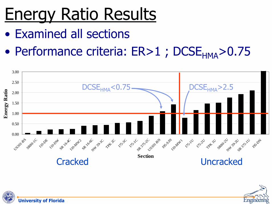
• Examined all sections• Performance criteria: ER>1 ; DCSEHMA>0.75
0.00
0.50
1.00
1.50
2.00
2.50
3.00
US301-B
SSR80-1
CI10
-DE
I10-D
WSR 16-4
CI10
-MW
2SR 16-6
CNW 39-1
CTPK 2C
I75-3C
I75-1C
SR 375-2C
US301-B
NI95
-SJNI10
-MW
1I75
-1U
I75-2U
TPK 1USR80-2
UNW 39-2
USR 375
-1UI95
-DN
Section
Ene
rgy
Rat
io
Cracked Uncracked
DCSEHMA<0.75 DCSEHMA>2.5
Energy Ratio Results

Fracture Mechanics to Explain Failure Mechanisms
in Pavement Systems

University of Florida
σTOP = σBOTBottom Crack More Likely
σTOP = σBOTBut Intensity
MakesTop Crack
More Likely
*One Explanation for Top-down Cracking
. . .
. . .. . .. . .
. . .
. . .
. . .
. . .. . .. . .
. . .
. . .
. . .
. . .. . .. . .
. . .
. . .
. . .
. . .. . .. . .
. . .
. . .
. . .
. . .. . .. . .
. . .
. . .
. . .
. . .. . .. . .
. . .
. . .
. . .
. . .. . .. . .
. . .
. . .
. . .
. . .. . .. . .
. . .
. . .
. . .
. . .. . .. . .
. . .
. . .
. . .
. . .. . .. . .
. . .
. . .
σTOP σTOP
. . .
. . .. . .. . .
. . .
. . .
. . .
. . .. . .. . .
. . .
. . .σBOT
. .. .
..
.
.
. . .
. . .. . .. . .
. . .
. . .
. . .
. . .. . .. . .
. . .
. . .
. . .
. . .. . .. . .
. . .
. . .
. . .
. . .. . .. . .
. . .
. . .σBOT
. .. .
..
.
.
Effect of Crack on Failure Mode
University of Florida
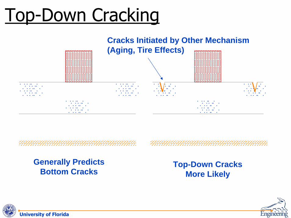
Generally Predicts Bottom Cracks
Top-Down Cracks More Likely
Cracks Initiated by Other Mechanism (Aging, Tire Effects)
. . .
. . .. . .. . .
. . .
. . .
. . .
. . .. . .. . .
. . .
. . .. . .. . .
. . .
. . .. . .. . .
. . .
. . .. . .. . .
. . .
. . .
. . .
. . .. . .. . .
. . .
. . .
. . .
. . .. . .. . .
. . .
. . .
. . .
. . .. . .. . .
. . .
. . .
. . .
. . .. . .. . .
. . .
. . .. . .. . .
. . .
. . .. . .. . .
. . .
. . .. . .. . .
. . .
. . .
. . .
. . .. . .. . .
. . .
. . .
. . .
. . .. . .. . .
. . .
. . .
Top-Down Cracking

University of Florida
Example
Is Bond Layer•Tough Enough?•Thick Enough?Will Crack Initiate Below Bond Layer?
FM Can Be Used to Optimize the System.Develop Guidelines
Bonded Surface (e.g. Friction courses)
High Toughness Bond Layer(e.g. Polymer Modified)
Fracture Mechanics for Pavement System Solutions

Fracture Mechanics For Mixture Design

University of Florida
Coarser Finer
Microcracks Develop in Areas of High Stress ConcentrationAggregate Structure/Resulting Microcrack Distribution Affects Fracture Resistance. (Note: Other Factors Also Important)
Void/Flaw Structure and Distribution

University of Florida
Pinning Polymers/Fibers
Holes or “Soft” Additive Polymers or Fibers
Holes or Additive Reduce Stress Intensity
Mitigate Crack Growth
Polymers or Fibers Reduce Stress Intensity
Reduce Rate of Crack Growth
Modifiers And Fracture Mechanics

Fracture Simulators
University of Florida
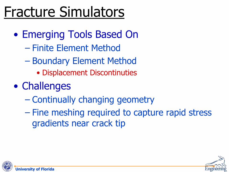
• Emerging Tools Based On– Finite Element Method– Boundary Element Method
• Displacement Discontinuties
• Challenges– Continually changing geometry– Fine meshing required to capture rapid stress
gradients near crack tip
Fracture Simulators
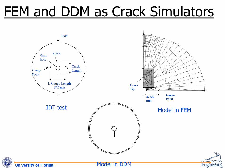
University of Florida Model in DDM
IDT test
Load
crack
L-Gauge Length37.5 mm
Gauge Point
Crack Length
8mm hole
Crack Tip
Gauge Point
37.5/2 mm
Model in FEM
FEM and DDM as Crack Simulators

University of Florida
H3
0.79-MPa tire pressure 4.826 m 4.826 m
5.08 m.
H2 H1
Subgrade
Subbase Base
Asphalt Mixture 25.4 mm width
Initial Crack
Modeling of a Four-Layer Pavement Structure with a Crack

University of Florida
At beginning, 6.35-mm crack length
Crack growth Step 1, 12.7-mm crack length after 72,999 loads
Crack growth Step 2, 19.05-mm crack length after 113,590 loads
Crack growth Step 4, 31.75-mm crack length after 176 736 loads
Crack growth Step 3, 25.4-mm crack length after 146,059 loads
Crack growth Step 5, 38.1-mm crack length after 208 447 loads
Automated Crack Growth: Pavement Section on I-10

University of Florida
AB
C
Total Fracture Energy
-18° 0 +18°
Angle
AB
C
A
B
C
A
B
C
A
B
C
α
α
r
crack
Direction of Crack Growth

University of Florida
• An Important Tool for Continued Advancement of Pavement Systems and Mixtures that Mitigate Cracking
• Continued Development and Verification of Fracture Mechanics Theory and Understanding Will Lead To:– Pavement systems that mitigate cracking– Improved guidelines for fracture resistant mixtures– Simple and effective tests for asphalt material design,
specification, and quality control• Enhances Efforts and Understanding Being
Pursued By Way Of Micro-structural and Damage Analysis
HMA Fracture Mechanics: Summary