hmi software manual
DESCRIPTION
Manual tecnicoTRANSCRIPT

FLOWATCH
MULTIPHASE FLOW METER
Doc.: MT-155
Rev. F
HMI Software Manual Sh. 1 of 62
F Added new functionality and changes for
version upgrade 18/06/09 F. Lucchini S. Bernardi
E Added new HMI functionality 10/06/08 F. Lucchini S. Bernardi
D Major Revision of software 03/03/08 M. Capiluppi S. Bernardi
C Add parameter description / HMI rel. 1.020 27/11/07 M. Capiluppi P. Calciolari
B New HMI interface 16/11/07 S. Bernardi P. Calciolari
A First issued 16/05/06 S. Bernardi P. Calciolari
REV. DESCRIPTION DATA PREPARED APPROVED
MULTIPHASE FLOW METER
HUMAN MACHINE INTERFACE (HMI)
SOFTWARE MANUAL
Prepared for HMI version 3.002 and FlowCalc version 3001
FLOWATCH
MULTIPHASE FLOW METER
Doc.: MT-155
Rev. F
HMI Software Manual Sh. 2 of 62
INDEX
1. INTRODUCTION ................................................................................................................... 4
1.1 FlowCalc....................................................................................................................... 4
1.2 HMI............................................................................................................................... 5
2. FLOWCALC .......................................................................................................................... 6
2.1 REAL TIME CONTROLER ........................................................................................... 6
2.2 FTP access................................................................................................................... 7
2.3 FLOW COMPUTER File Overview................................................................................ 8
2.4 FLOW COMPUTER Web-Server Function.................................................................... 9
3. HMI...................................................................................................................................... 10
3.1 HMI Operation ............................................................................................................ 10
3.2 Main Screen ............................................................................................................... 10
3.2.1 The standard Main Screen................................................................................10
3.2.2 User Parameters...............................................................................................11
3.2.3 Language..........................................................................................................12
3.2.4 Alarms 13
3.3 HMI File Overview ...................................................................................................... 14
3.4 Menu .......................................................................................................................... 15
3.4.1 F1 – Input Parameters ......................................................................................15
3.4.1.1 Parameter Groups and Files ..............................................................16
3.4.1.2 Synchronization of Parameters .........................................................17
3.4.1.3 Offline Parameter Editing ...................................................................18
3.4.1.4 F1 – Parameter File Editor ..................................................................19
3.4.1.5 F2 – Transmitter Settings ...................................................................20
3.4.1.6 F3 – Fluids ...........................................................................................22
3.4.1.7 F5 – PVT 25
3.4.1.8 F6 – FEB Certificate ............................................................................28
3.4.1.9 F7 – Sensor Certificate .......................................................................29
3.4.1.10 F9 – Meter Factors...............................................................................30

FLOWATCH
MULTIPHASE FLOW METER
Doc.: MT-155
Rev. F
HMI Software Manual Sh. 3 of 62
3.4.2 F2 – Well Files Utility ........................................................................................31
3.4.3 F3 – Well Profiles..............................................................................................32
3.4.4 F4 – Database ..................................................................................................35
3.4.4.1 F1 – DB Files........................................................................................35
3.4.4.2 F2 – Report Setup................................................................................39
3.4.4.3 F3 – Generate Report ..........................................................................40
3.4.4.4 F4 – Units .............................................................................................42
3.4.5 F5 – FLOW COMPUTER Setup........................................................................43
3.4.5.1 FLOW COMPUTER - MODBUS Settings ............................................45
3.4.5.2 LOCAL DISPLAY UNITS......................................................................49
3.4.5.3 EXTERNAL GAS METER SETTING ....................................................50
3.4.5.4 CONTROL VALVE SETTING ...............................................................50
3.4.5.5 ANALOG OUTPUTS SETTING ............................................................51
3.4.5.6 FLOW COMPUTER TIME AND DATE SETTING.................................52
3.4.6 F6 – Meter Selection (TCP/IP) ..........................................................................53
3.4.7 F7 – Units..........................................................................................................55
3.4.8 F8 – Service Mode............................................................................................56
3.4.9 F9 – Exit............................................................................................................57
4. LOCAL DISPLAY (OPTIONAL) .......................................................................................... 58
5. LOCAL DISPLAY – TOUCH-SCREEN................................................................................ 60

FLOWATCH
MULTIPHASE FLOW METER
Doc.: MT-155
Rev. F
HMI Software Manual Sh. 4 of 62
1. INTRODUCTION
This is the User Manual for the HMI (Human Machine Interface) used for the FloWatch Multiphase flow meter.
The software required for running the FloWatch multiphase meter consists of two programs run on two different computers.
• The “FlowCalc” software is run on a dedicated Real Time Controller, “FLOW COMPUTER” (described below)
• The “HMI” software run on any Windows based PC in the same network as the FLOW COMPUTER
1.1 FlowCalc.
The “FlowCalc” software run on a “FLOW COMPUTER” computer developed by National Instrument. The FLOW COMPUTER consists of the main computer module with various input modules attached running on an FPGA module.
The software is run on a real-time operating system and the computer does not have any keyboard or monitor attached.
The communication with the outside worlds will normally be through TCP/IP.
The FlowCalc software on the Flow Computer performs the following tasks:
• Data Acquisition from Analogue inputs (Transmitters)
• Data Acquisition from Serial port (FEB)
• Data Processing (from input data to calculated results)
• Logging to local Database and Service Database
• Storing of all Setup and Parameter files
• Communication with HMI software and wireless PDA (through TCP/IP).
• Communication with External Data Acquisitions systems through either serial communication or TCP/IP. Also analogue output modules can be installed upon request.
• Web Server function for communication with Local Display or external Computers without using the HMI software
In addition to this the FLOW COMPUTER can be accessed by regular FTP for new program versions or quick download of database files.
The HMI software is not required for the FloWatch multiphase meter during regular operation.

FLOWATCH
MULTIPHASE FLOW METER
Doc.: MT-155
Rev. F
HMI Software Manual Sh. 5 of 62
1.2 HMI.
The HMI software can be run on a dedicated Windows PC or on any other computers running Windows on the same network that the FLOW COMPUTER is on.
The HMI has the following functionalities:
• Display of live inputs and results
• Setup and synchronizing of parameter setup files
• Setup of FLOW COMPUTER settings, Modbus, time and date etc.
• Downloading and converting of Database files
• Preparing well test report
• Diagnostic tools (Service Level only)
There are three log-on levels to the HMI. This manual describes the USER log-on level. The VIEWER level is a very restricted subset of the USER functionality.

FLOWATCH
MULTIPHASE FLOW METER
Doc.: MT-155
Rev. F
HMI Software Manual Sh. 6 of 62
2. FLOWCALC
2.1 REAL TIME CONTROLER
The default FlowCalc software will normally run on a cRIO-9012. There are however several other versions available depending on the actual use. The c_RIO has been chosen as the FloWatch REAL TIME CONTROLLER due to the wide temperature range and the very practical physical size and robustness featured. The information below has been gathered from the Internet site of National Instrument who manufactures the computer. More information can be found at www.ni.com/compactrio/.
• Embedded controller runs LabVIEW Real-Time for deterministic control, data logging, and analysis
• 400 MHz processor, 128 MB non-volatile storage, 64 MB DRAM memory
• 10/100BaseT Ethernet port with embedded Web and file servers with remote-panel user interface
• Full-speed USB host port for connection to USB flash and memory devices
• RS232 serial port for connection to peripherals; dual 9 to 35 VDC supply inputs
• -40 to 70 °C operating temperature range
The National Instruments cRIO-9012 embedded real-time controller features an industrial 400 MHz Freescale MPC5200 real-time processor for deterministic and reliable real-time

FLOWATCH
MULTIPHASE FLOW METER
Doc.: MT-155
Rev. F
HMI Software Manual Sh. 7 of 62
applications. The NI cRIO-9012 contains 64 MB of DRAM memory and 128 MB of non volatile storage. The embedded controller is designed for extreme ruggedness, reliability, and low power consumption with dual 9 to 35 VDC supply inputs that deliver isolated power to the Compact RIO chassis/modules and a -40 to 70 °C operating temperature range. The cRIO-9012 accepts 9 to 35 VDC power supply inputs on power-up and 6 to 35 VDC power supply inputs during operation, so it can function for long periods of time in remote applications using a battery or solar power. With the 10/100 Mb/s Ethernet port, you can conduct programmatic communication over the network and built-in Web (HTTP) and file (FTP) servers. For additional storage capability, the cRIO-9012 has a full-speed USB host port to which you can connect external USB-based storage media (flash drives and hard drives) for embedded logging applications requiring additional storage. Also, there is a fault-tolerant file system embedded in the cRIO-9012 that provides increased reliability for data-logging applications. The cRIO-9012 runs the National Instruments LabVIEW Real-Time Module on the VxWorks real-time operating system (RTOS) for extreme reliability and determinism. With the cRIO-9012 real-time controller, you can use the leading VxWorks RTOS technology to quickly design, prototype, and deploy a customizable COTS embedded system using LabVIEW graphical programming tools.
2.2 FTP access
The FLOW COMPUTER can be accessed using Internet Explorer by FTP to update program files or download setup/log files. This is normally not necessary as the HMI software has the function for changing and downloading of these files as well.
By using the FTP access the directory structure of the FLOW COMPUTER can be found.

FLOWATCH
MULTIPHASE FLOW METER
Doc.: MT-155
Rev. F
HMI Software Manual Sh. 8 of 62
2.3 FLOW COMPUTER File Overview
The table below shows the files in use by the FlowCalc software.
File Directory Comments
FlowCalc.rtexe C:\ni-rt\startup Main real-time executable
FlowCalc.aliases Support File
FlowCalc Setup.txt C:\ General Setup (i.e. modbus, modbus units)
Calculation File.clc C:\Parameters General Calculation Setup
Meter File.mtr Meter File
Well File.wll Default Well File
Well Profile File.pro Well Profile File (only if well profile is set up on computer)
*.wll Various Well Files
Calibration Tables.tbl Lookup tables for calibration, properties and PVT(only if tables are set up on computer)
PF DataBase yyyymmdd.dat
C:\Data\DataBase Customer database (binary file format)
PF Service DB 20070624.dat
C:\Data\Service DB Service database (binary file format)
PF yyyymmdd hh00.bin
C:\Data\Bin\yyyy\mm\dd Hourly BIN Files
PF yyyymmdd hhmm.bix
C:\Data\Bix\yyyy\mm\dd 1 Minute BIX files
The content of all the setup files are available and will normally be changed from the HMI program.

FLOWATCH
MULTIPHASE FLOW METER
Doc.: MT-155
Rev. F
HMI Software Manual Sh. 9 of 62
2.4 FLOW COMPUTER Web-Server Function
The FLOW COMPUTER has a built in Web-Server function and the calculated results can be seen directly by using Internet Explorer.
The Flow Computer Web-Server is being used one version of “Local Display” explained at the end of this document.
This section will be updated as the web-server function is still under development.

FLOWATCH
MULTIPHASE FLOW METER
Doc.: MT-155
Rev. F
HMI Software Manual Sh. 10 of 62
3. HMI
3.1 HMI Operation
The HMI can be started by opening “PF HMI.exe” from any computer in the same network as the FLOW COMPUTER where the FlowCalc software is running.
3.2 Main Screen
3.2.1 The standard Main Screen
The standard main screen for the HMI is shown below.
This screen will show live results values both by numbers and by graphical presentation and transmitter values only by numbers presentation.
Results and parameter selection
FLOWATCH
MULTIPHASE FLOW METER
Doc.: MT-155
Rev. F
HMI Software Manual Sh. 11 of 62
It also shows to which FLOW COMPUTER (well) the software is connected to.
The menu is to the right and is grouped similar to the F1 to F12 buttons on a regular keyboard. The F1-12 buttons can therefore be used as shortcuts to the menus.
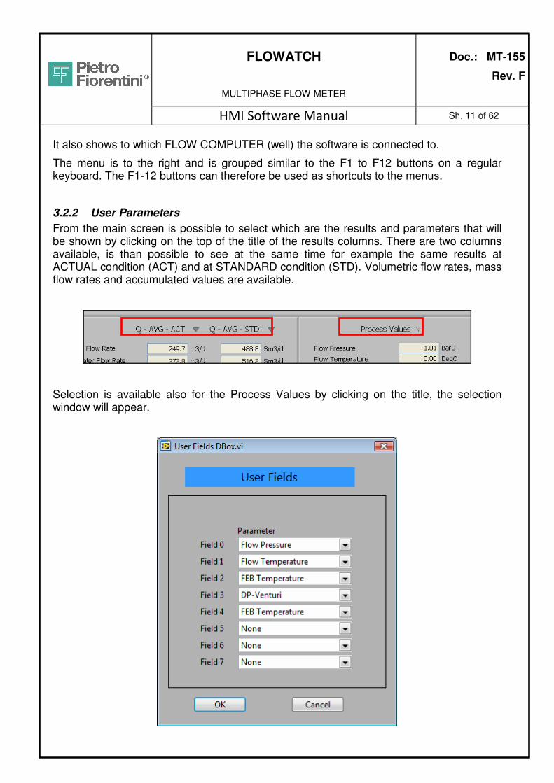
3.2.2 User Parameters
From the main screen is possible to select which are the results and parameters that will be shown by clicking on the top of the title of the results columns. There are two columns available, is than possible to see at the same time for example the same results at ACTUAL condition (ACT) and at STANDARD condition (STD). Volumetric flow rates, mass flow rates and accumulated values are available.
Selection is available also for the Process Values by clicking on the title, the selection window will appear.

FLOWATCH
MULTIPHASE FLOW METER
Doc.: MT-155
Rev. F
HMI Software Manual Sh. 12 of 62
3.2.3 Language
The HMI is multi-language software and can be set to various different languages.
The language strings are controlled from the txt file “FloWatch - Language Overview - ver 002.txt” which needs to be located under the HMI root directory.
Simply press the small “LNG” button on the status bar on the main screen and the various language options will come up as showed below. Select the desired language than click “OK”.
New language translations can easily be made upon requests and no reprogramming of the HMI is necessary to add new languages.

FLOWATCH
MULTIPHASE FLOW METER
Doc.: MT-155
Rev. F
HMI Software Manual Sh. 13 of 62
3.2.4 Alarms
By pressing the Red or Green status button on the main screen the following dialog box will appear.
The screen will default to “Current Alarms” and show the status of the active alarms only.
By changing from “Current Alarms” to “Alarm Status” all alarm parameters and their status, readings and limits will be shown. You have to select Alarm Status to be able to update the alarm limits.
The alarms have only the scope, at least for the moment, to advise the operator if present that some readings or measurements are wrong. No action from the system will be taken.
The last 10 alarms are also transmitted through modbus.

FLOWATCH
MULTIPHASE FLOW METER
Doc.: MT-155
Rev. F
HMI Software Manual Sh. 14 of 62
3.3 HMI File Overview
The following files and directories are used:
Directory File Comments C:\root\ PF HMI.exe Main executable
C:\root\ HMI Setup.txt General Setup
FloWatch - Language Overview – Ver 002.txt
Contains all TXT strings for language control
C:\root\Parameters Calculation File.clc General Calculation Setup
Meter File.mtr Meter File
Well File.wll Default Well File
Well Profile File.pro Well Profile File
*.wll Various Well Files
C:\root\Meters\”Tag No” \Parameters
All Flow Computer Files These are the synchronized setup and parameter files copied from each TCP/IP connection to a Flow Computer (each Flow Computer will have its own “Tag No”)
C:\root\Meters\”Tag No” \Database
Flow Computer Database files
Directory for downloading of database files from the Flow Computer
C:\root\Templates Well Test Report.xls Excel Template used for reports.
There is no file logging from the HMI software except for “Calibration Log.txt” which is a “manual” log under Service Level. The previous “Table file” is no longer in use.

FLOWATCH
MULTIPHASE FLOW METER
Doc.: MT-155
Rev. F
HMI Software Manual Sh. 15 of 62
3.4 Menu
3.4.1 F1 – Input Parameters
By pressing the “Input Parameters” button from the main screen or “F1”, the menu buttons will change names as shown below.
Any multiphase meter will use a number of input parameters for the flow calculations to work properly. It is of course sufficient that one of the parameters is wrong for the final outcome to be incorrect.
Great care should therefore be taken to understand this chapter about input parameters so no accidental update of wrong parameters takes place.

FLOWATCH
MULTIPHASE FLOW METER
Doc.: MT-155
Rev. F
HMI Software Manual Sh. 16 of 62
3.4.1.1 Parameter Groups and Files
The table below shows where the different parameter groups are stored.
Parameter Group Parameter File Comments
Transmitters Meter 4-20 mA analog input readings from transmitters (P, DP, T +++)
Fluids Well Oil Density Oil Permittivity Water Density Water Conductivity Gas Specific Gravity
PVT Well Oil Shrinkage Gas Compressibility Gas in Solution Reference Conditions (P&T)
FEB Certificate Meter Capacitance and Conductance conversions for the FEB
Sensor Certificate Meter Permittivity and Conductivity conversions for the Sensor
Dimensions (Mech.) Meter Mechanical Dimensions of the sensor
Meter Factors Well Optional User Meter Factors for results

FLOWATCH
MULTIPHASE FLOW METER
Doc.: MT-155
Rev. F
HMI Software Manual Sh. 17 of 62
3.4.1.2 Synchronization of Parameters
The principle for the synchronization of the Parameters goes like this:
1 During the initialization of the HMI software, the last parameters that were stored in the Parameter File Editor will be reloaded.
2 Upon connection with a FLOW COMPUTER all parameters will be read from the FLOW COMPUTER files, updated in the Editor and stored in a “C:/root/Meters/” Tag No/Parameters” directory. This way the HMI will always have the last settings from the FLOW COMPUTER also after disconnecting from the FLOW COMPUTER.
3 By changing any of the parameters in the dialog boxes while a connection is up and running, the values will automatically be sent to the FLOW COMPUTER and stored in the FLOW COMPUTER parameter files. For synchronization purposes also the file under the HMI “Tag No” directory will be updated.
4 By changing from one well to the other, a new synchronization will take place, this time the files will be stored in another Tag No directory.
The following five files will be stored during the synchronization:
1 CRIO Well File.wll (One or more well files)
2 CRIO Meter File.mtr
3 CRIO Calculation File.clc
4 CRIO Profile.pro
5 CRIO Setup.txt
The files will be available in the HMI also after the connection to the FLOW COMPUTER has been made and can manually be loaded from the “Parameter File Editor” described later in this manual.
The files will be overwritten the next time the HMI connects to a FLOW COMPUTER with the same “Tag No”.
If the FLOW COMPUTER files are to be used for offline editing they have to be copied or moved to a different directory prior to the next connection to the same “Tag No”.

FLOWATCH
MULTIPHASE FLOW METER
Doc.: MT-155
Rev. F
HMI Software Manual Sh. 18 of 62
3.4.1.3 Offline Parameter Editing NB! Great care should be taken to understand this chapter about input parameters so no accidental update of the wrong parameters take place.
The offline editing can take place after a connection with a FLOW COMPUTER has been closed or by manually loading other files in the Parameter File Directory. If an offline editing takes place, the automatic synchronization with the FLOW COMPUTER will be disabled so the parameters will no longer be sent automatically to the FLOW COMPUTER, just stored in the local file in the HMI. This file cannot be located in any “Tag No” directory as they are reserved for exact copies of the setup and parameter files in the FLOW COMPUTERs. In case of offline editing and modification of the setup files, it is recommended to copy those files to a separate folder, or alternatively it is possible to make a copy of those files and rename them.

FLOWATCH
MULTIPHASE FLOW METER
Doc.: MT-155
Rev. F
HMI Software Manual Sh. 19 of 62
3.4.1.4 F1 – Parameter File Editor The file editor below is used to transfer parameter files between FLOW COMPUTER and the HMI computer.
If connection is established with a FLOW COMPUTER the Files in Editor will be the same as the ones used by the FLOW COMPUTER.
To upload a new parameter file that has been edited in Offline condition, simply select “Load” button, than select the desired file from the list and then “Exit”.
This operation will lead to the following three actions:
1 The file will be sent to the FLOW COMPUTER global and stored in the FLOW COMPUTER parameter file in the FLOW COMPUTER.

FLOWATCH
MULTIPHASE FLOW METER
Doc.: MT-155
Rev. F
HMI Software Manual Sh. 20 of 62
2 The file will overwrite the FLOW COMPUTER file in the HMI directory
3 The parameters will be loaded in the Parameter Editor so they are available from all menus.
As long a connection to a FLOW COMPUTER is established the “green led” will be activated, “light green colour”, which means that the FLOW COMPUTER parameter files are synchronized.
It is now possible to stop the Synchronization by pressing the “Stop Synchronization” or to resynchronize which will override the synchronized parameter files again.
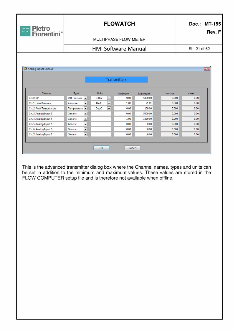
3.4.1.5 F2 – Transmitter Settings
There are two Transmitter Settings dialog boxes. A simple dialog box will come up is the HMI is not connected to any FLOW COMPUTER, (OFF LINE MODE). A more advanced dialog box will show up if the HMI is connected where more settings can be entered.
This dialog box gives access to the parameters controlling the analogue input settings of the transmitters. Analogue input from 0 to 2 are the basic inputs in use on the system, starting from Differential pressure, then Pressure and final Flow Temperature.
Inputs from 3 to 7 are spare and available for different and others application, for example external gas meter or similar. The intrinsically safe barriers for the spare inputs are not provided on the standard configuration.
Units can be changed directly from this window by selecting the UNITS green button. For more detailed explanation regarding the Units menu see section 3.4.7 of this manual.
FLOWATCH
MULTIPHASE FLOW METER
Doc.: MT-155
Rev. F
HMI Software Manual Sh. 21 of 62
This is the advanced transmitter dialog box where the Channel names, types and units can be set in addition to the minimum and maximum values. These values are stored in the FLOW COMPUTER setup file and is therefore not available when offline.
FLOWATCH
MULTIPHASE FLOW METER
Doc.: MT-155
Rev. F
HMI Software Manual Sh. 22 of 62
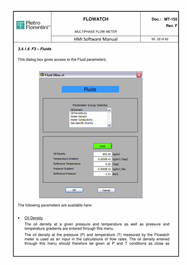
3.4.1.6 F3 – Fluids
This dialog box gives access to the Fluid parameters.
The following parameters are available here:
• Oil Density
The oil density at a given pressure and temperature as well as pressure and temperature gradients are entered through this menu.
The oil density at the pressure (P) and temperature (T) measured by the Flowatch meter is used as an input in the calculations of flow rates. The oil density entered through this menu should therefore be given at P and T conditions as close as

FLOWATCH
MULTIPHASE FLOW METER
Doc.: MT-155
Rev. F
HMI Software Manual Sh. 23 of 62
possible to the operating P and T conditions of the Flowatch meter. Linear pressure and temperature gradients can also be entered through this menu. The pressure gradient gives the change in the oil density if the pressure is increased by 1 bar (or 1 psi if psi is selected as units). Likewise the temperature gradient gives the change in the oil density if the temperature is increased by 1degC (or 1degF if degF is selected as units). TG-Ref Temperature and PG-Ref Pressure are the temperature and pressure associated with the Oil Density given in the top of the list above.
• Oil Permittivity
The oil permittivity at a given pressure and temperature as well as pressure and temperature gradients are entered through this menu (A different name used in the industry permittivity is the term dielectric constant).
The oil permittivity at the pressure (P) and temperature (T) measured by the Flowatch meter is used as an input in the calculations of flow rates. The oil permittivity entered through this menu should therefore be given at P and T conditions as close as possible to the operating P and T conditions of the Flowatch meter. Linear pressure and temperature gradients can also be entered through this menu. The pressure gradient gives the change in the oil permittivity if the pressure is increased by 1 bar (or 1psi if psi is selected as units). Likewise the temperature gradient gives the change in the oil permittivity if the temperature is increased by 1degC (or 1degF if degF is selected as units). TG-Ref Temperature and PG-Ref Pressure are the temperature and pressure associated with the Oil Permittivity given in the top of the list above.
• Water Density
The water density at a given pressure and temperature as well as pressure and temperature gradients are entered through this menu.
The water density at the pressure (P) and temperature (T) measured by the Flowatch meter is used as an input in the calculations of flow rates. The water density entered through this menu should therefore be given at P and T conditions as close as possible to the operating P and T conditions of the FloWatch meter. Linear pressure and temperature gradients can also be entered through this menu. The pressure gradient gives the change in the water density if the pressure is increased by 1 bar (or 1psi if psi is selected as units). Likewise the temperature gradient gives the change in the water density if the temperature is increased by 1degC (or 1degF if degF is selected as units). TG-Ref Temperature and PG-Ref Pressure are the temperature and pressure associated with the Water Density given in the top of the list above.
• Water Conductivity
The water conductivity at a given pressure and temperature is entered through this menu.

FLOWATCH
MULTIPHASE FLOW METER
Doc.: MT-155
Rev. F
HMI Software Manual Sh. 24 of 62
The water conductivity at the pressure (P) and temperature (T) measured by the Flowatch meter is used as an input in the calculations of flow rates. Ref Temperature and Ref Pressure are the temperature and pressure associated with the Water Conductivity given in the top of the list above.
There is a known relationship for the change in conductivity due to changes in temperature and pressure and therefore temperature and pressure gradients are not required in this menu.
• Gas Specific Gravity
The specific gas gravity is entered through this menu. The gas density at a given pressure and temperature is derived by the Flowatch meter using the specific gas gravity as input. Also the Gas Isentropic Coefficient can be entered here. Leave this value at 0 if it is not known. A default value will then be used.

FLOWATCH
MULTIPHASE FLOW METER
Doc.: MT-155
Rev. F
HMI Software Manual Sh. 25 of 62
3.4.1.7 F5 – PVT
This dialog box gives access to the PVT parameters.
The following parameters are available here:
• Oil Shrinkage factor
The oil shrinkage factor gives the reduction in volume as the pressure and temperature of the oil phase is reduced to atmospheric pressure and standard temperature.

FLOWATCH
MULTIPHASE FLOW METER
Doc.: MT-155
Rev. F
HMI Software Manual Sh. 26 of 62
The oil shrinkage factor at a given pressure and temperature as well as pressure and temperature gradients are entered through this menu.
The oil shrinkage factor measured at the pressure (P) and temperature (T) is used as an input in the calculation of oil flow rate at stock tank conditions. Oil shrinkage factor entered through this menu should therefore be given at P and T conditions as close as possible to the operating P and T conditions of the Flowatch meter. Linear pressure and temperature gradients can also be entered through this menu. The pressure gradient gives the change in the oil shrinkage factor if the pressure is increased by 1bar (or 1psi if psi is selected as units). Likewise the temperature gradient gives the change in the oil shrinkage factor if the temperature is increased by 1degC (or 1degF if degF is selected as units). TG-Ref Temperature and PG-Ref Pressure are the temperature and pressure associated with the oil shrinkage factor given in the top of the list above.
• Gas Compressibility
The gas compressibility gives a coefficient used when calculating the increase in gas volume as the pressure and temperature of the gas is reduced to atmospheric pressure and standard temperature.
The gas compressibility coefficient at a given pressure and temperature as well as pressure and temperature gradients are entered through this menu.
The gas compressibility measured at the pressure (P) and temperature (T) is used as an input in the calculation of gas flow rate at standard conditions. Gas compressibility entered through this menu should therefore be given at P and T conditions as close as possible to the operating P and T conditions of the Flowatch meter. Linear pressure and temperature gradients can also be entered through this menu. The pressure gradient gives the change in the gas compressibility coefficient if the pressure is increased by 1bar (or 1psi if psi is selected as units). Likewise the temperature gradient gives the change in gas compressibility coefficient if the temperature is increased by 1degC (or 1degF if degF is selected as units). TG-Ref Temperature and PG-Ref Pressure are the temperature and pressure associated with the gas compressibility coefficient given in the top of the list above.
• Gas in Solution
The GOR (Gas-oil-ratio) in solution gives a factor used when calculating the amount of gas released/flashed from the oil phase as the pressure and temperature is reduced to atmospheric pressure and standard temperature.
The Gas in solution at a given pressure and temperature as well as pressure and temperature gradients are entered through this menu.
The Gas in solution measured at the pressure (P) and temperature (T) is used as an input in the calculation of gas flow rate at standard conditions. GOR in solution entered through this menu should therefore be given at P and T conditions as close as

FLOWATCH
MULTIPHASE FLOW METER
Doc.: MT-155
Rev. F
HMI Software Manual Sh. 27 of 62
possible to the operating P and T conditions of the Flowatch meter. Linear pressure and temperature gradients can also be entered through this menu. The pressure gradient gives the change in the Gas in solution if the pressure is increased by 1bar (or 1psi if psi is selected as units). Likewise the temperature gradient gives the change in GOR in solution if the temperature is increased by 1degC (or 1degF if degF is selected as units). TG-Ref Temperature and PG-Ref Pressure are the temperature and pressure associated with the GOR in solution given in the top of the list above.
• Reference Conditions (P&T)
The pressure and temperature to be represented as standard conditions can be set in the Sub-group Conversion Reference (P&T).
The reference standard pressure is normally atmospheric conditions (1.01325BarA). The temperature defined as standard conditions may vary from one oil company to the other and it is therefore possible to set the temperature from this menu.

FLOWATCH
MULTIPHASE FLOW METER
Doc.: MT-155
Rev. F
HMI Software Manual Sh. 28 of 62
3.4.1.8 F6 – FEB Certificate This menu gives access to the calibration constants in the FEB certificate which controls the conversion from binary values to capacitance/current/voltage. New FEB Certificate (text file version) can be read by selecting “Read FEB Certificate from File”. The new values will be sent when “OK” is pressed to leave the menu. The TEXT CALIBRATION FILE txt format is made in the Pietro Fiorentini Factory. The previous temperature coefficients for current and voltage measurements have been moved from the old “table file” no longer in use and are now hard-coded in the FlowCalc software. Simply select “FEB 2008 Table” for both Current TC and Voltage TC. Values can also be manually entered from hard copy of the Calibration Certificate.

FLOWATCH
MULTIPHASE FLOW METER
Doc.: MT-155
Rev. F
HMI Software Manual Sh. 29 of 62
3.4.1.9 F7 – Sensor Certificate This menu gives access to the calibration constants in the Sensor certificate which controls the conversion from capacitance to permittivity and from current/voltage to conductivity. New Sensor Certificate (text file version) can be read from here selecting the “Read Sensor Certificate from File” button then the parameters will be uploaded to the FLOWCOMPUTER by simply pressing “OK”. The TEXT CALIBRATION FILE txt format is made in the Pietro Fiorentini Factory. Values can also be entered manually from a HW copy of the Calibration Certificate.

FLOWATCH
MULTIPHASE FLOW METER
Doc.: MT-155
Rev. F
HMI Software Manual Sh. 30 of 62
3.4.1.10 F9 – Meter Factors This menu gives access to a set of meter factors that can be used in case the results should “match” a certain reference reading. The meter factor will NOT influence the results if all 1order factors are equal 1.0, while the 0.order and 2.order factors are zero. The 1.order is the best one to use for correcting flow rates. If only the 1.order is used the flow rates will be 10% higher if a value of 1.1 is used, while they will be 10% lower if a value of 0.9 is used. Metering Factors The oil, water and gas flow rate is converted according to the following formula: Qoil = 2.order * Qoil^2 + 1.order * Qoil + 0.order

FLOWATCH
MULTIPHASE FLOW METER
Doc.: MT-155
Rev. F
HMI Software Manual Sh. 31 of 62
3.4.2 F2 – Well Files Utility
The Well File is a utility where the well files containing the Fluid, PVT and Meter Factor information, can be organized.
The Well Files Utility can be used to transfer, copy and delete both well file located on the FLOW COMPUTER (if logged on), and well files stored on the HMI computer.
It is not sufficient to send a new well file to the FLOW COMPUTER. The file will just be stored there but NOT used. See next chapter for storing/transferring parameters.
Transfering button

FLOWATCH
MULTIPHASE FLOW METER
Doc.: MT-155
Rev. F
HMI Software Manual Sh. 32 of 62
3.4.3 F3 – Well Profiles
The Well Profile utility is now required to be set up with at least one profile with a corresponding well file. In addition to changing the profile in use through this dialog box, the well profiles can be selected through Modbus command. This makes the profiles a very useful tool where the FloWatch meter can be controlled remotely.
The Well Profile is a utility that can be used where a FloWatch multiphase meter is used for sequential well testing of several oil wells where individual wells require individual fluid and/or PVT inputs.
If a meter is used for 15 wells there might still only be 3 different profiles necessary. Each profile will then normally have a separate Well File associated to the profile. The active profile can be changed from the menu below or through values sent through a Modbus link directly to the FLOW COMPUTER.
Prior to setting up the various well profiles, the associated well files have to be made. The files can be made from the HMI program see chapter 3.4.2. or simply by adding copies of

FLOWATCH
MULTIPHASE FLOW METER
Doc.: MT-155
Rev. F
HMI Software Manual Sh. 33 of 62
a well file using Windows Explorer. The new well files can then later be modified with the new parameters.
After the necessary well files have been made in the HMI, the profiles can be prepared.
There are two ways to prepare the well profiles: OFF LINE mode and ON LINE mode, when connected to a flow computer.
OFF LINE MODE:
Select a line in the box to the left and the “Profile No” and the “Well Name” can be typed in the field below the table. The associated “Well File” can be selected from a drop down list which will list all well files in the HMI/Parameters directory.
When adding a new profile a new profile number has to given as the system will not allow new profiles with the same names.
As the example above shows, several profiles can have the same well file association. The profile number is the number that will be used by Modbus to remotely change between various well files.
After the well profile has been completed it needs to be saved with a different name in order to avoid overwriting problem afterward during the connection to a flow computer. This operation can be done by selecting the “save profile as” button. This well profile can be loaded to a flow computer when connected by selecting the “folder icon on the well profile file in editor”.
The profile will than be loaded to the flow computer memory, automatically the associated well files will be transferred to the flow computer memory, if not already present.

FLOWATCH
MULTIPHASE FLOW METER
Doc.: MT-155
Rev. F
HMI Software Manual Sh. 34 of 62
ON LINE MODE:
This mode is mainly used for modify an existing well profile which is already on the flow computer memory, typically for update the fluid properties or for add a well number to the profile.
For create a new profile file from zero
Prior to proceed to prepare the profile is requested to manually transfer the well files from the HMI computer memory to the Flow computer memory. See paragraph 3.4.2.
The procedure to be followed is exactly the same as per the OFF LINE mode, any way here below it is described again.
Select a line in the box to the left and the “Profile No” and the “Well Name” can be typed in the field below the table. The associated “Well File” can be selected from a drop down list which will list all well files in the FlowComputer Parameters directory.
When adding a new profile a new profile number has to given as the system will not allow new profiles with the same names.
For modify an existing profile number
Select the desired profile number by click on top of it in the table list than if requested select and change the associated well file on the drop down list. If it is requested to change the fluids or the PVT properties, click on the “Save” button to make the desire profile number active. The selected profile is now available on the Fluids and PVT properties editor from where it will be possible to do the required changes.
See paragraph 3.4.1.7 and 3.4.1.7.
The “well profile number” is stored in the USER DATA BASE. “Well profile number”, “well profile name” and “well name” are stored on the first three columns of the DATA BASE, first two are DATA and TIME.
At any time it is possible to know which well is on test by looking at the well profile on use from one of the following places:
1 From the well profile menu
2 From the local display on the MPM cabinet if present
3 By interrogate the flow computer trough modbus register n. 40244

FLOWATCH
MULTIPHASE FLOW METER
Doc.: MT-155
Rev. F
HMI Software Manual Sh. 35 of 62
3.4.4 F4 – Database
All the logs activity are performed from the FLOW COMPUTER and saved in the FLOW COMPUTER memory. In order to save logging capacity and have smaller files, the data base files are stored using a special binary format “.dat”, which needs to be converted to a different format for regular programs to read them. The FlowCalc software is automatically logging one record (an array of results) per minute to the database file.
Pressing “Database” (F4) will make the menu buttons to the right change and the following four options become available:
• “DB Files” for transfer of database files from Flow Computer to the HMI.
• “Report Setup” for some basic setup of the txt reports and the location of the database files used for the reporting and historical data presentation
• “Generate Report” which will generate an on-screen report that can later be saved as a txt file or an Excel file (requires MS Excel on the machine!)
• “Units” as a shortcut for change of units in the reports. Remember that the Report units have to be chosen.
3.4.4.1 F1 – DB Files The “Transfer DB Files” is a utility for transferring and synchronizing the logged database files from the Flow Computer to the HMI for storing of data and generating reports.

FLOWATCH
MULTIPHASE FLOW METER
Doc.: MT-155
Rev. F
HMI Software Manual Sh. 36 of 62
When connected to a Flow Computer the table can show three different file list. To change between the lists, simply press the yellow header of the table.
• “For Synchronization” which already has compared the database files on the Flow Computer with the database files already downloaded to the HMI. Partly downloaded files will also be shown and overwritten if selected for transfer.
• All files in the Flow Computer whether they have been downloaded previous or not.
• All files in the current database directory in the HMI whether they have been downloaded previously or not.
There is also a filtering option that will filter old files. If only the last 14 days of database files are of interest, simply tick off the filter and enter 14 days. Older files will be no longer be shown. Before any file operation takes place, the user will have to select one or more files. A “select ALL files” button has been made available below the table.

FLOWATCH
MULTIPHASE FLOW METER
Doc.: MT-155
Rev. F
HMI Software Manual Sh. 37 of 62
When “Flow computer data base file” or “HMI data base file” are selected, will be also possible to delete the selected files from the respectively memory location. Be careful to use this function specially when deleting files from the flow computer, check for the availability of the file on the HMI before delete it. Data base deleted can not be restored. Remember also that, in order to keep the system working properly, delete data base files from the flow computer memory is part of the regular maintenance that must be executed on the system. The “Convert to TXT File(s)” offer a convenient way to convert the database files from the binary format to a txt-based tab-delimited format which can be read by Excel. This option is available only if “HMI data base file” is selected as show bellow.
The system automatically will create a XLS folder under the same folder where the source files are located, where the new converted files will be stored.

FLOWATCH
MULTIPHASE FLOW METER
Doc.: MT-155
Rev. F
HMI Software Manual Sh. 38 of 62
Before data base conversion it is possible to personalize the output format of the columns on the txt file and to decide the interval between the records (rows).
If the data for only a certain part of the day is of interest also the “Generate Report” function below can be used.

FLOWATCH
MULTIPHASE FLOW METER
Doc.: MT-155
Rev. F
HMI Software Manual Sh. 39 of 62
3.4.4.2 F2 – Report Setup The report setup gives the user the option to customize the results report from the HMI. The DataBase Directory parameter will normally be automatically set depending on which Flow Computer the HMI is connected to. For offline generation of reports, the correct directory (meter) has to be selected. A report will consist of two parts; a overview part and a table part (if selected). Both a txt based report and an Excel type report can be generated from the HMI and some of these settings will only have an effect on the txt report.

FLOWATCH
MULTIPHASE FLOW METER
Doc.: MT-155
Rev. F
HMI Software Manual Sh. 40 of 62
“Include Accumulated Values in Report” will have an effect only on the results overview page, not in the table part. There is a separate tick mark to include the accumulated values in the table. The Include “Table in TXT report” will only have an effect in the TXT reports as the XL reports always come with two tables; one “Average” table where the values have been averaged based on the “Record Interval”, and one “Minute” table where the average for each minute is stored. 3.4.4.3 F3 – Generate Report To generate a report, the start and stop time for the report has to be selected prior to entering the “Generate Report” menu. From the main display select “historical” in stead of “live” in the upper left corner of the graph as shown below.
The Start and Stop time will now be available at the bottom of the graph. The times can be changed by pressing the symbols to the right or selecting the hours or minutes and using the arrow buttons on the computer keyboard. After the correct time period has been selected, go back to the “Generate Report” menu. The screen below will be displayed.

FLOWATCH
MULTIPHASE FLOW METER
Doc.: MT-155
Rev. F
HMI Software Manual Sh. 41 of 62
The user can here enter special events in the “Comment” field prior to saving the report. For the “Save XLS Report” to work, the computer needs Excel installed and have the XL template “Well Test Report.xlt” located in the “C:/root/Templates” directory on the computer where the HMI program is running.

FLOWATCH
MULTIPHASE FLOW METER
Doc.: MT-155
Rev. F
HMI Software Manual Sh. 42 of 62
3.4.4.4 F4 – Units This is just convenient shortcut to the Units setup. Remember that the units from “REPORTS” are used.

FLOWATCH
MULTIPHASE FLOW METER
Doc.: MT-155
Rev. F
HMI Software Manual Sh. 43 of 62
3.4.5 F5 – FLOW COMPUTER Setup
This dialog box controls all the setting in the FLOW COMPUTER FlowCalc software.
File Versions.
On the left of the screen the various file version numbers are found:
1 HMI Program Version (always visible)
2 FLOW COMPUTER Program Version (if connected)
3 FPGA Program Version (if connected)
The FPGA program is a separate software program that is loaded on a separate FPGA on the backplane of the FLOW COMPUTER and controls all modules connected to it. The

FLOWATCH
MULTIPHASE FLOW METER
Doc.: MT-155
Rev. F
HMI Software Manual Sh. 44 of 62
“FPGA Program” cannot be changed but the version number may be read for diagnostics purposes.
BIN/BIX Log
The Bin/BIX log functions are two functionalities that are normally not activated. If these special functions are activated the system will start logging heavy loads of raw data to special files. One file per hour/10minute will be produced and stored on the memory of the FLOW COMPUTER. This logging activity requires big memory consumption, typically 4.5 Mbyte per hours for BIN files and even higher for BIX. The BIN file logging will fill up the FLOW COMPUTER memory in about one day.
To monitor the memory situation the total and free memory of the Flow Computer are displayed. Also the limit for Low Memory Limit can be set here. Default value is 10 Mb. When the Low Memory Alarms has been set on all logging to hard disc will be terminated to avoid system crash.
There is also an option to log these BIN files to a memory stick connected to the Flow Computer.
This functionality is made for service purpose mainly and for that reason it should only be kept on upon requests from service personnel.
Reset Accumulated Values
The “Reset Accumulated Values” will of course reset the results accumulators. The date/time for the last reset is displayed here. Effect take place on the live data and on the database.
Accumulated values can be reset also trough modbus. Register n. 40260

FLOWATCH
MULTIPHASE FLOW METER
Doc.: MT-155
Rev. F
HMI Software Manual Sh. 45 of 62
3.4.5.1 FLOW COMPUTER - MODBUS Settings
This menu controls the Modbus Settings and Modbus Register settings including Units only used for the Modbus registers.
There are several hardware configuration available of the FLOW COMPUTER. Not all have two serial ports and the settings for Slave 2 will have no effect. For the Modbus communication to work, the “Green activation light” next to each port has to be turned on. On the left side of the window Baud Rate, Data Bit, etc. are configurable. On the right side of the window, the Modbus version is selectable between “Legacy” and “FloWatch”. “Legacy” should only be used in special cases as it has a different Modbus map. All units used for the 30000 (input) registers can be changed and selected from this menu. The Units settings will not take effect for the 40000 (holding) registers. Two different groups of results can be also selected from the list, those will always be located on the modbus map on the register 0 to 5 and 10 to 15, but only if the “FloWatch” option is selected.
Green activation LED

FLOWATCH
MULTIPHASE FLOW METER
Doc.: MT-155
Rev. F
HMI Software Manual Sh. 46 of 62
In the “Legacy” mode only the “4X Legacy” map will be used and the 30000 registers will be inactive. View Modbus Register For diagnostics purposes the “View Modbus Register” screen has been made. The screen will read the requested registers in the FLOW COMPUTER every second using Modbus over TCP/IP. It will read the same registers available for the serial Modbus.

FLOWATCH
MULTIPHASE FLOW METER
Doc.: MT-155
Rev. F
HMI Software Manual Sh. 47 of 62
For testing of Modbus Commands also the possibility of writing floating point numbers has been made. As the button indicates, the command will execute only once the “Write the 40000 Once” button is pressed. . Modbus Commands There are several commands that can be executed through Modbus.
The graph below is taken from the FloWatch - Modbus Registers document and shows the available commands actually.
U16 40240
U16 40241
U16 40242
U16 40243
COM U16 Well Profile No OFF = 9999 40244
COM U16 BIN Log ON 0 = OFF, 1 = ON 40245
COM U16 Gas Control Valve - Auto 0 = Manual, 1 = Auto 40246
COM U16 Gas Control Valve - Opening 0 - 100% 40247
U16 40248
U16 40249
COM U16 Flow Computer Time - Hours 0 - 23 40250
U16 Flow Computer Time - Minutes 0 - 59 40251
U16 Flow Computer Time - Seconds 0 - 59 40252
U16 Flow Computer Time - Month 1 - 12 40253
U16 Flow Computer Time - Day 1 - 31 40254
U16 Flow Computer Time - Year 2000 - 2099 40255
COM U16 Flow Computer Time - Syncronize Tick Set clock to top of the hour (+/- 30 minutes) 40256
U16 40257
U16 40258
U16 40259
COM U16 Reset Accumulated Values Write any number to this location 40260
U16 40261
U16 40262
U16 40263
U16 40264
U16 40265
U16 40266
U16 40267
U16
40268
The address has to be the “start address” of the “modbus” message. Both command 6 and 16 can be used.
When setting a new date/time, it is necessary to set all parameters in the same call. Individual parameters cannot be changed.

FLOWATCH
MULTIPHASE FLOW METER
Doc.: MT-155
Rev. F
HMI Software Manual Sh. 48 of 62
The analogue inputs and the well file parameters are available for writing on the 40000 registers. Any changes to the registers will lead to an update of the parameters used for calculation, the values will be saved in the setup files and a command will be sent to the HMI to “resync” the parameters.
Refer in case to the Flowatch modbus map document.
Command Lock
To avoid unintended updates of parameter through Modbus a special “Command Lock” system has been implemented.
From the main Modbus Menu the user can select to block, to unblock or to “unblock by each command” all incoming commands..

FLOWATCH
MULTIPHASE FLOW METER
Doc.: MT-155
Rev. F
HMI Software Manual Sh. 49 of 62
3.4.5.2 LOCAL DISPLAY UNITS
These units only apply to the parameters displayed in the Local Display (see Local Display chapter 4). They are NOT used for the Local Display – Touchscreen version.

FLOWATCH
MULTIPHASE FLOW METER
Doc.: MT-155
Rev. F
HMI Software Manual Sh. 50 of 62
3.4.5.3 EXTERNAL GAS METER SETTING
In very high GVF applications, a partly separator is supplied together with the FloWatch meter. The settings below apply to the external gas meter inputs which measures the gas flow rate in the gas line which will be added to the gas flow rate through the FloWatch meter.
The type of gas meter and also the analogue input channel number can be selected.
For more accurate gas readings the equations also have inputs for the pressure and temperature transmitters installed in the gas line of the separator. If these inputs are not present, the standard pressure and temperature readings will be used.
The dialog box has changed shape but no changes has been performed to the functionality.
3.4.5.4 CONTROL VALVE SETTING
The Control Valve settings will only be adjusted by PF personnel and is therefore not explained here. Control valve is also a function under modifications, so further explanation will be added in the future.

FLOWATCH
MULTIPHASE FLOW METER
Doc.: MT-155
Rev. F
HMI Software Manual Sh. 51 of 62
The control valve opening can now be read from the main screen next to the alarm button.
3.4.5.5 ANALOG OUTPUTS SETTING
The analog output settings only apply for a special hardware configuration where two analog output modules are used.
The FLOW COMPUTER will normally not be delivered with analog outputs available.

FLOWATCH
MULTIPHASE FLOW METER
Doc.: MT-155
Rev. F
HMI Software Manual Sh. 52 of 62
3.4.5.6 FLOW COMPUTER TIME AND DATE SETTING
The possibility to set new FLOW COMPUTER Time/Date stamp is available from this dialog box.
Type the right TIME AND DATE then send the new values to the FLOW COMPUTER.
As an option the HMI date/time can be sent down by pressing “Send Local Computer Time”. That assumes that the Windows computer has the correct time zone selected.

FLOWATCH
MULTIPHASE FLOW METER
Doc.: MT-155
Rev. F
HMI Software Manual Sh. 53 of 62
3.4.6 F6 – Meter Selection (TCP/IP)
This dialog box gives the user the opportunity to select a Name/Tag No and a corresponding TCP/IP address for various FLOW COMPUTERs.
The software allows for up to 100 meters to be connected
The meter will also log on the meter selected upon pressing OK. To avoid logging on to any computers but still saving the Name and TCP/IP address, simply select OFFLINE before pressing OK.
After having entered information and pressed OK, the Tag No’s will be available in the indicator field in the middle of the main screen as shown below. Do not use in the well

FLOWATCH
MULTIPHASE FLOW METER
Doc.: MT-155
Rev. F
HMI Software Manual Sh. 54 of 62
name special characters like “-“, “,”, “:”, etc. because the system will be not able to create the Folder on the HMI PC. Space and under-score “_” are allowed.
By selecting a new well, the HMI software will close current connection (if connected) and open a connection to the selected well.
If a successful connection can be made, there will be some confirmation messages regarding the parameter files showing up on the screen and finally the connection status indicator on the left bottom corner of the main screen will turn light green and show which TCP/IP address the software is connected to.
If the connection attempt is unsuccessful, the meter selector will go back to “OFFLINE” and the connection indicator will turn dark green

FLOWATCH
MULTIPHASE FLOW METER
Doc.: MT-155
Rev. F
HMI Software Manual Sh. 55 of 62
3.4.7 F7 – Units
This menu controls the units in the HMI software only. The settings have no effect on the FlowCalc software running on the FLOW COMPUTER.
All calculations in the FlowCalc and the transfer of data between the FLOW COMPUTER and the HMI computer are performed in SI units.
There are two types of units in use in the HMI software:
1. Presentation – Controls the units for all displays.
2. Reports – Controls the units in the converted TXT DataBase file

FLOWATCH
MULTIPHASE FLOW METER
Doc.: MT-155
Rev. F
HMI Software Manual Sh. 56 of 62
3.4.8 F8 – Service Mode
This menu gives the possibility to log onto the three different security level, VIEWER, USER and SERVICE for PF personnel only.
Viewer and User can be protected by password, the password can be changed at any time by clicking on the “Change Password” button the below window will appear. Will be possible than change the password with a new one. If logged as USER will be possible to change both USER and VIEWER password.

FLOWATCH
MULTIPHASE FLOW METER
Doc.: MT-155
Rev. F
HMI Software Manual Sh. 57 of 62
3.4.9 F9 – Exit
There is a confirm dialog box that comes up before the program stops to give the user the opportunity to cancel the Exit command.

FLOWATCH
MULTIPHASE FLOW METER
Doc.: MT-155
Rev. F
HMI Software Manual Sh. 58 of 62
4. LOCAL DISPLAY (OPTIONAL)
The Local Display is a solution offered for the EXD versions of the FloWatch computer solution. A separate small computer will read the values from the Flow Computer using the Web-Server and show them on a display.

FLOWATCH
MULTIPHASE FLOW METER
Doc.: MT-155
Rev. F
HMI Software Manual Sh. 59 of 62
The ExD solution has two push buttons which is used for navigation.
1. The left button will tab between the buttons.
2. The right button will execute the command of the active button. (SCROLL in this example)
There are three main displays:
1. Results – Displays the flow rates and transmitter results. (see picture on the previous page)
2. Well Selection – Gives the user the opportunity to change Well Profiles in use, for example before to change well on test.
3. Alarms – Shows current active alarms.

FLOWATCH
MULTIPHASE FLOW METER
Doc.: MT-155
Rev. F
HMI Software Manual Sh. 60 of 62
5. LOCAL DISPLAY – TOUCH-SCREEN
The regular HMI can be configured to work for touch-screen.
The functionality is the same as for the regular HMI but there are some differences in the appearence:
There are several changes to the Main Display:
Screen Resolution for main display will only be 800 x 640 to fit the regular touch-screen monitor delivered with the system. (The main display is shown below.)

FLOWATCH
MULTIPHASE FLOW METER
Doc.: MT-155
Rev. F
HMI Software Manual Sh. 61 of 62
Many of the graph options have been moved to a Display Option dialog box shown below.
The Display Option dialog box will appear if any of the two graph selectors (Results Group or Duration) are pressed.

FLOWATCH
MULTIPHASE FLOW METER
Doc.: MT-155
Rev. F
HMI Software Manual Sh. 62 of 62
If any values are pressed in the menus, a new Number Entering dialog box will show up to allow the user to enter the value without starting up the on-screen keyboard. The oil density has been used as an example below:
The New Value TXT also allows scientific notation (4.345E-5). The new value will be entered into the field that was pressed to open this dialog box. If the number is not as expected there was an error in the number text format.
Finally the Meter Selection dialog box is not available through the menu as the regular HMI but can be shown by pressing the green connection light or the text field next to it. This is the only way to connect to a different meter in the touch-panel mode.