hmi turbine screen standards
TRANSCRIPT

GE Industrial Control Systems
Turbine Control SystemsSalem, Virginia
HMI Turbine Screen Standards
(Version 1.0 Released August 12, 1998)

HMI Turbine Screen Standards 2
© 1999 General Electric Company, USAAll rights reserved
Printed in the United States of America

HMI Turbine Screen Standards 3
1.0 INTRODUCTION.......................................................................................................................................... 5
1.1 FILE NAMING CONVENTION........................................................................................................................... 51.2 GENERAL DESIGN GUIDELINES ...................................................................................................................... 5
2.0 DESIGN PHILOSOPHY, FUNCTIONAL GROUPING AND OBJECT NAMING................................... 7
2.1 INTERFACE FOUNDATION .............................................................................................................................. 7
3.0 7FA DESIGN STANDARDS........................................................................................................................ 21
3.1 OBJECT GROUPING AND NAMING ................................................................................................................. 22Figure 3.1: Startup Screen Grouping........................................................................................................... 22
4.1 GENERAL FOUNDATION SCREEN .................................................................................................................. 244.2 NAVIGATIONAL BUTTONS............................................................................................................................ 254.3 ALARMS ..................................................................................................................................................... 264.4 TREND SCREENS ......................................................................................................................................... 26
5.0 DATA DELIVERY & ACTIVE CONTROL OBJECT TYPES................................................................. 29
6.0 BAR GRAPHS ............................................................................................................................................. 41
6.1 FSR BAR GRAPH ........................................................................................................................................ 42Table 6.1: FSR ............................................................................................................................................ 42
6.2 BEARING TEMPERATURES............................................................................................................................ 43Table 6.2: Bearing Temperatures ................................................................................................................ 43
6.3 EXHAUST TEMPERATURES ........................................................................................................................... 44Table 6.3: Exhaust Temperatures ................................................................................................................ 44
6.4 GENERATOR RTD TEMPERATURES .............................................................................................................. 46Table 6.4 Generator RTD Temperatures...................................................................................................... 46
6.5 VIBRATION PROXIMETERS ........................................................................................................................... 48Table 6.5: Vibration Proximeters................................................................................................................. 48
6.6 SEISMIC VIBRATION .................................................................................................................................... 49Table 6.6 Seismic Vibration......................................................................................................................... 49
6.7 WHEELSPACE TEMPERATURES ..................................................................................................................... 51Table 6.7 Wheelspace Temperatures............................................................................................................ 51
6.8 FLAME TEMPERATURES ............................................................................................................................... 54Table 6.8 Flame Temperatures .................................................................................................................... 54
7.0 GRAPHIC SYMBOLS AND ANIMATION DYNAMICS ......................................................................... 55
7.1 FUEL LINES................................................................................................................................................. 557.2 GAS TURBINE ............................................................................................................................................. 567.3 DLN 2.6 PIPING & VALVING GRAPHIC ........................................................................................................ 577.4 DLN 2.6 NOZZLE GRAPHIC ......................................................................................................................... 597.5 EXHAUST THERMOCOUPLE GRAPHICS .......................................................................................................... 62
8.0 START CHECK SCREEN .......................................................................................................................... 64
9.0 TRIP SCREEN............................................................................................................................................. 66
10.0 LIQUID FUEL DELIVERY SYSTEM ..................................................................................................... 68
10.1 LIQUID FUEL DELIVERY............................................................................................................................. 68
11.0 WATER INJECTION SYSTEM ............................................................................................................... 71
12.0 STEAM POWER AUGMENTATION SYSTEM ..................................................................................... 73
13.0 FRAME ANIMATION .............................................................................................................................. 76

HMI Turbine Screen Standards 4
14.0 MULTI-UNIT CONFIGURATION........................................................................................................... 77
14.1 OVERVIEW................................................................................................................................................ 7714.2 NAMING CONVENTION .............................................................................................................................. 7714.3 TOOLS BUTTON ........................................................................................................................................ 7914.3 VIEWER LIMITATIONS ............................................................................................................................... 79
HMI Turbine Screen Standards 5
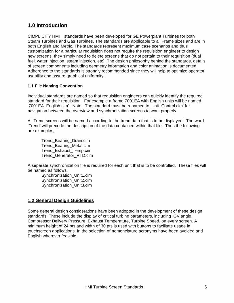
1.0 Introduction
CIMPLICITY HMI standards have been developed for GE Powerplant Turbines for bothSteam Turbines and Gas Turbines. The standards are applicable to all Frame sizes and are inboth English and Metric. The standards represent maximum case scenarios and thuscustomization for a particular requisition does not require the requisition engineer to designnew screens, they simply need to delete screens that do not pertain to their requisition (dualfuel, water injection, steam injection, etc). The design philosophy behind the standards, detailsof screen components including geometry information and color animation is documented.Adherence to the standards is strongly recommended since they will help to optimize operatorusability and assure graphical uniformity. 1.1 File Naming Convention
Individual standards are named so that requisition engineers can quickly identify the requiredstandard for their requisition. For example a frame 7001EA with English units will be named‘7001EA_English.cim’. Note: The standard must be renamed to ‘Unit_Control.cim’ fornavigation between the overview and synchronization screens to work properly.
All Trend screens will be named according to the trend data that is to be displayed. The word‘Trend’ will precede the description of the data contained within that file. Thus the followingare examples,
Trend_Bearing_Drain.cimTrend_Bearing_Metal.cimTrend_Exhaust_Temp.cimTrend_Generator_RTD.cim
A separate synchronization file is required for each unit that is to be controlled. These files willbe named as follows.
Synchronization_Unit1.cimSynchronization_Unit2.cimSynchronization_Unit3.cim
1.2 General Design Guidelines
Some general design considerations have been adopted in the development of these designstandards. These include the display of critical turbine parameters, including IGV angle,Compressor Delivery Pressure, Exhaust Temperature, Turbine Speed, on every screen. Aminimum height of 24 pts and width of 30 pts is used with buttons to facilitate usage intouchscreen applications. In the selection of nomenclature acronyms have been avoided andEnglish wherever feasible.

HMI Turbine Screen Standards 6

HMI Turbine Screen Standards 7
2.0 Design Philosophy, Functional Grouping and Object Naming
2.1 Interface FoundationLevel 0:
Level 1: Each turbine unit has a single pushbutton used to assign the UNIT,UNIT_NAME and UNIT_NO screen variables. All points within theUnit_Control.cim file (i.e., L1START, L4) are proceeded by the screenvariable ‘UNIT’(Unit_L1START, Unit_L4, Unit_L4T). Thus the L1 buttonsare used to navigate from Unit1 Control to Unit2 Control and the sameCIMPLICITY file may be used.
This functionality simplifies revision control on multi-unit interfaces. TheUNIT variable is assigned values such as ‘T1_’, ‘T2_’… for gas or ‘S1_’,‘S2_’… for steam, depending on the number of units. Thus, when Unit3Control is selected, the variable ‘Unit’ is assigned. The UNIT_NAMEvariable is displayed in the upper right hand corner on the turbinebanner. The UNIT_NO variable is used to assign object visibility’s tobuttons like ‘Tools’ or GT# Synch.
Gas Turbine 2
Gas Turbine 4
Gas Turbine 3
Gas Turbine 1
Overview
!Alarms
ToolsToolsToolsTools
When procedures access files separate from the Unit_Control.cim file,L0procedures are used.
Sometimes buttons are stacked upon on another and the UNIT_NOscreen variable is used to set the buttons visibility. This feature allowsunit specific procedures to be linked to what appears to be a singlebutton.
synch
demand
gt1 synch gt2 synch gt3 synch gt4 synch
gt1 demand gt2 demand gt3 demand gt4 demand

HMI Turbine Screen Standards 8
Level 2:The second grouped of buttons on the right side of the Unit_Controlscreen are used for function mode navigation. Functionally thesebuttons break the DATA_CTRL frame containers navigation up into thefollowing four groups; Control, Monitoring, Auxiliary and Tests.
When one of these buttons is depressed the last set of buttons actuallythe NAV_CTRL frame container display will be affected. Mouse up set’sthe NAV_CTRL screen variable and allows access to all Control options,Monitoring Options, Auxiliary Options or Test Options.
The procedures for this level of navigation are preceded by L2, thus,allowing functional grouping of all navigation procedures (i.e., L1, L2 andL3).
Additionally, the last user selected control option, monitoring option,auxiliary option or test option is maintained in memory. Thus allowingthe user the option of toggling between a certain control screen(ex. DLN2.6) and a particular monitoring screen(ex. Exhaust Temps) bydepressing the level 2 navigation buttons (control/monitoring).
Monitor
Aux
Control
Tests

HMI Turbine Screen Standards 9
Level 3:
Screen File Names
The final set of navigation buttons (colored 170, 170, 170) are used foractual frame to frame navigation. The Level 3 options(button lists) aredisplayed using a frame container called NAV_CTRL and are set to anumber between 1 and 4 corresponding with the value for Control,Monitoring, Ax or Tests..
These buttons assign the variable ‘DATA_CTRL’ and allow navigation toall the control, monitoring, aux. and test frames(currently 26 possibleframes). The Data control frames are named according to the Level 3buttons that are used to get to these frames. For example, the ‘motors’button will take you to the ‘motors’ frame and the ‘trips’ button will takeyou to the ‘trips’ frame.
All standards are max case scenarios. Standards are available for allframe sizes in either English or metric. Thus customization for aparticular requisition does not require the requisition engineer to designnew screens, they simply need to delete screens or frames that do notpertain to their requisition(dual fuel, water injection, steam injection, etc).Standards are named so that requisition engineers can quickly identify
start-up
motors
gen/exciter
dln
liquid fuel
steam power aug
FSR control
IGV Control
water injection
gt1 synchgt2 synchgt3 synchgt4 synch
Control Monitor
exhaust
wheelspace
seismic vibration
bearing temps
generator rtd
proximeter vibe
hydrogen
Aux
flame
start check
timers
trip diagram
gen capability
static start
demanddemanddemanddemand
Tests
overspeed test
shaft voltage
contacts

HMI Turbine Screen Standards 10
Procedures Procedures have been named to foster functional grouping. All alarmbutton actions are named using Alarm_. All navigation proceduresare named with a L0_, L1_, L2_ or L3_. All controller functions arenamed using Ctrl_. All motor control functions are named Motor_.

HMI Turbine Screen Standards 11

HMI Turbine Screen Standards 12
Scripts Scripts are used to accomplish tasks that cannot easily beaccomplished using available CIMPLICITY functionality. Scripts arewritten using visual basic.
Scripts can attached to single objects, grouped objects or simplyadhered to the foundation screen. Most scripts are adhered to thefoundation screen. Consult the CIMPLICITY Base Manual for moreinformation on editing or creating your own scripts.

HMI Turbine Screen Standards 13

HMI Turbine Screen Standards 14

HMI Turbine Screen Standards 15

HMI Turbine Screen Standards 16

HMI Turbine Screen Standards 17
Variables Variables are used to accomplish many different types of functions.
Variables can attached to single objects, grouped objects or simplyadhered to the foundation screen. Consult the CIMPLICITY BaseManual for more information on editing or creating your own variables.

HMI Turbine Screen Standards 18
DATA_CTRL
LAST_AUX_FRAMELAST_MON_FRAMELAST_TEST_FRAMELAST_CTRL_FRAME
These variables are used in conjunction with the SetLastFrame scriptand function to set the appropriate last frame screen variable to thevalue of the data control screen variable(DATA_CTRL). This allows theL2 navigation buttons to remember which control, monitoring, auxiliaryor test frame was visited last. Enabling one button navigation from thecontrol, monitoring, auxiliary and test buttons.
The initial value of these variables can be set so that a favorite control,monitoring, auxiliary or test data control screen can be seen at the firstdepression of the navigation control buttons. However, last defaults tothe first screen control, monitoring, auxiliary or test screen set.
This variable controls the frame position of the DATA_CTRL(datacontrol) frame container. The data control frame container has twenty-six positions and contains all the control, monitoring, auxiliary and testscreens. The value data control variable is set by L3 proceduralfunctions.

HMI Turbine Screen Standards 19
NAV_CTRL
POPUP
This variable controls the frame position of the NAV_CTRL(navigationcontrol) frame container. The navigation control frame container hasfour positions and contains all the buttons for accessing control,monitoring, auxiliary and test screens. The value of the navigationcontrol variable is set by L2 procedural functions.
The POPUP variable is used in conjunction with a screen hot spot toaccess data about or control for certain motors, pumps and valves.When a screen is opened POPUP is initialized at a value of zero.Every popup is grouped and the group’s visibility is set using thecontrol animation tab and the POPUP variables value. Thus only onepopup object can be displayed at any one time.
A X button in the upper right hand corner is used to set POPUP tozero and close the currently viewed popup object.
Data Popup Object Example
### ##
Speed Ratio ValveReference
Feedback ###
X
Monitor
Aux
Control
Tests

HMI Turbine Screen Standards 20
SHOW_POINT_ID The SHOW_POINT_ID screen variable is used with a single button totoggle from a data’s text description to the GE Point ID. Thisfunctionality is sited for the GEPPETTO’s next revision.
#####
#####.##
###
##.###.#
CPDIGV
SpeedMax Vibe
Exhaust
WattsVars
#######
##########
#####
#####.##
###
##.###.#
CPDCSGV
TNH_RPMBB_MAX
TTXM
DWATTDVAR
#######
##########

HMI Turbine Screen Standards 21
3.0 7FA Design Standards
A listing of the frames for a maximum case 7F machine are shown in the attached table. TheLevel 3 Procedure Names, associated Data_Ctrl Values which identify the order of the framesin the frame container are specified. In addition whether the screen frame is a requirement oroptional depending on the requisition and the Navigation Control/ Classification for a maximumcase 7F machine are provided.
In a case where the optional frame is not required it will be necessary to perform the followingsteps1) Open the main frame container, go to the required frame and delete the required frame
using the delete button on the left-hand side of the screen.2) Modify the LAST_CTRL_FRAME, LAST_MON_FRAME, LAST_AUX_FRAME or
LAST_TEST_FRAME variable to reflect the reduced number of frames. The variablesmaybe located by closing the main frame container and under edit in the main toolbarselecting properties and the variable tab.
3) Delete the button associated with the deleted frame (Note: the buttons are in their ownframe container.)
Procedure DATA_CTRL
NAV_CTRL Classification Frame Name
Name Value Required Control Monitoring Aux. TestsL3_Startup 1 Yes 1 Frame_7F_StartupL3_DLN26 2 Optional 1 Frame_DLN26L3_FSR_Ctrl 3 Yes 1 Frame_FSRControlL3_Gen_Exc 4 Yes 1 Frame_7F_GeneratorEX2
KL3_IGV_Ctrl 5 Yes 1 Frame_IGVControlL3_Liquid 6 Optional 1 Frame_7F_LiquidFuelL3_Motors 7 Yes 1 Frame_7F_MotorsL3_SteamPA 8 Optional 1 Frame_7F_SteamL3_Water_Inj 9 Optional 1 Frame_7F_WaterInjectionL3_Brg_Tmps 10 Yes 1 Bar_7F_BearingTemps.ci
mL3_Exhaust 11 Yes 1 Bar_7F_ExhaustTempL3_Gen_RTD 12 Yes 1 Bar_7F_GeneratorRTDL3_Hydrogen 13 Yes 1 Frame_Hydrogen PurityL3_VibProx 14 Optional 1 Bar_7F_Proximeter.cimL3_VibSeism 15 Yes 1 Bar_7F_Seismic.cimL3_Wheelspc 16 Yes 1 Bar_7F_WheelspaceL3_Flame 17 Yes 1 Bar_7F_Flame TempL3_Gen_Cap 18 Optional 1 Frame_7F_Gen_CapL3_StartCk 19 Yes 1 Frame_7F_StartChecksL3_StaticStrt 20 Optional 1 Frame_StaticStartL3_Timers 21 Yes 1 Frame_TimersCountersL3_Trips 22 Yes 1 Frame_7F_TripsL3_IO_Check 23 Yes 1 Frame_7F_IO_CheckL3_OS_Test 24 Yes 1 Frame_Overspeed3600L3_ShaftMon 25 Optional 1 Frame_ShaftVoltMon
Totals 9 7 6 3

HMI Turbine Screen Standards 22
3.1 Object Grouping and Naming
The grouping of objects has been carried out at multiple levels. At the lowest level similarobjects were grouped and at the highest level all the objects in a single frame were grouped(excluding the objects in the Frame Foundation). This method was found to be the optimum inboth the construction and modification of objects.
Note: If an object is ungrouped then the name of the object will be automatically deleted.
Example of Object Grouping and Naming
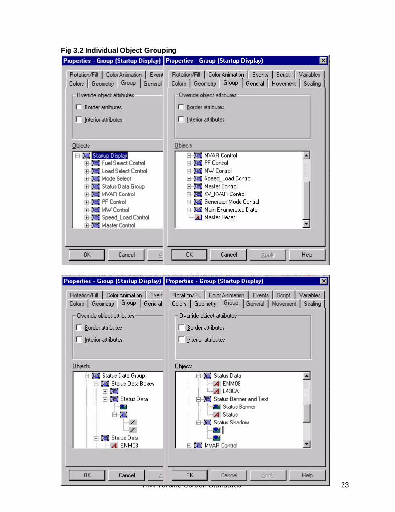
Figure 3.1: Startup Screen Grouping
The objects which form the Start up Screen are shown in Fig: 3.1. All the objects in thescreen are grouped at the highest level and are labeled “Startup Display”. The next levelof grouping is at the individual object level as shown in Fig: 3.2. The individual objectsare then sub-grouped into like objects. In the example the Status Data Group is madeup of the Status Data Boxes, Status Data, Status Banner/ Text and Status Shadow. Thenaming of objects has been performed at all levels as an aid to understanding.
HMI Turbine Screen Standards 23
Fig 3.2 Individual Object Grouping

HMI Turbine Screen Standards 24
4.0 General Object Properties
4.1 General Foundation Screen
The general foundation screen comprises the Title Bar, RHS Navigation buttons and the AlarmWindow.
The title bar will contain:
General ScreenCharacteristics
Background Colors SilverScreen Size 800x600Color Depth At least 65,000 colorsDefault Fonts Text: 12 pt Arial(Regular)Data: 12 pt Lucida SansUnicode (Regular) “LSU”
GE Logo Font Font Color - WhiteGE Logo Font, Regular 22Position 605.5, 5.85
BackgroundGeometry Width – 800 pt
Height – 25 pt Color Gradient Shading
Shade Style – Diagonal UpColor 1 – 66, 65, 66Color 2 - White
Customer Name Font Arial Bold, 20 Color – White (Capital Case),
Position 604, 40
To obtain a 3D effect a carbon copy of name issuperimposed on the original with a slight offset.
ControllerTime & Date
Font Black, Arial Bold, 12
Status Banner Geometry Width – 150 ptHeight – 25 pt
Color Animated GT1 – color 248,193,111with Unit name GT2 – color 147,156,61
GT3 – color 0,195,198 GT2 – color 56,192,114
Position, 600, 650Alignment, Top/Left

HMI Turbine Screen Standards 25
4.2 Navigational Buttons
The functionality of the navigational buttons is described in detail in Section 2.0. The buttonsare physically located on the right hand side of each screen.
start-up
motors
gen/exciter
dln
liquid fuel
steam power aug
FSR control
IGV Control
water injection
Control Monitor
exhaust
wheelspace
seismic vibration
bearing temps
generator rtd
proximeter vibe
hydrogen
Aux
flame
start check
timers
trip diagram
gen capability
static start
demanddemanddemanddemand
Tests
overspeed test
shaft voltage
contacts
Unit Name Font White, Arial Bold Italic, 14 pt
Data_Ctrl Value Font Font Anchor Position, 599.9, 767.45 Arial Italic, 12 pt Alignment, Top/Left
Anchor Position, 590.25, 652.55
Geometry Width – 100 ptHeight – 24 pt
Text Black, Arial Regular 12
(Exception Alarm Height - 63.9 pt Button Text White, Arial Bold 12 Exclamation Mark White, Arial Bold 48)
Colors Overview 108,163,160 Gas Turbine 1 243,193,111Gas Turbine 2 147,156,61Gas Turbine 3 0,195,198Gas Turbine 4 56,192,114Tools 198,195,0Alarms 255,0,0 (Red)Control, Monitor 0,128,128 (Teal)Aux, TestsFrame Navigation 170,170,170
Buttons
Gas Turbine 2
Gas Turbine 4
Gas Turbine 3
Gas Turbine 1
Overview
!Alarms
ToolsToolsToolsTools

HMI Turbine Screen Standards 26
4.3 Alarms
Alarms allow for 4 priority classifications distinguished by the implemented color scheme.
4.4 Trend Screens
Ack/UnAck Normal/Alarm Text/BackgroundUnacknowledged Alarm White/RedUnacknowledged Normal Black/WhiteAcknowledged Alarm Red/WhiteAcknowledged Normal Auto Reset
Trend Screens are associated with Bar Graphs and are opened by buttonactions located on individual Bar Graph screens. CIMPLICITY Trending canonly be accomplished in a real time mode. Thus, trend screens must be opento continue trending.
Geometry, Width – 90 pts, Height – 30 pts.Color 66, 65, 66Font Black, Arial 10 pt
Trend screens, comprise of the title bar, trend options and time intervalselections for which trend is required. The title bar is similar to the mainscreen title bar with the addition of the screen title.
Buttons
General ScreenCharacteristics
Background Colors Silver for Button Area,Gray for Chart Area &Time Interval Area
Screen Size 800x600Color Depth At least 65,000

HMI Turbine Screen Standards 27
GE Logo Font Font Color - WhiteGE Logo Font, Regular 22Position 605.5, 5.85
BackgroundGeometry Width – 800 pt
Height – 25 pt Color Gradient Shading
Shade Style – Diagonal UpColor 1 – 66, 65, 66Color 2 - White
Customer Name Font Arial Bold, 20 Color – White (Capital
Case),Position 604, 40
To obtain a 3D effect a carbon copy of name issuperimposed on the original with a slight offset.
Font Black, Arial Bold, 12
Status Banner Geometry Width – 150 ptHeight – 25 pt
Color Animate GT1 – color 248,193,111with Unit GT2 – color 147,156,61
GT3 – color 0,195,198 GT4 – color 56,192,114
Position, 600, 650Alignment, Top/Left
Unit Name Font White, Arial Bold Italic, 14 pt
Data_Ctrl Value Font Anchor Position, 599.9, 767.45 Arial Italic, 12 pt Alignment, Top/Left
Anchor Position, 590.25, 652.55
Trend Options Trend Options are selectable by buttons, identified by pointdescription. Individual Buttons are available to select Var/Watts/ Speed; all point descriptions, maximum point value,clear display, show legend and hide legend.

HMI Turbine Screen Standards 28
y Var, Watts, SpeedButton
Geometry – Height 24 pts, Width 120 ptsColor - Silver
Point DescriptionButtons
Geometry – Height 24 pts, Width 90 ptsColor – SilverText, Black, Arial Regular 11
Point DescriptionHeader Text, Black, Arial Regular 11
Alignment Left/Top
Time Interval The time intervals currently available for TrendCharts are 24hr, 5hr, 60min, 30min, 10min,5min and 1min. These intervals maybe modifiedby the requisition engineer as required.
Time IntervalButtons Geometry – Height 30 pts, Width 50 pts
Button Color, SilverText, Black, Arial Regular12
Trend Chart Example

HMI Turbine Screen Standards 29
5.0 Data Delivery & Active Control Object Types
Data Delivery &Active ControlObject Types
Data Data feedback using point ID.Text Color - BlackNumeric Data using Lucida Sans Unicode 11pt, with aright/center anchorText using Arial 11pt, with left center text anchor.
Enumerated State Text Data Numerical Data
Data Groups, Enumerated Data Groups, Control Groups, SetpointControl Groups, Motor Control Groups and Bar Graph Groupscomprise the majority of data delivery and active control objecttypes.
Data_Boxes Height - 16 pts in heightWidths divisible by 10 pts.Fill Color – Light Gray (231, 227, 231)Two white lines placed on the bottom and on the right are usedto provide a shadowed look to this object. These boxes arevertically aligned and spaced 3 pts apart. Text is bottomaligned in the databox
Banner Teal box. Text descriptions are grouped and centered on thebanner.
StartingAccelerating
3456789
Data Group Specifics Data Groups are divided into five lesser groups.

HMI Turbine Screen Standards 30
Turbine State
Turbine Status
SpeedExhaust
* Turbine Status is a Enumerated Description using the Controllers enumerated state variable NORMAL.

HMI Turbine Screen Standards 31
Data Group Example
CPDIGV
SpeedMax Vibe
Exhaust
WattsVars
#####
#####.##
###
##.###.#
#######
##########
Shadow Two boxes encompassing all data being displayed. One black, onewhite, slightly offset to provide a shadowed look appearance.
EU_Label Engineering units label,Text Color - Black, Arial 11pt, left/center anchor.
rpmdeg F

HMI Turbine Screen Standards 32
.
Banner encompasses the control objects titleText Color - White, Arial 12pt
Teal box background for text contrast
Buttons Text Color - Black, Arial 12pt, text.Geometry of 70 wide(or divisible by 10) and 24 high.
Title case is used for text. Buttons are aligned and vertically spaced 0 pts apart.
Shadow Two boxes encompassing all data being displayed. One black, onewhite, slightly offset to provide a shadowed look appearance.
Control Group Specifics Control groups objects are divided into three major groups; thebanner, the buttons and the shadow Data Groups are dividedinto five lesser groups.
LoadSelect
Preselect Ld
Base Load
Peak Load

HMI Turbine Screen Standards 33
Control Group Example
LoadSelect
Preselect Ld
Base Load
Peak Load
Setpoint Group Specifics Setpoint group objects are divided into five major groups; DataBoxes, Data Text and Banner, Data, Units and the Shadow
Data_Boxes Height - 16 ptsWidths divisible by 10 pts.Two white lines placed on the bottom and on the right are usedto provide a shadowed look to this object. These boxes arevertically aligned and spaced 3 pts apart. Text is bottom alignedin the box

HMI Turbine Screen Standards 34
Data Text & Banner Text Color – White, Arial 11pt, right/ center anchor.The Banner is a Teal Box. The text descriptions are groupedand centered on the banner.Header Text - Black text, Arial 12 pt, left/ top anchor is placedabove Banner.
IGV Angle
Reference
Setpoint
IGV Mode Control
50.053.053.0
Data Data feedback using point ID.Text Color - Black, Numerical using Lucida Sans Unicode 11pt, witha right/center anchor and Text using Arial 11pt, with left center textanchor.
EU_Label Engineering units labelText Color - Black, Arial 11pt, left/center anchor.
DGA
DGA
DGA
Shadow Two boxes encompassing all data being displayed. Oneblack, one white, slightly offset to provide a shadowed lookappearance.

HMI Turbine Screen Standards 35
Setpoint Group Example
IGV Angle
Reference
Setpoint
IGV Mode Control
DGA
DGA
DGA
50.053.053.0
Motor Control Group Motor control group objects are divided into four major groups; thebanner, the buttons, status indicators and the shadow box.
Banner Encompasses the control objects title (White, Arial 12pt) and the teal boxbackground for text contrast
Hydraulic Supply Pump Auto Rotate

HMI Turbine Screen Standards 36
Buttons Text Color - Black, Arial 12pt, text.Geometry of 70 pts wide and 24 pts high.Title case is used for text.Buttons are aligned and vertically spaced 0 pts apart.The text on the buttons is color animated and turns yellow when the buttonis in the active state.
Off
On#2 Lead#1 Lead
Off
On#2 Lead#1 Lead
Active Inactive
Status Boxes Text Color – Black, Arial Bold 12 pt centered on the object.Geometry - Height 22 pts, Width - 68 pts wide.Two white lines placed on the top and on the left hand side are used toprovide a raised look to this object. These boxes are vertically left aligned withthe buttons directly above and have their middles aligned with the button tothe right.
RunningRunning
Running Stopped
The boxes and text are color animated
Boxes: Running State, Color Red with center gradientshading of 255, 195, 198
Stopped State, Color 0,195,0 with center gradientshading of198, 255, 198
Text: Running State, Text “Running” with color Lime Stopped State, Text “Stopped” with color Red
Shading
Color Animation

HMI Turbine Screen Standards 37
Motor Control Group Example
Shadow Two boxes encompassing all data being displayed. One black, onewhite, slightly offset to provide a shadowed look appearance.
Off
On#2 Lead#1 Lead
Hydraulic Supply Pump Auto Rotate
Running Running
Enumerated Data GroupSpecifics
Enumerated Data Group objects consist of four objects,Enumerated Data Descriptions, Data Boxes, Data and DataShadow.

HMI Turbine Screen Standards 38
Data Descriptions Text Color - White, Arial 11pt, right/center anchor.The text descriptions are grouped and centered on theTeal Box banner.
Tie Line StatusIGV Control
Fuel Control
Turbine StateControl Mode
Turbine Status
The Turbine Status is an Enumerated Description using theControllers enumerated state variable NORMAL.

HMI Turbine Screen Standards 39
Enumerated Data Boxes Geometry Height - 16 ptsWidth of 130 pts divisible by 10 pts.Two white lines placed on the bottom and on the right are usedto provide a shadowed look to this object. These boxes arevertically aligned and spaced 3 pts apart.
Enumerated Data Text Color – Black, Arial 11pt, with left center textanchor
Sequence In ProgressIGV Full Open
Acceleration LP
StartingManual
Accelerating
Shadow Two boxes encompassing all data being displayed. One black, onewhite, slightly offset to provide a shadowed look appearance.

HMI Turbine Screen Standards 40
Enumerated Group Example
Tie Line StatusIGV Control
Fuel Control
Turbine StateControl Mode
Turbine Status
Sequence In ProgressIGV Full Open
Acceleration LP
StartingManual
Accelerating
HMI Turbine Screen Standards 41
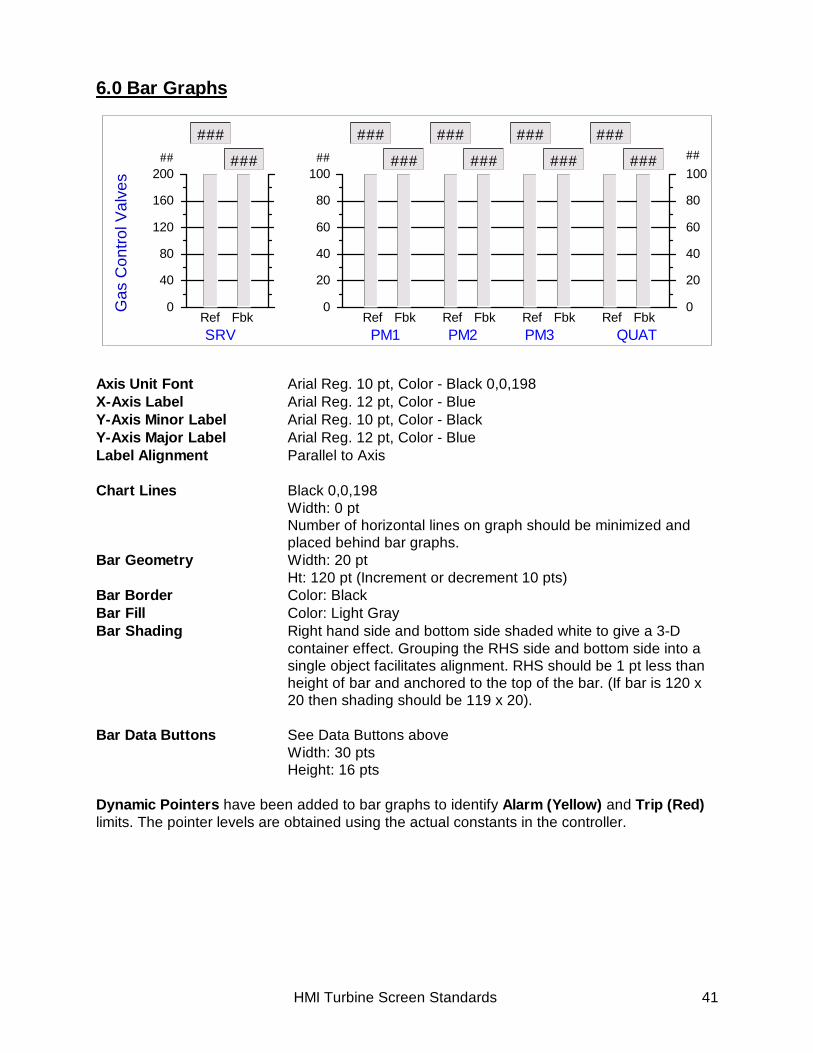
6.0 Bar Graphs
Axis Unit Font Arial Reg. 10 pt, Color - Black 0,0,198X-Axis Label Arial Reg. 12 pt, Color - BlueY-Axis Minor Label Arial Reg. 10 pt, Color - BlackY-Axis Major Label Arial Reg. 12 pt, Color - BlueLabel Alignment Parallel to Axis
Chart Lines Black 0,0,198Width: 0 ptNumber of horizontal lines on graph should be minimized andplaced behind bar graphs.
Bar Geometry Width: 20 ptHt: 120 pt (Increment or decrement 10 pts)
Bar Border Color: BlackBar Fill Color: Light GrayBar Shading Right hand side and bottom side shaded white to give a 3-D
container effect. Grouping the RHS side and bottom side into asingle object facilitates alignment. RHS should be 1 pt less thanheight of bar and anchored to the top of the bar. (If bar is 120 x20 then shading should be 119 x 20).
Bar Data Buttons See Data Buttons aboveWidth: 30 ptsHeight: 16 pts
Dynamic Pointers have been added to bar graphs to identify Alarm (Yellow) and Trip (Red)limits. The pointer levels are obtained using the actual constants in the controller.
## ##
Gas
Con
trol V
alve
s
PM2PM1 QUATPM3SRVRef Fbk
40
20
60
80
100
0
40
20
60
80
100
0Ref Fbk Ref Fbk Ref Fbk Ref Fbk
### ### ### ######### ### ### ########
80
40
120
160
200
0

HMI Turbine Screen Standards 42
6.1 FSR Bar Graph
The color animation for the FSR bar graph is shown in Table 6.1. The range is 0 – 100%
Table 6.1: FSR
Parameter Point Name Normal FillColor
Color AnimationSwitch
Color
FSR T1_FSR 0,195,198 NonSU T1_FSRSU 0,195,198 NonACC T1_FSRCC 0,195,198 T1_L30F_ACN Eq 1
0LimeBlue
SPD T1_FSRN 0,195,198 T1_L30F_ND Eq 1 0
LimeBlue
TEMP T1_FSRT 0,195,198 T1_L30F_TMP Eq 1 0
LimeBlue
SD T1_FSRSD 0,195,198 T1_L30F_SD Eq 1 0
LimeBlue
MAN T1_FSRMAN 0,195,198 T1_L30F_MAN Eq 1 0
LimeBlue
HMI Turbine Screen Standards 43
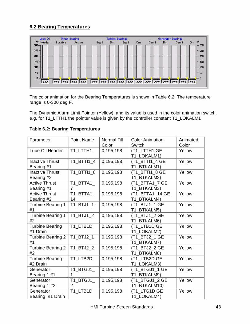
6.2 Bearing Temperatures
The color animation for the Bearing Temperatures is shown in Table 6.2. The temperaturerange is 0-300 deg F.
The Dynamic Alarm Limit Pointer (Yellow), and its value is used in the color animation switch.e.g. for T1_LTTH1 the pointer value is given by the controller constant T1_LOKALM1
Table 6.2: Bearing Temperatures
Parameter Point Name Normal FillColor
Color AnimationSwitch
AnimatedColor
Lube Oil Header T1_LTTH1 0,195,198 (T1_LTTH1 GET1_LOKALM1)
Yellow
Inactive ThrustBearing #1
T1_BTTI1_4 0,195,198 (T1_BTTI1_4 GET1_BTKALM1)
Yellow
Inactive ThrustBearing #2
T1_BTTI1_8 0,195,198 (T1_BTTI1_8 GET1_BTKALM2)
Yellow
Active ThrustBearing #1
T1_BTTA1_7
0,195,198 (T1_BTTA1_7 GET1_BTKALM3)
Yellow
Active ThrustBearing #2
T1_BTTA1_14
0,195,198 (T1_BTTA1_14 GET1_BTKALM4)
Yellow
Turbine Bearing 1#1
T1_BTJ1_1 0,195,198 (T1_BTJ1_1 GET1_BTKALM5)
Yellow
Turbine Bearing 1#2
T1_BTJ1_2 0,195,198 (T1_BTJ1_2 GET1_BTKALM6)
Yellow
Turbine Bearing#1 Drain
T1_LTB1D 0,195,198 (T1_LTB1D GET1_LOKALM2)
Yellow
Turbine Bearing 2#1
T1_BTJ2_1 0,195,198 (T1_BTJ2_1 GET1_BTKALM7)
Yellow
Turbine Bearing 2#2
T1_BTJ2_2 0,195,198 (T1_BTJ2_2 GET1_BTKALM8)
Yellow
Turbine Bearing#2 Drain
T1_LTB2D 0,195,198 (T1_LTB2D GET1_LOKALM3)
Yellow
GeneratorBearing 1 #1
T1_BTGJ1_1
0,195,198 (T1_BTGJ1_1 GET1_BTKALM9)
Yellow
GeneratorBearing 1 #2
T1_BTGJ1_2
0,195,198 (T1_BTGJ1_2 GET1_BTKALM10)
Yellow
GeneratorBearing #1 Drain
T1_LTB1D 0,195,198 (T1_LTG1D GET1_LOKALM4)
Yellow

HMI Turbine Screen Standards 44
GeneratorBearing 2 #1
T1_BTGJ2_1
0,195,198 (T1_BTGJ2_1 GET1_BTKALM11)
Yellow
GeneratorBearing 2 #2
T1_BTGJ2_2
0,195,198 (T1_BTGJ2_2 GET1_BTKALM12)
Yellow
GeneratorBearing #1 Drain
T1_LTG2D 0,195,198 (T1_LTG2D GET1_LOKALM5)
Yellow
6.3 Exhaust Temperatures
The color animation for an Exhaust Temperature is shown in Table 6.3. The temperature rangeis 0-1400 deg F. The parameter designation X varies from 1 to 27 depending upon thethermocouple position; the color animation switches and colors are however are the same forall thermocouples.
The red (trip) and yellow (alarm) dynamic pointers in the case of the exhaust tempertures arean indication of approximate alarm and trip limits, actual alarms and trips are generated usingthe mean exhaust temperature. The pointers are set as follows:
Dynamic Alarm Limit – Color Yellow, (T1_TTKOT3 + T1_TTRXB)
Dynamic Trip Limit – Color Red, (T1_TTKOT1 MIN (T1_TTRXB+T1_TTKOT2))
Table 6.3: Exhaust Temperatures
Parameter Point Name Normal FillColor
Color AnimationSwitch
AnimatedColor
Exhaust Temp # X T1_TTXD_X 0,195,198 T1_TTXD1_X GE(T1_TTKOTX +T1_TTRXB)
(T1_TTXD1_X GE(T1_TTRXB +T1_TTKOT2)) OR(T1_TTXD1_X GET1_TTKOT1)
Yellow
Red

HMI Turbine Screen Standards 45
Example:Exhaust Temp # 3 T1_TTXD1_3 GE
(T1_TTKOT3 +T1_TTRXB)
(T1_TTXD1_3 GE(T1_TTRXB +T1_TTKOT2)) OR(T1_TTXD1_3 GET1_TTKOT1)
Yellow
Red
HMI Turbine Screen Standards 46
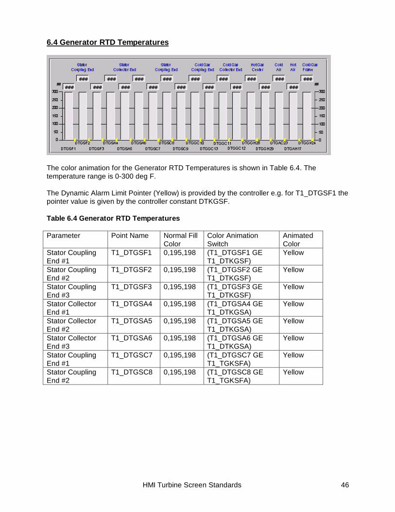
6.4 Generator RTD Temperatures
The color animation for the Generator RTD Temperatures is shown in Table 6.4. Thetemperature range is 0-300 deg F.
The Dynamic Alarm Limit Pointer (Yellow) is provided by the controller e.g. for T1_DTGSF1 thepointer value is given by the controller constant DTKGSF.
Table 6.4 Generator RTD Temperatures
Parameter Point Name Normal FillColor
Color AnimationSwitch
AnimatedColor
Stator CouplingEnd #1
T1_DTGSF1 0,195,198 (T1_DTGSF1 GET1_DTKGSF)
Yellow
Stator CouplingEnd #2
T1_DTGSF2 0,195,198 (T1_DTGSF2 GET1_DTKGSF)
Yellow
Stator CouplingEnd #3
T1_DTGSF3 0,195,198 (T1_DTGSF3 GET1_DTKGSF)
Yellow
Stator CollectorEnd #1
T1_DTGSA4 0,195,198 (T1_DTGSA4 GET1_DTKGSA)
Yellow
Stator CollectorEnd #2
T1_DTGSA5 0,195,198 (T1_DTGSA5 GET1_DTKGSA)
Yellow
Stator CollectorEnd #3
T1_DTGSA6 0,195,198 (T1_DTGSA6 GET1_DTKGSA)
Yellow
Stator CouplingEnd #1
T1_DTGSC7 0,195,198 (T1_DTGSC7 GET1_TGKSFA)
Yellow
Stator CouplingEnd #2
T1_DTGSC8 0,195,198 (T1_DTGSC8 GET1_TGKSFA)
Yellow

HMI Turbine Screen Standards 47
Cold GasCoupling End #1
T1_DTGSC9 0,195,198 (T1_DTGSC9 GET1_TGKSFA)
Yellow
Cold GasCollector End #1
T1_DTGGC10
0,195,198 (T1_DTGGC10 GTT1_TGKGCA)
Yellow
Cold GasCollector End #1
T1_DTGGC13
0,195,198 (T1_DTGGC13 GTT1_TGKGCA)
Yellow
Cold GasCollector End #2
T1_DTGGC11
0,195,198 (T1_DTGGC11 GTT1_TGKGCA)
Yellow
Cold GasCollector End #3
T1_DTGGC12
0,195,198 (T1_DTGGC12 GTT1_TGKGCA)
Yellow
Hot Air CouplingEnd #1
T1_DTGGH28
0,195,198 (T1_DTGGH28 GTT1_TGKGHA)
Yellow
Hot Air CouplingEnd #2
T1_DTGGH29
0,195,198 (T1_DTGGH29 GTT1_TGKGHA)
Yellow
Hot Air CollectorEnd #1
T1_DTGGAC23
0,195,198 (T1_DTGAC23 GET1_TGKGCA)
Yellow
Hot Air CollectorEnd #2
T1_DTGGAH17
0,195,198 (T1_DTGAH17 GET1_TGKGHA)
Yellow
Frame Cold Gas T1_DTGGK24
0,195,198 (T1_DTGGK24 GTT1_DTKGGK)
Yellow

HMI Turbine Screen Standards 48
6.5 Vibration Proximeters
The color animation for the Vibration Proximeters is shown in Table 6.5. The vibration range is0-10 ins/sec.
Table 6.5: Vibration Proximeters
Parameter Point Name Normal Fill ColorAxial Position Z1 T1_TVT96VS1Z1 0,195,198Axial Position Z2 T1_TVT96VS1Z2 0,195,198Turbine Bearings 1X T1_TVT39VS1X 0,195,198Turbine Bearings 1Y T1_TVT39VS1Y 0,195,198Turbine Bearings 2X T1_TVT39VS2X 0,195,198Turbine Bearings 2Y T1_TVT39VS2Y 0,195,198Generator Bearings 3X T1_TVT39VS9X 0,195,198Generator Bearings 3Y T1_TVT39VS9Y 0,195,198Generator Bearings 4X T1_TVT39VS10X 0,195,198Generator Bearings 4Y T1_TVT39VS10Y 0,195,198
HMI Turbine Screen Standards 49
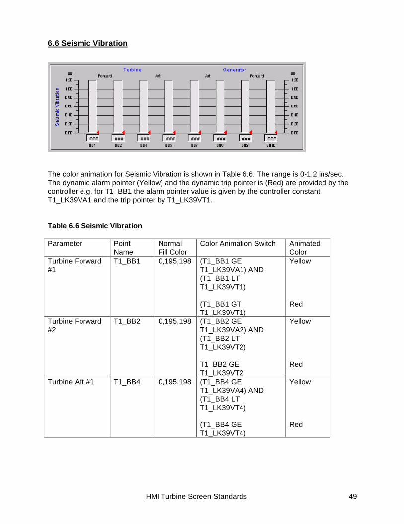
6.6 Seismic Vibration
The color animation for Seismic Vibration is shown in Table 6.6. The range is 0-1.2 ins/sec.The dynamic alarm pointer (Yellow) and the dynamic trip pointer is (Red) are provided by thecontroller e.g. for T1_BB1 the alarm pointer value is given by the controller constantT1_LK39VA1 and the trip pointer by T1_LK39VT1.
Table 6.6 Seismic Vibration
Parameter PointName
NormalFill Color
Color Animation Switch AnimatedColor
Turbine Forward#1
T1_BB1 0,195,198 (T1_BB1 GET1_LK39VA1) AND(T1_BB1 LTT1_LK39VT1)
(T1_BB1 GTT1_LK39VT1)
Yellow
Red
Turbine Forward#2
T1_BB2 0,195,198 (T1_BB2 GET1_LK39VA2) AND(T1_BB2 LTT1_LK39VT2)
T1_BB2 GET1_LK39VT2
Yellow
Red
Turbine Aft #1 T1_BB4 0,195,198 (T1_BB4 GET1_LK39VA4) AND(T1_BB4 LTT1_LK39VT4)
(T1_BB4 GET1_LK39VT4)
Yellow
Red

HMI Turbine Screen Standards 50
Turbine Aft #2 T1_BB5 0,195,198 (T1_BB5 GET1_LK39VA5) AND(T1_BB5 LTT1_LK39VT5)
(T1_BB5 GET1_LK39VT5)
Yellow
Red
Generator Aft #1 T1_BB7 0,195,198 (T1_BB7 GET1_LK39VA7) AND(T1_BB7 LTT1_LK39VT7)
(T1_BB7 GET1_LK39VT7)
Yellow
Red
Generator Aft #2 T1_BB8 0,195,198 (T1_BB8 GET1_LK39VA8) AND(T1_BB8 LTT1_LK39VT8)
(T1_BB8 GET1_LK39VT8)
Yellow
Red
GeneratorForward #1
T1_BB9 0,195,198 (T1_BB9 GET1_LK39VA9) AND(T1_BB9 LTT1_LK39VT9)
(T1_BB9 GET1_LK39VT9)
Yellow
Red
GeneratorForward #2
T1_BB10 0,195,198 (T1_BB10 GET1_LK39VA10) AND(T1_BB10 LTT1_LK39VT10)
(T1_BB10 GET1_LK39VT10)
Yellow
Red

HMI Turbine Screen Standards 51
6.7 Wheelspace Temperatures
The color animation for the Wheelspace Temperatures is shown in Table 6.7. The range is 0-900 deg F.
Table 6.7 Wheelspace Temperatures
Parameter Point Name Normal FillColor
Color AnimationSwitch
AnimatedColor
First StageForward Inner #1
T1_TTWS1FI1
0,195,198 (T1_L3 EQ 1) AND(T1_TTWS1FI1 GET1_WSKALM1)
(T1_L3 EQ 0) AND(T1_TTWS1FI1 GE(T1_WSKALM1+T1_WSKALM9))
Yellow
Yellow
First StageForward Inner #2
T1_TTWS1FI2
0,195,198 (T1_L3 EQ 1) AND(T1_TTWS1FI2 GET1_WSKALM1))
(T1_L3 EQ 0) AND(T1_ TTWS1FI2 GE(T1_WSKALM3+T1_WSKALM9))
Yellow
Yellow
First Stage AftOuter #1
T1_TTWS1AO1
0,195,198 (T1_L3 EQ 1) AND(T1_TTWS1AO1 GET1_WSKALM3)
(T1_L3 EQ 0) AND(T1_TTWS1AO1 GE(T1_WSKALM3+T1_WSKALM9))
Yellow
Yellow
First Stage AftOuter #2
T1_TTWS1AO2
0,195,198 (T1_L3 EQ 1) AND(T1_TTWS2FO1 GET1_WSKALM4)
(T1_L3 EQ 0) AND
Yellow
Yellow

HMI Turbine Screen Standards 52
(T1_TTWS2FO1 GE(T1_WSKALM4+T1_WSKALM9))
Second StageForward Inner #1
T1_TTWS2FO1
0,195,198 (T1_L3 EQ 1) AND(T1_TTWS2FO1 GET1_WSKALM4)
(T1_L3 EQ 0) AND(T1_TTWS2FO1 GE(T1_WSKALM4+T1_WSKALM9))
Yellow
Yellow
Second StageForward Inner #2
T1_TTWS2FO2
0,195,198 (T1_L3 EQ 1) AND(T1_TTWS2FO2 GET1_WSKALM4)
(T1_L3 EQ 0) AND(T1_TTWS2FO2 GE(T1_WSKALM4+T1_WSKALM9))
Yellow
Yellow
Second Stage AftOuter #1
T1_TTWS2AO1
0,195,198 (T1_L3 EQ 1) AND(T1_TTWS2AO1 GET1_WSKALM5)
(T1_L3 EQ 0) AND(T1_TTWS2AO1 GE(T1_WSKALM5+T1_WSKALM9))
Yellow
Yellow
Second Stage AftOuter #2
T1_TTWS2AO2
0,195,198 (T1_L3 EQ 1) AND(T1_TTWS2AO2 GET1_WSKALM5)
(T1_L3 EQ 0) AND(T1_TTWS2AO2 GE(T1_WSKALM5+T1_WSKALM9))
Yellow
Yellow
Third StageForward Inner #1
T1_TTWS3FO1
0,195,198 (T1_L3 EQ 1) AND(T1_TTWS3FO1 GET1_WSKALM6)
(T1_L3 EQ 0) AND(T1_TTWS3FO1 GE(T1_WSKALM6+T1_WSKALM9))
Yellow
Yellow
Third StageForward Inner #2
T1_TTWS3FO2
0,195,198 (T1_L3 EQ 1) AND(T1_TTWS3FO2 GET1_WSKALM6)
(T1_L3 EQ 0) AND(T1_TTWS3FO2 GE(T1_WSKALM6+T1_WSKALM9))
Yellow
Yellow

HMI Turbine Screen Standards 53
Third Stage AftOuter #1
T1_TTWS3AO1
0,195,198 (T1_L3 EQ 1) AND(T1_TTWS3AO1 GET1_WSKALM7)
(T1_L3 EQ 0) AND(T1_TTWS3AO1 GE(T1_WSKALM7+T1_WSKALM9))
Yellow
Yellow
Third Stage AftOuter #2
T1_TTWS3AO2
0,195,198 (T1_L3 EQ 1) AND(T1_TTWS3AO2 GET1_WSKALM7)
(T1_L3 EQ 0) AND(T1_TTWS3AO2 GE(T1_WSKALM7+T1_WSKALM9))
Yellow
Yellow

HMI Turbine Screen Standards 54
6.8 Flame Temperatures
The color animation for the Flame Temperatures is shown in Table 6.8. The range is 1200counts.
Table 6.8 Flame Temperatures
Parameter Point Name Normal FillColor
Color AnimationSwitch
Color
FlameDetector #1
T1_FD_INTENS1
0,195,198 Non
FlameDetector #2
T1_FD_INTENS2
0,195,198 Non
FlameDetector #3
T1_FD_INTENS3
0,195,198 Non
FlameDetector #4
T1_FD_INTENS4
0,195,198 Non

HMI Turbine Screen Standards 55
7.0 Graphic Symbols and Animation Dynamics
All Symbols will change color according to the following. When the color changes the entiresymbol 'fill color' will change unless otherwise specified. Graphic Symbols will be placed in aCimview screen to form a Symbol Library.
7.1 Fuel Lines
Gas Line Color, Olive (128, 128, 0)Width, 2ptsVisibility – IF L83FGI eq 1 or L83FM eq 1
Liquid Line Color, Olive (128, 128, 0)Width, 2ptsVisibility – IF L84TL eq 1 or L84MXT eq 1
Steam Line Color, MaroonWidth, 2pts
Control ValvesGas Line
SRV ValveColor Animation:Inactive – Color Green
Active - RedSRV LineColor Animation:Inactive - Gradient Color1 – Green
Color2 - Lime Active - Gradient Red
(IF FSGR gt 1)
Control ValveColor Animation:Inactive – Color Green
Active - RedControl LineColor Animation:Inactive - Gradient Color1 – Green
Color2 - Lime Active - Gradient Red (IF FSGR gt 1)

HMI Turbine Screen Standards 56
7.2 Gas Turbine
Control ValvesSteam Line
LCV ValveColor Animation:Inactive – Color Green
Active - RedLCV LineColor Animation:Inactive - Gradient Color1 – Green
Color2 - Lime Active - Gradient Red
(IF L33CJ1C eq 0)
The gas turbine graphics have been developed using the BOLTstandard as a template. To the template, Modulating IGV’s, GeneratorBreaker and Bleed Heat have been added.
Gas TurbineGraphics
Color AnimationInactive, Gray (Gradient Shading), VALID LT 1Active, Compressor, Green (Gradient Shading) Combustor, Red (Gradient Shading) Hot Section, Yellow (Gradient shading)
Flame Color Gradient Color1 222,130,0 Color2 Yellow
Control ValvesLiquid Line
LCV ValveColor Animation:Inactive – Color Green
Active - RedLCV LineColor Animation:Inactive - Gradient Color1 – Green
Color2 - Lime Active - Gradient Red
(IF FQROUT gt 1)
Modulating IGV’s External Edge, Black, Width 2 pt Fill Color, Gradient Shading Vertical Color 1, Silver Color 2, White Internal Border Color, 132, 255, 255

HMI Turbine Screen Standards 57
7.3 DLN 2.6 Piping & Valving GraphicThe properties for the DLN 2.6 piping and valving graphic are shown below
Generator Breaker .Color Animation, Breaker Open – Green Breaker Closed – Red
Geometry, Lines, Width 20 pt, Height 0 pt Circles, Diameter 9pt Black Circle, Width 1pt
Buttons, Color, Silver Text Color, Black Font, Arial 11 Geometry, Width, 30 pts, Height 20 pts
Bleed Heat Color Animation Active, Line Color 0, 195, 198, Rectangle Color Red
Inactive, Line Color Black, Rectangle Color Green
Geometry Line, Width 2ptInternal Rectangle, Width 12.5 pt, Height 2.8 ptExternal Rectangle, Width 27.2 pt, Height 6.6 pt

HMI Turbine Screen Standards 58
Piping Color, Gradient Shading Color 1, Olive Color 2, 255, 255, 198
External Border, Black, Width 0 pt
PM1 Valve Control ValveThe control valve consists of series of objects with the followingcolors and geometry.1. Color, Black (Fill) ;Geometry Width 32.3 pts, Height 11.45 pts2. Color, Black (Rectangle); Geometry Width 32.3 pts, Height 11.45pts, Width 0 pts.3. Color, Gradient Shading from Center
Color 1, 234, 190, 15 Color 2, 255, 255, 198 External Border, Black, Width 0 pt
Geometry, Width, 32.25 pt, Height, 11.454. Color, Black (Rectangle); Geometry Width 32.3 pts, Height 11.45pts, Width 0 ptsValve OrificeThe valve orifice consists of a series of objects with the followingcolors and geometry.1. Color, 127,127,127 ; Geometry Width 39 pts, Height 17.95 pts2. Color, 153,153,153 ; Geometry Width 39 pts, Height 16 pts3. Color, 178,178,178 ; Geometry Width 39 pts, Height 12.4 pts4. Color, 204,204,204 ; Geometry Width 39 pts, Height 8.6 pts5. Color, 299,299,299 ; Geometry Width 39 pts, Height 5.95 pts6. Color, White ; Geometry Width 39 pts, Height 2.3 pts7. Gradient Shading ; Geometry Width 39 pts, Height 17.95 pts Color 1, 66, 65, 66 Color 2, WhiteValve StemThe valve orifice consists of a series of objects with the followingcolors and geometry.1. Color, 127,127,127 ; Geometry Width 2.85 pts, Height 11.6 pts2. Color, 178,178,178 ; Geometry Width 2.15 pts, Height 11.6 pts3. Color, 299,299,299 ; Geometry Width 1.5 pts, Height 11.6 pts4. Color, White ; Geometry Width 0.45pts, Height 11.6 pts5. Color, Black ; Geometry Width 0 pts, Height 11.6 pts6. Color, Black ; Geometry Width 0 pts, Height 11.6 ptsFontArial, Bold, 12 pt
The remaining control valves PM2, PM3, the Quaternary Valve, Vent Valve and the SRVvalve are identical in design to the PM1 with the control valve shaded as follows:

HMI Turbine Screen Standards 59
7.4 DLN 2.6 Nozzle Graphic
PM2 Valve Control ValveColor, Gradient Shading from Center
Color 1, 247,27,2 Color 2, White
PM3 Valve Control Valve Color, Gradient Shading from Center
Color 1, 56, 192,114 Color 2, White
Quaternary Valve Control Valve Color, Gradient Shading from Center Color 1, Color 1, 77, 124, 172 Color 2, Color 2, White
Vent & SRV Valves Control ValveColor, Gradient Shading from Center
Color 1, 127, 127, 127 Color 2, White
Outer Circle Geometry, Width 240 pts, Height 240pts.Color, External border, White, Width 0 pts
Fill Color, Gradient Shading from Center Color 1, 66,65,66 Color 2, White

HMI Turbine Screen Standards 60
Quaternary Circle Geometry, Width 220 pts, Height 220pts.Color, External border, White, Width 0 pts
Fill Color, Gradient Shading from Center Color 1, 77, 124, 172 Color 2, 231, 227, 231
Quaternary Animation Geometry, Width 185 pts, Height 185 pts.Color, External border, Black, Width 0.5 pts
Fill Color, Black Color Animation
Fill Color, Red (L30QGCV & L28FDX eq 1)
Inner Circle Geometry, Width 165 pts, Height 165 pts.Color, External border, White, Width 1 pts
Fill Color, Gradient from Center Color Animation
Fill Color, Red (L30QGCV & L28FDX eq 1)
Quaternary Text White, Arial, Regular 12
PM3 On Geometry, Width 50 pts, Height 50 ptsColor, External border, Black, Width 0.5 pts
Fill Color, Black Color Animation
Fill Color, Red (L30PM3_C & L28FDX eq 1)
PM3 Off Geometry, Width 34 pts, Height 34 ptsColor, External border, Black, Width 0.5 pts
Fill Color, Gradient Shading from Center Color 1, 56,192,114
Color 2, 198,255,255Text, Arial 11, Bold, Alignment Center\Center
PM2 On Geometry, Width 50 pts, Height 50 ptsColor, External border, Black, Width 0.5 pts
Fill Color, Black Color Animation
Fill Color, Red (L30PM2_C & L28FDX eq 1)
PM2 Off Geometry, Width 34 pts, Height 34 ptsColor, External border, Black, Width 0.5 pts
Fill Color, Gradient Shading from Center Color 1, 56,192,114
Color 2, 198,255,255Text, Arial 11, Bold, Alignment Center\Center

HMI Turbine Screen Standards 61
PM1 On Geometry, Width 50 pts, Height 50 ptsColor, External border, Black, Width 0.5 pts
Fill Color, Black Color Animation
Fill Color, Red (L30PM1_C & L28FDX eq 1)
PM1 Off Geometry, Width 34 pts, Height 34 ptsColor, External border, Black, Width 0.5 pts
Fill Color, Gradient Shading from Center Color 1, 234, 190, 15
Color 2, 255, 227,198Text, Arial 11, Bold, Alignment Center\Center

HMI Turbine Screen Standards 62
7.5 Exhaust Thermocouple Graphics An Upstream schematic of the Exhaust thermocouples for a 7FA machine is shown below.
Heading Black, Arial, Regular 10, Alignment Left\Top
Point Description Black, Arial, Bold 8, Alignment Center\TopColor Animation Color 1, Navy, L30TXA eq 0 & L86TXT eq 0
Color 2, Yellow, L30TXA eq 1 & L86TXT eq 0 Color 3, Red, L86TXT eq 1
Lines Black, Width 2 pts
Outer Circle Geometry, Width 148 pt, Height 148 ptBlack, Width 2 ptsFill Color, Gradient from CenterSingle Color, Olive
Burners Geometry, Width 17.8 pt, Height 17.8 ptColor 66,65, 66, Width 0.5 ptText, Black, Arial, Bold 14 ptFill Color, Gradient from CenterSingle Color, 66,65,0Color AnimationGradient, L28FDX eq 1 Color 1, 255, 255, 132 Color 2, 255, 130, 0
Inner Circle 1 Geometry, Width 72 pt, Height 72 ptColor Black, Width 2 ptFill Color, PatternColor, TealPattern Color, White

HMI Turbine Screen Standards 63
Inner Circle 2 Geometry, Width 58 pt, Height 58 ptColor Black, Width 2 ptFill Color, Gradient from center Color 1, Gray Color 2, 231, 227, 231
Inner Circle 3 Geometry, Width 25 pt, Height 25 ptColor Black, Width 2 ptFill Color, Gradient Horizontal Color 1, Silver Color 2, White
Center Geometry, Width 14 pt, Height 14 ptColor Black, Width 2 ptFill Color, Pattern Color 1, Maroon Color 2, White

HMI Turbine Screen Standards 64
8.0 Start Check Screen
Start Check 0
Bus UndervoltageL27BN or L27BN
Customer Permissive to StartL3CP
Comp Inlet Thermocouples Disagree L86TCI
Gas Fuel or IGV Control Valve FaultL3VLVFLT
SpareSPARESpare
SPARESpare
SPARE
The Start Check Screen provides a list ofsignals which all must be in the properstate GREEN to permit a start. Therefore,a green signal is required to start the unit.If signals are RED then a start request isinhibited.
NOTREADY TO START
READY TO START
When a RED signal is present thenthe text in the Data Box turns red andthe “NOT READY TO START” signalis displayed. When all signals aregreen then the Data Box displays the“ READY TO START” signal in green.
Start Check Buttons Geometry, Width 220 pts, Height 27 ptsColor Animation Fill Color, Lime L3TCK0 eq 1 Fill Color, Red L3TCK0 eq 0Text, Black, Arial, Bold 11
Data Boxes Geometry, Width 220 pts, Height 27 ptsColor Animation Normal Fill Color, Red Fill Color, LimeText, Black, Arial Regular 12, Alignment Center\ BottomShading, two white lines placed on the bottom and on
the right are used to provide a shadowed look to thisobject. These boxes are vertically aligned and spaced2 pts apart.

HMI Turbine Screen Standards 65
Point Description Point Name NormalColor
Color AnimationSwitch
AnimatedColor
Start Check 0Bus UnderVoltage T1_L27BN Red T1_L27BN Eq 1 or
T1_L27BZ eq 1Lime
Compressor InletThermocouplesDisagree
T1_L86TCI Red T1_L86TCI eq 0 Lime
Gas Fuel or IGV ControlValve Fault
T1_L3VLVFLT Red T1_L3VLVFLT eq 0 Lime
Start Check 1Customer Permissive toStart
T1_L3CP Red T1_L3CP eq 1 Lime
Lube Oil Tank Temp -Normal
T1_L26QN Red T1_L26QN eq 1 Lime
Flame Detector Trouble T1_L28FDSCK Red T1_L28FDSCK eq 1 LimeControl Mode = OFF T1_L430 Red T1_L430 eq 0 LimeHydraulic ProtectiveTrouble
T1_L86HD Red T1_L86HD eq 0 Lime
Generator BreakerClosed
T1_L52GX Red T1_L52GX eq 0 Lime
LCI(Static Start)Ready to Start
T1_L3SS_RS Red T1_L3SS_RS eq 1 Lime
EX2000 Status SExciter Alarm
T1_L30EX_SS Red T1_L30EX_SS eq 0 Lime
Start Check 2 Red LimeCompressor BleedValve or IGV Pos.Lockout
T1_L86CBA Red T1_L86CBA eq 0 Lime
Loss of MasterProtective
T1_L4Y Red T1_L4Y eq 1 Lime
Compressor OperatingLimit BH Start Check
T1_L38BHSTCK Red T1_L38BHSTCKeq 1
Lime
Hydrogen Start Check T1_L3STCK_HGEN
Red T1_L3STCK_HGEN eq1
Lime
Static Starter Shutdown T1_L94SSX Red T1_L94SSX eq 0 LimeStatic Start Inhibitedfrom other unit
T1_L4INHIBIT_ST Red T1_L4INHIBIT_STeq 0
Lime
Master ProtectiveStartup Trip
T1_L86MP Red T1_L86MP eq 0 Lime
Start Check 3Loss of MasterProtective
T1_L4T Red T1_L4T eq 0 Lime
Off-Line Diagnostics T1_L43DIAG Red T1_L43DIAG eq 0 LimeVibration Start Inhibit T1_L39VD3 Red T1_L39VD3 eq 0 LimeLoss of CDP Bias T1_L3TFLT Red T1_L3TFLT eq 0 LimeHP Speed –MinimumFiring Speed
T1_L14HM Red T1_L14HM eq 0 Lime
The start permissives for a maximum case 7FA machine are listed in the table below.

HMI Turbine Screen Standards 66
Start Check AA20AA System StartCheck enable
T1_L3STAA_ENB Red T1_L3STAA_ENB eq 0 Lime
Upstream AA Hi/LoPosition Fault
T1_L30AA1PO_ALM
Red T1_L30AA1PO_ALMeq 0
Lime
20AA PositionFeedback Fault
T1_L30AAFB_ALM
Red T1_L30AAFB_ALM eq0
Lime
Downstream AA Hi/LoPosition Fault
T1_L30AA2PO_ALM
Red T1_L30AA2PO_ALMeq 0
Lime
9.0 Trip Screen
Point Description Point Name NormalColor
Color AnimationSwitch
AnimatedColor
Master Protective TripProtective Status Trip T1_L4PST Lime T1_L4PST eq 1 RedPre-Ignition Trip T1_L4PRET Lime T1_L4PRET eq 0 RedPost-Ignition Trip T1_L4POST Lime T1_L4POST eq 0 RedStarting Device Trip T1_L3SMT Lime T1_L3SMT eq 0 RedInlet Guide VaneControl Trouble Trip
T1_ L4IGVT Lime T1_ L4IGVT eq 0 Red
TCEA 5E/PB CircuitStatus
T1_L5E_TCEA Lime T1_L5E_TCEA eq 0 Red
Protective Check 1Low Lube Oil PressureTrip
T1_L63QTX Lime T1_L63QTX eq 0 Red
Fire Indication Trip T1_L45FTX Lime T1_L45FTX eq 0 RedGenerator DifferentialTrip Lockout
T1_L86TGT Lime T1_L86TGT eq 0 Red
The Trip screen provides a list of Protectivetrips for the 7FA. The trips are normallyGREEN and turn RED when activated.Some signals are not latched, so the datalogger must be checked for an accuratechain of events, leading to any highlightedtrips that may appear on the display.
Master Protective Trip
L4IGVTInlet Guide Vane Control Trouble Trip
L4PRETPre-Ignition Trip
L4POSTPost-Ignition Trip
L4PSTProtective Status Trip
L3SMTStarting Device Trip
TCEA 5E/PB Circuit StatusL5E_TCEA
A list of the protective trips for a maximum case 7FA is shown in the table below.

HMI Turbine Screen Standards 67
TCEA External Trip T1_L4_RLYT Lime T1_L4_RLYT eq 0 RedTransfer Differential TripLockout
T1_L86TT Lime T1_L86TT eq 0 Red
Exhaust Pressure HighTrip
T1_ L63ETH Lime T1_ L63ETH eq 0 Red
Protective Check 2Vibration Trip T1_L39VTRIP Lime T1_L39VTRIP EQ 0 RedStartup Fuel FlowExcessive Trip
T1_L2SFT Lime T1_L2SFT EQ 0 Red
Loss of Protective HPSpeed Inputs
T1_L12H_FLT Lime T1_L12H_FLT EQ 0 Red
Customer Trip Input T1_L4CT Lime T1_L4CT EQ 0 RedProtective Check 3Control Speed SignalLost - HP
T1_L12HF Lime T1_L12HF EQ 0 Red
Protective Speed SignalTrouble
T1_L12HFD Lime T1_L12HFD_P EQ 0 Red
Control Speed SignalTrouble
T1_L12HFD_C Lime T1_L12HFD_C EQ 0 Red
GCV Not FollowingReference Trip
T1_L86GCVT Lime T1_L86GCVT EQ 0 Red
Secondary GCV NotFollowing Ref Trip
T1_L86GCVST Lime T1_L86GCVST EQ 0 Red
Quaternary GCV NotFollowing Ref Trip
T1_L86GCVQT Lime T1_L86GCVQT EQ 0 Red
PM3 GCV Not FollowingReference Trip
T1_L86GCV3T Lime T1_L86GCV3T EQ 0 Red
Protective Check 4Control System FaultTrip
T1_L3SFLT Lime T1_L3SFLT EQ 0 Red
Pre-Ignition TripAuxiliary Check(Servos)
T1_L3ACS Lime T1_L3ACS EQ 1 Red
Pre-Ignition TripAuxiliary Logic
T1_L4PRETX Lime T1_L4PRETX EQ 0 Red
Post-Ignition TripPost Ignition TripAuxiliary
T1_L4POSTX Lime T1_L4POSTX EQ 0 Red
Loss of Flame trip T1_L28FDT Lime T1_L28FDT EQ 0 RedHigh ExhaustTemperature trip
T1_L30SPT Lime T1_L30SPT EQ 0 Red
ExhaustOvertemperature trip
T1_L86TXT Lime T1_L86TXT EQ 0 Red
Compressor BleedValve Pos. Trouble Trip
T1_L86CBT Lime T1_L86CBT EQ 0 Red
Load TunnelTemperature High - Trip
T1_L30LTT Lime T1_L30LTT EQ 0 Red
HMI Turbine Screen Standards 68
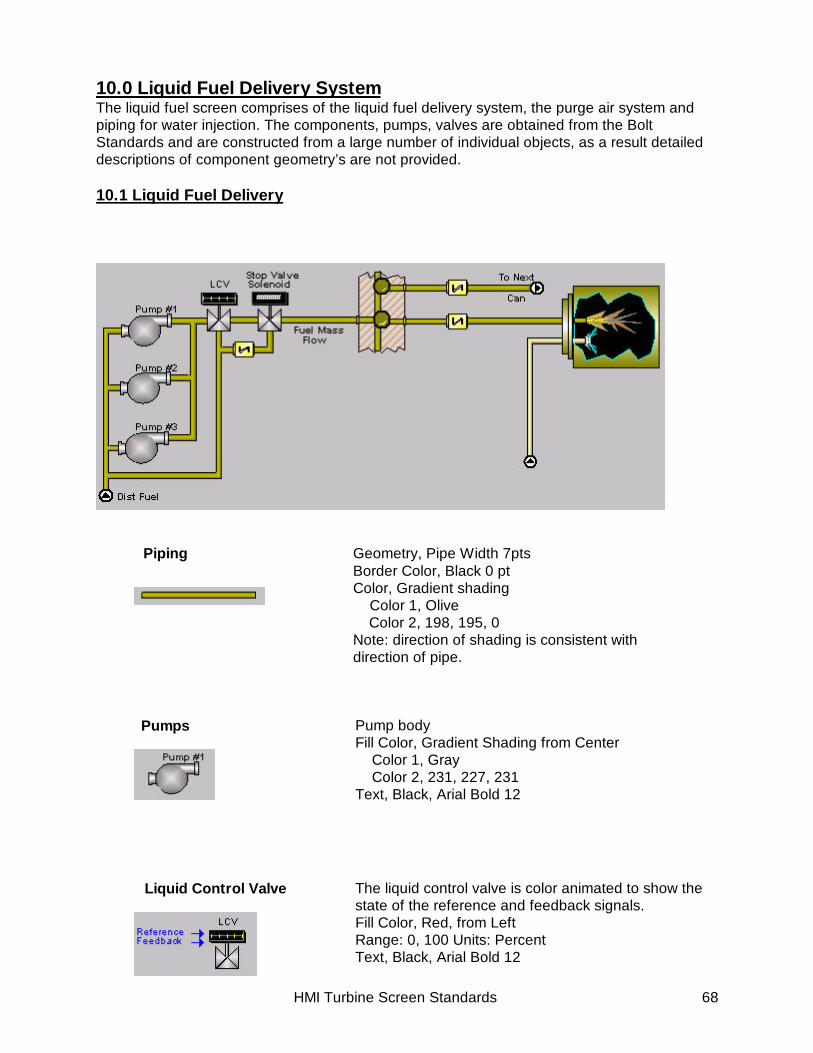
10.0 Liquid Fuel Delivery SystemThe liquid fuel screen comprises of the liquid fuel delivery system, the purge air system andpiping for water injection. The components, pumps, valves are obtained from the BoltStandards and are constructed from a large number of individual objects, as a result detaileddescriptions of component geometry’s are not provided.
10.1 Liquid Fuel Delivery
Piping Geometry, Pipe Width 7ptsBorder Color, Black 0 ptColor, Gradient shading Color 1, Olive
Color 2, 198, 195, 0Note: direction of shading is consistent withdirection of pipe.
Pumps Pump bodyFill Color, Gradient Shading from Center Color 1, Gray Color 2, 231, 227, 231Text, Black, Arial Bold 12
Liquid Control Valve The liquid control valve is color animated to show thestate of the reference and feedback signals.Fill Color, Red, from LeftRange: 0, 100 Units: PercentText, Black, Arial Bold 12

HMI Turbine Screen Standards 69
Stop Valve Solenoid The text in the Stop Valve Solenoid is color animatedText: Valve Open, Text “Open” with color Red Valve Closed,Text “Closed” with color Lime
Check Valve
Round Light
Object Color, Gradient Shading Diagonal Up Color 1, Yellow Color 2, 255, 255, 210
Border Color, Black 2 pts,Geometry, Width 19.6 pts, Height 20 ptsLine Color, WhiteGeometry, Width 8.15 pts, Height 6.25 ptThe object is color animatedObject Color, Olive. Animated Color, Yellow based on {Point_to_Change_Color} variable
Flame External Border, Black 1 PtFill Color, Gradient Horizontal Color 1, Olive Color 2, 255, 255, 198Internal Border, Aqua 1 PtFill Color, Black
Flame, color animatedNormal Color, Black, T1_L28FDX eq 0Animated Color, Gradient, Vertical, T1_L28FDX eq 1 Color 1, 198, 65, 0 Color 2, Yellow
Water Injection, Visibility is set by T1_L30WATERON eq 1.0 Fill Color, Aqua, gradient from center

HMI Turbine Screen Standards 70
10.2 Purge Air System
Piping Geometry, Pipe Width 7ptsBorder Color, Black 0 pt
Color, Gradient shadingColor 1, GreenColor 2, 198, 225, 198
Note: direction of shading is consistent with direction ofpipe.
Purge\ Isolation Valve The text in the Stop Valve Solenoid is color animatedText: Valve Open, Text “Open” with color Red Valve Closed,Text “Closed” with color Lime

HMI Turbine Screen Standards 71
11.0 Water Injection System
The water injection screen comprises of the water injection delivery system and thepurge air system. The components, pumps, valves are obtained from the BoltStandards and are constructed from a large number of individual objects, as a resultdetailed descriptions of component geometry’s are not provided.
Pumps Pump bodyFill Color, Gradient Shading from Center Color 1, Gray Color 2, 231, 227, 231Text, Black, Arial Bold 12
Piping Geometry, Pipe Width 7pts(Water Injection) Border Color, Black 0 pt
Color, Gradient shading Color 1, Olive Color 2, 198, 195, 0
Note: direction of shading is consistent withdirection of pipe.
Check Valve Object Color, Gradient Shading Diagonal Up Color 1, Yellow Color 2, 255, 255, 210
Piping Geometry, Pipe Width 7pts(Purge Air System) Border Color, Black 0 pt
Color, Gradient shading Color 1, Green Color 2, 198, 255, 198
Note: direction of shading is consistent withdirection of pipe.

HMI Turbine Screen Standards 72
Stop Valve\ Isolation Valve The stop valve is color animated for open and closedstatesOpen, Color Red, T1_L33WP1O eq 1Closed, Color 0,195,0 T1_L20WP1C eq 1Text, Black Arial bold 11
Text Text, Black Arial bold 11
Data_Boxes Height - 16 ptsWidths divisible by 10 pts.Two white lines placed on the bottom and on the rightare used to provide a shadowed look to this object.These boxes are vertically aligned and spaced 3 ptsapart. Text is bottom aligned in the box
Data Data feedback using point ID.Text Color - Black, Numerical using Lucida Sans Unicode11pt, with a right/center anchor and Text using Arial 11pt,with left center text anchor.
Water InjectionExternal Border, Black 1 PtFill Color, Gradient Horizontal Color 1, Olive Color 2, 255, 255, 198Internal Border, Aqua 1 PtFill Color, Black
Flames, have four modes of color animationMode 1, T1_L28FDX eq 1 NOT T1_L84TG eq 1 Line, Gray 0.5 pt Fill, Gradient Color 1, Yellow Color 2, 198, 65, 0Mode 2, T1_L28FDX eq 0 orMode 3, T1_L28FDX eq 1 T1_L84TG eq 1 Line, None Fill, NoneMode 4, 1Color 2, Yellow Line, None Fill Color, Yellow

HMI Turbine Screen Standards 73
The components, pumps, valves are obtained from the Bolt Standards and are constructedfrom a large number of individual objects, as a result detailed descriptions of componentgeometry’s are not provided.
12.0 Steam Power Augmentation System
Water Injector The water injector is constructed from 4 individual objectsObject 1, Geometry Width 7.75 pt, Height 6.4 pt Fill Color Black, Gradient to CornerObject 2, Geometry Width 3.9 pt, Height 9.7 pt Fill Color 215, 215, 215 Gradient VerticalObject 3, Geometry Width 7.75 pt, Height 9.7 pt Fill Color 114, 114, 114 Gradient Vertical
Object 4, Geometry Width 7.75 pt, Height 6.4 pt Fill Color 97,97,97, Gradient to Corner
Water Spray The water spray consists of two sets of identical objects.Each object consisting of 4 lines Color Aqua, Width 0.5 ptsGeometry Line 1, Width 18.65 pts, Height 8.7 pts Line 2, Width 17 pts, Height 12.3 pts Line 3, Width 14.75 pts, Height 14.7 pts Line 4, Width 11.15 pts, Height 15.75 pts

HMI Turbine Screen Standards 74
The steam injection schematic shows the steam system, fuel delivery system andpurge air system (in green, not fully shown). The valves are obtained from the BoltStandards and are constructed from a large number of individual objects, as aresult detailed descriptions of component geometries are not provided.
Piping Geometry, Pipe Width 7ptsBorder Color, Black 0 ptColor, Gradient shading Color 1, Red Color 2, 255, 130, 132
Note: direction of shading is consistent with directionof pipe.
Stop ValveHeader Text, Black Arial bold 12The text in the Control Valve is color animatedText: Valve Open, Text “Open” with color Red
Valve Closed,Text “Closed” with color LimeValve is color animated for open and closed statesOpen, Gradient Shading, T1_L33PL2O eq 1 Color 1, Red
Color 2, 255, 227, 198Closed, Gradient Shading, T1_L33PL2O eq 0 Color 1, 0, 195, 0
Color 2, 198, 255, 198
Status Indicator The text in the Status Indicator is color animatedText: Valve Open, Text “Open” with color Red Valve Closed,Text “Closed” with color Lime
Steam Valves Header Text, Black Arial bold 12Control Valve uses Gradient Shading
Color 1, 56, 192, 114Color 2, White
Valve Orifice is color animated for open and closed statesOpen, Gradient Shading, T1_L30PM3_C eq 0 Color 1, Red Color 2, 255, 195, 198Closed, Gradient Shading, T1_L30PM3_C eq 1 Color 1, Green
Color 2, 198, 255, 198

HMI Turbine Screen Standards 75
Steam Injector The Steam injector is identical to the water injector andconstructed from 4 individual objects.Object 1, Geometry Width 7.75 pt, Height 6.4 pt Fill Color Black, Gradient to CornerObject 2, Geometry Width 3.9 pt, Height 9.7 pt Fill Color 215, 215, 215 Gradient VerticalObject 3, Geometry Width 7.75 pt, Height 9.7 pt Fill Color 114, 114, 114 Gradient VerticalObject 4, Geometry Width 7.75 pt, Height 6.4 pt
Fill Color 97,97,97, Gradient to Corner
Steam The steam object consist of 8 lines Color Aqua, Width 0 ptsGeometry Line 1, Width 12.8 pts, Height 13.75 pts Line 2, Width 12.8 pts, Height 11 pts Line 3, Width 12.8 pts, Height 8.25 pts Line 4, Width 12.8 pts, Height 5.5 pts Line 5, Width 12.85 pts, Height 5.5 pts Line 6, Width 12.85 pts, Height 8.25 pts
Line 7, Width 12.85 pts, Height 11 pts Line 8, Width 12.85 pts, Height 13.75 pts

HMI Turbine Screen Standards 76
13.0 Frame Animation

HMI Turbine Screen Standards 77
14.0 Multi-Unit Configuration
14.1 Overview
14.2 Naming Convention
CIMPLICITY design standards are directly applicable to multi-unit applications. A single set ofscreens is used for a multi-unit system using pushbuttons on the Foundation screen fornavigation between units. Data for individual units is obtained is by setting the screenvariables UNIT, UNIT_NAME and UNIT_NO.
In a multi-unit system a CIMPLICITY server can access its own data and can act as a viewerfor a maximum of two other computers. The screen variable LOCAL_PROJECT is used todetermine if the HMI is operating as a server or as a viewer (LOCAL_PROJECT =0 forViewer,LOCAL_PROJECT =1 for Server)
A Remote system can operate as a server or a viewerEach turbine unit has a single pushbutton used to assign the UNIT,UNIT_NAME and UNIT_NO screen variables. All points within theUnit_Control.cim file (i.e., L1START, L4) are proceeded by the screenvariable ‘UNIT’(Unit_L1START, Unit_L4, Unit_L4T). Thus the L1 buttonsare used to navigate from Unit1 Control to Unit2 Control and the sameCIMPLICITY file may be used.
This functionality simplifies revision control on multi-unit interfaces. TheUNIT variable is assigned values such as ‘T1_’, ‘T2_’… for gas or ‘S1_’,‘S2_’… for steam, depending on the number of units. Thus, when Unit3Control is selected, the variable ‘Unit’ is assigned. The UNIT_NAMEvariable is displayed in the upper right hand corner on the turbinebanner. The UNIT_NO variable is used to assign object visibility’s tobuttons like ‘Tools’ or GT# Synch.
Gas Turbine 2
Gas Turbine 4
Gas Turbine 3
Gas Turbine 1
Consider a Multi-Unit system with three servers (SVR1, SVR2, SVR3, a viewer VWR1 ,and a remote viewer. The naming convention is shown in the Table. The Unit Variablesare initialized at start up
Computer Name SVR1 SVR2 SVR3 REM1Project Name SVR1 SVR2 SVR3 REM1Unit Variable \\SVR1\Tn_ \\SVR2\T2_ \\SVR3\T3_ \\REM1\Tn_.For server SVR1 the navigation button Gas Turbine 1 initiates a procedureL1_Gas_Turbine_1 with the associated actions. The variable LOCAL_VARIABLE is setto 1 on SRV1. For the remaining procedures, L1_Gas_Turbine_2 andL1_Gas_Turbine_3 the variable is set to 0 as shown in the example below where n is theunit number.

HMI Turbine Screen Standards 78
For Server SVR1L1_Gas_Turbine_1 – UNIT, \\SVR1\Tn_ UNIT_NAME, “GTn” UNIT_NO,1
LOCAL_PROJECT,1L1_Gas_Turbine_2 – UNIT, \\SVR2\T2_ UNIT_NAME, “GT2” UNIT_NO,2
LOCAL_PROJECT,0L1_Gas_Turbine_3 – UNIT, \\SVR3\T3_ UNIT_NAME, “GT3” UNIT_NO,3
LOCAL_PROJECT,0
For Server SVR2L1_Gas_Turbine_1 – UNIT, \\SVR1\Tn_ UNIT_NAME, “GTn” UNIT_NO,1
LOCAL_PROJECT,0L1_Gas_Turbine_2 – UNIT, \\SVR2\T2_ UNIT_NAME, “GT2” UNIT_NO,2
LOCAL_PROJECT,1L1_Gas_Turbine_3 – UNIT, \\SVR3\T3_ UNIT_NAME, “GT3” UNIT_NO,3
LOCAL_PROJECT,0
For Viewer VWR1, VWR2… .L1_Gas_Turbine_1 – UNIT, \\VWR1\Tn_ UNIT_NAME, “GTn” UNIT_NO,1
LOCAL_PROJECT,0L1_Gas_Turbine_2 – UNIT, \\VWR1\T2_ UNIT_NAME, “GT2” UNIT_NO,2
LOCAL_PROJECT,0L1_Gas_Turbine_3 – UNIT, \\VWR1\T3_ UNIT_NAME,
UNIT_NO,3 LOCAL_PROJECT,0
HMI Turbine Screen Standards 79
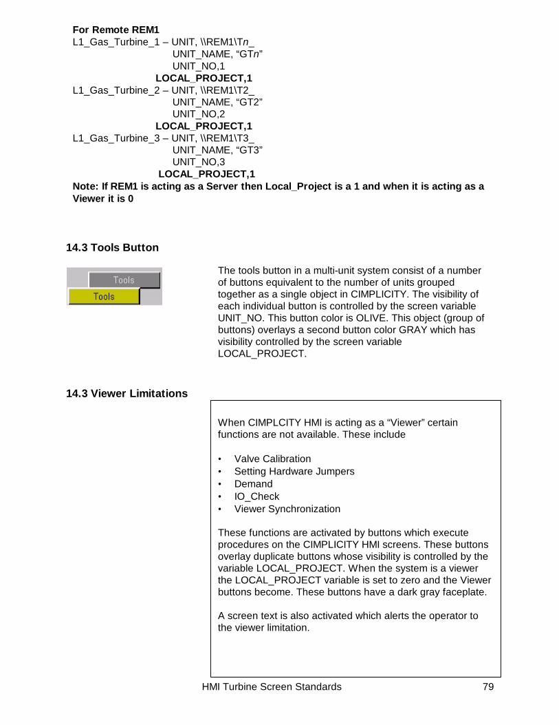
14.3 Tools Button
14.3 Viewer Limitations
For Remote REM1L1_Gas_Turbine_1 – UNIT, \\REM1\Tn_ UNIT_NAME, “GTn” UNIT_NO,1
LOCAL_PROJECT,1L1_Gas_Turbine_2 – UNIT, \\REM1\T2_ UNIT_NAME, “GT2” UNIT_NO,2
LOCAL_PROJECT,1L1_Gas_Turbine_3 – UNIT, \\REM1\T3_ UNIT_NAME, “GT3” UNIT_NO,3
LOCAL_PROJECT,1Note: If REM1 is acting as a Server then Local_Project is a 1 and when it is acting as aViewer it is 0
The tools button in a multi-unit system consist of a numberof buttons equivalent to the number of units groupedtogether as a single object in CIMPLICITY. The visibility ofeach individual button is controlled by the screen variableUNIT_NO. This button color is OLIVE. This object (group ofbuttons) overlays a second button color GRAY which hasvisibility controlled by the screen variableLOCAL_PROJECT.
When CIMPLCITY HMI is acting as a “Viewer” certainfunctions are not available. These include
• Valve Calibration• Setting Hardware Jumpers• Demand• IO_Check• Viewer Synchronization
These functions are activated by buttons which executeprocedures on the CIMPLICITY HMI screens. These buttonsoverlay duplicate buttons whose visibility is controlled by thevariable LOCAL_PROJECT. When the system is a viewerthe LOCAL_PROJECT variable is set to zero and the Viewerbuttons become. These buttons have a dark gray faceplate.
A screen text is also activated which alerts the operator tothe viewer limitation.

HMI Turbine Screen Standards 80
This page intentionally left blank.