¸hms-x spectrum analyzer scpi programmers … commands ¸hms-x remote control 2 scpi programmers...
TRANSCRIPT
¸HMS-XSpectrum AnalyzerSCPI Programmers Manual
SCPI
Pro
gram
mer
s M
anua
l
Test
& M
easu
rem
ent
Vers
ion
02
*5800577602*58005776
SCPI Commands ¸HMS-X Remote Control
2
SCPI Programmers Manual
Content 1 Basics .............................................................................................................................................. 3 1.1 Remote Control Interfaces .............................................................................................................. 3 1.1.1 USB Interface .................................................................................................................................. 3 1.1.2 RS-232 ............................................................................................................................................ 3 1.1.3 GPIB Interface (IEC/IEEE Bus Interface) .......................................................................................... 3 1.1.4 Ethernet (LAN) Interface ................................................................................................................. 4 1.2 Setting Up a Network (LAN) Connection ....................................................................................... 5 1.2.1 Connecting the Instrument to the Network ................................................................................... 5 1.2.2 ConfiguringLANParameters .......................................................................................................... 5 1.3 Switching to Remote Control .......................................................................................................... 6 1.4 Messages and Command Structure ............................................................................................... 7 1.4.1 Messages ........................................................................................................................................ 7 1.4.2 SCPI Command Structure ............................................................................................................... 7 1.5 Command Sequence and Synchronization ................................................................................... 12 1.5.1 Preventing Overlapping Execution ................................................................................................ 13 1.6 Data Formats ................................................................................................................................. 13 1.7 Contents of the Status Registers .................................................................................................. 14
2 Command Reference .................................................................................................................... 17 2.1 Common Commands .................................................................................................................... 17 2.2 General Instrument Setup ............................................................................................................ 20 2.3 TriggerCommands .................................................................................................................23 2.4 Configurationoftheparameters .............................................................................................24 2.4.1 Bandwidthsetting ..................................................................................................................24 2.4.2 Amplitudesetting ...................................................................................................................26 2.4.3 Frequencysetting ...................................................................................................................29 2.4.4 Sweepsetting ........................................................................................................................33 2.4.5 Measurementcommands .......................................................................................................35 2.4.6 Marker Settings ............................................................................................................................. 37 2.4.7 Peak Search commands ............................................................................................................... 40 2.5 BasicDisplaySettings ...........................................................................................................42 2.6 Trace settings ............................................................................................................................... 45 2.7 OutputControl ......................................................................................................................49
3 SCPI Commands (in alphabetic order) .......................................................................................... 50
SCPI Commands ¸HMS-X Remote Control
3
Basics
SCPI Programmers Manual
1 Basics 1.1 Remote Control Interfaces
For remote control, USB or RS-232 interface (¸HO720 - standard interface) can be used. A dual interface Ethernet/USB (¸HO730/HO732) or GPIB interface (¸HO740) are optional available.
SCPI (Standard Commands for Programmable Instruments) SCPI commands - messages - are used for remote control. Commands that are not taken from the SCPI standard follow the SCPI syntax rules.
1.1.1 USB Interface
The ¸HMS-X includes a USB device port. If you are using USB you need to install an USB driver, which can be downloaded free of charge from the Rohde & Schwarz homepage. The traditional version of the VCP allows the user to communicate with the instrument using any terminal program via SCPI commands once the corresponding Windows drivers have been installed. Naturally, the free software “HMExplorer” is also available for the ¸HMS-X. This Windows application offers a terminal function, the option to create screenshots and an EMC software option.
NOTICE The available USB driver is fully tested, functional and released for Windows XP™,
Windows Vista™, Windows 7™, Windows 8™ or Windows 10™, both as 32Bit or 64Bit versions.
The USB interface has to be chosen in the SETUP menu and does not need any setting.
1.1.2 RS-232
If you use RS-232 you do not need any driver. In order to set the RS-232 parameter, please press the SETUP button and choose the soft menu key INTERFACE. Make sure the RS-232 interface is chosen and press the button PARAMETER. In the parameter menu you can set and save all parameterfortheRS-232communication.SettingoftheRS-232mustfitthesettingofthecorre-sponding PC COM Port.
1.1.3 GPIB Interface (IEC/IEEE Bus Interface)
To be able to control the instrument via the GPIB bus, the instrument and the controller have be linked by a GPIB bus cable. A GPIB bus card, the card drivers and the program libraries for the programming language have to be provided in the controller. The controller must address the instrument with the GPIB instrument address.

SCPI Commands ¸HMS-X Remote Control
4
Basics
SCPI Programmers Manual
CharacteristicsThe GPIB interface is described by the following characteristics:• Up to 15 instruments can be connected• The total cable length is restricted to a maximum of 15m; the cable lenth between two
instruments should not exceed 2 meters.• A wired „OR“-connection is used if several instruments are connected in parallel.
GPIB Instrument AddressIn order to operate the instrument via remote control, it has be addressed using the GPIB address. The remote control address is factory-set to 20, but it can be changed in the network environment settings or in the SETUP menu under INTERFACE --> PARAMETER. For remote control, addresses 0 through 30 are allowed. The GPIB address is maintained after a reset of the instrument settings.
1.1.4 Ethernet (LAN) Interface
The settings of the parameter will be done after selecting the menu item ETHERNET and the soft key PARAMETER.YoucansetafixIPadressoradynamicIPsettingviatheDHCPfunction.Please ask your IT department for the correct setting at your network.
IP addressTo set up the connection the IP address of the instrument is required. It is part of the resource string used by the program to identify and control the instrument. The resource string has the form:
TCPIP::‹IP_address›::‹IP_port›::INSTR
The default port number for SCPI socket communication is 5025. IP address and port number are listed in the „Ethernet Settings“ of the ¸HMS-X, see also: chapter1.2.2,“ConfiguringLAN Parameters“.
Example (¸HO732): If the instrument has the IP address 192.1.2.3; the valid resource string is
TCPIP0::192.1.2.3::inst0::INSTR
If the LAN is supported by a DNS server, the host name can be used instead of the IP address. The DNS server (Domain Name System server) translates the host name to the IP address. The resource string has the form:
TCPIP::‹host_name›::‹IP_port›::INSTR
To assign a host name to the instrument, select SETUP button › MISC › DEVICE NAME.
SCPI Commands ¸HMS-X Remote Control
5
Basics
SCPI Programmers Manual
NOTICE The end character must be set to linefeed.
1.2 Setting Up a Network (LAN) Connection
1.2.1 Connecting the Instrument to the Network
NOTICE Risk of network failure
Before connecting the instrument to the network or configuring the network, consult your network administrator. Errors may affect the entire network.
The network card can be operated with a 10 Mbps Ethernet IEEE 802.3 or a 100 Mbps Ethernet IEEE 802.3u interface.
NOTICE To establish a network connection, connect a commercial RJ-45 cable to one of the
LAN ports of the instrument and to a PC.
1.2.2 Configuring LAN Parameters
Depending on the network capacities, the TCP/IP address information for the instrument can beobtainedindifferentways.IfthenetworksupportsdynamicTCP/IPconfigurationusingtheDynamicHostConfigurationProtocol(DHCP),andaDHCPserverisavailable,alladdressinfor-mation can be assigned automatically. Otherwise, the address must be set manually. Automatic Private IP Addressing (APIPA) is not supported.
Bydefault,theinstrumentisconfiguredtousedynamicTCP/IPconfigurationandobtainalladdress information automatically. This means that it is safe to establish a physical connection to theLANwithoutanypreviousinstrumentconfiguration.
NOTICE Risk of network errors Connection errors can affect the entire network. If your network does not support
DHCP, or if you choose to disable dynamic TCP/IP configuration, you must assign valid address information before connecting the instrument to the LAN. Contact your net-work administrator to obtain a valid IP address.

SCPI Commands ¸HMS-X Remote Control
6
Basics
SCPI Programmers Manual
Configuring LAN parameters• Press the SETUP key and then the Interface softkey.• Press the Ethernet and then the Parameter softkey.
NOTICE If the instrument is set to use DHCP and cannot find a DHCP server, it takes about two
minutes until the Ethernet menu is available.
The „Ethernet Settings“ dialog box is displayed.
Some data is displayed for information only and cannot be edited. This includes the „MAC“ (phy-sical) address of the connector and the „Link“ status information.
• DefinetheIPaddressoftheinstrumentbyenteringeachofthefourblocksindividually(ma-nual mode) or choose the automatic IP-Mode. a) Inmanualmode(MAN)definethefirstblocknumberusingtheknob. b) PressNexttomovetothenextblockanddefinethenumber. c) When the IP address is complete, press Down to continue with the next setting.
• Definethe„Subnetmask“and„Gateway“inthesameway.• Select the „IP Port“ - the port number for SCPI socket communication.• Select the „HTTP Port“ used by the instrument.• Select the „Transfer“ mode. This mode can either be determined automatically („Auto“ set-
ting), or you can select a combination of a transfer rate and half or full duplex manually.• Press Save to save the LAN parameters.
NOTICE The „Link“ status information at the bottom of the dialog box indicates whether a LAN
connection was established successfully.
Checking LAN and SCPI connection• Check the LAN connection using ping: ping xxx.yyy.zzz.xxx.• If the PC can access the instrument, enter the IP address of the address line of the internet
browser on your computer: http//:xxx.yyy.zzz.xxx• The „Instrument Home“ page appears. It provides information on the instrument and the LAN
connection.
1.3 Switching to Remote Control
When you switch on the instrument, it is always in manual operation state („local“ state) and can be operated via the front panel. When you send a command from the control computer, it is received and executed by the instrument. The display remains on, manual operation via the front panel is always possible.
SCPI Commands ¸HMS-X Remote Control
7
Basics
SCPI Programmers Manual
1.4 Messages and Command Structure
1.4.1 Messages
Instrument messages are employed in the same way for all interfaces, if not indicated otherwise in the description.See also:• Structure and syntax of the instrument messages: chapter 1.4.2, „SCPI Command Struc-
ture“. Detailed description of all messages: chapter 2, „Command Reference“.
There are different types of instrument messages:• Commands• Instrument responses
CommandsCommands (program messages) are messages which the controller sends to the instrument. They operate the instrument functions and request information. The commands are subdivided according to two criteria:
According to the instrument effect:• Setting commands cause instrument settings such as a reset of the instrument or setting the
frequency. • Queriescausedatatobeprovidedforremotecontrol,e.g.foridentificationoftheinstrument
or polling a parameter value. Queries are formed by appending a question mark to the com-mand header.
According to their definition in standards:• ThefunctionandsyntaxoftheCommoncommandsarepreciselydefinedinstandardIEEE
488.2. They are employed identically on all instruments (if implemented). They refer to func-tions such as management of the standardized status registers, reset and self test.
• Instrument control commands refer to functions depending on the features of the instrument such as voltage settings. Many of these commands have also been standardized by the SCPI committee. These commands are marked as „SCPI compliant“ in the command reference chapters.CommandswithoutthisSCPIlabelaredevice-specific,however,theirsyntaxfollowsSCPI rules as permitted by the standard.
Instrument responsesInstrument responses (response messages and service requests) are messages which the instru-ment is sent to the controller after a query. They can contain measurement results, instrument settings and information on the instrument status.
1.4.2 SCPI Command Structure
SCPI commands consist of a so-called header and, in most cases, one or more parameters. The header and the parameters are separated by a „white space“ (ASCII code 0 to 9, 11 to 32 deci-mal, e.g. blank). The headers may consist of several mnemonics (keywords). Queries are formed by appending a question mark directly to the header.
Thecommandscanbeeitherdevice-specificordevice-independent(commoncommands).Commonanddevice-specificcommandsdifferintheirsyntax.
SCPI Commands ¸HMS-X Remote Control
8
Basics
SCPI Programmers Manual
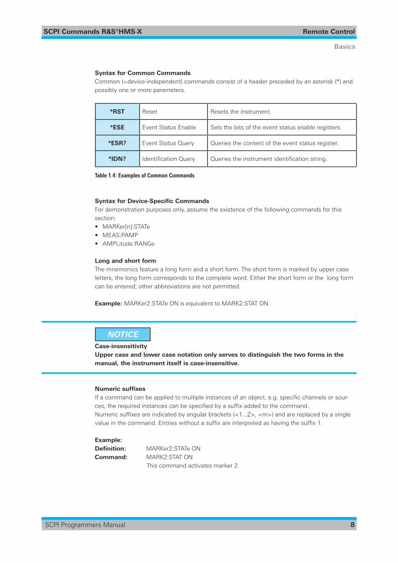
Syntax for Common CommandsCommon (=device-independent) commands consist of a header preceded by an asterisk (*) and possibly one or more parameters.
*RST Reset Resets the instrument.
*ESE Event Status Enable Sets the bits of the event status enable registers.
*ESR? Event Status Query Queries the content of the event status register.
*IDN? IdentificationQuery Queriestheinstrumentidentificationstring.
Table 1.4: Examples of Common Commands
Syntax for Device-Specific CommandsFor demonstration purposes only, assume the existence of the following commands for this section:• MARKer[n]:STATe• MEAS:PAMP• AMPLitude:RANGe
Long and short formThe mnemonics feature a long form and a short form. The short form is marked by upper case letters, the long form corresponds to the complete word. Either the short form or the long form can be entered; other abbreviations are not permitted.
Example: MARKer2:STATe ON is equivalent to MARK2:STAT ON.
NOTICE Case-insensitivity Upper case and lower case notation only serves to distinguish the two forms in the
manual, the instrument itself is case-insensitive.
Numeric suffixesIfacommandcanbeappliedtomultipleinstancesofanobject,e.g.specificchannelsorsour-ces,therequiredinstancescanbespecifiedbyasuffixaddedtothecommand.Numericsuffixesareindicatedbyangularbrackets(<1...2>,<m>)andarereplacedbyasinglevalueinthecommand.Entrieswithoutasuffixareinterpretedashavingthesuffix1.
Example: Definition: MARKer2:STATe ONCommand: MARK2:STAT ON This command activates marker 2.

SCPI Commands ¸HMS-X Remote Control
9
Basics
SCPI Programmers Manual
NOTICE Different numbering in remote control For remote control, the suffix may differ from the number of the corresponding selec-
tion used in manual operation. SCPI prescribes that suffix counting starts with 1. Suffix 1 is the default state and used when no specific suffix is specified.
Optional mnemonicsSome command systems permit certain mnemonics to be inserted into the header or omitted. These mnemonics are marked by square brackets. The instrument must recognize the long command to comply with the SCPI standard. Some commands are shortened by these optional mnemonics.
Example: MARKer[n][:SET]:CENTerMARK2:SET:CENT is equivalent to MARK2:CENT
Special characters
|
Averticalstrokeinparameterdefinitionsindicatesalternativepossibilitiesinthesense of „or“. The effectof the command differs, depending on which parameter is used.
Example:
SYSTem:MODE { SWEep | RMODe }
SYST:MODE RMOD activates the receiver mode.
SYST:MODE SWE activates the sweep mode.
[ ]
Mnemonics in square brackets are optional and may be inserted into the header or omitted.
Example:
MARKer[n][:SET]:CENTer
MARK2:SET:CENT is equivalent to MARK2:CENT.
{ } Parameters in curly brackets are optional.
Table 1.5: Special characters
SCPI Commands ¸HMS-X Remote Control
10
Basics
SCPI Programmers Manual
SCPI ParametersMany commands are supplemented by a parameter or a list of parameters. The parameters must be separated from the header by a „white space“ (ASCII code 0 to 9, 11 to 32 decimal, e.g. blank). Allowed parameters are:
• Numeric values• Special numeric values• Boolean parameters• Text• Character strings• Block data
Theparametersrequiredforeachcommandandtheallowedrangeofvaluesarespecifiedinthecommand description.
Numeric valuesNumeric values can be entered in any form, i.e. with sign, decimal point and exponent. Values exceeding the resolution of the instrument are rounded up or down. The mantissa may com-prise up to 255 characters, the exponent must lie inside the value range -32000 to 32000. The exponent is introduced by an „E“ or „e“. Entry of the exponent alone is not allowed. In the case ofphysicalquantities,theunitcanbeentered.AllowedunitprefixesareG(giga),MA(mega),MOHM and MHZ are also allowed), K (kilo), M (milli), U (micro) and N (nano). If the unit is mis-sing, the basic unit is used.
Example: BANDwidth:RBW 1000000 = BAND:RBW 1e6
UnitsForphysicalquantities,theunitcanbeentered.Allowedunitprefixesare:• G (giga)• M (mega)• K (kilo)• M (milli)• U (micro)• N (nano)
If the unit is missing, the basic unit is used.
Special numeric valuesThe texts listed below are interpreted as special numeric values. In the case of a query, the nu-meric value is provided.• MIN / MAX• MINimum and MAXimum denote the minimum and maximum value
Example:FREQ:CENT MAXFREQ:CENT MAX?, Response: 3.000000E+09 (with installed 3GHz option)

SCPI Commands ¸HMS-X Remote Control
11
Basics
SCPI Programmers Manual
Boolean ParametersBoolean parameters represent two states. The „ON“ state (logically true) is represented by „ON“ or a numeric value 1. The „OFF“ state (logically untrue) is represented by „OFF“ or the numeric value 0. The numeric values are provided as the response for a query.
Example:MARK1:STATe ONMARK1:STAT?, Response: ON
Text parametersText parameters observe the syntactic rules for mnemonics, i.e. they can be entered using a short or long form. Like any parameter, they have to be separated from the header by a white space. In the case of a query, the short form of the text is provided.
Example: SWEep:MODE SINGSWE:MODE?, Response: SING
Block dataBlock data is a format which is suitable for the transmission of large amounts of data. The ASCII character # introduces the data block. The next number indicates how many of the following digits describe the length of the data block. In the example the 4 following digits indicate the length to be 5168 bytes. The data bytes follow. During the transmission of these data bytes all endorothercontrolsignsareignoreduntilallbytesaretransmitted.#0specifiesadatablockofindefinitelength.TheuseoftheindefiniteformatrequiresaNL^ENDmessagetoterminatethedata block. This format is useful when the length of the transmission is not known or if speed or otherconsiderationspreventsegmentationofthedataintoblocksofdefinitelength.
Overview of Syntax ElementsThe following table provides an overview of the syntax elements:
: The colon separates the mnemonics of a command.
, The comma separates several parameters of a command.
? The question mark forms a query.
* The asterisk marks a common command.
“ Quotation marks introduce a string and terminate it.
#
The hash symbol introduces binary, octal, hexadecimal and block data.– Binary: #B10110– Octal: #O7612– Hexa: #HF3A7– Block: #21312
A „white space“ (ASCII-Code 0 to 9, 11 to 32 decimal, e.g. blank) separates the header from the parameters.
Table 1.6: Syntax Elements
SCPI Commands ¸HMS-X Remote Control
12
Basics
SCPI Programmers Manual
Responses to QueriesAqueryisdefinedforeachsettingcommandunlessexplicitlyspecifiedotherwise.Itisformedby adding a question mark to the associated setting command. According to SCPI, the re-sponses to queries are partly subject to stricter rules than in standard IEEE 488.2.
• The requested parameter is transmitted without a header.
Example:SWE:MODE?, Response: SING
• Maximum values, minimum values and all other quantities that are requested via a special text parameter are returned as numeric values.
Example:FREQ:CENT MAXFREQ:CENT MAX?, Response: 3.000000E+09 (with installed 3GHz option)
• Truth values (Boolean values) are returned as 0 (for OFF) and 1 (for ON).
Example:MARK1:STATe ONMARK1:STAT?, Response: ON
• Text (character data) is returned in a short form.
Example:SWEep:MODE SINGSWE:MODE?, Response: SING
1.5 Command Sequence and Synchronization
Asequentialcommandfinishesexecutingbeforethenextcommandstartsexecuting.Com-mands that are processed quickly are usually implemented as sequential commands. Setting commands within one command line, even though they may be implemented as sequential commands, are not necessarily serviced in the order in which they have been received. In order to make sure that commands are actually carried out in a certain order, each command must be sent in a separate command line.
NOTICE As a general rule, send commands and queries in different program messages.

SCPI Commands ¸HMS-X Remote Control
13
Basics
SCPI Programmers Manual
1.5.1 Preventing Overlapping Execution
To prevent an overlapping execution of commands, one of the commands *OPC, *OPC? or *WAI can be used. All three commands cause a certain action only to be carried out after the hardware has been set. By suitable programming, the controller can be forced to wait for the correspondi-ng action to occur.
Command Action Programming the controller
*OPC
Sets the Operation Complete bit in the ESR after all previous commands have been executed.
• Setting bit 0 in the ESE• Setting bit 5 in the SRE• Waiting for service request
(SRQ)
*OPC?
Stops command processing until 1 is returned.This is only the case after the Opera-tion Complete bit has been set in the ESR. This bit indicates that the previ-ous setting has been completed.
Sending *OPC? directly after the commandwhose processing should be terminated beforeother commands can be executed.
*WAI
Stops further command processing until allcommands sent before *WAI have been executed.
Sending *WAI directly after the commandwhose processing should be terminated beforeother commands are executed
Table 1.7: Synchronization using *OPC, *OPC? and *WAI
Command synchronization using *WAI or *OPC? appended to an overlapped command is a good choice if the overlapped command takes time to process. The two synchronization tech-niques simply block overlapped execution of the command. For time consuming overlapped commands it is usually desirable to allow the controller or the instrument to do other useful work while waiting for command execution. Use one of the following methods
1.6 Data Formats
FloatAttheinputoffloatingpointnumbersa‘.‘isusedasadecimalseparator.Floatingpointnumbers can be delineated in the following ways:
• Integer 102• Positive real number +10.2• Negative real number -10.2• With exponent 1.2E-3• Without leading zero .123
Theinputofthepositiveleadingsign‘+‘isoptional.
StringWhen designating strings as parameters, the string to be transferred is set in quotation marks (“”).Thestringisdefinedasawholevalueandthereforeisseparatedfromthepathbyaspacecharacter.

SCPI Commands ¸HMS-X Remote Control
14
Basics
SCPI Programmers Manual
CharacterCharacter data are text characters which are not set in “”.For example, the activation of marker 1:
Example:MARK1:STAT ONIn this case ON is the value the function can take over.
BlockThis format is especially used for outputting great amounts of data , e.g. when a signal trace or the current system settings are read out. The structure of a data block is as follows:
<#> <ln> <n> <1bytes data>
# marking a special data formatln length of the number that contains the number of data bytesn number of data bytesdata data bytes ( 1 .. n )
Example (data stream caused by a query):#3600abc … xyz
# start of block data3 the number containing number of databytes consists of 3 characters600 number of subsequent data ( 456 bytes )a value of 1st data byteb value of 2nd data bytez value of 600th data byte
Special number formats#H description in hexadecimal form #Hxxxxxxxx#B description in binary form #Bxxxxxxxx#Q description in octal form #Qxxxxxxxx
1.7 Contents of the Status Registers
The SCPI standard contains an event handling system for all available interfaces that can be used to be informed about the processes within the oscilloscope. According to the standard the oscil-loscope replies only after receiving a query but the event handling enables the device to inform the user that an extraordinary event took place.
Event Status Register (ESR) and Event Status Enable Register (ESE)TheESRisdefinedinIEEE488.2.Theeventstatusregistercanbereadoutusingcommand*ESR?. If a bit is set in the ESE and the associated bit in the ESR changes from 0 to 1, the ESB bit in the STB is set. The ESE register can be set using the command *ESE and read using the command *ESE?.
SCPI Commands ¸HMS-X Remote Control
15
Basics
SCPI Programmers Manual
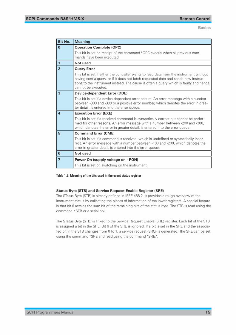
Bit No. Meaning
0 Operation Complete (OPC)
This bit is set on receipt of the command *OPC exactly when all previous com-mands have been executed.
1 Not used
2 Query Error
This bit is set if either the controller wants to read data from the instrument without having sent a query, or if it does not fetch requested data and sends new instruc-tions to the instrument instead. The cause is often a query which is faulty and hence cannot be executed.
3 Device-dependent Error (DDE)
This bit is set if a device-dependent error occurs. An error message with a number between -300 and -399 or a positive error number, which denotes the error in grea-ter detail, is entered into the error queue.
4 Execution Error (EXE)
This bit is set if a received command is syntactically correct but cannot be perfor-med for other reasons. An error message with a number between -200 and -300, which denotes the error in greater detail, is entered into the error queue.
5 Command Error (CME)
Thisbitissetifacommandisreceived,whichisundefinedorsyntacticallyincor-rect. An error message with a number between -100 and -200, which denotes the error in greater detail, is entered into the error queue.
6 Not used
7 Power On (supply voltage on - PON)
This bit is set on switching on the instrument.
Table 1.8: Meaning of the bits used in the event status register
Status Byte (STB) and Service Request Enable Register (SRE)TheSTatusByte(STB)isalreadydefinedinIEEE488.2.Itprovidesaroughoverviewoftheinstrument status by collecting the pieces of information of the lower registers. A special feature is that bit 6 acts as the sum bit of the remaining bits of the status byte. The STB is read using the command *STB or a serial poll.
The STatus Byte (STB) is linked to the Service Request Enable (SRE) register. Each bit of the STB is assigned a bit in the SRE. Bit 6 of the SRE is ignored. If a bit is set in the SRE and the associa-ted bit in the STB changes from 0 to 1, a service request (SRQ) is generated. The SRE can be set using the command *SRE and read using the command *SRE?.
SCPI Commands ¸HMS-X Remote Control
16
Basics
SCPI Programmers Manual
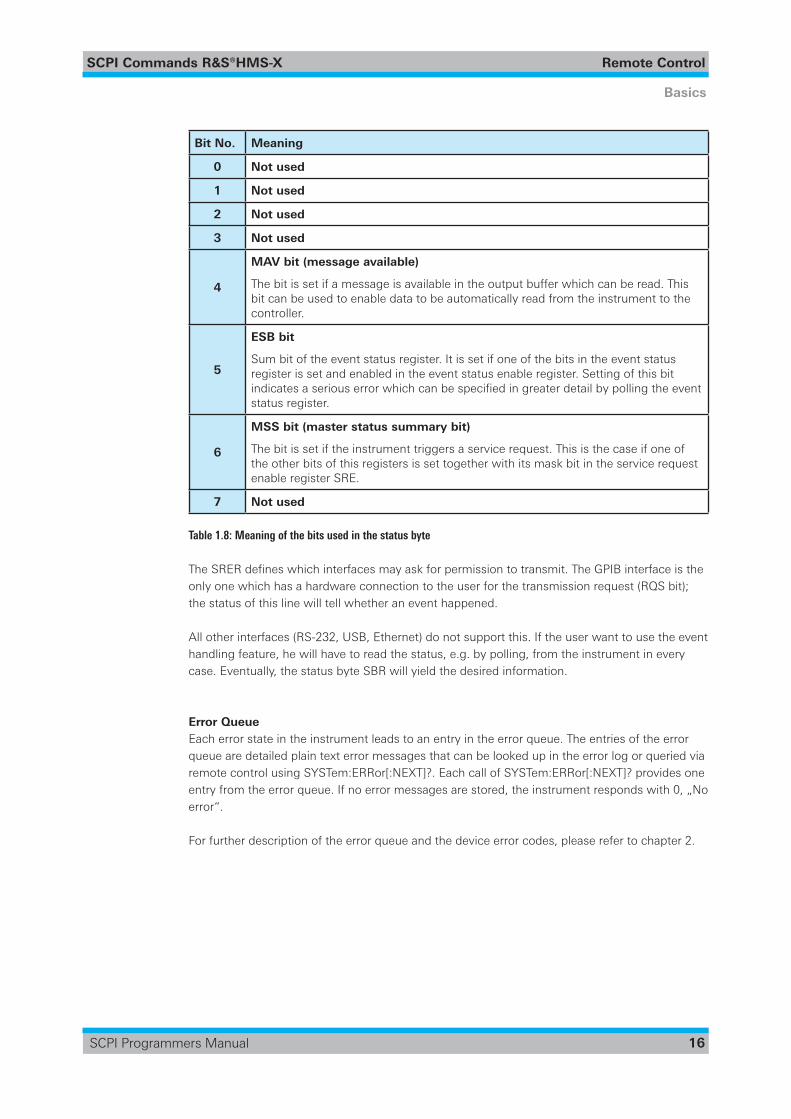
Bit No. Meaning
0 Not used
1 Not used
2 Not used
3 Not used
4
MAV bit (message available)
The bit is set if a message is available in the output buffer which can be read. This bit can be used to enable data to be automatically read from the instrument to the controller.
5
ESB bit
Sum bit of the event status register. It is set if one of the bits in the event status register is set and enabled in the event status enable register. Setting of this bit indicatesaseriouserrorwhichcanbespecifiedingreaterdetailbypollingtheeventstatus register.
6
MSS bit (master status summary bit)
The bit is set if the instrument triggers a service request. This is the case if one of the other bits of this registers is set together with its mask bit in the service request enable register SRE.
7 Not used
Table 1.8: Meaning of the bits used in the status byte
TheSRERdefineswhichinterfacesmayaskforpermissiontotransmit.TheGPIBinterfaceistheonly one which has a hardware connection to the user for the transmission request (RQS bit); the status of this line will tell whether an event happened.
All other interfaces (RS-232, USB, Ethernet) do not support this. If the user want to use the event handling feature, he will have to read the status, e.g. by polling, from the instrument in every case. Eventually, the status byte SBR will yield the desired information.
Error QueueEach error state in the instrument leads to an entry in the error queue. The entries of the error queue are detailed plain text error messages that can be looked up in the error log or queried via remote control using SYSTem:ERRor[:NEXT]?. Each call of SYSTem:ERRor[:NEXT]? provides one entry from the error queue. If no error messages are stored, the instrument responds with 0, „No error“.
For further description of the error queue and the device error codes, please refer to chapter 2.
SCPI Commands ¸HMS-X Remote Control
17
Command Reference
SCPI Programmers Manual
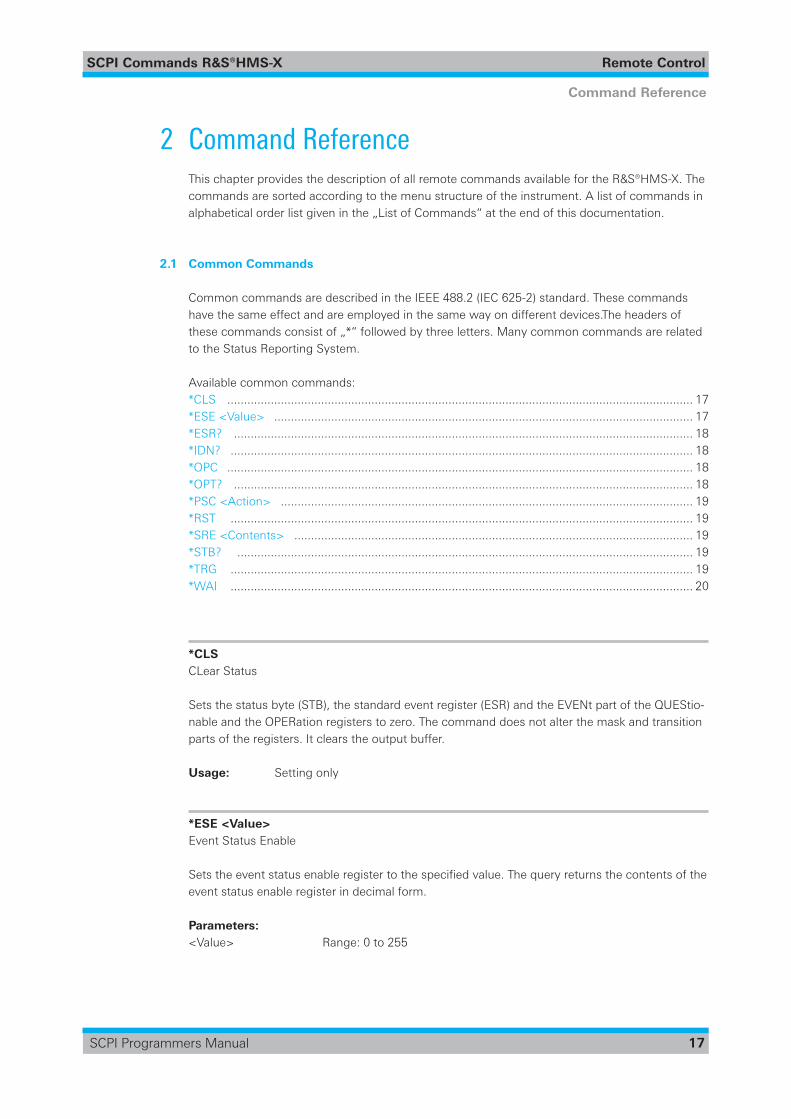
2 Command ReferenceThis chapter provides the description of all remote commands available for the ¸HMS-X. The commands are sorted according to the menu structure of the instrument. A list of commands in alphabetical order list given in the „List of Commands“ at the end of this documentation.
2.1 Common Commands
Common commands are described in the IEEE 488.2 (IEC 625-2) standard. These commands have the same effect and are employed in the same way on different devices.The headers of these commands consist of „*“ followed by three letters. Many common commands are related to the Status Reporting System.
Available common commands:*CLS ........................................................................................................................................... 17*ESE<Value> ............................................................................................................................. 17*ESR? ......................................................................................................................................... 18*IDN? .......................................................................................................................................... 18*OPC ........................................................................................................................................... 18*OPT? ......................................................................................................................................... 18*PSC<Action> ........................................................................................................................... 19*RST .......................................................................................................................................... 19*SRE<Contents> ....................................................................................................................... 19*STB? ........................................................................................................................................ 19*TRG .......................................................................................................................................... 19*WAI .......................................................................................................................................... 20
*CLS CLear Status
Sets the status byte (STB), the standard event register (ESR) and the EVENt part of the QUEStio-nable and the OPERation registers to zero. The command does not alter the mask and transition parts of the registers. It clears the output buffer.
Usage: Setting only
*ESE <Value> Event Status Enable
Setstheeventstatusenableregistertothespecifiedvalue.Thequeryreturnsthecontentsoftheevent status enable register in decimal form.
Parameters:<Value> Range:0to255

SCPI Commands ¸HMS-X Remote Control
18
Command Reference
SCPI Programmers Manual
*ESR? Event Status Read
Returns the contents of the event status register in decimal form and subsequently sets the register to zero.
Return values: <Contents> Range:0to255
Usage: Query only
*IDN? IDeNtification:returnstheinstrumentidentification.
Return values:<ID>,<devicetype>,<serialnumber>,<firmwareversion>
Example: Rohde&Schwarz,HMS-X,019442781,HW20011000,SW02.115
Usage: Query only
*OPC OPeration Complete
Sets bit 0 in the event status register when all preceding commands have been executed. This bit can be used to initiate a service request. The query form writes a „1“ into the output buffer as soon as all preceding commands have been executed. This is used for command synchronization.
*OPT? OPTionidentificationquery
Queries the options included in the instrument.
Return values: <Options> Thequeryreturnsalistofoptions.Theoptionsarereturnedatfixed
positions in a comma-separated string. A zero is returned for options that are not installed.
Usage: Query only
SCPI Commands ¸HMS-X Remote Control
19
Command Reference
SCPI Programmers Manual
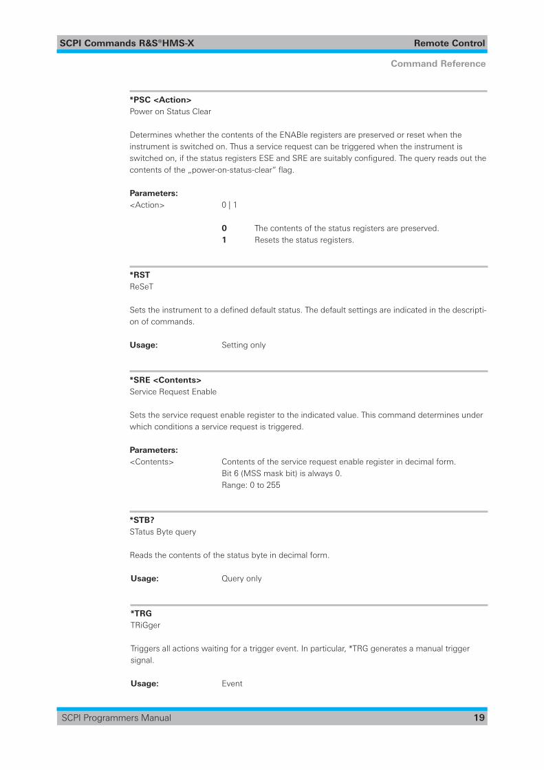
*PSC <Action> Power on Status Clear
Determines whether the contents of the ENABle registers are preserved or reset when the instrument is switched on. Thus a service request can be triggered when the instrument is switchedon,ifthestatusregistersESEandSREaresuitablyconfigured.Thequeryreadsoutthecontentsofthe„power-on-status-clear“flag.
Parameters: <Action> 0|1
0 The contents of the status registers are preserved. 1 Resets the status registers.
*RST ReSeT
Setstheinstrumenttoadefineddefaultstatus.Thedefaultsettingsareindicatedinthedescripti-on of commands.
Usage: Setting only
*SRE <Contents> Service Request Enable
Sets the service request enable register to the indicated value. This command determines under which conditions a service request is triggered.
Parameters: <Contents> Contentsoftheservicerequestenableregisterindecimalform. Bit 6 (MSS mask bit) is always 0. Range: 0 to 255
*STB? STatus Byte query
Reads the contents of the status byte in decimal form.
Usage: Query only
*TRG TRiGger
Triggers all actions waiting for a trigger event. In particular, *TRG generates a manual trigger signal.
Usage: Event
SCPI Commands ¸HMS-X Remote Control
20
Command Reference
SCPI Programmers Manual
*WAI WAIt to continue
Prevents servicing of the subsequent commands until all preceding commands have been exe-cuted and all signals have settled (see also command synchronization and *OPC).
Usage: Event
2.2 General Instrument Setup
SYSTem:LANGuage<Language> .............................................................................................. 20SYSTem:NAME .......................................................................................................................... 20SYSTem:DATE<Year>,<Month>,<Day> ................................................................................... 21SYSTem:TIME<Hour>,<Minute>,<Second> ............................................................................ 21SYSTem:SNUM? ....................................................................................................................... 21SYSTem:SOFTware? ................................................................................................................... 21SYSTem:HARDware? ................................................................................................................. 22SYSTem:TREE? ........................................................................................................................... 22SYSTem:ELISt? ........................................................................................................................... 22SYSTem:ERRor:[NEXT]?<Error> ............................................................................................... 22SYSTem:ERRor:ALL?<Error> .................................................................................................... 22SYST:PRESet .............................................................................................................................. 22SYSTem:AUTOtune .................................................................................................................... 23SYSTem:REFerence<Reference> .............................................................................................. 23
SYSTem:LANGuage <Language> Sets the language in which the softkey labels, help and other screen information can be displayed.Supportedlanguagesarelistedinthe„Specifications“datasheet.
Parameters: <Language> ENGLish|GERMan|FRENch|SPANish
*RST: Reset does not change the language
SYSTem:NAME Definesaninstrumentname.
Parameters: <Name> Stringwithmax.20characters
Example: SYST:NAME “MyHMS“

SCPI Commands ¸HMS-X Remote Control
21
Command Reference
SCPI Programmers Manual
SYSTem:DATE <Year>,<Month>,<Day> Specifiestheinternaldatefortheinstrument.
Parameters: <Year> Defaultunit:a
<Month> Range:1to12
<Day> Range:1to31 Default unit: d
Example: SYSTem:DATE 2014,10,1 Sets the device date to october 1st in the year 2014 SYSTem:DATE? Returns 2014,10,1
Usage: SCPIconfirmed
SYSTem:TIME <Hour>,<Minute>,<Second> Specifiestheinternaltimefortheinstrument.
Parameters: <Hour> Range:0to23 Default unit: h
<Minute> Range:0to59 Default unit: min
<Second> Range:0to59 Default unit: s
Example: SYSTem:TIME 12,15,0 Sets the time to quarter past twelve. SYSTem:TIME? Returns 12,15,0
Usage: SCPIconfirmed
SYSTem:SNUM? Queries the serial number of the instrument.
Usage: Query only
SYSTem:SOFTware? Queries the software revision oft he instrument.
Usage: Query only
SCPI Commands ¸HMS-X Remote Control
22
Command Reference
SCPI Programmers Manual
SYSTem:HARDware? Queries the hardware-ID of the instrument.
Usage: Query only
SYSTem:TREE? Queries a list of implemented remote commands.
Usage: Query only
SYSTem:ELISt? Queries the error list.
Usage: Query only
SYSTem:ERRor:[NEXT]? <Error> Queries the error/event queue for the oldest item and removes it from the queue. The response consists of an error number and a short description of the error. Positive error numbers are instrument-dependent. Negative error numbers are reserved by the SCPI standard.
Return values: <Error> Error/event_number,“Error/event_description>[;Devicedependentinfo]“ If the queue is empty, the response is 0,“No error“
Usage: Query only SCPIconfirmed
SYSTem:ERRor:ALL? <Error> Queries the error/event queue for all unread items and removes them from the queue. The response is a comma separated list of error number and a short description of the error in FIFO order. Positive error numbers are instrument-dependent. Negative error numbers are reserved by the SCPI standard.
Return values: <Error> Listof:Error/event_number,“Error/event_description>[;Devicedependentinfo]“ If the queue is empty, the response is 0,“No error”
Usage: Query only SCPIconfirmed
SYST:PRESet Resets the instrument to the default state, has the same effect as *RST.
Usage: Event

SCPI Commands ¸HMS-X Remote Control
23
Command Reference
SCPI Programmers Manual
SYSTem:AUTOtune Performs an autoset process: analyzes the signal and obtains appropriate sweep and trigger settings.
Usage: Event Asynchronous command
SYSTem:REFerence <Reference> Sets the system reference clock (10MHz) to internal or external source. The SYST:REF? query returns the current state of the system reference.
Parameters: <Reference> INTernal|EXTernal
INTernal Selects the internal 10MHz reference frequency.
EXTernal Selects the external reference frequency. The external 10MHz reference frequencysignalmustcomplywiththespecificationsgivenwith respect to frequency accuracy and amplitude (essential level = 10dBm)
*RST: INT
2.3 Trigger Commands TRIGger:SOURce<Source> ...................................................................................................... 23TRIGger:SLOPe<Slope> ............................................................................................................ 24TRIGger:SOFTware ..................................................................................................................... 24
TRIGger:SOURce <Source> Sets the trigger source. The TRIG:SOUR? query returns the current setting of the trigger source.
Parameters: <Source> IMMediate|EXTernal|VIDeo
IMMediate Selects the internal trigger source.
EXTernal Selects the external trigger source. The external trigger source has to be connected to the EXTERNAL TRIGGER connector on the front panel (TTL).
VIDeo Selects the video trigger. The video trigger can only be activated in zero span (span = 0 Hz).
*RST: IMM

SCPI Commands ¸HMS-X Remote Control
24
Command Reference
SCPI Programmers Manual
TRIGger:SLOPe <Slope> Sets the trigger slope. The TRIG:SLOP? query returns the current setting of the trigger slope.
Parameters: <Slope> POSitive|NEGative
POSitive Rising edge NEGative Falling edge
*RST: POS
TRIGger:SOFTware Executes a single trigger. The software trigger can only be used in single sweep mode.
Usage: Event
2.4 Configuration of the parameters
2.4.1 Bandwidth setting
BANDwidth:RBW<ValueinHz> ............................................................................................... 24BANDwidth:RBW? ..................................................................................................................... 25BANDwidth:RBW:AUTO {ON | OFF | 0 | 1} ................................................................................ 25BANDwidth:RBW:AUTO? ........................................................................................................... 25BANDwidth:VBW<ValueinHz> ............................................................................................... 25BANDwidth:VBW? ..................................................................................................................... 26BANDwidth:VBW:AUTO {ON | OFF | 0 | 1} ................................................................................ 26BANDwidth:VBW:AUTO? ........................................................................................................... 26
BANDwidth:RBW <Value in Hz> Setstheresolutionbandwidthfilter(RBW)inHz.Forremotecontroldecimalaswellasscientificnumberformat(e.g.1e6)isallowed.AllCISPRfilters(C200,C9k,C120k,C1M)areonlyavailablein receiver mode
Parameters:<ValueinHz> 100|300|1000|3000|10000|30000|100000|200000|300000| 1000000 | C200 | C9k | C120k | C1M
*RST: AUTO RBW
NOTICE The RBW filter 100Hz, 300Hz, 1kHz, 3kHz, CISPR 200Hz, CISPR 9kHz, CISPR 120kHz
and CISPR 1MHz are only available with installed HMS-EMC option / HV213 voucher. Scientific number format is not supported for the CISPR filters.

SCPI Commands ¸HMS-X Remote Control
25
Command Reference
SCPI Programmers Manual
BANDwidth:RBW? QueriestheRBWfiltervalueinHz.
Return values: CurrentRBWfiltervalueinHz.
Example: BAND:RBW 200000 BAND:RBW?, Response: 200000
BANDwidth:RBW:AUTO {ON | OFF | 0 | 1} ActivatesordeactivatestheautomaticRBWfiltersetting(AUTORBW).
Parameters: ON | 1: AutomaticRBWfiltersettingwillbeactivated. OFF | 0: AutomaticRBWfiltersettingwillbedeactivated
*RST: ON | 1
BANDwidth:RBW:AUTO? QueriestheAUTORBWfiltersettingstate.
Return values: ON | OFF
ON: AutomaticRBWfiltersettingisactivated. OFF: AutomaticRBWfiltersettingisdeactivated.
BANDwidth:VBW <Value in Hz> Setsthevideobandwidthfilter(VBW)inHz.Forremotecontroldecimalaswellasscientificnumberformat(e.g.1e6)isallowed.AllCISPRfilters(C200,C9k,C120k,C1M)areonlyavailablein receiver mode
Parameters:<ValueinHz> 10|30|100|300|1000|3000|10000|30000|1000000
*RST: AUTO VBW
NOTICE The VBW filter 10Hz, 30Hz, 100Hz and 300Hz are only available with installed HMS-
EMC option / HV213 voucher.

SCPI Commands ¸HMS-X Remote Control
26
Command Reference
SCPI Programmers Manual
BANDwidth:VBW? QueriestheVBWfiltervalueinHz.
Return values: CurrentVBWfiltervalueinHz.
Example: BAND:VBW 1000 BAND:VBW?, Response: 1000
BANDwidth:VBW:AUTO {ON | OFF | 0 | 1} ActivatesordeactivatestheautomaticVBWfiltersetting(AUTOVBW).
Parameters: ON | 1: AutomaticVBWfiltersettingwillbeactivated. OFF | 0: AutomaticVBWfiltersettingwillbedeactivated
*RST: ON | 1
BANDwidth:VBW:AUTO? QueriestheAUTOVBWfiltersettingstate.
Return values: ON | OFF
ON: AutomaticVBWfiltersettingisactivated. OFF: AutomaticVBWfiltersettingisdeactivated.
2.4.2 Amplitude setting
AMPLitude:ATTenuation<Setup> ............................................................................................. 27AMPLitude: ATTenuation? .......................................................................................................... 27AMPLitude:ATTenuation:LEVel? ................................................................................................. 27AMPLitude:RLEVel{<Value>|MINimum|MAXimum} ............................................................ 27AMPLitude:RLEVel? [MINimum | MAXimum] ............................................................................ 27AMPLitude:UNIT<Unit> ........................................................................................................... 28AMPLitude:UNIT? ...................................................................................................................... 28AMPLitude:RANGe<Range> .................................................................................................... 28AMPLitude:RANGe? ................................................................................................................... 29AMPLitude:TGATtenuation<Value> .......................................................................................... 29AMPLitude:TGATtenuation? ....................................................................................................... 29
SCPI Commands ¸HMS-X Remote Control
27
Command Reference
SCPI Programmers Manual
AMPLitude:ATTenuation <Setup> Selects the amplitude attenuation setting.
Parameters:<Setup> LNOIse|LDIStortion
LNOIse When adjusting reference level switching thresholds for attenuator and gain are optimised to get the best signal/noise ratio (LOW NOISE).
LDIStortion When adjusting reference level switching thresholds for attenuator and gain are optimised for lowest possible distortion (LOW DISTORTION).
*RST: LNOI
AMPLitude: ATTenuation? Queries the amplitude attenuation setting.
Return values: LNOI | LDIS
LNOI: The attenuation setting LOW NOISE is activated. LDIS: The attenuation setting LOW DISTORTION is activated.
AMPLitude:ATTenuation:LEVel? Queries the current setting of the attenuation level which is set automatically by the instrument. The RF attenuation setting at the input of the spectrum analyzer is directly coupled to the refe-rence level. If the reference level is high, RF attenuation is switched on in steps according to the table 6.1, so that the input mixer always remains in the linear range.
Usage: Query only
AMPLitude:RLEVel {<Value> | MINimum | MAXimum} Sets the reference level of the Y-axis in dBm, dBµV, V or W (see also: AMPL:UNIT). MIN selects the lowest reference level and MAX selects the highest reference level allowed.
Parameters:<Value> dBm|dBµV|V|W
*RST: 0.0E+00 (dBm)
AMPLitude:RLEVel? [MINimum | MAXimum] Queries the current (resp the minimum / maximum) reference level of the Y-axis.
Return values: e.g. AMPL:RLEV? MIN, Response: -1.100E+02

SCPI Commands ¸HMS-X Remote Control
28
Command Reference
SCPI Programmers Manual
AMPLitude:UNIT <Unit> Sets the unit of the amplitude reference level.
Parameters:<Unit> dBm|dBµV|V|W
*RST: DBM
AMPLitude:UNIT? Queries the current unit of the amplitude reference level.
Return values: dBm | dBµV | V | W
AMPLitude:RANGe <Range> Sets the range per division of the amplitude reference level and determines the resolution along the level axis in the measurement diagram.
Parameters:<Range> LINear|0.5|1|2|5|10
LINear: Linear percentage display (LIN%) 0.5: Amplitude reference level range of 0.5dB/DIV 1: Amplitude reference level range of 1dB/DIV 2: Amplitude reference level range of 2dB/DIV 5: Amplitude reference level range of 5dB/DIV 10: Amplitude reference level range of 10dB/DIV
*RST: 10.0 (= 10dB/DIV)
Table 6.1: Relation between reference level and automatic setting of RF attenuation
Preamplifier OFF Preamplifier ON
Reference Level ATT-Setup Low Noise
ATT-Setup Low Distortion
ATT-Setup Low Noise
ATT-Setup Low Distortion
Preamplifier
20 dBm 30 dB 30 dB 30 dB 30 dB OFF
15 dBm 30 dB 30 dB 30 dB 30 dB OFF
10 dBm 20 dB 30 dB 20 dB 30 dB OFF
5 dBm 20 dB 30 dB 20 dB 30 dB OFF
0 dBm 10 dB 20 dB 10 dB 20 dB OFF
–5 dBm 10 dB 20 dB 10 dB 20 dB OFF
–10 dBm 0 dB 10 dB 0 dB 10 dB OFF
–15 dBm 0 dB 10 dB 10 dB 10 dB ON
–20 dBm 0 dB 0 dB 10 dB 10 dB ON
≤–25dBm 0 dB 0 dB 0 dB 0 dB ON
SCPI Commands ¸HMS-X Remote Control
29
Command Reference
SCPI Programmers Manual
NOTICE The linear scaling is only available with activated reference level unit dBm resp. dBµV
and installed HMS-EMC option / HV213 voucher.
AMPLitude:RANGe? Queries the range per division of the amplitude reference level.
Return values: e.g. AMPL:RANG?, Response: 10.0 (= 10dB/DIV)
AMPLitude:TGATtenuation <Value> Sets the output of the tracking generator attenuation value (TG ATT).
Parameters:<Value> TGattenuationvaluein1dBsteps(20dBmax.).
NOTICE The tracking generator attenuation value can only be set with installed HMS-TG option
/ HV211 voucher.
AMPLitude:TGATtenuation? Queries the tracking generator attenuation value (TG ATT) in dB.
Return values: e.g. AMPL:TGAT?, Response: 0 (= 0dB)
2.4.3 Frequency setting
FREQuency:CENTer{<ValueinHz>|MARKer[n]|MINimum|MAXimum} ............................. 30FREQuency:CENTer? [MINimum | MAXimum] .......................................................................... 30FREQuency:CENTer:STEPsize{<Value>|SPAN01|SPAN05|STC|MINimum|MAXimum} . 30FREQuency:CENTer:STEPsize? [MINimum | MAXimum] ........................................................... 31FREQuency:SPAN{<ValueinHz>|LAST|FULL|ZERO|MINimum|MAXimum} ................. 31FREQuency:SPAN? [MINimum | MAXimum] ............................................................................. 31FREQuency:STARt{<ValueinHz>|MINimum|MAXimum} .................................................... 31FREQuency:STARt? [MINimum | MAXimum] ............................................................................ 32FREQuency:STOP{<ValueinHz>|MINimum|MAXimum} .................................................... 32FREQuency:STOP? [MINimum | MAXimum] ............................................................................. 32FREQuency:STEP{<ValueinHz>|MINimum|MAXimum} ..................................................... 32FREQuency:STEP? [MINimum | MAXimum] .............................................................................. 32

SCPI Commands ¸HMS-X Remote Control
30
Command Reference
SCPI Programmers Manual
FREQuency:CENTer {<Value in Hz> | MARKer[n] | MINimum | MAXimum} Sets the center frequency resp. sets the center frequency to the current marker frequency (MARK). MIN selects the lowest center frequency and MAX selects the highest center frequency.
Parameters:<ValueinHz> Dependingontheinstalledoption/voucherkey. 1.000500E+05 to 1.600000E+09
(1.000500E+05 to 3.000000E+09 with installed HMS-3G option / HV212 voucher)
*RST: 1.500000E+09 (with HMS-3G option / HV212 voucher)
FREQuency:CENTer? [MINimum | MAXimum] Queries the current (resp. minimum / maximum) center frequency value in Hz.
Return values: e.g. FREQ:CENT?, Response: 1.500000E+09
FREQuency:CENTer:STEPsize {<Value> | SPAN01 | SPAN05 | STC | MINimum | MAXi-mum} Sets the center frequency step size. MIN selects the lowest center frequency step size and MAX selects the highest center frequency step size.
Parameters:<Value> Dependingontheinstalledoption/voucherkey. 1.000E+02 to 1.000000E+09 (with HMS-3G option / HV212 voucher)
SPAN01 | SPAN05 | STC
SPAN01 The step size is always 1/10 of the currently selected span (= 1 vertical division).
SPAN05 The step size is always 1/2 of the currently selected span (= 5 vertical divisions).
STC (= Set To Center) The step size of the frequency is equal to the present center frequency. This mode is especially useful for the measurement of harmonics because each step will move the center frequency to the next harmonic
*RST: SPAN01

SCPI Commands ¸HMS-X Remote Control
31
Command Reference
SCPI Programmers Manual
FREQuency:CENTer:STEPsize? [MINimum | MAXimum] Queries the current (resp. minimum / maximum) center frequency step size value in Hz.
Return values: e.g. FREQ:CENT:STEP?, Response: 2.999900E+08
FREQuency:SPAN {<Value in Hz> | LAST | FULL | ZERO | MINimum | MAXimum} Sets the frequency span. MIN selects the lowest frequency span and MAX selects the highest frequency span.
Parameters:<ValueinHz> Dependingontheinstalledoption/voucherkey. 1.000E+02 to 2.999900E+09 (with HMS-3G option / HV212 voucher)
LAST | FULL | ZERO
LAST Restores the last span setting.
FULL Full span from 1MHz resp. 100Hz (with HMS-EMC option / HV213 voucher) to 1.6 GHz resp. 3 GHz (with HMS-3G option / HV212 voucher).
ZERO In zero span mode (0 Hz) the spectrum analyzer acts similar to a receiver tuned to the center frequency. In this case the trace display does not represent a spectrum, but the amplitude over time. In other words the spectrum analyzer acts like a selective oscilloscope.
*RST: 2.999900E+09 (with HMS-3G option / HV212 voucher)
FREQuency:SPAN? [MINimum | MAXimum] Queries the current (resp. minimum / maximum) frequency span value in Hz.
Return values: e.g. FREQ:SPAN?, Response: 2.800000E+09
FREQuency:STARt {<Value in Hz> | MINimum | MAXimum} Sets the start frequency in Hz. MIN selects the lowest start frequency and MAX selects the high-est start frequency.
Parameters:<ValueinHz> Dependingontheinstalledoption/voucherkey. 1.000000E+05 to 3.000000E+09 (with HMS-3G option / HV212 voucher)
*RST: 1.000000E+05 (with HMS-3G option / HV212 voucher)
SCPI Commands ¸HMS-X Remote Control
32
Command Reference
SCPI Programmers Manual
FREQuency:STARt? [MINimum | MAXimum] Queries the current (resp. minimum / maximum) start frequency value in Hz.
Return values: e.g. FREQ:STAR?, Response: 1.000000E+05
FREQuency:STOP { <Value in Hz> | MINimum | MAXimum} Sets the stop frequency in Hz. MIN selects the lowest stop frequency and MAX selects the high-est stop frequency.
Parameters:<ValueinHz> Dependingontheinstalledoption/voucherkey. 1.001000E+05 to 3.000000E+09 (with HMS-3G option / HV212 voucher)
*RST: 3.000000E+09 (with HMS-3G option / HV212 voucher)
FREQuency:STOP? [MINimum | MAXimum] Queries the current (resp. minimum / maximum) stop frequency value in Hz.
Return values: e.g. FREQ:STOP?, Response: 3.000000E+09
FREQuency:STEP {<Value in Hz> | MINimum | MAXimum} Sets the center frequency step size. MIN selects the lowest center frequency step size and MAX selects the highest center frequency step size.
Parameters:<Value> Dependingontheinstalledoption/voucherkey. 1.000E+02 to 1.000000E+09 (with HMS-3G option / HV212 voucher)
FREQuency:STEP? [MINimum | MAXimum] Queries the current (resp. minimum / maximum) center frequency step size value in Hz.
Return values: e.g. FREQ:CENT:STEP?, Response: 2.999900E+08

SCPI Commands ¸HMS-X Remote Control
33
Command Reference
SCPI Programmers Manual
2.4.4 Sweep setting
SWEep:TIME{<Valueins>} ...................................................................................................... 33SWEep:TIME? ............................................................................................................................ 33SWEep:TIME:AUTO {ON | OFF | 0 | 1} ....................................................................................... 33SWEep:TIME:AUTO? .................................................................................................................. 33SWEep:MODE<Mode> ............................................................................................................ 34SWEep:MODE? .......................................................................................................................... 34SWEep:STATe?<State> ............................................................................................................. 34
SWEep:TIME {<Value in s>} Sets the time in s required to sweep from the start frequency to the stop frequency.
Paramaters:<Valueins> 2.000E-02to1.000E+02
*RST: 1.000E-01
SWEep:TIME? Queries the current sweep time value in s.
Return values: e.g. SWE:TIME?, Response: 1.000E-01
SWEep:TIME:AUTO {ON | OFF | 0 | 1} Activates or deactivates the automatic sweep time setting (AUTO).
Parameters: ON | 1: Automatic sweep time setting will be activated. OFF | 0: Automatic sweep time setting will be deactivated.
*RST: ON | 1
SWEep:TIME:AUTO? Queries the AUTO sweep time setting state.
Return values: ON | OFF
ON: Automatic sweep time setting is activated. OFF: Automatic sweep time setting is deactivated.

SCPI Commands ¸HMS-X Remote Control
34
Command Reference
SCPI Programmers Manual
SWEep:MODE <Mode> Sets the sweep time mode.
Parameters:<Mode> CONTinous|SINGle
CONTinous The spectrum analyzer will sweep the selected frequency range continuously. After a sweep was completed, a new one will be started and the display refreshed.
SINGle The spectrum analyzer will sweep the frequency range once or it displays the video signal vs. time if the span is set to zero. The instrument will only repeat the measurement after sending the SING command again.
*RST: CONT
SWEep:MODE? Queries the current sweep mode setting.
Return values: CONT | SING
CONT: Continous sweep mode SING: Single sweep mode.
SWEep:STATe? <State> Queries the current sweep state in SINGle sweep mode.
Return values:<State> RUN|READY
RUN: The single sweep is running. READY: The single sweep is completed and the instrument is ready for a new single sweep.
Usage: Query only

SCPI Commands ¸HMS-X Remote Control
35
Command Reference
SCPI Programmers Manual
2.4.5 Measurement commands
MEASure:TGENerator {ON | OFF | 0 | 1} .................................................................................... 35MEASure:TGENerator? .............................................................................................................. 35MEAS:PAMP {ON | OFF | 0 | 1} .................................................................................................. 35MEAS:PAMP? ............................................................................................................................ 36MEASure {CFRX | M1RX} .......................................................................................................... 36MEASure:UNCAl? ...................................................................................................................... 36
MEASure:TGENerator {ON | OFF | 0 | 1} Activates or deactivates the tracking generator function.
Parameters: ON | 1: Tracking generator function will be activated. OFF | 0: Tracking generator function will be deactivated
*RST: OFF | 0
NOTICE The tracking generator function can only be activated with installed HMS-TG option /
HV211 voucher.
MEASure:TGENerator? Queries the tracking generator function state.
Return values: ON | OFF
ON: Tracking generator function is activated. OFF: Tracking generator function is deactivated.
MEAS:PAMP {ON | OFF | 0 | 1} Activatesordeactivatesthepreamplifierfunction.
Parameters: ON | 1: Preamplifierfunctionwillbeactivated. OFF | 0: Preamplifierfunctionwillbedeactivated.
*RST: OFF | 0
NOTICE The preamplifier function can only be activated with installed HMS-EMC option /
HV213 voucher.

SCPI Commands ¸HMS-X Remote Control
36
Command Reference
SCPI Programmers Manual
MEAS:PAMP? Queriesthepreamplifierfunctionstate.
Return values: ON | OFF
ON: Preamplifierfunctionisactivated. OFF: Preamplifierfunctionisdeactivated.
MEASure {CFRX | M1RX} Activates the receiver mode with the actual center frequency (CFRX) or marker M1 setting (M1RX).
Parameters: CFRX: Activates the receiver mode tuned to the actual center frequency. M1RX: Activates the receiver mode tuned to the actual frequency of marker M1.
MEASure:UNCAl? Queries whether the current instrument setting displays the “UNCAL” message or not.
Return values: FALSE | TRUE
FALSE: The UNCAL message is not displayed. TRUE: The UNCAL message is displayed.
Usage: Query only

SCPI Commands ¸HMS-X Remote Control
37
Command Reference
SCPI Programmers Manual
2.4.6 Marker Settings
MARKer[n]:STATe {OFF | ON | 0 | 1} ........................................................................................... 37MARKer[n]:STATe? ..................................................................................................................... 37MARKer[n]:MODE {POSition | DELTa} ....................................................................................... 38MARKer[n]:MODE? .................................................................................................................... 38MARKer:FCOunter:STATe {OFF | ON | 0 | 1} ............................................................................... 38MARKer:FCOunter:STATe? ......................................................................................................... 38MARKer:FCOunter:VALue? ........................................................................................................ 38MARKer:AOFF ............................................................................................................................ 39MARKer[n]:[SET]:FREQuency{<ValueinHz>|MINimum|MAXimum} ................................... 39MARKer[n]:[SET]:FREQuency? ................................................................................................... 39MARKer[n][:SET]:CENTer ........................................................................................................... 39MARKer[n]:NOISe {OFF | ON | 0 | 1} .......................................................................................... 39MARKer[n]:NOISe? ..................................................................................................................... 40MARKer[n][:SET]:LEVel? ............................................................................................................. 40MARKer[n][:SET]:REFerence ...................................................................................................... 40
MARKer[n]:STATe {OFF | ON | 0 | 1} Activates or deactivates the selected marker. Up to 8 different markers (M1 to M8) can be se-lected.
Parameters: <n> 1...8
<State> ON | 1: Selected marker will be activated. OFF | 0: Selected marker will be deactivated
*RST: OFF | 0
MARKer[n]:STATe? Queries the state of the selected marker M1 to M8.
Parameters: <n> 1...8
Return values: ON | OFF
ON: Selected marker is activated. OFF: Selected marker is deactivated.
Example: MARK2:STAT ON MARK2:STAT?, Response: ON

SCPI Commands ¸HMS-X Remote Control
38
Command Reference
SCPI Programmers Manual
MARKer[n]:MODE {POSition | DELTa} Switches the selected marker to absolute position (M) or to delta marker mode (D). If two different markers are activated, you can calculate the delta between the two markers with the delta mode. The delta marker level is always relative to the level of the main marker (Marker1). If a marker is set to delta mode it is marked by a “D” to distinguish it from a standard marker designated by a leading “M”.
Parameters: <n> 1...8
<Mode> POSition|DELTa
POSition: Absolute marker position (M). DELTa: Delta marker mode (D).
MARKer[n]:MODE? Queries the current marker mode.
Parameters: <n> 1...8
Return values: POS | DELT
MARKer:FCOunter:STATe {OFF | ON | 0 | 1} Activates or deactivates the frequency counter functionality for marker M1. The values for the frequency marker will be calculated by hardware (TCXO).
Parameters: ON | 1: Frequency counter function for M1 will be activated. OFF | 0: Frequency counter function for M1 will be deactivated
*RST: OFF | 0
MARKer:FCOunter:STATe? Queries the state of the frequency counter functionality.
Return values: ON | OFF
ON: Frequency counter function for M1 is activated. OFF: Frequency counter function for M1 is deactivated.
MARKer:FCOunter:VALue? Queries the current value of the frequency counter.
Return values: Numeric value in Hz.
e.g. 2.925134E+09
Usage: Query only

SCPI Commands ¸HMS-X Remote Control
39
Command Reference
SCPI Programmers Manual
MARKer:AOFF Deactivates all activated markers.
Usage: Event
MARKer[n]:[SET]:FREQuency {<Value in Hz> | MINimum | MAXimum} Sets the frequency position of the selected marker.
Parameters:<n> 1...8
<ValueinHz> Dependingontheinstalledoption/voucherkey. 1.000500E+05 to 1.600000E+09
(1.000500E+05 to 3.000000E+09 with installed HMS-3G option / HV212 voucher)
MIN: 1.0000E+05 MAX: 1.600000E+09 resp. 3.000000E+09
MARKer[n]:[SET]:FREQuency? Queries the frequency position of the selected marker.
Parameters:<n> 1...8
Return values: Numeric value in Hz.
MARKer[n][:SET]:CENTer Sets the selected marker to center frequency.
Parameters:<n> 1...8
Usage: Event
MARKer[n]:NOISe {OFF | ON | 0 | 1} Activates or deactivates the noise marker functionality for the selected marker. The noise func-tion is used to calculate the noise power density at the marker position.
Parameters:<n> 1...8
<State> ON | 1: Noise marker function will be activated. OFF | 0: Noise marker function will be deactivated
*RST: OFF | 0

SCPI Commands ¸HMS-X Remote Control
40
Command Reference
SCPI Programmers Manual
MARKer[n]:NOISe? Queries the noise marker functionality state of the selected marker.
Parameters:<n> 1...8
Return values: ON | OFF
ON: Noise marker function is activated. OFF: Noise marker function is deactivated.
MARKer[n][:SET]:LEVel? Queries the level of the selected marker.
Parameters:<n> 1...8
Return values: Numeric value depending on the amplitude unit setting (dBm/dBµV).
MARKer[n][:SET]:REFerence Sets the reference level to the current marker value of the selected marker.
Parameters:<n> 1...8
Usage: Event
2.4.7 Peak Search commands
MARKer[n]:MAXimum:PEAK ...................................................................................................... 40MARKer[n]:MAXimum:NEXTpeak .............................................................................................. 41MARKer[n]:MAXimum:LEFT ...................................................................................................... 41MARKer[n]:MAXimum:RIGHt ..................................................................................................... 41MARKer[n]:MINimum ................................................................................................................ 41MARKer[n]:MAXimum:ALL ........................................................................................................ 41
MARKer[n]:MAXimum:PEAK Sets the selected marker to the highest peak of the actual measurement result.
Parameters:<n> 1...8
Usage: Event

SCPI Commands ¸HMS-X Remote Control
41
Command Reference
SCPI Programmers Manual
MARKer[n]:MAXimum:NEXTpeak Sets the selected marker to the next highest peak of the actual measurement result.
Parameters:<n> 1...8
Usage: Event
MARKer[n]:MAXimum:LEFT Sets the selected marker to the next left peak of the actual measurement result.
Parameters:<n> 1...8
Usage: Event
MARKer[n]:MAXimum:RIGHt Sets the selected marker to the next right peak of the actual measurement result.
Parameters:<n> 1...8
Usage: Event
MARKer[n]:MINimum Sets the selected marker to the minimum peak of the actual measurement result.
Parameters:<n> 1...8
Usage: Event
MARKer[n]:MAXimum:ALL Sets all activated markers to the highest peak.
Parameters:<n> 1...8
Usage: Event
SCPI Commands ¸HMS-X Remote Control
42
Command Reference
SCPI Programmers Manual
2.5 Basic Display Settings
DISPlay:TRACe {OFF | ON | 0 | 1} ............................................................................................... 42DISPlay:TRACe? ......................................................................................................................... 42DISPlay:TRACe:INTensity{<Valueinpercent>|MINimum|MAXimum} ................................. 42DISPlay:TRACe:INTensity? ......................................................................................................... 43DISPlay:BACKlight{<Valueinpercent>|MINimum|MAXimum} ............................................ 43DISPlay:BACKlight? .................................................................................................................... 43DISPlay:GRID{<Valueinpercent>|MINimum|MAXimum} .................................................... 43DISPlay:GRID? ............................................................................................................................ 43DISPlay:GRID:SETup {RETicle | LINE | OFF} ............................................................................... 43DISPlay:GRID:SETup? ................................................................................................................. 44DISPlay:GRID:SCALe {OFF | ON | 0 | 1} ..................................................................................... 44DISPlay:GRID:SCALe? ................................................................................................................ 44DISPlay:TRANsparancy{<Valueinpercent>|MINimum|MAXimum} .................................... 44DISPlay:TRANsparancy? [MINimum | MAXimum] ..................................................................... 44LED:BRIGhtness {HIGH | LOW} ................................................................................................. 44LED:BRIGhtness? ....................................................................................................................... 45
DISPlay:TRACe {OFF | ON | 0 | 1} Activates or deactivates the trace display.
Parameters: ON | 1: Trace display will be activated. OFF | 0: Trace display will be deactivated
*RST: ON | 1
DISPlay:TRACe? Queries the state of the trace display.
Return values: ON | OFF
ON: Trace display is activated. OFF: Trace display is deactivated.
DISPlay:TRACe:INTensity {<Value in percent> | MINimum | MAXimum} Definesthetraceintensityinthediagram.*RSTdoesnotchangetheintensity.
Parameters: <Valueinpercent> Range:0to100
MIN: 0 MAX: 100
SCPI Commands ¸HMS-X Remote Control
43
Command Reference
SCPI Programmers Manual
DISPlay:TRACe:INTensity? Queries the current setting of the trace intensity.
Return values: 0...100 (value in %)
DISPlay:BACKlight {<Value in percent> | MINimum | MAXimum} Definestheintensityofthebackgroundlightingofthedisplay.*RSTdoesnotchangetheintensity.
Parameters: <Valueinpercent> Range:10to100
MIN: 10 MAX: 100
DISPlay:BACKlight? Queries the current setting of the trace backlight intensity.
Return values: 10...100 (value in %)
DISPlay:GRID {<Value in percent> | MINimum | MAXimum} Definesthedisplayintensityofthegrid.*RSTdoesnotchangetheintensity.
Parameters: <Valueinpercent> Range:0to100
MIN: 0 MAX: 100
DISPlay:GRID? Queries the current setting of the grid intensity.
Return values: 0...100 (value in %)
DISPlay:GRID:SETup {RETicle | LINE | OFF} Definesthegriddisplay.
Parameters: <Setup> LINE|RETicle|OFF
LINE: Displays the grid as horizontal and vertical lines. RETicle: Displays crosshairs instead of a grid. OFF: No grid.
*RST: LINE

SCPI Commands ¸HMS-X Remote Control
44
Command Reference
SCPI Programmers Manual
DISPlay:GRID:SETup? Queries the grid display setup.
Return values: LINE | RET | OFF
DISPlay:GRID:SCALe {OFF | ON | 0 | 1} Activates or deactivates the grid scale display.
Parameters: ON | 1: Grid scale will be activated. OFF | 0: Grid scale will be deactivated
*RST: ON | 1
DISPlay:GRID:SCALe? Queries the state of the grid scale display.
Return values: ON | OFF
ON: Grid scale is activated. OFF: Grid scale is deactivated.
DISPlay:TRANsparancy {<Value in percent> | MINimum | MAXimum} Definesthedisplaytransparancy.
Parameters: <Valueinpercent> Range:0to100
MIN: 0 MAX: 100
DISPlay:TRANsparancy? [MINimum | MAXimum] Queries the current setting of the display transparancy.
Return values: 0...100 (value in %)
LED:BRIGhtness {HIGH | LOW} DefinestheLEDbrightnessoftheinstrumentfrontsidebuttons.
Parameters: <Brightness> HIGH|LOW
HIGH: High LED brightness. LOW: Low LED brightness.
SCPI Commands ¸HMS-X Remote Control
45
Command Reference
SCPI Programmers Manual
LED:BRIGhtness? Queries the current setting of the LED brightness.
Return values: HIGH | LOW
2.6 Trace settings
TRACe:MODE {CLR | MAXimum | MINimum | AVERage | HOLD} ............................................ 45TRACe:MODE? ........................................................................................................................... 46TRACe:MEMory:SAVE ............................................................................................................... 46TRACE:MEMory:SHOW {ON | OFF | 0 | 1} ................................................................................. 46TRACE:MEMory:SHOW? ........................................................................................................... 46TRACe:DETector {AUTO | SAMPle | MAXimum | MINimum} .................................................... 46TRACe:DETector? ....................................................................................................................... 47TRACe:MATH {OFF | TMEM | MTRace} ..................................................................................... 47TRACe:MATH? ........................................................................................................................... 47TRACe:DATA? ............................................................................................................................. 47TRACe:DATA:FORMat {BIN | CSV} ............................................................................................. 47TRACe:DATA:FORMat? .............................................................................................................. 48TRACe:DATA:BORDer {LSBFirst | MSBFirst} .............................................................................. 48TRACe:DATA:BORDer? ............................................................................................................... 48
TRACe:MODE {CLR | MAXimum | MINimum | AVERage | HOLD} Definesthetracemode.
Parameters:<Mode> CLR|MAXimum|MINimum|AVErage|HOLD
CLR: Clear / Write; clears the old trace during a new sweep. MAXimum: Max Hold; the trace indicates the maximum value that has been measured up to that point in time. MINimum: Min Hold; the trace indicates the minimum value that has been measured up to that point in time. AVERage: The R&S®HMS-X takes the level average over consecutive traces. HOLD: Freezes the presently displayed trace; the measure- ment is aborted; allows subsequent evaluation of spectra with the aid of the marker.
*RST: CLR
SCPI Commands ¸HMS-X Remote Control
46
Command Reference
SCPI Programmers Manual
TRACe:MODE? Queries the current trace mode setting.
Return values: CLR | MAX | MIN | AVER | HOLD
TRACe:MEMory:SAVE Stores a trace into background curve memory.
Usage: Event
TRACE:MEMory:SHOW {ON | OFF | 0 | 1} Shows a previous stored reference trace. The stored trace in white can be compared with the presently displayed trace.
Parameters: ON | 1: The previous stored reference trace will be displayed. OFF | 0: The previous stored reference trace is turned off.
TRACE:MEMory:SHOW? Queries the state of the previous stored trace.
Return values: ON | OFF
ON: The previous stored reference trace is displayed. OFF: The previous stored reference trace is not displayed.
TRACe:DETector {AUTO | SAMPle | MAXimum | MINimum} Definesthetracedetector.
Parameters:<Detector> AUTO|SAMPle|MAXimum|MINimum
AUTO: Displays the maximum and minimum level at each pixel for the frequency range represented by that pixel, no signals will be lost. SAMPle: Only displays an arbitrary point within a display pixel. The sample detector should always be used for measurements with span = 0Hz, as this is the only way of correctly representing the timing of the video signal. MAXimum: In contrast to the auto peak detector this detector onlyfindsthemaximumvaluewithinthefrequency range associated with one trace pixel. MINimum: Yields the minimum value of the spectrum within a pixel of the trace. Sine signals are displayed with correct level, but noise-like signals are suppressed.
*RST: AUTO
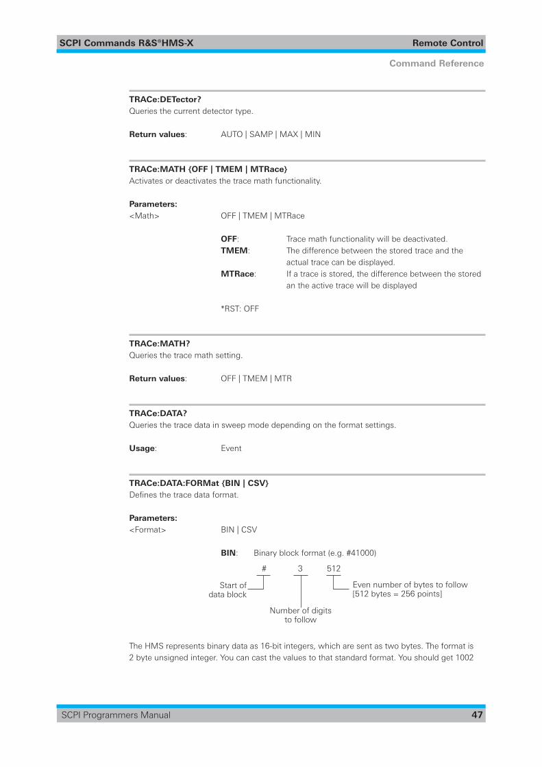
SCPI Commands ¸HMS-X Remote Control
47
Command Reference
SCPI Programmers Manual
TRACe:DETector? Queries the current detector type.
Return values: AUTO | SAMP | MAX | MIN
TRACe:MATH {OFF | TMEM | MTRace} Activates or deactivates the trace math functionality.
Parameters:<Math> OFF|TMEM|MTRace
OFF: Trace math functionality will be deactivated. TMEM: The difference between the stored trace and the actual trace can be displayed. MTRace: If a trace is stored, the difference between the stored an the active trace will be displayed
*RST: OFF
TRACe:MATH? Queries the trace math setting.
Return values: OFF | TMEM | MTR
TRACe:DATA? Queries the trace data in sweep mode depending on the format settings.
Usage: Event
TRACe:DATA:FORMat {BIN | CSV} Definesthetracedataformat.
Parameters:<Format> BIN|CSV
BIN: Binary block format (e.g. #41000)
The HMS represents binary data as 16-bit integers, which are sent as two bytes. The format is 2 byte unsigned integer. You can cast the values to that standard format. You should get 1002
# 3 512
Start ofdata block
Number of digitsto follow
Even number of bytes to follow[512 bytes = 256 points]

SCPI Commands ¸HMS-X Remote Control
48
Command Reference
SCPI Programmers Manual
points because you receive in standard mode MIN and MAX values for each frequency. If you are using MIN PEAK or MAX PEAK detector you wil receive 501 points.
In binary block format, the values transmitted are the converter values (direct raw data).
NOTICE The number of data points with binary block format is fixed (501 data points) and can
not be canged.
CSV: Comma-separated list of values [Hz],Trace1[dBm] [Hz],Trace1[dBm] 1.000000000E+05,-8.77032E+01 1.000000000E+05,5.91248E+00
TRACe:DATA:FORMat? Queries the trace data format.
Return values: BIN | CSV
TRACe:DATA:BORDer {LSBFirst | MSBFirst} Definesthebyteorderofthetracedata.
Parameters:<Border> LSBFirst|MSBFirst
LSBFirst: TransmitstheLeast-Significant-Bitatfirst. MSBFirst: TransmitstheMost-Significant-Bitatfirst.
TRACe:DATA:BORDer? Queries the data border type.
Return values: LSBF | MSBF
SCPI Commands ¸HMS-X Remote Control
49
Command Reference
SCPI Programmers Manual
2.7 Output Control
HCOPy:DATA? ............................................................................................................................ 49HCOPy:FORMat ......................................................................................................................... 49HCOPy:SIZE:X? .......................................................................................................................... 49HCOPy:SIZE:Y? .......................................................................................................................... 49
HCOPy:DATA? Returns the actual display content (screenshot) in block format.
Example: - Reading the screenshot data bytes -Removingthespecificheaderandsavingthedatastream
#6333878BM6 #6 = 6 letters following 333878 = number of bytes to be transmitted BM=BMPfileformat
In order to get a valid BMP which can be opened by any standard image viewer, the header information must be stripped down and removeduntilthefilestartswith„BM6“.
Usage: Query only
HCOPy:FORMat Definesthedataformatofthescreenshot.
Parameters:<Format> BMP: Windows Bitmap Format
HCOPy:SIZE:X? Queries the horizontal expansion of the screenshots.
Usage: Query only
HCOPy:SIZE:Y? Queries the vertical expansion of the screenshots.
Usage: Query only
SCPI Commands ¸HMS-X Remote Control
50
Command Reference
SCPI Programmers Manual
3 SCPI Commands in alphabetic order
AMPLitude: ATTenuation? .......................................................................................................... 27AMPLitude:ATTenuation:LEVel? ................................................................................................. 27AMPLitude:ATTenuation<Setup> ............................................................................................. 27AMPLitude:RANGe? ................................................................................................................... 29AMPLitude:RANGe<Range> .................................................................................................... 28AMPLitude:RLEVel? [MINimum | MAXimum] ............................................................................ 27AMPLitude:RLEVel{<Value>|MINimum|MAXimum} ............................................................ 27AMPLitude:TGATtenuation? ....................................................................................................... 29AMPLitude:TGATtenuation<Value> .......................................................................................... 29AMPLitude:UNIT? ...................................................................................................................... 28AMPLitude:UNIT<Unit> ........................................................................................................... 28
BANDwidth:RBW? ..................................................................................................................... 25BANDwidth:RBW:AUTO? ........................................................................................................... 25BANDwidth:RBW:AUTO {ON | OFF | 0 | 1} ................................................................................ 25BANDwidth:RBW<ValueinHz> ............................................................................................... 24BANDwidth:VBW? ..................................................................................................................... 26BANDwidth:VBW:AUTO? ........................................................................................................... 26BANDwidth:VBW:AUTO {ON | OFF | 0 | 1} ................................................................................ 26BANDwidth:VBW<ValueinHz> ............................................................................................... 25
*CLS ........................................................................................................................................... 17
DISPlay:BACKlight? .................................................................................................................... 43DISPlay:BACKlight{<Valueinpercent>|MINimum|MAXimum} ............................................ 43DISPlay:GRID? ............................................................................................................................ 43DISPlay:GRID:SCALe? ................................................................................................................ 44DISPlay:GRID:SCALe {OFF | ON | 0 | 1} ..................................................................................... 44DISPlay:GRID:SETup? ................................................................................................................. 44DISPlay:GRID:SETup {RETicle | LINE | OFF} ............................................................................... 43DISPlay:GRID{<Valueinpercent>|MINimum|MAXimum} .................................................... 43DISPlay:TRACe? ......................................................................................................................... 42DISPlay:TRACe:INTensity? ......................................................................................................... 43DISPlay:TRACe:INTensity{<Valueinpercent>|MINimum|MAXimum} ................................. 42DISPlay:TRACe {OFF | ON | 0 | 1} ............................................................................................... 42DISPlay:TRANsparancy? [MINimum | MAXimum] ..................................................................... 44DISPlay:TRANsparancy{<Valueinpercent>|MINimum|MAXimum} .................................... 44
*ESE<Value> ............................................................................................................................. 17*ESR? ......................................................................................................................................... 18
FREQuency:CENTer? [MINimum | MAXimum] .......................................................................... 30FREQuency:CENTer:STEPsize? [MINimum | MAXimum] ........................................................... 31FREQuency:CENTer:STEPsize{<Value>|SPAN01|SPAN05|STC|MINimum|MAXimum} . 30FREQuency:CENTer{<ValueinHz>|MARKer[n]|MINimum|MAXimum} ............................. 30FREQuency:SPAN? [MINimum | MAXimum] ............................................................................. 31FREQuency:SPAN{<ValueinHz>|LAST|FULL|ZERO|MINimum|MAXimum} ................. 31

SCPI Commands ¸HMS-X Remote Control
51
Command Reference
SCPI Programmers Manual
FREQuency:STARt? [MINimum | MAXimum] ............................................................................ 32FREQuency:STARt{<ValueinHz>|MINimum|MAXimum} .................................................... 31FREQuency:STEP? [MINimum | MAXimum] .............................................................................. 32FREQuency:STEP{<ValueinHz>|MINimum|MAXimum} ..................................................... 32FREQuency:STOP? [MINimum | MAXimum] ............................................................................. 32FREQuency:STOP{<ValueinHz>|MINimum|MAXimum} .................................................... 32
HCOPy:DATA? ............................................................................................................................ 49HCOPy:FORMat ......................................................................................................................... 49HCOPy:SIZE:X? .......................................................................................................................... 49HCOPy:SIZE:Y? .......................................................................................................................... 49
*IDN? .......................................................................................................................................... 18
LED:BRIGhtness? ....................................................................................................................... 45LED:BRIGhtness {HIGH | LOW} ................................................................................................. 44
MARKer:AOFF ............................................................................................................................ 39MARKer:FCOunter:STATe? ......................................................................................................... 38MARKer:FCOunter:STATe {OFF | ON | 0 | 1} ............................................................................... 38MARKer:FCOunter:VALue? ........................................................................................................ 38MARKer[n]:MAXimum:ALL ........................................................................................................ 41MARKer[n]:MAXimum:LEFT ...................................................................................................... 41MARKer[n]:MAXimum:NEXTpeak .............................................................................................. 41MARKer[n]:MAXimum:PEAK ...................................................................................................... 40MARKer[n]:MAXimum:RIGHt ..................................................................................................... 41MARKer[n]:MINimum ................................................................................................................ 41MARKer[n]:MODE? .................................................................................................................... 38MARKer[n]:MODE {POSition | DELTa} ....................................................................................... 38MARKer[n]:NOISe? ..................................................................................................................... 40MARKer[n]:NOISe {OFF | ON | 0 | 1} .......................................................................................... 39MARKer[n][:SET]:CENTer ........................................................................................................... 39MARKer[n]:[SET]:FREQuency? ................................................................................................... 39MARKer[n]:[SET]:FREQuency{<ValueinHz>|MINimum|MAXimum} ................................... 39MARKer[n][:SET]:LEVel? ............................................................................................................. 40MARKer[n][:SET]:REFerence ...................................................................................................... 40MARKer[n]:STATe? ..................................................................................................................... 37MARKer[n]:STATe {OFF | ON | 0 | 1} ........................................................................................... 37MEAS:PAMP? ............................................................................................................................ 36MEAS:PAMP {ON | OFF | 0 | 1} .................................................................................................. 35MEASure {CFRX | M1RX} .......................................................................................................... 36MEASure:TGENerator? .............................................................................................................. 35MEASure:TGENerator {ON | OFF | 0 | 1} .................................................................................... 35MEASure:UNCAl? ...................................................................................................................... 36
*OPC ........................................................................................................................................... 18*OPT? ......................................................................................................................................... 18
*PSC<Action> ........................................................................................................................... 19
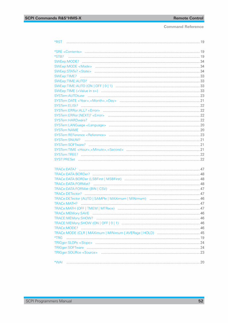
SCPI Commands ¸HMS-X Remote Control
52
Command Reference
SCPI Programmers Manual
*RST .......................................................................................................................................... 19
*SRE<Contents> ....................................................................................................................... 19*STB? ........................................................................................................................................ 19SWEep:MODE? .......................................................................................................................... 34SWEep:MODE<Mode> ............................................................................................................ 34SWEep:STATe?<State> ............................................................................................................. 34SWEep:TIME? ............................................................................................................................ 33SWEep:TIME:AUTO? .................................................................................................................. 33SWEep:TIME:AUTO {ON | OFF | 0 | 1} ....................................................................................... 33SWEep:TIME{<Valueins>} ...................................................................................................... 33SYSTem:AUTOtune .................................................................................................................... 23SYSTem:DATE<Year>,<Month>,<Day> ................................................................................... 21SYSTem:ELISt? ........................................................................................................................... 22SYSTem:ERRor:ALL?<Error> .................................................................................................... 22SYSTem:ERRor:[NEXT]?<Error> ............................................................................................... 22SYSTem:HARDware? ................................................................................................................. 22SYSTem:LANGuage<Language> .............................................................................................. 20SYSTem:NAME .......................................................................................................................... 20SYSTem:REFerence<Reference> .............................................................................................. 23SYSTem:SNUM? ....................................................................................................................... 21SYSTem:SOFTware? ................................................................................................................... 21SYSTem:TIME<Hour>,<Minute>,<Second> ............................................................................ 21SYSTem:TREE? ........................................................................................................................... 22SYST:PRESet .............................................................................................................................. 22
TRACe:DATA? ............................................................................................................................. 47TRACe:DATA:BORDer? ............................................................................................................... 48TRACe:DATA:BORDer {LSBFirst | MSBFirst} .............................................................................. 48TRACe:DATA:FORMat? .............................................................................................................. 48TRACe:DATA:FORMat {BIN | CSV} ............................................................................................. 47TRACe:DETector? ....................................................................................................................... 47TRACe:DETector {AUTO | SAMPle | MAXimum | MINimum} .................................................... 46TRACe:MATH? ........................................................................................................................... 47TRACe:MATH {OFF | TMEM | MTRace} ..................................................................................... 47TRACe:MEMory:SAVE ............................................................................................................... 46TRACE:MEMory:SHOW? ........................................................................................................... 46TRACE:MEMory:SHOW {ON | OFF | 0 | 1} ................................................................................. 46TRACe:MODE? ........................................................................................................................... 46TRACe:MODE {CLR | MAXimum | MINimum | AVERage | HOLD} ............................................ 45*TRG .......................................................................................................................................... 19TRIGger:SLOPe<Slope> ............................................................................................................ 24TRIGger:SOFTware ..................................................................................................................... 24TRIGger:SOURce<Source> ...................................................................................................... 23
*WAI .......................................................................................................................................... 20

© 2016 Rohde & Schwarz GmbH & Co. KG
Mühldorfstr. 15, 81671 München, Germany
Phone: +49 89 41 29 - 0
Fax: +49 89 41 29 12 164
E-mail: [email protected]
Internet: www.rohde-schwarz.com
Customer Support: www.customersupport.rohde-schwarz.com
Service: www.service.rohde-schwarz.com
Subject to change – Data without tolerance limits is not binding.
R&S® is a registered trademark of Rohde & Schwarz GmbH & Co. KG.
Trade names are trademarks of the owners.
5800.5776.02 │Version 02 │R&S®HMS-X
The following abbreviations are used throughout this manual: R&S®HMS-X is abbreviated as R&S HMS-X.