hmx pcu-f with control panel - a.t.e....
TRANSCRIPT

A.T.E. Enterprises Private Limited
Breathe Easy! Comfort Air Conditioning Solutions
Pre-cooling Unit – Fresh Air
Product Manual, Operation and Maintenance Instructions
HMX PCU-F with Control Panel
A high efficiency pre-cooler for improved IAQ (Indoor Air Quality)
Our coordinates:
A.T.E. Enterprises Private Limited,
A-422, 1St Cross, 1St Stage,
Peenya Industrial Area,
Bangalore – 560 058, Karnataka.
Phone : +91-80-2372 2326/2372 1065
Email : [email protected] / [email protected]
Website: www.hmx.co.in

A.T.E. Enterprises Private Limited (Business Unit: HMX)
About US:
A.T.E. Enterprises Private Limited (Business Unit: HMX) is located at Bengaluru, India, and designs and
manufactures unique, energy-efficient, and eco-friendly products for space and process cooling. We also undertake
turnkey projects for comfort air conditioning with our products as core. We provide environment friendly cooling
solutions that provide affordable comfort conditioning for people and also for processes.
The first of the innovative products that HMX has introduced is the HMX-Ambiator. Subsequently, we launched two
more products: PCU-F and PCU-R. The distinct features and benefits offered by the HMX’s products have made us the
preferred choice for cooling of large industrial and commercial spaces for people comfort and process cooling. HMX
has a proven track record of providing comfort air conditioning solutions in industries as varied as engineering and
beverages.
HMX now has an installation base of around 20 million CFM all over India. Our client base includes industries such as:
automobile and auto ancillaries, food and beverages, manufacturing, pharma, printing, packaging, IT, commercial
buildings, etc.
Some of our customers include ABB, Alkem, Amanora, Bilcare, Bosch, Coca Cola, Dabur, DB Group, Forbes Marshall,
GE, HAL, Himalaya, Honeywell, ICC Devi Gourav, ICRISAT, ITC, Kalpena Industries, Lupin, NRB, Pluss Polymer,
Relaxo, SKF, Suzlon, Syntel, Taj Hotels, Tata Motors, Teraspin, TVS, Victor Reinz, VW, Wipro, etc.
HMX’s strengths lie principally in:
Expertise in the domain of energy efficient air cooling
Fundamental understanding of human comfort, and of building modelling
In-house research and development for making continouous improvements in our products
Management and execution of projects for comfort air conditioning
Capability to modify existing cooling systems to enhance their cooling effect and energy efficiency
We have received recognition at various platforms. This includes three consecutive ‘ISHRAE Awards of Excellence’ for
the years 2010/2011/2012 in different categories, recognition by TERI, etc. The company was also nominated for the
“World Clean Energy Awards” under the products category at New York in May 2007.
Today, HMX works seamlessly with all units of the A.T.E. group, ensuring a country-wide sales, service, and project
management network.
Awards and Recognition:
2006 : Winner at the “Investor Forum” from World Resoucres Institute.
2007 : Nominated for “World Clean Energy Awards” under the products category.
2010 : Winner at ACREX INDIA, Under the “Green and Sustainable” category for HMX – Ambiator.
2011 : Winner at ACREX INDIA, Under the “Innovation” category for HMX – Economizer.
2012 : Winner at ACREX INDIA, “Awards of Excellence” for Indoor Air Quality on HMX – Treated Fresh Air (TFA).

A.T.E. Enterprises Private Limited (Business Unit: HMX)
TABLE OF CONTENTS Page. No
PRINCIPLE OF OPERATION OF PCU-F 2
Stage 1: Sensible Heat Exchanger (DAMA) 3
Stage 2: DX / Chilled Water Cooling Coil 3
DESCRIPTION OF THE PRODUCT – PCU-F 4
AHU Box 4
Water Tank With Heat Exchanger Supports 5
Main Blower And Motor 6
Heat Exchanger I (Sensible Heat Exchanger) 7
DX / Chilled Water Cooling Coil 8
Pumps And Water Distribution System 8
U-V Water Treatment Unit 9
Secondary Fans 10
Filters 11
Mist Eliminator 11
Control Panel 12
OPERATING INSTRUCTIONS 13
MAINTENANCE INSTRUCTIONS 15
General 16
Feed Water Quality 16
Tank And Heat Exchangers 16
Blower And Motor 16
Pumps 17

A.T.E. Enterprises Private Limited (Business Unit: HMX)
TABLE OF CONTENTS Page. No
U-V Treatment Unit 17
Filters 17
Electricals 17
MAINTENANCE SCHEDULE 18
Daily Schedule 18
Weekly Schedule 18
Monthly Schedule 18
Don’ts 18
TROUBLE SHOOTING CHART 19
SAFETY WARNING 21
Mechanical Components 21
Electrical Components 21
NO RISK OF LEGIONNAIRES’ 22
IMPORTANT INSTRUCTIONS 23
Annexure
Siemens Logo PLC Details

A.T.E. Enterprises Private Limited (Business Unit: HMX)
1
PRODUCT MANUAL
A.T.E. Enterprises Private Limited (Business Unit: HMX)
2
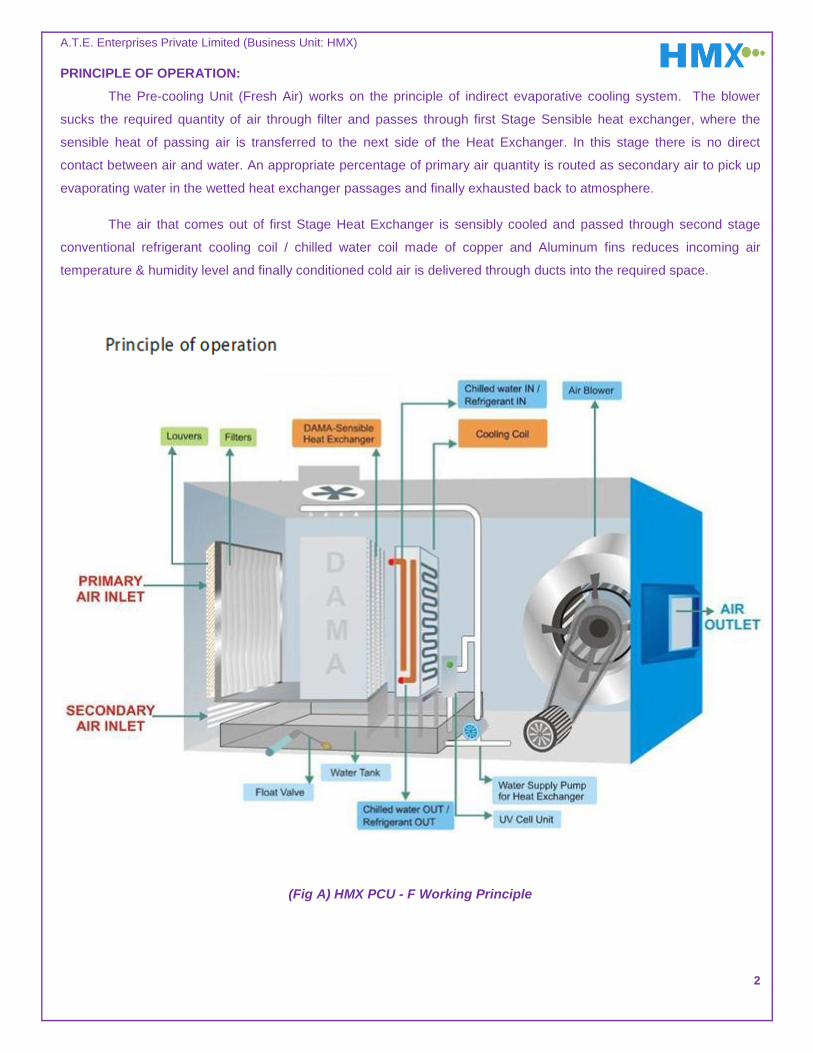
PRINCIPLE OF OPERATION:
The Pre-cooling Unit (Fresh Air) works on the principle of indirect evaporative cooling system. The blower
sucks the required quantity of air through filter and passes through first Stage Sensible heat exchanger, where the
sensible heat of passing air is transferred to the next side of the Heat Exchanger. In this stage there is no direct
contact between air and water. An appropriate percentage of primary air quantity is routed as secondary air to pick up
evaporating water in the wetted heat exchanger passages and finally exhausted back to atmosphere.
The air that comes out of first Stage Heat Exchanger is sensibly cooled and passed through second stage
conventional refrigerant cooling coil / chilled water coil made of copper and Aluminum fins reduces incoming air
temperature & humidity level and finally conditioned cold air is delivered through ducts into the required space.
(Fig A) HMX PCU - F Working Principle
A.T.E. Enterprises Private Limited (Business Unit: HMX)
3
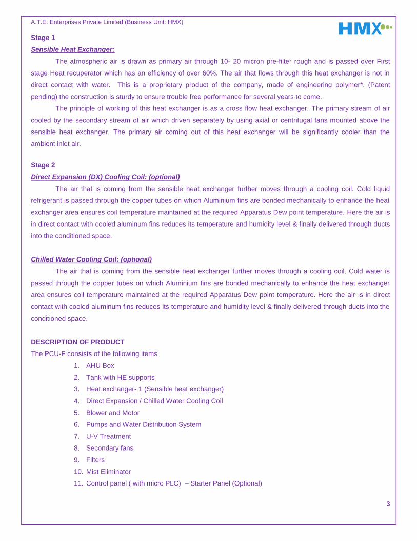
Stage 1
Sensible Heat Exchanger:
The atmospheric air is drawn as primary air through 10- 20 micron pre-filter rough and is passed over First
stage Heat recuperator which has an efficiency of over 60%. The air that flows through this heat exchanger is not in
direct contact with water. This is a proprietary product of the company, made of engineering polymer*. (Patent
pending) the construction is sturdy to ensure trouble free performance for several years to come.
The principle of working of this heat exchanger is as a cross flow heat exchanger. The primary stream of air
cooled by the secondary stream of air which driven separately by using axial or centrifugal fans mounted above the
sensible heat exchanger. The primary air coming out of this heat exchanger will be significantly cooler than the
ambient inlet air.
Stage 2
Direct Expansion (DX) Cooling Coil: (optional)
The air that is coming from the sensible heat exchanger further moves through a cooling coil. Cold liquid
refrigerant is passed through the copper tubes on which Aluminium fins are bonded mechanically to enhance the heat
exchanger area ensures coil temperature maintained at the required Apparatus Dew point temperature. Here the air is
in direct contact with cooled aluminum fins reduces its temperature and humidity level & finally delivered through ducts
into the conditioned space.
Chilled Water Cooling Coil: (optional)
The air that is coming from the sensible heat exchanger further moves through a cooling coil. Cold water is
passed through the copper tubes on which Aluminium fins are bonded mechanically to enhance the heat exchanger
area ensures coil temperature maintained at the required Apparatus Dew point temperature. Here the air is in direct
contact with cooled aluminum fins reduces its temperature and humidity level & finally delivered through ducts into the
conditioned space.
DESCRIPTION OF PRODUCT
The PCU-F consists of the following items
1. AHU Box
2. Tank with HE supports
3. Heat exchanger- 1 (Sensible heat exchanger)
4. Direct Expansion / Chilled Water Cooling Coil
5. Blower and Motor
6. Pumps and Water Distribution System
7. U-V Treatment
8. Secondary fans
9. Filters
10. Mist Eliminator
11. Control panel ( with micro PLC) – Starter Panel (Optional)

A.T.E. Enterprises Private Limited (Business Unit: HMX)
4
1. AHU BOX:
Air handling unit box consists of the following items.
Galvanized steel C-section with Aluminum die cast corner joints forms the machine base frame. The remaining
items of PCU-F are assembled on this frame. It is recommended to use rubber pads below the base frame in the
event of uneven platform in order to approximately level and balance the load of the machine.
Different Aluminum profiles namely corner and centre are used as the main skeleton which houses the double skin
panels in it. These aluminum profiles are joined by Nylon- corner and centre connectors. Blue color self adhesive
foam is fitted onto the profiles which houses the panels for air tightness of AHU box.
Double skin panels are fixed onto the aluminum profiles to conceal the blower, motor, heat exchangers, pump etc.,
to form a complete Air Handling Unit (AHU). The double skin panels made up of pre coated outer skin and plain
inner skin of GI 24 SWG or GI 22 SWG with 25mm or 50mm thick (refer the technical data sheet) which is filled
with Poly urethane foam (PUF) free from CFC.
The AHU is designed with access doors with viewing glass to ensure that all the parts are accessible for servicing,
inside a special reinforcement C channels are provided to strengthen the AHU casing to overcome the static
pressure.
The Air entry side wherein filters are fitted are protected with Louver covers onto the Aluminum profiles and is held
by Knobs and clamps (only in case of machines which are placed in open space. These louvers are made up of G
I material and powder coated.
The secondary air fans (centrifugal) are mounted on the GI flange in case of Axial fans and a plenum box (similar
to AHU box) for centrifugal fan.
The Air outlet of the machine has a GI flange to which the ducting can be connected.
(Fig 1.1) GI base frame (Fig 1.2) Nylon Three way Connector (Fig 1.3) Nylon End Connector

A.T.E. Enterprises Private Limited (Business Unit: HMX)
5
(Fig 1.4) Schematic
View of Panel
Assembly
2. TANK with HEAT EXCHANGER SUPPORTS:
Tank is made up of SS 304 sheet, which is leak proof. Provisions are given for water inlet, overflow and drain.
Tank is designed in such a way to ensure the complete drain of water in order to avoid water stagnation.
The tank houses the sensible and adiabatic heat exchanger modules, which are supported by SS 304 structural’s
(equal angle). It has a spray tank at the top where in water is sprinkled on the sensible heat exchanger modules.
The adiabatic heat exchanger is kept wet by water sprinkler system that is housed in a hood at the top.
The tank is fitted with a float valve for maintaining the level of water in the tank. Also water level sensor is fitted in
the tank to ascertain the level of water and send feedback signal to the control circuits in case of low water level.
(Fig 2.1) Tank with Heat Exchanger Base Supports (Fig 2.2) Tank with Heat Exchanger Frames

A.T.E. Enterprises Private Limited (Business Unit: HMX)
6
3. MAIN BLOWER AND MOTOR:
This is an important component of an PCU-F. The blower used in an PCU-F is a dynamically balanced centrifugal
blower.
(Fig 3.1) Blower – Motor Assembly
The Blower-Motor is assembled on aluminum blower rails which are assembled in perpendicular directions. The
blower is fixed on one set of rails and the motor on second set which is fixed perpendicular to it.
The blower supporting rails are mounted on Vibration isolators, which are fixed to the bottom of the AHU box on
aluminum rails, so that the dynamic load of the Blower motor combination does not transfer the vibration to the
AHU box during running of the Blower.
The motor is fixed onto a GI saddle (Motor Base Plate) with which the belt tensioning can be adjusted easily by
moving the motor on saddle and then locked.
The mouth of the blower is fitted with a canvas connection, the other end of which is fixed to the AHU box
aluminum profile, so that any vibration in the blower motor combination is not transferred to the box. By this the
dynamic blower motor combination during running is totally isolated from transfer of any vibration.

A.T.E. Enterprises Private Limited (Business Unit: HMX)
7
4. HEAT EXCHANGER-1: DAMA (SENSIBLE HEAT EXCHANGER):
The principle of working of this heat exchanger is as a cross flow heat exchanger.
(Fig 4.1) Schematic view of DAMA (Sensible Heat Exchanger)
The primary stream of air passes thru the flutes of the heat exchanger and secondary stream moves in the
perpendicular direction in the passages of the heat exchanger ,thus exchanging heat thru’ the sheet barrier. The
heat exchange is further improved by keeping the surface of the sheet wet and evaporating the thin film of water by
moving secondary air. The movement of primary air is by centrifugal fan and secondary air is by either axial or
centrifugal fan depending on the machine configuration.
The heat exchanger (DAMA) is made of an Engineering Polymer and has an efficiency of > 60%. The air that flows
through this heat exchanger is not in direct contact with water. This is a proprietary product of the company*.
(Patent pending) the construction is sturdy to ensure trouble free performance for several years to come.
Sensibly cooled air from
DAMA

A.T.E. Enterprises Private Limited (Business Unit: HMX)
8
5. DIRECT EXPANSION / CHILLED WATER COOLING COIL:
Internally grooved copper tubes are mechanically expanded to fit into the Aluminium sinusoidal slit fins to form a
cooling coil.
Cold liquid refrigerant/ water is passed through internally grooved copper tubes which intern maintain fin
temperature at apparatus dew point temperature causing incoming air stream to lose sensible and latent heat to
refrigerant / chilled water. Dehumidified and cooled air is passed through ducts to conditioned space.
(Fig 5.1) DX / Chilled Water Cooling Coil
6. PUMPS AND WATER DISTRIBUTION SYSTEM:
Individual pumps are used to lift water from the tank to the top surface of Heat exchangers- both Sensible and
Adiabatic. The water which is lifted is uniformly sprayed thru’ ‘water distribution system’ onto the top surface,
which comes back to tank by gravity thus wetting the surfaces of heat exchanger.
Either Monoblock or Submersible pumps are used for recirculation of water from the tank continuously thereby
wetting the Heat exchangers to the required levels. Pump has a suction strainer in case of Monoblock, thru’ which
water is sucked. The distribution from the delivery side in each pump is different. Pump 1 and 2-supply water to HE
1 & 2 respectively, which distributes water on the top surface.
The water flow is controlled by gate valves so as to maintain the required wetness of the Heat exchangers. In case
of excess water, provisions are made to bypass it back to the tank.
After careful study, flow rate of the water will be adjusted to required level at the time of commissioning. This
should not be disturbed at any point of time unless other parameters like temp and humidity is to be altered.
The delivery of the pump 1 to Sensible Heat exchangers is branched into 2 lines and is controlled by gate valves.
First line goes to the top tier of Heat exchanger whose distribution pipeline is assembled to spray the water
uniformly on the top surface of the HE cartridges thereby wetting the surface.
Second line is the bypass line, wherein excess amount of water is diverted back into the tank thus
balancing the water on the heat exchanger, without overloading the motor of the pump.
Third line is the bypass line, wherein excess amount of water is diverted back into the tank thus balancing
the water on the heat exchanger, without overloading the motor of the pump.

A.T.E. Enterprises Private Limited (Business Unit: HMX)
9
This flow rate is adjusted to see that pads are uniformly wet and water quantity can be varied by means of gate
valve depending on the saturation required. Higher the saturation greater will be the temperature drop in turn
increasing the humidity. This Water flow rate is set depending on the end condition required.
NOTE: The Bleed off water can be planned on request, provided the customer needs the same. The bleed off water quantity will be
calculated based on the salts in the water, which has to be provided.
7. U-V WATER TREATMENT UNIT:
U.V Water treatment unit is provided in the machine to remove the bacteria in the water and purify the water.
This unit will be operative so long as the machine is running, so that continuous recirculation of water will keep the
water free from micro organisms. The tank water circulates in the U V Unit thru’ the outlet in pump2. This is
connected by thru’ one line of pump by nylon braided ½” pipe and the water is continuously put back to the tank at
the rate of 250lts/hr. The unit is built on the property of UV radiation at 2537-Angstrom units capable of striking
bacteria, algae, fungi and protozoa and rendering them harmless.
(Fig 7.1) Schematic View of UV Water Treatment Unit
The UV unit is made up of SS 304 with high efficiency UV lamp surrounded by Crystal glass sleeve to isolate the
bulb from water contact preventing thermal shock, glass breakage and mercury contamination. The sleeve also
ensures very high transmission of UV energy with lesser losses. The bulb with sleeve is accommodated in
precision-engineered SS square tube which is closed on either side and has an ½” collars for connecting nylon
braided pipe thru’ hose nipple. The water enters from bottom connector and comes out thru top connector back
into the tank. This entire assembly is housed in a powder coated box, with outside indicating lamps to show the
working of the unit.
An Electronic Ballast operating on 230 V, single phase 50 Hz AC triggers the UV bulb and ensures minimum
power consumption. The design is based on 30000-microwatt sec/sq.cm dosage of UV radiation, which destroys
significant water borne pathogenic microorganisms effectively.

A.T.E. Enterprises Private Limited (Business Unit: HMX)
10
8. SECONDARY FANS: (applicable in case of draw through type machine)
Secondary fan is of Centrifugal” type based on the design conditions and requirements. This is indicated in the
Technical Specification sheet. Selection of blower and motor depends on static pressure and power required to
drive the secondary air (refer technical data sheet).
In centrifugal type, Secondary fan assembly with motor is assembled on a straddle which is sufficiently rigid to
house the Blower /Motor combination, with provision for belt tensioning.
The assembly is enclosed in a plenum which is air tight and the fan draws air thru ‘the passages in the sensible
heat exchanger – DAMA and is thrown out. In case the machine is kept inside an AHU room the secondary air has
to be ducted out, otherwise it can be protected with a cowl having bird mesh and thrown into atmosphere.
Plenum casing provides a protection against rain and external agents falling on the secondary fan. Service door
with marine lamp inside the casing helps for maintenance.
(Fig 8.2) Secondary Fan with plenum casing – Centrifugal Type (optional)
Secondary Air from
DAMA

A.T.E. Enterprises Private Limited (Business Unit: HMX)
11
9. FILTERS:
Pre-Filters: The efficiency of pre-filters is 90% down to the range of 20 microns. The filter comprises a high quality
synthetic media made of HDPE pleated with Aluminum mesh and housed in GI casing which filters the incoming
air with media. The filtered air then passes through further filtration (optional) and then goes to Heat exchangers
HE 1 and HE 2. All pre filters are either washable or cleanable.
Fine-Filters(Optional): The fine filters are made from selected hi-quality non woven synthetic felt (Needle
punched filter media) supported by HDPE mesh, suitable for arresting 5 micron of dust present in the
environment. The filter media is stitched and pleated together to provide maximum filtration area in the space
provided & finally housed in a galvanized frame. The fine filters are completely washable / cleanable.
(Fig 9.1) Panel Filters (Fig 9.2) Flange Filters
10. MIST ELIMINATOR:
Mist Eliminator helps to prevent water from the Heat Exchanger to be carried into the air stream, which will have
adverse effects on indoor air quality and can compromise System operation and maintenance.
HMX mist eliminator panels require minimal space and offer low pressure drops. It is designed to mount easily
inside the frame in front of the Heat Exchanger.
Mist/Water particle removed from the air stream drops down to a drain pan and is taken back into the main tank.
(Fig 10.1) HMX Make Mist Eliminator

A.T.E. Enterprises Private Limited (Business Unit: HMX)
12
11. CONTROL PANEL (with micro PLC): Optional
HMX control panel is a cabinet type made of 18swg CRCA sheet and powder coated. Electrical hardware in
mounted on a 10swg CRCA mounting plate which is painted and this is assembled into the cabinet box, after
assembly of the elements. The front door of the cabinet houses the pilot lamps, on /off push button,
microcontroller etc.
Each motor contactor contains an overload relay (OLR) protection to protect the motor in case of high current
supply.
Miniature Circuit Breakers are provided to prevent extensive damage due to short-circuits in power and control
circuits.
Pre-programmed micro PLC is to control the hassle free operation of PCU-F. Refer annexure for more details.
NOTE: Appropriate circuit diagram & Specification sheet is attached as annexure to this manual.
A.T.E. Enterprises Private Limited (Business Unit: HMX)
13
PRE-COOLING UNIT
(FRESH AIR)
OPERATION

A.T.E. Enterprises Private Limited (Business Unit: HMX)
14
OPERATIONS OF THE PRECOOLING UNIT (FRESH AIR)
PCU-F is supplied along with a control panel for operating machine as per needs of the customer. Factory
trained technicians will assemble and commission the machine before it is handed over to the user.
Daily switching ON/OFF of the machine the below procedure has to be followed:
Ensure that the Voltage and water supply are as per the requirement for starting the machine. The machine will not
switch ON over two conditions, in case:
1. The water level is not maintained in the tank. Under
2. The service door is open.
Switch the isolator switch to ON position provided in the control panel to supply power to the control panel.
Indication of Power ON is indicated thru’ a lamp on control panel.
Machine can be switched on, in two modes. Viz. Auto / Manual which is done by a selector switch.
Keep the machine in Auto Mode and switch ON the machine by pressing the Push button.
Machine is switched ON and internally it follows the below sequence with the help of Microcontroller.
The pumps will be ON in at the first place which is indicated by the illuminated green pushbutton.
There is a delay time before the Blower comes to ON condition, simultaneously the secondary fans will also come
to ON condition with indication in the illuminated green pushbutton.
NOTE: Machines starts to move air thru’ the outlet flange/damper which has to be kept in open condition (or set condition).
The sensors which are placed in the conditioned space senses the Temperature / Relative Humidity and controls the
switching ON/OFF of the Blower and Pumps according to the setting done in the Micro PLC.
In case the machine under repair it can be operated in Manual mode. This bye passes all the sequences listed above
and individually the pumps, blower, secondary fans can be switched on with the push button and made to operate.

A.T.E. Enterprises Private Limited (Business Unit: HMX)
15
PRE-COOLING UNIT
(FRESH AIR)
MAINTENANCE

A.T.E. Enterprises Private Limited (Business Unit: HMX)
16
PCU-F MAINTENANCE INSTRUCTIONS:
GENERAL:
HMX PCU-F is designed for easy maintenance, with highest quality materials and components used throughout.
Preventative maintenance programs will vary according to actual working conditions and location and hours of
usage by the client.
HMX is pleased to provide expert advice on special service requirements for particular installations.
Note: To guarantee trouble free operation of this evaporative cooler, the manufacturer suggests following the below mentioned
guidelines. Most problems associated with unit failures are directly related to poor service and maintenance.
FEED WATER QUALITY:
Water supplied to the HMX PCU-F should be clean and devoid of sediments. Hardness of the water has to be less
than 500PPM. This improves life of the heat exchangers, pumps, pipes and fittings.
Line pressure for make-up should be less than 1 bar. If higher than 1 bar, a PRV is recommended to reduce the
inlet pressure to less than 1 bar.
Scale formation in heat exchangers, pipes, etc. can be removed by adding “Scale guard” solution in the water tank.
Periodicity depends on quality of water and is recommended once in 6–12 months, depending of the quality of
water.
Carry out periodic biological tests of water supplied to PCU-F in case quality of water in your area is suspect.
TANK AND HEAT EXCHANGERS:
Water tank to be drained and cleaned once in a month to avoid debris / sediment formation and clogging of
pumps, pipes, etc. Maintain a suitable water bleed-off periodicity to ensure that sedimentation is kept minimal.
Once every 9 to 12 months the tank and Heat exchangers to be cleaned by adding formic acid to the water
tank in 0.2% concentration with water. This is to prevent bacteria, mites, bugs etc. And the pumps will be run for 2
hours thereby ensuring that the HE and Tank is subjected to the acid. Then the water is drained completely and fresh
water filled.
Heat exchanger pads should be allowed to dry out every 24 hours whist blower is running. This helps curb
algae and bacteria growth.
BLOWER AND MOTOR:
Once in a month check that blowers and motors are working normally; belt tensioning is proper and also
lubricates bearings periodically. More details are given in respective maintenance manuals of blowers and motors.
Anti-rust coat is to be applied to exposed areas of blower and motor shafts, pulleys, etc. This is to be done at
least once in 6 months or more often, if required.

A.T.E. Enterprises Private Limited (Business Unit: HMX)
17
PUMPS:
The pumps used in the machine is either Monoblock or submersible type (refer the annexure). For
maintenance refer the instructions sheet of the Pump enclosed.
Water supply pumps tend to jam if not used for long periods of time. In case PCU-F is to be switched on after
shut down for more than 3 days, check water supply pumps to ensure that they rotate freely and are not “jammed.
In case of monoblock pump, please ensure that the pump casing is filled with water before starting. Clean the
suction strainer once in 15 days initially in order to see that no clogging is there. In case there is no water deliveries
first check the suction strainer for clogging. Check for and stop leaks, if any, in the water distribution system.
U-V TREATMENT UNIT:
The performance of the UV treatment unit diminishes with time due to electrode degradation occurring every
time the UV lamp is cycled on and off. Average life period of the lamp is approximately 8800 hours or one year.
During the period of working, there is a chance of formation of a thin film of organic and inorganic substances
around the sleeve which will reduce the disinfection effectiveness. The sleeve which transfers the radiation should be
cleaned one in 3 months so that radiation efficiency will not reduce.
Once in 3 months the drain plugs of the unit to be removed and water to be drained out. This has to be done at
the time of cleaning the sleeve. The frequency of this cleaning will be dependent on the quality of the water passing
through the UV unit.
FILTERS:
Cleaning of filters is recommended to avoid choking which results in poor performance of the PCU-F. Check
the filters for dust accumulation. Dust accumulation varies with location of installation.
In general, Filter is made up of HDPE mesh, which is easily cleanable. It can be done either by water spray or
compressed air. The filter has to be removed from the machine by opening the clamps and cleaned thoroughly with
water or air to remove the foreign particles sticking to it (Dry it completely before fixing). This can be done once in one
month. However the periodicity will be finalized after first 3 months of observation.
ELECTRICAL:
Switch off the main incomer when the PCU-F is not in use.
Ensure that doors of the PCU-F are closed properly before start. A limit switch is provided on the PCU-F door to
prevent working of PCU-F in case door is open.
UV filtration system in the PCU-F is provided with indicator lamps. Check periodically and ensure replacement of
UV lamps accordingly.
Always disconnect line voltage before servicing electrical equipment.
Ensure there are no loose electrical connections at regular maintenance intervals.

A.T.E. Enterprises Private Limited (Business Unit: HMX)
18
MAINTENANCE SCHEDULE:
Daily:
Check the Power on Indication
Check the water level
Make up water line pressure should be less than 1 bar
Check the doors are closed properly
Check the filters for Dust accumulation
Switch off the Main incomer when not in use
Drain and refill water if shut down is more than 48 hrs
Check for any abnormal noise
Keep the area clean
Weekly:
Check Air filter for dust accumulation
Check the Belt tension
Check for any abnormal noise
Monthly:
Clean the Filters (MORE OFTEN IF REQUIRED)
Water tank to be drained and cleaned (MORE OFTEN IF REQUIRED)
Apply thin layer of grease on the periphery of the blower shaft and Exposed portion (fascia) of pulley
Check and maintain proper pulley alignment and belt tension
Check and tighten motor mount bracket and bolts as required.
Check bearings for wear.
Don’ts
Don’t disturb the water line bye pass settings
Don’t Run the Pump without sufficient water in the Tank
Don’t open the door when unit running
Don’t power on the system with panel door in opened condition
Don’t open the Bus bar panel without switching off the main incomer
A.T.E. Enterprises Private Limited (Business Unit: HMX)
19
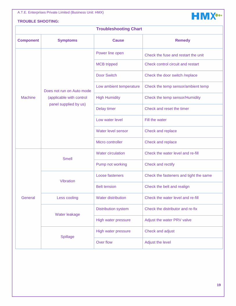
TROUBLE SHOOTING:
Troubleshooting Chart
Component Symptoms Cause Remedy
Machine
Does not run on Auto mode
(applicable with control
panel supplied by us)
Power line open Check the fuse and restart the unit
MCB tripped Check control circuit and restart
Door Switch Check the door switch /replace
Low ambient temperature Check the temp sensor/ambient temp
High Humidity Check the temp sensor/Humidity
Delay timer Check and reset the timer
Low water level Fill the water
Water level sensor Check and replace
Micro controller Check and replace
General
Smell
Water circulation Check the water level and re-fill
Pump not working Check and rectify
Vibration
Loose fasteners Check the fasteners and tight the same
Belt tension Check the belt and realign
Less cooling Water distribution Check the water level and re-fill
Water leakage
Distribution system Check the distributor and re-fix
High water pressure Adjust the water PRV valve
Spillage
High water pressure Check and adjust
Over flow Adjust the level
A.T.E. Enterprises Private Limited (Business Unit: HMX)
20
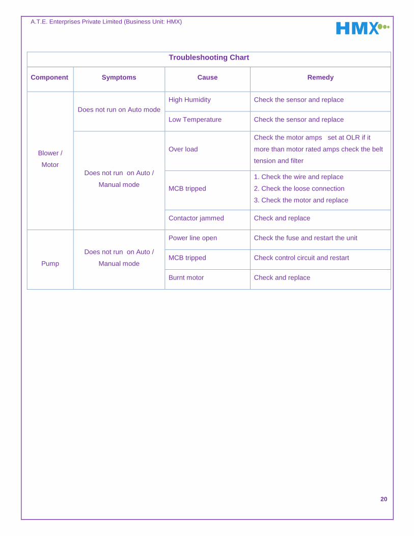
Troubleshooting Chart
Component Symptoms Cause Remedy
Blower /
Motor
Does not run on Auto mode
High Humidity Check the sensor and replace
Low Temperature Check the sensor and replace
Does not run on Auto /
Manual mode
Over load
Check the motor amps set at OLR if it
more than motor rated amps check the belt
tension and filter
MCB tripped
1. Check the wire and replace
2. Check the loose connection
3. Check the motor and replace
Contactor jammed Check and replace
Pump
Does not run on Auto /
Manual mode
Power line open Check the fuse and restart the unit
MCB tripped Check control circuit and restart
Burnt motor Check and replace

A.T.E. Enterprises Private Limited (Business Unit: HMX)
21
SAFETY AND WARNING:
MECHANICAL COMPONENTS:
Warning: Switch off the PCU-F before attempting to clean.
Filters must be changed / cleaned regularly to ensure airflow is unrestricted. Never operate the HMX PCU-F without
filters. Unfiltered air can damage the Sensible Heat Exchanger may invalidate our warranty.
Clean the tank according to the maintenance schedule to avoid debris formation and dust sedimentation.
Do not attempt to change/clean the heat exchanger without the proper guidance from HMX. This can mean that the
media between the polymer plates is dislodged from its position and therefore will have an effect on the performance of
heat exchanger. Any tampering with the heat exchanger may invalidate our warranty and HMX will not be held
responsible for lack of performance.
ELECTRICAL COMPONENTS:
Warning: Ensure that power is switched off and unplugged before servicing electrical equipment. Ensure there
are no loose electrical connections at services intervals.
Do not run the pump dry to avoid the damage to mechanical seal
Failure to carry out regular maintenance with a qualified service professional may render warranty claims invalid if
faults have been caused by lack of proper maintenance.
HMX Systems may request to see the maintenance schedule carried out.
Note: HMX Systems can provide AMC upon request.

A.T.E. Enterprises Private Limited (Business Unit: HMX)
22
LEGIONELLOSIS IS NOT A RISK:
There have been no known cases of Legionnaire’s disease with air washers, wetted media evaporative air
coolers1. This is mainly because the temperature of the water, i.e. wet bulb temperature, is below 25°C.
The incidence of Legionellosis when using HMX PCU-Fs is further reduced by following the recommendations laid
out in ASHRAE’s guideline and position paper2: PCU-Fs are designed and located:
o Intake air filters upstream of the heat exchanger to remove dust particles above 5 or 10 microns with
removal efficiency of over 90% to avoid carry-over of air-borne dirt particles.. Filters must be cleaned as
per recommended schedule.
o Lower rates of build-up of scale and sludge in water tank by maintaining a constant bleed-off and
periodically draining the tank contents.
o Continuous UV treatment of water that is circulated to ensure disinfection of circulating water
Inlet sections for PCU-Fs are not located near cooling towers.
Ensure make-up water is treated to remove microbial contamination before it is used in PCU-F.
1 ASHRAE guideline 12-2000 “Minimizing the Risk of Legionellosis Associated with Building Water Systems”
2 ASHRAE guideline 12-2000 “Minimizing the Risk of Legionellosis Associated with Building Water Systems”

A.T.E. Enterprises Private Limited (Business Unit: HMX)
23
For any service related request / query
Please contact us at: [email protected]
Mobile: +91 – 88848 99888
IMPORTANT
Do not supply the water with more than 1 bar pressure. This will cause malfunctioning / failure of
the float valve provided inside the machine, leading to water leakage.
Hardness of the supply water should not exceed more than 500 PPM of CaCo3 level and will have
an increased life of the PCU-F.
If the PCU-F is stopped for more than 3 days, ensure that water in the tank is completely drained.
Before re-starting the PCU-F, clean the tank and re-fill the tank with water. This also helps avoid
bad odour due to dampness of the Celdek pads.
For longer life of the PCU-F it is advisable to bleed / drain off water periodically. This will ensure
better life of Heat exchanger by avoiding salt deposition and blocking the passage of air.