høgskolen i telemark telemark university college¸gskolen i telemark telemark university college!...
TRANSCRIPT
Høgskolen i Telemark Telemark University College Department of Electrical Engineering, Information Technology and Cybernetics
Faculty of Technology, Postboks 203, Kjølnes ring 56, N-3901 Porsgrunn, Norway. Tel: +47 35 57 50 00 Fax: +47 35 57 54 01
Wi-‐Fi DAQ
Hardware Setup Cuong Nguyen, Hans-‐Petter Halvorsen, 2013.08.07

2
Table of Contents 1 Introduction ...................................................................................................................................... 3
1.1 Necessary Equipment ................................................................................................................ 4
2 Technical Implementation ................................................................................................................ 5
2.1 Step1: Physical Connection ....................................................................................................... 5
2.2 Step 2: NI WAP-‐3711 Configuration .......................................................................................... 6
2.3 Step 3: NI WLS-‐9163 Configuration ........................................................................................... 9
2.4 Step 4: Computer Configuration ............................................................................................. 13
2.5 Step 5: Temperature Presentation .......................................................................................... 16
3 Summary ......................................................................................................................................... 19
3
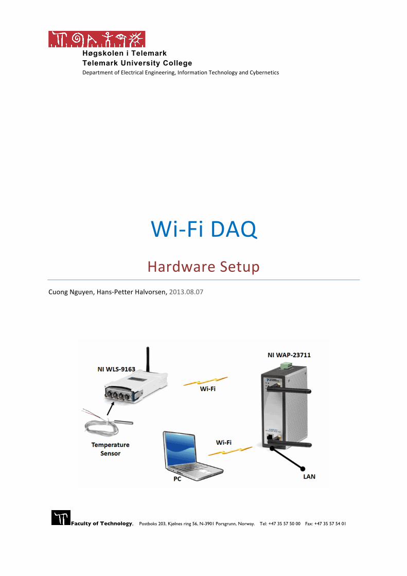
1 Introduction This tutorial will go through how to transfer data acquired from a sensor to the computer wirelessly by using a Wi-‐Fi DAQ system. The data transmission relies on National Instruments technology, where NI WAP-‐3711 will broadcast wireless internet from TUCs LAN. This documentation is created based on experiment by using the following equipment:
• Hardware Ø Temperature sensor PT-‐100 Ø Transducer board Ø Wi-‐Fi equipment
- NI WAP-‐3711 (802.11g/b WAP/Bridge/Client) - NI WLS-‐9163 (802.11g/b C Series Carrier) - NI 9234 (DAQ)
• Software Ø Windows OS Ø LabVIEW Ø NI-‐DAQmx (MAX)
The data transferring procedure through Wi-‐Fi (Infrastructure) technology involves mainly five different steps;
Step 1: Physical devices, setup and connection. Devices: NI-‐WLS-‐9163, NI9234 (DAQ) and connection board shall be physically connected to each other.
Step 2: NI WAP-‐3711 configuration. Set up and configure NI WAP-‐3711 to manage the wireless data communication between the computer and NI WLS-‐9163 device.
Step 3: NI WLS-‐9163 configuration. Set up and configure NI WLS-‐9163 to transmit temperature values to NI WAP-‐3711.
Step 4: Configure your computer to get access to NI WAP-‐3711.
Step 5: Present the temperature value on the computer. Create a LabVIEW application to continuously retrieve and present the value on your computer. The acquired values are originally in Voltage format which needs to be converted into corresponding temperature.
4 Introduction
Wi-Fi DAQ - Hardware Setup
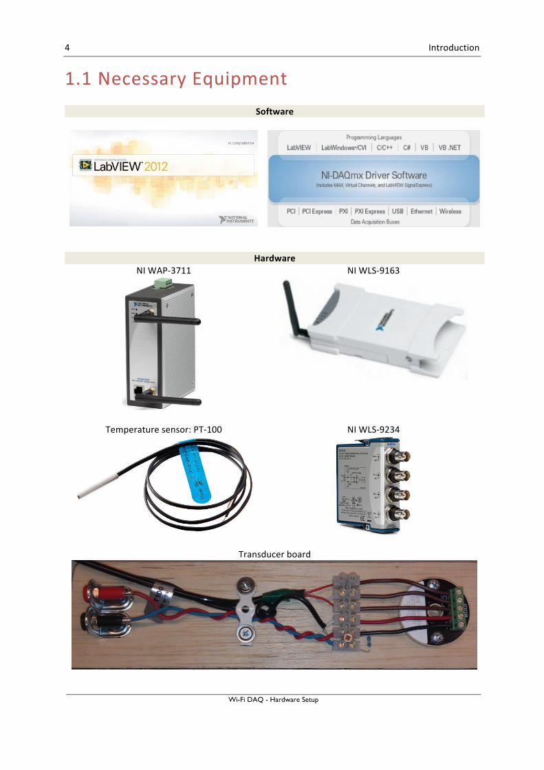
1.1 Necessary Equipment Software
Hardware NI WAP-‐3711
NI WLS-‐9163
Temperature sensor: PT-‐100
NI WLS-‐9234
Transducer board
5
2 Technical Implementation This section will explain the data acquiring process in details, which covers all the involving five steps stated above. By following the instructions, as the result temperature values obtained by the temperature sensor (PT-‐100) will be presented on the computer screen wirelessly. Wi-‐Fi (infrastructure) is the technology behind the wireless data transferring procedure. Here we use NI WAP-‐3711 to broad cast wireless network, which is based on TUCs LAN. The wireless network (Eduroam) offered by TUC is heavily encrypted and has a lot of restrictions, by creating our own WAP data transmitted will be more flexible and give us more possibilities.
2.1 Step1: Physical Connection PT-‐100 is a temperature sensor based on resistance (Ω) which various in corresponding to the changing in temperature. This element cannot be connected directly to the NI 9234 (DAQ) module because it requires input as Voltage. Due to this reason the two elements can only have communications with each other through the “transducer board”. Additionally, both of the devices NI 9234 (DAQ) and NI WLS-‐9163 are needed to be attached to each other as one single physical component.
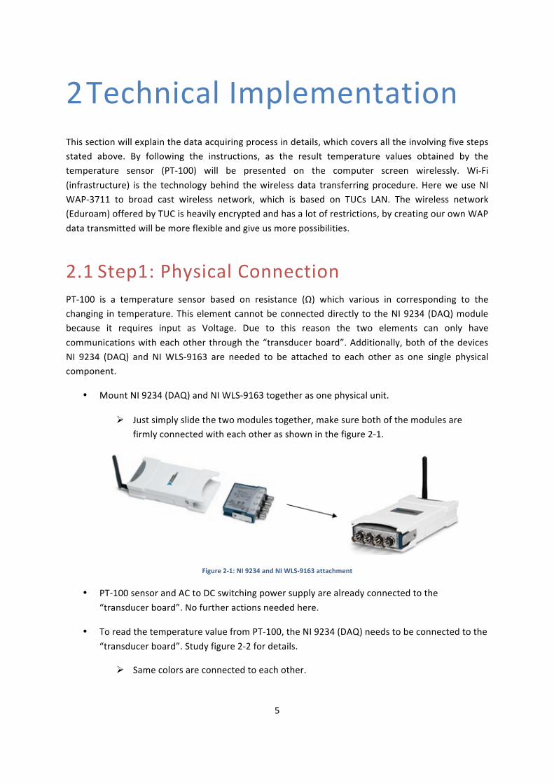
• Mount NI 9234 (DAQ) and NI WLS-‐9163 together as one physical unit.
Ø Just simply slide the two modules together, make sure both of the modules are firmly connected with each other as shown in the figure 2-‐1.
Figure 2-‐1: NI 9234 and NI WLS-‐9163 attachment
• PT-‐100 sensor and AC to DC switching power supply are already connected to the “transducer board”. No further actions needed here.
• To read the temperature value from PT-‐100, the NI 9234 (DAQ) needs to be connected to the “transducer board”. Study figure 2-‐2 for details.
Ø Same colors are connected to each other.
6 Technical Implementation
Wi-Fi DAQ - Hardware Setup
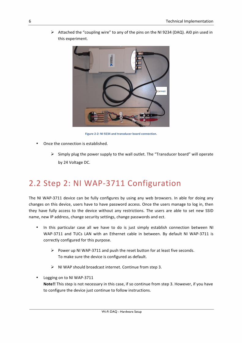
Ø Attached the “coupling wire” to any of the pins on the NI 9234 (DAQ). AI0 pin used in this experiment.
Figure 2-‐2: NI 9234 and transducer board connection.
• Once the connection is established.
Ø Simply plug the power supply to the wall outlet. The “Transducer board” will operate
by 24 Voltage DC.
2.2 Step 2: NI WAP-‐3711 Configuration The NI WAP-‐3711 device can be fully configures by using any web browsers. In able for doing any changes on this device, users have to have password access. Once the users manage to log in, then they have fully access to the device without any restrictions. The users are able to set new SSID name, new IP address, change security settings, change passwords and ect.
• In this particular case all we have to do is just simply establish connection between NI WAP-‐3711 and TUCs LAN with an Ethernet cable in between. By default NI WAP-‐3711 is correctly configured for this purpose.
Ø Power up NI WAP-‐3711 and push the reset button for at least five seconds. To make sure the device is configured as default.
Ø NI WAP should broadcast internet. Continue from step 3.
• Logging on to NI WAP-‐3711 Note!! This step is not necessary in this case, if so continue from step 3. However, if you have to configure the device just continue to follow instructions.
7 Technical Implementation
Wi-Fi DAQ - Hardware Setup
Ø Connect your computer to NI WAP-‐3711 by using Ethernet cable (straight-‐through or cross-‐over cable)
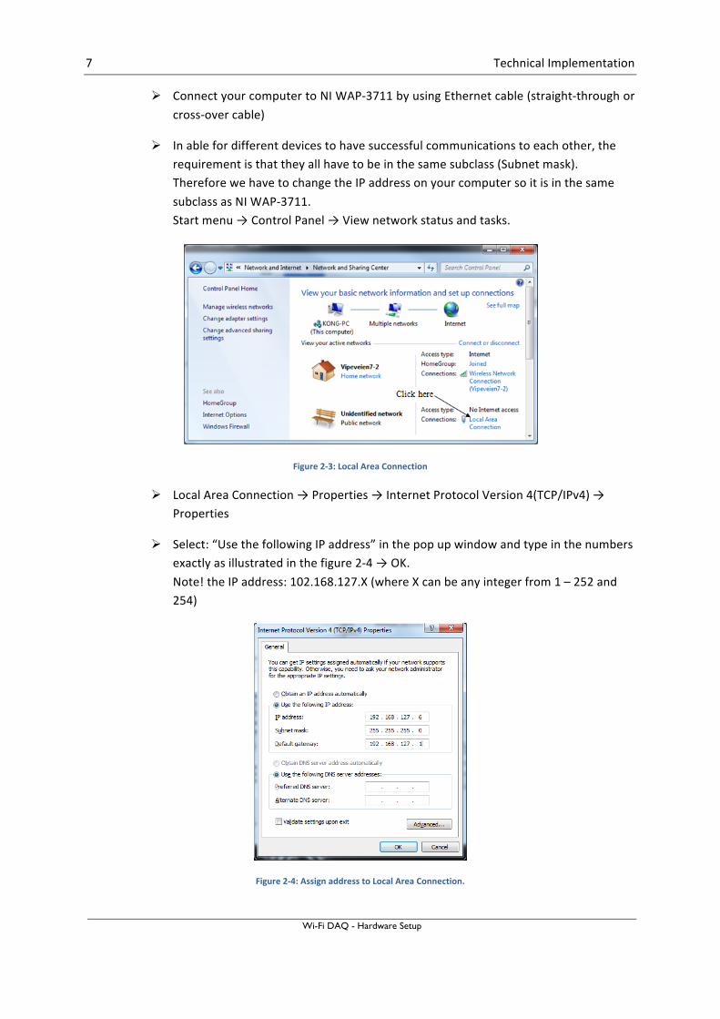
Ø In able for different devices to have successful communications to each other, the requirement is that they all have to be in the same subclass (Subnet mask). Therefore we have to change the IP address on your computer so it is in the same subclass as NI WAP-‐3711. Start menu → Control Panel → View network status and tasks.
Figure 2-‐3: Local Area Connection
Ø Local Area Connection → Properties → Internet Protocol Version 4(TCP/IPv4) → Properties
Ø Select: “Use the following IP address” in the pop up window and type in the numbers exactly as illustrated in the figure 2-‐4 → OK. Note! the IP address: 102.168.127.X (where X can be any integer from 1 – 252 and 254)
Figure 2-‐4: Assign address to Local Area Connection.
8 Technical Implementation
Wi-Fi DAQ - Hardware Setup
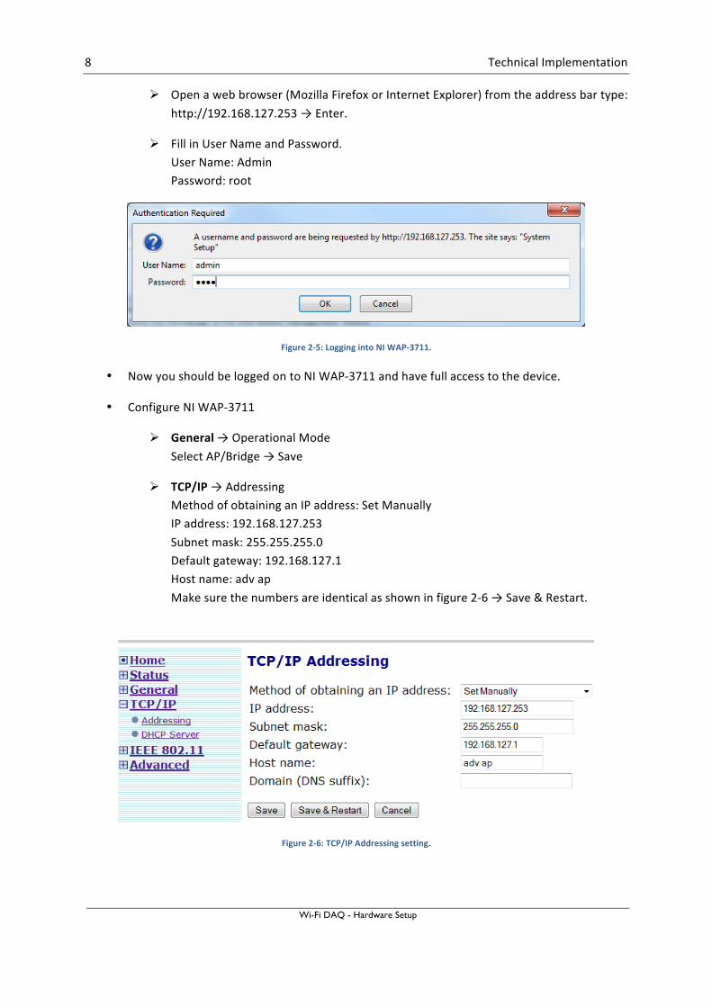
Ø Open a web browser (Mozilla Firefox or Internet Explorer) from the address bar type: http://192.168.127.253 → Enter.
Ø Fill in User Name and Password. User Name: Admin Password: root
Figure 2-‐5: Logging into NI WAP-‐3711.
• Now you should be logged on to NI WAP-‐3711 and have full access to the device.
• Configure NI WAP-‐3711
Ø General → Operational Mode Select AP/Bridge → Save
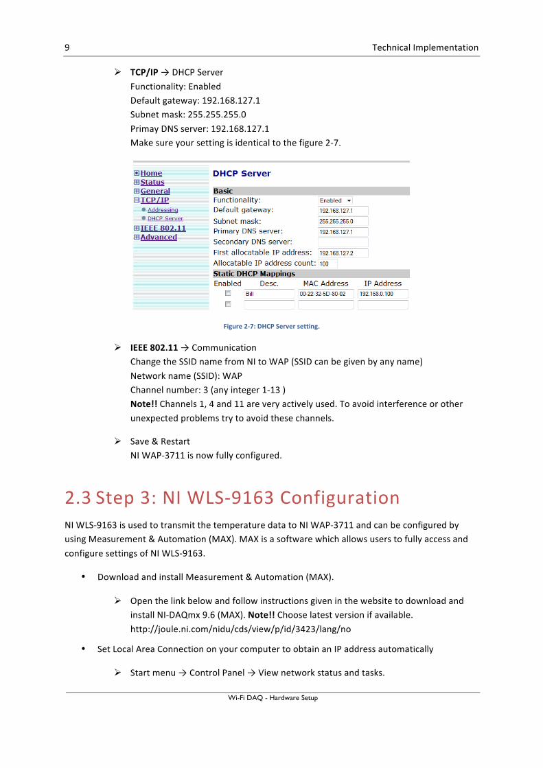
Ø TCP/IP → Addressing Method of obtaining an IP address: Set Manually IP address: 192.168.127.253 Subnet mask: 255.255.255.0 Default gateway: 192.168.127.1 Host name: adv ap Make sure the numbers are identical as shown in figure 2-‐6 → Save & Restart.
Figure 2-‐6: TCP/IP Addressing setting.
9 Technical Implementation
Wi-Fi DAQ - Hardware Setup
Ø TCP/IP → DHCP Server Functionality: Enabled Default gateway: 192.168.127.1 Subnet mask: 255.255.255.0 Primay DNS server: 192.168.127.1 Make sure your setting is identical to the figure 2-‐7.
Figure 2-‐7: DHCP Server setting.
Ø IEEE 802.11 → Communication Change the SSID name from NI to WAP (SSID can be given by any name) Network name (SSID): WAP Channel number: 3 (any integer 1-‐13 ) Note!! Channels 1, 4 and 11 are very actively used. To avoid interference or other unexpected problems try to avoid these channels.
Ø Save & Restart NI WAP-‐3711 is now fully configured.
2.3 Step 3: NI WLS-‐9163 Configuration NI WLS-‐9163 is used to transmit the temperature data to NI WAP-‐3711 and can be configured by using Measurement & Automation (MAX). MAX is a software which allows users to fully access and configure settings of NI WLS-‐9163.
• Download and install Measurement & Automation (MAX).
Ø Open the link below and follow instructions given in the website to download and install NI-‐DAQmx 9.6 (MAX). Note!! Choose latest version if available. http://joule.ni.com/nidu/cds/view/p/id/3423/lang/no
• Set Local Area Connection on your computer to obtain an IP address automatically
Ø Start menu → Control Panel → View network status and tasks.
10 Technical Implementation
Wi-Fi DAQ - Hardware Setup
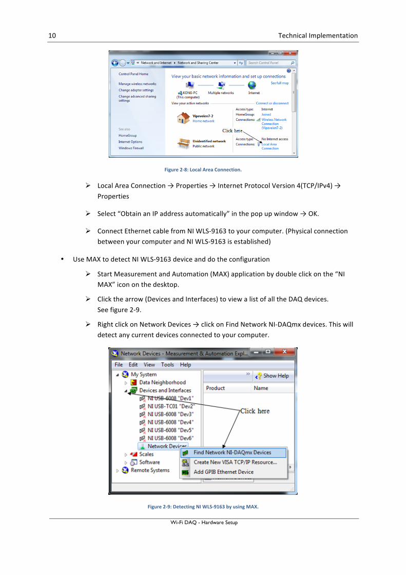
Figure 2-‐8: Local Area Connection.
Ø Local Area Connection → Properties → Internet Protocol Version 4(TCP/IPv4) → Properties
Ø Select “Obtain an IP address automatically” in the pop up window → OK.
Ø Connect Ethernet cable from NI WLS-‐9163 to your computer. (Physical connection between your computer and NI WLS-‐9163 is established)
• Use MAX to detect NI WLS-‐9163 device and do the configuration
Ø Start Measurement and Automation (MAX) application by double click on the “NI MAX” icon on the desktop.
Ø Click the arrow (Devices and Interfaces) to view a list of all the DAQ devices. See figure 2-‐9.
Ø Right click on Network Devices → click on Find Network NI-‐DAQmx devices. This will detect any current devices connected to your computer.
Figure 2-‐9: Detecting NI WLS-‐9163 by using MAX.
11 Technical Implementation
Wi-Fi DAQ - Hardware Setup
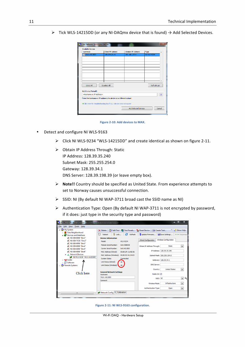
Ø Tick WLS-‐14215DD (or any NI-‐DAQmx device that is found) → Add Selected Devices.
Figure 2-‐10: Add devices to MAX.
• Detect and configure NI WLS-‐9163
Ø Click NI WLS-‐9234 “WLS-‐14215DD” and create identical as shown on figure 2-‐11.
Ø Obtain IP Address Through: Static IP Address: 128.39.35.240 Subnet Mask: 255.255.254.0 Gateway: 128.39.34.1 DNS Server: 128.39.198.39 (or leave empty box).
Ø Note!! Country should be specified as United State. From experience attempts to set to Norway causes unsuccessful connection.
Ø SSID: NI (By default NI WAP-‐3711 broad cast the SSID name as NI)
Ø Authentication Type: Open (By default NI WAP-‐3711 is not encrypted by password, if it does: just type in the security type and password)
Figure 2-‐11: NI WLS-‐9163 configuration.
12 Technical Implementation
Wi-Fi DAQ - Hardware Setup
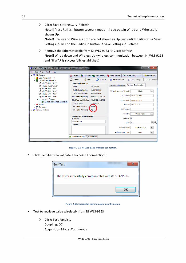
Ø Click: Save Settings... → Refresh Note!! Press Refresh button several times until you obtain Wired and Wireless is shown Up. Note!! If Wire and Wireless both are not shown as Up, just untick Radio On → Save Settings → Tick on the Radio On button → Save Settings → Refresh.
Ø Remove the Ethernet cable from NI WLS-‐9163 → Click: Refresh Note!! Wired down and Wireless Up (wireless communication between NI WLS-‐9163 and NI WAP is successfully established)
Figure 2-‐12: NI WLS-‐9163 wireless connection.
• Click: Self-‐Test (To validate a successful connection).
Figure 2-‐13: Successful communication confirmation.
• Test to retrieve value wirelessly from NI WLS-‐9163
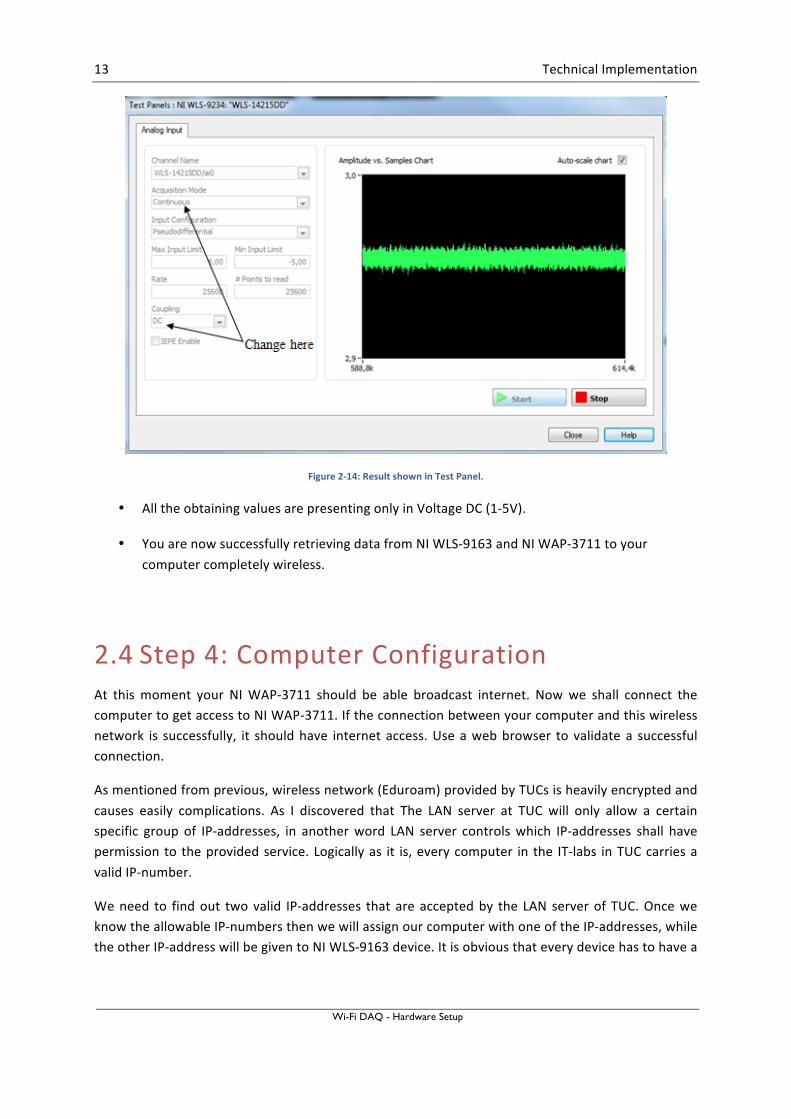
Ø Click: Test Panels… Coupling: DC Acquisition Mode: Continuous
13 Technical Implementation
Wi-Fi DAQ - Hardware Setup
Figure 2-‐14: Result shown in Test Panel.
• All the obtaining values are presenting only in Voltage DC (1-‐5V).
• You are now successfully retrieving data from NI WLS-‐9163 and NI WAP-‐3711 to your computer completely wireless.
2.4 Step 4: Computer Configuration At this moment your NI WAP-‐3711 should be able broadcast internet. Now we shall connect the computer to get access to NI WAP-‐3711. If the connection between your computer and this wireless network is successfully, it should have internet access. Use a web browser to validate a successful connection.
As mentioned from previous, wireless network (Eduroam) provided by TUCs is heavily encrypted and causes easily complications. As I discovered that The LAN server at TUC will only allow a certain specific group of IP-‐addresses, in another word LAN server controls which IP-‐addresses shall have permission to the provided service. Logically as it is, every computer in the IT-‐labs in TUC carries a valid IP-‐number.
We need to find out two valid IP-‐addresses that are accepted by the LAN server of TUC. Once we know the allowable IP-‐numbers then we will assign our computer with one of the IP-‐addresses, while the other IP-‐address will be given to NI WLS-‐9163 device. It is obvious that every device has to have a
14 Technical Implementation
Wi-Fi DAQ - Hardware Setup
valid IP-‐address that is accepted by the LAN server in able to utilize the resources broadcasting by the Wireless Access Point.
Note! The following IP-‐addresses are reserved (available) for the laboratory context.
IP-‐address: 128.39.35.239 128.39.35.240 128.39.35.241 128.39.35.226
Subnet mask: 255.255.254.0 Gateway: 128.39.34.1 DNS: 128.39.198.39
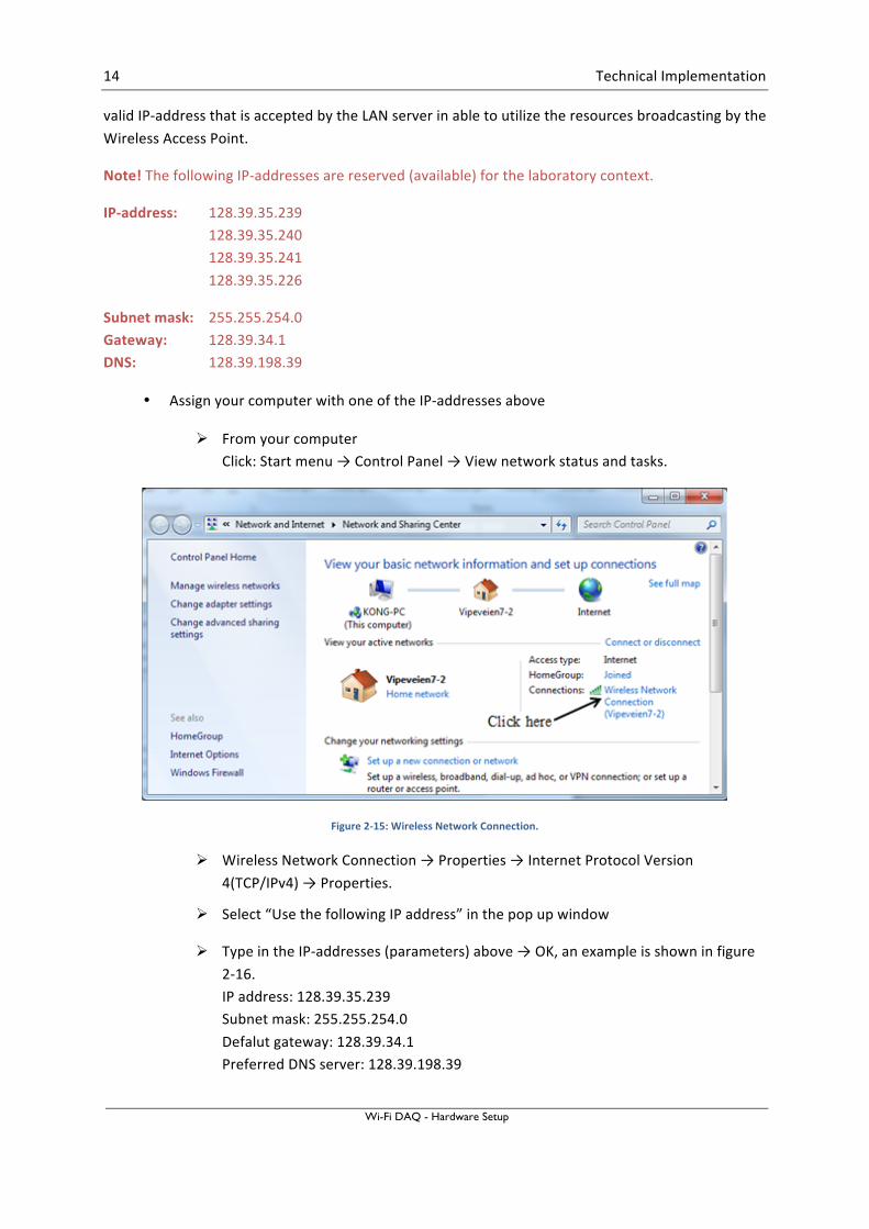
• Assign your computer with one of the IP-‐addresses above
Ø From your computer Click: Start menu → Control Panel → View network status and tasks.
Figure 2-‐15: Wireless Network Connection.
Ø Wireless Network Connection → Properties → Internet Protocol Version 4(TCP/IPv4) → Properties.
Ø Select “Use the following IP address” in the pop up window
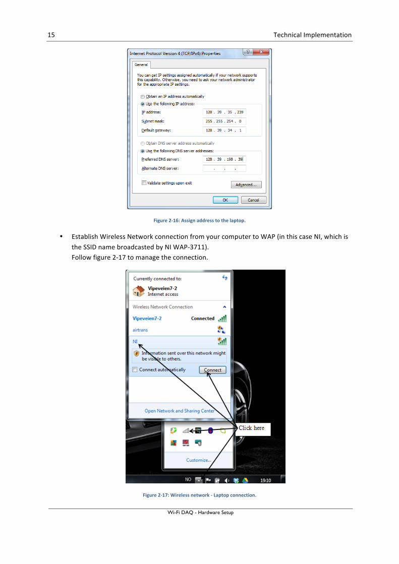
Ø Type in the IP-‐addresses (parameters) above → OK, an example is shown in figure 2-‐16. IP address: 128.39.35.239 Subnet mask: 255.255.254.0 Defalut gateway: 128.39.34.1 Preferred DNS server: 128.39.198.39
15 Technical Implementation
Wi-Fi DAQ - Hardware Setup
Figure 2-‐16: Assign address to the laptop.
• Establish Wireless Network connection from your computer to WAP (in this case NI, which is the SSID name broadcasted by NI WAP-‐3711). Follow figure 2-‐17 to manage the connection.
Figure 2-‐17: Wireless network -‐ Laptop connection.
16 Technical Implementation
Wi-Fi DAQ - Hardware Setup
Now your computer should be connected to NI WAP-‐3711. To validate the successful connection, use a web browser and surf to some home pages. Now your computer has access to internet from your own Wireless Access Point in TUC area, and not dependent on Eduroam.
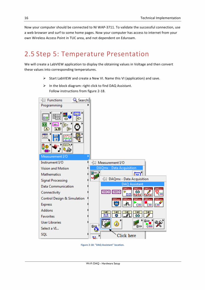
2.5 Step 5: Temperature Presentation We will create a LabVIEW application to display the obtaining values in Voltage and then convert these values into corresponding temperatures.
Ø Start LabVIEW and create a New VI. Name this VI (application) and save.
Ø In the block diagram: right click to find DAQ Assistant. Follow instructions from figure 2-‐18.
Figure 2-‐18: "DAQ Assistant" location.

17 Technical Implementation
Wi-Fi DAQ - Hardware Setup
• Configure the DAQ Assistant to obtain the Voltage values.
Ø Click: Acquire Signals → Analog Input → Voltage → ai0 (depending on which of the pin of NI 9234 were used) → Finnish.
Ø From pop up Window: Click Device → Change to DC → OK
Ø Make sure your Block Diagram looks like the one illustrated in figure 2-‐19. The value is presenting in the Front Panel.
Figure 2-‐19: LabVIEW application to retrieve data from DAQ.
Advance: The front panel shown in the previous figure present the value captured from the temperature sensor PT-‐100 in Voltage. The value needs to be converted into temperature [℃]. Try to improve the LabVIEW application that shows both in Voltage and degree Celsius as illustrated in figure 2-‐20.
Tips: Use silver style as layout.
Convert from Voltage to Temperature. Temperature [℃] = Voltage * a – b (define parameters a & b) 1 [V] = 0 [℃] 5 [V] = 50 [℃]
18 Technical Implementation
Wi-Fi DAQ - Hardware Setup
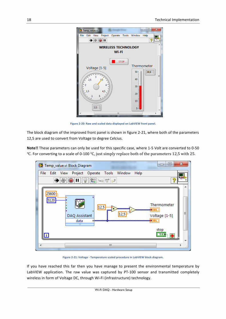
Figure 2-‐20: Raw and scaled data displayed on LabVIEW front panel.
The block diagram of the improved front panel is shown in figure 2-‐21, where both of the parameters 12,5 are used to convert from Voltage to degree Celcius.
Note!! These parameters can only be used for this specific case, where 1-‐5 Volt are converted to 0-‐50 ℃. For converting to a scale of 0-‐100 ℃, just simply replace both of the parameters 12,5 with 25.
Figure 2-‐21: Voltage -‐ Temperature scaled procedure in LabVIEW block diagram.
If you have reached this far then you have manage to present the environmental temperature by LabVIEW application. The raw value was captured by PT-‐100 sensor and transmitted completely wireless in form of Voltage DC, through Wi-‐Fi (infrastructure) technology.
19
3 Summary This chapter will summarize what have been done to get a successful wireless data transferring by utilizing Wi-‐Fi (infrastructure) technology, which is implemented on Windows 7 professional OS. The data transmission relies on National Instruments technology, where NI WAP-‐3711 will broadcast internet from TUCs LAN. Five different steps are required to present the raw data into temperature degree (℃).
Step 1: Setup and connect all the physical devices together.
Step 2: Configure NI WAP-‐3711
• In this particular case all we have to do is just simply establish connection between NI WAP-‐3711 and TUCs LAN with an Ethernet cable in between. By default NI WAP-‐3711 is correctly configured for this purpose.
Ø Power up NI WAP-‐3711 and push the reset button for at least five seconds. To make sure the device is configured as default.
Ø NI WAP should broadcast internet.
Step 3: Configure NI WLS-‐9163
NI WLS-‐9163 is used to transmit the temperature value to NI WAP-‐3711 and can be configured by using Measurement & Automation (MAX). MAX is a software which allows users to fully access and configure settings of NI WLS-‐9163.
• Download and install Measurement & Automation (MAX). http://joule.ni.com/nidu/cds/view/p/id/3423/lang/no
• Set Local Area Connection on your computer to obtain an IP address automatically.
• Connect Ethernet cable from NI WLS-‐9163 to your computer. (Physical connection between your computer and NI WLS-‐9163 is established)
• Use MAX to detect NI WLS-‐9163 device and do the configuration.
Ø Obtain IP Address Through: Static IP Address: 128.39.35.240 Subnet Mask: 255.255.254.0 Gateway: 128.39.34.1
Ø DNS Server: 128.39.198.39 (or no input require).
Ø Note!! Country should be specified as United State. From experience attempts to set to Norway causes unsuccessful connection.
Ø SSID: NI (By default NI WAP-‐3711 broad cast the SSID name as NI)
20 Summary
Wi-Fi DAQ - Hardware Setup
Ø Authentication Type: Open (By default NI WAP-‐3711 is not encrypted by password, if it does: just type in the security type and password)
Ø Click: Save Settings... → Refresh Note!! Press Refresh button several times until you obtain Wired and Wireless is shown Up. Note!! If Wire and Wireless both are not shown as Up, just untick Radio On → Save Settings → Tick on the Radio On button → Save Settings → Refresh.
Ø Remove the Ethernet cable from NI WLS-‐9163 → Click: Refresh Note!! Wired down and Wireless Up (wireless communication between NI WLS-‐9163 and NI WAP is successfully established)
• Click: Self-‐Test (To validate a successful connection).
• All the obtaining values are presenting only in Voltage DC (1-‐5V).
• You are now successfully retrieving data wirelessly from NI WLS-‐9163 and NI WAP-‐3711 to your computer completely wireless, in addition your NI WLS-‐9163 is broadcasting internet from TUC LAN.
Step 4: Configure computer
• At this moment your NI WAP-‐3711 should be able to broadcast internet.
• Now we shall connect the computer to get access to NI WAP-‐3711. If the connection between your computer and this wireless network is successfully, it should have internet access. Use a web browser to validate a successful connection.
• The LAN server at TUC will only allow a certain specific group of IP-‐addresses, in another word LAN server controls which IP-‐addresses shall have permission to the provided service. Logically as it is, every computer in the computer labs in TUC carries a valid IP-‐number.
• Find out two valid IP-‐addresses that are accepted by the LAN server of TUC. Once we know the allowable IP-‐numbers then we will assign our computer with one of the IP-‐addresses, while the other IP-‐address will be given to NI WLS-‐9163 device. It is obvious that every device has to have a valid IP-‐address that is accepted by the LAN server in able to utilize the resources broadcasting by the Wireless Access Point.
• The following IP-‐addresses are reserved (available) for the laboratory context. IP-‐address: 128.39.35.239 128.39.35.240 128.39.35.241 128.39.35.226

21 Summary
Wi-Fi DAQ - Hardware Setup
Subnet mask: 255.255.254.0 Default gateway: 128.39.34.1 Preferred DNS server: 128.39.198.39
• Assign your computer with one of the IP-‐addresses stated above. NOTE!! Since you already assigned 128.39.35.240 to NI WLS-‐9163, so you have to choose among the remaining addresses.
• Establish Wireless Network Connection from your computer to WAP (in this case NI, which is the SSID name broadcasted by NI WAP-‐3711).
• Now your computer should be connected to NI WAP-‐3711. To validate the successful connection, use a web browser and surf to some home pages. Now have access to internet from your own Wireless Access Point in TUC area, and not dependent on Eduroam.
Step 5: Temperature presentation on screen
• We created a LabVIEW application to display the obtaining values in Voltage and then convert these values into corresponding temperatures.
ü Start LabVIEW and create a New VI. Name this VI (application) and save.
ü In the block diagram: right click to find DAQ Assistant.
ü Configure the DAQ Assistant to obtain the Voltage values.
ü In the block diagram convert from Voltage to Temperature.
ü Focus on the layout in the front panel.
Congratulations!! As the final result you have managed to transmit data completely wirelessly by Wi-‐Fi (infrastructure) technology and by using National Instruments equipments.
Telemark University College
Faculty of Technology
Kjølnes Ring 56
N-‐3918 Porsgrunn, Norway
www.hit.no
Hans-‐Petter Halvorsen, M.Sc.
Telemark University College
Department of Electrical Engineering, Information Technology and Cybernetics
E-‐mail: [email protected]
Blog: http://home.hit.no/~hansha/
Room: B-‐237a