hoist to transfer athletes from wheelchair into a kayak
TRANSCRIPT

Hoist to Transfer Athletes from Wheelchair into a Kayak
Sponsors: Maggie Palchak, Disabled Sports Eastern Sierra Program
Coordinator
E.L. Smoogen, Disabled Sports Eastern Sierra
Dr. Brian Self, Cal Poly Mechanical Engineering Department
Team Advisors: Sarah Harding, Cal Poly Mechanical Engineering Department
Dr. Kevin Taylor, Cal Poly Kinesiology Department
Team Members: Jennifer Batryn
Javier Mendez
Kyle Mooney
June 7, 2013
Team Kayakity Quacks
California Polytechnic State University, San Luis Obispo
2
Statement of Disclaimer
Since this project is a result of a class assignment, it has been graded and accepted as fulfillment of the course requirements. Acceptance does not imply technical accuracy or reliability. Any use of information in this report is done at the risk of the user. These risks may include catastrophic failure of the device or infringement of patent or copyright laws. California Polytechnic State University at San Luis Obispo and its staff cannot be held liable for any use or misuse of the project.
Team Kayakity Quacks
California Polytechnic State University, San Luis Obispo
3
Table of Contents
1 - Introduction ............................................................................................................................... 7
2 - Background Research ................................................................................................................ 8
2.1 Kayak Design .................................................................................................................... 8
2.2 Existing Lifts ..................................................................................................................... 9
2.2.1 Pool lifts ......................................................................................................................... 9
2.2.2 Hospital lifts ................................................................................................................. 11
2.3.1 U-sling.......................................................................................................................... 11
2.3.2 Hygiene sling ............................................................................................................... 12
2.3.3 Fully body sling ........................................................................................................... 13
3 - Objectives ................................................................................................................................ 14
4 - Idea Generation........................................................................................................................ 16
5 – Design Ideation ....................................................................................................................... 17
5.1 The Over Head Crank ..................................................................................................... 17
5.2 The Chair ........................................................................................................................ 17
5.3 The DockSlide ................................................................................................................ 18
5.5 The Mover ....................................................................................................................... 19
5.6 The TrailLifter ................................................................................................................ 19
5.7 The Swiveler ................................................................................................................... 20
6 - Final Concept ........................................................................................................................... 21
6.1 Frame .................................................................................................................................. 21
6.2 Sling .................................................................................................................................... 22
6.3 Hoist Mechanism ................................................................................................................ 23
6.4 Legs ..................................................................................................................................... 24
6.5 Overhead Beam and Trolley ............................................................................................... 24
6.6 Overall Design .................................................................................................................... 25
6.7 Features ............................................................................................................................... 25
6.8 How to Operate ................................................................................................................... 26
6.9 Maintenance & Warnings ................................................................................................... 26
7 - Engineering Analysis ............................................................................................................... 28
7.1 Material Selection ............................................................................................................... 28
7.2 Testing Critical Points......................................................................................................... 28

Team Kayakity Quacks
California Polytechnic State University, San Luis Obispo
4
7.2.1 Overhead beam ............................................................................................................ 28
7.2.2 Legs .............................................................................................................................. 29
7.3 Finite Element Analysis (FEA) ........................................................................................... 29
7.3.1 I-Beam.......................................................................................................................... 29
8 - Management Plan .................................................................................................................... 31
9 - Manufacturing Plan ................................................................................................................. 32
9.1 Manufacturing Process........................................................................................................ 32
9.2 Outsourced and Purchased Components ............................................................................. 32
10 - Building of Hoist ................................................................................................................... 34
10.1 Legs ................................................................................................................................... 34
10.2 Connections....................................................................................................................... 35
10.3 I-Beam............................................................................................................................... 36
10.4 Feet .................................................................................................................................... 37
10.5 Purchased Components ..................................................................................................... 37
11 - Cost Analysis ......................................................................................................................... 39
12 – Testing................................................................................................................................... 40
12.1 Failure Modes and Effects Analysis ................................................................................. 40
12.2 Hardware Review.............................................................................................................. 40
12.3 Subjective Testing ............................................................................................................. 41
13 - Conclusion ............................................................................................................................. 43
Works Cited .................................................................................................................................. 44
Appendices .................................................................................................................................... 45
Appendix A: Quality Function Deployment (QFD) ................................................................. 46
Appendix B: Project Timeline .................................................................................................. 47
Appendix C: Engineering Analysis (Hand Calculations) ......................................................... 49
Appendix D: Drawings ............................................................................................................. 53
Appendix E: Failure Mode Effects Analysis (FMEA) ............................................................. 65
Appendix F: Hardware and Set-up Guide ................................................................................. 66

Team Kayakity Quacks
California Polytechnic State University, San Luis Obispo
5
List of Figures
Figure #
Page #
2-1 Recreational Kayak 8
2-2 Touring Kayak 8
2-3 Sit-on-Top Kayak - Single 8
2-4 Sit-on-Top Kayak - Tandem 9
2-5 Typical Pool Lit Designs 10
2-6 Manually Powered Hospital Lift 11
2-7 U-Sling Design 12
2-8 Hygiene Sling 12
2-9 Full Body Sling 13
5-1 Overhead Crank 17
5-2 The Chair 17
5-3 The DockSlide 18
5-4 The SideDock 18
5-5 The Mover 19
5-6 The TrailLifter 19
5-7 The Swiveler 20
6-1 Final design of the SideDock frame 22
6-2 Side view of the SideDock 22
6-3 U-Sling 23
6-4 Chain Hoist 23
6-5 Geared Trolley 24
6-6 Overall Design 25
7-1 Von Misses Stress on I-Beam 28
9-1 Manufacturing Flow Diagram 30
10-1 Legs in the Lathe 31
10-2 Legs in the Mill 32
10-3 Compound Miter Saw 33
10-4 Welding of Connection Pieces 33
10-5 Drilling Holes into the Overhead Beam 34
10-6 Feet Being Cut and Welded 34
10-7 Hanger With Cover and Bag 38
12-1 Hoist on Boat Ramp 41
12-2 Hoist on Beach 41
12-3 Testing with Adapted Kayaking Participant 42
13-1 Kayakity Quacks at Expo 43

Team Kayakity Quacks
California Polytechnic State University, San Luis Obispo
6
List of Tables Table # Page #
3-1 Kayak Hoist Engineering Specifications 13 6-1 Decision Matrix for Frame Design 19 6-2 Decision Matrix for Sling 21 6-3 Decision Matrix for Hoist Mechanism 22
11-1 Cost Analysis 33 12-1 Testing of Hardware 34 12-2 Subjective Testing 35

Team Kayakity Quacks
California Polytechnic State University, San Luis Obispo
7
1 - Introduction____________________________________________________________________________________
Disabled Sports Eastern Sierra (DSES), based in Mammoth Lakes, California, provides resources
and opportunities for athletes with disabilities so they can fully participate in a variety of
outdoors activities. The goal is to minimize the effects of the disabilities and give the
participants as much independence and freedom as possible. Tandem kayaking is one of the
events that takes place every spring and summer and one of the challenges that DSES faces is
transferring the athletes from their wheelchairs to the kayaks. Currently, several able-bodied
volunteers manually lift the athletes and place them in the kayaks, but this method is not ideal
for several reasons. Not only does it place a lot of stress on the people lifting, but more
importantly this method also takes away independence from the athletes. With funding from a
National Science Foundation grant, a new hoist has been designed to safely and easily transfer
the athletes from their wheelchair to a kayak with minimal assistance required. Our team, the
Kayakity Quacks, consists of California Polytechnic State University mechanical engineering
seniors Jennifer Batryn, Javier Mendez, and Kyle Mooney, with advisors Professor Sarah
Harding and Dr. Brian Self overseeing the project. DSES representatives E.L. Smoogen and
Maggie Palchak also served as a link to the end users of this project and aided in
communicating the needs and requirements of the organization. Team Kayakity Quacks has
researched the need, produced a design, and built a prototype which meets the criteria
specified. A complete report from the beginning designs to the manufacturing and testing of
the prototype hoist is being presented. The prototype has received very positive feedback from
athletes and volunteers alike. The prototype hoist will be put to use by the DSES athletes at
upcoming kayaking events for years to come.

Team Kayakity Quacks
California Polytechnic State University, San Luis Obispo
8
2 - Background Research__________________________________________________________________________
2.1 Kayak Design
Kayaks are split into several main categories, based on their design and intended use.
2.1.1 Recreational
Recreational kayaks are relatively wide and fairly stable. They have a large cockpit for
sit-inside designs making them easier to get into and out of but are not the best for
open water [1].
Figure 2-1. Recreational Kayak
http://www.neckykayaks.com/kayaks/recreation_kayaks/
2.1.2 Touring Touring kayaks are generally longer and more slender than recreational kayaks. The
cockpits are also smaller but they are better for open water and paddling for longer
durations. Touring kayaks are also more expensive [1].
Figure 2-2. Touring Kayak
http://www.neckykayaks.com/kayaks/touring/
2.1.3 Sit-on-Top Sit-on-top kayaks allow the easiest transfer in and out due to the open design and lack
of cockpit. They are generally wider, more stable and the person sits higher from the
water [1].
Figure 2-3. Sit on Top Kayak - Single
http://www.neckykayaks.com/kayaks/vector_series/
Team Kayakity Quacks
California Polytechnic State University, San Luis Obispo
9
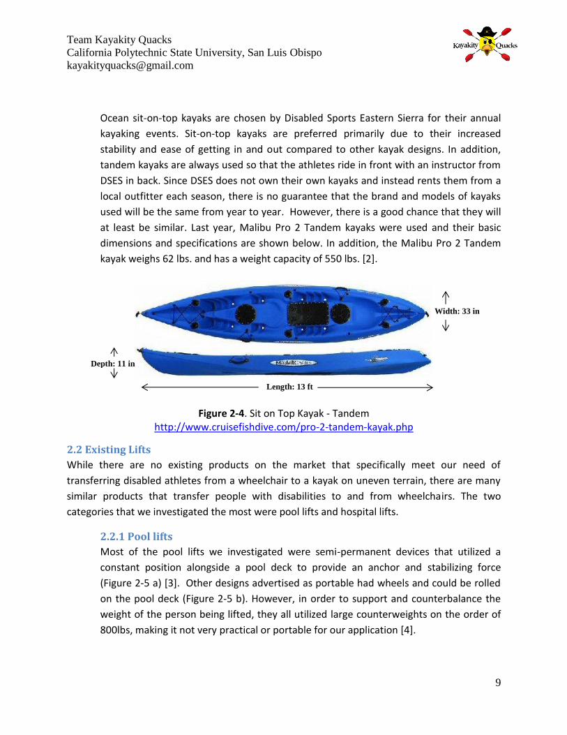
Ocean sit-on-top kayaks are chosen by Disabled Sports Eastern Sierra for their annual
kayaking events. Sit-on-top kayaks are preferred primarily due to their increased
stability and ease of getting in and out compared to other kayak designs. In addition,
tandem kayaks are always used so that the athletes ride in front with an instructor from
DSES in back. Since DSES does not own their own kayaks and instead rents them from a
local outfitter each season, there is no guarantee that the brand and models of kayaks
used will be the same from year to year. However, there is a good chance that they will
at least be similar. Last year, Malibu Pro 2 Tandem kayaks were used and their basic
dimensions and specifications are shown below. In addition, the Malibu Pro 2 Tandem
kayak weighs 62 lbs. and has a weight capacity of 550 lbs. [2].
Figure 2-4. Sit on Top Kayak - Tandem http://www.cruisefishdive.com/pro-2-tandem-kayak.php
2.2 Existing Lifts
While there are no existing products on the market that specifically meet our need of
transferring disabled athletes from a wheelchair to a kayak on uneven terrain, there are many
similar products that transfer people with disabilities to and from wheelchairs. The two
categories that we investigated the most were pool lifts and hospital lifts.
2.2.1 Pool lifts
Most of the pool lifts we investigated were semi-permanent devices that utilized a
constant position alongside a pool deck to provide an anchor and stabilizing force
(Figure 2-5 a) [3]. Other designs advertised as portable had wheels and could be rolled
on the pool deck (Figure 2-5 b). However, in order to support and counterbalance the
weight of the person being lifted, they all utilized large counterweights on the order of
800lbs, making it not very practical or portable for our application [4].
Length: 13 ft
Depth: 11 in
Width: 33 in

Team Kayakity Quacks
California Polytechnic State University, San Luis Obispo
10
http://www.mobilitytoys.com/images/catalog/category93.jpg
http://swimmingpoolhandicaplifts.com/wp-content/uploads/2011/11/pal-20-0000-lift-500.jpg
(a) (b)
Figure 2-5. Typical pool lift designs (a) semi-permanent design that anchors into pool
deck (b) Portable lift with counterweight
There were several main methods used to power the pool lifts [5].
o Manual/hydraulic
The manual powered lifts mainly utilized hydraulic pumps that an
assistant would pump in order to lift the person out of their wheel
chair. To get them into the pool, the overhead rod suspending them
would rotate and bring them over the pool, at which point the
assistant could lower them by again manually pumping. Most
manual lifts used a sling and included portable as well as permanent
models.
o Battery powered
Battery powered lifts were separated into models where the battery
controlled the lifting and rotation or just the lifting. The models
where only the lifting was battery operated required the assistance
of someone else to rotate the structure, whereas the other models
could be completely controlled by the user. Many of these models
also had waterproof remotes for easy and safe operation around the
water and utilized rigid seats.

Team Kayakity Quacks
California Polytechnic State University, San Luis Obispo
11
o Water powered
These devices used water pressure from a source such as a regular
garden hose or supply pipe. Water power is seen as a safe, cost
effective and environmentally friendly alternative to battery power.
These devices are generally permanently installed and most of them
used rigid seats.
2.2.2 Hospital lifts
The hospital lifts we investigated all had the same
basic design with variations in their lifting capacity and
power method. They are all designed to transport
patients from one resting surface to another (bed,
chair, commode, etc.) and are not meant as a
transport device. In addition, all of the hospital lifts
researched operated on the assumption that the
patient being lifted does not necessarily have physical
control over their bodies and thus does not aid at all in
the operation of the lift. Therefore, all lifts required
the help of least one other person to operate, with
some recommending the assistance of two others.
Lifting capacity varies based on specific models, but
standard lifts have a typical capacity ranging from 300-
450lbs. Other models are specially designed to transfer
larger patients up to 850lbs. Most lifts utilize slings (canvas, polyester, or nylon) to
interface with the patient and hold them when suspended in transit. The main methods
of powering the lifts included manual/hydraulics (Figure 2-6) and battery powered [6].
2.3 Existing Seats and Slings Many of the pool lifts researched utilized rigid seats to transport and interface with the person
being lifted. However, a larger number of devices used fabric slings, which are generally
cheaper and more adaptable to different people’s needs. There are three main types of slings
available on the market.
2.3.1 U-sling
One of the most commonly used sling designs is the U-sling. These come in a variety of
sizes and levels of support ranging from full back and neck support to just a support
across the mid back. They are fairly easy to get into and out of while in a sitting position.
http://www.1800wheelchair.com/siteimages/large/C-HLA-1.jpg
Figure 2-6. Basic manually
powered (hydraulic pump)
hospital lift design
Team Kayakity Quacks
California Polytechnic State University, San Luis Obispo
12
Figure 2-7. The U-Sling Design
http://www.rehabmart.com/imagesfromrd/DRV-13220S_head.jpg
http://www.alphamodalities.com/Products/Slings/Reusable/Universal_Sling_Series/AM-U_SeatSling/gallery/album/large/AM-U-SeatSling_ClipS.jpg
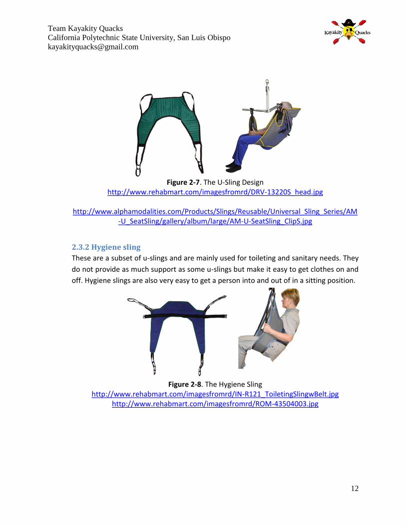
2.3.2 Hygiene sling
These are a subset of u-slings and are mainly used for toileting and sanitary needs. They
do not provide as much support as some u-slings but make it easy to get clothes on and
off. Hygiene slings are also very easy to get a person into and out of in a sitting position.
Figure 2-8. The Hygiene Sling
http://www.rehabmart.com/imagesfromrd/IN-R121_ToiletingSlingwBelt.jpg http://www.rehabmart.com/imagesfromrd/ROM-43504003.jpg

Team Kayakity Quacks
California Polytechnic State University, San Luis Obispo
13
2.3.3 Fully body sling
Full body slings provide the most support and are often used for amputees and others
that need the extra support. They are much more cumbersome to get into and out of
though since part of the sling actually goes under the person’s bottom, meaning that
they have to be either lifted or repositioned just to get the sling in place.
Figure 2-9. The Full Body Sling
http://www.rehabmart.com/imagesfromrd/IN-R110_FullBodySling_Mesh.jpg http://www.united-
rehab.net/monkeewrench//files/products/images/Full_Body_Sling_Plus.jpg

Team Kayakity Quacks
California Polytechnic State University, San Luis Obispo
14
3 - Objectives________________________________________________________________________________________
Team Kayakity Quacks will produce a hoist that will safely transfer the athletes from their
wheelchair to the kayak and vice-versa. There is currently no mechanism being used by
Disabled Sports Eastern Sierra to transfer the athletes between their wheelchairs and kayaks
except human power. After speaking with our sponsors, DSES representative Ms. Maggie
Palchak, E.L. Smoogen, and Dr. Brian Self, a set of requirements were agreed upon, which were
the basis for our design process.
The hoist will be transportable by one person and will have a minimal storage footprint.
The athlete will be able to be transferred with the help of only one other person.
No external power source will be used.
The hoist will be made to function along the shore, be it sand, rocks, or launch ramp. It
cannot be used to take off from a dock.
It will be made to at the least be partially waterproof.
The hoist will safely and comfortably lift a person of up to 250 pounds.
The cost to prototype will be less than the NSF grant given.
All requirements that were discussed were put into a Quality Function Deployment (QFD) and
plausible specifications for the hoist were then created. The QFD’s purpose is to identify and
meet the needs and desires of the customer. The QFD ultimately resulted in our engineering
specifications in Table 3-1.
Table 3-1. Kayak Hoist Engineering Specifications
Spec # Parameter Target Tolerance Risk Compliance
1 Weight 80 lb Max H A, I
2 Length (stored) 7 ft Max H A, I
3 Operator Force 30 lb +10/ -0 lbs M I, T, S
4 Range 36 in Min M A, S
5 Time (operation) 5 minutes Max M T, A, I
6 Time (assembly) 20 minutes + 10 / -0 M T, A, I
7 Weight Capacity 250 lbs Min L A, I
8 Cost 1500 $ Max L A
The targets of each parameter are plausible values for meeting the requirements desired by the
customer. A compliance section lists how each parameter will be met. The methods are
Analysis (A), Testing (T), Similarity to Existing Products (S), Inspection (I). There is a risk

Team Kayakity Quacks
California Polytechnic State University, San Luis Obispo
15
assessment which labels how difficult it will be to reach the aforementioned target of the
parameter. These levels of risk are High (H), Medium (M), and Low (L).
As shown in Table 3-1, our highest risk parameters are keeping the stored size small and weight
low. These targets will be difficult to meet, as similar lifts do not possess values anywhere close
in these parameters. Ms. Palchak expressed that the small storage footprint is of grave
importance. Therefore the team has decided that the time needed for assembly may be
sacrificed in order to maintain the dimensions of the stowed product at a minimum. The
capabilities of the athlete will determine how much assistance is needed. We will make sure
that at most only one assistant will be needed to move the athlete and launch them onto the
lake. A force of 30 lbs. by the operator is a plausible quantity, but if needed an absolute
maximum of 40 lbs. The time to operate will be considered from the time that the athlete is
strapped in to the time they are sitting on the kayak and vice-versa. The range is the distance
that the hoist will be able to move the athlete vertically. The target is to be able to manufacture
a working model with a total cost less than $1500.

Team Kayakity Quacks
California Polytechnic State University, San Luis Obispo
16
4 - Idea Generation_________________________________________________________________________________
Once the requirements and specifications were set and after our extensive background
research, we were ready to start brainstorming ideas. The first thing we did was break the hoist
down into the different components that would be necessary. Under each of these
components, we listed ideas for possible solutions. The components were broken down as
such:
• Power System
• Lifting Mechanism
• Frame
• Portability
• Stability
• Harness Configuration
After having a grasp on what would be needed, each team member created a separate sketch
of a possible hoist. Although these ideas were good plausible solutions, we knew we were still
not at an optimal design yet. Cal Poly has its own adaptive kayaking program and we were able
to take part in one of their events held at Morro Bay. It was very helpful to be involved in this
way and witness the transportation of the athletes first hand. We were also able to talk with
some of the athletes, their caretakers, and the volunteers at the event and get their input
regarding possible ideas and suggestions for improvement based on their experiences. We took
into account that this event was using a boat launch ramp, whereas DSES primarily does their
launches from a lake shore, but it was still a great experience and very helpful.
Our sponsor Maggie Palchak emphasized the importance of the storage size being small;
therefore we decided that the frame was the most important aspect of the project. We would
choose a frame design that meets the requirements, and design all other components based on
this frame. We also conferred with Dr. Self about our designs. In this meeting, he left it open to
our interpretation; however, he suggested a completely manually powered system. With no
battery or power source other than manual, it should consistently work for years with little to
no maintenance. The following are our top seven designs.

Team Kayakity Quacks
California Polytechnic State University, San Luis Obispo
17
5 – Design Ideation________________________________________________________________________________
5.1 The Over Head Crank
The design shown in Figure 5-1 is based off of the lifts commonly seen in hospitals. The athlete
would wheel their chair next to the kayak and a pulley or hydraulic system will lift them out of
the wheelchair. Hospital lifts are able to have supports go under the bed to which the patient is
being transferred which provides the stabilization when moving the center of mass away from
the central frame; however our product will not be able to do this due to the kayak resting on
the ground. The supports in this design will instead go over the kayak in order to prevent the
entire structure from tipping over during the transfer of the athlete.
Pros
Would allow the athlete to perform most duties in the
transfer
Cons
Bulky and difficult to move.
Kayak and athlete move to hoist instead of hoist moving to
athlete and kayak.
The supports would interfere with the launching of the kayak.
5.2 The Chair
The concept of the chair (seen below in Figure 5-2) came from the need of helping the athletes
get through the terrain to the water. The athlete would sit in this new wheelchair that would
make it easier on the athlete as well as the volunteers to move the athletes across the beach.
The Chair will be wide enough to roll over the kayak and a special release mechanism would
allow the athlete to lower themselves into the front seat of the kayak.
Pros
Make it easier to move across the beach and
transfer to the kayak independently
Cons
The Chairs increased width (to fit around the
kayak) might make it hard to wheel.
Would still need a way to transfer from own
wheelchair to the Chair.
Figure 5-1. OverHead Crank
Figure 5-2. The Chair
Team Kayakity Quacks
California Polytechnic State University, San Luis Obispo
18
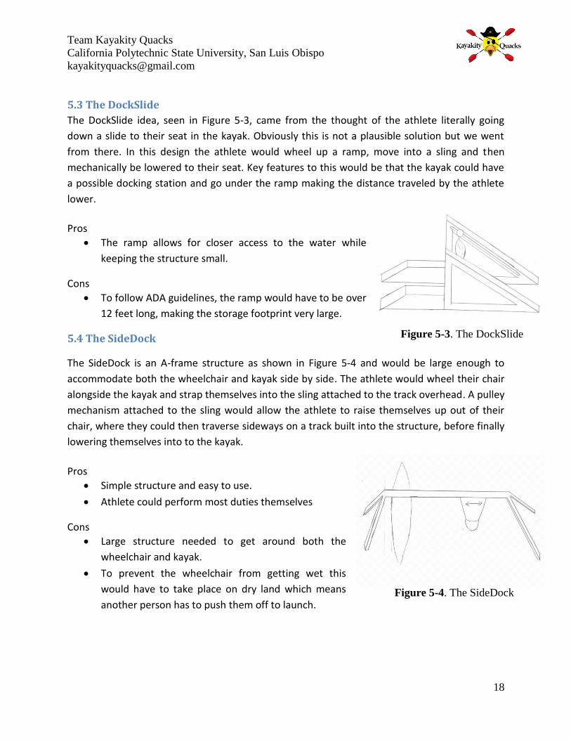
5.3 The DockSlide
The DockSlide idea, seen in Figure 5-3, came from the thought of the athlete literally going
down a slide to their seat in the kayak. Obviously this is not a plausible solution but we went
from there. In this design the athlete would wheel up a ramp, move into a sling and then
mechanically be lowered to their seat. Key features to this would be that the kayak could have
a possible docking station and go under the ramp making the distance traveled by the athlete
lower.
Pros
The ramp allows for closer access to the water while
keeping the structure small.
Cons
To follow ADA guidelines, the ramp would have to be over
12 feet long, making the storage footprint very large.
5.4 The SideDock
The SideDock is an A-frame structure as shown in Figure 5-4 and would be large enough to
accommodate both the wheelchair and kayak side by side. The athlete would wheel their chair
alongside the kayak and strap themselves into the sling attached to the track overhead. A pulley
mechanism attached to the sling would allow the athlete to raise themselves up out of their
chair, where they could then traverse sideways on a track built into the structure, before finally
lowering themselves into to the kayak.
Pros
Simple structure and easy to use.
Athlete could perform most duties themselves
Cons
Large structure needed to get around both the
wheelchair and kayak.
To prevent the wheelchair from getting wet this
would have to take place on dry land which means
another person has to push them off to launch.
Figure 5-3. The DockSlide
Figure 5-4. The SideDock

Team Kayakity Quacks
California Polytechnic State University, San Luis Obispo
19
5.5 The Mover
In this concept the four legged structure surrounds the athlete. From an overhanging sling and
pulley system, the athlete is lifted out of the chair. Another person from behind the structure
must push the structure to the water and over the kayak. The athlete can then lower
themselves down and launch on to the lake.
Pros
Will be portable and lightweight
Allows for access close or even in the water
Cons
Another person is required to transport the structure
while the person is suspended in the air
5.6 The TrailLifter
The TrailLifter would allow ease of transport for the athlete as well as the kayak. The kayak will
be loaded onto a trailer in the parking lot or a loading zone. The athlete will then be hoisted
into the kayak from a lift that is attached to the trailer. Once in the kayak, another volunteer
will push the trailer into the water and launch the kayak onto the lake.
Pros
Easy transfer of athlete and kayak across the terrain to the
water
Cons
The organization would prefer to not have to take the kayak
out of the water every time they switch athletes.
Figure 5-5. The Mover
Figure 5-6. The TrailLifter

Team Kayakity Quacks
California Polytechnic State University, San Luis Obispo
20
5.7 The Swiveler
In this design the athlete will be lifted in the air from an overhead hanger. A crank will be
placed on the main base allowing the athlete to operate it themselves. The crank will cause the
entire structure to turn on a pivot point, and after rotating 180 degrees the athlete will be
directly above the kayak and capable of lowering themselves down.
Pros
Allows for independent use by the athlete and close
water access.
Cons
To make it around the back edge the structure will have
to be very large. Also, it would be difficult to turn through
rough terrain.
Figure 5-7. The Swiveler

Team Kayakity Quacks
California Polytechnic State University, San Luis Obispo
21
6 - Final Concept____________________________________________________________________________________
6.1 Frame
A decision matrix was created of the three best and most plausible ideas. These three were The Mover, The TrailLifter, and the SideDock. In this decision matrix we assigned a point value to each parameter based on their importance. The results are found in the following table.
Table 6-1. Decision Matrix for Frame Design
Weight The Mover The TrailLifter
The SideDock
Portability 3 - -3 - -3 - -3
Safety 5 + 5 + 5 ++ 10
Lightweight 3 - -3 -- -6 - -3
Easy to Assemble 2 - -2 - -2 - -2
Easy to Operate 4 + 4 + 4 + 4
Cost 2 - -2 - -2 - -2
Manufacturability 1 - -1 - -1 - -1
Operate in Rough Terrain
4 + 4 + 4 + 4
Level of Independence 4 + 4 + 4 ++ 8
Strain on Operator 5 ++ 10 + 5 + 5
Total 16 8 20
According to our study we found that the Mover and the SideDock were the best options. Ms.
Palchak informed us that the TrailLifter did not meet the needs of DSES and was therefore not a
design to pursue further. Deciding between the other two was a difficult decision. The team
originally thought that the Mover was the best option and we selected it for our original
concept review. It would allow for a very minimal amount of strain by the volunteer and would
break down and store nicely. The SideDock on the other hand would have to be much larger to
accommodate both the wheelchair and kayak under its structure. In addition, the kayak would
not be ready to launch as it would have to be mostly up on shore. The SideDock allows the
athlete to perform most of the transfer duties themselves if they have the upper body strength,
giving it a high level of independence for the athletes. After consulting with E.L. Smoogen at the
beginning of winter quarter, it was agreed that the process of being transported while
suspended from the Mover may be scary for some of the athletes. There is also a possibility of
tipping over on the rough terrain, so the SideDock, which remains stationary and minimizes the
in-air transfer distance, was ultimately chosen as the best design.

Team Kayakity Quacks
California Polytechnic State University, San Luis Obispo
22
Figure 6-1. Final design of the SideDock frame
Figure 6-2. Side view of the SideDock showing
adjustable leg heights for uneven terrain
6.2 Sling
Hospital lifts come with a full body sling, which is very secure; however the athlete would need
to be completely lifted in order to get the sling under his/her buttocks. Our team tried to create
mock-up designs of different types of slings that would safely secure the athlete but prevent
having to lift them in the first place. We created a rigid body frame with L-shaped bars that
would have two main pieces of fabric. The first would go behind the back of the athlete with

Team Kayakity Quacks
California Polytechnic State University, San Luis Obispo
23
the rigid bars on both sides. The athlete would then take the
second strip of fabric and slide it under his/hers legs and attach it
to the rigid frame. Then, cables to lift the athlete would be
attached to the rigid bars and would lift the athlete like they are
sitting in a chair. This design worked and was easier than the full
body sling but had added unnecessary weight and complexity. Also
it may not have worked for athletes with above knee amputations.
We also created a U-sling. This sling slides down the back then
wraps under the thighs of the athlete. This type of sling is widely
used and is the best solution for the kayak hoist.
Table 6-2. Decision Matrix for Sling
Weight U sling Weighted Score
Rigid frame sling
Weighted score
Full body sling
Weighted score
Comfort 3 + 3 + 3 + 3
Safety 5 + 5 + 5 + 5
Ease of use 1 + 1 + 1 0
Cost 2 - -2 -- -4 - -2
Withstand outdoor environment
3 0 - -3 0
Level of independence
4 ++ 8 ++ 8 + 4
Strain on operator
4 + 4 + 4 + 4
Total 19 14 14
6.3 Hoist Mechanism
The Hoyer lift uses a hydraulic system which pumps the hoist up and down.
This option was considered however it makes it harder to allow the athlete
to operate themselves and was not as easy to incorporate into our frame
design. Still wanting everything to be manually powered, we looked into
using a pulley system. A multi-pulley system would need numerous pulleys to
have a reasonable force-to-lift ratio. We then discovered a differential pulley
or a chain hoist system. These systems offer an excellent mechanical
advantage with only two pulleys. The mechanism is also self-locking which is
Figure 6-3. U-sling
Figure 6-4.Chain hoist

Team Kayakity Quacks
California Polytechnic State University, San Luis Obispo
24
a necessary safety feature. The only downside is that to get the mechanical advantage, a very
long chain pull is required to lift but it does come at a very low application force. Retail prices
on existing chain hoists start at around $80, making them very affordable for our project
budget.
Table 6-3. Decision Matrix for Hoist Mechanism
Weight Chain hoist
Weighted score
Pulley system
Weighted score
Hydraulics Weighted score
Safety 5 + 5 + 5 + 5
Durability 3 0 - -3 0
Cost 1 -- -2 - -1 -- -2
Withstand outdoor environment
2 - -2 - -1 0
Level of independence
4 ++ 8 + 4 + 4
Strain on operator
4 ++ 8 + 4 + 4
Operation time
1 - -1 0 + 1
16 8 12
6.4 Legs
The legs will be in the shape of an upside down “V”. This will give the entire structure stability
with each leg angled at 30° from the vertical. The legs are connected to the beam by custom
made pieces that will be designed to fit each leg. These connections will permit each leg to be
adjustable allowing the height to change up to an angle of 15 degrees. This will ensure that the
structure can be level on any surface. The bottom of each leg will feature a small foot. This foot
will be covered in rubber and will give traction to the structure in the case that it is put on
cement or gravel surface.
6.5 Overhead Beam and Trolley
An Aluminum I-beam works well for our design. The I-beam is
lightweight; however, has a large moment of inertia. This will allow
us to put a high force and moment on this beam. I-beams are not
good for torsion but we do not need to worry about that with our
current design. Many existing trolley systems run along an I-beam.
Figure 6-5. I-beam trolley

Team Kayakity Quacks
California Polytechnic State University, San Luis Obispo
25
This allowed us to buy a trolley that is specified to carry and move the load needed. To easily
move from side to side along the I-beam, the team has decided to purchase a trolley with chain
and gear mechanism. This additional chain will allow the athlete to move themselves in the
horizontal direction.
6.6 Overall Design
Fig 6-6: SideDock design with major components
6.7 Features
Some major design features of the SideDock include:
Lock washers and wing nuts on the connection for quick assembly without the need for
tools
Pin connections on legs with six holes in each leg for individual height adjustment. Can
account for up to 15° angled surface or uneven terrain.
Feet swivel to adjust for inclined surfaces
Rubberized bottoms on feet for increased traction
Geared trolley with chain for easy and independent lateral movement
Chain hoist for easy and independent vertical movement (less than 10 pounds of pulling
force necessary to lift 250 pound person)

Team Kayakity Quacks
California Polytechnic State University, San Luis Obispo
26
U-sling allows for easy transfer into and out of the sling. Provides full support without
having to move athlete from sitting position
6.8 How to Operate
The entire structure will be placed near the water with the kayak inside the legs and against
one of the sides. There will be enough room for the athlete to then wheel up alongside the
kayak. The sling will be connected to a hanger, or support bar, which in turn is attached to the
hoist mechanism. After securing themselves in the sling, the athlete will be able to lift
themselves out of their chair using the chain hoist. Once securely lifted in the sling, an assistant
will pull the wheelchair away. The trolley is geared and has an additional chain that the athlete
can use to move themselves laterally across the overhead beam. Once above the kayak, the
athlete will lower themselves to the seat, again using the chain hoist. The athlete then unhooks
from the sling and they are ready to launch.
6.9 Maintenance & Warnings
The hoist was designed and manufactured to safely move an athlete of up to 400 lbs. However,
some maintenance and safety precautions must still be exercised to ensure the safety of the
athletes. The following table lists all the maintenance the hoist must receive in order to prevent
any failures.
Table 6-4. Kayak Hoist Maintenance List
Maintenance Description Frequency
Check chain links and ensure there are no knots
Unwind any chain knots that might have resulted from transportation or set-up.
Before Each Use
Check Feet Connections Ensure the bolts are tightly
fastened. If not, use a wrench to tighten.
Before Each Set-Up
Clean sand residue Wipe down the whole
structure and get rid of any sand residue.
After Taking it Apart
Team Kayakity Quacks
California Polytechnic State University, San Luis Obispo
27
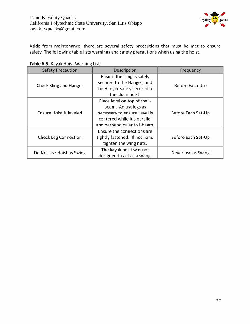
Aside from maintenance, there are several safety precautions that must be met to ensure safety. The following table lists warnings and safety precautions when using the hoist.
Table 6-5. Kayak Hoist Warning List
Safety Precaution Description Frequency
Check Sling and Hanger
Ensure the sling is safely secured to the Hanger, and
the Hanger safely secured to the chain hoist.
Before Each Use
Ensure Hoist is leveled
Place level on top of the I-beam. Adjust legs as
necessary to ensure Level is centered while it’s parallel
and perpendicular to I-beam.
Before Each Set-Up
Check Leg Connection Ensure the connections are
tightly fastened. If not hand tighten the wing nuts.
Before Each Set-Up
Do Not use Hoist as Swing The kayak hoist was not
designed to act as a swing. Never use as Swing

Team Kayakity Quacks
California Polytechnic State University, San Luis Obispo
28
7 - Engineering Analysis___________________________________________________________________________
The goal is to make the product as small, portable, and lightweight as possible. However we
cannot risk safety in order to achieve these goals. Assumptions were made in order to calculate
the necessary beam widths.
1. Assume the force is at the center point of the top frame. Therefore producing an even
distribution between the two legs.
2. The force is the weight of the maximum person with a specified factor of safety.
3. In Buckling assume a pin to pin joint for maximum safety.
With these assumptions we can calculate the necessary beam thickness and width to safely
support and transfer the maximum load with a specified material.
7.1 Material Selection
In order to make the appropriate engineering analysis, a material had to be selected for the
structure. The main criteria we were searching for are as follows:
Lightweight
Strong
Corrosion Resistant
Low Cost
We found that Aluminum Alloy 6061would be an appropriate material selection. It is strong
with a yield strength of 40ksi and ultimate strength of 45ksi. It is relatively lightweight with a
density of .0975 lb/in3. Aluminum is corrosion resistant and will not rust therefore it can go in
and out of the water. Aluminum Alloy 6061 is often used in construction of yachts and SCUBA
tanks.
7.2 Testing Critical Points
The critical points are where the greatest forces and moments occur within the structure. We
had to size each component of our frame to safely endure these stresses. Hand calculations
were done to find the minimum width of the legs and the overhead beam and can be found in
Appendix C.
7.2.1 Overhead beam
The critical point of the overhead beam is the center point. We know this point will have the
greatest deflection as well as the largest bending moment. We selected an I-beam and size and
then did the testing calculations. To solve for the maximum deflection, superposition was used.
The maximum moment that is created must be less than the yield strength of the material of
the beam. The beam sized 3” x 2.5” x .15” is sufficient to hold the load.

Team Kayakity Quacks
California Polytechnic State University, San Luis Obispo
29
7.2.2 Legs
The legs must withstand the moment that will be created by the person hanging, as well as not
buckling from the force. In this exercise the goal was to find the minimum diameter that could
support these loads. We wanted to stay very conservative because it is crucial that the legs
never fail. The structure does not really act as a pin to pin column; however, this was chosen in
order to have a larger effective length factor (K). With this criteria the minimum diameter
needed to prevent buckling, with a thickness of .125 in, is 1.5 inches. The load in which one leg
will feel is exaggerated in each case. The maximum moment that we applied to the leg is
14400in-lb. The minimum diameter to withstand this, with the same thickness, is 1.98in. A leg
diameter of 2.5 in. was chosen to safely satisfy this requirement. These calculations can be
found in Appendix C. Finite element analysis was also performed to ensure that the hand
calculations were accurate results.
7.3 Finite Element Analysis (FEA)
Finite Element Models were used to investigate the stresses observed by the top beam of our
design. Since we were only considering the top beam, the rest of the structure was not
modeled. Instead, the joint between the top beam and legs was modeled as a pin-fixed
connection. Lastly, all models were validated with hand calculations to verify the accuracy of
the FEA model.
7.3.1 I-Beam
I-beams are typically used in factory settings along with trolley systems. To determine whether
it would be a good option for our design, a finite element model was created. A load of 500
pounds was placed in the middle of the beam to simulate the critical loading. The beam was
modeled with a 2-D beam element. Symmetry was used to reduce computation time, and
increase accuracy. Section properties given were those of 6061 T6 Aluminum 3”x2.5”x0.15” I-
beam.

Team Kayakity Quacks
California Polytechnic State University, San Luis Obispo
30
Figure 7-1. Von mises stress on I-beam at its critical point. Image shows half of the beam since a symmetrical constraint was used. Max stress is approximately 14.5 Ksi.
Results of the analysis showed that the maximum stress would be 14.5 Ksi. This value is far
below the yield strength of aluminum, which is 40 ksi. This gives a final safety factor of 2.7.
These results prove that the I-beam is a good and safe design.

Team Kayakity Quacks
California Polytechnic State University, San Luis Obispo
31
8 - Management Plan______________________________________________________________________________
The following is a breakdown of roles delegated to each member of our team. Although only a
limited amount of roles overlap between team members, it is everyone’s responsibility to
uphold their engineering ethics with their own roles and other team member’s roles. That
includes completing their assigned tasks to the best of their ability before each deadline, and
occasionally reviewing other member’s tasks.
Team Member Roles
Jennifer Batryn Information Gathering, Engineering Analysis, Prototype Fabrication, Testing Plans
Javier Mendez Information Gathering, Engineering Analysis, Documentation of Project Progress, Prototype Testing
Kyle Mooney Information Gathering, Engineering Analysis , Manufacturing Considerations, Prototype Testing

Team Kayakity Quacks
California Polytechnic State University, San Luis Obispo
32
9 - Manufacturing Plan_________________________________________________________
The Side Dock consists of components which will be outsourced and a few that will be self-
manufactured. Having our main components outsourced, such as the trolley and chain hoist,
will reduce our manufacturing time. In addition, outsourcing our main components from a
reputable source will add credibility to our product since these products have already
undergone extensive engineering analysis from their respective vendor. At the same time, we
still have to manufacture some components giving us hands-on experience and staying true to
Cal Poly’s “Learn by Doing” motto.
9.1 Manufacturing Process
Figure 9-1. Manufacturing flow diagram showing simultaneous fabrication.
9.2 Outsourced and Purchased Components
The major components that will be outsourced are the trolley system, chain hoist, and the sling.
Trolley system and chain host applications are common in industrial settings where heavy loads

Team Kayakity Quacks
California Polytechnic State University, San Luis Obispo
33
are transported. Mostly all products have a load capacity of 1 ton; however since we are
dealing with much lower loads we will buy a product with a load capacity of ½ ton. Selecting
this product will reduce the weight of the trolley while keeping a very reasonable safety factor
in our product. The sling is often found in hospitals today. They come in different sizes based on
the size of the person. We have chosen a size that is rated to fit the maximum weight of 250
lbs. The smaller people will still be able to fit in this because it is adjustable on the hanger.

Team Kayakity Quacks
California Polytechnic State University, San Luis Obispo
34
10 - Building of Hoist_______________________________________________________________________________
The manufacturing was broken into segments. Many of the sections could be built
simultaneously, therefore giving us options on what and when to work. The following will show
and describe each component and its fabrication.
10.1 Legs
The pipes purchased for the legs had a 2 ½ inch outer diameter. They were designed to
telescope in the connection pipes, which had a 2 ½ inch inner diameter. However, due to the
tolerances for each pipe dimension, there was some interference initially. In order to obtain a
proper fit, it was decided that the legs should be machined down. Due to the 8 foot length, the
legs were too big to fit on the lathes in the mechanical engineering shop, so they were taken to
the bio resource and agricultural engineering shop. The pipes were not perfectly true or straight
due to standard manufacturing of them and several passes were made on the lathe to make
them more true and get the diameter down to a more acceptable level for telescoping.
Fig 10-1: The legs in the lathe
Once the legs were machined to easily slide in and out of the connections pieces, they were
taken to a mill to drill a series of holes for the pin connections. The mill helped ensure that the
holes were all aligned with respect to one another and went through the center of the pipe.
After the pin holes were made, a hole for the feet was also made.

Team Kayakity Quacks
California Polytechnic State University, San Luis Obispo
35
Fig 10-2: Legs in the mill
10.2 Connections
The connection pieces were the most intricate part of the manufacturing process. The tubes
needed to be cut to create a 60 degree angle, but because it needed to be welded along a flat
plate another angle cut was needed to make the tube flat. To add stability to our hoist we
needed to splay the connections outward at a minimum of 5 degrees. This small angle was
accomplished by using a compound miter saw. Holes on the uncut end were drilled to fit the
pins in order to secure the leg’s height.
Fig 10-3: Compound Miter Saw

Team Kayakity Quacks
California Polytechnic State University, San Luis Obispo
36
For the top part of the connection, a ¼” flat plate was cut to fit on the I-beam, as well as have
enough room for the welder to weld the tubes to the plate. Holes were drilled in these plates to
fit a bolt through for a spot to attach to the I-beam. The strength of the welds is a critical part of
our design and TIG welding aluminum is hard to do well without a lot of experience, so we hired
a student shop tech to do the welding for the connections.
Fig 10-4: Welding of Connection Pieces
10.3 I-Beam
The I-beam was cut down to fit the maximum storage length of 7 ft. This length still left plenty
of room for the wheelchair and kayak to fit underneath the device. Holes were then drilled to
attach the connections to the I-beam. The ¼” bolts can be attached without any tools. This is
accomplished with lock washers and wing nuts.
Fig 10-5: Drilling Holes into the overhead beam

Team Kayakity Quacks
California Polytechnic State University, San Luis Obispo
37
10.4 Feet
The feet were designed similar to those of an extension ladder. They were designed to allow
one degree of freedom and a full range of motion along one axis. This ensures that the feet
remain flat on any angle of surface. A ¼” aluminum sheet metal was used to create these. The
trapezoidal shape was done to prevent sharp corners and to be aesthetically pleasing. A rig with
the same size legs was created to create an easy environment for our welder. The rig ensured
that the trapezoidal wall of the feet were perpendicular with the bottom plate of the feet and
parallel with the legs.
Fig 10-6: Feet Being Cut and Welded
10.5 Purchased Components
The components that were outsourced worked perfectly. We did however notice opportunity
to optimize some of these components to better fit our application. The chains on the geared
trolley were much too long. Knowing that the person would only be moving side to side after
they are at their highest point, we decided to resize the chain to a height that was not bumping
into the person, but still long enough to easily be reached. There are two chains on the chain
hoist. The black chain lifts the person up and down, whiles the silver chain loops through the
hoist and is what the person pulls. The range of the black chain was for 10 ft. As the maximum
height of our hoist is not this tall, we cut the chain shorter. The silver chain was also cut;
however, because the entire hoist is adjustable we realized that this chain still needed to have a
very large range. The excess chain was always in the lap of the athlete and this could cause
some discomfort. To prevent this, a cover for the hanger was created. This cover comes
attached with a bag which will hold the excess chain as the athlete pulls themselves up and
down.

Team Kayakity Quacks
California Polytechnic State University, San Luis Obispo
38
Fig 10-7: Hanger with Cover and Bag

Team Kayakity Quacks
California Polytechnic State University, San Luis Obispo
39
11 - Cost Analysis___________________________________________________________________________________
The team was given $1,500 from a grant by the National Science Foundation (NSF) to buy all
components needed to manufacture a working hoist. Table 11-1 shows the following price of all
materials which were purchased as well as any outside labor costs. Pieces that are labeled as no
cost were graciously donated to our team.
Table 11-1: Cost Analysis
Part Item Part # Quantity Price ($)
Overhead Beam I-beam 100 1 98.04
Level 101 1 6.67
Connection Tubes 200 4 106.04
Bolts 201 8
6.57 Lock Washers 202 8
Wing Nuts 203 8
Legs Poles 300 4 243.80
Pins 301 4 19.61
Feet Bolts 400 4
10.07 Washers 401 8
Nuts 402 4
Rubber 403 1 0.00
Sheet Metal 404 1 0.00
Chain Hoist Hoist 500 1 94.51
Chain Links 501 2 3.77
Trolley Geared Trolley 600 1 151.19
Sling Attachment Hanger 700 1 25.57
Cover 701 1 25.00
Sling Sling 800 1 82.99
Labor and Misc. Welding
4 hr. 64.00
Powder Coating
1 120.00
Duffle Bag 1 21.59
Total $1079.42

Team Kayakity Quacks
California Polytechnic State University, San Luis Obispo
40
12 – Testing__________________________________________________________________________________________
12.1 Failure Modes and Effects Analysis
To verify that we are satisfying all the specifications we made a failure modes and effects
analysis (FMEA) The FMEA is used as a way to identify all the ways in which the hoist may fail.
The FMEA lists each component and the different functions that could fail. Then each
component is looked at how specifically it could fail. Each potential failure is ranked on a
severity scale of 1-10 (with 10 causing death or serious injury to the athlete). The FMEA can be
found in Appendix E.
12.2 Hardware Review
Two types of tests were conducted with our built product. The type was a review on the hardware of the final prototype. These are hard values which were measured or tested.
Table 12-1: Testing of Hardware
Spec. # Parameter Target Tolerance Test Result
1 Weight 80 lbs. Max 73 lbs. Pass
2 Length 7 ft. Max 7 ft. Pass
3 Operator Force 30 lbs. Max <10 lbs. Pass
4 Vertical Range 36 in. Min. 54 in. Pass
5 Operation Time 5 minutes Max 3 minutes Pass
6 Assembly Time 20 minutes -0/+10 8 minutes Pass
7 Weight Capacity
250 lbs. Min 400 lbs. Pass
8 Cost $1500 Max Pass
In regards to the time to assemble, a fellow student was shown how to set up the entire hoist
by a member of the Kayakity Quacks team. She was then timed in putting it back together. This
was also the time to build with the connection pieces unattached to the overhead beam. In
most cases we recommend keeping these attached. It will also cut off a few minutes from the
assembly time. In regards to the time to operate, we timed a student from the moment that
the sling was under their body and connected to the hanger. Time was then taken from the
moment the athlete started to pull them up, until they moved themselves over and touched
down on the kayak. The hoist was also taken to different locations to show that it could be
stable on different terrains.

Team Kayakity Quacks
California Polytechnic State University, San Luis Obispo
41
Fig 12-1: Hoist on Boat Ramp
Fig 12-2: Hoist on Beach
12.3 Subjective Testing
Subjective testing was accomplished through the help of a participant and a volunteer of the
Cal Poly Adaptive Kayaking program. These tests are based on their judgment and compared to
the previous method as well as other existing similar products.

Team Kayakity Quacks
California Polytechnic State University, San Luis Obispo
42
Table 12-2: Subjective Testing
Parameter Test
Comfort Approved
Ease of Use (Athlete) Approved
Ease of Use (Volunteer) Approved
Level of Independence Approved
Fig 12-3: Testing with Adapted Kayaking participant John Lee

Team Kayakity Quacks
California Polytechnic State University, San Luis Obispo
43
13 - Conclusion______________________________________________________________________________________
The goal of this project was to produce a hoist that will safely transfer athletes from their
wheelchair to the kayak and vice-versa. With this goal in our mind we designed and
manufactured a light weight, easy to operate, and collapsible hoist for Disabled Sports Eastern
Sierra to use for their kayaking activities. This report clearly lists our design process, engineering
analysis, manufacturing, and testing that we completed this year.
Working on this project was a wonderful experience. We’d like to thank the efforts of Dr. Kevin
Taylor, Dr. Brian Self, and Professor Sarah Harding of the Kinesiology and Mechanical
Engineering Departments at Cal Poly San Luis Obispo for making this project a success. Assistive
devices like these prove that people with disabilities can get past any limitations. In addition, it
is devices like these that make Team Kayakity Quacks proud to be engineers and proud to have
such a huge impact on society. We hope that Disabled Sports Eastern Sierra takes full
advantage of our device and help improve the quality of life for many athletes.
Fig 13-1: Kayakity Quacks at Expo

Team Kayakity Quacks
California Polytechnic State University, San Luis Obispo
44
Works Cited__________________________________________________________________________
1. Ellingsen, Linda. "How to Choose a Kayak." REI. N.p., 16 Aug. 2012. Web. 23 Oct. 2012.
<http://www.rei.com/learn/expert-advice/kayak.html>.
2. "Malibu Pro2 Tandem." Malibu Kayaks. N.p., n.d. Web. 2 Nov. 2012.
<http://www.malibukayaks.com/kayak_tandem.asp>.
3. "ADA Compliant Pool Lifts." Spectrum Aquatics. N.p., 2012. Web. 6 Oct. 2012.
<http://www.spectrumproducts.com/index.php/area/ADA-Pool-Lifts-amp-Assisted-
Access/ID/6decfa05/fuseaction/products.list.htm>.
4. "PAL 1000 Portable Aquatic Pool Lift." ActiveForever. N.p., n.d. Web. 6 Oct. 2012.
<http://www.activeforever.com/p-699-pal-1000-portable-aquatic-pool-lift.aspx>.
5. "Swimming Pool Handicap Lift." AmeriMerc. N.p., n.d. Web. 6 Oct. 2012.
<http://www.amerimerc.com/Pool_supply/Pool-Lifts/lifts-for-physical-therapy.asp>.
6. "Patient Transfer Lifts." Spin Life. N.p., n.d. Web. 12 Oct. 2012.
<http://www.spinlife.com/category.cfm?categoryID=108>.
7. "Electric Patient Lifts." Prefered Health Choice. N.p., n.d. Web. 12 Oct. 2012. <http://www.phc-
online.com/Powered_Patient_Lift_Center_s/46.htm>.
8. "Guide to Patient Lift Slings." Prefered Health Choice. N.p., n.d. Web. 3 Nov. 2012.
<http://www.phc-online.com/Sling-Guide_a/173.htm>.
9. "ASM Material Data Sheet." Aerospace Specification Metals Inc. N.p., n.d. Web. 16 Nov. 2012.
<http://asm.matweb.com/search/SpecificMaterial.asp?bassnum=MA6061t6>.

Team Kayakity Quacks
California Polytechnic State University, San Luis Obispo
45
Appendices___________________________________________________________________________
A. Quality Function Deployment (QFD)
B. Project Timeline
C. Engineering Analysis (Hand Calculations)
D. Engineering Drawings
E. FMEA
F. Hardware and Set-up Guide

Team Kayakity Quacks
California Polytechnic State University, San Luis Obispo
46
Appendix A: Quality Function Deployment (QFD)

Team Kayakity Quacks
California Polytechnic State University, San Luis Obispo
47
Appendix B: Project Timeline Task Name Duration Start Finish
Define Project 1 day Mon 9/24/12 Mon 9/24/12
Form Team 1 day Mon 9/24/12 Mon 9/24/12
Speak With Sponsor 1 day Mon 10/1/12 Mon 10/1/12
Proposal 13 days Tue 10/2/12 Thu 10/18/12
Research 13 days Tue 10/2/12 Thu 10/18/12
Existing Technology 13 days Tue 10/2/12 Thu 10/18/12
Patents 13 days Tue 10/2/12 Thu 10/18/12
Develop Specs 8 days Tue 10/2/12 Thu 10/11/12
Complete QFD 5 days Fri 10/12/12 Thu 10/18/12
Kayak Event 1 day Sun 11/4/12 Sun 11/4/12
Idea Generation 27 days Mon 10/15/12 Fri 11/16/12
Brainstorm 14 days Mon 10/15/12 Thu 11/1/12
Sketching 14 days Mon 10/15/12 Thu 11/1/12
Modeling 13 days Fri 11/2/12 Fri 11/16/12
Procure PVC Pipes 1 day Fri 11/2/12 Fri 11/2/12
Build Different Frames 12 days Sat 11/3/12 Fri 11/16/12
Buy Harness Material 1 day Fri 11/2/12 Fri 11/2/12
Create different Harnesses 12 days Sat 11/3/12 Fri 11/16/12
Initial Engineering Frame Analysis 2 days Thu 11/15/12 Fri 11/16/12
Concept Review Presentation 0 days Tue 11/20/12 Tue 11/20/12
Concept Design Report 7 days Fri 11/23/12 Mon 12/3/12
Written Report 6 days Fri 11/23/12 Fri 11/30/12
Design Review Feedback 1 day Mon 12/3/12 Mon 12/3/12
Build 96 days Mon 1/7/13 Fri 5/17/13
Assembly Drawings 5 days Mon 1/7/13 Fri 1/11/13
BOM Development 5 days Mon 1/14/13 Fri 1/18/13
Design Report 0 days Tue 2/5/13 Tue 2/5/13
Critical Design Review 0 days Thu 2/7/13 Thu 2/7/13
Raw Material Orders 5 days Mon 3/4/13 Fri 3/8/13
Labor (welding, milling) 20 days Wed 3/27/13 Tue 4/23/13
Manufacturing and Test Review 1 day Tue 3/19/13 Tue 3/19/13
End Of Quarter Report 0 days Thu 3/14/13 Thu 3/14/13
Test 43 days Fri 4/12/13 Fri 6/7/13
Project Memo to Sponsor 0 days Fri 4/12/13 Fri 4/12/13
Hoist Demo 0 days Mon 5/13/13 Mon 5/13/13
Design Expo 0 days Thu 5/30/13 Thu 5/30/13
Final Report 0 days Fri 6/7/13 Fri 6/7/13

Team Kayakity Quacks
California Polytechnic State University, San Luis Obispo
48
Advisor Meeting 53 days Thu 9/20/12 Thu 11/29/12
Adaptive Kayak Training Day 0 days Sat 5/4/13 Sat 5/4/13
Event at Morro Bay 0 days Sat 5/18/13 Sat 5/18/13

Team Kayakity Quacks
California Polytechnic State University, San Luis Obispo
49
Appendix C: Engineering Analysis (Hand Calculations)
Overhead beam
Figure C-1. Free body diagram of overhead beam
Beam Deflection Width of beam (w) = 2.5in
Modulus of elasticity (E) = 10x106 lbs/in2
Moment of inertia (I) = 1.77in4
Length of beam (L) = 7ft
Yielding Force applied (F) = 500lb
Yield Strength ( ) = 40,000psi
Distance from Neutral Axis (c) = 1.5in
Factor of Safety = 2.6

Team Kayakity Quacks
California Polytechnic State University, San Luis Obispo
50
APPENDIX C CONTINUED
Legs
Buckling
Figure C-2. Diagram of buckling
Force (F) = 200lb
Modulus of Elasticity (E) = 10x106lb/in2
Length (L) = 80in
Effective Length Factor (K) = 1.0
Thickness (t) = 0.125in
Outside diameter (d)

Team Kayakity Quacks
California Polytechnic State University, San Luis Obispo
51
APPENDIX C CONTINUED
Bending Stress
Figure C-3. Moment on single leg
Moment Applied (M) = 14400in-lb
Yield Strength ( ) = 40,000psi
Distance from Neutral Axis (c) = d/2

Team Kayakity Quacks
California Polytechnic State University, San Luis Obispo
52
Pins

Team Kayakity Quacks
California Polytechnic State University, San Luis Obispo
53
Appendix D: Drawings


Team Kayakity Quacks
California Polytechnic State University, San Luis Obispo
57
Part # 301: Connection Pins
Description
This hitch pin has a large cushion grip handle that stays cool to the touch even on hot days.
Solid steel construction Weather-resistant powder-coat finish Cushion grip handle "Hairpin" style securing pin 1/2" diameter pin for standard hitches

Team Kayakity Quacks
California Polytechnic State University, San Luis Obispo
58
Specifications
Name 1/2" Diameter Easy Grip Hitch Pin
SKU 60440
Brand Haul-Master
Color Red/Black
Diameter 1/2 in.
Finish Powder Coated
Material Steel
Number of pieces included
2
Rust resistant (y/n) No
Universal fit No
Pin length (in.) 4 in.
Product Height 1/2 in.
Product Length 7 in.
Product Weight 0.41 lbs.
Product Width 2-7/8 in.
Warranty 90 Day
Reference: http://www.amazon.com/dp/B005ZCT1OY/ref=pe_175190_21431760_3p_M3T1_ST1_dp_1


Team Kayakity Quacks
California Polytechnic State University, San Luis Obispo
60
CHAIN HOIST – Part # 500
Product Details Roughneck™ manual chain hoist features steel-casting housing, Grade 80 chain and a compact design that's perfect for tight spaces. Black finish lift chain is rust resistant and durable, while zinc-plated pull chain resists rust. 2-tone chain (black finish lift chain and zinc-plated pull chain) is easy to identify. All-steel construction for durability and wear resistance.

Team Kayakity Quacks
California Polytechnic State University, San Luis Obispo
61
FEATURES + BENEFITS Deep groove hand chain wheel makes the chain work better Automatic double-pawl braking system Hook is assembled with high-strength locking fasteners Suitable for both inside and outside use Tested at 150% capacity
KEY SPECS
Item# 21284
Ship Weight 19.44 lbs
Lift Capacity (tons) 1/2
Lift Height (ft.) 10
Lift Chain Length (in.) 118
Pull Chain Length (in.) 118
Required Head Room (in.) 12 1/2
Lift Chain Diameter (in.) 3/16
Reference: http://www.northerntool.com/shop/tools/product_200485260_200485260

Team Kayakity Quacks
California Polytechnic State University, San Luis Obispo
62
I-BEAM TROLLEY – Part # 600 Adjusts to fit width of beam. Self-aligning frame and ball bearing wheels. Usable on straight or curved track.
Beam flange width: 2-1/2" - 8" Min. radius curve: 32" Beam height: 4" - 19" Alloy steel construction with double sealed ball bearings provides smooth and easy traversing Smooth operation over curved or straight track. Easily installed or removed at any point along the beam Easily fit various sizes of rail, flange and I-beam Side plates formed to include bumpers and trolley guards ensure extra safety Hardened axles and wheels for added durability Complies with OSHA and ANSI/ASME B30.11 and B30.17 standards
Reference: http://www.arizonatools.com/chain-hoists-147/detail/HIT16-GT05H/

Team Kayakity Quacks
California Polytechnic State University, San Luis Obispo
63
SLING ATTACHMENT – Part # 700
Do-All Outdoors Bull Gambrel Description
Suspends up to 1500 pounds
Tubular steel
Powdercoated
Anti-slip hook point
26" gambrel width
Reference: http://www.amazon.com/dp/B004MXGNZM/ref=pe_175190_21431760_M3T1_ST1_dp_1

Team Kayakity Quacks
California Polytechnic State University, San Luis Obispo
64
U-SLING – Part # 800 U-Sling for Hoyer Lift 4-point Large Polyester Padded Features: This is a more specialized sling It allows correct positioning to be made via the 4-pointcradle and uses the Securi3 sling
connection system ensuring no inadvertent detachment of the sling from the cradle It incorporates a removable comfort pad for head support and snuggles the resident
providing full protection for residents who go into extension or have involuntary movements or behavioral problems *
Size: Small Medium Large X-Large
Weight Capacity: 55 - 110 lbs.
99 - 210 lbs.
198 - 350 lbs.
270 - 600 lbs.
Overall Width: 29.5” 33” 38” 45.5”
Seat Width: 19” 22.5” 27” 30”
Overall Length: 46” 52” 59” 61”
Seat Depth: 14” 17” 18” 22”
Width Between Straps:
9.5” 14” 17” 21”
References: http://www.patientliftusa.com/hoyer-padded-u-sling.html?manufacturer=148 http://www.dmesupplygroup.com/70001.html

Team Kayakity Quacks
California Polytechnic State University, San Luis Obispo
65
Appendix E: Failure Mode Effects Analysis (FMEA)
Item Function Potential Failure Mode
Potential Effects
Sev. Potential Causes of Failure
Test Results
Legs
Hold entire frame upright
Collapse from bending
Structure falls and injury occurs
9 Tubing too thin Pass
Collapse from buckling
Structure falls and injury occurs
9 Tubing too thin Pass
Adjustable height
Pin holes shear Not able to adjust height
4 Holes too large cause shear
Pass
Overhead beam
Support athlete Collapse from bending
Injury 9 Not strong enough
Pass
Track for trolley Deflection too large for trolley
Trolley can’t move
3 Force is too large creates large deflection
Pass
Hoist Lifts athlete
Chain sticks Unable to pull athlete up or down
4 Rust in chain causes kink and unable to move
Pass
Chain does not lock
Athlete crashes to ground
7 Locking mechanism breaks
Pass
Trolley Moves horizontally
Unable to move horizontally
Athlete is stuck 3 Bearings in wheels unable to support load
Pass
Falls off track Athlete crashes to ground
7 Stresses cause trolley to yield
Pass
Sling Support athlete while in air
Rips Athlete falls 6
Fabric is not strong enough to support weight
Pass
Connection to hanger fails
Athlete falls 6 The clips yield to the weight
Pass
Connection Connects overhead to the legs
Detaches from overhead beam
Structure falls 8 Poor welds Pass
Legs wiggle or fall out
Structure unstable
7 Tubing not a good fit
Pass
Pins Adjusts height of legs
Shear from weight Legs go to top 5 Pin not thick enough
Pass
Stuck in certain pin hole
Unable to adjust height or take apart
5 Pin and hole not good fits
Pass

Team Kayakity Quacks
California Polytechnic State University, San Luis Obispo
66
Appendix F: Hardware and Set-up Guide
