holcim technical manual_english
TRANSCRIPT
Holcim (Vietnam) Ltd.1st edition 2013
Cement & Concrete
Technical Manual
Strength. Performance. Passion.

2
3
Copyright
C2013, Holcim (Vietnam) Ltd
All rights, including the partial re-print of parts or entire section of the book in Vietnamese version
and/ or English version (including photo copy, micro copy, CD-Rom, or any other way of copying and
presenting it in public), the storage in date centers and the translation, are reserved to the authors.
Special permission must be requested in writing to Holcim (Vietnam)
Authors
Technical consultant team
Holcim (Vietnam) Ltd
A special thank to Silvia Vieiria Mcs, PhD – Holcim Group Support Ltd
Publication
1st edition 2013 in Vietnamese
1st edition 2013 in English
Disclaimer
Alone the complete standards referred hereto serve as reference. They can be sourced at the respective
organizations. Holcim (Vietnam) is not liable for misapplication and/or interpretation of the content
of this manual.
Imprint

4
5
About Holcim (Vietnam) Ltd.
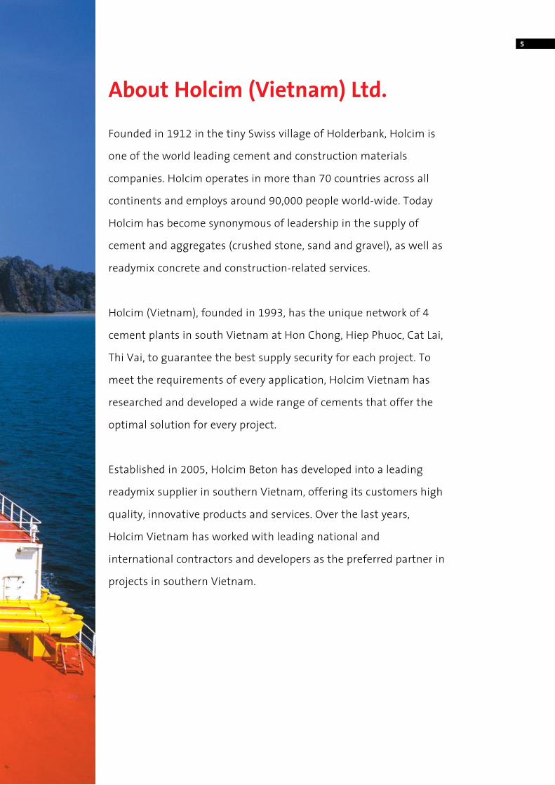
Founded in 1912 in the tiny Swiss village of Holderbank, Holcim is
one of the world leading cement and construction materials
companies. Holcim operates in more than 70 countries across all
continents and employs around 90,000 people world-wide. Today
Holcim has become synonymous of leadership in the supply of
cement and aggregates (crushed stone, sand and gravel), as well as
readymix concrete and construction-related services.
Holcim (Vietnam), founded in 1993, has the unique network of 4
cement plants in south Vietnam at Hon Chong, Hiep Phuoc, Cat Lai,
Thi Vai, to guarantee the best supply security for each project. To
meet the requirements of every application, Holcim Vietnam has
researched and developed a wide range of cements that offer the
optimal solution for every project.
Established in 2005, Holcim Beton has developed into a leading
readymix supplier in southern Vietnam, offering its customers high
quality, innovative products and services. Over the last years,
Holcim Vietnam has worked with leading national and
international contractors and developers as the preferred partner in
projects in southern Vietnam.

6
7
Preface
To develop Vietnam in the 21st century and to meet the requirements of modern society, many high rise buildings and infrastructure projects, like ports, roads, bridges… are being designed and constructed by national and international developers, designers and contractors.
These structures are expected to be in service for long time, sometimes for 100 years, with low maintenance costs. The durability of concrete as building material is a key element for long lasting projects. This Technical Manual offers an overview of good practices in concrete as well as an overview of relevant Vietnamese and international standards.
A better understanding of cement/concrete standards can make it easier for designers, consultants and contractors to choose the type of cement and concrete, suitable for their specific project. With good concrete practice at the jobsite, the high quality building material “concrete” will be molded and transformed into long lasting concrete structures, to build Vietnam for future generations.
As the different standards are complex to summarize and the construction industry changes quickly in Vietnam, it is possible that there are inaccuracies in this Technical Manual. We are looking forward to any feedback or input for improvement on [email protected].
Yours sincerely,
Pieter KeppensTechnical Marketing Manager
8 Index
Chapter ICement & Concrete 11A. Components of concrete 11
1. Cement 112. Mixing water 123. Fine aggregate 134. Coarse aggregate 145. Admixtures 166. Additions 17
B. From fresh concrete to hardened concrete 201. Composition of concrete 202. Workability 233. Concrete strength 274. Special characteristics 335. Production and transport 376. Placing and compaction 387. Concreting in hot weather 418. Pumped concrete 439. Curing 4510. Influence of formwork 47
Chapter IIApplications with specific requirements 49A. Infrastructure 49
1. Introduction 492. Cement for infrastructure 49
B. Aggressive environments 501. Introduction 502. Sulfate resistant Portland cement 503. Sulfate resistant blended cements 51
C. Massive structure 521. Introduction 522. Cement for massive structures 523. Concrete for massive structures 53
D. High strength concrete 541. Introduction 542. Production and use of high strength concrete 55
E. Very flowable and self-compacting concrete 561. Introduction 562. Production of very flowable / self-compacting concrete 57
F. Cement treated aggregates 581. Introduction 582. Cement for treated aggregates 583. Testing procedure for cement treated aggregates 594. Optimization of cement treated aggregates 61
9
Chapter IIICauses and prevention of concrete defects 62A. Segregation of concrete 63
B. Cracking 641. Plastic settlement cracks 652. Plastic shrinkage cracks 663. Surface crazing 674. Drying shrinkage cracks 675. Early thermal cracking 68
C. Carbonation and corrosion of reinforcement 69
D. Degradation in seawater environment 701. Chloride-induced corrosion of the steel reinforcement 702. Attack by sulfates from seawater 713. Preventive measures 71
E. Chemical attack 721. Classification 722. Preventive measures 73
F. Alkali – Aggregate Reaction 74
G. Fire Resistance 751. Concrete in fire 752. Preventive measures 75
Chapter IVOverview of cement & concrete standards 76A. Cement 77
Vietnamese standards – TCVN 77American standards – ASTM 83European standards – EN 86
B. Concrete 89Vietnamese standards – TCVN 89American standards – ASTM 91European standards – EN 93British standards – BS 95
C. Recommendation for limiting values of concrete composition 97Chloride - induced corrosion in sea water 97Aggressive chemical environments 97
Reference 98

10
11
1. CementGeneralCement is a hydraulic binder – a material that hardens after being mixed with water, either in the air or under water. The hardened cement paste is water-resistant and possesses high strength. For all concrete without specific requirements, the type of cement generally used in Vietnam is a blended Portland cement, type PCB 40, according to the Vietnamese standard TCVN 6260. For plaster/mortar in rural areas, PCB30, a lower strength class, is sometimes used as well.
Several types of blending materials are used, like limestone, puzzolan or slag, depending on the locally available materials.
International standards, comparable to TCVN 6260, are:• American Standard ASTM C1157: type GU
(General Use)
• European Standard EN 197-1: CEM II/A or CEM II/B 42.5
Other types of cement, which are used worldwide, like
• Ordinary Portland Cement OPC (TCVN 2682, ASTM C150, EN 197-1 CEM I)
• Blast Furnace Slag cement (TCVN 4316, ASTM C1157, EN 197-1 CEM III)
are not available in Vietnam as general use cement.
The test methods of the TCVN standard are very close to the EN standard, with the correction of testing temperature (27oC instead of 20oC), to take the local climate conditions into account.
The ASTM standards use a completely different set of testing methods and the requirements cannot be compared to the TCVN/EN standards. In Vietnam, several 3rd party laboratories are equipped to test cement according to TCVN & ASTM, but not according to the EN standard.
Testing cement quality and conformityThe quality and conformity of Vietnam cements are assured through three types of control:
• Control of the product in the plant
• An certified quality-management system
• External monitoring
Control of the product in the plant At each step of the cement production, from the quarry to cement delivery, material specimens are collected for analysis. Gap-free monitoring of production ensures uniform, high-quality cement. The testing methods for cement are described in standard TCVN 6017:1995 and ISO 9597:2008.
Quality management systemMost cement plants have established a quality management system and all are certified according to the ISO 9001:2008 series of standards. Some cement plants also have a testing center in series of VILAS according to ISO 17025. This ensures that all operational processes are standardized, traceable, and transparent.
External monitoringIn-house testing is supplemented by external monitoring. External monitoring is carried out by a testing institute accredited for testing cement. In the south part of Vietnam, the most referenced external monitoring is Quality Assurance and Testing Center 3 (QUATEST 3). From November 2012, every cement in Vietnam has to carry the CR quality label. Cement storage and shelf lifeIf cement is stored unprotected for a long time, it absorbs moisture, which leads to lumps and may reduce the strength development. If lumps can be crushed between the fingers, the loss of strength will be negligible.
Cement can be stored for a limited time in silo or bags. Bag cement is best stored in dry shelter. Bags stacked temporarily outdoors must be placed on timber sleepers for ventilation. The plastic cover must not be allowed to contact the cement bags, because condensation would wet the bags.
Chapter I: Cement & ConcreteA. Components of concrete
Holcim recommendationFor general use concrete, standard cement offers the best supply security for any project:
• TCVN 6260:2009 – PCB 40
• ASTM C1157:2008 – GU
12
2. Mixing waterWater for mixing concrete and mortar must comply with TCXDVN 302:2004 or ASTM C1602. Water that meets these requirements, can be used for washing aggregate and curing concrete sample. According to these standards, drinking water can be used as mixing water without testing. Water from rivers and canals is in most cases not appropriate to make concrete. The use of seawater in reinforced concrete is strictly forbidden.
GeneralMixing water is the total amount of water contained in fresh concrete. It is the sum of: • The water added directly to the mix • The surface moisture of the aggregates • The water content of the concrete admixtures
and additions, if applicable(silica fume, pigment in suspension, etc.)
Mixing water has two functions in concrete technology. It is required for hydration of the cement, and for the production of a plastic concrete that can be well compacted.
Requirements for mixing waterAccording to TCXDVN 302:2004, mixing water must meet these following requirements:• Does not contain oil scum and oily film• Organic content < 15mg/l• 4 < pH < 12.5• Color free• Depending on the type of concrete, sulfate and
chloride content must follow the requirements in Table I.1 (TCXDVN 302 : 2004).
Chapter I: Cement & Concrete A. Components of concrete
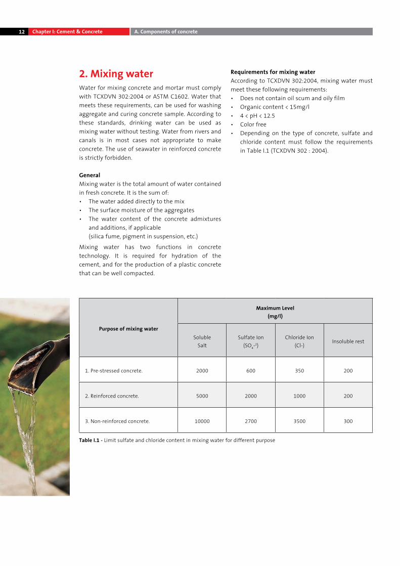
Table I.1 - Limit sulfate and chloride content in mixing water for different purpose
Purpose of mixing water
Maximum Level (mg/l)
SolubleSalt
Sulfate Ion (SO4-2)
Chloride Ion (Cl-)
Insoluble rest
1. Pre-stressed concrete. 2000 600 350 200
2. Reinforced concrete. 5000 2000 1000 200
3. Non-reinforced concrete. 10000 2700 3500 300
13Chapter I: Cement & Concrete A. Components of concrete
3. Fine Aggregate GradingFine aggregate shall consist of natural sand, crushed sand, or a combination thereof. For concrete production, fine aggregates must comply with TCVN 7570 : 2006 or ASTM C33 (Standard Specification for Concrete Aggregates). In the south of Vietnam, 3 sources of fine aggregates are used in concrete (FM = fineness modulus):
• Sand from Dong Nai river : FM = 2.40 (good – not available in significant quantity)
• Sand from Mekong river : FM = 1.1 -1.6 (too fine)
• Manufactured (crushed) sand : FM = 4.0 (too coarse)
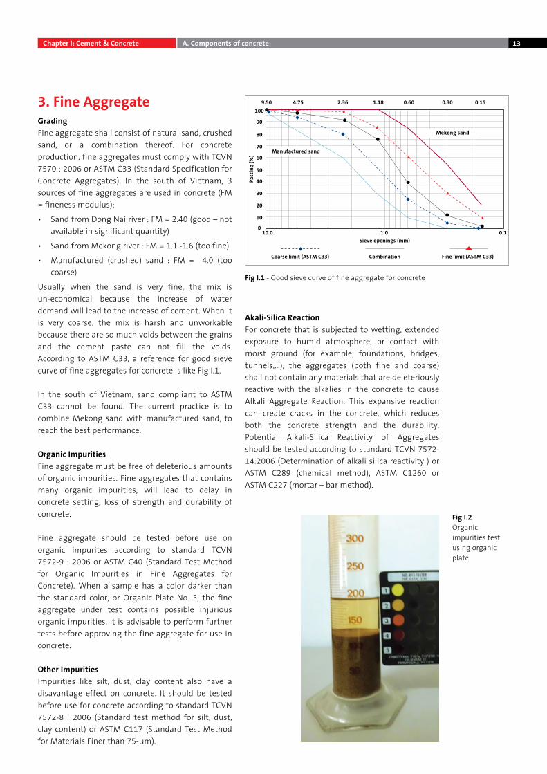
Usually when the sand is very fine, the mix is un-economical because the increase of water demand will lead to the increase of cement. When it is very coarse, the mix is harsh and unworkable because there are so much voids between the grains and the cement paste can not fill the voids. According to ASTM C33, a reference for good sieve curve of fine aggregates for concrete is like Fig I.1.
In the south of Vietnam, sand compliant to ASTM C33 cannot be found. The current practice is to combine Mekong sand with manufactured sand, to reach the best performance.
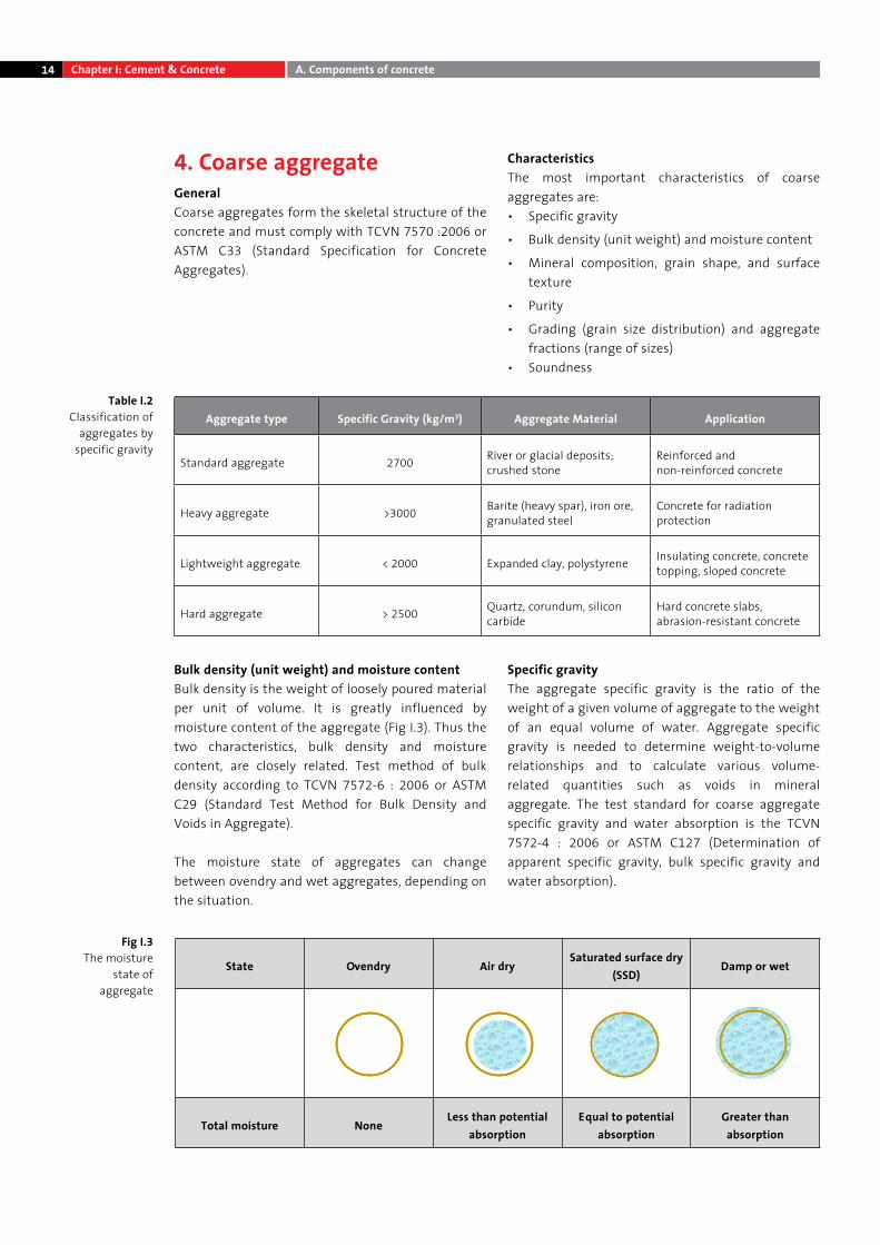
Organic ImpuritiesFine aggregate must be free of deleterious amounts of organic impurities. Fine aggregates that contains many organic impurities, will lead to delay in concrete setting, loss of strength and durability of concrete.
Fine aggregate should be tested before use on organic impurites according to standard TCVN 7572-9 : 2006 or ASTM C40 (Standard Test Method for Organic Impurities in Fine Aggregates for Concrete). When a sample has a color darker than the standard color, or Organic Plate No. 3, the fine aggregate under test contains possible injurious organic impurities. It is advisable to perform further tests before approving the fine aggregate for use in concrete.
Other ImpuritiesImpurities like silt, dust, clay content also have a disavantage effect on concrete. It should be tested before use for concrete according to standard TCVN 7572-8 : 2006 (Standard test method for silt, dust, clay content) or ASTM C117 (Standard Test Method for Materials Finer than 75-μm).
Akali-Silica ReactionFor concrete that is subjected to wetting, extended exposure to humid atmosphere, or contact with moist ground (for example, foundations, bridges, tunnels,…), the aggregates (both fine and coarse) shall not contain any materials that are deleteriously reactive with the alkalies in the concrete to cause Alkali Aggregate Reaction. This expansive reaction can create cracks in the concrete, which reduces both the concrete strength and the durability. Potential Alkali-Silica Reactivity of Aggregates should be tested according to standard TCVN 7572-14:2006 (Determination of alkali silica reactivity ) or ASTM C289 (chemical method), ASTM C1260 or ASTM C227 (mortar – bar method).
Fig I.2Organic impurities test using organic plate.
Fig I.1 - Good sieve curve of fine aggregate for concrete
10
0
20
30
40
50
60
70
80
90
1009.50
10.0 1.0Sieve openings (mm)
Fine limit (ASTM C33)CombinationCoarse limit (ASTM C33)Pa
ssin
g (%
)
0.1
4.75 2.36 1.18 0.60 0.30 0.15
Manufactured sand
Mekong sand
14
4. Coarse aggregateGeneral Coarse aggregates form the skeletal structure of the concrete and must comply with TCVN 7570 :2006 or ASTM C33 (Standard Specification for Concrete Aggregates).
CharacteristicsThe most important characteristics of coarse aggregates are: • Specific gravity
• Bulk density (unit weight) and moisture content
• Mineral composition, grain shape, and surface texture
• Purity
• Grading (grain size distribution) and aggregate fractions (range of sizes)
• Soundness
Table I.2 Classification of
aggregates by specific gravity
State Ovendry Air drySaturated surface dry
(SSD)Damp or wet
Total moisture NoneLess than potential
absorptionEqual to potential
absorptionGreater than
absorption
Fig I.3The moisture
state of aggregate
Bulk density (unit weight) and moisture contentBulk density is the weight of loosely poured material per unit of volume. It is greatly influenced by moisture content of the aggregate (Fig I.3). Thus the two characteristics, bulk density and moisture content, are closely related. Test method of bulk density according to TCVN 7572-6 : 2006 or ASTM C29 (Standard Test Method for Bulk Density and Voids in Aggregate).
The moisture state of aggregates can change between ovendry and wet aggregates, depending on the situation.
Specific gravity The aggregate specific gravity is the ratio of the weight of a given volume of aggregate to the weight of an equal volume of water. Aggregate specific gravity is needed to determine weight-to-volume relationships and to calculate various volume-related quantities such as voids in mineral aggregate. The test standard for coarse aggregate specific gravity and water absorption is the TCVN 7572-4 : 2006 or ASTM C127 (Determination of apparent specific gravity, bulk specific gravity and water absorption).
Aggregate type Specific Gravity (kg/m3) Aggregate Material Application
Standard aggregate 2700 River or glacial deposits; crushed stone
Reinforced and non-reinforced concrete
Heavy aggregate >3000 Barite (heavy spar), iron ore, granulated steel
Concrete for radiation protection
Lightweight aggregate < 2000 Expanded clay, polystyrene Insulating concrete, concrete topping, sloped concrete
Hard aggregate > 2500 Quartz, corundum, silicon carbide
Hard concrete slabs, abrasion-resistant concrete
Chapter I: Cement & Concrete A. Components of concrete
15
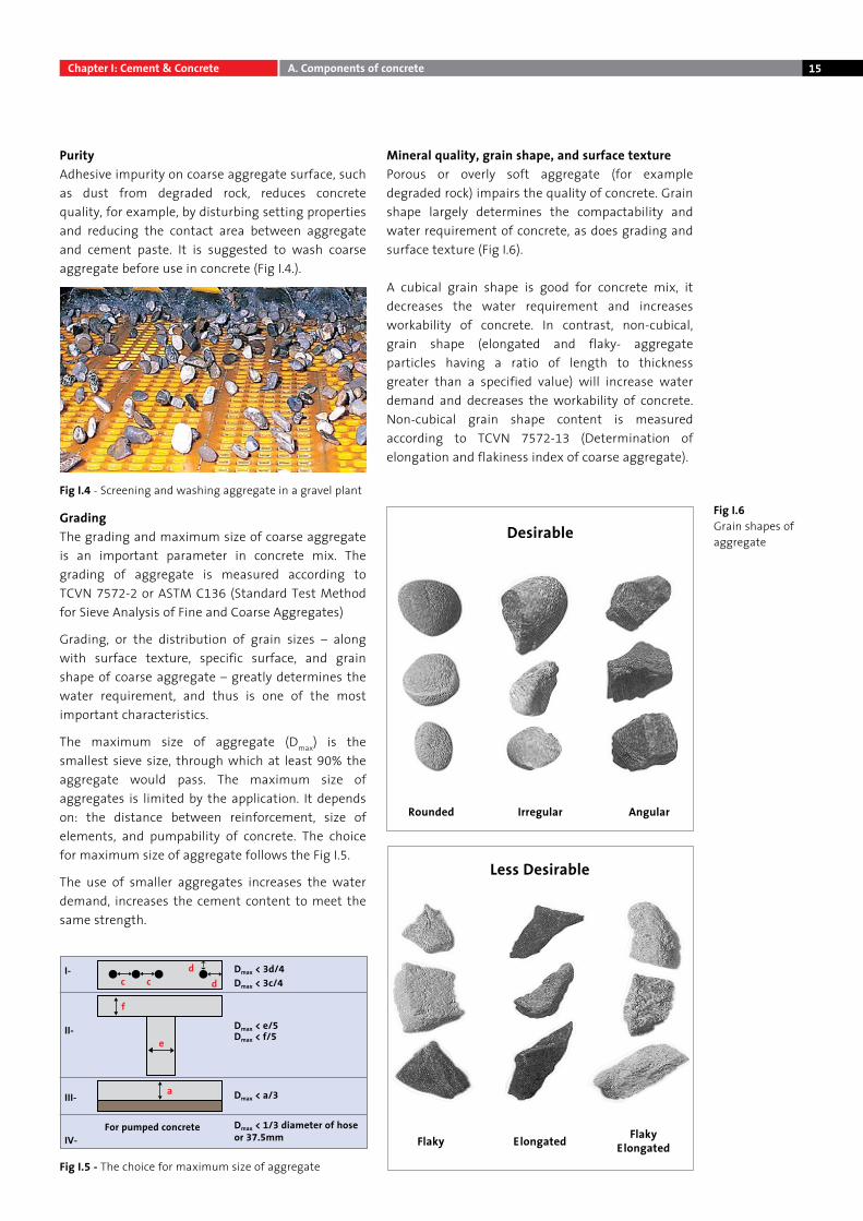
PurityAdhesive impurity on coarse aggregate surface, such as dust from degraded rock, reduces concrete quality, for example, by disturbing setting properties and reducing the contact area between aggregate and cement paste. It is suggested to wash coarse aggregate before use in concrete (Fig I.4.).
GradingThe grading and maximum size of coarse aggregate is an important parameter in concrete mix. The grading of aggregate is measured according to TCVN 7572-2 or ASTM C136 (Standard Test Method for Sieve Analysis of Fine and Coarse Aggregates)
Grading, or the distribution of grain sizes – along with surface texture, specific surface, and grain shape of coarse aggregate – greatly determines the water requirement, and thus is one of the most important characteristics.
The maximum size of aggregate (Dmax) is the smallest sieve size, through which at least 90% the aggregate would pass. The maximum size of aggregates is limited by the application. It depends on: the distance between reinforcement, size of elements, and pumpability of concrete. The choice for maximum size of aggregate follows the Fig I.5.
The use of smaller aggregates increases the water demand, increases the cement content to meet the same strength.
Mineral quality, grain shape, and surface texturePorous or overly soft aggregate (for example degraded rock) impairs the quality of concrete. Grain shape largely determines the compactability and water requirement of concrete, as does grading and surface texture (Fig I.6).
A cubical grain shape is good for concrete mix, it decreases the water requirement and increases workability of concrete. In contrast, non-cubical, grain shape (elongated and flaky- aggregate particles having a ratio of length to thickness greater than a specified value) will increase water demand and decreases the workability of concrete. Non-cubical grain shape content is measured according to TCVN 7572-13 (Determination of elongation and flakiness index of coarse aggregate).
Fig I.5 - The choice for maximum size of aggregate
Fig I.6 Grain shapes of aggregate
Rounded Irregular Angular
Desirable
Less Desirable
Flaky ElongatedFlaky Elongated
Fig I.4 - Screening and washing aggregate in a gravel plant
I- Dmax < 3d/4
Dmax < e/5Dmax < f/5
Dmax < a/3
Dmax < 1/3 diameter of hoseor 37.5mm
For pumped concrete
c
f
c
e
a
dd
Dmax < 3c/4
II-
III-
IV-
Chapter I: Cement & Concrete A. Components of concrete
16
5. AdmixturesDefinition and classificationConcrete admixtures are chemical substances that are added to concrete to change, through chemical and/or physical action, some of its properties, such as workability, setting, hardening.
In Vietnam, the performance requirements for different types of admixtures comply with standards TCVN 8826 : 2011 or ASTM C494 (Standard Specification for Chemical Admixtures for Concrete).
DosageAdmixtures are added to concrete mainly in liquid form and in very small amounts. The dosage is generally about 0.4 to 2% in relation to the weight of cement. In certain cases the amount will be recommended by the manufacturer. If the dosage exceeds about 1%, the water introduced with the admixture, must be considered as part of concrete mixing water. Too low dosage can reduce significantly the desired effect, and too high dosage can produce unwanted effects such as retarded setting or loss of compressive strength.
The most important and common types of admixturesAccording to ASTM C494, there are seven types of admixture (from type A through type G). In Vietnam, three types are commonly used:
a/ Water reducing and retarding admixture.
This type of admixture, based on lignosulphonate, can be used at dosage 0.4 - 0.6% to reduce the quantity of water required (6% - 12%).
Water reducing admixtures require less water to make a concrete of equal slump which improves the concrete strength, or increase the slump of concrete at the same water content.
Retarding admixture is useful for concrete that has to be transported over long distances, requires a long slump retention and to retard the setting time of concrete when placed at high temperatures.
b/ Mid-range water reducing admixture.
This type of admixture, based on napthalene sulfonate, can be used at dosage 0.7 – 1.2% to decreases the water requirements by about 15 – 25%.
Mid-range water reducers allow larger water reduction to increase strength or slump/slump retention at jobsite. They can achieve a specific consistency and workability at a greatly reduced amount of water. As with most types of admixtures, napthalenes can significantly delay the initial setting time of concrete, depending on the admixture formulation.
c/ High-range water reducing admixture
This type of admixture is based on polycarboxylate base. Common dosages are between 0.8 – 1.8%, depending on the supplier recommendation. This type of admixture can reduce the quantity of mixing water required (20 - 35%) to produce concrete with high consistency, better workability and high strength. The optimal dosage needs to be determined based on the particular concrete mix and specific requirements.
Other type of admixtures
Many other types of admixture for concrete are available:
• Accelerators
• Air entrainer admixture
• Corrosion inhibitor
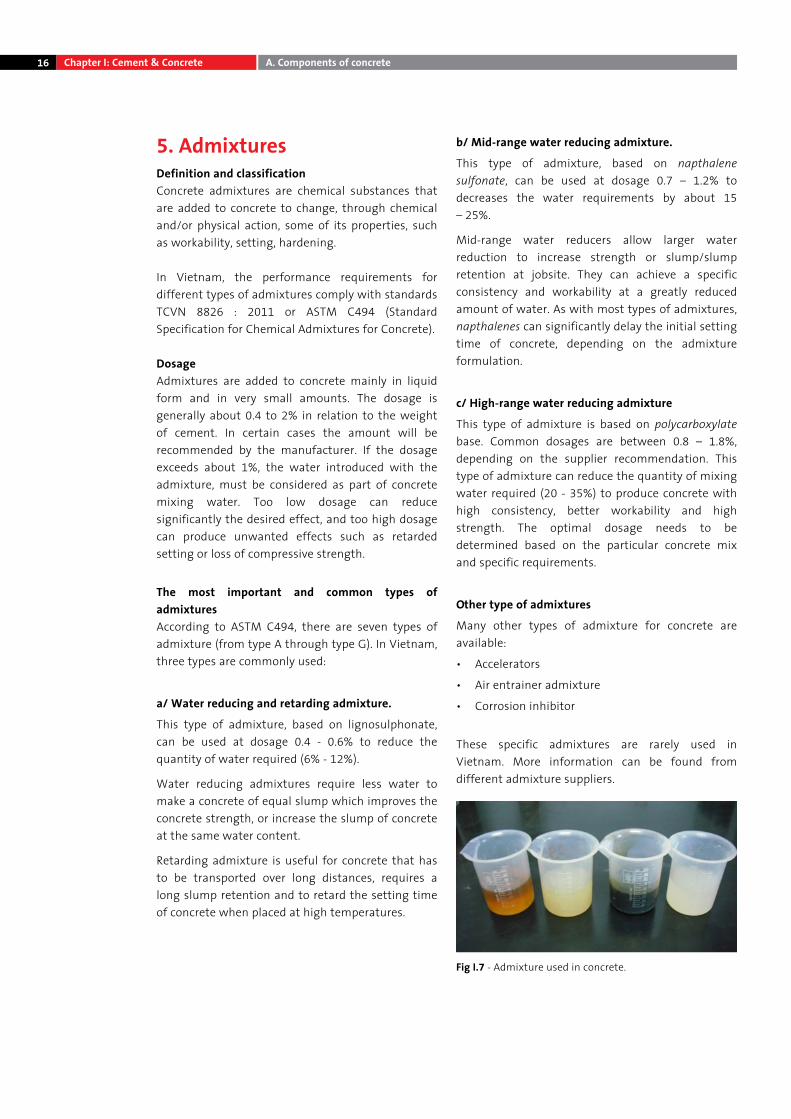
These specific admixtures are rarely used in Vietnam. More information can be found from different admixture suppliers.
Fig I.7 - Admixture used in concrete.
Chapter I: Cement & Concrete A. Components of concrete
17
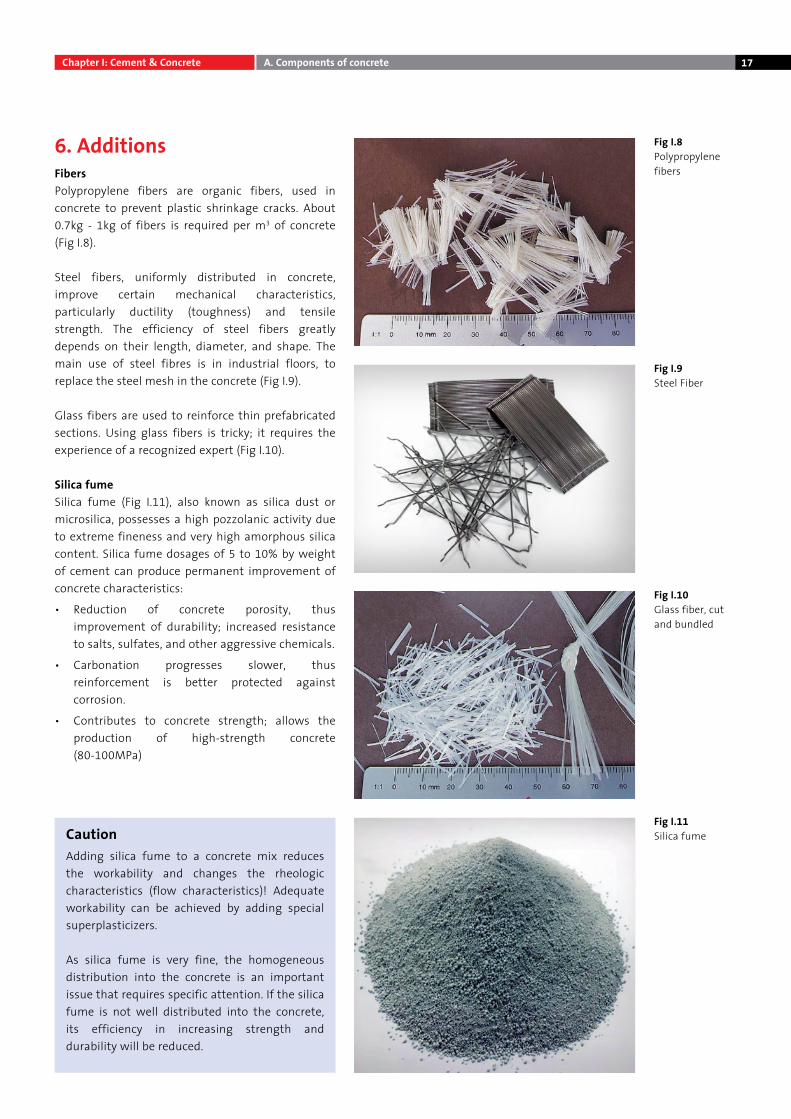
6. AdditionsFibersPolypropylene fibers are organic fibers, used in concrete to prevent plastic shrinkage cracks. About 0.7kg - 1kg of fibers is required per m3 of concrete (Fig I.8).
Steel fibers, uniformly distributed in concrete, improve certain mechanical characteristics, particularly ductility (toughness) and tensile strength. The efficiency of steel fibers greatly depends on their length, diameter, and shape. The main use of steel fibres is in industrial floors, to replace the steel mesh in the concrete (Fig I.9).
Glass fibers are used to reinforce thin prefabricated sections. Using glass fibers is tricky; it requires the experience of a recognized expert (Fig I.10).
Silica fumeSilica fume (Fig I.11), also known as silica dust or microsilica, possesses a high pozzolanic activity due to extreme fineness and very high amorphous silica content. Silica fume dosages of 5 to 10% by weight of cement can produce permanent improvement of concrete characteristics:
• Reduction of concrete porosity, thus improvement of durability; increased resistance to salts, sulfates, and other aggressive chemicals.
• Carbonation progresses slower, thus reinforcement is better protected against corrosion.
• Contributes to concrete strength; allows the production of high-strength concrete (80-100MPa)
Fig I.8 Polypropylene fibers
Fig I.9 Steel Fiber
Fig I.10 Glass fiber, cut and bundled
Fig I.11 Silica fumeCaution
Adding silica fume to a concrete mix reduces the workability and changes the rheologic characteristics (flow characteristics)! Adequate workability can be achieved by adding special superplasticizers.
As silica fume is very fine, the homogeneous distribution into the concrete is an important issue that requires specific attention. If the silica fume is not well distributed into the concrete, its efficiency in increasing strength and durability will be reduced.
Chapter I: Cement & Concrete A. Components of concrete
18
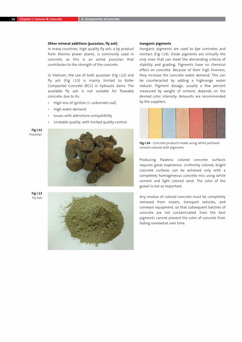
Other mineral additions (puzzolan, fly ash)In many countries, high quality fly ash, a by product from thermo power plants, is commonly used in concrete, as this is an active puzzolan that contributes to the strength of the concrete. In Vietnam, the use of both puzzolan (Fig I.12) and fly ash (Fig I.13) is mainly limited to Roller Compacted Concrete (RCC) in hydraulic dams. The available fly ash is not suitable for flowable concrete, due to its:
• High loss of ignition (= unburned coal)
• High water demand
• Issues with admixture compatibility
• Unstable quality, with limited quality control.
Inorganic pigmentsInorganic pigments are used to dye concretes and mortars (Fig I.14). Oxide pigments are virtually the only ones that can meet the demanding criteria of stability and grading. Pigments have no chemical effect on concrete. Because of their high fineness, they increase the concrete water demand. This can be counteracted by adding a highrange water reducer. Pigment dosage, usually a few percent measured by weight of cement, depends on the desired color intensity. Amounts are recommended by the suppliers.
Producing flawless colored concrete surfaces requires great experience. Uniformly colored, bright concrete surfaces can be achieved only with a completely homogeneous concrete mix using white cement and light colored sand. The color of the gravel is not so important.
Any residue of colored concrete must be completely removed from mixers, transport vehicles, and conveyor equipment, so that subsequent batches of concrete are not contaminated. Even the best pigments cannot prevent the color of concrete from fading somewhat over time.
Fig I.14 - Concrete products made using white portland cement colored with pigments
Fig I.12 Puzzolan
Fig I.13 Fly Ash
Chapter I: Cement & Concrete A. Components of concrete
19Cement & Concrete Concrete component
20 B. From fresh concrete to hardened concrete
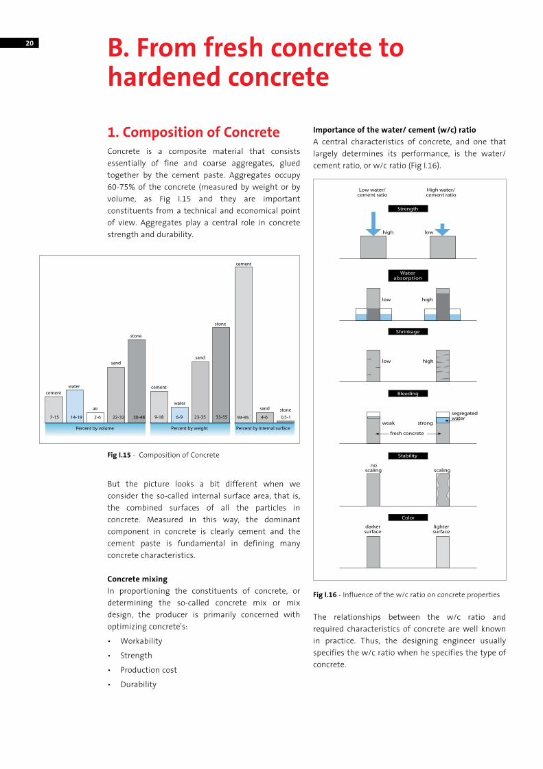
1. Composition of ConcreteConcrete is a composite material that consists essentially of fine and coarse aggregates, glued together by the cement paste. Aggregates occupy 60-75% of the concrete (measured by weight or by volume, as Fig I.15 and they are important constituents from a technical and economical point of view. Aggregates play a central role in concrete strength and durability.
But the picture looks a bit different when we consider the so-called internal surface area, that is, the combined surfaces of all the particles in concrete. Measured in this way, the dominant component in concrete is clearly cement and the cement paste is fundamental in defining many concrete characteristics.
Concrete mixingIn proportioning the constituents of concrete, or determining the so-called concrete mix or mix design, the producer is primarily concerned with optimizing concrete's:
• Workability
• Strength
• Production cost
• Durability
Importance of the water/ cement (w/c) ratioA central characteristics of concrete, and one that largely determines its performance, is the water/cement ratio, or w/c ratio (Fig I.16).
The relationships between the w/c ratio and required characteristics of concrete are well known in practice. Thus, the designing engineer usually specifies the w/c ratio when he specifies the type of concrete.
Fig I.15 - Composition of Concrete
Fig I.16 - Influence of the w/c ratio on concrete properties
21
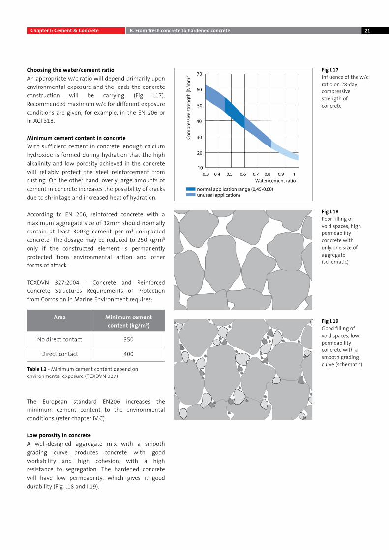
Choosing the water/cement ratioAn appropriate w/c ratio will depend primarily upon environmental exposure and the loads the concrete construction will be carrying (Fig I.17). Recommended maximum w/c for different exposure conditions are given, for example, in the EN 206 or in ACI 318.
Minimum cement content in concreteWith sufficient cement in concrete, enough calcium hydroxide is formed during hydration that the high alkalinity and low porosity achieved in the concrete will reliably protect the steel reinforcement from rusting. On the other hand, overly large amounts of cement in concrete increases the possibility of cracks due to shrinkage and increased heat of hydration.
According to EN 206, reinforced concrete with a maximum aggregate size of 32mm should normally contain at least 300kg cement per m3 compacted concrete. The dosage may be reduced to 250 kg/m3 only if the constructed element is permanently protected from environmental action and other forms of attack.
TCXDVN 327:2004 - Concrete and Reinforced Concrete Structures Requirements of Protection from Corrosion in Marine Environment requires:
The European standard EN206 increases the minimum cement content to the environmental conditions (refer chapter IV.C)
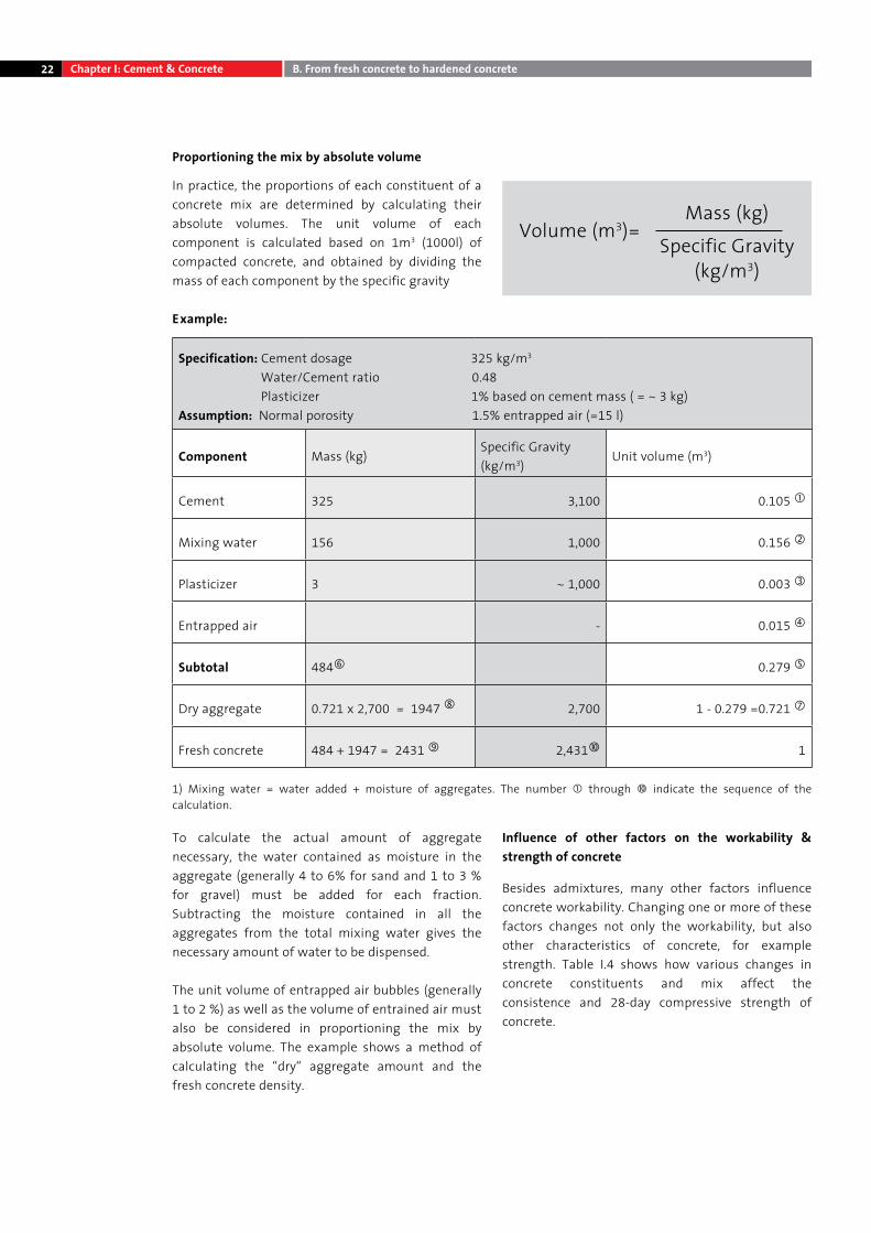
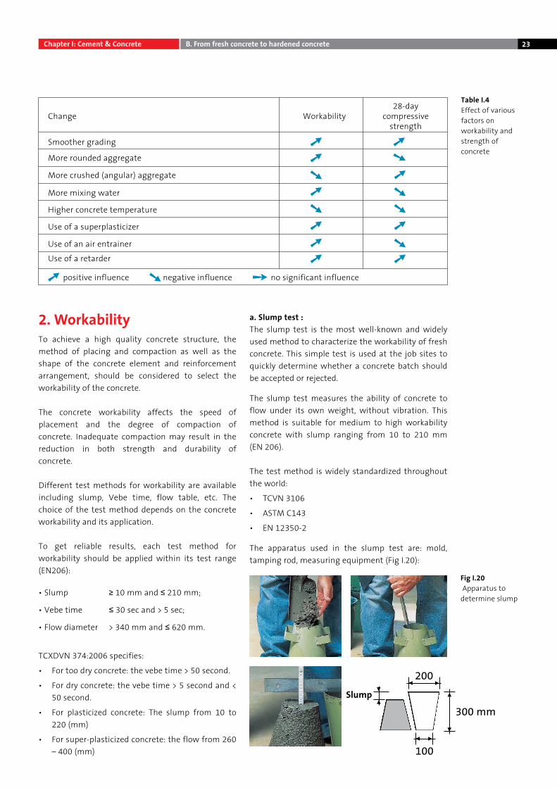
Low porosity in concreteA well-designed aggregate mix with a smooth grading curve produces concrete with good workability and high cohesion, with a high resistance to segregation. The hardened concrete will have low permeability, which gives it good durability (Fig I.18 and I.19).
Fig I.17 Influence of the w/c ratio on 28-day compressive strength of concrete
Fig I.18Poor filling of void spaces, high permeability concrete with only one size of aggregate (schematic)
Fig I.19Good filling of void spaces, low permeability concrete with a smooth grading curve (schematic)
Area Minimum cement content (kg/m3)
No direct contact 350
Direct contact 400
Table I.3 - Minimum cement content depend on environmental exposure (TCXDVN 327)
Chapter I: Cement & Concrete B. From fresh concrete to hardened concrete
22 Chapter I: Cement & Concrete B. From fresh concrete to hardened concrete
Proportioning the mix by absolute volume
In practice, the proportions of each constituent of a concrete mix are determined by calculating their absolute volumes. The unit volume of each component is calculated based on 1m3 (1000l) of compacted concrete, and obtained by dividing the mass of each component by the specific gravity
Example:
Volume (m3)=Mass (kg)
Specific Gravity(kg/m3)
Specification: Cement dosage 325 kg/m3
Water/Cement ratio 0.48 Plasticizer 1% based on cement mass ( = ~ 3 kg)Assumption: Normal porosity 1.5% entrapped air (=15 l)
Component Mass (kg)Specific Gravity (kg/m3)
Unit volume (m3)
Cement 325 3,100 0.105
Mixing water 156 1,000 0.156
Plasticizer 3 ~ 1,000 0.003
Entrapped air - 0.015
Subtotal 484 0.279
Dry aggregate 0.721 x 2,700 = 1947 2,700 1 - 0.279 =0.721
Fresh concrete 484 + 1947 = 2431 2,431 1
1) Mixing water = water added + moisture of aggregates. The number through indicate the sequence of the calculation.
To calculate the actual amount of aggregate necessary, the water contained as moisture in the aggregate (generally 4 to 6% for sand and 1 to 3 % for gravel) must be added for each fraction. Subtracting the moisture contained in all the aggregates from the total mixing water gives the necessary amount of water to be dispensed.
The unit volume of entrapped air bubbles (generally 1 to 2 %) as well as the volume of entrained air must also be considered in proportioning the mix by absolute volume. The example shows a method of calculating the “dry“ aggregate amount and the fresh concrete density.
Influence of other factors on the workability & strength of concrete
Besides admixtures, many other factors influence concrete workability. Changing one or more of these factors changes not only the workability, but also other characteristics of concrete, for example strength. Table I.4 shows how various changes in concrete constituents and mix affect the consistence and 28-day compressive strength of concrete.
23
Table I.4Effect of various factors on workability and strength of concrete
Fig I.20 Apparatus to determine slump
2. WorkabilityTo achieve a high quality concrete structure, the method of placing and compaction as well as the shape of the concrete element and reinforcement arrangement, should be considered to select the workability of the concrete.
The concrete workability affects the speed of placement and the degree of compaction of concrete. Inadequate compaction may result in the reduction in both strength and durability of concrete.
Different test methods for workability are available including slump, Vebe time, flow table, etc. The choice of the test method depends on the concrete workability and its application.
To get reliable results, each test method for workability should be applied within its test range (EN206):
TCXDVN 374:2006 specifies:
• For too dry concrete: the vebe time > 50 second.
• For dry concrete: the vebe time > 5 second and < 50 second.
• For plasticized concrete: The slump from 10 to 220 (mm)
• For super-plasticized concrete: the flow from 260 – 400 (mm)
a. Slump test :The slump test is the most well-known and widely used method to characterize the workability of fresh concrete. This simple test is used at the job sites to quickly determine whether a concrete batch should be accepted or rejected.
The slump test measures the ability of concrete to flow under its own weight, without vibration. This method is suitable for medium to high workability concrete with slump ranging from 10 to 210 mm (EN 206).
The test method is widely standardized throughout the world:
• TCVN 3106
• ASTM C143
• EN 12350-2
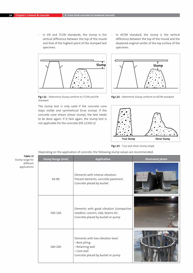
The apparatus used in the slump test are: mold, tamping rod, measuring equipment (Fig I.20):
Workability28-day
compressive strength
Change
• Slump ≥ 10 mm and ≤ 210 mm;
• Vebe time ≤ 30 sec and > 5 sec;
• Flow diameter > 340 mm and ≤ 620 mm.
More rounded aggregate
Smoother grading
positive influence negative influence no significant influence
More crushed (angular) aggregate
More mixing water
Higher concrete temperature
Use of a superplasticizer
Use of an air entrainer
Use of a retarder
Chapter I: Cement & Concrete B. From fresh concrete to hardened concrete
24
- In EN and TCVN standards, the slump is the vertical difference between the top of the mould and that of the highest point of the slumped test specimen.
- In ASTM standard, the slump is the vertical difference between the top of the mould and the displaced original center of the top surface of the specimen.
The slump test is only valid if the concrete cone stays visible and symmetrical (true slump). If the concrete cone shears (shear slump), the test needs to be done again. If it fails again, the slump test is not applicable for the concrete (EN 12350-2)
Depending on the application of concrete, the following slump values are recommended:
Slump Range (mm) Application Illustrated photo
60-80Elements with intense vibration: Precast elements, concrete pavement.Concrete placed by bucket
100-160Elements with good vibration (compaction needles): column, slab, beams etc.Concrete placed by bucket or pump
180-200
Elements with low vibration level:• Bore piling• Retaining wall• Core wallConcrete placed by bucket or pump
Fig I.22 - Determine Slump conform to ASTM standard
Fig I.23 - True and shear slump shape
Fig I.21 - Determine Slump conform to TCVN and EN standard
True Slump Shear Slump
Chapter I: Cement & Concrete B. From fresh concrete to hardened concrete
Table I.5Slump range for
different applications
25
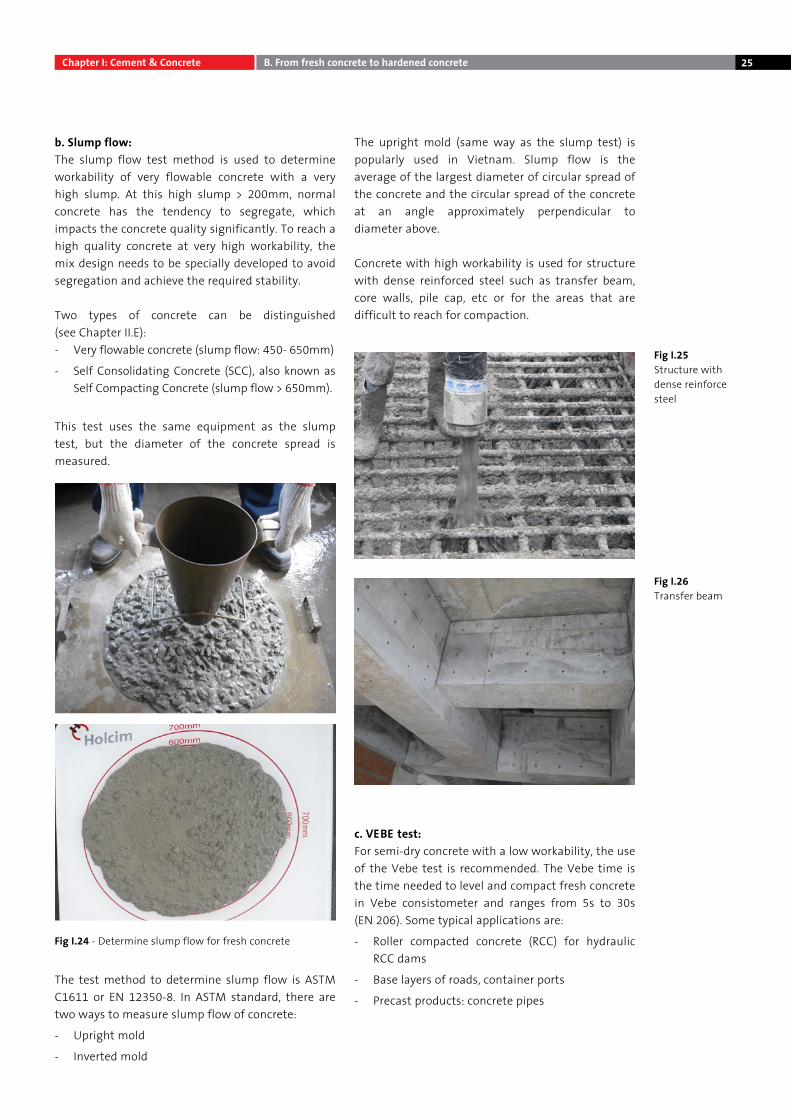
b. Slump flow: The slump flow test method is used to determine workability of very flowable concrete with a very high slump. At this high slump > 200mm, normal concrete has the tendency to segregate, which impacts the concrete quality significantly. To reach a high quality concrete at very high workability, the mix design needs to be specially developed to avoid segregation and achieve the required stability.
Two types of concrete can be distinguished (see Chapter II.E):- Very flowable concrete (slump flow: 450- 650mm)
- Self Consolidating Concrete (SCC), also known as Self Compacting Concrete (slump flow > 650mm).
This test uses the same equipment as the slump test, but the diameter of the concrete spread is measured.
The test method to determine slump flow is ASTM C1611 or EN 12350-8. In ASTM standard, there are two ways to measure slump flow of concrete:
- Upright mold
- Inverted mold
The upright mold (same way as the slump test) is popularly used in Vietnam. Slump flow is the average of the largest diameter of circular spread of the concrete and the circular spread of the concrete at an angle approximately perpendicular to diameter above.
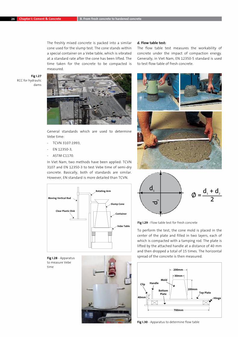
Concrete with high workability is used for structure with dense reinforced steel such as transfer beam, core walls, pile cap, etc or for the areas that are difficult to reach for compaction.
c. VEBE test: For semi-dry concrete with a low workability, the use of the Vebe test is recommended. The Vebe time is the time needed to level and compact fresh concrete in Vebe consistometer and ranges from 5s to 30s (EN 206). Some typical applications are:
- Roller compacted concrete (RCC) for hydraulic RCC dams
- Base layers of roads, container ports
- Precast products: concrete pipes
Fig I.25Structure with dense reinforce steel
Fig I.26Transfer beam
Fig I.24 - Determine slump flow for fresh concrete
Chapter I: Cement & Concrete B. From fresh concrete to hardened concrete
26
The freshly mixed concrete is packed into a similar cone used for the slump test. The cone stands within a special container on a Vebe table, which is vibrated at a standard rate after the cone has been lifted. The time taken for the concrete to be compacted is measured.
General standards which are used to determine Vebe time:
- TCVN 3107:1993,
- EN 12350-3,
- ASTM C1170.
In Viet Nam, two methods have been applied: TCVN 3107 and EN 12350-3 to test Vebe time of semi-dry concrete. Basically, both of standards are similar. However, EN standard is more detailed than TCVN.
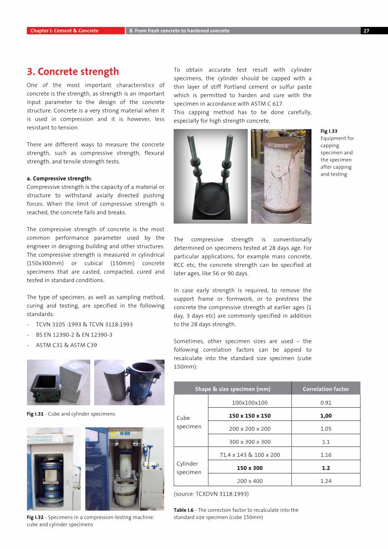
d. Flow table test:The flow table test measures the workability of concrete under the impact of compaction energy. Generally, in Viet Nam, EN 12350-5 standard is used to test flow table of fresh concrete.
To perform the test, the cone mold is placed in the center of the plate and filled in two layers, each of which is compacted with a tamping rod. The plate is lifted by the attached handle at a distance of 40 mm and then dropped a total of 15 times. The horizontal spread of the concrete is then measured.Fig I.28 - Apparatus
to measure Vebe time
Moving Vertical Rod
Rotating Arm
Slump Cone
Container
Vebe Table
Clear Plastic Disk
Mold
Top Plate
Hinge
HandleClip
Bottom Plate
200mm
200mm
700mm
40mm
30mm
Chapter I: Cement & Concrete B. From fresh concrete to hardened concrete
Fig I.27RCC for hydraulic
dams
Fig I.30 - Apparatus to determine flow table
Fig I.29 - Flow table test for fresh concrete
27
3. Concrete strengthOne of the most important characteristics of concrete is the strength, as strength is an important input parameter to the design of the concrete structure. Concrete is a very strong material when it is used in compression and it is however, less resistant to tension.
There are different ways to measure the concrete strength, such as compressive strength, flexural strength, and tensile strength tests.
a. Compressive strength:Compressive strength is the capacity of a material or structure to withstand axially directed pushing forces. When the limit of compressive strength is reached, the concrete fails and breaks.
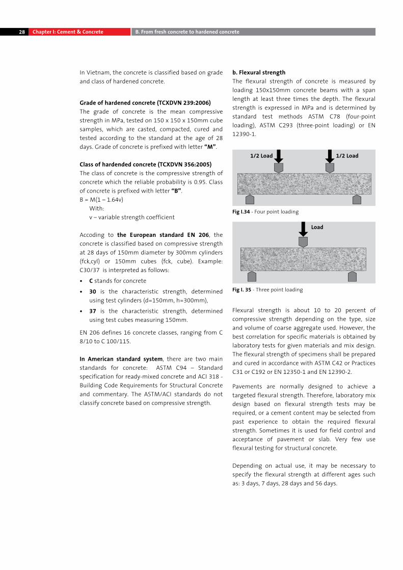
The compressive strength of concrete is the most common performance parameter used by the engineer in designing building and other structures. The compressive strength is measured in cylindrical (150x300mm) or cubical (150mm) concrete specimens that are casted, compacted, cured and tested in standard conditions.
The type of specimen, as well as sampling method, curing and testing, are specified in the following standards:
- TCVN 3105 :1993 & TCVN 3118:1993
- BS EN 12390-2 & EN 12390-3
- ASTM C31 & ASTM C39
To obtain accurate test result with cylinder specimens, the cylinder should be capped with a thin layer of stiff Portland cement or sulfur paste which is permitted to harden and cure with the specimen in accordance with ASTM C 617.This capping method has to be done carefully, especially for high strength concrete.
The compressive strength is conventionally determined on specimens tested at 28 days age. For particular applications, for example mass concrete, RCC etc, the concrete strength can be specified at later ages, like 56 or 90 days.
In case early strength is required, to remove the support frame or formwork, or to prestress the concrete the compressive strength at earlier ages (1 day, 3 days etc) are commonly specified in addition to the 28 days strength.
Sometimes, other specimen sizes are used – the following correlation factors can be appied to recalculate into the standard size specimen (cube 150mm):
(source: TCXDVN 3118:1993)
Fig I.31 - Cube and cylinder specimens
Fig I.32 - Specimens in a compression-testing machine:cube and cylinder specimens
Table I.6 - The correction factor to recalculate into the standard size specimen (cube 150mm)
Fig I.33Equipment for capping specimen and the specimen after capping and testing
Shape & size specimen (mm) Correlation factor
Cube specimen
100x100x100 0.91
150 x 150 x 150 1,00
200 x 200 x 200 1.05
300 x 300 x 300 1.1
Cylinder specimen
71,4 x 143 & 100 x 200 1.16
150 x 300 1.2
200 x 400 1.24
Chapter I: Cement & Concrete B. From fresh concrete to hardened concrete
28
In Vietnam, the concrete is classified based on grade and class of hardened concrete.
Grade of hardened concrete (TCXDVN 239:2006)The grade of concrete is the mean compressive strength in MPa, tested on 150 x 150 x 150mm cube samples, which are casted, compacted, cured and tested according to the standard at the age of 28 days. Grade of concrete is prefixed with letter “M”.
Class of hardended concrete (TCXDVN 356:2005)The class of concrete is the compressive strength of concrete which the reliable probability is 0.95. Class of concrete is prefixed with letter “B”.B = M(1 – 1.64v)
With:v – variable strength coefficient
Accoding to the European standard EN 206, the concrete is classified based on compressive strength at 28 days of 150mm diameter by 300mm cylinders (fck,cyl) or 150mm cubes (fck, cube). Example: C30/37 is interpreted as follows:
• C stands for concrete
• 30 is the characteristic strength, determined using test cylinders (d=150mm, h=300mm),
• 37 is the characteristic strength, determined using test cubes measuring 150mm.
EN 206 defines 16 concrete classes, ranging from C 8/10 to C 100/115.
In American standard system, there are two main standards for concrete: ASTM C94 – Standard specification for ready-mixed concrete and ACI 318 - Building Code Requirements for Structural Concrete and commentary. The ASTM/ACI standards do not classify concrete based on compressive strength.
b. Flexural strengthThe flexural strength of concrete is measured by loading 150x150mm concrete beams with a span length at least three times the depth. The flexural strength is expressed in MPa and is determined by standard test methods ASTM C78 (four-point loading), ASTM C293 (three-point loading) or EN 12390-1.
Flexural strength is about 10 to 20 percent of compressive strength depending on the type, size and volume of coarse aggregate used. However, the best correlation for specific materials is obtained by laboratory tests for given materials and mix design. The flexural strength of specimens shall be prepared and cured in accordance with ASTM C42 or Practices C31 or C192 or EN 12350-1 and EN 12390-2.
Pavements are normally designed to achieve a targeted flexural strength. Therefore, laboratory mix design based on flexural strength tests may be required, or a cement content may be selected from past experience to obtain the required flexural strength. Sometimes it is used for field control and acceptance of pavement or slab. Very few use flexural testing for structural concrete.
Depending on actual use, it may be necessary to specify the flexural strength at different ages such as: 3 days, 7 days, 28 days and 56 days.
Fig I.34 - Four point loading
Fig I. 35 - Three point loading
1/2 Load 1/2 Load
Load
Chapter I: Cement & Concrete B. From fresh concrete to hardened concrete
29
c. Assessment of compressive strength test results
Test methods for sampling & testingGeneral methods for the making of the concrete specimen, their curing and testing are summarized in below table:
The below 3 steps are very important to assure the reliability of the result:
• The sampling of the concrete and the making of the concrete specimens shall be done properly, so that the concrete cubes are representative of the concrete batch. This procedure is sometimes neglected in some job sites, which may lead to low strength of the concrete specimen.
• The curing in water tanks – specific attention needs to be given to the transport of concrete cubes at early age. A careless handling can impact their final strength.
• Finally, the compressive strength of the concrete specimen is determined in the laboratory. Experience shows that the skill of laboratory staff can have a significant impact on the final test result. Special attention is required for the loading speed of the concrete specimen.
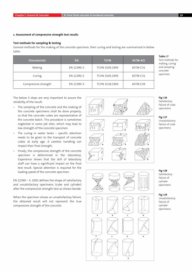
EN 12390 – 3: 2002 defines the shape of satisfactory and unsatisfactory specimens (cube and cylinder) after the compressive strength test as shown beside:
When the specimen shows an unsatisfactory failure, the obtained result will not represent the true compressive strength of the concrete.
Characteristic EN TCVN ASTM-ACI
Making EN 12390-2 TCVN 3105:1993 ASTM C31
Curing EN 12390-2 TCVN 3105:1993 ASTM C31
Compressive strength EN 12390-3 TCVN 3118:1993 ASTM C39
Fig I.36Satisfactory failure of cube specimens
Table I.7Test methods for making, curing and sampling concrete specimen
Fig I.38Satisfactory failure of cylinder specimens
Fig I.39Unsatisfactory failure of cylinder specimens
Fig I.37Unsatisfactory failure of cube specimens
1
4
7 8 9
5
2 3
6
A B C D
HGFE
I J K
Chapter I: Cement & Concrete B. From fresh concrete to hardened concrete
30
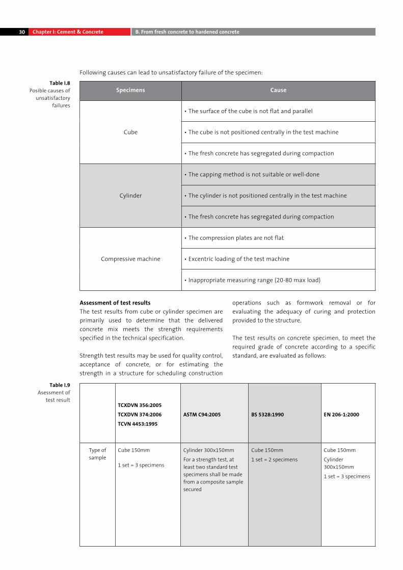
Following causes can lead to unsatisfactory failure of the specimen:
Specimens Cause
Cube
• The surface of the cube is not flat and parallel
• The cube is not positioned centrally in the test machine
• The fresh concrete has segregated during compaction
Cylinder
• The capping method is not suitable or well-done
• The cylinder is not positioned centrally in the test machine
• The fresh concrete has segregated during compaction
Compressive machine
• The compression plates are not flat
• Excentric loading of the test machine
• Inappropriate measuring range (20-80 max load)
Assessment of test resultsThe test results from cube or cylinder specimen are primarily used to determine that the delivered concrete mix meets the strength requirements specified in the technical specification.
Strength test results may be used for quality control, acceptance of concrete, or for estimating the strength in a structure for scheduling construction
operations such as formwork removal or for evaluating the adequacy of curing and protection provided to the structure.
The test results on concrete specimen, to meet the required grade of concrete according to a specific standard, are evaluated as follows:
TCXDVN 356:2005
TCXDVN 374:2006
TCVN 4453:1995
ASTM C94:2005 BS 5328:1990 EN 206-1:2000
Type of sample
Cube 150mm
1 set = 3 specimens
Cylinder 300x150mm
For a strength test, at least two standard test specimens shall be made from a composite sample secured
Cube 150mm
1 set = 2 specimens
Cube 150mm
Cylinder 300x150mm
1 set = 3 specimens
Chapter I: Cement & Concrete B. From fresh concrete to hardened concrete
Table I.8Posible causes of
unsatisfactory failures
Table I.9Asessment of
test result
31
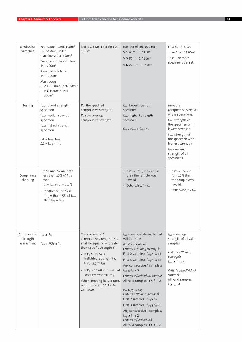
Method of Sampling
Foundation: 1set/100m3
Foundation under machinery: 1set/50m3
Frame and thin structure: 1set /20m3
Base and sub-base: 1set/200m3
Mass pour:• V < 1000m3: 1set/250m3
• V ≥ 1000m3: 1set/ 500m3
Not less than 1 set for each 115m3
number of set required:V ≤ 40m3: 1 / 10m3
V ≤ 80m3: 1 / 20m3
V ≤ 200m3: 1 / 50m3
First 50m3: 3 set
Then 1 set / 150m3
Take 2 or more specimens per set.
Testing fmin : lowest strength specimen
fmed: median strength specimen
fmax: highest strength specimen
∆1 = fmax - fmed ; ∆2 = fmed - fmin
f’c : the specified compressive strength.
f’cr : the average compressive strength.
fmin: lowest strength specimen
fmax: highest strength specimen
fcm = (fmax + fmin) / 2
Measure compressive strength of the specimens.
fmin: strength of the specimen with lowest strength
fmax: strength of the specimen with highest strength
fcm = average strength of all specimens
Compliance checking
• If ∆1 and ∆2 are both less than 15% of fmed, then favg = (fmin + fmed + fmax)/3
• If either ∆1 or ∆2 is larger than 15% of fmed, then favg = fmed
• If (fmax – fmin) / fcm > 15% then the sample was invalid.
• Otherwise, f = fcm
• If (fmax – fmin) / fcm > 15% then the sample was invalid.
• Otherwise, f = fcm
Compressive strength
assessment
favg ≥ fck
fmin ≥ 85% x fck
The average of 3 consecutive strength tests shall be equal to or greater than specific strength-f'c
• If f'c ≤ 35 MPa:individual strength test ≥ f‘c - 3.5(MPa)
• If f'c > 35 MPa: individual strength test ≥ 0.9f 'c
When meeting failure case, refer to section 19 ASTM C94-2005.
favg = average strength of all valid sample.
For C20 or aboveCriteria 1 (Rolling average):First 2 samples: favg ≥ fck +1
First 3 samples: favg ≥ fck +2
Any consecutive 4 samples: favg ≥ fck + 3
Criteria 2 (Individual sample):All valid samples: f ≥ fck - 3
For C7.5 to C15Criteria 1 (Rolling average):First 2 samples: favg ≥ fck
First 3 samples: favg ≥ fck+1
Any consecutive 4 samples: favg ≥ fck + 2 Criteria 2 (Individual):All valid samples: f ≥ fck - 2
favg = average strength of all valid samples
Criteria 1 (Rolling average):favg ≥ fck + 4
Criteria 2 (Individual sample):All valid samples:f ≥ fck - 4
Chapter I: Cement & Concrete B. From fresh concrete to hardened concrete
32
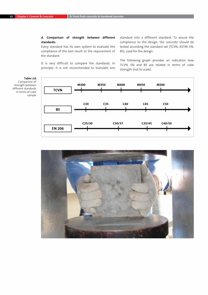
d. Comparison of strength between different standards:Every standard has its own system to evaluate the compliance of the test result to the requirement of the standard.
It is very difficult to compare the standards. In principle, it is not recommended to translate one
standard into a different standard. To assure the compliance to the design, the concrete should be tested according the standard set (TCVN, ASTM, EN, BS), used for the design.
The following graph provides an indication how TCVN, EN and BS are related in terms of cube strength (not to scale).
C25/30 C30/37 C35/45 C40/50EN 206
C30 C35 C40 C45 C50
BS
TCVNM300 M350 M400 M450 M500
Chapter I: Cement & Concrete B. From fresh concrete to hardened concrete
Table I.10 Comparison of
strength between different standards
in terms of cube sample
33
4. Special characteristicsa. Concrete density The density of both fresh and hardened concrete is of interest to the engineers for different reasons including structural design and impact on compressive strength.
By choosing suitable aggregates and mix design, the density of concrete can be increased significantly (heavy concrete) or reduced (light-weight concrete).
For fresh concrete:The density plays an important role in controlling concrete yield (compared to the mix design) at readymix batching plant. Typical readymix concrete density varies from 2200 – 2500kg/m3 (TCXDVN 374:2006), depending on the aggregate type and mix design.
Based on the density of compacted fresh concrete, plant operators are able to check if the mix design is over- or under yielding: this means that the mix design gives more or less than 1m3 concrete after compaction. Fresh concrete density test method complies with ASTM C138; EN 12350 – 6; TCVN 3108:1993.
For hardened concrete:Before testing the compressive strength, the density of concrete samples (cube, cylinder) should be checked and compared with the mix design to confirm the sampling, compaction, presence of entrained air.
Example: A mix design shows that the density of concrete is 2450 kg/m3; however, the hardened concrete sample only measures 2370 kg/m3 .The strength of this sample will be much lower than the design strength. Hardened concrete density is determined either by simple dimensional checks, followed by weighing and calculation or by weight in air/water buoyancy methods (comply with EN 12390-7).
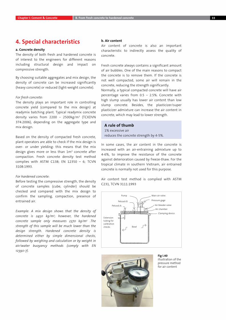
b. Air contentAir content of concrete is also an important characteristic to indirectly assess the quality of concrete.
Fresh concrete always contains a significant amount of air bubbles. One of the main reasons to compact the concrete is to remove them. If the concrete is not well compacted, some air will remain in the concrete, reducing the strength significantly.Normally, a typical compacted concrete will have air percentage varies from 0.5 – 2.5%. Concrete with high slump usually has lower air content than low slump concrete. Besides, the plasticizer/super plasticizer admixture can increase the air content in concrete, which may lead to lower strength.
In some cases, the air content in the concrete is increased with an air-entraining admixture up to 4-6%, to improve the resistance of the concrete against deterioration caused by freeze-thaw. For the tropical climate in southern Vietnam, air entrained concrete is normally not used for this purpose.
Air content test method is complied with ASTM C231, TCVN 3111:1993
Fig I.40illustration of the pressure method for air content
A rule of thumb1% excessive air reduces the concrete strength by 4-5%.
Chapter I: Cement & Concrete B. From fresh concrete to hardened concrete
Extension tubing for calibration checks
Clamping device
Bowl
Air chamber
Air bleeder valve
Pressure gage
Main air valvePump
Petcock B
Petcock A
34
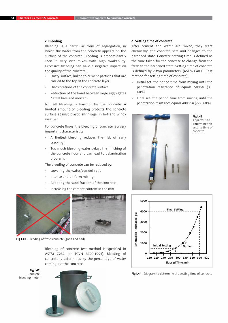
c. BleedingBleeding is a particular form of segregation, in which the water from the concrete appears on the surface of the concrete. Bleeding is predominantly seen in very wet mixes with high workability. Excessive bleeding can have a negative impact on the quality of the concrete:• Dusty surface, linked to cement particles that are
carried to the top of the concrete layer
• Discolorations of the concrete surface
• Reduction of the bond between large aggregates / steel bars and mortar.
Not all bleeding is harmful for the concrete. A limited amount of bleeding protects the concrete surface against plastic shrinkage, in hot and windy weather.
For concrete floors, the bleeding of concrete is a very important characteristic:
• A limited bleeding reduces the risk of early cracking
• Too much bleeding water delays the finishing of the concrete floor and can lead to delamination problems
The bleeding of concrete can be reduced by:
• Lowering the water/cement ratio
• Intense and uniform mixing
• Adapting the sand fraction of the concrete
• Increasing the cement content in the mix
Bleeding of concrete test method is specified in ASTM C232 (or TCVN 3109:1993). Bleeding of concrete is determined by the percentage of water coming out the concrete.
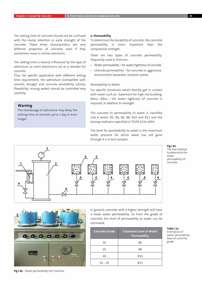
d. Setting time of concreteAfter cement and water are mixed, they react chemically, the concrete sets and changes to the hardened state. Concrete setting time is defined as the time taken for the concrete to change from the fresh to the hardened state. Setting time of concrete is defined by 2 two parameters: (ASTM C403 – Test method for setting time of concrete):
• Initial set: the period time from mixing until the penetration resistance of equals 500psi (3.5 MPa).
• Final set: the period time from mixing until the penetration resistance equals 4000psi (27.6 MPa).
Fig I.42Concrete
bleeding meter
Fig I.43Apparatus to determine the setting time of concrete
Fig I.44 - Diagram to determine the setting time of concrete
Fig I.41 - Bleeding of fresh concrete (good and bad)
0
1000
2000
3000
4000
5000
180 210 240 270 300 330 360 390 420
Pene
trat
ion
Resi
stan
ce, p
si
Elapsed Time, min
Final Setting
Initial Setting Outlier
Chapter I: Cement & Concrete B. From fresh concrete to hardened concrete
35
The setting time of concrete should not be confused with the slump retention or early strength of the concrete. These three characteristics are very different properties of concrete, even if they sometimes move in similar directions.
The setting time is heavily influenced by the type of admixture, as some plasticizers act as a retarder for concrete.Thus, for specific application with different setting time requirement, the admixture (compatible with cement, dosage) and concrete workability (slump, flowability, mixing water) should be controlled very carefully.
e. PermeabilityTo determine the durability of concrete, the concrete permeability is more important than the compressive strength.
There are two types of concrete permeability, frequently used in Vietnam:
• Water permeability – for water-tightness of concrete
• Chloride permeability – for concrete in aggressive environment (seawater, brackish water)
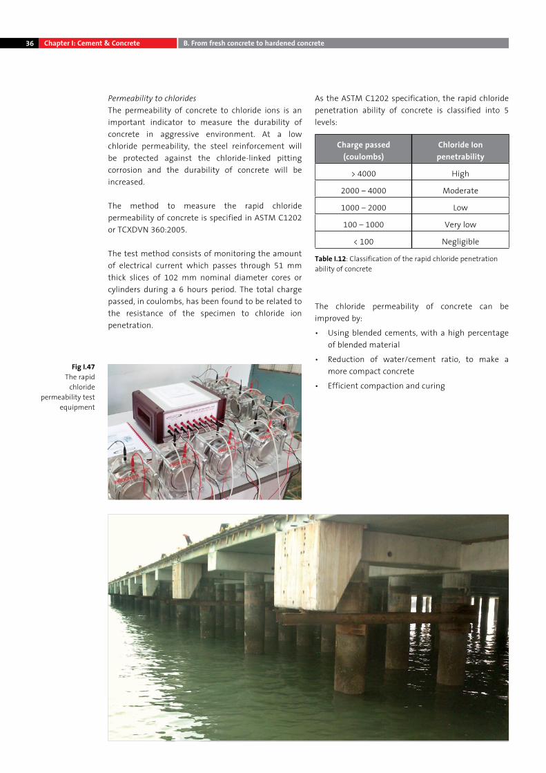
Permeability to Water:
For specific structures which directly get in contact with water such as : basement for high rise building, dams, dikes…, the water tightness of concrete is required, in addition to strength.
The concrete to permeability to water is classified into 6 levels: B2, B4, B6, B8, B10 and B12 and the testing method is specified in TCVN 3116:1993.
The level for permeability to water is the maximum water pressure for which water has not gone through 4 in 6 test samples.
In general, concrete with a higher strength will have a lower water permeability. So from the grade of concrete, the level of permeability to water can be estimated.
Concrete Grade Estimated Level of Water Permeability
30 B6
35 B8
40 B10
45 - 50 B12
1
3
2
4
6 5
4 4 4 4 4 4
4
WarningThe overdosage of admixture may delay the setting time of concrete up to 1 day or even longer.
Fig I.45The test method to determine the water permeability of concrete
Table I.11Estimation of water permeability base on concrete grade
Chapter I: Cement & Concrete B. From fresh concrete to hardened concrete
Fig I.46 - Water permeability test machine
36
Permeability to chlorides The permeability of concrete to chloride ions is an important indicator to measure the durability of concrete in aggressive environment. At a low chloride permeability, the steel reinforcement will be protected against the chloride-linked pitting corrosion and the durability of concrete will be increased.
The method to measure the rapid chloride permeability of concrete is specified in ASTM C1202 or TCXDVN 360:2005.
The test method consists of monitoring the amount of electrical current which passes through 51 mm thick slices of 102 mm nominal diameter cores or cylinders during a 6 hours period. The total charge passed, in coulombs, has been found to be related to the resistance of the specimen to chloride ion penetration.
As the ASTM C1202 specification, the rapid chloride penetration ability of concrete is classified into 5 levels:
Charge passed (coulombs)
Chloride Ion penetrability
> 4000 High
2000 – 4000 Moderate
1000 – 2000 Low
100 – 1000 Very low
< 100 Negligible
The chloride permeability of concrete can be improved by:
• Using blended cements, with a high percentage of blended material
• Reduction of water/cement ratio, to make a more compact concrete
• Efficient compaction and curing
Fig I.47The rapid
chloride permeability test
equipment
Table I.12: Classification of the rapid chloride penetration ability of concrete
Chapter I: Cement & Concrete B. From fresh concrete to hardened concrete
37
5. Production and Transport Dosage of the componentsThe production of concrete is closely linked to the technology and equipment used. The task of dosage is to dispense the components of the concrete mix – aggregate, cement, additions, mixing water, admixtures – in controlled amounts, to produce the specified mix proportions with great accuracy. Two systems are used, dosage by volume and dosage by mass. Dosage by mass gives more accurate results. Every batching plant must establish sequencing for adding the material through systematic pretests. Sequencing is critical for:
• The dispersion • The mixing effect • The optimal effect of admixtures • Plant efficiency • Mechanical wear
Mixing the componentsThe mixer must blend the separate components into a homogeneous mix. The mixer must also satisfy the following requirements and tasks:
• High mixing intensity
• Short mixing duration
• Dispersion of the cement and the additions
• Optimal coating of the aggregates with fines mortar (fines paste)
• Fast discharging
• Low wear
At ready-mix plants the paddle mixer is the most common type, used discontinuously for mixing single batches. Each type of mixer requires a minimum batch size, below which the quality of the fresh concrete is reduced.
Mixing durationThe duration of mixing depends on the type of mixer (drum or paddle mixer). Mixing duration should be determined by testing.
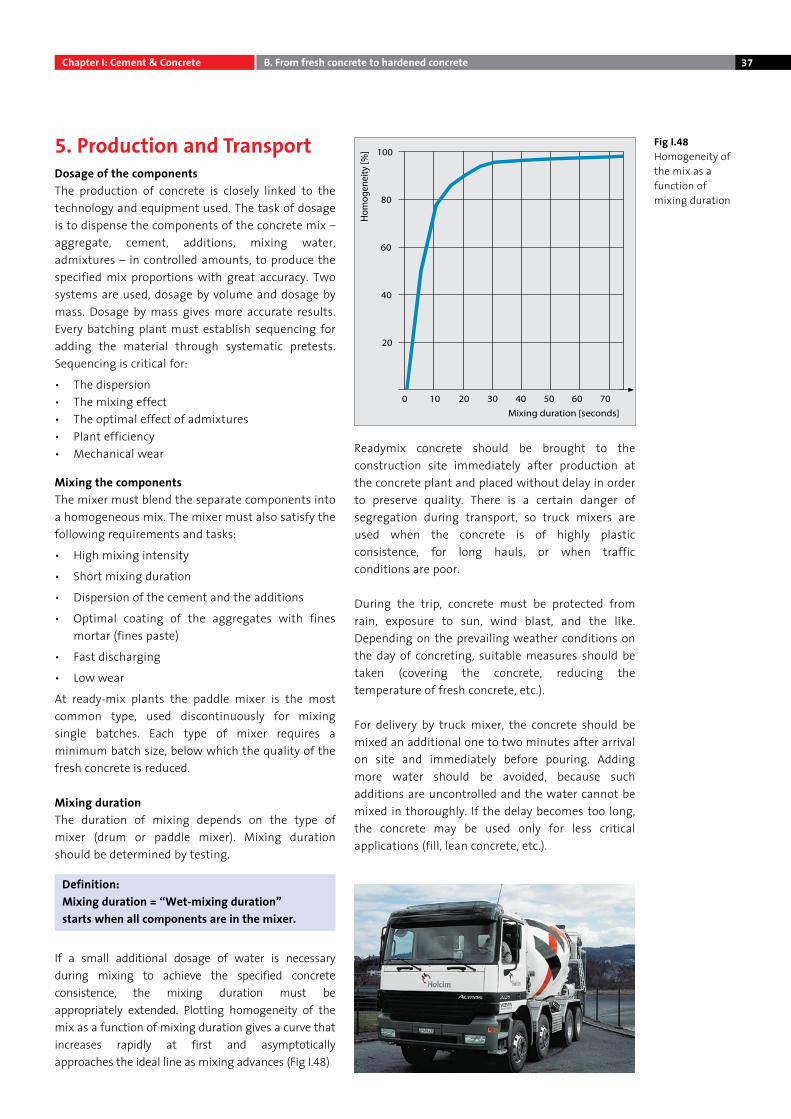
If a small additional dosage of water is necessary during mixing to achieve the specified concrete consistence, the mixing duration must be appropriately extended. Plotting homogeneity of the mix as a function of mixing duration gives a curve that increases rapidly at first and asymptotically approaches the ideal line as mixing advances (Fig I.48)
Readymix concrete should be brought to the construction site immediately after production at the concrete plant and placed without delay in order to preserve quality. There is a certain danger of segregation during transport, so truck mixers are used when the concrete is of highly plastic consistence, for long hauls, or when traffic conditions are poor.
During the trip, concrete must be protected from rain, exposure to sun, wind blast, and the like. Depending on the prevailing weather conditions on the day of concreting, suitable measures should be taken (covering the concrete, reducing the temperature of fresh concrete, etc.).
For delivery by truck mixer, the concrete should be mixed an additional one to two minutes after arrival on site and immediately before pouring. Adding more water should be avoided, because such additions are uncontrolled and the water cannot be mixed in thoroughly. If the delay becomes too long, the concrete may be used only for less critical applications (fill, lean concrete, etc.).
Fig I.48 Homogeneity of the mix as a function of mixing duration
Chapter I: Cement & Concrete B. From fresh concrete to hardened concrete
Definition: Mixing duration = “Wet-mixing duration” starts when all components are in the mixer.
38
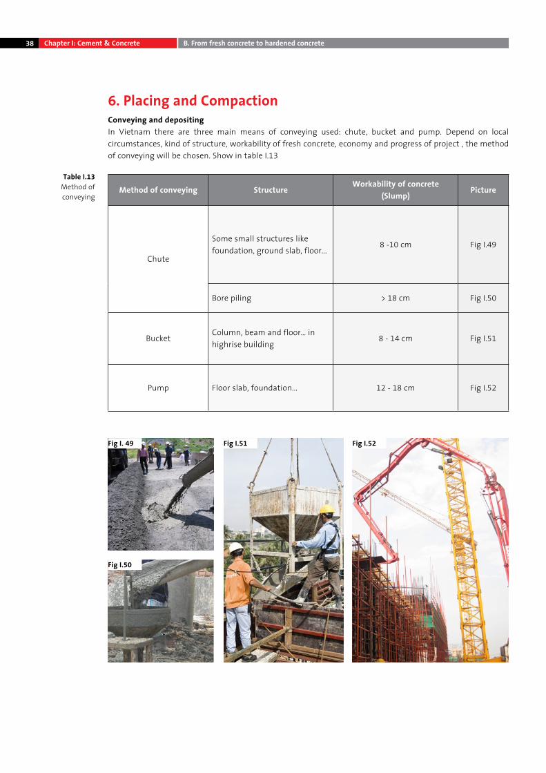
6. Placing and CompactionConveying and depositingIn Vietnam there are three main means of conveying used: chute, bucket and pump. Depend on local circumstances, kind of structure, workability of fresh concrete, economy and progress of project , the method of conveying will be chosen. Show in table I.13
Method of conveying StructureWorkability of concrete
(Slump)Picture
Chute
Some small structures like foundation, ground slab, floor...
8 -10 cm Fig I.49
Bore piling > 18 cm Fig I.50
BucketColumn, beam and floor… in highrise building
8 - 14 cm Fig I.51
Pump Floor slab, foundation... 12 - 18 cm Fig I.52
Fig I. 49
Fig I.50
Table I.13 Method of conveying
Fig I.51 Fig I.52
Chapter I: Cement & Concrete B. From fresh concrete to hardened concrete
39
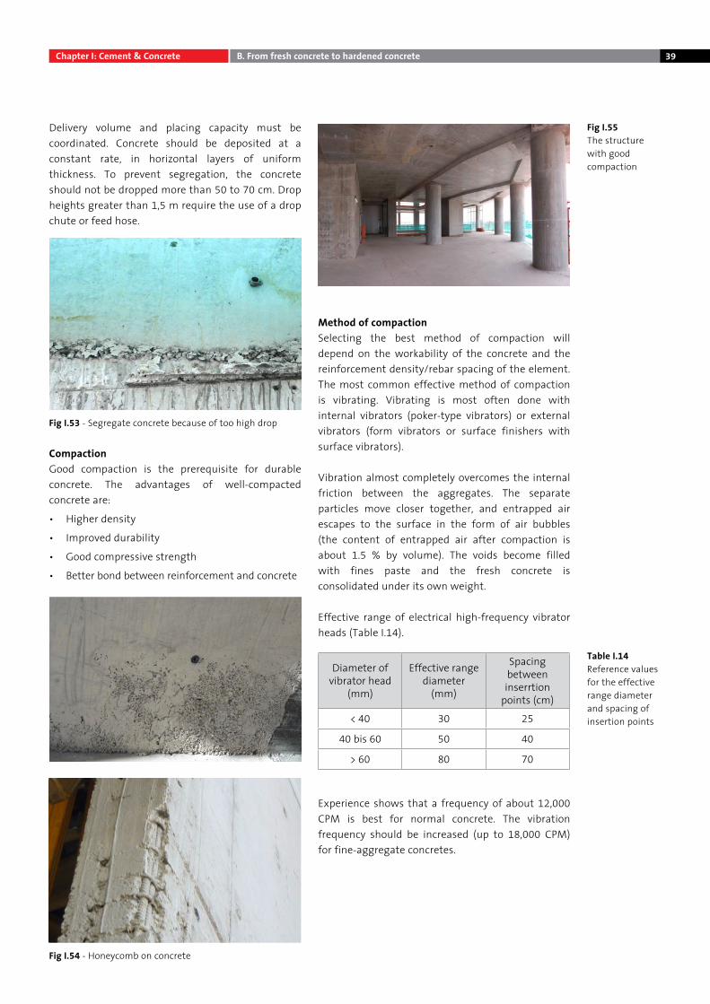
Delivery volume and placing capacity must be coordinated. Concrete should be deposited at a constant rate, in horizontal layers of uniform thickness. To prevent segregation, the concrete should not be dropped more than 50 to 70 cm. Drop heights greater than 1,5 m require the use of a drop chute or feed hose.
CompactionGood compaction is the prerequisite for durable concrete. The advantages of well-compacted concrete are:
• Higher density
• Improved durability
• Good compressive strength
• Better bond between reinforcement and concrete
Method of compactionSelecting the best method of compaction will depend on the workability of the concrete and the reinforcement density/rebar spacing of the element. The most common effective method of compaction is vibrating. Vibrating is most often done with internal vibrators (poker-type vibrators) or external vibrators (form vibrators or surface finishers with surface vibrators).
Vibration almost completely overcomes the internal friction between the aggregates. The separate particles move closer together, and entrapped air escapes to the surface in the form of air bubbles (the content of entrapped air after compaction is about 1.5 % by volume). The voids become filled with fines paste and the fresh concrete is consolidated under its own weight.
Effective range of electrical high-frequency vibrator heads (Table I.14).
Experience shows that a frequency of about 12,000 CPM is best for normal concrete. The vibration frequency should be increased (up to 18,000 CPM) for fine-aggregate concretes.
Fig I.53 - Segregate concrete because of too high drop
Fig I.54 - Honeycomb on concrete
Fig I.55The structure with good compaction
Table I.14 Reference values for the effective range diameter and spacing of insertion points
Diameter of vibrator head
(mm)
Effective range diameter
(mm)
Spacing between inserrtion
points (cm)
< 40 30 25
40 bis 60 50 40
> 60 80 70
Chapter I: Cement & Concrete B. From fresh concrete to hardened concrete
40
Rules for good compaction • The vibrator head should be quickly immersed in
the concrete, held briefly at the lowest point and slowly extracted. The concrete surface must close behind. If the surface no longer closes, either the consistence is too stiff, the concrete has already begun to set, or the duration of vibration has been insufficient. Spacing between the insertion points should be uniform.
• The vibrator head should not be used to distribute the concrete.
• Vibration should be stopped when a thin film of fine mortar forms on the surface and larger air bubbles surface only occasionally.
• The insertion points should be spaced close enough that the effective range diameters of the vibrator overlap.
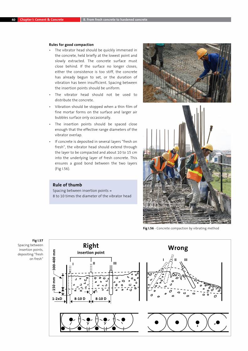
• If concrete is deposited in several layers “fresh on fresh“, the vibrator head should extend through the layer to be compacted and about 10 to 15 cm into the underlying layer of fresh concrete. This ensures a good bond between the two layers (Fig I.56).
Rule of thumb Spacing between insertion points = 8 to 10 times the diameter of the vibrator head
Fig I.57Spacing between insertion points,
depositing “fresh on fresh“
Fig I.56 - Concrete compaction by vibrating method
Rightinsertion point
Wrong
150
mm
1-2xD 8-10 D
II
IIII
IIIIII
8-10 D
300-
400
mm
Chapter I: Cement & Concrete B. From fresh concrete to hardened concrete
41
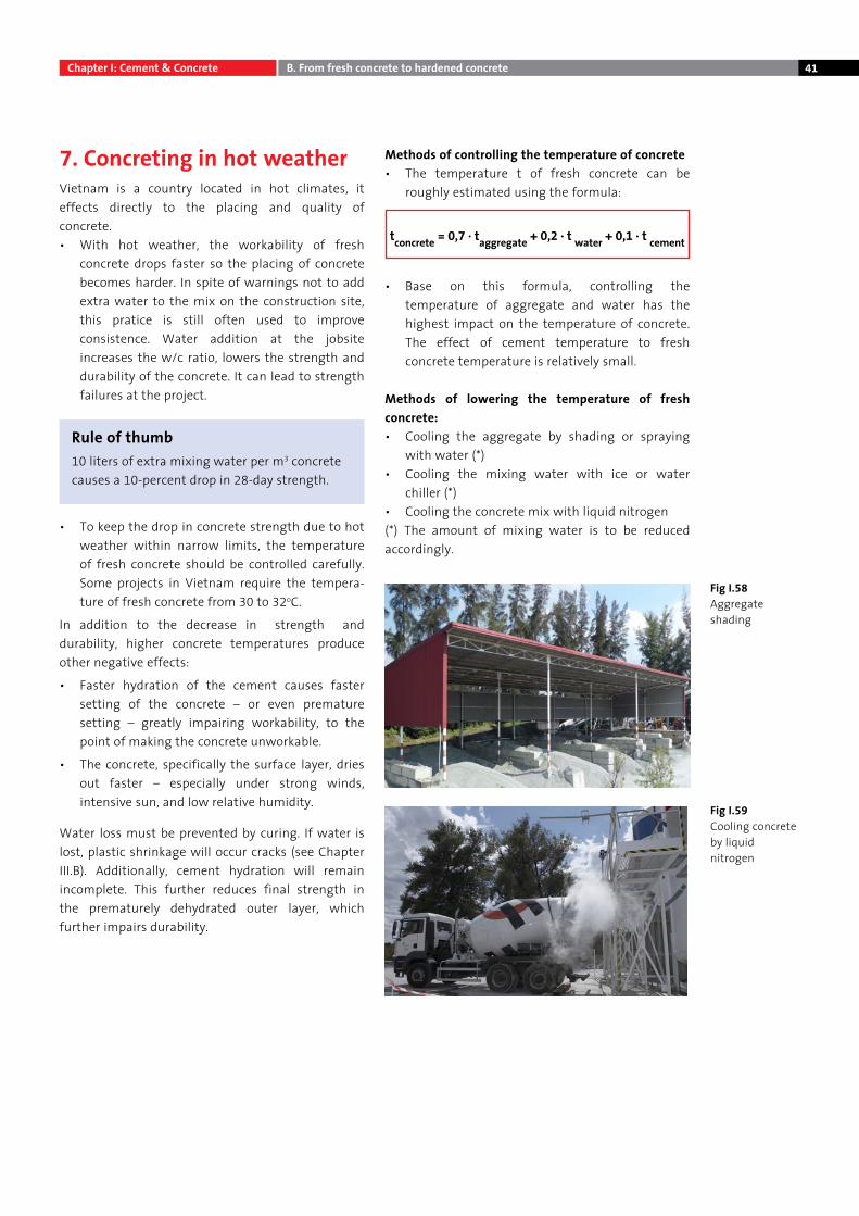
Fig I.58Aggregate shading
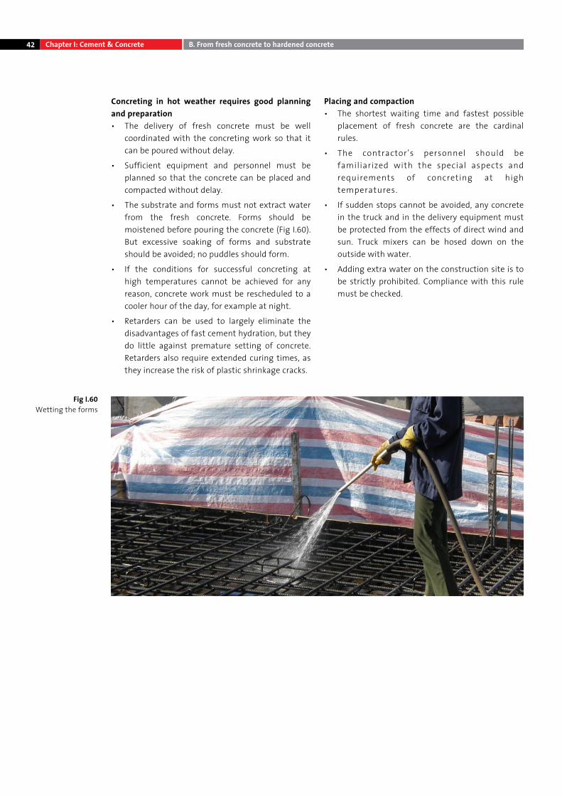
Fig I.59Cooling concrete by liquid nitrogen
7. Concreting in hot weather Vietnam is a country located in hot climates, it effects directly to the placing and quality of concrete. • With hot weather, the workability of fresh
concrete drops faster so the placing of concrete becomes harder. In spite of warnings not to add extra water to the mix on the construction site, this pratice is still often used to improve consistence. Water addition at the jobsite increases the w/c ratio, lowers the strength and durability of the concrete. It can lead to strength failures at the project.
• To keep the drop in concrete strength due to hot weather within narrow limits, the temperature of fresh concrete should be controlled carefully. Some projects in Vietnam require the tempera-ture of fresh concrete from 30 to 32oC.
In addition to the decrease in strength and durability, higher concrete temperatures produce other negative effects:
• Faster hydration of the cement causes faster setting of the concrete – or even premature setting – greatly impairing workability, to the point of making the concrete unworkable.
• The concrete, specifically the surface layer, dries out faster – especially under strong winds, intensive sun, and low relative humidity.
Water loss must be prevented by curing. If water is lost, plastic shrinkage will occur cracks (see Chapter III.B). Additionally, cement hydration will remain incomplete. This further reduces final strength in the prematurely dehydrated outer layer, which further impairs durability.
Methods of controlling the temperature of concrete• The temperature t of fresh concrete can be
roughly estimated using the formula:
• Base on this formula, controlling the temperature of aggregate and water has the highest impact on the temperature of concrete. The effect of cement temperature to fresh concrete temperature is relatively small.
Methods of lowering the temperature of fresh concrete: • Cooling the aggregate by shading or spraying
with water (*) • Cooling the mixing water with ice or water
chiller (*) • Cooling the concrete mix with liquid nitrogen(*) The amount of mixing water is to be reduced accordingly.
Rule of thumb10 liters of extra mixing water per m3 concrete causes a 10-percent drop in 28-day strength.
tconcrete = 0,7 · taggregate + 0,2 · t water + 0,1 · t cement
Chapter I: Cement & Concrete B. From fresh concrete to hardened concrete
42
Concreting in hot weather requires good planning and preparation • The delivery of fresh concrete must be well
coordinated with the concreting work so that it can be poured without delay.
• Sufficient equipment and personnel must be planned so that the concrete can be placed and compacted without delay.
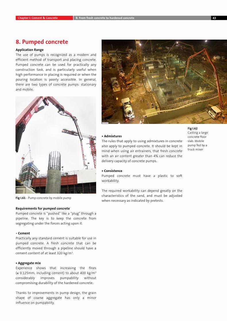
• The substrate and forms must not extract water from the fresh concrete. Forms should be moistened before pouring the concrete (Fig I.60). But excessive soaking of forms and substrate should be avoided; no puddles should form.
• If the conditions for successful concreting at high temperatures cannot be achieved for any reason, concrete work must be rescheduled to a cooler hour of the day, for example at night.
• Retarders can be used to largely eliminate the disadvantages of fast cement hydration, but they do little against premature setting of concrete. Retarders also require extended curing times, as they increase the risk of plastic shrinkage cracks.
Placing and compaction • The shortest waiting time and fastest possible
placement of fresh concrete are the cardinal rules.
• The contractor’s personnel should be familiarized with the special aspects and requirements of concreting at high temperatures.
• If sudden stops cannot be avoided, any concrete in the truck and in the delivery equipment must be protected from the effects of direct wind and sun. Truck mixers can be hosed down on the outside with water.
• Adding extra water on the construction site is to be strictly prohibited. Compliance with this rule must be checked.
Fig I.60 Wetting the forms
Chapter I: Cement & Concrete B. From fresh concrete to hardened concrete
43
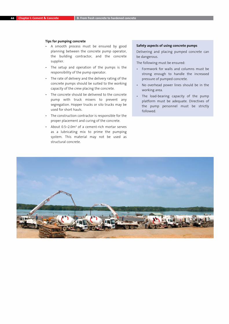
8. Pumped concreteApplication RangeThe use of pumps is recognized as a modern and efficient method of transport and placing concrete. Pumped concrete can be used for practically any construction task, and is particularly useful when high performance in placing is required or when the pouring location is poorly accessible. In general, there are two types of concrete pumps: stationary and mobile.
Requirements for pumped concretePumped concrete is “pushed“ like a “plug“ through a pipeline. The key is to keep the concrete from segregating under the forces acting upon it.
• Cement Practically any standard cement is suitable for use in pumped concrete. A fresh concrete that can be efficiently moved through a pipeline should have a cement content of at least 320 kg/m3.
• Aggregate mix Experience shows that increasing the fines (≤ 0.125mm, including cement) to about 400 kg/m3 considerably improves pumpability without compromising durability of the hardened concrete.
Thanks to improvements in pump design, the grain shape of coarse aggregate has only a minor influence on pumpability.
• AdmixturesThe rules that apply to using admixtures in concrete also apply to pumped concrete. It should be kept in mind when using air entrainers, that fresh concrete with an air content greater than 4% can reduce the delivery capacity of concrete pumps.
• Consistence Pumped concrete must have a plastic to soft workability.
The required workability can depend greatly on the characteristics of the sand, and must be adjusted when necessary as indicated by pretests.
Fig I.62 Casting a large concrete floor slab. Mobile pump fed by a truck mixer
Fig I.61 - Pump concrete by mobile pump
Chapter I: Cement & Concrete B. From fresh concrete to hardened concrete
44
Tips for pumping concrete • A smooth process must be ensured by good
planning between the concrete pump operator, the building contractor, and the concrete supplier.
• The setup and operation of the pumps is the responsibility of the pump operator.
• The rate of delivery and the delivery rating of the concrete pumps should be suited to the working capacity of the crew placing the concrete.
• The concrete should be delivered to the concrete pump with truck mixers to prevent any segregation. Hopper trucks or silo trucks may be used for short hauls.
• The construction contractor is responsible for the proper placement and curing of the concrete.
• About 0.5–2.0m3 of a cement-rich mortar serves as a lubricating mix to prime the pumping system. This material may not be used as structural concrete.
Safety aspects of using concrete pumps
Delivering and placing pumped concrete can be dangerous.
The following must be ensured:
• Formwork for walls and columns must be strong enough to handle the increased pressure of pumped concrete.
• No overhead power lines should be in the working area.
• The load-bearing capacity of the pump platform must be adequate. Directives of the pump personnel must be strictly followed.
Chapter I: Cement & Concrete B. From fresh concrete to hardened concrete
45
9. Curing Purpose and objectivesThe purpose of curing is to protect concrete from water loss and harmful influences during the early hardening period. Compressive strength alone does not guarantee durability; the concrete must also be dense. Especially in the surface layer, hardened cement paste with high density and low-as-possible permeability is very important.
This gives better resistance to carbonation and other types of attack. Curing includes all the measures taken to protect freshly placed, young concrete while it develops adequate strength. The chief objectives of curing is to protect the concrete from:
• Evaporation due to wind, sun, dry cold
• Extreme temperatures (cold or heat) and rapid temperature change
• Heavy rain
• Early influences of foreign substances (oil etc.)
Premature dryingProtection against premature moisture loss is especially important. Protective measures must be taken immediately after concrete is placed.
The consequences of premature water loss in the surface layers are: • Heavy plastic-shrinkage cracking (see Chapter III)
• Low strength
• Tendency to surface dusting
• Lower density and durability
• Faster corrosion of steel reinforcement
• Lower abrasion resistance
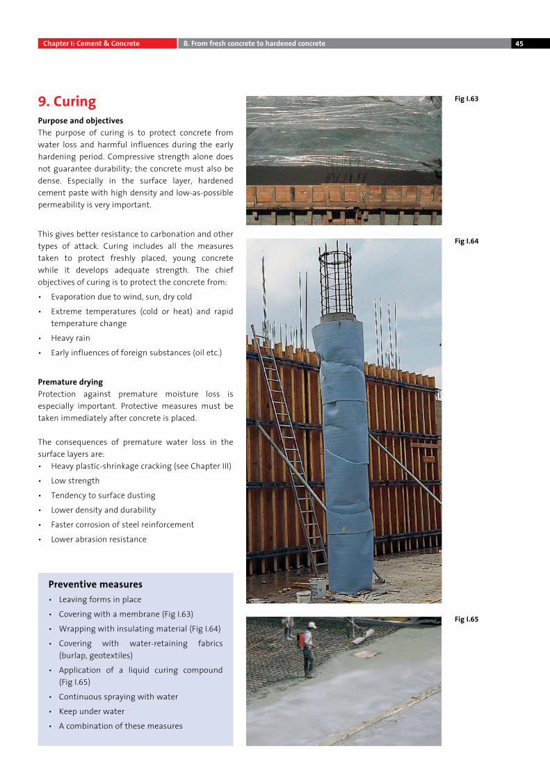
Preventive measures• Leaving forms in place
• Covering with a membrane (Fig I.63)
• Wrapping with insulating material (Fig I.64)
• Covering with water-retaining fabrics (burlap, geotextiles)
• Application of a liquid curing compound (Fig I.65)
• Continuous spraying with water
• Keep under water
• A combination of these measures
Fig I.65
Fig I.63
Fig I.64
Chapter I: Cement & Concrete B. From fresh concrete to hardened concrete
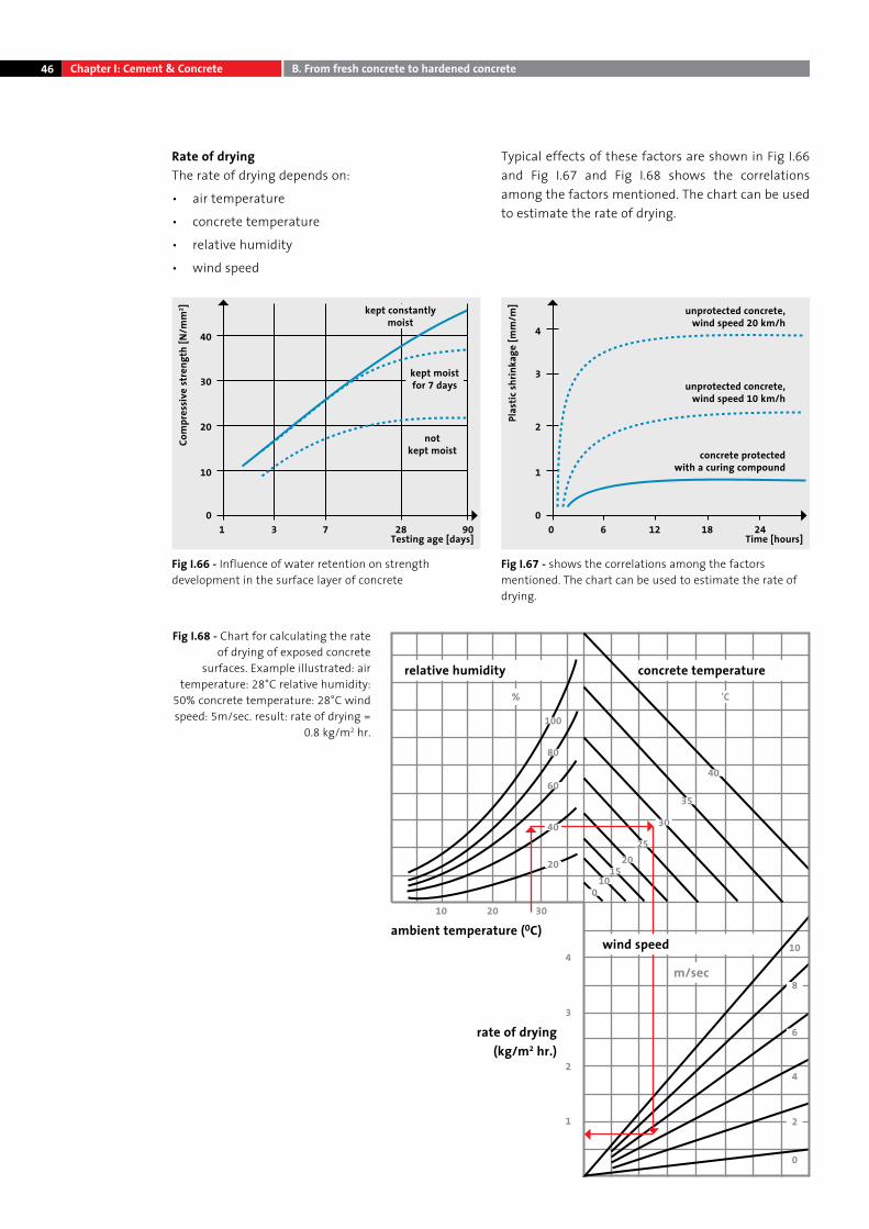
46
Rate of dryingThe rate of drying depends on:
• air temperature
• concrete temperature
• relative humidity
• wind speed
Typical effects of these factors are shown in Fig I.66 and Fig I.67 and Fig I.68 shows the correlations among the factors mentioned. The chart can be used to estimate the rate of drying.
Fig I.66 - Influence of water retention on strength development in the surface layer of concrete
Fig I.67 - shows the correlations among the factors mentioned. The chart can be used to estimate the rate of drying.
Testing age [days]
kept constantlymoist
notkept moist
kept moistfor 7 days
10
10
20
30
40
3 7 28 90
Com
pres
sive
stre
ngth
[N/m
m2 ]
Time [hours]
unprotected concrete,wind speed 20 km/h
unprotected concrete,wind speed 10 km/h
concrete protectedwith a curing compound
00
1
2
3
4
6 12 18 24
Plas
tic sh
rinka
ge [m
m/m
]
Fig I.68 - Chart for calculating the rate of drying of exposed concrete
surfaces. Example illustrated: air temperature: 28°C relative humidity:
50% concrete temperature: 28°C wind speed: 5m/sec. result: rate of drying =
0.8 kg/m2 hr.
relative humidity
ambient temperature (0C)10 20 30
20
0
410
8
6
4
2
0
3
2
1
1015
2025
30
40
'C%
35
40
60
80
100
wind speed
m/sec
rate of drying (kg/m2 hr.)
concrete temperature
Chapter I: Cement & Concrete B. From fresh concrete to hardened concrete
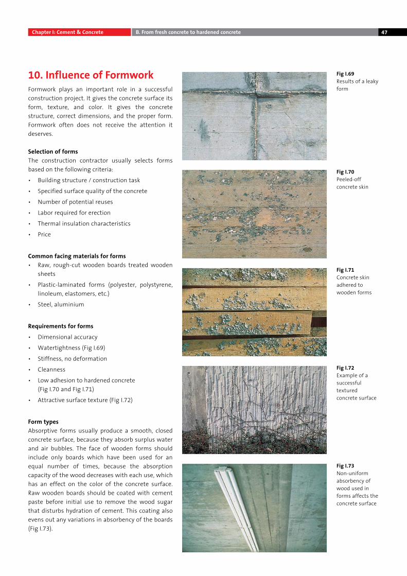
47
10. Influence of FormworkFormwork plays an important role in a successful construction project. It gives the concrete surface its form, texture, and color. It gives the concrete structure, correct dimensions, and the proper form. Formwork often does not receive the attention it deserves.
Selection of formsThe construction contractor usually selects forms based on the following criteria:
• Building structure / construction task
• Specified surface quality of the concrete
• Number of potential reuses
• Labor required for erection
• Thermal insulation characteristics
• Price
Common facing materials for forms • Raw, rough-cut wooden boards treated wooden
sheets
• Plastic-laminated forms (polyester, polystyrene, linoleum, elastomers, etc.)
• Steel, aluminium
Requirements for forms
• Dimensional accuracy
• Watertightness (Fig I.69)
• Stiffness, no deformation
• Cleanness
• Low adhesion to hardened concrete (Fig I.70 and Fig I.71)
• Attractive surface texture (Fig I.72)
Form typesAbsorptive forms usually produce a smooth, closed concrete surface, because they absorb surplus water and air bubbles. The face of wooden forms should include only boards which have been used for an equal number of times, because the absorption capacity of the wood decreases with each use, which has an effect on the color of the concrete surface. Raw wooden boards should be coated with cement paste before initial use to remove the wood sugar that disturbs hydration of cement. This coating also evens out any variations in absorbency of the boards (Fig I.73).
Fig I.72 Example of a successful textured concrete surface
Fig I.73 Non-uniform absorbency of wood used in forms affects the concrete surface
Fig I.71 Concrete skin adhered to wooden forms
Fig I.69 Results of a leaky form
Fig I.70 Peeled-off concrete skin
Chapter I: Cement & Concrete B. From fresh concrete to hardened concrete
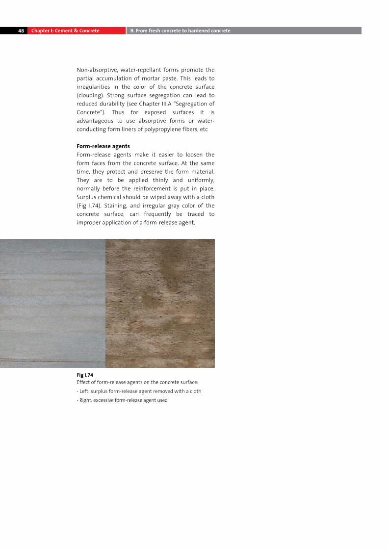
48
Non-absorptive, water-repellant forms promote the partial accumulation of mortar paste. This leads to irregularities in the color of the concrete surface (clouding). Strong surface segregation can lead to reduced durability (see Chapter III.A “Segregation of Concrete“). Thus for exposed surfaces it is advantageous to use absorptive forms or water-conducting form liners of polypropylene fibers, etc
Form-release agentsForm-release agents make it easier to loosen the form faces from the concrete surface. At the same time, they protect and preserve the form material. They are to be applied thinly and uniformly, normally before the reinforcement is put in place. Surplus chemical should be wiped away with a cloth (Fig I.74). Staining, and irregular gray color of the concrete surface, can frequently be traced to improper application of a form-release agent.
Fig I.74 Effect of form-release agents on the concrete surface:
- Left: surplus form-release agent removed with a cloth
- Right: excessive form-release agent used
Chapter I: Cement & Concrete B. From fresh concrete to hardened concrete
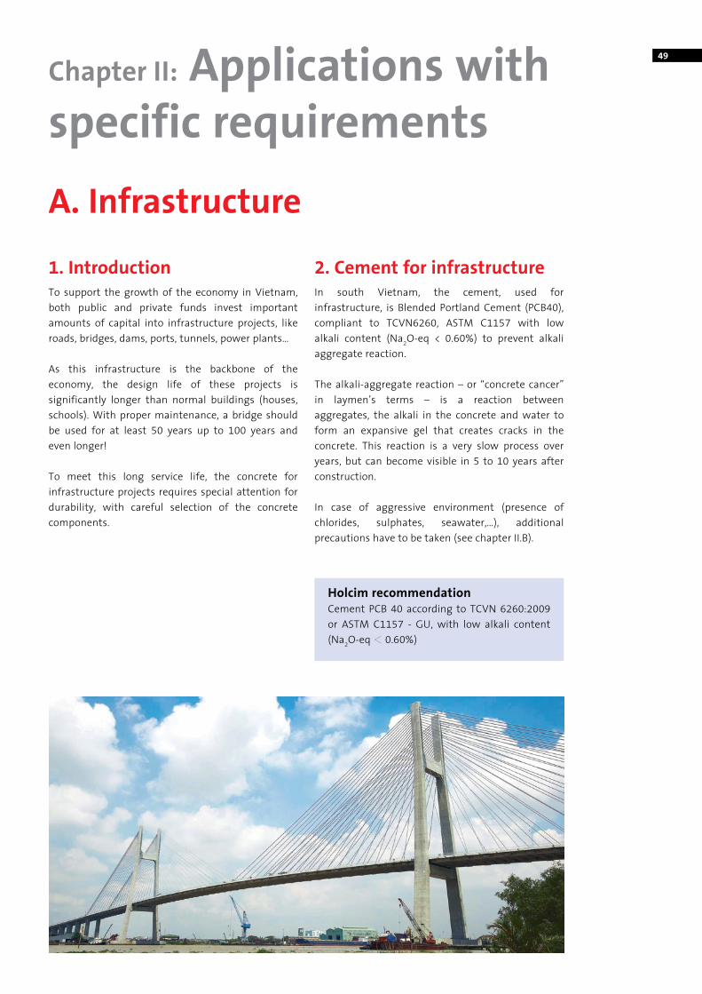
49
A. Infrastructure
Chapter II: Applications with specific requirements
1. IntroductionTo support the growth of the economy in Vietnam, both public and private funds invest important amounts of capital into infrastructure projects, like roads, bridges, dams, ports, tunnels, power plants…
As this infrastructure is the backbone of the economy, the design life of these projects is significantly longer than normal buildings (houses, schools). With proper maintenance, a bridge should be used for at least 50 years up to 100 years and even longer!
To meet this long service life, the concrete for infrastructure projects requires special attention for durability, with careful selection of the concrete components.
2. Cement for infrastructureIn south Vietnam, the cement, used for infrastructure, is Blended Portland Cement (PCB40), compliant to TCVN6260, ASTM C1157 with low alkali content (Na2O-eq < 0.60%) to prevent alkali aggregate reaction.
The alkali-aggregate reaction – or “concrete cancer” in laymen’s terms – is a reaction between aggregates, the alkali in the concrete and water to form an expansive gel that creates cracks in the concrete. This reaction is a very slow process over years, but can become visible in 5 to 10 years after construction.
In case of aggressive environment (presence of chlorides, sulphates, seawater,…), additional precautions have to be taken (see chapter II.B).
Holcim recommendationCement PCB 40 according to TCVN 6260:2009 or ASTM C1157 - GU, with low alkali content (Na2O-eq M 0.60%)
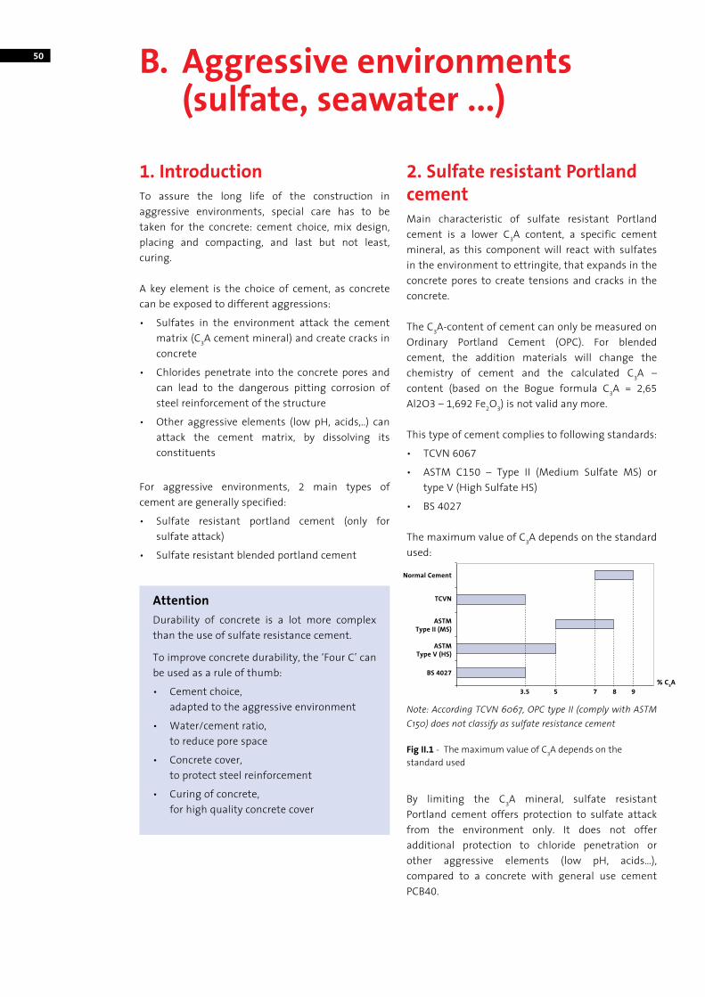
50
1. Introduction To assure the long life of the construction in aggressive environments, special care has to be taken for the concrete: cement choice, mix design, placing and compacting, and last but not least, curing.
A key element is the choice of cement, as concrete can be exposed to different aggressions:
• Sulfates in the environment attack the cement matrix (C3A cement mineral) and create cracks in concrete
• Chlorides penetrate into the concrete pores and can lead to the dangerous pitting corrosion of steel reinforcement of the structure
• Other aggressive elements (low pH, acids,..) can attack the cement matrix, by dissolving its constituents
For aggressive environments, 2 main types of cement are generally specified:
• Sulfate resistant portland cement (only for sulfate attack)
• Sulfate resistant blended portland cement
2. Sulfate resistant Portland cementMain characteristic of sulfate resistant Portland cement is a lower C3A content, a specific cement mineral, as this component will react with sulfates in the environment to ettringite, that expands in the concrete pores to create tensions and cracks in the concrete.
The C3A-content of cement can only be measured on Ordinary Portland Cement (OPC). For blended cement, the addition materials will change the chemistry of cement and the calculated C3A – content (based on the Bogue formula C3A = 2,65 Al2O3 – 1,692 Fe2O3) is not valid any more.
This type of cement complies to following standards:
• TCVN 6067
• ASTM C150 – Type II (Medium Sulfate MS) or type V (High Sulfate HS)
• BS 4027
The maximum value of C3A depends on the standard used:
By limiting the C3A mineral, sulfate resistant Portland cement offers protection to sulfate attack from the environment only. It does not offer additional protection to chloride penetration or other aggressive elements (low pH, acids…), compared to a concrete with general use cement PCB40.
B. Aggressive environments (sulfate, seawater ...)
Note: According TCVN 6067, OPC type II (comply with ASTM C150) does not classify as sulfate resistance cement
Fig II.1 - The maximum value of C3A depends on the standard used
AttentionDurability of concrete is a lot more complex than the use of sulfate resistance cement.
To improve concrete durability, the ‘Four C’ can be used as a rule of thumb:
• Cement choice, adapted to the aggressive environment
• Water/cement ratio, to reduce pore space
• Concrete cover, to protect steel reinforcement
• Curing of concrete, for high quality concrete cover
Normal Cement
TCVN
ASTMType II (MS)
ASTMType V (HS)
BS 4027
3.5 5 7 8 9% C3A
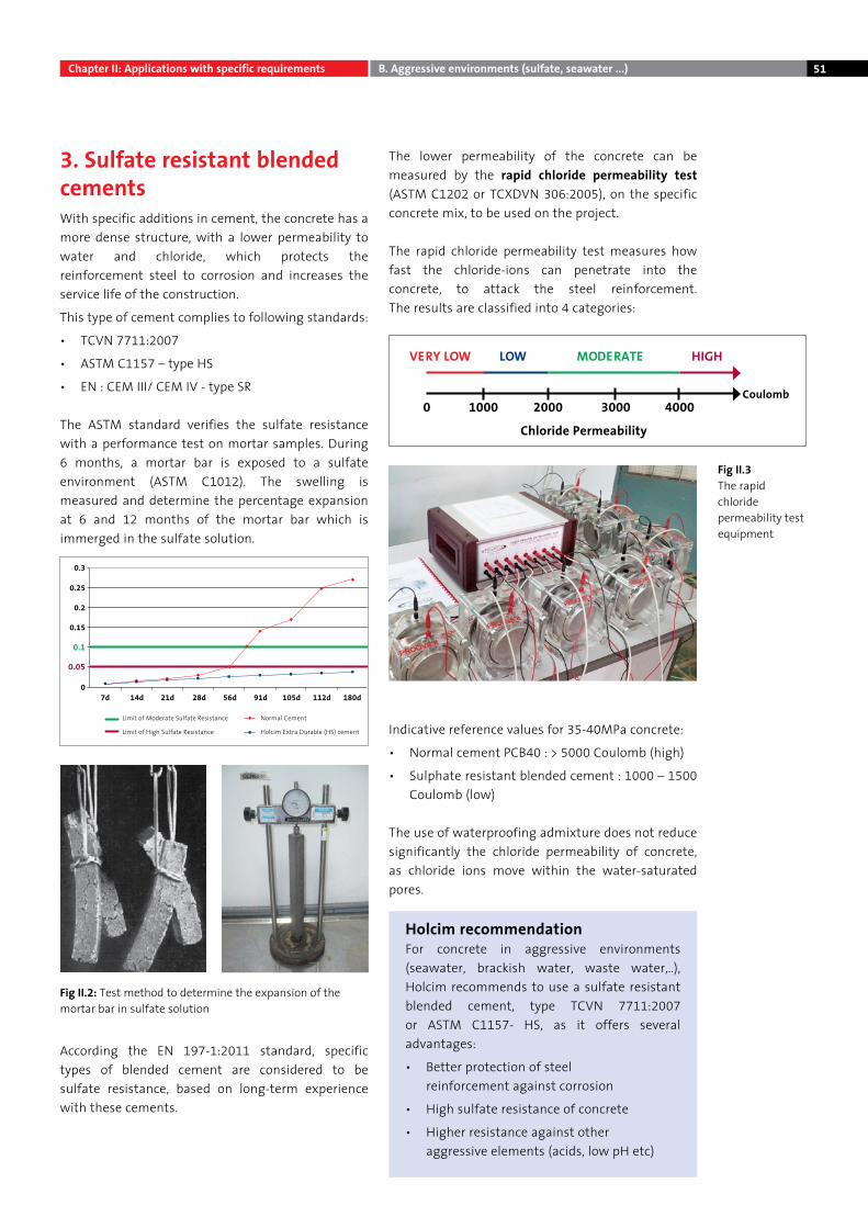
51
3. Sulfate resistant blended cementsWith specific additions in cement, the concrete has a more dense structure, with a lower permeability to water and chloride, which protects the reinforcement steel to corrosion and increases the service life of the construction.
This type of cement complies to following standards:
• TCVN 7711:2007
• ASTM C1157 – type HS
• EN : CEM III/ CEM IV - type SR
The ASTM standard verifies the sulfate resistance with a performance test on mortar samples. During 6 months, a mortar bar is exposed to a sulfate environment (ASTM C1012). The swelling is measured and determine the percentage expansion at 6 and 12 months of the mortar bar which is immerged in the sulfate solution.
According the EN 197-1:2011 standard, specific types of blended cement are considered to be sulfate resistance, based on long-term experience with these cements.
The lower permeability of the concrete can be measured by the rapid chloride permeability test (ASTM C1202 or TCXDVN 306:2005), on the specific concrete mix, to be used on the project.
The rapid chloride permeability test measures how fast the chloride-ions can penetrate into the concrete, to attack the steel reinforcement. The results are classified into 4 categories:
Indicative reference values for 35-40MPa concrete:
• Normal cement PCB40 : > 5000 Coulomb (high)
• Sulphate resistant blended cement : 1000 – 1500 Coulomb (low)
The use of waterproofing admixture does not reduce significantly the chloride permeability of concrete, as chloride ions move within the water-saturated pores.
Holcim recommendationFor concrete in aggressive environments (seawater, brackish water, waste water,..), Holcim recommends to use a sulfate resistant blended cement, type TCVN 7711:2007 or ASTM C1157- HS, as it offers several advantages:
• Better protection of steel reinforcement against corrosion
• High sulfate resistance of concrete
• Higher resistance against other aggressive elements (acids, low pH etc)
Fig II.3The rapid chloride permeability test equipment
Fig II.2: Test method to determine the expansion of the mortar bar in sulfate solution
0.3
0.25
0.2
0.15
07d 14d
Limit of Moderate Sulfate Resistance Normal Cement
Limit of High Sulfate Resistance Holcim Extra Durable (HS) cement
21d 28d 56d 91d 105d 112d 180d
0.1
0.05
Chloride Permeability
VERY LOW LOW MODERATE HIGH
0 1000 2000 3000 4000Coulomb
Chapter II: Applications with specific requirements B. Aggressive environments (sulfate, seawater ...)
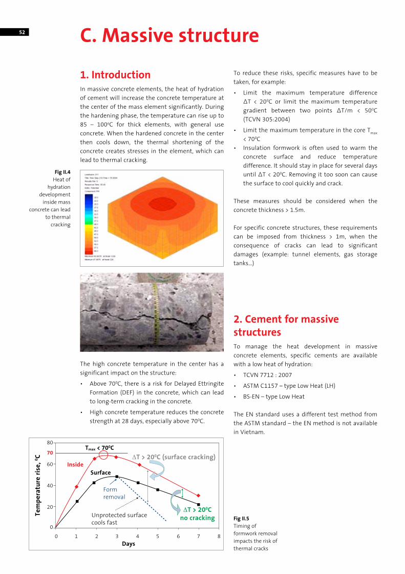
52 C. Massive structure
1. IntroductionIn massive concrete elements, the heat of hydration of cement will increase the concrete temperature at the center of the mass element significantly. During the hardening phase, the temperature can rise up to 85 – 100oC for thick elements, with general use concrete. When the hardened concrete in the center then cools down, the thermal shortening of the concrete creates stresses in the element, which can lead to thermal cracking.
The high concrete temperature in the center has a significant impact on the structure:
• Above 700C, there is a risk for Delayed Ettringite Formation (DEF) in the concrete, which can lead to long-term cracking in the concrete.
• High concrete temperature reduces the concrete strength at 28 days, especially above 700C.
To reduce these risks, specific measures have to be taken, for example:
• Limit the maximum temperature difference∆T < 200C or limit the maximum temperature gradient between two points ∆T/m < 500C (TCVN 305:2004)
• Limit the maximum temperature in the core Tmax < 700C
• Insulation formwork is often used to warm the concrete surface and reduce temperature difference. It should stay in place for several days until ∆T < 200C. Removing it too soon can cause the surface to cool quickly and crack.
These measures should be considered when the concrete thickness > 1.5m.
For specific concrete structures, these requirements can be imposed from thickness > 1m, when the consequence of cracks can lead to significant damages (example: tunnel elements, gas storage tanks…)
2. Cement for massive structuresTo manage the heat development in massive concrete elements, specific cements are available with a low heat of hydration:
• TCVN 7712 : 2007
• ASTM C1157 – type Low Heat (LH)
• BS-EN – type Low Heat
The EN standard uses a different test method from the ASTM standard – the EN method is not available in Vietnam.
Fig II.5Timing of formwork removal impacts the risk of thermal cracks
Unprotected surface cools fast
Formremoval
InsideSurface
Tmax < 700CΔT > 200C (surface cracking)
ΔT > 200Cno cracking
Days
80
70
60
40
20
00 1 2 3 4 5 6 7 8
Tem
pera
ture
rise
, 0 C
Fig II.4Heat of
hydration development
inside mass concrete can lead
to thermal cracking
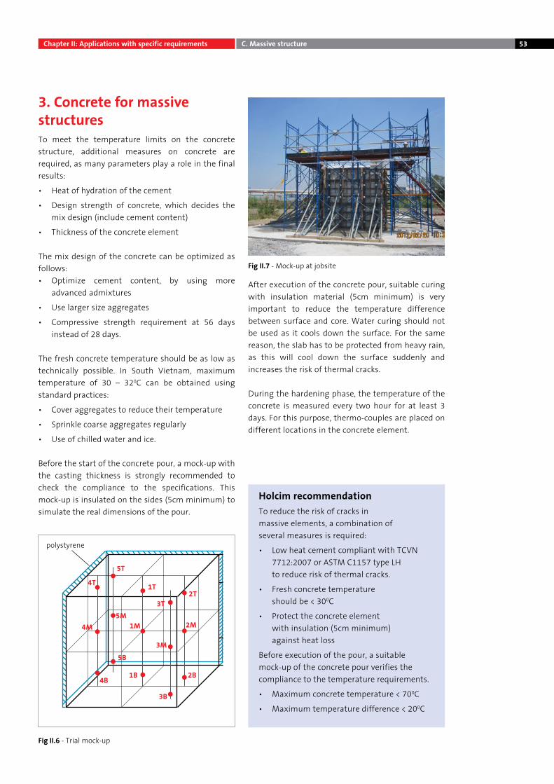
53
3. Concrete for massive structuresTo meet the temperature limits on the concrete structure, additional measures on concrete are required, as many parameters play a role in the final results:
• Heat of hydration of the cement
• Design strength of concrete, which decides the mix design (include cement content)
• Thickness of the concrete element
The mix design of the concrete can be optimized as follows:• Optimize cement content, by using more
advanced admixtures
• Use larger size aggregates
• Compressive strength requirement at 56 days instead of 28 days.
The fresh concrete temperature should be as low as technically possible. In South Vietnam, maximum temperature of 30 – 320C can be obtained using standard practices:
• Cover aggregates to reduce their temperature
• Sprinkle coarse aggregates regularly
• Use of chilled water and ice.
Before the start of the concrete pour, a mock-up with the casting thickness is strongly recommended to check the compliance to the specifications. This mock-up is insulated on the sides (5cm minimum) to simulate the real dimensions of the pour.
After execution of the concrete pour, suitable curing with insulation material (5cm minimum) is very important to reduce the temperature difference between surface and core. Water curing should not be used as it cools down the surface. For the same reason, the slab has to be protected from heavy rain, as this will cool down the surface suddenly and increases the risk of thermal cracks.
During the hardening phase, the temperature of the concrete is measured every two hour for at least 3 days. For this purpose, thermo-couples are placed on different locations in the concrete element.
Holcim recommendationTo reduce the risk of cracks in massive elements, a combination of several measures is required:
• Low heat cement compliant with TCVN 7712:2007 or ASTM C1157 type LH to reduce risk of thermal cracks.
• Fresh concrete temperature should be < 300C
• Protect the concrete element with insulation (5cm minimum) against heat loss
Before execution of the pour, a suitable mock-up of the concrete pour verifies the compliance to the temperature requirements.
• Maximum concrete temperature < 700C
• Maximum temperature difference < 200C
Fig II.7 - Mock-up at jobsite
Fig II.6 - Trial mock-up
4T
5T
1T2T
3T
4M5M
1M 2M
3M5B
4B1B 2B
3B
polystyrene
Chapter II: Applications with specific requirements C. Massive structure
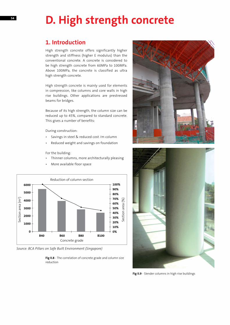
54 D. High strength concrete
1. IntroductionHigh strength concrete offers significantly higher strength and stiffness (higher E modulus) than the conventional concrete. A concrete is considered to be high strength concrete from 60MPa to 100MPa. Above 100MPa, the concrete is classified as ultra high strength concrete.
High strength concrete is mainly used for elements in compression, like columns and core walls in high rise buildings. Other applications are prestressed beams for bridges.
Because of its high strength, the column size can be reduced up to 45%, compared to standard concrete. This gives a number of benefits:
During construction:
• Savings in steel & reduced cost /m column
• Reduced weight and savings on foundation
For the building:• Thinner columns, more architecturally pleasing
• More available floor space
Concrete grade
Source: BCA Pillars on Safe Built Environment (Singapore)
Reduction of column section6000 100%
90%80%70%60%50%40%30%20%10%0%
5000
4000
3000
2000
1000
B40 B60 B80 B1000
Sect
ion
area
(%)
Sect
ion
area
(m2 )
Fig II.8 - The correlation of concrete grade and column size reduction
Fig II.9 - Slender columns in high rise buildings
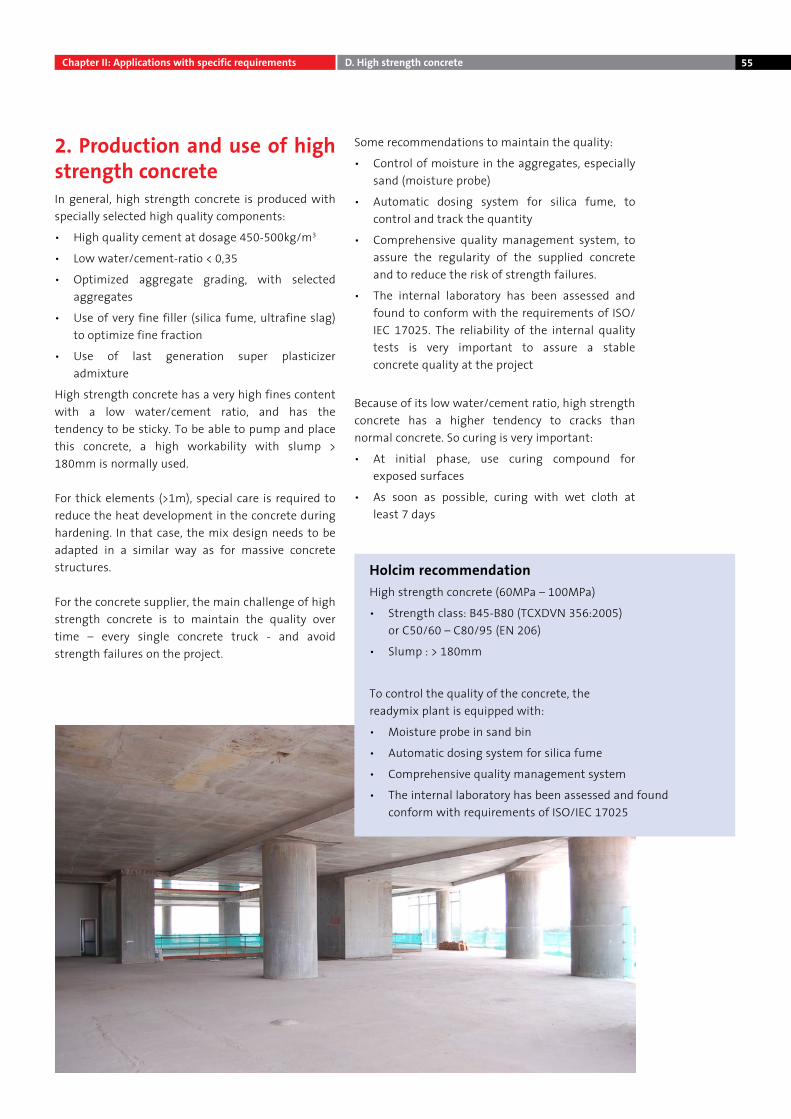
55
2. Production and use of high strength concreteIn general, high strength concrete is produced with specially selected high quality components:
• High quality cement at dosage 450-500kg/m3
• Low water/cement-ratio < 0,35
• Optimized aggregate grading, with selected aggregates
• Use of very fine filler (silica fume, ultrafine slag) to optimize fine fraction
• Use of last generation super plasticizer admixture
High strength concrete has a very high fines content with a low water/cement ratio, and has the tendency to be sticky. To be able to pump and place this concrete, a high workability with slump > 180mm is normally used.
For thick elements (>1m), special care is required to reduce the heat development in the concrete during hardening. In that case, the mix design needs to be adapted in a similar way as for massive concrete structures.
For the concrete supplier, the main challenge of high strength concrete is to maintain the quality over time – every single concrete truck - and avoid strength failures on the project.
Some recommendations to maintain the quality:
• Control of moisture in the aggregates, especially sand (moisture probe)
• Automatic dosing system for silica fume, to control and track the quantity
• Comprehensive quality management system, to assure the regularity of the supplied concrete and to reduce the risk of strength failures.
• The internal laboratory has been assessed and found to conform with the requirements of ISO/IEC 17025. The reliability of the internal quality tests is very important to assure a stable concrete quality at the project
Because of its low water/cement ratio, high strength concrete has a higher tendency to cracks than normal concrete. So curing is very important:
• At initial phase, use curing compound for exposed surfaces
• As soon as possible, curing with wet cloth at least 7 days
Holcim recommendationHigh strength concrete (60MPa – 100MPa)
• Strength class: B45-B80 (TCXDVN 356:2005) or C50/60 – C80/95 (EN 206)
• Slump : > 180mm
To control the quality of the concrete, the readymix plant is equipped with:
• Moisture probe in sand bin
• Automatic dosing system for silica fume
• Comprehensive quality management system
• The internal laboratory has been assessed and found conform with requirements of ISO/IEC 17025
Chapter II: Applications with specific requirements D. High strength concrete
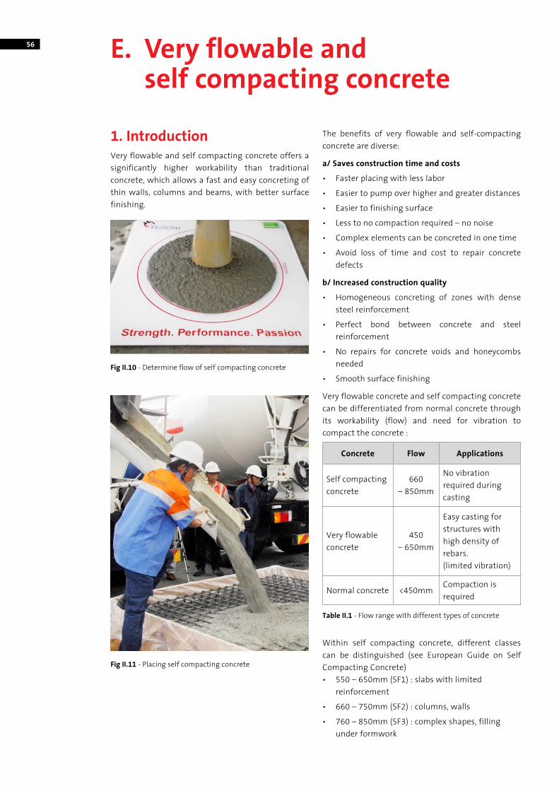
56 E. Very flowable and self compacting concrete
1. IntroductionVery flowable and self compacting concrete offers a significantly higher workability than traditional concrete, which allows a fast and easy concreting of thin walls, columns and beams, with better surface finishing.
The benefits of very flowable and self-compacting concrete are diverse:
a/ Saves construction time and costs
• Faster placing with less labor
• Easier to pump over higher and greater distances
• Easier to finishing surface
• Less to no compaction required – no noise
• Complex elements can be concreted in one time
• Avoid loss of time and cost to repair concrete defects
b/ Increased construction quality
• Homogeneous concreting of zones with dense steel reinforcement
• Perfect bond between concrete and steel reinforcement
• No repairs for concrete voids and honeycombs needed
• Smooth surface finishing
Very flowable concrete and self compacting concrete can be differentiated from normal concrete through its workability (flow) and need for vibration to compact the concrete :
Concrete Flow Applications
Self compacting concrete
660 – 850mm
No vibration required during casting
Very flowable concrete
450 – 650mm
Easy casting for structures with high density of rebars.(limited vibration)
Normal concrete <450mmCompaction is required
Within self compacting concrete, different classes can be distinguished (see European Guide on Self Compacting Concrete)• 550 – 650mm (SF1) : slabs with limited
reinforcement
• 660 – 750mm (SF2) : columns, walls
• 760 – 850mm (SF3) : complex shapes, filling under formwork
Fig II.11 - Placing self compacting concrete
Table II.1 - Flow range with different types of concrete
Fig II.10 - Determine flow of self compacting concrete
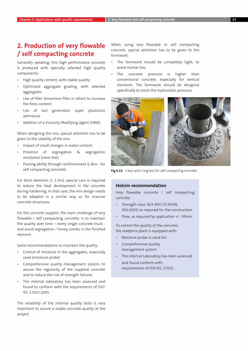
57
2. Production of very flowable / self compacting concreteGenerally speaking, this high performance concrete is produced with specially selected high quality components:
• High quality cement, with stable quality
• Optimized aggregate grading, with selected aggregates
• Use of filler (limestone filler or other) to increase the fines content
• Use of last generation super plasticizer admixture
• Addition of a Viscosity Modifying Agent (VMA)
When designing the mix, special attention has to be given to the stability of the mix:
• Impact of small changes in water content
• Presence of segregation & segregation resistance (sieve test)
• Passing ability through reinforcement (L Box - for self compacting concrete)
For thick elements (> 1.5m), special care is required to reduce the heat development in the concrete during hardening. In that case, the mix design needs to be adapted in a similar way as for massive concrete structures.
For the concrete supplier, the main challenge of very flowable / self compacting concrete, is to maintain the quality over time – every single concrete truck - and avoid segregation / honey combs in the finished element.
Some recommendations to maintain the quality:
• Control of moisture in the aggregates, especially sand (moisture probe)
• Comprehensive quality management system, to assure the regularity of the supplied concrete and to reduce the risk of strength failures.
• The internal laboratory has been assessed and found to conform with the requirements of ISO/IEC 17025:2005.
The reliability of the internal quality tests is very important to assure a stable concrete quality at the project.
When using very flowable or self compacting concrete, special attention has to be given to the formwork:
• The formwork should be completely tight, to avoid mortar loss
• The concrete pressure is higher than conventional concrete, especially for vertical elements. The formwork should be designed specifically to resist this hydrostatic pressure.
Chapter II: Applications with specific requirements E. Very flowable and self compacting concrete
Fig II.12 - L-box and J-ring test for self compacting concrete
Holcim recommendationVery flowable concrete / self compacting concrete
• Strength class: B25-B45 (TCXDVN 356:2005) as required for the construction
• Flow: as required by application +/- 50mm
To control the quality of the concrete, the readymix plant is equipped with:
• Moisture probe in sand bin
• Comprehensive quality management system
• The internal Laboratory has been assessed
and found conform with requirements of ISO/IEC 17025
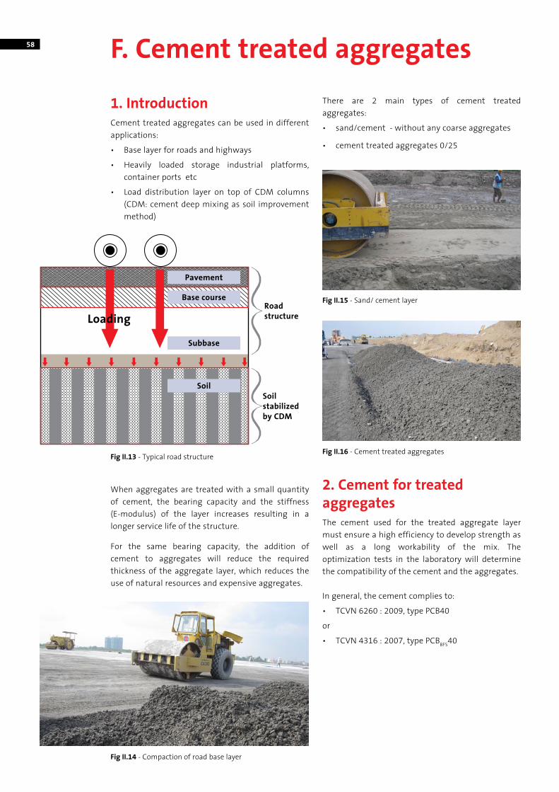
58 F. Cement treated aggregates
1. IntroductionCement treated aggregates can be used in different applications:
• Base layer for roads and highways
• Heavily loaded storage industrial platforms, container ports etc
• Load distribution layer on top of CDM columns (CDM: cement deep mixing as soil improvement method)
When aggregates are treated with a small quantity of cement, the bearing capacity and the stiffness (E-modulus) of the layer increases resulting in a longer service life of the structure.
For the same bearing capacity, the addition of cement to aggregates will reduce the required thickness of the aggregate layer, which reduces the use of natural resources and expensive aggregates.
There are 2 main types of cement treated aggregates:
• sand/cement - without any coarse aggregates
• cement treated aggregates 0/25
2. Cement for treated aggregatesThe cement used for the treated aggregate layer must ensure a high efficiency to develop strength as well as a long workability of the mix. The optimization tests in the laboratory will determine the compatibility of the cement and the aggregates.
In general, the cement complies to:
• TCVN 6260 : 2009, type PCB40
or
• TCVN 4316 : 2007, type PCBBFS40
Subbase
Soil
Base course
Pavement
Roadstructure
Soilstabilizedby CDM
Loading
Fig II.13 - Typical road structure
Fig II.14 - Compaction of road base layer
Fig II.15 - Sand/ cement layer
Fig II.16 - Cement treated aggregates
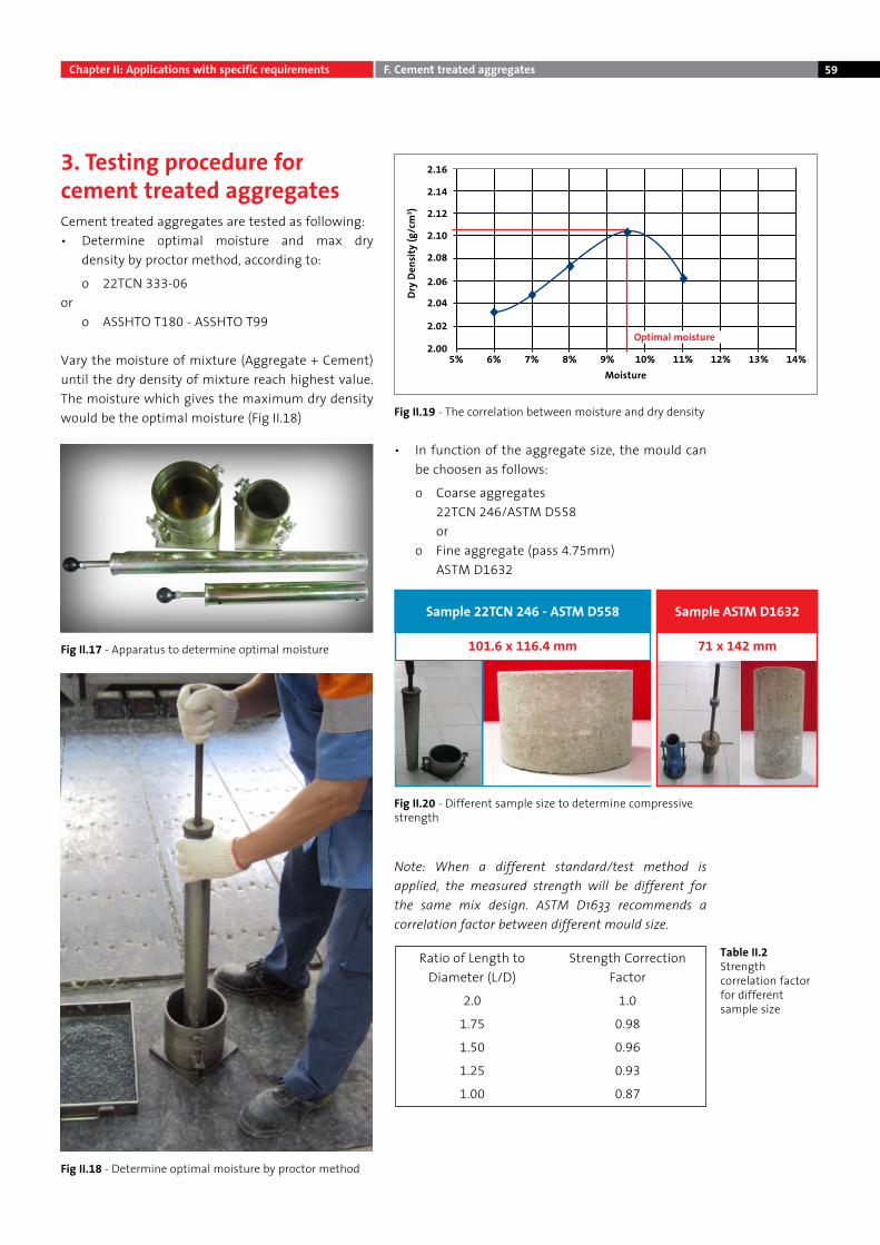
59
3. Testing procedure for cement treated aggregatesCement treated aggregates are tested as following:• Determine optimal moisture and max dry
density by proctor method, according to:
o 22TCN 333-06or
o ASSHTO T180 - ASSHTO T99
Vary the moisture of mixture (Aggregate + Cement) until the dry density of mixture reach highest value. The moisture which gives the maximum dry density would be the optimal moisture (Fig II.18)
• In function of the aggregate size, the mould can be choosen as follows:
o Coarse aggregates 22TCN 246/ASTM D558 or
o Fine aggregate (pass 4.75mm) ASTM D1632
Note: When a different standard/test method is applied, the measured strength will be different for the same mix design. ASTM D1633 recommends a correlation factor between different mould size.
Sample 22TCN 246 - ASTM D558 Sample ASTM D1632
71 x 142 mm101.6 x 116.4 mm
Ratio of Length to Diameter (L/D)
Strength Correction Factor
2.0 1.0
1.75 0.98
1.50 0.96
1.25 0.93
1.00 0.87
2.005% 6% 7% 8% 9% 10% 11% 12% 13% 14%
2.02
2.04
2.06
2.08
2.10
2.12
2.14
Dry
Dens
ity (g
/cm
3 )
Moisture
2.16
Optimal moisture
Fig II.17 - Apparatus to determine optimal moisture
Fig II.19 - The correlation between moisture and dry density
Fig II.20 - Different sample size to determine compressive strength
Table II.2Strength correlation factor for different sample size
Fig II.18 - Determine optimal moisture by proctor method
Chapter II: Applications with specific requirements F. Cement treated aggregates
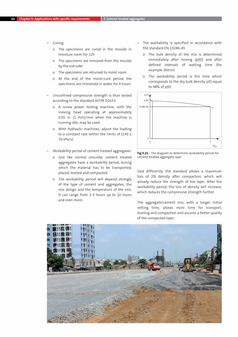
60 Chapter II: Applications with specific requirements F. Cement treated aggregates
• Curing
o The specimens are cured in the moulds in moisture room for 12h
o The specimens are removed from the moulds by the extruder
o The specimens are returned to moist room
o At the end of the moist–cure period, the specimens are immersed in water for 4 hours
• Unconfined compressive strength is than tested according to the standard ASTM D1633
o A screw power testing machine, with the moving head operating at approximately 0.05 in. (1 mm)/min when the machine is running idle, may be used
o With hydraulic machines, adjust the loading to a constant rate within the limits of (140 ± 70 kPa/s)
• Workability period of cement treated aggregates
o Just like normal concrete, cement treated aggregates have a workability period, during which the material has to be transported, placed, leveled and compacted.
o The workability period will depend strongly of the type of cement and aggregates, the mix design and the temperature of the mix. It can range from 2-3 hours up to 10 hours and even more.
• The workability is specified in accordance with the standard EN 13286-45
o The bulk density of the mix is determined immediately after mixing (p(0)) and after defined intervals of waiting time (for example 30min)
o The workability period is the time which corresponds to the dry bulk density p(t) equal to 98% of p(0)
Said differently, the standard allows a maximum loss of 2% density after compaction, which will already reduce the strength of the layer. After the workability period, the loss of density will increase, which reduces the compressive strength further.
The aggregate/cement mix, with a longer initial setting time, allows more time for transport, leveling and compaction and assures a better quality of the compacted layer.
p (t)
p (0)
0,98p (0)
0fs f
Wpc
Fig II.21 - The diagram to determine workability period for cement treated aggregate layer
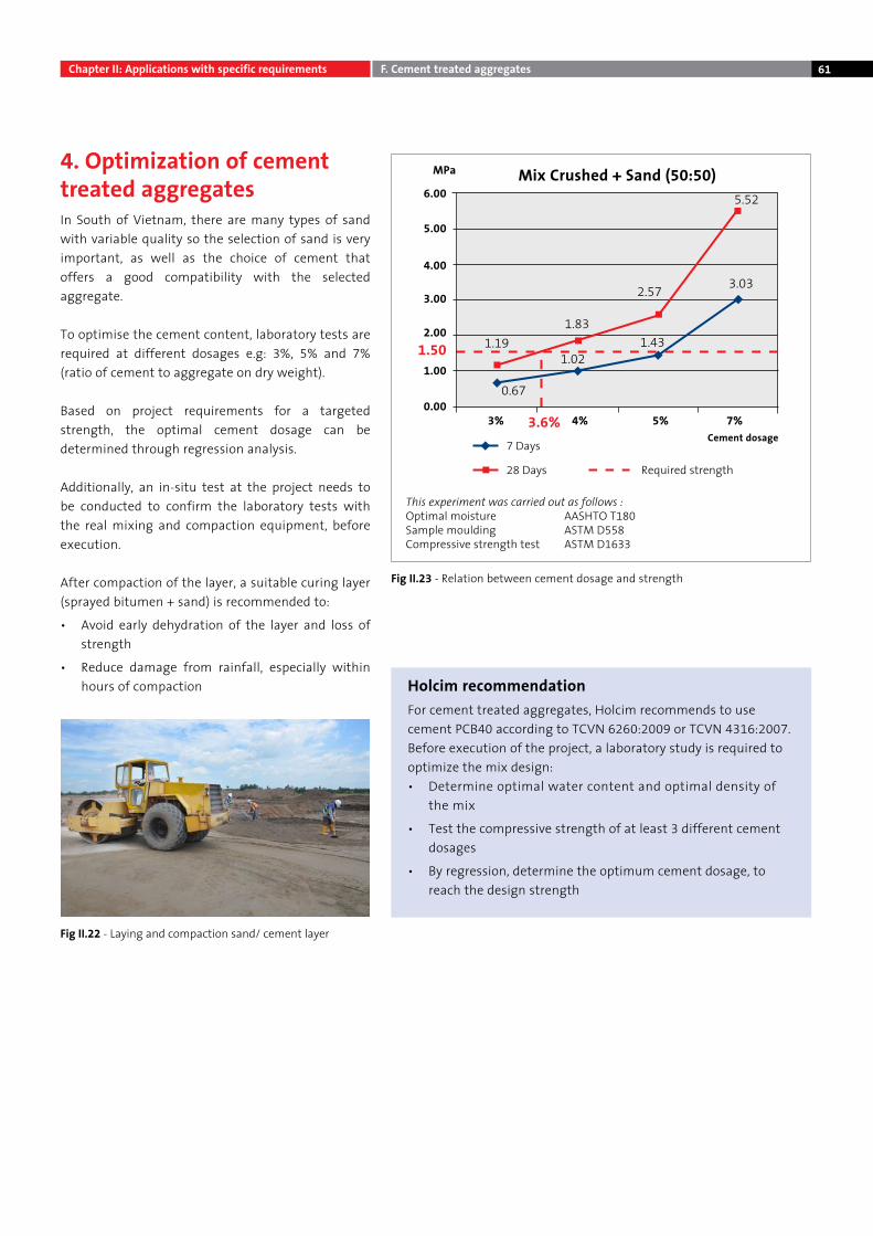
61
4. Optimization of cement treated aggregatesIn South of Vietnam, there are many types of sand with variable quality so the selection of sand is very important, as well as the choice of cement that offers a good compatibility with the selected aggregate.
To optimise the cement content, laboratory tests are required at different dosages e.g: 3%, 5% and 7% (ratio of cement to aggregate on dry weight).
Based on project requirements for a targeted strength, the optimal cement dosage can be determined through regression analysis.
Additionally, an in-situ test at the project needs to be conducted to confirm the laboratory tests with the real mixing and compaction equipment, before execution.
After compaction of the layer, a suitable curing layer (sprayed bitumen + sand) is recommended to:
• Avoid early dehydration of the layer and loss of strength
• Reduce damage from rainfall, especially within hours of compaction Holcim recommendation
For cement treated aggregates, Holcim recommends to use cement PCB40 according to TCVN 6260:2009 or TCVN 4316:2007.Before execution of the project, a laboratory study is required to optimize the mix design:• Determine optimal water content and optimal density of
the mix
• Test the compressive strength of at least 3 different cement dosages
• By regression, determine the optimum cement dosage, to reach the design strength
6.00
MPa
5.00
4.00
3.00
2.00
1.00
0.003% 4% 5% 7%3.6%
1.191.83
1.02
28 Days Required strength
This experiment was carried out as follows :Optimal moisture AASHTO T180Sample moulding ASTM D558Compressive strength test ASTM D1633
0.67
2.57
1.43
3.03
5.52
1.50
Mix Crushed + Sand (50:50)
Cement dosage7 Days
Chapter II: Applications with specific requirements F. Cement treated aggregates
Fig II.22 - Laying and compaction sand/ cement layer
Fig II.23 - Relation between cement dosage and strength
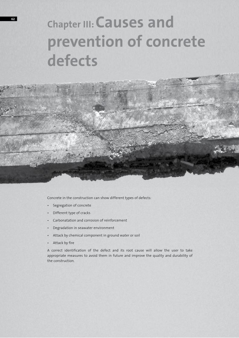
62
Chapter III: Causes and prevention of concrete defects
Concrete in the construction can show different types of defects:
• Segregation of concrete
• Different type of cracks
• Carbonatation and corrosion of reinforcement
• Degradation in seawater environment
• Attack by chemical component in ground water or soil
• Attack by fire
A correct identification of the defect and its root cause will allow the user to take appropriate measures to avoid them in future and improve the quality and durability of the construction.
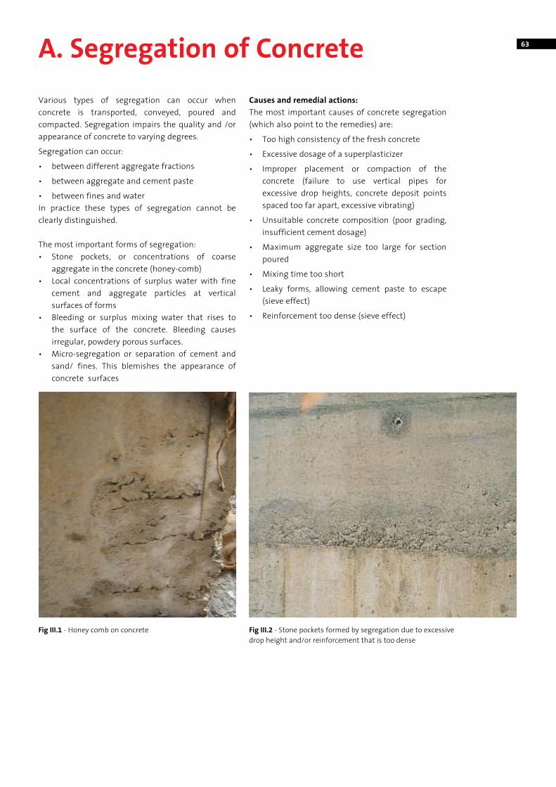
63A. Segregation of Concrete
Various types of segregation can occur when concrete is transported, conveyed, poured and compacted. Segregation impairs the quality and /or appearance of concrete to varying degrees.
Segregation can occur:
• between different aggregate fractions
• between aggregate and cement paste
• between fines and waterIn practice these types of segregation cannot be clearly distinguished.
The most important forms of segregation:• Stone pockets, or concentrations of coarse
aggregate in the concrete (honey-comb)• Local concentrations of surplus water with fine
cement and aggregate particles at vertical surfaces of forms
• Bleeding or surplus mixing water that rises to the surface of the concrete. Bleeding causes irregular, powdery porous surfaces.
• Micro-segregation or separation of cement and sand/ fines. This blemishes the appearance of concrete surfaces
Causes and remedial actions:The most important causes of concrete segregation (which also point to the remedies) are:
• Too high consistency of the fresh concrete
• Excessive dosage of a superplasticizer
• Improper placement or compaction of the concrete (failure to use vertical pipes for excessive drop heights, concrete deposit points spaced too far apart, excessive vibrating)
• Unsuitable concrete composition (poor grading, insufficient cement dosage)
• Maximum aggregate size too large for section poured
• Mixing time too short
• Leaky forms, allowing cement paste to escape (sieve effect)
• Reinforcement too dense (sieve effect)
Fig III.2 - Stone pockets formed by segregation due to excessive drop height and/or reinforcement that is too dense
Fig III.1 - Honey comb on concrete
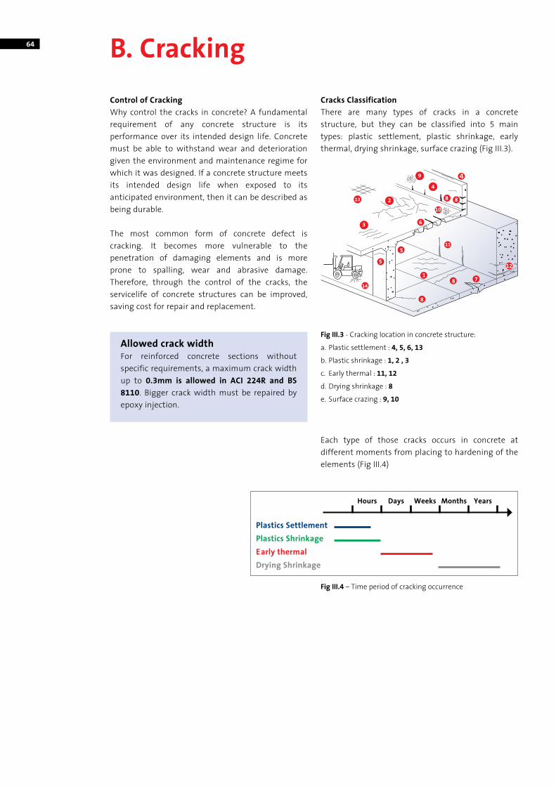
64 B. Cracking
Control of CrackingWhy control the cracks in concrete? A fundamental requirement of any concrete structure is its performance over its intended design life. Concrete must be able to withstand wear and deterioration given the environment and maintenance regime for which it was designed. If a concrete structure meets its intended design life when exposed to its anticipated environment, then it can be described as being durable.
The most common form of concrete defect is cracking. It becomes more vulnerable to the penetration of damaging elements and is more prone to spalling, wear and abrasive damage. Therefore, through the control of the cracks, the servicelife of concrete structures can be improved, saving cost for repair and replacement.
Cracks ClassificationThere are many types of cracks in a concrete structure, but they can be classified into 5 main types: plastic settlement, plastic shrinkage, early thermal, drying shrinkage, surface crazing (Fig III.3).
Each type of those cracks occurs in concrete at different moments from placing to hardening of the elements (Fig III.4)
Fig III.3 - Cracking location in concrete structure:
a. Plastic settlement : 4, 5, 6, 13
b. Plastic shrinkage : 1, 2 , 3
c. Early thermal : 11, 12
d. Drying shrinkage : 8
e. Surface crazing : 9, 10
Fig III.4 – Time period of cracking occurrence
Plastics SettlementPlastics ShrinkageEarly thermalDrying Shrinkage
Hours Days Weeks Months Years
Allowed crack widthFor reinforced concrete sections without specific requirements, a maximum crack width up to 0.3mm is allowed in ACI 224R and BS 8110. Bigger crack width must be repaired by epoxy injection.
9
2
6
13
3
5
5
14
1
8
8 7
11
12
8 8
44
10
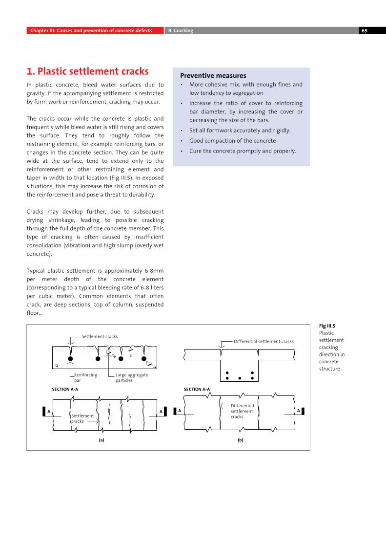
65
1. Plastic settlement cracksIn plastic concrete, bleed water surfaces due to gravity. If the accompanying settlement is restricted by form work or reinforcement, cracking may occur.
The cracks occur while the concrete is plastic and frequently while bleed water is still rising and covers the surface. They tend to roughly follow the restraining element, for example reinforcing bars, or changes in the concrete section. They can be quite wide at the surface, tend to extend only to the reinforcement or other restraining element and taper in width to that location (Fig III.5). In exposed situations, this may increase the risk of corrosion of the reinforcement and pose a threat to durability.
Cracks may develop further, due to subsequent drying shrinkage, leading to possible cracking through the full depth of the concrete member. This type of cracking is often caused by insufficient consolidation (vibration) and high slump (overly wet concrete).
Typical plastic settlement is approximately 6-8mm per meter depth of the concrete element (corresponding to a typical bleeding rate of 6-8 liters per cubic meter). Common elements that often crack, are deep sections, top of column, suspended floor…
Fig III.5 Plastic settlement cracking direction in concrete structure
Preventive measures• More cohesive mix, with enough fines and
low tendency to segregation
• Increase the ratio of cover to reinforcing bar diameter, by increasing the cover or decreasing the size of the bars.
• Set all formwork accurately and rigidly.
• Good compaction of the concrete
• Cure the concrete promptly and properly.
Settlement cracks
SECTION A-A
A
(a) (b)
A A A
SECTION A-A
Settlement cracks
Reinforcing bar
Large aggregate particles
Differential settlement cracks
Differential settlement cracks
Chapter III: Causes and prevention of concrete defects B. Cracking
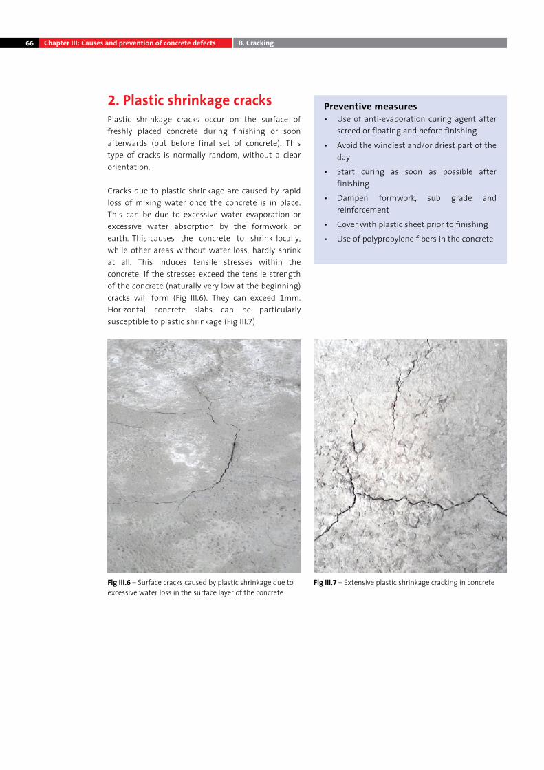
66
2. Plastic shrinkage cracksPlastic shrinkage cracks occur on the surface of freshly placed concrete during finishing or soon afterwards (but before final set of concrete). This type of cracks is normally random, without a clear orientation.
Cracks due to plastic shrinkage are caused by rapid loss of mixing water once the concrete is in place. This can be due to excessive water evaporation or excessive water absorption by the formwork or earth. This causes the concrete to shrink locally, while other areas without water loss, hardly shrink at all. This induces tensile stresses within the concrete. If the stresses exceed the tensile strength of the concrete (naturally very low at the beginning) cracks will form (Fig III.6). They can exceed 1mm. Horizontal concrete slabs can be particularly susceptible to plastic shrinkage (Fig III.7)
Fig III.6 – Surface cracks caused by plastic shrinkage due to excessive water loss in the surface layer of the concrete
Fig III.7 – Extensive plastic shrinkage cracking in concrete
Preventive measures• Use of anti-evaporation curing agent after
screed or floating and before finishing
• Avoid the windiest and/or driest part of the day
• Start curing as soon as possible after finishing
• Dampen formwork, sub grade and reinforcement
• Cover with plastic sheet prior to finishing
• Use of polypropylene fibers in the concrete
Chapter III: Causes and prevention of concrete defects B. Cracking
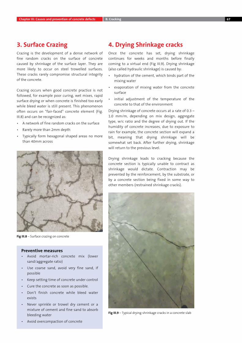
67
3. Surface CrazingCrazing is the development of a dense network of fine random cracks on the surface of concrete caused by shrinkage of the surface layer. They are more likely to occur on steel trowelled surfaces. These cracks rarely compromise structural integrity of the concrete.
Crazing occurs when good concrete practice is not followed, for example poor curing, wet mixes, rapid surface drying or when concrete is finished too early while bleed water is still present. This phenomenon often occurs on “fair-faced” concrete element (Fig.III.8) and can be recognized as:
• A network of fine random cracks on the surface
• Rarely more than 2mm depth
• Typically form hexagonal shaped areas no more than 40mm across
4. Drying Shrinkage cracksOnce the concrete has set, drying shrinkage continues for weeks and months before finally coming to a virtual end (Fig III.9). Drying shrinkage (also called hydraulic shrinkage) is caused by:
• hydration of the cement, which binds part of the mixing water
• evaporation of mixing water from the concrete surface
• initial adjustment of the temperature of the concrete to that of the environment
Drying shrinkage of concrete occurs at a rate of 0.3 – 1.0 mm/m, depending on mix design, aggregate type, w/c ratio and the degree of drying out. If the humidity of concrete increases, due to exposure to rain for example, the concrete section will expand a bit, meaning that drying shrinkage will be somewhat set back. After further drying, shrinkage will return to the previous level.
Drying shrinkage leads to cracking because the concrete section is typically unable to contract as shrinkage would dictate. Contraction may be prevented by the reinforcement, by the substrate, or by a concrete section being fixed in some way to other members (restrained shrinkage cracks).
Fig III.9 – Typical drying-shrinkage cracks in a concrete slab
Fig III.8 – Surface crazing on concrete
Preventive measures• Avoid mortar-rich concrete mix (lower
sand/aggregate ratio)
• Use coarse sand, avoid very fine sand, if possible
• Keep setting time of concrete under control
• Cure the concrete as soon as possible.
• Don’t finish concrete while bleed water exists
• Never sprinkle or trowel dry cement or a mixture of cement and fine sand to absorb bleeding water
• Avoid overcompaction of concrete
B. CrackingChapter III: Causes and prevention of concrete defects
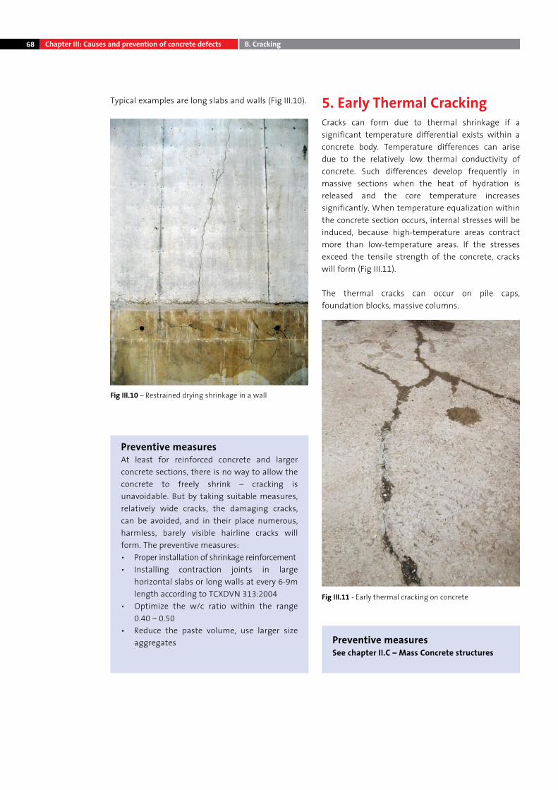
68
Typical examples are long slabs and walls (Fig III.10). 5. Early Thermal CrackingCracks can form due to thermal shrinkage if a significant temperature differential exists within a concrete body. Temperature differences can arise due to the relatively low thermal conductivity of concrete. Such differences develop frequently in massive sections when the heat of hydration is released and the core temperature increases significantly. When temperature equalization within the concrete section occurs, internal stresses will be induced, because high-temperature areas contract more than low-temperature areas. If the stresses exceed the tensile strength of the concrete, cracks will form (Fig III.11).
The thermal cracks can occur on pile caps, foundation blocks, massive columns.
Fig III.10 – Restrained drying shrinkage in a wall
Fig III.11 - Early thermal cracking on concrete
Preventive measuresAt least for reinforced concrete and larger concrete sections, there is no way to allow the concrete to freely shrink – cracking is unavoidable. But by taking suitable measures, relatively wide cracks, the damaging cracks, can be avoided, and in their place numerous, harmless, barely visible hairline cracks will form. The preventive measures:• Proper installation of shrinkage reinforcement• Installing contraction joints in large
horizontal slabs or long walls at every 6-9m length according to TCXDVN 313:2004
• Optimize the w/c ratio within the range 0.40 – 0.50
• Reduce the paste volume, use larger size aggregates Preventive measures
See chapter II.C – Mass Concrete structures
Chapter III: Causes and prevention of concrete defects B. Cracking
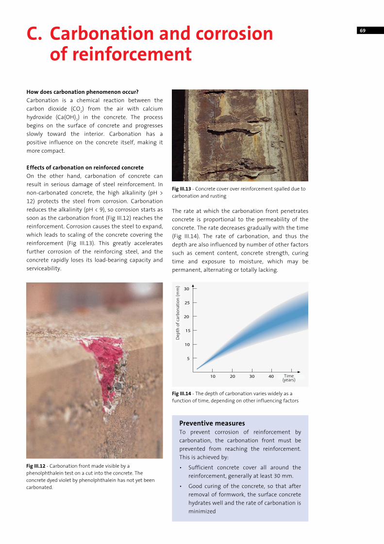
69C. Carbonation and corrosion of reinforcement
How does carbonation phenomenon occur?Carbonation is a chemical reaction between the carbon dioxide (CO2) from the air with calcium hydroxide (Ca(OH)2) in the concrete. The process begins on the surface of concrete and progresses slowly toward the interior. Carbonation has a positive influence on the concrete itself, making it more compact.
Effects of carbonation on reinforced concreteOn the other hand, carbonation of concrete can result in serious damage of steel reinforcement. In non-carbonated concrete, the high alkalinity (pH > 12) protects the steel from corrosion. Carbonation reduces the alkalinity (pH < 9), so corrosion starts as soon as the carbonation front (Fig III.12) reaches the reinforcement. Corrosion causes the steel to expand, which leads to scaling of the concrete covering the reinforcement (Fig III.13). This greatly accelerates further corrosion of the reinforcing steel, and the concrete rapidly loses its load-bearing capacity and serviceability.
The rate at which the carbonation front penetrates concrete is proportional to the permeability of the concrete. The rate decreases gradually with the time (Fig III.14). The rate of carbonation, and thus the depth are also influenced by number of other factors such as cement content, concrete strength, curing time and exposure to moisture, which may be permanent, alternating or totally lacking.
Fig III.12 - Carbonation front made visible by a phenolphthalein test on a cut into the concrete. The concrete dyed violet by phenolphthalein has not yet been carbonated.
Fig III.14 - The depth of carbonation varies widely as a function of time, depending on other influencing factors
Fig III.13 - Concrete cover over reinforcement spalled due to carbonation and rusting
Preventive measuresTo prevent corrosion of reinforcement by carbonation, the carbonation front must be prevented from reaching the reinforcement. This is achieved by:
• Sufficient concrete cover all around the reinforcement, generally at least 30 mm.
• Good curing of the concrete, so that after removal of formwork, the surface concrete hydrates well and the rate of carbonation is minimized
Thời gian (năm)
Chiề
u sâ
u ca
cbon
at h
óa (m
m)
Time(years)
Dep
th o
f car
bona
tion
(mm
)
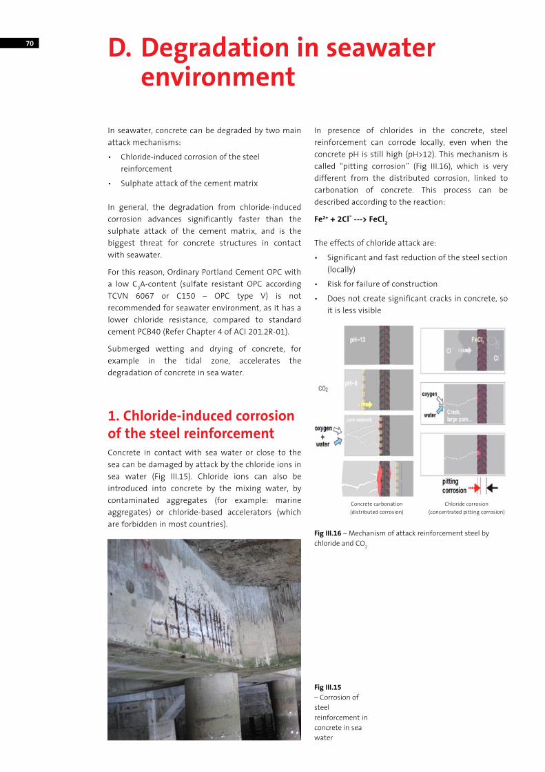
70 D. Degradation in seawater environment
In seawater, concrete can be degraded by two main attack mechanisms:
• Chloride-induced corrosion of the steel reinforcement
• Sulphate attack of the cement matrix
In general, the degradation from chloride-induced corrosion advances significantly faster than the sulphate attack of the cement matrix, and is the biggest threat for concrete structures in contact with seawater.
For this reason, Ordinary Portland Cement OPC with a low C3A-content (sulfate resistant OPC according TCVN 6067 or C150 – OPC type V) is not recommended for seawater environment, as it has a lower chloride resistance, compared to standard cement PCB40 (Refer Chapter 4 of ACI 201.2R-01).
Submerged wetting and drying of concrete, for example in the tidal zone, accelerates the degradation of concrete in sea water.
1. Chloride-induced corrosion of the steel reinforcementConcrete in contact with sea water or close to the sea can be damaged by attack by the chloride ions in sea water (Fig III.15). Chloride ions can also be introduced into concrete by the mixing water, by contaminated aggregates (for example: marine aggregates) or chloride-based accelerators (which are forbidden in most countries).
In presence of chlorides in the concrete, steel reinforcement can corrode locally, even when the concrete pH is still high (pH>12). This mechanism is called “pitting corrosion” (Fig III.16), which is very different from the distributed corrosion, linked to carbonation of concrete. This process can be described according to the reaction:
Fe2+ + 2Cl- ---> FeCl2
The effects of chloride attack are:
• Significant and fast reduction of the steel section (locally)
• Risk for failure of construction
• Does not create significant cracks in concrete, so it is less visible
Fig III.15 – Corrosion of steel reinforcement in concrete in sea water
Fig III.16 – Mechanism of attack reinforcement steel by chloride and CO2
Concrete carbonation (distributed corrosion)
Chloride corrosion (concentrated pitting corrosion)
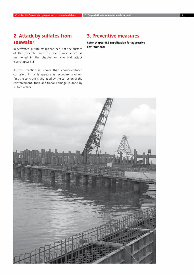
71
2. Attack by sulfates from seawaterIn seawater, sulfate attack can occur at the surface of the concrete, with the same mechanism as mentioned in the chapter on chemical attack (see chapter III.E)
As this reaction is slower than choride-induced corrosion, it mainly appears as secondary reaction: first the concrete is degraded by the corrosion of the reinforcement, then additional damage is done by sulfate attack.
3. Preventive measuresRefer chapter II.B (Application for aggressive environment)
Chapter III: Causes and prevention of concrete defects D. Degradation in seawater environment
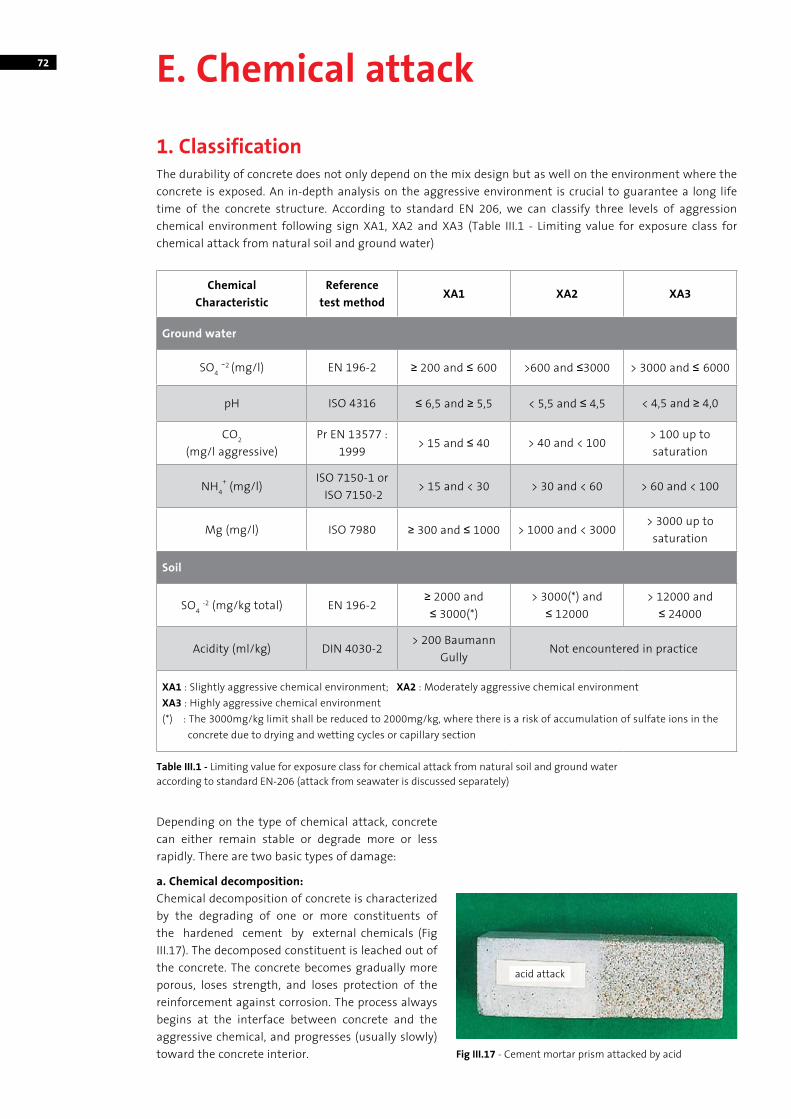
72 E. Chemical attack
1. ClassificationThe durability of concrete does not only depend on the mix design but as well on the environment where the concrete is exposed. An in-depth analysis on the aggressive environment is crucial to guarantee a long life time of the concrete structure. According to standard EN 206, we can classify three levels of aggression chemical environment following sign XA1, XA2 and XA3 (Table III.1 - Limiting value for exposure class for chemical attack from natural soil and ground water)
Chemical Characteristic
Reference test method
XA1 XA2 XA3
Ground water
SO4 -2 (mg/l) EN 196-2 ≥ 200 and ≤ 600 >600 and ≤3000 > 3000 and ≤ 6000
pH ISO 4316 ≤ 6,5 and ≥ 5,5 < 5,5 and ≤ 4,5 < 4,5 and ≥ 4,0
CO2
(mg/l aggressive)Pr EN 13577 :
1999> 15 and ≤ 40 > 40 and < 100
> 100 up to saturation
NH4+ (mg/l)
ISO 7150-1 or ISO 7150-2
> 15 and < 30 > 30 and < 60 > 60 and < 100
Mg (mg/l) ISO 7980 ≥ 300 and ≤ 1000 > 1000 and < 3000> 3000 up to
saturation
Soil
SO4 -2 (mg/kg total) EN 196-2≥ 2000 and≤ 3000(*)
> 3000(*) and ≤ 12000
> 12000 and ≤ 24000
Acidity (ml/kg) DIN 4030-2> 200 Baumann
GullyNot encountered in practice
XA1 : Slightly aggressive chemical environment; XA2 : Moderately aggressive chemical environmentXA3 : Highly aggressive chemical environment(*) : The 3000mg/kg limit shall be reduced to 2000mg/kg, where there is a risk of accumulation of sulfate ions in the
concrete due to drying and wetting cycles or capillary section
Table III.1 - Limiting value for exposure class for chemical attack from natural soil and ground wateraccording to standard EN-206 (attack from seawater is discussed separately)
Depending on the type of chemical attack, concrete can either remain stable or degrade more or less rapidly. There are two basic types of damage:
a. Chemical decomposition:Chemical decomposition of concrete is characterized by the degrading of one or more constituents of the hardened cement by external chemicals (Fig III.17). The decomposed constituent is leached out of the concrete. The concrete becomes gradually more porous, loses strength, and loses protection of the reinforcement against corrosion. The process always begins at the interface between concrete and the aggressive chemical, and progresses (usually slowly) toward the concrete interior. Fig III.17 - Cement mortar prism attacked by acid
acid attack
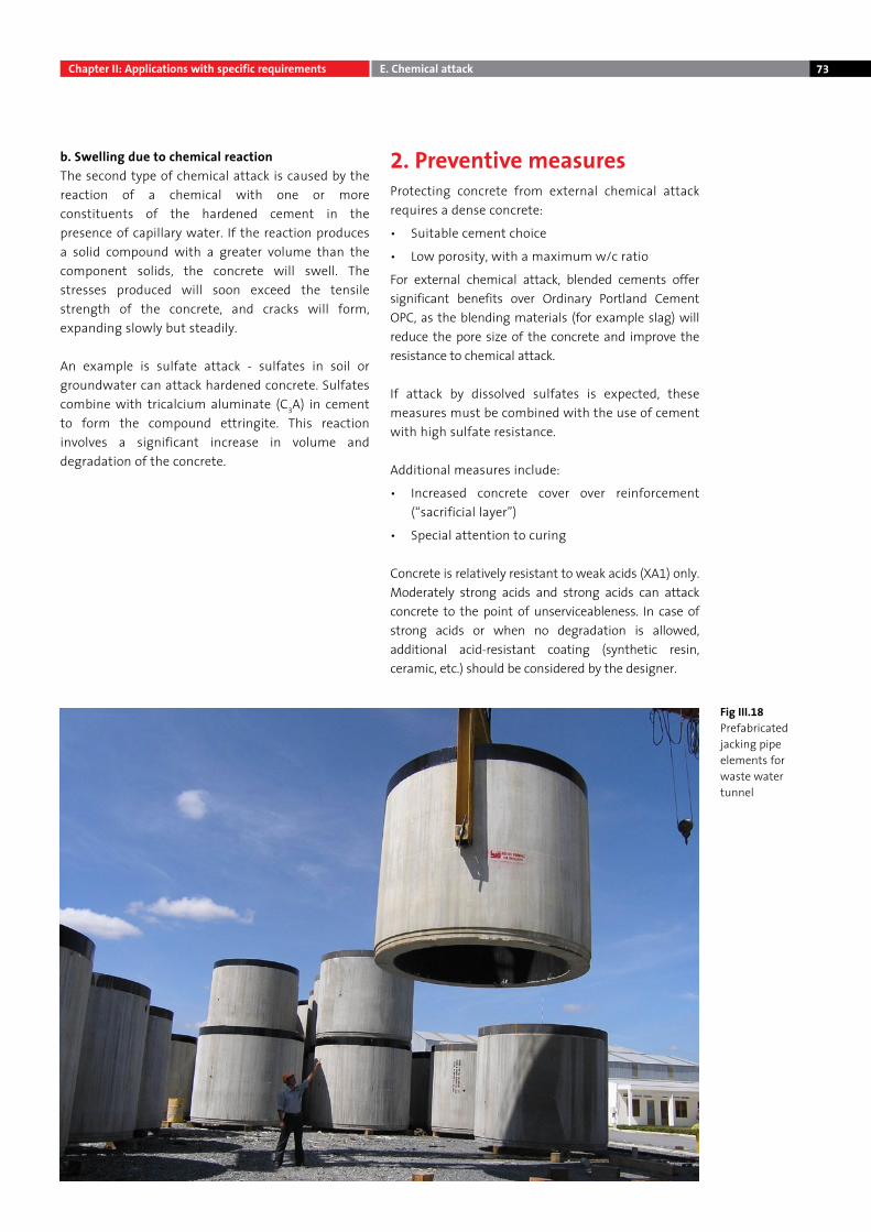
73
Fig III.18Prefabricated jacking pipe elements for waste water tunnel
b. Swelling due to chemical reactionThe second type of chemical attack is caused by the reaction of a chemical with one or more constituents of the hardened cement in the presence of capillary water. If the reaction produces a solid compound with a greater volume than the component solids, the concrete will swell. The stresses produced will soon exceed the tensile strength of the concrete, and cracks will form, expanding slowly but steadily.
An example is sulfate attack - sulfates in soil or groundwater can attack hardened concrete. Sulfates combine with tricalcium aluminate (C3A) in cement to form the compound ettringite. This reaction involves a significant increase in volume and degradation of the concrete.
2. Preventive measuresProtecting concrete from external chemical attack requires a dense concrete:
• Suitable cement choice
• Low porosity, with a maximum w/c ratio
For external chemical attack, blended cements offer significant benefits over Ordinary Portland Cement OPC, as the blending materials (for example slag) will reduce the pore size of the concrete and improve the resistance to chemical attack.
If attack by dissolved sulfates is expected, these measures must be combined with the use of cement with high sulfate resistance.
Additional measures include:
• Increased concrete cover over reinforcement (“sacrificial layer”)
• Special attention to curing
Concrete is relatively resistant to weak acids (XA1) only. Moderately strong acids and strong acids can attack concrete to the point of unserviceableness. In case of strong acids or when no degradation is allowed, additional acid-resistant coating (synthetic resin, ceramic, etc.) should be considered by the designer.
Chapter II: Applications with specific requirements E. Chemical attack
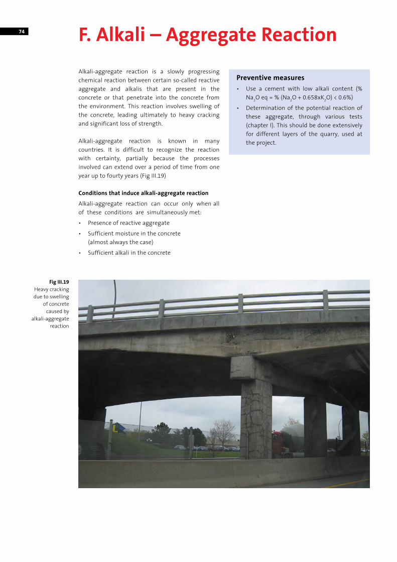
74 F. Alkali – Aggregate Reaction
Alkali-aggregate reaction is a slowly progressing chemical reaction between certain so-called reactive aggregate and alkalis that are present in the concrete or that penetrate into the concrete from the environment. This reaction involves swelling of the concrete, leading ultimately to heavy cracking and significant loss of strength.
Alkali-aggregate reaction is known in many countries. It is difficult to recognize the reaction with certainty, partially because the processes involved can extend over a period of time from one year up to fourty years (Fig III.19)
Conditions that induce alkali-aggregate reaction
Alkali-aggregate reaction can occur only when all of these conditions are simultaneously met:
• Presence of reactive aggregate
• Sufficient moisture in the concrete (almost always the case)
• Sufficient alkali in the concrete
Fig III.19 Heavy cracking due to swelling
of concrete caused by
alkali-aggregate reaction
Preventive measures• Use a cement with low alkali content (%
Na2O eq = % (Na2O + 0.658xK2O) < 0.6%)
• Determination of the potential reaction of these aggregate, through various tests (chapter I). This should be done extensively for different layers of the quarry, used at the project.
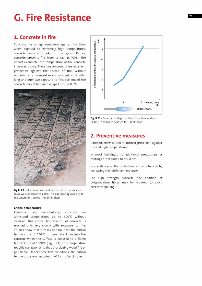
75G. Fire Resistance
1. Concrete in fireConcrete has a high resistance against fire. Even when exposed to extremely high temperatures, concrete emits no smoke or toxic gases. Rather, concrete prevents fire from spreading. When fire impacts concrete, the temperature of the concrete increases slowly. Therefore concrete offers excellent protection against the spread of fire, without requiring any fire-resistance treatment. Only after long and intensive exposure to fire, portions of the concrete may delaminate or spall off (Fig III.20).
Critical temperature:Reinforced and non-reinforced concrete can withstand temperatures up to 300°C without damage. This critical temperature of concrete is reached only very slowly with exposure to fire. Studies show that it takes one hour for the critical temperature of 300°C to penetrate 2 cm into the concrete when the surface is exposed to a flame temperature of 1000°C (Fig III.21). This temperature roughly corresponds to that of a blazing wood fire or gas flame. Under these test conditions, the critical temperature reaches a depth of 5 cm after 2 hours.
2. Preventive measures Concrete offers excellent intrinsic protection against fire and high temperatures.
In most buildings, no additional precautions or coatings are required to resist fire.
In specific cases, the protection can be enhanced by increasing the reinforcement cover.
For high strength concrete, the addition of polypropylene fibres may be required to avoid excessive spalling.
Fig III.20 – Steel reinforcement exposed after the concrete cover was spalled off in a fire. The load-bearing capacity of the concrete structure is undiminished.
Fig III.21 - Penetration depth of the critical temperature (300°C) in concrete exposed to 1000°C heat.
76
Chapter IV: Overview of cement and concrete standards
A. CementVIETNAMESE STANDARDS – TCVN
• Portland Blended Cement – Specifications TCVN 6260 : 2009
• Portland Cement – Specifications TCVN 2682 : 2009
• Portland Blast Furnace Slag Cement TCVN 4316 : 2007
• Sulfate Resistant Portland Cement TCVN 6067 : 2004
• Sulfate Resistant Blended Portland Cement TCVN 7711 : 2007
• Low Heat Blended Portland Cement TCVN 7712 : 2007
AMERICAN STANDARDS - ASTM
• Standard Performance Specification For Hydraulic Cement
ASTM C1157 : 2008
• Ordinary Portland cement – Specifications ASTM C150 : 2011
EUROPEAN STANDARDS - BS-EN
• Composition, Specifications and Conformity Criteria for Common Cement
EN 197-1: 2011
B. ConcreteVIETNAMESE STANDARDS – TCVN
• TCXDVN 374:2006
AMERICAN STANDARDS – ASTM
• ASTM C94
EUROPEAN STANDARDS – EN
• EN 206-1:2000
BRITISH STANDARDS – BS
• BS 5328
C. Recommendation for limiting values of concrete composition• Chloride - induced corrosion in sea water
(EN 206-1:2000)
• Aggressive chemical environments (EN 206-1:2000)
To understand quickly the requirements of each standard, this chapter gives an overview of the main referenced standards in this manual. For the complete details of each standard, please refer to the official standard itself.
As worldwide there are many standards available, this overview only lists the standards that are currently used in Vietnam.
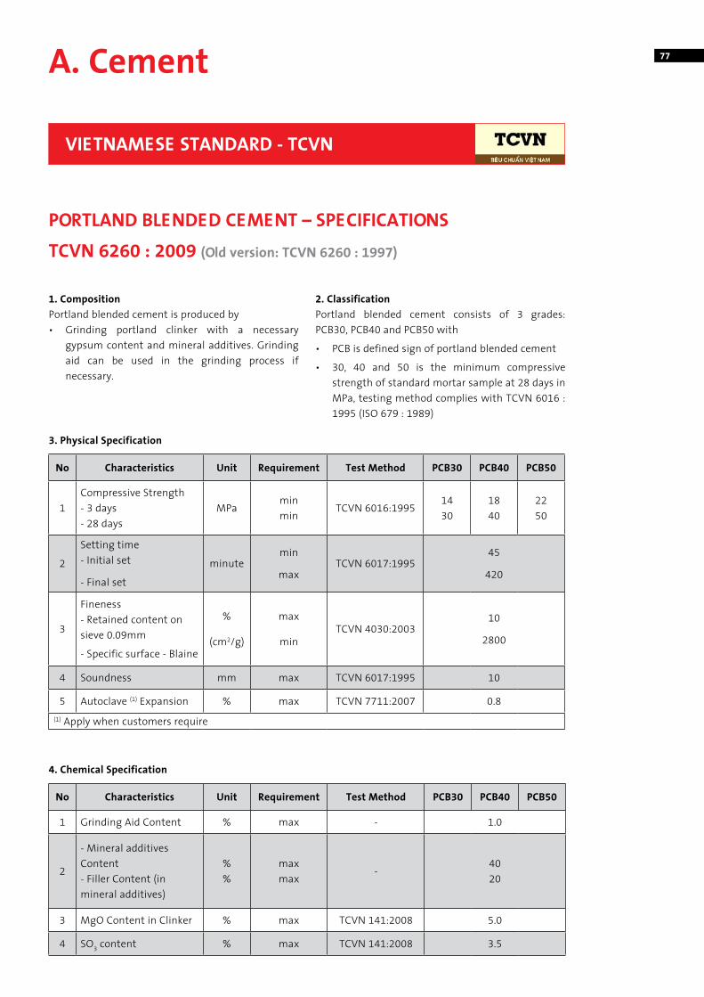
77A. Cement
1. CompositionPortland blended cement is produced by• Grinding portland clinker with a necessary
gypsum content and mineral additives. Grinding aid can be used in the grinding process if necessary.
2. ClassificationPortland blended cement consists of 3 grades: PCB30, PCB40 and PCB50 with
• PCB is defined sign of portland blended cement
• 30, 40 and 50 is the minimum compressive strength of standard mortar sample at 28 days in MPa, testing method complies with TCVN 6016 : 1995 (ISO 679 : 1989)
VIETNAMESE STANDARD - TCVN
PORTLAND BLENDED CEMENT – SPECIFICATIONS TCVN 6260 : 2009 (Old version: TCVN 6260 : 1997)
No Characteristics Unit Requirement Test Method PCB30 PCB40 PCB50
1Compressive Strength - 3 days- 28 days
MPaminmin
TCVN 6016:19951430
1840
2250
2
Setting time - Initial set
- Final set
minutemin
maxTCVN 6017:1995
45
420
3
Fineness- Retained content on sieve 0.09mm
- Specific surface - Blaine
%
(cm2/g)
max
minTCVN 4030:2003
10
2800
4 Soundness mm max TCVN 6017:1995 10
5 Autoclave (1) Expansion % max TCVN 7711:2007 0.8(1) Apply when customers require
No Characteristics Unit Requirement Test Method PCB30 PCB40 PCB50
1 Grinding Aid Content % max - 1.0
2
- Mineral additives Content - Filler Content (in mineral additives)
%%
maxmax
-4020
3 MgO Content in Clinker % max TCVN 141:2008 5.0
4 SO3 content % max TCVN 141:2008 3.5
3. Physical Specification
4. Chemical Specification
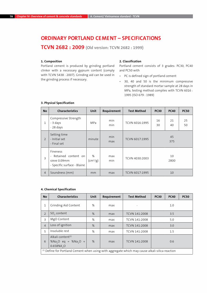
78 Chapter IV: Overview of cement & concrete standards A. Cement/ Vietnamese standard - TCVN
1. CompositionPortland cement is produced by grinding portland clinker with a necessary gypsum content (comply with TCVN 5438 : 2007). Grinding aid can be used in the grinding process if necessary.
2. ClassificationPortland cement consists of 3 grades: PC30, PC40 and PC50 with
• PC is defined sign of portland cement
• 30, 40 and 50 is the minimum compressive strength of standard mortar sample at 28 days in MPa, testing method complies with TCVN 6016 : 1995 (ISO 679 : 1989)
3. Physical Specification
4. Chemical Specification
ORDINARY PORTLAND CEMENT – SPECIFICATIONSTCVN 2682 : 2009 (Old version: TCVN 2682 : 1999)
No Characteristics Unit Requirement Test Method PC30 PC40 PC50
1Compressive Strength - 3 days- 28 days
MPaminmin
TCVN 6016:19951630
2140
2550
2Setting time - Initial set- Final set
minuteminmax
TCVN 6017:199545
375
3
Fineness- Retained content on sieve 0.09mm- Specific surface - Blaine
%(cm2/g)
maxmin
TCVN 4030:200310
2800
4 Soundness (mm) mm max TCVN 6017:1995 10
No Characteristics Unit Requirement Test Method PC30 PC40 PC50
1 Grinding Aid Content % max - 1.0
2 SO3 content % max TCVN 141:2008 3.5
3 MgO Content % max TCVN 141:2008 5.0
4 Loss of ignition % max TCVN 141:2008 3.0
5 Insoluble rest % max TCVN 141:2008 1.5
6Alkali content(1) %Na2O eq = %Na2O + 0.658%K2O
% max TCVN 141:2008 0.6
(1) Define for Portland Cement when using with aggregate which may cause alkali-silica reaction
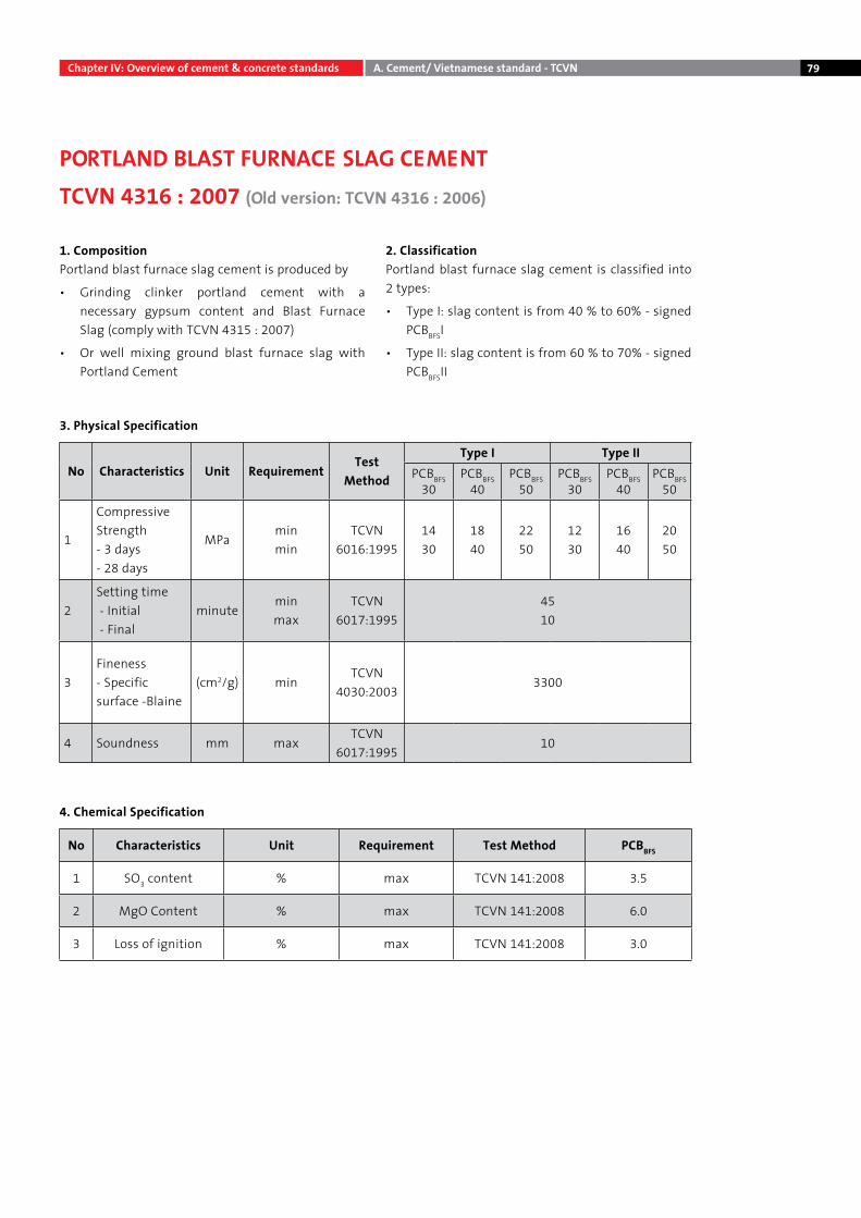
79
1. CompositionPortland blast furnace slag cement is produced by
• Grinding clinker portland cement with a necessary gypsum content and Blast Furnace Slag (comply with TCVN 4315 : 2007)
• Or well mixing ground blast furnace slag with Portland Cement
2. ClassificationPortland blast furnace slag cement is classified into 2 types:
• Type I: slag content is from 40 % to 60% - signed PCBBFSI
• Type II: slag content is from 60 % to 70% - signed PCBBFSII
Chapter IV: Overview of cement & concrete standards A. Cement/ Vietnamese standard - TCVN
PORTLAND BLAST FURNACE SLAG CEMENTTCVN 4316 : 2007 (Old version: TCVN 4316 : 2006)
No Characteristics Unit RequirementTest
Method
Type I Type IIPCBBFS
30PCBBFS
40PCBBFS
50PCBBFS
30PCBBFS
40PCBBFS
50
1
Compressive Strength - 3 days - 28 days
MPaminmin
TCVN 6016:1995
1430
1840
2250
1230
1640
2050
2Setting time - Initial - Final
minuteminmax
TCVN 6017:1995
4510
3Fineness- Specific surface -Blaine
(cm2/g) minTCVN
4030:20033300
4 Soundness mm maxTCVN
6017:199510
3. Physical Specification
No Characteristics Unit Requirement Test Method PCBBFS
1 SO3 content % max TCVN 141:2008 3.5
2 MgO Content % max TCVN 141:2008 6.0
3 Loss of ignition % max TCVN 141:2008 3.0
4. Chemical Specification
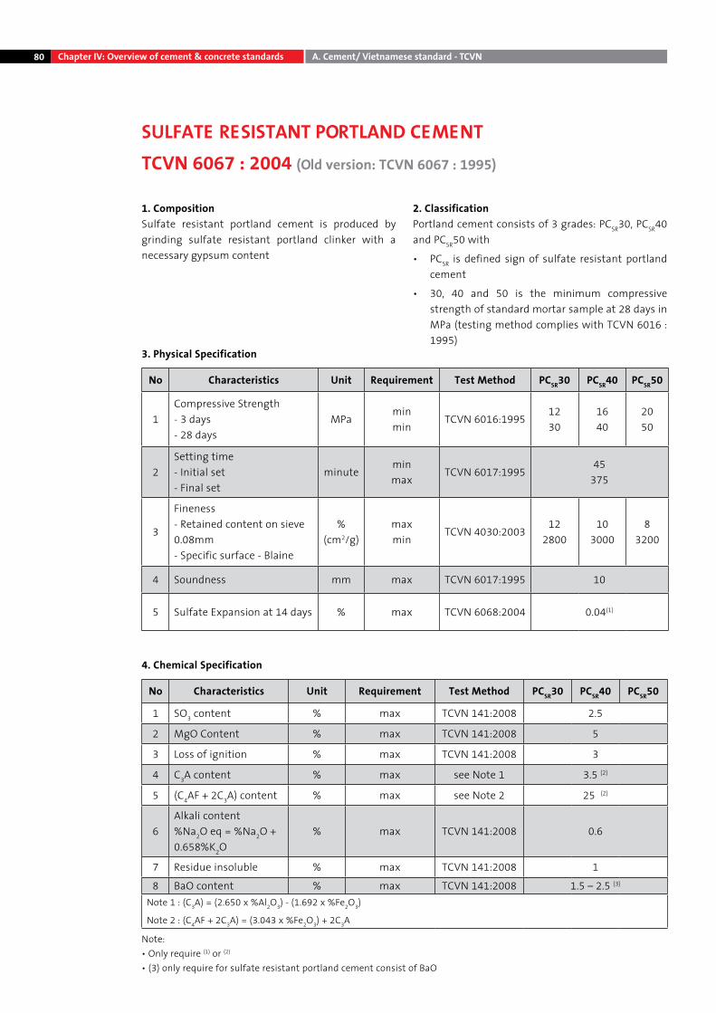
80
1. CompositionSulfate resistant portland cement is produced by grinding sulfate resistant portland clinker with a necessary gypsum content
2. ClassificationPortland cement consists of 3 grades: PCSR30, PCSR40 and PCSR50 with
• PCSR is defined sign of sulfate resistant portland cement
• 30, 40 and 50 is the minimum compressive strength of standard mortar sample at 28 days in MPa (testing method complies with TCVN 6016 : 1995)
Chapter IV: Overview of cement & concrete standards A. Cement/ Vietnamese standard - TCVN
4. Chemical Specification
SULFATE RESISTANT PORTLAND CEMENTTCVN 6067 : 2004 (Old version: TCVN 6067 : 1995)
3. Physical Specification
No Characteristics Unit Requirement Test Method PCSR30 PCSR40 PCSR50
1Compressive Strength - 3 days- 28 days
MPaminmin
TCVN 6016:19951230
1640
2050
2Setting time - Initial set- Final set
minuteminmax
TCVN 6017:199545
375
3
Fineness- Retained content on sieve 0.08mm- Specific surface - Blaine
%(cm2/g)
maxmin
TCVN 4030:200312
280010
30008
3200
4 Soundness mm max TCVN 6017:1995 10
5 Sulfate Expansion at 14 days % max TCVN 6068:2004 0.04(1)
No Characteristics Unit Requirement Test Method PCSR30 PCSR40 PCSR50
1 SO3 content % max TCVN 141:2008 2.5
2 MgO Content % max TCVN 141:2008 5
3 Loss of ignition % max TCVN 141:2008 3
4 C3A content % max see Note 1 3.5 (2)
5 (C4AF + 2C3A) content % max see Note 2 25 (2)
6Alkali content %Na2O eq = %Na2O + 0.658%K2O
% max TCVN 141:2008 0.6
7 Residue insoluble % max TCVN 141:2008 1
8 BaO content % max TCVN 141:2008 1.5 – 2.5 (3)
Note 1 : (C3A) = (2.650 x %Al2O3) - (1.692 x %Fe2O3)
Note 2 : (C4AF + 2C3A) = (3.043 x %Fe2O3) + 2C3A
Note:• Only require (1) or (2)
• (3) only require for sulfate resistant portland cement consist of BaO
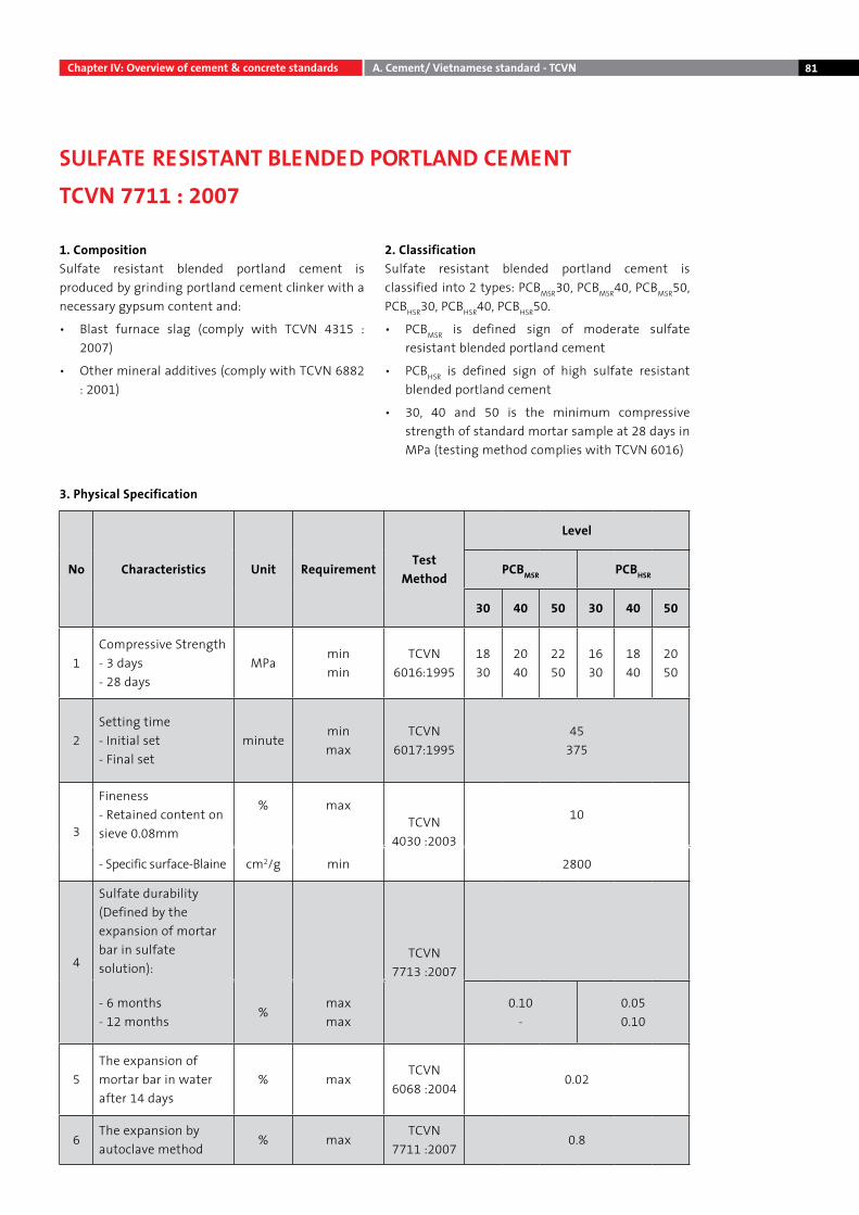
81
1. CompositionSulfate resistant blended portland cement is produced by grinding portland cement clinker with a necessary gypsum content and:
• Blast furnace slag (comply with TCVN 4315 : 2007)
• Other mineral additives (comply with TCVN 6882 : 2001)
2. ClassificationSulfate resistant blended portland cement is classified into 2 types: PCBMSR30, PCBMSR40, PCBMSR50, PCBHSR30, PCBHSR40, PCBHSR50.
• PCBMSR is defined sign of moderate sulfate resistant blended portland cement
• PCBHSR is defined sign of high sulfate resistant blended portland cement
• 30, 40 and 50 is the minimum compressive strength of standard mortar sample at 28 days in MPa (testing method complies with TCVN 6016)
Chapter IV: Overview of cement & concrete standards A. Cement/ Vietnamese standard - TCVN
SULFATE RESISTANT BLENDED PORTLAND CEMENTTCVN 7711 : 2007
No Characteristics Unit RequirementTest
Method
Level
PCBMSR PCBHSR
30 40 50 30 40 50
1Compressive Strength- 3 days- 28 days
MPaminmin
TCVN 6016:1995
1830
2040
2250
1630
1840
2050
2Setting time - Initial set- Final set
minuteminmax
TCVN 6017:1995
45375
3
Fineness- Retained content on sieve 0.08mm
% maxTCVN
4030 :2003
10
- Specific surface-Blaine cm2/g min 2800
4
Sulfate durability (Defined by the expansion of mortar bar in sulfate solution):
TCVN 7713 :2007
- 6 months- 12 months
%maxmax
0.10-
0.050.10
5The expansion of mortar bar in water after 14 days
% maxTCVN
6068 :20040.02
6The expansion by autoclave method
% maxTCVN
7711 :20070.8
3. Physical Specification
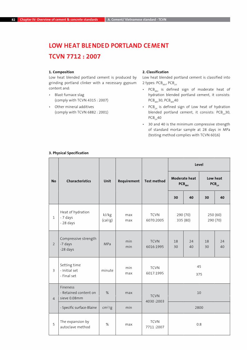
82
1. CompositionLow heat blended portland cement is produced by grinding portland clinker with a necessary gypsum content and:
• Blast furnace slag (comply with TCVN 4315 : 2007)
• Other mineral additives (comply with TCVN 6882 : 2001)
2. ClassificationLow heat blended portland cement is classified into 2 types: PCBMH, PCBLH
• PCBMH is defined sign of moderate heat of hydration blended portland cement, it consists: PCBMH30, PCBMH40
• PCBLH is defined sign of Low heat of hydration blended portland cement, it consists: PCBLH30, PCBLH40
• 30 and 40 is the minimum compressive strength of standard mortar sample at 28 days in MPa (testing method complies with TCVN 6016)
Chapter IV: Overview of cement & concrete standards A. Cement/ Vietnamese standard - TCVN
LOW HEAT BLENDED PORTLAND CEMENTTCVN 7712 : 2007
3. Physical Specification
No Characteristics Unit Requirement Test method
Level
Moderate heat PCBMH
Low heat PCBLH
30 40 30 40
1Heat of hydration- 7 days- 28 days
kJ/kg(cal/g)
maxmax
TCVN 6070:2005
290 (70)335 (80)
250 (60)290 (70)
2Compressive strength-7 days-28 days
MPaminmin
TCVN 6016:1995
1830
2440
1830
2440
3Setting time- Initial set - Final set
minuteminmax
TCVN 6017:1995
45
375
4
Fineness- Retained content on sieve 0.08mm
% maxTCVN
4030 :2003
10
- Specific surface-Blaine cm2/g min 2800
5The expansion by autoclave method
% maxTCVN
7711 :20070.8
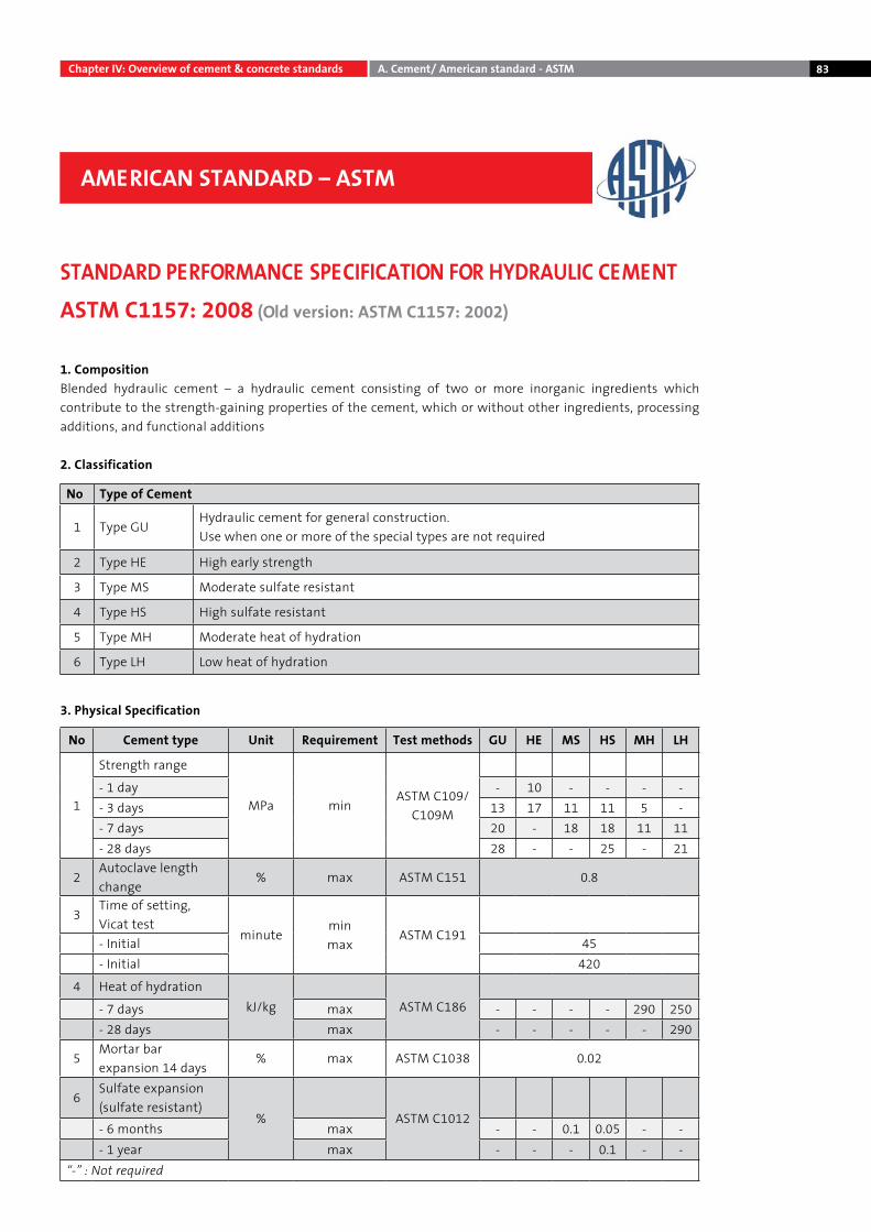
83
1. CompositionBlended hydraulic cement – a hydraulic cement consisting of two or more inorganic ingredients which contribute to the strength-gaining properties of the cement, which or without other ingredients, processing additions, and functional additions
2. Classification
No Type of Cement
1 Type GUHydraulic cement for general construction. Use when one or more of the special types are not required
2 Type HE High early strength
3 Type MS Moderate sulfate resistant
4 Type HS High sulfate resistant
5 Type MH Moderate heat of hydration
6 Type LH Low heat of hydration
AMERICAN STANDARD – ASTM
Chapter IV: Overview of cement & concrete standards A. Cement/ American standard - ASTM
STANDARD PERFORMANCE SPECIFICATION FOR HYDRAULIC CEMENTASTM C1157: 2008 (Old version: ASTM C1157: 2002)
No Cement type Unit Requirement Test methods GU HE MS HS MH LH
1
Strength range
MPa minASTM C109/
C109M
- 1 day - 10 - - - -- 3 days 13 17 11 11 5 -- 7 days 20 - 18 18 11 11- 28 days 28 - - 25 - 21
2Autoclave length change
% max ASTM C151 0.8
3Time of setting, Vicat test
minuteminmax
ASTM C191- Initial 45- Initial 420
4 Heat of hydrationkJ/kg ASTM C186- 7 days max - - - - 290 250
- 28 days max - - - - - 290
5Mortar bar expansion 14 days
% max ASTM C1038 0.02
6Sulfate expansion (sulfate resistant)
% ASTM C1012- 6 months max - - 0.1 0.05 - -- 1 year max - - - 0.1 - -
“-” : Not required
3. Physical Specification
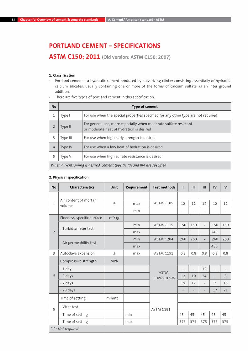
84
1. Classification• Portland cement – a hydraulic cement produced by pulverizing clinker consisting essentially of hydraulic
calcium silicates, usually containing one or more of the forms of calcium sulfate as an inter ground addition.
• There are five types of portland cement in this specification.
No Type of cement
1 Type I For use when the special properties specified for any other type are not required
2 Type IIFor general use, more especially when moderate sulfate resistant or moderate heat of hydration is desired
3 Type III For use when high early strength is desired
4 Type IV For use when a low heat of hydration is desired
5 Type V For use when high sulfate resistance is desired
When air-entraining is desired, cement type IA, IIA and IIIA are specified
2. Physical specification
No Characteristics Unit Requirement Test methods I II III IV V
1Air content of mortar, volume
% ASTM C185max 12 12 12 12 12
min - - - - -
2
Fineness, specific surface m2/kg
- Turbidiameter testmin ASTM C115 150 150 - 150 150
max 245
- Air permeability testmin ASTM C204 260 260 - 260 260
max 430
3 Autoclave expansion % max ASTM C151 0.8 0.8 0.8 0.8 0.8
4
Compressive strength MPa
ASTM C109/C109M
- 1 day - - 12 - -
- 3 days 12 10 24 - 8
- 7 days 19 17 - 7 15
- 28 days - - - 17 21
5
Time of setting minute
ASTM C191- Vicat test
- Time of setting min 45 45 45 45 45
- Time of setting max 375 375 375 375 375
“-” : Not required
Chapter IV: Overview of cement & concrete standards A. Cement/ American standard - ASTM
PORTLAND CEMENT – SPECIFICATIONS ASTM C150: 2011 (Old version: ASTM C150: 2007)
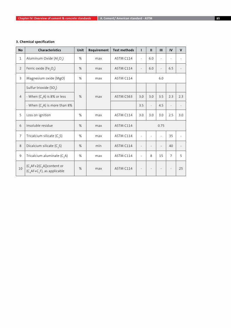
85
3. Chemical specification
No Characteristics Unit Requirement Test methods I II III IV V
1 Aluminum Oxide (Al2O3) % max ASTM C114 - 6.0 - - -
2 Ferric oxide (Fe2O3) % max ASTM C114 - 6.0 - 6.5 -
3 Magnesium oxide (MgO) % max ASTM C114 6.0
4
Sulfur trioxide (SO3)
% max- When (C3A) is 8% or less ASTM C563 3.0 3.0 3.5 2.3 2.3
- When (C3A) is more than 8% 3.5 - 4.5 - -
5 Loss on ignition % max ASTM C114 3.0 3.0 3.0 2.5 3.0
6 Insoluble residue % max ASTM C114 0.75
7 Tricalcium silicate (C3S) % max ASTM C114 - - - 35 -
8 Dicalcium silicate (C2S) % min ASTM C114 - - - 40 -
9 Tricalcium aluminate (C3A) % max ASTM C114 - 8 15 7 5
10(C4AF+2(C3A))content or (C4AF+C2F), as applicable
% max ASTM C114 - - - - 25
Chapter IV: Overview of cement & concrete standards A. Cement/ American standard - ASTM
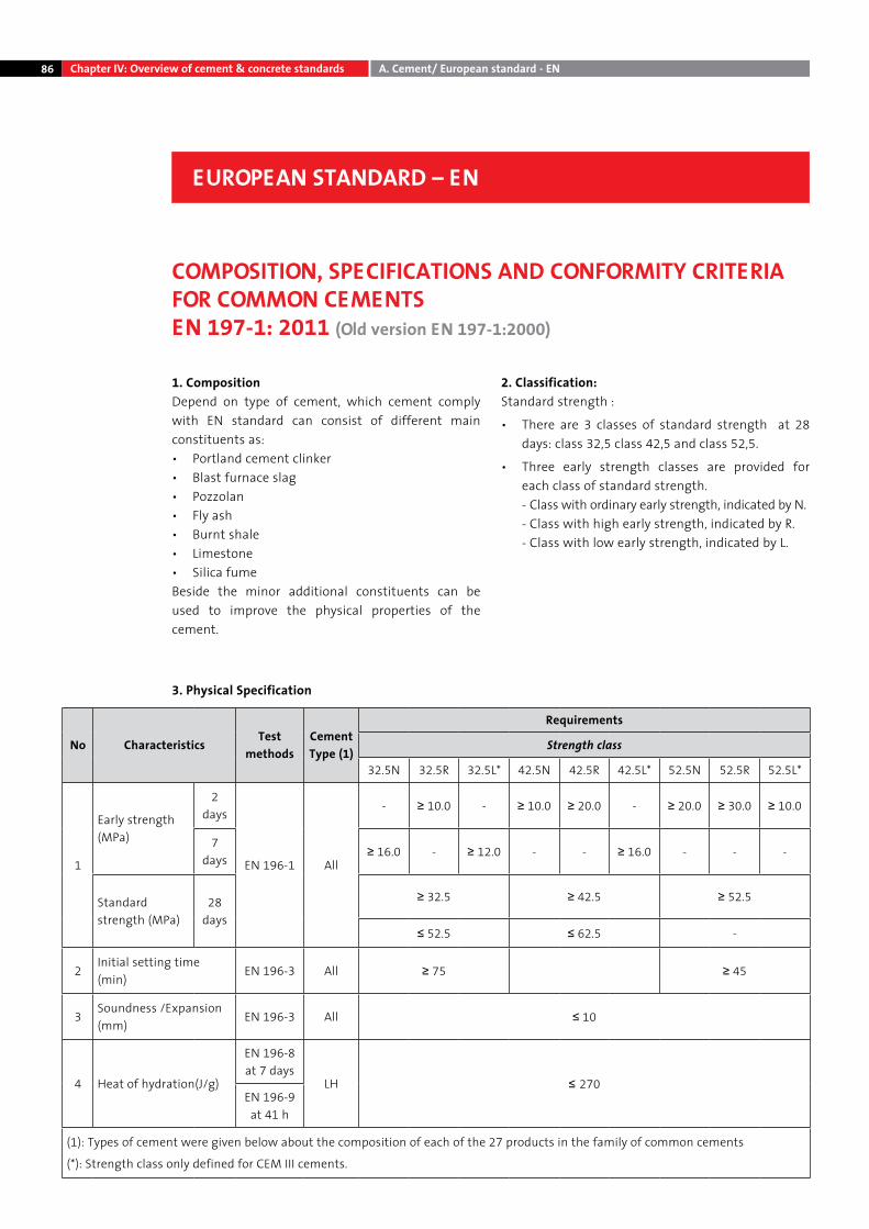
86
1. CompositionDepend on type of cement, which cement comply with EN standard can consist of different main constituents as:• Portland cement clinker• Blast furnace slag• Pozzolan• Fly ash• Burnt shale• Limestone• Silica fumeBeside the minor additional constituents can be used to improve the physical properties of the cement.
2. Classification:Standard strength :
• There are 3 classes of standard strength at 28 days: class 32,5 class 42,5 and class 52,5.
• Three early strength classes are provided for each class of standard strength.
- Class with ordinary early strength, indicated by N. - Class with high early strength, indicated by R. - Class with low early strength, indicated by L.
Chapter IV: Overview of cement & concrete standards A. Cement/ European standard - EN
EUROPEAN STANDARD – EN
COMPOSITION, SPECIFICATIONS AND CONFORMITY CRITERIA FOR COMMON CEMENTS EN 197-1: 2011 (Old version EN 197-1:2000)
No CharacteristicsTest
methodsCement Type (1)
Requirements
Strength class
32.5N 32.5R 32.5L* 42.5N 42.5R 42.5L* 52.5N 52.5R 52.5L*
1
Early strength (MPa)
2 days
EN 196-1 All
- ≥ 10.0 - ≥ 10.0 ≥ 20.0 - ≥ 20.0 ≥ 30.0 ≥ 10.0
7 days
≥ 16.0 - ≥ 12.0 - - ≥ 16.0 - - -
Standard strength (MPa)
28 days
≥ 32.5 ≥ 42.5 ≥ 52.5
≤ 52.5 ≤ 62.5 -
2Initial setting time (min)
EN 196-3 All ≥ 75 ≥ 45
3Soundness /Expansion (mm)
EN 196-3 All ≤ 10
4 Heat of hydration(J/g)
EN 196-8 at 7 days
LH ≤ 270EN 196-9
at 41 h
(1): Types of cement were given below about the composition of each of the 27 products in the family of common cements
(*): Strength class only defined for CEM III cements.
3. Physical Specification
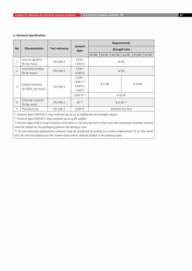
87
No Characteristics Test referenceCement
type
Requirements
Strength class
32.5N 32.5R 42.5N 42.5R 52.5N 52.5R
1Loss on ignition(% by mass)
EN 196-2CEM I
CEM III≤ 5%
2Insoluble residue(% by mass)
EN 196-2CEM I
CEM III≤ 5%
3Sulfate content(as %SO3 by mass)
EN 196-2
CEM ICEM II (1)
CEM IVCEM V
≤ 3.5% ≤ 4.0%
CEM III (2) ≤ 4.0%
4Chloride content(% by mass)
EN 196-2 All (3) ≤ 0.1% (4)
5 Pozzolanicity EN 196-5 CEM IV Satisfies the test(1) Cement type CEM II/B-T may containt up to 4.5 % sulfate for all strength classes.(2) Cement type CEM III/C may containt up to 4.5% sulfate.(3) Cement type CEM III may containt more than 0.1 % chloride but in that case the maximum chloride content shall be stated on the packaging and/or the delivery note.(4) For pre-stressing applications cements may be produced according to a lower requirement. If so, the value of 0.1% shall be replaced by this lower value which shall be stated in the delivery note.
Chapter IV: Overview of cement & concrete standards A. Cement/ European standard - EN
4. Chemical Specification
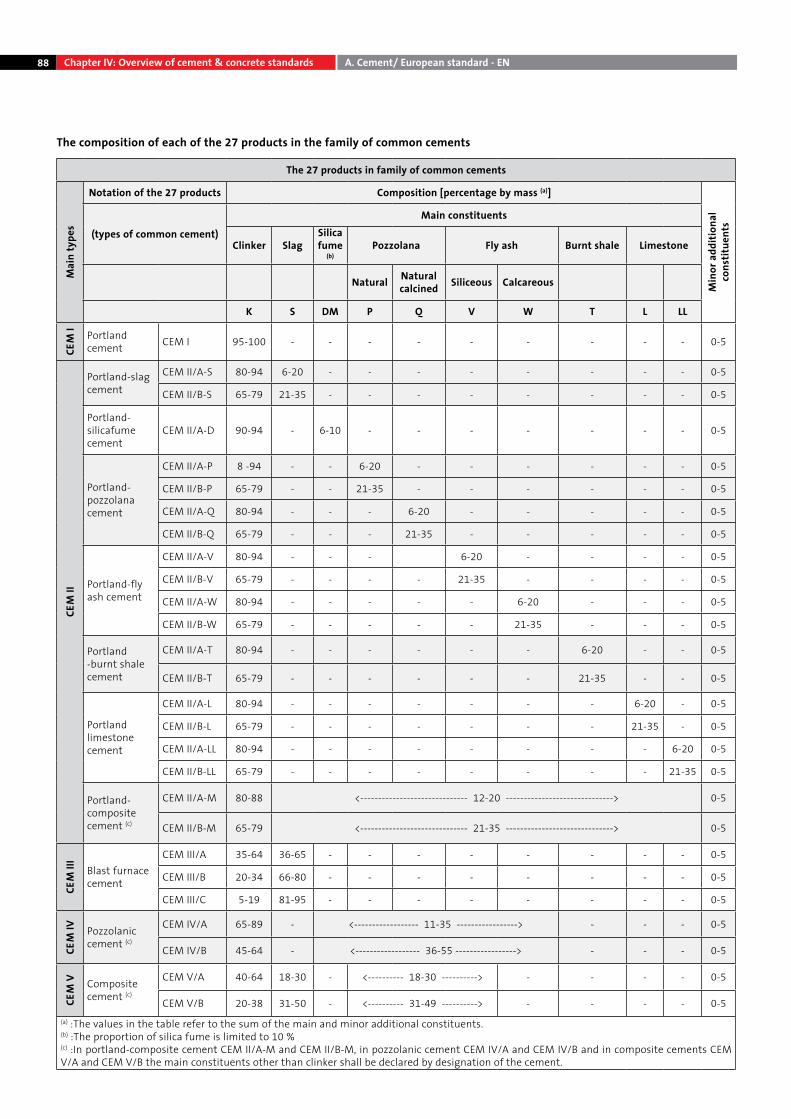
88 Chapter IV: Overview of cement & concrete standards A. Cement/ European standard - EN
The composition of each of the 27 products in the family of common cements
The 27 products in family of common cements
Mai
n ty
pes
Notation of the 27 products Composition [percentage by mass (a)]
Min
or a
dditi
onal
co
nstit
uent
s
(types of common cement)
Main constituents
Clinker SlagSilica fume
(b)Pozzolana Fly ash Burnt shale Limestone
Natural Natural calcined Siliceous Calcareous
K S DM P Q V W T L LL
CEM
I Portland cement CEM I 95-100 - - - - - - - - - 0-5
CEM
II
Portland-slag cement
CEM II/A-S 80-94 6-20 - - - - - - - - 0-5
CEM II/B-S 65-79 21-35 - - - - - - - - 0-5
Portland-silicafume cement
CEM II/A-D 90-94 - 6-10 - - - - - - - 0-5
Portland-pozzolana cement
CEM II/A-P 8 -94 - - 6-20 - - - - - - 0-5
CEM II/B-P 65-79 - - 21-35 - - - - - - 0-5
CEM II/A-Q 80-94 - - - 6-20 - - - - - 0-5
CEM II/B-Q 65-79 - - - 21-35 - - - - - 0-5
Portland-fly ash cement
CEM II/A-V 80-94 - - - 6-20 - - - - 0-5
CEM II/B-V 65-79 - - - - 21-35 - - - - 0-5
CEM II/A-W 80-94 - - - - - 6-20 - - - 0-5
CEM II/B-W 65-79 - - - - - 21-35 - - - 0-5
Portland -burnt shale cement
CEM II/A-T 80-94 - - - - - - 6-20 - - 0-5
CEM II/B-T 65-79 - - - - - - 21-35 - - 0-5
Portland limestone cement
CEM II/A-L 80-94 - - - - - - - 6-20 - 0-5
CEM II/B-L 65-79 - - - - - - - 21-35 - 0-5
CEM II/A-LL 80-94 - - - - - - - - 6-20 0-5
CEM II/B-LL 65-79 - - - - - - - - 21-35 0-5
Portland-composite cement (c)
CEM II/A-M 80-88 <------------------------------ 12-20 ------------------------------> 0-5
CEM II/B-M 65-79 <------------------------------ 21-35 ------------------------------> 0-5
CEM
III
Blast furnace cement
CEM III/A 35-64 36-65 - - - - - - - - 0-5
CEM III/B 20-34 66-80 - - - - - - - - 0-5
CEM III/C 5-19 81-95 - - - - - - - - 0-5
CEM
IV Pozzolanic cement (c)
CEM IV/A 65-89 - <------------------ 11-35 -----------------> - - - 0-5
CEM IV/B 45-64 - <------------------ 36-55 -----------------> - - - 0-5
CEM
V Composite cement (c)
CEM V/A 40-64 18-30 - <---------- 18-30 ----------> - - - - 0-5
CEM V/B 20-38 31-50 - <---------- 31-49 ----------> - - - - 0-5(a) :The values in the table refer to the sum of the main and minor additional constituents.(b) :The proportion of silica fume is limited to 10 %(c) :In portland-composite cement CEM II/A-M and CEM II/B-M, in pozzolanic cement CEM IV/A and CEM IV/B and in composite cements CEM V/A and CEM V/B the main constituents other than clinker shall be declared by designation of the cement.
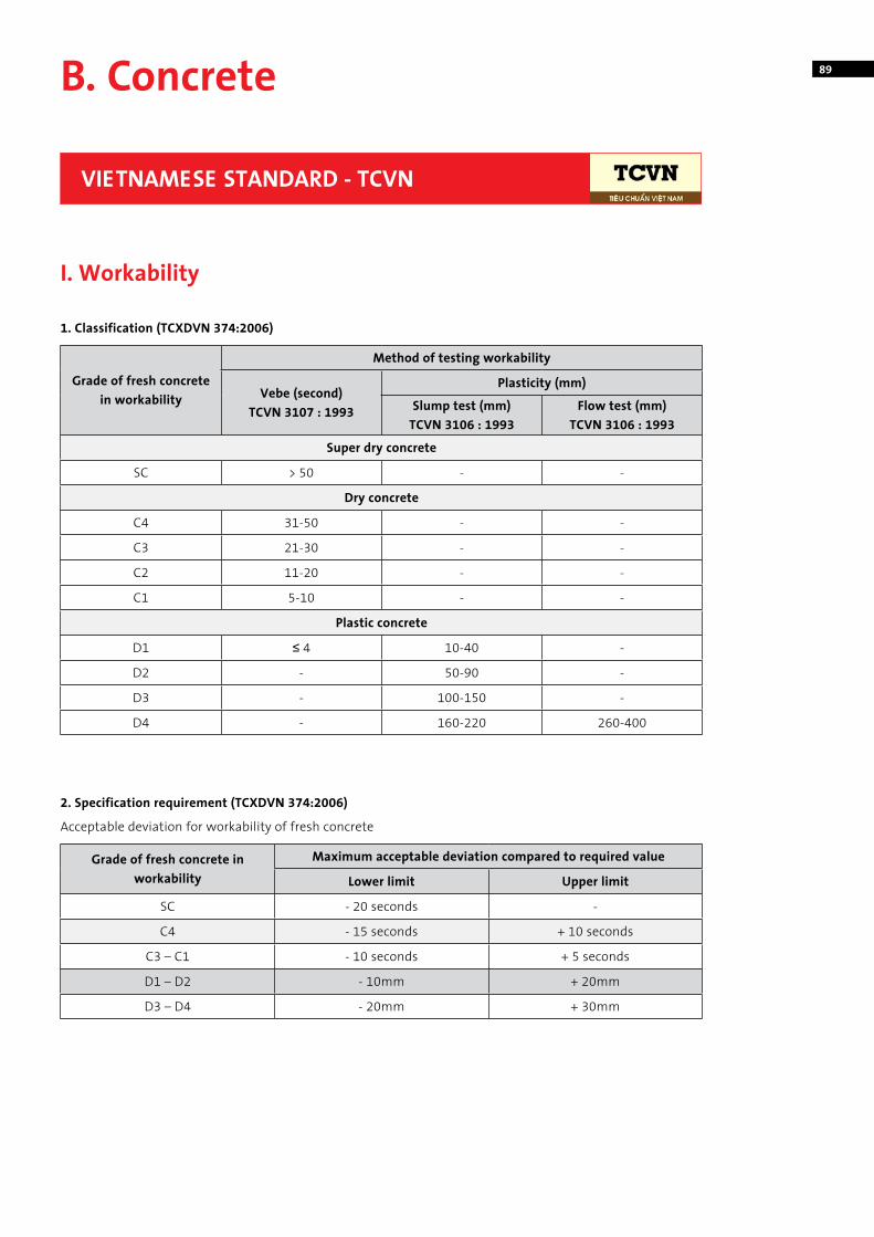
89B. Concrete
VIETNAMESE STANDARD - TCVN
I. Workability
1. Classification (TCXDVN 374:2006)
2. Specification requirement (TCXDVN 374:2006)
Grade of fresh concrete in workability
Method of testing workability
Vebe (second) TCVN 3107 : 1993
Plasticity (mm)
Slump test (mm) TCVN 3106 : 1993
Flow test (mm) TCVN 3106 : 1993
Super dry concrete
SC > 50 - -
Dry concrete
C4 31-50 - -
C3 21-30 - -
C2 11-20 - -
C1 5-10 - -
Plastic concrete
D1 ≤ 4 10-40 -
D2 - 50-90 -
D3 - 100-150 -
D4 - 160-220 260-400
Grade of fresh concrete in workability
Maximum acceptable deviation compared to required value
Lower limit Upper limit
SC - 20 seconds -
C4 - 15 seconds + 10 seconds
C3 – C1 - 10 seconds + 5 seconds
D1 – D2 - 10mm + 20mm
D3 – D4 - 20mm + 30mm
Acceptable deviation for workability of fresh concrete
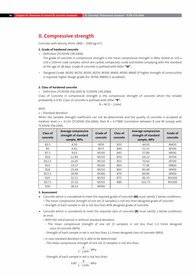
90 Chapter IV: Overview of cement & concrete standards B. Concrete/ Vietnamese standard - TCVN 374:2006
II. Compressive strength Concrete with density (from 1800 – 2500 kg/m3)
1. Grade of hardened concrete• Definition (TCXDVN 239:2006) The grade of concrete in compressive strength is the mean compressive strength in MPa, tested on 150 x
150 x 150mm cube samples, which are casted, compacted, cured and tested complying with the standard at the age of 28 days. Grade of concrete is prefixed with letter “M”.
• Designed Grade: M100, M150, M200, M250, M300, M400, M500, M600 (if higher strength of construction is required, higher design grade (Ex: M700, M800) is accepted.)
2. Class of hardened concrete• Definition (TCXDVN 356:2005 & TCXDVN 239:2006)Class of Concrete in compressive strength is the compressive strength of concrete which the reliable probability is 0.95. Class of concrete is prefixed with letter “B”.
B = M (1 – 1.64v)With:v – Standard deviation When the variable strength coefficient can not be determined and the quality of concrete is accepted at medium level, v = 0.135 (TCXDVN 356:2006), then B = 0.778M. Correlation between B and M comply with TCXDVN 356:2006:
Class of concrete
Average compressive strength of standard
sample, MPa
Grade of concrete
Class of concrete
Average compressive strength of standard
sample, MPa
Grade of concrete
B3.5 4.50 M50 B35 44.95 M450B5 6.42 M75 B40 51.37 M500
B7.5 9.63 M100 B45 57.80 M600B10 12.84 M150 B50 64.22 M700
B12.5 16.05 M150 B55 70.64 M700B15 19.27 M200 B60 77.06 M800B20 25.69 M250 B65 83.48 M900
B22.5 28.90 M300 B70 89.90 M900B25 32.11 M350 B75 96.33 M1000
B27.5 35.32 M350 B80 102.75 M1000B30 38.53 M400
3. Assessment• Concrete which is considered to meet the required grade of concrete (M) must satisfy 2 below conditions: • The mean compressive strength of one set (3 samples) is not less than designed grade of concrete • Strength of each sample in set is not less than 85% designed grade of concrete
• Concrete which is considered to meet the required class of concrete (B) must satisfy 2 below conditions at once:
• With the initial period or without standard deviation: - The mean compressive strength of one set (3 samples) is not less than 1.3 times designed
class of concrete (MPa) - Strength of each sample in set is not less than 1.1 times designed class of concrete (MPa)
• In case standard deviation (v) is able to be determined: - The mean compressive strength of one set (3 samples) is not less than:
- Strength of each sample in set is not less than:
MPaB
1 - 1,64v
MPa0.85 B1 - 1,64v
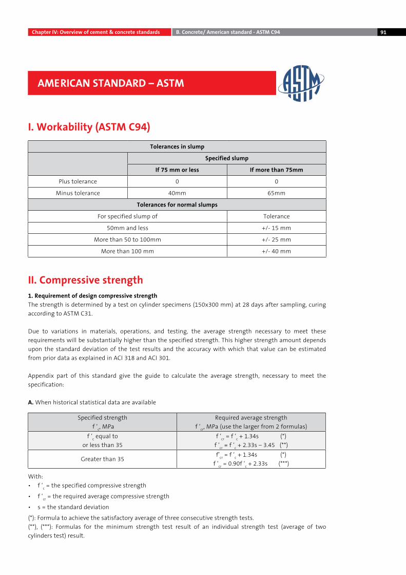
91Chapter IV: Overview of cement & concrete standards B. Concrete/ American standard - ASTM C94
AMERICAN STANDARD – ASTM
I. Workability (ASTM C94)
II. Compressive strength
Tolerances in slump
Specified slump
If 75 mm or less If more than 75mm
Plus tolerance 0 0
Minus tolerance 40mm 65mm
Tolerances for normal slumps
For specified slump of Tolerance
50mm and less +/- 15 mm
More than 50 to 100mm +/- 25 mm
More than 100 mm +/- 40 mm
1. Requirement of design compressive strengthThe strength is determined by a test on cylinder specimens (150x300 mm) at 28 days after sampling, curing according to ASTM C31.
Due to variations in materials, operations, and testing, the average strength necessary to meet these requirements will be substantially higher than the specified strength. This higher strength amount depends upon the standard deviation of the test results and the accuracy with which that value can be estimated from prior data as explained in ACI 318 and ACI 301.
Appendix part of this standard give the guide to calculate the average strength, necessary to meet the specification:
A. When historical statistical data are available
With:• f ‘c = the specified compressive strength
• f ‘cr = the required average compressive strength
• s = the standard deviation
(*): Formula to achieve the satisfactory average of three consecutive strength tests.(**), (***): Formulas for the minimum strength test result of an individual strength test (average of two cylinders test) result.
Specified strength f ‘c, MPa
Required average strengthf ‘cr, MPa (use the larger from 2 formulas)
f ‘c equal toor less than 35
f ‘cr = f ‘c + 1.34s (*)f ‘cr = f ‘c + 2.33s – 3.45 (**)
Greater than 35f’cr = f ‘c + 1.34s (*)
f ‘cr = 0.90f ‘c + 2.33s (***)
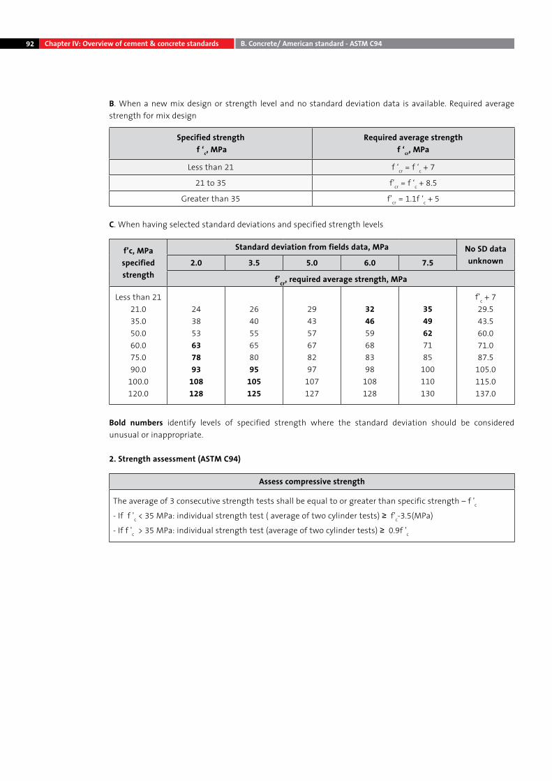
92
B. When a new mix design or strength level and no standard deviation data is available. Required average strength for mix design
Specified strength f ‘c, MPa
Required average strengthf ‘cr, MPa
Less than 21 f ‘cr = f ‘c + 7
21 to 35 f’cr = f ‘c + 8.5
Greater than 35 f’cr = 1.1f ‘c + 5
C. When having selected standard deviations and specified strength levels
f’c, MPaspecified strength
Standard deviation from fields data, MPa No SD dataunknown2.0 3.5 5.0 6.0 7.5
f’cr, required average strength, MPa
Less than 2121.035.050.060.075.090.0
100.0120.0
243853637893
108128
264055658095
105125
294357678297
107127
324659688398
108128
3549627185
100110130
f’c + 729.543.560.071.087.5
105.0115.0137.0
Bold numbers identify levels of specified strength where the standard deviation should be considered unusual or inappropriate.
2. Strength assessment (ASTM C94)
Assess compressive strength
The average of 3 consecutive strength tests shall be equal to or greater than specific strength – f 'c
- If f 'c < 35 MPa: individual strength test ( average of two cylinder tests) ≥ f'c-3.5(MPa)
- If f 'c > 35 MPa: individual strength test (average of two cylinder tests) ≥ 0.9f 'c
Chapter IV: Overview of cement & concrete standards B. Concrete/ American standard - ASTM C94
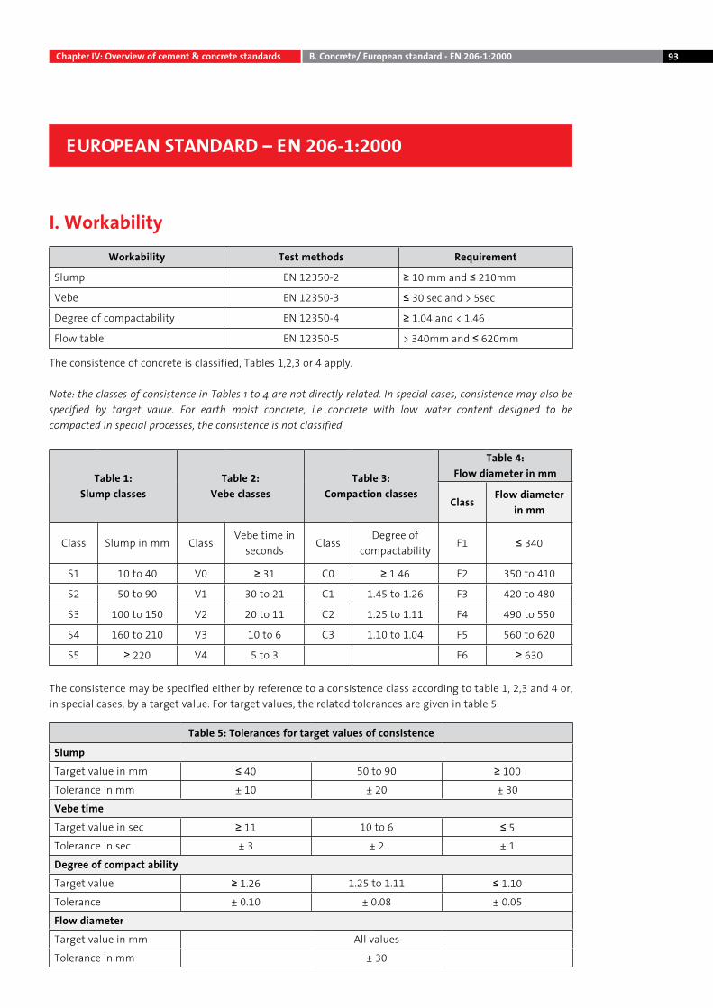
93Chapter IV: Overview of cement & concrete standards B. Concrete/ European standard - EN 206-1:2000
EUROPEAN STANDARD – EN 206-1:2000
I. WorkabilityWorkability Test methods Requirement
Slump EN 12350-2 ≥ 10 mm and ≤ 210mm
Vebe EN 12350-3 ≤ 30 sec and > 5sec
Degree of compactability EN 12350-4 ≥ 1.04 and < 1.46
Flow table EN 12350-5 > 340mm and ≤ 620mm
The consistence of concrete is classified, Tables 1,2,3 or 4 apply.
Note: the classes of consistence in Tables 1 to 4 are not directly related. In special cases, consistence may also be specified by target value. For earth moist concrete, i.e concrete with low water content designed to be compacted in special processes, the consistence is not classified.
Table 1: Slump classes
Table 2: Vebe classes
Table 3: Compaction classes
Table 4: Flow diameter in mm
ClassFlow diameter
in mm
Class Slump in mm ClassVebe time in
secondsClass
Degree of compactability
F1 ≤ 340
S1 10 to 40 V0 ≥ 31 C0 ≥ 1.46 F2 350 to 410
S2 50 to 90 V1 30 to 21 C1 1.45 to 1.26 F3 420 to 480
S3 100 to 150 V2 20 to 11 C2 1.25 to 1.11 F4 490 to 550
S4 160 to 210 V3 10 to 6 C3 1.10 to 1.04 F5 560 to 620
S5 ≥ 220 V4 5 to 3 F6 ≥ 630
The consistence may be specified either by reference to a consistence class according to table 1, 2,3 and 4 or, in special cases, by a target value. For target values, the related tolerances are given in table 5.
Table 5: Tolerances for target values of consistence
Slump
Target value in mm ≤ 40 50 to 90 ≥ 100
Tolerance in mm ± 10 ± 20 ± 30
Vebe time
Target value in sec ≥ 11 10 to 6 ≤ 5
Tolerance in sec ± 3 ± 2 ± 1
Degree of compact ability
Target value ≥ 1.26 1.25 to 1.11 ≤ 1.10
Tolerance ± 0.10 ± 0.08 ± 0.05
Flow diameter
Target value in mm All values
Tolerance in mm ± 30
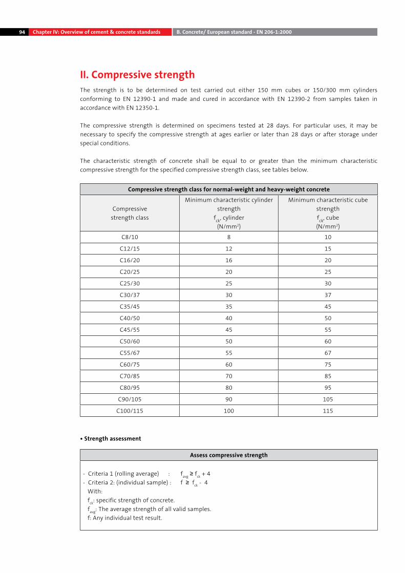
94 Chapter IV: Overview of cement & concrete standards B. Concrete/ European standard - EN 206-1:2000
II. Compressive strengthThe strength is to be determined on test carried out either 150 mm cubes or 150/300 mm cylinders conforming to EN 12390-1 and made and cured in accordance with EN 12390-2 from samples taken in accordance with EN 12350-1.
The compressive strength is determined on specimens tested at 28 days. For particular uses, it may be necessary to specify the compressive strength at ages earlier or later than 28 days or after storage under special conditions.
The characteristic strength of concrete shall be equal to or greater than the minimum characteristic compressive strength for the specified compressive strength class, see tables below.
Compressive strength class for normal-weight and heavy-weight concrete
Compressive strength class
Minimum characteristic cylinder strength
fck, cylinder(N/mm2)
Minimum characteristic cube strengthfck, cube(N/mm2)
C8/10 8 10
C12/15 12 15
C16/20 16 20
C20/25 20 25
C25/30 25 30
C30/37 30 37
C35/45 35 45
C40/50 40 50
C45/55 45 55
C50/60 50 60
C55/67 55 67
C60/75 60 75
C70/85 70 85
C80/95 80 95
C90/105 90 105
C100/115 100 115
• Strength assessment
Assess compressive strength
- Criteria 1 (rolling average) : favg ≥ fck + 4- Criteria 2: (individual sample) : f ≥ fck - 4 With: fck: specific strength of concrete. favg: The average strength of all valid samples. f: Any individual test result.
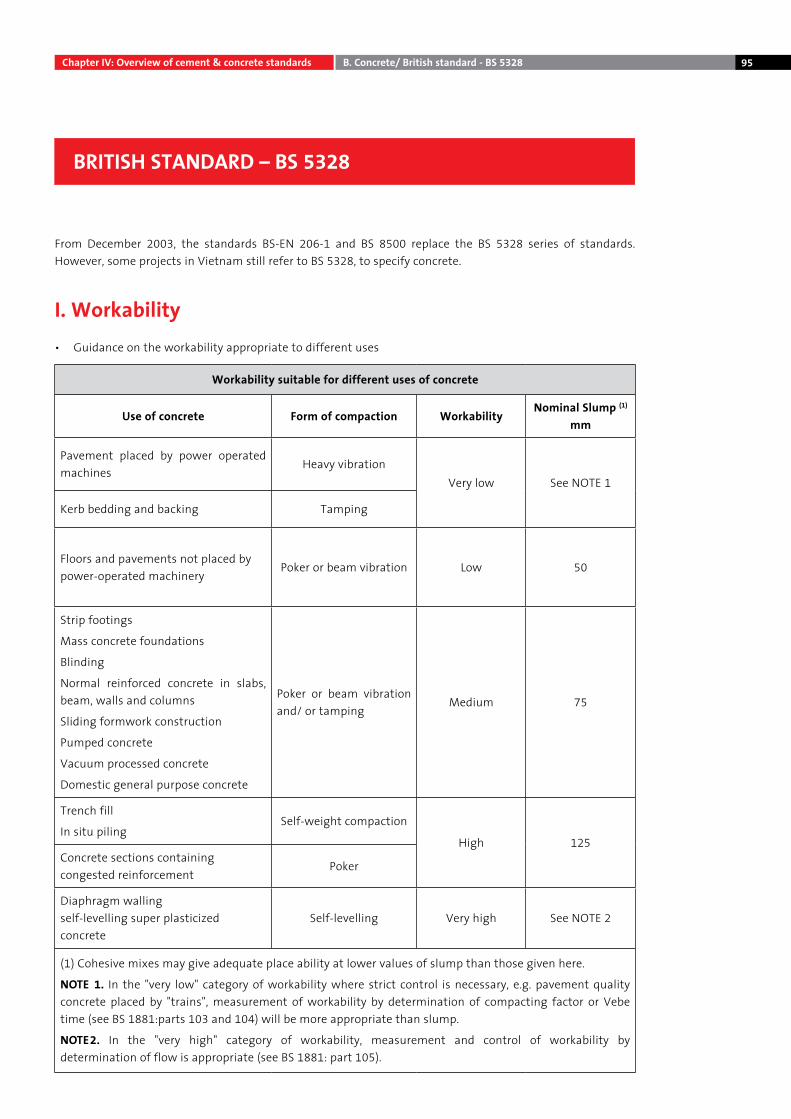
95Chapter IV: Overview of cement & concrete standards B. Concrete/ British standard - BS 5328
From December 2003, the standards BS-EN 206-1 and BS 8500 replace the BS 5328 series of standards. However, some projects in Vietnam still refer to BS 5328, to specify concrete.
I. Workability• Guidance on the workability appropriate to different uses
Workability suitable for different uses of concrete
Use of concrete Form of compaction WorkabilityNominal Slump (1)
mm
Pavement placed by power operated machines
Heavy vibrationVery low See NOTE 1
Kerb bedding and backing Tamping
Floors and pavements not placed bypower-operated machinery
Poker or beam vibration Low 50
Strip footings
Mass concrete foundations
Blinding
Normal reinforced concrete in slabs, beam, walls and columns
Sliding formwork construction
Pumped concrete
Vacuum processed concrete
Domestic general purpose concrete
Poker or beam vibration and/ or tamping
Medium 75
Trench fill
In situ pilingSelf-weight compaction
High 125Concrete sections containing congested reinforcement
Poker
Diaphragm wallingself-levelling super plasticized concrete
Self-levelling Very high See NOTE 2
(1) Cohesive mixes may give adequate place ability at lower values of slump than those given here.
NOTE 1. In the "very low" category of workability where strict control is necessary, e.g. pavement quality concrete placed by "trains", measurement of workability by determination of compacting factor or Vebe time (see BS 1881:parts 103 and 104) will be more appropriate than slump.
NOTE2. In the "very high" category of workability, measurement and control of workability by determination of flow is appropriate (see BS 1881: part 105).
BRITISH STANDARD – BS 5328
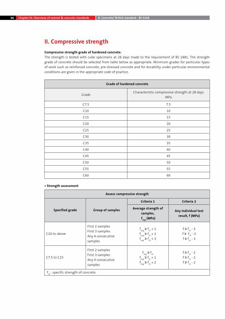
96 Chapter IV: Overview of cement & concrete standards B. Concrete/ British standard - BS 5328
II. Compressive strengthCompressive strength grade of hardened concrete:The strength is tested with cube specimens at 28 days made to the requirement of BS 1881. The strength grade of concrete should be selected from table below as appropriate. Minimum grades for particular types of work such as reinforced concrete, pre-stressed concrete and for durability under particular environmental conditions are given in the appropriate code of practice.
Grade of hardened concrete
GradeCharacteristic compressive strength at 28 days
MPa
C7.5 7.5
C10 10
C15 15
C20 20
C25 25
C30 30
C35 35
C40 40
C45 45
C50 50
C55 55
C60 60
• Strength assessment
Assess compressive strength
Specified grade Group of samples
Criteria 1 Criteria 2
Average strength of samples,
favg (MPa)
Any individual test result, f (MPa)
C20 to above
First 2 samplesFirst 3 samplesAny 4 consecutivesamples
favg ≥ fck + 1favg ≥ fck + 2favg ≥ fck + 3
f ≥ fck - 3f ≥ fck - 3f ≥ fck - 3
C7.5 to C15
First 2 samplesFirst 3 samplesAny 4 consecutive samples
favg ≥ fck
favg ≥ fck + 1favg ≥ fck + 2
f ≥ fck - 2f ≥ fck - 2f ≥ fck - 2
fck : specific strength of concrete.
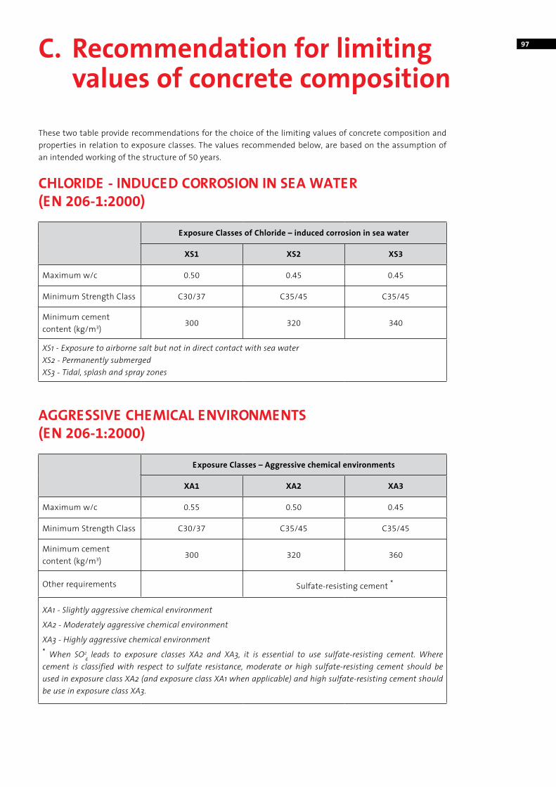
97
These two table provide recommendations for the choice of the limiting values of concrete composition and properties in relation to exposure classes. The values recommended below, are based on the assumption of an intended working of the structure of 50 years.
CHLORIDE - INDUCED CORROSION IN SEA WATER (EN 206-1:2000)
Exposure Classes of Chloride – induced corrosion in sea water
XS1 XS2 XS3
Maximum w/c 0.50 0.45 0.45
Minimum Strength Class C30/37 C35/45 C35/45
Minimum cementcontent (kg/m3)
300 320 340
XS1 - Exposure to airborne salt but not in direct contact with sea waterXS2 - Permanently submergedXS3 - Tidal, splash and spray zones
AGGRESSIVE CHEMICAL ENVIRONMENTS (EN 206-1:2000)
Exposure Classes – Aggressive chemical environments
XA1 XA2 XA3
Maximum w/c 0.55 0.50 0.45
Minimum Strength Class C30/37 C35/45 C35/45
Minimum cementcontent (kg/m3)
300 320 360
Other requirements Sulfate-resisting cement *
XA1 - Slightly aggressive chemical environment
XA2 - Moderately aggressive chemical environment
XA3 - Highly aggressive chemical environment* When SO2
4 leads to exposure classes XA2 and XA3, it is essential to use sulfate-resisting cement. Where cement is classified with respect to sulfate resistance, moderate or high sulfate-resisting cement should be used in exposure class XA2 (and exposure class XA1 when applicable) and high sulfate-resisting cement should be use in exposure class XA3.
C. Recommendation for limiting values of concrete composition
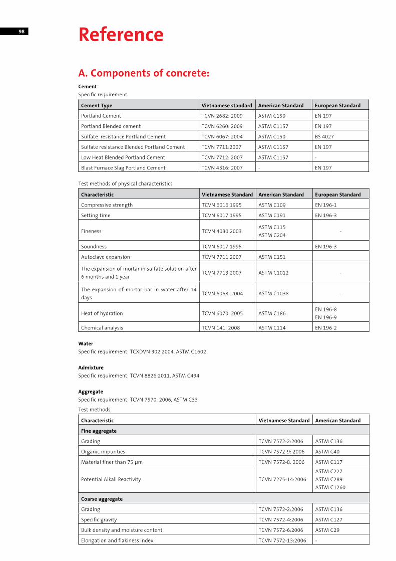
98
A. Components of concrete:CementSpecific requirement
Cement Type Vietnamese standard American Standard European Standard
Portland Cement TCVN 2682: 2009 ASTM C150 EN 197
Portland Blended cement TCVN 6260: 2009 ASTM C1157 EN 197
Sulfate resistance Portland Cement TCVN 6067: 2004 ASTM C150 BS 4027
Sulfate resistance Blended Portland Cement TCVN 7711:2007 ASTM C1157 EN 197
Low Heat Blended Portland Cement TCVN 7712: 2007 ASTM C1157 -
Blast Furnace Slag Portland Cement TCVN 4316: 2007 - EN 197
Test methods of physical characteristics
Characteristic Vietnamese Standard American Standard European Standard
Compressive strength TCVN 6016:1995 ASTM C109 EN 196-1
Setting time TCVN 6017:1995 ASTM C191 EN 196-3
Fineness TCVN 4030:2003ASTM C115ASTM C204
-
Soundness TCVN 6017:1995 EN 196-3
Autoclave expansion TCVN 7711:2007 ASTM C151
The expansion of mortar in sulfate solution after 6 months and 1 year
TCVN 7713:2007 ASTM C1012 -
The expansion of mortar bar in water after 14 days
TCVN 6068: 2004 ASTM C1038 -
Heat of hydration TCVN 6070: 2005 ASTM C186EN 196-8EN 196-9
Chemical analysis TCVN 141: 2008 ASTM C114 EN 196-2
WaterSpecific requirement: TCXDVN 302:2004, ASTM C1602
Admixture Specific requirement: TCVN 8826:2011, ASTM C494
AggregateSpecific requirement: TCVN 7570: 2006, ASTM C33
Test methods
Characteristic Vietnamese Standard American Standard
Fine aggregate
Grading TCVN 7572-2:2006 ASTM C136
Organic impurities TCVN 7572-9: 2006 ASTM C40
Material finer than 75 μm TCVN 7572-8: 2006 ASTM C117
Potential Alkali Reactivity TCVN 7275-14:2006ASTM C227ASTM C289ASTM C1260
Coarse aggregate
Grading TCVN 7572-2:2006 ASTM C136
Specific gravity TCVN 7572-4:2006 ASTM C127
Bulk density and moisture content TCVN 7572-6:2006 ASTM C29
Elongation and flakiness index TCVN 7572-13:2006 -
Reference
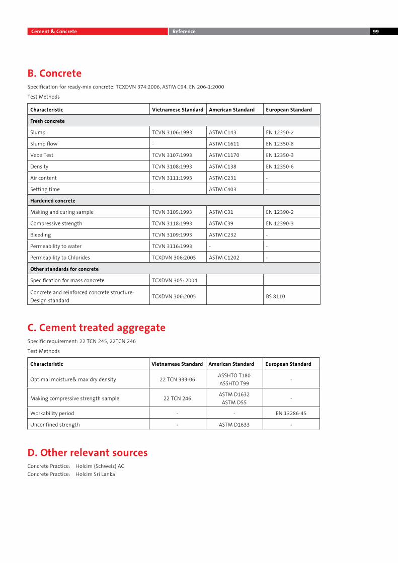
99
B. ConcreteSpecification for ready-mix concrete: TCXDVN 374:2006, ASTM C94, EN 206-1:2000
Test Methods
Characteristic Vietnamese Standard American Standard European Standard
Fresh concrete
Slump TCVN 3106:1993 ASTM C143 EN 12350-2
Slump flow - ASTM C1611 EN 12350-8
Vebe Test TCVN 3107:1993 ASTM C1170 EN 12350-3
Density TCVN 3108:1993 ASTM C138 EN 12350-6
Air content TCVN 3111:1993 ASTM C231 -
Setting time - ASTM C403 -
Hardened concrete
Making and curing sample TCVN 3105:1993 ASTM C31 EN 12390-2
Compressive strength TCVN 3118:1993 ASTM C39 EN 12390-3
Bleeding TCVN 3109:1993 ASTM C232 -
Permeability to water TCVN 3116:1993 - -
Permeability to Chlorides TCXDVN 306:2005 ASTM C1202 -
Other standards for concrete
Specification for mass concrete TCXDVN 305: 2004
Concrete and reinforced concrete structure- Design standard
TCXDVN 306:2005 BS 8110
C. Cement treated aggregateSpecific requirement: 22 TCN 245, 22TCN 246
Test Methods
Characteristic Vietnamese Standard American Standard European Standard
Optimal moisture& max dry density 22 TCN 333-06ASSHTO T180ASSHTO T99
-
Making compressive strength sample 22 TCN 246ASTM D1632
ASTM D55-
Workability period - - EN 13286-45
Unconfined strength - ASTM D1633 -
D. Other relevant sourcesConcrete Practice: Holcim (Schweiz) AGConcrete Practice: Holcim Sri Lanka
Cement & Concrete Reference
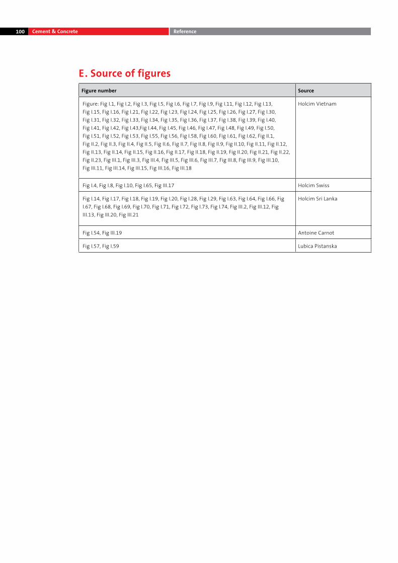
100
E. Source of figuresFigure number Source
Figure: Fig I.1, Fig I.2, Fig I.3, Fig I.5, Fig I.6, Fig I.7, Fig I.9, Fig I.11, Fig I.12, Fig I.13, Fig I.15, Fig I.16, Fig I.21, Fig I.22, Fig I.23, Fig I.24, Fig I.25, Fig I.26, Fig I.27, Fig I.30, Fig I.31, Fig I.32, Fig I.33, Fig I.34, Fig I.35, Fig I.36, Fig I.37, Fig I.38, Fig I.39, Fig I.40, Fig I.41, Fig I.42, Fig I.43,Fig I.44, Fig I.45, Fig I.46, Fig I.47, Fig I.48, Fig I.49, Fig I.50, Fig I.51, Fig I.52, Fig I.53, Fig I.55, Fig I.56, Fig I.58, Fig I.60, Fig I.61, Fig I.62, Fig II.1, Fig II.2, Fig II.3, Fig II.4, Fig II.5, Fig II.6, Fig II.7, Fig II.8, Fig II.9, Fig II.10, Fig II.11, Fig II.12, Fig II.13, Fig II.14, Fig II.15, Fig II.16, Fig II.17, Fig II.18, Fig II.19, Fig II.20, Fig II.21, Fig II.22, Fig II.23, Fig III.1, Fig III.3, Fig III.4, Fig III.5, Fig III.6, Fig III.7, Fig III.8, Fig III.9, Fig III.10, Fig III.11, Fig III.14, Fig III.15, Fig III.16, Fig III.18
Holcim Vietnam
Fig I.4, Fig I.8, Fig I.10, Fig I.65, Fig III.17 Holcim Swiss
Fig I.14, Fig I.17, Fig I.18, Fig I.19, Fig I.20, Fig I.28, Fig I.29, Fig I.63, Fig I.64, Fig I.66, Fig I.67, Fig I.68, Fig I.69, Fig I.70, Fig I.71, Fig I.72, Fig I.73, Fig I.74, Fig III.2, Fig III.12, Fig III.13, Fig III.20, Fig III.21
Holcim Sri Lanka
Fig I.54, Fig III.19 Antoine Carnot
Fig I.57, Fig I.59 Lubica Pistanska
Cement & Concrete Reference

101

102

Holcim (Vietnam) Ltd.
Fideco Tower, 9th & 10th Floors81 - 85 Ham Nghi Street, District 1Ho Chi Minh City, VietnamPhone: +84 8 39149000Fax: +84 8 39149001
Email: [email protected] Website: www.holcim.com.vn
Printed on PEFC standard sustainable paper.
Publishing licence number: 97-2012/CXB/239/01/VHTT.