hollow shaft resolver - rgbautomatyka.pl · hollow shaft resolver catalog 1308215 issued 04-01...
TRANSCRIPT

Hollow Shaft Resolver
Catalog 1308215Issued 04-01
T h e Te c h n o l o g y C o m p a n y
HollowShaft - Englisch 18.04.2001 11:13 Uhr Seite 2

Tyco Electronics Growing to meet your electronic component and system needs
Tyco Electronics, the largest division of Tyco International Ltd., was established in September 1999 when Tyco merged with Elcon Products,Raychem and AMP, all acquired earlier the same year. Combined with further acquisitions such as the Electromechanical Components division of Siemens, the Electronic OEM division of Thomas & Betts, Critchley and others, Tyco Electronics is now the world’s largest passive componentsupplier, with product ranges in 21 passive and active product segments.
Recently, our capabilities expanded considerably with the acquisition of the Power Systems division of Lucent Technologies. This allows TycoElectronics to offer you high-quality AC-DC and DC-DC power solutions for a broad range of applications, from small power modules for laptopcomputers to very large stand-alone systems capable of handling up to 10,000 amperes.
Today, in addition to power systems, our product portfolio encompasses connector systems and application tooling, active and passive fiberopticdevices, wireless components (including ICs, radar sensors and complete communications systems), heat shrink products, PolySwitch circuitprotection devices, magnetic components, wire and cable systems, touchscreens, PC boards and backplanes, relays, sensors, electronic modules,battery packs, terminal blocks and switches. Our goal is to be the market leader in each of these segments.
A significant result of our continued growth and a real benefit to our customers is that Tyco Electronics’ technology leadership has become evenstronger. Our expertise and synergies in materials science, product design and process engineering, coupled with our network of well-trainedapplication engineers and sales representatives, allows us not only to provide superior customer service, but also to better assist you in makingyour next generation of products successful.
Call us – we’re ready to help.
Product and Machine Literature
Product and machine literature quick and easy by fax.
A wide range of products also requires an extensive literature stock. We can provide you with brochures, catalogs and flyers for every productprogram of your interest.
Our catalog service team supports you in selecting and ordering the appropriate catalog. To get product and application tooling catalogs quicklyand easily, please contact your local Tyco Electronics company.
Product Information Center (PIC)
You can rely on our PIC Team’s support.
Our experienced staff is an additional information source, and the team has been particularly trained to answer your technical questions.
To reach our PIC, please contact your local Tyco Electronics AMP company.
Tyco Electronics AMP @nline
Internet Homepage: http://www.tycoelectronics.comhttp://www.amp.com
Electronic Catalog in the Internet: http://connect.amp.com
To be close to our customers worldwide is an essential part of our success.
The Tyco Electronics AMP Website is more than merely an Internet-guide.It is an innovative and interactive source for application tips, product updateand technical information. This Website is available in eight languages. Withour StepSearch-Software you can easily surf through all of our product lines.
&Service
Global Commitment
HollowShaft - Englisch 18.04.2001 11:13 Uhr Seite 3

1
Gen
eral
Siz
e 15
Siz
e 21
Content
Page
General Description 2
General Terms 3
Overview of Standard Types 4
Hollow Shaft Resolver Size 15 5
Technical Data 5
Dimensioned drawing 6
V23401-D1001-B1.. 7
V23401-D1008-B1.. 3-speed 10
V23401-D1009-B1.. with low output impedance 13
V23401-S1001-B1.. 16
Hollow Shaft Resolver Size 21 19
Technical Data 19
Dimensioned drawing 20
V23401-T1002-B1.. / V23401-H1002-B1.. 3-speed 22
V23401-T1005-B1.. / V23401-H1005-B1.. 25
V23401-T1009-B1.. / V23401-H1009-B1.. with low output impedance 28
V23401-T2001-B2.. / V23401-H2001-B2.. 31
V23401-T2009-B2.. / V23401-H2009-B2.. with low output impedance 34
V23401-T2010-B2.. / V23401-H2010-B2.. 3-speed 37
V23401-T2014-B2.. / V23401-H2014-B2.. 4-speed 40
V23401-T2015-B2.. / V23401-H2015-B2.. 2-speed 43
V23401-U1016-B1.. 46
V23401-U2017-B2.. 49
V23401-U2020-B2.. 3-speed 52
Hohlwellen - Inhalt 04.04.2001 17:01 Uhr Seite 1
2
Hollow Shaft Resolver
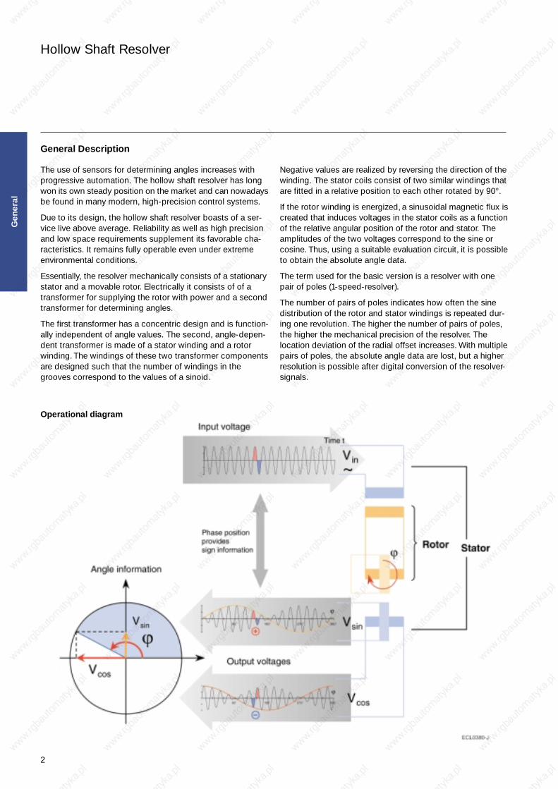
Negative values are realized by reversing the direction of thewinding. The stator coils consist of two similar windings thatare fitted in a relative position to each other rotated by 90°.
If the rotor winding is energized, a sinusoidal magnetic flux iscreated that induces voltages in the stator coils as a functionof the relative angular position of the rotor and stator. Theamplitudes of the two voltages correspond to the sine orcosine. Thus, using a suitable evaluation circuit, it is possibleto obtain the absolute angle data.
The term used for the basic version is a resolver with onepair of poles (1-speed-resolver).
The number of pairs of poles indicates how often the sinedistribution of the rotor and stator windings is repeated dur-ing one revolution. The higher the number of pairs of poles,the higher the mechanical precision of the resolver. Thelocation deviation of the radial offset increases. With multiplepairs of poles, the absolute angle data are lost, but a higherresolution is possible after digital conversion of the resolver-signals.
Operational diagram
Gen
eral
General Description
The use of sensors for determining angles increases withprogressive automation. The hollow shaft resolver has longwon its own steady position on the market and can nowadaysbe found in many modern, high-precision control systems.
Due to its design, the hollow shaft resolver boasts of a ser-vice live above average. Reliability as well as high precisionand low space requirements supplement its favorable cha-racteristics. It remains fully operable even under extremeenvironmental conditions.
Essentially, the resolver mechanically consists of a stationarystator and a movable rotor. Electrically it consists of of atransformer for supplying the rotor with power and a secondtransformer for determining angles.
The first transformer has a concentric design and is function-ally independent of angle values. The second, angle-depen-dent transformer is made of a stator winding and a rotorwinding. The windings of these two transformer componentsare designed such that the number of windings in the grooves correspond to the values of a sinoid.
Hohlwellen - Inhalt 04.04.2001 17:01 Uhr Seite 2

Hollow Shaft Resolver
3
Pairs of poles p (speed)The number of electrical sine and cosine cycles per mechanical revolution.
Residual voltage VresidualThe residual voltage is the actual value of the voltage remaining when VS1-S3 or VS2-S4 takes on the nominal value of zero.
Vresidual < 0.7 % of rT · VR1-R2
Angle error spread ∆ϕThe angle error spread is the deviation (unit: arcmin = ′ ) of the angle represented by the electrical signals from the correspond-ing actual mechanical angle.
∆ϕ = ϕel – ϕmech · p with p = pairs of poles
Applicable definition: the angle error spread lies within ± n arc minutes in any angular position of the specified band.
DC resistance valuesThe ohmic resistance values are based on an ambient temperature of 22 °C and change with temperature by 0.39 % / K.
Phase shift ψThe phase shift ψ is the lag between the input signal and output signal.
Transformation ratio rTThe transformation ratio rT is the ratio between the input voltage and the maximum output voltage.
rT = VS1-S3 max / VR1-R2
rT = VS2-S4 max / VR1-R2
Impedance values ZRO; ZRS; ZSO; ZSSThe impedance values are the ac resistance values and depend on the frequency. Especially ZSO is the value relevant for theoutput capability of the resolver, while ZRS is decisive for the load on the energizing signal source.
General Terms
Gen
eral
Hohlwellen - Inhalt 04.04.2001 17:01 Uhr Seite 3

4
Hollow Shaft Resolver
Overview of Standard Types
SizePairs
of poles(speed)
Housing material
Trans-formation
ratioNotes
Gen
eral
Angular error range ±4′ ±6′ ±7′ ±8′ ±10′ ±15′ ±20′
Ordering number ..33 ..10 ..02 ..09 ..01 ..22 ..14
1 CrNi-steel V23401-D1001-B1.. X X X X 0.50
15,3 CrNi-steel V23401-D1008-B1.. X X X X 0.50 3-speed
1 CrNi-steel V23401-D1009-B1.. X X X X 0.50with low output
impedance
1 CrMo-steel V23401-S1001-B1.. X X X X 0.50
3Aluminum V23401-T1002-B1..CrNi-steel V23401-H1002-B1..
X X X X 0.50 3-speed
1Aluminum V23401-T1005-B1..CrNi-steel V23401-H1005-B1..
X X X X 0.50
1Aluminum V23401-T1009-B1..
X X X X 0.50with low output
CrNi-steel V23401-H1009-B1.. impedance
1Aluminum V23401-T2001-B2..CrNi-steel V23401-H2001-B2..
X X X X 0.50
1Aluminum V23401-T2009-B2..
X X X X 0.50with low output
CrNi-steel V23401-H2009-B2.. impedance
21, 3Aluminum V23401-T2010-B2..CrNi-steel V23401-H2010-B2..
X X X X 0.46 3-speed
4Aluminum V23401-T2014-B2..CrNi-steel V23401-H2014-B2..
X X X X 0.46 4-speed
2Aluminum V23401-T2015-B2..CrNi-steel V23401-H2015-B2..
X X X X 0.50 2-speed
1 CrMo-steel V23401-U1016-B1.. X X X X 0.50
1 CrMo-steel V23401-U2017-B2.. X X X 0.50
3 CrMo-steel V23401-U2020-B2.. X X X 0.46 3-speed
Hohlwellen - Inhalt 04.04.2001 17:01 Uhr Seite 4

5
Hollow Shaft Resolver Size 15 V23401-D1… V23401-S1…
High-voltage test Windings to housing 250 VAC, 50 Hz Windings to each other 250 VAC, 50 Hz
Insulation resistance Windings to housing and Rinsulation > 50 MΩ at 500 VDCwindings to each other
Operating temperature range –55 °C ... +150 °C
Weight V23401-D... approx. 90 g V23401-S... approx. 90 g
Momentum of inertia of the rotor approx. 20 g · cm2
Maximum rational speed 20000 rpm
Maximum angular acceleration 150000 rad/s2
Torsional strength of rotor components 0.25 Nm
Shock resistance (11 ms sine) 1000 m/s2
Vibration fatigue limit (0 ... 2 kHz) 200 m/s2
Permissible radial runout 0.075 mm (see Dimensioned drawing: Note 1)
Permissible axial offset ± 0.25 mm(see Dimensioned drawing: Note 2)
Electrical and thermal limits
Mechanical data
Function
VS1-S3 = +rT · VR1-R2 · cos(p · α) VS2-S4 = +rT · VR1-R2 · sin(p · α)
p = pairs of poles
This function applies to the clockwise rotationof the rotor when looking at the (grooveless)transformer component from the top.
Siz
e 15
(yellow / white resp.
black / white)
(red / white)
(yellow)
(blue)
(red)
(black)
Transfer function
Hohlwellen - Inhalt 04.04.2001 17:01 Uhr Seite 5

6
Hollow Shaft Resolver Size 15 V23401-D1… V23401-S1…
Dimensioned drawing
Siz
e 15
AWG 28, Teflon-coatedL = 300 mm
1) Total runout when installed
2) Axial offset
Hohlwellen - Inhalt 04.04.2001 17:01 Uhr Seite 6

7
Hollow Shaft Resolver Size 15 V23401-D1001-B1..
Angular error spread ∆ϕ Ordering code ± 20′ V23401-D1001-B114 ± 15′ V23401-D1001-B122 ± 10′ V23401-D1001-B101 ± 7′ V23401-D1001-B102
Residual voltage Vresidual 25 mV at VR1-R2 = 7 V
Electrical data at 22 °C.
Transfer function
Pairs of poles p p = 1
Transformation ratio rT
rT = VS1-S3 max / VR1-R2
rT = VS2-S4 max / VR1-R2
ü = 0.5 ± 10 % within 4 ... 20 kHz = 0.5 ± 5 % at 5 kHz
Phase shift ψ
VR1-R2(t) = VR1-R2 max · sin(2 · π · f · t)
VS1-S3(t) = VS1-S3 max · sin(2 · π · f · t - ψ)
for –90° < α < +90°
Tolerance: ± 5°
Housing CrNi-steel
Siz
e 15
Electrical error / Ordering information
Hohlwellen - Inhalt 04.04.2001 17:01 Uhr Seite 7
8
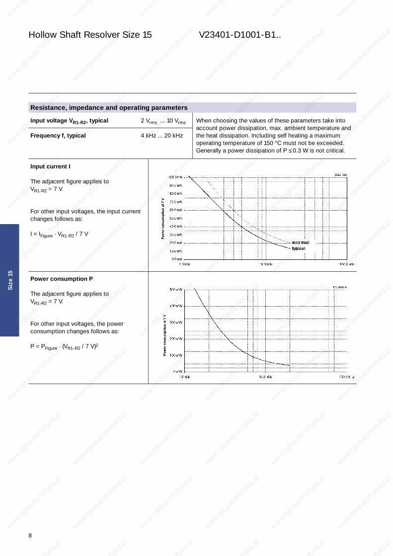
When choosing the values of these parameters take intoaccount power dissipation, max. ambient temperature andthe heat dissipation. Including self heating a maximum operating temperature of 150 °C must not be exceeded. Generally a power dissipation of P ≤ 0.3 W is not critical.
Hollow Shaft Resolver Size 15 V23401-D1001-B1..
Input voltage VR1-R2, typical 2 Vrms ... 10 Vrms
Frequency f, typical 4 kHz ... 20 kHz
Input current I
The adjacent figure applies to VR1-R2 = 7 V.
For other input voltages, the input current changes follows as:
I = IFigure · VR1-R2 / 7 V
Power consumption P
The adjacent figure applies to VR1-R2 = 7 V.
For other input voltages, the power consumption changes follows as:
P = PFigure · (VR1-R2 / 7 V)2
Siz
e 15
Resistance, impedance and operating parameters
Hohlwellen - Inhalt 04.04.2001 17:01 Uhr Seite 8

9
Hollow Shaft Resolver Size 15 V23401-D1001-B1..
Resistance, impedance and operating parameters (continued)
DC resistance
The ohmic resistance values are based on an RR1-R2 = 46 Ωambient temperature of 22 °C and change with RS1-S3 = RS2-S4 = 63 Ωtemperature by 0.39 % / K Tolerance: ± 10 %
Input impedance
Tolerance: ± 15 % Tolerance: ± 15 %ZRO ... Impedance between R1 and R2 with open outputs ZRS ... Impedance between R1 and R2 with short circuits
between S1 and S3 as well as between S2 and S4
Output impedance
Tolerance: ± 15 % Tolerance: ± 15 %ZSO ... Impedance between S2 and S4 in a position of 0° ZSS ... Impedance between S1 and S3 in a position of 0°
(minimal coupling) with open outputs (max. coupling) with short circuits between R1 and R2
Inductance L
L = X / (2 · π · f) LRO = 4.4 mHat f = 10 kHz LSS = 4.1 mH
Siz
e 15
Hohlwellen - Inhalt 04.04.2001 17:01 Uhr Seite 9

10
Hollow Shaft Resolver Size 15 V23401-D1008-B1.. 3-speed
Housing CrNi-steel
Siz
e 15
Angular error spread ∆ϕ Ordering code ± 20′ V23401-D1008-B114 ± 15′ V23401-D1008-B122 ± 10′ V23401-D1008-B101 ± 7′ V23401-D1008-B102
Residual voltage Vresidual 14 mV at VR1-R2 = 4 V
Electrical data at 22 °C.
Transfer function
Pairs of poles p p = 3
Transformation ratio rT
rT = VS1-S3 max / VR1-R2
rT = VS2-S4 max / VR1-R2
ü = 0.5 ± 10 % within 5 ... 20 kHz = 0.5 ± 5 % at 10 kHz
Phase shift ψ
VR1-R2(t) = VR1-R2 max · sin(2 · π · f · t)
VS1-S3(t) = VS1-S3 max · sin(2 · π · f · t - ψ)
for –90° < α < +90°
Tolerance: ± 5°
Electrical error / Ordering information
Hohlwellen - Inhalt 04.04.2001 17:01 Uhr Seite 10

11
Hollow Shaft Resolver Size 15 V23401-D1008-B1.. 3-speed
Siz
e 15
When choosing the values of these parameters take intoaccount power dissipation, max. ambient temperature andthe heat dissipation. Including self heating a maximum operating temperature of 150 °C must not be exceeded. Generally a power dissipation of P ≤ 0.3 W is not critical.
Input voltage VR1-R2, typical 2 Vrms ... 8 Vrms
Frequency f, typical 5 kHz ... 20 kHz
Input current I
The adjacent figure applies to VR1-R2 = 4 V.
For other input voltages, the input current changes follows as:
I = IFigure · VR1-R2 / 4 V
Power consumption P
The adjacent figure applies to VR1-R2 = 4 V.
For other input voltages, the power consumption changes follows as:
P = PFigure · (VR1-R2 / 4 V)2
Resistance, impedance and operating parameters
Hohlwellen - Inhalt 04.04.2001 17:01 Uhr Seite 11

12
Hollow Shaft Resolver Size 15 V23401-D1008-B1.. 3-speed
Siz
e 15
Resistance, impedance and operating parameters (continued)
DC resistance
The ohmic resistance values are based on an RR1-R2 = 33 Ωambient temperature of 22 °C and change with RS1-S3 = RS2-S4 = 70 Ωtemperature by 0.39 % / K Tolerance: ± 10 %
Input impedance
Tolerance: ± 15 % Tolerance: ± 15 %ZRO ... Impedance between R1 and R2 with open outputs ZRS ... Impedance between R1 and R2 with short circuits
between S1 and S3 as well as between S2 and S4
Output impedance
Tolerance: ± 15 % Tolerance: ± 15 %ZSO ... Impedance between S2 and S4 in a position of 0° ZSS ... Impedance between S1 and S3 in a position of 0°
(minimal coupling) with open outputs (max. coupling) with short circuits between R1 and R2
Inductance L
L = X / (2 · π · f) LRO = 2.6 mHat f = 10 kHz LSS = 3.9 mH
Hohlwellen - Inhalt 04.04.2001 17:01 Uhr Seite 12

13
Hollow Shaft Resolver Size 15 V23401-D1009-B1.. with low output impedance
Housing CrNi-steel
Siz
e 15
Angular error spread ∆ϕ Ordering code ± 20′ V23401-D1009-B114 ± 15′ V23401-D1009-B122 ± 10′ V23401-D1009-B101 ± 7′ V23401-D1009-B102
Residual voltage Vresidual 14 mV at VR1-R2 = 4 V
Electrical data at 22 °C.
Transfer function
Pairs of poles p p = 1
Transformation ratio rT
rT = VS1-S3 max / VR1-R2
rT = VS2-S4 max / VR1-R2
ü = 0.5 ± 10 % within 4 ... 20 kHz = 0.5 ± 5 % at 5 kHz
Phase shift ψ
VR1-R2(t) = VR1-R2 max · sin(2 · π · f · t)
VS1-S3(t) = VS1-S3 max · sin(2 · π · f · t - ψ)
for –90° < α < +90°
Tolerance: ± 5°
Electrical error / Ordering information
Hohlwellen - Inhalt 04.04.2001 17:01 Uhr Seite 13

14
Hollow Shaft Resolver Size 15 V23401-D1009-B1.. with low output impedance
Siz
e 15
When choosing the values of these parameters take intoaccount power dissipation, max. ambient temperature andthe heat dissipation. Including self heating a maximum operating temperature of 150 °C must not be exceeded. Generally a power dissipation of P ≤ 0.3 W is not critical.
Input voltage VR1-R2, typical 2 Vrms ... 8 Vrms
Frequency f, typical 4 kHz ... 20 kHz
Input current I
The adjacent figure applies to VR1-R2 = 4 V.
For other input voltages, the input current changes follows as:
I = IFigure · VR1-R2 / 4 V
Power consumption P
The adjacent figure applies to VR1-R2 = 4 V.
For other input voltages, the power consumption changes follows as:
P = PFigure · (VR1-R2 / 4 V)2
Resistance, impedance and operating parameters
Hohlwellen - Inhalt 04.04.2001 17:01 Uhr Seite 14

15
Hollow Shaft Resolver Size 15 V23401-D1009-B1.. with low output impedance
Siz
e 15
Resistance, impedance and operating parameters (continued)
DC resistance
The ohmic resistance values are based on an RR1-R2 = 31 Ωambient temperature of 22 °C and change with RS1-S3 = RS2-S4 = 28 Ωtemperature by 0.39 % / K Tolerance: ± 10 %
Input impedance
Tolerance: ± 15 % Tolerance: ± 15 %ZRO ... Impedance between R1 and R2 with open outputs ZRS ... Impedance between R1 and R2 with short circuits
between S1 and S3 as well as between S2 and S4
Output impedance
Tolerance: ± 15 % Tolerance: ± 15 %ZSO ... Impedance between S2 and S4 in a position of 0° ZSS ... Impedance between S1 and S3 in a position of 0°
(minimal coupling) with open outputs (max. coupling) with short circuits between R1 and R2
Inductance L
L = X / (2 · π · f) LRO = 2.6 mHat f = 10 kHz LSS = 2.0 mH
Hohlwellen - Inhalt 04.04.2001 17:01 Uhr Seite 15

16
Hollow Shaft Resolver Size 15 V23401-S1001-B1..
Housing CrMo-steel
Siz
e 15
Angular error spread ∆ϕ Ordering code ± 15′ V23401-S1001-B122 ± 10′ V23401-S1001-B101 ± 8′ V23401-S1001-B109 ± 6′ V23401-S1001-B110
Residual voltage Vresidual 25 mV at VR1-R2 = 7 V
Electrical data at 22 °C.
Transfer function
Pairs of poles p p = 1
Transformation ratio rT
rT = VS1-S3 max / VR1-R2
rT = VS2-S4 max / VR1-R2
ü = 0.5 ± 10 % within 4 ... 20 kHz = 0.5 ± 5 % at 5 kHz
Phase shift ψ
VR1-R2(t) = VR1-R2 max · sin(2 · π · f · t)
VS1-S3(t) = VS1-S3 max · sin(2 · π · f · t - ψ)
for –90° < α < +90°
Tolerance: ± 5°
Electrical error / Ordering information
Hohlwellen - Inhalt 04.04.2001 17:01 Uhr Seite 16
17
Hollow Shaft Resolver Size 15 V23401-S1001-B1..
Siz
e 15
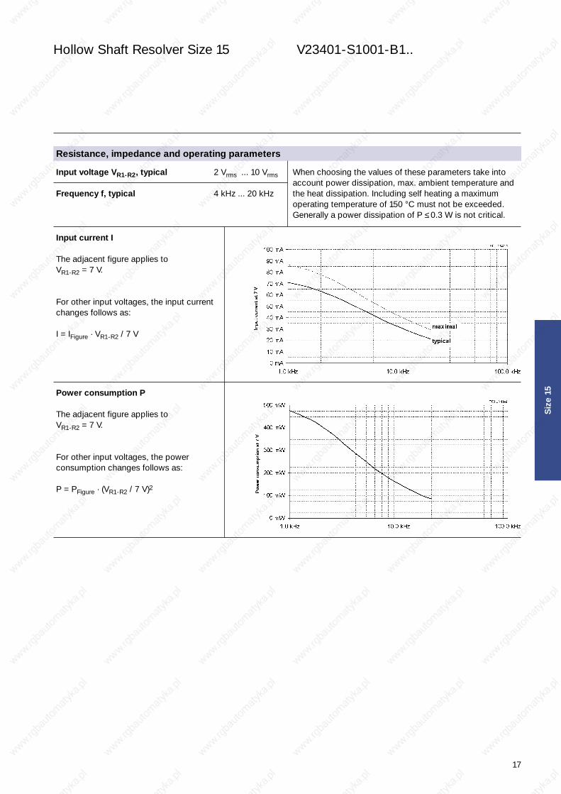
When choosing the values of these parameters take intoaccount power dissipation, max. ambient temperature andthe heat dissipation. Including self heating a maximum operating temperature of 150 °C must not be exceeded. Generally a power dissipation of P ≤ 0.3 W is not critical.
Input voltage VR1-R2, typical 2 Vrms ... 10 Vrms
Frequency f, typical 4 kHz ... 20 kHz
Input current I
The adjacent figure applies to VR1-R2 = 7 V.
For other input voltages, the input current changes follows as:
I = IFigure · VR1-R2 / 7 V
Power consumption P
The adjacent figure applies to VR1-R2 = 7 V.
For other input voltages, the power consumption changes follows as:
P = PFigure · (VR1-R2 / 7 V)2
Resistance, impedance and operating parameters
Hohlwellen - Inhalt 04.04.2001 17:01 Uhr Seite 17

18
Hollow Shaft Resolver Size 15 V23401-S1001-B1..
Siz
e 15
Resistance, impedance and operating parameters (continued)
DC resistance
The ohmic resistance values are based on an RR1-R2 = 82 Ωambient temperature of 22 °C and change with RS1-S3 = RS2-S4 = 68 Ωtemperature by 0.39 % / K Tolerance: ± 10 %
Input impedance
Tolerance: ± 15 % Tolerance: ± 15 %ZRO ... Impedance between R1 and R2 with open outputs ZRS ... Impedance between R1 and R2 with short circuits
between S1 and S3 as well as between S2 and S4
Output impedance
Tolerance: ± 15 % Tolerance: ± 15 %ZSO ... Impedance between S2 and S4 in a position of 0° ZSS ... Impedance between S1 and S3 in a position of 0°
(minimal coupling) with open outputs (max. coupling) with short circuits between R1 and R2
Inductance L
L = X / (2 · π · f) LRO = 2.5 mHat f = 5 kHz LSS = 5.8 mH
Hohlwellen - Inhalt 04.04.2001 17:01 Uhr Seite 18

19
Hollow Shaft Resolver Size 21 V23401-T1…/T2…V23401-H1…/H2…V23401-U1…/U2…
High-voltage test Windings to housing 500 VAC, 50 Hz Windings to each other 250 VAC, 50 Hz
Insulation resistance Windings to housing and Rinsulation > 50 MΩ at 500 VDCwindings to each other
Operating temperature range –55 °C ... +150 °C
Weight V23401-T10... approx. 240 g V23401-H10... approx. 290 g V23401-U10… approx. 290 g V23401-T20… approx. 210 g V23401-H20… approx. 260 g V23401-U20… approx. 260 g
Momentum of inertia of the rotor approx. 200 g · cm2
Maximum rational speed 20000 rpm
Maximum angular acceleration 64000 rad/s2
Torsional strength of rotor components 1 Nm
Shock resistance (11 ms sine) 1000 m/s2
Vibration fatigue limit (0 ... 2 kHz) 200 m/s2
Permissible radial runout 0.075 mm (see Dimensioned drawing: Note 1)
Permissible axial offset ± 0.5 mm(see Dimensioned drawing: Note 2)
Transfer function
Electrical and thermal limits
Mechanical data
Function
VS1-S3 = +rT · VR1-R2 · cos(p · α) VS2-S4 = +rT · VR1-R2 · sin(p · α)
p = pairs of poles
This function applies to the clockwise rotationof the rotor when looking at the (grooveless)transformer component from the top.
Siz
e 21
(yellow / white)
(red / white)
(yellow)
(blue)
(red)
(black)
Hohlwellen - Inhalt 04.04.2001 17:01 Uhr Seite 19

20
Hollow Shaft Resolver Size 21 V23401-T1… V23401-H1… V23401-U1…
Dimensioned drawing
V23401-T1... / H1... / U1...
Siz
e 21
AWG 26, Teflon-coatedL = 300 mm
1) Total runout when installed
2) Axial offset
Hohlwellen - Inhalt 04.04.2001 17:01 Uhr Seite 20

21
Hollow Shaft Resolver Size 21 V23401-T2… V23401-H2… V23401-U2…
Dimensioned drawing
V23401-T2... / H2... / U2...
Siz
e 21
AWG 26, Teflon-coatedL = 300 mm
1) Total runout when installed
2) Axial offset
Hohlwellen - Inhalt 04.04.2001 17:01 Uhr Seite 21

22
Hollow Shaft Resolver Size 21 V23401-T1002-B1.. V23401-H1002-B1.. 3-Speed
Housing Aluminum V23401-T1002-B1.. CrNi-steel V23401-H1002-B1..
Siz
e 21
Angular error spread ∆ϕ Ordering code Aluminum housing CrNi-steel housing
± 20′ V23401-T1002-B114 V23401-H1002-B114± 15′ V23401-T1002-B122 V23401-H1002-B122± 10′ V23401-T1002-B101 V23401-H1002-B101± 7′ V23401-T1002-B102 V23401-H1002-B102
Residual voltage Vresidual 25 mV at VR1-R2 = 7 V
Electrical data at 22 °C.
Transfer function
Pairs of poles p p = 3
Transformation ratio rT
rT = VS1-S3 max / VR1-R2
rT = VS2-S4 max / VR1-R2
ü = 0.5 ± 10 % within 3 ... 20 kHz = 0.5 ± 5 % at 5 kHz
Phase shift ψ
VR1-R2(t) = VR1-R2 max · sin(2 · π · f · t)
VS1-S3(t) = VS1-S3 max · sin(2 · π · f · t - ψ)
for –90° < α < +90°
Tolerance: ± 5°
Electrical error / Ordering information
Hohlwellen - Inhalt 04.04.2001 17:01 Uhr Seite 22

23
Hollow Shaft Resolver Size 21 V23401-T 1002-B1.. V23401-H1002-B1.. 3-Speed
Siz
e 21
When choosing the values of these parameters take intoaccount power dissipation, max. ambient temperature andthe heat dissipation. Including self heating a maximum operating temperature of 150 °C must not be exceeded. Generally a power dissipation of P ≤ 0.5 W is not critical.
Input voltage VR1-R2, typical 4 Vrms ... 10 Vrms
Frequency f, typical 3 kHz ... 15 kHz
Input current I
The adjacent figure applies to VR1-R2 = 7 V.
For other input voltages, the input current changes follows as:
I = IFigure · VR1-R2 / 7 V
Power consumption P
The adjacent figure applies to VR1-R2 = 7 V.
For other input voltages, the power consumption changes follows as:
P = PFigure · (VR1-R2 / 7 V)2
Resistance, impedance and operating parameters
Hohlwellen - Inhalt 04.04.2001 17:01 Uhr Seite 23

24
Hollow Shaft Resolver Size 21 V23401-T1002-B1.. V23401-H1002-B1.. 3-Speed
Siz
e 21
Resistance, impedance and operating parameters (continued)
DC resistance
The ohmic resistance values are based on an RR1-R2 = 39 Ωambient temperature of 22 °C and change with RS1-S3 = RS2-S4 = 94 Ωtemperature by 0.39 % / K Tolerance: ± 10 %
Input impedance
Tolerance: ± 15 % Tolerance: ± 15 %ZRO ... Impedance between R1 and R2 with open outputs ZRS ... Impedance between R1 and R2 with short circuits
between S1 and S3 as well as between S2 and S4
Output impedance
Tolerance: ± 15 % Tolerance: ± 15 %ZSO ... Impedance between S2 and S4 in a position of 0° ZSS ... Impedance between S1 and S3 in a position of 0°
(minimal coupling) with open outputs (max. coupling) with short circuits between R1 and R2
Inductance L
L = X / (2 · π · f) LRO = 4.7 mHat f = 8 kHz LSS = 8.8 mH
Hohlwellen - Inhalt 04.04.2001 17:01 Uhr Seite 24

25
Hollow Shaft Resolver Size 21 V23401-T 1005-B1.. V23401-H1005-B1..
Siz
e 21
Housing Aluminum V23401-T1005-B1.. CrNi-steel V23401-H1005-B1..
Angular error spread ∆ϕ Ordering code Aluminum housing CrNi-steel housing
± 20′ V23401-T1005-B114 V23401-H1005-B114± 15′ V23401-T1005-B122 V23401-H1005-B122± 10′ V23401-T1005-B101 V23401-H1005-B101± 7′ V23401-T1005-B102 V23401-H1005-B102
Residual voltage Vresidual 25 mV at VR1-R2 = 7 V
Electrical data at 22 °C.
Transfer function
Pairs of poles p p = 1
Transformation ratio rT
rT = VS1-S3 max / VR1-R2
rT = VS2-S4 max / VR1-R2
ü = 0.5 ± 10 % within 2 ... 10 kHz = 0.5 ± 5 % at 5 kHz
Phase shift ψ
VR1-R2(t) = VR1-R2 max · sin(2 · π · f · t)
VS1-S3(t) = VS1-S3 max · sin(2 · π · f · t - ψ)
for –90° < α < +90°
Tolerance: ± 5°
Electrical error / Ordering information
Hohlwellen - Inhalt 04.04.2001 17:01 Uhr Seite 25

26
Hollow Shaft Resolver Size 21 V23401-T1005-B1.. V23401-H1005-B1..
Siz
e 21
When choosing the values of these parameters take intoaccount power dissipation, max. ambient temperature andthe heat dissipation. Including self heating a maximum operating temperature of 150 °C must not be exceeded. Generally a power dissipation of P ≤ 0.5 W is not critical.
Input voltage VR1-R2, typical 4 Vrms ... 12 Vrms
Frequency f, typical 2 kHz ... 10 kHz
Input current I
The adjacent figure applies to VR1-R2 = 7 V.
For other input voltages, the input current changes follows as:
I = IFigure · VR1-R2 / 7 V
Power consumption P
The adjacent figure applies to VR1-R2 = 7 V.
For other input voltages, the power consumption changes follows as:
P = PFigure · (VR1-R2 / 7 V)2
Resistance, impedance and operating parameters
Hohlwellen - Inhalt 04.04.2001 17:01 Uhr Seite 26

27
Hollow Shaft Resolver Size 21 V23401-T 1005-B1.. V23401-H1005-B1..
Siz
e 21
Resistance, impedance and operating parameters (continued)
DC resistance
The ohmic resistance values are based on an RR1-R2 = 24 Ωambient temperature of 22 °C and change with RS1-S3 = RS2-S4 = 58 Ωtemperature by 0.39 % / K Tolerance: ± 10 %
Input impedance
Tolerance: ± 15 % Tolerance: ± 15 %ZRO ... Impedance between R1 and R2 with open outputs ZRS ... Impedance between R1 and R2 with short circuits
between S1 and S3 as well as between S2 and S4
Output impedance
Tolerance: ± 15 % Tolerance: ± 15 %ZSO ... Impedance between S2 and S4 in a position of 0° ZSS ... Impedance between S1 and S3 in a position of 0°
(minimal coupling) with open outputs (max. coupling) with short circuits between R1 and R2
Inductance L
L = X / (2 · π · f) LRO = 7.9 mHat f = 10 kHz LSS = 6.9 mH
Hohlwellen - Inhalt 04.04.2001 17:01 Uhr Seite 27

28
Hollow Shaft Resolver Size 21 V23401-T1009-B1.. V23401-H1009-B1.. with low output impedance
Siz
e 21
Housing Aluminum V23401-T1009-B1.. CrNi-steel V23401-H1009-B1..
Angular error spread ∆ϕ Ordering code Aluminum housing CrNi-steel housing
± 20′ V23401-T1009-B114 V23401-H1009-B114± 15′ V23401-T1009-B122 V23401-H1009-B122± 10′ V23401-T1009-B101 V23401-H1009-B101± 7′ V23401-T1009-B102 V23401-H1009-B102
Residual voltage Vresidual 14 mV at VR1-R2 = 4 V
Electrical data at 22 °C.
Transfer function
Pairs of poles p p = 1
Transformation ratio rT
rT = VS1-S3 max / VR1-R2
rT = VS2-S4 max / VR1-R2
ü = 0.5 ± 10 % within 2 ... 8 kHz = 0.5 ± 5 % at 5 kHz
Phase shift ψ
VR1-R2(t) = VR1-R2 max · sin(2 · π · f · t)
VS1-S3(t) = VS1-S3 max · sin(2 · π · f · t - ψ)
for –90° < α < +90°
Tolerance: ± 5°
Electrical error / Ordering information
Hohlwellen - Inhalt 04.04.2001 17:01 Uhr Seite 28

29
Hollow Shaft Resolver Size 21 V23401-T 1009-B1.. V23401-H1009-B1.. with low output impedance
Siz
e 21
When choosing the values of these parameters take intoaccount power dissipation, max. ambient temperature andthe heat dissipation. Including self heating a maximum operating temperature of 150 °C must not be exceeded. Generally a power dissipation of P ≤ 0.5 W is not critical.
Input voltage VR1-R2, typical 2 Vrms ... 8 Vrms
Frequency f, typical 2 kHz ... 10 kHz
Input current I
The adjacent figure applies to VR1-R2 = 4 V.
For other input voltages, the input current changes follows as:
I = IFigure · VR1-R2 / 4 V
Power consumption P
The adjacent figure applies to VR1-R2 = 4 V.
For other input voltages, the power consumption changes follows as:
P = PFigure · (VR1-R2 / 4 V)2
Resistance, impedance and operating parameters
Hohlwellen - Inhalt 04.04.2001 17:01 Uhr Seite 29

30
Hollow Shaft Resolver Size 21 V23401-T1009-B1.. V23401-H1009-B1.. with low output impedance
Siz
e 21
Resistance, impedance and operating parameters (continued)
DC resistance
The ohmic resistance values are based on an RR1-R2 = 21 Ωambient temperature of 22 °C and change with RS1-S3 = RS2-S4 = 22 Ωtemperature by 0.39 % / K Tolerance: ± 10 %
Input impedance
Tolerance: ± 15 % Tolerance: ± 15 %ZRO ... Impedance between R1 and R2 with open outputs ZRS ... Impedance between R1 and R2 with short circuits
between S1 and S3 as well as between S2 and S4
Output impedance
Tolerance: ± 15 % Tolerance: ± 15 %ZSO ... Impedance between S2 and S4 in a position of 0° ZSS ... Impedance between S1 and S3 in a position of 0°
(minimal coupling) with open outputs (max. coupling) with short circuits between R1 and R2
Inductance L
L = X / (2 · π · f) LRO = 3.5 mHat f = 10 kHz LSS = 3.1 mH
Hohlwellen - Inhalt 04.04.2001 17:01 Uhr Seite 30
31
Hollow Shaft Resolver Size 21 V23401-T 2001-B2.. V23401-H2001-B2..
Siz
e 21
Housing Aluminum V23401-T2001-B2.. CrNi-steel V23401-H2001-B2..
Angular error spread ∆ϕ Ordering code Aluminum housing CrNi-steel housing
± 20′ V23401-T2001-B214 V23401-H2001-B214± 15′ V23401-T2001-B222 V23401-H2001-B222± 10′ V23401-T2001-B201 V23401-H2001-B201± 7′ V23401-T2001-B202 V23401-H2001-B202
Residual voltage Vresidual 25 mV at VR1-R2 = 7 V
Electrical data at 22 °C.
Transfer function
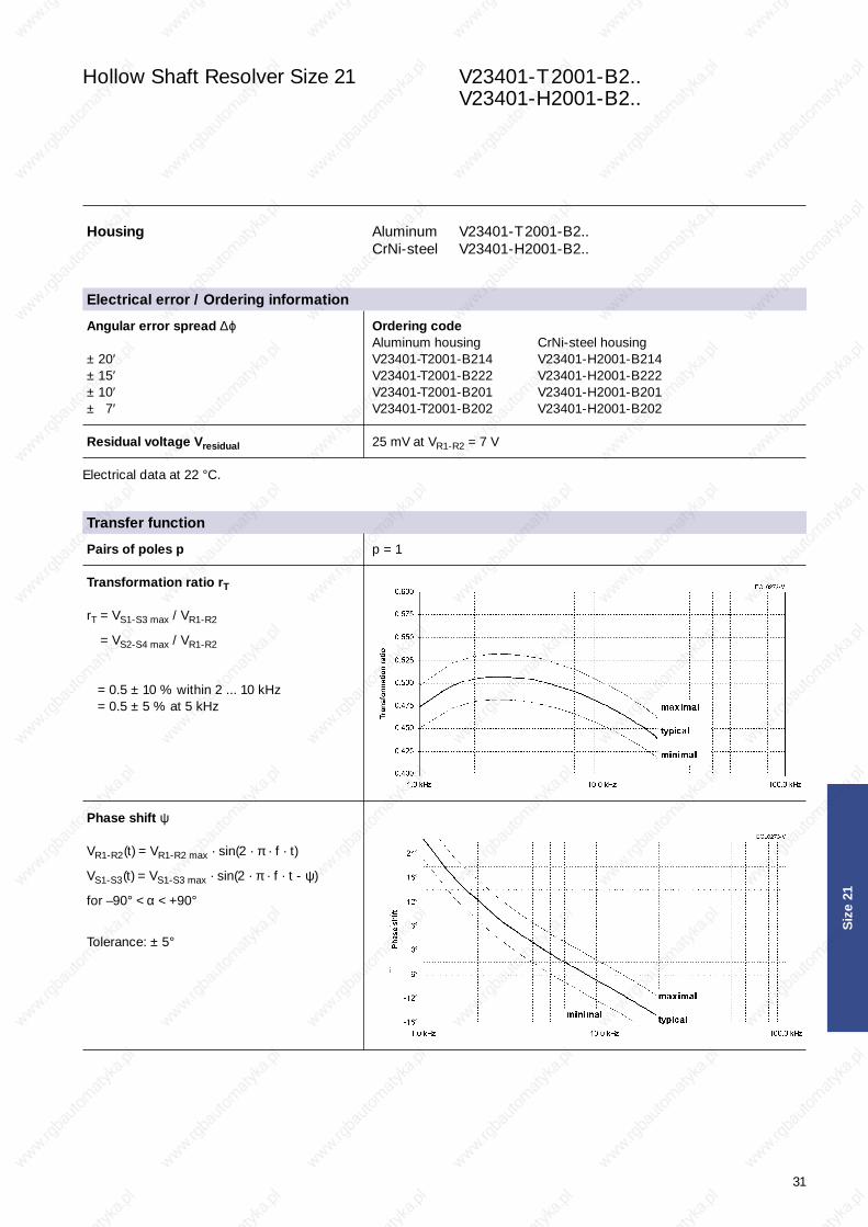
Pairs of poles p p = 1
Transformation ratio rT
rT = VS1-S3 max / VR1-R2
rT = VS2-S4 max / VR1-R2
ü = 0.5 ± 10 % within 2 ... 10 kHz = 0.5 ± 5 % at 5 kHz
Phase shift ψ
VR1-R2(t) = VR1-R2 max · sin(2 · π · f · t)
VS1-S3(t) = VS1-S3 max · sin(2 · π · f · t - ψ)
for –90° < α < +90°
Tolerance: ± 5°
Electrical error / Ordering information
Hohlwellen - Inhalt 04.04.2001 17:01 Uhr Seite 31

32
Hollow Shaft Resolver Size 21 V23401-T2001-B2.. V23401-H2001-B2..
Siz
e 21
When choosing the values of these parameters take intoaccount power dissipation, max. ambient temperature andthe heat dissipation. Including self heating a maximum operating temperature of 150 °C must not be exceeded. Generally a power dissipation of P ≤ 0.5 W is not critical.
Input voltage VR1-R2, typical 4 Vrms ... 12 Vrms
Frequency f, typical 2 kHz ... 10 kHz
Input current I
The adjacent figure applies to VR1-R2 = 7 V.
For other input voltages, the input current changes follows as:
I = IFigure · VR1-R2 / 7 V
Power consumption P
The adjacent figure applies to VR1-R2 = 7 V.
For other input voltages, the power consumption changes follows as:
P = PFigure · (VR1-R2 / 7 V)2
Resistance, impedance and operating parameters
Hohlwellen - Inhalt 04.04.2001 17:01 Uhr Seite 32

33
Hollow Shaft Resolver Size 21 V23401-T 2001-B2.. V23401-H2001-B2..
Siz
e 21
Resistance, impedance and operating parameters (continued)
DC resistance
The ohmic resistance values are based on an RR1-R2 = 24 Ωambient temperature of 22 °C and change with RS1-S3 = RS2-S4 = 58 Ωtemperature by 0.39 % / K Tolerance: ± 10 %
Input impedance
Tolerance: ± 15 % Tolerance: ± 15 %ZRO ... Impedance between R1 and R2 with open outputs ZRS ... Impedance between R1 and R2 with short circuits
between S1 and S3 as well as between S2 and S4
Output impedance
Tolerance: ± 15 % Tolerance: ± 15 %ZSO ... Impedance between S2 and S4 in a position of 0° ZSS ... Impedance between S1 and S3 in a position of 0°
(minimal coupling) with open outputs (max. coupling) with short circuits between R1 and R2
Inductance L
L = X / (2 · π · f) LRO = 7.9 mHat f = 10 kHz LSS = 6.9 mH
Hohlwellen - Inhalt 04.04.2001 17:01 Uhr Seite 33

34
Hollow Shaft Resolver Size 21 V23401-T2009-B2.. V23401-H2009-B2.. with low output impedance
Siz
e 21
Housing Aluminum V23401-T2009-B2.. CrNi-steel V23401-H2009-B2..
Angular error spread ∆ϕ Ordering code Aluminum housing CrNi-steel housing
± 20′ V23401-T2009-B214 V23401-H2009-B214± 15′ V23401-T2009-B222 V23401-H2009-B222± 10′ V23401-T2009-B201 V23401-H2009-B201± 7′ V23401-T2009-B202 V23401-H2009-B202
Residual voltage Vresidual 14 mV at VR1-R2 = 4 V
Electrical data at 22 °C.
Transfer function
Pairs of poles p p = 1
Transformation ratio rT
rT = VS1-S3 max / VR1-R2
rT = VS2-S4 max / VR1-R2
ü = 0.5 ± 10 % within 2 ... 8 kHz = 0.5 ± 5 % at 5 kHz
Phase shift ψ
VR1-R2(t) = VR1-R2 max · sin(2 · π · f · t)
VS1-S3(t) = VS1-S3 max · sin(2 · π · f · t - ψ)
for –90° < α < +90°
Tolerance: ± 5°
Electrical error / Ordering information
Hohlwellen - Inhalt 04.04.2001 17:01 Uhr Seite 34

35
Hollow Shaft Resolver Size 21 V23401-T 2009-B2.. V23401-H2009-B2.. with low output impedance
Siz
e 21
When choosing the values of these parameters take intoaccount power dissipation, max. ambient temperature andthe heat dissipation. Including self heating a maximum operating temperature of 150 °C must not be exceeded. Generally a power dissipation of P ≤ 0.5 W is not critical.
Input voltage VR1-R2, typical 2 Vrms ... 8 Vrms
Frequency f, typical 2 kHz ... 10 kHz
Input current I
The adjacent figure applies to VR1-R2 = 4 V.
For other input voltages, the input current changes follows as:
I = IFigure · VR1-R2 / 4 V
Power consumption P
The adjacent figure applies to VR1-R2 = 4 V.
For other input voltages, the power consumption changes follows as:
P = PFigure · (VR1-R2 / 4 V)2
Resistance, impedance and operating parameters
Hohlwellen - Inhalt 04.04.2001 17:01 Uhr Seite 35

36
Hollow Shaft Resolver Size 21 V23401-T2009-B2.. V23401-H2009-B2.. with low output impedance
Siz
e 21
Resistance, impedance and operating parameters (continued)
DC resistance
The ohmic resistance values are based on an RR1-R2 = 21 Ωambient temperature of 22 °C and change with RS1-S3 = RS2-S4 = 22 Ωtemperature by 0.39 % / K Tolerance: ± 10 %
Input impedance
Tolerance: ± 15 % Tolerance: ± 15 %ZRO ... Impedance between R1 and R2 with open outputs ZRS ... Impedance between R1 and R2 with short circuits
between S1 and S3 as well as between S2 and S4
Output impedance
Tolerance: ± 15 % Tolerance: ± 15 %ZSO ... Impedance between S2 and S4 in a position of 0° ZSS ... Impedance between S1 and S3 in a position of 0°
(minimal coupling) with open outputs (max. coupling) with short circuits between R1 and R2
Inductance L
L = X / (2 · π · f) LRO = 3.5 mHat f = 10 kHz LSS = 3.1 mH
Hohlwellen - Inhalt 04.04.2001 17:01 Uhr Seite 36

37
Hollow Shaft Resolver Size 21 V23401-T 2010-B2.. V23401-H2010-B2.. 3-speed
Siz
e 21
Housing Aluminum V23401-T2010-B2.. CrNi-steel V23401-H2010-B2..
Angular error spread ∆ϕ Ordering code Aluminum housing CrNi-steel housing
± 20′ V23401-T2010-B214 V23401-H2010-B214± 15′ V23401-T2010-B222 V23401-H2010-B222± 10′ V23401-T2010-B201 V23401-H2010-B201± 7′ V23401-T2010-B202 V23401-H2010-B202
Residual voltage Vresidual 20 mV at VR1-R2 = 6 V
Electrical data at 22 °C.
Transfer function
Pairs of poles p p = 3
Transformation ratio rT
rT = VS1-S3 max / VR1-R2
rT = VS2-S4 max / VR1-R2
ü = 0.46 ± 10 % within 3 ... 20 kHz = 0.46 ± 5 % at 6 kHz
Phase shift ψ
VR1-R2(t) = VR1-R2 max · sin(2 · π · f · t)
VS1-S3(t) = VS1-S3 max · sin(2 · π · f · t - ψ)
for –90° < α < +90°
Tolerance: ± 5°
Electrical error / Ordering information
Hohlwellen - Inhalt 04.04.2001 17:01 Uhr Seite 37
38
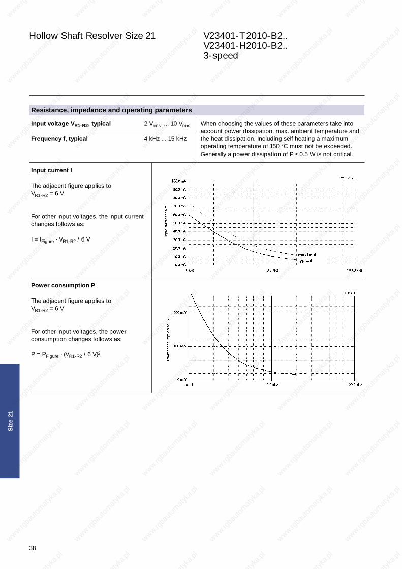
Hollow Shaft Resolver Size 21 V23401-T2010-B2.. V23401-H2010-B2.. 3-speed
Siz
e 21
When choosing the values of these parameters take intoaccount power dissipation, max. ambient temperature andthe heat dissipation. Including self heating a maximum operating temperature of 150 °C must not be exceeded. Generally a power dissipation of P ≤ 0.5 W is not critical.
Input voltage VR1-R2, typical 2 Vrms ... 10 Vrms
Frequency f, typical 4 kHz ... 15 kHz
Input current I
The adjacent figure applies to VR1-R2 = 6 V.
For other input voltages, the input current changes follows as:
I = IFigure · VR1-R2 / 6 V
Power consumption P
The adjacent figure applies to VR1-R2 = 6 V.
For other input voltages, the power consumption changes follows as:
P = PFigure · (VR1-R2 / 6 V)2
Resistance, impedance and operating parameters
Hohlwellen - Inhalt 04.04.2001 17:01 Uhr Seite 38

39
Hollow Shaft Resolver Size 21 V23401-T 2010-B2.. V23401-H2010-B2.. 3-speed
Siz
e 21
Resistance, impedance and operating parameters (continued)
DC resistance
The ohmic resistance values are based on an RR1-R2 = 55 Ωambient temperature of 22 °C and change with RS1-S3 = RS2-S4 = 173 Ωtemperature by 0.39 % / K Tolerance: ± 10 %
Input impedance
Tolerance: ± 15 % Tolerance: ± 15 %ZRO ... Impedance between R1 and R2 with open outputs ZRS ... Impedance between R1 and R2 with short circuits
between S1 and S3 as well as between S2 and S4
Output impedance
Tolerance: ± 15 % Tolerance: ± 15 %ZSO ... Impedance between S2 and S4 in a position of 0° ZSS ... Impedance between S1 and S3 in a position of 0°
(minimal coupling) with open outputs (max. coupling) with short circuits between R1 and R2
Inductance L
L = X / (2 · π · f) LRO = 8.1 mHat f = 10 kHz LSS = 11.4 mH
Hohlwellen - Inhalt 04.04.2001 17:01 Uhr Seite 39

40
Hollow Shaft Resolver Size 21 V23401-T2014-B2.. V23401-H2014-B2.. 4-speed
Siz
e 21
Housing Aluminum V23401-T2014-B2.. CrNi-steel V23401-H2014-B2..
Angular error spread ∆ϕ Ordering code Aluminum housing CrNi-steel housing
± 20′ V23401-T2014-B214 V23401-H2014-B214± 15′ V23401-T2014-B222 V23401-H2014-B222± 10′ V23401-T2014-B201 V23401-H2014-B201± 7′ V23401-T2014-B202 V23401-H2014-B202
Residual voltage Vresidual 20 mV at VR1-R2 = 6 V
Electrical data at 22 °C.
Transfer function
Pairs of poles p p = 4
Transformation ratio rT
rT = VS1-S3 max / VR1-R2
rT = VS2-S4 max / VR1-R2
ü = 0.46 ± 10 % within 4 ... 15 kHz = 0.46 ± 5 % at 6 kHz
Phase shift ψ
VR1-R2(t) = VR1-R2 max · sin(2 · π · f · t)
VS1-S3(t) = VS1-S3 max · sin(2 · π · f · t - ψ)
for –90° < α < +90°
Tolerance: ± 5°
Electrical error / Ordering information
Hohlwellen - Inhalt 04.04.2001 17:01 Uhr Seite 40

41
Hollow Shaft Resolver Size 21 V23401-T 2014-B2.. V23401-H2014-B2.. 4-speed
Siz
e 21
When choosing the values of these parameters take intoaccount power dissipation, max. ambient temperature andthe heat dissipation. Including self heating a maximum operating temperature of 150 °C must not be exceeded. Generally a power dissipation of P ≤ 0.5 W is not critical.
Input voltage VR1-R2, typical 2 Vrms ... 10 Vrms
Frequency f, typical 4 kHz ... 15 kHz
Input current I
The adjacent figure applies to VR1-R2 = 6 V.
For other input voltages, the input current changes follows as:
I = IFigure · VR1-R2 / 6 V
Power consumption P
The adjacent figure applies to VR1-R2 = 6 V.
For other input voltages, the power consumption changes follows as:
P = PFigure · (VR1-R2 / 6 V)2
Resistance, impedance and operating parameters
Hohlwellen - Inhalt 04.04.2001 17:01 Uhr Seite 41

42
Hollow Shaft Resolver Size 21 V23401-T2014-B2.. V23401-H2014-B2.. 4-speed
Siz
e 21
Resistance, impedance and operating parameters (continued)
DC resistance
The ohmic resistance values are based on an RR1-R2 = 36 Ωambient temperature of 22 °C and change with RS1-S3 = RS2-S4 = 48 Ωtemperature by 0.39 % / K Tolerance: ± 10 %
Input impedance
Tolerance: ± 15 % Tolerance: ± 15 %ZRO ... Impedance between R1 and R2 with open outputs ZRS ... Impedance between R1 and R2 with short circuits
between S1 and S3 as well as between S2 and S4
Output impedance
Tolerance: ± 15 % Tolerance: ± 15 %ZSO ... Impedance between S2 and S4 in a position of 0° ZSS ... Impedance between S1 and S3 in a position of 0°
(minimal coupling) with open outputs (max. coupling) with short circuits between R1 and R2
Inductance L
L = X / (2 · π · f) LRO = 3.4 mHat f = 10 kHz LSS = 7.8 mH
Hohlwellen - Inhalt 04.04.2001 17:01 Uhr Seite 42

43
Hollow Shaft Resolver Size 21 V23401-T 2015-B2.. V23401-H2015-B2.. 2-speed
Siz
e 21
Housing Aluminum V23401-T2015-B2.. CrNi-steel V23401-H2015-B2..
Angular error spread ∆ϕ Ordering code Aluminum housing CrNi-steel housing
± 20′ V23401-T2015-B214 V23401-H2015-B214± 15′ V23401-T2015-B222 V23401-H2015-B222± 10′ V23401-T2015-B201 V23401-H2015-B201± 7′ V23401-T2015-B202 V23401-H2015-B202
Residual voltage Vresidual 21 mV at VR1-R2 = 6 V
Electrical data at 22 °C.
Transfer function
Pairs of poles p p = 2
Transformation ratio rT
rT = VS1-S3 max / VR1-R2
rT = VS2-S4 max / VR1-R2
ü = 0.5 ± 10 % within 4 ... 20 kHz = 0.5 ± 5 % at 10 kHz
Phase shift ψ
VR1-R2(t) = VR1-R2 max · sin(2 · π · f · t)
VS1-S3(t) = VS1-S3 max · sin(2 · π · f · t - ψ)
for –90° < α < +90°
Tolerance: ± 5°
Electrical error / Ordering information
Hohlwellen - Inhalt 04.04.2001 17:01 Uhr Seite 43

44
Hollow Shaft Resolver Size 21 V23401-T2015-B2.. V23401-H2015-B2.. 2-speed
Siz
e 21
When choosing the values of these parameters take intoaccount power dissipation, max. ambient temperature andthe heat dissipation. Including self heating a maximum operating temperature of 150 °C must not be exceeded. Generally a power dissipation of P ≤ 0.5 W is not critical.
Input voltage VR1-R2, typical 2 Vrms ... 10 Vrms
Frequency f, typical 4 kHz ... 15 kHz
Input current I
The adjacent figure applies to VR1-R2 = 6 V.
For other input voltages, the input current changes follows as:
I = IFigure · VR1-R2 / 6 V
Power consumption P
The adjacent figure applies to VR1-R2 = 6 V.
For other input voltages, the power consumption changes follows as:
P = PFigure · (VR1-R2 / 6 V)2
Resistance, impedance and operating parameters
Hohlwellen - Inhalt 04.04.2001 17:01 Uhr Seite 44

45
Hollow Shaft Resolver Size 21 V23401-T 2015-B2.. V23401-H2015-B2.. 2-speed
Siz
e 21
Resistance, impedance and operating parameters (continued)
DC resistance
The ohmic resistance values are based on an RR1-R2 = 33 Ωambient temperature of 22 °C and change with RS1-S3 = RS2-S4 = 30 Ωtemperature by 0.39 % / K Tolerance: ± 10 %
Input impedance
Tolerance: ± 15 % Tolerance: ± 15 %ZRO ... Impedance between R1 and R2 with open outputs ZRS ... Impedance between R1 and R2 with short circuits
between S1 and S3 as well as between S2 and S4
Output impedance
Tolerance: ± 15 % Tolerance: ± 15 %ZSO ... Impedance between S2 and S4 in a position of 0° ZSS ... Impedance between S1 and S3 in a position of 0°
(minimal coupling) with open outputs (max. coupling) with short circuits between R1 and R2
Inductance L
L = X / (2 · π · f) LRO = 3.6 mHat f = 10 kHz LSS = 3.0 mH
Hohlwellen - Inhalt 04.04.2001 17:01 Uhr Seite 45

46
Hollow Shaft Resolver Size 21 V23401-U1016-B1..
Siz
e 21
Housing CrMo-steel
Angular error spread ∆ϕ Ordering code ± 10′ V23401-U1016-B101 ± 8′ V23401-U1016-B109 ± 6′ V23401-U1016-B110 ± 4′ V23401-U1016-B133
Residual voltage Vresidual 14 mV at VR1-R2 = 4 V
Electrical data at 22 °C.
Transfer function
Pairs of poles p p = 1
Transformation ratio rT
rT = VS1-S3 max / VR1-R2
rT = VS2-S4 max / VR1-R2
ü = 0.5 ± 20 % within 1.5 ... 10 kHz = 0.5 ± 10 % at 5 kHz
Phase shift ψ
VR1-R2(t) = VR1-R2 max · sin(2 · π · f · t)
VS1-S3(t) = VS1-S3 max · sin(2 · π · f · t - ψ)
for –90° < α < +90°
Tolerance: ± 5°
Electrical error / Ordering information
Hohlwellen - Inhalt 04.04.2001 17:01 Uhr Seite 46

47
Hollow Shaft Resolver Size 21 V23401-U1016-B1..
Siz
e 21
When choosing the values of these parameters take intoaccount power dissipation, max. ambient temperature andthe heat dissipation. Including self heating a maximum operating temperature of 150 °C must not be exceeded. Generally a power dissipation of P ≤ 0.5 W is not critical.
Input voltage VR1-R2, typical 2 Vrms ... 20 Vrms
Frequency f, typical 2 kHz ... 10 kHz
Input current I
The adjacent figure applies to VR1-R2 = 4 V.
For other input voltages, the input current changes follows as:
I = IFigure · VR1-R2 / 4 V
Power consumption P
The adjacent figure applies to VR1-R2 = 4 V.
For other input voltages, the power consumption changes follows as:
P = PFigure · (VR1-R2 / 4 V)2
Resistance, impedance and operating parameters
Hohlwellen - Inhalt 04.04.2001 17:01 Uhr Seite 47

48
Hollow Shaft Resolver Size 21 V23401-U1016-B1..
Siz
e 21
Resistance, impedance and operating parameters (continued)
DC resistance
The ohmic resistance values are based on an RR1-R2 = 65 Ωambient temperature of 22 °C and change with RS1-S3 = RS2-S4 = 81 Ωtemperature by 0.39 % / K Tolerance: ± 15 %
Input impedance
Tolerance: ± 20 % Tolerance: ± 20 %ZRO ... Impedance between R1 and R2 with open outputs ZRS ... Impedance between R1 and R2 with short circuits
between S1 and S3 as well as between S2 and S4
Output impedance
Tolerance: ± 20 % Tolerance: ± 20 %ZSO ... Impedance between S2 and S4 in a position of 0° ZSS ... Impedance between S1 and S3 in a position of 0°
(minimal coupling) with open outputs (max. coupling) with short circuits between R1 and R2
Inductance L
L = X / (2 · π · f) LRO = 6 mHat f = 5 kHz LSS = 13 mH
Hohlwellen - Inhalt 04.04.2001 17:01 Uhr Seite 48

49
Hollow Shaft Resolver Size 21 V23401-U2017-B2..
Siz
e 21
Housing CrMo-steel
Angular error spread ∆ϕ Ordering code ± 10′ V23401-U2017-B201 ± 7′ V23401-U2017-B202 ± 4′ V23401-U2017-B233
Residual voltage Vresidual 18 mV at VR1-R2 = 5 V
Electrical data at 22 °C.
Transfer function
Pairs of poles p p = 1
Transformation ratio rT
rT = VS1-S3 max / VR1-R2
rT = VS2-S4 max / VR1-R2
ü = 0.5 ± 20 % within 1 ... 10 kHz = 0.5 ± 10 % at 4 kHz
Phase shift ψ
VR1-R2(t) = VR1-R2 max · sin(2 · π · f · t)
VS1-S3(t) = VS1-S3 max · sin(2 · π · f · t - ψ)
for –90° < α < +90°
Tolerance: ± 5°
Electrical error / Ordering information
Hohlwellen - Inhalt 04.04.2001 17:01 Uhr Seite 49
50
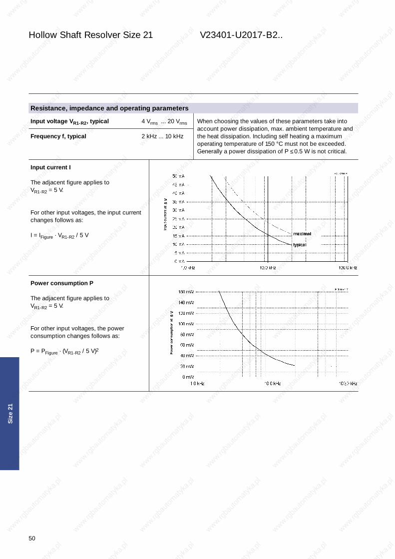
Hollow Shaft Resolver Size 21 V23401-U2017-B2..
Siz
e 21
When choosing the values of these parameters take intoaccount power dissipation, max. ambient temperature andthe heat dissipation. Including self heating a maximum operating temperature of 150 °C must not be exceeded. Generally a power dissipation of P ≤ 0.5 W is not critical.
Input voltage VR1-R2, typical 4 Vrms ... 20 Vrms
Frequency f, typical 2 kHz ... 10 kHz
Input current I
The adjacent figure applies to VR1-R2 = 5 V.
For other input voltages, the input current changes follows as:
I = IFigure · VR1-R2 / 5 V
Power consumption P
The adjacent figure applies to VR1-R2 = 5 V.
For other input voltages, the power consumption changes follows as:
P = PFigure · (VR1-R2 / 5 V)2
Resistance, impedance and operating parameters
Hohlwellen - Inhalt 04.04.2001 17:01 Uhr Seite 50

51
Hollow Shaft Resolver Size 21 V23401-U2017-B2..
Siz
e 21
Resistance, impedance and operating parameters (continued)
DC resistance
The ohmic resistance values are based on an RR1-R2 = 36 Ωambient temperature of 22 °C and change with RS1-S3 = RS2-S4 = 56 Ωtemperature by 0.39 % / K Tolerance: ± 15 %
Input impedance
Tolerance: ± 20 % Tolerance: ± 20 %ZRO ... Impedance between R1 and R2 with open outputs ZRS ... Impedance between R1 and R2 with short circuits
between S1 and S3 as well as between S2 and S4
Output impedance
Tolerance: ± 20 % Tolerance: ± 20 %ZSO ... Impedance between S2 and S4 in a position of 0° ZSS ... Impedance between S1 and S3 in a position of 0°
(minimal coupling) with open outputs (max. coupling) with short circuits between R1 and R2
Inductance L
L = X / (2 · π · f) LRO = 5.5 mHat f = 4 kHz LSS = 10.5 mH
Hohlwellen - Inhalt 04.04.2001 17:01 Uhr Seite 51

52
Hollow Shaft Resolver Size 21 V23401-U2020-B2.. 3-speed
Siz
e 21
Housing CrMo-steel
Angular error spread ∆ϕ Ordering code ± 10′ V23401-U2020-B201 ± 8′ V23401-U2020-B209 ± 6′ V23401-U2020-B210
Residual voltage Vresidual 20 mV at VR1-R2 = 6 V
Electrical data at 22 °C.
Transfer function
Pairs of poles p p = 3
Transformation ratio rT
rT = VS1-S3 max / VR1-R2
rT = VS2-S4 max / VR1-R2
ü = 0.5 ± 10 % within 3 ... 10 kHz = 0.5 ± 5 % at 6 kHz
Phase shift ψ
VR1-R2(t) = VR1-R2 max · sin(2 · π · f · t)
VS1-S3(t) = VS1-S3 max · sin(2 · π · f · t - ψ)
for –90° < α < +90°
Tolerance: ± 5°
Electrical error / Ordering information
Hohlwellen - Inhalt 04.04.2001 17:01 Uhr Seite 52

53
Hollow Shaft Resolver Size 21 V23401-U2020-B2.. 3-speed
Siz
e 21
When choosing the values of these parameters take intoaccount power dissipation, max. ambient temperature andthe heat dissipation. Including self heating a maximum operating temperature of 150 °C must not be exceeded. Generally a power dissipation of P ≤ 0.5 W is not critical.
Input voltage VR1-R2, typical 2 Vrms ... 10 Vrms
Frequency f, typical 4 kHz ... 10 kHz
Input current I
The adjacent figure applies to VR1-R2 = 6 V.
For other input voltages, the input current changes follows as:
I = IFigure · VR1-R2 / 6 V
Power consumption P
The adjacent figure applies to VR1-R2 = 6 V.
For other input voltages, the power consumption changes follows as:
P = PFigure · (VR1-R2 / 6 V)2
Resistance, impedance and operating parameters
Hohlwellen - Inhalt 04.04.2001 17:01 Uhr Seite 53

54
Hollow Shaft Resolver Size 21 V23401-U2020-B2.. 3-speed
Siz
e 21
Resistance, impedance and operating parameters (continued)
DC resistance
The ohmic resistance values are based on an RR1-R2 = 62 Ωambient temperature of 22 °C and change with RS1-S3 = RS2-S4 = 186 Ωtemperature by 0.39 % / K Tolerance: ± 10 %
Input impedance
Tolerance: ± 15 % Tolerance: ± 15 %ZRO ... Impedance between R1 and R2 with open outputs ZRS ... Impedance between R1 and R2 with short circuits
between S1 and S3 as well as between S2 and S4
Output impedance
Tolerance: ± 15 % Tolerance: ± 15 %ZSO ... Impedance between S2 and S4 in a position of 0° ZSS ... Impedance between S1 and S3 in a position of 0°
(minimal coupling) with open outputs (max. coupling) with short circuits between R1 and R2
Inductance L
L = X / (2 · π · f) LRO = 4 mHat f = 6 kHz LSS = 14 mH
Hohlwellen - Inhalt 04.04.2001 17:01 Uhr Seite 54

55
Engineering Notes
Siz
e 21
Hohlwellen - Inhalt 04.04.2001 17:01 Uhr Seite 55

56
Engineering Notes
Siz
e 21
Hohlwellen - Inhalt 04.04.2001 17:02 Uhr Seite 56

Worldwide Companies
AMP and TYCO are registered trademarks http://www.tycoelectronics.com
Americas
Europe/Middle East/Africa
Asia/Pacific
Argentina – Buenos Aires Phone: +54-1-733-2000 Fax: +54-1-717-0988
Brasil – São PauloPhone: +55-11-3611-1311Fax: +55-11-3611-0397
Canada – TorontoPhone: +905-475-6222Fax: +905-474-5520
Chile – Santiago Phone: +56-2-739-1230 Fax: +56-2-739-1227
Colombia – Bogota Phone: +57-1-231-9398 Fax: +57-1-240-3769
Mexico – Mexico CityPhone: +52-5-729-0400Fax: +52-5-361-8545
United States – Harrisburg, PA Phone: +717-564-0100 Fax: +717-986-7575
Venezuela – Caracas Phone: +58-2-986-7774 Fax: +58-2-986-9739
Austria – ViennaPhone: +43-1-90-560-0 Fax: +43-1-90-560-1333
Belgium – Kessel-LoPhone: +32-16-352-300 Fax: +32-16-352-352
Bulgaria – Sofia Phone: +359-2-971-2152 Fax: +359-2-971-2153
Croatia – Zagreb Phone: +385-1-67-04-46 Fax: +385-1-69-16-04
Czech Republic – KurimPhone: +420-5-41-162-111Fax: +420-5-41-162-223
Denmark – Viby Phone: +45-86-295-055 Fax: +45-86-295-133
England – Stanmore MiddlesexPhone: +44-181-954-2356Fax: +44-181-954-6234
Egypt – Cairo Phone: +20-2-417-76-47 Fax: +20-2-419-23-34
Estonia – HaabneemePhone: +372-6205-900 Fax: +372-6205-980
Finland – Helsinki Phone: +358-9-512-3420 Fax: +358-9-512-34250
France – Cergy-Pontoise CedexPhone: +33-1-3420-8888Fax: +33-1-3420-8600
France Export – St Ouen L’AumonePhone: +33-1-3440-7200Fax: +33-1-3440-7220 or
+33-1-3440-7230
France SIMEL – Gevrey-Chambertin Phone: +33-3-8058-3200Fax: +33-3-8034-1015
Germany – BensheimPhone: +49-6251-133-0Fax: +49-6251-133-1600
Germany HTS – NeunkirchenPhone: +49-2247-305-0Fax: +49-2247-305-122
Greece – Athens Phone: +30-1-9370-396/397Fax: +30-1-9370-655
Hungary – BudapestPhone: +36-1-289-1000 Fax: +36-1-289-1010
Ireland – Dublin Phone: +353-1-820-3000 Fax: +353-1-820-9790
Israel – Tel Aviv Phone: +972-3-649-1482 Fax: +972-3-648-4041
Italy – Collegno (Torino)Phone: +39-011-4012-111Fax: +39-011-403-11-16
Lithuania – Vilnius Phone: +370-2-231-402 Fax: +370-2-231-403
The Netherlands‘s-HertogenboschPhone: +31-73-6246-246Fax: +31-73-6246-935
Norway – Nesbru Phone: +47-66-77-8899 Fax: +47-66-77-8855
Poland – WarsawPhone: +48-22-54-90-888Fax: +48-22-54-90-880
Portugal – LisbonPhone: +351-21-384-58-90Fax: +351-21-387-71-72
Romania – Bucharest Phone: +40-1-311-3479 + 3596Fax: +40-1-312-0574
Russia – Moscow Phone: +7-095-926-55-06…09Fax: +7-095-926-55-05
Russia – St. Petersburg Phone: +7-812-325-30-83Fax: +7-812-325-32-88
Slovakia – Banská Bystrica Phone: +421-88-415-20-11/12Fax: +421-88-415-20-13
Slovenia – Ljubljana Phone: +386-61-161-3270Fax: +386-61-161-3240
South Africa – Midrand Phone: +27-11-314-10-89 Fax: +27-11-314-19-10
Spain – BarcelonaPhone: +34-93-291-0330Fax: +34-93-201-7879
Sweden – Upplands VäsbyPhone: +46-8-50-72-50-00 Fax: +46-8-50-72-50-01
Switzerland – Steinach Phone: +41-71-447-0447Fax: +41-71-447-0444
Turkey – Istanbul Phone: +90-212-281-8181…3Fax: +90-212-281-8184
Ukraine – Kiev Phone: +38-044-238-6908Fax: +38-044-238-6596
Australia – Sydney Phone: +61-2-9840-8200 Fax: +61-2-9899-5649
India – Bangalore Phone: +91-80-841-0200 Fax: +91-80-841-0210
Indonesia – Jakarta Phone: +6221-526-7852 Fax: +6221-526-7856
Japan – Kawasaki, KanagawaPhone: +81-44-844-8079Fax: +81-44-844-8733
Korea – Seoul Phone: +82-2-3274-0535 Fax: +82-2-3274-0524/0531
Malaysia – Selangor Phone: +60-3-7053055 Fax: +60-3-7053066
New Zealand – Auckland Phone: +64-9-634-4580 Fax: +64-9-634-4586
Philippines – Makati City Phone: +632-867-8641 Fax: +632-867-8661
People’s Republic of ChinaHong Kong Phone: +852-2735-1628 Fax: +852-2735-0243
Shanghai Phone: +86-21-6485-0602 Fax: +86-21-6485-0728
Shunde Phone: +86-765-775-1368 Fax: +86-765-775-2823
Singapore – Singapore Phone: +65-482-0311 Fax: +65-482-1012
Taiwan – Taipei Phone: +886-2-2664-9977 Fax: +886-2-2664-9900
Thailand – Bangkok Phone: +66-2-955-0500Fax: +66-2-955-0505
Vietnam – Ho Chi Minh CityPhone: +84-8-8232-546/7Fax: +84-8-8221-443
For Latin/South American Countries not shownPhone: +54-11-4733-2015Fax: +54-11-4733-2083
HollowShaft - Englisch 18.04.2001 11:13 Uhr Seite 4

Tyco Electronics AMP GmbH certified according ISO 9001, QS 9000/VDA 6.1, ISO 14000 certification is in preparation
© 2001 Tyco Electronics AMP GmbH · Industrial · Siemensstr. 13 · D-67346 SpeyerProduct Information Center: Tel. +49-6251-133-1999, Fax +49-6251-133-1988
1308215–4M–ST–04-01 Printed in Germany AMP and TYCO are registered trademarkshtpp://www.tycoelectronics.com
HollowShaft - Englisch 18.04.2001 11:13 Uhr Seite 1