home recording studio cooling system - uc drc home · · 2013-04-30home recording studio cooling...
TRANSCRIPT

Home Recording Studio Cooling System
A Baccalaureate thesis submitted to the School of Dynamic Systems
College of Engineering and Applied Science University of Cincinnati
in partial fulfillment of the
requirements for the degree of
Bachelor of Science
in Mechanical Engineering Technology
by
Christopher Berchtold
April 2013
Thesis Advisor: Muthar Al-Ubaidi

ii
TABLE OF CONTENTS
TABLE OF CONTENTS ..................................................................................................... II
LIST OF FIGURES ............................................................................................................. III
LIST OF TABLES .............................................................................................................. III
ABSTRACT ....................................................................................................................... IV
INTRODUCTION .................................................................................................................1
RESEARCH ..........................................................................................................................1
INTERVIEW WITH GEORGE WHITTAM ........................................................................................................... 1 PRIDIOM DUCTLESS SPLIT AIR CONDITIONER ............................................................................................... 2 EDGESTAR WHISPER QUIET AIR CONDITIONER............................................................................................. 2 WHISPER ROOM WITH VENTILATION PACKAGE ............................................................................................. 3 INTERVIEW WITH DOUG WARNER................................................................................................................. 3
CUSTOMER FEEDBACK ...................................................................................................4
SURVEY SUMMARY...................................................................................................................................... 4 CUSTOMER REQUIREMENTS ANALYSIS ......................................................................................................... 5
PRODUCT FEATURES AND OBJECTIVES ......................................................................6
ENGINEERING CHARACTERISTICS ................................................................................7
PRODUCT DESIGN .............................................................................................................8
DESIGN ALTERNATIVES ............................................................................................................................... 8 DESIGN SELECTION.................................................................................................................................... 10 REFRIGERATION FLOW DIAGRAM ............................................................................................................... 10
THEORETICAL CALCULATIONS ................................................................................... 11
LOAD CALCULATIONS................................................................................................................................ 11 CONVECTION CALCULATIONS .................................................................................................................... 12
FABRICATION AND ASSEMBLY ................................................................................... 13
TESTING AND PROOF OF DESIGN ................................................................................ 16
TESTING .................................................................................................................................................... 16 PROOF OF DESIGN ...................................................................................................................................... 17
PROJECT MANAGEMENT ............................................................................................... 18
SCHEDULE ................................................................................................................................................. 18 BUDGET .................................................................................................................................................... 18
REFERENCES.................................................................................................................... 19
APPENDIX A – RESEARCH ...............................................................................................1
APPENDIX B – SURVEY WITH RESULTS .......................................................................1
APPENDIX C – QUALITY FUNCTION DEPLOYMENT ...................................................1

iii
APPENDIX D – PRODUCT OBJECTIVES..........................................................................1
APPENDIX E – SCHEDULE ...............................................................................................1
APPENDIX F – BUDGET ....................................................................................................1
APPENDIX G – BILL OF MATERIALS ..............................................................................1
APPENDIX H – REFRIGERATION FLOW DIAGRAM .....................................................1
LIST OF FIGURES Figure 1 - Ductless Air Conditioner .......................................................................................2
Figure 2 - Whisper Quiet Air Conditioner ..............................................................................2
Figure 3 - Whisper Room ......................................................................................................3
Figure 4 - Customer Importance and Current Satisfaction ......................................................4
Figure 5 - Concept #1 ............................................................................................................8
Figure 6 - Concept #2 ............................................................................................................9
Figure 7 – Refrigeration Flow Diagram ............................................................................... 10
Figure 8 – GE In-Window Air Conditioner .......................................................................... 13
Figure 9 – Right Side of Unit ............................................................................................... 13
Figure 10 – Top of Unit ....................................................................................................... 14
Figure 11 – Front of Unit ..................................................................................................... 14
Figure 12 – Final Assembly ................................................................................................. 15
Figure 13 – Convection Coils .............................................................................................. 15
Figure 14 – Test Chamber ................................................................................................... 16
LIST OF TABLES Table 1 - Relative Weight 5
Table 2 - Engineering Characteristics 7
Table 3 - Decision Matrix 10
Table 4 - Key Dates 18
Table 5 - Budget 18

iv
ABSTRACT
Voice over workers today are facing a big problem that is tough to solve and that is
overheating. When a person is in a small space with acoustic insulation around them to cut
out outside noise and reverb within the space, with very little ventilation, it becomes very
hot. This is distracting to the voice over worker and prevents them from doing long sessions
within their home studio. Air conditioners today can’t be used because the space their
designed for is way too large and are never truly silent. If a new product was made that was
completely silent when cooling the recording space, voice over workers could focus more on
their work and not on cooling off.
The majority of those surveyed stated that extremely quiet, easy to use, and affordable
were the most important features of the design. Putting together the voice of the customer
and the engineering analysis created two potential designs to cool the recording space
silently. Through engineering design tools, the unit with the compressor and condenser in the
unit was selected.
The cooling system was designed to target the customer’s needs. Most of the
components were acquired from where I work at Cincinnati Sub-Zero. After working there
for many years, finding what components would be used and designing how they would be
assembled was an easy task. The only components that were ordered were the convection
coils and the pump. Once all of the components were acquired, the fluid system was easily
assembled, but the refrigeration system required someone with higher brazing knowledge to
make the seals water-tight.
For testing, a 4ft by 4ft by 7ft chamber was made, out of 2 by 4’s and RV insulation
panels. The convection coil was installed to the top of the chamber, and hoses were run to the
unit. A thermocouple and a microphone were placed inside of the chamber. They would
measure the temperature and noise within the chamber. Acoustic insulation panels were
placed next to the microphone to cut out the sound of the unit, and get a truer reading of the
coil.
The convection cooling system was very effective, cooling the space far faster than what
was stated in the Product Objectives. It also met the sound requirements; being quiet enough
to be used in a home recording studio.

Home Recording Studio Cooling System Christopher Berchtold
1
INTRODUCTION
One of the problems facing voice over workers today is overheating. Most of the voice
over community record in their home rather than a studio, but to do this, they must silence
everything. The reason for this is because the home recording studio is sound treated (like a
movie theater), not sound proofed, and outside noise still gets in. The A/C unit is the first to
be turned off, then anything else that is being captured in the recording. Once silence is
achieved, they can finally begin recording, but now it becomes hot in the room and is very
distracting. People in the voice over industry would benefit greatly with a cooling system that
is completely silent.
RESEARCH
INTERVIEW WITH GEORGE WHITTAM
George Whittam is a 1997 Virginia Tech Grad with a Bachelor’s in Music and Audio
Technology, and a Minor in Communications (1). He is the owner and founder of ElDorado
Recording Services, and has been building home studios for voice over talent in the LA area
for years. He felt that the project is one that is needed, and agreed that a cooling system with
no moving parts in the recording space is the best way to go.
According to George Whittam, there’s nothing on the market that completely satisfies
the cooling needs of the voice over worker. The units are never as quiet or silent as what the
recording requires, even if they claim to be so. In a normal recording, the vocals are
normalized, which means that at the point where the voice is the loudest is set to 0dB.
Anything higher than that causes clipping and distortion in the playback. The noise floor in a
recording is what is heard when the voice over worker is not speaking. It’s an industry
standard that the noise floor for a home recording studio should be somewhere between -
50dB and -60dB. In an actual recording studio, the noise floor can be as low as -75 to -80dB.
The space used to record in a home studio is usually only 4 ft wide by 4 ft deep by 7 ft
high, just enough space for them to stand. The walls are covered when acoustical foam to
absorb any sound to prevent it from bouncing around and entering the microphone. This is
called “room sound,” and is very undesired in the recording. This foam adds to the
overheating problem. A/C units today, even if they are close to the noise floor requirement,
are designed for a large room, such as a family room, and are overkill for the voice over
recording space.

Home Recording Studio Cooling System Christopher Berchtold
2
PRIDIOM DUCTLESS SPLIT AIR CONDITIONER
The Ductless Air Conditioner, as seen in Figure 1 (2), is designed to conserve energy
and to be quieter than most A/C units. With the condenser outside, most of the noise is out of
the work space. A problem with this is the unit is too large for the recording space; meant for
a larger room. Another problem is the refrigeration lines go through the walls to the outside,
which can be done for the voice over worker who lives in an apartment.
Figure 1 - Ductless Air Conditioner
EDGESTAR WHISPER QUIET AIR CONDITIONER
EdgeStar Whisper Quiet Air Conditioner, Figure 2 (3), is designed to be portable and
quiet, but yet still being able to cool a 475 sq ft space. After speaking with a few voice over
people who have used this product, they have said the noise floor is around -30 to -35dB.
This is a problem because the industry standard is -50dB minimum. Another problem is this
device is meant to cool a 475 sq ft room, which is greatly oversized for the recording space,
only being about 16-25 sq ft.
Figure 2 - Whisper Quiet Air Conditioner

Home Recording Studio Cooling System Christopher Berchtold
3
WHISPER ROOM WITH VENTILATION PACKAGE
For voice over workers who don’t want to acoustically treat their room, they purchase
the Whisper Room. The Whisper Room is a modular box that can be built inside of a home,
and the interior walls are covered with acoustic foam. The box is sealed off from the outside,
keeping a lot of noise outside of the work space. Because of this, the box gets hot inside, so
there is the Ventilation Package, Figure 3 (4). This is as quiet as a A/C unit can get, because
it was designed for voice over workers, but air flow can be still be heard in the recording.
Figure 3 - Whisper Room
INTERVIEW WITH DOUG WARNER
Doug Warner is a Long Form Narration Reader and an Advertisement VO (5). He has
had training with Creative Voice Development Group specializing in “Conversational Copy
Reading and Delivery.” He said that there can’t be refrigeration lines running through walls
because not all voice over workers are able to do this. Some of them live in apartments, or
renting, and can’t drill holes in the walls. Also should be able to remove the system and take
it with them if the person moves. Another thing that should be kept in mind is that not all
recording spaces are in closets, some of them might be in a sectioned off part of the room. It
should be able to mount to anywhere, and not to a specific location.

Home Recording Studio Cooling System Christopher Berchtold
4
CUSTOMER FEEDBACK
SURVEY SUMMARY
After interviewing George Whittam and Doug Warner, certain words and phrases were
listened for to use in a customer survey. Such phrases as: Extremely Quiet, Easy to Use, Easy
to Install, etc. This Home Recording Studio Cooling System Customer Survey was put onto
surveymonkey.com, and then posted to a voice over group on Facebook. Five surveys were
answered, where they were asked to rate the importance of functions and features of the
Home Recording Studio Cooling System, as well as their current satisfaction with A/C units.
The scale of importance and current satisfaction was from 1 to 5, where 1 was low
importance/un-satisfied and 5 was high importance/greatly satisfied. Below, in Figure 4, is a
bar graph showing the differences between the customer’s current satisfaction and the
importance of features.
Figure 4 - Customer Importance and Current Satisfaction
The bar graph showed the need for improvement in several areas, such as: being
extremely quiet, fast to reach temp, easy to install, and easy to use. Being extremely quiet is
the most important; where everyone said the importance was a 5.
0
1
2
3
4
5
6
Importance
Current Satisfaction
Customer Importance and Current Satisfaction

Home Recording Studio Cooling System Christopher Berchtold
5
CUSTOMER REQUIREMENTS ANALYSIS
The results obtained from the survey, shown in Figure 4, were placed in a Quality
Functional Deployment sheet to determine the true design weight of all surveyed items. The
relative weight of these items is a combination of customer importance and the designer’s
multiplier. The designer’s multiplier was the influence the designer had on the design
knowing that if they provided some features at a greater or less importance, they could sell
the product more. This was the only influence the designer had on the direction of the design.
Table 1 shows the customer requirements and their relative weights.
Table 1 - Relative Weight
Customer Requirements Designer’s
Multiplier
Relative
Weight %
Extremely Quiet 1.1 25%
Affordable 1.0 15%
Fast to Reach Quoted Temp. 1.1 15%
Easy to Install 1.0 14%
Easy to Use 1.0 13%
Safe 1.0 9%
Able to be Re-installed Easily 1.1 8%

Home Recording Studio Cooling System Christopher Berchtold
6
PRODUCT FEATURES AND OBJECTIVES
The following is a list of product objectives and how they will be obtained. The product
objectives will focus on cooling the recording space in a home studio (which is generally 4’ x
4’ x 7’) and be completely silent.
1. Extremely Quiet 25%
a. No moving parts in the area being cooled
i. No forced air or noise from a fan
ii. Reducing noise below -40 dB
b. Using copper tubing on ceiling of area being cooled
i. Cooling thru convection
c. Cooling System to be hung in windowsill
i. Parts that make noise being outside to reduce noise in the work space
2. Fast to Reach Quoted Temp. 15%
a. Refrigeration & Convection Calculations
3. Affordable 15%
a. Between $200 and $500
4. Easy to Install 14%
a. Customer to be able to install unit
i. To be installed such as a modern in-window AC Unit
b. Single tool installation
c. Fewer loose parts to attach
5. Easy to Use 13%
a. On/Off switch
b. Varying levels of cooling
i. From 60OF down to 40
OF
6. Safe 9%
a. All components shielded from weather and climate
b. All refrigeration lines soldered water tight
c. Water tight connecters and hosing between window unit and coil
d. Window unit to be secured safely to window
e. Coil to be safely secured to ceiling of the cooling area
7. Able to be Re-installed Easily 8%
a. Hoses connecting coil and window unit able to be disconnected
b. Window unit able to be removed from the window
c. Coil on ceiling able to be removed easily and safely

Home Recording Studio Cooling System Christopher Berchtold
7
ENGINEERING CHARACTERISTICS
Using the customer requirements, physical aspects of the system were determined and
analyzed. The different aspects of the design received their weights from the customer
requirements they affect. For example, the engineering characteristic of cooling time affected
most of the customer requirements and very important, so it is on the top of the priority list,
as seen in Table 2.
Table 2 - Engineering Characteristics
Engineering Characteristics Relative
Importance
Cooling Time 19%
Standard Components 15%
Material 15%
Coil Temperature 12%
Size 11%
Cooling Area 10%
Installation Time 8%
Manufacturability 7%
Weight 3%

Home Recording Studio Cooling System Christopher Berchtold
8
PRODUCT DESIGN
During the Product Design phase, two tasks were completed: first was creating the design
alternatives, and then the second was the design selection. After the design alternatives were
drawn up, they were weighted in a decision matrix. The product objectives were used to
calculate the weights. These weights are weighted in importance of fully satisfying the
customer.
DESIGN ALTERNATIVES
Figure 5 shows Concept #1 where all of the components are one unit. It would be
installed in a window and chilled water would run to a coil inside of the recording space. The
coil would cool the air through natural convection. The unit would be able to be installed in
any window in a house or apartment, and the common user would be able to install it. One of
the drawbacks it may allow more outside noise in. The unit may need to be installed in a
different room than the recording space.
Figure 5 - Concept #1

Home Recording Studio Cooling System Christopher Berchtold
9
Figure 6 shows Concept #2, same idea as Concept #1, but compressor, condenser, and
fan are installed in an outside unit away from the window. This would place the noisiest
components away from the room so the unit would be able to be installed in the same room
as the recording space. The drawbacks are there would be two units, not every window in a
house or apartment could be used, a service person would need to install it, and the longer the
refrigeration lines to the window unit the less efficient it would be.
Figure 6 - Concept #2

Home Recording Studio Cooling System Christopher Berchtold
10
DESIGN SELECTION
To decide on which concept should be used, a Decision Matrix (Table 3) was created to
weight each of the design features. The design features and their weights were taken from the
product objectives.
Table 3 - Decision Matrix
Criteria Weight Concept #1 Score Concept #2 Score
Extremely Quiet 0.25 7 1.75 9 2.25
Fast to Reach Quoted Temp 0.15 9 1.35 7 1.05
Affordable 0.15 9 1.35 5 0.75
Easy to Install 0.14 9 1.26 3 0.42
Easy to Use 0.13 7 0.91 7 0.91
Safe 0.09 9 0.81 9 0.81
Able to be Re-installed Easily 0.08 9 0.72 3 0.24
Total 8.15 Total 6.43
Overall, Concept #1 had a better score. A few key features that made it stand out from
Concept #2 were Affordable, Easy to Install, and Able to be Re-installed Easily.
REFRIGERATION FLOW DIAGRAM
Using what I know from Thermodynamics and Thermal Environmental Systems, and
from Working at Cincinnati Sub-Zero, I was able to design the refrigeration flow diagram. It
is a two stage system that uses R-410A for stage one, and a liquid chilled system using anti-
freeze for stage 2. The sectioned off area that has the compressor, condenser, and condenser
fan is already together in an in-window air conditioning unit I will be using. The coil on the
right will be the convection coils in the desired cooling space.
Figure 7 – Refrigeration Flow Diagram

Home Recording Studio Cooling System Christopher Berchtold
11
THEORETICAL CALCULATIONS
From the research, George Whittam had said that an average recording space is 4ft x 4ft x
7ft. The conditions will be assumed to be the worst case for the recording space. For the
room temperature, assuming it would be 80oF. Worst case scenario for items that put off heat
inside of the recording space would be: a person, a light bulb, and a computer monitor. For
the insulation surrounding the recording space, it will be assumed to be an R-value of 2.
LOAD CALCULATIONS
Average Cooling Space: 4’ x 4’ x 7’
Outer Cooling Space Temp: 80o
F
Temp within Cooling Space: 70o
F
Items within Cooling Space that put off heat:
• Person (400btu/hr)
• Light Bulb (204btu/hr)
• Computer Monitor (273btu/hr)
Temp Difference = 10o
F
Square Area of Cooling Space = 128ft2
R-value for insulation = 2
U = 1/R = ½ = 0.5btu/hr ft2
F
Qo = (0.5btu/hr ft
2
F)(128ft2
)(10o
F)
Qo = 640btu/hr
Qtotal
= Qo + Q
P + Q
L + Q
C
Qtotal
= 1517btu/hr
*Adding 15% Safety Factor
Home Recording Studio Cooling System Christopher Berchtold
12
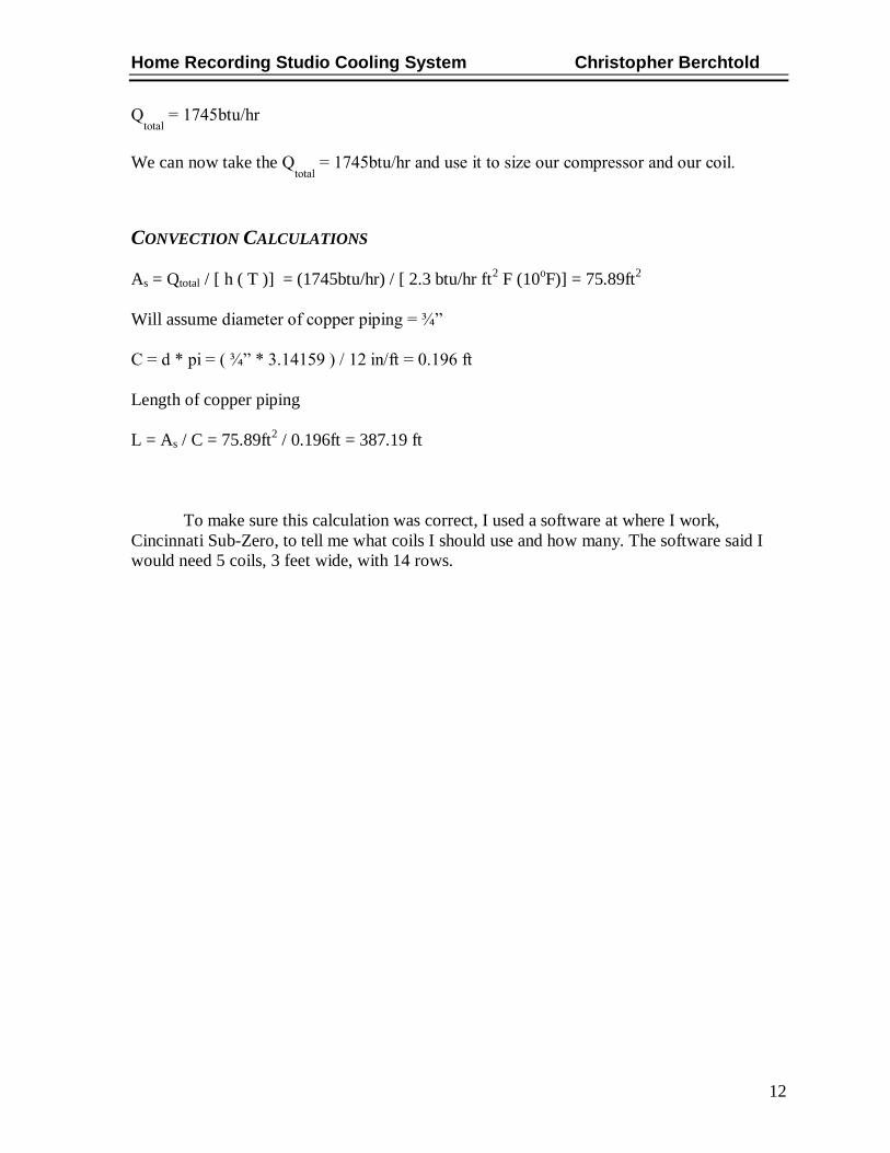
Qtotal
= 1745btu/hr
We can now take the Qtotal
= 1745btu/hr and use it to size our compressor and our coil.
CONVECTION CALCULATIONS
As = Qtotal / [ h ( T )] = (1745btu/hr) / [ 2.3 btu/hr ft2 F (10
oF)] = 75.89ft
2
Will assume diameter of copper piping = ¾”
C = d * pi = ( ¾” * 3.14159 ) / 12 in/ft = 0.196 ft
Length of copper piping
L = As / C = 75.89ft2 / 0.196ft = 387.19 ft
To make sure this calculation was correct, I used a software at where I work,
Cincinnati Sub-Zero, to tell me what coils I should use and how many. The software said I
would need 5 coils, 3 feet wide, with 14 rows.

Home Recording Studio Cooling System Christopher Berchtold
13
FABRICATION AND ASSEMBLY
Most of the components I would need were already in this air conditioner show in Figure
8. The Bill of Materials and list of components can be found in Appendix .The face plate was
removed and so were the controls. The expansion device and the evaporator coil were
removed as well. All that was left was the condenser coil, condenser fan, the compressor, and
the electrical components.
Figure 8 – GE In-Window Air Conditioner
A sheet metal piece was bent and added on the front of the unit for the 2gpm pump
and the anti-freeze reservoir. A heat exchanger was acquired from work and was mounted to
a wood block, as seen in Figure 9.
Figure 9 – Right Side of Unit

Home Recording Studio Cooling System Christopher Berchtold
14
A liquid sight glass and expansion valve were also acquired from work and installed
in between the heat exchanger and the condenser coil. The liquid sight glass can be seen on
the left side of Figure 10, and the expansion valve can be seen in the center. For water tight
copper pipe brazing, the unit was taken to Cincinnati Sub-Zero and a refrigeration shop work
was paid off the clock to do this.
Figure 10 – Top of Unit
Piping ran from the anti-freeze reservoir to the pump, to the heat exchanger, out to the
coil, and returning back to the reservoir. As seen in Figure 11, ½” brass couplings and hose
barbs were used to easy connect and disconnect the hoses to the unit.
Figure 11 – Front of Unit

Home Recording Studio Cooling System Christopher Berchtold
15
A metal cover was then made using 22ga steel. Cut outs were made in the cover for
the refrigeration lines, tank access, the controller, and the pump switch. When the unit is
plugged in, power will be given to the controller. When the switch is turned “On” power will
be given to the compressor and condenser fan, and the controller acts as a switch turning
them on and off.
Figure 12 – Final Assembly
The five coils were brazed together (as seen in Figure 13), again by a refrigeration
shop worker from Cincinnati Sub-Zero. They were then mounted to the top of the test
chamber.
Figure 13 – Convection Coils

Home Recording Studio Cooling System Christopher Berchtold
16
TESTING AND PROOF OF DESIGN
TESTING
The testing methods were minimal. After the assemblies were complete, a test chamber
was built. It consisted of two parts: a bottom part that was 4ft by 4ft by 4ft, and a top part that
was 4ft by 4ft by 3ft. These parts were made out of a wooden frame and covered with RV ½”
insulation. The coil was installed to the top part using (2x) 2 by 4’s across the top. The top
piece was then set on top of the bottom piece, bolted together, and hoses were run from the
coil to the unit, as seen in Figure 14.
Figure 14 – Test Chamber
Then a thermal couple was placed inside the chamber and another outside of the
chamber. A lamp was placed in the chamber as a heating load. And decibel reader was also
placed inside and outside of the chamber.

Home Recording Studio Cooling System Christopher Berchtold
17
PROOF OF DESIGN
The temperature within the test chamber was 65OF and reached it in only 20min. The
decibel reader read 62dba outside of the chamber and 40dba within the chamber, but all of it
was coming from the unit itself. So a microphone was placed inside the chamber and
measured the volume. Acoustic insulation was placed next to the microphone, in between it
and the unit to try and get a truer reading of the coil. It read that the coil volume is between -
39dB and -42dB, which meets the requirements. The noise was a dripping sound within the
coil; air was within the system. The reason for this was because I ran out of anti-freeze. If
there was more anti-freeze in the reservoir, the air would be taken out of the system, and the
dripping sound would also be taken out.

Home Recording Studio Cooling System Christopher Berchtold
18
PROJECT MANAGEMENT
SCHEDULE
The project schedule begins on November 23, 2012 with the completion of Concept
Sketches. The project timeline covers 22 weeks and ends April 17, 2013 with the
presentation of the final report. The Key Dates can be seen in Table 3, full schedule can be
seen in Appendix E.
Table 4 - Key Dates
Key Dates
Concept Sketches 11/23/12
3D Model Design 01/07/13
Finalize Design 01/16/13
Purchase Components 02/08/13
Final Assembly 02/18/13
Final Testing 03/12/13
Design Demonstration 04/17/13
BUDGET
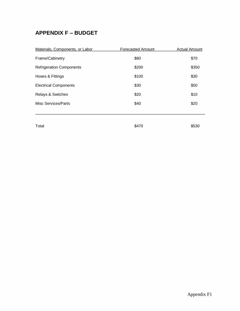
The Forecasted Amount, as seen in Table 4, shows how much was budgeted to build
one prototype of this system. The Actual Amount will be added at the finalization of the
project.
Table 5 - Budget
Materials, Components, or Labor Forecasted Amount Actual Amount
Frame/Cabinetry $80 $70
Refrigeration Components $200 $350
Hoses & Fittings $100 $30
Electrical Components $30 $50
Relays & Switches $20 $10
Misc. Services/Parts $40 $20
Total: $470 $530

Home Recording Studio Cooling System Christopher Berchtold
19
REFERENCES
1. Whittam, George. [interv.] Christopher Berchtold. Cincinnati, September 10, 2012.
2. Pridiom 24000 BTU Ductless Air Conditioner. Mini Split Warehouse. [Online] [Cited: 09
28, 2012.]
http://www.minisplitwarehouse.com/index.aspx?pageid=315964&prodid=4957478.
3. AP13000W - EdgeStar 13,000 BTU Whisper Quiet Air Conditioner. EdgeStar. [Online]
[Cited: 09 30, 2012.] http://www.edgestar.com/EdgeStar-13000-BTU-Whisper-Quiet-
Portable-Air-Conditioner-White/AP13000W,default,pd.html?cgid=Home_Air_Quality-
Portable_Air_Conditioners.
4. WhisperRoom Sound Booth Models. WhisperRoom Inc. [Online] [Cited: 10 01, 2012.]
http://www.whisperroom.com/sound-booth-models.php.
5. Warner, Doug. [interv.] Christopher Berchtold. Cincinnati, September 15, 2012.

Appendix A1
APPENDIX A – RESEARCH
Interview with George Whittam, Owner and Founder of ElDorado Recording
Services.
He is a 1997 Virginia Tech Grad with a Bachelor’s in Music and Audio
Technology, and a Minor in Communications.
Possible areas of innovation in Studio Recording: Using a cooling system
where the area that is being cooled has no moving parts, and any moving parts
(if required for the system) to be outside of the room.
Felt that my project is one that is needed, for when the recording space gets too
hot, the voice over worker becomes distracted by it, makes it incredibly hard to
work. Doesn’t know of any products on the market that completely satisfies the
cooling needs of the voice over worker.
Important to look up and study: Ductless Air Conditioning Systems and
Whisper Rooms.
Interview with Doug Warner, Long Narration Reader and Advertisement VO
He has had Voice Over training with Creative Voice Development Group,
LLC specialized in “Conversational Copy Reading and Delivery.”
Possible areas of innovation in Studio Recording: Can’t have pipes running
through walls for not all VOs are able to (some might live in apartments,
renting, etc.), and to have it removable if the VO moves and wants to take it
with them.
Important to remember: not all recording spaces VOs use are enclosed rooms.
His recording space is a sectioned off part of his room, using a corner and 2
large sheets of Auralex Foam. What I’m making should be able to mount
anywhere, not to a specific location (i.e. just a closet).

Appendix A2
Pridiom Single Zone Ductless Split Air Conditioner With
Heat Pump 24,000 BTU 208/230 VOLT
Inverter ductless air conditioners provide consumers with
cooling and heating solutions that are environmentally friendly
utilizing R410A refrigerant. Conserve energy by cooling or
heating only the spaces where you are. Inverter heat pump
technology constantly adjusts output to maximize comfort and
minimize energy cost. Includes remote control for ease of
operation. Features dehumidification mode, auto swing louvers,
auto-restart, sleep mode and low ambient operation.
Temperature display on indoor unit. Installation kit includes
25’L line set, 25’L connecting wire, 7’L condensate tubing and
wall sleeve.
Price: $1949.99
Problems: Unit is too
large for the space used
for recording (which is
usually 4’ X 4’ X 7’). The
cooling power coming
from it is meant for a large
room, not a closet space.
With the fans forcing air
out of the unit into the
space, it is much louder
than desired.
http://www.minisplitwarehouse.com/index.a
spx?pageid=315964&prodid=4957478
09/28/12

Appendix A3
EdgeStar 13,000 BTU Whisper Quiet Portable Air
Conditioner
This particular portable air conditioner is unlike other units in
that it operates with considerably lower noise levels. But don’t
let that fool you, as it uses 13,000 BTU power to effectively cool
rooms as big as 475 sq. ft. in size. This combination makes it
ideal for any application, including nurseries, bedrooms, offices,
and other areas where disturbance must be kept to a minimum.
Additionally, the EdgeStar AP13000W can supply any space
with cooling comfort all day for about $1.10, making it not only
one of the quietest but also most energy-efficient units available.
Price: $799.99
Problems: Even though
it is a “quiet” A/C unit,
personal experience from
Voice Over people have
told me that it is still
about -30dB to -35dB.
The noise floor for a
recording (when there is
nobody talking into the
mic) should read between
-50dB and -60dB. Also,
bit of an overkill, cooling
a space of 475 sq ft, when
VO’s only have a 16-25
sq ft area that needs to be
cooled.
http://www.edgestar.com/EdgeStar-13000-BTU-Whisper-Quiet-Portable-Air-
Conditioner-White/AP13000W,default,pd.html?cgid=Home_Air_Quality-
Portable_Air_Conditioners
09/30/12

Appendix A4
Whisper Room with Ventilation Package
Standard WhisperRoom™ Ventilation Systems are quiet.
However, the airflow noise is still slightly audible inside of a
WhisperRoom™ sound isolation booth. This noise can be
eliminated by the installation of a VSS. The number of VSS
units needed depends on the size of the WhisperRoom™ model.
One VSS is required for each Standard Ventilation System. Each
VSS consists of two additional exhaust ducts, with hoses and
adapters, linked in-line between the standard exhaust duct and
the remote fan unit (RFU).
Price: $4,579.99
Problems: The air
conditioning system for
the Whisper Room is as
quiet as any A/C unit can
get, because it was
designed for Home Studio
Recording, but the air
flow can still be heard
slightly. Also, the low fan
speed and design of the
ductwork generate low
tones that the microphone
still picks up, but Voice
Over people just deal
with it in any way they
can. Some turn off the
system (but then it gets
hot), and some block off
the vent with acoustic
foam with holes in it (and
again, gets hot).
I have searched for bladeless air conditioners and for convection air conditioners, and have
found nothing. The only kind of convection unit I have found is for heaters, such as a home
radiator heater. The only systems that I have to go off of are the so called “silent” air
conditioning systems. But from what I have been told by people in the voice over industry,
they are quiet for a normal home, but for a small recording space, they’re too overpowered
and too loud.
I have also found that the way of measuring for the noise floor in a recording. When the
audio is normalized, which means the highest peak becomes zero, the points at which nobody
is talking, it should read between -50dB and -60dB. This is the standard for any home studio;
recording studios can actually reach -70dB.
http://www.whisperroom.com/sound-booth-
models.php
10/01/12

Appendix B1
APPENDIX B – SURVEY WITH RESULTS
HOME RECORDING STUDIO COOLING SYSTEM
CUSTOMER SURVEY
This survey is for customer feedback. With it, the HRSCS will be able to conform to the
features that are seen to be most desirable. Thank you.
How important is each feature to you for the design of a new Home Recording
Studio Cooling System?
Please circle the appropriate answer. 1 = low importance 5 = high importance
Avg
Safe 1 2 3 (2) 4 (3) 5 N/A 3.6
Extremely Quiet 1 2 3 4 5 (5) N/A 5.0
Fast to Reach Temp 1 2 3 (1) 4 (4) 5 N/A 3.8
Easy to Install 1 2 3 (1) 4 (1) 5 (3) N/A 4.4
Able to be Moved 1 2 (1) 3 (3) 4 (1) 5 N/A 3.0
Easy to Use 1 2 3 4 (3) 5 (2) N/A 4.4
Durable 1 2 3 (2) 4 (3) 5 N/A 3.6
Compact 1 2 3 (2) 4 (3) 5 N/A 3.6
Easy to Adjust 1 2 3 (1) 4 (2) 5 (2) N/A 4.2
Is Energy Efficient 1 2 3 4 (2) 5 (3) N/A 4.6
Reliable 1 2 3 4 (2) 5 (3) N/A 4.6
Affordable 1 2 3 4 (1) 5 (4) N/A 4.8
How satisfied are you with the current Silent Cooling Systems?
Please circle the appropriate answer. 1 = very UNsatisfied 5 = very satisfied
Avg
Safe 1 2 3 (3) 4 5 N/A (2) 1.8
Extremely Quiet 1 2 3 4 (2) 5 N/A (3) 1.6
Fast to Reach Temp 1 2 3 (1) 4 5 (1) N/A (3) 1.6
Easy to Install 1 2 3 (3) 4 5 N/A (2) 1.8
Able to be Moved 1 2 3 (3) 4 5 N/A (2) 1.8
Easy to Use 1 2 3 (2) 4 (1) 5 N/A (2) 2.0
Durable 1 2 3 (2) 4 (1) 5 N/A (2) 2.0
Compact 1 2 3 (1) 4 (1) 5 (1) N/A (2) 2.4
Easy to Adjust 1 2 3 (3) 4 5 N/A (2) 1.8
Is Energy Efficient 1 2 3 (1) 4 (1) 5 N/A (3) 1.4
Reliable 1 2 3 (1) 4 (2) 5 N/A (2) 2.2
Affordable 1 2 3 4 (3) 5 N/A (2) 2.4
How much would you be willing to pay for this product? $50, $100, $100-$200 (1),
$200-$500 (3), $500-$1000 (1),
$1000-$2000

Appendix C1
APPENDIX C – QUALITY FUNCTION DEPLOYMENT
Siz
e
Sta
ndard
Com
ponents
Weig
ht
Mate
rial
Manufa
ctu
rability
Cooling A
rea
Insta
llation T
ime
Cooling T
ime
Coil T
em
pera
ture
Custo
mer
import
ance
Desig
ner's M
ultip
lier
Curr
ent
Satisfa
ction
Pla
nned S
atisfa
ction
Impro
vem
ent
ratio
Modifie
d I
mport
ance
Rela
tive w
eig
ht
Rela
tive w
eig
ht
%
Extremely Quiet 3 3 9 3 5.0 1.1 1.6 5 3.1 17.2 0.25 25%
Affordable 3 9 9 9 4.8 1.0 2.4 5 2.1 10.0 0.15 15%
Easy to Install 9 3 3 9 4.4 1.0 1.8 4 2.2 9.8 0.14 14%
Easy to Use 1 3 4.4 1.0 2.0 4 2.0 8.8 0.13 13%
Fast to Reach Quoted Temp. 3 9 9 9 3.8 1.1 1.6 4 2.5 10.5 0.15 15%
Safe 1 3 1 1 1 3.6 1.0 1.8 3 1.7 6.0 0.09 9%
Able to be Re-installed Easily 3 1 3 3 3.0 1.1 1.8 3 1.7 5.5 0.08 8%
Abs. importance 2.07 2.95 0.60 2.77 1.33 1.87 1.54 3.67 2.24 19.0 67.7 1.0 1.0
Rel. importance 0.11 0.15 0.03 0.15 0.07 0.10 0.08 0.19 0.12 1.0
Home Recording Studio Cooling System9 = Strong3 = Moderate1 = Weak

Appendix D1
APPENDIX D – PRODUCT OBJECTIVES
Product Objectives
Home Recording Studio Cooling System
The following is a list of product objectives and how they will be obtained. The product
objectives will focus on cooling the recording space in a home studio (which is generally 4’ x
4’ x 7’) and be completely silent.
8. Extremely Quiet 25%
a. No moving parts in the area being cooled
i. No forced air or noise from a fan
ii. Reducing noise below -40 dB
b. Using copper tubing on ceiling of area being cooled
i. Cooling thru convection
c. Cooling System to be hung in windowsill
i. Parts that make noise being outside to reduce noise in the work space
9. Fast to Reach Quoted Temp. 15%
a. Refrigeration & Convection Calculations
10. Affordable 15%
a. Between $200 and $500
11. Easy to Install 14%
a. Customer to be able to install unit
i. To be installed such as a modern in-window AC Unit
b. Single tool installation
c. Fewer loose parts to attach
12. Easy to Use 13%
a. On/Off switch
b. Varying levels of cooling
i. From 60OF down to 40
OF
13. Safe 9%
a. All components shielded from weather and climate
b. All refrigeration lines soldered water tight
c. Water tight connecters and hosing between window unit and coil
d. Window unit to be secured safely to window
e. Coil to be safely secured to ceiling of the cooling area
14. Able to be Re-installed Easily 8%
a. Hoses connecting coil and window unit able to be disconnected
b. Window unit able to be removed from the window
c. Coil on ceiling able to be removed easily and safely

Appendix E1
APPENDIX E – SCHEDULE
TASKS Oct
14
-20
Oct
21
-27
Oct
28
- N
ov
3
No
v 4
- 1
0
No
v 1
1 -
17
No
v 1
8 -
24
No
v 2
5 -
Dec
1
Dec
2 -
8
Dec
9 -
15
Dec
16
- 2
2
Dec
23
- 2
9
Dec
30
- J
an 5
Jan
6 -
12
Jan
13
- 1
9
Jan
20
- 2
6
Jan
27
- F
eb 2
Feb
3 -
9
Feb
10
- 1
6
Feb
17
- 2
3
Feb
24
- M
ar 2
Mar
3 -
9
Mar
10
- 1
6
Mar
17
- 2
3
Mar
24
- 3
0
Mar
31
- A
pr
6
Ap
r 7
- 1
3
Ap
r 1
4 -
20
Ap
r 2
1 -
27
Work on First Draft 7
12
Work on Final Report for Seminar 16
20
Concept sketches to advisor 23
27
Proof of Design Agreement 23
27
Refrigeration Flow Diagram 5
7
Refrigeration BOM 7
6
Electrical Schematic 12
20
Electrical BOM 14
6
Cabinet Design & BOM 7
6
Design Report 16
31
Oral Design Presentation 16
31
Purchase / Manufacture Parts 8
3
Assembly 18
3
Test/Modifications 12
3
Proof of Design to Advisor 15
Tech Expo 4
4
Work on Final Report 24
Oral Project Presentation 17
Christopher BerchtoldHome Recording Studio
Cooling System
Appendix F1
APPENDIX F – BUDGET
Materials, Components, or Labor Forecasted Amount Actual Amount Frame/Cabinetry $80 $70
Refrigeration Components $200 $350
Hoses & Fittings $100 $30
Electrical Components $30 $50
Relays & Switches $20 $10
Misc Services/Parts $40 $20
Total $470 $530

Appendix G1
APPENDIX G – BILL OF MATERIALS
ITEM I.D. NO. QTY. DESCRIPTION MANUFACTURERMFG' PART NO. UNIT PRICE TOTAL PRICE
48022 1 PUMP LITTLE GIANT $112.05 $112.05
00902 1 BODY, TEV SPORLAN EQ-ODF $23.45 $23.45
P- 1 CARTRIDGE SPORLAN QC-00 $0.00 $0.00
02534 1 THERMAL ASSY SPORLAN KT-45-ZN $12.28 $12.28
03040 1 SIGHT GLASS SPORLAN SA-12S $5.79 $5.79
P- 1 AIR CONDITIONING UNIT G.E. AET05LQ $100.00 $100.00
$0.00
$0.00
FITTINGS & MISC PARTS $0.00
17320 1 COUPLING, 3/8" $0.37 $0.37
18011 1 TEE, 1/4" $3.33 $3.33
18300 1 TEE, REDUCING, 3/8" x 3/8" x 1/4" $5.20 $5.20
05050 2 SERVICE PORT $2.37 $4.74
18106 2 REDUCER FITTING, 3/8" x 1/4" $1.09 $2.18
18110 1 REDUCER FITTING, 1/2" x 3/8" $1.23 $1.23
18500 1 ELBOW, 1/4" $1.53 $1.53
08075 2 HOSE BARB, 1/2NPT x 1/2" HOSE $1.13 $2.26
$0.00
$0.00
COILS $0.00
00332 5 FIN COIL HEATCRAFT $56.01 $280.05
$0.00
$0.00
$554.46
BILL OF MATERIALS
==================================================================================================================================================
===========================================================================================================================================================================================

Appendix H1
APPENDIX H – REFRIGERATION FLOW DIAGRAM