home security sensor system using atmel avr … security sensor system using atmel avr... · home...
TRANSCRIPT

HOME SECURITY SENSOR SYSTEM USING
ATMEL AVR MICROCONTROLLER
LIM BOON HOI
This project is submitted in partial fulfillment of
the requirements for the degree of Bachelor of Computer Science with Honours
(Network Computing)
Faculty of Computer Science and Information Technology
UNIVERSITI MALAYSIA SARAWAK
2006
ii
ACKNOWLEDGEMENT
First and foremost, I would like to send my utmost gratitude to the Faculty of
Computer Science and Information Technology, University Malaysia Sarawak for giving me
an opportunity to do this final year project. I would also like to thank and acknowledge the
contribution of my supervisor, Dr. Tan Chong Eng for guiding me through in this final year
project. He has given full support and motivation for my final year project. And to Dr. Wang
Yin Chai for being the coordinator of this final year project where he has also given guidance
to us. I would like to thank my family for their encouragement and support. Lastly but not
least, to everyone who has helped me in the final year project and bringing the best memories
throughout the processes of completing project.
iii
ABSTRACT
The AVR Flash Microcontroller based Home Security Sensor System is an automated
home alarm system with built-in centralized security monitoring system prototyped using the
Atmel STK500 starter kit. The system is able to monitor the house by displaying the
information of the current condition of the house and trigger the alarm when the house is
being broken in. The development of this home security sensor system involves both
hardware and software components. The hardware interface is used to connect all the sensors
in the model of the house together with a display panel. The hardware circuit design is built
on the AT90S8515 microcontroller. The software program developed is used to control all the
functions of the system and it is developed using the AVR studio. The AVR studio is a
specific tool for Atmel based assembly program development and debugging. The Home
Security Sensor System can be further extended to become more comprehensive in the future.

iv
ABSTRAK
AVR Flash Microcontroller based Home Security Sensor System merupakan satu
sistem alarm rumah automatik yang mempunyai pengawal keselamatan berpusat dengan
menggunakan Atmel STK500 starter kit sebagai landasan asal. Sistem ini boleh mengawal
rumah dengan memaparkan keadaan semasa dalam rumah dan membunyikan loceng apabila
rumah dicerobohi. Pembangunan sistem rumah keselamatan ini melibatkan pembinaan
fizikal/perkakasan dan perisian. Antaramuka fizikal digunakan untuk menyambungkan
sensors ke rumah dengan papan pemapar. Fizikal litar direka di atas AT90S8515
microcontroller. Bagi pembangunan pengaturcaraan, perisian pula digunakan untuk
mangawal semua fungsi dalam sistem ini. Pembangunan perisian ini menggunakan AVR
studio. AVR Studio ialah sebuah perkakasan bagi Atmel yang berdasarkan pengaturcaraan
assembly. The Home Security Sensor System berpontensi untuk dibangunkan dengan lebih
canggih lagi.

v
TABLE OF CONTENTS
ACKNOWLEDGEMENT ii
ABSTRACT iii
ABSTRAK iv
TABLE OF CONTENTS v
LIST OF FIGURES x
LIST OF TABLES xii
CHAPTER 1: AN OVERVIEW
1.0 Introduction 1
1.1 Problem Statement 2
1.2 Objective 3
1.3 Methodology 3
1.3.1 Phase 1: Planning 3
1.3.2 Phase 2: System Analysis 4
1.3.3 Phase 3: System Design 4
1.3.4 Phase 4: System Implementation and Integration 5
1.3.4.1 Stage 1: Hardware Implementation 5
1.3.4.2 Stage 2: Software Implementation 5
1.3.4.3 Stage 3: System Integration 5

vi
1.3.5 Phase 5: System Testing and Evaluation 6
1.4 Scope of Project 6
1.5 Significance of Project 6
1.6 Expected Outcome 7
1.7 Summary 7
CHAPTER 2: LITERATURE REVIEW
2.0 Introduction 8
2.1 Background Study 9
2.1.1 The Operation of Security Alarm 9
2.1.2 The Operation of Magnetic Sensor 10
2.1.3 The Operation of Motion Detector 10
2.1.4 The Operation of Vibration Detector 12
2.1.5 How the Burglar Breaks into a House 12
2.2 Reviews on Existing Security System and Sensors 13
2.2.1 NAPCO Gemini P816 Security Panel 13
2.2.2 Home Alarm system 14
2.2.3 48-Zone-Customizable Caddx Security System 16
2.2.4 DDT-15 New Generation Professional Diffused Spectrum Analysis
Detector with PIR & MW Dual-tech Novel
17
2.2.5 Comparing the Features of the Existing Systems 19

vii
2.3 Microcontroller 20
2.3.1 Atmel AVR Microcontroller 20
2.3.2 Comparison of Microcontroller 22
2.4 Summary 23
CHAPTER 3: REQUIREMENT ANALYSIS AND SYSTEM DESIGN
3.0 Introduction 24
3.1 Requirement Analysis 24
3.1.1 Physical Hardware Requirement 24
3.1.1.1 Atmel AVR® STK500 Flash Microcontroller Starter Kit 25
3.1.1.1.1 STK500 Switches and LED 27
3.1.1.1.2 STK500 Port connection 29
3.1.1.1.3 STK500 Jumper 30
3.1.1.1.4 STK500 Target Socket Section 30
3.1.1.1.5 AT90S8515 Microcontroller 32
3.1.1.2 Sensors 37
3.1.1.2.1 Magnetic Sensor 37
3.1.1.2.2 Vibration Sensor 37
3.1.1.2.3 Passive Infrared Motion Sensor 38
3.1.1.3 Display Panel and Siren 39
3.1.1.3.1 Control Panel 39

viii
3.1.1.3.2 Keypad 39
3.1.1.3.3 Siren 39
3.1.2 Communication Port Requirement Analysis 40
3.1.3 Software Requirement Analysis 40
3.2 System Design 41
3.2.1 Hardware Interface Design 41
3.2.1.1 Security Sensor System Circuit Design Layout 42
3.2.2 Security Sensor System Flow Chart 46
3.3 Summary 47
CHAPTER 4: IMPLEMENTATION AND TESTING
4.0 Introduction 48
4.1 Hardware Interface Implementation 48
4.1.1 Home Sensors Implementation 48
4.1.2 Display Panel Implementation 50
4.2 Software Implementation 52
4.3 Integration of the System 54
4.4 System Testing and Evaluation 55
4.5 Summary 55

ix
CHAPTER 5: CONCLUSIONS AND FUTURE WORK
5.0 Introduction 56
5.1 Conclusions 56
5.2 Future Work 57
REFERENCES 58

x
LIST OF FIGURES
Page Number
Figure 2.1 The Magnetic sensor 10
Figure 2.2 Motion detector- Radar-based motion detectors 11
Figure 2.3 Vibration Sensor 12
Figure 2.4 How burglar breaks into the house 13
Figure 2.5 NAPCO Gemini P816 Security Panel 14
Figure 2.6 Home Alarm System 15
Figure 2.7 48-Zone-Customizable Caddx Security Systems 17
Figure 2.8 DDT-15 New Generation Professional Diffused
Spectrum Analysis Detector with PIR & MW Dual-tech
Novel
18
Figure 2.9 Atmel AVR STK500 Programmers and Starter Kit 21
Figure 3.1 Physical Hardware Components That Required In This
Security Sensor System
25
Figure 3.2 The connections to the STK500 25
Figure 3.3 The STK500 Starter Kit Schematic 26
Figure 3.4 The special Function and Status Indication LEDs 27
Figure 3.5 The STK500 Components 28
Figure 3.6 The LED and Switches Schematic 28
Figure 3.7 The General Pinout of I/O Port Headers 29
Figure 3.8 The I/O Ports Schematic 29
Figure 3.9 The default Jumpers Setting 30
Figure 3.10 The AT90S8515 AVR RISC Architecture 33
Figure 3.11 The AT90S8515 Data Block diagram 34
Figure 3.12 Memory Map 35
Figure 3.13 Pin Configurations 35

xi
Figure 3.14 Print screen of AVR studio 41
Figure 3.15 Logical Structure of the Security Sensor System 42
Figure 3.16 Display panel with LED connected to the Atmel
STK500’s port B.
43
Figure 3.17 Home Security Sensor System design layout connected
to the Atmel STK500’s port D.
44
Figure 3.18 Home Security Sensor System circuit design layout 45
Figure 3.19 Overall circuit layout of the home security sensor
system
45
Figure 3.20 The Security Sensor System Flow Chart 46
Figure 4.1 A house model with switches (sensors) 49
Figure 4.2 The connection pins of each wire to 10-pin cable at
port D
49
Figure 4.3 The 8-N-1 format 49
Figure 4.4 The connection of the house model to the STK500
starter kit through Port D
50
Figure 4.5 Display panel with LED 50
Figure 4.6 The connection pins of each wire to the 10-pin cable at
port B
51
Figure 4.7 The connection of the display panel to the STK500
starter kit through Port B
51
Figure 4.8 Hardware connection of the system 54

xii
LIST OF TABLES
Page Number
Table 2.1 Features of NAPCO Gemini P816 Security Panel 14
Table 2.2 Features and benefits of Home Alarm System 15
Table 2.3 features of 48-Zone-Customizable Caddx Security
System
17
Table 2.4 Features of DDT-15 New Generation Professional
Diffused Spectrum Analysis Detector with PIR & MW
Dual-tech Novel
18
Table 2.5 Monitored alarm systems and alarm monitoring from
national alarm companies compared
19
Table 2.6 Features of Atmel AVR STK500 22
Table 2.7 Microcontroller Comparisons 23
Table 3.1 The description of jumpers 30
Table 3.2 AVR Socket 31
Table 3.3 The detail information about AT90S8515 features 32
Table 3.4 Pin Description Summary 36
Table 4.1 The Source code of the home security sensor system
prototype
53

1
CHAPTER 1
AN OVERVIEW
1.0 Introduction
In this fast and rapid growth of information technology era, most of the people
nowadays can live in comfort zone. People can get whatever they want easily and go
wherever they want.
The criminal rate is increasing day by day. Robbery, burglary, and rape are happening
everywhere. People are afraid of walking alone, living in frighten, no peace in their heart
when they go out or traveling, and hence people reduce their out door activities. From a
survey that done by the National Crime Prevent Council (NCPC), most of the people feel safe
when they are in the house, in workplace and in the community [NCPC, 2001]. Most of the
people nowadays are preferred to stay at home. Since Internet is widely used and everywhere,
by having Internet at home, people think that they do no need to go out to socialize with other
people.
Crime rates continue to increase nationwide. Mark Jarrett from British Gas Home
Security said that the crime statistic shows that 18.2% of the households with no security
system were burgled compared to there was only 0.7% out of 2% household with high level
of security system being entered [Centrica, 2004]. Some people may believe that locking all
the doors and windows, using hardwood or metal for outside doors and door frame and so on

2
will make the house a safer place. In reality, these are still not safe enough! Burglars still can
break into the house.
The National Crime Prevent Council (NCPC) suggests the homeowner to install an
alarm system for summoning emergency help [NCPC, 2001]. When the house is broken in,
the alarm system will be triggered and alert the homeowner or neighbours. Therefore,
homeowner or neighbours can take necessary reactions.
Even though, a security system cannot give 100% guarantee that the house is safe, but at
least it managed to reduce the crime rate.
1.1 Problem statement
Due to the increase in crime rate, most of the houses today are lacking of a security
system to protect the home. A good lock for doors and windows is just not enough. The
National Crime Prevent Council (NCPC) suggests the homeowner to install the alarm system
[NCPC, 2002].
A security systems that only trigger the alarm is just not good enough, it only can get
attention from the homeowner and neighbours. Sometimes it may scare the burglar, but most
of the time they will not afraid of the alarm.
Most of the homeowners would like to know the current state of their house even
before the alarm system is triggered. The lack of features such as monitoring in an automated
alarm system, will never give a total peace of mind to the home owners.

3
1.2 Objective
The purpose of this project is to develop a security sensor system for smart home.
The project aims to:
i. Create an automated home alarm system with monitoring feature built-in based on
the Atmel AVR STK500 starter kit.
ii. Create an alarm system that is able to monitor the house by displaying or providing
the information of the current condition of the house (centralized security monitoring
system).
iii. Create an alarm system that is able to trigger the alarm and send a signal to
homeowner when the security system has been triggered or detecting moving objects
like human in the house.
1.3 Methodology
In order to complete this project, several phases are needed. This project starts with
planning the system. Then, analysis and design of the system. Finally, it is implemented and
tested.
1.3.1 Phase 1: Planning
In this phase, feasibility study will be conducted. It involves identifying the project
goals, objectives, problems, project contributions, and system requirements.
The methods to be adopted by the security sensor system in the planning phase are:

4
Literature reviews on the existing security systems and study their background to
understand more about the security sensor features and functionality.
Exploration on how the Atmel AVR STK500 microcontroller works and understands the
AVR studio by testing some of the example assembly programs.
1.3.2 Phase 2: System Analysis
In this system analysis phase, analyze and specify system requirements, finalize
systems objectives, and define system functionality will be done. The information gather in
phase 1 during the feasibility studies will be used to further define the system goals and
functions.
The methods to be adopted by the security sensor system for this phase 2 are:
Analyzing the existing security systems and comparison among the systems which
similar to the proposed security sensor system.
Performing search for appropriate hardware required by the system.
Analyzing of hardware and software requirements for the system such as sensor circuits
and assembly language to use.
1.3.3 Phase 3: System Design
At this phase, a detailed implementation plan will be developed, revise cost estimation,
and produces the Systems Design Specifications.
The methods to be adopted by the security sensor system for this design phase are:

5
Design and propose a standalone security system specifically for home use.
Sensor circuit design
Design the logical flow of the system.
1.3.4 Phase 4: System Implementation and Integration
In this phase, the security sensor system will be divided into three stages. Therefore,
developer can be more focus on a small module and become more effective compare to doing
the whole system at once. Besides that, it also helps to refine the vital components of the
system that needs more time to develop.
1.3.4.1 Stage 1: Hardware Implementation
Implementing, setup and configuring all the sensors and come out with a
functional prototype. This prototype will be developed based on the sensor
circuits’ design that was defined in the previous phase.
1.3.4.2 Stage 2: Software Implementation
Program will be developed to implement all the applications that have been
proposed for the security system by using assembly language.
1.3.4.3 Stage 3: System Integration
Integrating the hardware and software systems to produce the final system.
Solve the system errors or hardware errors once integrate.

6
1.3.5 Phase 5: System Testing and Evaluation
After the system is completely built functionality and usability testing will be carried
out. Feedbacks gather from the tests will be used to further improve the final system.
Documenting process will also be carried out in line with the testing and evaluation.
1.4 Scope of Project
This prototype system is designed only for home use. The security sensors will be
implemented by homeowner in their house. This system only includes the basic security
applications implemented using the Atmel AVR STK500 microcontroller. This system not
only can trigger the alarm when the security is breach, but also capable of performing
centralized security monitoring under normal home conditions.
1.5 Significance of Project
The significance of this project is to provide a solution to the problem faced by the
homeowner which is the security of their house. By implementing this security system in the
house, users are able to check their house condition from time to time. They can monitor their
home from a centralized location where they will know exactly which part of the house has
been broken in. This will give them additional information to plan for the actions required to
counter the break-in.
7
1.6 Expected Outcome
When this working prototype of security system is fully developed, it will be able to
trigger the alarm and alert the user at the centralized control panel when the sensor is
triggered. This system can also alert the user when the motion sensor detects any moving
object. Users can know their house conditions through the centralized control panel.
1.7 Summary
Chapter 1 gives an idea about the importance of having a security system at home. The
problem statements, objectives, methodology, and expected outcome are discussed as well in
this chapter.
8
CHAPTER 2
LITERATURE REVIEW
2.0 Introduction
Statistic showed that burglars attack homes without electronic security three times
more often than homes with a system [TCPALM Network]. Therefore, knowing how to
choose a good or suitable security system for home is important.
A good system covers the entire perimeter of your home and at least one internal trap
[TCPALM Network]. The size and layout of the home must be taken into consideration when
designing the overall system. The alarm system should be loud and clearly heard [Vivian
Capel, 1997] but also easy to use. The system chosen must also reliable and less false alarms
happen. In the Metropolitan Police area no less than 98% of the call-outs are for false alarms.
So, it is a waste of time and resources [Vivian Capel, 1997].
Basic elements of a standard system includes: a keypad, control panel, a siren, an
inside motion detector and door contacts [TCPALM Network]. And it must be linked to a
central monitoring station. Additional protection should be added to meet the individual needs
of the property being protected.
9
2.1 Background Study
Before go into the detail of the current technologies, an overview of the security alarm
and sensors will be discussed in this chapter to further the understanding of the techniques
used in the similar system.
2.1.1 The Operation of Security Alarm
Most of the security alarm systems or burglar alarms are simple electric circuit built
into an entry way. In any circuit, electricity only flow when giving the path between two
points of opposite charge. In order to turn on the electric current, it needs to close the circuit
by a using switch. In order to turn off the electricity, it needs to open the circuit.
In the security alarm system, a switch detects the act of intrusion. For example, open
or close the door and window. In a closed-circuit system, the electric circuit is closed when
the door or window is closed. This means that as long as the door is closed, electricity can
flow from one end of the circuit to the other. But if somebody opens the door, the circuit is
opened, and electricity cannot flow. This triggers the alarm. While in an open-circuit system,
opening the door closes the circuit, and electricity begins to flow. In this system, the alarm is
triggered when the circuit is completed.
The modern alarm system insert a control box inside their system in order to prevent
burglar closes the door after triggering the alarm and turn off the alarm. This control box has
its own power supply even though it hooked on the alarm circuit. It monitors the circuits and
sounds the alarm when they are closed or opened. When the alarm is triggered, the control
10
box will not cut off until someone has enters a correct security code at the connected keypad.
[HowStuffWorks]
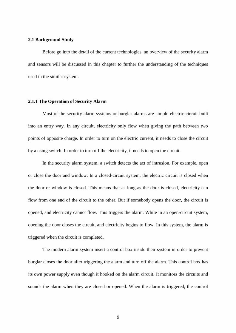
2.1.2 The Operation of Magnetic Sensor
Magnetic sensor works closely related to security alarm system. When the door or
window is closed, the magnet pulls the metal switch closed so the circuit is complete. When
you move the magnet by opening the door or window, the spring snaps the switch back into
the open position. This cuts off the current and closes the relay, then sounding the alarm.
Figure 2.1 shows examples of magnetic sensor. [HowStuffWorks]
Figure 2.1 The Magnetic sensor
2.1.3 The Operation of Motion Detector
There are several different sorts of detectors. Radar-based motion detector sends out
bursts of microwave radio energy (or ultrasonic sound waves), and then waits for the reflected
energy to bounce back. If there is nobody in front of the door, the radio energy will bounce
back in the same pattern. But if somebody enters the area, the reflection pattern is disturbed.

11
When this happens, the sensor sends a signal and the door opens. In a security system, the
sensor sends an alarm signal when the reflection pattern in a room is disturbed as shown in
Figure 2.2. [HowStuffWorks]
The motion detector emits radio
energy into a room and monitors the
reflection pattern.
If somebody disturbs the reflection
pattern, the motion detector sends an
alarm signal to the control box.
Figure 2.2 Motion detector- Radar-based motion detectors
Another type of motion detector is photo-sensor motion detector. There are two types
of components: focused light (laser beam) and light sensor. Normally, the light sensor will be
used for home. When somebody walks between the light source and the sensor, the path of the
beam is blocked briefly. The sensor registers a drop in light levels and sends a signal to the
control box. [HowStuffWorks]
Passive infrared (PIR) motion detectors are more advanced than others. These sensors
sense the infrared energy emitted by an intruder's body heat. When an intruder walks into the
field of view of the detector, the sensor detects a sharp increase in infrared energy. PIR
detectors are designed to trigger the alarm only when infrared energy levels change very
rapidly. [HowStuffWorks]
12
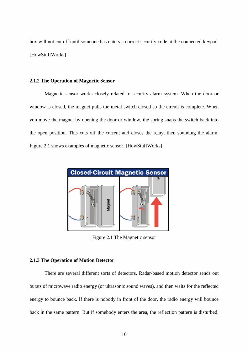
2.1.4 The Operation of Vibration Detector
These devices consist of a leaf spring suspended at its top and having a weight fixed to
its free end. At the free end is a contact that mates with another which is fixed to the case. The
pressure between the contacts, which are normally closed, is adjusted by a set-screw which
thereby sets the sensitivity of the device. Any vibration or movement will cause the contacts
to part, this will initiate an alarm. Figure 2.3 shows the components of a vibration sensor
[Vivian Capel, 1997]
Figure 2.3 Vibration Sensor
2.1.5 How the Burglar Breaks into a House
According to the National Crime Prevention Center, there are several ways for a
burglar to break into the house for example through a door, window, garage, basement and so
on. According to the statistic done by the National Crime Prevention Center, 34% of the
burglary is through the front door; followed by 23% through the first floor windows and 22%
is broken in through the back door as shown in Figure 2.4. From the survey, it can be