home septic system site evaluation and system design
TRANSCRIPT

Home Septic System
Site Evaluation
And
System Design
For
Rachel McGarity
8530 Nebraska Ave.
Toledo OH 43617
419-297-5290
Property Location:
Same As Above
Springfield Township, Lucas County
Replacement Leach Trench System
By
Nathan Wright
Geophyta, Inc.
2685 C.R. 254
Vickery, OH 43464
419-547-8538
January 13, 2017
Geoph
yta, In
c. ©
Copyright 2017 Geophyta, Inc.

To The Homeowner:
A septic system is designed based on all the information you provide and Geophyta Inc
collects at the site. It must be accurate. This information includes local soil limits and
topography, plus existing and future locations of your home, number of bedrooms, out
buildings, driveways, drinking water wells, ponds, septic systems, and property lines.
Geophyta Inc. relies on this information to construct detailed design drawings that must
meet local health department regulations before installation.
Any design changes required by the local health department to meet existing
regulations are the responsibility of Geophyta Inc.
Any information changes made by you after the initial site inspection are your
responsibility and will result in additional charges to you above the original quote for
services. These charges may include additional site inspection work, system redesign,
and resubmitted drawings.
To The Installer:
The registered installer of this septic system design is responsible for preparing an “as-
built” record, as stated in the Ohio Administrative Code Chapter 3701-29-09, Par. F
(p.32) of the “Sewage Treatment System Rules,” Ohio Department of Health, January 1,
2015. Additionally, the installer is responsible for measuring and recording distal
pressure head and float switch settings as baseline measures for future operation and
maintenance of any pressure distribution system (3701-29-15, Appendix B, Par. V(p.93)
of above referenced rules.
If the installer requests “as-built” record creation from Geophyta Inc., additional charges
will be billed to the installer by Geophyta Inc. and must be arranged prior to installation.
Geophyta Inc. must assume that any registered installer has the knowledge, equipment,
ability, and experience to properly layout, install, and create as-built drawings for any
septic system design approved by a local board of health. This includes the ability to
read detailed design prints with an associated bill of materials. For this reason, any
Geophyta Inc project supervision prior to or during installation will be billed to the
installer.
Any product substitution made by the installer that is not specifically permitted in the
design prints may result in Health Dept. disapproval and will result in additional re-
design costs billed to the installer.
Geoph
yta, In
c. ©
Copyright 2017 Geophyta, Inc.

Geoph
yta, In
c. ©
Copyright 2017 Geophyta, Inc.
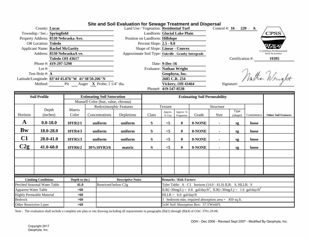
Site and Soil Evaluation for Sewage Treatment and DispersalControl #: - -
Pit Auger Probe; 1 1/4" dia.
Phone#:
Note : The evaluation shall include a complete site plan or site drawing including all requirements in paragraphs (B)(1) through (B)(4) of OAC 3701-29-08.
Vickery, OH 43464
Other Restrictive Layer >60 5xW Soil Absorption Box: 37.5'Wx60'L
Bedrock >60 3 bedroom min. required absorption area = 450 sq.ft.
Highly Permeable Material >60 HLLR = 6.0 gal/day/ft
Apparent Water Table >60 ILR(>30mg/L) = 0.8 gal/day/ft2, ILR(<30mg/L) = 1.6 gal/day/ft
2
Perched Seasonal Water Table 41.0 Restricted below C2g Tyler Table: A - C1 horizon (14.0 - 41.0) ILR: S, HLLR: S
Limiting Conditions Depth to (in.) Descriptive Notes Remarks / Risk Factors:
sg loosematrix S <5 0C2g 41.0-60.0 10YR6/2 30%10YR3/6
- sg0 0-NONE
0-NONE -
looseC1 28.0-41.0 10YR5/3 uniform uniform S <5
sg looseuniform S <5 0Bw 18.0-28.0 10YR4/3 uniform
- sg0 0-NONE
0-NONE -
loose
Type
(shape)
A 0.0-18.0 10YR2/1 uniform uniform S <5
Texture Structure
ConsistenceConcentrations Depletions Class Approx.
% Clay
Approx. %
Fragments Grade Size
Soil Profile Estimating Soil Saturation Estimating Soil Permeability
Other Soil Features
Munsell Color (hue, value, chroma)
Horizon
Depth
(inches)
Matrix
Color
Redoximorphic Features
Test Hole #: A Geophyta, Inc.
Method: X
Latitude/Longitude: 2685 C.R. 25483°44'45.876"W 41°38'50.206"N
Signature:
Phone #: 419-297-5290 Date: 9-Dec-16
Certification #:
Lot #: Evaluator: Nathan Wright
19395Toledo OH 43617
Address: 8530 NebraskaA ve. Approximate Soil Type: Oakville - Granby Intergrade
Applicant Name: Rachel McGarity Shape of Slope: Linear - Convex
OR Location: Toledo Percent Slope: 2.5 - 8.0
Position on Landform: Hillslope
Township / Sec.: Springfield Landform: Glacial Lake Plain
16 220 A
419-547-8538
County: Lucas Land Use / Vegetation: Residential Turf
Property Address: 8530 Nebraska Ave.
ODH - Dec 2006 - Revised Sept 2007 - Modified By Geophyta, Inc.
Geoph
yta, In
c. ©
Copyright 2017 Geophyta, Inc.

Subangular Blocky
Schoeneberger, P.J., Wysocki, D.A., Benham, E.C., and Broderson, W.D. (editors) 2002. Field book for describing and
sampling soils, version 2.0. Natural Resources Conservation Service, USDA, National Soil Survey Center, Lincoln, NE.
*Estimate approximate clay percentage within 5 percent Extremely Firm efi
For a more detailed explanation on describing and sampling soils, please refer to the "Field Book for Describing and Sampling Soils"
Very Firm vfi
Silty Clay sic
Clay c Extremely Flaggy XFL
Very Flaggy VFL
Very Friable vfr
Friable fr
Firm fi
Sandy Clay sc Flaggy FL
Silty Clay Loam sicl Extremely Channery XCN
Moist Consistence
Clay Loam cl Very Channery VCN Loose l
Sandy Clay Loam scl Channery
Very Fine Sandy Loam
CN
Silt si Extremely Bouldery XBY
Silt Loam sil Very Bouldery VBY
l Bouldery BY
vfsl Extremely Stony XST * The sizes Very Thin, Thin, Thick, and Very Thick, are used when
describing platy structure only. Substitute thin for fine, and thick for coarse
when describing platy structure.
vk
Fine Sandy Loam fsl Very Stony VST
Sandy Loam sl Stony
Loam
ST
Thick* tk Cloddy CDYCoarse Sandy Loam cosl Extremely Cobbly XCB
Very Thick*
Thin* tn Massive mLoamy Very Fine Sand lvfs Very Cobbly VCB
Single Grain sgLoamy Fine Sand lfs Cobbly CB
Loamy Sand ls Extremely Gravelly XGR
Very Thin* vn
Prismatic pr
Extr. Coarse ec Columnar cpr
Loamy Coarse Sand lcos Very Gravelly VGR Very Coarse vc
Very Fine Sand vfs Coarse Gravelly CGR Platy pl
Medium m sbk
Strong 3 Coarse co
Fine f Angular Blocky abk
Fine Sand fs Medium Gravelly MGR Moderate 2
Very Fine vf Granular gr
Sand s Fine Gravelly FGR Weak 1
Course Sand cos Gravelly GR Structureless 0
Texture Class Abbreviations Textural Class Modifiers Grade Size
R Hard bedrock
Soil Texture Soil Structure
Type (Shape)
C
Little or no pedogenic alteration,
unconsoilidated earthy material, soft bedrock
w Weak color or structure within B
x Fragipan characteristics
B Subsurface accumulation of clay, Fe, Al, Si,
humus; sesquioxides; loss of CaCo3;
subsurface soil structure
p Plow layer or artificial disturbance
r Weathered or soft bedrock
t Illuvial accumulation of silicate clay
E Mineral, loss of Si, Fe, Al, clay, organic
matter
g Strong gley
i Slightly decomposed organic matter
Numerical Prefixes: Used to denote
lithologic discontinuities.
b Buried genetic horizon
A Mineral, organic matter (humus)
accumulation, loss of Fe, Al, clay
d Densic layer (physically root restrictive)
e Moderately decomposed organic matter
Numerical Suffixes: Used to denote
subdivisions within a master
horizon.
O Predominantly organic matter (litter &
humus)
a Highly decomposed organic matter
*Includes glacial till
plain and end moraine
Footslope
Horizon Nomenclature
Master Horizons Horizon Suffixes Horizon Modifiers
Lake Pain Crest Complex
Beach Ridge Hillslope
Terrace Flat Concave
Flood Plain Knoll Linear
Landforms Position on Landform Shape of Slope
Upland* Depression Convex
Geoph
yta, In
c. ©
Copyright 2017 Geophyta, Inc.

Geophyta, Inc.
Owner: 8530 Nebraska Ave., Site A Min. Required Actual:
Home Size (bedrooms) 3
Water Use (120 gal/day/bedroom) 360 360
Limiting Condition PSWT
Depth To Limiting Condition (inches) 41.0
Depth To Bottom of Leach Trench (in.) 14.0
Infiltration Depth (in.) 27.0
Most Limiting Soil Texture S
Tyler Table Values
Infiltration Loading Rate (gal/day/sq. ft) 0.8 0.8
Hydraulic Linear Loading Rate (gal/day/ft) 6.0 6.0
Active Trench Bottom Width (ft)(HLLR/ILR) 7.50
Absorption Line Lengths (ft)(DDF/HLLR) 60 60.0
Leachfield Design Requirements Minimum
Required Actual
Active Absorption Area (DDF/ILR)(sq. ft.) 450
Active Absorption Area Adjusted (0.75)(sq. ft.) 337.5 360
25% Resting Absorption Area (sq.ft.) 84 180
Total Adjusted Absorption Area (sq.ft.) 422 540
Individual Trench Bottom Width (ft) 3.0 3.0
Total Trench Bottom Width (ft) 7.03 9.0
Total Number of Leach Lines 3 3
Active Leach Lines 2 2
Resting Leach Lines 1 1
Total Lineal Feet of Trench (ft) 180 180
Trench Separation Distance (ft) 6 6
Total Leachfield Width (ft) 15 15
Total Leachfield Length (ft) 60 60
In-Soil Leachfield Calculations - Gravelless Chambers
Geoph
yta, In
c. ©
Copyright 2017 Geophyta, Inc.
Drainage SwaleDitch Bottom, Center; drk. blue
Driveway
Approx. Parcel Lines; lt. blue
BM1 = 14.00' On Patio Corner
New 1500 gal Septic Tank
Gravelless Trenches.3 - 3'W x 60'L Trenches.Approx. 15' W x 60' L.
New, Relocated Sewer Main
Relative ElevationContours; 3 inch
9.95 gs 7.13 gs
13.83 gs
11.39 gs
13.17 gs
13.67 gs
9.79 tree
9.20 tree9.25 tree
7.96 tree
9.71 tree
8.56 fence
14.47 tree14.23 tree
14.00 patioNW
gaslinetelephone
NEBRASKA
8.94 gs
5.95 gs
6.15 gs6.57 gs
7.01 gs 6.76 gs
6.76 gs
8.98 gs
12.81 gs
11.28 gs
13.80 gs
6.01 tree
6.63 fence
6.30 soilA
10.85 tree
6.23 drvedge
6.55 drvedge
5.94 drvedge
11.77 newtank
6.98 tktp18in
SoilSiteA
.Geophyta Inc.
Copyright 2017
HSTS Layout - 8530 Nebraska Ave
0 50 10025 Feet
Geoph
yta, In
c. ©
Copyright 2017 Geophyta, Inc.
SCALE 1:250
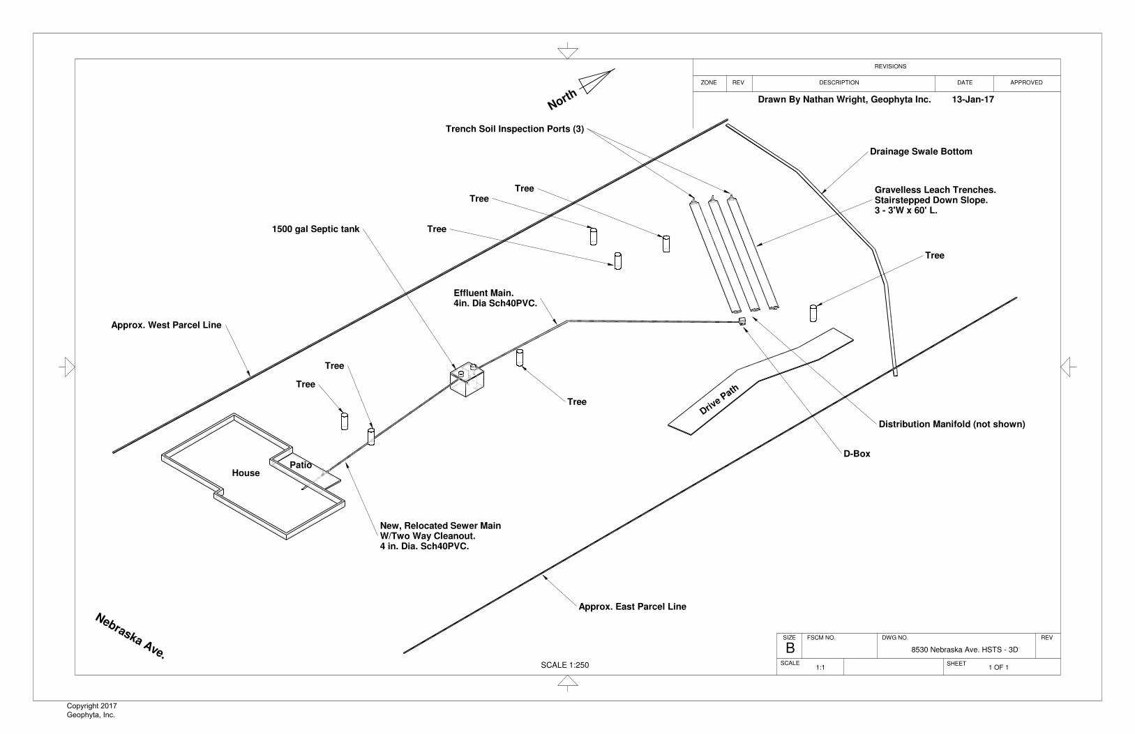
Drawn By Nathan Wright, Geophyta Inc. 13-Jan-17
Approx. East Parcel Line
Approx. West Parcel Line
HousePatio
North y
Nebraska Ave.
Drainage Swale Bottom
Tree
Tree
New, Relocated Sewer MainW/Two Way Cleanout.4 in. Dia. Sch40PVC.
1500 gal Septic tank
Tree
TreeTree
Tree
Effluent Main.4in. Dia Sch40PVC.
Distribution Manifold (not shown)
Gravelless Leach Trenches.Stairstepped Down Slope.3 - 3'W x 60' L.
Trench Soil Inspection Ports (3)
D-Box
Drive P
ath
Tree
SHEET
REVISIONS
APPROVED
DWG NO.
B
REV DESCRIPTION
8530 Nebraska Ave. HSTS - 3D
SIZE FSCM NO.
ZONE
REV
SCALE
DATE
1 OF 11:1
Geoph
yta, In
c. ©
Copyright 2017 Geophyta, Inc.

17' 9"
78' 5"
8' 1"
40' 4"
11' 0"
53' 5"
12' 3"
12' 3"
60' 0"
23' 7"
25' 1"
3' 0"
3' 0"
3' 0"
3' 0"
3' 0"
33' 9"
41' 0"
SCALE 1:250
Neb
rask
a A
ve.
House
tree
tree
tree
approx.
approx.
approx.
approx.
tree
tree
Tree - Remove
Tree - Remove
Drain SwaleBottom Center
Drive Path
SHEET
REVZONE DATE
REVISIONS
BFSCM NO.SIZE
DESCRIPTION APPROVED
DWG NO. REV
SCALE
8530 Nebraska Ave. HSTS - Top
1:1 1 OF 1
Drawn By Nathan Wright, Geophyta Inc. 13-Jan-17
North y
Geoph
yta, In
c. ©
Copyright 2017 Geophyta, Inc.
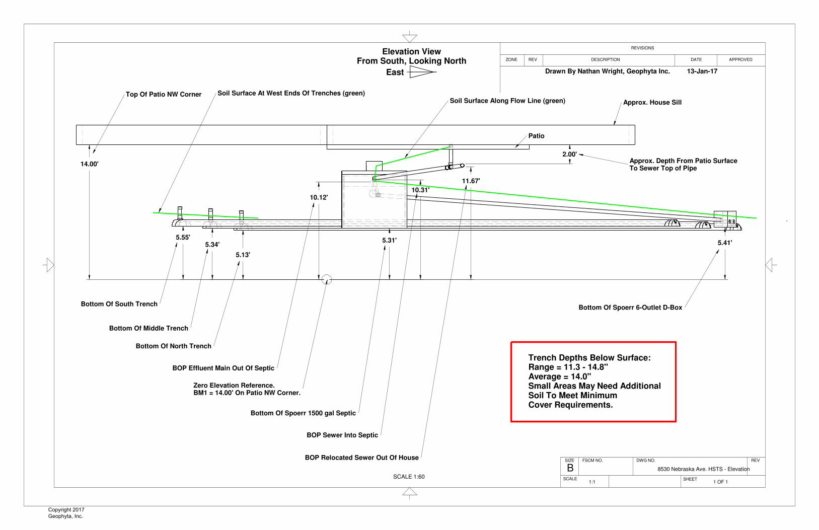
14.00'
11.67'
10.31'10.12'
5.41'5.55'
5.34'
5.13'
2.00'
5.31'
SCALE 1:60
Approx. House Sill
Approx. Depth From Patio SurfaceTo Sewer Top of Pipe
Bottom Of Spoerr 6-Outlet D-Box
BOP Relocated Sewer Out Of House
BOP Sewer Into Septic
Bottom Of Spoerr 1500 gal Septic
Zero Elevation Reference.BM1 = 14.00' On Patio NW Corner.
BOP Effluent Main Out Of Septic
Bottom Of North Trench
Bottom Of Middle Trench
Bottom Of South Trench
Top Of Patio NW Corner Soil Surface At West Ends Of Trenches (green)Soil Surface Along Flow Line (green)
Trench Depths Below Surface:Range = 11.3 - 14.8"Average = 14.0"Small Areas May Need AdditionalSoil To Meet MinimumCover Requirements.
Patio
REV
APPROVEDREV
SHEET
REVISIONS
DESCRIPTION
FSCM NO.
BSCALE
8530 Nebraska Ave. HSTS - Elevation
DATE
SIZE
ZONE
DWG NO.
1:1 1 OF 1
Drawn By Nathan Wright, Geophyta Inc. 13-Jan-17
Elevation ViewFrom South, Looking North
East y
Geoph
yta, In
c. ©
Copyright 2017 Geophyta, Inc.

Geoph
yta, In
c. ©
Copyright 2017 Geophyta, Inc.
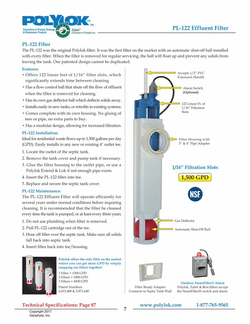
PL-122 FilterThe PL-122 was the original Polylok filter. It was the first filter on the market with an automatic shut-off ball installedwith every filter. When the filter is removed for regular servicing, the ball will float up and prevent any solids fromleaving the tank. Our patented design cannot be duplicated.
Features:� Offers 122 linear feet of 1/16” filter slots, which significantly extends time between cleaning.� Has a flow control ball that shuts off the flow of effluent when the filter is removed for cleaning.� Has its own gas deflector ball which deflects solids away.� Installs easily in new tanks, or retrofits in existing systems.� Comes complete with its own housing. No gluing of tees or pipe, no extra parts to buy.� Has a modular design, allowing for increased filtration.
PL-122 Installation:Ideal for residential waste flows up to 1,500 gallons per day(GPD). Easily installs in any new or existing 4" outlet tee.
1. Locate the outlet of the septic tank.2. Remove the tank cover and pump tank if necessary.3. Glue the filter housing to the outlet pipe, or use a Polylok Extend & Lok if not enough pipe exists. 4. Insert the PL-122 filter into tee.5. Replace and secure the septic tank cover.
PL-122 Maintenance:The PL-122 Effluent Filter will operate efficiently forseveral years under normal conditions before requiringcleaning. It is recommended that the filter be cleanedevery time the tank is pumped, or at least every three years.
1. Do not use plumbing when filter is removed.2. Pull PL-122 cartridge out of the tee.3. Hose off filter over the septic tank. Make sure all solids fall back into septic tank.4. Insert filter back into tee/housing.
www.polylok.com 1-877-765-9565Technical Specifications: Page 87
PL-122 Effluent Filter
7
Accepts 1/2” PVCExtension Handle
Alarm Switch(Optional)
122 Linear Ft. of1/16” FiltrationSlots
Filter Housing with3” & 4” Pipe Adapter
Gas Deflector
Automatic Shut-Off Ball
Filter Ready AdapterConnects to Septic Tank Wall
Outdoor SmartFilter® AlarmPolylok, Zabel & Best filters acceptthe SmartFilter® switch and alarm.
1,500 GPD
1/16” Filtration Slots
Polylok offers the only filter on the marketwhere you can get more GPD by simplysnapping our filters together!
1 Filter = 1500 GPD2 Filters = 3000 GPD3 Filters = 4500 GPD
Patent Numbers6,015,488 & 5,871,640
Geoph
yta, In
c. ©
Copyright 2017 Geophyta, Inc.

20.5"
20.0"
5.0"7.0"
nnnn4.5"
Concrete Lid
Add on risers in 6 inchincrements as needed.Min. Ht = 20.5"
20.0"
2.0"
DESCRIPTION
FSCM NO.
A
DATE
REVSIZE DWG NO.
APPROVEDZONE
Spoerr 6-Outlet D-Box
REVISIONS
SHEET
REV
SCALE 1:10
Drawn By Nathan Wright, Geophyta Inc. 13-Aug-13
Geoph
yta, In
c. ©
Copyright 2017 Geophyta, Inc.

8.0"
6.0"
24.0"3.3"
nnnn4.5"
nnnn4.0"
16.3"
O.D. DistributionManifold Pipe Entry
Trench Width,May Be 36" In Some Designs
Dome Height
Minimum Soil Cover.Silt Loam Or Better TextureWith Moderate Or StrongStructure When Soil Is AddedMore Than 2" Above Original Grade
Height Of Distribution Pipe Entry
Length Will Vary By Design
Trench Bottom Inpection Port
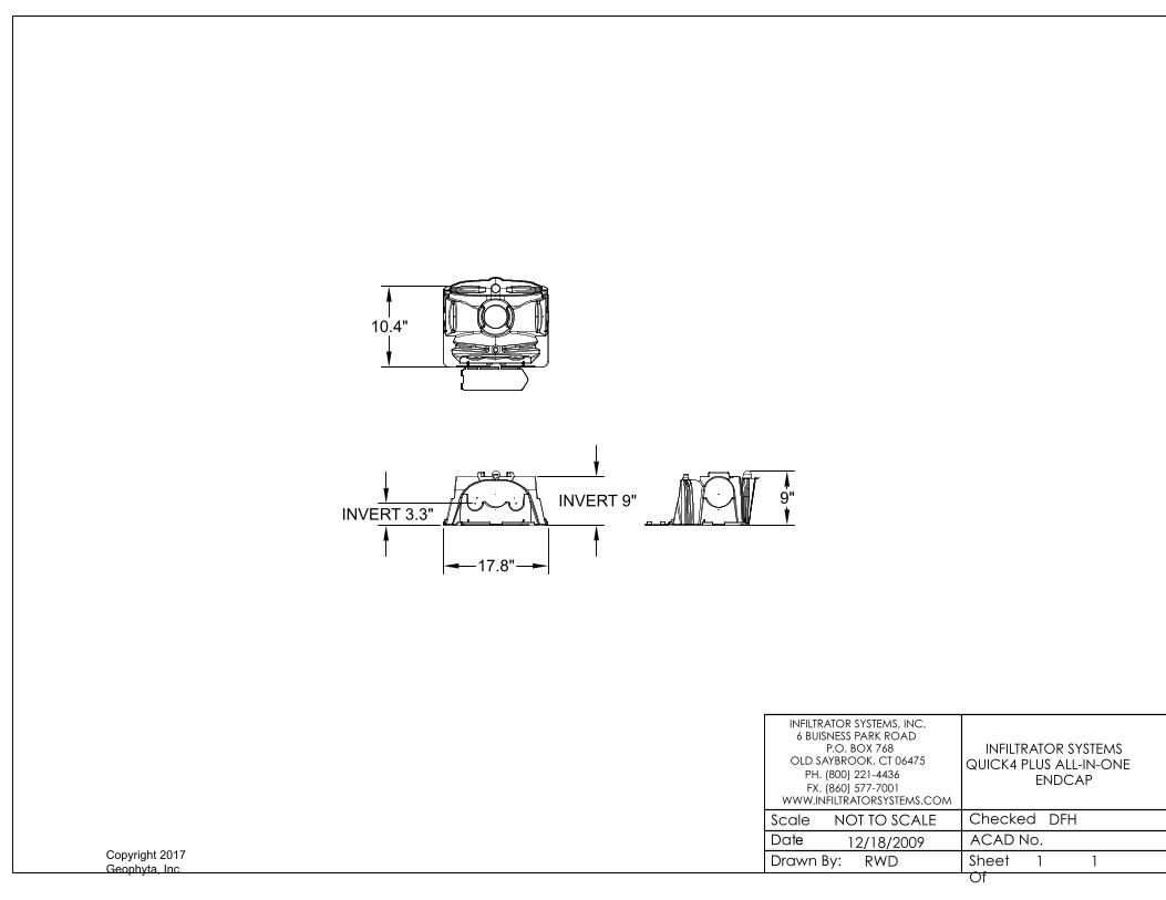
Infiltrator All-In-One Endcap
Infiltrator Standard Endcap
Soil Surface
DATE
REVISIONS
DWG NO.
SHEET
Standard Gravelless Leach Trench
ZONE
ASCALE
REV
REV
FSCM NO.SIZE
DESCRIPTION APPROVED
Drawn By Nathan Wright, Geophyta Inc. 4-Apr-15
DO NOT DIG TRENCHES IF SOIL WILL SMEAR
If Trench Sidewall & Bottom Smearing OccursDuring Excavation, Then Rake Sidewalls &Bottoms To Break This Smear Layer
1:15
Geoph
yta, In
c. ©
Copyright 2017 Geophyta, Inc.

1ACAD No.Checked
DateDrawn By:
Scale NOT TO SCALE
12/18/2009RWD
INFILTRATOR SYSTEMS, INC. 6 BUISNESS PARK ROAD
P.O. BOX 768OLD SAYBROOK, CT 06475
PH. (800) 221-4436FX. (860) 577-7001
WWW.INFILTRATORSYSTEMS.COM
Sheet Of
DFH
INFILTRATOR SYSTEMS QUICK4 PLUS ENDCAP
1
17.8"
4.5"
INVERT 3.3"
4.5"
8"
Geoph
yta, In
c. ©
Copyright 2017 Geophyta, Inc.

1ACAD No.Checked
DateDrawn By:
Scale NOT TO SCALE
12/18/2009RWD
INFILTRATOR SYSTEMS, INC. 6 BUISNESS PARK ROAD
P.O. BOX 768OLD SAYBROOK, CT 06475
PH. (800) 221-4436FX. (860) 577-7001
WWW.INFILTRATORSYSTEMS.COM
Sheet Of
DFH
INFILTRATOR SYSTEMS QUICK4 PLUS STANDARD LOW
PROFILE
1
52"
48"
34"
(EFFECTIVE LENGTH)
TOP VIEW
SIDE VIEW
FRONT VIEW
8"
Geoph
yta, In
c. ©
Copyright 2017 Geophyta, Inc.

4.0"
12.0"
4.3"
24.4"
17.8"
A Minimum Of TwoStainless Steel WoodScrews Required ToAttach PVC Pipe To Endcap
4" Sch40 PVC Pipe, Coupler, & Cap
Infiltrator All-In-One Endcap.See B.O.M. For Actual Part Number
A
REVISIONS
ZONE DESCRIPTION
SCALE
DATE APPROVED
DWG NO.
SHEET
FSCM NO.SIZE
REV
REV
Trench End Soil Inspection Port
1:10
Drawn By Nathan Wright, Geophyta Inc. 9-Oct-13
Geoph
yta, In
c. ©
Copyright 2017 Geophyta, Inc.
1ACAD No.Checked
DateDrawn By:
Scale NOT TO SCALE
12/18/2009RWD
INFILTRATOR SYSTEMS, INC. 6 BUISNESS PARK ROAD
P.O. BOX 768OLD SAYBROOK, CT 06475
PH. (800) 221-4436FX. (860) 577-7001
WWW.INFILTRATORSYSTEMS.COM
Sheet Of
DFH
INFILTRATOR SYSTEMS QUICK4 PLUS ALL-IN-ONE
ENDCAP
1
17.8"
INVERT 3.3"
10.4"
9"INVERT 9"
Geoph
yta, In
c. ©
Copyright 2017 Geophyta, Inc.

Quantity Part Name Section Comment
1 SCH40PVC4inchpipe2ft Sewer Main
1 SCH40PVC4inchpipe36in Sewer Main
1 SCH40PVC4inchpipe10ft Sewer Main
1 Sch40PVC4inchCap Sewer Main
1 SCH40PVC4inchpipe65.5ft Sewer Main
1 Sch40PVC4.0inchTwoWayCleanoutTeeSxSxS Sewer Main
6 Sch40PVC4.0inchCoupler Sewer Main
Misc. AdaptorsAsNeededForNewOutlet Sewer Main
Misc. PatioRepairAsNeeded Sewer Main
1 Spoerr1500galSepticW12inchRisers Septic Tank Spoerr 1500 gal
1 PolyLockPL122FilterHousingW11ext Septic Tank PolyLok or equiv.
1 SCH40PVC4inchpipe40ft Effluent Main
7 Sch40PVC4.0inchCoupler Effluent Main
1 SCH40PVC4inchpipe53.5ft Effluent Main
1 Sch40PVC4.0inch45Ell Effluent Main
1 DistributionBox6outlet Distribution Manifold Spoerr 6-outlet
Misc. SD35PVC4inchPipe Distribution Manifold
Misc. SD35PVC4inchFittings Distribution Manifold
1 SD35PVC4inch90EllTrenchRestingElbow Distribution Manifold
3 InfiltratorQ4PlusEQ36LPEndCap Leach Trenches
3 DomeStraightTrench3ftWx4ftLx8inH15SectQ4PlusEQ36LP60ftTotal Leach Trenches
3 Sch40PVC4inchCap Trench Soil Inspection Port
3 SCH40PVC4inchpipe1ft Trench Soil Inspection Port
3 SCH40PVC4inchpipe4.0in Trench Soil Inspection Port
3 InfiltratorQ4PlusAllInOneEndCap Trench Soil Inspection Port
3 Sch40PVC4.0inchCoupler Trench Soil Inspection Port
6 StainlessSteelWoodScrew Trench Soil Inspection Port
1 Pump, Crush, & Backfill Old Septic Tank, Replace Patio
1 Fill Soil If Needed
1 Grass Seed And Fertilizer As Needed
1 CALL BEFORE YOU DIG To Locate Utlities
Bill Of Materials - 8530 Nebraska Ave. HSTS - Gravelless Leach Trench System
Installer substitution of materials not specfied in this Bill Of Materials may void
Health Dept. approval of this design and will result in a re-design fee and is the
sole responsibility of the installer.
Design Prints Take Precedence Over This Bill of Materials. This is a best
estimate of materials required and is provided as a convenience to
installers. This BOM is not required for design approval.
Geoph
yta, In
c. ©
Copyright 2017 Geophyta, Inc.

Copyright, 2011 Geophyta, Inc. Page 1 of 4
Operation and Maintenance Procedures
Home Septic Treatment Systems With
Effluent Distribution Through In-Soil Leach Trenches
Home septic treatment systems are biologically based systems. They rely on both anaerobic and aerobic
microorganisms to process human waste. These systems may utilize processing, storage, and pumping
tanks. A soil absorption component, the leachfield, also processes, treats, and disperses septic effluent.
Any abuse of this biological treatment system will result in less efficient sewage treatment and early
failure of your new system.
Improper operation and/or maintenance of your home septic treatment system
will result in its failure.
Geophyta, Inc. strongly recommends that a homeowner hire a professional
service provider to inspect and maintain your system. Your county health
department has a list of registered service providers. Make sure that your
service provider has septic tank and leachfield maintenance experience.
1) Homeowner Responsibility:
a) The system owner is responsible for the continuous operation and maintenance of this home
septic treatment system
b) Your county health department may require third-party inspection and maintenance of your
home septic treatment system.
c) Home Interior Design & Appliance Selection:
i) Install water conserving fixtures such as low flow shower heads, low flow toilets, and front
loading washers.
ii) Space out water use throughout the day and week. Avoid doing all laundry in one day.
iii) Repair all water leaking fixtures.
iv) Eliminate garbage disposals, or limit their use. Collect food scraps with sink strainers for
disposal as trash or for composting; this includes coffee grounds.
v) DO NOT pipe sump pump output into your sewer line.
d) Home Landscaping Limitations:
i) Do not pipe roof downspouts or any other rainwater drainage into the septic or dose tanks.
ii) Divert all downspouts or other rainwater drainage away from your entire septic system.
iii) Divert all downspouts or other rainwater drainage away from the leachfield area.
iv) Do not drive or park cars, boats, heavy equipment, or other vehicles on or near septic
system tanks and leachfield areas.
Geoph
yta, In
c. ©
Copyright 2017 Geophyta, Inc.

Copyright, 2011 Geophyta, Inc. Page 2 of 4
v) Do not add additional soil fill on or near the leachfield. This will limit air movement into the
soil needed for effluent treatment and may cause system failure.
vi) Limit lawnmower traffic on the leachfield when soil is excessively wet.
vii) Do not plant any deep rooted plants on top of or near your leachfield soil absorption area.
e) Home Resident Responsibilities:
i) Only flush or drain bio-degradable human waste, toilet paper, laundry and dish and personal
care soaps, and water into your home septic treatment system.
ii) Severely limit disposal of food fats, oils, and greases. These will clog your system.
iii) Do not flush or drain undiluted bleach, cleansers, or drain cleaners.
iv) Do not flush any non-biodegradable items. For example, plastic items.
v) Do not flush or drain motor oils, greases, anti-freezes, cleaners, etc.
vi) Do not flush cat litter.
vii) Do not flush paper towels, facial tissue, cigarette butts, disposable diapers, sanitary napkins,
tampons, or condoms.
viii) Do not flush prescription or over-the-counter drugs. Antibiotics and cancer treatment drugs
are very harmful to your home septic treatment system.
ix) Do not dump solvents like dry cleaning fluid, pesticides, photographic chemicals, paint
thinner down the drain.
x) Don't use septic tank additives, unless health department approved.
xi) Don't drain a hot tub or large amounts of water into your septic system.
f) Home Improvement/Expansion:
i) Contact your county sanitarian before adding new driveways, decks, patios, pools, and
outbuildings not identified on your original layout plan to make sure all setback distances
from your septic system tanks and mound are met.
ii) Contact your county sanitarian before adding bedrooms and/or increasing your home
occupancy. This may overload your septic system. Septic system expansion may be
required to prevent failure.
g) Homeowner Cautions:
i) DO NOT ENTER TANKS WITHOUT PROPER SAFETY EQUIPMENT. Septic and dose tanks
contain noxious and deadly gases.
ii) Pump or dose tanks and control boxes contain electrical components. ELECTRICAL SHOCK
HAZARD CAN EXIST WITH IMPROPERLY WIRED OR FAILING COMPONENTS.
iii) Always keep tank fall guards in place, except for the time needed to replace components
when safety equipment is present.
iv) Always replace and secure septic and dose tank lids after completing any inspection.
v) Any disconnection or removal of filters, screens, floats, alarms, and/or control panels will
result in system failure.
vi) Contact your county sanitarian for allowed homeowner maintenance and repair of your
septic system.
Geoph
yta, In
c. ©
Copyright 2017 Geophyta, Inc.
Copyright, 2011 Geophyta, Inc. Page 3 of 4
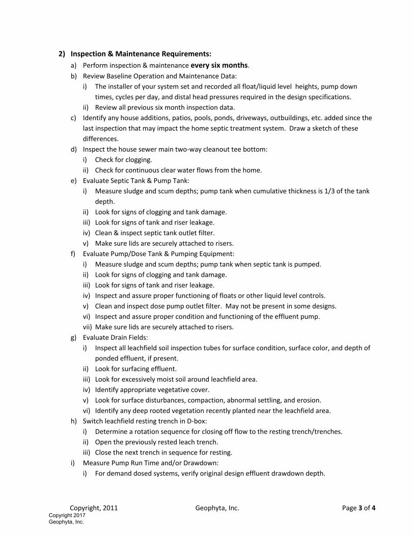
2) Inspection & Maintenance Requirements:
a) Perform inspection & maintenance every six months.
b) Review Baseline Operation and Maintenance Data:
i) The installer of your system set and recorded all float/liquid level heights, pump down
times, cycles per day, and distal head pressures required in the design specifications.
ii) Review all previous six month inspection data.
c) Identify any house additions, patios, pools, ponds, driveways, outbuildings, etc. added since the
last inspection that may impact the home septic treatment system. Draw a sketch of these
differences.
d) Inspect the house sewer main two-way cleanout tee bottom:
i) Check for clogging.
ii) Check for continuous clear water flows from the home.
e) Evaluate Septic Tank & Pump Tank:
i) Measure sludge and scum depths; pump tank when cumulative thickness is 1/3 of the tank
depth.
ii) Look for signs of clogging and tank damage.
iii) Look for signs of tank and riser leakage.
iv) Clean & inspect septic tank outlet filter.
v) Make sure lids are securely attached to risers.
f) Evaluate Pump/Dose Tank & Pumping Equipment:
i) Measure sludge and scum depths; pump tank when septic tank is pumped.
ii) Look for signs of clogging and tank damage.
iii) Look for signs of tank and riser leakage.
iv) Inspect and assure proper functioning of floats or other liquid level controls.
v) Clean and inspect dose pump outlet filter. May not be present in some designs.
vi) Inspect and assure proper condition and functioning of the effluent pump.
vii) Make sure lids are securely attached to risers.
g) Evaluate Drain Fields:
i) Inspect all leachfield soil inspection tubes for surface condition, surface color, and depth of
ponded effluent, if present.
ii) Look for surfacing effluent.
iii) Look for excessively moist soil around leachfield area.
iv) Identify appropriate vegetative cover.
v) Look for surface disturbances, compaction, abnormal settling, and erosion.
vi) Identify any deep rooted vegetation recently planted near the leachfield area.
h) Switch leachfield resting trench in D-box:
i) Determine a rotation sequence for closing off flow to the resting trench/trenches.
ii) Open the previously rested leach trench.
iii) Close the next trench in sequence for resting.
i) Measure Pump Run Time and/or Drawdown:
i) For demand dosed systems, verify original design effluent drawdown depth.
Geoph
yta, In
c. ©
Copyright 2017 Geophyta, Inc.
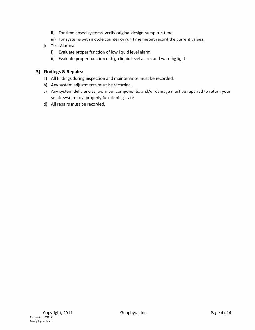
Copyright, 2011 Geophyta, Inc. Page 4 of 4
ii) For time dosed systems, verify original design pump run time.
iii) For systems with a cycle counter or run time meter, record the current values.
j) Test Alarms:
i) Evaluate proper function of low liquid level alarm.
ii) Evaluate proper function of high liquid level alarm and warning light.
3) Findings & Repairs:
a) All findings during inspection and maintenance must be recorded.
b) Any system adjustments must be recorded.
c) Any system deficiencies, worn out components, and/or damage must be repaired to return your
septic system to a properly functioning state.
d) All repairs must be recorded.
Geoph
yta, In
c. ©
Copyright 2017 Geophyta, Inc.