honda - justanswerww2.justanswer.com/uploads/mr/mr2cycle/2014-10-11_031539...2014/10/11 · honda...
TRANSCRIPT

HONDA HS626
PREFACE This manual covers the construction, function and servtcmc procedures of the Honda H$828 snowblower. ~ Careful observance of these instructions will result in better. safer service work.
NIO;W!hll£i Indicates a strong possibility of severe personal injury or death if instructions are not followed.
CAUTION: Indicates a possibility of personal injury or equipment damage if instructions are not followed.
NOTE: Gives helpful information.
CAUTION: Detailed descriptions of standard workshop procedures. safety principles and service operations are not included. Please note that this manual does contain warnings and cautions against some specific service methods which could cause PERSONAL INJURY to service personnel or could damage the product or make it unsafe. Please understand that these warnings cannot cover all conceivable ways in which service, whether or not recommended by American Honda, might be done. or of the possible hazardous consequences of each conceivable way, norcoutd American Honda investigate all such ways. Anyone using service procedures or tools. whether or not recommended by American Honda. must SBtisfy himself thoroughly that neither personal safety nor product safety will be jeopardized by the service methods or tools selected.
All information contained in this manual is based on the latest product information available at the time of printing. We reserve the right to make changes at any time without notice. No part of this publication may be reproduced, stored in a retrieval system. or transmitted, in any form by any means, electronic, mechanical, photocopying, recoding, or otherwise, without the prior written permission of the publisher. This includes text. figures and tables.
HONDA MOTOR CO., LTD SERVICE PUBLICATIONS OFFICE
HS928
CONTENTS
SPECIFICATIONS .. SERVICE INFORMATION
MAINTENANCE
ENGINE REMOVAL/INSTALLATION
FUEL SYSTEM
RECOIL STARTER/FAN COVER/MUFFLER
FLYWHEEL/IGNITION COIL
CYLINDER HEAD/VALVES
CYLINDER/CRANKCASE
PISTON/CRANKSHAFT /CAMSHAFT
I CHUTE Ill I AUGER/AUGER TRANSMISSION lfJ 1
TENSION PULLEY I AUGER BRAKE 1 s• I HYDROSTATIC TRANSMISSION IGI I TRACKS IIOJ I SHIFT LEVER/CHUTE LEVER/CONTROL PANEL lt::l I CLUTCH LEVER/HANDLE I fl I AC STARTER MOTOR 11:1 I OPERATION ll!l
INDEX

HONDA HS724 · HS928
1. SPECIFICATIONS
1. SPECIFICATIONS •HS928 DIMENSIONS AND WEIGHTS
Model
Description code
Type
Overall length mm lin)
Overall width mm(inl
Overall height mm(in)
Handle height mm(inl c-=---··
Dry weight kg llbs)
Curb weight kg (lbsl
ENGINE
Model
Engine model
Type
Displacement
Bore x Stroke
Compression ratio
Cooling system
Ignition system
Ignition timing -Spark plug
Carburetor
Air cleaner
Governor
Lubrication system
Oil capacity
Starting system
--- ---Stopping system
HS928
1. SPECIFICATIONS 2. WIRING DIAGRAMS
HS928
SZAS
TA I TAS I WA I WAS
1,422 (56.0) I 1,400 155.1) I 1,452 (57.2)
725 (28.5)
1,022 (40.2) I 1,042 (41.0)
910 (35.8)
105 (231) I 109 (240) I 96 (212) I 99 (218)
111 (245) I 116(256) I 102 (225) I 105 (231)
HS928
GX270K1
4-stroke, overhead valve, single cylinder inclined by 25' ·---
270 cm 3 (14.8 cu in)
77 x 58 mm (3.0 x 2.3 in)
8.2: 1
Forced-air cooling
Transistorized magneto ignition --
20' B.T.D.C.
BPR5ES (NGK), W16EPR-U (DENSOI
Horizontal, butterfly valve type
No filter
Mechanical centrifugal governor
Forced splash type
1.1£ (1.2 US qt, 1.0 Imp qt)
TA and WA types: Recoil starter TAS and WAS types: Recoil starter and AC electrical starter
Primary circuit ground

FRAME
Model
Type
-Clearing width
Clearing height
Clearing capacity --·
Discharge distance
Continuous operating time
~e1 tank capacity
Snow-clearing mechanism
Snow throwing Right and left direction, angle Up and down
Auger Shape
Outside diameter
Set speed ~-
Auger height Number of positions adjustment Method
Blower Number of blades -.--------
Outside diameter
j Set speed ----------- .
Chute and chute guide control
PTO shaft to transmission
Main clutch Type
Operation
~ain transmission Type
Number of speeds
Transmission oil
Oil capacity
Sub transmission Type
Reduction ratio
Lubricant
:Orive method Type
Size
Traction speed Forward
Reverse
PTO shaft to blower
August clutch Type
Operation - --- -·-
Auger Type transmission
---Reduction ratio
Transmission oil
Oil capacity
r-
HS928
HONDA HS724 • HS928
HS928
TA I TAS WA I WAS
710 mm (28 in)
510 mm (20 in)
50 t/hr
15m 149.2 ft)
2.5 hours
5.3 £ (1.4 US gal)
2-stage
210°
70°
Spiral ... ~ 355 mm (14.0 in)
125 rpm
3-stage I --
Foot pedal ~- --3
300 mm 111.8 inl
1,370 rpm
Hand operated remote control
V-belt (SA291
Belt tension
Clutch lever
Hydrostatic transmission (HST)
Variable speed
Honda Hydrostatic transmission fluid
0.75£ (0.79 US qt, 0.66 Imp qt)
Constant meash
6.38: 1 6.00: 1 ----· Grease
Rubber track Wheel
120 X 60 X 21 14x40-6
0- 2.8 ft/sec (0- 0.85 m/sec) 0- 3.6 ft/sec (0- 1.10 m/sec)
0- 2.1 ft/sec (0- 0.64 m/secl 0 - 2.2 ft/sec (0- 0.66 m/sec) V-belt ILB35)
---
Belt tension ------··
Clutch lever -----
Worm gear
11 : 1
SAE #90 gear oil
0.16 f (0.169 US qt, 0.1411mp qt)


HONDA. HS724 · HS928
2. WIRING DIAGRAMS • H$724 TA and WA types o HS92B TA and WA types
ENGINE SWITCH
q fiJ ·-,
ENGINE ·1'~; GROUND
SPARK Pi UG
ENGINfo BLOCK
o HS928 TAS and WAS types
SWITCH ROX
STARTER SWITCH
"' I I • 1
1
<.:OIL
"";~ ;:.,::, ·+D
' -·
STAR1ER MOtoR
ii\ 0
loNGINE BLOCK
0 E
"''
ENGINE 1·. GROUND -
HS928
I • I
LIGHTING COIL
ENGINE SWITCH
P. "' ' I
J
ill
'
I • !
I ;__,·
:·'' ''12
I COIL
1 SPARK PLUG
\i
LIGHTING COIL
-----··-- -------
tl',mat• n. Btowo~ v , ¥~•k>"' 0 '0•~"1)~ 1\": ~u~ l.,'· \ og~1 1•'v• () ; \';r~!"' I~ I '0~1 ~·oo~
A j IW~ f> l'•n>
w •. 'f'!.n._w __ J.?: ---~---
"' l'llil•'~ . '! ~~-~ ~.~:~ •... • Yoii<JW
'" "'"" "' ''Q"' l>'u~
" I"'""" " l1~l1l ~·~a"
' ~-! n-~ ' p,,.
w·w"''"

•
SERVICE INFORMATIONS 1. GENERAL SAFETY 2. SERVICE RULES
HS928
6. SPECIAL TOOLS 7. TROUBLESHOOTING
HONDA Hsses
3. SERIAL NUMBER LOCATION 8. LUBRICATION POINTS 4. MAINTENANCE STANDARDS 9. CABLE/HARNESS ROUTING 5. TORQUE VALUES
GENERAL SAFETY ~Y attention to these symbols and their meanings: -· I Nh'dt'i@U Indicates a strong possibility of severe personal injury or death if instructions are not followed. LCAUTION: Indicates a possibility of personal injury or equipment damage if instructions are not followed.
• Stop the engine, and remove the spark plug cap before servicing the snowblower. • If the motor must be running to do some work, make sure the area is well ventilated. Never run the engine in a closed
area; the exhaust containes poisonous carbon monoxide gas. • Gasoline is extremely flammable and is explosive under certain conditions. Do not smoke or allow flames or sparks in
your working area.
CAUTION:
) ~eep BW'!_Y fr~-~ rotating or hot parts and high V'!_ltage wires when the engine is running.
SERVICE RULES 1. Use genuine Honda or Honda-recommended parts and lubricants or their equivalents. Parts that do not meet Honda's design
specifications may damage the unit. 2 Use the special tools designed for the product. 3. Install new gaskets, 0-rings, etc. when reassembling. 4 When torquing bolts or nuts, begin with larger-diameter or inner bolts first and tighten to the specified torque diagona,lly,
unless a panicular sequence is specified. 5 Clean parts in cleaning solvent upon disassembly. Lubricate any sliding surfaces before reassembly. 6. After reassembly, check all parts for proper installation and operation. 7. Many screws used in this machine are self-tapping. Be aware that cross-threading or overtightening these screws will strip
the female threads and ruin the hole. 8. Use only metric toots when servicing this unit. Metric bolt, nuts and screws are not interchangeable with nonmetric
fasteners. The use of incorrect tools and fasteners will damage the unit. 9. Follow the instructions represented by these symbols when they are used:
[ _P ____ ] · Indicates the reference page.
0 x 0 ( ) · Indicates the diameter, length, and number of the flange bolt used.
Apply grease Is ~OLJ Use special tool Apply oil
(Low temperature)
CAUTION: ~~rease ,
[ -u;~ -;;;-~tor ~ii may-caus;·ski~ ca~cer if repe~-iedl.(.left i~ coniact with the skin for prolonged periods. Although this is unlikely unless you handle used oil on a daily basis, it is still advisable to thoroughly wash your hands with soap and water as soon as possible after handling used oil.
·-----
NOTE
• Dispose of used motor oil in a manner that is compatible with the environmen·t. We suggest that you take i~ in sealed container to your local waste disposal site, or service station for reclamation.
• Do not throw it in the dustbin or pour it on to the ground, down sewers or drains. • Draining ?an be performed rapidly and completely while the engine is still warm.

HONDA HSB&!B
SERIAl NUMBER lOCATION
HS928
Serial numbers of the engine and frame are stamped on the engine crankcase and frame as illustrations shown. Always specify these numbers when inquiring about the snowblower or ordering parts in order to get correct parts for the unit being serviced.
ENGINE NUMBER
FRAME NUMBER

HS928
2. SERVICE INFORMATION HONDA HS724 • HS928
I_ -~~ M;~N~E~ANCE STAND. ARDS I. 2. TORQUE VALUES ~ ~ - - ---- -- - ~-··.
------- -~ 3. SPECIAL TOOLS 4. CABLE/HARNESS ROUTING
--------·-···--- ,_,_ -·---- __ , ___________ _
1. MAINTENANCE STANDARDS •ENGINE HS928
Part
Engine
Cylinder
Cylinder head
Piston
Item J M8~imum speed-r Idle speed ' Cylinder compression I
j Sleeve 1: D.
' Warpage
Skit 0. D. Piston-to-cylinder clearance Piston pin bore I. D.
Standard
3,600 ± 150 rpm 2,100 ± 1 50 rpm
588- 834 kPa (6.0- 8.5 kgf/cm 1,
85.3 120.9 psrl at 600 rpm r·-f- 77.00 mm (3.031 in)
~t- 76.985 m~(3.0309 in)
Service Hrnit
76.85 mm 13.026 in) 0.12 mm (0.005 in)
18.042 mm (0.7103 in) - ---- -------~ ·-····-~---ro 015-0.052 mm 10.0006-0.0020 in)
18.002 mm (0.7087 in)
Piston pin
Piston rings
Connecting rod
Crankshaft
Valves
Piston pin 0. D. 18.00 mm 10.709 in) Piston-to-piston pin clearance _ 02 -~ 0.01~_mm (~-~0.?01- 0_.0006 in)
Side clearance Top/Second 1 0.015-0.045 mm 10.0006- 0.0018 in) End gap Top/Second ~ 0.2-0.4 mm (0.01- 0.02 in)
Oil 0.2- 0.7 mm 10.01-0.03 in) Ring width Top/Second 2.0 mm (0.08 in)
----- '' "--·---- ··-- """ -----------sriiall end 1. D. 18.005 mm 10.7089 in) Big end I. D. 33.025 mm (1.3002 in) Big end oil clearance 0.040- 0.066 mm 10.0016- 0.026 in) Big end side clearance 0.1 - 0.7 mm (0.004- 0.028 in)
-- ·-Crank pin 0. 32.985 mm (1.2986 in)
1 Valve clearance IN
EX IN
EX
0.15 ± 0.02 mm 0.20 i 0.02 mm
6.59 mm (0.259 in) 6.55 mm 10.258 in)
I 1 Stem 0. D.
- --- --l Valve guides Guide I. D. IN/EX
IN 6.60 mm 10.260 in) I
Stem~to·guide
lclearance
_val~e sprin~-~- ~p-~i~-~ free len~~h
0.010-0.037 mm 10.0004-0.0015 in) EX 0.050-0.077 mm 10.0020- 0.0030 in)
IN/EX ____ ~()_mm (1:54 in)
1.1 mm 10.04 in)
17.95 mm (0.707 in) 0.08 mm (0.003 in)
- -----0.15 mm (0.006 in)
1.0 mm (0.04 in) 1.0 mm (0.04 in)
1.75 mm (0.069 in) -----· -- ----. 18.07 mm (0.711 in) 33.07 mm (1.302 in) 0.12 mm 10.005 in)
1.0 mm (0.04 in)
32.92 mm 11.296 in)
6.44 mm (0.254 in) 6.40 mm (0.252 in)
6.66 mm 10.262 in) 0.10 mm (0.004 in) 0.12 mm 10.005 in)
Cylinder head Seat width
Camshaft Cam height
37.5 mm (1.48 in)
2.0 mm 10.08 in) ---j~---
IN 31.52-31.92 mm (1.241-1.257 in) 31.35 mm (1.234 in) EX 31.51-31.96 mm 11.243- 1.258 in) 31.35 mm (1.234 in)
Camshaft O.D.
Crankcase cover Camshaft holder 1.0.
Carburetor Main jet Float level Pilot screw opening
-~--·-r --------- ---" -Spark plug Gap
Ignition coil
Plug cap resistance ----- ---- ----
Primary coil resistance Secondary coil resistance Air gap (at flywheel)
15.984 mm 10.6293 in) 15.92 mm (0.627 in)
16.0 mm (0.63 in) --------------- ~-----
#92 13.2 mm 10.52 in)
2 rurns out
0.7-0.8 mm (0.028- 0.031 in) 7.5-12.5 kn
.. -- -------- ---·-- -0.8- 1.0 il 5.9-7.1 kll
0.4 .l 0.2 mm (0.016 .t 0.008 in)
------· --

HONDA HS724 • HS928
2. TORQUE VALUES • ENGINE
Item
Cylinder head bolt IHS928)
IHS7241
Rocker arm pivot lock nut
Rocker arm pivot bolt
Crankcase cover bolt
Connecting rod bolt (HS928)
(H$7241
Muffler mounting nut
Air cleaner mounting nut (HS928)
iHS7241
Air cleaner wing nut -- ---
Oil drain bolt IHS928)
iHS724)
Oil drain extension (HS928)
Fuel tank mounting bolt, nut IHS9281
IHS7241
Fuel sediment cup (H$724)
Fuel filter joint nut
HS92B
Thread dia. x pitch Tightening torque
M10x 1.25 ----------
M8 X 1.25
M6 X 0.5
M8 x 1.25 (special bolt) ---- -------·-M8 X 1.25
M8 x 1.25 (special bolt)
M7 X 1.0
N•m 34
24 10
24
24
14
Max 1.25 '---'-----+--"
M6 X 1.0
M6 X 1.0 --------
M6 X 1.0
M10 x 1.25 (special bolt) - --
10
9
23
M10x 1.25 18 ,_ --,--M-12 ;-,-=.2-::-5----+---::23
~-~k\l_f•m 3.5
2.4
1.0
2.4
2.4
1.4
1.2
2.4 ~---------
0.9
1.0
0.9
2.3
1.8
2.3
M8 X 1.25 --+
24 2.4
M6 X 1.0
M24 X 1.0 -----···-:-c:--c-
M10 x 1.25 (special nut)
10
4
2
1.0
0.4
0.2
lbfoft
25
10
9 -
17 -----
6.5
7
6.5
17
13
17
17 - --------- ·--
7
2.9
1.4 -~,~ ~' ~'-' ---- ,,~------
Flywheel nut IHS9281
IHS724)
• HYDROSTATIC TRANSMISSION
Item -------· --
Auger transmission drain bolt
Port plug bolt
Check valve bolt
Pump case bolt
Transmission case bolt
Drain plug bolt
Neutral valve arm bolt
Oil seal holder bolt
Trochoid housing bolt
Bearing holder bolt
M16 x 1.5 (special nut) I---
M14 x 1.5 (special nut)
113
74
83
54
Tighten in_~ torque ___ , Thread dia. x pitch
____ --~-:--:-c---)-~ _l<gf•m lbf.ft M8 x 1.25 (special bolt) 18 1.8 13
M10x 1.25 -+-~- ~-·
M10x 1.25 -- -· ------------
M8 X 1.25
MB X 1.25
M14 X 1.25
M6 X 1.0
M6 X 1.0
M6 X 1.0
M6 X 1.0
___ ,_, _____ 19
19
20
20
39
10
10 --- -··-- -------
10
10
-------
~
1.9 14
1.9 14 ---- ------
2.0 -- ---2.0
·-----4.0
~----
1.0
1.0
1.0
1.0
--
14 ,, ___ -
14 ----~-
29
7
7
7
7
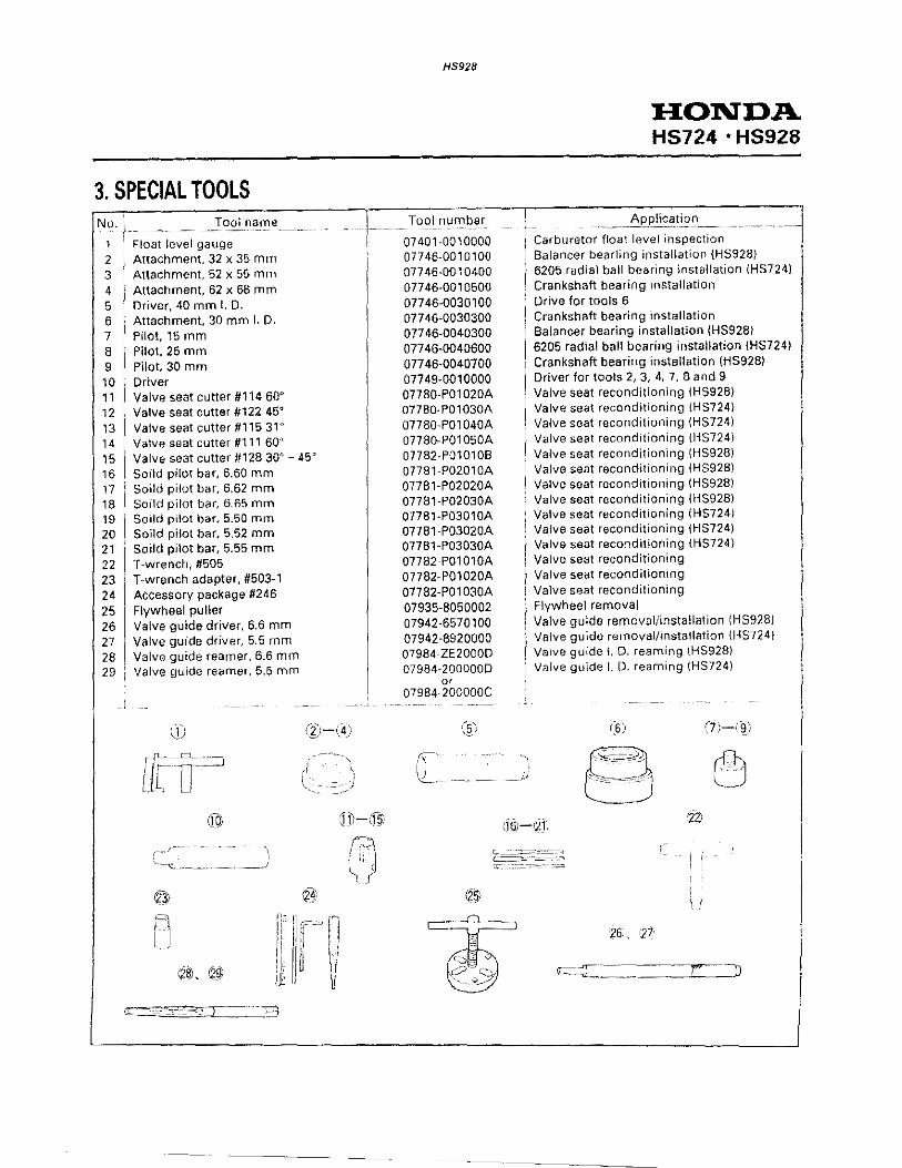
3. SPECIAL TOOLS No.
1 2 3 4
5 6 7 8 9 10 11 12 13 14 15 16 17 18 19 20 21 22 23 24 25 26 27 28 29
Tool name
Float level gauge Attachment 32 x 35 mm Attachment 52 x 55 mm Attachment, 62 x 68 mm Driver, 40 mm I. D. Attachment, 30 mm I. D. Pilot, 15 mm Pilot, 25 mm Pilot, 30 mm Driver Valve seat cutter #114 60" Valve seat cutter #122 45" Valve seat cutter #1 15 3P Valve seat cutter #111 60'' Valve seat cutter #128 30'·- 45' Soild pilot bar, 6.60 mm Soild pilot bar, 6.62 mm Soild pilot bar, 6.65 mm Soild pilot bar, 5.50 mm Soild pilot bar, 5.52 mm Soild pilot bar, 5.55 mm T-wrench, #505 T-wrench adapter, #503-1 Accessory package #246 Flywheel puller Valve guide driver, 6.6 mm Valve guide driver, 5.5 mm Valve guide reamer, 6.6 mm Valve guide reamer, 5.5 mm
\ ' _,
HS928
Tool number
07401-0010000 07746-0010100 077 46-001 0400 07746-0010500 07746-0030100 077 46-0030300 077 46-0040300 07746-0040600 077 46-00407 00 07749-0010000 07780-P01020A 07780-P01030A 07780-P01040A 07780-P01050A 07782-P01010B 07781-P02010A 07781-P02020A 07781-P02030A 07781-P03010A 07781-P03020A 07781-P03030A 07782-P01010A 07782-P01020A 07782-P01030A 07935-8050002 07942-6570100 07942-8920000 07984·ZE2000D 07984-2000000
or 07984 200000C
(§_)
-- ;.1
HONDA HS724 • HS928
--~plic~!i9_~_ Carburetor float level inspection Balancer bearling installation {HS928) 6205 radial ball bearing installation IHS7241 Crankshaft bearing installation Drive for tools 6 Crankshaft bearing installation Balancer bearing installation IHS9281 6205 radial ball bearing installation IHS7241 Crankshaft bearing installation iHS92BI Driver for tools 2, 3, 4, 7, 8 and 9 Valve seal reconditioning (HS92BI Valve seat reconditioning (HS724) Valve seat reconditioning {HS724) Valve seat reconditioning {HS724) Valve seat reconditioning (HS928) Valve seat reconditioning \HS928) Valve seat reconditioning {HS928) Valve seat reconditioning iHS928) Valve seat reconditioning { H$724) Valve seat reconditioning (HS724) Valve seat reconditioning (HS724) Valve seat reconditioning Valve seat reconditioning Valve seat reconditioning Flywheel removal Valve guide removal/installation IHS9281 Valve guide removal/installation iHS724) Valve guide L 0. reaming (HS928) Valve guide I. D. reaming iHS724l
(6) (7 __ ;-(~)
: I
__ ..J__)J

H$928
TROUBLESHOOTING e ENGINE a. GENERAL SYMPTOMS AND POSSIBLE CAUSES
Hard starting
Engine lacks power
Readjust P. 3-5 Disassemble and inspect P. 5-3
IGNITION COIL air gap misadjusted
- Readjust P. 7-2
Readjust P. 3-9
inspect and correct P. 8-3
CYLINDER, PISTON or PISTON
RING worn Disassemble and inspect P. 10-1 and 10-2
HONDA HSS2B
Engine will not rev sufficiently
Poor performance at high speed
Poor perlormance at low speed

HS928
HONDA HSB2S
b. HARD STARTING
<MECHANICAL CAUSES>
[I .!:1~) ~C~h~ec~k~f~u~e~l ~le~v~e~l.======}--1----- No fuel ------1:::!•~F~i~ll~w~i~th~fu~e~l~a~n~d~s~ta~r~t~a~g~ai~n~. =]
L Suff1c1ent fuel 1n tank
2) Adjust the throttle cable that is linked choke (P. 3-9).
3) Remove spark plug and check. Dry --------~----------------~ • Check for blockage of filter and dis
connect or damaged of fuel tube. • Check for blockage of port and noz
zle of carburetor.
'----- Wet ------~r..-;-;:CI;::e:a:n-.:e-;:le:::c:::tr:::o::;d:es;::an:::d:;-:re:::s:::ta::,:::,,:::,.~k:;i:Jng care that choke is not closed toe much.
4) Install the spark plug cap and try spark test ·{P. 2-1 0)
• CYLINDER COMPRESSION TEST
1) Remove the spark plug cap and the spark plug.
Good spark
I Go to P. 2-9
l
2) Install a compression gauge in the spark plug hole. 3) Crank the engine several times with the recoil starter and
measure the compression.
COMPRESSION 6.0-85kg/cm' (85-121 psi) at 600 min-1 (rpm)
• If flooding is severe, check carburetor float valve.
COMPRESSION GAUGE (COMMERCIALLY
AVAILABLE)

5) Install the compression gauge in the spark plug hole and crank the engine several times.
6) Install the spark plug and restart the engine.
d. AC STARTER MOTOR
<ELECTRICAL CAUSE>
HS928
I From P. 2-18.
L Abnormal co
Normal camp
mpression -------1
ression
HONDA HSB2B
e Check for incorrect valve clearance.
e Check for loose cylinder head bolts.
• Check for heavy carbon deposits in combustion chamber.
• Check for defective cylinder head gasket, valves or valve seats.
e Check for worn piston rings, piston or cylinder.
r STARTER MOTOR does not operate J
l I
Check that electricity is available at the
of the power cord.
end ]~ ___ N_O_E~L_E_C_T_R_IC_IT_Y ____ ---1 I
• Turn receptacle switch ON. e Plug cord into a functioning receptacle. • Replace power cord.
1 OK
~~~------~~~~~--------1-----~N~O~G~O~O~D~----~f r Replace starter switch. Check starter switch (P. 1 8-3) f
r Check diode connections. I _____ _cN~O:__G~O=O':"D _____ I c . l L__o~n_n_e_c_t_o_r_r_e~p_a_"_· _________ _
j OK
r Check diode IP. 18-4) NO GOOD Replace diode.
r Check starter motor (P. 18-4 and 1 8-5) 1-----N~O::o._:G~O=O:.:D:__ ___ r Replace starter motor.

HS928
HONDA. HSB2B
c. IGNITION SYSTEM TROUBLESHOOTING
I 1) Engine does not start. I
I 2) Perform the spark plug test. I
133~) (c)h;;e;;c;kk-a;g~a;;iiinn~w;;ittth;-;;a-n;;e;w;;~sp~a;-;r*k-l-j----,---- Sparks ------------[1 ~·~~R~ep~l~a~c~e~t~h~e~s~p~a~r~k ~p~l u~g~.Jj plug.
'-----No sparks
~~ Disconnect the black wire from the 1 l engine sw1tch and recheck.
Sparks
~-j Check the high tension cord for 1 1 frayed insulation or other defects. j
Faulty insulation
• Faulty engine switch. • Replace the engine
switch. • Loosen the connector.
--------1 • Faulty ignition coil.
Measure the resistance of the primary and secondary sides of the transistorized ignition coil (P. 7-2).
Out of specification -------1 • Replace the ignition coil.
• SPARK PLUG TEST
1) Remove the spark plug, attach it to the spark plug cap, and ground the side electrode against the cylinder head cover.
2) Turn on the engine switch, pull the recoil starter and check to see if sparks jump across the electrodes.
MMd'd' 1
• Never hold the spark plug lead with wet hands while performing this test; severe electrical shock may result.
• Gasoline is extremely flammable and is explosive under certain conditions.
• Fuel vapor or spilled fuel may ignite. If any fuel is spilled, make sure the area is dry before starting the engine. Do not allow sparks near the spark plug hole.

e FRAME
a. HYDROSTATIC TRANSMISSION
HS928
HONDA HSBE!B
Snowblower does not move to forward and backward when the shift lever is moved.
1) Check that the transmission release lever is correctly positi-oned and is not damaged.
GOOD
I
2) Check the cables and linkages of the drive clutch lever and shift lever for damage.
GOOD
r 31 Make sure the cross shaft of the I hydros~atic transmission rotates.
ROTATES
14) Make sure the wheel shaft / rotates.
'--
L_,.
• Transmission release lever __, arm is set to the left side (released).
• Transmission release lever__, is damaged.
e Loose or damaged cables . ..,....____...,
• Set the transmission release lever to the right side (self~
propelled side). • Replace the transmission release
lever (P. 14-5).
• Reinstall and readjust the cables.
e Replace the cables if necessary.
e Damaged linkage 'I e Replace the linkges with new . ones.
• Rotates. Damaged parts around the track. e Replace any damaged parts.
- • Does not rotate. -------1 Damaged right transmission. • Inspect and replace if necessary. DOES NOT ROTATE
r 3-1) Check the hydrostatic trans- I
mission fluid level ((P_ 3-3). I
GOOD
l 3-2) Check the drive belt for ~---• damage. .
~~ I G-O~O~D-----
3-3) Check that the pump shaft of the hydrostatic transmission rotates. I---~
ROTATES
3-4) Check the spring pin that is driven in the clutch arm of the hydrostatic transmission for damage.
GOOD
• Hydrostatic transmission-fluid level is low.
• Fill the hydrostatic transmission fluid to the upper level {P. 3-3).
• Bleed the air (P. 14-9). e Check the hydrostatic transmis
sion for leaks. (P. 2-15).
---------j·l e Replace the linkages with new • Damaged. . one
• Does not rotate. -------1 Worn spline of the pump shaft and wheel driven pulley. • Replace the pump shaft and
wheel driven pulley.
----•1 e Replace the spring pin with new • Damaged or broken. -· one.
• Internal faults in the hydrostatic transmission. Go to page 2·16.

HONDA HSB2B
2. Snowblower moves only forward or backward.
11) Check the shift lever linkge for I damage. I
GOOD
•
HS928
Damaged or faulty. Loosen the cable .
• Reinstall and readjust the cable (P. 14-12).
Faulty shift lever linkage. • Adjust the shift lever (P. 14-12). Damaged shift lever linkage. • Replace any damaged parts.
I 2) Check the hydrostatic transmis- ! sion fluid level (P. 3-3). I • Hydrostatic transmission _____., • Fill with hydrostatic transmission
fluid level is low. fluid to the upper level {P. 3-3).
• Check the hydrostatic transmis-sion for leaks {P. 2-15).
GOOD
Damaged check valve spring.
[3) Check the check valve for I • Damaged. Damaged,steel ball or the attach-
damage. I ing surface between the check valve and the distributor.
• Replace any damaged parts .
GOOD
le Internal faults in the hydrostatic transmission. Go to page 2-16.
3. Speed is too slow.
1) Start the engine and check the idle speed.
--~-- • Idle speed is low. ----~.l-e0A~dii:ju~s;;;t-;t.;:h~e:iiidd!;le~sp;;;e;;;e;;d;-;;(P;-.-:3~-:;:5:;)-. I
IDLE SPEED IS STANDARD.
2) Check that the transmission release lever is correctly positioned and is not damaged.
GOOD
• Faulty transmission release lever.
• Hydrostatic transmission
Transmission release lever is incor- rectly positioned.
• Set the transmission release lever to the right side (self -propelled side).
Damaged neutral valve arm. • Replace the transmission release
lever with a new one.
3) Check the hydrostatic transmission fluid level (P. 3-3). fluid level is low. -
• Fill with hydrostatic transmission fluid to the upper level (P. 3-3). Check the hydrostatic transmission for leaks (P. 2-15). GOOD
_4"!_1 ~C~h~e=c~k~t~he~d~r'.'iv'tle~b~e~l~t ~fo~r~w'tle>l3""'·~_j----- e Worn.
j GOOD
5) Check the clutch arm of the hydrostatic transmission for damage.
GOOD
f-----• Damaged.
--~-------------
•
• Replace the dnve belt w1th a nejw one
Damaged clutch arm or hole of the clutch arm spring pin. • Replace the clutch arm of the
hydrostatic transmission.
e Internal faults in the hydrostatic transmission. Go to page 2-16.

4. Snowblower lacks power.
111" Make sure the hydrostatic trans-mission does not overheat.
" "
DOES NOT OVERHEAT
12) Start the engine and check the L idle speed
j IDLE SPEED IS STANDARD ~·
3) Check that the transmission release lever is correctly positi-oned and is not damaged.
GOOD
4) Check the hydrostatic transmis-sion fluid level (P. 3-3).
GOOD
5) Check the drive belt for wear. I
GOOD
6) Check the clutch arm of the hydrostatic transmission for damage.
GOOD
5. Snowblower can not move at fixed speed
l1) Start the engine and check the / idle speed.
IDLE SPEED IS STANDARD
l2) Check the hydrostatic transmis- I sian fluid level (P. 3-3). 1
GOOD
l3} Check _the check valve for I damage J
GOOD
HS928
HONDA HSB2B
• Overheats. --------.f4e~C:;hhe~c;k~a~n~d-a;;:ddiilt:u~s~t -;.;;a;;:c:;;h~p;;a;;rt-:o~ffl the hydrostatic transmission.
• Idle speed is low ----~l!_'leei!A\;dl;j;:;us;;tt"tiih;;e;-;;:idji;le~s;;p;;e;;eddi(PP-. ,3~-5;;);-. -jl I .,~~ .. 00 ,.- , ••• ,~, rectly positioned.
• . • Set the transmission release ;aulty transmiSSion relese- lever to the right side (self-ever. propelled side).
Damaged transmission release
e Hydrostatic transmission fluid lever is low. -------.
1 lever.
l. • Replace the transmission
release lever With a new one.
• Fill with hydrostatic transmission fluid to the upper level (P. 3-3).
• Check the hydrostatic transmission fluid for leak (P. 2-15).
e Worn. ----- ~---1 • Replace the drive belt with a new one
• Damaged. --------1 Damaged clutch arm or hole of the clutch arm spring pin. • Replace the clutch arm of the
hydrostatic transmission.
• Internal faults in the hydrostatic transmission. Go to page 2-16.
e Idle speed is low. •I • Adjust the idle speed (P. 3-5).
Hydrostatic transmission -----.. • Fill with hydrostatic transmission • fluid to the upper level (P. 3-3). fluid level is low. • Check the hydrostatic transmis-
sion for leaks (P. 2-15).'
• Damaged Damaged check valve spring. Damaged steel ball or the attaching surface between the check valve and the distributor.
• Replace any damaged parts .
• Internal faults in the hydrostatic transmission. Go to page 2-16.
I

HONDA HSB2B
6. Downhill speed on slopes is too fast.
CAUTION:
HS928
• To avoid loss of control. and possible damage, do not move the transmission release lever to the RELEASED (left) position on a downhill slope.
1) Start the engine and check the idle speed.
IDLE SPEED IS STANDARD
2) Check that the transmission release lever is correctly positioned and is not damaged.
GOOD
l_3} Check the hydrostatictransmis sian fluid level (P. 3-3).
--- -- ----~--- -
GOOD
e Idle speed is low.-------[! Adjust the idle speed (P. 3-5). J
• Faulty transmission release lever.
e hydrostatic transmission-1\uid \eve\ is low
Transmission release lever is not in the correct position. • Move the transmission release
lever to the ENGAGED (right) position.
Damaged transmission release lever. • Replace the transmission release
lever with a new one.
0 Fill with hydrostatic transmission fluid to the upper level (P. 3-3).
e Check the hydrostatic transmission fluid for leaks (P. ~- 1 5).
f,~MMaa~k;;e~s:;:u;;r;e~thh:e;;hhyyd~r;;o;;s:l:ta;1tj,ic~tt;:r;;an;:;s;-0----- e Overheats .. ---------!• Je_c-'--h-•c_k_:_a_n.:_dc__a_dJ~· u_s_t:_e_a:_c_h_:_cp:_a:_rt_of__J mission does not overheat. L_ the hydrostatic transmission.
DOES NOT OVERHEAT • Internal faults in the hydrostatic
transmission. Go to page 2-16
7. Shift lever is hard to move or moves whils running {on flatland or a gentle slope).
1
1) Check the frictional load of the shift lever. r
GOOD
0 Faulty frictional load. -----1 0 Adjust the frictional load of the I shift lever (P. 16-2)
• lnterna_l f~ults in the hydrostatic/ I transm1Ss1on. Go to page 2-16. I
8. The snowblower cannot be moved by pushing it, with the transmission release lever in the RELEASED (left) position.
1) Check the neutral valve arm for damage.
-,------------~
GOOD
2) Check for clogged tracks.
GOOD
• Damaged.--------foo;;a-;;m:;:a~g~e;;d:;-:tt;r;;a-;;n"Ss;;m;-;i"Ss;;,.;;o;;n;-;r~e;!le;a;;sS.e~ lever 0 Replace the transmission release
lever with a new one. L___________________J
• Tracks clogged. ------<~clear the tracks.
• Internal faults in the hydrostatic transmission. Go to page 2-16.

9. Overheating
1) Check the hydrostatic transmis- I sian fluid level (P. 3-3).
GOOD
2) Make sure the recommended transmission fluid is used in the hydrostatic transmission.
CORRECT FLUID
3) Check that the hydrostatic transmission is clean.
CLEAN
4) Make sure the snowblower is I used correctly.
CORRECTLY
10. Hydrostatic transmission fluid leak.
[_Hydrostatic transmission fluid leak.
HS928
• Hydrostatic transmission fluid level is low.
• Wrong fluid
• Dirty
• Incorrectly
• Clogged air vent hole of the __...._..__.__. reservoir of high pressure inside the reservoir caused by a high fluid level.
• •
•
,.
HONDA HSB2B
Fill yvith hydrostatic transmission fluid to the upper lever (P. 3-3). Check the hydrostatic transmis-sian for leaks.
Change the hydrostatic trans-mission fluid to the recom-mended fluid.
Clean the hydrostatic transmis-sian.
Increased negative load by incorrect use. e Advise the operator about correct
use.
• Internal faults in the hydrostatic transmission. Go to page 2-16.
• Glean the air vent hole of the reservoir.
• Fill the reservoir to the correct level. (P. 3-3).
• Replace the oil seal with new one.
e Loosen the case bolts.---~·.f[£i--;•;:-;;R:et;;,g;;-h;;t;;e:;n-;-t;;h;;e;-::-ca;;:s;:e~b;;o;;lt;s-. --~
• Loosen the port bolts or __ ~ check valve bolts.
• Faulty washers --------1
• Retighten the port bolts. Check valve bolts or drain bolt.
Damaged washers of the drain bolt or pump case.
• Replace any damaged parts.
Go to page 2-16.
·-------·- -- ---------- -----
I

HONDA HSB2B
From page 2-15.
HS9Z8
f--- e Faulty 0-rings ------•1 • Replace any damaged 0-rings (P. 14-3, 4, 5). • Port bolts • Check valve bolts • Control bowl • Oil seal holder • Neutral valve
• Faulty oil seal ------~1..:-:R::-e-p-:l-a-ce-:a-n_y_d-;-a_m_a-ge-d-;--o-:il_s_e_a~ll
(P. 14-3, 4, 5). • Pump case e Neutral valve • Rear transmission case • Oil seal holder!
------ • Faulty pump case or rear ---llo;a~m;.;a~ged;;d~g~a;sk~e~t;s~o~r~c~a~s~e;s.---l transmission. • Replace any damaged parts.
b. INSPECTION OF THE HYDROSTATIC TRANSMISSION (HST) FOR INTERNAL FAULTS
CAUTION:
• Clean the surroundings not allow dust. or other foreign materials to enter the hydrostatic transmission before disassembly or reassembly.
• Disassemble and reassemble of the hydrostatic transmission is in the clean area. Avoid getting dust on the parts. • Handle the parts carefully to avoid damage. • When wiping off the oil adhering to the parts, use a lint~free paper towel.
NOTE:
• Clean the passages of the hydrostatic transmission with high pressurized air. • Clean all the parts of the hydrostatic transmission before assembling them. • Disassembly and repair of the hydrostatic transmission must be done according to troubleshooting procedures after
checking the all important factor except the hydrostatic transmission. ·- ·-·- -· ~----·--
1) Check the control bowl for damage and needle bearing for wear or ___... Replace the damaged parts. damage.
2) Check the spline between the pump shaft and the driven pulley for___.... Replace any damaged or won parts. wear or damage.
(CONT'D)
HS928
(CONT'D)
HONDA HS828
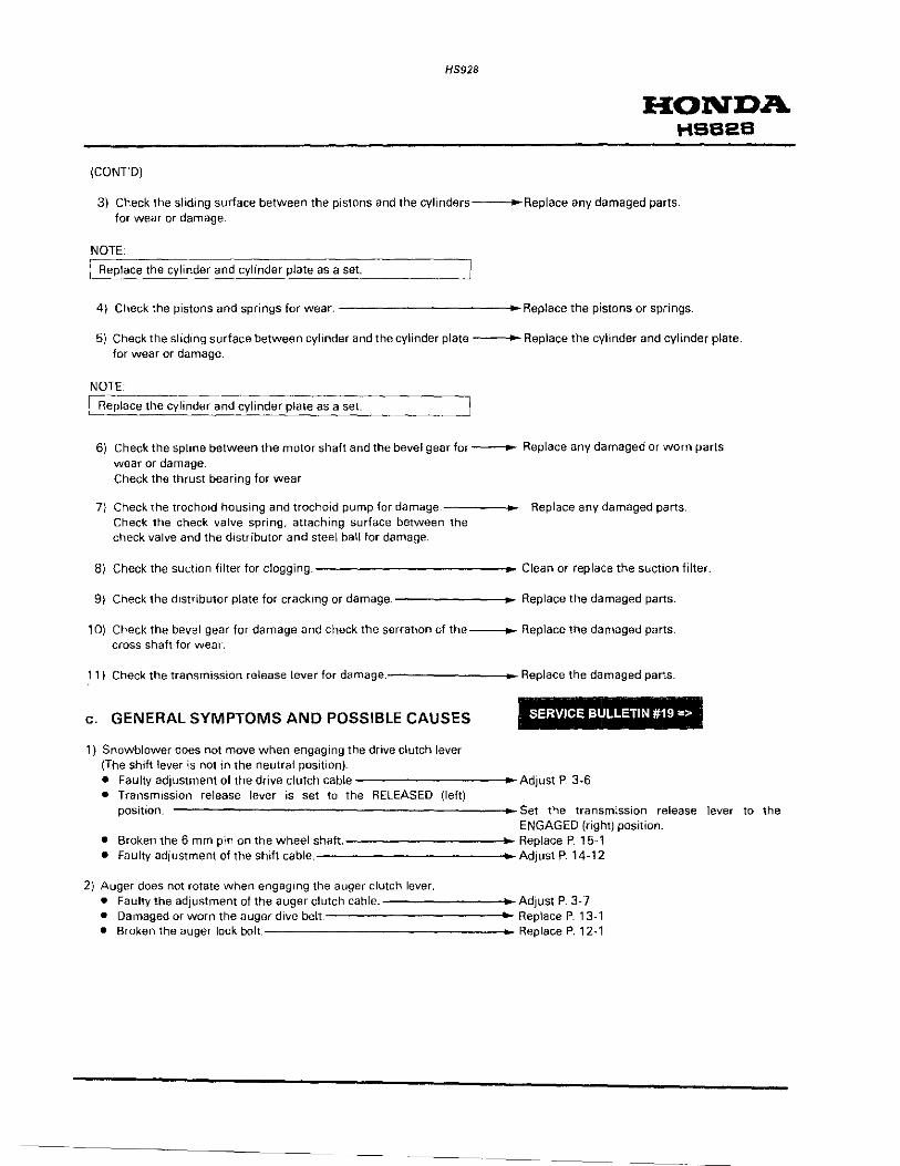
3) Check the sliding surface between the pistons and the cylinders---+-Replace any damaged parts. for wear or damage.
NOTE [ Replace the cylinder. and cylinder plate as a set.
4) Check the pistons and springs for wear. -----------_.Replace the pistons or springs.
5) Check the sliding surface between cylinder and the cylinder plate -----Replace the cylinder and cylinder plate. for wear or damage.
NOTE
LCR~e~p~la~c~e~t~h~e~c~y~li~n~d~er~an~d~c~yl~in~d~e~r~p~l~at~e~a~s~a~s=e=t.-------J
6} Check the spline between the motor shaft and the bevel gear for~ Replace any damaged or worn parts wear or damage. Check the thrust bearing for wear.
7) Check the trochOid housing and trochoid pump for damage.-----+Check the check valve spring, attaching surface between the check valve and the distributor and steel ball for damage.
Replace any damaged parts.
8) Check the suction filter for clogging.-------------. .. Clean or replace the suction filter.
9) Check the distributor plate for cracking or damage.--------- Replace the damaged parts.
1 0) Check the bevel gear for damage and check the serration of the---- Replace the damaged parts. cross shaft for wear.
1 1) Check the transmission release lever for damage.--------..- Replace the damaged parts .
c. GENERAL SYMPTOMS AND POSSIBLE CAUSES
1) Snowblower does not move when engaging the drive clutch lever (The shift lever is not in the neutral position).
. .
SERVICE Bl)LLETIN #19 =>
• Faulty adjustment of the drive clutch cable -----------Adjust P. 3.6 • Transmission release lever is set to the RELEASED {left)
position. -----------------------+-Set the transmission release lever to the ENGAGED (right) position.
• Broken the 6 mm pin on the wheel shaft.------------o~ Replace P. 15-1 • Faulty adjustment of the shift cable. Adjust P. 14-12
2) Auger does not rotate when engagmg the auger clutch lever. • Faulty the adjustment of the auger clutch cable.--------•Adjust P. 3·7 • Damaged or worn the auger dive belt Replace P. 13-1 • Broken the auger lock bolt Replace P. 12-1
-·--------

HONDA HSB2B
3) Chute does not operate. (Up and down)
HS928
• Damaged of faulty adjustment of the chute guide cable.-----+- Adjustment P. 3-5 Replace P 17-2
Emergency procedure: Remove the chute guide cable adjustment nut, and remove the chute guide bolts. Remove the collars between the chute guide and its bolts. Set the angle of the chute guide as desired. Tighten the chute guide bolts and adjustment nut in order to fix the chute guide.
I - -
{Right and left) SERVICE BULLETIN #19 =>
• Incorrect clearance between chute drive gear and the chute ring gear. Adjust P. 1 1-2
• Damaged or worn chute gears.---------------- Replace P. 11-1 • Broken pins of the chute crank. Replace P. 11-1 Emergency procedure: Remove the chute drive gear bracket. Set the angle of the chute as desired and install the chute drive gear bracket.
4) Snow is not thrown from the chute. • Clogged snow in the chute.----------------4~ Remove the snow using a stick. • Broken blower shear bolt. Replace P. 1 2-1 • Cut auger belt. Replace P. 13-1
5) Abnormal sound is heard or abnormal vibration is ielt. • Loosen each bolt and nut.----------------- Retighten.
6) Track slips. • Track tension is insufficient.---------------- Adjust P. 3-4
------------------

HS928
• PERFORMANCE TEST
CAUTION:
[ Perform this test on the asphalt is wet.
1) Start the engine and adjust the maximum engine speed (P.
3-9).
Maximum engine speed: 3,600 ± 150 min-1 (rpm)
2) Run the snowblower at maximum speed for a few minutes to raise the oil temperature in the hydrostatic transmission.
3) Position the shift lever to obtain the following speed:
DISTANCE TIME
1 m (3.3 ft) 5-8 second
4) Place the snowblower against the wall as shown, and position the shift lever as 1n step 3.
5) Check that the tracks slip aga1nst the floor when the drive clutch 1s engaged.
CAUTION:
LDo. not slip the tracks for mor':_ than fiv'-'e"'-'m:::i:::n_:u.:_te,s:::· ______ ___J
HONDA HSB2B
NEUTRAL (N)
SHIFT LEVER
WOOD BLOCK

HONDA HSS2S
LUBRICATION POINTS
CHUTE GUIDE
.-.&a
CHUTE DRIVE GEAR AND RING GEAR
HS928
CLUTCH LEVER
LEVERS
.-, SLIDING SURFACE •• SliDING SURFACE
...... , SliDING ---= fW SURFACE · '

HONDA HS624·HSB28
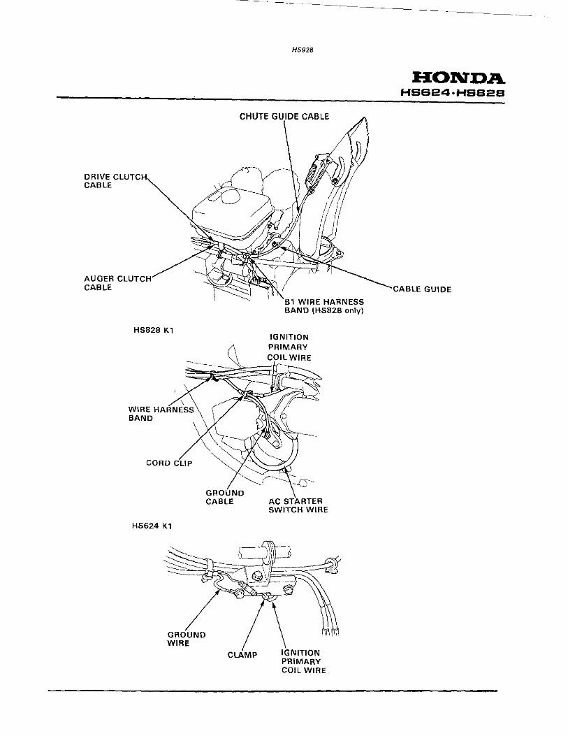
3. CABLE/HARNESS ROUTING
DRIVE CLUTCH CABLE
AUGER CLUTCH CABLE
\ \ '
WIRE HARNESS BAND
\\ ----\----)
i~-1 ! ; r / r I __./ I / ,~---LL_ __ -.:s_.~__.
SHI CABLE
HS928
THROTTLE CABLE
ENGINE SWITCH WIRE
SHIFT CABLE
BAND
THROTTLE CABLE
~DRIVE GUIDE CABLE
CHUTE GUIDE CABLE
WIRE HARNESS BAND

HONDA HS724 · HS928
HS92B
3. CABLE/HARNESS ROUTING • TA and WA types only
ENGINE STOP SWITCH
DRIVE CLUTCH CABLE
(clamped)
CHUTE HANDLE / CHUTE GUIDE CABLE
/
(not clamped)
Sl"\----' \ /L , e \ /;~:::: . --=-., ~
,)
~/ :- .,,
""' '·", IGNITION COIL I
AUGER CLUTCH CABLE
(clamped) GROUND TERMINAL
WIRE
DRIVE C CABLE
AUGER CABLE
HSBZB K1
HS624 K1
GROUND WIRE
CHUTE
GROUND CABLE
CLAMP
HS928
CABLE
1 WIRE HARNESS BAND (HSBZB only)
IGNITION PRIMARY
AC STARTER SWITCH WIRE
HONDA HSB24•HSS2S
._CABLE GUIDE

3181f:J 31J.J.OIJHJ.
38nJ. !JNIJ.:J3J.Oild
BCIBSH • too89SH
YQNOH 9Z6SJ..I

3. MAINTENANCE
[~~_MAINTENANCE ~CHE':ULE_
1. MAINTENANCE SCHEDULE SERVICE PERIOD 121
l Perform at every indicated year or operating
-·-·--·
hour interval, whichever comes first.
·~---Engine oil -- - -~~~~-<?-~. l~vel _.
_ i __ __ _L~hange _
-~eplace
1
' Transmtsston 011
• Spark plug
Auger sktd shoes and Check-Readjust scraper
- ---···--T_ra_ck _____ . ____ . __ A_cji~
Tires Check
Auger and blower shear Check bolts
I Bolts, nuts, f~-~teners ~- ·check j' ·------ -- .. -~-----------.I Sediment cup Clean
HS928
-------
EVERY YEAR
EACH USE
FIRST 20 HRS. BEFORE
OPERATION OPRATION
0
HONDA HS724 ·HS928
REFER TO
PAGE
3-2131
3-3 131
3-3 131
12-4 131
3-4131
3-4 131
-r-~:0~~~~i-~-nd _c~rbure-t~·;_--__ o~_-___ --~~ • Idle speed __ __ Chec~-Adjust ____
1
__ 1
__ J· ' ·--. _
______ A£ply _,;! 2-20 131 c~eck.:_Readjust _____ -(; 111-r--__ [. 3-5131
3-4 131
3-6131
3-5 131.3·1 141 u
Chute glJide control cable 1 A_~.er clutch cable
Drive clutch cable
Throttle cable
Ch."_ck-Re_adjust +-~ i ( 111 ' ' 3-7 131
~~:~t:_:::~[:: ----j~-= 1 ~;:~i--f -~ f~~-- -+-------!
• Fuel line
• Valve clearance
• Fuel tank and filter
• Emission related items.
Check (Replace Every 2 years if necessary)
---Check-Re_adju~
Clean
{ 1) These items may require more frequent inspection and replacement under heavy use.
0 0
{2) For professional commercial use, log hours of operation to determine proper maintenance intervals. 131 See the base HS828 shop manual. 141 See the HS1132 supplement.
3-6131
3-12131
3-6 131

•
HS928
ENGINE OIL OIL LEVEL CHECK
NOT.c::E.:_• __ ---------------:-----:~-, Drain1ng can be performed more rapidly and completely while I the engine ts still wa:crc.mc.c.. ------------
1) Place the snowblower on a level surface. 2) Unscrew the oil filler cap/dipstick. and wipe it dry. 3) Insert the oil filler cap/dipstick all the way in, then remove it
and read the engine oil leveL
NOTE.
~~.-t.a-~o-0t-3s-~-~-~w-.:.-;;d~-~flller cap/dipstick In, otherw1se you ~'IJ
4) If the engine oil level is low, fill to the top of the oil filler neck with the recommended oil Do not overfill.
~commended engine oil
OIL CHANGE
Us~ Honda 4~stroke oil or an equiva-i~nt I high-detergent, premiurn quality motor oil I certified to meet or exceed U.S. auto~ ' mobile manufacturer's requirements for Service Classification SG, SF/CC, CD. Motor oils classified SG, SF/CC, CD. will show this designation on the container. SAE 5W-30 is recommended for general, all temperature use. Other viscosities shown in the chart may be used when the average temperature in your area is within the indicated range.
NOTE _____________________ _
,!. Dram the engine oil with the engine warm and the snowblower on level ground to assure complete and rapid
L draining. -·--- ---------'
1) With the engine stopped. Remove the 01! filler cap/dipstick and drain bolt Allow the oil to drain completely.
2) Remstall the dram bolt and tighten to the spec1fied torque.
TORQUE: 23 N·rn (2.3 kg-rn, 17 ft-lbl
3) Fill the crankcase w1th the recommended engme oi1 to the outer edge of the oil filler neck. Remsta!l the filler cap/dipStick
r-
L___ Engme 011 cpoacity 111(116USqt,o.971mpqt) J 4) Reinstall the oil filler cap/dipstick and tighten it securely
CAUTION:
~ • Do not overfill with engine oil. ~
I • Check the engine oil with the snowblower on level ground.
•1
• Used engine oil may cause skin cancer if repeatedly left in I' co.n~act ~ith the skin for prolonged periods. Although .th~s •s unllkely unless you handle used oil on a daily basis It •s still advisable to thoroughly wash your hands with I
:_____ soap and wat~~~~~~ as possible after handing ~~ed oil~_j
HONDA HSS2B
OIL FILlER CAP/DIPSTICK
UPPER LEVEl
--= OIL I 5W-30 i
I ·~===="!"!·)
I ' I
I I
I -20 0 20 40 50°F
-30 -20 -10 0 10°C
DRAIN BOLT
HONDA HSB2B
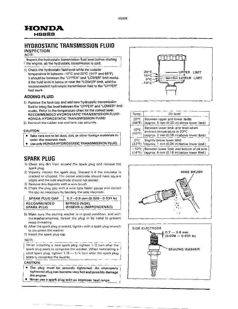
HYDROSTATIC TRANSMISSION FLUID INSPECTION NOTE:
Inspect the hydrostatic transmission fluid level before starting the engine, as the hydrostatic transmission is cold.
1 J Check the hydrostatic fluid level while the outside temperature is between -10"C and 20"C (14"F and 68"F).
HS928
It should be between the "UPPER" and "LOWER" limit marks. If the fluid level is below or near the "LOWER" limit, add the recommended hydrostatic transmission fluid to the "UPPER~ limit mark.
ADDING FLUID 1) Remove the tank cap and add new hydrostatic transmission
fluid to bring the level between the "UPPER" and "LOWER" limit marks. Refer to the temperature chart for the correct level. RECOMMENDED HYDROSTATIC TRANSMISSION FLUID: HONDA HYDROSTATIC TRANSMISSION FLUID
2) Reinstall the rubber cap and tank cap securely.
CAUTION· --------------,--:------, • Take care not to let dust, dirt, or other 'foreign materials to
enter the reservoir tank. o Use only HONDA HYDROSTATIC TRANSMISSION FLUID.
SPARK PLUG 1) Clean any dirt from around the spark plug and remove the
spark plug. 2) Visually inspect the spark plug. Discard it if the insulator is
cracked or chipped: The center electrode should have square edges and the s1de electrode should not eroded.
3} Remove any deposits with a wire brush. 4) Check the plug gap With a wire-type feeler gauge and correct
the gap as necessary by bending the side electrode.
~:~~~:;EL~~E~AP Ts~~~~~;;K:~·o2s~~031in} SPARK PLUG W16EPR-U (NIPPONDENSO)
5) Make sure the sealing washer is in good condition, and with thewasherattached, thread the plug in by hand to prevent cross-threading.
6) After the spark plug ts seated, tighten with a spark plug wrench to compress the washer
7) Install the spark plug cap
NOTE
When installing a new spark plug, tighten 1/2 tur~~er th~ spark plug seats to compress the washer. When reinstalling a used spark plug, tighten 1/8- 1/4 turn after the spark plug seats to compress the washer.
CAUTION;
• The plug must be securely tightened. An improperly tightened plug can become very hot and possibly damage the engine.
• Never use a spark plug with an improper heat range.
Temp.
20"C 168"F)
10"C (50°F)
o;c 132"F)
-10°C (14"F)
SIDE
Oil level
Between upper and lower limits
LIMIT
LIMIT
(approx. 5 mm (0.20 in) above lower limit)
Between lower limit· and level when , ambient temperature is 20°C (approx. 2 mm (0.08 in)above lower limit)
Slightly below lower limit (approx. 1 mm (0.04 in) below lower limit)
Between lower limit and bottom of oil tank {approx. 4 mm (0.16 in) below lower limit}
WIRE ~t<U~,H
SEALING WASHER
HS928
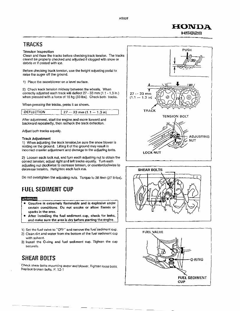
TRACKS Tension Inspection Clean and thaw the tracks before checking track tension. The tracks cannot be properly checked and adjusted if clogged with snow or debris or if coated with ice.
Before checking track tension, use the height adjusting pedal to raise the auger off the ground.
1) Place the snowblower on a level surface.
2) Check track tension midway between the wheels. When correctly adjusted each track will deflect27- 33 mm (1.1 - 1.3 in.) when pressed with a force of 15 kg (331bs). Check both tracks.
When pressing the tracks, press it as shown.
I DEFLECTION ) 27 - 33 mm (1.1 - 1.3 in)
After adjustment, start the engine,and move forward and backward repeatedly, then recheck the track deflection.
Adjust both tracks equally.
Track Adjustment 1) When adjusting the track tension, be sure the snow blower is resting on the ground. Lifting it of the ground may result in incorrect crawler adjustment and damage to the adjusting bolts.
2) Loosen each lock nut, and turn each adjusting nut to obtain the correct tension; adjust right and left tracks equally. Tum each adjusting nut clockwise to increase tension, or counterclockwise to decrease tension. Retighten each lock nut.
Do not overtighten the adjusting nuts. Torque to 38 N•m (27 ft-lbs).
FUEl SEDIMENT CUP
• Gasoline is extremely flammable and is explosive under certain conditions. Do not smoke or allow flames or sparks in the area.
• After instaiUng the fuel sediment. cup, Check for leaks, and make sure the area is dry before starting the engine.
1) Set the fuel valve to '"OFF" and remove the fuersediment cup. 2) Clean dirt and water from the bottom of the fuel sediment cup
with solvent. 3) Install the 0-ring and fuel sediment cup. Tighten the cup
securely.
SHEAR BOlTS ·check shear bolts mounting auger and blower. Tighten loose bolts Replace broken bolts. P. 12-1 .
--·--
HONDA HS828
PUSH
LJM-t ~ ~--·
TRACK
TENSION BOLT
LOCKNUT
SHEAR BOLTS
FUEL VALVE
ADJUSTING NUT
FUEL SEDIMENT CUP
HONDA HSB2B
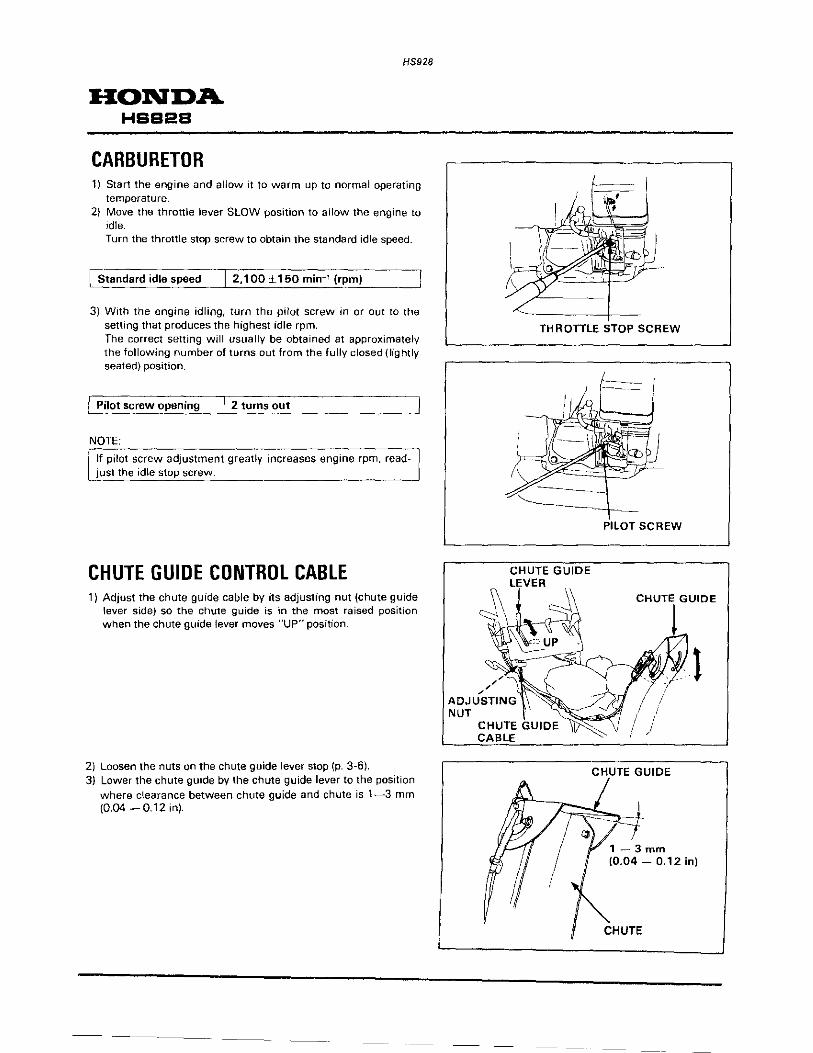
CARBURETOR
HS928
1) Start the engine and allow it to warm up to normal operating temperature.
2) Move the throttle lever SLOW position to allow the engine to idle. Turn the throttle stop screw to obtain the standard idle speed.
[Standard idle speed I 2,1 00 ±150 min-' (rpm)
3) With the engine idling, turn the pilot screw in or out to the setting that produces the highest idle rpm. The correct setting will usually be obtained at approximately the following number of turns out from the fully closed (lightly seated) position.
I Pilot screw opening I 2 turns out
NOTE:
If pilot screw adjustment greatly increases engine rpm, readjust the idle stop screw.
CHUTE GUIDE CONTROL CABLE 1) Adjust the chute guide cable by its adjusting nut (chute guide
lever side) so the chute guide is in the most raised position when the chute guide lever moves "UP" position.
2) Loosen the nuts on the chute guide lever stop (p. 3-6). 3) Lower the chute guide by the chute guide lever to the position
where clearance between chute guide and chute is 1-3 mm (0.04 - 0.12 in).
------
\\
THROTTLE STOP SCREW
CHUTE GUIDE LEVER
PILOT SCREW
CHUTE GUIDE
1- 3mm (0.04 - 0.12 in)
CHUTE

HS928
4) Position the stop against the chute guide lever, and tighten the nuts
SERVICE BULLETIN #22 =>
FUEL TANK/FUEL FILTER
• Gasoline is extremely flammable and is explosive under
I o
certain conditions. Do 'not smoke or allow flames or sparks in the area. After installing the fuel tank and filter, check for leaks, and make sure the area is dry before starting the engine.
1) Remove the fuel tank after drain the gasoline from the fuel tank completely
2) Disconnect the fuel tube and remove the fuel filter. 3) Clean the fuel tank with solvent and dry the fuel tank
completely. 4) Clean the fuel filter with compressed air and check it for
damage. 5) Place the 0-ring on the filter and reinstalL
Tighten the fuel filter to specifed torque TORQUE: 2 N·m (0.2 kg-m, 1.4 ft-lb)
DRIVE BELT 1. DRIVE CLUTCH LEVER STROKE
ADJUSTMENT 1) Depress the drive clutch lever gradually and adjust so that the
drive clutch lever stroke is 140- 143 mm (5.5 -5.6 in) at the point where the pulley starts to move.
2) To adjust the drive clutch lever, loosen the clutch cable lock nut and turn the adjusting nut.
After adjustment. tighten the lock nut securely and recheck the drive clutch lever stroke.
Start the engine, and make sure that the drive belt does not rotate when the drive clutch lever is disengaged.
HONDA HSB2B
CHUTE GUIOE LEVER
!'C'!c:===
ORIVE CLUTCH LEVER
LOCK NUT
0-RING
140 ~ 143 mm )5.5 - 5.6 inl

HONDA HSS2S
2. DRIVE BELT TENSION ADJUSTMENT 1 I Adjust the belt stoppers (P 3-1 1 I
HS928
2) Check the distance between the drive tension roller and engine head as shown is 171 ~ 174 mm (6.7- 6.9 in) when the drive clutch lever is disengaged. To adjust the distance, loosing the drive clutch cable lock nut and turning the adjusting nut.
3) After adjustment, tighten the lock nut securely and recheck the distance.
Start the engine, and make sure that the drive belt does not rotate when the drive clutch lever is disengaged.
AUGER BELT 1. AUGER TENSION ROLLER POSITION
ADJUSTMENT 1) Adjust the auger tension roller with the long hole in the tension
arm so that the tension roller comes to the complete outside (cable side) position.
NUT
AUGER TENSION ROLLER
DRIVE CLUTCH CABLE
PULLEY
TENSION~ ~\f'r. ARM ~~
AUGER TENSION ROLLER
OUTSIDE (CABLE SIDE)
INSIDE (ENGINE SIDE)

2. AUGER CLUTCH LEVER STROKE ADJUSTMENT
1) Depress the auger clutch lever gradually and adjust so that the auger clutch lever stroke is 140-143 mm (5.5 -5.6 in) at the point where the auger tension roller starts to move. Adjustment should be made by loosening the auger clutch cable lock nut and turning the adjusting nut.
2) Start the engine and check the belt. When the auger rotates; Set the belt stopper to the standard position so that it does not contact with the belt stopper (P. 3-11 ). When the auger slips; Slide the auger tension roller to the center.
NOTE:
• Make sure that the belt rotates whenever you slide the auger tension roller to the center.
1 • When replacing the belt with a new one, it is not necessary L to slide the auger tension roller to the center.
3. AUGER CLUTCH LEVER ADJUSTMENT
To adjust the auger clutch lever affects the function of the drive clutch operating together with the auger clutch and the bell tension. Be sure to adjust as following; 1) Depress the auger clutch lever. 2) Depress the drive clutch lever. 3) Release the auger clutch lever and lock it while keeping the
drive clutch depressed. 4) Adjust the auger clutch lever so that the clearance between the
tip of the auger clutch lever and the handle grip is 10-15 mm (0.4- 0.6 in). Adjustment can be made by loosening the two cap nuts and moving the lever.
5) After the adjustment, tighten the cap nuts securely and relock the auger clutch lever. Make sure that the clearance is as specified.
4. AUGER BRAKE ADJUSTMENT
1) Start the engine and rotate the auger with the auger clutch lever depressed. Engine speed should be as below.
[Engine speed I 3,600 min-1 (rpm} ~-------~~------~~------~
2) Release the auger clutch lever and make sure that the auger stops rotating within 5 seconds.
3) If not, loosen the auger clutch cable and adjust so as to stop within 5 seconds.
NOTE:
je Be sure that the clutch lever stroke is as specified in step 2. I _ in the previous page while adjusting the auger clutch cable. ~ __ B_e_s_u_r_e_t_o_fo __ llo_w __ i_n_o_rd_e_r_o_f_s_t_e~ps __ 1_._•h_r_o~u~g_h_4_. ________ ~
H5928
140- 143 mm (5.5- 5.6 in)
HONDA HSB2B
LOCK NUT
ADJUSTING NUT
OUTSIDE (CABLE SIDE)
INSIDE (ENGINE SIDE)
10-15mm (0.4 - 0.6 in)
T
AUGER TENSION ROLLER
AUGER CLUTCH LEVER
AUGER DRIVE .

HS928
HONDA HSS2S
THROlTLE/CHOKE CABLE Adjustment of the throttle cable interlocked choke is as follows:
1. MAXIMUM ENGINE SPEED ADJUSTMENT
1) Remove the air cleaner cover, air intake cover and control cover.
NOTE: Install the 6 mm cap nut that tightening the control cover and air cleaner elbow securely after remove the control cover.
2) Loose the adjusting screw Q) and 0 to such an extent that they are not removed.
3) Start the engine, and move the throttle control lever to "FAST" position. Loose the lock nut of the throttle cable (handle side).
4) Adjust the maximum engine speed by adjusting nut as follows;
( Maximum engine speed / 3.600 ± 150 min-1 (rpm)
After adjustment tighten the lock nut securely.
5) Tighten the adjusting screw 0 to attach the control lever.
NOTE:
I Do not overtighten the screw®-
AIR CLEANER COVER
ADJUSTING SCREW (j)
ADJUSTING SCREW (j)
THROlTLE CONTROL LEVER
~ ADJUSTING SCREW (j)
= -~§i.";AST" ':\:\ }\
., .. "START (CHOKE)"
rv-- LOCK NUT

HS928
<STANDARD IDLE SPEED> 6) Move the throttle control lever to "SLOW" position and adjust
the standard idle speed by adjusting screw CD as follow;
STANDARD IDLE SPEED: 2,100 ± 150 min-1 (rpm)
NOTE: __________________________________ __
~st the choke rod after adjusting the maximum engine
~~~------------------------------~
2. CHOKE ROD ADJUSTMENT
1) Stop the engine and loosen the adjusting screw 0 to such an extent that it is not removed.
2) Move the throttle control lever to "FAST" position. Bend the choke rod at point A in order to make the clearance between the speed control lever and choke lever 0- 5 mm {0 ~0.02 in).
HONDA HSB2B
ADJUSTING SCREW (i)
I ADJUSTING SCREW (i)
SPEED CONTROL LEVER
CHOKE ROD

HS928
HONDA HSS2B
3) Push the choke lever to the fully closed position (see directional arrow in the illustration). Move the throttle control lever to "START (CHOKE)" slowly, and stop when the speed control lever and choke lever contact.
NOTE:
Push the choke lever toward the horizontal position.
4) Turn the adjusting screw <D to contact the speed control lever. Return the adjusting screw <D to 1/8 - 1/4 turns from the contact position.
5) Make sure that carburetor choke valve is fully closed when the speed control lever is moved. If the carburetor choke valve is not fully closed, adjust the choke rod again from step 2).
6) Install the control cover, air intake cover and air cleaner cover. Start the engine, and make sure the maximum engine speed and standard idle speed are correct.
SPEED CONTROL LEVER
ADJUSTING SCREW (j)

HS928
MAINTENANCE HONDA HSS24•HSB28
r----~~ BELT STOPPER L_ ________________________ __
1. BELT STOPPER ENGINE SIDE NOTE: I Adjust the belt stopper after adjusting the drive clutch lever
\_:_~~~-ke __ ~~n~ -~uger ~~~~e~elt ~~ns~~_:-~_ __ ___ _ _ ____ _
1) Remove the belt cover. 2)Adjust the clearance between the belt stopper/belt guide
and drive belt by loosening the bolt and nut with the drive clutch lever depressed.
CLEARANCE SPECIFICATION:
[BELT STOPPER 1-3 mm (0.04-0.12-:-in-')----j
i BELT GUIDE 3-5 mm (0.12-0.20 in)
3)Adjust the clearance between the belt stopper/belt guide and auger belt by loosening the bolt and nut with the auger clutch lever depressed.
CLEARANCE SPECIFICATION: ,-------1
1 BELT STOPPER HS624 : 4-6 mm (0.16-0.24 in) HS828 : 1-3 mm (0.04-0.12 in)
~B_~_L T G U·I·D· E HS624 : 4-6 mm (0 .16-0.24 in) _ HS828: 3-5 mm (0 .12-0.20 in) ___ , ___ _
After the adjustment, start the engine and make sure that the belts do not rotate with the clutch disengaged.
BELT GUIDE
STOPPER
ELT GUIDE

HS928
2. AUGER SIDE
1) Remove the auger housing (P. 12-3). 2) Adjust the belt support position by loosening the nut so that,
with the auger drive belt tensioned by hand, the clearance between the belt and the right and left belt supports are as specified below.
RIGHT BELT SUPPORT: 2.0 ± 1.0 mm (0.08 ± 0.04 in) LEFT BELT SUPPORT: 4.0 ± 1.0mm (0.16 ± 0.04 in)
After the adjustment. start the engine and make sure that the belt does not rotate with the clutch disengaged.
VALVE CLEARANCE NOTE:
• Valve clearance inspection and adjustment must be performed with the engine cold.
1) Remove the cylinder head cover, and set the piston at top dead center of the compression stroke (both valves full closed}. The triangular mark on the starter pulley will align w1th the top hole on the starter cover when the piston is at top dead center of the compression or exhaust stroke.
NOTE
~---;-Mo~-~~h;--~~~~- ;arter. and make sure that triangular markl
1 ___ ~ ~-~~~~ed_~!_~~op _hoi~~~-~~~ st~~er cove~---~-'
2) Insert a feeler gauge between the rocker arm and valve to measure valve clearance.
IN 0.15 ± 0.02 mm l V-A-LV-·E·--C-l_E_A_R __ A_N_C_E _ __t_f-_--~--~-.Lf-.'-'-~:-~~
0
0-=0
::_:::6
::_±-~±=:o_. ~'-'~-=o-=:"1
m...:i:cn I'- _,1 _ EX (0.008 ± 0.001 in)
3) If adjustment is necessary, proceed as follows: a. Holding the rocker arm pivot and loosen the pivot lock nut. b Turn the rocker arm pivot to obtain the specified clearance. c. Tighten the lock nut to the specified torque while holding
the rocker arm pivot. TORQUE: 10 N·m (1.0 kg-m, 7 ft-lb)
d. Recheck valve clearance after tightening the lock nut
LEFT BELT SUPPORT
HONDA HSBeB
ROCKER ARM
RIGHT BELT SUPPORT
ROCKER ARM PIVOT
ROCKER ARM PIVOT LOCK NUT
To increase valve clearance, screw out. To decrease valve clearance, screw in.

HS928
HONDA HBB2B ENGINE REMOVAL/INSTALlATION 1. ENGINE REMOVAL/INSTALLATION
ENGINE REMOVAL/INSTALLATION 1) Remove the 6 x 12 mm flange bolt, collars and belt cover. 2) Remove the chute guide cable from the chute guide. 3) Remove the 8 x 28 mm flange bolt, 8 mm washer, drive pulley (drive and auger) and woodruff key.
NOTE:
! Be careful not to lose the woodruff key.
4) Remove the 6 x 12 mm flange bolt from the chute handle.
NOTE:
Engine can be removed without removing the chute handle holder and chute drive gear.
5) Disconnect the engine switch wire and ground cable. 6) Disconnect the throttle cable from the control plate. 7) Remove the four 10 mm flange nuts, and remove the engine.
GROUND CABLE
10 mm FLANGE NUT
HANDLE HOLDER---',-y BOLT
6 X 12
TH CABLE
ENGINE SWITCH
I ADJUSTMENT; P. 3-9)
--------
WOODRUFF KEY
AND AUGER BELTS
8 X 28
CHUTE GUIDE CABLE
)ADJUST8MENT: P. ~
I I

• •
HS928
FUEL SYSTEM HONDA HSB2B
1. AIR CLEANER 3. FUEL TANK/GOVERNOR 2. CARBURETOR
AIR CLEANER a. DISASSEMBLY /REASSEMBLY • Air cleaner disassembly/reassembly can be made with the engine installed in the frame .
BREATHER TUBE IREASSEM_B_LY-:------~
I Aft.er installing on the air cleaner elbow, insert into the hole in the 1~9YI~n~:_!~~~ cover. ____ __j
6 X 35
CARBURETOR SPACER
REASSEMBLY: Check for damage and install. Note the installation direction.
VIEW FROM THE AIR CLEANER SIDE
CLEANER CAP
f""f-------- 6 x 8 mm
6 CAP NUT (2}
PAN SCREW
6 X 8 (21
AIR INTAKE COVER
REASSEMBLY: Install as shown.
AIR INTAKE COVER
GROMMEN~ PROTECTING
~t==;) TUBE
THROTTLE LEVER CARBURETOR SIDE SIDE
AIR CLEANER ELBOW
DISASSEMBLY /REASSEMBLY: • Remove and install with the choke lever and
fuel valve in the ""ON'' position. • Clean the inside of the elbow with com
pressed air before installation.

HONDA HSB2B
CARBURETOR SERVICE BULLETIN #10 =>
a. REMOVAL/INSTALLATION
1) Remove the air cleaner elbow (P. 5-2)
HS928
THROTTLE RETURN SPRING
REASSEMBLY: • Pass the throttle return spring
through the governor rod and hook it with its end to small hole of the carburetor throttle arm.
• Short, straight end goes toward the carburetor side
FUEL TUBE
INSULATOR PACKING
CHOKE ROD
FUEL VALVE
CARBURETOR PACKING
INSPECTION: P 5-3 DISASSEMBLY:
CARBURETOR INSULATOR
REASSEMBLY: • Blow out the passages with compressed air
(30 psi or less) and install, noting the installation direction.
• After installation, connect the spark plug wire and fuel tube securely.
HIGH CORD
Unhook the thronle return spring. Pull the carburetor forward to a point where the groove in the throttle arm lines up with the governor rod. and lift the governor rod out of its hole. Reassembly is in the reverse order of disassembly.
GROOVE
THROTTLE
HS928
HONDA HSS28
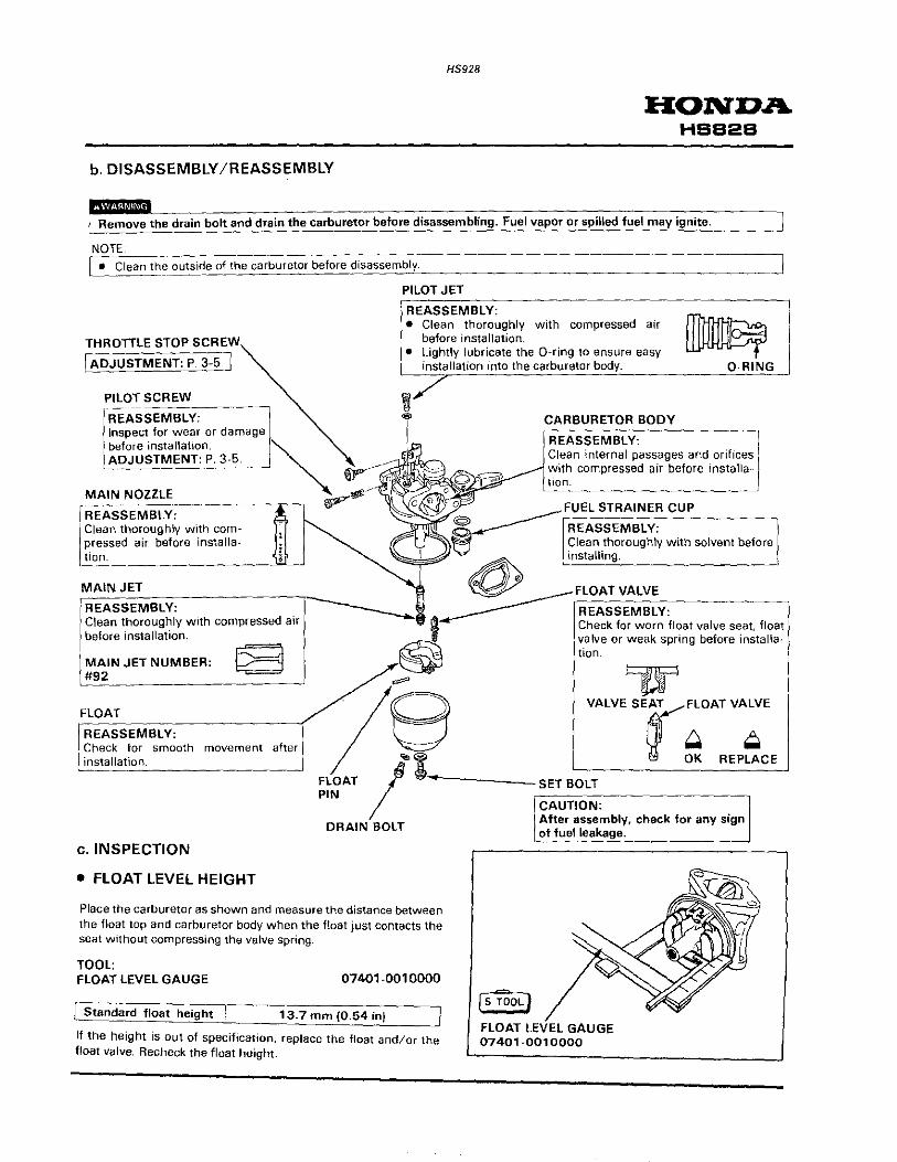
b. DISASSEMBLY /REASSEMBLY
Remove the drain bolt and drain the carburetor before disassembling. Fuel vapor or spilled fuel may ignite.
NOTE • Clean the outside of the carburetor before disassembly.
PILOT JET
REASSEMBLY:
THROTTLE STOP SCREW
I ADJUSTMENT: p 3-5 I
• Clean thoroughly with compressed air before installation.
• Lightly lubricate the 0-ring to ensure easy installation into the carburetor body.
MAIN JET
'«/ i
REASSEMBLY: ------.....· Clean thoroughly with compressed air before installation.
MAIN JET NUMBER: #92
FLOAT
REASSEMBLY: Check for smooth movement after installation.
c. INSPECTION
• FLOAT LEVEL HEIGHT
Place the carburetor as shown and measure the distance between the float top and carburetor body when the float just contacts the seat without compressing the valve spring.
TOOL: FLOAT LEVEL GAUGE 07401-0010000
/ Standard float height 13.7 mm (0.54 in)
If the height is out of specification, replace the float and/or the float valve. Recheck the float height.
CARBURETOR BODY
REASSEMBLY:
Is T"8oL) FLOAT LEVEL GAUGE 07401-0010000
~ 0-RING
HS928
HONDA HSS2S
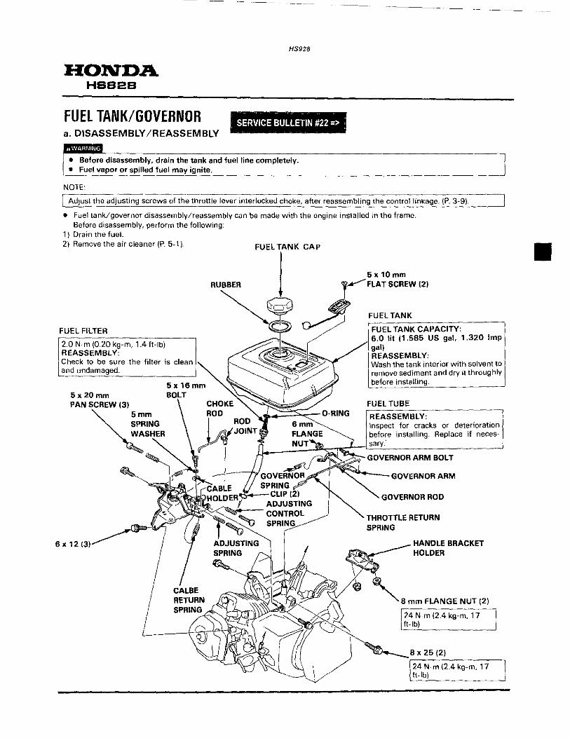
FUEL TANK/GOVERNOR SERVICE BULLETIN #22 => a. DISASSEMBLY /REASSEMBLY
• Before disassembly, drain the tank and fuel line completely. • Fuel vapor or spilled fuel may ignite.
NOTE:
I Adjust the adjusting scre~s of the throttle lever interlocked choke, after reassembling the control linkage_ (P. 3-9).
• Fuel tank/governor disassembly/reassembly can be made with the engine installed in the frame. Before disassembly, perform the following:
1) Drain the fuel. 2) Remove the air cleaner (P. 5-1}. 1=111=1 TANK CAP
FUEL FILTER
2.0 N-m (0.20 kg-m, 1.4 ft-lb) REASSEMBLY: Check to be sure the filter is clean and
5x20mm
PAN S~CREW (31 mm
RING ASHE
6x12
RUBBER
CHOKE ROD
5 x 10 mm FLAT SCREW (2)
FUEL TANK
FUEL TANK CAPACITY: 6.0 lit (1.585 US gal, 1.320 Imp gal) REASSEMBLY:
the tank interior with solvent to sediment and dry it throughly
IIi
I II'VI ~g~Tl FLANGE ~ I befo~e installing. Replace if neces-
~~ _ NUT~ ___ sarv~-------------------~ I >.:;._ --··------------·-
~GOVERNOR ARM
GOVERNOR ROD
THROTTLE RETURN SPRING
HANDLE BRACKET HOLDER
8 mm FLANGE NUT (2)
~ m (2.4 kg-m, 17 ft-lb)
. m (2.4 kg-m. 17
•

HS928
RECOIL STARTER/FAN/MUFFLER
~. RECOIL STARTER/FAN COVER 2. MUFFLER
RECOIL STARTER/FAN COVER a. REMOVAL/INSTALLATION
• Wear gloves and eye protection. • During disassembly, take care not to allow return spring to come out.
• Recoil starter/fan cover removal/installation can be made w1th the eng1ne installed in the frame
Before disassembly, perform the following: 1) Remove the AC starter switch housing (P. 18-1 ).
b. DISASSEMBLY
STARTER ROPE
REASSEMBLY: Check the rope for fraying or wear before installation If installing a new rope, oil the rope before installation
STARTER CASE
FAN COVER
RETURN SPRING ~---------- --- --·-----=-1· :CAUTION: 'Wear gloves to protect your hands. REASSEMBLY: Hook the outer hook m the groove of the starter reel and inner hook on the starter case tab.
STARTER REEL
RECOIL STARTER
lREASSEMBLY: I R~move dirt and debris before installation. Position the recoil starter case fo. r best j starter grip location. -····· __
"'!illJ 6 X 8 (2)
()
RATCHET --------------, REASSEMBLY: REASSEMBLY:
case alter 1 1 Check for wear or damage. Install instal
Note the installation direction
RATCHET
~ STARTER REEL
SPRING COVER BOLT ,.:, REASSEMBLY:
~ @OIIJ ~ Apply a locking agent to the '1
I ~a~~ threads. ____j
\~FRICTION PLATE B
STARTER REEL COVER FRICTION ~------ ·-PLATE A REASSEMBLY:
Align the ratchet with the reel cover notch.

c. REASSEMBLY
• RECOIL STARTER ASSEMBLY
The recoil rope must be oiled prior to installation to prevent freezing, which may make the recoil starter inoperative
1) Cut 137 em (54 in) of #5 recoil rope from your bulk supply.
2) Soak the recoil rope in engine oil.
3) Use a shop towel and squeeze the excess oil from the rope.
4) Pass the rope through the hole in the starter reel, and tie the end of the rope. Next, wind the rope onto the reel in the indicated direction, and wedge the end of the rope in the notch on the edge of the reel.
5) Insert the hook on the outer side of the spring into the hole <A> in the spring case. wind to the right, and attach the hook on the spring's inner end on the groove <B> inside the starter
case
6) Install the starter reel assembly into the starter case. Take care so that the hook on the inner side of the spring does not come off. (It is advrsable to rnsert while turning to the left.)
HS928
E OIL
.. THOROUGHLY
NOTCH
RETURN SPRING
----"".,"""'--STARTER CASE
ROPE
EL
----
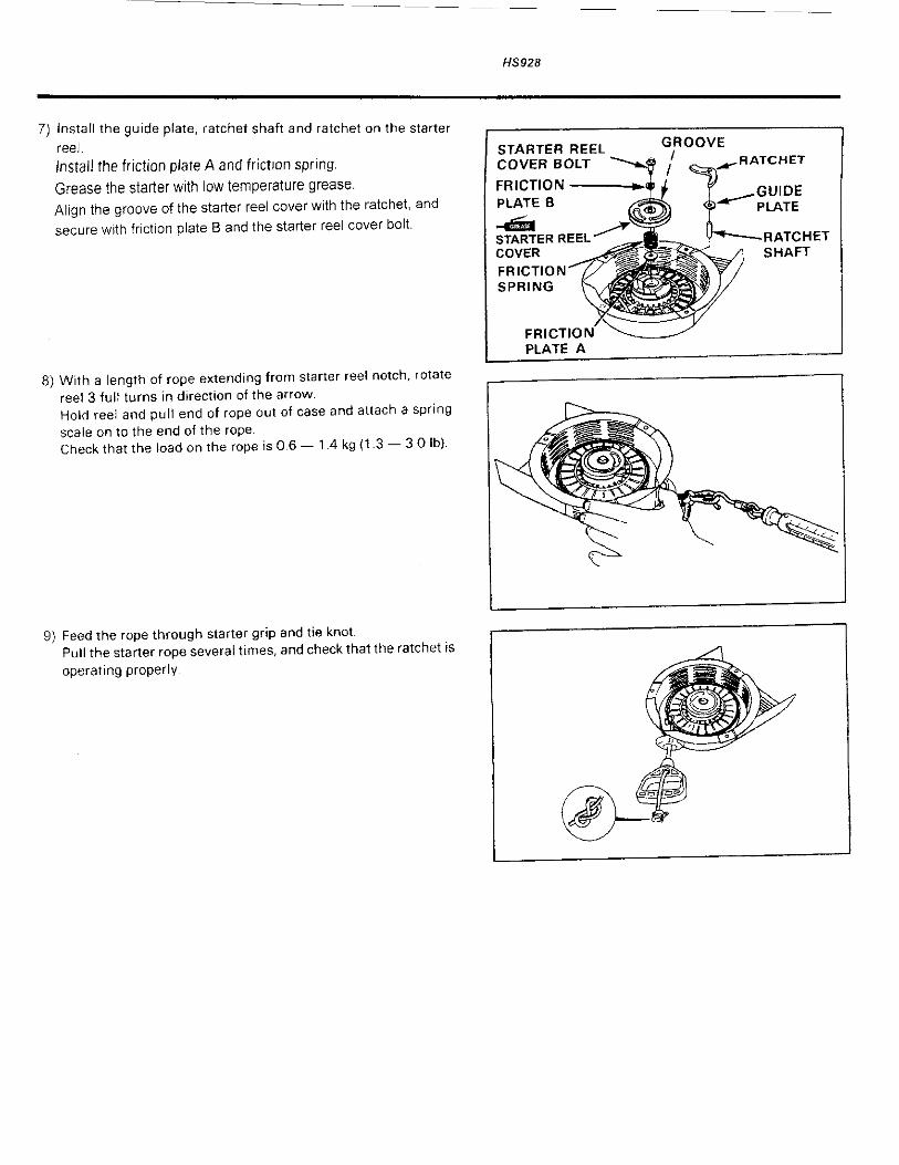
7) Install the guide plate, ratchet shaft and ratchet on the starter
reel. Install the friction plate A and friction spnng. Grease the starter with low temperature grease. Align the groove of the starter reel cover with the ratchet, and
secure with friction plate B and the starter reel cover bolt.
8) With a length of rope extendmg from starter reel notch, rotate reel 3 full turns in dtrection of the arrow. Hold reel and pull end of rope out of case and attach a spring scale on to the end of the rope. Check that the load on the rope is 0.6- 1.4 kg (1.3- 3 0 lb)
9) Feed the rope through starter grip and tie knot. Pull the starter rope several times, and check that the ratchet is
operating properly.
HS928
STARTER REEL COVER BOLT
FRICTION • PLATE B --STARTER REEL COVER FRICTION SPRING
FRICTIO PLATE A
GROOVE I .,.___......-RATCHET

-------
HONDA HSS2S
MUFFlER a. DISASSEMBLY /REASSEMBLY
B mm FLANGE NUT (2)
24 N m (2.4 kg-m. 17 lt-lb)
'"" i
\ ,/ 0
.
-''
)~ \___\
EXHAUST PIPE GASKET
( Do not reuse.
\ '
LEFT MUFFlER PROTECTOR
MUFFLER -----·--------, REASSEMBlY: Install after removing the carbon deposits from the muffler using a plastic hammer.
MUFFLER
B mm FLANGE NUT (2)
[ 24 N.m (2.4 kg-m. 17 ft-lb)
---------
HS928
MUFFLER ASSEMBLY
/ip. - "'-'~' 't ~ 1/-, '/lit·---=-- .) -.....____
(.·I ~-/ill_ ,__J_ ,-_ ·.-- it;;:! 1\'----- . ---0; ~~- (1 ~./ \ e--ll "llil(c' -·r-/l.~ \)!}; /
, _:~ r-)
5 x Bmm PAN SCREW (2)
( RIGHT MUFFLER PROTECTOR
MUFFLER GASKET
Do not reuse.
EXHAUST PIPE
REASSEMBLY:
---
B mm FLANGE-----NUT(3)
Install aher removing the carbon deposits from the exhaust pipe by lightly tapping it with plastic ham- : mer. I
EXHAUST PIPE GASKET
~Do not reuse. :==J
•

•
---~
HS928
FL YWHEEUIGNITION COil 1. FLYWHEEL/IGNITION COIL
FlYWHEEL/IGNITION COIL a. DISASSEMBLY /REASSEMBLY
HONDA HSS2S
• Flywheel/ignition coil disassembly/reassembly can be made w1th the engine installed in the frame. Before disassembly, perlorm the following:
1) Remove the fuel tank/governor (P. 5A). 2) Remove the AC starter switch (P. 18-1 ). 3) Remove the fan cover (P. 6-1 ).
BLACK WIRE
REASSEMBLY: Install the black wire with two clamps to the cylinder barrel.
WOODRUFF KEY (25 x 18)
REASSEMBlY: After reinstalling the flywheel, check to be sure that the woodruff key is still in its slot on the crankshaft.
HIGH TENSION CORD
REASSEMBLY: Check for frayed insulation or other defects.
6 X 25 (2)
TRANSISTORIZED IGNITION COil
jtNSPECTION/ADJUSTMENT: P. 7-2
CODliNG FAN
CAUTION: When disassembling and reassembling. take care not to damage the fan blades. REASSEMBLY: Attach by aligmng the four lugs on the rear side of the fan with the small holes in the flywheel.
FLYWHEEL
DISASSEMBLY: • Do not hit the flywheel with a
hammer. Remove with a commercially avaliable flywheel puller~
• Avoid the magnet section when attaching the puller.
FLYWHEEL PULLER (COMMERCIALLY
AVAILABLE) .
REASSEMBLY: II
• Make certain there are no metal objects stuck to the magnets.
• Adjust the ignition coil air gap after reassembly (P. 7 -2).
16 mm SPECIAl NUT
TORQUE: 113 N-m (11.3 kg-m. 82 ft~lb) DISASSEMBlY/REASSEMBlY: • Apply oil to the thread. • Hold the flywheel by placing
screwdriver into the pulley.
STARTER PULLEY
REASSEMBLY: Attach by aligning the lug {A) on the pulley with the small hole (B) at the center of the flywheel.
~ tBI IAI

HONDA HSS2S
b. INSPECTION • IGNITION COIL NOTE·
• Ignition coil can inspect without removing.
HS928
• If remove the ignition coil, adjust the air gap between ignition coil and flywheel.
• Use the specified tester listed below. - Tester manufactured by Kowa (TH - 5H) -Tester manufactured by Sanwa (SP -lOD) Set the measured range as follows: - Sanwa tester: K 0 range - Kowa tester: R x 100 0 range (When using the Kowa multitester, remember that at\ readings should be multiplied by 1 00).
<Primart side> Measure the resistance of the primary coil by anaching one ohmmeter lead to the ignition coil's primary lead wire while touching the other test lead to the iron core.
I PRIMARY SIDE RESISTANCE I o.7- o.9n ~
<Secondary side>
Measure the resistance of the secondary side of the coil by removing the spark plug cap and holding the test leads to the high tension cord and iron core.
[ SECONDARY SIDE RESISTANCE 6.3- 7.7k!l
NOTE
• A false reading will result if the spark plug cap is not removed.
• SPARK PLUG CAP
Measure the resistance of the spark plug cap by touching one test lead at the wire end of the cap, and the other at the spark plug end.
~esistance 7.5- 12.5k!l
Replace the spark plug cap if the resistance is not within the range specified.
c. ADJUSTMENT
• IGNITION COIL AIR GAP Adjustment is required only when the ignition coil or the flywheel has been removed. 1) Loosen the transistor unit bolts. 2) Insert a long thickness gauge or a piece of paper of the proper
thickness between the ignition coil and the flywheel. Both gaps should be adjusted simultaneously.
3) Push the ignition coil firmly toward the flywheel and tighten the bolts.
[Specifledcle~r;;-nc~3 0.4 ± 0.2 mm (O.o-i6±0-:0oai.;-1··1 NOTE:
Avoid the magnet part of the flywheel when adjusting.
PRIMARY SIDE LEAD WIRE
IRON CORE
SECONDARY SIDE
HIGH TENSION CORD
IGNITION COIL
E7J Q
CAP
TRANSISTORIZED IGNITION COIL
\._
FLYWHEEL

-
CYLINDER HEAD/VALVES 1. CYLINDER HEAD/VALVES
CYLINDER HEAD/VALVES a. DISASSEMBLY /REASSEMBLY
NOTE:
[ Adjust the valve clearance alter reassembly {P. 3-12).
HS928
HONDA HSB2B
• Cylinder head disassembly/reassembly can be made with the engine installed in the frame. Before disassembly, perform the following:
1) Remove the air cleaner (P. 5-1). 2) Drain the fuel and remove the carburetor and fuel tank/governor {P. 5-2 and 5-4).
10 TORQUE: 35 N·m {3.5 kg-m, 25 ft-lb) REMOVAL/INSTALLATION: Loosen and tighten the bolts in a crisscross pattern in 2-3
CYLINDER HEAD COVER BOLT
WASHER
CYLINDER HEAD
REASSEMBLY: Install the gasket on the cylinder head cover as shown.
CYLINDER HEAD COVER ~
CYLINDER HEAD REMOVAL/INSTALLATION: • Before installation, remove any
carbon deposits from the combustion chamber and inspect the valve seats.
• Measure the cylinder compression after reassembly.
DISASSEMBLY/REASSEMBLY: P. 8-2
_...--SHROUD CYLINDER

---·--- ----... ---
HS928
HONDA HSS2S
• CYLINDER HEAD
VALVE ROTATOR (Exhaust valve only)
CAUTION: If the valve rotator is not installed, the exhaust valve may drop into the cylinder when starting the engine.
M
ROCKER ARM PIVOT LOCK NUT (2)
VALVE SPRING RETAINER_t2L__ DISASSEMBLY: Push down and slide the retainer to the side, so the valve stem slips through the hole at the side of the retainer. REASSEMBLY: The exhaust valve retainer has a larger center recess than the iniake valve retainer, so it can accept the valve rotator.
~ CAUTION Do not remove the valve spring retainers while the cylinder head is installed, or the valves will drop into the cylinder.
ROCKER ARM PIVOT BOLT (2)
/10 N•m (1.0 kg-m. 7 ft-lbl/ 124 N•m (2.4 kg-m. 17 ft·lb) I
ROCKER ARM (2)
REASSEMBLY: Before installing, check for wear on the surfaces which contact the pivot bolt, the push rod and the rocker arm pivot.
--------~·---
EXHAUST VALVE
REASSEMBL' Before installation, remove carbon deposits and inspect the valve. INSPECTION: P. 8-3
REASSEMBLY: Do not interchange with the exhaust valve. VALVE HEAO OIMETER IN : 30 mm ( 1 . 18 in) EX: 26 mm (1.02 in) INSPECTION: P. 8-3
CYLINDER HEAD INSPECTION: P. 8-3
PUSH ROO (2) REASSEMBLY: Check both ends for wear and check the rod for straightness. Be sure the rod ends are firmly seated in the lifters.

b. INSPECTION • VALVE FACE/STEM O.D. Inspect each valve face for pitting or wear irregulaties. Inspect each valve for face irregularities, bending or abnormal stem wear. Replace the valve if necessary. Measure and record each valve stem O.D
I
~ STANDARD
IN 6.59 mm 10.259 in)
EX i 6.55 mm 10.258 1n)
• VALVE GUIDE I. D.
NOTE
SERVICE LIMIT
6.44 mm 10.254 in)
640 mm 10.;152_1'1) _
• Ream the valve guides to remove any carbon deposits before measuring
Measure and record each valve guide 1.0.
~ STANDARD SERVICE LIMIT
IN 6.60 mm 10.260 1n) 6.66 mm 10.262 in)
EX 6.60 mm 10.260 in) 6.66 mm 10.262 in)
Replace the guides if they are over the service limit.
• STEAM-TO-GUIDE CLEARANCE Subtract each valve stem 0.0. from the corresponding guide 1.0. to obtain the stem-to-guide clearance
~ STANDARD SERVICE LIMIT
IN 0.01 0.037 mm
10.0004 - 0.0015 in) 0.1 0 mm (0.004 in)
EX 0.05 0077 mm
10 0020- 0.0030 in) 0.12 mm (0.005 in)
lf the stem-to-guide clearance exceeds the service limit. determine if the new guide with standard dimensionS would bring the clearance within tolerance. If so, replace any guide as necessary and ream to fit. If the stem-to-guide clearance exceeds the service limit with new guides, replace the valves as well.
NOTE:
• Recondition the valve seats whenever the valve guides are replaced.
• VALVE SPRING FREE PLAY Measure the free length of the valve springs.
~ STANDARD SERVICE LIMIT
IN 39.0 mm 11.54 in) 37.5 mm 11.48 in)
EX 39.0 mm 11.54 in) 37 5 mm 11.48 in)
Replace the springs if they are shorter 1han the service limit.
• VALVE SEAT WIDTH Measure the valve seat width
~ STANDARD
IN 0.8 mm 10.03 in)
EX 0.8 mm (0.03 in)
SERVICE LIMIT
2.0 mm 10.08 in)
2.0 mm (0.08 in) ·-
If the valve seat width is under the standard. or over the service 11mit, recondition the valve seat (P. 8-6).
HS928
VALVE FACE
HONDA HSB2S
«: 0.8 mm (0.03 in)

HS928
HONDA HSB2B
• CYLINDER HEAD
Remove carbon deposits from the combustion chamber. Clean off any gasket material from the cylinder head surface. Check the spark plug hole and valve areas for cracks. Check the cylinder head for warpage with a straight edge and a feeler gauge.
Service limit 0.10 mm (0.004 in)
FEELER GAUGE

c. VALVE GUIDE REPLACEMENT
1) Chill the replacement valve guides in the freezer section of a refrigerator for about an hour
2) Use a hot plate or oven to heat the cylinder head evenly to
150'C i300'F) Check the temperature with a temperature indicating stick (available at welding supply stores) or equivalent.
To avoid burns, use heavy gloves when handling the heated
cylinder head. ·------------ ·--·-----
CAUTION:
• Do not use a torch to heat the cylinder head; warpage of the cylinder head may result.
• Do not get the head hotter than 150°C (300°F); excessive heat may loosen the valve seats.
3) Remove the heated cylinder head from hot plate and support it with wooden blocks. Drive the valve guides out of the head from the combustion chamber side.
TOOL: VALVE GUIDE DRIVER, 6.6 mm 07942-6570100
CAUTION:
When driving the valve guides out, be careful not to damage the head.
4) Remove the new valve guides from the refrigerator one at a time as needed.
5) Install the new valve guides from the valve spring side of the cylinder head. Drive each valve guide to the specified height (measured from the top of the valve guide to the cylinder casting as shown).
6) After installation, inspect the valve guide for damage. Replace the guide if damaged.
IN 3.0 mm (0.12 in)
EX 3.0 mm (0.12 in)
• VALVE GUIDE REAMING
NOTE~·---------~--------~--~~~------, ~ best results, be sure the cylinder head is at room
~-- t~mper~~--~~-fore ream!::~~-e gu_•_d_e_s ________ ~
1) Coat the reamer and valve guide with cutting oil. 2) Rotate the reamer clockwise through the valve gu1de the full
length of the reamer. 3) Continue to rotate the reamer clockwise while removing it from
the valve guide.
TOOL:
HS928
VALVE GUIDE REAMER, 6.6 mm 07984-ZE2000D, OR 07984-ZE2000C
HONDA. HSB2B
Is -;;;OL I VALVE GUIDE DRIVER, 6.6 mm 07942-6570100 ----.....
Is -;;;OL I VALVE GUIDE REAMER, 6.6 mm 07984-ZE2000D, OR 07984-ZE2000C

HS928
HONDA HSB2B
4) Thoroughly clean the cylinder head to remove any cutting residue.
5) Check the valve guide bore; it should be straight, round and centered in the valve guide. Insert the valve and check operation. If the valve does not operate smoothly, the guide may have been bent during installation. Replace the valve guide if it is bent or damaged.
6) Check the valve guide-to-stem clearance (P_ 8-3).
d. VALVE SEAT RECONDITIONING
1) Thoroughly clean the combustion chamber and valve seats to remove carbon deposits. Apply a light coat of Prussian Blue or erasable felt-tipped marker ink to the valve faces.
2) Insert the valves, and then lift them and snap them closed against their seats several times. Be sure the valve does not rotate on the seat. The transferred marking compound will show any area of the seat that is not concentric.
NOTE:
• Follow the instructions of the valve seat cutter manufacturer.
3) Using a 45° cutter, remove enough material to produce a smooth and concentric seat. Turn the cutter clockwise, never counterclockwise. Continue to turn the cutter as you lift it from the valve seat.
@ @
~ ~ 0 X
;~~'" ..
Is ~OL I SOLID PILOT BARS · 6.60 mm ona1-P02010A
6.62 mm ona1-P00202A 6.65 mm 07781-P02030A T·WRENCH, #505 ona2-P01010A T·WRENCH ADAP10R, #503-1 07782-POl 020A ACCESSORY PACKAGE, #246 ona2-Po1 030A VALVE SEAT CUTTERS
~ #114 ~~60' 30'
#128 45'
07780-?01 020A
07780-POl 01 OB

4) Use the 30° - 32° and 60° cutters to narrow and adJust the valve seat so that it contacts the middle of the valve face. The 30°- 32° cutter removes material from the top edge. The 60° cutter removes material from the bottom edge. Be sure that the Width of the finished valve seat is within specification.
• VALVE SEAT WIDTH
STANDARD SERVICE LIMIT
0.8 mm (0 03 in) 2.0 mm (0.08 in)
5) Make a light pass with 45° cutter to remove any possible burrs at the edges of the seat.
6) After resurfacing the seats, inspect for even valve seating. Apply Prussian Blue compound or erasable felt-tipped marker ink to the valve faces. Insert the valves, and then lift them and snap them closed against their seats several times. Be sure the valve does not rotate on the seat The seating surface, as shown by the transferred marking compound, should have good contact all the way around.
7) Lap the valves into their seats, using a hand valve tapper and lapping compound (commercially available).
CAUTION:
To avoid severe engine damage, be sure to remove all lapping compound from the engine before reassembly. 1
NOTE ~ --------------------·
Check valve clearance after reassembly.
HS928
HONDA HSB2B
CONTACT TOO HIGH
~~ CONTACT TOO LOW
'T·~
O.Smm (0.03 in)
]';VALVE LAPPER

---------
HONDA HSB2B
HS928
------
CYLINDER/CRANKCASE I 1. CYLINDER/CRANKCASE I CYLINDER/CRANKCASE a. DISASSEMBLY /REASSEMBLY
OIL FILLER CAP/ -------. DIPSTICK
8 X 36 (7)
6206 BALL BEARING
REASSEMBLY: Drive the bearing into the crankshaft cover with the marking facing up, using the special tools.
[s.roaL) DRIVER 07749-0010000
ATIACHMENT, 62 x 68 mm 07746-0010500 PILOT, 30 mm
07746-0040700
....... (0)-. OIL SEAL (30 x 46 x 8)
REASSEMBLY: Be careful not to damage the lip of the oil seal when installing the crankcase cover on the crank· case.
[ 24 N-m (2.4 kg-m, 17 ft-lb)
•

•
PISTON
DISASSEMBLY, INSPECTION: P 10-1 REASSEMBLY: Install so that the triangular mark on the piston head points downwards (push rod side). ~ =
0
TRIANGULAR MARK
-«MI
HS928
HONDA HSB2B
~ VALVE LIFTER (2)
DISASSEMBLY: Tilt the engine forward to prevent the lifters from falling out until the
i camshaft is installed.
I OIL SEAL 130 X 46 X 8)
~~~~~
OIL DRAIN BOLT _ .. ----23 N-m (2.3 kg-m, 17 ft-lb)
CONNECTING ROD BDLT(2)
j24 N-m (2.4 kg-m, 17 ft-lb) j
CONNECTING ROD CAP
REASSEMBLY: Install the connecting rod cap as the dip part facing crankcase cover side.
CRANKSHAFT
REASSEMBLY: • Install by pressing in firmly until
contact is made with the bearing surface.
• Take care not to damage the oil seal.
• Take care not to damage the gear on the governor weight. Rotate the shait while pushing it in
6206 BALL BEARING
I REASSEMBLY: I p 10-3
~j~
MECHANICAL DECOMPRESSOR
REASSEMBLY: Before installing, inspect for worn and weakened springs and check that the decompressor weight is moving smoothly.
CAMSHAFT
INSPECTION: P. 10-6 REASSEMBLY: With the crankshaft in place, align the timing punch mark on the cam gear with the punch mark on the crankshaft's cam drive gear.

HONDA HSB2B
GOVERNOR ARM SHAFT
HS928
LOCK PIN
REASSEMBLY: • Install the lock pin immediately
after installing the governor arm shaft. and move the shaft over against the governor slider.
• The lock pin must be installed with the straight side of the pin against the groove in the shaft.
REASSEMBLY:
CAP
REASSEMBLY: Insert firmly into the shaft groove.
GOVERNOR WEIGHT (2)
REASSEMBLY: Check that the GOVERNOR WEIGHT HOLDER weights move free-ly REASSEMBLY:
Check that the gear for wear or damage before installing.
SHAFT GROOVE
WASHER
GOVERNOR SLIDER
REASSEMBLY: Spread the governor weights to install the slider, then check to be sure the slider moves smoothly.
WASHER
GOVERNOR WEIGHT PIN (2)
•

•
HS928
PISTON/CRANKSHAFT /CAMSHAFT
1. PISTON 2. CRANKSHAFT L
PISTON a. DISASSEMBLY /REASSEMBLY
PISTON RING
REASSEMBLY: • Install all rings with the marking facing upward. • Be sure that the top and second rings are not
interchanged. • Check that the rings rotate smoothly after installation. • Spece the p1ston ring end gaps 120 degrees apart, and
do not al1gn the gaps with the piston pin bore.
-----:o TOP RING (CHROME PLATED)
~=~==n SECOND RING
PISTON PIN CLIP (2)
REASSEMBLY:
OIL RING (3-PIECE RING)
• Install by setting one end of the clip in the piston groove, holding the other end with long-nosed pliers, and rotating the clip ln.
• Do not align the end gap of the clip with the cut-out in the piston pin bore.
3. CAMSHAFT
CONNECTING ROD
REASSEMBLY: Install the connecting rod with the long end toward the triangle marked side of the piston.
HONDA HSS2B
TOP RING
PISTON

HS928
HONDA HSB2B
b. INSPECTION
• PISTON SKIRT O.D.
Measure and record the piston 0.0. at a point 10 mm (0.4 in) from the bottom of the skirt and 90° to the piston pin bore
STANDARD SERVICE LIMIT
72.74 mm {2.864 in) 72.62 mm {2.859 on)
• PISTON-TO-CYLINDER CLEARANCE
--STANDARD SERVICE LIMIT
0.26-0.307 mm 0.55 mm {0.022 in)
{0.0102- 0.0121 in)
• PISTON RING SIDE CLEARANCE
STANDARD
0 015 - 0.045 mm (0.0006- 0.0018 in)
• PISTON RING END GAP
STANDARD
Top/ 0.2 -0.4mm 2nd/oil (0.01 - 0.02 in)
NOTE:
SERVICE LIMIT
0.15 mm {0.006 in)
SERVICE LIMIT
1.0 mm (004 in)
• Use the top of the piston to position the ring horizontally in the cylinder.
• PISTON PIN O.D.
STANDARD
18.00 mm {0.709 in)
~------
SERVICE LIMIT
17.954 mm {0.707 in)
10 mm (0.4)
MICROMETER
0

HS928
• PISTON PIN BORE I. D.
STANDARD SERVICE LIMIT
18.002 mm (0.7087 in) 18.048 mm (0 7105 in)
o PISTON PIN-TO-PIN BORE CLEARANCE
STANDARD
0.002- 0.014 mm (0.0001 - 0.0006 in)
SERVICE LIMIT
0.08 mm (0 003 in)
o CONNECTING ROO SMALL END I. D.
E STANDARD SERVICE LIMI:c.T ___ _
_ 18 005 mm (0.708•:9-'m'.'>)'____L _ __'1_-:8:::.0-.:7..'m".m~(O':'C.C'.7C.1 c_1 .:c'nc_) __
o CYLINDER BORE I. D.
Measure and record the cylinder LD_ at three levels in both an X andY axis. Take the maximum reading to determine the cylinder wear. -------------.-----------,
SERVICE LIMIT STANDARD
73.00 mm (2.874 in) 73.17 mm (2.881 in)
CRANKSHAFT CRANKSHAFT BEARING (6206)
REASSEMBLY:
1) Coat the inner bearing with oil and press the bearing onto the crankshaft using the special tools.
TOOLS: DRIVER, 40 mm I.D. ATTACHMENT. 30 mm I.D.
07746-0030100
07746-0030300
( s TOOL I DRIVER. 40 mm I.D. 07746-{)0301 00
( s -;-;;OL I
HONDA HSB2B
A IT AC H ME NT, __ _::;,;t.,.o~ 30 mm I. D. 07746-0030300

HS928
HONDA HSB2B
CRANKSHAFT GEAR DISASSEMBLY /REASSEMBLY
DISASSEMBLY Mark a line on the crankshaft, the timing gear, and the governor drive gear. Set the bearing separator (commercially available) on the bottom of the governor drive gear or timing gear. Press out the gears from the crankshaft
REASSEMBLY 1) GOVERNOR DRIVE GEAR
Using the old governor drive gear for reference, mark a line at the same position on the new governor drive gear. Using the special tools, press in the gvernor drive gear, so that its mark lines up with the mark on the crankshaft.
TOOLS: DRIVER, 40mm I. D. ATTACHMENT, 35 mm I. D.
07746-0030100 07746-0030400
2) TIMING GEAR Using the old timing gear for reference, mark a line at the same position on the new timing gear. Using the special tools, press in the timing gear, so that its mark lines up with the mark on the crankshaft.
TOOLS: DRIVER. 40 mm I. D. ATTACHMENT, 30 mm I.D.
a. INSPECTION
STANDARD
0.1-0.7mm (0.004- 0.028 in)
07746-0030100 07746-0030300
SERVICE LIMIT
1.1 mm {0.04 in)
BEARING SEPERATOR (COMMERCIALLY
AVAILABLE)
Is ;-;;OL I DRIVER, 40 mm I. D. 07746-0030100
Is ;-;;OL I ATTACHMENT. 35 mm I.D. 0746·0030400
Is ;-;;OL I DRIVER, 40 mm I. D. 07746-0030100
[ s -;;;OL I ATTACHMENT 30 mm I. D. 07746-0030300

HS928
HONDA t-19828
CAMSHAFT o CAMSHAFT CAM lOBE HEIGHT
~ STANDARD SERVICE LIMIT
IN 31.2 mm (1.23 in) 30.95 mm (1.219 in)
EX 31.1 mm (1.22 in) 30.85 mm (1.215 1n)
o CAMSHAFT 0.0.
STANDARD SERVICE LIMIT
15.984 mm (0.6293 in) 15.920 mm (0.6268 in)
• • CAMSHAFT HOLDER I. D.
STANDARD SERVICE LIMIT
16.00 mm (0.630 in) 16.05 mm (0.632 in(
-----·-

-
CHUTE 1. CHUTE
CHUTE a. DISASSEMBLY /REASSEMBLY
CHUTE UPPER HANDLE
CHUTE HANDLE BUSH
8 mm FLANGE NUT
c
H$928
HONDA HSB28
CHUTE GUIDE COLLAR (2)
REASSEMBLY: Install the chute guide collar between the chute and chute guide as shown.
CHUTE-
COLLAR
d-o----6 X 14 (2)
X 12 (3)
ACCEL PEDAL WASHER {RESINOID)
6 mm CAP NUT(2)
CHUTE SETTING a, ____ PLATE (3)
SPRING PIN
CHUTE SETTING 14 x 28
mm)(4 )
WASHER (3) DISASSEMBLY: Drive the spring pin out using the pin punch.
(COMMERCIALLY AVAILABLE)
PIN PUNCH ~--<-J.~ 5132 "
CHUTE DRIVE GEAR
REASSEMBLY I ADJUSTMENT: P. 11-2.
GEAR STAY
WASHER
c LOWER HANDLE 8 mm PLAIN WASHER (2)
8 mm FLANGE NUT

H$928
HONDA HSB2B
CHUTE GEAR INSTALLATION
Install the chute drive gear to the chute driven gear. Make sure that backlash between the chute drive gear and driven gear is as follows.
BACKLASH: 0.5 - 1.0 mm (0.02- 0.04 in)
CHUTE DRIVE GEAR
0.5-1.0 mm (0.02- 0.04 in)
: AROUND THE CHUTE DRIVE AND DRIVEN GEARS •

HS928
AUGER/AUGER TRANSMISSION HONDA HSB2S
1. AUGER 3. AUGER HOUSING 2. AUGER TRANSMISSION
AUGER SERVICE BULLETIN #8 =>
a. DISASSEMBLY/REASSEMBLY
NOTE:
L Do not r_:y_~~~~~~-~eft a~~right au~e~- ---··-·------- _________________ __j
SHEAR BOLT. NUT
REASSEMBLY: The shear bolt is a step bolt. Note its direelion when assembling the auger.
NUT oiQ).
SHAFT_::{ )
BLOWER ~
SHEAR BOLT-------i
'""~ AUGER TRANSMISSION
DISASSEMBLY /REASSEMBLY: P. 1 2·2
RIGHT AUGER
8mm WHEEL PIN {2)
NUT {2)
WASHER{2)
CO TIER PIN {2)
1,..;/'1---BLOWER
SHEAR BOLT
AUGER
REASSEMBLY: Insert the 6 x 16 mm flange bolt from the auger side and tighten the 6 mm NUT. (There are two holes at the auger side. Insert the 6 x 16 mm flange bolt through either
of the two holes.
AUGER SHAFT
8 mm WHEEL PIN
6 X 12 {6)
{23 X 8.3 X 3.2) {2)
6 X 16 SHEAR BOLT
! SHEAR BOLT BOSS
AUGER
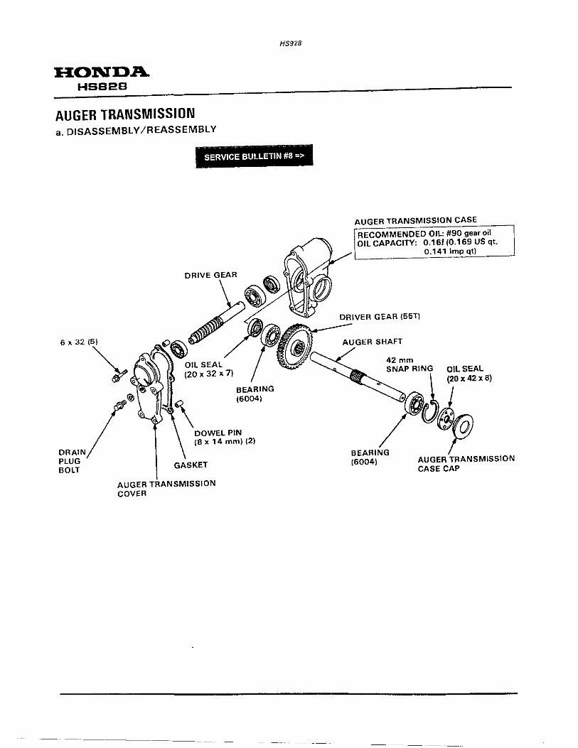
HONDA HSB2B
AUGER TRANSMISSION a. DISASSEMBLY /REASSEMBLY
HS928
~ ~ .
DRAIN PLUG BOLT
SERVICE BULLETIN #8 =>
DOWEL PIN {8 x 14 mm) {2)
GASKET
AUGER TRANSMISSION COVER
AUGER TRANSMISSION CASE
RECOMMENDED OIL: #90 gear oil OILCAPACITY: 0.161(0.169USqt,
0.141 lmpqt)
DRIVER GEAR {55T)
AUGER SHAFT
42mm SNAP RING OIL SEAL
~1~~ .. , BEARING ~ {6004) AUGER TRANSMISSION
CASE CAP

AUGER HOUSING a. OISASSE MBLY/REASSEM
1) Remove th BL Y 2) Remove th: ;uger {P. 1 2~ 1 ).
lnstallati . ~ute (P. 11-1 ). on IS In th 8 order of removal.
SERVICE BULLETIN #19 =>
HS928
CHUTE
CHUTE SETT I ~""' ·-~~~/""' ' . ..
8mm PLAIN WASHER (2)
.I UGER HOUSIN
GUARD G
ADJUSTMENT· p 12-4 .
BEARING (6004 UU)
HONDA HS626
8x16(10)

HONDA HSB2B
- -
HS928
AUGER HOUSING GUARD SERVICE BULLETIN #19 =>
• Adjust auger housing guard ground clearance whenever the guard is removed or replaced.
• Perform this adjustment with the height adjustment pedal in the middle position.
1) Loosen the auger skid plate nuts, and adjust the auger skid to obtain an auger ground clearance as follows.
STANDARD: 4-8 mm (0.16- 0.31 in) FLAT ROAD: 0- 5 mm (0- 0.20 in) ROUGH ROAD: 25 - 30 mm (0.98 - 1.18 in)
2) Loosen the auger housing guard nuts and bolts, and adjust to obtain an auger housing guard ground clearance of 2 -4 mm (0.08- 0.16 in). Tighten the auger housing guard nuts.
3) Readjust the auger skid for snow removal conditions. Tighten the auger skid plate nuts.
AUGER HOUSING GUARD NUT (5)
AUGER HOUSING GUARD I I \
AUGER SKID PLATE NUT (4)
)
(
AUGER SKID PLATE
CLEARANCE BETWEEN AUGER HOUSING GUARD AND GROUND: 2-4 mm (0.08- 0.16 in)
CLEARANCE BETWEEN AUGER AND GROUND: STANDARD: FLAT ROAD: ROUGH ROAD:
4-8 mm (0.16- 0.31 in) 0- 5 mm (0- 0.20 in) 25-30 mm (0.98 -1.18 in)
•

•
HS928
TENSION PULLEY/AUGER BRAKE
1. TENSION PULLEY I AUGER BRAKE
TENSION PULLEY /AUGER BRAKE a. DISASSEMBLY /REASSEMBLY 1) Remove the auger housing (P. 12-3). KEY
(7 X 7 I 33) 'll WI
Pel~
TENSIONER ROLLER RETURN SPRING
AUGER ER RETURN SPRING
SPRING LENGTH
AUGER TENSIONER SPRING
SPRING LENGTH l mm(in)
Tensioner roller spring 75 mm (3.0 in)
Tensioner roller return 50.6 mm (2.0 1n) spring
Auger tensioner spring 82 mm (3.2 1n)
Auger tensioner return 60.9 mm (2.4 1n) spring
TENSION ROLLER
HONDA HSB2B
AUGER PULLEY
NOTE: Be careful not to chan9e the auger pulley for the drive pulley.
DRIVE PULLEY BELT (SA-29)
AUGER PULLEY BELT (LB-35)
I REMOVAL/INSTALLATION: Push the tension roller by hand when I remove or install the belt wh1ch IS slacked. j
(• This spring form is an example.)

HONDA HSS2B
AUGER CLUTCH CABLE
CABLE HOLDER
6 X 12
8 mm FLANGE NUT (2)
COTTER PIN (2)
AUGER BRAKE ARM
DRIVE CLUTCH CABLE
Smm SELF-LOCKING NUT
- ---------------
HS928
AUGER TENSIONER SPRING
TENSIONER ROLLER SPRING
TENSIONER ARM
TENSIONER ARM BUSH (4)
=-----ROLLER BOLT
~b~~--------AUGER TENSIONER ARM
TENSIONER ROLLER RETURN SPRING
AUGER TENSIONER RETURN SPRING
TENSIONER SPRING STAY
0 0
--s x 12 mm FLANGE BOLTS INSTALLATION POSITION
•
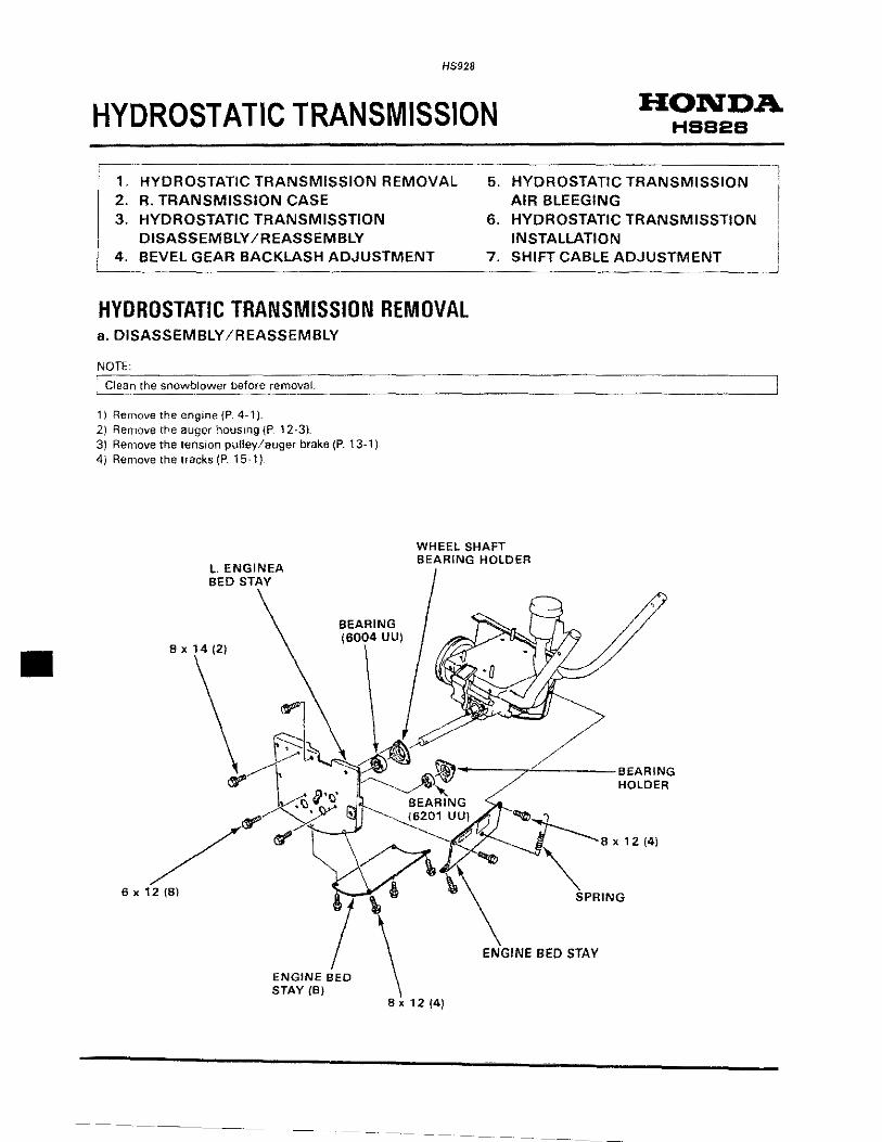
•
H5928
HYDROSTATIC TRANSMISSION
HYDROSTATIC TRANSMISSION REMOVAL a. DISASSEMBLY /REASSEMBLY
NOTE:
HONDA HSB2B
~the snowblower be!?..~~:.'!.':coov.:.::ac::.L ______________________ ____j
1 ) Remove the engine {P. 4-1 ). 2) Remove the auger hous1ng iP 12-3) 3) Remove the tension pulley/auger brake (P. 13~1) 4) Remove the tracks (P. 15· 1}
L. ENGINEA BED STAY
8 X 14 (2)
6x12(8)
SEARING (6004 UU)
WHEEL SHAFT BEARING HOLDER
----7''-----BEARING HOLDER
8 X 12 (4)

HONDA HSB2B
ENGINE BED
12 mm WAVE WASHER
8mm PLAIN WASHER (21
8 mm FLANGE NUT (2)
COLLAR (8 X 12 X 4.7) (2)
6 X 16
WASHER
DRIVEN PULLEY
HYDROSTATIC TRANSMISSION
DISASSEMBLY: P. 14-4 REASSEMBLY: P. 14-7 AIR BLEEDING: P. 14-9
HS928
6 16
TRANSMISSION MOUNTING PLATE
8 mm PlAIN WASHER
8 mm FLANGE
R. TRANSMISSION CASE/ ENGINE BED STAY
DISASSEMBLY /REASSEMBLY: P. 14-3
mm FLANGE NUT
TRANSMISSION FLUID RESERVOIR TANK
RESERVOIR HOSE

HS928
HONDA HS62B
R. TRANSMISSION CASE ,...fMJ COUNTERSHAFT BUSH
a. DISASSEMBLY /REASSEMBLY .--------'_:__:_:_::::.:::.:.:_:_~::_::::_:-_ _______ _
WHEEL SHAFT COLLAR
--·· BEARING (6004 UU)
R. TRANSMISSION CASE
I 5 ;;OL I BEARING REMOVER, 12mm 07936-166010A REMOVER WEIGHT 07936-371020A
or 07936-3710200 OR
BEARING REMOVER, 12mm 07936-1660100 REMOVER WEIGHT 07936-371020A
or 07936-3710200
WASHER ........ WHEEL SHAFT FINAL SHAFT DRIVEN GEAR BUSH
WHEELSHAFT ~ '1 ...tMif0 " , 9ii'""'on~""l::,._-'
WASHER
6mmNUT(6)
-+HI COUNTERSHAFT DRIVEN GEAR
WASHER
-+Mt COUNTERSHAFT DRIVE GEAR
REASSEMBL V; Install the countershaft drive gear to the countershaft as shown.
'"""T~~ COUNTERS HAFT DRIVE GEAR
BEARING (6002)
CROSS SHAFT BUSH INSTALLATION
0 t 0
"UP" SIDE
0 ~0 CROSS SHAFT BUSH
DUST SEAL

HS92B
:~~~~s HYDROSTATIC TRANSMISSION [ ___ 1_-_~T-RANSMISSION CASE
1. R. TRANSMISSION CASE a. DISASSEMBLY/REASSEMBLY <WHEEL TYPE>
---· WHEEL SHAFT DRIVEN GEAR ...
BEARING (6004 DUI
R.TRANSMISSION CASE
WASHERS
---· ---~ WHEEL SHAFT
~ SPECIAL _./ _./ BOLT (2)
6 ""'
WASHER
--·· DRIVE GEAR
FINAL SHAFT BUSH
WHEEL SHAFT COLLAR
DUST CAP
R. TRANSMISSION CASE/ ENGINE BED STAY
CROSS SHAFT BUSH
rREASSEMBLY: Install the cross shaft bush as
1 shown.
I
I 0 0
"UP"SIDE
6 mm NUT (6) REASSEMBLY: I 0,0 Install the drive gear as its spline facing cross shaft side as shown.
DRIVE GEAR
I CROSS SHAFT
CROSS SHAFT BUSH
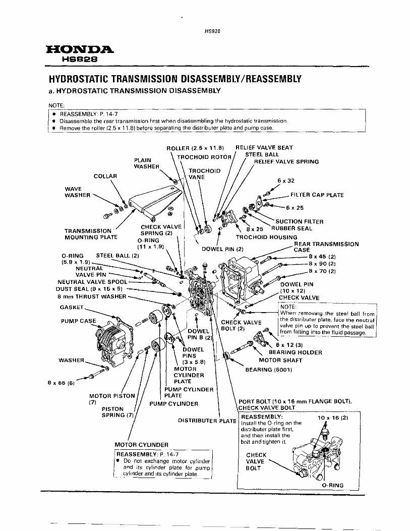
HS92B
HONDA HSB2B
HYDROSTATIC TRANSMISSION DISASSEMBLY /REASSEMBLY a. HYDROSTATIC TRANSMISSION DISASSEMBlY
NOTE:
o REASSEMBLY· P. 14· 7 • Disassemble the rear transmission first when disassembling the hydrostatic transmission • Remove the roller (2.5 x 11.8} before separating the distributer plate and pump case. -- --~~---~--~-
ROLLER (2.5 X 11.8) RELIEF VALVE SEAT STEEL BALL
COLLAR
WAVE \
WASHER~
~~
TRANSMISSION MOUNTING PLATE
CHECK VALVE SPRING (2) I
D-RING .
RELIEF VALVE SPRING
6 X 32
/
~ ~~E:,::,~~ <> \ 8 x 25 RUBBER SEAL
! TROCHOID HOUSING REAR TRANSMISSION (11 X 1.9) DOWEL PIN (2) CASE
0-RING (5.8 X 1.9)
NEUTRAL VALVE PIN
_.--'<"!::-:Cb----- 8 X 45 (2) A-----~ X 90 (2)
X 70 (2)
~----~When removing the steel ball from CHJEC:K the distributer plate, face the neutral
valve up to prevent the steel ball
DISTRIBUTER PLATE
MOTOR CYLINDER
REASSEMBlY: P. 14-7 • Do not exchange motor cylinder
and its cylinder plate for pump ~~~1_nder and its cylinder plate. ~
-----------
from into the fluid
MOTOR SHAFT
BEARING (6001 I
PORT BOLT (10 x 16 mm FLANGE BOLT), VALVE BOLT
REASSEMBLY: Install the 0-ring on the distributer plate first, and then install the bolt and tighten it.
CHECK VALVE BOLT

HS928
b. REAR TRANSMISSION CASE DISASSEMBLY /REASSEMBLY
NOTE
~~~~~-~;r-;~-~ be removed without removing the hydrostatic transmission.
6 X 12
TRANSMISSION RELEASE LEVER
8 x45(2)
BEARING (6002)
,., m'"'"'"'"" ~" BEVEL CROSS SHAFT GEAR
BEVEL GEARCOLLAR
BEVEL GEAR SHIM
Backlash adjusting shim: A: 1.3 mm (0.051 in) B: 1 .4 mm (0.055 in) C: 1 .5 mm (0.059 in) D; 1.6 mm (0.063 in) E: 1. 7 mm (0.067 in) F: 1 .8 mm (0.071 in)
ADJUSTMENT: P. 14·9
BEARING (6904)
15 mm WASHER
OIL SEAL. HOLDER
HONDA HSB2B
8 X 90 (2)
6 X 16
OIL SEAL (1 5 X 28 X 7)

HS928
HONDA. HSB2B
c. PUMP CASE DISASSEMBlY/REASSEMBlY
CLUTCH ARM
30mm SNAP RING
8 X 65 (6)
SPRING PIN CONTROL BUSH B
BEARING (6003)
OIL SEAL(17 x 30 x 6)
SEALING WASHER (9 X 16 X 1.5) (6)
THRUST NEEDLE BEARING
I REASSEMBLY: P. 14-7
CONTROL BOWL CLIP
CONTROL BOWL RING
PUMP CONTROL BOWL
PUMP SHAFT
BEARING PLATE
I REASSEMBLY: P. 14-7
THRUST BALL BEARING
I REASSEMBLY: p 14-7 J

d. HYDROSTATIC TRANSMISSION REASSEMBLY
HS928
1) Install the pump control bowl in the pump case in the reverse
order of disassembly.
2) Install the needle bearing plate (thin), needle bearing, needle
bearing plate (thick), pump shaft and cylinder assembly.
NOTE·
[-[)~- no·t· ex. change the pump cylinder and. its cylinder plate for !
~~oto~ ~_y_ltnder and its cylmder plate. ______________ j
3) Install two dowel pins B (5 x 8 mm) and a new gasket on the
distributer plate. Install the cylinder plate and cylinder. Hang the thrust ball bearing plate (thick) and thrust ball bearing on the motor shaft. Install the thrust ball bearing plate (thin) in the pump case as
shown. Hold the cylinder in the pump case with your fingers, and install it on the distributer plate.
NOTE
'~tall the--thrust ball bearing plate (thick) on the ~~ylinder I
side. \ • Installation of the port bolt (1. 0 x 16 mm) and check valve j
bolt P. 14-4. • Install the cylinder plate w1th the crescent shaped part
facing upward.
4) Install the six 8 x 65 mm flange bolts and tighten them.
NOTE
Make sure that pump shaft and motor shaft rotate smoothly after reassembly.
HONDA HSB2B
PUMP CONTROL NEEDLE BEARING NEEDLE BOWL PLATE (THIN) BEARING
NEEDLE BEARING
PUMP CASE
PUMP CASE
PUMP SHAFT
DOWEL PIN B (5 x 8 mm) (2)
CRESCENT DISTRIBUTER SHAPED PLATE PART
THRUST BALL BEARING PLATE (THIN)
8x65(6)
THRUST BALL BEARING
GASKET
MOTOR SHAFT
THRUST BALL BEARING PLATE (THICK)

HS928
HONDA HSB2B
51 Install the roller (2.5 x 11 .8) in the hole of the pump shaft. Install the trochoid rotor, aligning its groove with roller.
6) Install the spring, steel ball, valve seat and trochoid vane in the
trochoid housing. Install the dowel pins in the distributer plate. Install the trochoid housing with the suction filter and filter cap
plate.
7) Make sure that motor shaft rotate smoothly.
8) Reassemble the rear transmission in the reverse order of
disassembly (P. 14-5). 9) Install two dowel pins and a new gasket {P. 14-5).
Tighten each bolt and install the transmission release lever.
ROLLER (2.5 X 11 .8)
HOLE
STEEL BALL
MOTOR SHAFT
8 X 45 (2)
GROOVE
PUMP SHAFT

HS928
BEVEL GEAR BACKLASH ADJUSTMENT 1) Make a gauge out of cardboard to adjust the bevel gear
backlash as shown.
NOTE·
Adjust bevel gear backlash after reassembling the hydrostatic transmission. Fill the hydrostatic transmission with hydrostatic transmission· fluid after adjusting the bevel gear backlash.
2) Install the neutral valve spool in the distributer plate and push it in fully by hand. Make sure that the cross shaft rotates smoothly If the cross shaft does not rotate smoothly, replace the bevel gear shim with the next thinner size and check again (P. 14-5).
3) Install the gauge made in step 1) with a 6 mm bolt as shown. 4) Attach the scale to the end of the gauge and measure the bevel
gear backlash, moving the cross shaft. Bevel gear backlash should be within 1 mm (0.04 in). If bevel gear backlash is over 1 mm (0.04 in), replace the bevel gear shim with the next thicker size and check again (P. 14-5).
HYDROSTATIC TRANSMISSION AIR BLEEDING 1) Remove the drain plug bolt and washer from the hydrostatic
transmission. Place the hydrostatic transmission with the hole of the drain plug bolt facing upward.
2) Fill the reservoir tank up with hydrostatic transmission fluid until fluid flows out of the plug bolt hole. Install the washer and drain plug bolt. Add fluid as specified (P. 3-3). and install the diaphragm and cap on the reservoir tank.
---------
HONDA HSB2B
¢ 4 mm (0.2 in) HOLE
c 100 mm (3.9 in)
l NEUTRAL VALVE SPOOL
6 mm BOLT
DRAIN PLUG BOLT
~SHER
--~--

HONDA HBB2B
3) Push the neutral valve spool by transmission release lever.
4) WA transmission types
HS928
Install the drive gear (PIN 23421-767-CSO) on the cross shaft as shown, then rotate the cross shaft 10 turns in the direction shown by the arrow.
TA transmission types Install the drive pulley on the cross shaft as shown and rotate the drive pulley 10 turns to the arrow direction.
5) Pull the neutral v81ve spool out and install the driven pulley on the pump shaft. Push the clutch arm to either the right or left direction by hand until the clutch arm does not move. Rotate the driven pulley 30 turns in the direction shown by the arrow. Make sure that cross shaft is mavin~ when turning the driven pulley.
NOTE:
·Rotate the driven pulley (pump shaft) counterclockwise (arrow
direction).
6) Install the hydrostatic transmission (P. 14~ 11 ), and then start the engine and move the snowblower for a few minutes on an asphalt or concrete~paved road.
NOTE:
• Abnormal sounds indicate insufficient air bleeding (steps 4 and 5). In this case, move the snowblower for five or six minutes.
• Aher moving, check the hydrostatic transmission fluid level and add the fluid if necess<iry. {P. 3~3).
TRANSMISSION RELEASE LEVER
NEUTRAL VALVE SPOOL
{for WA transmission)
CROSS SHAFT
{for TA transmission)
CROSS SHAFT
DRIVEN PULLEY
ClUTCH ARM

HYDROSTATIC TRANSMISSION INSTALLATION
HS928
1) Install the transmission mounting plate on the hydrostatic transmission, using the following parts: - (i) : 8 x 40 mm flange bolt - 0: Collar -G) : Wave washer -CD· Plain washers -CD . 8 mm flange nut
NOTE:
Be careful not to pinch the collar and wave washer
2) Install the hydrostatic transmission on the engine bed, aligning the hole of the transmission mounting plate with the 8 mm stud bolt of the engine bed. Temporarily install the washer and 8 mm flange nut.
3) Insert the cross shaft of the hydrostatic transmission in the drive gear hole of the R transmission case/engine bed stay. Install the R. transmission case/engine bed stay on the engine bed with two 8 x 14 mm flange bolts.
4) Install the wheel shaft bearing holder and 6004 UU bearing on the wheel shaft. Install the bearing holder and 6201 UU bearing on the cross
shaft. Temporarily install the left engine bed stay on the engine bed with three 8 x 14 mm flange bolts. Temporarily install six 6 x 12 mm flange bolts on the cross and wheel shaft bearing holders on the left engine bed stay Make sure that the wheel shaft (A·A' line) does not twist, and tighten the left engine bed stay bolts (8 x 14 mm flange bolts) and cross and wheel shaft bearing holder bolts (6 x 12 mm flange bolts) securely. Make sure that A-A· line and B-8' line are parallel after tighten them. Tighten the 8 mm flange nut in the step 2) securely.
8 mm FLANGE NUT
WASHER
HOLE OF THE TRANSMISSION MOUNTING PLATE
8 X 14 (2)
WHEEL SHAFT
B
A
HONDA HSB2B
TRANSMISSION MOUNTING PLATE
TRANSMISSION
8 mm STUD BOLT
R. TRANSMISSION CASE/ENGINE BED STAY
ENGINE BED
LEFT ENGINE BED STAY
A'

HONDA HSB2B
5) Install the engine bed stay and engine bed stay (B).
HS928
6) Make sure that there is 0.5 - 1.0 mm (0.02 - 0.04 in) free play when moving the tip of the pump shaft by hand. , Make sure that wheel shaft (A-A' line) and cross shaft (B-B line) do not twist and are parallel again.
SHIFT CABLE ADJUSTMENT NOTE:
Install the shift cable with the short metal fitting to the clutch arm side if removing the shift cable both ends.
1) Loosen the lock nut and adjusting nut, and hook the shift cable on the shift cable stay.
2) Install the shift cable on the clutch arm, using the setting pin and 6 mm Jock pin.
8 X 12 (4}
PUMP SHAFT
STAY
8 X 12 (4)
ENGINE BED STAY IBI
CLUTCH ARM
(J):r:2--ID"-"i.i~-- 6 mm
SETIING PIN LOCK PIN

HS928
3) Make sure that shift cable is installed correctly as shown. Shift lever and shift cable installation: (P.16-1 ).
4) Move the shift lever all the way forward against the stop, and check the clearance between the shift lever and the control panel. The clearance should be 4 mm (0.2 in). If adjustment is necessary, loosen the 6 mm nuts, and move the shift lever stop Tighten the 6 mm nuts securely.
5) Adjust the distance between the end of the metal fitting and lock nut to 40 mm (1.6 in).
6) Move the shift lever to all the way forward against the stop. 7) Hold the shift cable by hand.
Pull the shift cable down, and adjust the shift cable using the adjusting nut (cable holder side), until there is no slack from cable holder to the shift lever. Tighten the lock nut securely
6mm NUTS
HONDA HSBi2B
SHIFT CABLE INSTALLATION HOLE
FORWARD DIRECTION
CONTROL PANEL
4 mm (0.2 in)
SHIFT LEVER FORWARD DIRECTION
NO SLACK~
ADJUSTING NUT
LOCK NUT
~-==--_-"-ADJUSTING
LOCK o NUT NUT
40 mm ..... (1.6 ;n)
I
~--CABLE ROUTING

HONDA HSBE!B
1. TRACKS
TRACKS a. DISASSEMBLY /REASSEMBLY
SERVICE BULLETIN #13=>
10 mm FLANGE NUT(2)
ADJUSTMENT: P. 3-4
TRACK SPROCKET-------------4~C~r.i COLLAR
BEARING HOLDER
BEARING (6004 UU)
TRACK SPROCKET COLLAR
HS928
DUST SEAL (20 X 34 X 7.5)
COLLAR
TRACKS
COLLAR
HEIGHT ADJUSTING PEDAL
ROLLER
---:!2 mm PLAIN WASHER(2)
TRACK
•

HS928
TRACKS/WHEELS HONDA HS624·HSB2B
,------------1. WHEELS
-----------------------
1. WHEELS a. DISASSEMBLY/REASSEMBLY
GASKET
REASSEMBLY: 6 mm Check the gasket for damage. PIN
INSTALLATIONJ. lnftale to 59kPa (0.6kg/cm2 , 8.5 psi)
WHEElS
I REASSEMBlY,"- -~ Check the wheel bead
1 seat and flanges. j
AIR VAlVE

•
HS928
WHEEL SHAFT PIN INSTALLATION 1) Install the wheel shaft pin on the wheel shaft with its head
facing outside as shown.
2} Instal! the cotter pin on the wheel shaft pin and bend the cotter pin until its tip ·,s within the wheel shaft pin 0.0.
CO ITER PIN
WHEEL SHAFT PIN
COLLAR
HONDA HSS2B
COLLAR
WHEEL SHAFT
WHEEL rHAFT PIN 0.0.
~n ~
COITER PIN
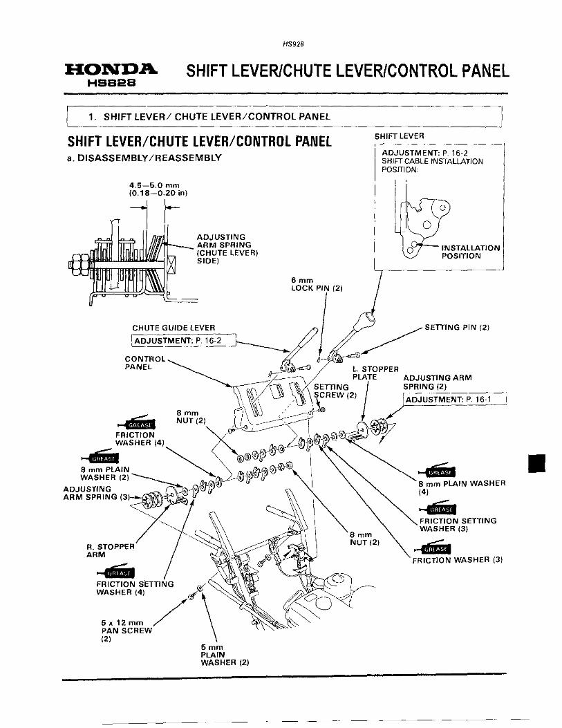
HS928
HONDA SHIFT LEVER/CHUTE LEVER/CONTROL PANEL HSB2B
1. SHIFT lEVER/ CHUTE lEVER/CONTROl PANEl
SHIFT LEVER/CHUTE LEVER/CONTROL PANEL a. DISASSEMBLY /REASSEMBLY
4.5-5.0 mm (0. 18-0.20 in)
ADJUSTING <m--. ARM SPRING
(CHUTE LEVER) SIDE)
6mm LOCK PIN (2)
SHIFT LEVER
ADJUSTMENT: P. 16·2 SHIFT CABLE INSTALLATION POSITION:
0
0
(o
INSTALLATION POSITION
CONTROL #-~ , PANEL ~ ~ l. STOPPER
~~~ PLATE ADJUSTING ARM
rl------J\(11 \\/ SETTING SPRING (2)
~X \Jl\.· \) SCREW 121 ) ADJUSTMENT: P 16·1
Bmm ~~-....4MI NUT(21~ •, '-~ ~, FRICTION ~ , ~~~"~PJ ~tJ! WASHER (4) @-@ /f..
_.., ~ < ®®~~ I 8 mm PLAIN ~ ~~~ I WASHER (2) ~ @"'(I]} (1]}/1~ if
~:U."l::::~, ,~f)'~
R. STOPPER ARM ---· / FRICTION SETTING ~ '
WASHER (4) ~ \
5x12mm / PAN SCREW (2)
5mm PLAIN WASHER (2)
Bmm NUT {2)
---B mm PLAIN WASHER (4)
~--FRICTION WASHER (3)
----·-----
•

•
SHIFT LEVER LOAD ADJUSTMENT Shift lever load adjustment is made by screwing the two 8 mm nuts in or out.
1) Move th shift lever to the "FORWARD" position fully. 2) Screw the 8 mm nut in so the shift lever load is within the
following specification.
SHIFT lEVER toAD: 3.0- 5.0 kg (6.6- 11.0 lbJ
After adjustment tighten the 8 mm nut securely.
NOTE·
• The shift lever may move if the shift lever load Is under the specification. Measure the load as shown in the illustration.
• Adjust the shift cable after this adjustment (P.14-12)
CHUTE GUIDE LEVER LOAD ADJUSTMENT Chute guide lever load adjustment is made by screwing the two 8 mm nuts in or out.
1) Move the chute guide lever to the "UP" position. 2) Screw the 8 mm nut in so the chute guide lever load is within
the following specification.
CHUTE GUIDE LEVER LOAD: 6.0- 7.0 kg {13- 15 lb)
After adjustment. tighten the 8 mm nut securely.
NOTE·
• The chute guide lever may move if the chute guide lever load is under the specification. Measure the load as shown in the illustration.
• Adjust the chute guide cble after this adjustment (P.3-5).
HS9Z8
OPERATOR SIDE
8 mm NUT
HONDA. HSB2B
8 mm NUT
30mm {1.2 in)
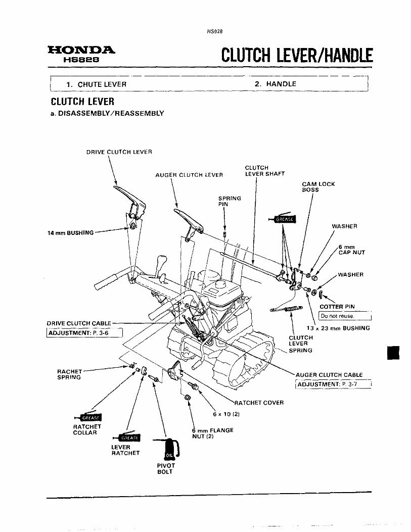
HONDA HSB2B
1. CHUTE LEVER
CLUTCH LEVER a. DISASSEMBLY /REASSEMBLY
DRIVE CLUTCH LEVER
HS928
CLUTCH LEVER/HANDLE 2. HANDLE
CLUTCH LEVER CLUTCH
SHAFT
14 mm BUSHING
DRIVE CLUTCH CABLE ----_':;;;L..,...<::l:J,~~"' I ADJUSTMENT: P. 3-6
RACHET---SPRING
...... .,. RATCHET COLLAR
LEVER RATCHET
PIVOT BOLT
X 10 (2)
...... CAM LOCK BOSS
WASHER
mm CAP NUT
WASHER
COTTER PIN
[ Do not reuse.
13 x 23 mm BUSHING
LEVER SPRING
CLUTCH CABLE
I ADJUSTMENT: p 3· 7
•

HONDA HS724 • HS928
HS928
17. CHUTE LEVER/HANDLE 1. HANDLE - ·r ~~~ --------------- --------·-------··----'
1. HANDLE a. DISASSEMBl V /REASSEMBLY
HANDLE GRIP (2) THROTILELEVER
REASSEMBLY: I Apply adhesive to the. THROTILE LEVER PLATE SPRING SEAT handlebars when installing i
the grips. _ _j 6 mm CAP NUT
ENGINE SWITCH
~
WIRE HARNESS BAND
ENGINE SWITCH WIRE
GROUND CABLE
6 X 12
THROTILE LEVER SPRING
HANDLEBAR
THROTILE CABLE
8 mm FLANGE NUT (4)
FRAME JOINT WASHER(4)

HONDA HSB2B
1. AC STARTER MOTOR
AC STARTER MOTOR a. REMOVAL/INSTALLATION o AC STARTER SWITCH
o AC STARTER MOTOR 1) Remove the fan cover {P.6-1 ).
I
k ~·
8 X 35 (2)
HS928
AC STARTER MOTOR
AC STARTER SWITCH
I DISASSEMBLY /REASSEMBLY: P. 18·2
GROUND CABLE
/
6x8 6 X 12 (3)
AC STARTER MOTOR
Measure staner performance while cranking the engine. If performance is not within service limits, disassemble and inspect as described on page 18-2.
Cranking voltage
Cranking current
Engine cranking speed
Under load
117V AC
Below 13.1A
More than 400 min-1 (rpm)
No load
117V AC

HS928
b. DISASSEMBLY /REASSEMBLY
REDUCTION GEAR
DRIVE GEAR
PINION HOUSING
CASE • WHITE LEAD
STARTER SWITCH
BRUSH 121
INSPECTION: P. 18-3 REASSEMBLY:
HONDA HSB2B
Push in the brushes so they do not interfere with the commutator.
ARMATURE
INSPECTION: P 18-4 REASSEMBLY: Visually inspect the commutator surface for dust, rust or other damage. If necessary, wipe it with a clean lint-free cloth. If rusted
dress with a fine cloth
YOKE
REASSEMBLY:
x30mm SCREW-WASHER (3)
Make sure that there 1s no obstruction on the
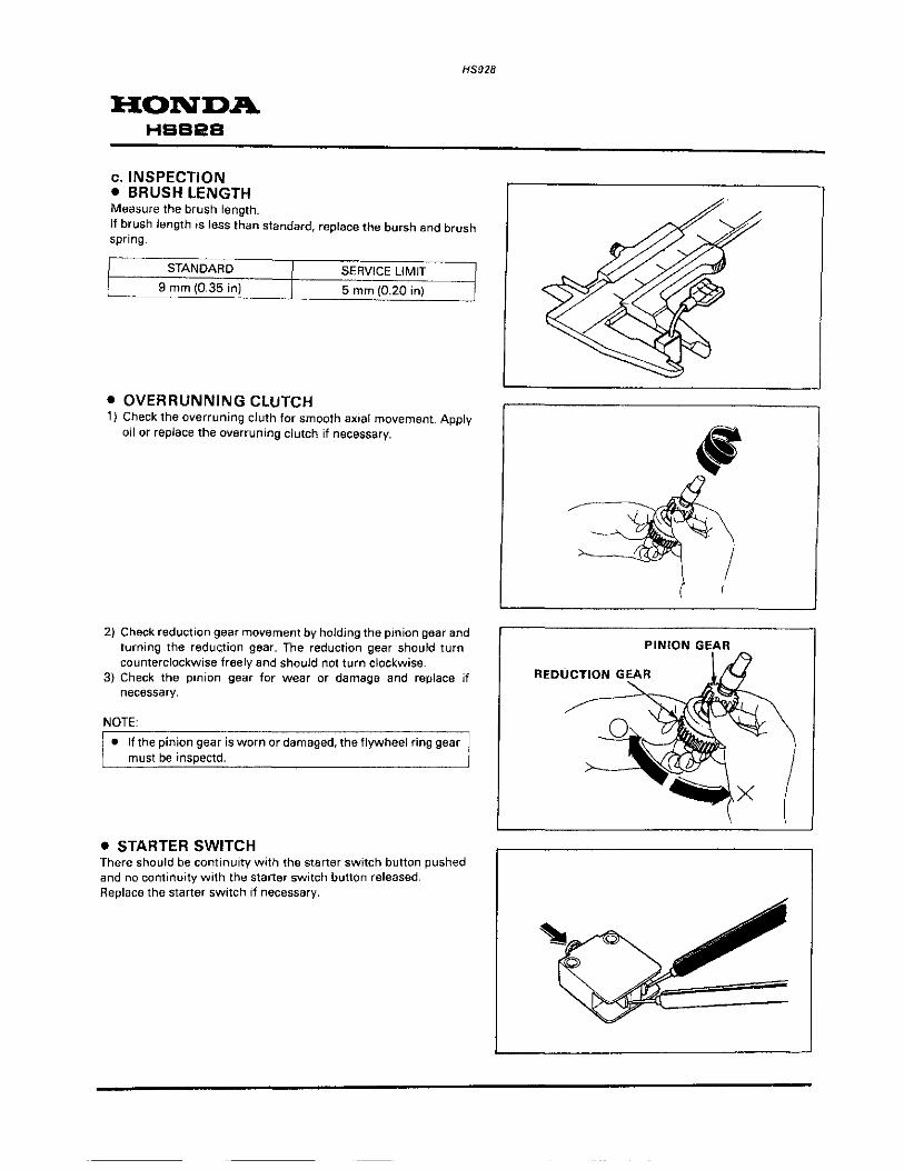
HONDA HBB&B
c. INSPECTION • BRUSH LENGTH Measure the brush length.
HS928
lf brush length is less than standard, replace the bursh and brush spring.
STANDARD SERVICE LIMIT 9 mm (0.35 in) 5 mm (0.20 in)
• OVERRUNNING CLUTCH 1) Check the overruning cluth for smooth axial movement. Apply
oil or replace the overruning clutch if necessary.
2) Check reduction gear movement by holding the pinion gear and turning the reduc.tion gear. The reduction gear should turn counterclockwise freely and should not turn clockwise.
3) Check the pinion gear for wear or damage and replace if necessary.
NOTE:
• If the pinion gear is worn or damaged, the flywheel ring gear must be inspectd.
• STARTER SWITCH There should be continuity with the starter switch button pushed and no continuity with the starter switch button released. Replace the starter switch if necessary.
PINION GEAR

• DIODE PACK
Check for continuity between the terminals.
.. ~. NEGATIVE PROBE ~---i ~ ··---:;:--·· -1 . -2 f-· --
POSITIVE + ~ 0 0 0
PROBE -1 ~ ~ ~ 0
-2 = = -....____ 0
- = ~ ~
--------There should be continuity at the position marked with , and no continuity at the posit1on marked with=.
• ARMATURE • COUNTINUITY CHECK-SEGMENTS Check for continuity between segments. If an open circuit exists between any two segments, replace the armature
• SHORT CIRCUIT TEST-CORE TO COMMUTATOR
Check for continUity between the commutator and armature coil core. If continuity exists, replace the armature.
• SHORT CIRCUIT TEST-SHAFT TO COMMUTATOR
Check for continuity between the commutator and armature shaft. If there is continuity, replace the armature.
HS928
HONDA HSS2S
-1 + -1 CIRCUIT
+
-2 -2
------·--- ----··-·

HONDA HSB2B
• MICA DEPTH Clean the segment with a soft brush if necessary.
H$928
Replace the armature if the mica depth is less than the service limit.
SERVICE LIMIT: 0.3 mm (0.01 in)
•

•
HS928
OPERATION HONDA HSS2S
~·· 1. HST (HYDROSTATIC TRANSMISSION) 2. THROTTLE LEVER INTERLOCKED CHOKE
HST (HYDROSTATIC TRANSMISSION) <Summary>
The HST {hydrostatic transmission) hydrostatically and stagelessly shifts the gear from FORWARD to REVERSE gear and from REVERSE to FORWARD gear. With a simple shift operation, you can select the best speed for various snow clearing conditions .

HONDA HSB2B
<Operating principle>
H$928
The oil pressure pump consists of the control yoke, that changes the tilt angle, and the pump cylinder that contains the seven ptstons.
PUMP CYLINDER
0
PISTON
Engine power is transmitted to the pump shaft through the V-belt, and the pump shah rotates the pump cylinder. As the control yoke angle changes, the pistons in the pump cylinder start reciprocating.
PUMP SHAFT
(VIEWED FROM THE CONTROL YOKE SIDE)

HS928
HONDA HSB2B
The fluid is drawn into the oil pressure pump through the suction port and is discharged through the discharge port by this reciprocating motion of the pistons. The discharged amount of the fluid varies according to the control yoke angle.
SUCTION PORT OF THE OIL PRESSURE PUMP
SUCTION PORT OF THE OIL PRESSURE MOTOR
OIL ,,._-J._PRESSURE
MOTOR
,( I) > -'
~
The discharged fluid is drawn into the oil pressure motor. The oil pressure motor consists of the bearing, which is set at a certain angle, and the motor cylinder which contains the 7 pistons. Getting the pressure of the fluid drawn through the suction port, the pistons are pushed along the motor bearing and it rotates together with the motor cylinder. The motor speed varies according to the amount of fluid drawn through the suction port.
MOTOR CYLINDER BEARING
(VIEWED FROM THE BEARING SIDE)
PISTON

HONDA HSB2B
HS928
The piston moves along the bearing and enters the discharge stroke after it passes the bottom dead center. Fluid is discharged
to the oil pressure pump this time.
BOTTOM DEAD CENTER
TOP DEAD CENTER
Oil flow
<In forward gear>
DISCHARGE PORT OF THE OIL PRESSURE MOTOR
I SUCTION PORT OF THE OIL PRESSURE PUMP
The fluid discharged from the oil pressure pump rotates the oil pressure motor and returns to the oil pressure Pump. The fluid leaked through the gaps in the hydrostatic circuit is compensated with the fluid from the charging pump
OIL PRESSURE PUMP
OIL PRES
CHARGI PUMP
CHECK VALVE
OIL PAN

HS928
HONDA HSB2B
<In reverse gear> When the shift lever is moved to REVERSE, the control yoke tilts to the reverse side and exchanges the suction port and discharge port of the oil pump, resulting in reverse oil flow and reverse motor cylinder rotation.
OIL PRESSURE MOTOR
Shift lever in STOP
CHECK
===~[VALVE
OIL PAN
When the shift lever is moved to the STOP position. the oil pump pistons' reciprocating motion and discharge of fluid stop. The fluid drawn into the charging pump returns through the relief valve to the case.
OIL PUMP
RELIEF LVALVE

HONDA HBB2B
Transmission release lever
HS928
When the oil pressure motor is rotated by outside force with the engine stopped, as when the operator pushes the snowblower, the oil pressure motor operates in the same manner as the oil pressure pump (that is suction and discharge of fluid). With the neutral valve ON, the oil pressure pump and the oil pressure motor are connected with the hydrostatic circuit. As the oil pressure pump does not rotate this time, the hydrostatic circuit closes and locks the tracks or wheels.
NEUTRAL VALVE
When the neutral valve is turned OFF (to move the snowblower by pushing it), the hydrostatic circuit opens and the oil pressure motor starts so that the snowblower can be moved by pushing.
OIL PAN :d:!J

HS928
THROTILE LEVER INTERLOCKED CHOKE The choke for starting the eng·me is interlocked the throttle lever tor convenience. Operating the choke and adjusting the engine r.p.m. can do easily with only one lever.
<Summary> Throttle control linkage includes® control lever,® speed control lever and© choke lever. ®and® are connected with the lever spring which exceeds the load of the governor spring. The throttle cable is connected to® and the governor spring is connected to 0.
@SPEED CONTROL LEVER
HONDA HSB2B
© CHOCK LEVER
0 CONTROL LEVER
LEVER SPRIN
<Operating>
1) Standard engine speed- Maximum speed
Moving the throttle lever from "SLOW" to "FAsr·. pulls® by the throttle cable and operates® by the lever spring at the same time. The governor spring is pulled by® operation and the engine runs at speed.
@SPEED CONTROL LEVER
• Standard engine speed adjustment is made by adjusting screw CD. • Maximum engine speed adjustment is made by adjusting screw 0.
THROTILE CASE
ADJUSTING SCREW(j)

HONDA HSB2B
HS928
2) When moving the throttle lever to "CHOKE",® contacts the adjusting screw® and stops. Lever spring tension moves the speed control lever@, pulling the choke lever© in the direction shown in the illustration. The choke valve of the carburetor is fully closed by the choke rod.
THROTILE LEVER
ADJUSTING SCREW CD
®CONTROL LEVER
AOJUSTING SCREW CD
LEVER SPRING

INDEX AC starter motor Air cleaner Auger
18-1 5-1
disassembly/reassembly ......................................... 12~1 belt ...................................................................... 3-7 housing ............................................................... 12-3 transmission .......................................................... 12-2
Belt stopper ............................................................ 3-11 Bevel gear backlash adjustment . . ........ 14-9 Cable/harness routing ............................................ 2-21 Camshaft ............................................................... 10-6 Carburetor inspection ...•................ . ...•........... disassembly/reassembly ................... .
Chute
3-5 5-2
disassembly/reassembly.............................. 11·1 guide control cable ....... ............................. 3-5
Clutch lever ... . ............................................. 17-1 Crankshaft .............................................................. 10-3 Cylinder head/valves ............................................... 8-1 Cylinder/crankcase ........... ................. 9-1 Dimensional drawing ............................................... 1-3 Drive belt ............................................................... 3-6 Engine oil . . .. ........ ... . . . ... .. ...... ............ ... ... . . ... . .. . . ... ... 3-2 Engine removal/installation ...................................... 4-1 Flywheel/ignition coil .............................................. 7-1 Fuel strainer cap .. . .. . . .. . . .. .. . ... ... ......... .. . . .. . . ... . .. . . .. . . .. 3-4 Fuel tank/fuel strainer ............................................. 3-6 Fuel tank/governor ................................................. 5-4 General safety ......................................................... 2-1 Handle ........................................ , .................. , ...... 17-2 HST (hydrostatic transmission) ................................. 19-1 Hydrostatic transmission air bleeding ........................................................... 14-9 disassembly/reassembly ......................................... 14-4 fuid ........................................................ 3~ installation .......................................................... 14-1 1 removal ..................................................... 14-1
lubrication points .................................................... 2-20 Maintenance schedule . . . ... . . .. . . ... .. .. . .. . . .. . .. .. ... ... . .. .. ... . . .. . 3-1 standards . . . . .. . .. . . .. . .. . . . . . . . .. . .. .. . .. .. .. . . ... . . .. . .. . . . . . .... ... 2-3
Muffler................................................................... 6-4 Piston .................................................................... 10-1 Recoil starter /fan cover .... ... ...... ...... .. . . .. . .. .. . 6-1 Right transmission case ........................................... 14-2 Serial number location .. .... . .. .. . .. ............ .... .... .. . . .... . .. 2-2 Service rules ........................................................... 2-1 Shear bolts ............................................................. 3-4 Shift cable adjustment ........................................... 14~12 Shift level/chute lever/control panel ......................... 16-1 Spark plug .............................................................. 3-3 Special tools ........................................................... 2-6 Specifications ......................................................... 1-1 Tension pulley/auger brake ...................................... 13-1 Throttle lever interlocked choke ................................ 19-7 Throttle/choke cable ............................................... 3·9 Torque values ......................................................... 2-5 Tracks
adjustment ................... ........................................ 3-4 disassembly/reassembly ........................................ 15-1
Troubleshooting .............. ....... .... .......... 2-7 Valve clearance ....................................................... 3~12
HS928
HONDA HSB28