honda cg125 76 91 service manual
TRANSCRIPT
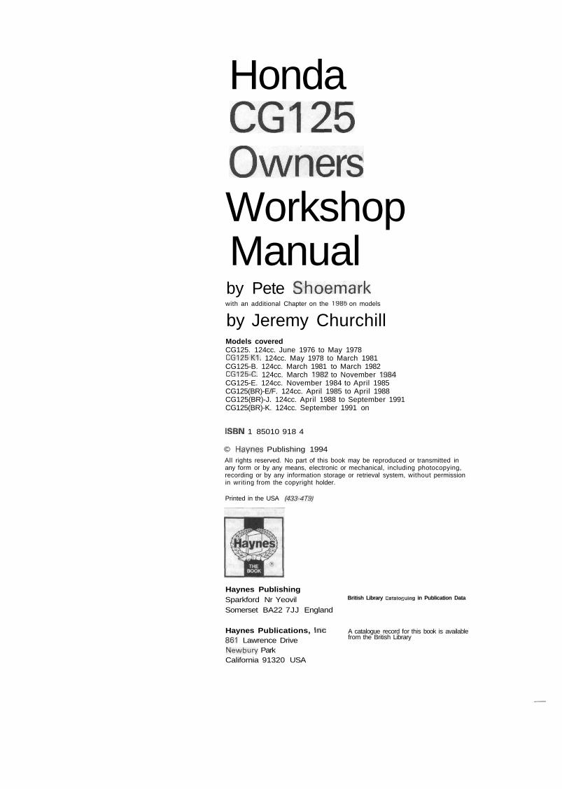
HondaCG125OwnersWorkshopManualby Pete Shoemarkwith an additional Chapter on the 1985 on models
by Jeremy ChurchillModels coveredCG125. 124cc. June 1976 to May 1978CG125K1. 124cc. May 1978 to March 1981CG125-B. 124cc. March 1981 to March 1982CG125-C. 124cc. March 1982 to November 1984CG125-E. 124cc. November 1984 to April 1985CG125(BR)-E/F. 124cc. April 1985 to April 1988CG125(BR)-J. 124cc. April 1988 to September 1991CG125(BR)-K. 124cc. September 1991 on
ISBN 1 85010 918 4
© Haynes Publishing 1994All rights reserved. No part of this book may be reproduced or transmitted inany form or by any means, electronic or mechanical, including photocopying,recording or by any information storage or retrieval system, without permissionin writing from the copyright holder.
Printed in the USA (433-4T9)
Haynes PublishingSparkford Nr YeovilSomerset BA22 7JJ England
Haynes Publications, Inc861 Lawrence DriveNewbury ParkCalifornia 91320 USA
British Library CataloGuing in Publication Data
A catalogue record for this book is availablefrom the British Library
~
AcknowledgementsOur thanks are due to APS Motorcycles of Wells (formerly
Fran Ridewood & Co), Paul Branson Motorcycles of Yeovil, andCSM of Taunton, who supplied the machines featured in thismanual.
We would also like to thank the Avon Rubber Company, whokindly supplied information and technical assistance on tyrefitting; NGK Spark Plugs (UK) Ltd for information on spark plugmaintenance and electrode conditions and Renold Limited foradvice on chain care and renewal.
About this manualThe author of this manual has the conviction that the only
way in which a meaningful and easy to follow text can bewritten is first to do the work himself, under conditions similarto those found in the average household. As a result, the handsseen in the photographs are those of the author. Even themachines are not new: examples that have covered a consider-able mileage were selected so that the conditions encounteredwould be typical of those found by the average owner.
Unless specially mentioned, and therefore consideredessential, Honda service tools have not been used. There isinvariably some alternative means of slackening or removingsome vital component when service tools are not available andrisk of damage has to be avoided at all costs.
Each of the six Chapters is divided into numbered Sections.Within the Sections are numbered paragraphs. In consequence,cross reference throughout this manual is both straightforwardand logical. When a reference is made 'See Section 5.12' itmeans Section 5, paragraph 12 in the same Chapter. If anotherChapter were meant, the text would read 'See Chapter 2,
Section 5.12'. All photographs are captioned with aSection/paragraph number to which they refer and are alwaysrelevant to the Chapter text adjacent.
Figure numbers (usually line illustrations) appear innumerical order, within a given Chapter. Fig. 1.1 therefore refersto the first figure in Chapter 1. Left-hand and right-handdescriptions of the machines and their component parts refer tothe right and left of a given machine when the rider is seatednormally.
Motorcycle manufacturers continually make changes tospecifications and recommendations, and these, when notified,are incorporated into our manuals at the earliest opportunity.
We take great pride in the accuracy of information given inthis manual, but motorcycle manufacturers make alterations anddesign changes during the production run of a particularmotorcycle of which they do not inform us. No liability can beaccepted by the authors or publishers for loss, damage or injurycaused by any errors in, or omissions from, the information given.
Contents
Acknowledgements
About this manual
Introduction to the Honda CG125
Model dimensions and weight
Ordering spare parts
Safety first!
Routine maintenance
Quick glance maintenance adjustments and capacities
Recommended lubricants
Working conditions and tools
Chapter 1 Engine, clutch and gearbox
Chapter 2 Fuel system and lubrication
Chapter 3 Ignition system
Chapter 4 Frame and forks
Chapter 5 Wheels, brakes and tyres
Chapter 6 Electrical system
Chapter 7 The 1985 on models
Wiring diagrams
Conversion factors
Index
Page
2
2
5
5
6
7
8
13
13
/
15
52
60
67
80
93
107
103, 124
125
126
I
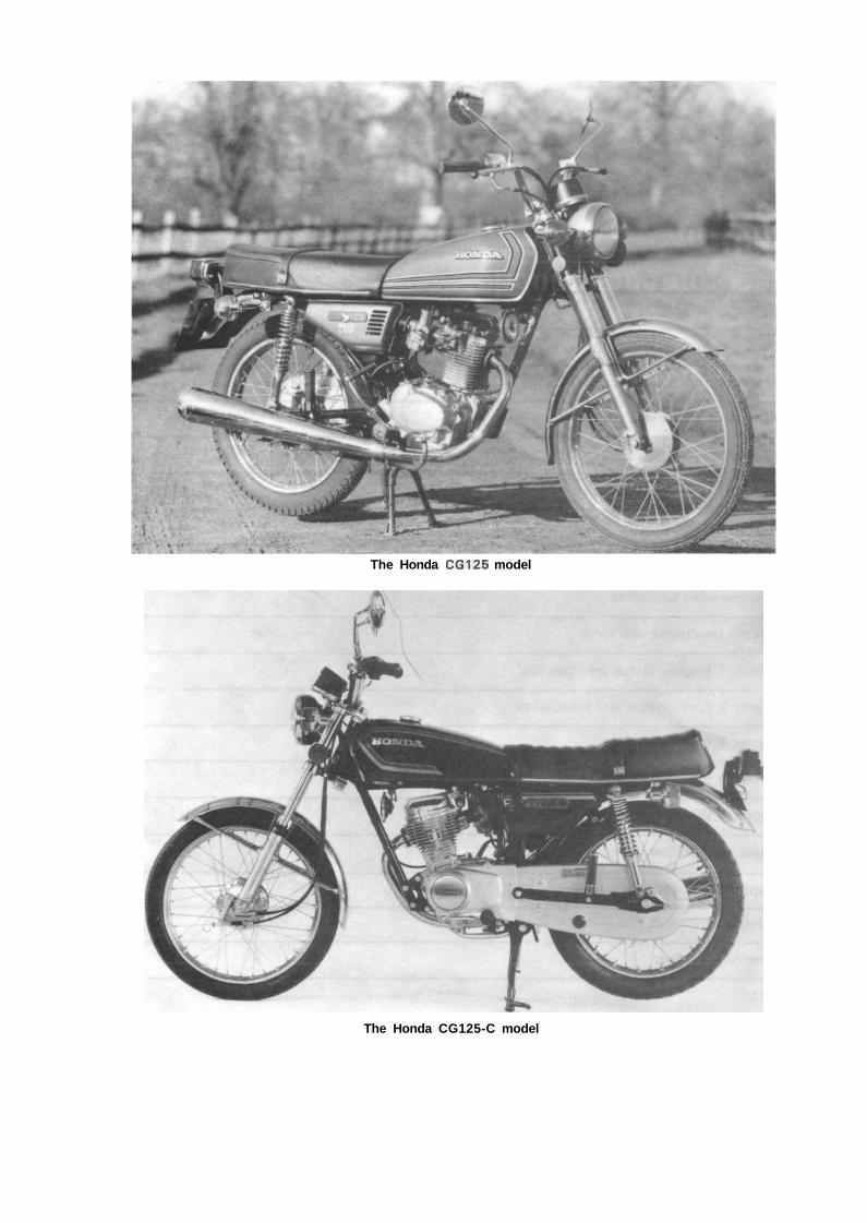
The Honda CG125 model
The Honda CG125-C model
Introduction to the Honda CG125The CG125 model first appeared in the UK in June 1976. It
can be regarded in many ways as a utility version of the popularCB1 25 with which it shares many features. The basic differencebetween the two models is the CG125's use of pushrodoperated overhead valves in place of the more popular overheadcamshaft arrangement. The unit provides surprisingly briskperformance coupled with good fuel economy. The machine ingeneral is functional and sensibly equipped, and does not sufferthe surfeit of gadgetry so often found on its contemporaries. Itsinherent simplicity makes it an ideal learner's or commuter'smount, both in terms of ease of riding and in its ease ofmaintenance. A noteworthy feature is the adoption of a full rearchain enclosure. Although this is by no means a new idea,having appeared and disappeared many times over the yearswith the changing dictates of fashion, it is, nevertheless, aneminently sensible feature, greatly extending chain life.
Despite remaining basically unchanged, the CG125 hasreceived several modifications and has been altered slightly inappearance to keep up with its rivals. Five distinct versions haveappeared, with differences of varying significance, which areidentified (where applicable) in this Manual by their Hondamodel code suffixes. Identification details, as available, aregiven below with the approximate dates of import; note that thelatter need not necessarily coincide with the machine's date ofregistration.
The CG125 model (no identifying suffix) has the framenumbers CG125-1023061 to 1111090. Engine numbers arenot available. Identified by its shrouded, external spring, frontforks, this model Was imported from June 1976 to May 1978.
The CG125K1 model has the frame numbersCG125-1114636 to 1162518. Engine numbers not available.It differed most noticeably from the CG125 model in havingfront forks with internal springs and exposed stanchions, andwas imported from May 1978 to March 1981.
The CG125-B model has the frame numbersCG125-1202755 to 1223689; its engine numbers start atCG125E-1374586. It can be distinguished from the K1 modelonly by its different paintwork and graphics and was importedfrom March 1981 to March 1982.
The CG125-C model has the frame numbersCG125-1272831 to 1286692; its engine numbers start atCG125E-1513928 on. Fitted with revised tail lamp, flashingindicator lamps, handlebar switches and the usual detailchanges to paintwork and graphics. This model is also fittedwith a higher compression engine and the (T)PFC carburettorfor greater fuel economy. Note also that the ignition switch iscombined in a new warning lamp cluster, mounted next to thespeedometer. Imported from March 1982 to November 1984.
The CG125-E model has the frame numberCG 125-1288790 to 1293380 and the engine numbersCG125E-1689761 to 1694851. Identical to the C modelexcept for detail changes to the graphics, this model wasimported from November 1984 to April 1985.
All the aforementioned models are of Japanesemanufacture and are covered in Chapters 1 to 6. Later modelswere manufactured in Brazil and known as the CG125(BR)models; refer to Chapter 7 for further information.
Model dimensions and weightOverall length
Overall width
Overall height
Wheelbase
Seat height
Ground clearance
Dry weight
1840 m m (72.4 in)
735 m m (28.9 in)
1025 mm (40.4 in)
1200 m m (47.2 in)
755 m m (29.7 in)
135 m m (5.3 in)
95 kg (209 Ib)
Ordering spare parts
*
When ordering spare parts for the CG125 models, it isadvisable to deal direct with an official Honda agent, who willbe able to supply many of the items required ex-stock. It isadvisable to get acquainted with the local Honda agent, and torely on his advice when purchasing spares. He is in a betterposition to specify exactly the parts required and to identify therelevant spare part numbers so that there is less chance of thewrong part being supplied by the manufacturer due to a vagueor incomplete description.
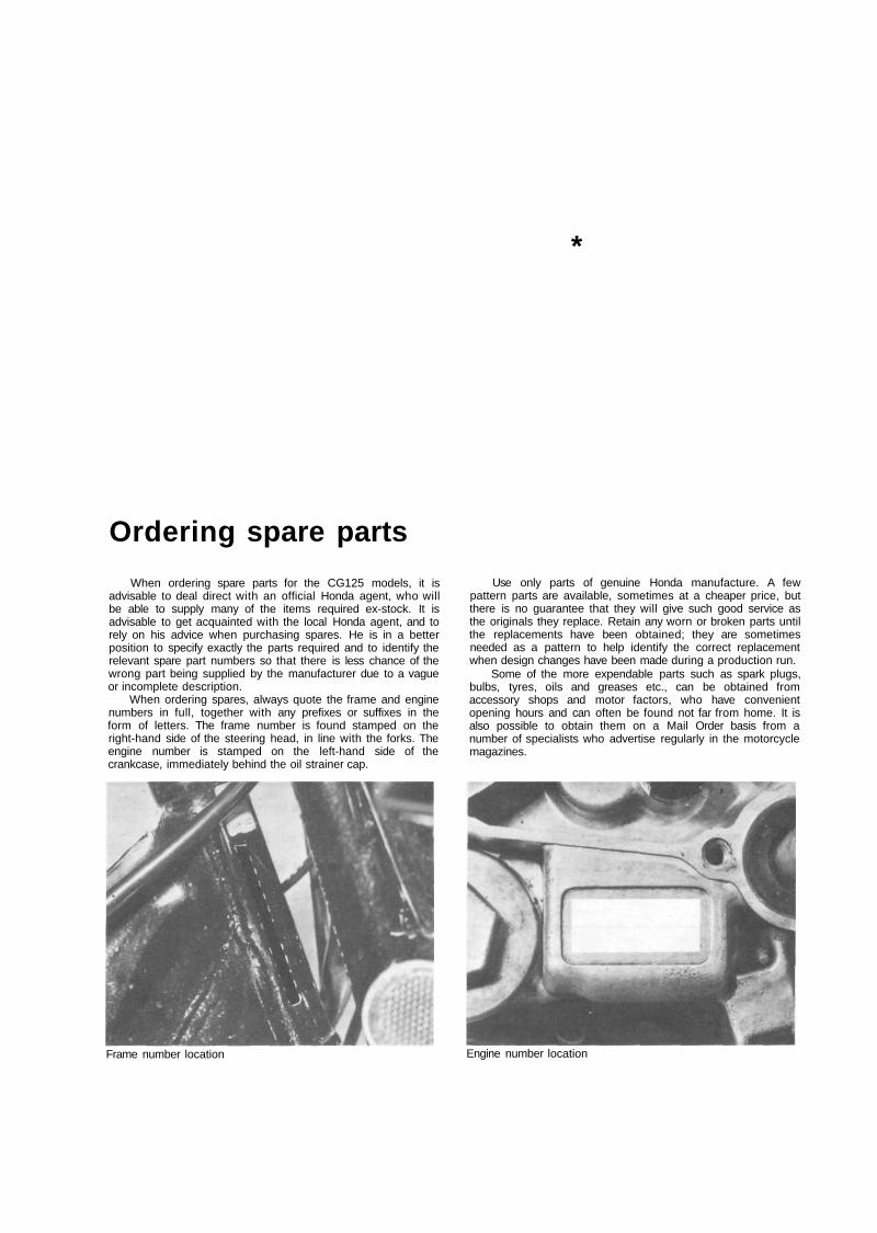
When ordering spares, always quote the frame and enginenumbers in full, together with any prefixes or suffixes in theform of letters. The frame number is found stamped on theright-hand side of the steering head, in line with the forks. Theengine number is stamped on the left-hand side of thecrankcase, immediately behind the oil strainer cap.
Use only parts of genuine Honda manufacture. A fewpattern parts are available, sometimes at a cheaper price, butthere is no guarantee that they will give such good service asthe originals they replace. Retain any worn or broken parts untilthe replacements have been obtained; they are sometimesneeded as a pattern to help identify the correct replacementwhen design changes have been made during a production run.
Some of the more expendable parts such as spark plugs,bulbs, tyres, oils and greases etc., can be obtained fromaccessory shops and motor factors, who have convenientopening hours and can often be found not far from home. It isalso possible to obtain them on a Mail Order basis from anumber of specialists who advertise regularly in the motorcyclemagazines.
Frame number location Engine number location
Safety first!Professional motor mechanics are trained in safe working
procedures. However enthusiastic you may be about getting onwith the job in hand, do take the time to ensure that your safetyis not put at risk. A moments lack of attention can result in anaccident, as can failure to observe certain elementaryprecautions.
There will always be new ways of having accidents, and thefollowing points do not pretend to be a comprehensive list of alldangers; they are intended rather to make you aware of therisks and to encourage a safety-conscious approach to all workyou carry out on your vehicle.
Essential DOs and DON'TsDON'T start the engine without first ascertaining that thetransmission is in neutral.DON'T suddenly remove the filler cap from a hot coolingsystem - cover it with a cloth and release the pressure graduallyfirst, or you may get scalded by escaping coolant.DON'T attempt to drain oil until you are sure it has cooledsufficiently to avoid scalding you.DON'T grasp any part of the engine, exhaust or silencer withoutfirst ascertaining that it is sufficiently cool to avoid burning you.DON'T allow brake fluid or antifreeze to contact the machine'spaintwork or plastic components.DON'T syphon toxic liquids such as fuel, brake fluid orantifreeze by mouth, or allow them to remain on your skin.DON'T inhale dust - it may be injurious to health (see Asbestosheading).DON'T allow any spilt oil or grease to remain on the floor —wipe it up straight away, before someone slips on it.DON'T use ill-fitting spanners or other tools which may slip andcause injury.DON'T attempt to lift a heavy component which may bebeyond your capability - get assistance.DON'T rush to finish a job, or take unverified short cuts.DON'T allow children or animals in or around an unattendedvehicle.DON'T inflate a tyre to a pressure above the recommendedmaximum. Apart from overstressing the carcase and wheel rim,in extreme cases the tyre may blow off forcibly.DO ensure that the machine is supported securely at all times.This is especially important when the machine is blocked up toaid wheel or fork removal.DO take care when attempting to slacken a stubborn nut orbolt. It is generally better to pull on a spanner, rather than push,so that if slippage occurs you fall away from the machine ratherthan on to it.DO wear eye protection when using power tools such as drill,sander, bench grinder etc.DO use a barrier cream on your hands prior to undertaking dirtyjobs — it will protect your skin from infection as well as makingthe dirt easier to remove afterwards; but make sure your handsaren't left slippery. Note that long-term contact with usedengine oil can be a health hazard.DO keep loose clothing (cuffs, tie etc) and long hair well out ofthe way of moving mechanical parts.DO remove rings, wristwatch etc, before working on the vehicle- especially the electrical system.DO keep your work area tidy - it is only too easy to fall overarticles left lying around.DO exercise caution when compressing springs for removal orinstallation. Ensure that the tension is applied and released in acontrolled manner, using suitable tools which preclude thepossibility of the spring escaping violently.DO ensure that any lifting tackle used has a safe working loadrating adequate for the job.DO get someone to check periodically that all is well, whenworking alone on the vehicle.DO carry out work in a logical sequence and check thateverything is correctly assembled and tightened afterwards.DO remember that your vehicle's safety affects that of yourselfand others. If in doubt on any point, get specialist advice.IF, in spite of following these precautions, you are unfortunateenough to injure yourself, seek medical attention as soon aspossible.
AsbestosCertain friction, insulating, sealing, and other products -
such as brake linings, clutch linings, gaskets, etc - containasbestos. Extreme care must be taken to avoid inhalation ofdust from such products since it is hazardous to health. If indoubt, assume that they do contain asbestos.
FireRemember at all times that petrol (gasoline) is highly
flammable. Never smoke, or have any kind of naked flamearound, when working on the vehicle. But the risk does not endthere - a spark caused by an electrical short-circuit, by twometal surfaces contacting each other, by careless use of tools,or even by static electricity built up in your body under certainconditions, can ignite petrol vapour, which in a confined spaceis highly explosive.
Always disconnect the battery earth (ground) terminalbefore working on any part of the fuel or electrical system, andnever risk spilling fuel on to a hot engine or exhaust.
It is recommended that a fire extinguisher of a type suitablefor fuel and electrical fires is kept handy in the garage orworkplace at all times. Never try to extinguish a fuel or electricalfire with water.
Note: Any reference to a 'torch' appearing in this manualshould always be taken to mean a hand-held battery-operatedelectric lamp or flashlight. It does not mean a welding/gas torchor blowlamp.
FumesCertain fumes are highly toxic and can quickly cause
unconsciousness and even death if inhaled to any extent. Petrol(gasoline) vapour comes into this category, as do the vapoursfrom certain solvents such as trichloroethylene. Any draining orpouring of such volatile fluids should be done in a wellventilated area.
When using cleaning fluids and solvents, read the instruc-tions carefully. Never use materials from unmarked containers -they may give off poisonous vapours.
Never run the engine of a motor vehicle in an enclosedspace such as a garage. Exhaust fumes contain carbon mon-oxide which is extremely poisonous; if you need to run theengine, always do so in the open air or at least have the rear ofthe vehicle outside the workplace.
The batteryNever cause a spark, or allow a naked light, near the
vehicle's battery. It will normally be giving off a certain amountof hydrogen gas, which is highly explosive.
Always disconnect the battery earth (ground) terminalbefore working on the fuel or electrical systems.
If possible, loosen the filler plugs or cover when chargingthe battery from an external source. Do not charge at anexcessive rate or the battery may burst.
Take care when topping up and when carrying the battery.The acid electrolyte, even when diluted, is very corrosive andshould not be allowed to contact the eyes or skin.
If you ever need to prepare electrolyte yourself, always addthe acid slowly to the water, and never the other way round.Protect against splashes by wearing rubber gloves and goggles.
Mains electricity and electrical equipmentWhen using an electric power tool, inspection light etc,
always ensure that the appliance is correctly connected to itsplug and that, where necessary, it is properly earthed(grounded). Do not use such appliances in damp conditionsand, again, beware of creating a spark or applying excessiveheat in the vicinity of fuel or fuel vapour. Also ensure that theappliances meet the relevant national safety standards.
Ignition HT voltageA severe electric shock can result from touching certain
parts of the ignition system, such as Ihe HT leads, when theengine is running or being cranked, particularly if componentsare damp or the insulation is defective. Where an electronicignition system is fitted, the HT voltage is much higher andcould prove fatal.
Routine maintenanceRefer to Chapter 7 for information relating to the 1985 on Brazilian models
Introduction
Periodic routine maintenance is a continuous process thatcommences immediately the machine is used. It must becarried out at specified mileage recordings, or on a calendarbasis if the machine is not used frequently, whichever is thesooner. Maintenance should be regarded as an insurance policy,to help keep the machine in the peak of condition and to ensurelong, trouble-free service. It has the additional benefit of givingearly warning of any faults that may develop and will act as aregular safety check, to the obvious advantage of both rider andmachine alike.
The various maintenance tasks are described under theirrespective mileage and calendar headings. Accompanyingdiagrams are provided, where necessary. It should be remem-bered that the interval between the various maintenance tasksserves only as a guide. As the machine gets older or is usedunder particularly adverse conditions, it would be advisable toreduce the period between each check.
For ease of reference each service operation is described indetail under the relevant heading. However, if further generalinformation is required, it can be found within the manual underthe pertinent section heading in the relevant Chapter.
In order that the routine maintenance tasks are carried outwith as much ease as possible, it is essential that a good selec-tion of general workshop tools is available.
Included in the kit must be a range of metric ring or com-bination spanners, a selection of crosshead screwdrivers and atleast one pair of circlip pliers.
Additionally, owing to the extreme tightness of most casingscrews on Japanese machines, an impact screwdriver, togetherwith a choice of large and small crosshead screw bits, isabsolutely indispensable. This is particularly so if the engine hasnot been dismantled since leaving the factory.
prevent the risk of unexpected failure of any component whileriding the machine and, with experience, can be reduced to asimple checklist which will only take a few moments tocomplete. For those owners who are not inclined to check allitems with such frequency, it is suggested that the best courseis to carry out the checks in the form of a service which can beundertaken each week or before any long journey. It is essentialthat all items are checked and serviced with reasonablefrequency.
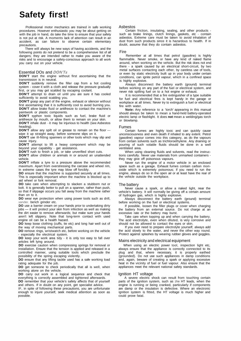
/ Check the engine oil levelWith the machine standing upright on its centre stand on
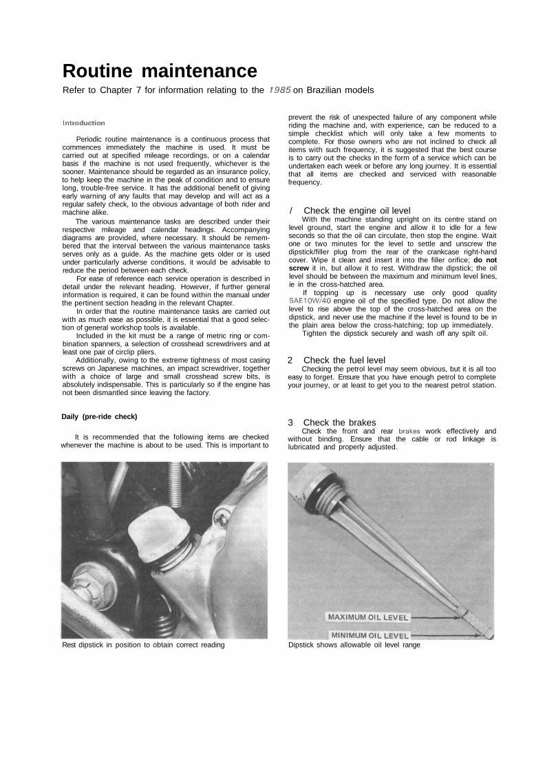
level ground, start the engine and allow it to idle for a fewseconds so that the oil can circulate, then stop the engine. Waitone or two minutes for the level to settle and unscrew thedipstick/filler plug from the rear of the crankcase right-handcover. Wipe it clean and insert it into the filler orifice; do notscrew it in, but allow it to rest. Withdraw the dipstick; the oillevel should be between the maximum and minimum level lines,ie in the cross-hatched area.
If topping up is necessary use only good qualitySAE10W/40 engine oil of the specified type. Do not allow thelevel to rise above the top of the cross-hatched area on thedipstick, and never use the machine if the level is found to be inthe plain area below the cross-hatching; top up immediately.
Tighten the dipstick securely and wash off any spilt oil.
2 Check the fuel levelChecking the petrol level may seem obvious, but it is all too
easy to forget. Ensure that you have enough petrol to completeyour journey, or at least to get you to the nearest petrol station.
Daily (pre-ride check)
It is recommended that the following items are checkedwhenever the machine is about to be used. This is important to
3 Check the brakesCheck the front and rear brakes work effectively and
without binding. Ensure that the cable or rod linkage islubricated and properly adjusted.
Rest dipstick in position to obtain correct reading Dipstick shows allowable oil level range
Routine maintenance
4 Check the tyre pressures and tread wearCheck the tyre pressures with a gauge that is known to be
accurate. It is worthwhile purchasing a pocket gauge for thispurpose because the gauges on garage forecourt airlines arenotoriously inaccurate. The pressures, which should be checkedwith the tyres cold, are specified at the end of Routinemaintenance and in Chapter 5.
At the same time as the tyre pressures are checked,examine the tyres themselves. Check them for damage,especially splitting of the sidewalls. Remove any small stones orother road debris caught between the treads. When checkingthe tyres for damage, they should be examined for tread depthin view of both the legal and safety aspects. It is vital to keepthe tread depth within the UK legal limits of 1 mm of depth overthree-quarters of the tread breadth around the entire circumfer-ence with no bald patches. Many riders, however, considernearer 2 mm to be the limit for secure roadholding, traction, andbraking, especially in adverse weather conditions, and it shouldbe noted that Honda recommend minimum tread depths of 1.5mm (0.06 in) for the front tyre and 2.0 mm (0.08 in) for the rear;these measurements to be taken at the centre of the tread.Renew any tyre that is found to be damaged or excessivelyworn.
5 Safety checkCheck that the front and rear suspension is operating
correctly, that the chain is lubricated and adjusted correctly andthat the battery is in good condition. Check the throttle andclutch cables and levers, the gear lever and the footrests andstand to ensure that they are adjusted correctly, functioningcorrectly, and that all nuts and bolts are securely fastened.
6 Legal checkCheck that all lights, turn signals, horn and speedometer are
working correctly to make sure that the machine complies withall legal requirements in this respect. Check also that theheadlamp is correctly aimed to comply with local legislation.
Monthly or every 600 miles (1000 km)
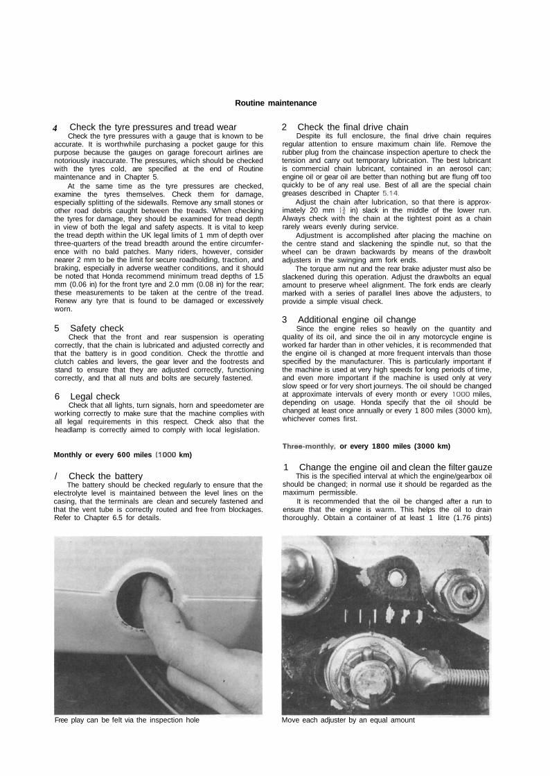
/ Check the batteryThe battery should be checked regularly to ensure that the
electrolyte level is maintained between the level lines on thecasing, that the terminals are clean and securely fastened andthat the vent tube is correctly routed and free from blockages.Refer to Chapter 6.5 for details.
2 Check the final drive chainDespite its full enclosure, the final drive chain requires
regular attention to ensure maximum chain life. Remove therubber plug from the chaincase inspection aperture to check thetension and carry out temporary lubrication. The best lubricantis commercial chain lubricant, contained in an aerosol can;engine oil or gear oil are better than nothing but are flung off tooquickly to be of any real use. Best of all are the special chaingreases described in Chapter 5.14.
Adjust the chain after lubrication, so that there is approx-imately 20 mm (|- in) slack in the middle of the lower run.Always check with the chain at the tightest point as a chainrarely wears evenly during service.
Adjustment is accomplished after placing the machine onthe centre stand and slackening the spindle nut, so that thewheel can be drawn backwards by means of the drawboltadjusters in the swinging arm fork ends.
The torque arm nut and the rear brake adjuster must also beslackened during this operation. Adjust the drawbolts an equalamount to preserve wheel alignment. The fork ends are clearlymarked with a series of parallel lines above the adjusters, toprovide a simple visual check.
3 Additional engine oil changeSince the engine relies so heavily on the quantity and
quality of its oil, and since the oil in any motorcycle engine isworked far harder than in other vehicles, it is recommended thatthe engine oil is changed at more frequent intervals than thosespecified by the manufacturer. This is particularly important ifthe machine is used at very high speeds for long periods of time,and even more important if the machine is used only at veryslow speed or for very short journeys. The oil should be changedat approximate intervals of every month or every 1000 miles,depending on usage. Honda specify that the oil should bechanged at least once annually or every 1 800 miles (3000 km),whichever comes first.
Three-monthly, or every 1800 miles (3000 km)
1 Change the engine oil and clean the filter gauzeThis is the specified interval at which the engine/gearbox oil
should be changed; in normal use it should be regarded as themaximum permissible.
It is recommended that the oil be changed after a run toensure that the engine is warm. This helps the oil to drainthoroughly. Obtain a container of at least 1 litre (1.76 pints)
Free play can be felt via the inspection hole Move each adjuster by an equal amount
'
10 Routine maintenance
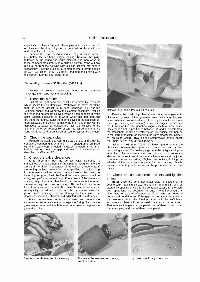
capacity and place it beneath the engine unit to catch the oldoil. Unscrew the drain plug on the underside of the crankcaseand allow the oil to drain.
Remove the large hexagon-headed plug which is locatedjust below the left-hand engine casing. Remove the plug,followed by the spring and gauze element, and then wash allthese components carefully in a suitable solvent. Wipe out anyresidual oil from the housing with a clean lint-free rag prior toreassembly. Refit the drain plug, tightening it to a torque settingof 2.0 - 3.5 kgf m (14.5 - 25 Ibf ft), and refill the engine withthe correct quantity and grade of oil.
Six-monthly, or every 3600 miles (6000 km)
Repeat all service operations listed under previousheadings, then carry out the following:
/ Clean the air filterPull off the right-hand side panel and remove the two nuts
which secure the air filter cover. Withdraw the cover, checkingthat the sealing gasket is in good condition, pull out theretaining spring and withdraw the element assembly. Peel offthe inner and outer foam sleeves. Wash all components in whitespirit (Stoddard solvent) or in warm water and detergent anddry them thoroughly. Soak the foam sleeves in the specified oil,then squeeze them gently (do not wring them out or they will bedamaged) to expel all surplus oil. Refit the sleeves to theelement frame. On reassembly ensure that all components arecorrectly fitted so that unfiltered air cannot bypass the element.
2 Check the spark plugRemove the spark plug cap, unscrew the plug and check its
condition, comparing it with the photographs on page65. If it is badly worn or fouled it must be renewed. If it is fit forfurther service check the gap and reset it if necessary, asdescribed in Chapter 3.8.
3 Check the valve clearancesIt is important that the correct valve clearance is
maintained. A small amount of free play is designed into thevalve train to allow for expansion of the various components. Ifthe setting deviates greatly from that specified, a marked dropin performance will be evident. In the case of the clearancebecoming too great, it will be found that valve operation will benoisy, and performance will drop off as a result of the valves notopening fully. If on the other hand, the clearance is too smallthe valves may not close completely. This will not only causeloss of compression, but will also cause the valves to burn outvery quickly. In extreme cases, a valve head may strike thepiston crown, causing extensive damage to the engine. Theclearances should be checked and adjusted with a cold engine.
Place the machine on its centre stand and remove therocker cover, taking care not to damage the 0 ring. Remove thegearchange pedal and the left-hand outer cover to expose thegenerator rotor.
Remove plug and allow old oil to drain
Remove the spark plug, then slowly rotate the engine anti-clockwise by way of the generator rotor, watching the inletvalve. When it has opened and closed again (sunk down andrisen up to its original position), rotate the engine further untilthe T mark on the rotor periphery aligns exactly with the raisedindex mark which is positioned between 12 and 1 o'clock (fromthe crankshaft) on the generator stator. The engine will then bein the correct position for checking the valve clearances, namelyat Top Dead Centre (TDC) on the compression stroke; checkthat there is free play at both rockers.
Using a 0.08 mm (0.003 in) feeler gauge, check theclearance between the top of each valve stem and its cor-responding rocker. The feeler gauge must be a light sliding fit,with the rocker and valve stem just nipping it. If necessary,slacken the locknut, and turn the small square-headed adjusterto obtain the correct setting. Tighten the locknut, holding theadjuster at the same time to prevent it from moving. Finally,recheck the setting and then repeat the procedure on the otherrocker.
4 Check the contact breaker points and ignitiontiming
Note: since the generator stator plate is located by itscountersunk retaining screws, the ignition timing can only bealtered by opening or closing the contact breaker gap; thereforeboth operations are described as one. The full procedure isgiven here for ease of reference, but if the points are found tobe in good condition and if the gap has not altered or is withinthe tolerance, then the ignition timing will be sufficientlyaccurate and there will be no need to carry out the full check.First remove the gearchange pedal, the left-hand outer cover,the spark plug and the left-hand side panel.
Strainer is easily removed for cleaning Dismantle the element for cleaning -j- mark should align as shownand lubrication

Routine maintenance 11
Checking the condition of the contact breaker pointsThe contact breaker assembly can be viewed through one
of the generator rotor slots; turn the rotor until the points open.Use a small screwdriver to push the moving point open againstits spring. Examine the point contact faces. If they are burnt orpitted, remove the points for cleaning or renewal, see Chapter3.4. Light surface deposits can be removed with crocus paper ora piece of stiff card.
If the contact faces are badly burnt or pitted, or if themoving contact fibre heel shows signs of wear or damage,renew the assembly. It is essential that the points are in goodcondition if the ignition timing is to be correct; use only genuineHonda parts when renewing. If the faces are only mildlymarked, clean them using an oilstone or fine emery but becareful to keep them square. If it is necessary to separate themoving contact from the fixed one, carefully remove the circlipfitted to the pivot post and note carefully the arrangement ofwashers at both the pivot post and spring blade fixing. Onreassembly, the moving contact must be able to move freely;apply a smear of grease to the pivot post. Note also that the lowtension lead terminal and the moving contact spring blade mustbe connected to each other via the small bolt, but that bothmust be completely insulated from the fixed contact. The enginewill not run if a short-circuit occurs at this point.
Refit the points to the stator plate and the rotor to thecrankshaft. Tighten the rotor nut to a torque setting of 4.0 - 5.0kgf m (29 - 36 Ibf ft), then apply a few drops of oil to the camlubricating wick.
Checking the ignition timingDisconnect the generator wiring at the connector block
joining it to the main wiring loom and identify the black orblack/white wire leading to the points. The best way ofestablishing exactly when the points open is to use either amultimeter set to its most sensitive resistance scale, or abattery and bulb test circuit; refer to Chapter 3 for details. Themeter needle will flicker to indicate increased resistance as thepoints open, or the bulb (which will be lit when the points areclosed) will glow dimmer; note that a high-wattage bulb mustbe used to make this more obvious to the eye.
Turn the rotor anticlockwise until the meter needle deflects(or the bulb dims); at this point the rotor 'F' mark should alignexactly with the raised index mark on the stator plate.
The setting is adjusted by opening or closing the points gapto advance or retard respectively the ignition timing. Repeat theprocedure to check that the timing is now correct.
When the timing is correct, measure very carefully thepoints gap, to ensure that the dwell angle is correct for themaximum spark intensity. If the gap is found to be outside thepermitted tolerance the contact breaker points are excessivelyworn and must be renewed.
Fit a new set of contact breaker points; note that it isessential that only genuine Honda points are used. Refit therotor and set the points gap to exactly 0.35 mm (0.014 in), then
repeat the procedure given above. The ignition timing should becorrect.
Note: The above procedure is described in full as it is themost accurate means of setting the ignition timing. In practicethere is no need to repeat the full procedure at every serviceinterval. Instead it is sufficient to check that the points gap iswithin tolerances.
If a strobe timing light is available the ATU's performancecan be checked. Connect the light following its manufacturer'sinstructions, then start the engine and allow it to idle. At idlespeed the 'F mark should align with the raised index mark; atjust above idle speed the mark should appear to move as theadvance begins until at 3000 rpm the two parallel lines of thefull advance mark are aligned with the index mark. If themovement is stiff and jerky, or if the advance range is restricted,the rotor must be removed so that the ATU can be dismantledfor cleaning and greasing.
5 General checks and lubricationAt regular intervals the control cables must be thoroughly
lubricated, using light machine oil. This can be done by eitherdisconnecting the cable upper end and fitting a proprietarycable oiler to pump oil through, or by removing the cable fromthe machine and hanging it up overnight so that oil can drainthrough the cable from a small funnel attached to its upper end.Ensure that the cables are correctly routed and adjusted onrefitting. Grease the speedometer drive cable as described inChapter 4.17.
Check all pivots and control levers, cleaning and lubricatingthem to prevent wear or corrosion. Where necessary, dismantleand clean any moving part which may have become stiff inoperation. Similarly clean, check and grease the stand pivotsand ensure that the return spring holds the stand securely.
Check around the machine, looking for. loose nuts, bolts orscrews, retightening them as necessary.
It is advisable to lubricate the handlebar switches and stoplamp switches with WD40 or a similar water dispersantlubricant.
6 Check the fuel systemReferring to the relevant Sections of Chapter 2 (or of
Chapter 7 for (T)PFC carburettors) for full details check that thepetrol tank, tap, and feed pipe are in good condition andsecurely fastened with no leaks. Check also that the chokeoperates correctly. If rough running of the engine hasdeveloped, some adjustment of the carburettor pilot setting andtickover speed may be required. Do not make theseadjustments unless they are obviously required; there is little tobe gained by unwarranted attention to the carburettor.
Switch on the petrol tap and unscrew the float bowl drainplug, allowing a small quantity of petrol to flush through. If largeamounts of dirt or water are found in the petrol, the systemcomponents must be drained and cleaned out.
Once the carburettor has been checked and reset ifnecessary, the throttle cable free play can be checked. Open
Set clearance so that the feeler gaugeis a sliding fit
"F" mark should align just as pointsseparate
Contact breaker gap is measuredvia aperture
12 Routine maintenance
and close the throttle several times, allowing it to snap shutunder its own pressure. Ensure that it is able to shut off quicklyand fully at all handlebar positions, then check that there is 2 —6 mm (0.08 - 0.24 in) of cable free play, measured in terms oftwistgrip rotation. If adjustment is necessary, use first theadjuster which is set below the twistgrip. If there is aninsufficient range of adjustment the surplus free play can beeliminated by peeling back the rubber cover and by using theadjuster on the carburettor top.
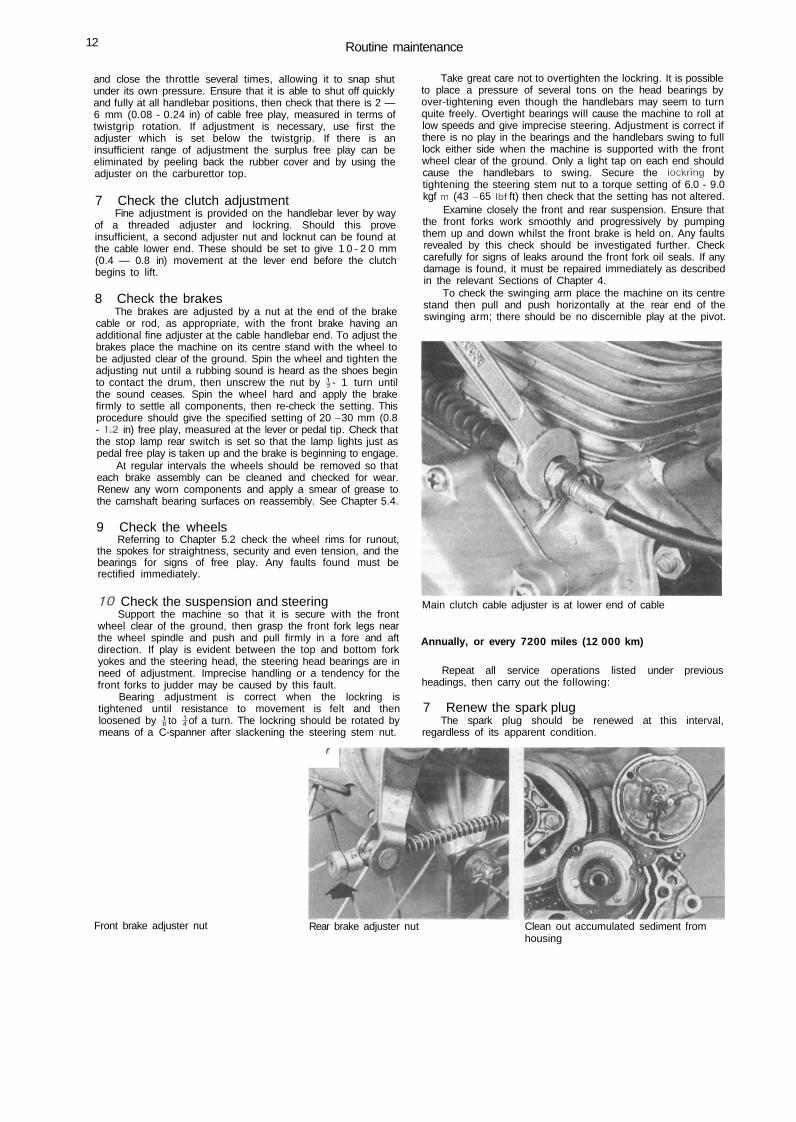
7 Check the clutch adjustmentFine adjustment is provided on the handlebar lever by way
of a threaded adjuster and lockring. Should this proveinsufficient, a second adjuster nut and locknut can be found atthe cable lower end. These should be set to give 1 0 - 2 0 mm(0.4 — 0.8 in) movement at the lever end before the clutchbegins to lift.
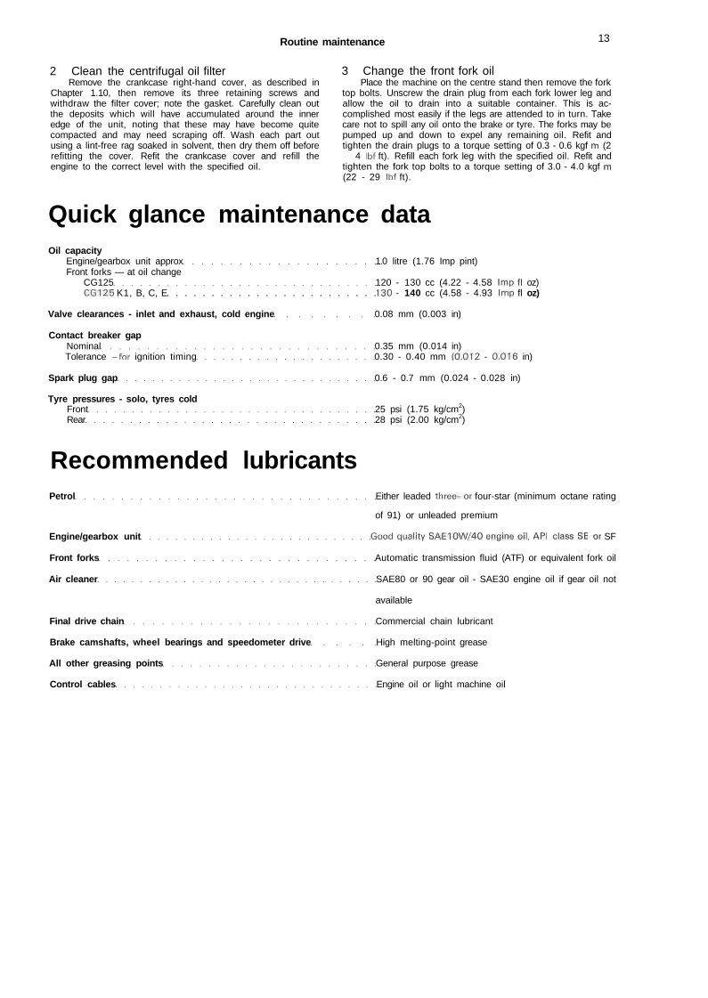
8 Check the brakesThe brakes are adjusted by a nut at the end of the brake
cable or rod, as appropriate, with the front brake having anadditional fine adjuster at the cable handlebar end. To adjust thebrakes place the machine on its centre stand with the wheel tobe adjusted clear of the ground. Spin the wheel and tighten theadjusting nut until a rubbing sound is heard as the shoes beginto contact the drum, then unscrew the nut by \ - 1 turn untilthe sound ceases. Spin the wheel hard and apply the brakefirmly to settle all components, then re-check the setting. Thisprocedure should give the specified setting of 20 - 30 mm (0.8- 1.2 in) free play, measured at the lever or pedal tip. Check thatthe stop lamp rear switch is set so that the lamp lights just aspedal free play is taken up and the brake is beginning to engage.
At regular intervals the wheels should be removed so thateach brake assembly can be cleaned and checked for wear.Renew any worn components and apply a smear of grease tothe camshaft bearing surfaces on reassembly. See Chapter 5.4.
9 Check the wheelsReferring to Chapter 5.2 check the wheel rims for runout,
the spokes for straightness, security and even tension, and thebearings for signs of free play. Any faults found must berectified immediately.
10 Check the suspension and steeringSupport the machine so that it is secure with the front
wheel clear of the ground, then grasp the front fork legs nearthe wheel spindle and push and pull firmly in a fore and aftdirection. If play is evident between the top and bottom forkyokes and the steering head, the steering head bearings are inneed of adjustment. Imprecise handling or a tendency for thefront forks to judder may be caused by this fault.
Bearing adjustment is correct when the lockring istightened until resistance to movement is felt and thenloosened by \ to \ of a turn. The lockring should be rotated bymeans of a C-spanner after slackening the steering stem nut.
'
Take great care not to overtighten the lockring. It is possibleto place a pressure of several tons on the head bearings byover-tightening even though the handlebars may seem to turnquite freely. Overtight bearings will cause the machine to roll atlow speeds and give imprecise steering. Adjustment is correct ifthere is no play in the bearings and the handlebars swing to fulllock either side when the machine is supported with the frontwheel clear of the ground. Only a light tap on each end shouldcause the handlebars to swing. Secure the lockring bytightening the steering stem nut to a torque setting of 6.0 - 9.0kgf m (43 - 65 Ibf ft) then check that the setting has not altered.
Examine closely the front and rear suspension. Ensure thatthe front forks work smoothly and progressively by pumpingthem up and down whilst the front brake is held on. Any faultsrevealed by this check should be investigated further. Checkcarefully for signs of leaks around the front fork oil seals. If anydamage is found, it must be repaired immediately as describedin the relevant Sections of Chapter 4.
To check the swinging arm place the machine on its centrestand then pull and push horizontally at the rear end of theswinging arm; there should be no discernible play at the pivot.
Main clutch cable adjuster is at lower end of cable
Annually, or every 7200 miles (12 000 km)
Repeat all service operations listed under previousheadings, then carry out the following:
7 Renew the spark plugThe spark plug should be renewed at this interval,
regardless of its apparent condition.
Front brake adjuster nut Rear brake adjuster nut Clean out accumulated sediment fromhousing
Routine maintenance 13
2 Clean the centrifugal oil filterRemove the crankcase right-hand cover, as described in
Chapter 1.10, then remove its three retaining screws andwithdraw the filter cover; note the gasket. Carefully clean outthe deposits which will have accumulated around the inneredge of the unit, noting that these may have become quitecompacted and may need scraping off. Wash each part outusing a lint-free rag soaked in solvent, then dry them off beforerefitting the cover. Refit the crankcase cover and refill theengine to the correct level with the specified oil.
3 Change the front fork oilPlace the machine on the centre stand then remove the fork
top bolts. Unscrew the drain plug from each fork lower leg andallow the oil to drain into a suitable container. This is ac-complished most easily if the legs are attended to in turn. Takecare not to spill any oil onto the brake or tyre. The forks may bepumped up and down to expel any remaining oil. Refit andtighten the drain plugs to a torque setting of 0.3 - 0.6 kgf m (2— 4 Ibf ft). Refill each fork leg with the specified oil. Refit andtighten the fork top bolts to a torque setting of 3.0 - 4.0 kgf m(22 - 29 Ibf ft).
Quick glance maintenance dataOil capacity
Engine/gearbox unit approx 1.0 litre (1.76 Imp pint)Front forks — at oil change
CG125 120 - 130 cc (4.22 - 4.58 Imp fl oz)CG125 K1, B, C, E 130 - 140 cc (4.58 - 4.93 Imp fl oz)
Valve clearances - inlet and exhaust, cold engine 0.08 mm (0.003 in)
Contact breaker gapNominal 0.35 mm (0.014 in)Tolerance - for ignition timing 0.30 - 0.40 mm (0.012 - 0.016 in)
Spark plug gap 0.6 - 0.7 mm (0.024 - 0.028 in)
Tyre pressures - solo, tyres coldFront 25 psi (1.75 kg/cm2)Rear 28 psi (2.00 kg/cm2)
Recommended lubricantsPetrol Either leaded three-or four-star (minimum octane rating
of 91) or unleaded premium
Engine/gearbox unit Good quality SAE10W/40 engine oil, API class SE or SF
Front forks Automatic transmission fluid (ATF) or equivalent fork oil
Air cleaner SAE80 or 90 gear oil - SAE30 engine oil if gear oil not
available
Final drive chain Commercial chain lubricant
Brake camshafts, wheel bearings and speedometer drive High melting-point grease
All other greasing points General purpose grease
Control cables Engine oil or light machine oil
Working conditions and tools
When a major overhaul is contemplated, it is important thata clean, well-lit working space is available, equipped with aworkbench and vice, and with space for laying out or storing thedismantled assemblies in an orderly manner where they areunlikely to be disturbed. The use of a good workshop will givethe satisfaction of work done in comfort and without haste,where there is little chance of the machine being dismantledand reassembled in anything other than clean surroundings.Unfortunately, these ideal working conditions are not alwayspracticable and under these latter circumstances whenimprovisation is called for, extra care and time will be needed.
The other essential requirement is a comprehensive set ofgood quality tools. Quality is of prime importance since cheaptools will prove expensive in the long run if they slip or breakwhen in use, causing personal injury or expensive damage tothe component being worked on. A good quality tool will last along time, and more than justify the cost.
For practically all tools, a tool factor is the best source sincehe will have a very comprehensive range compared with theaverage garage or accessory shop. Having said that, accessoryshops often offer excellent quality tools at discount prices, so itpays to shop around. There are plenty of tools around atreasonable prices, but always aim to purchase items which meetthe relevant national safety standards. If in doubt, seek theadvice of the shop proprietor or manager before making apurchase.
The basis of any tool kit is a set of open-ended spanners,which can be used on almost any part of the machine to whichthere is reasonable access. A set of ring spanners makes a usefuladdition, since they can be used on nuts that are very tight orwhere access is restricted. Where the cost has to be kept withinreasonable bounds, a compromise can be effected with a set ofcombination spanners - open-ended at one end and having aring of the same size on the other end. Socket spanners may alsobe considered a good investment, a basic 3/8 in or 1/2 in drivekit comprising a ratchet handle and a small number of socketheads, if money is limited. Additional sockets can be purchased,as and when they are required. Provided they are slim in profile,sockets will reach nuts or bolts that are deeply recessed. Whenpurchasing spanners of any kind, make sure the correct sizestandard is purchased. Almost all machines manufacturedoutside the UK and the USA have metric nuts and bolts, whilstthose produced in Britain have BSF or BSW sizes. The standardused in USA is AF, which is also found on some of the laterBritish machines. Others tools that should be included in the kitare a range of crosshead screwdrivers, a pair of pliers and ahammer.
When considering the purchase of tools, it should beremembered that by carrying out the work oneself, a largeproportion of the normal repair cost, made up by labourcharges, will be saved. The economy made on even a minoroverhaul will go a long way towards the improvement of atoolkit.
In addition to the basic tool kit, certain additional tools canprove invaluable when they are close to hand, to help speed upa multitude of repetitive jobs. For example, an impactscrewdriver will ease the removal of screws that have beentightened by a similar tool, during assembly, Without a risk ofdamaging the screw heads. And, of course, it can be used againto retighten the screws, to ensure an oil or airtight seal results.Circlip pliers have their uses too, since gear pinions, shafts andsimilar components are frequently retained by circlips that arenot too easily displaced by a screwdriver. There are two types ofcirclip pliers, one for internal and one for external circlips. Theymay also have straight or right-angled jaws.
One of the most useful of all tools is the torque wrench, aform of spanner that can be adjusted to slip when a measuredamount of force is applied to any bolt or nut. Torque wrenchsettings are given in almost every modern workshop or servicemanual, where the extent to which a complex component, suchas a cylinder head, can be tightened without fear of distortion orleakage. The tightening of bearing caps is yet another example.Overtightening will stretch or even break bolts, necessitatingextra work to extract the broken portions.
As may be expected, the more sophisticated the machine,the greater is the number of tools likely to be required if it is tobe kept in first class condition by the home mechanic.Unfortunately there are certain jobs which cannot beaccomplished successfully without the correct equipment andalthough there is invariably a specialist who will undertake thework for a fee, the home mechanic will have to dig more deeplyin his pocket for the purchase of similar equipment if he doesnot wish to employ the services of others. Here a word ofcaution is necessary, since some of these jobs are best left tothe expert. Although an electrical multimeter of the AVO typewill prove helpful in tracing electrical faults, in inexperiencedhands it may irrevocably damage some of the electrical com-ponents if a test current is passed through them in the wrongdirection. This can apply to the synchronisation of twin or mul-tiple carburettors too, where a certain amount of expertise isneeded when setting them up with vacuum gauges. These are,however, exceptions. Some instruments, such as a strobe lamp,are virtually essential when checking the timing of a machinepowered by CDI ignition system. In short, do not purchase anyof these special items unless you have the experience to usethem correctly.
Although this manual shows how components can beremoved and replaced without the use of special service tools(unless absolutely essential), it is worthwhile giving considera-tion to the purchase of the more commonly used tools if themachine is regarded as a long term purchase Whilst the alterna-tive methods suggested will remove and replace parts withoutrisk of damage, the use of the special tools recommended andsold by the manufacturer will invariably save time.
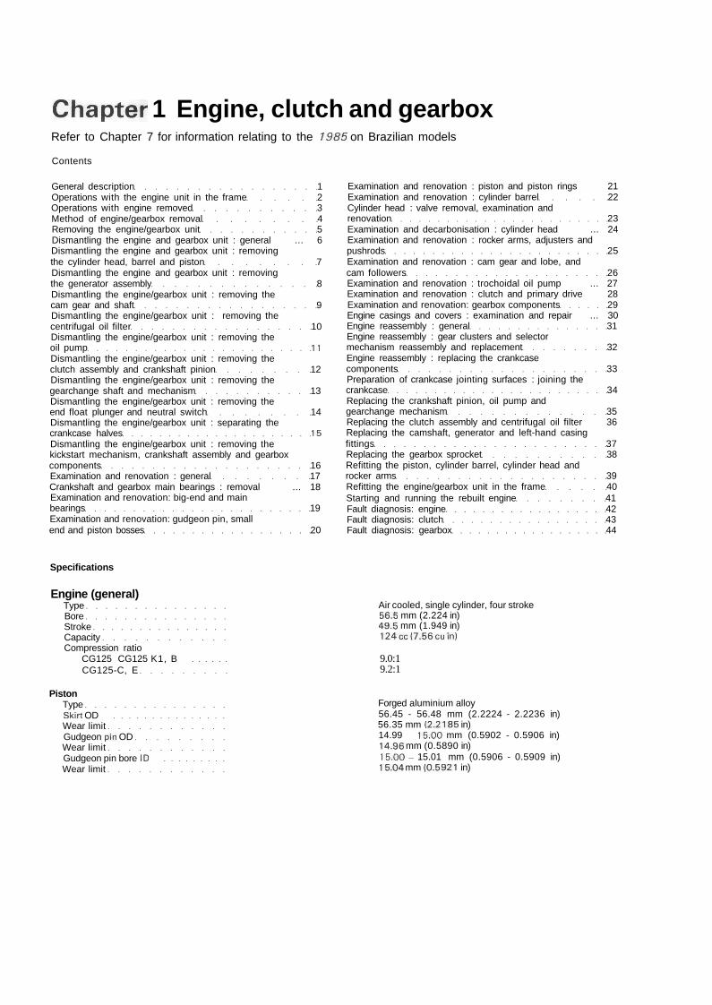
Chapter 1 Engine, clutch and gearboxRefer to Chapter 7 for information relating to the 1985 on Brazilian models
Contents
General description 1Operations with the engine unit in the frame 2Operations with engine removed 3Method of engine/gearbox removal 4Removing the engine/gearbox unit 5Dismantling the engine and gearbox unit : general ... 6Dismantling the engine and gearbox unit : removingthe cylinder head, barrel and piston 7Dismantling the engine and gearbox unit : removingthe generator assembly 8Dismantling the engine/gearbox unit : removing thecam gear and shaft 9Dismantling the engine/gearbox unit : removing thecentrifugal oil filter 10Dismantling the engine/gearbox unit : removing theoil pump 11Dismantling the engine/gearbox unit : removing theclutch assembly and crankshaft pinion 12Dismantling the engine/gearbox unit : removing thegearchange shaft and mechanism 13Dismantling the engine/gearbox unit : removing theend float plunger and neutral switch 14Dismantling the engine/gearbox unit : separating thecrankcase halves 15Dismantling the engine/gearbox unit : removing thekickstart mechanism, crankshaft assembly and gearboxcomponents 16Examination and renovation : general 17Crankshaft and gearbox main bearings : removal ... 18Examination and renovation: big-end and mainbearings 19Examination and renovation: gudgeon pin, smallend and piston bosses 20
Examination and renovation : piston and piston rings 21Examination and renovation : cylinder barrel 22Cylinder head : valve removal, examination andrenovation 23Examination and decarbonisation : cylinder head ... 24Examination and renovation : rocker arms, adjusters andpushrods 25Examination and renovation : cam gear and lobe, andcam followers 26Examination and renovation : trochoidal oil pump ... 27Examination and renovation : clutch and primary drive 28Examination and renovation: gearbox components 29Engine casings and covers : examination and repair ... 30Engine reassembly : general 31Engine reassembly : gear clusters and selectormechanism reassembly and replacement 32Engine reassembly : replacing the crankcasecomponents 33Preparation of crankcase jointing surfaces : joining thecrankcase 34Replacing the crankshaft pinion, oil pump andgearchange mechanism 35Replacing the clutch assembly and centrifugal oil filter 36Replacing the camshaft, generator and left-hand casingfittings 37Replacing the gearbox sprocket 38Refitting the piston, cylinder barrel, cylinder head androcker arms 39Refitting the engine/gearbox unit in the frame 40Starting and running the rebuilt engine 41Fault diagnosis: engine 42Fault diagnosis: clutch 43Fault diagnosis: gearbox 44
Specifications
Engine (general)TypeBoreStrokeCapacityCompression ratio
CG125 CG125 K1, BCG125-C, E
PistonTypeSkirt ODWear limitGudgeon pin ODWear limitGudgeon pin bore IDWear limit
Air cooled, single cylinder, four stroke56.5 mm (2.224 in)49.5 mm (1.949 in)124cc(7.56cuin)
9.0:19.2:1
Forged aluminium alloy56.45 - 56.48 mm (2.2224 - 2.2236 in)56.35 mm (2.2185 in)14.99 - 15.00 mm (0.5902 - 0.5906 in)14.96 mm (0.5890 in)15.00 - 15.01 mm (0.5906 - 0.5909 in)15.04 mm (0.5921 in)
16 Chapter 1 Engine, clutch and gearbox
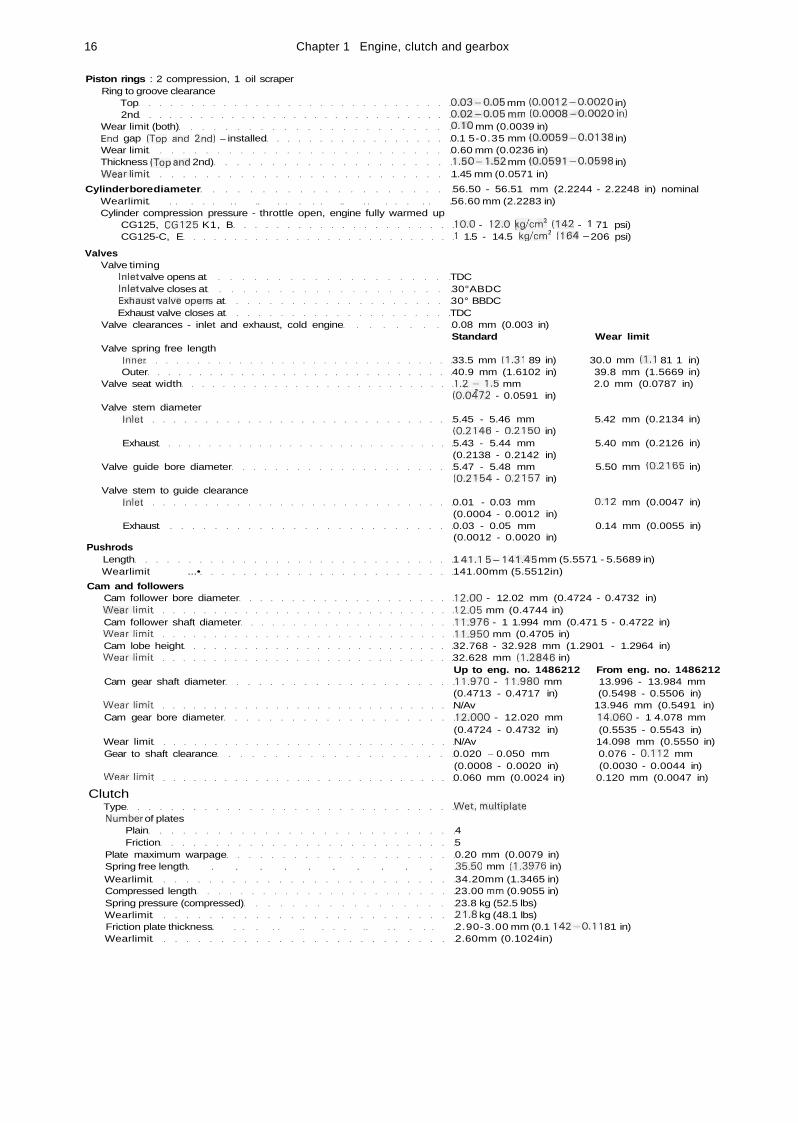
Piston rings : 2 compression, 1 oil scraperRing to groove clearance
Top 0.03-0.05 mm (0.0012-0.0020 in)2nd 0.02-0.05 mm (0.0008-0.0020in)
Wear limit (both) 0.10 mm (0.0039 in)End gap (Top and 2nd) - installed 0.1 5-0.35 mm (0.0059-0.0138 in)Wear limit 0.60 mm (0.0236 in)Thickness (Top and 2nd) 1.50-1.52 mm (0.0591-0.0598 in)Wearlimit 1.45 mm (0.0571 in)
Cylinder bore diameter 56.50 - 56.51 mm (2.2244 - 2.2248 in) nominalWearlimit 56.60 mm (2.2283 in)Cylinder compression pressure - throttle open, engine fully warmed up
CG125, CG125 K1, B 10.0 - 12.0 kg/cm2 (142 - 1 71 psi)CG125-C, E 1 1.5 - 14.5 kg/cm2 (164 - 206 psi)
ValvesValve timing
Inlet valve opens at TDCInlet valve closes at 30°ABDCExhaust valve operTs at 30° BBDCExhaust valve closes at TDC
Valve clearances - inlet and exhaust, cold engine 0.08 mm (0.003 in)Standard Wear limit
Valve spring free lengthInner 33.5 mm (1.31 89 in) 30.0 mm (1.1 81 1 in)Outer 40.9 mm (1.6102 in) 39.8 mm (1.5669 in)
Valve seat width 1.2-1.5 mm 2.0 mm (0.0787 in)(0.04"72 - 0.0591 in)
Valve stem diameterInlet 5.45 - 5.46 mm 5.42 mm (0.2134 in)
(0.2146 - 0.2150 in)Exhaust 5.43 - 5.44 mm 5.40 mm (0.2126 in)
(0.2138 - 0.2142 in)Valve guide bore diameter 5.47 - 5.48 mm 5.50 mm (0.2165 in)
(0.2154 - 0.2157 in)Valve stem to guide clearance
Inlet 0.01 - 0.03 mm 0.12 mm (0.0047 in)(0.0004 - 0.0012 in)
Exhaust 0.03 - 0.05 mm 0.14 mm (0.0055 in)(0.0012 - 0.0020 in)
PushrodsLength 1 41.1 5-141.45 mm (5.5571 - 5.5689 in)Wearlimit ...• 141.00mm (5.5512in)
Cam and followersCam follower bore diameter 12.00 - 12.02 mm (0.4724 - 0.4732 in)Wearlimit 12.05 mm (0.4744 in)Cam follower shaft diameter 11.976 - 1 1.994 mm (0.471 5 - 0.4722 in)Wearlimit 11.950 mm (0.4705 in)Cam lobe height 32.768 - 32.928 mm (1.2901 - 1.2964 in)Wearlimit 32.628 mm (1.2846 in)
Up to eng. no. 1486212 From eng. no. 1486212Cam gear shaft diameter 11.970 - 11.980 mm 13.996 - 13.984 mm
(0.4713 - 0.4717 in) (0.5498 - 0.5506 in)Wearlimit N/Av 13.946 mm (0.5491 in)Cam gear bore diameter 12.000 - 12.020 mm 14.060 - 1 4.078 mm
(0.4724 - 0.4732 in) (0.5535 - 0.5543 in)Wear limit N/Av 14.098 mm (0.5550 in)Gear to shaft clearance 0.020 - 0.050 mm 0.076 - 0.112 mm
(0.0008 - 0.0020 in) (0.0030 - 0.0044 in)Wearlimit 0.060 mm (0.0024 in) 0.120 mm (0.0047 in)
ClutchType Wet, multiplateNumber of plates
Plain 4Friction 5
Plate maximum warpage 0.20 mm (0.0079 in)Spring free length 35.50 mm (1.3976 in)Wearlimit 34.20mm (1.3465 in)Compressed length 23.00 mm (0.9055 in)Spring pressure (compressed) 23.8 kg (52.5 lbs)Wearlimit 21.8 kg (48.1 lbs)Friction plate thickness 2.90-3.00 mm (0.1 142-0.11 81 in)Wearlimit 2.60mm (0.1024in)
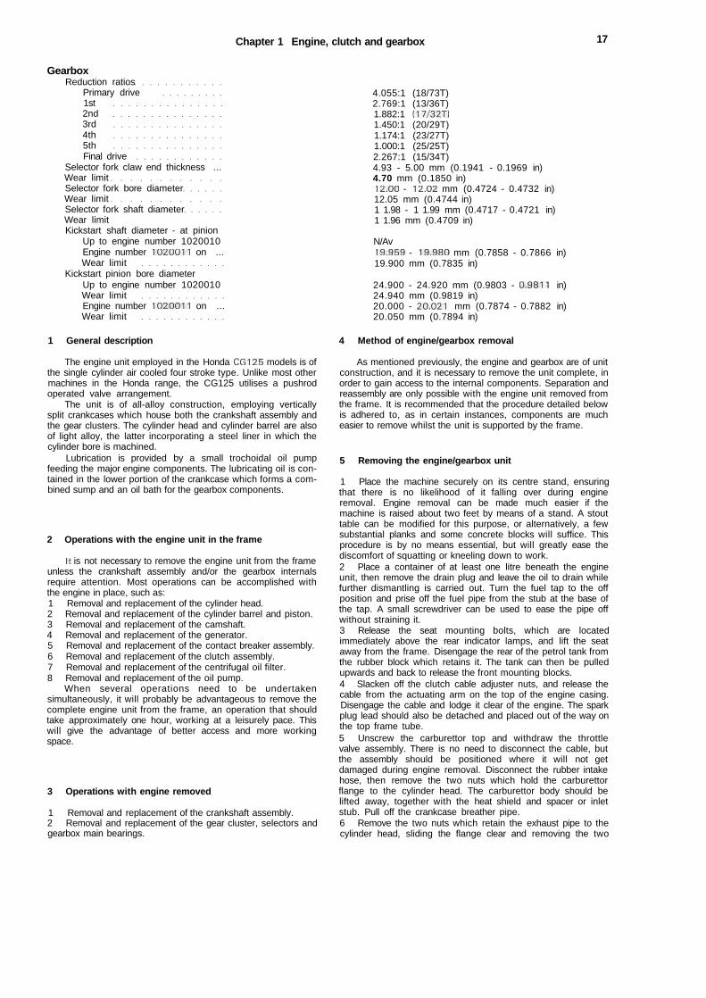
Chapter 1 Engine, clutch and gearbox 17
GearboxReduction ratios
Primary drive1st2nd3rd4th5thFinal drive
Selector fork claw end thickness ...Wear limitSelector fork bore diameterWear limitSelector fork shaft diameterWear limitKickstart shaft diameter - at pinion
Up to engine number 1020010Engine number 1020011 on ...Wear limit
Kickstart pinion bore diameterUp to engine number 1020010Wear limitEngine number 1020011 on ...Wear limit
1 General description
The engine unit employed in the Honda CG125 models is ofthe single cylinder air cooled four stroke type. Unlike most othermachines in the Honda range, the CG125 utilises a pushrodoperated valve arrangement.
The unit is of all-alloy construction, employing verticallysplit crankcases which house both the crankshaft assembly andthe gear clusters. The cylinder head and cylinder barrel are alsoof light alloy, the latter incorporating a steel liner in which thecylinder bore is machined.
Lubrication is provided by a small trochoidal oil pumpfeeding the major engine components. The lubricating oil is con-tained in the lower portion of the crankcase which forms a com-bined sump and an oil bath for the gearbox components.
2 Operations with the engine unit in the frame
It is not necessary to remove the engine unit from the frameunless the crankshaft assembly and/or the gearbox internalsrequire attention. Most operations can be accomplished withthe engine in place, such as:1 Removal and replacement of the cylinder head.2 Removal and replacement of the cylinder barrel and piston.3 Removal and replacement of the camshaft.4 Removal and replacement of the generator.5 Removal and replacement of the contact breaker assembly.6 Removal and replacement of the clutch assembly.7 Removal and replacement of the centrifugal oil filter.8 Removal and replacement of the oil pump.
When several operations need to be undertakensimultaneously, it will probably be advantageous to remove thecomplete engine unit from the frame, an operation that shouldtake approximately one hour, working at a leisurely pace. Thiswill give the advantage of better access and more workingspace.
3 Operations with engine removed
1 Removal and replacement of the crankshaft assembly.2 Removal and replacement of the gear cluster, selectors andgearbox main bearings.
4.055:1 (18/73T)2.769:1 (13/36T)1.882:1 (17/32T)1.450:1 (20/29T)1.174:1 (23/27T)1.000:1 (25/25T)2.267:1 (15/34T)4.93 - 5.00 mm (0.1941 - 0.1969 in)4.70 mm (0.1850 in)12.00 - 12.02 mm (0.4724 - 0.4732 in)12.05 mm (0.4744 in)1 1.98 - 1 1.99 mm (0.4717 - 0.4721 in)1 1.96 mm (0.4709 in)
N/Av19.959 - 19.980 mm (0.7858 - 0.7866 in)19.900 mm (0.7835 in)
24.900 - 24.920 mm (0.9803 - 0.9811 in)24.940 mm (0.9819 in)20.000 - 20.021 mm (0.7874 - 0.7882 in)20.050 mm (0.7894 in)
4 Method of engine/gearbox removal
As mentioned previously, the engine and gearbox are of unitconstruction, and it is necessary to remove the unit complete, inorder to gain access to the internal components. Separation andreassembly are only possible with the engine unit removed fromthe frame. It is recommended that the procedure detailed belowis adhered to, as in certain instances, components are mucheasier to remove whilst the unit is supported by the frame.
5 Removing the engine/gearbox unit
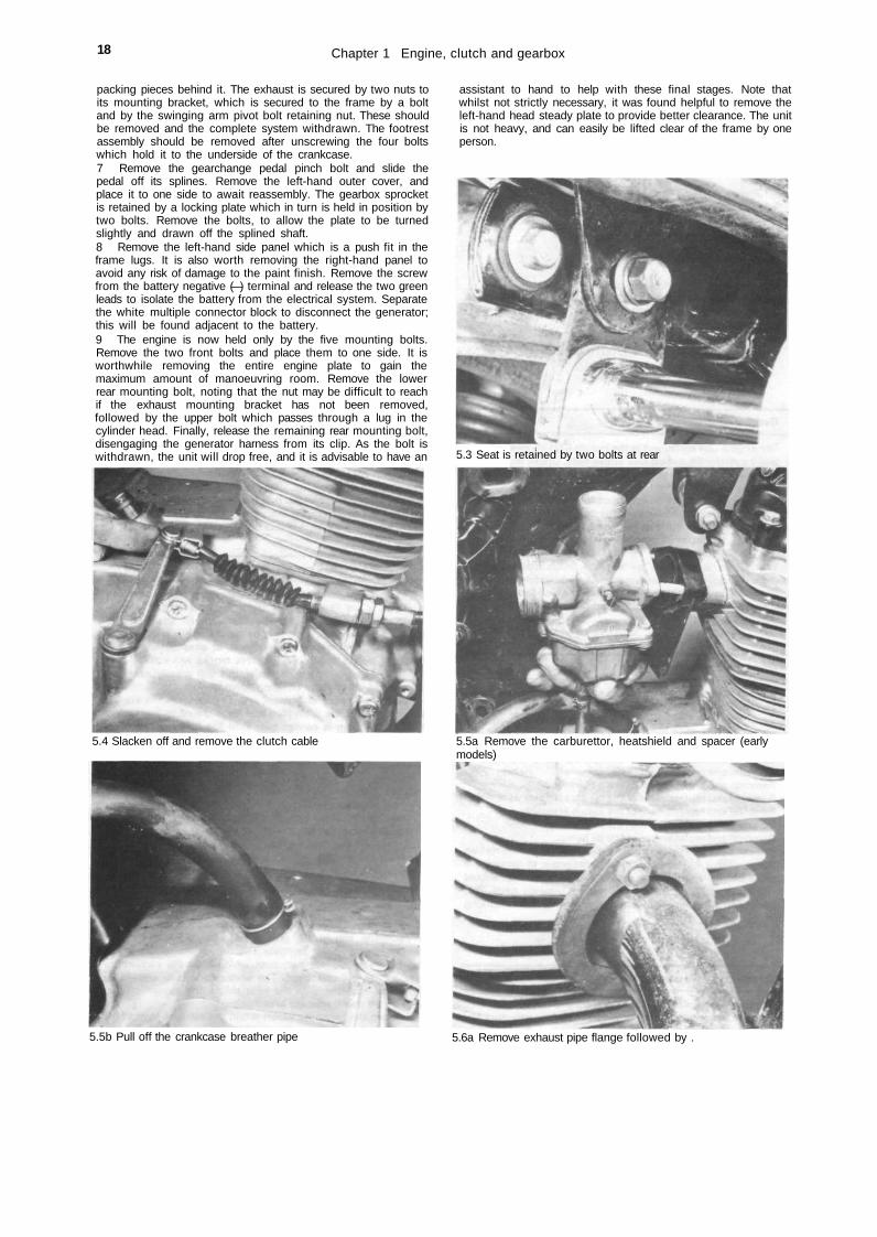
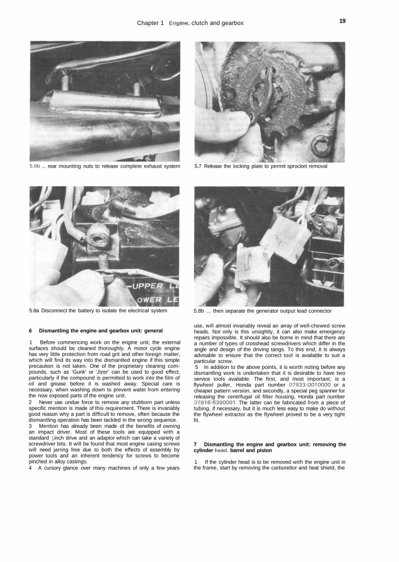
1 Place the machine securely on its centre stand, ensuringthat there is no likelihood of it falling over during engineremoval. Engine removal can be made much easier if themachine is raised about two feet by means of a stand. A stouttable can be modified for this purpose, or alternatively, a fewsubstantial planks and some concrete blocks will suffice. Thisprocedure is by no means essential, but will greatly ease thediscomfort of squatting or kneeling down to work.2 Place a container of at least one litre beneath the engineunit, then remove the drain plug and leave the oil to drain whilefurther dismantling is carried out. Turn the fuel tap to the offposition and prise off the fuel pipe from the stub at the base ofthe tap. A small screwdriver can be used to ease the pipe offwithout straining it.3 Release the seat mounting bolts, which are locatedimmediately above the rear indicator lamps, and lift the seataway from the frame. Disengage the rear of the petrol tank fromthe rubber block which retains it. The tank can then be pulledupwards and back to release the front mounting blocks.4 Slacken off the clutch cable adjuster nuts, and release thecable from the actuating arm on the top of the engine casing.Disengage the cable and lodge it clear of the engine. The sparkplug lead should also be detached and placed out of the way onthe top frame tube.5 Unscrew the carburettor top and withdraw the throttlevalve assembly. There is no need to disconnect the cable, butthe assembly should be positioned where it will not getdamaged during engine removal. Disconnect the rubber intakehose, then remove the two nuts which hold the carburettorflange to the cylinder head. The carburettor body should belifted away, together with the heat shield and spacer or inletstub. Pull off the crankcase breather pipe.6 Remove the two nuts which retain the exhaust pipe to thecylinder head, sliding the flange clear and removing the two
18 Chapter 1 Engine, clutch and gearbox
packing pieces behind it. The exhaust is secured by two nuts toits mounting bracket, which is secured to the frame by a boltand by the swinging arm pivot bolt retaining nut. These shouldbe removed and the complete system withdrawn. The footrestassembly should be removed after unscrewing the four boltswhich hold it to the underside of the crankcase.7 Remove the gearchange pedal pinch bolt and slide thepedal off its splines. Remove the left-hand outer cover, andplace it to one side to await reassembly. The gearbox sprocketis retained by a locking plate which in turn is held in position bytwo bolts. Remove the bolts, to allow the plate to be turnedslightly and drawn off the splined shaft.8 Remove the left-hand side panel which is a push fit in theframe lugs. It is also worth removing the right-hand panel toavoid any risk of damage to the paint finish. Remove the screwfrom the battery negative (—) terminal and release the two greenleads to isolate the battery from the electrical system. Separatethe white multiple connector block to disconnect the generator;this will be found adjacent to the battery.9 The engine is now held only by the five mounting bolts.Remove the two front bolts and place them to one side. It isworthwhile removing the entire engine plate to gain themaximum amount of manoeuvring room. Remove the lowerrear mounting bolt, noting that the nut may be difficult to reachif the exhaust mounting bracket has not been removed,followed by the upper bolt which passes through a lug in thecylinder head. Finally, release the remaining rear mounting bolt,disengaging the generator harness from its clip. As the bolt iswithdrawn, the unit will drop free, and it is advisable to have an
5.4 Slacken off and remove the clutch cable
assistant to hand to help with these final stages. Note thatwhilst not strictly necessary, it was found helpful to remove theleft-hand head steady plate to provide better clearance. The unitis not heavy, and can easily be lifted clear of the frame by oneperson.
5.3 Seat is retained by two bolts at rear
5.5a Remove the carburettor, heatshield and spacer (earlymodels)
5.5b Pull off the crankcase breather pipe 5.6a Remove exhaust pipe flange followed by .
Chapter 1 Engine, clutch and gearbox 19
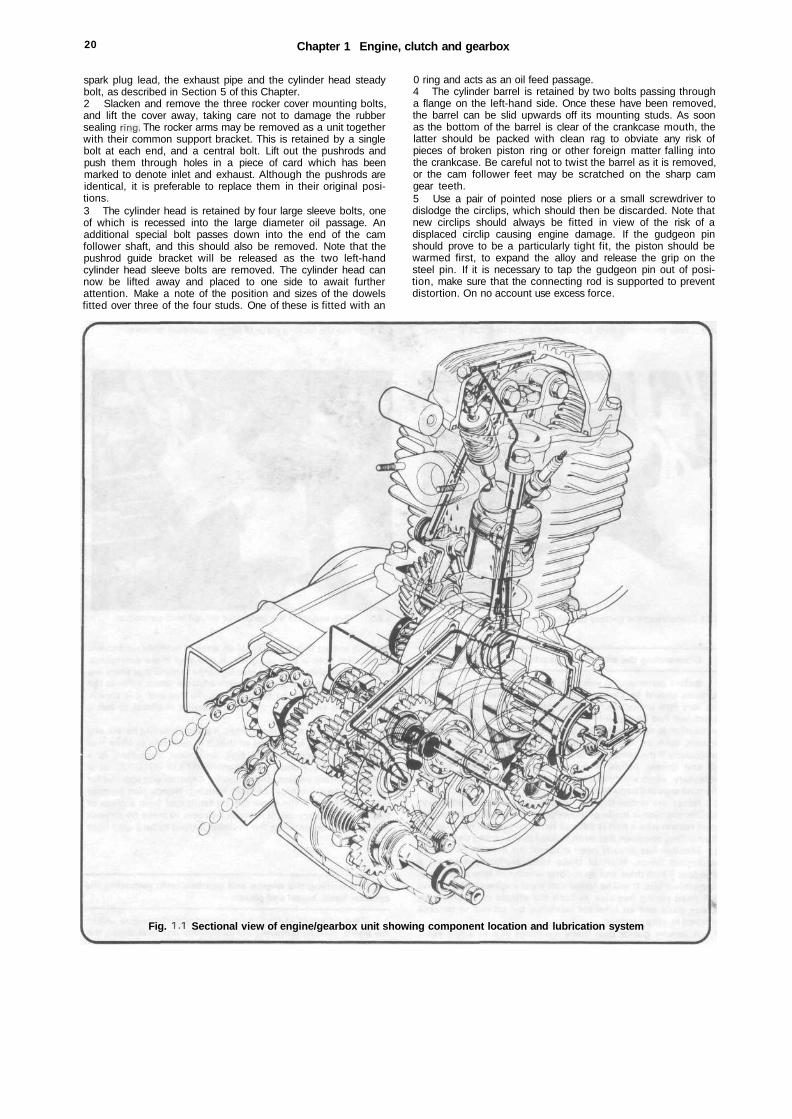
5.6b ... rear mounting nuts to release complete exhaust system 5.7 Release the locking plate to permit sprocket removal
5.8a Disconnect the battery to isolate the electrical system
6 Dismantling the engine and gearbox unit: general
1 Before commencing work on the engine unit, the externalsurfaces should be cleaned thoroughly. A motor cycle enginehas very little protection from road grit and other foreign matter,which will find its way into the dismantled engine if this simpleprecaution is not taken. One of the proprietary cleaning com-pounds, such as 'Gunk' or 'Jizer' can be used to good effect,particularly if the compound is permitted to work into the film ofoil and grease before it is washed away. Special care isnecessary, when washing down to prevent water from enteringthe now exposed parts of the engine unit.2 Never use undue force to remove any stubborn part unlessspecific mention is made of this requirement. There is invariablygood reason why a part is difficult to remove, often because thedismantling operation has been tackled in the wrong sequence.3 Mention has already been made of the benefits of owningan impact driver. Most of these tools are equipped with astandard \ inch drive and an adaptor which can take a variety ofscrewdriver bits. It will be found that most engine casing screwswill need jarring free due to both the effects of assembly bypower tools and an inherent tendency for screws to becomepinched in alloy castings.4 A cursory glance over many machines of only a few years
5.8b ... then separate the generator output lead connector
use, will almost invariably reveal an array of well-chewed screwheads. Not only is this unsightly, it can also make emergencyrepairs impossible. It should also be borne in mind that there area number of types of crosshead screwdrivers which differ in theangle and design of the driving tangs. To this end, it is alwaysadvisable to ensure that the correct tool is available to suit aparticular screw.5 In addition to the above points, it is worth noting before anydismantling work is undertaken that it is desirable to have twoservice tools available. The first, and most important, is aflywheel puller, Honda part number 07933-0010000 or acheaper pattern version, and secondly, a special peg spanner forreleasing the centrifugal oil filter housing, Honda part number07916-6390001. The latter can be fabricated from a piece oftubing, if necessary, but it is much less easy to make do withoutthe flywheel extractor as the flywheel proved to be a very tightfit.
7 Dismantling the engine and gearbox unit: removing thecylinder head, barrel and piston
1 If the cylinder head is to be removed with the engine unit inthe frame, start by removing the carburettor and heat shield, the
20 Chapter 1 Engine, clutch and gearbox
spark plug lead, the exhaust pipe and the cylinder head steadybolt, as described in Section 5 of this Chapter.2 Slacken and remove the three rocker cover mounting bolts,and lift the cover away, taking care not to damage the rubbersealing ring. The rocker arms may be removed as a unit togetherwith their common support bracket. This is retained by a singlebolt at each end, and a central bolt. Lift out the pushrods andpush them through holes in a piece of card which has beenmarked to denote inlet and exhaust. Although the pushrods areidentical, it is preferable to replace them in their original posi-tions.3 The cylinder head is retained by four large sleeve bolts, oneof which is recessed into the large diameter oil passage. Anadditional special bolt passes down into the end of the camfollower shaft, and this should also be removed. Note that thepushrod guide bracket will be released as the two left-handcylinder head sleeve bolts are removed. The cylinder head cannow be lifted away and placed to one side to await furtherattention. Make a note of the position and sizes of the dowelsfitted over three of the four studs. One of these is fitted with an
0 ring and acts as an oil feed passage.4 The cylinder barrel is retained by two bolts passing througha flange on the left-hand side. Once these have been removed,the barrel can be slid upwards off its mounting studs. As soonas the bottom of the barrel is clear of the crankcase mouth, thelatter should be packed with clean rag to obviate any risk ofpieces of broken piston ring or other foreign matter falling intothe crankcase. Be careful not to twist the barrel as it is removed,or the cam follower feet may be scratched on the sharp camgear teeth.5 Use a pair of pointed nose pliers or a small screwdriver todislodge the circlips, which should then be discarded. Note thatnew circlips should always be fitted in view of the risk of adisplaced circlip causing engine damage. If the gudgeon pinshould prove to be a particularly tight fit, the piston should bewarmed first, to expand the alloy and release the grip on thesteel pin. If it is necessary to tap the gudgeon pin out of posi-tion, make sure that the connecting rod is supported to preventdistortion. On no account use excess force.
Fig. 1.1 Sectional view of engine/gearbox unit showing component location and lubrication system
21
24
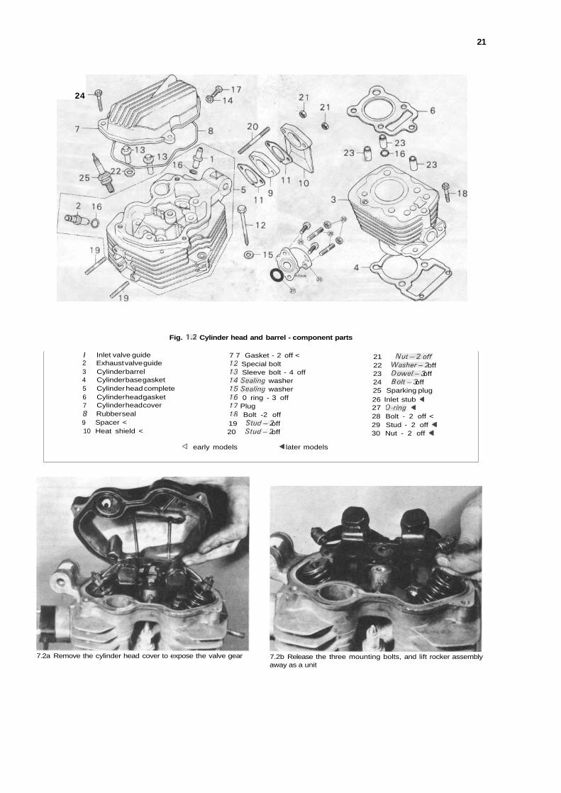
Fig. 1.2 Cylinder head and barrel - component parts
/2345678910
Inlet valve guideExhaust valve guideCylinder barrelCylinder base gasketCylinder head completeCylinder head gasketCylinder head coverRubber sealSpacer <Heat shield <
7 7 Gasket - 2 off <12 Special bolt13 Sleeve bolt - 4 off14 Sea/ing washer15 Sea/ing washer16 0 ring - 3 off17 Plug18 Bolt -2 off19 Stud-2 off20 Stud-2 off
<\ early models ^ later models
21 Nut-2off22 Washer-2 off23 Dowel-3 off24 Bolt-3 off25 Sparking plug26 Inlet stub -427 O-ring <28 Bolt - 2 off <29 Stud - 2 off <30 Nut - 2 off <
7.2a Remove the cylinder head cover to expose the valve gear 7.2b Release the three mounting bolts, and lift rocker assemblyaway as a unit
r
22 Chapter 1 Engine, clutch and gearbox
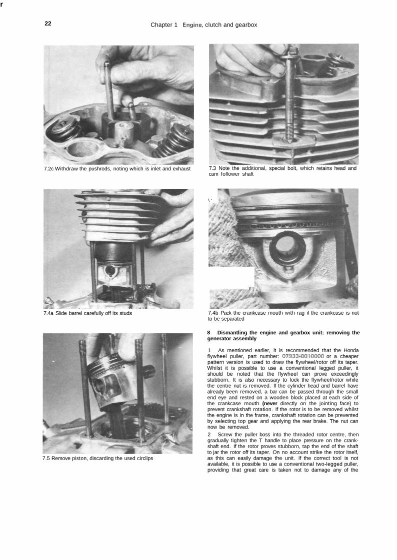
7.2c Withdraw the pushrods, noting which is inlet and exhaust
7.4a Slide barrel carefully off its studs
7.3 Note the additional, special bolt, which retains head andcam follower shaft
\ '
7.5 Remove piston, discarding the used circlips
7.4b Pack the crankcase mouth with rag if the crankcase is notto be separated
8 Dismantling the engine and gearbox unit: removing thegenerator assembly
1 As mentioned earlier, it is recommended that the Hondaflywheel puller, part number: 07933-0010000 or a cheaperpattern version is used to draw the flywheel/rotor off its taper.Whilst it is possible to use a conventional legged puller, itshould be noted that the flywheel can prove exceedinglystubborn. It is also necessary to lock the flywheel/rotor whilethe centre nut is removed. If the cylinder head and barrel havealready been removed, a bar can be passed through the smallend eye and rested on a wooden block placed at each side ofthe crankcase mouth (never directly on the jointing face) toprevent crankshaft rotation. If the rotor is to be removed whilstthe engine is in the frame, crankshaft rotation can be preventedby selecting top gear and applying the rear brake. The nut cannow be removed.2 Screw the puller boss into the threaded rotor centre, thengradually tighten the T handle to place pressure on the crank-shaft end. If the rotor proves stubborn, tap the end of the shaftto jar the rotor off its taper. On no account strike the rotor itself,as this can easily damage the unit. If the correct tool is notavailable, it is possible to use a conventional two-legged puller,providing that great care is taken not to damage any of the
Chapter 1 Engine, clutch and gearbox 23
generator components. The central retaining nut should betemporarily refitted so that it is flush with the shaft end. Do notplace undue strain on the assembly using this method. Ifremoval proves difficult, abandon the attempt and obtain theproper service tool.3 With the flywheel/rotor removed as described above,release the three countersunk screws which secure thegenerator stator. It will also be necessary to release the outputleads from beneath the guide before lifting the assembly clear.There is no need to mark the stator position as this is not vari-able.
9 Dismantling the engine/gearbox unit: removing the camgear and shaft
1 If this job is being tackled with the engine in the frame, it isfirst necessary to remove the cylinder head and pushrods, thecylinder barrel and cam followers and the generator assembly.Refer to the preceding Sections in this Chapter for details.2 The cam gear takes the form of a skew-cut gear driven bythe crankshaft and producing rotation at half engine speed. Thecam lobe is retained on the gear by a circlip, and the assemblyruns on a special shaft which is retained by the generator stator.When the latter is removed, the small thrust spring in the end ofthe shaft will probably fall away. A screwdriver can be used tolever the head of the shaft gently outwards against theresistance of the 0 ring seal. The gear and cam assembly will befreed as the shaft is withdrawn, and can be lifted out throughthe aperture adjacent to the crankcase mouth.
10 Dismantling the engine/gearbox unit: removing thecentrifugal oil filter
1 If the engine is in the frame the oil must be drained, theclutch cable must be disconnected and the exhaust system andfootrest assembly must be removed first. Remove its pinch boltand pull the kickstart pedal off its shaft, then remove all thescrews around the outer edge of the crankcase right-hand
cover. Tap the cover smartly with a soft-faced mallet to breakthe seal and withdraw the cover, noting the two locating dowelsin the mating surface, also the pushrod in the centre of theclutch. Peel off the cover gasket.2 Slacken and remove the three screws which secure the oilfilter cover. As the cover is lifted away, place some rag beneaththe unit to catch the residual oil which will be caught inside thefilter assembly.3 The inner half of the filter housing is retained by a slottednut which will require the use of a peg spanner to release it. Thistool is available as a Honda service tool, part number:07916-6390001. If this is not available, it is possible tofabricate a suitable tool from a length of thick-walled tubing.Refer to the accompanying photograph for details, cutting awaythe segments shown with a hacksaw to leave four tangs. If themachine is to be regarded as a long term purchase, it may beconsidered worthwhile spending some time with a file to obtaina good fit. The end can then be heated to a cherry red colourand quenched in oil to harden the tangs. An axial hole can bedrilled to accept a tommy bar.4 Lock the crankshaft either by selecting top gear andapplying the rear brake (engine in frame) or by passing a barthrough the small end eye and resting the ends on a woodenblock placed each side of the crankcase mouth. The securingnut can then be removed, and the inner housing pulled off thecrankshaft. Note that the special washer, fitted behind the nut,is marked outside' for reference during reassembly.
11 Dismantling the engine/gearbox unit: removing the oilpump
1 The oil pump is retained by two screws which pass throughthe inner pinion casing into the crankcase. It will be noted thatthe front half of the pinion casing has two holes in it. Ascrewdriver can be passed through these, and the correspond-ing holes in the pinion in order to release the retaining screw.The pump can then be lifted away as an assembly.
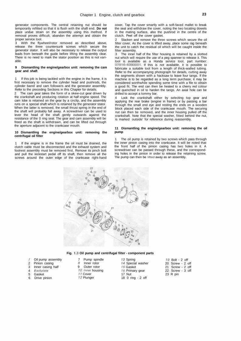
Fig. 1.3 Oil pump and centrifugal filter - component parts
/ Oil pump assembly2 Pinion casing3 Inner casing half4 Backplate5 Gasket6 Drive pinion
7 Pump spindle8 Inner rotor9 Outer rotor10 Inner housing11 Cover12 Plunger
13 Spring14 Special washer15 Gasket16 Primary gear17 Nut18 0 ring - 2 off
19 Bolt - 2 off20 Screw - 2 off21 Screw - 2 off22 Screw - 3 off23 R pin
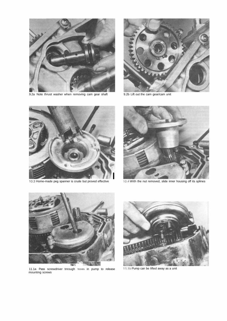
9.2a Note thrust washer when removing cam gear shaft 9.2b Lift out the cam gear/cam unit
I10.3 Home-made peg spanner is crude but proved effective 10.4 With the nut removed, slide inner housing off its splines
mi ^&W11.1a Pass screwdriver tnrough holes in pump to releasemounting screws
11.1b Pump can be lifted away as a unit
Chapter 1 Engine, clutch and gearbox 25
12 Dismantling the engine/gearboxclutch assembly and crankshaft pinion
unit: removing the
1 Lift out the clutch pushrod together with the cup in which itseats, then remove the four bolts which secure the clutchthrust plate, unscrewing them in a diagonal sequence until theclutch spring pressure is released. Lift off the thrust plate andthe four clutch springs and place them to one side.2 Remove the circlip which retains the outer half of the clutchcentre, then remove it, followed by the clutch plain and frictionplates. The inner half of the clutch centre can now be lifted outfollowed by the clutch drum, noting the special thrust washerinterposed between the two. The crankshaft pinion can simplybe slid off its splines once the filter has been removed.
13 Dismantling the engine/gearboxgearchange shaft and mechanism
unit: removing the
1 The gearchange shaft runs in a bore through the crankcase,emerging on the left-hand side of the engine. The complete unitcan be withdrawn from the right-hand side of the unit, thequadrant centring spring disengaging from its locating lug.2 Unscrew the detent roller arm retaining bolt and carefullyrelease the detent spring pressure before withdrawing the bolt,arm and spring. Note how the arm rotates against springpressure on the shouldered portion of the bolt's shank. Removethe camplate retaining bolt from the end of the selector drumand withdraw the camplate, noting that it is located by a smallpin which should be removed to prevent its loss.
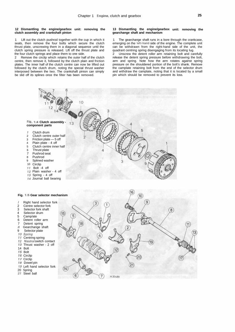
Fig . 1.4 Clutch assembly -component parts
;2345678910
Clutch drumClutch centre outer halfFriction plate — 5 offPlain plate - 4 offClutch centre inner halfThrust platePushrod seatPushrodSplined washerCirclip
11 Bolt -4 off12 Plain washer - 4 off13 Spring - 4 off14 Journal ball bearing
Fig. 1.5 Gear selector mechanism
/ Right hand selector fork2 Centre selector fork3 Selector fork shaft4 Selector drum5 Camp/ate6 Detent roller arm7 Detent spring8 Gearchange shaft9 Selector plate10 Spring11 Centring spring12 Neutral switch contact13 Thrust washer - 2 off14 Bolt15 Bolt16 Circlip17 Circlip18 Dowel pin19 Left hand selector fork20 Spring21 Steel ball
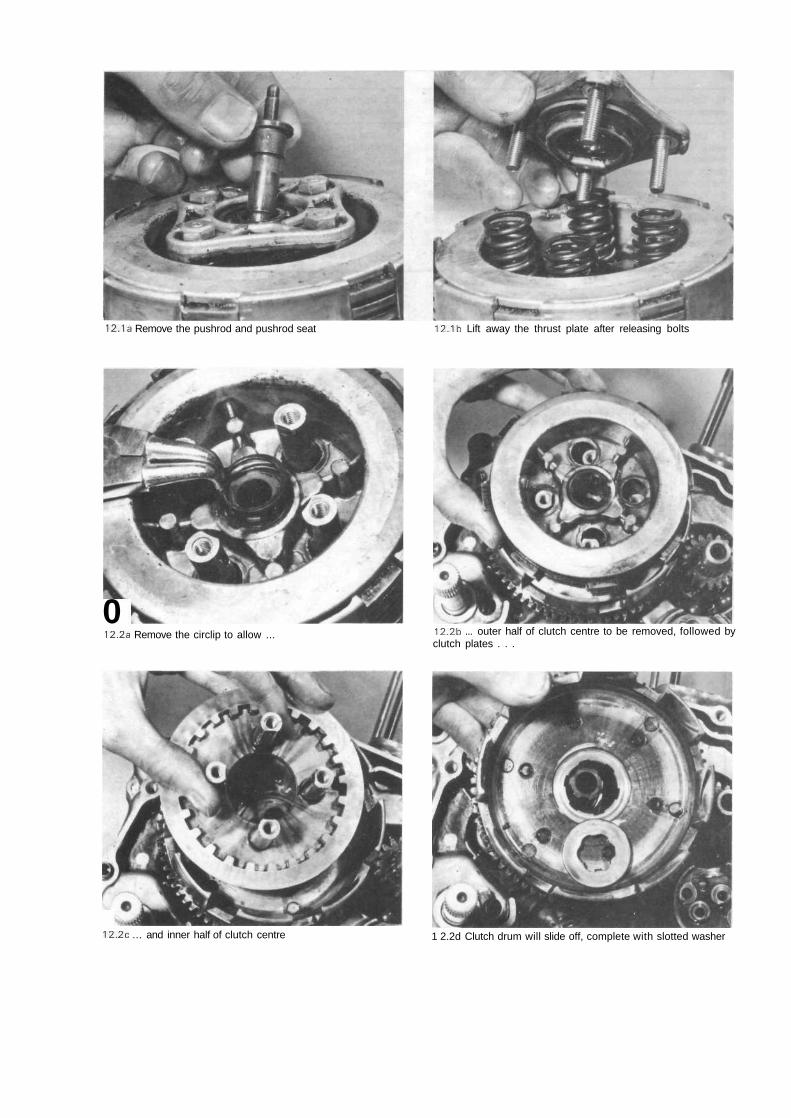
12.1a Remove the pushrod and pushrod seat 12.1b Lift away the thrust plate after releasing bolts
012.2a Remove the circlip to allow ... 12.2b ... outer half of clutch centre to be removed, followed by
clutch plates . . .
12.2c ... and inner half of clutch centre 1 2.2d Clutch drum will slide off, complete with slotted washer
Chapter 1 Engine, clutch and gearbox 27
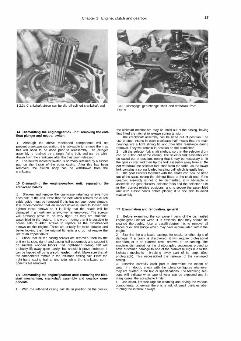
1 2.2e Crankshaft pinion can be slid off splined crankshaft end 13.1 Disengage gearchange shaft and withdraw fromcasing
14 Dismantling the engine/gearbox unit: removing the end-float plunger and neutral switch
1 Although the above mentioned components will notprevent crankcase separation, it is advisable to remove them asthis will need to be done prior to reassembly. The plungerassembly is retained by a single fixing bolt, and can be with*drawn from the crankcase after this has been released.2 The neutral indicator switch is normally retained by a rubberpad on the inside of the outer casing. After this has beenremoved, the switch body can be withdrawn from thecrankcase.
15 Dismantling the engine/gearbox unit: separating thecrankcase halves
1 Slacken and remove the crankcase retaining screws fromeach side of the unit. Note that the bolt which retains the clutchcable guide must be removed if this has not been done already.It is recommended that an impact driver is used to loosen andtighten these screws as it is likely that the heads will bedamaged if an ordinary screwdriver is employed. The screwswill probably prove to be very tight, as they are machine-assembled in the factory. It is worth noting that it is possible toobtain sets of Allen screws to replace all the crossheadedscrews on the engine. These are usually far more durable andbetter looking then the original fitments and do not require theuse of an impact driver.2 Check that all the casing screws are removed, then lay theunit on its side, right-hand casing half uppermost, and support iton suitable wooden blocks. The right-hand casing half willprobably lift away quite easily, but should it prove stubborn itcan be tapped off using a soft headed mallet. Make sure that allthe components remain in the left-hand casing half. Place theright-hand casing half to one side while the crankcase com-ponents are removed.
1 6 Dismantling the engine/gearbox unit: removing the kick-start mechanism, crankshaft assembly and gearbox com-ponents
1 With the left-hand casing half still in position on the blocks,
the kickstart mechanism may be lifted out of the casing, havingfirst lifted the ratchet to release spring tension.
The crankshaft assembly can be lifted out of position. Theuse of steel inserts in each crankcase half means that the mainbearings are a light sliding fit, and offer little resistance duringremoval. They will remain in position on the crankshaft.2 Lift the selector fork shaft slightly, so that the selector drumcan be pulled out of the casing. The selector fork assembly canbe eased out of position, noting that it may be necessary to liftthe gear cluster and then tip the fork assembly away from it. Donot withdraw the selector fork shaft from the forks, as the lowerfork contains a spring loaded locating ball which is easily lost.3 The gear clusters together with the shafts can now be liftedout of the case, noting the shim(s) fitted to the shaft end. If thegearbox assembly is not to be dismantled, it is advisable toassemble the gear clusters, selector forks and the selector drumin their correct relative positions, and to secure the assembledunit with elastic bands before placing it to one side to awaitreassembly.
17 Examination and renovation: general
1 Before examining the component parts of the dismantledengine/gear unit for wear, it is essential that they should becleaned thoroughly. Use a paraffin/petrol mix to remove alltraces of oil and sludge which may have accumulated within theengine.2 Examine the crankcase castings for cracks or other signs ofdamage. If a crack is discovered, it will require professionalattention, or in an extreme case, renewal of the casting. Themachine dismantled for the photographic sequences proved tohave sustained damage to one of the crankcase lugs due to thekickstart mechanism breaking away part of its stop. (Seephotograph). This necessitated the renewal of the damagedcasing.3 Examine carefully each part to determine the extent ofwear. If in doubt, check with the tolerance figures wheneverthey are quoted in the text or specifications. The following sec-tions will indicate what type of wear can be expected and inmany cases, the acceptable limits.4 Use clean, lint-free rags for cleaning and drying the variouscomponents, otherwise there is a risk of small particles obs-tructing the internal oilways.
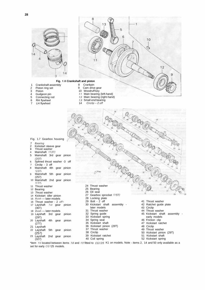
28
Fig. 1.6 Crankshaft and piston1 Crankshaft assembly2 Piston ring set3 Piston4 Gudgeon pin5 Connecting rod6 RH flywheel7 LH flywheel
8 Crankpin9 Cam drive gear10 Woodruff key11 Main bearing (left-hand)12 Main bearing (right-hand)13 Small end bearing14 Circlip-2off
Fig. 1.7 Gearbox housing
72345
678
9
10
11121314151617
1819
20
2122
23
BearingKickstart sleeve gearThrust washerMainshaft (13T)Mainshaft 3rd gear(207)Splined thrust washerCirclip - 3 offMainshaft 4th gear(237)Mainshaft 5th gear(257)Mainshaft 2nd gear(177)Thrust washerBearing7hrust washerKickstart idler pinionBush — later modelsThrust washer - 2 offLayshaft 1st gear(36T)Bush — later modelsLayshaft 3rd gear(29T)Layshaft 4th gear(27T)LayshaftLayshaft 5th gear(257)Layshaft 2nd gear(327)
pinion
-3 off
pinion
pinion
pinion
*pinion
pinion
pinion
pinion
pinion
*item 16 located between items 18 and 19 fitted to CG125set for early CGI 25 models.
24 Thrust washer25 Bearing26 Oil seal27 Gearbox sprocket (15T)28 Locking plate29 Bolt - 2 off30 Kickstart shaft assembly -
later models31 Thrust washer32 Spring guide33 Kickstart spring34 Spring seat35 Kickstart shaft36 Kickstart pinion (29T)37 Thrust washer38 Circlip39 Kickstart ratchet40 Coil spring
K1 on models. Note
41 Thrust washer42 Ratchet guide plate43 Circlip44 Thrust washer45 Kickstart shaft assembly -
early models46 Friction clip47 Kickstart ratchet48 Circlip49 Thrust washer50 Kickstart pinion (29T)51 Kickstart shaft52 Kickstart spring
- items 2, 14 and 50 only available as a
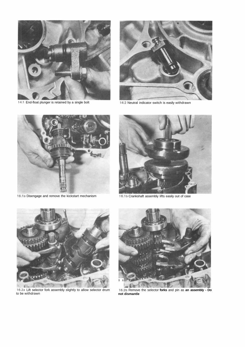
14.1 End-float plunger is retained by a single bolt 14.2 Neutral indicator switch is easily withdrawn
16.1a Disengage and remove the kickstart mechanism 16.1b Crankshaft assembly lifts easily out of case
16.2a Lift selector fork assembly slightly to allow selector drumto be withdrawn
I 1
16.2b Remove the selector forks and pin as an assembly - Donot dismantle
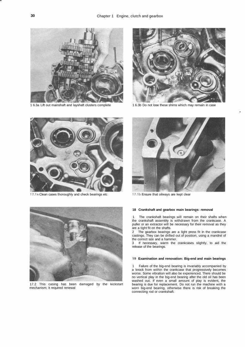
r
30 Chapter 1 Engine, clutch and gearbox
1 6.3a Lift out mainshaft and layshaft clusters complete
17.1a Clean cases thoroughly and check bearings etc
17.2 This casing has been damaged by the kickstartmechanism; it required renewal
1 6.3b Do not lose these shims which may remain in case
•
17.1b Ensure that oilways are kept clear
18 Crankshaft and gearbox main bearings: removal
1 The crankshaft bearings will remain on their shafts whenthe crankshaft assembly is withdrawn from the crankcase. Apuller or an extractor will be necessary for their removal as theyare a tight fit on the shafts.2 The gearbox bearings are a light press fit in the crankcasecastings. They can be drifted out of position, using a mandrel ofthe correct size and a hammer.3 If necessary, warm the crankcases slightly, to aid therelease of the bearings.
19 Examination and renovation: Big-end and main bearings
1 Failure of the big-end bearing is invariably accompanied bya knock from within the crankcase that progressively becomesworse. Some vibration will also be experienced. There should beno vertical play in the big-end bearing after the old oil has beenwashed out. If even a small amount of play is evident, thebearing is due for replacement. Do not run the machine with aworn big-end bearing, otherwise there is risk of breaking theconnecting rod or crankshaft.

Chapter 1 Engine, clutch and gearbox 31
A certain amount of side play is intentional, and should bebetween 0-05 - 0-30 mm (0-002 - 0 0 1 2 in) on a new crank-shaft. The maximum allowable side play is 0-80 mm (0032 in)and can be checked with a feeler gauge between the flywheelface and the edge of the connecting rod.2 It is not possible to separate the flywheel assembly in orderto replace the bearing because the parallel sided crankpin ispressed into the flywheels. Big-end repair should be entrustedto a Honda agent, who will have the necessary repair orreplacement facilities.3 Failure of the main bearings is usually evident in the form ofan audible rumble from the bottom end of the engine,accompanied by vibration. The vibration will be most noticeablethrough the footrests.4 The crankshaft main bearings are of the journal ball type. Ifwear is evident in the form of play or if the bearings feel roughas they are rotated, replacement is necessary. To remove themain bearings if the appropriate service tool is not available,insert two thin steel wedges, one on each side of the bearing,and with these clamped in a vice hit the end of the crankshaftsquarely with a rawhide mallet in an attempt to drive the crank-shaft through the bearing. When the bearing has moved theinitial amount, it should be possible to insert a conventional twoor three legged sprocket puller, to complete the drawing-offaction.
18.1a Use steel wedges and a puller to remove worn mainbearings
/i18.1b Mark pinion relative to shaft before withdrawing pinion 18.2 Bearings can be tapped out of the cases using large drift
20 Examination and renovation: gudgeon pin, small end andpiston bosses
1 The fit of the gudgeon pin in both the small end eye of theconnecting rod, and in the piston bosses should be checked. Inthe case of the small end eye, slide the pin into position andcheck for wear by moving the pin up and down. The pin shouldbe a light sliding fit with no discernible radial play. If play isdetected, it will almost certainly be the small end eye which hasworn rather than the gudgeon pin, although in extreme cases,the latter may also have become worn. The connecting rod isnot fitted with a bush type of small end bearing, and conse-quently a new connecting rod will have to be fitted if worn. Thisis not a simple job, as the flywheels must be parted to fit thenew component, and is a job for a Honda Service Agent. Itshould be borne in mind that if the small end has worn, it islikely that the big-end bearing will require attention.2 Check the fit of the gudgeon pin in the piston. This is nor-mally a fairly tight fit, and it is not unusual for the piston to haveto be warmed slightly to allow the pin to be inserted andremoved. After considerable mileages have been covered, it ispossible that the bosses will have become enlarged. If thisproves to be the case, it will be necessary to renew the piston toeffect a cure. It is worth noting, as an aid to diagnosis, that wear
in the above areas is characterised by a metallic rattle when theengine is running.
21 Examination and renovation: piston and piston rings
1 If a rebore is necessary, the existing piston and rings can bedisregarded because they will be replaced with their oversizeequivalents as a matter of course.2 Remove all traces of carbon from the piston crown, using asoft scraper to ensure the surface is not marked. Finish off bypolishing the crown, with metal polish, so that carbon does notadhere so easily in the future. Never use emery cloth.3 Piston wear usually occurs at the skirt or lower end of thepiston and takes the form of vertical streaks or score marks onthe thrust side. There may also be some variation in thethickness of the skirt. Measure the piston skirt outside diameterat right angles to the gudgeon pin axis and at a point 10 mm(0.4 in) above the base of the skirt; renew the piston if it isfound to be scored, damaged or worn to the specified wear limitor beyond.4 The piston ring grooves may also become enlarged in use,allowing the piston rings to have greater side float. If theclearance exceeds 0-10 mm (0004 in) for the two compressionrings, the piston is due for renewal. It is unusual for this amountof wear to occur on its own.
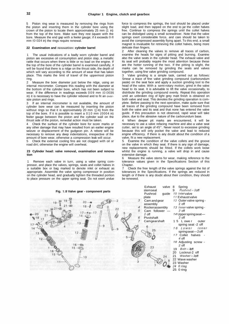
32 Chapter 1 Engine, clutch and gearbox
5 Piston ring wear is measured by removing the rings fromthe piston and inserting them in the cylinder bore using thecrown of the piston to locate them approximately 25 mm (1 in)from the top of the bore. Make sure they rest square with thebore. Measure the end gap with a feeler gauge; if it exceeds 0-6mm (0-024 in) the rings require renewal.
22 Examination and renovation: cylinder barrel
1 The usual indications of a badly worn cylinder barrel andpiston are excessive oil consumption and piston slap, a metallicrattle that occurs when there is little or no load on the engine. Ifthe top of the bore of the cylinder barrel is examined carefully, itwill be found that there is a ridge on the thrust side, the depth ofwhich will vary according to the amount of wear that has takenplace. This marks the limit of travel of the uppermost pistonring.2 Measure the bore diameter just below the ridge, using aninternal micrometer. Compare this reading with the diameter atthe bottom of the cylinder bore, which has not been subject towear. If the difference in readings exceeds 0 0 9 mm (0-0035in) it is necessary to have the cylinder rebored and to fit an over-size piston and rings.3 If an internal micrometer is not available, the amount ofcylinder bore wear can be measured by inserting the pistonwithout rings so that it is approximately 20 mm (f in) from thetop of the bore. If it is possible to insert a 0 1 0 mm (0004 in)feeler gauge between the piston and the cylinder wall on thethrust side of the piston, remedial action must be taken.4 Check the surface of the cylinder bore for score marks orany other damage that may have resulted from an earlier engineseizure or displacement of the gudgeon pin. A rebore will benecessary to remove any deep indentations, irrespective of theamount of bore wear, otherwise a compression leak will occur.5 Check the external cooling fins are not clogged with oil orroad dirt; otherwise the engine will overheat.
23 Cylinder head: valve removal, examination and renova-tion
1 Remove each valve in turn, using a valve spring com-pressor, and place the valves, springs, seats and collet halves ina suitable box or bag marked to denote inlet or exhaust asappropriate. Assemble the valve spring compressor in positionon the cylinder head, and gradually tighten the threaded portionto place pressure on the upper spring seat. Do not exert undue
force to compress the springs, the tool should be placed underslight load, and then tapped on the end to jar the collet halvesfree. Continue to compress the springs until the collet halvescan be dislodged using a small screwdriver. Note that the valvesprings exert considerable force, and care should be taken toavoid the compressed assembly flying apart. To this end, a smallmagnet is invaluable for retrieving the collet halves, being moredelicate than fingers.2 After cleaning the valves to remove all traces of carbon,examine the heads for signs of pitting and burning. Examinealso the valve seats in the cylinder head. The exhaust valve andits seat will probably require the most attention because theseare the hotter running of the two. If the pitting is slight, themarks can be removed by grinding the seats and valvestogether, using fine valve grinding compound.3 Valve grinding is a simple task, carried out as follows:Smear a trace of fine valve grinding compound (carborundumpaste) on the seat face and apply a suction grinding tool to thehead of the valve. With a semi-rotary motion, grind in the valvehead to its seat. It is advisable to lift the valve occasionally, todistribute the grinding compound evenly. Repeat this operationuntil an unbroken ring of light grey matt finish is obtained onboth valve and seat. This denotes the grinding operation is com-plete. Before passing to the next operation, make quite sure thatall traces of the grinding compound have been removed fromboth the valve and its seat and that none has entered the valveguide. If this precaution is not observed, rapid wear will takeplace, due to the abrasive nature of the carborundum base.4 When deeper pit marks are encountered, it will benecessary to use a valve refacing machine and also a valve seatcutter, set to an angle of 45°. Never resort to excessive grindingbecause this will only pocket the valve and lead to reducedengine efficiency. If there is any doubt about the condition of avalve, fit a new replacement.5 Examine the condition of the valve collets and the grooveon the valve in which they seat. If there is any sign of damage,new replacements should be fitted. If the collets work loosewhilst the engine is running, a valve will drop in and causeextensive damage.6 Measure the valve stems for wear, making reference to thetolerance values given in the Specifications Section of thisChapter.7 Check the free length of the valve springs against the list oftolerances in the Specifications. If the springs are reduced inlength or if there is any doubt about their condition, they shouldbe renewed.
Fig. 1.8 Valve gear - component partsExhaust valvestem sealPushrod guideplateCam and gearassemblyRocker assemblyCam follower —2 offPivot shaftCam gear shaft
8 Spring9 Pushrod-2 off10 Inlet valve11 Exhaust valve12 Outer valve spring -
2 off13 Inner valve spring -
2 off14 Upper spring seat —
2 off1 5 L owe r outer
spring seat -2 off16 Lower inner
spring seat — 2 off17 Collet halves -
4 off18 Adjusting screw -
2 off19 Bolt-3 off20 Locknut-2 off21 Washer-3 off22 Wave washer23 Washer24 0 ring25 0 ring
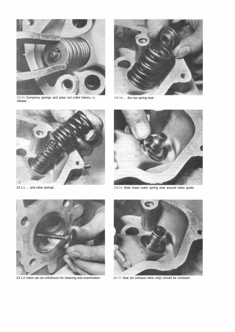
23.1a Compress springs and prise out collet halves, torelease ...
23.1b ... the top spring seat .
23.1 c ... and valve springs 23.1d Note lower outer spring seat around valve guide
23.1 e Valve can be withdrawn for cleaning and examination 23.1f Seal (on exhaust valve only) should be renewed
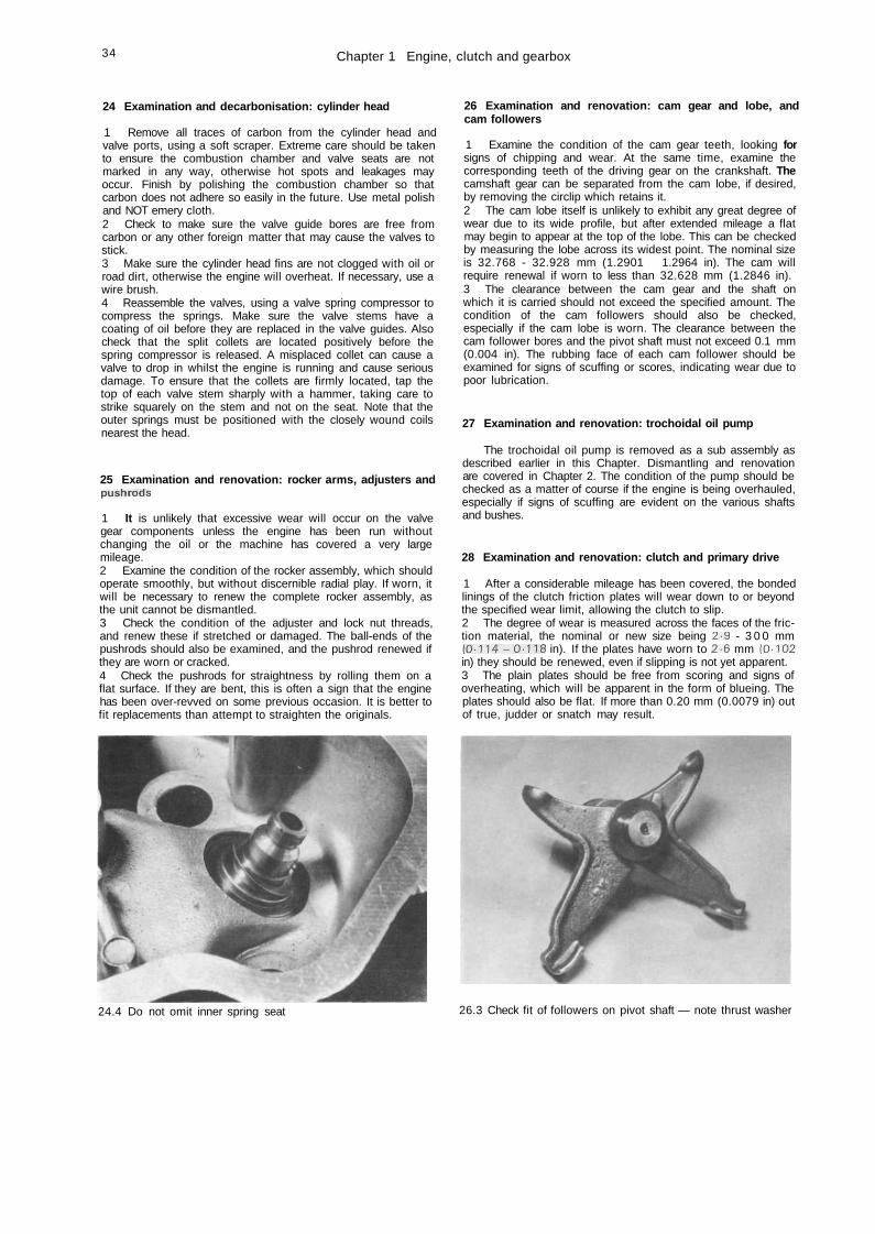
34 Chapter 1 Engine, clutch and gearbox
24 Examination and decarbonisation: cylinder head
1 Remove all traces of carbon from the cylinder head andvalve ports, using a soft scraper. Extreme care should be takento ensure the combustion chamber and valve seats are notmarked in any way, otherwise hot spots and leakages mayoccur. Finish by polishing the combustion chamber so thatcarbon does not adhere so easily in the future. Use metal polishand NOT emery cloth.2 Check to make sure the valve guide bores are free fromcarbon or any other foreign matter that may cause the valves tostick.3 Make sure the cylinder head fins are not clogged with oil orroad dirt, otherwise the engine will overheat. If necessary, use awire brush.4 Reassemble the valves, using a valve spring compressor tocompress the springs. Make sure the valve stems have acoating of oil before they are replaced in the valve guides. Alsocheck that the split collets are located positively before thespring compressor is released. A misplaced collet can cause avalve to drop in whilst the engine is running and cause seriousdamage. To ensure that the collets are firmly located, tap thetop of each valve stem sharply with a hammer, taking care tostrike squarely on the stem and not on the seat. Note that theouter springs must be positioned with the closely wound coilsnearest the head.
25 Examination and renovation: rocker arms, adjusters andpush rods
1 It is unlikely that excessive wear will occur on the valvegear components unless the engine has been run withoutchanging the oil or the machine has covered a very largemileage.2 Examine the condition of the rocker assembly, which shouldoperate smoothly, but without discernible radial play. If worn, itwill be necessary to renew the complete rocker assembly, asthe unit cannot be dismantled.3 Check the condition of the adjuster and lock nut threads,and renew these if stretched or damaged. The ball-ends of thepushrods should also be examined, and the pushrod renewed ifthey are worn or cracked.4 Check the pushrods for straightness by rolling them on aflat surface. If they are bent, this is often a sign that the enginehas been over-revved on some previous occasion. It is better tofit replacements than attempt to straighten the originals.
26 Examination and renovation: cam gear and lobe, andcam followers
1 Examine the condition of the cam gear teeth, looking forsigns of chipping and wear. At the same time, examine thecorresponding teeth of the driving gear on the crankshaft. Thecamshaft gear can be separated from the cam lobe, if desired,by removing the circlip which retains it.2 The cam lobe itself is unlikely to exhibit any great degree ofwear due to its wide profile, but after extended mileage a flatmay begin to appear at the top of the lobe. This can be checkedby measuring the lobe across its widest point. The nominal sizeis 32.768 - 32.928 mm (1.2901 - 1.2964 in). The cam willrequire renewal if worn to less than 32.628 mm (1.2846 in).3 The clearance between the cam gear and the shaft onwhich it is carried should not exceed the specified amount. Thecondition of the cam followers should also be checked,especially if the cam lobe is worn. The clearance between thecam follower bores and the pivot shaft must not exceed 0.1 mm(0.004 in). The rubbing face of each cam follower should beexamined for signs of scuffing or scores, indicating wear due topoor lubrication.
27 Examination and renovation: trochoidal oil pump
The trochoidal oil pump is removed as a sub assembly asdescribed earlier in this Chapter. Dismantling and renovationare covered in Chapter 2. The condition of the pump should bechecked as a matter of course if the engine is being overhauled,especially if signs of scuffing are evident on the various shaftsand bushes.
28 Examination and renovation: clutch and primary drive
1 After a considerable mileage has been covered, the bondedlinings of the clutch friction plates will wear down to or beyondthe specified wear limit, allowing the clutch to slip.2 The degree of wear is measured across the faces of the fric-tion material, the nominal or new size being 2-9 - 3 0 0 mm(0-114-0-118 in). If the plates have worn to 2-6 mm (0102in) they should be renewed, even if slipping is not yet apparent.3 The plain plates should be free from scoring and signs ofoverheating, which will be apparent in the form of blueing. Theplates should also be flat. If more than 0.20 mm (0.0079 in) outof true, judder or snatch may result.
24.4 Do not omit inner spring seat 26.3 Check fit of followers on pivot shaft — note thrust washer

Chapter 1 Engine, clutch and gearbox 35
4 Measure the uncompressed length of the clutch springswhich should be 35.5 mm (1-398 in) when new. Should anyspring have settled to the specified service limit or shorter, allfour springs should be renewed as a set.5 Check the condition of the thrust bearing assembly andpushrod, which are located in the clutch centre. Excessive playor wear will cause noise and erratic operation.6 Check the condition of the slots in the outer surface of theclutch centre and the inner surfaces of the outer drum. In anextreme case, clutch chatter may have caused the tongues ofthe inserted plates to make indentations in the slots of the outerdrum, or the tongues of the plain plates to indent the slots of theclutch centre. These indentations will trap the clutch plates asthey are freed, and impair clutch action. If the damage is onlyslight the indentations can be removed by careful work with afile and the burrs removed from the tongues of the clutch platesin a similar fashion. More extensive damage will necessitaterenewal of the parts concerned.7 The clutch release mechanism attached to the inside of thecrankcase right-hand cover takes the form of a vertical spindlewith a cam on the lower end. A light return spring ensures thatpressure is taken off the end of the pushrod once the handlebarlever has been released. No attention is normally required, otherthan greasing prior to reassembly.8 The primary drive is by means of a crankshaft-mountedgear driving the clutch by way of teeth on the outer drum. Thetwo gears should be examined for signs of wear or chippedteeth, and replaced as necessary, preferably as a pair.
29 Examination and renovation: gearbox components
1 Examine each of the gear pinions to ensure that there areno chipped or broken teeth and that the dogs on the end of thepinions are not rounded. Gear pinions with these defects mustbe renewed; there is no satisfactory method of reclaiming them.2 Examine the selector forks carefully, ensuring that there isno scoring or wear where they engage in the gears, and thatthey are not bent. Damage and wear rarely occur in a gearboxwhich has been properly used and correctly lubricated, unlessvery high mileages have been covered.3 The tracks in the selector drum, which co-ordinate themovement of the selector forks, should not show signs of unduewear. Check also that the detent arm spring has not weakened,and that no play has developed in the gear selector linkages.4 Unless the unit has shown signs of wear or malfunctioning,it is unnecessary to dismantle the kickstart assembly. It ishowever, a very simple unit to deal with.5 Check the movement of the gear on the spiral which bringsit into engagement with the coupling gear. Look for chipped orbroken teeth and excessive wear, replacing the gear ifnecessary.
30 Engine casings and covers: examination and repair
1 The aluminium alloy casings and covers are unlikely tosuffer damage through ordinary use. However, damage canoccur if the machine is dropped, or if sudden mechanicalbreakages occur, such as the rear chain breaking.2 Small cracks or holes may be repaired with an epoxy resinadhesive, such as Araldite, as a temporary expedient. Per-manent repairs can only be effected by argon-arc welding, and aspecialist in this process is in a position to advise on the viabilityof proposed repair. Often it may be cheaper to buy a newreplacement.3 Damaged threads can be economically reclaimed by using adiamond section wire insert, of the Helicoil type, which is easilyfitted after drilling and re-tapping the affected thread. Theprocess is quick and inexpensive, and does not require as muchpreparation and work as the older method of fitting brass, or
similar inserts. Most motorcycle dealers and small engineeringfirms offer a service of this kind.4 Sheared studs or screws can usually be removed withscrew extractors, which consist of tapered, left-hand threadscrews, of very hard steel. These are inserted by screwing anti-clockwise, into a pre-drilled hole in the stud, and usuallysucceed in dislodging the most stubborn stud or screw. The onlyalternative to this is spark erosion, but as this is a very limited,specialised facility, it will probably be unavailable to mostowners. It is wise, however, to consult a professional engineer-ing firm before condemning an otherwise sound casing. Manyof these firms advertise regularly in the motorcycle papers.
31 Engine reassembly: general
1 Before reassembly of the engine/gear unit is commenced,the various component parts should be cleaned thoroughly andpieced on a sheet of clean paper, close to the working area.2 Make sure all traces of old gaskets have been removed andthat the mating surfaces are clean and undamaged. One of thebest ways to remove old gasket cement is to apply a rag soakedin methylated spirit. This acts as a solvent and will ensure thatthe cement is removed without resort to scraping and the con-sequent risk of damage.3 Gather together all the necessary tools and have availablean oil can filled with clean engine oil. Make sure all the newgaskets and oil seals are to hand, also all replacement partsrequired. Nothing is more frustrating than having to stop in themiddle of a reassembly sequence because a vital gasket orreplacement has been overlooked.4 Make sure that the reassembly area is clean and that thereis adequate working space. Many of the smaller bolts are easilysheared if over-tightened. Always use the correct sizescrewdriver bit for the crosshead screws and never an ordinaryscrewdriver or punch. If the existing screws show evidence ofmaltreatment in the past, it is advisable to renew them as acomplete set.5 If the purchase of a replacement set of screws is being con-templated, it is worthwhile considering a set of socket or Allenscrews. These are invariably much more robust than theoriginals, and can be obtained in sets for most machines, ineither black or nickel plated finishes. The manufacturers ofthese screw sets advertise regularly in the motorcycle press.
32 Engine reassembly: gear clusters and selectormechanism reassembly and replacement
1 Having examined and renewed the gearbox components asnecessary, the clusters can be built up and assembled as a com-plete unit for installation in the engine/gearbox casings.2 Study the line drawing carefully (Fig. 1.7) and assemble thelayshaft components in the exact order shown, ensuring thatthe thrust washers and circlips are correctly positioned. Thegearbox mainshaft (input shaft) should be tackled in a similarmanner. See also the accompanying photographic sequence.
33 Engine reassembly: replacing the crankcase components
1 Place the larger, left-hand, crankcase half on blocks on theworkbench, checking that a reasonable amount of room isallowed for the shafts to protrude when fitted. The gearboxmainshaft and layshaft clusters should be placed into positionfirst, ensuring that the shim fitted on the mainshaft end is notomitted. The selector forks, having previously been fitted totheir pivot shaft, can now be placed in position. This operationcalls for a certain amount of patience, as the three forks must beeased into their respective grooves before the pivot shaft willlocate correctly.
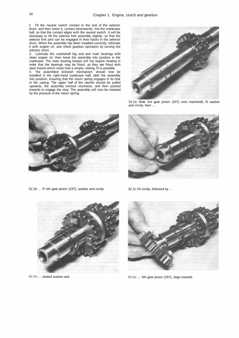
36 Chapter 1 Engine, clutch and gearbox
2 Fit the neutral switch contact to the end of the selectordrum, and then lower it, contact downwards, into the crankcasehalf, so that the contact aligns with the neutral switch. It will benecessary to lift the selector fork assembly slightly, so that theselector fork pins can be engaged in their tracks in the selectordrum. When the assembly has been installed correctly, lubricateit with engine oil, and check gearbox operation by turning theselector drum.3 Lubricate the crankshaft big end and main bearings withclean engine oil, then lower the assembly into position in thecrankcase. The main bearing bosses will not require heating inorder that the bearings may be fitted, as they are fitted withsteel inserts which mean that a simple, sliding, fit is possible.4 The assembled kickstart mechanism should now beinstalled in the right-hand crankcase half; slide the assemblyinto position, ensuring that the return spring engages in its holein the casing. The upper half of the ratchet should be pulledupwards, the assembly twisted clockwise, and then pushedinwards to engage the stop. The assembly will now be retainedby the pressure of the return spring.
32.2a Slide 3rd gear pinion (20T) onto mainshaft, fit washerand circlip, then ...
32.2b ... fit 4th gear pinion (23T), washer and circlip 32.2c Fit circlip, followed by ...
32.2d ... slotted washer and 32.2e ... 5th gear pinion (25T), dogs inwards
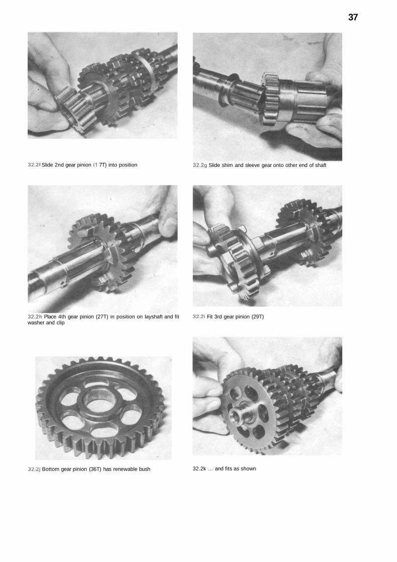
37
32.2f Slide 2nd gear pinion (1 7T) into position 32.2g Slide shim and sleeve gear onto other end of shaft
32.2h Place 4th gear pinion (27T) in position on layshaft and fitwasher and clip
32.2i Fit 3rd gear pinion (29T)
32.2j Bottom gear pinion (36T) has renewable bush 32.2k ... and fits as shown
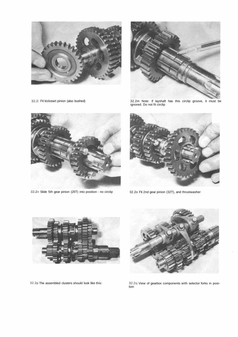
32.21 Fit kickstart pinion (also bushed) 32.2m Note: If layshaft has this circlip groove, it must beignored. Do not fit circlip
32.2n Slide 5th gear pinion (25T) into position - no circlip 32.2o Fit 2nd gear pinion (32T), and thrustwasher
'
32.2p The assembled clusters should look like this: 32.2q View of gearbox components with selector forks in posi-tion
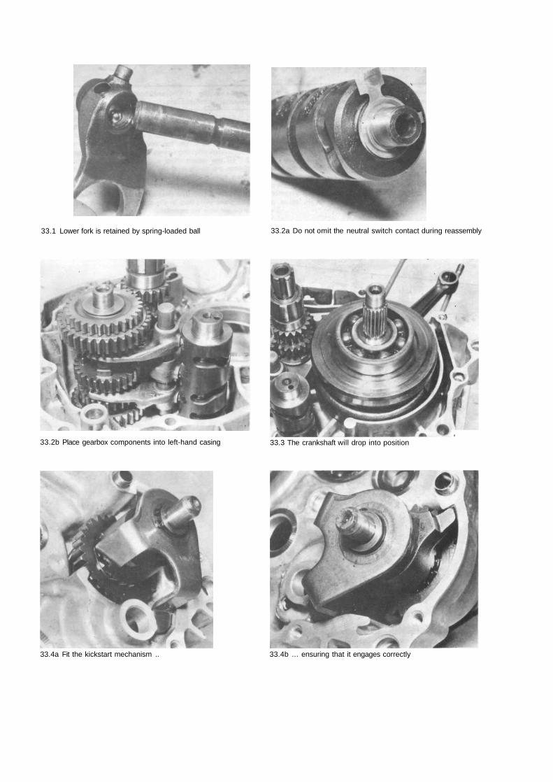
33.1 Lower fork is retained by spring-loaded ball
33.2b Place gearbox components into left-hand casing
33.2a Do not omit the neutral switch contact during reassembly
,33.3 The crankshaft will drop into position
33.4a Fit the kickstart mechanism .. 33.4b ... ensuring that it engages correctly
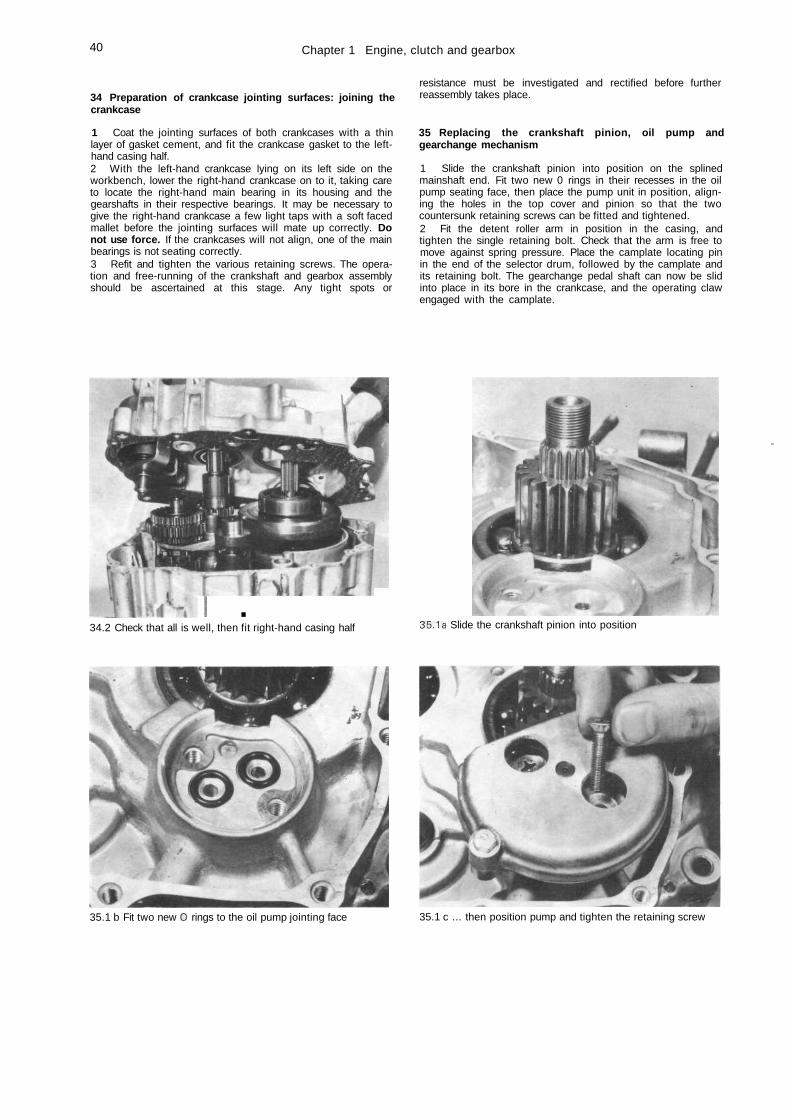
40 Chapter 1 Engine, clutch and gearbox
34 Preparation of crankcase jointing surfaces: joining thecrankcase
1 Coat the jointing surfaces of both crankcases with a thinlayer of gasket cement, and fit the crankcase gasket to the left-hand casing half.2 With the left-hand crankcase lying on its left side on theworkbench, lower the right-hand crankcase on to it, taking careto locate the right-hand main bearing in its housing and thegearshafts in their respective bearings. It may be necessary togive the right-hand crankcase a few light taps with a soft facedmallet before the jointing surfaces will mate up correctly. Donot use force. If the crankcases will not align, one of the mainbearings is not seating correctly.3 Refit and tighten the various retaining screws. The opera-tion and free-running of the crankshaft and gearbox assemblyshould be ascertained at this stage. Any tight spots or
resistance must be investigated and rectified before furtherreassembly takes place.
35 Replacing the crankshaft pinion, oil pump andgearchange mechanism
1 Slide the crankshaft pinion into position on the splinedmainshaft end. Fit two new 0 rings in their recesses in the oilpump seating face, then place the pump unit in position, align-ing the holes in the top cover and pinion so that the twocountersunk retaining screws can be fitted and tightened.2 Fit the detent roller arm in position in the casing, andtighten the single retaining bolt. Check that the arm is free tomove against spring pressure. Place the camplate locating pinin the end of the selector drum, followed by the camplate andits retaining bolt. The gearchange pedal shaft can now be slidinto place in its bore in the crankcase, and the operating clawengaged with the camplate.
I .34.2 Check that all is well, then fit right-hand casing half
'
35.1a Slide the crankshaft pinion into position
35.1 b Fit two new O rings to the oil pump jointing face 35.1 c ... then position pump and tighten the retaining screw
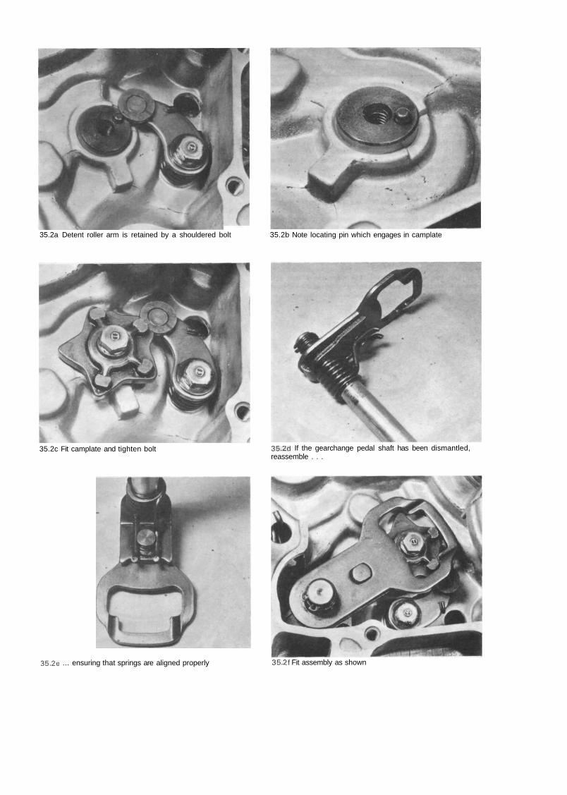
35.2a Detent roller arm is retained by a shouldered bolt 35.2b Note locating pin which engages in camplate
35.2c Fit camplate and tighten bolt 35.2d If the gearchange pedal shaft has been dismantled,reassemble . . .
35.2e ... ensuring that springs are aligned properly 35.2f Fit assembly as shown
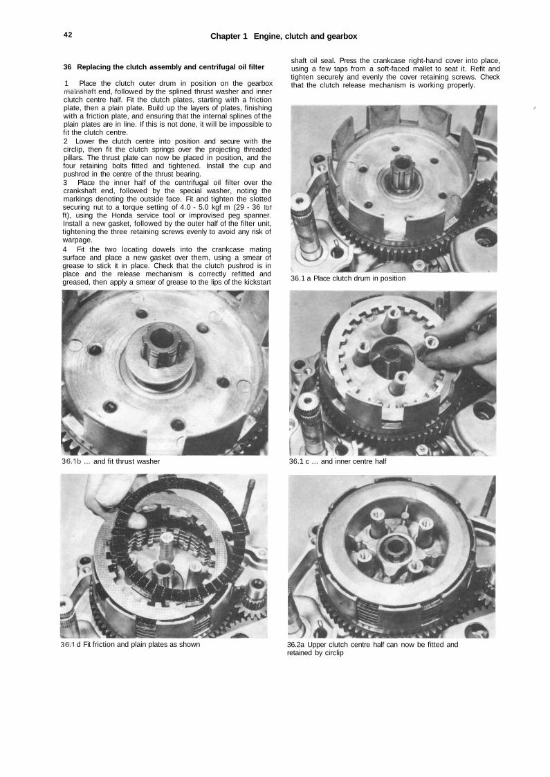
42 Chapter 1 Engine, clutch and gearbox
36 Replacing the clutch assembly and centrifugal oil filter
1 Place the clutch outer drum in position on the gearboxmainshaft end, followed by the splined thrust washer and innerclutch centre half. Fit the clutch plates, starting with a frictionplate, then a plain plate. Build up the layers of plates, finishingwith a friction plate, and ensuring that the internal splines of theplain plates are in line. If this is not done, it will be impossible tofit the clutch centre.2 Lower the clutch centre into position and secure with thecirclip, then fit the clutch springs over the projecting threadedpillars. The thrust plate can now be placed in position, and thefour retaining bolts fitted and tightened. Install the cup andpushrod in the centre of the thrust bearing.3 Place the inner half of the centrifugal oil filter over thecrankshaft end, followed by the special washer, noting themarkings denoting the outside face. Fit and tighten the slottedsecuring nut to a torque setting of 4.0 - 5.0 kgf m (29 - 36 Ibfft), using the Honda service tool or improvised peg spanner.Install a new gasket, followed by the outer half of the filter unit,tightening the three retaining screws evenly to avoid any risk ofwarpage.4 Fit the two locating dowels into the crankcase matingsurface and place a new gasket over them, using a smear ofgrease to stick it in place. Check that the clutch pushrod is inplace and the release mechanism is correctly refitted andgreased, then apply a smear of grease to the lips of the kickstart
36.1b ... and fit thrust washer
shaft oil seal. Press the crankcase right-hand cover into place,using a few taps from a soft-faced mallet to seat it. Refit andtighten securely and evenly the cover retaining screws. Checkthat the clutch release mechanism is working properly.
t
36.1 a Place clutch drum in position
36.1 c ... and inner centre half
36.1 d Fit friction and plain plates as shown 36.2a Upper clutch centre half can now be fitted andretained by circlip
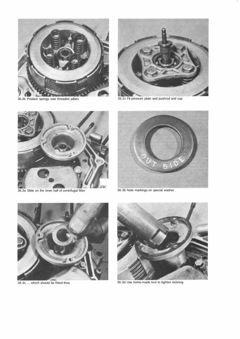
36.2b Position springs over threaded pillars
/P.36.3a Slide on the inner half of centrifugal filter
36.2c Fit pressure plate and pushrod and cup
36.3b Note markings on special washer
I
36.3c ... which should be fitted thus 36.3d Use home-made tool to tighten lockring
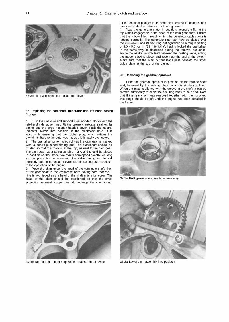
44 Chapter 1 Engine, clutch and gearbox
36.3e Fit new gasket and replace the cover
37 Replacing the camshaft, generator and left-hand casingfittings
1 Turn the unit over and support it on wooden blocks with theleft-hand side uppermost. Fit the gauze crankcase strainer, itsspring and the large hexagon-headed cover. Push the neutralindicator switch into position in the crankcase bore. It isworthwhile ensuring that the rubber plug, which retains theswitch, is fitted to the outer casing, as this is easily overlooked.2 The crankshaft pinion which drives the cam gear is markedwith a centre-punched timing dot. The crankshaft should berotated so that this mark is at the top, nearest to the cam gear.The cam gear has a corresponding mark, and should be placedin position so that these two marks correspond exactly. As longas this precaution is observed, the valve timing will be setcorrectly, but on no account overlook this setting as it is criticalto the operation of the engine.3 Place the shim under the head of the cam gear shaft, thenfit the gear shaft in the crankcase bore, taking care that the 0ring is not nipped as the head of the shaft enters its recess. Thehead of the shaft should be positioned so that the smallprojecting segment is uppermost; do not forget the small spring.
Fit the endfloat plunger in its bore, and depress it against springpressure while the retaining bolt is tightened.4 Place the generator stator in position, noting the flat at thetop which engages with the head of the cam gear shaft. Ensurethat the rubber fillet through which the generator cables pass islocated correctly. The generator rotor can now be placed overthe mainshaft, and its securing nut tightened to a torque settingof 4.0 - 5.0 kgf m (29 - 36 Ibf ft), having locked the crankshaftin the same way as described during the removal sequence.Route the neutral switch lead between the casting webs, notingthe rubber packing piece, and reconnect the end at the switch.Make sure that the main output leads pass beneath the smallguide plate at the top of the casing.
38 Replacing the gearbox sprocket
1 Place the gearbox sprocket in position on the splined shaftend, followed by the locking plate, which is similarly splined.When the plate is aligned with the groove in the shaft, it can berotated sufficiently to allow the securing bolts to be fitted. Notethat if the rear chain was removed together with the sprocket,this stage should be left until the engine has been installed inthe frame.
37.1a Refit gauze crankcase filter assembly
37.1b Do not omit rubber stop which retains neutral switch 37.2a Lower cam assembly into position

37.2b ... aligning the timing marks as shown 37.3a Do not omit thrust washer or small spring whenrefitting cam gear shaft
37.3b Depress end float plunger while single bolt is tightened 37.4a Reconnect lead to neutral switch
37.4b Ensure that generator leads pass behind guide plate 38.1 Fit sprocket and retain with the locking plate and bolts
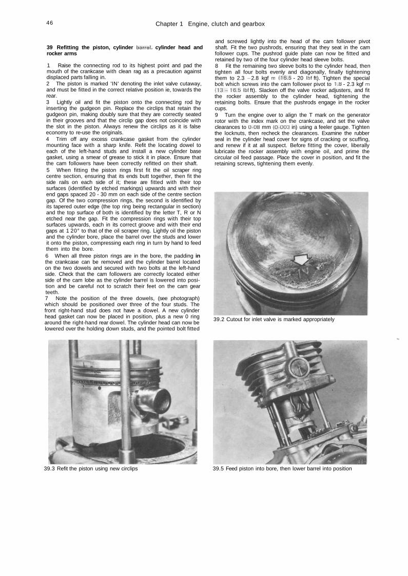
46 Chapter 1 Engine, clutch and gearbox
39 Refitting the piston, cylinder barrel, cylinder head androcker arms
1 Raise the connecting rod to its highest point and pad themouth of the crankcase with clean rag as a precaution againstdisplaced parts falling in.2 The piston is marked 'IN' denoting the inlet valve cutaway,and must be fitted in the correct relative position ie, towards therear.3 Lightly oil and fit the piston onto the connecting rod byinserting the gudgeon pin. Replace the circlips that retain thegudgeon pin, making doubly sure that they are correctly seatedin their grooves and that the circlip gap does not coincide withthe slot in the piston. Always renew the circlips as it is falseeconomy to re-use the originals.4 Trim off any excess crankcase gasket from the cylindermounting face with a sharp knife. Refit the locating dowel toeach of the left-hand studs and install a new cylinder basegasket, using a smear of grease to stick it in place. Ensure thatthe cam followers have been correctly refitted on their shaft.5 When fitting the piston rings first fit the oil scraper ringcentre section, ensuring that its ends butt together, then fit theside rails on each side of it; these are fitted with their topsurfaces (identified by etched markings) upwards and with theirend gaps spaced 20 - 30 mm on each side of the centre sectiongap. Of the two compression rings, the second is identified byits tapered outer edge (the top ring being rectangular in section)and the top surface of both is identified by the letter T, R or Netched near the gap. Fit the compression rings with their topsurfaces upwards, each in its correct groove and with their endgaps at 1 20° to that of the oil scraper ring. Lightly oil the pistonand the cylinder bore, place the barrel over the studs and lowerit onto the piston, compressing each ring in turn by hand to feedthem into the bore.6 When all three piston rings are in the bore, the padding inthe crankcase can be removed and the cylinder barrel locatedon the two dowels and secured with two bolts at the left-handside. Check that the cam followers are correctly located eitherside of the cam lobe as the cylinder barrel is lowered into posi-tion and be careful not to scratch their feet on the cam gearteeth.7 Note the position of the three dowels, (see photograph)which should be positioned over three of the four studs. Thefront right-hand stud does not have a dowel. A new cylinderhead gasket can now be placed in position, plus a new 0 ringaround the right-hand rear dowel. The cylinder head can now belowered over the holding down studs, and the pointed bolt fitted
and screwed lightly into the head of the cam follower pivotshaft. Fit the two pushrods, ensuring that they seat in the camfollower cups. The pushrod guide plate can now be fitted andretained by two of the four cylinder head sleeve bolts.8 Fit the remaining two sleeve bolts to the cylinder head, thentighten all four bolts evenly and diagonally, finally tighteningthem to 2.3 - 2.8 kgf m (16.5 - 20 Ibf ft). Tighten the specialbolt which screws into the cam follower pivot to 1.8 - 2.3 kgf m( 1 3 - 16.5 Ibf ft). Slacken off the valve rocker adjusters, and fitthe rocker assembly to the cylinder head, tightening theretaining bolts. Ensure that the pushrods engage in the rockercups.9 Turn the engine over to align the T mark on the generatorrotor with the index mark on the crankcase, and set the valveclearances to 0-08 mm (0-003 in) using a feeler gauge. Tightenthe locknuts, then recheck the clearances. Examine the rubberseal in the cylinder head cover for signs of cracking or scuffing,and renew if it at all suspect. Before fitting the cover, liberallylubricate the rocker assembly with engine oil, and prime thecircular oil feed passage. Place the cover in position, and fit theretaining screws, tightening them evenly.
39.2 Cutout for inlet valve is marked appropriately
^
39.3 Refit the piston using new circlips 39.5 Feed piston into bore, then lower barrel into position
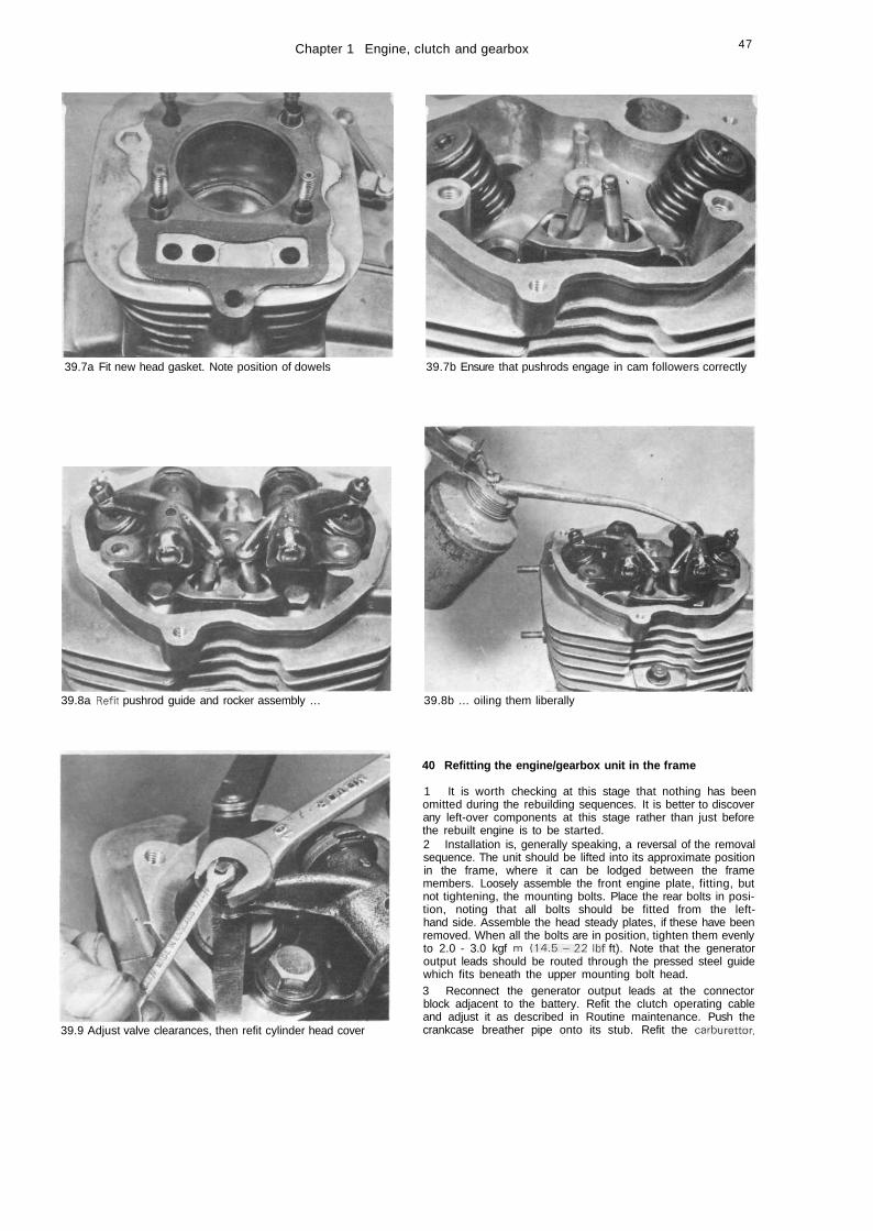
Chapter 1 Engine, clutch and gearbox 47
39.7a Fit new head gasket. Note position of dowels 39.7b Ensure that pushrods engage in cam followers correctly
39.8a Refit pushrod guide and rocker assembly ... 39.8b ... oiling them liberally
39.9 Adjust valve clearances, then refit cylinder head cover
40 Refitting the engine/gearbox unit in the frame
1 It is worth checking at this stage that nothing has beenomitted during the rebuilding sequences. It is better to discoverany left-over components at this stage rather than just beforethe rebuilt engine is to be started.2 Installation is, generally speaking, a reversal of the removalsequence. The unit should be lifted into its approximate positionin the frame, where it can be lodged between the framemembers. Loosely assemble the front engine plate, fitting, butnot tightening, the mounting bolts. Place the rear bolts in posi-tion, noting that all bolts should be fitted from the left-hand side. Assemble the head steady plates, if these have beenremoved. When all the bolts are in position, tighten them evenlyto 2.0 - 3.0 kgf m ( 1 4 . 5 - 2 2 Ibf ft). Note that the generatoroutput leads should be routed through the pressed steel guidewhich fits beneath the upper mounting bolt head.3 Reconnect the generator output leads at the connectorblock adjacent to the battery. Refit the clutch operating cableand adjust it as described in Routine maintenance. Push thecrankcase breather pipe onto its stub. Refit the carburettor.
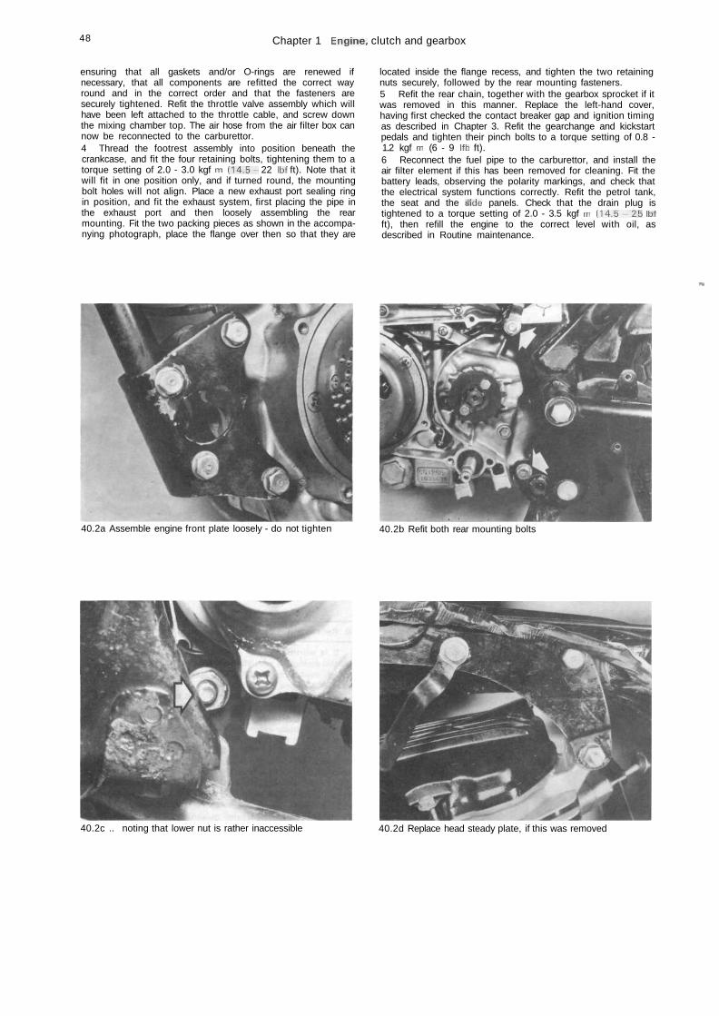
48 Chapter 1 Engine, clutch and gearbox
ensuring that all gaskets and/or O-rings are renewed ifnecessary, that all components are refitted the correct wayround and in the correct order and that the fasteners aresecurely tightened. Refit the throttle valve assembly which willhave been left attached to the throttle cable, and screw downthe mixing chamber top. The air hose from the air filter box cannow be reconnected to the carburettor.4 Thread the footrest assembly into position beneath thecrankcase, and fit the four retaining bolts, tightening them to atorque setting of 2.0 - 3.0 kgf m (14.5- 22 Ibf ft). Note that itwill fit in one position only, and if turned round, the mountingbolt holes will not align. Place a new exhaust port sealing ringin position, and fit the exhaust system, first placing the pipe inthe exhaust port and then loosely assembling the rearmounting. Fit the two packing pieces as shown in the accompa-nying photograph, place the flange over then so that they are
located inside the flange recess, and tighten the two retainingnuts securely, followed by the rear mounting fasteners.5 Refit the rear chain, together with the gearbox sprocket if itwas removed in this manner. Replace the left-hand cover,having first checked the contact breaker gap and ignition timingas described in Chapter 3. Refit the gearchange and kickstartpedals and tighten their pinch bolts to a torque setting of 0.8 -1.2 kgf m (6 - 9 Ifb ft).6 Reconnect the fuel pipe to the carburettor, and install theair filter element if this has been removed for cleaning. Fit thebattery leads, observing the polarity markings, and check thatthe electrical system functions correctly. Refit the petrol tank,the seat and the sfide panels. Check that the drain plug istightened to a torque setting of 2.0 - 3.5 kgf m ( 1 4 . 5 - 2 5 Ibfft), then refill the engine to the correct level with oil, asdescribed in Routine maintenance.
•v
40.2a Assemble engine front plate loosely - do not tighten 40.2b Refit both rear mounting bolts
40.2c .. noting that lower nut is rather inaccessible 40.2d Replace head steady plate, if this was removed
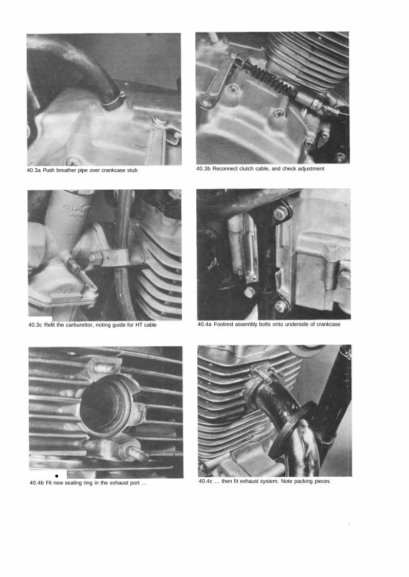
40.3a Push breather pipe over crankcase stub 40.3b Reconnect clutch cable, and check adjustment
40.3c Refit the carburettor, noting guide for HT cable 40.4a Footrest assembly bolts onto underside of crankcase
•40.4b Fit new sealing ring in the exhaust port ... 40.4c ... then fit exhaust system. Note packing pieces
.
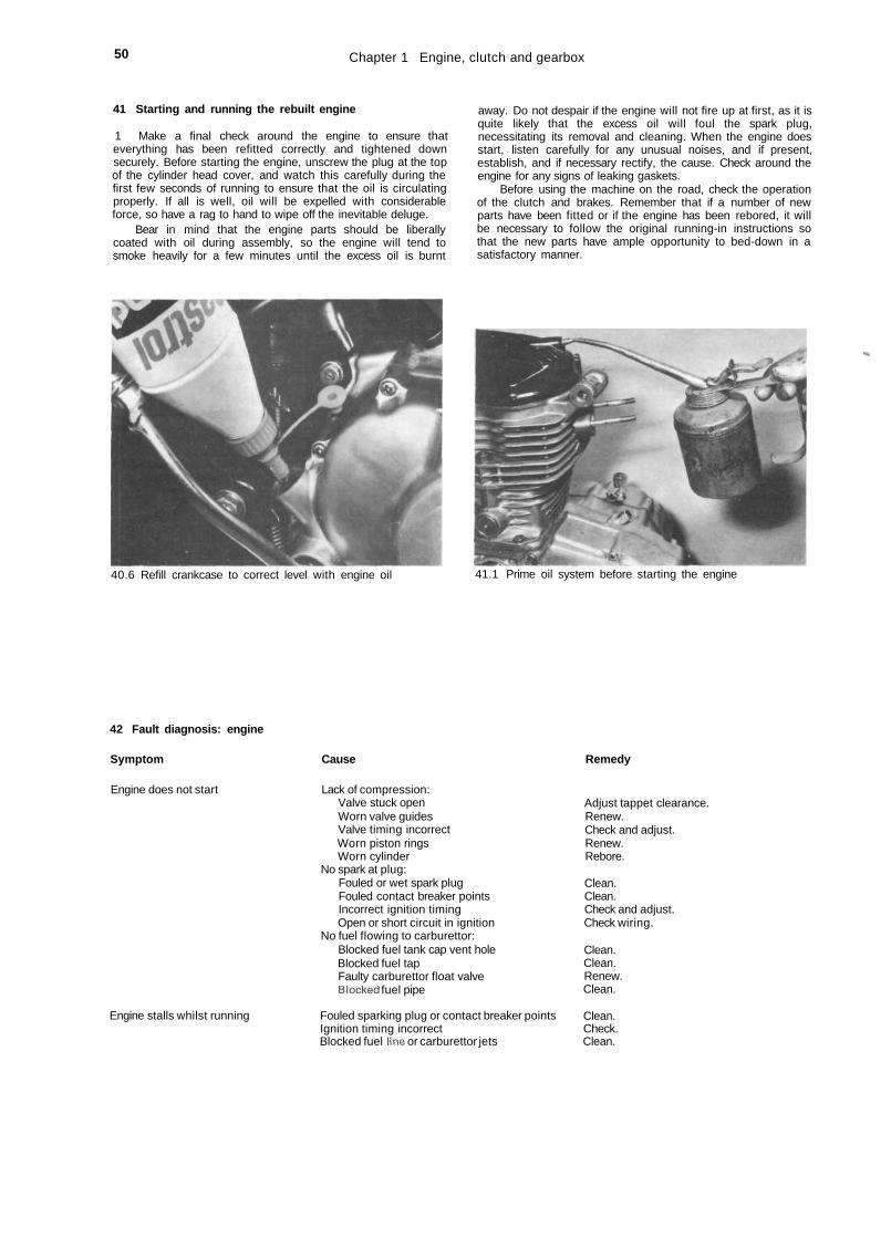
50 Chapter 1 Engine, clutch and gearbox
41 Starting and running the rebuilt engine
1 Make a final check around the engine to ensure thateverything has been refitted correctly and tightened downsecurely. Before starting the engine, unscrew the plug at the topof the cylinder head cover, and watch this carefully during thefirst few seconds of running to ensure that the oil is circulatingproperly. If all is well, oil will be expelled with considerableforce, so have a rag to hand to wipe off the inevitable deluge.
Bear in mind that the engine parts should be liberallycoated with oil during assembly, so the engine will tend tosmoke heavily for a few minutes until the excess oil is burnt
away. Do not despair if the engine will not fire up at first, as it isquite likely that the excess oil will foul the spark plug,necessitating its removal and cleaning. When the engine doesstart, listen carefully for any unusual noises, and if present,establish, and if necessary rectify, the cause. Check around theengine for any signs of leaking gaskets.
Before using the machine on the road, check the operationof the clutch and brakes. Remember that if a number of newparts have been fitted or if the engine has been rebored, it willbe necessary to follow the original running-in instructions sothat the new parts have ample opportunity to bed-down in asatisfactory manner.
-
40.6 Refill crankcase to correct level with engine oil 41.1 Prime oil system before starting the engine
42 Fault diagnosis: engine
Symptom Cause Remedy
Engine does not start
Engine stalls whilst running
Lack of compression:Valve stuck openWorn valve guidesValve timing incorrectWorn piston ringsWorn cylinder
No spark at plug:Fouled or wet spark plugFouled contact breaker pointsIncorrect ignition timingOpen or short circuit in ignition
No fuel flowing to carburettor:Blocked fuel tank cap vent holeBlocked fuel tapFaulty carburettor float valveBlocked fuel pipe
Fouled sparking plug or contact breaker pointsIgnition timing incorrectBlocked fuel line or carburettor jets
Adjust tappet clearance.Renew.Check and adjust.Renew.Rebore.
Clean.Clean.Check and adjust.Check wiring.
Clean.Clean.Renew.Clean.
Clean.Check.Clean.
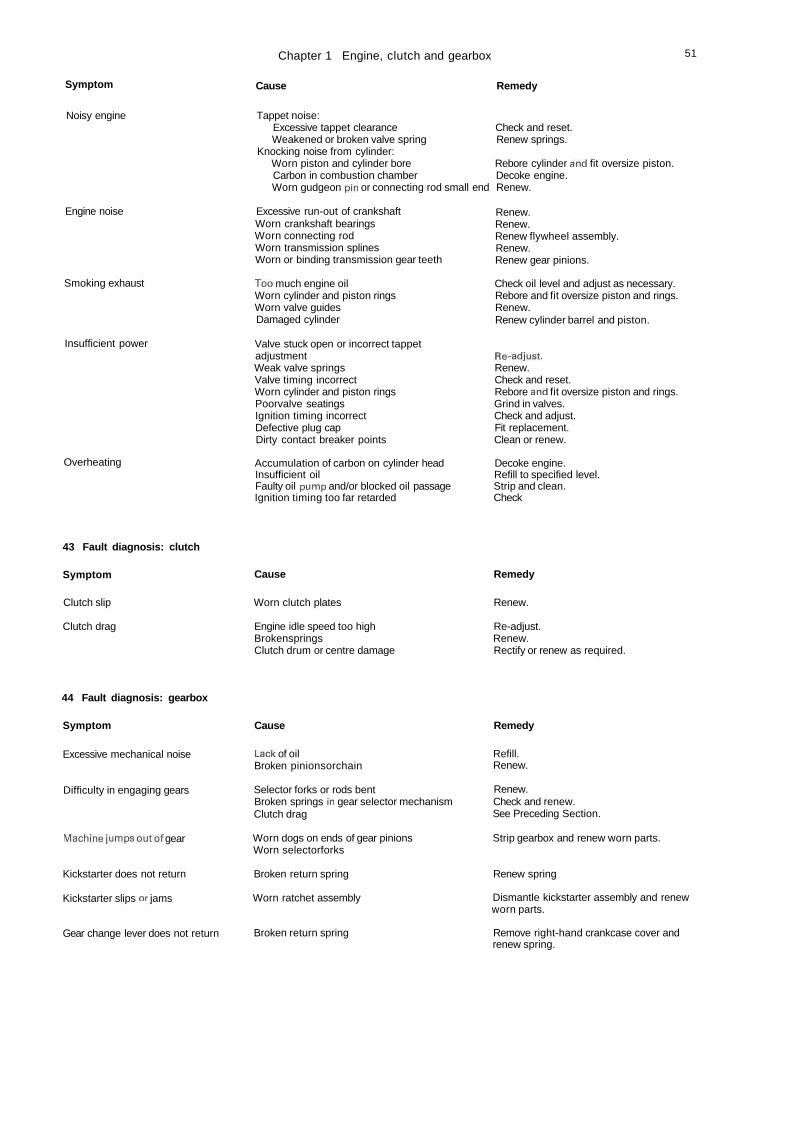
Chapter 1 Engine, clutch and gearbox 51
Symptom Cause Remedy
Noisy engine
Engine noise
Smoking exhaust
Insufficient power
Overheating
Tappet noise:Excessive tappet clearance Check and reset.Weakened or broken valve spring Renew springs.
Knocking noise from cylinder:Worn piston and cylinder bore Rebore cylinder and fit oversize piston.Carbon in combustion chamber Decoke engine.Worn gudgeon pin or connecting rod small end Renew.
Excessive run-out of crankshaftWorn crankshaft bearingsWorn connecting rodWorn transmission splinesWorn or binding transmission gear teeth
Too much engine oilWorn cylinder and piston ringsWorn valve guidesDamaged cylinder
Valve stuck open or incorrect tappetadjustmentWeak valve springsValve timing incorrectWorn cylinder and piston ringsPoorvalve seatingsIgnition timing incorrectDefective plug capDirty contact breaker points
Accumulation of carbon on cylinder headInsufficient oilFaulty oil pump and/or blocked oil passageIgnition timing too far retarded
Renew.Renew.Renew flywheel assembly.Renew.Renew gear pinions.
Check oil level and adjust as necessary.Rebore and fit oversize piston and rings.Renew.Renew cylinder barrel and piston.
Re-adjust.Renew.Check and reset.Rebore and fit oversize piston and rings.Grind in valves.Check and adjust.Fit replacement.Clean or renew.
Decoke engine.Refill to specified level.Strip and clean.Check
43 Fault diagnosis: clutch
Symptom Cause Remedy
Clutch slip
Clutch drag
Worn clutch plates
Engine idle speed too highBrokenspringsClutch drum or centre damage
Renew.
Re-adjust.Renew.Rectify or renew as required.
44 Fault diagnosis: gearbox
Symptom Cause Remedy
Excessive mechanical noise
Difficulty in engaging gears
Machinejumpsoutof gear
Kickstarter does not return
Kickstarter slips or jams
Gear change lever does not return
Lack of oilBroken pinionsorchain
Selector forks or rods bentBroken springs in gear selector mechanismClutch drag
Worn dogs on ends of gear pinionsWorn selectorforks
Broken return spring
Worn ratchet assembly
Broken return spring
Refill.Renew.
Renew.Check and renew.See Preceding Section.
Strip gearbox and renew worn parts.
Renew spring
Dismantle kickstarter assembly and renewworn parts.
Remove right-hand crankcase cover andrenew spring.
Chapter 2 Fuel system and lubricationRefer to Chapter 7 for information relating to the 1985 on Brazilian models
Contents
f
f
General descriptionPetrol tank : removal and replacementPetrol feed pipe : examinationPetrol tap : removal, repair and replacementCarburettor: removal - pre (T)PFC typeCarburettor: overhaul - pre (T)PFC typeCarburettor: adjustment - pre (T)PFC type .Carburettor settings
1 Carburettor: (T)PFC type 92 Air cleaner: removal, cleaning and replacement of the3 elements 104 Exhaust system: general 115 Oil pump: removal, examination and renovation 126 Oil filters: location and cleaning 137 Fault diagnosis 14
Specifications
Fuel tank capacityOverall 10 litres (2.2 Imp gal)Including reserve of 2 litres (0.4 Imp gal)Fuel grade and type Either leaded three-or four-star (minimum octane rating of 91) or
unleaded premium
CarburettorID number - by machine serial (engine) number:
CG125 up to 1020010 077A-ACG125 1020011 to 1104204 PD88E-A/BCG125 1104205 on, CG125 K1, CG125-B up to1422468 PD88E-CCG125-B 1422469 on PD88E-ECG125-C up to 1608462 PD45C-A*CG125-C 1608463 on, CG125-E PD45C-C*•Indicates (T)PFC type carburettor - see Chapter 7 for details
077A-A PD88E-A/B/C/E PD45C-A/CMain jet 92 100 95(-A), 85(-C)Pilot (slow) jet 38 40(-E only)* 38(-A), 40(-C)Needle clip position — grooves from top 3rd 3rd N/AvPilot screw - turns out from fully closed 1^ 1-J N/AvFloat height 24.0 mm (0.95 in) 18.5 mm (0.73 in) N/AvIdle speed 1 1 0 0 - 1300 rpm 1200 rpm 1200 rpm* Pilot jet not removable on PD88E-A/B/C carburettors
Engine/gearbox lubricationCapacity - approx 1.0 litre (1.76 Imp pint)Recommended oil Good quality SAE 10W/40 engine oil, API class SE or SF
1 General description
The fuel system comprises a petrol tank from which petrolis fed by gravity to the float chamber. It is controlled by a petroltap with a built-in filter. The tap has three positions: 'Off', 'On','Reserve', the latter providing a reserve supply of petrol whenthe main supply has run out. For cold starting the carburettorhas a manually operated choke. The machine should run on'Choke' for the least amount of time.
The lubrication system is of the pressure fed type, supplyingoil to almost every part of the engine. There is a centrifugal filtermounted directly on the end of the crankshaft. Centrifugal forcecaused by the rotation of the engine throws the heavierimpurities outwards where they stick to the walls, allowing onlythe clean, lighter oil through. Oil is picked up by the oil pumpand pressure fed through the right-hand crankcase where it isdiverted into two routes. In one direction it goes through apassage in the right-hand crankcase cover and then through theoil filter to the crankshaft. The other direction takes the oilthrough a passage via a cylinder head stud to the rocker arms.The transmission also receives oil under pressure, relying uponthis simple yet very efficient system.
2 Petrol tank: removal and replacement
1 The fuel tank is not bolted to the machine in any way. It isheld in place by three rubbers; two at the inner front and one atthe rear under the seat, which it is necessary to remove.2 Unfasten the bolt on each side of the rear of the seat. Lift upthe back a little and pull back until the seat disengages with itslocation bracket and lifts clear.3 Turn the fuel to 'Off' position and ease off the rubber fuelfeed pipe clip and pipe. Lift the rear of the tank, pull to the rear,then lift away.4 If difficulty is found in replacing the tank, apply a smallamount of lubricant to the tank front rubbers before reassembly.
3 Petrol feed pipe: examination
The petrol feed pipe is made from thin walled syntheticrubber and is of the push-on type. It is only necessary to replacethe pipe if it becomes hard or splits. It is unlikely that the retain-ing clips should need replacing due to fatigue as the main sealbetween the pipe and union is effected by an 'interference' fit.
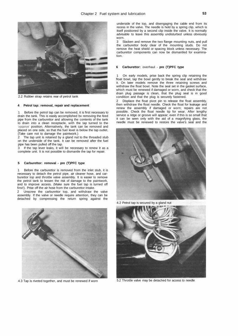
Chapter 2 Fuel system and lubrication 53
2.2 Rubber strap retains rear of petrol tank
4 Petrol tap: removal, repair and replacement
1 Before the petrol tap can be removed, it is first necessary todrain the tank. This is easily accomplished bv removing the feedpipe from the carburettor and allowing the contents of the tankto drain into a clean receptacle, with the tap turned to the'reserve' position. Alternatively, the tank can be removed andplaced on one side, so that the fuel level is below the tap outlet.(Take care not to damage the paintwork.)2 The tap unit is retained by a gland nut to the threaded stubon the underside of the tank. It can be removed after the fuelpipe has been pulled off the tap.3 If the tap lever leaks, it will be necessary to renew it as acomplete unit. It is not possible to dismantle the tap for repair.
5 Carburettor: removal - pre (T)PFC type
1 Before the carburettor is removed from the inlet stub, it isnecessary to detach the petrol pipe, air cleaner hose, and car-burettor top and throttle valve assembly. It is easier to removethe petrol tank to lessen the risk of damage to the paintwork,and to improve access. (Make sure the fuel tap is turned offfirst!). Prise off the air hose from the carburettor intake.2 Unscrew the carburettor top, and withdraw the valveassembly. If the valve or needle require attention, they can bedetached by compressing the return spring against the
underside of the top, and disengaging the cable end from itsrecess in the valve. The needle is held by a spring clip, which isitself positioned by a second clip inside the valve. It is normallyadvisable to leave this assembly undisturbed unless obviouslyworn.3 Slacken and remove the two flange mounting nuts, and pullthe carburettor body clear of the mounting studs. Do notremove the heat shield or spacing block unless necessary. Thecarburettor components can now be dismantled for examina-tion.
6 Carburettor: overhaul - pre (T)PFC type
1 On early models, prise back the spring clip retaining thefloat bowl, tap the bowl gently to break the seal and withdrawit. On later models remove the three retaining screws andwithdraw the float bowl. Note the seal set in the gasket surface,which must be renewed if damaged or worn, and check that thedrain plug passage is clean, that the plug seal is in goodcondition and that the plug is securely fastened.2 Displace the float pivot pin to release the float assembly,then withdraw the float needle. Check the float for leakage andrenew the assembly if damaged or worn; repairs are notpossible. Check the float needle tip for wear. After lengthyservice a ridge or groove will appear; even if this is so small thatit can be seen only with the aid of a magnifying glass, theneedle must be renewed to restore the valve's seal and the
4.2 Petrol tap is secured by a gland nut
4.3 Tap is riveted together, and must be renewed if worn 5.2 Throttle valve may be detached for access to needle

54 Chapter 2 Fuel system and lubrication
5.3a Remove carburettor body from inlet port 5.3b It is not normally necessary to remove heat shield
carburettor fuel level. If the needle seat is worn or damaged itmust be renewed also; on later models note that this meansrenewing the complete carburettor assembly.3 The main jet is screwed into the jet holder which is itselfscrewed into the central column projecting from the carburettorunderside. On certain models (see Specifications) the pilot jetcan be unscrewed from its location next to the central column;on all others it is fixed and can only be cleaned in place, usingcompressed air. When removing jets use only a close-fittingscrewdriver or spanner to minimise the risk of damage, and donot exert excessive force. Before removing the needle jet, notecarefully exactly how it is positioned above the jet holder, beforepressing it out using a slim wooden rod.4 The throttle stop screw is located in the right-hand side ofthe carburettor body, at the base of the throttle valve bore; thepilot screw is located either adjacent to the throttle stop screw(early models) or projecting downwards from the carburettorbody, at the front of the float bowl. To remove these, first screweach in until it seats lightly and note the exact number of turnsrequired to do this, then unscrew it and note the presence of thesmall spring under each. On refitting, screw it in until it seatslightly then unscrew it by the previously noted number of turnsto restore it to its original position.5 Check the throttle valve components for wear or damageand renew any defective item. If the valve is slack in thecarburettor body, then either the valve or the completecarburettor assembly must be renewed. Similarly, check thechoke mechanism for wear or damage, noting that the completecarburettor assembly must be renewed to rectify any problems.On early models check particularly that the spring-loaded flap isin one piece and free from cracks; on later models check thatthe butterfly retaining screws are securely fastened.6 Before the carburettor is reassembled, using the reverse ofthe dismantling procedure, it should be cleaned out thoroughlyusing compressed air. Avoid using a piece of rag since there isalways risk of particles of lint obstructing the internal passage-ways or the jet orifices.7 Never use a piece of wire or any poinced metal object toclear a blocked jet. It is only too easy to enlarge the jet underthese circumstances, and increase the rate of petrol consump-tion. If compressed air is not available, a blast of air from a tyrepump will usually suffice. As a last resort, a fine nylon bristlemay be used.8 Do not use excessive force when reassembling a car-burettor because it is easy to shear a jet or some of the smallerscrews. Furthermore, the carburettor is cast in a zinc-basedalloy which itself does not have a high tensile strength. If any ofthe castings are damaged during reassembly, they will almostcertainly have to be renewed.
7 Carburettor adjustment - pre (T)PFC type
1 Commence operations by checking the float height, whichwill involve detaching the carburettor, if not already removed,inverting it and removing the float bowl. If the float height iscorrect, the bottom of each float should be the specifieddistance away from the carburettor body mating surface whenthe valve has just closed. To adjust the setting bend the floatarm.2 Replace the carburettor, check that free play is present inthe throttle cable, and with the engine at normal operatingtemperature turn the pilot screw inwards until the enginemisfires or decreases in speed. Note the position of the screw,then turn it outwards until similar symptoms are observed. Thescrew should then be set exactly between these two positions,which should approximate the specified setting.3 When the mixture setting is correct, use the throttle stopscrew to set the idle speed. If a suitable tachometer is notavailable the correct speed can be approximated by finding thelowest speed at which the engine will tick over smoothly andreliably. Adjust the throttle cable, using the adjuster at eitherend of the cable, to give 2 - 6 mm (0.08 - 0.24 in) free playmeasured at the twistgrip flange, ie 10 — 15° of twistgriprotation. Ensure the idle speed remains steady at all handlebarpositions.4 Note that these adjustments should always be made withthe engine at normal operating temperature and with the aircleaner connected, otherwise a false setting will be obtained.
8 Carburettor settings
1 Some of the carburettor settings, such as the sizes of theneedle jet, main jet, and needle position etc are pre-determined by the manufacturer. Under normal circumstances,it is unlikely that these settings will require modification, eventhough there is provision made. If a change appears necessary,it can often be attributed to a developing engine fault.2 As an approximate guide the pilot jet setting controlsengine speed up to j throttle. The throttle slide cutaway con-trols engine speed from ^ to f throttle. The size of the main jetis responsible for engine speed at the final f to full throttle. Itshould be added however that these are only guide lines. Thereis no clearly defined demarcation line due to a certain amount ofoverlap that occurs between the carburettor componentsinvolved.
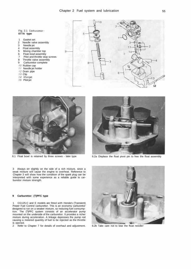
Chapter 2 Fuel system and lubrication 55
Fig. 2.1 Carburettor -077A type
1 Gasket set2 Needle valve assembly3 Needle jet4 Float assembly5 Mixing chamber top6 Float bowl assembly7 Pilot and throttle stop screws8 Throttle valve assembly9 Carburettor complete10 Rubber cap11 Needle jet holder12 Drain pipe13 Clip14 Main jet15 Pilot jet
12
6.1 Float bowl is retained by three screws - later type 6.2a Displace the float pivot pin to free the float assembly
3 Always err slightly on the side of a rich mixture, since aweak mixture will cause the engine to overheat. Reference toChapter 3 will show how the condition of the spark plug can beinterpreted with some experience as a reliable guide to car-burettor mixture strength.
9 Carburettor: (T)PFC type
1 CG125-C and E models are fitted with Honda's (Transient)Power Fuel Control carburettor. This is an economy carburettordesigned to run on a weaker mixture, so reducing fuel consump-tion. The (T)PFC system consists of an accelerator pumpmounted on the underside of the carburettor. It provides a richermixture during acceleration. A linkage depresses the pump rodcausing a metered quantity of fuel to be injected as the throttleis opened.2 Refer to Chapter 7 for details of overhaul and adjustment. 6.2b Take care not to lose the float needle!
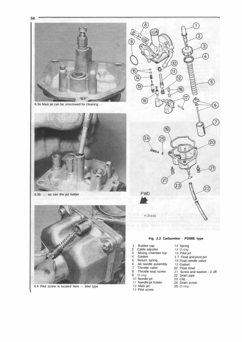
6.3a Main jet can be unscrewed for cleaning .
6.3b . . . as can the jet holder
Fig. 2.2 Carburettor - PD88E type
6.4 Pilot screw is located here — later type
1 Rubber cap2 Cable adjuster3 Mixing chamber top
Gasket5 Return spring6 Jet needle assembly7 Throttle valve8 Throttle stop screw9 O-ring10 Needle jet11 Needle jet holder12 Main jet13 Pilot screw
14 Spring15 O-ring16 Pilot jet1 7 Float and pivot pin18 Float needle valve19 Gasket20 Float bowl21 Screw and washer - 3 off22 Drain pipe23 Clip24 Drain screw25 O-ring
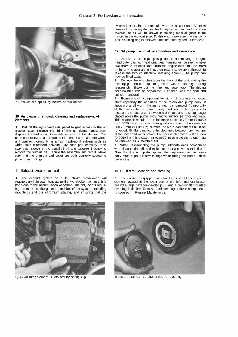
Chapter 2 Fuel system and lubrication 57
7.2 Adjust idle speed by means of this screw
10 Air cleaner: removal, cleaning and replacement ofelements
1 Pull off the right-hand side panel to gain access to the aircleaner case. Release the lid of the air cleaner case, thendisplace the leaf spring to enable removal of the element. Thefoam filter sleeves can be slid off the central core, and the wholeunit washer thoroughly in a high flash-point solvent such aswhite spirit (Stoddard solvent). Dry each part carefully, thensoak each sleeve in the specified oil and squeeze it gently toremove the surplus oil. Rebuild the assembly and refit it. Makesure that the element and cover are both correctly seated toprevent air leakage.
system is kept airtight, particularly at the exhaust port. Air leakshere will cause mysterious backfiring when the machine is onoverrun, as air will be drawn in causing residual gases to beignited in the exhaust pipe. To this end, make sure that the com-posite sealing ring is renewed each time the system is removed.
12 Oil pump: removal, examination and renovation
1 Access to the oil pump is gained after removing the right-hand outer casing. The driving gear housing will be seen to havetwo holes in its outer face. Turn the engine over until the holesin the driving gear are in line, then pass a screwdriver through torelease the two countersunk retaining screws. The pump cannow be lifted away.2 Remove the end plate from the back of the unit, noting thelocating pip and corresponding recess which must align duringreassembly. Shake out the inner and outer rotor. The drivinggear housing can be separated, if desired, and the gear andspindle removed.3 Examine each component for signs of scuffing and wear.Note especially the condition of the rotors and pump body. Ifthese are at all worn, the pump must be renewed. Temporarilyfit the rotors to the pump body and use feeler gauges tomeasure the clearance between the rotors and a straightedgeplaced acoss the pump body mating surface (ie rotor endfloat).This clearance should be in the range 0.15 - 0.20 mm (0.0059— 0.0079 in) if the pump is in good condition; if the clearanceis 0.25 mm (0.0098 in) or more the worn components must berenewed. Similarly measure the clearance between any two tipsof the inner and outer rotors. The correct clearance is 0.1 5 mm(0.0059 in); if it is 0.20 mm (0.0079 in) or more the rotors mustbe renewed as a matched set.4 When reassembling the pump, lubricate each componentwith clean engine oil, and make sure that a new gasket is fitted.Note that the end plate pip and the depression in the pumpbody must align. Fit new 0 rings when fitting the pump unit tothe engine.
11 Exhaust system: general
1 The exhaust system on a four-stroke motor-cycle willrequire very little attention, as, unlike two-stroke machines, it isnot prone to the accumulation of carbon. The only points requir-ing attention are the general condition of the system, includingmountings and the chromium plating, and ensuring that the
13 Oil filters: location and cleaning
1 The engine is equipped with two types of oil filter; a gauzeelement located in the lower part of the left-hand crankcase,behind a large hexagon-headed plug, and a crankshaft mountedcentrifugal oil filter. Removal and cleaning of these componentsis covered in Routine Maintenance.
10.1a Air filter element is retained by spring clip 10.1b . . . and can be dismantled for cleaning
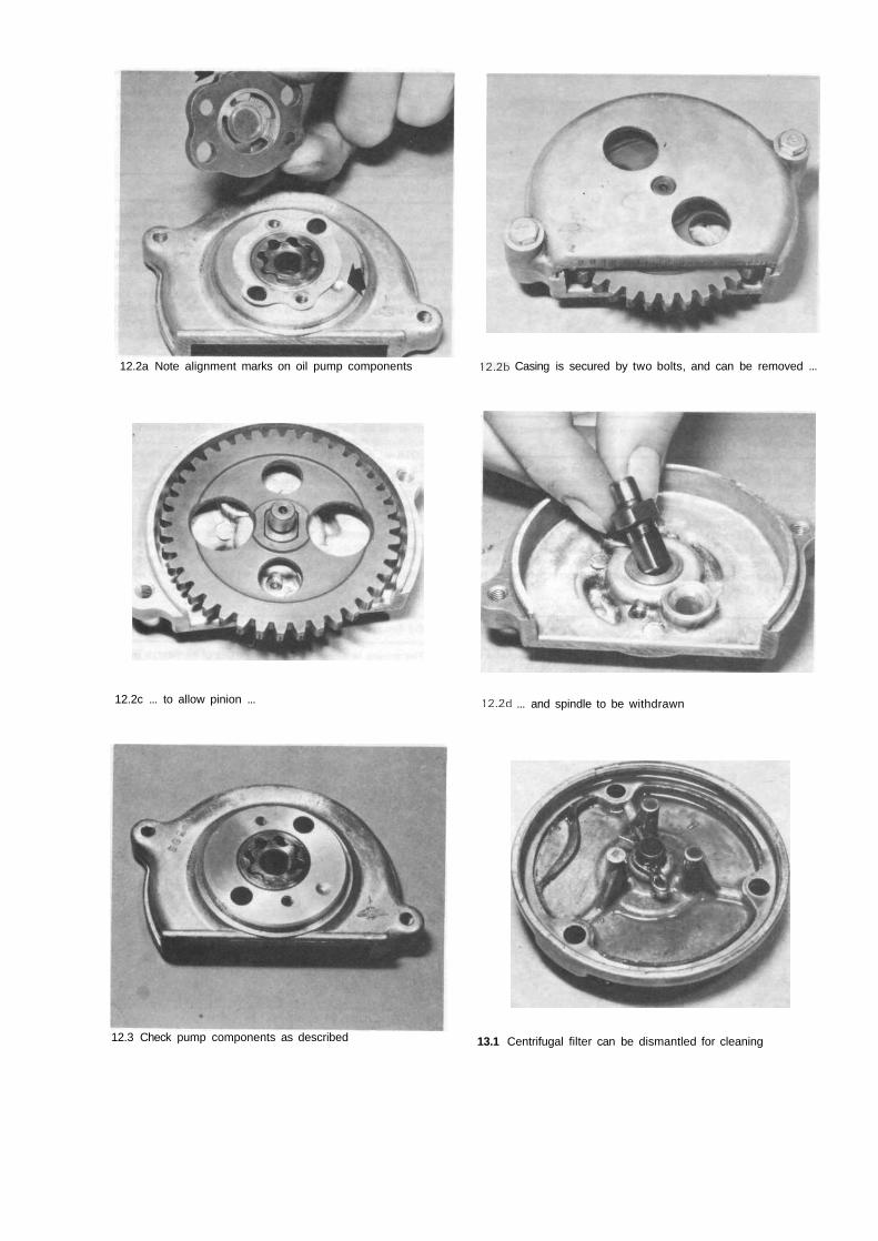
12.2a Note alignment marks on oil pump components 12.2b Casing is secured by two bolts, and can be removed ...
12.2c ... to allow pinion ... 12.2d ... and spindle to be withdrawn
12.3 Check pump components as described 13.1 Centrifugal filter can be dismantled for cleaning
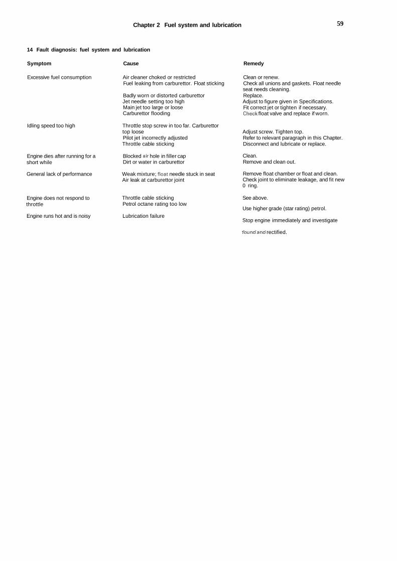
Chapter 2 Fuel system and lubrication 59
14 Fault diagnosis: fuel system and lubrication
Symptom Cause Remedy
Excessive fuel consumption
Idling speed too high
Engine dies after running for ashort while
Air cleaner choked or restrictedFuel leaking from carburettor. Float sticking
Badly worn or distorted carburettorJet needle setting too highMain jet too large or looseCarburettor flooding
Throttle stop screw in too far. Carburettortop loosePilot jet incorrectly adjustedThrottle cable sticking
Blocked air hole in filler capDirt or water in carburettor
Clean or renew.Check all unions and gaskets. Float needleseat needs cleaning.Replace.Adjust to figure given in Specifications.Fit correct jet or tighten if necessary.Check float valve and replace if worn.
Adjust screw. Tighten top.Refer to relevant paragraph in this Chapter.Disconnect and lubricate or replace.
Clean.Remove and clean out.
General lack of performance
Engine does not respond tothrottle
Engine runs hot and is noisy
Weak mixture; float needle stuck in seatAir leak at carburettor joint
Throttle cable stickingPetrol octane rating too low
Lubrication failure
Remove float chamber or float and clean.Check joint to eliminate leakage, and fit new0 ring.
See above.
Use higher grade (star rating) petrol.
Stop engine immediately and investigate
founrfancf rectified.
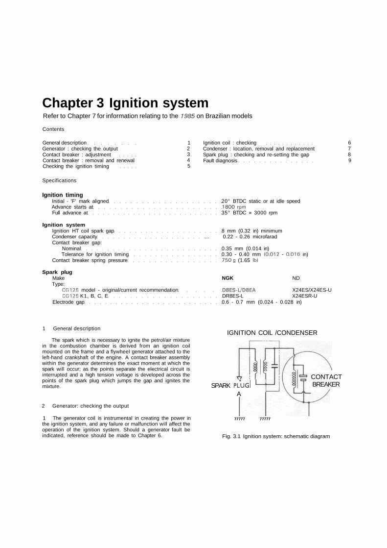
Chapter 3 Ignition systemRefer to Chapter 7 for information relating to the 1985 on Brazilian models
Contents
General descriptionGenerator : checking the outputContact breaker : adjustmentContact breaker : removal and renewalChecking the ignition timing
12345
Ignition coil : checkingCondenser : location, removal and replacementSpark plug : checking and re-setting the gapFault diagnosis
6789
Specifications
Ignition timingInitial - 'F' mark aligned 20° BTDC static or at idle speedAdvance starts at 1800 rpmFull advance at 35° BTDC e 3000 rpm
Ignition systemIgnition HT coil spark gap 8 mm (0.32 in) minimumCondenser capacity ... 0.22 - 0.26 microfaradContact breaker gap:
Nominal 0.35 mm (0.014 in)Tolerance for ignition timing 0.30 - 0.40 mm (0.012 - 0.016 in)
Contact breaker spring pressure 750 g (1.65 1b)
Spark plugMake NGK NDType:
CG125 model - original/current recommendation D8ES-L7D8EA X24ES/X24ES-UCG125 K1, B, C, E DR8ES-L X24ESR-U
Electrode gap 0.6 - 0.7 mm (0.024 - 0.028 in)
1 General description
The spark which is necessary to ignite the petrol/air mixturein the combustion chamber is derived from an ignition coilmounted on the frame and a flywheel generator attached to theleft-hand crankshaft of the engine. A contact breaker assemblywithin the generator determines the exact moment at which thespark will occur; as the points separate the electrical circuit isinterrupted and a high tension voltage is developed across thepoints of the spark plug which jumps the gap and ignites themixture.
2 Generator: checking the output
1 The generator coil is instrumental in creating the power inthe ignition system, and any failure or malfunction will affect theoperation of the ignition system. Should a generator fault beindicated, reference should be made to Chapter 6.
IGNITION COIL /CONDENSER
SPARK PLUGl '—'A
CONTACTBREAKER
77777 77777
Fig. 3.1 Ignition system: schematic diagram
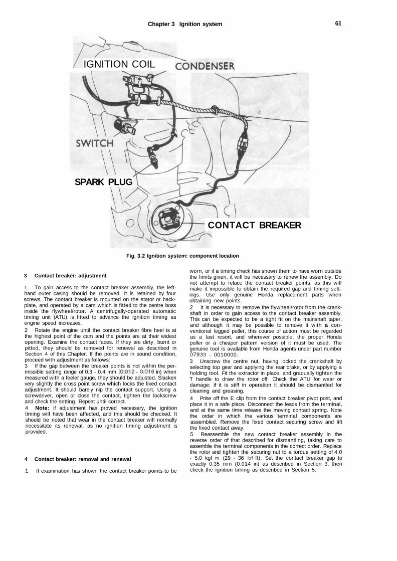
Chapter 3 Ignition system 61
IGNITION COIL CONDENSER
SPARK PLUG
CONTACT BREAKER
Fig. 3.2 Ignition system: component location
3 Contact breaker: adjustment
1 To gain access to the contact breaker assembly, the left-hand outer casing should be removed. It is retained by fourscrews. The contact breaker is mounted on the stator or back-plate, and operated by a cam which is fitted to the centre bossinside the flywheel/rotor. A centrifugally-operated automatictiming unit (ATU) is fitted to advance the ignition timing asengine speed increases.2 Rotate the engine until the contact breaker fibre heel is atthe highest point of the cam and the points are at their widestopening. Examine the contact faces. If they are dirty, burnt orpitted, they should be removed for renewal as described inSection 4 of this Chapter. If the points are in sound condition,proceed with adjustment as follows:3 If the gap between the breaker points is not within the per-missible setting range of 0.3 - 0.4 mm (0.012 - 0.016 in) whenmeasured with a feeler gauge, they should be adjusted. Slackenvery slightly the cross point screw which locks the fixed contactadjustment. It should barely nip the contact support. Using ascrewdriver, open or close the contact, tighten the lockscrewand check the setting. Repeat until correct.4 Note: if adjustment has proved necessary, the ignitiontiming will have been affected, and this should be checked. Itshould be noted that wear in the contact breaker will normallynecessitate its renewal, as no ignition timing adjustment isprovided.
4 Contact breaker: removal and renewal
1 If examination has shown the contact breaker points to be
worn, or if a timing check has shown them to have worn outsidethe limits given, it will be necessary to renew the assembly. Donot attempt to reface the contact breaker points, as this willmake it impossible to obtain the required gap and timing sett-ings. Use only genuine Honda replacement parts whenobtaining new points.2 It is necessary to remove the flywheel/rotor from the crank-shaft in order to gain access to the contact breaker assembly.This can be expected to be a tight fit on the mainshaft taper,and although it may be possible to remove it with a con-ventional legged puller, this course of action must be regardedas a last resort, and wherever possible, the proper Hondapuller or a cheaper pattern version of it must be used. Thegenuine tool is available from Honda agents under part number07933 - 0010000.3 Unscrew the centre nut, having locked the crankshaft byselecting top gear and applying the rear brake, or by applying aholding tool. Fit the extractor in place, and gradually tighten theT handle to draw the rotor off. Check the ATU for wear ordamage; if it is stiff in operation it should be dismantled forcleaning and greasing.4 Prise off the E clip from the contact breaker pivot post, andplace it in a safe place. Disconnect the leads from the terminal,and at the same time release the moving contact spring. Notethe order in which the various terminal components areassembled. Remove the fixed contact securing screw and liftthe fixed contact away.5 Reassemble the new contact breaker assembly in thereverse order of that described for dismantling, taking care toassemble the terminal components in the correct order. Replacethe rotor and tighten the securing nut to a torque setting of 4.0- 5.0 kgf m (29 - 36 Ibf ft). Set the contact breaker gap toexactly 0.35 mm (0.014 in) as described in Section 3, thencheck the ignition timing as described in Section 5.

62 Chapter 3 Ignition system
3.1 Automatic timing unit in flywheel rotor may be lubricatedlightly
3.3 Check contact breaker gap using feeler gauge
i
4.3 Flywheel rotor centre has thread to accept extractor 4.4 A : E clip. B : Fixed contact securing screw C : Terminal
5 Checking the ignition timing
1 The ignition timing can be checked using a battery and bulbarrangement connected as shown in the accompanyingdiagram. Owners of multimeter test instruments may prefer touse these, set to the most sensitive resistance scale, ascontinuity testers. Note that the easiest way to connect theprobe to the contact breaker assembly is to disconnect thegenerator output lead connector and locate the black orblack/white lead to the points.2 Set the rotor so that the F mark registers with its datummark, then adjust the fixed contact so that the points just startto separate. This will be indicated by the test lamp flickering (orthe meter needle deflecting). Check that the contact breakergap is within the tolerance given.
6 Ignition coil: checking
1 The ignition coil is a sealed unit and designed to give longservice without need for attention., The coil is located under thepetrol tank, which must be removed to gain access.2 A number of tests can be performed using a basic test lamp
6.1 Coil and condenser are located beneath the fuel tank
/

Chapter 3 Ignition system 63
and battery arrangement connected as shown in theaccompanying diagrams. Should any of these checks notproduce the expected result, the coil should be removed andtaken to a Honda Service Agent or Auto-Electrical specialist fora more thorough check.
7 Condenser: location, removal and replacement
1 A condenser is included in the contact breaker circuitry toprevent arcing across the contact breaker points as theyseparate. The condenser is connected in parallel with the pointsand if a fault develops, ignition failure is liable to occur.2 If the engine proves difficult to start, or misfiring occurs, it ispossible that the condenser is at fault. To check, watch thepoints via the rotor apertures when the engine is running. If aspark occurs across the points and they have a blackened andburnt appearance, the condenser can be regarded as un-serviceable.3 It is not possible to fully check the condenser without theappropriate equipment. In view of the low cost involved, it ispreferable to fit a new replacement and observe the effect onengine performance although an approximate test can becarried out as shown in the accompanying diagram.4 The condenser is mounted on the ignition coil assembly bymeans of a metal clamp. Since this fitting provides the earthconnection of the condenser, it follows that the clip shouldmake good contact and be tightened fully.
8 Spark plug: checking and re-setting the gap
1 The spark plug specified as original equipment will provesatisfactory in most operating conditions; alternatives are avail-able to allow for varying altitudes, climatic conditions and theuse to which the machine is put. It a spark plug is suspected ofbeing faulty it can be tested only by the substitution of a brandnew (not second-hand) plug of the correct make, type, and heatrange; always carry a spare on the machine.2 Note that the advice of a competent Honda Service Agentor similar expert should be sought before the plug heat range is
altered from standard. The use of too cold, or hard, a grade ofplug will result in fouling and the use of too hot, or soft, a gradeof plug will result in engine damage due to excess heat beinggenerated. If the correct grade of plug is fitted, however, it willbe possible to use the condition of the spark plug electrodes todiagnose a fault in the engine or to decide whether the engineis operating efficiently or not.
3 Also, always ensure that the plug is of the resistor type(indicated by the letter 'R'), where applicable, so that itsresistance value is correct for the ignition system. The sameapplies to the suppressor cap; if a cap or plug of the wrong typeis fitted, thus producing a much greater or lesser resistancevalue than that for which the ignition system was designed, oneor more components of the system may break down.4 The electrode gap can be assessed using feeler gauges. Ifnecessary, alter the gap by bending the outer electrode,preferably using a proper electrode tool. Never bend the centreelectrode, otherwise the ceramic insulator will crack, and maycause damage to the engine if particles break away whilst theengine is running. If the outer electrode is seriously eroded asshown in the photographs, or if the spark plug is heavily fouled,it should be renewed. Clean the electrodes using a wire brushor a sharp-pointed knife, followed by rubbing a strip of fineemery across the electrodes. If a sand-blaster is used, checkcarefully that there are no particles of sand trapped inside theplug body to fall into the engine at a later date. For this reasonsuch cleaning methods are no longer recommended; if the plugis so heavily fouled it should be renewed.5 Before replacing a spark plug into the cylinder head coatthe threads sparingly with a graphited grease to aid futureremoval. Use the correct sized spanner when tightening theplug otherwise the spanner may slip and damage the ceramicinsulator. The plug should be tightened sufficiently to seat firmlyon the sealing washer, and no more.6 Never overtighten a spark plug otherwise there is risk ofstripping the threads from the cylinder head, especially as it iscast in light alloy. A stripped thread can be repaired withouthaving to scrap the cylinder head by using a 'Helicoil' threadinsert. This is a low-cost service, operated by a number ofdealers.
- o - " +Fig. 3.3 Ignition timing test using battery and bulb arrangement or multimeter
A: Connect to earthB: Connect to moving
contact
C: BatteryD: BulbE: Multimeter
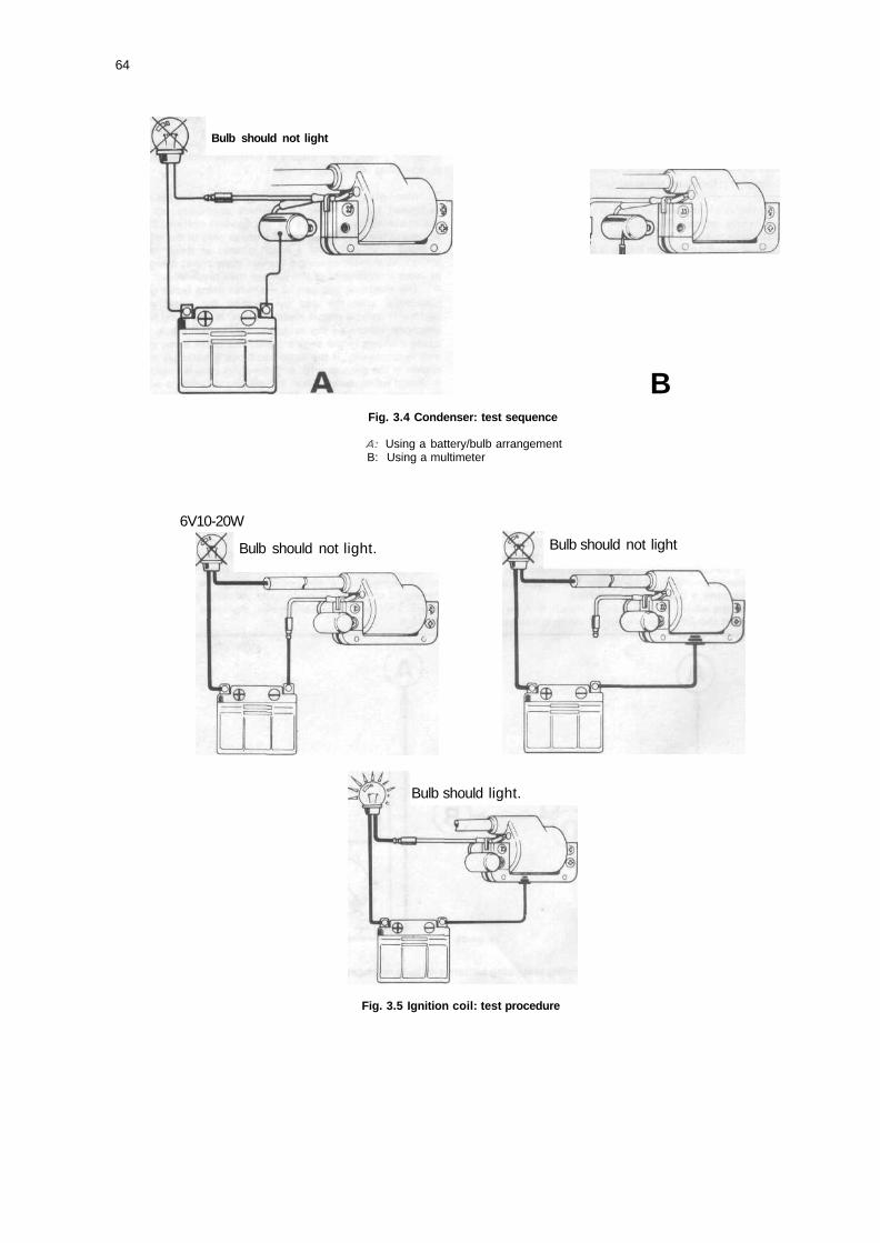
64
Bulb should not light
BFig. 3.4 Condenser: test sequence
A: Using a battery/bulb arrangementB: Using a multimeter
6V10-20W
Bulb should not light. Bulb should not light
Bulb should light.
Fig. 3.5 Ignition coil: test procedure
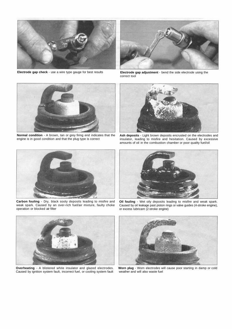
Electrode gap check - use a wire type gauge for best results Electrode gap adjustment - bend the side electrode using thecorrect tool
Normal condition - A brown, tan or grey firing end indicates that theengine is in good condition and that the plug type is correct
Ash deposits - Light brown deposits encrusted on the electrodes andinsulator, leading to misfire and hesitation. Caused by excessiveamounts of oil in the combustion chamber or poor quality fuel/oil
Carbon fouling - Dry, black sooty deposits leading to misfire andweak spark. Caused by an over-rich fuel/air mixture, faulty chokeoperation or blocked air filter
Oil fouling - Wet oily deposits leading to misfire and weak spark.Caused by oil leakage past piston rings or valve guides (4-stroke engine),or excess lubricant (2-stroke engine)
Overheating - A blistered white insulator and glazed electrodes. Worn plug - Worn electrodes will cause poor starting in damp or coldCaused by ignition system fault, incorrect fuel, or cooling system fault weather and will also waste fuel

DO
9 Fault diagnosis
Symptom
: ignition system
Cause
Chapter 3 Ignition system
Remedy
Engine will not start
Engine starts but runs erratically
Plug faultyDefective ignition coilDirty pointsPoor points contact
Plug gap incorrect or has whiskeredIncorrect ignition timingWeak points arm return springDefective ignition coilLow output from flywheel generatorPlug lead insulation breaking down
Check plug and adjust gap or renew.Renew.Clean or renew and check gap.Check for arcing. Renew condenser.
Adjust and clean or renew.Gheck timing and points gap.Renew.Renew after expert testing.Have tested and renew.Check and renew.
Chapter 4 Frame and forksRefer to Chapter 7 for information relating to the 1985 on Brazilian models
Contents
General description 1Front forks : removal - general 2Front forks : removing the fork assembly from the frame 3Front forks : removing the fork legs from the yokes ... 4Steering head bearings : examination and renovation 5Fork yokes : examination 6Fork legs : dismantling, examination and renovation -CG125 model 7Fork legs : dismantling, examination and renovation —CG125 K1, B, C and E models 8Refitting the forks in the frame 9Frame assembly : examination and renovation 10
Swinging arm : examination and renovation 11Rear suspension units : removal, examination andrenovation 12Centre stand : examination 13Footrests: examination 14Rear brake pedal: examination and renovation 15Speedometer head: removal and replacement 16Speedometer cable: examination and renovation 17Dualseat: removal 18Steering lock: removal and replacement 19Cleaning the machine: general 20Fault diagnosis 21
Specifications
Front forksTravel 108 mm (4.25 in)
Standard Wear limitLower leg bore diameter 31.000 - 31.039 mm 31.100 mm (1.2244 in)
(1 .2205- 1.2220 in)Bottom bush/damper piston diameter 30.936 - 30.975 mm 30.900 mm (1.21 65 in)
(1.2180- 1.2195 in)Fork spring free length
CG125 185.90 mm (7.3189 in) 170.00 mm (6.6929 in)CG125 K1, B, C, E 41 1.60 mm (1 6.2047 in) 391.00 mm (1 5.3937 in)
Fork oil capacity - per legCG125 - at oil change 120 - 130 cc (4.22 - 4.58 Imp fl oz)CG125 - at rebuild, CG125 K1, B, C, E 130 - 140 cc (4.58 - 4.93 Imp fl oz)
Recommended fork oil Automatic transmission fluid (ATF) or equivalent fork oil
Rear suspensionTravel 70 mm (2.76 in)
Standard Wear limitSuspension unit spring free length 1 79.80 mm (7.0787 in) 171.00 mm (6.7323 in)Swinging arm pivot bolt to bush clearance 0.10 - 0.30 mm 0.50 mm (0.0197 in)
(0.0039 - 0.0118 in)
1 General description
The Honda CG 125 utilises a frame of open diamond type,being a composite structure of tubular construction with amonocoque spine. The engine unit is bolted between the spine
and the downtube to form a structural part of the frame. Thefront forks are of traditional telescopic design, being controlledby hydraulic dampers. Rear suspension is provided by a swing-ing arm fork, pivoting on replaceable bushes, and controlled byadjustable, hydraulically damped, suspension units.
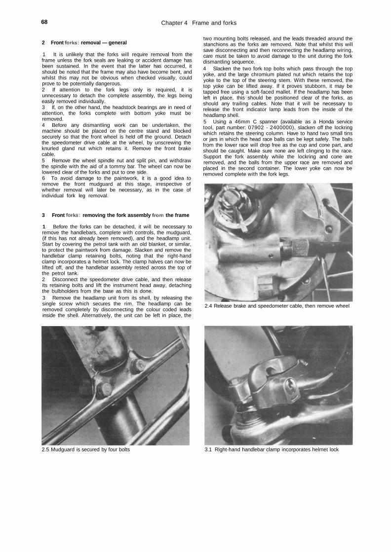
68 Chapter 4 Frame and forks
2 Front forks: removal — general
1 It is unlikely that the forks will require removal from theframe unless the fork seals are leaking or accident damage hasbeen sustained. In the event that the latter has occurred, itshould be noted that the frame may also have become bent, andwhilst this may not be obvious when checked visually, couldprove to be potentially dangerous.2 If attention to the fork legs only is required, it isunnecessary to detach the complete assembly, the legs beingeasily removed individually.3 If, on the other hand, the headstock bearings are in need ofattention, the forks complete with bottom yoke must beremoved.4 Before any dismantling work can be undertaken, themachine should be placed on the centre stand and blockedsecurely so that the front wheel is held off the ground. Detachthe speedometer drive cable at the wheel, by unscrewing theknurled gland nut which retains it. Remove the front brakecable.5 Remove the wheel spindle nut and split pin, and withdrawthe spindle with the aid of a tommy bar. The wheel can now belowered clear of the forks and put to one side.6 To avoid damage to the paintwork, it is a good idea toremove the front mudguard at this stage, irrespective ofwhether removal will later be necessary, as in the case ofindividual fork leg removal.
3 Front forks: removing the fork assembly from the frame
1 Before the forks can be detached, it will be necessary toremove the handlebars, complete with controls, the mudguard,(if this has not already been removed), and the headlamp unit.Start by covering the petrol tank with an old blanket, or similar,to protect the paintwork from damage. Slacken and remove thehandlebar clamp retaining bolts, noting that the right-handclamp incorporates a helmet lock. The clamp halves can now belifted off, and the handlebar assembly rested across the top ofthe petrol tank.2 Disconnect the speedometer drive cable, and then releaseits retaining bolts and lift the instrument head away, detachingthe bulbholders from the base as this is done.3 Remove the headlamp unit from its shell, by releasing thesingle screw which secures the rim. The headlamp can beremoved completely by disconnecting the colour coded leadsinside the shell. Alternatively, the unit can be left in place, the
two mounting bolts released, and the leads threaded around thestanchions as the forks are removed. Note that whilst this willsave disconnecting and then reconnecting the headlamp wiring,care must be taken to avoid damage to the unit during the forkdismantling sequence.4 Slacken the two fork top bolts which pass through the topyoke, and the large chromium plated nut which retains the topyoke to the top of the steering stem. With these removed, thetop yoke can be lifted away. If it proves stubborn, it may betapped free using a soft-faced mallet. If the headlamp has beenleft in place, this should be positioned clear of the forks, asshould any trailing cables. Note that it will be necessary torelease the front indicator lamp leads from the inside of theheadlamp shell.5 Using a 46mm C spanner (available as a Honda servicetool, part number: 07902 - 2400000), slacken off the lockringwhich retains the steering column. Have to hand two small tinsor jars in which the head race balls can be kept safely. The ballsfrom the lower race will drop free as the cup and cone part, andshould be caught. Make sure none are left clinging to the race.Support the fork assembly while the lockring and cone areremoved, and the balls from the upper race are removed andplaced in the second container. The lower yoke can now beremoved complete with the fork legs.
2.4 Release brake and speedometer cable, then remove wheel
2.5 Mudguard is secured by four bolts 3.1 Right-hand handlebar clamp incorporates helmet lock
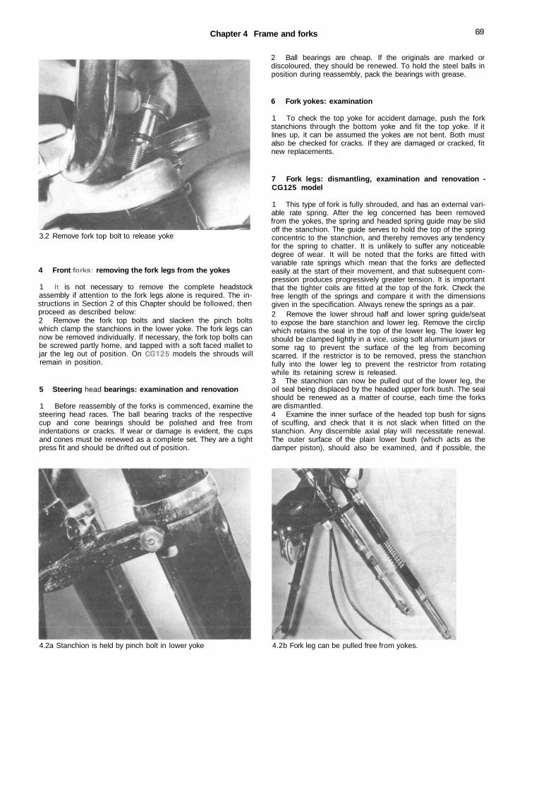
Chapter 4 Frame and forks 69
3.2 Remove fork top bolt to release yoke
4 Front forks: removing the fork legs from the yokes
1 It is not necessary to remove the complete headstockassembly if attention to the fork legs alone is required. The in-structions in Section 2 of this Chapter should be followed, thenproceed as described below:2 Remove the fork top bolts and slacken the pinch boltswhich clamp the stanchions in the lower yoke. The fork legs cannow be removed individually. If necessary, the fork top bolts canbe screwed partly home, and tapped with a soft faced mallet tojar the leg out of position. On CG125 models the shrouds willremain in position.
5 Steering head bearings: examination and renovation
1 Before reassembly of the forks is commenced, examine thesteering head races. The ball bearing tracks of the respectivecup and cone bearings should be polished and free fromindentations or cracks. If wear or damage is evident, the cupsand cones must be renewed as a complete set. They are a tightpress fit and should be drifted out of position.
2 Ball bearings are cheap. If the originals are marked ordiscoloured, they should be renewed. To hold the steel balls inposition during reassembly, pack the bearings with grease.
6 Fork yokes: examination
1 To check the top yoke for accident damage, push the forkstanchions through the bottom yoke and fit the top yoke. If itlines up, it can be assumed the yokes are not bent. Both mustalso be checked for cracks. If they are damaged or cracked, fitnew replacements.
7 Fork legs: dismantling, examination and renovation -CG125 model
1 This type of fork is fully shrouded, and has an external vari-able rate spring. After the leg concerned has been removedfrom the yokes, the spring and headed spring guide may be slidoff the stanchion. The guide serves to hold the top of the springconcentric to the stanchion, and thereby removes any tendencyfor the spring to chatter. It is unlikely to suffer any noticeabledegree of wear. It will be noted that the forks are fitted withvariable rate springs which mean that the forks are deflectedeasily at the start of their movement, and that subsequent com-pression produces progressively greater tension. It is importantthat the tighter coils are fitted at the top of the fork. Check thefree length of the springs and compare it with the dimensionsgiven in the specification. Always renew the springs as a pair.2 Remove the lower shroud half and lower spring guide/seatto expose the bare stanchion and lower leg. Remove the circlipwhich retains the seal in the top of the lower leg. The lower legshould be clamped lightly in a vice, using soft aluminium jaws orsome rag to prevent the surface of the leg from becomingscarred. If the restrictor is to be removed, press the stanchionfully into the lower leg to prevent the restrictor from rotatingwhile its retaining screw is released.3 The stanchion can now be pulled out of the lower leg, theoil seal being displaced by the headed upper fork bush. The sealshould be renewed as a matter of course, each time the forksare dismantled.4 Examine the inner surface of the headed top bush for signsof scuffing, and check that it is not slack when fitted on thestanchion. Any discernible axial play will necessitate renewal.The outer surface of the plain lower bush (which acts as thedamper piston), should also be examined, and if possible, the
4.2a Stanchion is held by pinch bolt in lower yoke 4.2b Fork leg can be pulled free from yokes.
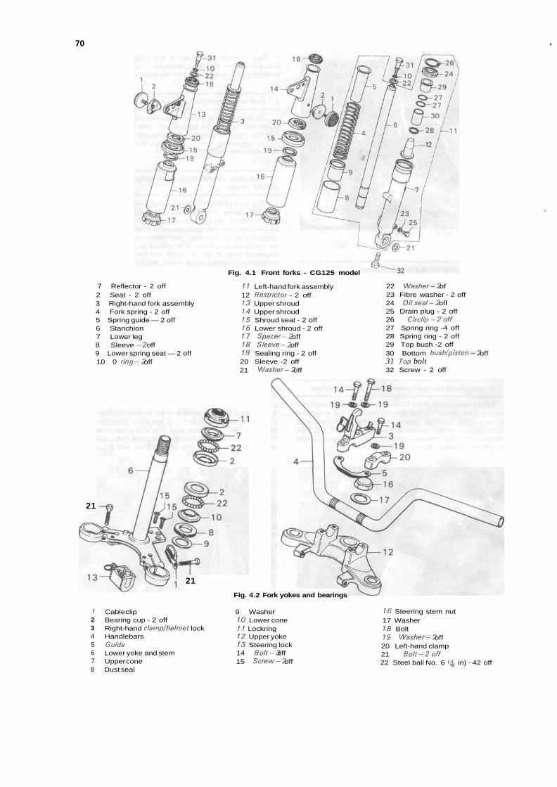
70 '
>.
7 Reflector - 2 off2 Seat - 2 off3 Right-hand fork assembly4 Fork spring - 2 off5 Spring guide — 2 off6 Stanchion7 Lower leg8 Sleeve -2 off9 Lower spring seat — 2 off10 0 ring-2 off
Fig. 4.1 Front forks - CG125 model
11 Left-hand fork assembly12 Restrictor - 2 off13 Upper shroud14 Upper shroud15 Shroud seat - 2 off16 Lower shroud - 2 off17 Spacer-2 off18 Sleeve-2 off19 Sealing ring - 2 off20 Sleeve -2 off21 Washer-2 off
22 Washer-2 of23 Fibre washer - 2 off24 Oil seal-2 off25 Drain plug - 2 off26 Circlip-2off27 Spring ring -4 off28 Spring ring - 2 off29 Top bush -2 off30 Bottom bush/piston-2 off31 Top bolt32 Screw - 2 off
21
21
Fig. 4.2 Fork yokes and bearings
72345678
Cable clipBearing cup - 2 offRight-hand clamp/helmet lockHandlebarsGuideLower yoke and stemUpper coneDust seal
9 Washer10 Lower cone11 Lockring12 Upper yoke13 Steering lock14 Bolt-3 off15 Screw-2 off
16 Steering stem nut17 Washer18 Bolt19 Washer-2 off20 Left-hand clamp21 Bolt-2off22 Steel ball No. 6 (fc in) - 42 off
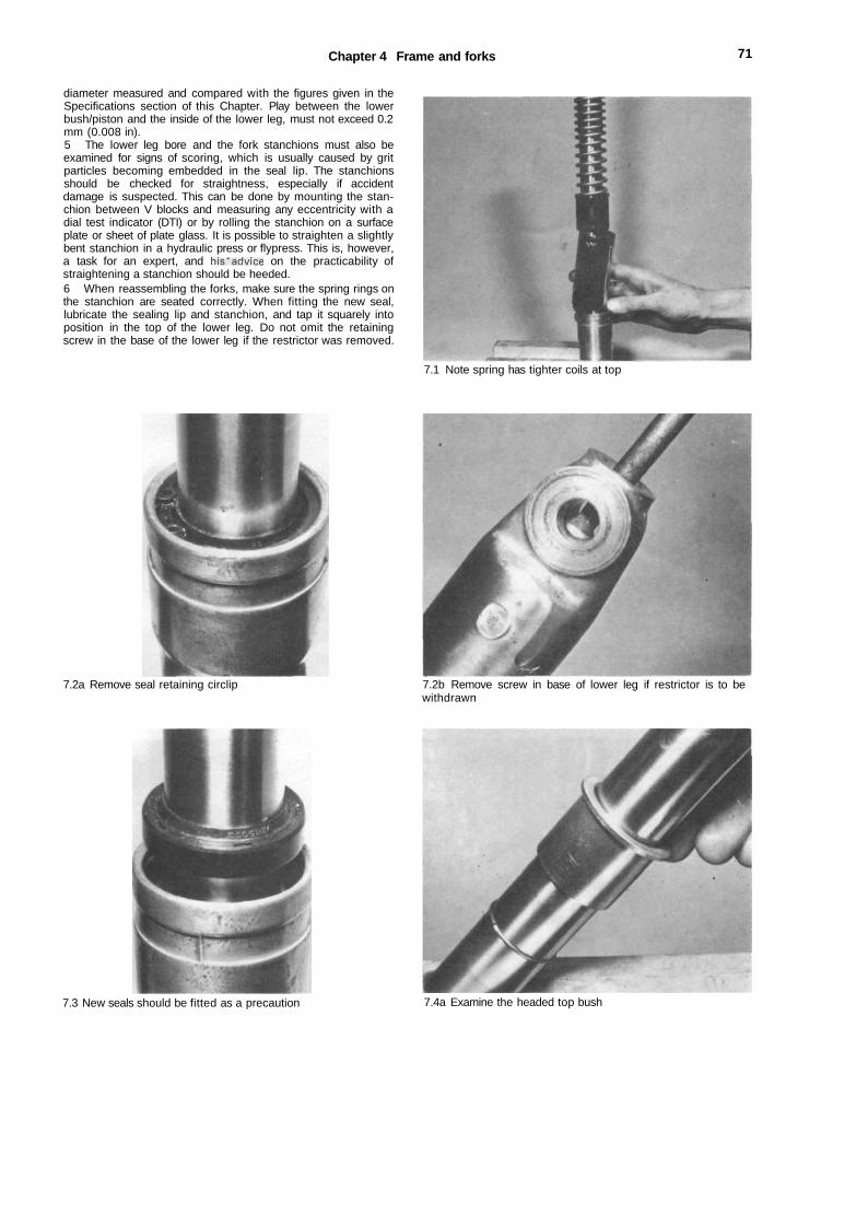
Chapter 4 Frame and forks 71
diameter measured and compared with the figures given in theSpecifications section of this Chapter. Play between the lowerbush/piston and the inside of the lower leg, must not exceed 0.2mm (0.008 in).5 The lower leg bore and the fork stanchions must also beexamined for signs of scoring, which is usually caused by gritparticles becoming embedded in the seal lip. The stanchionsshould be checked for straightness, especially if accidentdamage is suspected. This can be done by mounting the stan-chion between V blocks and measuring any eccentricity with adial test indicator (DTI) or by rolling the stanchion on a surfaceplate or sheet of plate glass. It is possible to straighten a slightlybent stanchion in a hydraulic press or flypress. This is, however,a task for an expert, and his'advice on the practicability ofstraightening a stanchion should be heeded.6 When reassembling the forks, make sure the spring rings onthe stanchion are seated correctly. When fitting the new seal,lubricate the sealing lip and stanchion, and tap it squarely intoposition in the top of the lower leg. Do not omit the retainingscrew in the base of the lower leg if the restrictor was removed.
7.1 Note spring has tighter coils at top
7.2a Remove seal retaining circlip 7.2b Remove screw in base of lower leg if restrictor is to bewithdrawn
7.3 New seals should be fitted as a precaution 7.4a Examine the headed top bush
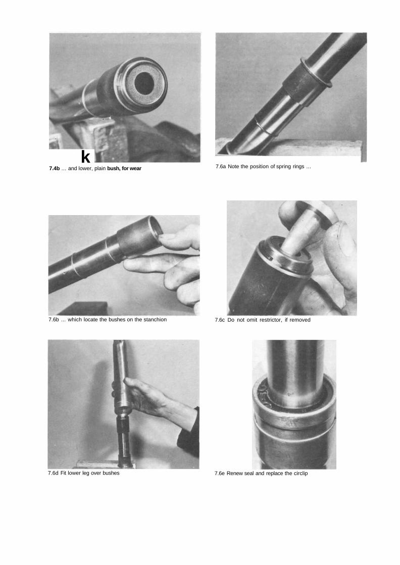
k7.4b ... and lower, plain bush, for wear 7.6a Note the position of spring rings ...
7.6b ... which locate the bushes on the stanchion 7.6c Do not omit restrictor, if removed
7.6d Fit lower leg over bushes 7.6e Renew seal and replace the circlip
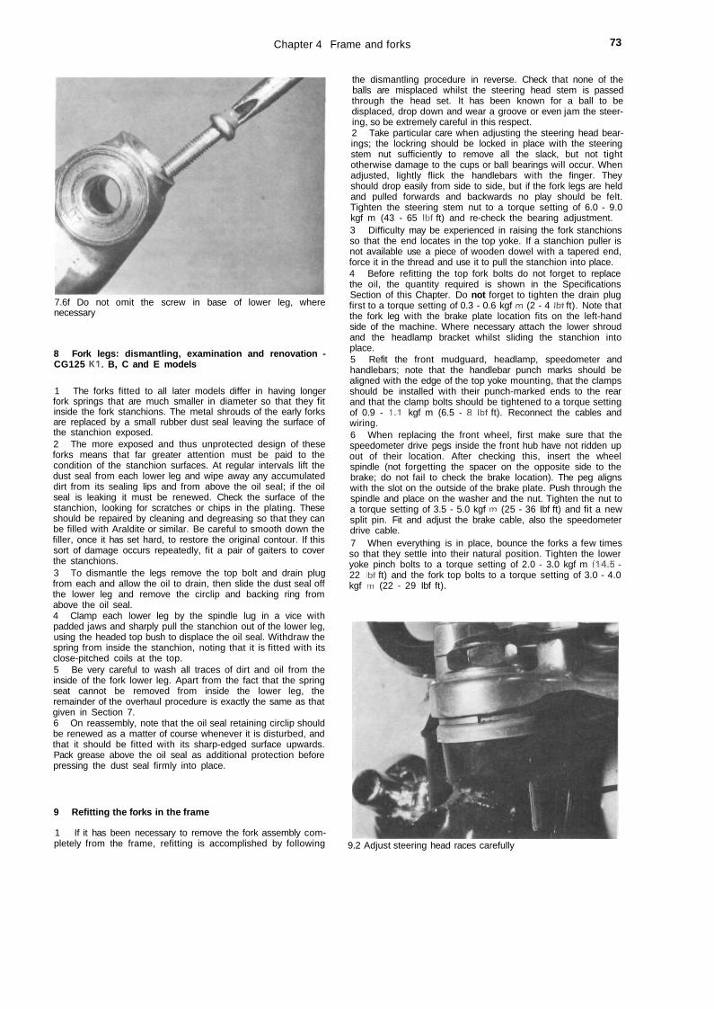
Chapter 4 Frame and forks 73
7.6f Do not omit the screw in base of lower leg, wherenecessary
8 Fork legs: dismantling, examination and renovation -CG125 K1. B, C and E models
1 The forks fitted to all later models differ in having longerfork springs that are much smaller in diameter so that they fitinside the fork stanchions. The metal shrouds of the early forksare replaced by a small rubber dust seal leaving the surface ofthe stanchion exposed.2 The more exposed and thus unprotected design of theseforks means that far greater attention must be paid to thecondition of the stanchion surfaces. At regular intervals lift thedust seal from each lower leg and wipe away any accumulateddirt from its sealing lips and from above the oil seal; if the oilseal is leaking it must be renewed. Check the surface of thestanchion, looking for scratches or chips in the plating. Theseshould be repaired by cleaning and degreasing so that they canbe filled with Araldite or similar. Be careful to smooth down thefiller, once it has set hard, to restore the original contour. If thissort of damage occurs repeatedly, fit a pair of gaiters to coverthe stanchions.3 To dismantle the legs remove the top bolt and drain plugfrom each and allow the oil to drain, then slide the dust seal offthe lower leg and remove the circlip and backing ring fromabove the oil seal.4 Clamp each lower leg by the spindle lug in a vice withpadded jaws and sharply pull the stanchion out of the lower leg,using the headed top bush to displace the oil seal. Withdraw thespring from inside the stanchion, noting that it is fitted with itsclose-pitched coils at the top.5 Be very careful to wash all traces of dirt and oil from theinside of the fork lower leg. Apart from the fact that the springseat cannot be removed from inside the lower leg, theremainder of the overhaul procedure is exactly the same as thatgiven in Section 7.6 On reassembly, note that the oil seal retaining circlip shouldbe renewed as a matter of course whenever it is disturbed, andthat it should be fitted with its sharp-edged surface upwards.Pack grease above the oil seal as additional protection beforepressing the dust seal firmly into place.
9 Refitting the forks in the frame
1 If it has been necessary to remove the fork assembly com-pletely from the frame, refitting is accomplished by following
the dismantling procedure in reverse. Check that none of theballs are misplaced whilst the steering head stem is passedthrough the head set. It has been known for a ball to bedisplaced, drop down and wear a groove or even jam the steer-ing, so be extremely careful in this respect.2 Take particular care when adjusting the steering head bear-ings; the lockring should be locked in place with the steeringstem nut sufficiently to remove all the slack, but not tightotherwise damage to the cups or ball bearings will occur. Whenadjusted, lightly flick the handlebars with the finger. Theyshould drop easily from side to side, but if the fork legs are heldand pulled forwards and backwards no play should be felt.Tighten the steering stem nut to a torque setting of 6.0 - 9.0kgf m (43 - 65 Ibf ft) and re-check the bearing adjustment.3 Difficulty may be experienced in raising the fork stanchionsso that the end locates in the top yoke. If a stanchion puller isnot available use a piece of wooden dowel with a tapered end,force it in the thread and use it to pull the stanchion into place.4 Before refitting the top fork bolts do not forget to replacethe oil, the quantity required is shown in the SpecificationsSection of this Chapter. Do not forget to tighten the drain plugfirst to a torque setting of 0.3 - 0.6 kgf m (2 - 4 Ibt ft). Note thatthe fork leg with the brake plate location fits on the left-handside of the machine. Where necessary attach the lower shroudand the headlamp bracket whilst sliding the stanchion intoplace.5 Refit the front mudguard, headlamp, speedometer andhandlebars; note that the handlebar punch marks should bealigned with the edge of the top yoke mounting, that the clampsshould be installed with their punch-marked ends to the rearand that the clamp bolts should be tightened to a torque settingof 0.9 - 1.1 kgf m (6.5 - 8 Ibf ft). Reconnect the cables andwiring.6 When replacing the front wheel, first make sure that thespeedometer drive pegs inside the front hub have not ridden upout of their location. After checking this, insert the wheelspindle (not forgetting the spacer on the opposite side to thebrake; do not fail to check the brake location). The peg alignswith the slot on the outside of the brake plate. Push through thespindle and place on the washer and the nut. Tighten the nut toa torque setting of 3.5 - 5.0 kgf m (25 - 36 Ibf ft) and fit a newsplit pin. Fit and adjust the brake cable, also the speedometerdrive cable.7 When everything is in place, bounce the forks a few timesso that they settle into their natural position. Tighten the loweryoke pinch bolts to a torque setting of 2.0 - 3.0 kgf m (14.5 -22 Ibf ft) and the fork top bolts to a torque setting of 3.0 - 4.0kgf m (22 - 29 Ibf ft).
9.2 Adjust steering head races carefully
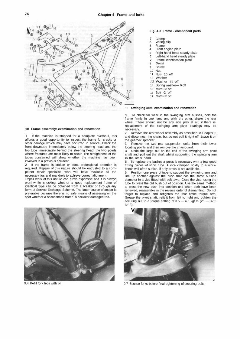
74 Chapter 4 Frame and forks
V Fig. 4.3 Frame - component parts
11
10 Frame assembly: examination and renovation
1 If the machine is stripped for a complete overhaul, thisaffords a good opportunity to inspect the frame for cracks orother damage which may have occurred in service. Check thefront downtube immediately below the steering head and thetop tube immediately behind the steering head, the two pointswhere fractures are most likely to occur. The straightness of thetubes concerned will show whether the machine has beeninvolved in a previous accident.2 If the frame is broken or bent, professional attention isrequired. Repairs of this nature should be entrusted to a com-petent repair specialist, who will have available all thenecessary jigs and mandrels to achieve correct alignment.Repair work of this nature can prove expensive and it is alwaysworthwhile checking whether a good replacement frame ofidentical type can be obtained from a breaker or through anyform of Service Exchange Scheme. The latter course of action ispreferable because there is no safe means of assessing on thespot whether a secondhand frame is accident damaged too.
7234567891011121314151617
ClampWiring clipFrameFront engine plateRight-hand head steady plateLeft-hand head steady plateFrame identification plateDecalScrewNutNut- 10 offWasherWasher- 11 offSpring washer— 6 offBolt-2 offBolt -2 offBolt-2 off
11 Swinging arm: examination and renovation
1 To check for wear in the swinging arm bushes, hold theframe firmly in one hand and with the other, shake the rearwheel. There should not be any side play at all; if there is,replacement of the swinging arm pivot bearings may benecessary.2 Remove the rear wheel assembly as described in Chapter 5and disconnect the chain, but do not pull it right off. Leave it onthe gearbox sprocket.3 Remove the two rear suspension units from their lowerlocating points and then remove the chainguard.4 Undo the large nut on the end of the swinging arm pivotshaft and pull out the shaft whilst supporting the swinging armin the other hand.5 To replace the bushes a press is necessary with a few goodfitting pieces of short tube. A vice clamped rigidly to a work-bench will often suffice, if a fly-press is not available.6 Position one piece of tube to support the swinging arm andline up another against the bush that has the same outsidediameter in a vice fitted with soft jaws. Close the vice, using thetube to press the old bush out of position. Use the same methodto press the new bush into position and when both have beenrenewed, reassemble in the reverse order of dismantling. Do notforget to replace and retighten the rear brake torque arm.Grease the pivot shaft, refit it from left to right and tighten thesecuring nut to a torque setting of 3.5 — 4.5 kgf m (25 — 32.5Ibf ft).
V
9.4 Refill fork legs with oil 9.7 Bounce forks before final tightening of securing bolts
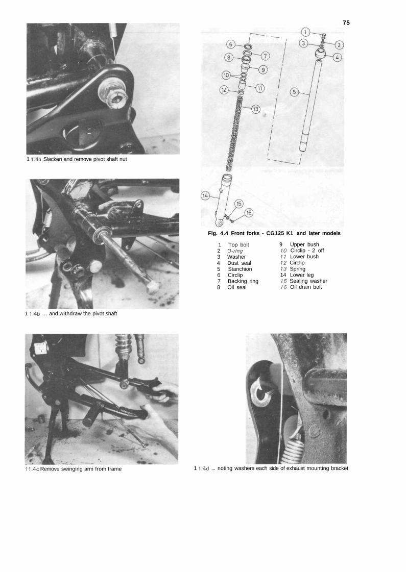
1 1.4a Slacken and remove pivot shaft nut
75
Fig. 4.4 Front forks - CG125 K1 and later models
1 Top bolt2 O-ring3 Washer4 Dust seal5 Stanchion6 Circlip7 Backing ring8 Oil seal
9 Upper bush10 Circlip - 2 off11 Lower bush12 Circlip13 Spring14 Lower leg15 Sealing washer16 Oil drain bolt
1 1.4b ... and withdraw the pivot shaft
11.4c Remove swinging arm from frame 1 1,4d ... noting washers each side of exhaust mounting bracket
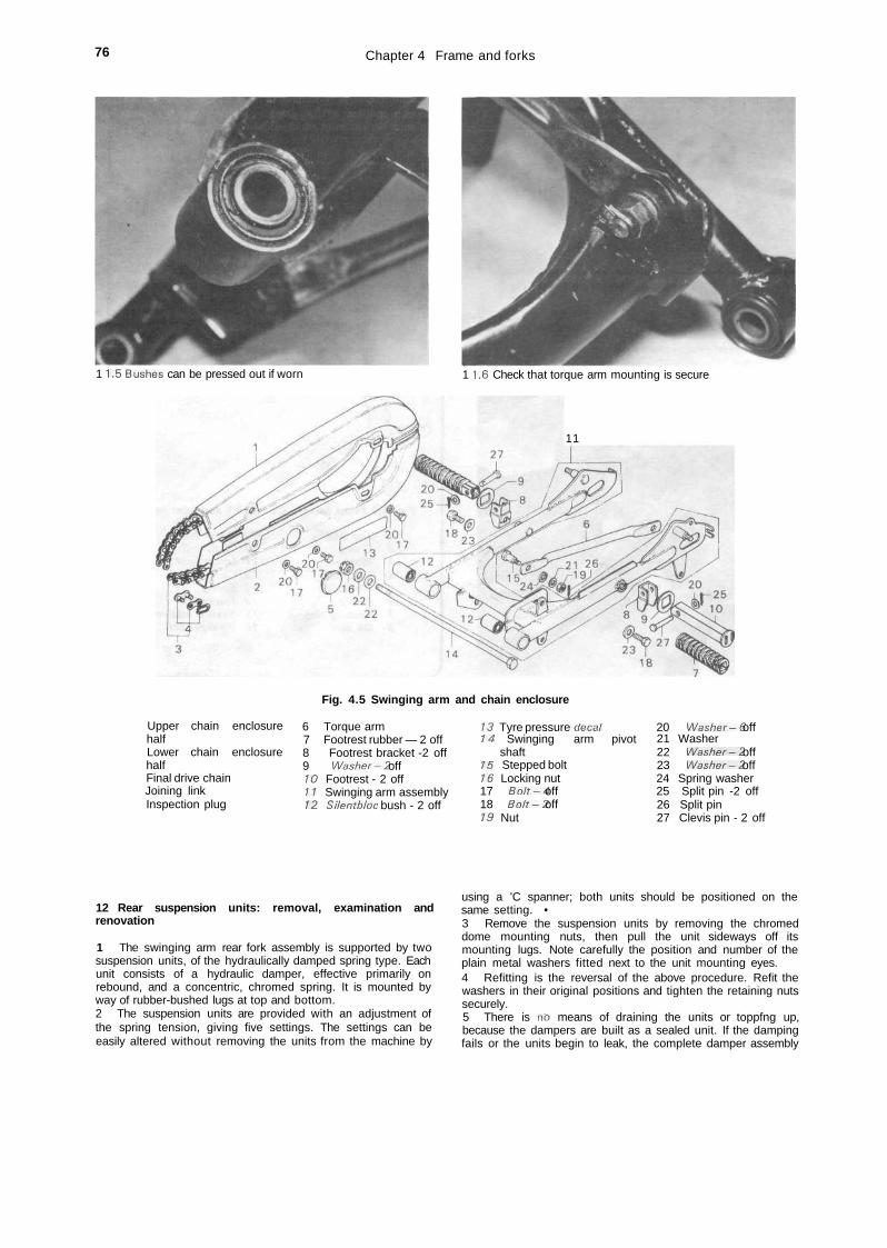
76 Chapter 4 Frame and forks
1 1.5 Bushes can be pressed out if worn 1 1.6 Check that torque arm mounting is secure
1 1
Fig. 4.5 Swinging arm and chain enclosure
Upper chain enclosurehalfLower chain enclosurehalfFinal drive chainJoining linkInspection plug
6 Torque arm7 Footrest rubber — 2 off8 Footrest bracket -2 off9 Washer-2 off10 Footrest - 2 off11 Swinging arm assembly12 Silentbloc bush - 2 off
13 Tyre pressure decal14 Swinging arm pivot
shaft15 Stepped bolt16 Locking nut17 Bolt-4 off18 Bolt-2 off19 Nut
20 Washer-6 off21 Washer22 Washer-2 off23 Washer-2 off24 Spring washer25 Split pin -2 off26 Split pin27 Clevis pin - 2 off
12 Rear suspension units: removal, examination andrenovation
1 The swinging arm rear fork assembly is supported by twosuspension units, of the hydraulically damped spring type. Eachunit consists of a hydraulic damper, effective primarily onrebound, and a concentric, chromed spring. It is mounted byway of rubber-bushed lugs at top and bottom.2 The suspension units are provided with an adjustment ofthe spring tension, giving five settings. The settings can beeasily altered without removing the units from the machine by
using a 'C spanner; both units should be positioned on thesame setting. •3 Remove the suspension units by removing the chromeddome mounting nuts, then pull the unit sideways off itsmounting lugs. Note carefully the position and number of theplain metal washers fitted next to the unit mounting eyes.4 Refitting is the reversal of the above procedure. Refit thewashers in their original positions and tighten the retaining nutssecurely.5 There is no means of draining the units or toppfng up,because the dampers are built as a sealed unit. If the dampingfails or the units begin to leak, the complete damper assembly
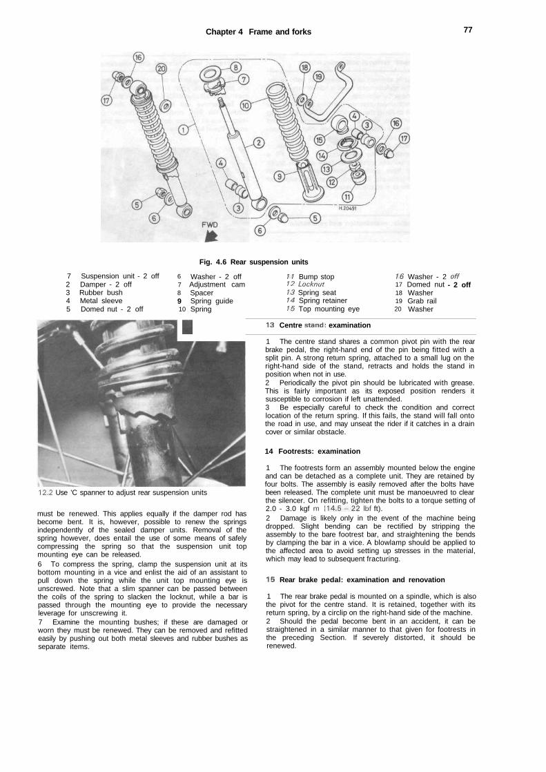
Chapter 4 Frame and forks 77
Fig. 4.6 Rear suspension units
7 Suspension unit - 2 off2 Damper - 2 off3 Rubber bush4 Metal sleeve5 Domed nut - 2 off
678910
I
Washer - 2 offAdjustment camSpacerSpring guideSpring
11 Bump stop12 Locknut13 Spring seat14 Spring retainer15 Top mounting eye
13 Centre stand: examination
1617181920
Washer - 2Domed nutWasherGrab railWasher
off- 2 off
12.2 Use 'C spanner to adjust rear suspension units
must be renewed. This applies equally if the damper rod hasbecome bent. It is, however, possible to renew the springsindependently of the sealed damper units. Removal of thespring however, does entail the use of some means of safelycompressing the spring so that the suspension unit topmounting eye can be released.6 To compress the spring, clamp the suspension unit at itsbottom mounting in a vice and enlist the aid of an assistant topull down the spring while the unit top mounting eye isunscrewed. Note that a slim spanner can be passed betweenthe coils of the spring to slacken the locknut, while a bar ispassed through the mounting eye to provide the necessaryleverage for unscrewing it.7 Examine the mounting bushes; if these are damaged orworn they must be renewed. They can be removed and refittedeasily by pushing out both metal sleeves and rubber bushes asseparate items.
1 The centre stand shares a common pivot pin with the rearbrake pedal, the right-hand end of the pin being fitted with asplit pin. A strong return spring, attached to a small lug on theright-hand side of the stand, retracts and holds the stand inposition when not in use.2 Periodically the pivot pin should be lubricated with grease.This is fairly important as its exposed position renders itsusceptible to corrosion if left unattended.3 Be especially careful to check the condition and correctlocation of the return spring. If this fails, the stand will fall ontothe road in use, and may unseat the rider if it catches in a draincover or similar obstacle.
14 Footrests: examination
1 The footrests form an assembly mounted below the engineand can be detached as a complete unit. They are retained byfour bolts. The assembly is easily removed after the bolts havebeen released. The complete unit must be manoeuvred to clearthe silencer. On refitting, tighten the bolts to a torque setting of2.0 - 3.0 kgf m ( 1 4 . 5 - 2 2 Ibf ft).2 Damage is likely only in the event of the machine beingdropped. Slight bending can be rectified by stripping theassembly to the bare footrest bar, and straightening the bendsby clamping the bar in a vice. A blowlamp should be applied tothe affected area to avoid setting up stresses in the material,which may lead to subsequent fracturing.
15 Rear brake pedal: examination and renovation
1 The rear brake pedal is mounted on a spindle, which is alsothe pivot for the centre stand. It is retained, together with itsreturn spring, by a circlip on the right-hand side of the machine.2 Should the pedal become bent in an accident, it can bestraightened in a similar manner to that given for footrests inthe preceding Section. If severely distorted, it should berenewed.
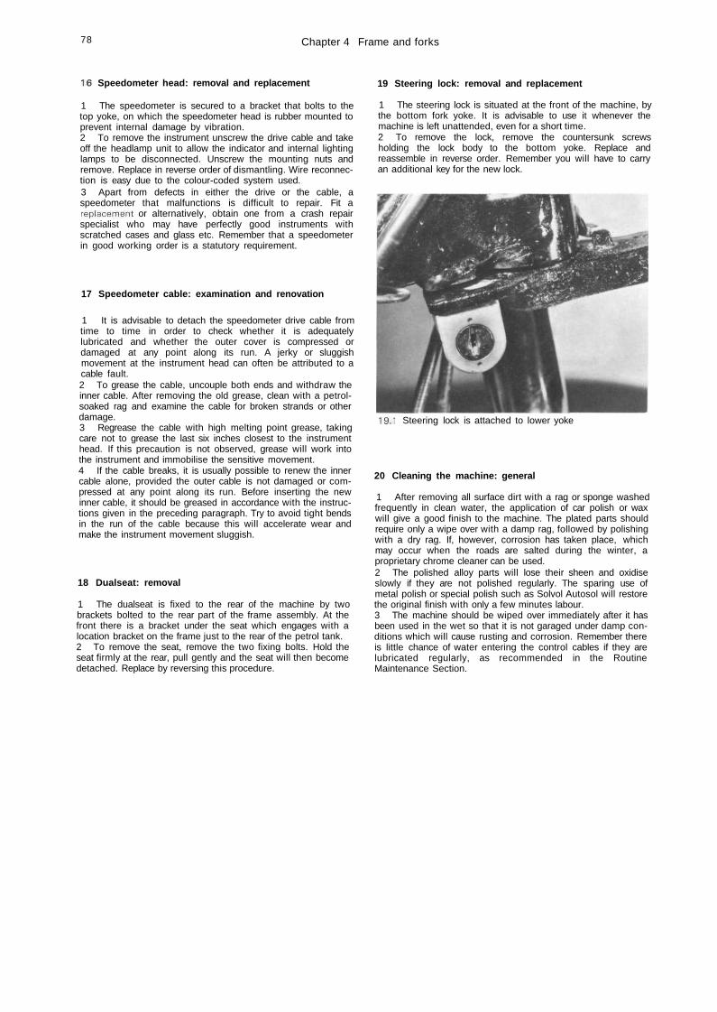
78 Chapter 4 Frame and forks
16 Speedometer head: removal and replacement
1 The speedometer is secured to a bracket that bolts to thetop yoke, on which the speedometer head is rubber mounted toprevent internal damage by vibration.2 To remove the instrument unscrew the drive cable and takeoff the headlamp unit to allow the indicator and internal lightinglamps to be disconnected. Unscrew the mounting nuts andremove. Replace in reverse order of dismantling. Wire reconnec-tion is easy due to the colour-coded system used.3 Apart from defects in either the drive or the cable, aspeedometer that malfunctions is difficult to repair. Fit areplacement or alternatively, obtain one from a crash repairspecialist who may have perfectly good instruments withscratched cases and glass etc. Remember that a speedometerin good working order is a statutory requirement.
17 Speedometer cable: examination and renovation
1 It is advisable to detach the speedometer drive cable fromtime to time in order to check whether it is adequatelylubricated and whether the outer cover is compressed ordamaged at any point along its run. A jerky or sluggishmovement at the instrument head can often be attributed to acable fault.2 To grease the cable, uncouple both ends and withdraw theinner cable. After removing the old grease, clean with a petrol-soaked rag and examine the cable for broken strands or otherdamage.3 Regrease the cable with high melting point grease, takingcare not to grease the last six inches closest to the instrumenthead. If this precaution is not observed, grease will work intothe instrument and immobilise the sensitive movement.4 If the cable breaks, it is usually possible to renew the innercable alone, provided the outer cable is not damaged or com-pressed at any point along its run. Before inserting the newinner cable, it should be greased in accordance with the instruc-tions given in the preceding paragraph. Try to avoid tight bendsin the run of the cable because this will accelerate wear andmake the instrument movement sluggish.
18 Dualseat: removal
1 The dualseat is fixed to the rear of the machine by twobrackets bolted to the rear part of the frame assembly. At thefront there is a bracket under the seat which engages with alocation bracket on the frame just to the rear of the petrol tank.2 To remove the seat, remove the two fixing bolts. Hold theseat firmly at the rear, pull gently and the seat will then becomedetached. Replace by reversing this procedure.
19 Steering lock: removal and replacement
1 The steering lock is situated at the front of the machine, bythe bottom fork yoke. It is advisable to use it whenever themachine is left unattended, even for a short time.2 To remove the lock, remove the countersunk screwsholding the lock body to the bottom yoke. Replace andreassemble in reverse order. Remember you will have to carryan additional key for the new lock.
19.1 Steering lock is attached to lower yoke
20 Cleaning the machine: general
1 After removing all surface dirt with a rag or sponge washedfrequently in clean water, the application of car polish or waxwill give a good finish to the machine. The plated parts shouldrequire only a wipe over with a damp rag, followed by polishingwith a dry rag. If, however, corrosion has taken place, whichmay occur when the roads are salted during the winter, aproprietary chrome cleaner can be used.2 The polished alloy parts will lose their sheen and oxidiseslowly if they are not polished regularly. The sparing use ofmetal polish or special polish such as Solvol Autosol will restorethe original finish with only a few minutes labour.3 The machine should be wiped over immediately after it hasbeen used in the wet so that it is not garaged under damp con-ditions which will cause rusting and corrosion. Remember thereis little chance of water entering the control cables if they arelubricated regularly, as recommended in the RoutineMaintenance Section.

21 Fault diagnosis:
Symptom
frame and forks
Cause
Chapter 4 Frame and forks /»
Remedy
Machine veers either to the leftor the right with hands offhandlebars
Machine rolls at low speed
Machine judders when frontbrake is applied
Machine pitches on unevensurfaces
Fork action stiff
Machine wanders. Steeringimprecise. Rear wheel tends to hop.
Bent frameTwisted forksWheels out of alignment
Overtight steering head bearings
Slack steering head bearingsWorn fork bushes
Ineffective fork dampersIneffective rear suspension units
Suspension too soft
Fork legs out of alignment (twisted in yokes)
Worn swinging arm pivot
Check, and renew.Check, and renew.Check and realign.
Slacken until adjustment is correct.
Tighten, until adjustment is correct.Dismantle forks and renew bushes.
Check oil content of front forks.Check whether units still have dampingaction.Raise suspension unit adjustment one notch.
Slacken yoke clamps, and fork top bolts.Pump fork several times then retighten frombottom upwards.
Dismantle and renew bushes and pivot shaft.
Chapter 5 Wheels, brakes and tyresRefer to Chapter 7 for information relating to the 1985 on Brazilian models
Contents
.
General description 1Front wheel : examination and renovation 2Front wheel: removal 3Front brake: examination and renovation 4Adjusting the front brake 5Front wheel bearings: removal and replacement 6Front wheel : replacement 7Rear wheel : examination 8Rear wheel : removal 9
Rear brake : examination and renovation 10Rear wheel bearings : removal and replacement ... 11Rear sprocket and shock absorber rubbers : examinationand renovation 12Adjusting the rear brake 13Final drive chain : examination, adjustment and lubrication 14Rear wheel: replacement 15Tyres : removal and replacement 16Fault diagnosis 17
Specifications
WheelsRim size
Front 1.40x18Rear 1.60x17
Rim maximum runout — radial and axial 2.0 mm (0.0787 in)Spindle maximum warpage 0.2 mm (0.0079 in)
Brakes StandardDrum inside diameter 1 10 mm (4.3307 in)Brake shoe friction material thickness 3.9 - 4.1 mm
(0.1535 - 0.1614 in)
Tyres FrontSize ... 2 . 5 0 - 1 8 4PRPressures — tyres cold
Solo 25 psi (1.75 kg/cm2)Pillion 25 psi (1.75 kg/cm2)
Manufacturer's recommended minimum tread depth 1.5 mm (0.06 in)
Wear limit1 1 1 mm (4.3701 in)2.0 mm (0.0787 in)
Rear3 . 0 0 - 17 6PR
28 psi (2.00 kg/cm2)40 psi (2.80 kg/cm2)2.0 mm (0.08 in)
1 General description
All machines are equipped with two identical single leadingshoe (sis) brake units, the drums being integral with the wheelhub.
On all models, chromium plated steel wheel rims are lacedto the hub by spokes, the front and rear rims being of 18 in and17 in diameter respectively. The front rim carries a 2-50 insection tyre, while the rear fitment is of 3 0 0 in section.
2 Front wheel: examination and renovation
1 Place the machine on the centre stand so that the frontwheel is raised clear of the ground. Spin the wheel and checkthe rim alignment. Small irregularities can be corrected by
tightening the spokes in the affected area, although a certainamount of practice is necessary to prevent over-correction. Anyflats in the wheel rim should be evident at the same time. Theseare more difficult to remove and in most cases it will benecessary to have the wheel rebuilt on a new rim. Apart fromthe effect on stability, a flat will expose the tyre bead and wallsto greater risk of damage.2 Check for loose or broken spokes. Tapping the spokes is thebest guide to tension. A loose spoke will produce a quitedifferent sound and should be tightened by turning the nipple inan anti-clockwise direction. Always re-check for run-out byspinning the wheel again. If the spokes have to be tightened anexcessive amount, it is advisable to remove the tyre and tube bythe procedure detailed in Section 16 of this Chapter; this is sothat the protruding ends of the spokes can be ground off, toprevent them from chafing the inner tube and causingpunctures.

Chapter 5 Wheels, brakes and tyres 81
3 Front wheel: removal
1 With the machine supported on the centre stand, block thestand and crankcase to raise the wheel clear of the ground.2 Detach the speedometer drive cable at the wheel, by un-screwing the knurled gland nut which retains it. Remove thefront brake cable.3 Remove the wheel spindle nut and split pin, and withdrawthe spindle with the aid of a tommy bar. The wheel can now belowered clear of the forks and put to one side.
4 Front brake: examination and renovation
1 With the wheel removed from the forks, as described in thepreceding Section, the brake plate assembly can be removedfrom the drum.2 Examine the drum surface for signs of scoring or oil con-tamination. Both of these conditions will impair brakingefficiency. Remove all traces of dust, preferably using a brasswire brush, taking care not to inhale any of it, as it is of anasbestos nature, and consequently harmful. Remove oil orgrease deposits, using a petrol soaked rag.3 If deep scoring is evident, due to the linings having wornthrough to the shoe at some time, the drum must be skimmedon a lathe, or renewed. Whilst there are firms who willundertake to skim a drum whilst fitted to the wheel, it should be
borne in mind that excessive skimming will change the radius ofthe drum in relation to the brake shoes, therefore reducing thefriction area until extensive bedding in has taken place. Also fulladjustment of the shoes may not be possible. If in doubt aboutthis point, the advice of one of the specialist engineering firmswho undertake this work should be sought.4 If fork oil or grease from the wheel bearings has badly con-taminated the linings, they should be renewed. There is nosatisfactory way of degreasing the lining material, which in anycase is relatively cheap to replace. Measure the thickness of thefriction material; if it is worn at any point to or beyond thespecified wear limit, both shoes must be renewed immediately.It is a false economy to try to cut corners with brakecomponents; the whole safety of both machine and rider beingdependent on their good condition.5 The linings are bonded to the shoes, and the shoe must berenewed complete with the new linings. This is accomplishedby folding the shoes together until the spring tension is relaxed,and then lifting the shoes and springs off the brake plate. Fittingnew shoes is a direct reversal of the above procedure.6 Before refitting existing shoes, roughen the lining surfacesufficiently to break the glaze which will have formed in use.7 The camshaft can be displaced for greasing prior toreassembly, after removing the actuating lever. No furtherattention is normally required. Note the alignment marks on thecamshaft splined end, and on the lever. These must align onreassembly.
Fig. 5.1 Front wheel and brake - component parts
12345678910
Wheel spindleSpacerHubDistance pieceWheel rimTyre (2.50- 18-4PR)Inner tubeRim tapeSpeedometer drive gearFibre washer
11 Brake plate12 Brake shoe -2 off13 Camshaft14 Return spring -2 off15 Actuating arm16 Threaded plate17 Spring18 Castellated nut19 Washer20 Seal
21 Seal22 Bolt23 Screw24 Split pin25 Trunnion26 Adjusting nut27 Bearing-2 off28 Spoke set29 Spoke set
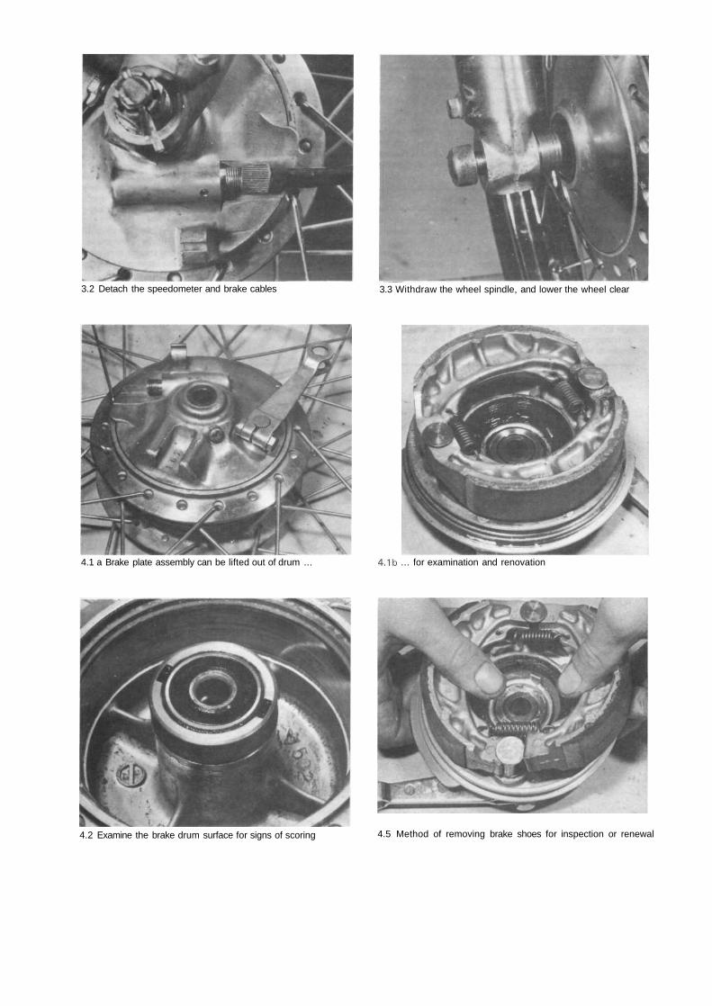
3.2 Detach the speedometer and brake cables 3.3 Withdraw the wheel spindle, and lower the wheel clear
4.1 a Brake plate assembly can be lifted out of drum ... 4.1b ... for examination and renovation
4.2 Examine the brake drum surface for signs of scoring 4.5 Method of removing brake shoes for inspection or renewal
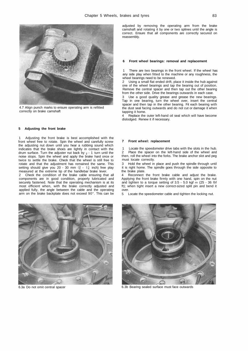
Chapter 5 Wheels, brakes and tyres 83
4.7 Align punch marks to ensure operating arm is refittedcorrectly on brake camshaft
adjusted by removing the operating arm from the brakecamshaft and rotating it by one or two splines until the angle iscorrect. Ensure that all components are correctly secured onreassembly.
6 Front wheel bearings: removal and replacement
1 There are two bearings in the front wheel. If the wheel hasany side play when fitted to the machine or any roughness, thewheel bearings need to be renewed.2 Using a small flat ended drift, place it inside the hub againstone of the wheel bearings and tap the bearing out of position.Remove the central spacer and then tap out the other bearingfrom the other side. Drive the bearings outwards in each case.3 Use a good quality grease and grease the new bearings.Tap in one bearing, turn the wheel over, insert the centralspacer and then tap in the other bearing. Fit each bearing withthe dust seal facing outwards and do not cut or damage it whentapping it home.4 Replace the outer left-hand oil seal which will have becomedislodged. Renew it if necessary.
5 Adjusting the front brake
1 Adjusting the front brake is best accomplished with thefront wheel free to rotate. Spin the wheel and carefully screwthe adjusting nut down until you hear a rubbing sound whichindicates that the brake shoes are lightly in contact with thedrum surface. Turn the adjuster nut back by y - 1 turn until thenoise stops. Spin the wheel and apply the brake hard once ortwice to settle the brake. Check that the wheel is still free torotate and that the adjustment has remained the same. Thissetting should give you 20 - 30 mm (J - 1-J inch) free playmeasured at the extreme tip of the handlebar brake lever.2 Check the condition of the brake cable ensuring that allcomponents are in good condition, properly lubricated andsecurely fastened. Note that the operating mechanism is at itsmost efficient when, with the brake correctly adjusted andapplied fully, the angle between the cable and the operatingarm on the brake backplate does not exceed 90°. This can be
7 Front wheel: replacement
1 Locate the speedometer drive tabs with the slots in the hub.2 Place the spacer on the left-hand side of the wheel andthen, roll the wheel into the forks. The brake anchor slot and pegmust locate correctly.3 Hold the wheel in place and push the spindle through untilit is right home. The spindle goes through the side opposite tothe brake plate.4 Reconnect the front brake cable and adjust the brake.Applying the front brake firmly with one hand, spin on the nutand tighten to a torque setting of 3.5 - 5.0 kgf m (25 - 36 Ibfft); when tight insert a new correct-sized split pin and bend itover.5 Locate the speedometer cable and tighten the locking nut.
6.3a Do not omit central spacer 6.3b Bearing sealed surface must face outwards
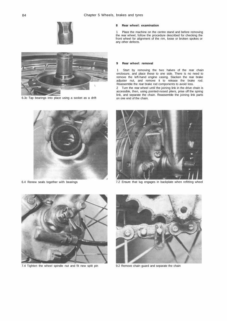
84 Chapter 5 Wheels, brakes and tyres
8 Rear wheel: examination
1 Place the machine on the centre stand and before removingthe rear wheel, follow the procedure described for checking thefront wheel for alignment of the rim, loose or broken spokes orany other defects.
\
6.3c Tap bearings into place using a socket as a drift
9 Rear wheel: removal
1 Start by removing the two halves of the rear chainenclosure, and place these to one side. There is no need toremove the left-hand engine casing. Slacken the rear brakeadjuster nut, and remove it to release the brake rod.Reassemble the rear brake rod components to avoid loss.2 Turn the rear wheel until the joining link in the drive chain isaccessible, then, using pointed-nosed pliers, prise off the springlink, and separate the chain. Reassemble the joining link partson one end of the chain.
6.4 Renew seals together with bearings 7.2 Ensure that lug engages in backplate when refitting wheel
7.4 Tighten the wheel spindle nut and fit new split pin 9.2 Remove chain guard and separate the chain
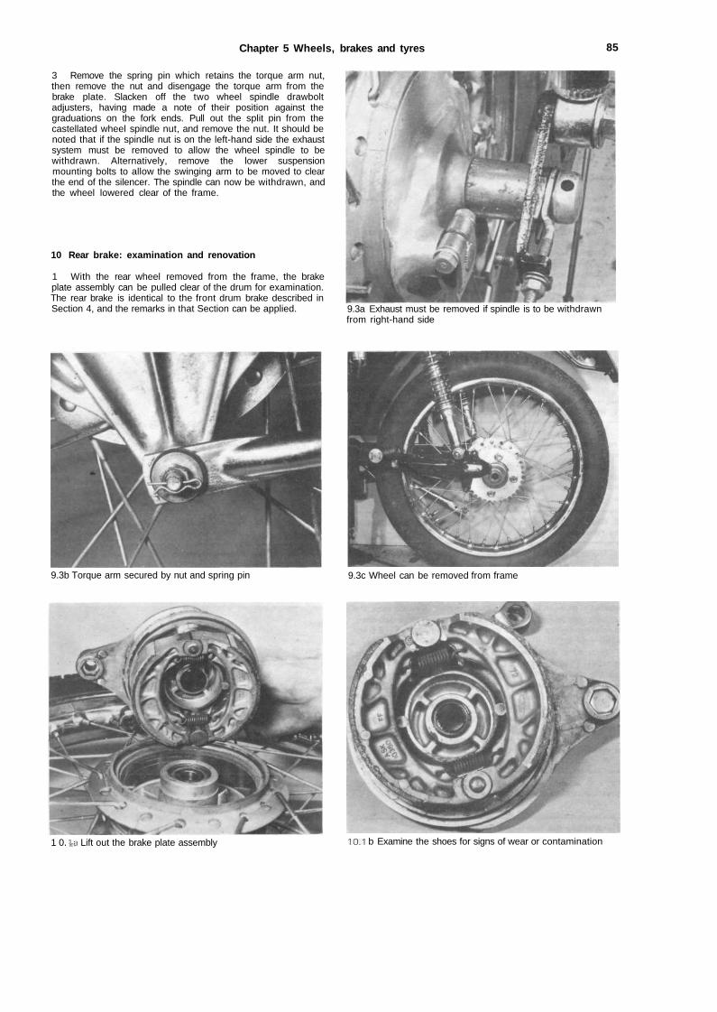
Chapter 5 Wheels, brakes and tyres 85
3 Remove the spring pin which retains the torque arm nut,then remove the nut and disengage the torque arm from thebrake plate. Slacken off the two wheel spindle drawboltadjusters, having made a note of their position against thegraduations on the fork ends. Pull out the split pin from thecastellated wheel spindle nut, and remove the nut. It should benoted that if the spindle nut is on the left-hand side the exhaustsystem must be removed to allow the wheel spindle to bewithdrawn. Alternatively, remove the lower suspensionmounting bolts to allow the swinging arm to be moved to clearthe end of the silencer. The spindle can now be withdrawn, andthe wheel lowered clear of the frame.
10 Rear brake: examination and renovation
1 With the rear wheel removed from the frame, the brakeplate assembly can be pulled clear of the drum for examination.The rear brake is identical to the front drum brake described inSection 4, and the remarks in that Section can be applied. 9.3a Exhaust must be removed if spindle is to be withdrawn
from right-hand side
9.3b Torque arm secured by nut and spring pin 9.3c Wheel can be removed from frame
1 0. \a Lift out the brake plate assembly 10.1 b Examine the shoes for signs of wear or contamination
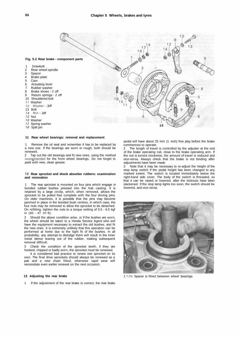
86 Chapter 5 Wheels, brakes and tyres
Fig. 5.2 Rear brake - component parts
1 Drawbolt2 Rear wheel spindle3 Spacer4 Brake plate5 Cam6 Actuating lever7 Rubber washer8 Brake shoes - 2 off9 Return springs - 2 off10 Shouldered bolt11 Washer12 Washer-2 off13 Bolt14 Nut-2 off15 Nut16 Washer17 Spring washer18 Split pin 10
11 Rear wheel bearings: removal and replacement
1 Remove the oil seal and remember it has to be replaced bya new one. If the bearings are worn or rough, both should berenewed.2 Tap out the old bearings and fit new ones, using the methodrecommended for the front wheel bearings. Do not forget topack with new, clean grease.
12 Rear sprocket and shock absorber rubbers: examinationand renovation
1 The rear sprocket is mounted on four pins which engage inbonded rubber bushes pressed into the hub casting. It isretained by a large circlip, which, when removed, allows thesprocket to be pulled free complete with the four driving pins.On older machines, it is possible that the pins may becomejammed in place in the bonded bush centres, in which case, thefour nuts may be removed to allow the sprocket to be detached.On refitting, tighten the nuts to a torque setting of 5.5 - 6.5 kgfm (40 - 47 Ibf ft).2 Should the above condition arise, or if the bushes are worn,the wheel should be taken to a Honda Service Agent who willhave the equipment necessary to extract the old bushes, and fitthe new ones. It is extremely unlikely that this operation can beperformed at home due to the tight fit of the bushes. In allprobability, any attempt to dislodge them will result in the innermetal sleeve tearing out of the rubber, making subsequentremoval difficult.3 Check the condition of the sprocket teeth, if they arehooked, chipped or badly worn, the sprocket must be renewed.
It is considered bad practice to renew one sprocket on itsown. The final drive sprockets should always be renewed as apair and a new chain fitted, otherwise rapid wear willnecessitate even earlier renewal on the next occasion.
13 Adjusting the rear brake
1 If the adjustment of the rear brake is correct, the rear brake
pedal will have about 25 mm (1 inch) free play before the brakecommences to operate.2 The length of travel is controlled by the adjuster at the endof the brake operating rod, close to the brake operating arm. Ifthe nut is turned clockwise, the amount of travel is reduced andvice-versa. Always check that the brake is not binding afteradjustments have been made.3 Note that it may be necessary to re-adjust the height of thestop lamp switch if the pedal height has been changed to anymarked extent. The switch is located immediately below theright-hand side cover. The body of the switch is threaded, sothat it can be raised or lowered, after the locknuts have beenslackened. If the stop lamp lights too soon, the switch should belowered, and vice-versa.
1 1.2a Spacer is fitted between wheel bearings
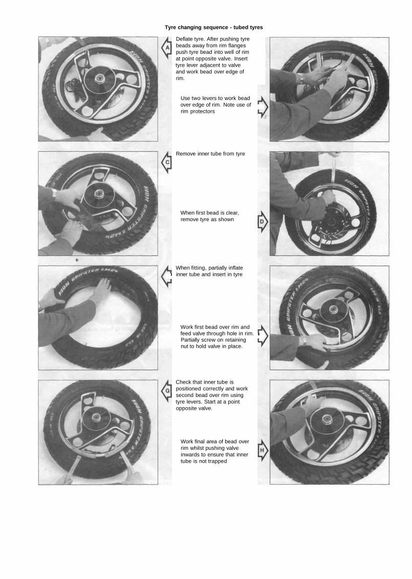
Tyre changing sequence - tubed tyres
Deflate tyre. After pushing tyrebeads away from rim flangespush tyre bead into well of rimat point opposite valve. Inserttyre lever adjacent to valveand work bead over edge ofrim.
Use two levers to work beadover edge of rim. Note use ofrim protectors
Remove inner tube from tyre
When first bead is clear,remove tyre as shown
When fitting, partially inflateI inner tube and insert in tyre
Work first bead over rim andfeed valve through hole in rim. iPartially screw on retainingnut to hold valve in place.
Check that inner tube ispositioned correctly and worksecond bead over rim usingtyre levers. Start at a pointopposite valve.
Work final area of bead overrim whilst pushing valveinwards to ensure that innertube is not trapped
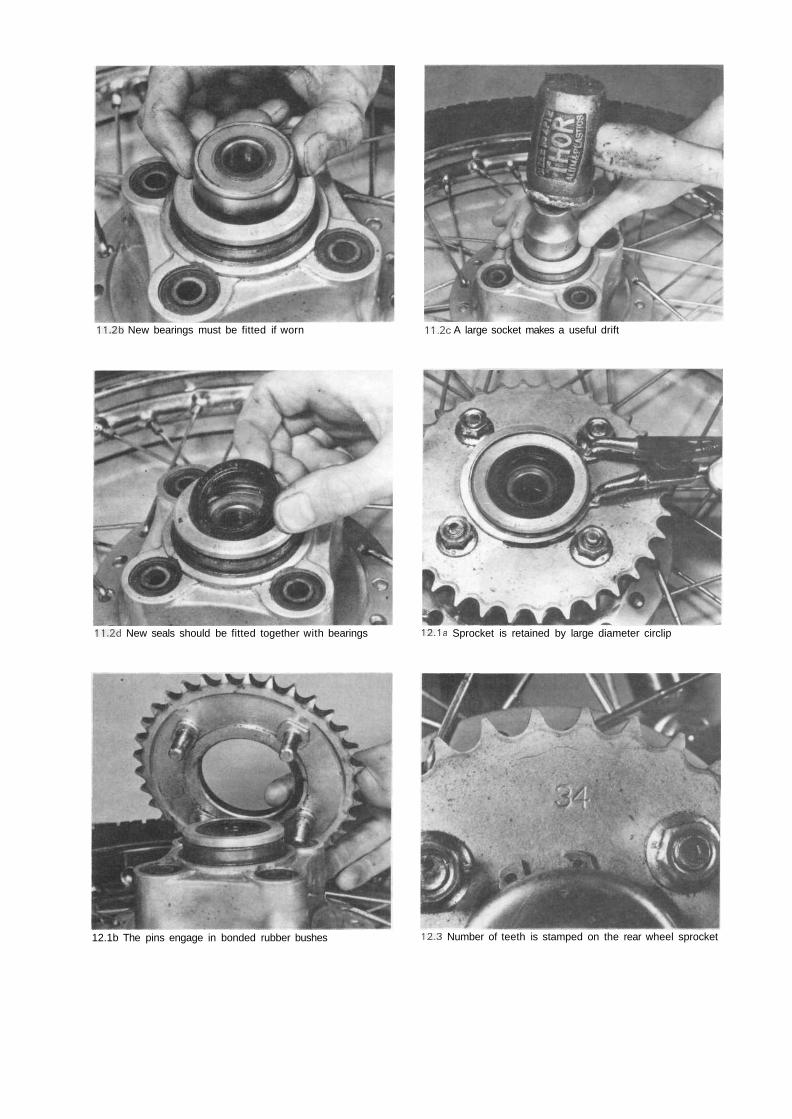
11.2b New bearings must be fitted if worn 11.2c A large socket makes a useful drift
11.2d New seals should be fitted together with bearings 12.1a Sprocket is retained by large diameter circlip
12.1b The pins engage in bonded rubber bushes 12.3 Number of teeth is stamped on the rear wheel sprocket
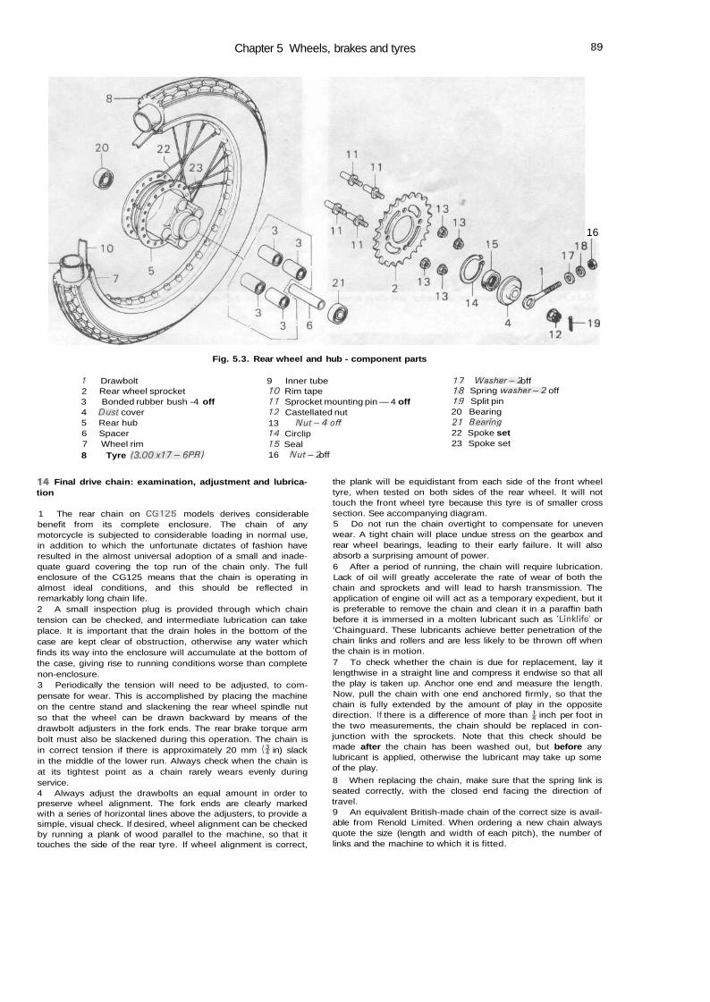
Chapter 5 Wheels, brakes and tyres 89
16
Fig. 5.3. Rear wheel and hub - component parts
/ Drawbolt2 Rear wheel sprocket3 Bonded rubber bush -4 off4 Dust cover5 Rear hub6 Spacer7 Wheel rim8 Tyre (3.00x17-6PR)
9 Inner tube10 Rim tape11 Sprocket mounting pin — 4 off12 Castellated nut13 Nut-4off14 Circlip15 Seal16 Nut-2 off
17 Washer-2 off18 Spring washer—2 off19 Split pin20 Bearing21 Bearing22 Spoke set23 Spoke set
14 Final drive chain: examination, adjustment and lubrica-tion
1 The rear chain on CG125 models derives considerablebenefit from its complete enclosure. The chain of anymotorcycle is subjected to considerable loading in normal use,in addition to which the unfortunate dictates of fashion haveresulted in the almost universal adoption of a small and inade-quate guard covering the top run of the chain only. The fullenclosure of the CG125 means that the chain is operating inalmost ideal conditions, and this should be reflected inremarkably long chain life.2 A small inspection plug is provided through which chaintension can be checked, and intermediate lubrication can takeplace. It is important that the drain holes in the bottom of thecase are kept clear of obstruction, otherwise any water whichfinds its way into the enclosure will accumulate at the bottom ofthe case, giving rise to running conditions worse than completenon-enclosure.3 Periodically the tension will need to be adjusted, to com-pensate for wear. This is accomplished by placing the machineon the centre stand and slackening the rear wheel spindle nutso that the wheel can be drawn backward by means of thedrawbolt adjusters in the fork ends. The rear brake torque armbolt must also be slackened during this operation. The chain isin correct tension if there is approximately 20 mm ( f in) slackin the middle of the lower run. Always check when the chain isat its tightest point as a chain rarely wears evenly duringservice.4 Always adjust the drawbolts an equal amount in order topreserve wheel alignment. The fork ends are clearly markedwith a series of horizontal lines above the adjusters, to provide asimple, visual check. If desired, wheel alignment can be checkedby running a plank of wood parallel to the machine, so that ittouches the side of the rear tyre. If wheel alignment is correct,
the plank will be equidistant from each side of the front wheeltyre, when tested on both sides of the rear wheel. It will nottouch the front wheel tyre because this tyre is of smaller crosssection. See accompanying diagram.5 Do not run the chain overtight to compensate for unevenwear. A tight chain will place undue stress on the gearbox andrear wheel bearings, leading to their early failure. It will alsoabsorb a surprising amount of power.6 After a period of running, the chain will require lubrication.Lack of oil will greatly accelerate the rate of wear of both thechain and sprockets and will lead to harsh transmission. Theapplication of engine oil will act as a temporary expedient, but itis preferable to remove the chain and clean it in a paraffin bathbefore it is immersed in a molten lubricant such as 'Linklife' or'Chainguard. These lubricants achieve better penetration of thechain links and rollers and are less likely to be thrown off whenthe chain is in motion.7 To check whether the chain is due for replacement, lay itlengthwise in a straight line and compress it endwise so that allthe play is taken up. Anchor one end and measure the length.Now, pull the chain with one end anchored firmly, so that thechain is fully extended by the amount of play in the oppositedirection. If there is a difference of more than ^ inch per foot inthe two measurements, the chain should be replaced in con-junction with the sprockets. Note that this check should bemade after the chain has been washed out, but before anylubricant is applied, otherwise the lubricant may take up someof the play.
8 When replacing the chain, make sure that the spring link isseated correctly, with the closed end facing the direction oftravel.9 An equivalent British-made chain of the correct size is avail-able from Renold Limited. When ordering a new chain alwaysquote the size (length and width of each pitch), the number oflinks and the machine to which it is fitted.
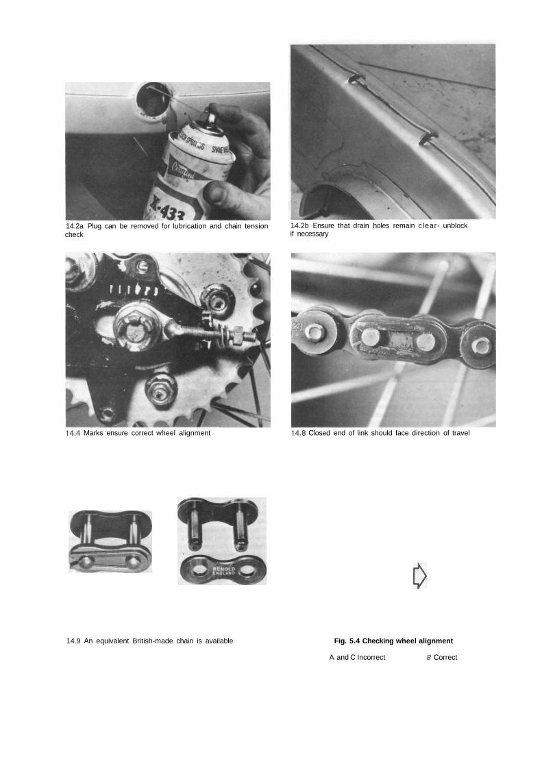
14.2a Plug can be removed for lubrication and chain tensioncheck
14.2b Ensure that drain holes remain clear- unblockif necessary
14.4 Marks ensure correct wheel alignment 14.8 Closed end of link should face direction of travel
l>
14.9 An equivalent British-made chain is available Fig. 5.4 Checking wheel alignment
A and C Incorrect B Correct
Chapter 5 Wheels, brakes and tyres 91
15 Rear wheel: replacement
1 Clean and grease the rear wheel spindle, check that thesprocket and dust cover have been refitted to the hub left-handside, and refit the brake plate assembly to the drum. Fit one ofthe chain adjusting drawbolts under the spindle head.2 Note that while the spindle can physically be fitted eitherway round it is usually shown in the manufacturer's literature asbeing fitted from right to left and is generally found to be fittedthis way on new machines. However, if it is fitted from left toright, so that the nut is on the right-hand side, the task of wheelremoval is greatly eased by the fact that it is no longernecessary to remove the exhaust system.3 Fit the wheel to the swinging arm fork ends and refit thespindle, ensuring that both spacers and drawbolts are correctlypositioned. Refit and lightly tighten the spindle nut. Connect thebrake torque arm to the brake plate, and the brake rod to theactuating lever, then adjust the chain as described in Section14.4 Applying the rear brake firmly, tighten the spindle nut to atorque setting of 4.0 - 5.0 kgf m (29 - 36 Ibf ft) and secure itby fitting a new split pin with its ends bent over correctly.Tighten securely the torque arm retaining nut and refit its springpin, then adjust the rear brake and stoplamp switch asdescribed in Section 13.5 Lubricate the chain and refit the enclosure, ensuring that allmating surfaces are correctly engaged before the mountingbolts are secured.
16 Tyres: removal and replacement
1 At some time or other the need will arise to remove andreplace the tyres, either as the result of a puncture or because areplacement is required to offset wear. To-the inexperienced,tyre changing represents a formidable task yet if a few simple•rules are observed and the technique learned, the whole opera-tion is surprisingly simple.2 To remove the tyre from either wheel, first detach the wheelfrom the machine by following the procedure in Chapter 5.3 or5.9, depending on whether the front or the rear wheel isinvolved. Deflate the tyre by removing the valve insert and whenit is fully deflated, push the bead of the tyre away from thewheel rim on both sides so that the bead enters the centre weltof the rim. Remove the locking cap and push the tyre valve intothe tyre itself.3 Insert a tyre lever close to the valve and lever the edge ofthe tyre over the outside of the wheel rim. Very little forceshould be necessary; if resistance is encountered it is probablydue to the fact that the tyre beads have not entered the well ofthe wheel rim all the way round the tyre.4 Once the tyre has been edged over the wheel rim, it is easyto work around the wheel rim so that the tyre is completely freeon one side. At this stage, the inner tube can be removed.5 Working from the other side of the wheel, ease the otheredge of the tyre over the outside of the wheel rim that isfurthest away. Continue to work around the rim until the tyre isfree completely from the rim.6 If a puncture has necessitated tyre removal, reinflate theinner tube and immerse it in a bowl of water to trace the sourceof the leak. Mark its position and deflate the tube. Dry the tube
and clean the area around the puncture with a petrol soakedrag. When the surface has dried, apply the rubber solution andallow this to dry before removing the backing from the patchand applying the patch to the surface.7 It is best to use a patch of self vulcanising type, which willform a very permanent repair. Note that it may be necessary toremove a protective covering from the top surface of the patch,after it has sealed in position. Inner tubes made from syntheticrubber may require a special type of patch and adhesive, if asatisfactory bond is to be achieved.8 Before replacing the tyre, check the inside to make sure theagent that caused the pun.cture is not trapped. Check also theoutside of the tyre — particularly the tread area, to make surenothing is trapped that may cause a further puncture.9 If the inner tube has been patched on a number of pastoccasions, or if there is a tear or large hole, it is preferable todiscard it and fit a replacement. Sudden deflation may cause anaccident, particularly if it occurs with the front wheel.10 To replace the tyre, inflate the inner tube sufficiently for it toassume a circular shape but only just. Then put it into the tyreso that it is enclosed completely. Lay the tyre on the wheel at anangle and insert the valve through the rim tape and the hole inthe wheel rim. Attach the locking cap on the first few threads,sufficient to hold the valve captive in its correct location.1 1 Starting at the point furthest from the valve, push the tyrebead over the edge of the wheel rim until it is located in thecentral well. Continue to work around the tyre in this fashionuntil the whole of one side of the tyre is on the rim. It may benecessary to use a tyre lever during the final stages.12 Make sure there is no pull on the tyre valve and again com-mencing with the area furthest from the valve, ease the otherbead of the tyre over the edge of the rim. Finish with the areaclose to the valve, pushing the valve up into the tyre until thelocking cap touches the rim. This will ensure the inner tube isnot trapped when the last section of the bead is edged over therim with a tyre lever.13 Check that the inner tube is not trapped at any point.Reinflate the inner tube and check that the tyre is seatingcorrectly around the wheel rim. There should be a thin ribmoulded around the wall of the tyre on both sides, which shouldbe equidistant from the wheel rim at all points. If the tyre isunevenly located on the rim, try bouncing the wheel when thetyre is at the recommended pressure. It is probable that one ofthe beads has not pulled clear of the centre well.14 Always run the tyres at the recommended pressures andnever under or over-inflate. The correct pressures for solo useare given in the Specifications Section of this Chapter.15 Tyre replacement is aided by dusting the side walls,particularly in the vicinity of the beads, with a liberal coating ofFrench chalk. Washing up liquid can also be used to good effect,but this has the disadvantage of causing the inner surfaces ofthe wheel rim to rust.16 Never replace the inner tube and tyre without the rim tapein position. If this precaution is overlooked there is good chanceof the ends of the spoke nipples chafing the inner tube andcausing a crop of punctures.17 Never fit a tyre that has a damaged tread or side walls.Apart from the legal aspects, there is a very great risk of a blow-out, which can have serious consequences on any two-wheelvehicles.18 Tyre valves rarely give trouble, but it is always advisable tocheck whether the valve itself is leaking before removing thetyre. Do not forget to fit the dust cap, which forms an effectivesecond seal.

1
92 Chapter 5 Wheels, brakes and tyres
17 Fault diagnosis: wheels, brakes and tyres
Symptom Cause Remedy
Ineffective brakes
Handlebars oscillate at low speeds
Machine lacks power and pooracceleration
Brakes grab when applied gently
Brake pull-off spongy
Harsh transmission
Worn brake lining or padsForeign bodies on brake linings surfaceIncorrect engagement of brake armserrationWorn brake cam
Renew.Clean.
Reset correctly.Renew.
Buckle orflat in wheel rim, most likely frontwheel
Tyre not straight on rim
Brakes binding
Ends of brake shoes not chamferedElliptical brake drumBadly worn pads
Brake cam binding in housingWeak brake shoe springs
Worn or badly adjusted final drive chainHooked or badly worn sprocketsLoose rear sprocketWorn damper rubbers
Check rim alignment by spinning wheel.Correct by retensioning spokes or buildingon new rim.Check tyre alignment.
Warm brake drum provides best evidence.Re-adjust brakes.
Chamfer with file.Lightly skim on lathe.Renew.
Free and grease.Renew if springs have not become displaced
Adjust or renew.Renew as a pair.Check bolts.Renew rubber inserts.
Chapter 6 Electrical systemRefer to Chapter 7 for information relating to the 1985 on Brazilian models
Contents
General description 1Checking the electrical system : general 2Charging system : checking the output 3Rectifier : checking for malfunctions 4Battery : charging procedure and maintenance 5Headlamp : replacing bulbs and adjusting beam height 6Tail and stop lamp : replacing bulbs 7Rear brake stop lamp switch : adjusting 8Front brake stop lamp switch : location and replacement 9Instrument illumination and warning lamps replacing bulbs 10
Flashing indicator lamps 11Flasher unit : location and replacement 12Headlamp dip switch 13Horn push and horn adjustment 14Fuse : location and replacement 15Ignition switch: location and replacement 16Resistor: function and testing 17Wiring: layout and examination 18Fault diagnosis 19
Specifications
Electrical systemVoltage 6Earth connection Negative (—)Generator output 81W a> 6000 rpmFuse rating 10A
BatteryMake and type Yuasa 6N6-3BCapacity 6Ah
BulbsHeadlamp 6V, 25/25WPilot lamp
Early CG125 models N/AppLater CG125 models, CG125 K1, B 6V, 4WCG125-C, E 6V, 3W
Speedometer illuminationCG125, CG125 K1, B 6V, 1.7WCG125-C, E 6V, 3.4W
Flashing indicator warning 6V, 1.7WNeutral indicator
CG125, CG125 K1, B 6V, 3WCG125-C, E 6V, 3.4W
Flashing indicator lamps 6V, 18WStop/tail lamp 6V, 21/5WNote: Some CGI25-C and E models may use 6V, 17/5.3W stop/tail lamp bulbs - check bulbholder marking for correctbulb rating
1 General description
The electrical system is powered by a generator mountedon the left-hand end of the crankshaft. It is normally of ND(Nippon Denso) manufacture, though occasionally a Hitachi unitis used. The latter can be identified by its having threegenerating coils, as opposed to the ND unit which has two. Caremust be taken to obtain parts which are designed for each typeof generator, but apart from this, they can be regarded asidentical in function.
Alternating current produced by the generator is passedthrough a silicon rectifier which converts it to direct current,which in turn is fed to the battery. Output from the generator ismatched to differing loadings on the system in accordance withthe various switch positions.
2 Checking the electrical system: general
Many of the test procedures applicable to motorcycleelectrical systems require the use of test equipment of the mul-timeter type. Although the tests themselves are quite straight-forward, there is a real danger, particularly on alternatorsystems, of damaging certain components if wrong connectionsare made. It is recommended, therefore, that no attempt bemade to investigate faults in the charging system, unless theowner is reasonably experienced in the field. A qualified HondaService Agent will have in his possession the necessarydiagnostic equipment to effect an economical repair.
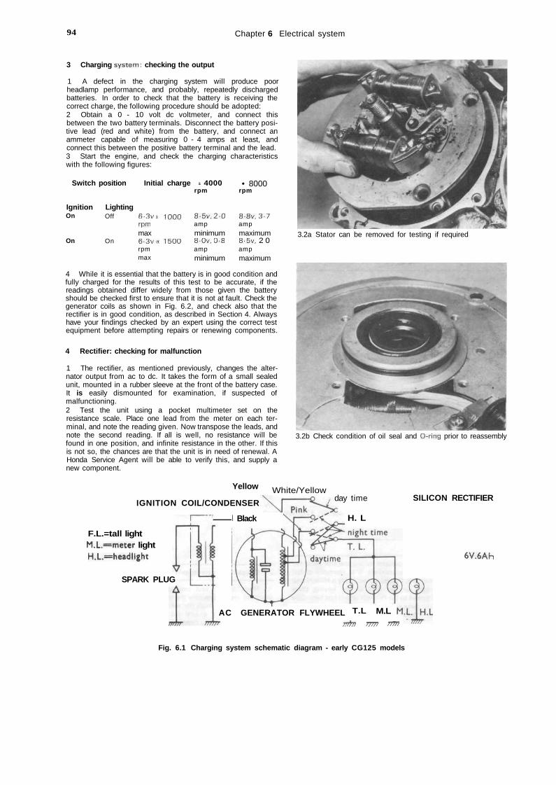
94 Chapter 6 Electrical system
3 Charging system: checking the output
1 A defect in the charging system will produce poorheadlamp performance, and probably, repeatedly dischargedbatteries. In order to check that the battery is receiving thecorrect charge, the following procedure should be adopted:2 Obtain a 0 - 10 volt dc voltmeter, and connect thisbetween the two battery terminals. Disconnect the battery posi-tive lead (red and white) from the battery, and connect anammeter capable of measuring 0 - 4 amps at least, andconnect this between the positive battery terminal and the lead.3 Start the engine, and check the charging characteristicswith the following figures:
Switch
IgnitionOn
On
position
LightingOff
On
Initial charge
6-3v arpmmax6-3v«rpmmax
1000
1500
a 4000rpm
8-5v,20ampminimum8-0v, 0-8ampminimum
• 8000rpm
8-8v, 3-7ampmaximum8-5v, 2 0ampmaximum
4 While it is essential that the battery is in good condition andfully charged for the results of this test to be accurate, if thereadings obtained differ widely from those given the batteryshould be checked first to ensure that it is not at fault. Check thegenerator coils as shown in Fig. 6.2, and check also that therectifier is in good condition, as described in Section 4. Alwayshave your findings checked by an expert using the correct testequipment before attempting repairs or renewing components.
4 Rectifier: checking for malfunction
1 The rectifier, as mentioned previously, changes the alter-nator output from ac to dc. It takes the form of a small sealedunit, mounted in a rubber sleeve at the front of the battery case.It is easily dismounted for examination, if suspected ofmalfunctioning.2 Test the unit using a pocket multimeter set on theresistance scale. Place one lead from the meter on each ter-minal, and note the reading given. Now transpose the leads, andnote the second reading. If all is well, no resistance will befound in one position, and infinite resistance in the other. If thisis not so, the chances are that the unit is in need of renewal. AHonda Service Agent will be able to verify this, and supply anew component.
3.2a Stator can be removed for testing if required
3.2b Check condition of oil seal and O-ring prior to reassembly
Yellow
IGNITION COIL/CONDENSER
1 Black
White/Yellow
F.L.=tall lightM.L=meter lightH.L.=headlight
SPARK PLUG
day time
H. L
SILICON RECTIFIER
AC GENERATOR FLYWHEEL T.L
6V.6AH
M.L
!!))» !!/>/ !>/!!
Fig. 6.1 Charging system schematic diagram - early CG125 models
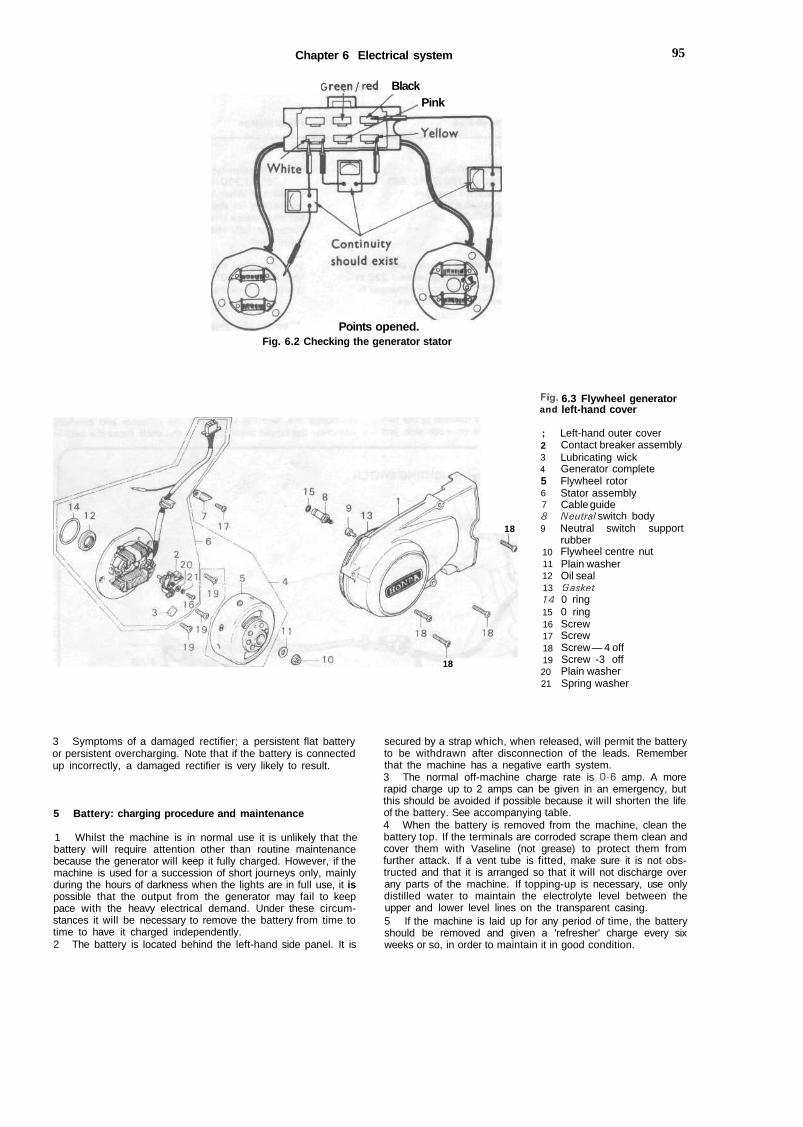
Chapter 6 Electrical system 95
Green/red BlackPink
Points opened.Fig. 6.2 Checking the generator stator
18
18
Fig.and
;23456789
101112131415161718192021
6.3 Flywheel generatorleft-hand cover
Left-hand outer coverContact breaker assemblyLubricating wickGenerator completeFlywheel rotorStator assemblyCable guideNeutral switch bodyNeutral switch supportrubberFlywheel centre nutPlain washerOil sealGasket0 ring0 ringScrewScrewScrew — 4 offScrew -3 offPlain washerSpring washer
3 Symptoms of a damaged rectifier; a persistent flat batteryor persistent overcharging. Note that if the battery is connectedup incorrectly, a damaged rectifier is very likely to result.
5 Battery: charging procedure and maintenance
1 Whilst the machine is in normal use it is unlikely that thebattery will require attention other than routine maintenancebecause the generator will keep it fully charged. However, if themachine is used for a succession of short journeys only, mainlyduring the hours of darkness when the lights are in full use, it ispossible that the output from the generator may fail to keeppace with the heavy electrical demand. Under these circum-stances it will be necessary to remove the battery from time totime to have it charged independently.2 The battery is located behind the left-hand side panel. It is
secured by a strap which, when released, will permit the batteryto be withdrawn after disconnection of the leads. Rememberthat the machine has a negative earth system.3 The normal off-machine charge rate is 0-6 amp. A morerapid charge up to 2 amps can be given in an emergency, butthis should be avoided if possible because it will shorten the lifeof the battery. See accompanying table.4 When the battery is removed from the machine, clean thebattery top. If the terminals are corroded scrape them clean andcover them with Vaseline (not grease) to protect them fromfurther attack. If a vent tube is fitted, make sure it is not obs-tructed and that it is arranged so that it will not discharge overany parts of the machine. If topping-up is necessary, use onlydistilled water to maintain the electrolyte level between theupper and lower level lines on the transparent casing.5 If the machine is laid up for any period of time, the batteryshould be removed and given a 'refresher' charge every sixweeks or so, in order to maintain it in good condition.
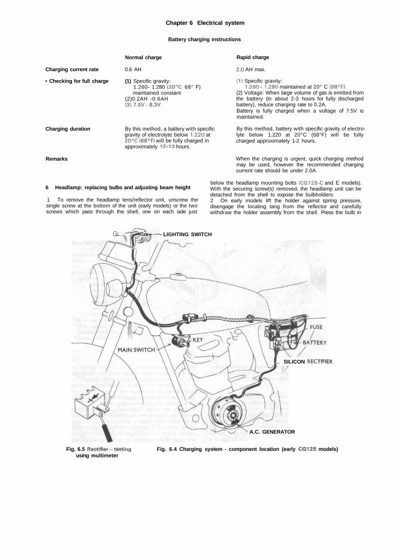
Chapter 6 Electrical system
Battery charging instructions
Normal charge Rapid charge
Charging current rate
• Checking for full charge
Charging duration
Remarks
0.6 AH
(1) Specific gravity:1.260- 1.280 (20°C: 68° F)maintained constant
(2)0.2AH -0.6AH(3) 7.5V-8.3V
By this method, a battery with specificgravity of electrolyte below 1.220 at20°C (68°F) will be fully charged inapproximately 12-13 hours.
2.0 AH max.
(1) Specific gravity:1.260 - 1.280 maintained at 20° C (68°F)
(2) Voltage: When large volume of gas is emitted fromthe battery (in about 2-3 hours for fully dischargedbattery), reduce charging rate to 0.2A.Battery is fully charged when a voltage of 7.5V ismaintained.
By this method, battery with specific gravity of electro-lyte below 1.220 at 20°C (68°F) will be fullycharged approximately 1-2 hours.
6 Headlamp: replacing bulbs and adjusting beam height
1 To remove the headlamp lens/reflector unit, unscrew thesingle screw at the bottom of the unit (early models) or the twoscrews which pass through the shell, one on each side just
When the charging is urgent, quick charging methodmay be used, however the recommended chargingcurrent rate should be under 2.0A.
below the headlamp mounting bolts (CG125-C and E models).With the securing screw(s) removed, the headlamp unit can bedetached from the shell to expose the bulbholders.2 On early models lift the holder against spring pressure,disengage the locating tang from the reflector and carefullywithdraw the holder assembly from the shell. Press the bulb in
Q L , - LIGHTING SWITCH
SILICON RECTIFIER
Fig. 6.5 Rectifier-testingusing multimeter
A.C. GENERATOR
Fig. 6.4 Charging system - component location (early CG125 models)
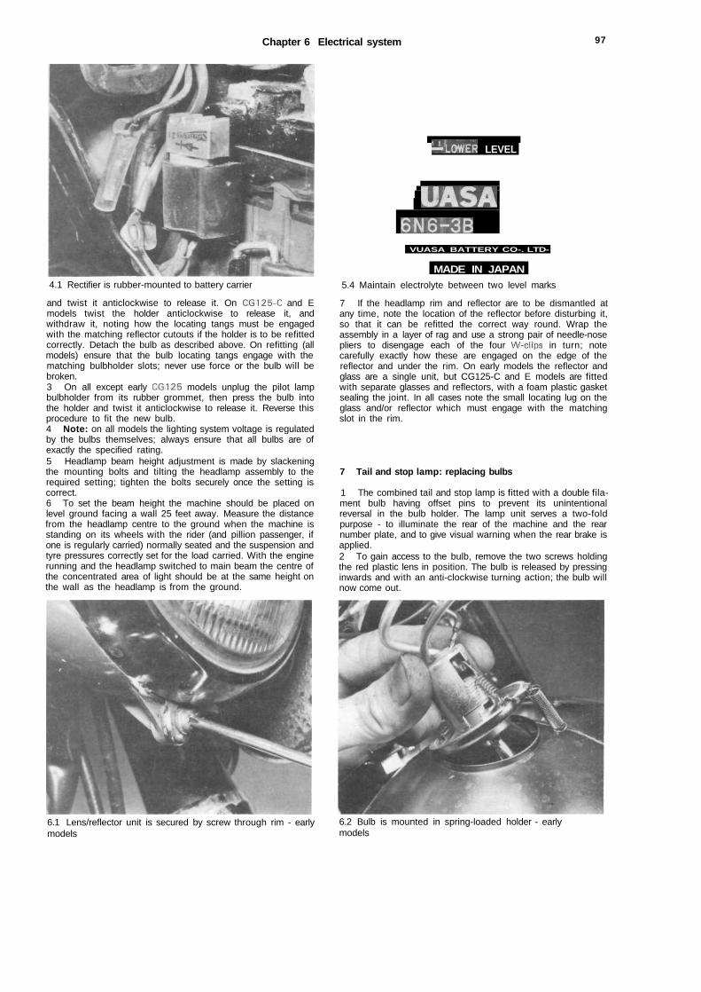
Chapter 6 Electrical system 97
4.1 Rectifier is rubber-mounted to battery carrier
and twist it anticlockwise to release it. On CG125-C and Emodels twist the holder anticlockwise to release it, andwithdraw it, noting how the locating tangs must be engagedwith the matching reflector cutouts if the holder is to be refittedcorrectly. Detach the bulb as described above. On refitting (allmodels) ensure that the bulb locating tangs engage with thematching bulbholder slots; never use force or the bulb will bebroken.3 On all except early CG125 models unplug the pilot lampbulbholder from its rubber grommet, then press the bulb intothe holder and twist it anticlockwise to release it. Reverse thisprocedure to fit the new bulb.4 Note: on all models the lighting system voltage is regulatedby the bulbs themselves; always ensure that all bulbs are ofexactly the specified rating.5 Headlamp beam height adjustment is made by slackeningthe mounting bolts and tilting the headlamp assembly to therequired setting; tighten the bolts securely once the setting iscorrect.6 To set the beam height the machine should be placed onlevel ground facing a wall 25 feet away. Measure the distancefrom the headlamp centre to the ground when the machine isstanding on its wheels with the rider (and pillion passenger, ifone is regularly carried) normally seated and the suspension andtyre pressures correctly set for the load carried. With the enginerunning and the headlamp switched to main beam the centre ofthe concentrated area of light should be at the same height onthe wall as the headlamp is from the ground.
—loWER LEVEL
UASA6N6-3B
VUASA BATTERY CO-. LTD-
MADE IN JAPAN5.4 Maintain electrolyte between two level marks
7 If the headlamp rim and reflector are to be dismantled atany time, note the location of the reflector before disturbing it,so that it can be refitted the correct way round. Wrap theassembly in a layer of rag and use a strong pair of needle-nosepliers to disengage each of the four W-clips in turn; notecarefully exactly how these are engaged on the edge of thereflector and under the rim. On early models the reflector andglass are a single unit, but CG125-C and E models are fittedwith separate glasses and reflectors, with a foam plastic gasketsealing the joint. In all cases note the small locating lug on theglass and/or reflector which must engage with the matchingslot in the rim.
7 Tail and stop lamp: replacing bulbs
1 The combined tail and stop lamp is fitted with a double fila-ment bulb having offset pins to prevent its unintentionalreversal in the bulb holder. The lamp unit serves a two-foldpurpose - to illuminate the rear of the machine and the rearnumber plate, and to give visual warning when the rear brake isapplied.2 To gain access to the bulb, remove the two screws holdingthe red plastic lens in position. The bulb is released by pressinginwards and with an anti-clockwise turning action; the bulb willnow come out.
6.1 Lens/reflector unit is secured by screw through rim - earlymodels
6.2 Bulb is mounted in spring-loaded holder - earlymodels

98
11
Fig. 6.6 Headlamp unit - CG125. CG125 K1 and B models
1 Rim2 W-clip - 4 off3 Screw4 Washer5 Reflector
6 Headlamp bulb7 Bulbholder8 Pilot lamp bulb*9 Grommet10 Shell
11 Bolt -2 off12 Washer - 2 off13 Nut - 2 off
*not fitted to early CGI25 models
Fig. 6.7 Headlamp unit - CG125-C and E models
/23456
RimGlassGasketW-clip - 4ReflectorHeadlamp
off
bulb
7891011
Bulb holderBulbholderGrommetPilot lamp bulbShell
12 Bolt - 2 off13 Screw - 2 off14 Spring washer - 2 off15 Spacer - 2 off16 Nut - 2 off
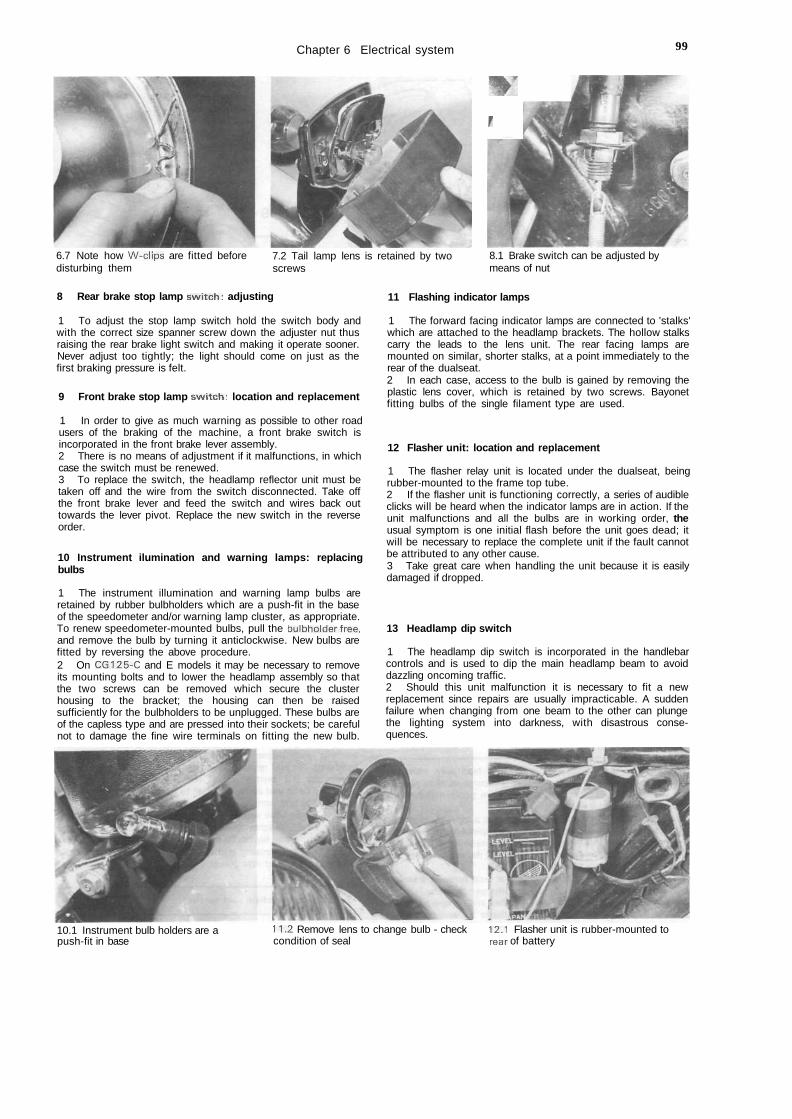
Chapter 6 Electrical system 99
wr
6.7 Note how W-clips are fitted beforedisturbing them
7.2 Tail lamp lens is retained by twoscrews
8.1 Brake switch can be adjusted bymeans of nut
8 Rear brake stop lamp switch: adjusting
1 To adjust the stop lamp switch hold the switch body andwith the correct size spanner screw down the adjuster nut thusraising the rear brake light switch and making it operate sooner.Never adjust too tightly; the light should come on just as thefirst braking pressure is felt.
9 Front brake stop lamp switch: location and replacement
1 In order to give as much warning as possible to other roadusers of the braking of the machine, a front brake switch isincorporated in the front brake lever assembly.2 There is no means of adjustment if it malfunctions, in whichcase the switch must be renewed.3 To replace the switch, the headlamp reflector unit must betaken off and the wire from the switch disconnected. Take offthe front brake lever and feed the switch and wires back outtowards the lever pivot. Replace the new switch in the reverseorder.
10 Instrument ilumination and warning lamps: replacingbulbs
1 The instrument illumination and warning lamp bulbs areretained by rubber bulbholders which are a push-fit in the baseof the speedometer and/or warning lamp cluster, as appropriate.To renew speedometer-mounted bulbs, pull the bulbholderfree,and remove the bulb by turning it anticlockwise. New bulbs arefitted by reversing the above procedure.2 On CG125-C and E models it may be necessary to removeits mounting bolts and to lower the headlamp assembly so thatthe two screws can be removed which secure the clusterhousing to the bracket; the housing can then be raisedsufficiently for the bulbholders to be unplugged. These bulbs areof the capless type and are pressed into their sockets; be carefulnot to damage the fine wire terminals on fitting the new bulb.
11 Flashing indicator lamps
1 The forward facing indicator lamps are connected to 'stalks'which are attached to the headlamp brackets. The hollow stalkscarry the leads to the lens unit. The rear facing lamps aremounted on similar, shorter stalks, at a point immediately to therear of the dualseat.2 In each case, access to the bulb is gained by removing theplastic lens cover, which is retained by two screws. Bayonetfitting bulbs of the single filament type are used.
12 Flasher unit: location and replacement
1 The flasher relay unit is located under the dualseat, beingrubber-mounted to the frame top tube.2 If the flasher unit is functioning correctly, a series of audibleclicks will be heard when the indicator lamps are in action. If theunit malfunctions and all the bulbs are in working order, theusual symptom is one initial flash before the unit goes dead; itwill be necessary to replace the complete unit if the fault cannotbe attributed to any other cause.3 Take great care when handling the unit because it is easilydamaged if dropped.
13 Headlamp dip switch
1 The headlamp dip switch is incorporated in the handlebarcontrols and is used to dip the main headlamp beam to avoiddazzling oncoming traffic.2 Should this unit malfunction it is necessary to fit a newreplacement since repairs are usually impracticable. A suddenfailure when changing from one beam to the other can plungethe lighting system into darkness, with disastrous conse-quences.
10.1 Instrument bulb holders are apush-fit in base
11.2 Remove lens to change bulb - checkcondition of seal
12.1 Flasher unit is rubber-mounted torear of battery
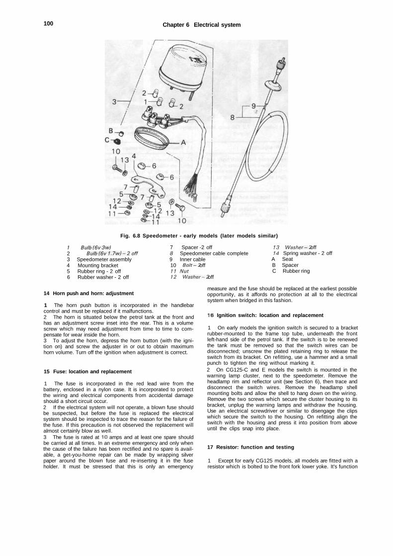
100 Chapter 6 Electrical system
Fig. 6.8 Speedometer - early models (later models similar)
/ Bulb(6v3w)2 Bulb(6v1.7w)-2off3 Speedometer assembly4 Mounting bracket5 Rubber ring - 2 off6 Rubber washer - 2 off
7 Spacer -2 off8 Speedometer cable complete9 Inner cable10 Bolt-2 off11 Nut12 Washer-2 off
13 Washer-2 off14 Spring washer - 2 offA SeatB SpacerC Rubber ring
14 Horn push and horn: adjustment
1 The horn push button is incorporated in the handlebarcontrol and must be replaced if it malfunctions.2 The horn is situated below the petrol tank at the front andhas an adjustment screw inset into the rear. This is a volumescrew which may need adjustment from time to time to com-pensate for wear inside the horn.3 To adjust the horn, depress the horn button (with the igni-tion on) and screw the adjuster in or out to obtain maximumhorn volume. Turn off the ignition when adjustment is correct.
15 Fuse: location and replacement
1 The fuse is incorporated in the red lead wire from thebattery, enclosed in a nylon case. It is incorporated to protectthe wiring and electrical components from accidental damageshould a short circuit occur.2 If the electrical system will not operate, a blown fuse shouldbe suspected, but before the fuse is replaced the electricalsystem should be inspected to trace the reason for the failure ofthe fuse. If this precaution is not observed the replacement willalmost certainly blow as well.3 The fuse is rated at 10 amps and at least one spare shouldbe carried at all times. In an extreme emergency and only whenthe cause of the failure has been rectified and no spare is avail-able, a get-you-home repair can be made by wrapping silverpaper around the blown fuse and re-inserting it in the fuseholder. It must be stressed that this is only an emergency
measure and the fuse should be replaced at the earliest possibleopportunity, as it affords no protection at all to the electricalsystem when bridged in this fashion.
16 Ignition switch: location and replacement
1 On early models the ignition switch is secured to a bracketrubber-mounted to the frame top tube, underneath the frontleft-hand side of the petrol tank. If the switch is to be renewedthe tank must be removed so that the switch wires can bedisconnected; unscrew the plated retaining ring to release theswitch from its bracket. On refitting, use a hammer and a smallpunch to tighten the ring without marking it.2 On CG125-C and E models the switch is mounted in thewarning lamp cluster, next to the speedometer. Remove theheadlamp rim and reflector unit (see Section 6), then trace anddisconnect the switch wires. Remove the headlamp shellmounting bolts and allow the shell to hang down on the wiring.Remove the two screws which secure the cluster housing to itsbracket, unplug the warning lamps and withdraw the housing.Use an electrical screwdriver or similar to disengage the clipswhich secure the switch to the housing. On refitting align theswitch with the housing and press it into position from aboveuntil the clips snap into place.
17 Resistor: function and testing
1 Except for early CG125 models, all models are fitted with aresistor which is bolted to the front fork lower yoke. It's function

Chapter 6 Electrical system 101
14.2 Horn is located here 15.1 Main fuse holder clips to battery case
15.2 Spare fuses should be kept in holder inside panel 17.2 Wiring is colour-coded to facilitate tracing of faults
is to drain off excess power generated when only the side lightsare in use and to convert it to heat which is dissipated by theair stream. When the main headlamp is in use, the resistor isswitched out of the circuit so that full current is available tomeet the increased electrical demand.2 If the pilot light burns out with recurring frequency but theheadlamp is unaffected, the resistor should be suspected.Because it is a sealed unit a new replacement should be fitted.For those with the necessary equipment the resistor can betested. Connect a multimeter, set to the most sensitiveresistance function, between the brown wire terminal and earth.The correct resistance for the unit fitted to CG125-C and Emodels is 2 ohms; a similar reading can be expected from theunit fitted to earlier models. If the reading obtained issignificantly different, the resistor must be considered faulty andrenewed.
18 Wiring: layout and examination
1 The cables of the wiring harness are colour-coded and willcorrespond with the accompanying wiring diagrams.2 Visual inspection will show whether any breaks or frayedouter coverings are giving rise to short circuits which will causethe main fuse to blow. Another source of trouble is the snapconnectors and spade terminals, which may make a poor con-nection if they are not pushed home fully.3 Intermittent short circuits can sometimes be traced to achafed wire passing through, or close to, a metal component,such as a frame member. Avoid tight bends in the cables orsituations where the cables can be trapped or stretched,especially in the vicinity of the handlebars or steering head.
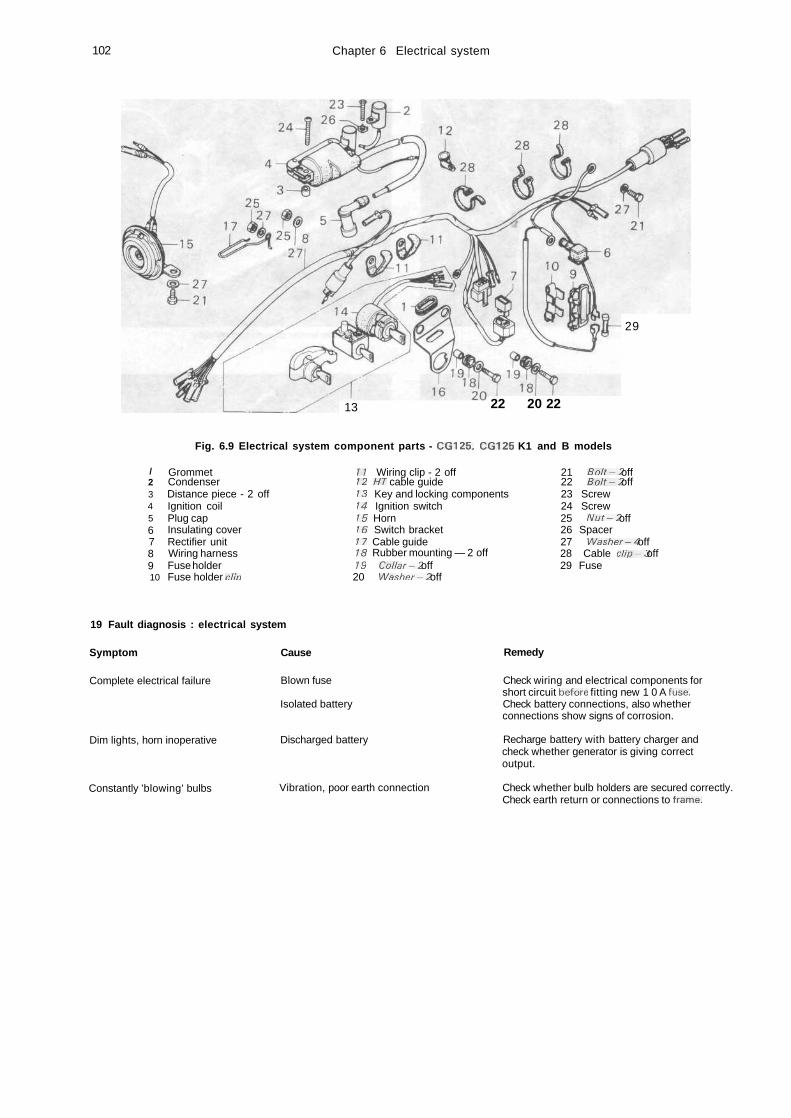
102 Chapter 6 Electrical system
29
13 22 20 22
Fig. 6.9 Electrical system component parts - CGI 25, CG125 K1 and B models
/2345678910
GrommetCondenserDistance piece - 2 offIgnition coilPlug capInsulating coverRectifier unitWiring harnessFuse holderFuse holder clio
11 Wiring clip - 2 off12 HT cable guide13 Key and locking components14 Ignition switch15 Horn16 Switch bracket17 Cable guide18 Rubber mounting — 2 off19 Collar-2 off20 Washer-2 off
21 Bolt-2 off22 Bolt-2 off23 Screw24 Screw25 Nut-2 off26 Spacer27 Washer-4 off28 Cable clip-3 off29 Fuse
19 Fault diagnosis : electrical system
Symptom Cause Remedy
Complete electrical failure
Dim lights, horn inoperative
Constantly 'blowing' bulbs
Blown fuse
Isolated battery
Discharged battery
Vibration, poor earth connection
Check wiring and electrical components forshort circuit before fitting new 1 0 A fuse.Check battery connections, also whetherconnections show signs of corrosion.
Recharge battery with battery charger andcheck whether generator is giving correctoutput.
Check whether bulb holders are secured correctly.Check earth return or connections to frame.
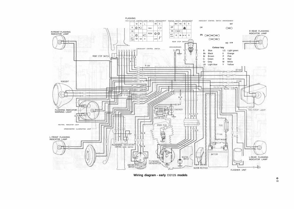
R.FRONT FLASHINGINDICATOR LAMP
FLASHINGI N D I C A T O R CONTROL-HORN SWITCH ARRANGEMENT IGNITION SWITCH ARRANGEMENT
R
(N)
L
wifecoior
W
o
oGr
R
-o
LB
L
o0
FREE
PUSH
HO
oLG/R
E
o-o
//
OFF
ON
wirecolor
BAT
OR
HO
OBk
IG
a
Bk.'W
E
G
HEADLIGHT CONTROL SWITCH ARRANGEMENT
L FRONT FLASHINGINDICATOR LAMP
REAR STOP SWITCH
GROUND(fRAME)
OFF
(N) oooooo-o
o-o
w/y
BAT
R'W
R REAR FLASHINGINDICATOR LAMP
Colour keyB Blue LG Light greenBk Black 0 OrangeBr Brown P PinkG Green R RedGr Grey W WhiteLB Light blue Y Yellow
HEADLIGHT CONTROL SWITCH
#3S£=o±-LG/R-CZIO-LG/R
FLASHING INDICATORWARNING LIGHT
NEUTRAL INDICATOR LIGHT
SPEEDOMETER ILLUMINATING LIGHT
FLASHING INDICATOR T 8 GCONTROL HORN SWITCH
L.REAR FLASHINGINDICATOR LAMP
FLASHER UNIT
Wiring diagram - early CG125 modelso00
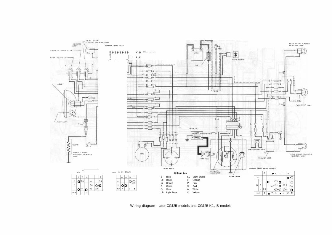
FRONT RHANDIDICATOR LAMP
SPEEDOME-£<! . L L U M M T M G JGn1
HEADLIGHT OIMMER SWITCH
FRONT L HANDFLASHING INDICATORLAMP
f 9 9 9 9 9 9 9 9! 9
f ! B C»B- * - '
1 • i „!„. i
-WONT STOP LIGHT SWITCH
R
s
COL DC
TOR
I
o
o
MO*
•
•o
—LB
-
o0
FSEE
PUSH
COL Off
oL G / B
E
Oo
IGNITION Sw
OFF
ON
CCIOK
TCH
BA'
oR
OHTWUIT*
HO
o
16
o
8- *
I
fO
s
IGNITICM SWITCH
Colour key
B Blue LG Light greenBk Black 0 OrangeBr Brown P PinkG Green R RedGr Grey W WhiteLB Light blue Y Yellow
REAR RHAND FLASHINGINDICATOR LAMP
TAIL/STOP LAMP
REAR L.HAND FLASHINGINDICATOR LAMP
HEADLIGHT OlMMEfi SWITCH CONTINUITY
NEUTRAL SWITCHOFF
ON
L
P
-
COLOR
x
OB
o
»
»
aa.
TL
OOo
Br
Cl
oo-o•
CH
op
C3
o—1
—
m
•O
oooR/w
Wiring diagram - later CG125 models and CG125 K1, B models
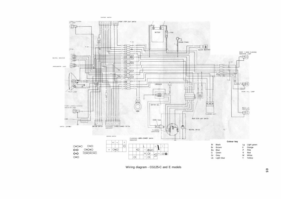
LIGHTING SWITCH
NEUTRAL INDICATOR
SPEEDOMETER LIGHT
SWITCH CONTINUIT
IGNITION SWITCH
o-ooo-oo-ooo
ooaoo
"o-o-o-oON
B A '
O
».
fO
E
O
FLASHING "HORN-DIMMER SWITCHINDICATOR
REAR R HAND FLASHINGINDICATOR LAMP
STOP /TAIL LAMP
o
•o\
H,
IN)
L .
ooo
ou
r°\FREE
PUSH
-
o
•
o
Colour key
Bl Black Lg Light greenBr Brown 0 OrangeBu Blue P PinkG Green R RedGr Grey W WhiteLb Light blue Y Yellow
Wiring diagram - CG125-C and E modelsO01
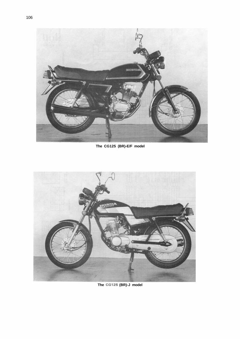
106
The CG125 (BR)-E/F model
The CG125 (BR)-J model
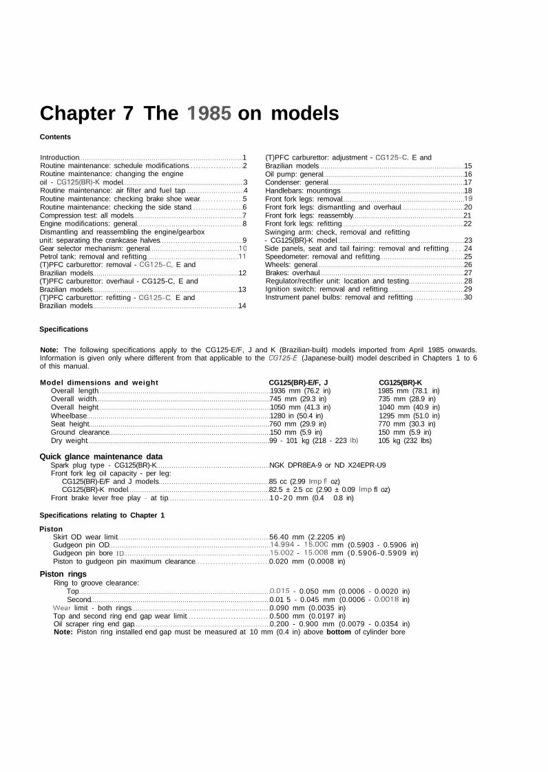
Chapter 7 The 1985 on modelsContents
Introduction 1Routine maintenance: schedule modifications 2Routine maintenance: changing the engineoil - CG125(BR)-K model 3Routine maintenance: air filter and fuel tap 4Routine maintenance: checking brake shoe wear 5Routine maintenance: checking the side stand 6Compression test: all models 7Engine modifications: general 8Dismantling and reassembling the engine/gearboxunit: separating the crankcase halves 9Gear selector mechanism: general 10Petrol tank: removal and refitting 11(T)PFC carburettor: removal - CG125-C, E andBrazilian models 12(T)PFC carburettor: overhaul - CG125-C, E andBrazilian models 13(T)PFC carburettor: refitting - CG125-C, E andBrazilian models 14
(T)PFC carburettor: adjustment - CG125-C, E andBrazilian models 15Oil pump: general 16Condenser: general 17Handlebars: mountings 18Front fork legs: removal 19Front fork legs: dismantling and overhaul 20Front fork legs: reassembly 21Front fork legs: refitting 22Swinging arm: check, removal and refitting- CG125(BR)-K model 23Side panels, seat and tail fairing: removal and refitting 24Speedometer: removal and refitting 25Wheels: general 26Brakes: overhaul 27Regulator/rectifier unit: location and testing 28Ignition switch: removal and refitting 29Instrument panel bulbs: removal and refitting 30
Specifications
Note: The following specifications apply to the CG125-E/F, J and K (Brazilian-built) models imported from April 1985 onwards.Information is given only where different from that applicable to the CG125-E (Japanese-built) model described in Chapters 1 to 6of this manual.
Model dimensions and weight CG125(BR)-E/F, J CG125(BR)-KOverall length 1936 mm (76.2 in) 1985 mm (78.1 in)Overall width 745 mm (29.3 in) 735 mm (28.9 in)Overall height 1050 mm (41.3 in) 1040 mm (40.9 in)Wheelbase 1280 in (50.4 in) 1295 mm (51.0 in)Seat height 760 mm (29.9 in) 770 mm (30.3 in)Ground clearance 150 mm (5.9 in) 150 mm (5.9 in)Dry weight 99 - 101 kg (218 - 223 Ib) 105 kg (232 lbs)
Quick glance maintenance dataSpark plug type - CG125(BR)-K NGK DPR8EA-9 or ND X24EPR-U9Front fork leg oil capacity - per leg:
CG125(BR)-E/F and J models 85 cc (2.99 Imp fl oz)CG125(BR)-K model 82.5 ± 2.5 cc (2.90 ± 0.09 Imp fl oz)
Front brake lever free play - at tip 1 0 - 2 0 mm (0.4 - 0.8 in)
Specifications relating to Chapter 1
PistonSkirt OD wear limit 56.40 mm (2.2205 in)Gudgeon pin OD 14.994 - 15.000 mm (0.5903 - 0.5906 in)Gudgeon pin bore ID 15.002 - 15.008 mm (0.5906-0.5909 in)Piston to gudgeon pin maximum clearance 0.020 mm (0.0008 in)
Piston ringsRing to groove clearance:
Top 0.015 - 0.050 mm (0.0006 - 0.0020 in)Second 0.01 5 - 0.045 mm (0.0006 - 0.0018 in)
Wear limit - both rings 0.090 mm (0.0035 in)Top and second ring end gap wear limit 0.500 mm (0.0197 in)Oil scraper ring end gap 0.200 - 0.900 mm (0.0079 - 0.0354 in)Note: Piston ring installed end gap must be measured at 10 mm (0.4 in) above bottom of cylinder bore
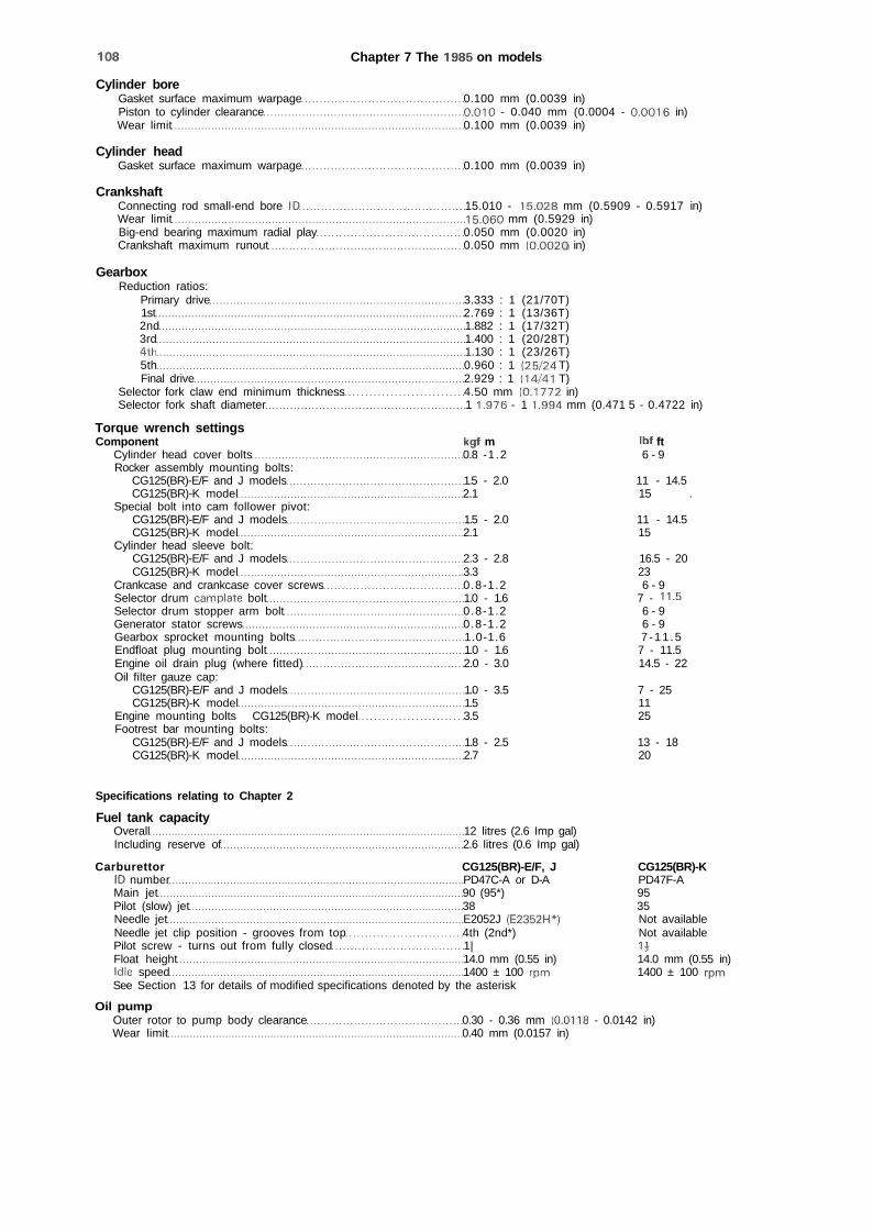
108 Chapter 7 The 1985 on models
Cylinder boreGasket surface maximum warpage 0.100 mm (0.0039 in)Piston to cylinder clearance 0.010 - 0.040 mm (0.0004 - 0.0016 in)Wear limit 0.100 mm (0.0039 in)
Cylinder headGasket surface maximum warpage 0.100 mm (0.0039 in)
CrankshaftConnecting rod small-end bore ID 15.010 - 15.028 mm (0.5909 - 0.5917 in)Wear limit 15.060 mm (0.5929 in)Big-end bearing maximum radial play 0.050 mm (0.0020 in)Crankshaft maximum runout 0.050 mm (0.002O in)
GearboxReduction ratios:
Primary drive 3.333 : 1 (21/70T)1st 2.769 : 1 (13/36T)2nd 1.882 : 1 (17/32T)3rd 1.400 : 1 (20/28T)4th 1.130 : 1 (23/26T)5th 0.960 : 1 (25/24 T)Final drive 2.929 : 1 (14/41 T)
Selector fork claw end minimum thickness 4.50 mm (0.1772 in)Selector fork shaft diameter 1 1.976 - 1 1.994 mm (0.471 5 - 0.4722 in)
Torque wrench settingsComponent kgf m Ibf ft
Cylinder head cover bolts 0.8 -1.2 6 - 9Rocker assembly mounting bolts:
CG125(BR)-E/F and J models 1.5 - 2.0 11 - 14.5CG125(BR)-K model 2.1 15 .
Special bolt into cam follower pivot:CG125(BR)-E/F and J models 1.5 - 2.0 11 - 14.5CG125(BR)-K model 2.1 15
Cylinder head sleeve bolt:CG125(BR)-E/F and J models 2.3 - 2.8 16.5 - 20CG125(BR)-K model 3.3 23
Crankcase and crankcase cover screws 0.8-1.2 6 - 9Selector drum camplate bolt 1.0 - 1.6 7 - 11.5Selector drum stopper arm bolt 0.8-1.2 6 - 9Generator stator screws 0.8-1.2 6 - 9Gearbox sprocket mounting bolts 1.0-1.6 7 -11 .5Endfloat plug mounting bolt 1.0 - 1.6 7 - 11.5Engine oil drain plug (where fitted) 2.0 - 3.0 14.5 - 22Oil filter gauze cap:
CG125(BR)-E/F and J models 1.0 - 3.5 7 - 25CG125(BR)-K model 1.5 11
Engine mounting bolts CG125(BR)-K model 3.5 25Footrest bar mounting bolts:
CG125(BR)-E/F and J models 1.8 - 2.5 13 - 18CG125(BR)-K model 2.7 20
Specifications relating to Chapter 2
Fuel tank capacityOverall 12 litres (2.6 Imp gal)Including reserve of 2.6 litres (0.6 Imp gal)
Carburettor CG125(BR)-E/F, J CG125(BR)-KID number PD47C-A or D-A PD47F-AMain jet 90 (95*) 95Pilot (slow) jet 38 35Needle jet E2052J (E2352H*) Not availableNeedle jet clip position - grooves from top 4th (2nd*) Not availablePilot screw - turns out from fully closed 1| 1JFloat height 14.0 mm (0.55 in) 14.0 mm (0.55 in)Idle speed 1400 ± 100 rpm 1400 ± 100 rpmSee Section 13 for details of modified specifications denoted by the asterisk
Oil pumpOuter rotor to pump body clearance 0.30 - 0.36 mm (0.0118 - 0.0142 in)Wear limit 0.40 mm (0.0157 in)
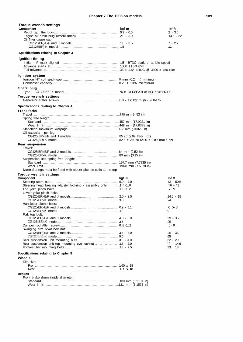
Chapter 7 The 1985 on models 109
Torque wrench settingsComponent kgf m Ibf ft
Petrol tap filter bowl 0.3 - 0.5 2 - 3.5Engine oil drain plug (where fitted) 2.0 - 3.0 14.5 - 22Oil filter gauze cap:
CG125(BR)-E/F and J models 1.0 - 3.5 7 - 25CG125(BR)-K model 1.5 11
Specifications relating to Chapter 3
Ignition timingInitial - 'F mark aligned 15° BTDC static or at idle speedAdvance starts at 1800 ±150 rpmFull advance at 35 ± 1.5° BTDC @ 3800 ± 150 rpm
Ignition systemIgnition HT coil spark gap 6 mm (0.24 in) minimumCondenser capacity 0.25 ± 10% microfarad
Spark plugType - CG125(BR)-K model NGK DPR8EA-9 or ND X24EPR-U9
Torque wrench settingsGenerator stator screws 0.8 - 1.2 kgf m (6 - 9 Ibf ft)
Specifications relating to Chapter 4Front forks
Travel 115 mm (4.53 in)Spring free length:
Standard 457 mm (17.9921 in)Wear limit 448 mm (17.6378 in)
Stanchion maximum warpage 0.2 mm (0.0079 in)Oil capacity - per leg:
CG125(BR)-E/F and J models 85 cc (2.99 Imp fl oz)CG125(BR)-K model 82.5 ± 2.5 cc (2.90 ± 0.09 Imp fl oz)
Rear suspensionTravel:
CG125(BR)-E/F and J models 64 mm (2.52 in)CG125(BR)-K model 80 mm (3.15 in)
Suspension unit spring free length:Standard 197.7 mm (7.7835 in)Wear limit 194.0 mm (7.6378 in)
Note: Springs must be fitted with closer-pitched coils at the top
Torque wrench settingsComponent kgf m Ibf ft
Steering stem nut 6.0 - 7.0 43 - 50.5Steering head bearing adjuster lockring - assembly only 1.4-1.8 10 -13Top yoke pinch bolts 1.0-1.2 7 - 9Lower yoke pinch bolts:
CG125(BR)-E/F and J models 2.0 - 2.5 14.5 - 18CG125(BR)-K model 3.3 24
Handlebar clamp bolts:CG125(BR)-E/F and J models 0.9 - 1.1 6 .5 -8CG125(BR)-K model 1.2 9
Fork top bolt:CG125(BR)-E/F and J models 4.0 - 5.0 29 - 36CG125(BR)-K model 3.5 25
Damper rod Allen screw 0.8-1.2 6 - 9Swinging arm pivot bolt nut:
CG125(BR)-E/F and J models 3.5 - 5.0 25 - 36CG125(BR)-K model 9.0 65
Rear suspension unit mounting nuts 3.0 - 4.0 22 - 29Rear suspension unit top mounting eye locknut 1.5 - 2.0 11 - 14.5Footrest bar mounting bolts 1.8 - 2.5 13 - 18
Specifications relating to Chapter 5Wheels
Rim size:Front 1.60 x 18Rear 1.85 x 18
BrakesFront brake drum inside diameter:
Standard 130 mm (5.1181 in)Wear limit 131 mm (5.1575 in)
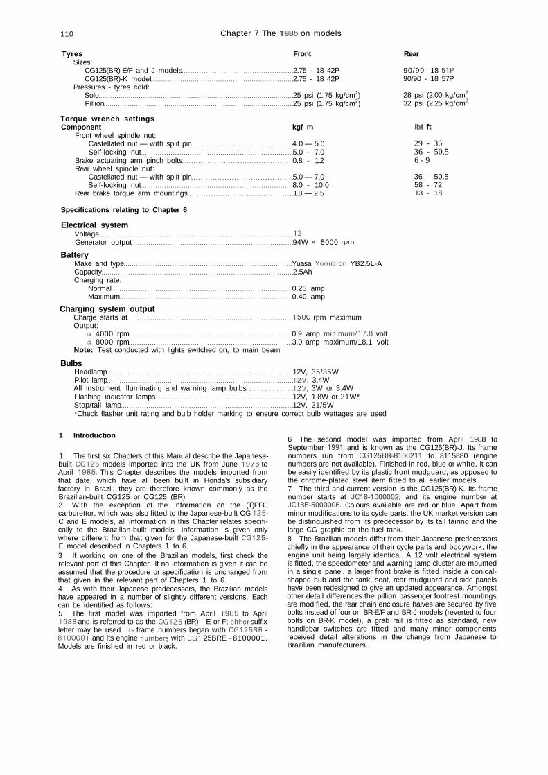
110 Chapter 7 The 1985 on models
Tyres FrontSizes:
CG125(BR)-E/F and J models 2.75 - 18 42PCG125(BR)-K model 2.75 - 18 42P
Pressures - tyres cold:Solo 25 psi (1.75 kg/cm2)Pillion 25 psi (1.75 kg/cm2)
Torque wrench settingsComponent kgf m
Front wheel spindle nut:Castellated nut — with split pin 4.0 — 5.0Self-locking nut 5.0 - 7.0
Brake actuating arm pinch bolts 0.8 - 1.2Rear wheel spindle nut:
Castellated nut — with split pin 5.0 — 7.0Self-locking nut 8.0 - 10.0
Rear brake torque arm mountings 1.8 — 2.5
Specifications relating to Chapter 6
Electrical systemVoltage 12Generator output 94W ® 5000 rpm
BatteryMake and type Yuasa Yumicron YB2.5L-ACapacity 2.5AhCharging rate:
Normal 0.25 ampMaximum 0.40 amp
Charging system outputCharge starts at 1500 rpm maximumOutput:
e 4000 rpm 0.9 amp minimum/17.8 volte 8000 rpm 3.0 amp maximum/18.1 volt
Note: Test conducted with lights switched on, to main beam
BulbsHeadlamp 12V, 35/35WPilot lamp 12V, 3.4WAll instrument illuminating and warning lamp bulbs 12V, 3W or 3.4WFlashing indicator lamps 12V, 1 8W or 21W*Stop/tail lamp 12V, 21/5W*Check flasher unit rating and bulb holder marking to ensure correct bulb wattages are used
Rear
90/90- 18 51P90/90 - 18 57P
28 psi (2.00 kg/cm2
32 psi (2.25 kg/cm2
Ibf ft
29 - 3636 - 50.56 - 9
36 - 50.558 - 7213 - 18
1 Introduction
1 The first six Chapters of this Manual describe the Japanese-built CG125 models imported into the UK from June 1976 toApril 1985. This Chapter describes the models imported fromthat date, which have all been built in Honda's subsidiaryfactory in Brazil; they are therefore known commonly as theBrazilian-built CG125 or CG125 (BR).2 With the exception of the information on the (T)PFCcarburettor, which was also fitted to the Japanese-built CG 125-C and E models, all information in this Chapter relates specifi-cally to the Brazilian-built models. Information is given onlywhere different from that given for the Japanese-built CG125-E model described in Chapters 1 to 6.3 If working on one of the Brazilian models, first check therelevant part of this Chapter. If no information is given it can beassumed that the procedure or specification is unchanged fromthat given in the relevant part of Chapters 1 to 6.4 As with their Japanese predecessors, the Brazilian modelshave appeared in a number of slightly different versions. Eachcan be identified as follows:5 The first model was imported from April 1985 to April1988 and is referred to as the CG125 (BR) - E or F; either suffixletter may be used. Its frame numbers began with CG125BR -8100001 and its engine numbers, with CG1 25BRE - 8100001.Models are finished in red or black.
6 The second model was imported from April 1988 toSeptember 1991 and is known as the CG125(BR)-J. Its framenumbers run from CG125BR-8106211 to 8115880 (enginenumbers are not available). Finished in red, blue or white, it canbe easily identified by its plastic front mudguard, as opposed tothe chrome-plated steel item fitted to all earlier models.7 The third and current version is the CG125(BR)-K. Its framenumber starts at JC18-1000002, and its engine number atJC18E-5000006. Colours available are red or blue. Apart fromminor modifications to its cycle parts, the UK market version canbe distinguished from its predecessor by its tail fairing and thelarge CG graphic on the fuel tank.8 The Brazilian models differ from their Japanese predecessorschiefly in the appearance of their cycle parts and bodywork, theengine unit being largely identical. A 12 volt electrical systemis fitted, the speedometer and warning lamp cluster are mountedin a single panel, a larger front brake is fitted inside a conical-shaped hub and the tank, seat, rear mudguard and side panelshave been redesigned to give an updated appearance. Amongstother detail differences the pillion passenger footrest mountingsare modified, the rear chain enclosure halves are secured by fivebolts instead of four on BR-E/F and BR-J models (reverted to fourbolts on BR-K model), a grab rail is fitted as standard, newhandlebar switches are fitted and many minor componentsreceived detail alterations in the change from Japanese toBrazilian manufacturers.
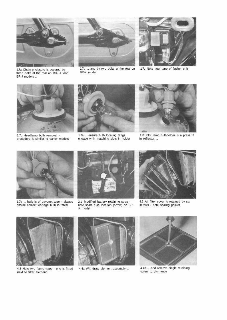
1.7a Chain enclosure is secured bythree bolts at the rear on BR-E/F andBR-J models ...
1.7b ... and by two bolts at the rear on 1.7c Note later type of flasher unitBR-K model
1.7d Headlamp bulb removal -procedure is similar to earlier models
1.7e ... ensure bulb locating tangs 1.7f Pilot lamp bulbholder is a press fitengage with matching slots in holder in reflector ...
1.7g ... bulb is of bayonet type - always 2.1 Modified battery retaining strap -ensure correct wattage bulb is fitted note spare fuse location (arrow) on BR-
K model
4.2 Air filter cover is retained by sixscrews - note sealing gasket
4.3 Note two flame traps - one is fitted 4.4a Withdraw element assembly ...next to filter element
4.4b ... and remove single retainingscrew to dismantle
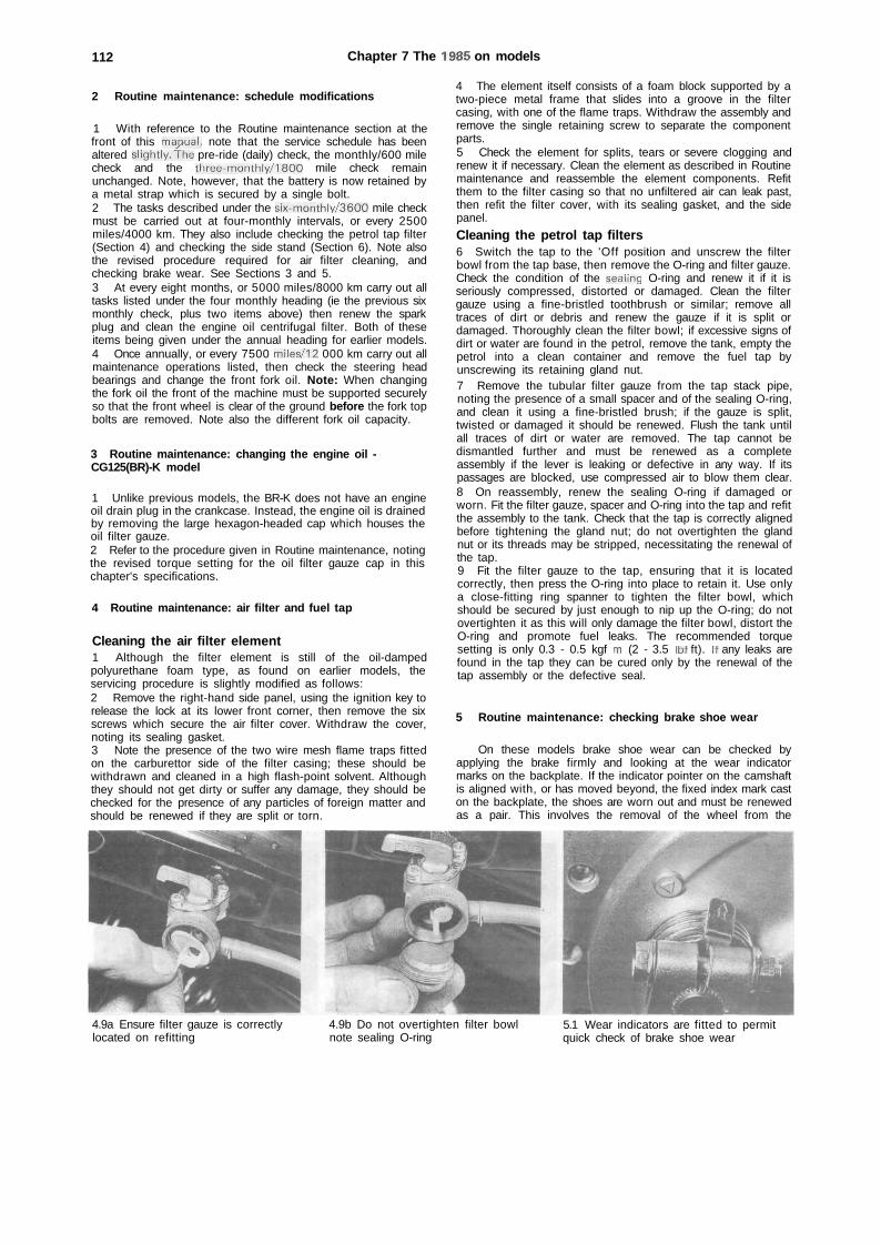
112 Chapter 7 The 1985 on models
2 Routine maintenance: schedule modifications
1 With reference to the Routine maintenance section at thefront of this mapual, note that the service schedule has beenaltered slightly.The pre-ride (daily) check, the monthly/600 milecheck and the three-monthly/1800 mile check remainunchanged. Note, however, that the battery is now retained bya metal strap which is secured by a single bolt.2 The tasks described under the six-monthly/3600 mile checkmust be carried out at four-monthly intervals, or every 2500miles/4000 km. They also include checking the petrol tap filter(Section 4) and checking the side stand (Section 6). Note alsothe revised procedure required for air filter cleaning, andchecking brake wear. See Sections 3 and 5.3 At every eight months, or 5000 miles/8000 km carry out alltasks listed under the four monthly heading (ie the previous sixmonthly check, plus two items above) then renew the sparkplug and clean the engine oil centrifugal filter. Both of theseitems being given under the annual heading for earlier models.4 Once annually, or every 7500 miles/12 000 km carry out allmaintenance operations listed, then check the steering headbearings and change the front fork oil. Note: When changingthe fork oil the front of the machine must be supported securelyso that the front wheel is clear of the ground before the fork topbolts are removed. Note also the different fork oil capacity.
3 Routine maintenance: changing the engine oil -CG125(BR)-K model
1 Unlike previous models, the BR-K does not have an engineoil drain plug in the crankcase. Instead, the engine oil is drainedby removing the large hexagon-headed cap which houses theoil filter gauze.2 Refer to the procedure given in Routine maintenance, notingthe revised torque setting for the oil filter gauze cap in thischapter's specifications.
4 Routine maintenance: air filter and fuel tap
Cleaning the air filter element1 Although the filter element is still of the oil-dampedpolyurethane foam type, as found on earlier models, theservicing procedure is slightly modified as follows:2 Remove the right-hand side panel, using the ignition key torelease the lock at its lower front corner, then remove the sixscrews which secure the air filter cover. Withdraw the cover,noting its sealing gasket.3 Note the presence of the two wire mesh flame traps fittedon the carburettor side of the filter casing; these should bewithdrawn and cleaned in a high flash-point solvent. Althoughthey should not get dirty or suffer any damage, they should bechecked for the presence of any particles of foreign matter andshould be renewed if they are split or torn.
4 The element itself consists of a foam block supported by atwo-piece metal frame that slides into a groove in the filtercasing, with one of the flame traps. Withdraw the assembly andremove the single retaining screw to separate the componentparts.5 Check the element for splits, tears or severe clogging andrenew it if necessary. Clean the element as described in Routinemaintenance and reassemble the element components. Refitthem to the filter casing so that no unfiltered air can leak past,then refit the filter cover, with its sealing gasket, and the sidepanel.
Cleaning the petrol tap filters6 Switch the tap to the 'Off position and unscrew the filterbowl from the tap base, then remove the O-ring and filter gauze.Check the condition of the seaiing O-ring and renew it if it isseriously compressed, distorted or damaged. Clean the filtergauze using a fine-bristled toothbrush or similar; remove alltraces of dirt or debris and renew the gauze if it is split ordamaged. Thoroughly clean the filter bowl; if excessive signs ofdirt or water are found in the petrol, remove the tank, empty thepetrol into a clean container and remove the fuel tap byunscrewing its retaining gland nut.7 Remove the tubular filter gauze from the tap stack pipe,noting the presence of a small spacer and of the sealing O-ring,and clean it using a fine-bristled brush; if the gauze is split,twisted or damaged it should be renewed. Flush the tank untilall traces of dirt or water are removed. The tap cannot bedismantled further and must be renewed as a completeassembly if the lever is leaking or defective in any way. If itspassages are blocked, use compressed air to blow them clear.8 On reassembly, renew the sealing O-ring if damaged orworn. Fit the filter gauze, spacer and O-ring into the tap and refitthe assembly to the tank. Check that the tap is correctly alignedbefore tightening the gland nut; do not overtighten the glandnut or its threads may be stripped, necessitating the renewal ofthe tap.9 Fit the filter gauze to the tap, ensuring that it is locatedcorrectly, then press the O-ring into place to retain it. Use onlya close-fitting ring spanner to tighten the filter bowl, whichshould be secured by just enough to nip up the O-ring; do notovertighten it as this will only damage the filter bowl, distort theO-ring and promote fuel leaks. The recommended torquesetting is only 0.3 - 0.5 kgf m (2 - 3.5 Ibf ft). If any leaks arefound in the tap they can be cured only by the renewal of thetap assembly or the defective seal.
5 Routine maintenance: checking brake shoe wear
On these models brake shoe wear can be checked byapplying the brake firmly and looking at the wear indicatormarks on the backplate. If the indicator pointer on the camshaftis aligned with, or has moved beyond, the fixed index mark caston the backplate, the shoes are worn out and must be renewedas a pair. This involves the removal of the wheel from the
4.9a Ensure filter gauze is correctlylocated on refitting
4.9b Do not overtighten filter bowlnote sealing O-ring
5.1 Wear indicators are fitted to permitquick check of brake shoe wear

Chapter 7 The 1985 on models 113
machine so that the brake components can then be dismantled,cleaned, checked for wear, and reassembled. It is important thatmoving parts such as the brake camshaft are lubricated with asmear of high melting-point grease on reassembly.
6 Routine maintenance: checking the side stand
1 Examine the side stand for cracks or bending, and lubricatethe pivot with a multi-purpose or graphited grease." The sidestand pivots about a single shouldered bolt; check that itsretaining nut is securely fastened. Check the return spring andrenew it, if weak or strained; if the pivot is correctly lubricatedand the spring sufficiently strong, a pull of 2 — 3 kg (4.4 — 6.6Ib) as measured with a spring balance hooked on to the standfoot, should be required to retract the stand when it is in thedown' position (machine supported on centre stand).2 Inspect the rubber pad on the side stand for wear. If it isworn down to or past the wear mark, it should be renewed.Renew with a pad marked Below 259 Ib only'.
7 Compression test: all models
1 At regular intervals it is useful to check the compressionpressure to gain some idea of the degree of engine wear thathas taken place; if engine performance is faulty the compressiontest can be a useful diagnostic aid.2 Engine compression pressure is tested using a compressiongauge with an adaptor suitable for a 1 2 mm spark plug thread.The engine must be fully warmed up, with the valve clearancesaccurately set and all cylinder head retaining nuts tightened tothe correct torque settings. Open fully the throttle twistgrip and
turn the engine over several times with the kickstart, noting thevalues recorded by the gauge.3 If the readings obtained are significantly lower than thosespecified in Chapter 1, the engine is excessively worn and mustbe stripped for repair. The areas of wear are the piston/cylindergroup, the head gasket, or the valves. The piston/cylinder groupcan be checked by removing the gauge, pouring a small amountof oil into the cylinder bore, then repeating the test. If thepressure recorded is significantly increased, the piston, pistonrings or cylinder barrel are at fault; if the pressure remainsunchanged, the head gasket or valves are faulty.4 In the rare event of a pressure being recorded that is higherthan that specified, this ca"n be due only to an excessive build-up of carbon in the combustion chamber, which must beremoved to restore full engine performance. However since it isextremely unlikely that an engine will run for long enough tobuild up such excessive deposits without a proportionateamount of mechanical wear taking place, the cause of such anexcessive build-up must be established and rectified.
8 Engine modifications: general
1 Chapter 1, Section 6 mentions two special Honda servicetools which are required during the dismantling and reassemblyof the engine. Note that the part numbers are changed for theselater models. The centrifugal oil filter nut peg spanner is now07716 - 0020100, and must be used with handle/extensionbar 0771 6 - 0020500. Alternatively a similar tool can easily befabricated as described in Chapter 1. The generator rotorflywheel puller is now 07733 -0010000. Owners should note,however, that much cheaper pattern versions of this puller areavailable which will fit Brazilian- and Japanese-built machines;these pullers will fit nearly all modern small-capacity Japanese
6.2 Side stand rubber pad must berenewed when worn to limit markshown by arrow
8.1a Manufacturer's special tools can be 8.1b ... or by proprietary pattern versionsreplaced by home-made items as such as the flywheel puller shownshown ...
.A / i
8.3a Note slightly modified clutchrelease arm - extract roll pin to permitremoval
8.3b Clutch pushrod is now in onepiece
11.1 Petrol tank rear mounting issecured by a single bolt

114 Chapter 7 The 1985 on models
machines and can be easily obtained from a good motorcycledealer.2 Note that the piston crown marking mentioned in Chapter1, Section 39 is now AD. Its purpose is the same; to identify the(larger) inlet valve cutaway which must face to the rear onreassembly.3 The clutch release mechanism is very slightly modified (seeaccompanying photographs).4 The crankcases and crankcase covers are now secured byhexagon-headed screws which will require the use of a veryslim, deep, 8 mm (spanner size) socket if they are to be removedand refitted without risk of damage. Sockets of the appropriatetype are usually only available in the smaller drive sizes; ensurethat the necessary tools and adaptors are purchased with thesocket.
9 Dismantling and rebuilding the engine/gearbox unit:separating the crankcase halves
1 In Chapter 1 owners are recommended to lift off thecrankcase right-hand half, leaving all internal components in thedeeper left-hand casing.2 For later models, work will be found much easier if thecrankcase left-hand half is lifted off, leaving all components inthe right-hand half.3 On reassembly, therefore, mesh together the gearboxclusters and fit them to their bearings in the crankcase right-hand half. Ensure that all thrust washers are refitted and thatboth shafts rotate freely.4 Refit the gear selector components as described in Section10, then refit the kickstart shaft and crankshaft as described inChapter 1.5 Fit a new gasket over the two locating dowels, lubricate allbearings and refit the crankcase left-hand half, following theinstructions given in Chapter 1.
10 Gear selector mechanism: general
kFWD
Fig. 7.1 Modified selector mechanism components
1 Fork shaft2 Right-hand selector
fork
3 Centre selector fork4 Left-hand selector
fork
See Fig. 1.5 for details of remaining components
1 Although generally unchanged the selector mechanism hasreceived a few detail modifications. Refer to the accompanyingillustration for details.2 On removal, note that the selector fork shaft can bewithdrawn as soon as the crankcase halves have beenseparated. Rotate the forks away from the selector drum,withdraw the drum and then lift out each fork in turn, makingnotes or marks as required to ensure correct identification ofeach fork and of which way up it is fitted.3 On reassembly the right-hand fork should be refitted to thelayshaft 3rd gear pinion, with its marking facing upwards (ie, tothe left). The centre fork is fitted to the mainshaft 4th gearpinion. The left-hand fork is fitted to the layshaft 5th gearpinion, with its marking facing downwards (ie, towards theother forks).4 Insert the selector drum so that the neutral switch contactaligns with the switch terminal and manoeuvre the fork guidepins into their respective grooves. Lubricate and insert theselector fork shaft, then rotate the drum to check that all gearscan be selected, then return to the neutral position.
11 Petrol tank: removal and refitting
The petrol tank rear mounting is now secured by a single boltand washer (see accompanying photograph). On refitting, alwaysensure that the tank rear mounting bracket is settled correctlyon the rubber spacer before tightening the bolt.
12 (T)PFC carburettor: removal - CG125-C, E andBrazilian models
1 First remove its two retaining screws and withdraw thecarburettor cover, then switch off the petrol tap and disconnectthe feed pipe from the tap spigot. Pull the drain tube clear of theengine and frame. Remove the right-hand side panel for extraworking space.2 Slacken the screw clamp which secures the air filter hose tothe carburettor. Slacken the adjuster locknut and unscrew theaccelerator pump cable adjuster from its bracket, then discon-nect the cable end nipple from the pump cam.3 Unscrew the two bolts securing the inlet stub to thecylinder head, then partially withdraw the carburettor assemblyuntil the carburettor top can be unscrewed and the throttlevalve withdrawn.4 The throttle valve assembly can be dismantled as describedin Chapter 2, Section 5. Note that the valve can be detachedeasily with the carburettor in place by removing the seat andeither removing the petrol tank or lifting it at the rear.5 The inlet stub can be detached by removing the two nutswhich secure it to the carburettor. Examine the O-rings at eachend of the stub; these must be renewed to prevent inductionleaks if they are in any way flattened, worn, or damaged.
13 (T)PFC carburettor: overhaul - CG125-C, E andBrazilian models
1 The float bowl can be detached complete with the ac-celerator pump diaphragm and rod assembly in place, ifrequired. All other components of the carburettor are the sameas the later type of carburettor described in Chapter 2; refer,therefore, to that Chapter for all information unless shownbelow. Do not disturb the accelerator pump linkage unlessabsolutely necessary; it is pre-set at the factory and will notrequire adjustment in normal use unless disturbed.
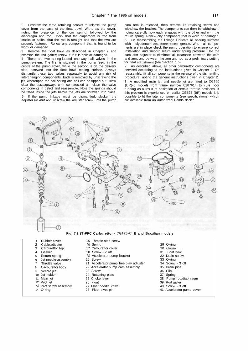
Chapter 7 The 1985 on models 115
2 Unscrew the three retaining screws to release the pumpcover from the base of the float bowl. Withdraw the cover,noting the presence of the coil spring, followed by thediaphragm and rod. Check that the diaphragm is free fromcracks or splits, that the rod is straight and that the two aresecurely fastened. Renew any component that is found to beworn or damaged.3 Remove the float bowl as described in Chapter 2 andexamine the rod gaiter; renew it if it is split or damaged.4 There are two spring-loaded one-way ball valves in thepump system. The first is situated in the pump feed, in thecentre of the pump cover, while the second is on the deliveryside, screwed into the float bowl mating surface. Alwaysdismantle these two valves separately to avoid any risk ofinterchanging components. Each is removed by unscrewing thejet, whereupon the coil spring and ball can be tipped out. Blowclear the passageways with compressed air, clean the valvecomponents in petrol and reassemble. Note the springs shouldbe fitted inside the jets before the jets are screwed into place.5 If the pump linkage must be dismantled, slacken theadjuster locknut and unscrew the adjuster screw until the pump
cam arm is released, then remove its retaining screw andwithdraw the bracket. The components can then be withdrawn,noting carefully how each engages with the other and with thereturn spring. Renew any component that is worn or damaged.6 On reassembling the linkage lubricate all bearing surfaceswith molybdenum disulphide-based grease. When all compo-nents are in place check the pump operation to ensure correctinstallation and smooth return under spring pressure. Use thecam arm adjuster to eliminate all clearance between the camand arm, and between the arm and rod as a preliminary settingfor final adjustment (see Section 1 5).7 As described above, all other carburettor components areserviced according to the instructions given in Chapter 2. Onreassembly, fit all components in the reverse of the dismantlingprocedure, noting the general instructions given in Chapter 2.8 A modified main jet and needle jet are fitted to CG125(BR)-J models from frame number 8107614 to cure poorrunning as a result of hesitation at certain throttle positions. Ifthis problem is experienced on earlier CG125 (BR) models it ispossible to fit the later components (see specifications) whichare available from an authorized Honda dealer.
Fig. 7.2 (T)PFC Carburettor - CG125-C, E and Brazilian models
1234567891011121314
Rubber coverCable adjusterCarburettor topGasketReturn springJet needle assemblyThrottle valveCacburettor bodyNeedle jetJet holderMain jetPilot jetPilot screw assemblyO-ring
15 Throttle stop screw16 Spring17 Carburettor cover18 Screw - 2 off19 Accelerator pump bracket20 Screw21 Accelerator pump free play adjuster22 Accelerator pump cam assembly23 Screw24 Retaining plate25 Choke lever26 Float27 Float needle valve28 Float pivot pin
29 O-ring30 O-ring31 Float bowl32 Drain screw33 O-ring34 Screw - 3 off35 Drain pipe36 Clip37 Spring38 Pump rod/diaphragm39 Rod gaiter40 Screw - 3 off41 Accelerator pump cover
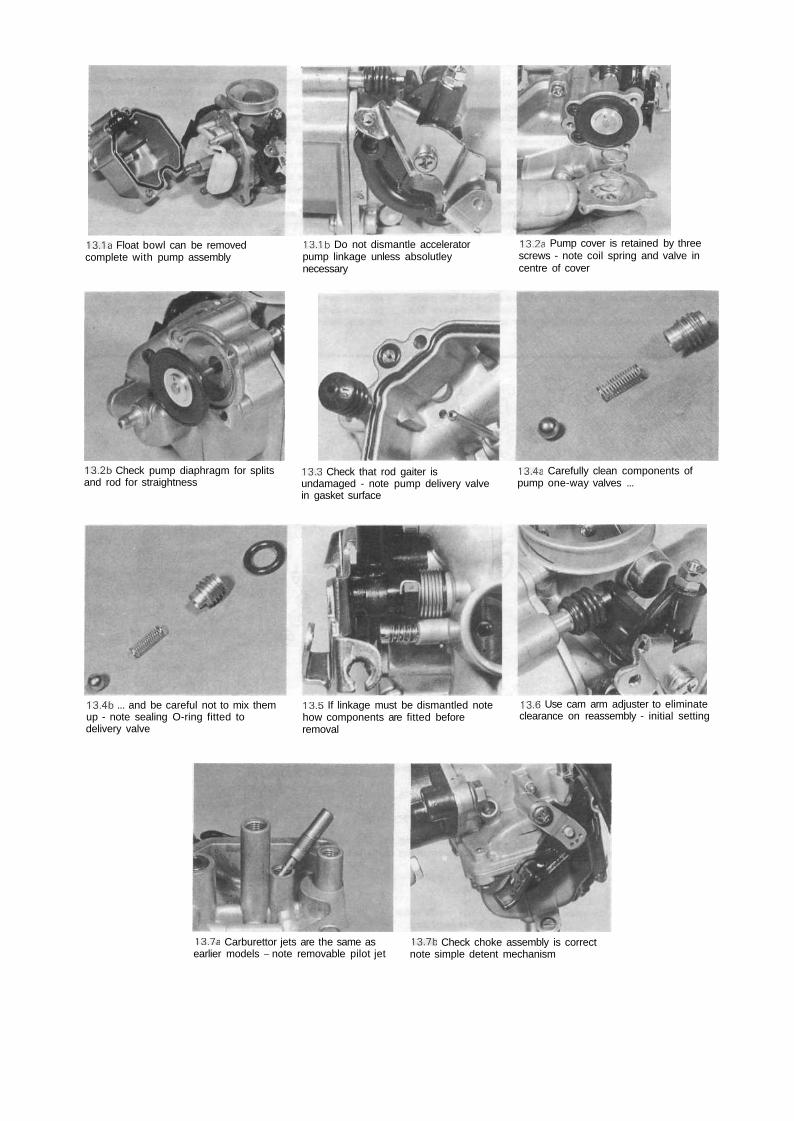
13.1a Float bowl can be removedcomplete with pump assembly
13.1b Do not dismantle acceleratorpump linkage unless absolutleynecessary
13.2a Pump cover is retained by threescrews - note coil spring and valve incentre of cover
13.2b Check pump diaphragm for splitsand rod for straightness
13.3 Check that rod gaiter isundamaged - note pump delivery valvein gasket surface
13.4a Carefully clean components ofpump one-way valves ...
13.4b ... and be careful not to mix themup - note sealing O-ring fitted todelivery valve
13.5 If linkage must be dismantled notehow components are fitted beforeremoval
13.6 Use cam arm adjuster to eliminateclearance on reassembly - initial setting
13.7a Carburettor jets are the same asearlier models - note removable pilot jet
13.7b Check choke assembly is correctnote simple detent mechanism
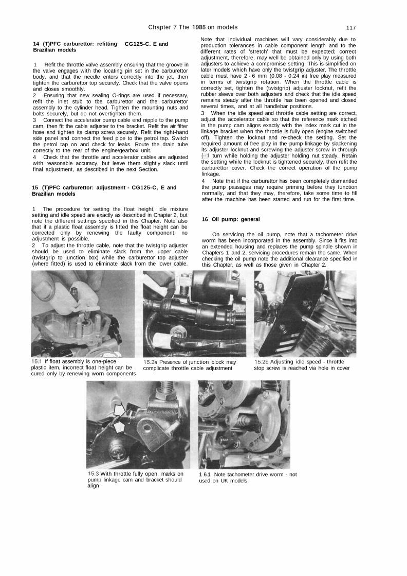
Chapter 7 The 1985 on models 117
14 (T)PFC carburettor: refittingBrazilian models
CG125-C. E and
1 Refit the throttle valve assembly ensuring that the groove inthe valve engages with the locating pin set in the carburettorbody, and that the needle enters correctly into the jet, thentighten the carburettor top securely. Check that the valve opensand closes smoothly.2 Ensuring that new sealing O-rings are used if necessary,refit the inlet stub to tbe carburettor and the carburettorassembly to the cylinder head. Tighten the mounting nuts andbolts securely, but do not overtighten them.3 Connect the accelerator pump cable end nipple to the pumpcam, then fit the cable adjuster to the bracket. Refit the air filterhose and tighten its clamp screw securely. Refit the right-handside panel and connect the feed pipe to the petrol tap. Switchthe petrol tap on and check for leaks. Route the drain tubecorrectly to the rear of the engine/gearbox unit.4 Check that the throttle and accelerator cables are adjustedwith reasonable accuracy, but leave them slightly slack untilfinal adjustment, as described in the next Section.
15 (T)PFC carburettor: adjustment - CG125-C, E andBrazilian models
1 The procedure for setting the float height, idle mixturesetting and idle speed are exactly as described in Chapter 2, butnote the different settings specified in this Chapter. Note alsothat if a plastic float assembly is fitted the float height can becorrected only by renewing the faulty component; noadjustment is possible.2 To adjust the throttle cable, note that the twistgrip adjustershould be used to eliminate slack from the upper cable(twistgrip to junction box) while the carburettor top adjuster(where fitted) is used to eliminate slack from the lower cable.
Note that individual machines will vary considerably due toproduction tolerances in cable component length and to thedifferent rates of 'stretch' that must be expected; correctadjustment, therefore, may well be obtained only by using bothadjusters to achieve a compromise setting. This is simplified onlater models which have only the twistgrip adjuster. The throttlecable must have 2 - 6 mm (0.08 - 0.24 in) free play measuredin terms of twistgrip rotation. When the throttle cable iscorrectly set, tighten the (twistgrip) adjuster locknut, refit therubber sleeve over both adjusters and check that the idle speedremains steady after the throttle has been opened and closedseveral times, and at all handlebar positions.3 When the idle speed and throttle cable setting are correct,adjust the accelerator cable so that the reference mark etchedin the pump cam aligns exactly with the index mark cut in thelinkage bracket when the throttle is fully open (engine switchedoff). Tighten the locknut and re-check the setting. Set therequired amount of free play in the pump linkage by slackeningits adjuster locknut and screwing the adjuster screw in throughj - 1 turn while holding the adjuster holding nut steady. Retainthe setting while the locknut is tightened securely, then refit thecarburettor cover. Check the correct operation of the pumplinkage.4 Note that if the carburettor has been completely dismantledthe pump passages may require priming before they functionnormally, and that they may, therefore, take some time to fillafter the machine has been started and run for the first time.
16 Oil pump: general
On servicing the oil pump, note that a tachometer driveworm has been incorporated in the assembly. Since it fits intoan extended housing and replaces the pump spindle shown inChapters 1 and 2, servicing procedures remain the same. Whenchecking the oil pump note the additional clearance specified inthis Chapter, as well as those given in Chapter 2.
15.1 If float assembly is one-pieceplastic item, incorrect float height can becured only by renewing worn components
15.2a Presence of junction block maycomplicate throttle cable adjustment
15.2b Adjusting idle speed - throttlestop screw is reached via hole in cover
15.3 With throttle fully open, marks onpump linkage cam and bracket shouldalign
1 6.1 Note tachometer drive worm - notused on UK models
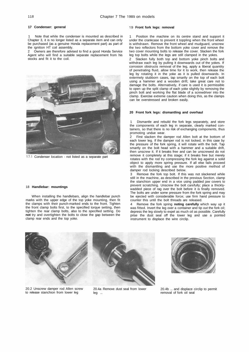
118 Chapter 7 The 1985 on models
17 Condenser: general
1 Note that while the condenser is mounted as described inChapter 3, it is no longer listed as a separate item and can onlybe purchased (as a genuine Honda replacement part) as part ofthe ignition HT coil assembly.2 Owners are therefore advised to find a good Honda ServiceAgent who will find a suitable separate replacement from hisstocks and fit it to the coil.
17.1 Condenser location - not listed as a separate part
18 Handlebar: mountings
When installing the handlebars, align the handlebar punchmarks with the upper edge of the top yoke mounting, then fitthe clamps with their punch-marked ends to the front. Tightenthe front clamp bolts first, to the specified torque setting, thentighten the rear clamp bolts, also to the specified setting. Donot try and overtighten the bolts to close the gap between theclamp rear ends and the top yoke.
19 Front fork legs: removal
1 Position the machine on its centre stand and support itunder the crankcase to prevent it toppling when the front wheelis withdrawn. Remove the front wheel and mudguard, unscrewthe two reflectors from the bottom yoke cover and remove thetwo cover mounting bolts to release the cover. Slacken the forkleg top bolts while the legs are still clamped in the yokes.2 Slacken fully both top and bottom yoke pinch bolts andwithdraw each leg by pulling it downwards out of the yokes. Ifcorrosion obstructs removal of the leg, apply a liberal quantityof penetrating fluid, allow time for it to work, then release theleg by rotating it in the yoke as it is pulled downwards. Inextermely stubborn cases, tap smartly on the top of each boltusing a hammer and a wooden drift; take great care not todamage the bolts. Alternatively, if care is used it is permissibleto open up the split clamp of each yoke slightly by removing thepinch bolt and working the flat blade of a screwdriver into theclamp. Exercise extreme caution when doing this, as the clampscan be overstressed and broken easily.
20 Front fork legs: dismantling and overhaul
1 Dismantle and rebuild the fork legs separately, and storethe components of each leg in separate, clearly marked con-tainers, so that there is no risk of exchanging components, thuspromoting undue wear.2 First slacken the damper rod Allen bolt at the bottom ofeach lower leg. If the damper rod is not locked, in this case bythe pressure of the fork spring, it will rotate with the bolt. Tapsmartly on the bolt head with a hammer and a suitable drift,then unscrew it. If it breaks free and can be unscrewed do notremove it completely at this stage; if it breaks free but merelyrotates with the rod try compressing the fork leg against a solidobject to apply more spring pressure. If all else fails proceedwith the dismantling and use the more positive method ofdamper rod locking described below.3 Remove the fork top bolt. If this was not slackened whilestill in the machine, as described in the previous Section, clampthe stanchion upper end in a vice using padded jaw covers toprevent scratching. Unscrew the bolt carefully; place a thickly-wadded piece of rag over the bolt before it is finally removed.The bolts are under some pressure from the fork spring and maybe ejected with considerable force; use firm hand pressure tocounter this until the bolt threads are released.4 Remove the fork spring noting carefully which way up itwas fitted. Invert the leg over a container and tip out the fork oil;depress the leg slowly to expel as much oil as possible. Carefullyprise the dust seal off the lower leg and use a pointedinstrument to displace the wire circlip.
20.2 Unscrew damper rod Allen screwto release stanchion from lower leg
20.4a Remove dust seal from lowerleg ...
20.4b ... and displace circlip to permitremoval of fork oil seal
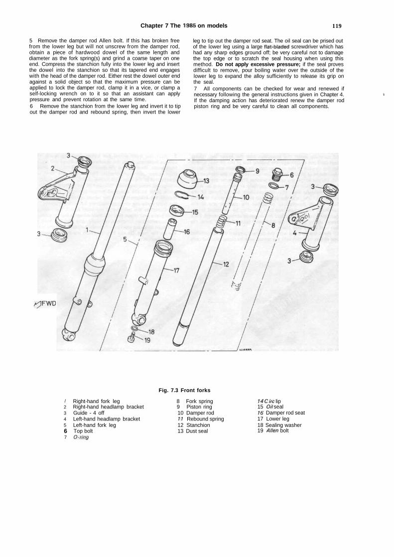
Chapter 7 The 1985 on models 119
5 Remove the damper rod Allen bolt. If this has broken freefrom the lower leg but will not unscrew from the damper rod,obtain a piece of hardwood dowel of the same length anddiameter as the fork spring(s) and grind a coarse taper on oneend. Compress the stanchion fully into the lower leg and insertthe dowel into the stanchion so that its tapered end engageswith the head of the damper rod. Either rest the dowel outer endagainst a solid object so that the maximum pressure can beapplied to lock the damper rod, clamp it in a vice, or clamp aself-locking wrench on to it so that an assistant can applypressure and prevent rotation at the same time.6 Remove the stanchion from the lower leg and invert it to tipout the damper rod and rebound spring, then invert the lower
leg to tip out the damper rod seat. The oil seal can be prised outof the lower leg using a large flat-bladed screwdriver which hashad any sharp edges ground off; be very careful not to damagethe top edge or to scratch the seal housing when using thismethod. Do not apply excessive pressure; if the seal provesdifficult to remove, pour boiling water over the outside of thelower leg to expand the alloy sufficiently to release its grip onthe seal.7 All components can be checked for wear and renewed ifnecessary following the general instructions given in Chapter 4.If the damping action has deteriorated renew the damper rodpiston ring and be very careful to clean all components.
'
A^JFWD
Fig. 7.3 Front forks
/234567
Right-hand fork legRight-hand headlamp bracketGuide - 4 offLeft-hand headlamp bracketLeft-hand fork legTop boltO-ring
8 Fork spring9 Piston ring10 Damper rod11 Rebound spring12 Stanchion13 Dust seal
14 C ire lip15 Oil seal16 Damper rod seat17 Lower leg18 Sealing washer19 Allen bolt
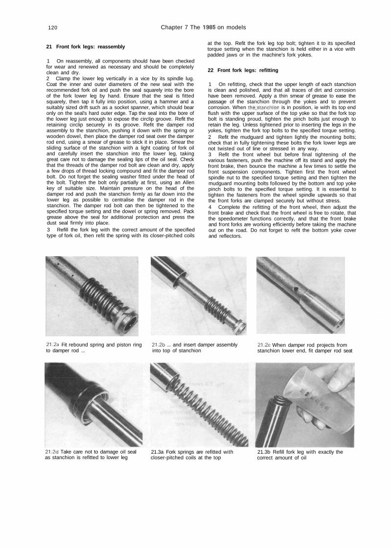
120 Chapter 7 The 1985 on models
21 Front fork legs: reassembly
1 On reassembly, all components should have been checkedfor wear and renewed as necessary and should be completelyclean and dry.2 Clamp the lower leg vertically in a vice by its spindle lug.Coat the inner and outer diameters of the new seal with therecommended fork oil and push the seal squarely into the boreof the fork lower leg by hand. Ensure that the seal is fittedsquarely, then tap it fully into position, using a hammer and asuitably sized drift such as a socket spanner, which should bearonly on the seal's hard outer edge. Tap the seal into the bore ofthe lower leg just enough to expose the circlip groove. Refit theretaining circlip securely in its groove. Refit the damper rodassembly to the stanchion, pushing it down with the spring orwooden dowel, then place the damper rod seat over the damperrod end, using a smear of grease to stick it in place. Smear thesliding surface of the stanchion with a light coating of fork oiland carefully insert the stanchion into the lower leg, takinggreat care not to damage the sealing lips of the oil seal. Checkthat the threads of the damper rod bolt are clean and dry, applya few drops of thread locking compound and fit the damper rodbolt. Do not forget the sealing washer fitted under the head ofthe bolt. Tighten the bolt only partially at first, using an Allenkey of suitable size. Maintain pressure on the head of thedamper rod and push the stanchion firmly as far down into thelower leg as possible to centralise the damper rod in thestanchion. The damper rod bolt can then be tightened to thespecified torque setting and the dowel or spring removed. Packgrease above the seal for additional protection and press thedust seal firmly into place.3 Refill the fork leg with the correct amount of the specifiedtype of fork oil, then refit the spring with its closer-pitched coils
at the top. Refit the fork leg top bolt; tighten it to its specifiedtorque setting when the stanchion is held either in a vice withpadded jaws or in the machine's fork yokes.
22 Front fork legs: refitting
1 On refitting, check that the upper length of each stanchionis clean and polished, and that all traces of dirt and corrosionhave been removed. Apply a thin smear of grease to ease thepassage of the stanchion through the yokes and to preventcorrosion. When the,stanchion is in position, ie with its top endflush with the upper surface of the top yoke so that the fork topbolt is standing proud, tighten the pinch bolts just enough toretain the leg. Unless tightened prior to inserting the legs in theyokes, tighten the fork top bolts to the specified torque setting.2 Refit the mudguard and tighten lightly the mounting bolts;check that in fully tightening these bolts the fork lower legs arenot twisted out of line or stressed in any way.3 Refit the front wheel but before final tightening of thevarious fasteners, push the machine off its stand and apply thefront brake, then bounce the machine a few times to settle thefront suspension components. Tighten first the front wheelspindle nut to the specified torque setting and then tighten themudguard mounting bolts followed by the bottom and top yokepinch bolts to the specified torque setting. It is essential totighten the fasteners from the wheel spindle upwards so thatthe front forks are clamped securely but without stress.4 Complete the refitting of the front wheel, then adjust thefront brake and check that the front wheel is free to rotate, thatthe speedometer functions correctly, and that the front brakeand front forks are working efficiently before taking the machineout on the road. Do not forget to refit the bottom yoke coverand reflectors.
21.2a Fit rebound spring and piston ring 21.2b ... and insert damper assemblyto damper rod ... into top of stanchion
21,2c When damper rod projects fromstanchion lower end, fit damper rod seat
21.2d Take care not to damage oil sealas stanchion is refitted to lower leg
21.3a Fork springs are refitted withcloser-pitched coils at the top
21.3b Refill fork leg with exactly thecorrect amount of oil
•

Chapter 7 The 1985 on models 121
24.3 Press latch on each side to releaseseat (tail fairing will obscure latches onBR-K model)
24.5a Remove grab rail (four bolts), thentwo rear bolts (arrows) ...
24.5b ... followed by four bolts (arrows)to free tail fairing
23 Swinging arm: check, removal and refittingCG125(BR)-K model
Check1 With the machine on its centre stand, grasp both swingingarm ends and attempt to move them from side to side. If asignificant amount of side play exists the bearings should berenewed.
Removal and refitting2 Remove the rear wheel and chainguard as described inChapter 5 (having referred first to Section 26 of this Chapter) anddisconnect the chain. The torque arm should be disconnectedfrom the swinging arm.3 Detach the rear suspension units from their bottom mountingsand lower the swinging arm to the ground.4 Remove the nut and washer from the end of the swingingarm pivot' snart' and' pull'the sliatt out ot'the swinging arm and'frame mountings. The swinging arm is now free.5 Pull the caps off the swinging arm pivot bosses and slide outthe bearing sleeves. If the headed bushes are in need of renewal,the old ones are best withdrawn using a slide-hammer with aninternally expanding adaptor. If using a drift to remove the oldbushes, move it around the inner face to ensure that the bushleaves the housing squarely.6 Clean the housing thoroughly before installing the newbushes. Each bush should be installed with care to preventdamage to its head - the use of a drawbolt and suitably-sizedplain washers is advised to ensure that the bushes enter theirhousing squarely.7 Grease each bearing sleeve and insert them into the bushes.Apply grease to the inner face or the caps and fit them to eachside of the housings. Grease the pivot shaft, then offer up theswinging arm and insert the pivot shaft fully. Install the plainwasher and nut on its opposite end and tighten the nut to thespecified torque setting. Check that the swinging arm is able tomove freely and that there is no discernible side play in the pivot.8 Refit all disturbed components in a reverse of the removalprocedure.
Seat3 The seat is removable to allow easy access to the toolbox,and on BR-K models to the small storage box in the tail fairing.It is secured by two latches, one on each side at the seat's rearend, just behind the suspension unit top mountings. Press eachlatch to the rear to release, and where applicable, unlock thehelmet lock to release the wire clip.4 On refitting, hook the seat front mounting under its locatingbracket and press the seat down at the rear so that its two latchessnap into engagement. Where fitted, slip the wire clip into thehelmet lock to provide a measure of security.
Tail fairing - CG125(BR)-K only5 Remove the seat as described above, then release the grabrail by removing its four mounting bolts. Remove the six tailfairing mounting bolts and manoeuvre it free of the frame.6 Reverse the removal procedure to refit the tail fairing, notingthat a plain washer, damping rubber and spacer must be fitted
25 Speedometer: removal and refitting
1 The speedometer is mounted in a panel with the ignitionswitch and warning lamp cluster. To remove the completeassembly remove the headlamp rim and reflector unit, thentrace and disconnect the wiring from the panel. Disconnect thespeedometer drive cable.2 Unscrew the two bolts which secure the panel to the topyoke, withdraw the panel and unplug the bulb holders.3 Invert the assembly and withdraw the bolts which retainthe mounting bracket, noting the arrangement of washers anddamper rubbers.4 Remove all the small screws which secure the panel topand bottom covers and the warning lamp cluster housing. Thespeedometer head is secured by two screws. When all screwshave been released the various components can be separated.5 Reassembly is the reverse of the dismantling procedure.
26 Wheels: general
24 Side panels, seat and tail fairing: removal and refitting
Side panels1 On all models except the CG125(BR)-K, the side panels aresecured by a simple lock at their lower front mounting points.To release the lock, insert the ignition key into the lock and rotateit until it unlocks. Reverse the procedure on refitting.2 On the CG125(BR)-K model, the side panels are secured bya screw at the lower mounting point. Remove the screw and pullthe panel stubs out of their mounting grommets to release.
1 In spite of its different appearance the front wheel is thesame in layout as those of the earlier models described inChapter 5. Detail changes are shown in the accompanyingillustration. The rear wheel differs only in rim size. Servicingprocedures, therefore, remain the same.2 When removing and refitting wheels, note that some latermodels are fitted with self-locking spindle nuts instead ofhaving castellated nuts and split pins. Ensure that theappropriate torque wrench setting is used on refitting, seeSpecifications.
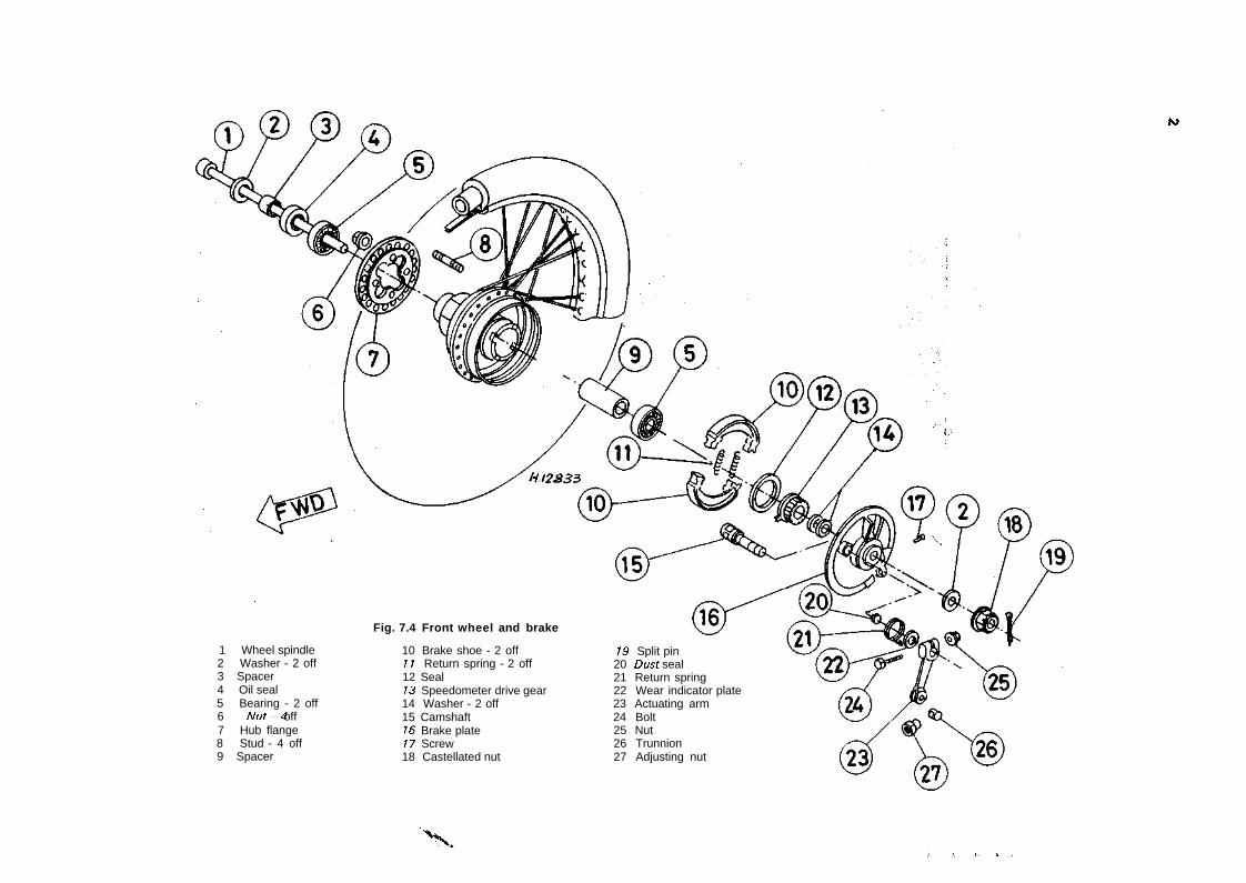
IS)
1 Wheel spindle2 Washer - 2 off3 Spacer4 Oil seal5 Bearing - 2 off6 Nut-4 off7 Hub flange8 Stud - 4 off9 Spacer
Fig. 7.4 Front wheel and brake
10 Brake shoe - 2 off11 Return spring - 2 off12 Seal13 Speedometer drive gear14 Washer - 2 off15 Camshaft16 Brake plate17 Screw18 Castellated nut
19 Split pin20 Dust seal21 Return spring22 Wear indicator plate23 Actuating arm24 Bolt25 Nut26 Trunnion27 Adjusting nut
•"X.} . '>.. J - I r-
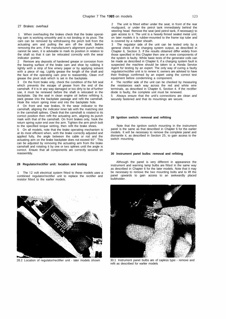
Chapter 7 The 1985 on models 123
27 Brakes: overhaul
1 When overhauling the brakes check that the brake operat-ing cam is working smoothly and is not binding in its pivot. Thecam can be removed by withdrawing the pinch bolt from theactuating arm and pulling the arm off the shaft. Beforeremoving the arm, if the manufacturer's alignment punch markscannot be seen, it is advisable to mark its position in relation tothe shaft so that it can be relocated correctly with the wearindicator pointer.2 Remove any deposits of hardened grease or corrosion fromthe bearing surface of the brake cam and shoe by rubbing itlightly with a strip of fine emery paper or by applying solventwith a piece of rag. Lightly grease the length of the shaft andthe face of the operating cam prior to reassembly. Clean aridgrease the pivot stub which is set in the backplate.3 On the front brake only, check the condition of the felt sealwhich prevents the escape of grease from the end of thecamshaft. If it is in any way damaged or too dirty to be of furtheruse, it must be renewed before the shaft is relocated in thebackplate. Dip the seal in clean engine oil before refitting it,pack grease into the backplate passage and refit the camshaft.Hook the return spring inner end into the backplate hole.4 On front and rear brakes, fit the wear indicator to thecamshaft, aligning the indicator inner tab with the matching slotin the camshaft splines. Check that the camshaft is rotated to itscorrect position then refit the actuating arm, aligning its punchmark with that of the camshaft. On front brakes only, hook thereturn spring outer end over the arm. Tighten the arm pinch boltto the specified torque setting, then refit the brake shoes.5 On all models, note that the brake operating mechanism isat its most efficient when, with the brake correctly adjusted andapplied fully, the angle between the cable or rod and theactuating arm on the brake backplate does not exceed 90°. Thiscan be adjusted by removing the actuating arm from the brakecamshaft and rotating it by one or two splines until the angle iscorrect. Ensure that all components are correctly secured onreassembly.
28 Regulator/rectifier unit: location and testing
1 The 12 volt electrical system fitted to these models uses acombined regulator/rectifier unit to replace the rectifier andresistor fitted to the earlier models.
2 The unit is fitted either under the seat, in front of the rearmudguard, or under the petrol tank immediately behind thesteering head. Remove the seat (and petrol tank, if necessary) togain access to it. The unit is a heavily finned sealed metal unit;on later models it is rubber-mounted to the frame top tube andis covered by a rubber sheath.3 The regulator side of the unit can be tested only by ageneral check of the charging system output, as described inChapter 6, Section 3. If the results obtained differ widely fromthose specified in this Chapter then one or more components ofthe system is faulty. While basic tests of the generator coils canbe made as described in Chapter 6, if a charging system fault issuspected the machine should be taken to a Honda ServiceAgent for testing by an expert. The only way of curing a faultyregulator/rectifier unit is to renew it; owners are advised to havetheir findings confirmed by an expert using the correct testequipment before condemning a component.4 The rectifier side of the unit can be checked by measuringthe resistances each way across the red and white wireterminals, as described in Chapter 6, Section 4. If the rectifierdiode is faulty, the complete unit must be renewed.5 Always ensure that the unit's connections are clean andsecurely fastened and that its mountings are secure.
29 Ignition switch: removal and refitting
Note that the ignition switch mounting in the instrumentpanel is the same as that described in Chapter 6 for the earliermodels. It will be necessary to remove the complete panel anddismantle it, as described in Section 25, to gain access to theswitch mounting.
30 Instrument panel bulbs: removal and refitting
Although the panel is very different in appearance theinstrument and warning lamp bulbs are fitted in the same wayas described in Chapter 6 for the later models. Note that it maybe necessary to remove the two mounting bolts and to lift thepanel upwards to gain access to an awkwardly placedbulbholder.
28.2 Location of regulator/rectifier unit - later models shown 30.1 Instrument panel bulbs are of capless type - remove andrefit as described for earlier models
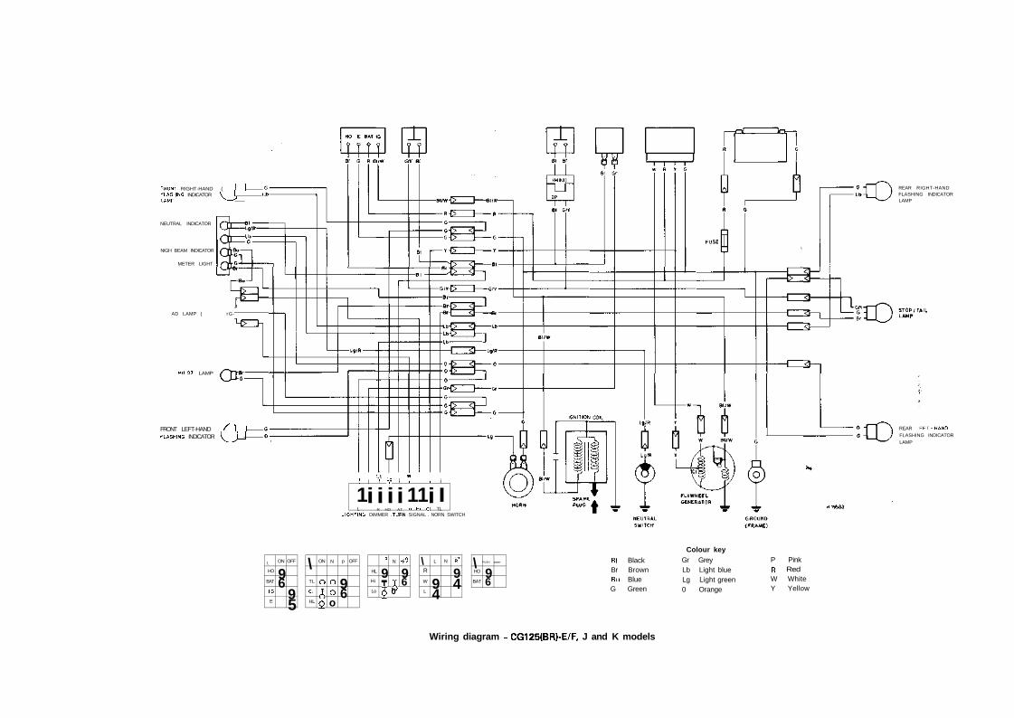
FRONT RIGHT-HAND ( I IPLASHING INDICATOR \ I 1LAMF N — '
NEUTRAL INDICATOR
NIGH BEAM INDICATOR
METER LIGHT
AD LAMP ( rG-
P1LOT LAMP
FRONT LEFT-HAND f 1 IL̂ASHING INDICATOR \ ^ J _ J
1
1L
|
iLb1
iR
Ti
HO
1
iAT
W1
1Lo
1Hi
1
iC l
i
ITL
REAR RIGHT-HANDFLASHING INDICATORLAMP
REAR LEFT-HANDFLASHING INDICATORLAMP
LIGHTING. DIMMER .TURN SIGNAL . NORN SWITCH
\
HO
BAT
IG
E
ON
96
OFF
95
\TL
Cl
HL
ON
o
69
N
ooo
p
96
OFF
HL
Hi
Lo
Q
9Tif
N
50
HiS
96
\R
W
L
L
94
N R*
94
\HO
BAT
PUSH
96
FREE Bl BlackBr BrownBu BlueG Green
Colour keyGr GreyLb Light blueLg Light green0 Orange
P PinkR RedW WhiteY Yellow
Wiring diagram - CG125(BR)-E/F, J and K models
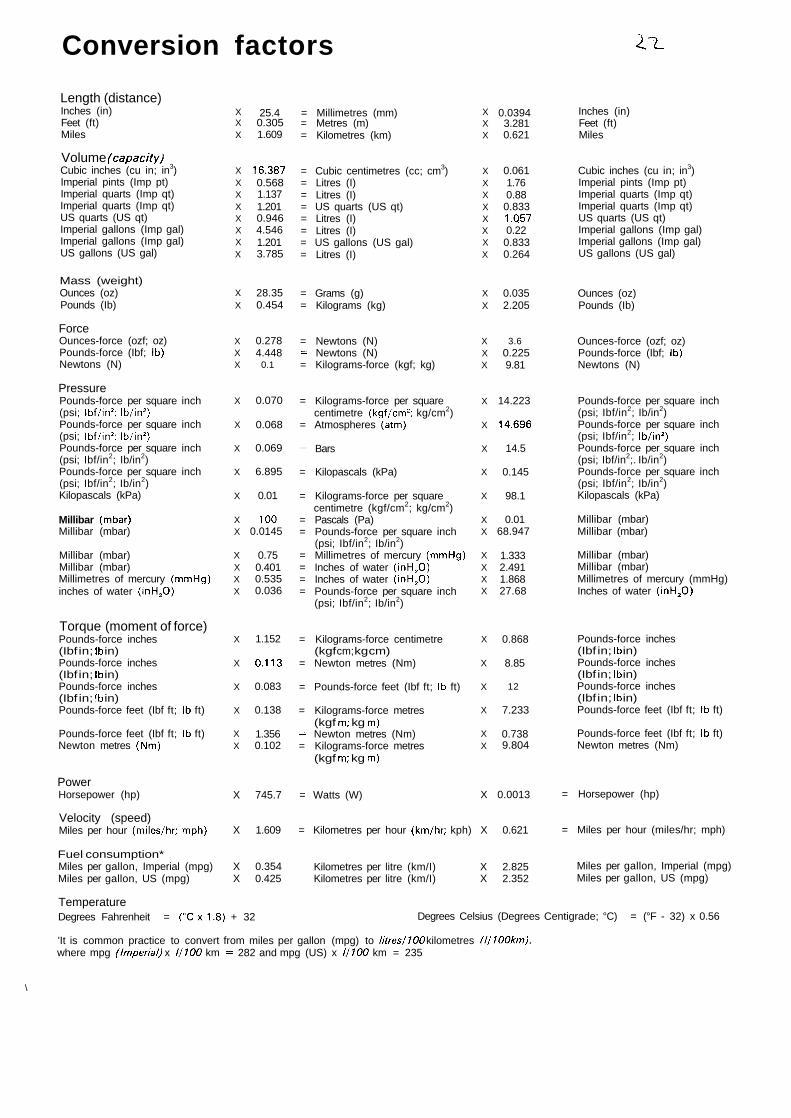
Conversion factors li.
Length (distance)Inches (in)Feet (ft)Miles
Volume (capacity)Cubic inches (cu in; in3)Imperial pints (Imp pt)Imperial quarts (Imp qt)Imperial quarts (Imp qt)US quarts (US qt)Imperial gallons (Imp gal)Imperial gallons (Imp gal)US gallons (US gal)
Mass (weight)Ounces (oz)Pounds (Ib)
ForceOunces-force (ozf; oz)Pounds-force (Ibf; Ib)Newtons (N)
PressurePounds-force per square inch(psi; Ibf/in2; Ib/in2)Pounds-force per square inch(psi; Ibf/in2; Ib/in2)Pounds-force per square inch(psi; Ibf/in2; Ib/in2)Pounds-force per square inch(psi; Ibf/in2; Ib/in2)Kilopascals (kPa)
Millibar (mbar)Millibar (mbar)
Millibar (mbar)Millibar (mbar)Millimetres of mercury (mmHg)inches of water (inH2O)
Torque (moment of force)Pounds-force inches(Ibf in; Ib in)Pounds-force inches(Ibf in; Ib in)Pounds-force inches(Ibf in; Ib in)Pounds-force feet (Ibf ft; Ib ft)
Pounds-force feet (Ibf ft; Ib ft)Newton metres (Nm)
PowerHorsepower (hp)
Velocity (speed)Miles per hour (miles/hr; mph)
Fuel consumption*Miles per gallon, Imperial (mpg)Miles per gallon, US (mpg)
XXX
XXXXXXXX
XX
XXX
X
X
X
X
X
XX
XXXX
X
X
X
X
XX
25.40.3051.609
16.3870.5681.1371.2010.9464.5461.2013.785
28.350.454
0.2784.448
0.1
0.070
0.068
0.069
6.895
0.01
1000.0145
0.750.4010.5350.036
1.152
0.113
0.083
0.138
1.3560.102
= Millimetres (mm)= Metres (m)= Kilometres (km)
= Cubic centimetres (cc; cm3)= Litres (I)= Litres (I)= US quarts (US qt)= Litres (I)= Litres (I)= US gallons (US gal)= Litres (I)
= Grams (g)= Kilograms (kg)
= Newtons (N)= Newtons (N)= Kilograms-force (kgf; kg)
= Kilograms-force per squarecentimetre (kgf/cm2; kg/cm2)
= Atmospheres (atm)
= Bars
= Kilopascals (kPa)
= Kilograms-force per squarecentimetre (kgf/cm2; kg/cm2)
= Pascals (Pa)= Pounds-force per square inch
(psi; Ibf/in2; Ib/in2)= Millimetres of mercury (mmHg)= Inches of water (inH20)= Inches of water (inH20)= Pounds-force per square inch
(psi; Ibf/in2; Ib/in2)
= Kilograms-force centimetre(kgf cm; kg cm)
= Newton metres (Nm)
= Pounds-force feet (Ibf ft; Ib ft)
= Kilograms-force metres(kgf m; kg m)
= Newton metres (Nm)= Kilograms-force metres
(kgf m; kg m)
XXX
XXXXXXXX
XX
XXX
X
X
X
X
X
XX
XXXX
X
X
X
X
XX
0.03943.2810.621
0.0611.760.880.8331.0570.220.8330.264
0.0352.205
3.60.2259.81
14.223
14.696
14.5
0.145
98.1
0.0168.947
1.3332.4911.86827.68
0.868
8.85
12
7.233
0.7389.804
X 745.7 = Watts (W) X 0.0013
X 1.609 = Kilometres per hour (km/hr; kph) X 0.621
X 0.354X 0.425
Kilometres per litre (km/I) X 2.825Kilometres per litre (km/I) X 2.352
Inches (in)Feet (ft)Miles
Cubic inches (cu in; in3)Imperial pints (Imp pt)Imperial quarts (Imp qt)Imperial quarts (Imp qt)US quarts (US qt)Imperial gallons (Imp gal)Imperial gallons (Imp gal)US gallons (US gal)
Ounces (oz)Pounds (Ib)
Ounces-force (ozf; oz)Pounds-force (Ibf; Ib)Newtons (N)
Pounds-force per square inch(psi; Ibf/in2; Ib/in2)Pounds-force per square inch(psi; Ibf/in2; Ib/in2)Pounds-force per square inch(psi; Ibf/in2;. Ib/in2)Pounds-force per square inch(psi; Ibf/in2; Ib/in2)Kilopascals (kPa)
Millibar (mbar)Millibar (mbar)
Millibar (mbar)Millibar (mbar)Millimetres of mercury (mmHg)Inches of water (inH20)
Pounds-force inches(Ibf in; Ib in)Pounds-force inches(Ibf in; Ib in)Pounds-force inches(Ibf in; Ib in)Pounds-force feet (Ibf ft; Ib ft)
Pounds-force feet (Ibf ft; Ib ft)Newton metres (Nm)
= Horsepower (hp)
= Miles per hour (miles/hr; mph)
Miles per gallon, Imperial (mpg)Miles per gallon, US (mpg)
TemperatureDegrees Fahrenheit = (°Cx1.8) + 32 Degrees Celsius (Degrees Centigrade; °C) = (°F - 32) x 0.56
\
'It is common practice to convert from miles per gallon (mpg) to litres/100 kilometres (1/100km),where mpg (Imperial) x 1/100 km = 282 and mpg (US) x 1/100 km = 235

126
Index
Acknowledgements 2Adjustments
brakes 12, 83,86, 112carburettor 54, 117clutch 12contact breaker points 10, 61final drive chain 9, 87ignition timing 11, 62spark plug 63steering head bearings 12valve clearances 10, 46
Air filter 10, 57Automatic timing unit 61
BBattery
charging and maintenance 95check 9specifications 93,110
Bearingsengine
big-end 30main 30small-end 31
gearbox 30steering head 12, 69wheel
front 83rear 86
Brakesadjustment 12, 83, 86check 8, 112examination and renovation
front 81,121rear 85, 121
fault diagnosis 92pedal - rear 77specifications 80, 109stop lamp 97, 99
Bulbsflashing indicator 99headlamp 97instrument 99,123specifications 93,110tail/stop lamp 97
Cablebrake 12, 83clutch 12lubrication 11speedometer 78throttle 54, 117
Cam gear and shaftexamination and renovation 34refitting 44removal 23
Carburettoradjustment 54,117overhaul 54,114refitting 117removal 53,114settings 54
Chain - final drive 9, 89Charging system 94Clutch
adjustmentsexamination and renovation 34fault diagnosis 51modifications 113refitting 42removal 25specifications 16
Coil - HT 62Compression test 113Condenser 63, 118Contact breaker 10, 61Conversion factors 125Crankcases
joining 40, 119separating 27, 199
Crankshaftbearings 30, 31refitting 35removal 27
Crankshaft pinionexamination and renovation 34refitting 40removal 25
Cush drive - rear wheel 86Cylinder barrel
examination and renovation 32refitting 46removal 19
Cylinder headexamination and renovation 32, 34refitting 46removal 19

127
'Decarbonising 34Dimensions 5, 107Dualseat78, 121
Electrical systembattery 9, 95charging system 94check 93fault diagnosis 102flashing indicators 99fuse 100headlamp 97, 99horn 100rectifier 94regulator/ rectifier 121resistor 100specifications 93, 109
; speedometer 78, 99, 121, 123I wiring 101I wiring diagrams 103-105, 124Engine< bearings 30, 31. cam gear and shaft 23, 34, 44j cases and covers 35
compression test 113crankcases 27, 40, 119crankshaft 27, 30, 35crankshaft pinion 25, 34, 40cylinder barrel 19, 32, 46cylinder head 19, 32, 34, 46decarbonising 34dismantling - general 19examination and renovation - general 27fault diagnosis 50modifications 113oil
change 9. filter
centrifugal type 13, 23, 42, 57gauze type 9, 57
level check 8pump 23, 34, 40, 57, 117
piston 19,31,46pushrods 34reassembly - general 35refitting into the frame 47removal from the frame 17rocker arms 34specifications 15, 107starting and running the rebuilt engine 50valves 10, 32
Khaust system 57
lult diagnosisbrakes 92clutch 51electrical system 102engine 50frame and forks 79fuel system 59gearbox 51
ignition system 66lubrication system 59tyres 92wheels 92
Filterair 10, 57engine oil
centrifugal type 13, 23, 42, 57gauze type 9, 57
Final drive chaincheck 9examination, adjustment and lubrication 89
Flashing indicators 99Flywheel generator see GeneratorFootrests 77Frame 74Front brake
adjustment 12, 83, 112check 8, 112examination and renovation 81,121stop lamp 97, 99
Front forkdismantling, examination and
renovation 69, 73,118oil change 13refitting 73, 120removal 67, 69, 118yokes 69
Front wheelbearings 83examination and renovation 80modifications 121refitting 83removal 81
Fuel systemcarburettor 53-55, 114-117check 11fault diagnosis 59petrol pipe 52petrol tank 52, 114petrol tap 53specifications 52, 108
Fuse 100
Gearboxbearings 30examination and renovation 35fault diagnosis 51shafts
refitting 35 'removal 27
specifications 17,108Gearchange mechanism
modifications 114refitting 40removal 25
Generatoroutput check 60, 94refitting 44removal 22
Headlamp 97, 99Horn 100HT coil 62
Ignition systemATU61condenser 63,118contact breaker points 10, 61fault diagnosis 66HT coil 62sparkplug 10,12, 63, 65specifications 60,108switch 100, 123timing 10, 62
Instrument panel 78, 99, 121, 123
KKickstart mechanism
examination and renovation 35refitting 36removal 27
Lampsflashing indicator 99headlamp 97instrument 99, 123specifications 93, 110tail/stop lamp 97
Legal check 9
MMain bearings 30Maintenance - routine 8-13, 110-112
N
HHandlebars 68, 118
Neutral switchrefitting 44removal 27
Oil - engine/transmissionchange 9filter
centrifugal type 13 ,23, 42, 57gauze type 9, 57
level check 8Oil-front forks 13Oil pump
examination and renovation 34, 57modification 117refitting 40, 57removal 23, 57

128
h
Parts - ordering 6Pedal - rear brake 77Petrol
pipe 52tank 52, 114tap 53
Pistonexamination and renovation 31modifications 113refitting 46removal 19
Primary drive pinionexamination and renovation 34refitting 40.removal 25
Pushrods 34
Rear brakeadjustment 12, 86,112examination and
renovation 85,121pedal 77stop lamp 97, 99
Rear suspension units 76Rear wheel
bearings 86examination and renovation 84modifcations 121refitting 91removal 84sprocket and cush drive 86
Rectifier 94Regulator/rectifier 121Resistor 100Rings - piston 31Rocker arms 34Routine maintenance 8-13,110-112
Safety precautions 7, 9Seat 78, 121Spare parts - ordering 6Sparkplug 10, 12, 63Specifications
brakes 80,109clutch 16electrical system 93,109engine 15, 107frame and forks 67, 109fuel system 52, 108gearbox 17,108ignition system 60, 108maintenance 13, 107tyres 80,109wheels 80,109
Speedometerbulbs 99, 123cable 78head 78, 121
Sprocketengine
refitting 44removal 17
rear wheel 86Stand
main 77side 112
Steeringfault diagnosis 79head bearings 12, 69lock 78
Stop lamp 97, 99Suspension
check 12fault diagnosis 79front forks 13, 67, 69, 73, 118, 120rear units 76specifications 67, 109
Swinging arm 74Switches
brake stop lamp 99
headlamp 99ignition 100, 123neutral 27, 44
Tail lamp 97Timing - ignition 10, 62Tools 14Tyres
check 9fault diagnosis 92removal and refitting 91specifications 80, 109
Valve - engineclearance 10, 46removal, examination and renovation 32
Valve - tyre 91
wWeights 5, 107Wheels
check 12fault diagnosis 92front
bearings 83examination and renovation 80refitting 83removal 81
modifications 121rear
bearings 86examination and renovation 84refitting 91removal 84
specifications 80, 109Wiring
diagrams 103-105, 124layout and examination 101
Working conditions 14