honeywell: endurance valve test - cefns.nau.edu · pdf filethis report was prepared by ... the...
TRANSCRIPT

Honeywell: Endurance Valve Test
Team 30
Bianka Camacho
Lance Gomez
Geordie Macdonald
Garrett Murphy
Cameron Schlatter
Dustin Young
2016-17
Project Sponsor: Honeywell
Faculty Advisor: David Trevas
Sponsor Mentor: Mike McCollum and Mitchell Thune
Instructor: David Trevas
1

DISCLAIMER This report was prepared by students as part of a university course requirement. While considerable effort has been put into the project, it is not the work of licensed engineers and has not undergone the extensive verification that is common in the profession. The information, data, conclusions, and content of this report should not be relied on or utilized without thorough, independent testing and verification. University faculty members may have been associated with this project as advisors, sponsors, or course instructors, but as such they are not responsible for the accuracy of results or conclusions.
2

EXECUTIVE SUMMARY
The scope of this project is to implement gem-like materials into a pneumatic control valve to maximize the life of the valve. By increasing the life of the valve using a tougher material, the valve will be capable of being used in a wider variety of applications. The material selected must be capable of withstanding 10 million cycles at a frequency of 10 Hz with minimal wear. The current materials used in industry include steel and ceramics, which fail significantly faster than the requirements. The original project description called for a ruby ball and sapphire seats. However, the team implemented a Polycrystalline Diamond (PCD) material into a poppet and seat design. The valve is actuated using a Pulse Width Modulated (PWM) solenoid, which is powered through an Arduino microprocessor. In order to document the wear on the material, the team performs a leak down test using a pressure transducer at set intervals. This tracks the change in pressure over time through the seat with a designated control volume. Shown below, in Figure 1, is a plot of our measured pressure leakage versus the number of cycles.
Figure 1: Plotted Data of Leakage vs. number of cycles
The diamond proved to be resilient throughout the testing, and showed no signs of increased pressure leakages over the course of the 10 million cycles. the data does not appear completely linear due to alignment issues with the testing apparatus, but they are within 1% of each other. The team would have liked to continue the testing past the 10 million cycle mark to see when noticeable wear would occur, but could not continue due to the semester ending.
3

ACKNOWLEDGEMENTS
The team would like to acknowledge the Honeywell project sponsors, Mike McCollum, Mike Downey and Haley Flenner, for all their support and guidance throughout the course of this project. The team would also like acknowledge and give special thanks to Sam Wilding, Regan Burton, and Marc Modersitzki for their commitment and dedication to obtain successful results.
4

TABLE OF CONTENTS DISCLAIMER TABLE OF CONTENTS 1 BACKGROUND
1.1 Introduction 1.2 Project Description 1.3 Original System
2 REQUIREMENTS 2.1 Customer Requirements (CRs) 2.2 Engineering Requirements (ERs) 2.3 Testing Procedures (TPs)
2.4.1 Testing Procedure #1: Stroke 2.4.2 Testing Procedure #2: Ball/Poppet Diameter 2.4.3 Testing Procedure #3: Seat Diameter 2.3.4 Testing Procedure #4 Sealing Force 2.4.5 Testing Procedure #5 Inlet Pressure 2.4.6 Testing Procedure #6 Actuation Frequency 2.4.7 Testing Procedure #7 Contact Angle 2.4.8 Testing Procedure #8 Control Volume
2.4 Design Links (DLs) 2.4.1 Design Link #1: Stroke 2.4.2 Design Link #2: Ball/Poppet Diameter 2.4.3 Design Link #3: Seat Diameter 2.3.4 Design Link #4 Sealing Force 2.4.5 Design Link #5 Inlet Pressure 2.4.6 Design Link #6 Actuation Frequency 2.4.7 Design Link #7 Contact Angle 2.4.8 Design Link #8 Control Volume
2.5 House of Quality (HoQ) 3 EXISTING DESIGNS
3.1 Design Research 3.2 System Level
3.2.1 Existing Design #1: Pneumatic Valve Actuator 3.2.2 Existing Design #2: Mechanical Actuator 3.2.3 Existing Design #3: Hydraulic Actuator System
3.3 Subsystem Level 3.3.1 Subsystem #1: Push-Rod Mechanism
3.3.1.1 Existing Design #1: Electromagnetic Push-Rod Actuator 3.3.1.2 Existing Design #2: Rotational Piston Mechanism 3.3.1.3 Existing Design #3: Poppet System
3.3.2 Subsystem #2: Leakage Detector 3.3.2.1 Existing Design #1: Helium Leak Detector 3.3.2.2 Existing Design #2: Pressure Transducer 3.3.2.3 Existing Design #3: Bubbles in Water
3.3.3 Subsystem #3: Chamber and Ball Materials 3.3.3.1 Existing Design #1: Steal
5

3.3.3.2 Existing Design #2: Ceramic 3.3.3.3 Existing Design #3: Aluminum
4 DESIGNS CONSIDERED 4.1 Design #1: Motorized Cam Actuator 4.2 Design #2: Rotating Disk Pressurizing Valve 4.3 Design #3: Proportional Solenoid Actuated Three-Way Valve 4.4 Design #4: Ball and Poker 4.5 Design #5:Helium Leak Detector 4.6 Design #6: Pressure Transducer 4.7 Design #7: Manometer 4.8 Design #8: Synthetic Diamond Poppet 4.9 Design #9: Guide Fingers
5 DESIGN SELECTED 5.1 Rationale for Design Selection 5.2 Design Description
6 PROPOSED DESIGN 7 IMPLEMENTATION 7.1 Design of Experiments 7.2 Design of Experiments 7.3 Design Changes
7.3.1 Poppet Design 7.3.2 Housing 7.3.3 Test Parameters 7.3.4 Leak Down Test
8 TESTING 8.1 Apparatus Testing Procedures 8.2 Testing Results 9 CONCLUSION 9.1 Contributors to Project Success 9.2 Opportunities/ Areas for Improvement 10 REFERENCES APPENDICES
6

1 BACKGROUND 1.1 Introduction Honeywell, a major manufacturer of avionic parts for both civil and military applications designed a theory that they want our Capstone team to test. The theory revolves around using a ruby ball and sapphire seats, or ceramic materials in a pulse width modulation (PWM) solenoid to increase the amount of cycles that can be accomplished before wear causes too much pressure leakage to properly function. After further discussion with Honeywell we learned that they don’t want to limit our group to using these gems, but want the idea tested that hard ceramic materials will increase the lifetime of the solenoid. The purpose for increasing the lifetime of these solenoids is to further diversify their applications. Currently, Honeywell uses these PWM solenoids in missiles to guide the wings throughout the flight to ensure it hits its target. These solenoids are build with stainless steel internals and only live as long as the missile travels, which never exceeds 20 minutes. Since the frequency of these solenoids is 800 Hz, the maximum number of cycles completed in one flight if operating 100% of the time is 960,000 cycles. Honeywell mentioned in our problem statement that these things never operate 100% of the time while in flight, and that currently the internals still manage to degrade over these short cycles.
Our group was tasked with building a replica pneumatic valve that mimics the pre-existing PWM solenoid valve that can recreate realistic conditions in order to test ceramic material internals. The main goal was to produce a combination of internals that can withstand 10 million cycles or more, and to track the leakage vs time. This leakage occurs at the inlet and vent seats as they degrade over the testing. If our team succeeds and we can prove Honeywell's initial theory that ceramic materials are indeed applicable for increasing the pulse width modules lifetime, they intend to invest into further design of these PWM solenoids. These finalized designs would make their ways into jet engines to keep the air turbine to continue turning after landing to cool the engine components and keep them from bowing. Once grounded the internals of the engines bow and force them to be grounded for long periods of time while the bowed parts cool.
1.2 Project Description Following is the original project description provided by the sponsor.
“The task is to research the market to find balls and seats made from gemlike materials with which to construct a test fixture capable of cycling the pneumatic switcher components under realistic conditions for a ten million cycle endurance test.”
The scope of this project is to determine if gem like materials are capable of withstanding 10 million cycles. The team will start this project with research of relevant, gem-like materials similar to ruby and sapphire, to construct the ball and seat for a pneumatic switcher. The team will design and construct a pneumatic control valve in order to test and cycle the materials chosen. Honeywell will have the team create a graph of cycles versus air leakage from the seats to measure the life expectancy of the chosen materials. Figure 1 shows the initial three way actuator.
7

Figure 1: 3-Way Valve Schematic
1.3 Original System This project involves the design of a completely new ball and seat constructed from gem-like materials for pneumatic control valves that will be applied to PWM solenoids. Honeywell has not created a system like this before because their applications are currently designed for 250,000 cycles. Our system will require 10,000,000 cycles, thus the need for new materials to withstand the cyclic loading. An actual ball design however, has been recently been eliminated.Instead a hemispherical poppet design will be implemented. Manufacturing processes for perfect spheres is difficult and many other characteristics of the popper design are more desireable than the ball. This is the idea of connecting the ball to the push-rod, and extending the ball into a cylinder with a hemisphere at each end, acting exactly as the ball would when pushed against the seals. The similar geometry allows for calculations to be made as though we were still working with a ball. Having said that, balls and poppets are mentioned interchangeably throughout the report.
2 REQUIREMENTS
8

2.1 Customer Requirements (CRs) The customer requirements are shown in the House of Quality (HoQ) Table 1, located in Appendix A, along with the weightings.While all the requirements must be taken into account, the requirements that are of top priority are highlighted in the HoQ chart. From the customer requirements, building the testing apparatus as well as completing the project in a timely manner are crucial to the design process and the team’s partnership with Honeywell. The team must aim to first design and build an apparatus in order to provide proper documentation of testing and prove that the sapphire seat and ruby ball combination is feasible and therefore capable of cycling through at least 10 million cycles. However, the team has been looking into implementing synthetic diamonds into the design to ultimately have the valve cycle over the 10 million cycle goal.
In the past, the pneumatic control valves were designed with stainless steel components that caused excessive wear, and therefore, limited the life of the part to short term applications. Honeywell predicts that extremely hard ceramic materials such as rubies and sapphires can extend the life of these valves to that of long term part specifications. It is important to construct a durable fixture capable of withstanding a full testing period. In order to cycle the valve at 10 Hz for 10 million cycles, several weeks are needed for testing in order to ensure periodic pressure measurements. It is imperative that the team utilizes a work breakdown schedule in order to design, build, and test the valve. The time frame of the project is critical to the success of the team, which is why it is the highest weighed requirement.
2.2 Engineering Requirements (ERs) The House of Quality (HoQ) engineering requirements are derived from Honeywell’s original valve constraints. After meeting with the client over skype, the team was informed that the original specifications for the stroke, ball diameter, and materials were up to the team to design, and that the dimensions of the valve were only an example of what could be constructed. Only the control volume, inlet pressure, spring force on pushrod, contact angle between the ball and seats, and the testing frequency were constrained numerically. The inlet pressure must be a constant 50 psi in order to steadily pressurize the valve, while the spring on the actuator must deliver 2-5 lbf in order to steadily depressurize the valve. By keeping the valve cycling at steady state, the air turbine starter valve can keep motoring the engine at low enough speeds to keep the engine cool, while saving expensive hot ram air.
2.3 Testing Procedures (TPs) 2.3.1 Testing Procedure #1: Stroke
To test the stroke of the poker, the displacement of the spring will be measured. (Measurement device will be purchased)
2.3.2 Testing Procedure #2: Ball/Poppet Diameter To test the stroke of the poker, the displacement of the spring will be measured. (Measurement device will be purchased)
2.3.3 Testing Procedure #3: Seat Diameter Calipers will be used to test/measure the dimensions of the seat to be chosen. (Collaboration with manufacturer, calipers also purchased to ensure quality)
2.3.4 Testing Procedure #4: Sealing Force
To test the sealing force of the testing fixture, a force gauge will be used. (Pressure transducer will be purchased)
9

2.3.5 Testing Procedure #5: Inlet Pressure To test the inlet pressure, a pressure gauge will be used. (Pressure transducer will be purchased)
2.3.6 Testing Procedure #6: Actuation Frequency
The actuation frequency will be measured using a function generator in an oscilloscope (School for oscilloscope)
2.3.7 Testing Procedure #7: Contact Angle
To measure the contact angle, the team will ensure that the diameter of the ball is equal to the diameter of the seat. (Calipers will be bought)
2.3.8 Testing Procedure #8: Control Volume Control volume (Multiple ways to test, liquid and measuring cups purchased)
2.4 Design Links (DLs) 2.4.1 Design Link #1: Stroke A stroke of about 0.4mm from top seat to bottom seat will be used. 2.4.2 Design Link #2: Ball Diameter A ball diameter of 3mm will be used in our design. Many calculations were based around this value. 2.4.3 Design Link #3: Seat Diameter The ball diameter to seat diameter is 1.42, giving a seat diameter of 2.12mm. 2.4.4 Design Link #4: Sealing Force The ball will be pressed against the seat using a spring with a force of about 2-5 lbs. 2.4.5 Design Link #5: Inlet Pressure A constant inlet pressure of 50 ± 10 psig will be supplied from an air pressure generator. 2.4.6 Design Link #6: Actuation Frequency The testing procedure consists of 10 million cycles must be conducted no faster than 10Hz. 2.4.7 Design Link #7: Contact Angle A rounded seat with a rounded seat will be incorporated to match the radius of the poppet. 2.4.8 Design Link #8: Control Volume Between oscillations, a 10±5 cubic inch volume must be filled by the inlet pressure. 2.5 House of Quality (HoQ) The House of Quality, located in the Appendix A, is a useful visualization of the technical breakdown of our project. In order to design, build, test, and troubleshoot the PWM pneumatic valve, the team must first
10

understand Honeywell’s requirements for the device, and how to quantitatively measure them in order to optimize the solution to their problem.
3 EXISTING DESIGNS [Use this chapter to describe alternative approaches to designing your new or re-engineered system. Sources for this information include existing product descriptions, catalogs, engineering textbooks, the engineering literature, and the internet. Another very important source for some projects, especially (but not exclusively) for process re-engineering projects, is benchmarking.]
3.1 Design Research The team attended a meeting with Honeywell, our client. At this meeting, the client detailed existing designs used by the company, and their various applications. The original device consisted of a metal cylinder with a steel or ceramic ball as the actuator. These different materials were sufficient for their design specifications. However, Honeywell would like to experiment with new materials for a longer-lasting product. The team researched Honeywell parts on their website to determine how and where they are used. Also, other companies’ products were examined to determine how they compare to existing actuators.
Currently, Honeywell is using pulse-width-modulated solenoids to accurately guide missiles and bombs to their destination. These solenoids are running at frequencies as high as 800 Hz, making quick, precise adjustments to the fins positioning as needed to keep the trajectory on its intended path.
The average flight time is under a minute, until the payload detonates and destroys the device. For over a decade, these devices have been a success, but Honeywell is now hoping to implement this technology to modulate an air turbine starter valve. Currently, planes must cool down for several hours between flights, but if an actuator could be used to keep the engine turning over and the fan running, it could greatly increase airline efficiencies.
The longest PWM solenoid actuator operation time was only 20 minutes which converts to about 1 million cycles, and the device wasn’t functioning at full capacity by then. The metal materials being used become fatigued after this extensive cycling, and are not suitable for the safety factors of an aircraft.
3.2 System Level The team researched three different valve actuators that all perform under different conditions and compared them to the requirements that we have set for our test fixture.
3.2.1 Existing Design #1: Pneumatic Valve Actuator http://www.autoclave.com/aefc_pdfs/Valve_Actuator.pdf
Autoclave is a company that manufactures pneumatic valves. These valves can withstand pressures up to 150,000 psi, which is significantly higher than the pressure used in the test fixture. The actuators produced by this company have been tested to 100,000 cycles, which is 1% of the amount of cycles that Honeywell wants to test. These pistons operate within a temperature range of -20-200°F, which is lower than the temperatures at which the new valve design would operate at.[1]
11

3.2.2 Existing Design #2: Mechanical Actuator http://www.enerpac.com/en-us/industrial-tools/mechanical-actuators
Mechanical actuators function by converting rotary motion into linear motion. The company Enerpac produces actuators that function in a similar manner, and have a maximum travel distance of 230 inches. However, the speed at which the actuator extends is 175 in/minute. This is a slow travel speed compared to the requirements from Honeywell. [2]
3.2.3 Existing Design #3: Hydraulic Actuator System
http://www.aberdeendynamics.com/remote_valve.php A hydraulic system uses incompressible fluid to transmit large amounts of force from one part of the system to another. While a hydraulic system can transmit force 25 times greater than a pneumatic valve, depending on the fluid used in the system can cause more severe damage to other components within the system. [3]
3.3 Subsystem Level The actuator uses a number of subsystems to operate. These subsystems are detailed below, and are also detailed in the functional decomposition, Figure 1. The functional decomposition shows the process the typical actuator undergoes in a cycle. The whole process serves to actuate a turbine repeatedly.
Figure 2: Functional Decomposition Chart
3.3.1 Subsystem #1: Pushrod Mechanism The actuator utilizes a metal rod to push the ball on the lower seat. When this rod is raised, the air pressure pushes the ball onto the upper seat, where it seals. When the rod is lowered, it pushes the ball back to the lower seat. The pushrod requirement is that the force on the ball be 2 - 5 lbs.
12

3.3.1.1 Existing Design #1: Electromagnet Push Rod Actuator
Some PWM’s use an electromagnetic actuator to raise the push rod. When the magnet is actuated, it raises the rod and allows the ball to move to the upper seat. The advantage of this design is that it is very quick actuation, and it is easy to actuate through a computer for many cycles.
3.3.1.2 Existing Design #2: Rotational Piston Mechanism
This method uses a crank-slider design to move the piston up and down as a motor rotates. This design is a reliable, mostly mechanical design. However, this design might not hold the pushrod in place for the required amount of time. Also, it has a lengthier transition time between the upper and lower seats. This design would make it more difficult to achieve the proper force on the ball.
3.3.1.3 Existing Design #3: Poppet System
This system works by attaching the ball directly to the rod. The difficulty with this design is making the rod retract the exact amount needed to seal the ball on both seats without breaking off the ball. Also, if the ball is fixed, the impact area remains the same. If the ball is loose, it impacts the seats at different locations and prolongs its life.
3.3.2 Subsystem #2: Leakage Detector The primary goal of this project is to determine if the ruby ball and sapphire seats leak after cycling ten million times. Therefore the system has to include a method of measuring the leakage rate at various intervals throughout the testing.
3.3.2.1 Existing Design #1: Helium Leak Detector
This system operates by creating a vacuum on the part being tested, which then draws all the air into the sensor. The team would replace the air pressure of 50psi with helium at the same pressure. Any helium leaking through the device would cause the sensors to register it and determine the amount of helium leaking through. This method is extremely accurate and is commonly used in industry to detect leak rates. However, it is a costly method to implement.
3.3.2.2 Existing Design #2: Pressure Transducer
A pressure transducer measures the change in pressure of the volume it is attached to. The transducer would be attached to the atmosphere vent to measure the pressure within the testing apparatus. If there were any leak, the pressure would increase. To determine the rate of leakage, the pressure difference recorded would be divided by the amount of time the test lasted. The cost of this device remains within the budget.
3.3.2.3 Existing Design #3: Bubbles in Water
This method involves attaching a pipe to the atmosphere vent and placing it under water. The amount of bubbles released would be counted and used to determine the leakage rate. This method is the cheapest and easiest to implement, but it is also the least accurate.
3.3.3 Subsystem #3:Chamber and Ball Materials The chamber has to be made of certain materials in order to withstand the amount of cycles the testing apparatus undergoes. Different materials have different material properties that allow them to undergo different stresses.
13

3.3.3.1 Existing Design #1: Steel
Steel is the most common material used in actuators. This is because steel is high strength, and relatively cheap. Steel also will not deform past a certain amount if the stresses exhibited on it are less than its endurance limit.
3.3.3.2 Existing Design #2: Ceramic
Ceramics are lightweight and very strong materials. They have been used for the ball component of the actuator. Ceramic can endure a large amount of stress, but once a crack is started, it will propagate easily.
3.3.3.3 Existing Design #3: Aluminum
Aluminum is a lightweight metal. This material is cheap and has a reasonable amount of strength. However, this material will deform and fail more easily. Therefore this material is more suitable for the walls of the chamber.
4 DESIGNS CONSIDERED 4.1 Design #1: Motorized Cam Actuator This design uses a rotating motor and a cam in order to actuate the push-rod of the device. This allows the cycling to be easy to predict and maintain a constant ratio of open and closed. However, the design makes it more difficult to monitor the pushrod force on the ball and the impact it takes on the downstroke. Also, makes it more difficult to keep the valve completely open or closed for a sustained amount of time.
Figure 3: Rotating Cam Linkage System
4.2 Design #2: Rotating Disk Pressurizing Valve The design shown in Figure 3 neglects the need to use a ball or a seat. Instead, this design is more obscure and uses a rotating disk at the inlet pressure and the outlet pressure. Each disk has a hole cut out to let the in or out of the system. As the disks rotate, one end is sealed in order to allow the air to pressurize the control volume, or depressurize it. This design intends to maximize the fatigue life of the valve by avoiding additional stresses. While this original design may seem ideal, it does require a greater number
14

of parts.
Figure 4: Rotating Disk Pressurizing Valve
4.3 Design #3: Proportional Solenoid Actuated Three-Way Valve In order to pressurize and depressurize the control volume, a proportional solenoid is utilized in this design. A pump supplies a constant 50 psi pressure to the inlet seat, where it either pressurizes the control volume when the solenoid is actuated, or is blocked off by the ruby ball when the solenoid is de-energized. A proportional solenoid is appropriate for this design because the stroke of its armature can be set to a certain limit using pulse width modulation. Pulse width modulation allows for the adjustment of the solenoid’s duty cycle, limiting the amount of current to the solenoid in short impulses in order to limit the stroke to our specification. The proportional solenoid that would be used for the valve would have a maximum of a 3 mm stroke; however, by using only 0.5A current the stroke will be limited to 0.015 in while supplying a force of 3 lbf [4] A schematic of the design is shown below in Figure 4:
Figure 5: Proportional Solenoid Actuated Valve
15
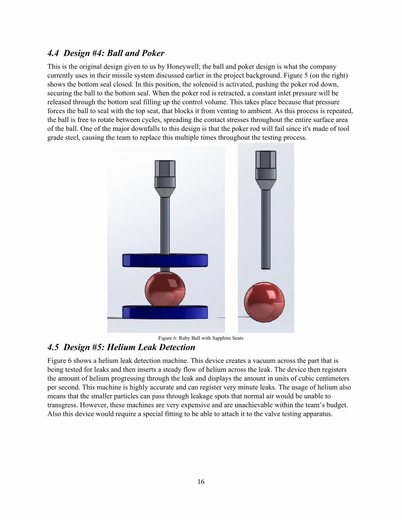
4.4 Design #4: Ball and Poker This is the original design given to us by Honeywell; the ball and poker design is what the company currently uses in their missile system discussed earlier in the project background. Figure 5 (on the right) shows the bottom seal closed. In this position, the solenoid is activated, pushing the poker rod down, securing the ball to the bottom seal. When the poker rod is retracted, a constant inlet pressure will be released through the bottom seal filling up the control volume. This takes place because that pressure forces the ball to seal with the top seat, that blocks it from venting to ambient. As this process is repeated, the ball is free to rotate between cycles, spreading the contact stresses throughout the entire surface area of the ball. One of the major downfalls to this design is that the poker rod will fail since it's made of tool grade steel, causing the team to replace this multiple times throughout the testing process.
Figure 6: Ruby Ball with Sapphire Seats
4.5 Design #5: Helium Leak Detection Figure 6 shows a helium leak detection machine. This device creates a vacuum across the part that is being tested for leaks and then inserts a steady flow of helium across the leak. The device then registers the amount of helium progressing through the leak and displays the amount in units of cubic centimeters per second. This machine is highly accurate and can register very minute leaks. The usage of helium also means that the smaller particles can pass through leakage spots that normal air would be unable to transgress. However, these machines are very expensive and are unachievable within the team’s budget. Also this device would require a special fitting to be able to attach it to the valve testing apparatus.
16
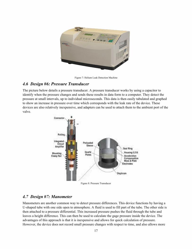
Figure 7: Helium Leak Detection Machine
4.6 Design #6: Pressure Transducer The picture below details a pressure transducer. A pressure transducer works by using a capacitor to identify when the pressure changes and sends these results in data form to a computer. They detect the pressure at small intervals, up to individual microseconds. This data is then easily tabulated and graphed to show an increase in pressure over time which corresponds with the leak rate of the device. These devices are also relatively inexpensive, and adapters can be used to attach them to the ambient port of the valve.
Figure 8: Pressure Transducer
4.7 Design #7: Manometer Manometers are another common way to detect pressure differences. This device functions by having a U-shaped tube with one side open to atmosphere. A fluid is used to fill part of the tube. The other side is then attached to a pressure differential. This increased pressure pushes the fluid through the tube and leaves a height difference. This can then be used to calculate the gage pressure inside the device. The advantages of this approach is that it is inexpensive and allows for quick calculation of pressure. However, the device does not record small pressure changes with respect to time, and also allows more
17

room for human error as the device can be read improperly. This data is also not directly imported to a computer and the team would have to consider the effects of heat on the readings.
Figure 9: Manometer
4.8 Design #8: Synthetic Diamond Poppet Diamond has extreme hardness and wear resistance that makes it ideal to implement it in the pneumatic valve test fixture. Selecting a synthetic diamond poppet design (push rod is connected to ball), as opposed to the suggested poker rod and ruby ball combination, eliminates the need to guide the ball and ultimately minimizes the leakage from the system. One of the major concerns about utilizing a synthetic diamond poppet in the design is that the manufacturing process is very complex. However, the team has been in contact with synthetic diamond distributors that might be able to manufacture the poppet for the testing fixture. Applying such material to the design will allow for room to further challenge the limits and exceed the 10 million cycle requirements.
18

Figure 10: Synthetic Diamond Poppet
4.9 Design #9: Guide Fingers The use of guide fingers in our design will give the ball that is independent of the poker a vertical path to follow from the bottom seat to the top, and vise versa. This will ensure proper contact for a sufficient seal. If the ball has no guide system from one point to another, it can cause one of two possible issues. First, when the push rod retracts, and the ball is traveling from the bottom seat to the top, it may experience deflection in the horizontal plane. This can cause the ball to bounce around before finally being pushed into the seal by the inlet pressure. This brief delay is undesirable, as our device must be cycled multiple times per second and this increases the wear on our ball. The second case is when the ball is being forced to the bottom seat by the push rod. If there is no guide system during this step, the poker can become offcentered, pushing the ball away from the center of the seat, preventing a complete seal. This variance in travel and sealability is undesirable if the design does implement an independent ball system.
19

Figure 11: Guide Fingers
5 DESIGN SELECTED 5.1 Rationale for Design Selection A Decision Matrix (Table 2) was developed in order to facilitate the selection of each subsystem for the final design. The team evaluated different methods for each subsystem coinciding with the customer requirements. Considering all the possibilities, the team ranked each method based on precision, cost, obtainability, reliability, interchangeability, and feasibility. Precision and cost are highly weighed due to the fact that this project does have a limited budget and requires accurate documentation and measurements. Also precision is imperative since each individual component will be small, leaving no room for added error. Along with that, the components of the design must be obtainable with a feasible design. The final design component selection are justified in Table 2. The preliminary design selection test fixture consisted of being actuated with a pulse width modulated solenoid due to the accuracy and reliability of its performance. The original poppet and seat was designed to be a spherical poppet made of one solid material with no external components. The material for the original poppet design was synthetic diamond, because it has overall proven to be the best material. A pressure transducer was going to be utilized for taking pressure measurements throughout testing, and the housing was going to be manufactured out of aluminum due to its beneficial thermal qualities.
20

Table 1: Decision Matrix
5.2 Design Description 5.2.1 Materials : The whole basis for this project is that using different materials for the internals of a pulse width modulation solenoid will increase the lifetime substantially and therefore broaden the spectrum of uses for them. Material selection for the seats, ball and or poppet are pivotal for the success of the project in proving or disproving this theorem. Initially the team was under the impression that these materials had been pre selected with the title of the project ruby ball and sapphire seat endurance test but quickly learned that this was an area where the team still had some design freedom. Honeywell presumes that gemlike materials will extend the lifetime of cycles completed, while simultaneously keeping the cost low enough to be realistic. The team decided to analyze the top two options provided by our decision matrix, which were polycrystalline diamond and corundum. Corundum, also known as aluminum oxide, is the chemical composition of ruby and sapphire. Ruby and sapphire are the same material but differ in the color they take on, which is a key note for this analysis as they will be referred to the same thing. Since ceramics deform differently than the steel they were using in their previous design, we have to analyze the materials differently. Ceramics and gemstones develop cracks that propagate and eventually lead to failure, rather than deforming plastically for a long time. Since this is the case, we are going to review the hardness of each material, the toughness, and recorded impact testing. There are multiple different ways or testing for gemstone hardness but the two scales that will be referred to in this section are the mohs scale of hardness and the materials absolute hardness. Hardness is defined as a material’s resistance to
21

localized scratches or dents [5]. The mohs scale of hardness is more of a qualitative test that relates the hardness of one material to the hardness of another material, which is defined by arbitrary assigned values. Diamond ranks at the top of this scale with a mohs scale of hardness value of 10, and every other value is given based on how they relate to the hardness of diamond. Ruby and Sapphire are both right behind diamond though with a mohs hardness scale rating of 9 [6]. The most important ranking in this scale is 7, because quartz has a mohs scale rating of 7. Since quartz is the most common airborne mineral, the mohs rating must be above 7 to prevent excessive wear due to quartz particles [6]. The issue with the mohs hardness scale though is the values aren’t proportional. Quantitatively speaking the mohs hardness scale doesn’t provide much information other than diamond is better rated than the other material and that our materials won’t degrade to the quartz content in the air. Absolute hardness though is a qualitative way to rate materials based on their hardness. These tests are done in lab settings and assigned a proportional numerical value based on their hardness. Diamond on this scale ranks in at 1500, whereas ruby and sapphire both are given a value of 400 [7]. This means that diamond is 3.75 times harder than both ruby and sapphire, making it far more optimal than both. Based off just these two tests, polycrystalline diamond is the best option for our design if cost allows but we must also consider the fracture toughness. Table 2: Polycrystalline Diamond Fracture Toughness [8]
This section will use tables 2 and 3 to compare the two competing materials fracture toughness to see which can handle the amount of cycling the best. Fracture toughness is a number that was calculated and then referenced in tables that are pre existing. This allows us to determine which material will yield the best results and allow us to see which material gives us the best shot of reaching over 10 million cycles. Based off the tables and calculations, diamond again comes out stronger than ruby/sapphire by a factor larger than 2 [8,9]. Given that synthetic diamond has proven to be more feasible for our application based off the tests above, as long as it can be manufactured and produced at a competitive rate it makes it our best option.
22
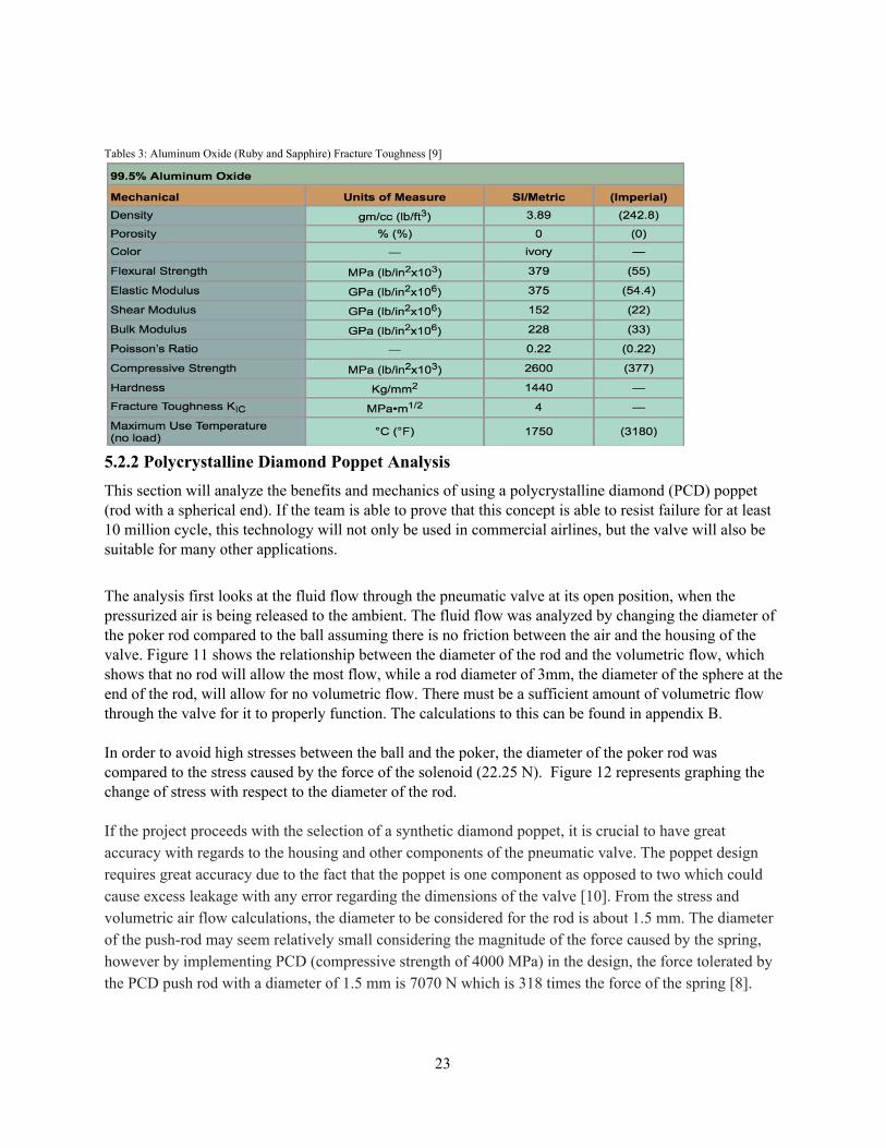
Tables 3: Aluminum Oxide (Ruby and Sapphire) Fracture Toughness [9]
5.2.2 Polycrystalline Diamond Poppet Analysis This section will analyze the benefits and mechanics of using a polycrystalline diamond (PCD) poppet (rod with a spherical end). If the team is able to prove that this concept is able to resist failure for at least 10 million cycle, this technology will not only be used in commercial airlines, but the valve will also be suitable for many other applications.
The analysis first looks at the fluid flow through the pneumatic valve at its open position, when the pressurized air is being released to the ambient. The fluid flow was analyzed by changing the diameter of the poker rod compared to the ball assuming there is no friction between the air and the housing of the valve. Figure 11 shows the relationship between the diameter of the rod and the volumetric flow, which shows that no rod will allow the most flow, while a rod diameter of 3mm, the diameter of the sphere at the end of the rod, will allow for no volumetric flow. There must be a sufficient amount of volumetric flow through the valve for it to properly function. The calculations to this can be found in appendix B. In order to avoid high stresses between the ball and the poker, the diameter of the poker rod was compared to the stress caused by the force of the solenoid (22.25 N). Figure 12 represents graphing the change of stress with respect to the diameter of the rod. If the project proceeds with the selection of a synthetic diamond poppet, it is crucial to have great accuracy with regards to the housing and other components of the pneumatic valve. The poppet design requires great accuracy due to the fact that the poppet is one component as opposed to two which could cause excess leakage with any error regarding the dimensions of the valve [10]. From the stress and volumetric air flow calculations, the diameter to be considered for the rod is about 1.5 mm. The diameter of the push-rod may seem relatively small considering the magnitude of the force caused by the spring, however by implementing PCD (compressive strength of 4000 MPa) in the design, the force tolerated by the PCD push rod with a diameter of 1.5 mm is 7070 N which is 318 times the force of the spring [8].
23
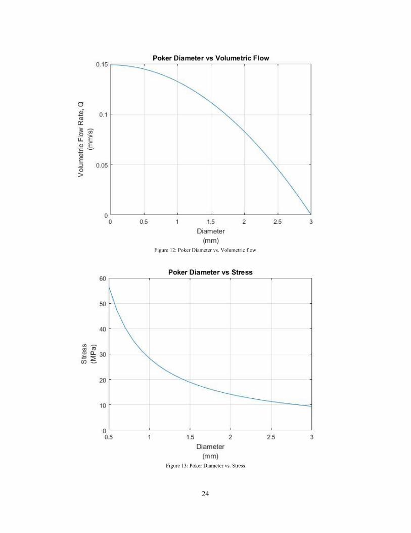
Figure 12: Poker Diameter vs. Volumetric flow
Figure 13: Poker Diameter vs. Stress
24

5.2.3 Pulse Width Modulation Actuation of a Proportional Solenoid In order to achieve linear actuation of the poker arm of the synthetic poppet, a proportional solenoid will be used powered through pulse width modulation (PWM). A proportional solenoid is a type of solenoid that responds linearly to different currents and voltages. A solenoid is a type of electromagnet that exhibits linear actuation when a current is applied to it. The higher the current that runs through a proportional solenoid, the higher the force that can be exhibited by the solenoid’s armature. The higher the voltage potential between solenoid contacts, the bigger the linear actuation of the armature [12]. PWM is a type of digital signal used in many electronic, pneumatic, and sophisticated control applications in order to vary the strength and timing of a signal such as voltage or current. A signal is either “on” or “off;” however, by modulating the amount of time a signal is on or off an average signal can be achieved [13]. A signal’s Duty Cycle is a term that describes how much time a signal is considered “on.” If a signal has a 50% Duty cycle, it is on half of the time, and off the other half. The frequency at which a signal is modulated will have an effect on its signal as well. A higher frequency of modulation will result in a more blended signal, while a low frequency will result in a rigid transition between on and off signals. By using a proportional solenoid powered through PWM technology using Arduino, linear actuation of the pneumatic valve can be programmed to certain design constraints. A requirement from Honeywell was to be able to cycle the valve for 10 million cycles no faster than 10 Hz. Although a suggested stroke of 0.015 inches was given, the stroke will depend on the diameter of the poppet if the team chooses to pursue that pressure sealing design [12]. Proportional solenoids are manufactured in different sizes that respond to different currents and voltages and outputs linear actuations of varying stroke. Shown below in Figure 13 is a proportional solenoid that satisfies the design requirements for the valve:
Figure 14: TLX Proportional Solenoid Actuator
This proportional solenoid manufactured by TLX Technologies has a maximum stroke of 0.130 in and can provide a force up to nine pounds. In order to provide the two – five pounds of downward force on the poppet, the solenoid will be powered at 0.5 A in order to generate a three-pound force, as shown
25

below in Figure 14:
Figure 15: Force vs. Stroke Curve
This proportional solenoid can be cycled at frequencies up to 500 Hz, 50 times the maximum frequency required by Honeywell for testing [14]. The hysteresis induced from the exerted force on the solenoid arm is less than 5%, which makes for a reliable solenoid to provide appropriate upward and downward force to the ball or poppet. The quick response time of 200 microseconds makes this solenoid extremely useful for high-speed applications, such as actuating the pneumatic valve [15]. 5.2.4 Contact Angles/Sealing methods One of the main requirements of this project is to regulate and measure the amount of leakage the device releases during operation. In order to ensure desirable leakage quantities, proper air pressure sealing is required. The proper contact surface, radius, depth, other characteristics are all contributing factors in leakage magnitude. There are many contact surface types like flat, chamfers, rounded, conical, etc., all of which have distinct strengths and weaknesses. A flat seat simply seals inlet pressure using the contact between the ball and a square edge for a seat. Flat seats offer a quick and simple solution, and their small contact surface area makes for highly concentrated loads, resulting in a strong seal. These characteristics also result in high levels of stress along this small contact area. Considering the extensive testing this project requires, small imperfections will eventually accumulate along the contact surface, gradually reduce the efficiency of our seal. Conical seats offer a self-centering feature as the poppet is inserted into the seat. This eliminates the need for a guiding system within the device. Unfortunately the sealing properties of these seats is questionable, and the range of different possible failures is vast. Rounded seats on the other hand, provide what seems to be the best possible seal. Rounded seats that match the radius of the ball provide what seems to be the strongest possible seal. When the poppet is forced against the seat, a relatively large contact area is formed. This large surface allows for forces to be distributed throughout the entire area, lowering contact stresses. Although this helps prevent erosion to the ball and seat, this design is robust enough to handle small imperfections that may occur on the surface, while still maintaining a sufficient seal. When observing the average seat design, even the smallest surface damage on the point of contact can provide a direct path for air to escape. A small cavity somewhere on the surface of a rounded seat is not enough to allow air to leak across the entire area of the seat.
26
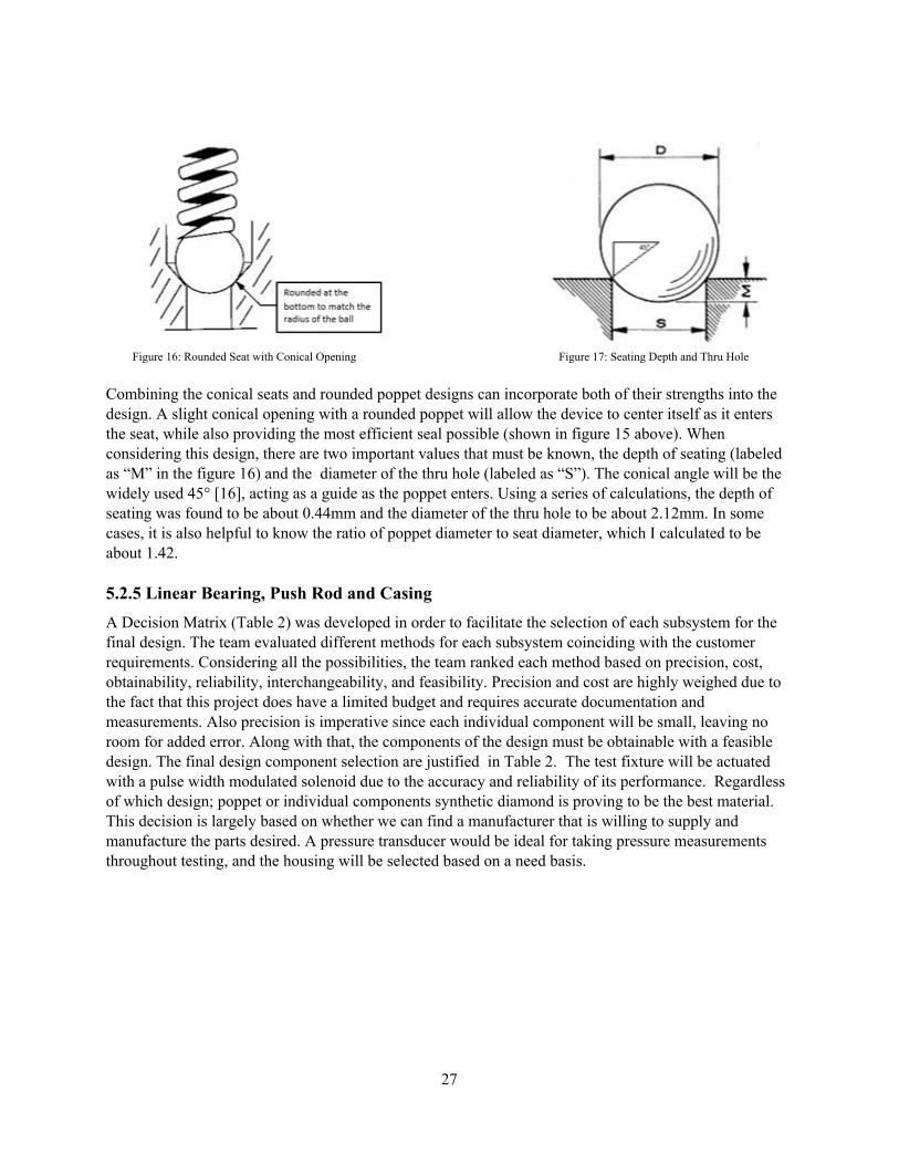
Figure 16: Rounded Seat with Conical Opening Figure 17: Seating Depth and Thru Hole Combining the conical seats and rounded poppet designs can incorporate both of their strengths into the design. A slight conical opening with a rounded poppet will allow the device to center itself as it enters the seat, while also providing the most efficient seal possible (shown in figure 15 above). When considering this design, there are two important values that must be known, the depth of seating (labeled as “M” in the figure 16) and the diameter of the thru hole (labeled as “S”). The conical angle will be the widely used 45° [16], acting as a guide as the poppet enters. Using a series of calculations, the depth of seating was found to be about 0.44mm and the diameter of the thru hole to be about 2.12mm. In some cases, it is also helpful to know the ratio of poppet diameter to seat diameter, which I calculated to be about 1.42. 5.2.5 Linear Bearing, Push Rod and Casing A Decision Matrix (Table 2) was developed in order to facilitate the selection of each subsystem for the final design. The team evaluated different methods for each subsystem coinciding with the customer requirements. Considering all the possibilities, the team ranked each method based on precision, cost, obtainability, reliability, interchangeability, and feasibility. Precision and cost are highly weighed due to the fact that this project does have a limited budget and requires accurate documentation and measurements. Also precision is imperative since each individual component will be small, leaving no room for added error. Along with that, the components of the design must be obtainable with a feasible design. The final design component selection are justified in Table 2. The test fixture will be actuated with a pulse width modulated solenoid due to the accuracy and reliability of its performance. Regardless of which design; poppet or individual components synthetic diamond is proving to be the best material. This decision is largely based on whether we can find a manufacturer that is willing to supply and manufacture the parts desired. A pressure transducer would be ideal for taking pressure measurements throughout testing, and the housing will be selected based on a need basis.
27

Figure 18: Housing Design with outer dimensions, in inches
A guide system will be implemented if the team decides to use an actual ball and poker for our seal. The guides will prevent the ball from getting stuck, creating extra force on the poker, and bouncing around, causing unnecessary wear on the ball. The design being considered is a guide consisting of fingers that will control the path of the ball. The material will be Teflon (PTFE).Teflon is being considered because it is a well-known material for heat resistance and low friction coefficients. According to DuPont, the material is able to withstand temperatures up to 600°F [18]. Teflon has a low friction coefficient of 0.10 [18]. The finger design consists of different cylindrical rods positioned around the ball to create a guide.
Figure 19: Finger Guide Design
As shown above in the figure, the finger design will consist of three cylindrical rods equidistantly spaced around the ball to guide it. The three fingers offer the minimum amount of guidance required with the least amount of contact, and allows for the air to still flow through the chamber. These rods only need to be the length between the seats. They will be subjected mainly to a frictional force, with a small contact area. To calculate the frictional force that will occur, the system will be calculated using a steel ball. To calculate the frictional force, we will calculate the contact area upon which the force is applied. The coefficient of friction is very low for this system, at 0.10 [18]. The maximum contact stress that can occur would be at about 5 lbf. The contact stress is calculated with [19]. In this equation, F is the force, which a force from the spring of 5lbs was used. The area, a is multiplied by 3 for the number of fingers. The area is calculated by [19]. The F used here is 5 lbf. Poisson’s ratio, v1 and v2 are equal to 0.30 and 0.46 respectively [17,18]. E1 and E2 are the Young’s Modulus values, equaling 30*106 psi and 4000 psi [18,19]. The Radii, denoted as r1 and r2, are equal to 0.059in and 0.03937in. The calculated contact stress σcontact, is equal to 2853 psi. Comparing this to the tensile strength of Teflon, which is equal to 4600 psi [18], we calculate a factor of safety is equal to 1.61. This is a good safety factor because the 5 lb-force is the
28

highest possible force the ball will experience, and the force from the poker rod will not all be applied to the guide fingers from the ball. 5.2.6 Pressurizing and Leakage Honeywell has asked us to actuate this valve through a set amount of cycles. Throughout this process and afterwards, we need to measure the amount of leakage that is occurring. This data will be the end product of the project. In order to collect this data, we need a method of measuring the amount of leakage that occurs. This includes ensuring that the device will be able to connect to the valve, keeping it within the project’s budget, and selecting an accurate enough method. One of the simplest methods to measure leakage is to submerge the outlet under water and count the number of bubbles that appear. The average volume of an air bubble under water is 40 mm3, which at a rate of one bubble per minute converts to a leak rate of 30 mm3/sec. This method would be cheap and simple to implement, however, it may not be as accurate as other methods. Based on these considerations, the device will use a temperature gauge and a pressure transducer to measure leakage. The results from individual analysis show that with the dimensions of the valve, changing the temperature by 10°F changes the pressure by .006 MPA (0.87 psi). A temperature gauge also provides a separate set of data to give to Honeywell. Both of these devices can be fitted to the valve without interfering with each other. The results from these two methods can be compared for multiple readings. Purchasing both gauges remains well within the project budget. 6 PROPOSED DESIGN 6.1 Design Implementation During the fall semester the team created a proof of concept, a 3-D printed model of the valve was made at the Cline Library MakerLab. The prototype had to be printed in four different components. The housing is constructed in two separate pieces, allowing for the seals to be press-fitted. The housing also has an exposed part covered by plexiglass so the actuation can be seen. The scale of the valve will be upsized, and we will also use different PLA filament colors to better differentiate the components within the valve.
6.2 Resources Resources used to execute this design include NAU faculty members, David Trevas and Sarah Omen. US synthetics will hopefully be supplying the team with synthetic polycrystalline diamond material and manufacturing. Our client, Honeywell has also been a helpful source of information. SLX Technologies was most likely supply the proportional solenoid for valve actuation using Arduino software. 6.3 Materials The preliminary Bill of Materials (BOM) is shown below in Table 5. The materials for the project included a PWM solenoid actuator, synthetic polycrystalline diamond poppet, seats and pushrod, metal casing, and PLA (polylactic acid) bioplastic for the 3D printed prototype.
29

Table 5: Preliminary Bill of Materials (BOM)
6.4 Budget Check The team had found a sponsor that is willing to provide the seats and the poppet valve, along with the manufacturing of these items for free. Having our largest projected cost covered without touching any of our budget allows us to get better quality products for everything else, and invest in other things like rapid prototyping. Cline Library charges $0.10 per gram for 3D printing, so prototyping will be extremely cheap and easy. So far, the largest expense that will touch the budget is the purchase of a solenoid actuator, and an Arduino type hardware to run PWM on. Both of these items cost about $30-50, which is well within our budget. Staying within our $2000 budget will not be a challenge for this project.
6.5 Assembly View Figure 19, below, shows an exploded view of the preliminary assembly for the pneumatic valve that was decided upon during the fall semester. Though, many changes have been made through the course of the the spring semester, Section 7 discusses the design changes in detail. This assembly only includes the housing seat and poppet (1-3 on from the BOM).
30

Figure 20: Preliminary Design Selection
31

7 IMPLEMENTATION 7.1 Design of Experiments In Appendix B, Table B1 shows a list of the completed and final Bill of Materials (BOM) which includes everything needed to assemble the test fixture. Due to the complexity of machining diamond, US Synthetic will be manufacturing and machining the seat and both a hemispherical and chamfered poppet. The PCD material and machining of the material will be free of charge. The most time consuming and costly components within the BOM is the machining of the housing and armature which will be done by Xometry. A majority of the the resources purchased for the assembly will be purchased from McMaster-Carr which is listed in the bill of materials. The team has also purchase a solenoid and springs for the solenoid. Since the life of the springs are much lower than the span of the testing procedure the team purchased 40 springs to replace the current spring when the elasticity wears out and no longer provides the required 5 pounds of force. An Arduino has been purchased along with the circuit components required to actuate the solenoid. A camera monitoring system has also been purchased in order to view the testing apparatus at any time of the day using a smartphone application. The camera will also be used to record when failure has occurred. The pressure transducer and converter selected to track the air leakage were purchased through Valworx.
The team has submitted a purchase request and currently waiting for the arrival of the parts in order to start assembling the test fixture. The testing procedure will begin immediately after receiving everything listed in the bill of materials. Figure 20 shows a list of all the important dates and deadlines the team must meet during the Spring Semester. As shown, the testing and data analysis must be completed by April 28th, 2017 in order to present at Undergraduate Symposium.
Figure 21: List of Deadlines
7.2 Design of Experiments A design of experiments was run in order to determine how to reduce any large temperatures on the Arduino. The two variables used for this testing were the amount of duty cycle on the solenoid, as well as two different types of transistor components. The two different transistor being considered are a MOSFET and a TIP120. The Design of Experiments is shown in Figure 21 below. The ß were determined through the use of Excel, but the equation that they derive cannot be created because there are no numbers to associate with the two types of transistors. However, this data has shown that in order to reduce temperature the most, the Arduino should function at 25% duty cycle as well as use the TIP120 transistor.The reason for this is that having a smaller duty cycle means that the device will be actuated less. Also, the TIP120 has a larger surface area including an extruding metal surface which acts as a cooling fin for the component.
32

Figure 22: Design of Experiments
7.3 Design Changes Throughout this semester the team has held multiple meetings with the capstone sponsor and the synthetic diamond distributor to come to a finalized design. Initially the team was under the impression that the PCD was being provided for the initial testing with the hope of a business proposition opening up. Eventually, it was agreed upon that a face to face meeting with all parties present would be best to move the design into production and to refine the details. U.S Synthetic flew three correspondents out to Tempe and Honeywell had multiple people involved with pneumatics attend the meeting. Although the meeting went well, and the team won’t have to pay for the multiple components that U.S Synthetic is providing, the design changed dramatically. These changes that the team has worked to implement will be explained in full detail in the given sections.
33
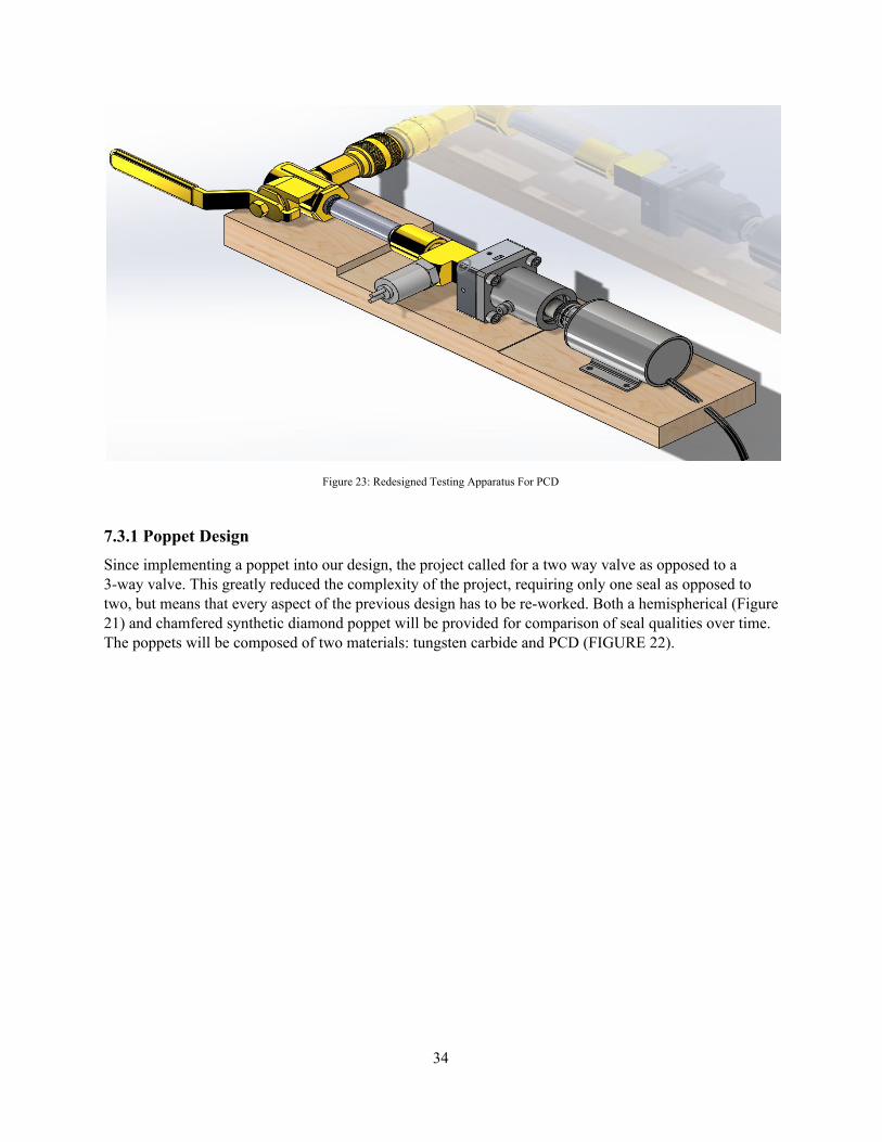
Figure 23: Redesigned Testing Apparatus For PCD
7.3.1 Poppet Design Since implementing a poppet into our design, the project called for a two way valve as opposed to a 3-way valve. This greatly reduced the complexity of the project, requiring only one seal as opposed to two, but means that every aspect of the previous design has to be re-worked. Both a hemispherical (Figure 21) and chamfered synthetic diamond poppet will be provided for comparison of seal qualities over time. The poppets will be composed of two materials: tungsten carbide and PCD (FIGURE 22).
34

Figure 24: Hemispherical Polycrystalline Diamond and Tungsten Carbide Poppet
Figure 25: Chamfered Polycrystalline Diamond and Tungsten Carbide Poppet
35

Since the team is receiving two potential solutions, we had to design a universal poker valve that can not only hold both poppets but also can attach to the clevis fitting on the solenoid. Instead of machining holes through each poppet and increasing the manufacturing costs for U.S Synthetic, the team designed a poker rod that would allow each poppet to fit inside and be attached with the use of four set screws. This design change allows for the poker rod to become more rigid and takes the failure mode previously experienced out. The team will do preliminary testing with light loading to determine which poppet design will be optimum to begin the first trial with. If the poppet fails throughout testing, the team will switch to the other design for the remaining time. Given the time and budget constraints the team doesn’t have a way to feasibly test both designs in unison.
7.3.2 Housing Since the components and number of seats that the team is being provided has changed, we had to redesign the housing to accommodate for these needs. The housing is still round in geometry, supporting linearity of the design. A linear bearing is also being attached to the top of device with four screws to guide the pushrod, but not to overconstrain it from self centering when engaged. The poppet is to be inserted into a cavity at the end of the push rod which matches the dimensions of the poppet itself. It will be secured will glue between the contact surfaces of the poppet and push rod, as well as four set screws that are inserted through the push rod to better fasten the poppet in place. Similarly, the seats will be glued and fastened with set screws inside the housing. The clevis fitting mentioned earlier, should allow for a small degree of freedom, allowing the conical shape of the seat to self align the poppet as it is inserted. Below the seal is a control volume that is to be sealed off mid-test, while the seal remains closes, to allow the pressure transducer to record the amount of leakage escaping through the system. This volume has been designed to be completely adjustable depending on the testing requirements as discussed in the Test Parameters below.
Figure 26: Redesigned Poppet Arm and Single Seat Valve
36

7.3.3 Test Parameters
Testing procedures of this experiment must be held constant throughout all 10 million cycles in order to provide reliable results. This 10 million cycles will take well over 11 days of testing non-stop all day and night. During these 11 days, two measurements of leakage must be taken every day. This will provide 24 data points that represent the amount of leakage that escapes through the poppet from a control volume sealed from the ball valve. Weather or not these results show any leakage is irrelevant. What the purpose of this test is to observe any increases in leakage due to destructive wear on the sealing components due to fatigue over time. The team has purchased a camera to monitor the testing equipment while the apparatus is operating when no one is watching it. This will allow us to do failure analysis if one of the components fails during the night. 7.3.4 Leak Down Test Since the team now only has to focus on the sealing properties of one seat, we shifted our focus to performing precise leak down tests. This test consists of a pressure transducer attached to a control volume that is located before the inlet seat. The team will engage the poppet to provide a seal while providing the inlet pressure of 50 psi. Once the team has locked the poppet engaged into the seat, the ball valve that is located below the control volume will be closed, trapping the 50 psi inside (provided the components seal perfectly). Any leakage or leak rate is fine, as long as it stays consistent throughout the cycling. The pressure transducer allows us to use a data logger on our arduino board to take accurate measurements for a precise amount of time. Having this information stored will also help the team later when this data has to be translated and graphed vs completed cycles. As stated above, the issue with this design and the leak down test in general is the control volume has to be the correct size to provide results that can be interpreted. In Order to account for this though the team has built a control volume that is based off no leakage, but can be modified with extra pipe to continuously provide results no matter what leakage we will experience throughout this experiment. This test will consist of closing a valve below the test fixture in the pressure line while the poppet is held down. This will create a pressurized controlled volume below the sealing area. A pressure transducer will be connected to this volume to identify any leakage, as the pressure will force air through any gaps at the poppet. This device operates through the use of a strain gauge that flexes and changes the geometry of a capacitor to provide a signal whenever the gauge moves with the pressure changes. The pressure transducer outputs signals in volts, so it will be connected to a voltmeter. The voltmeter will be connected to a National Instruments cDAQ-9174 module, a PCI data acquisition card, and two additional modules, the NI-9221 and the NI-9201. The NI-9201 creates a connection between the signal source, the voltmeter, and the data acquisition system. The data acquisition card converts an analog signal to a digital one which can be read by the computer through a USB cable. This setup allows for the voltmeter to send data to a computer. There it is analyzed by a program called LabVIEW, which creates and runs virtual instruments. The program will be able to read the small changes in output voltage and output it as an Excel file. The virtual instrument can be configured to provide a set number of samples at a set rate per time. The test will run for five minutes, in which time the computer will collect a data point every 10 milliseconds. This data can be analyzed to determine the pressure difference, and the rate at which it changes. Using the set control volume and the pressure difference, an average leak rate in terms of cubic centimeters per second can be calculated. Once all 23 data points have been collected, a plot will be made showing any changes in leak rate over the course of the testing. All of the equipment required to run this test past the pressure transducer will be supplied by the thermofluids lab in the Northern Arizona University Engineering
37
Building.
8 TESTING As discussed earlier in Chapter 1, the requirements of this project are to create a device to cycle a valve through 10 million cycles. In addition, this test must prove whether a gem like material can survive the wear of this test while maintaining consistent leak rates. The team accomplished this task by cycling a valve with a solenoid using a PCD seat and poppet. The material did indeed survive the extensive trial without any visible wear. Further, testing procedures used enabled the team to prove that the leakage did not increase throughout the test.
8.1 Apparatus Testing Procedures The procedures taken to operate the apparatus, and record results is list for future test replication.
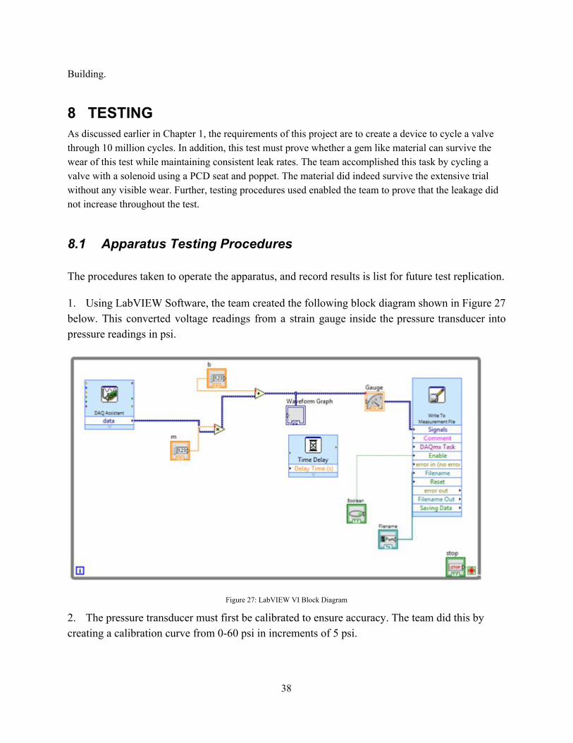
1. Using LabVIEW Software, the team created the following block diagram shown in Figure 27 below. This converted voltage readings from a strain gauge inside the pressure transducer into pressure readings in psi.
Figure 27: LabVIEW VI Block Diagram
2. The pressure transducer must first be calibrated to ensure accuracy. The team did this by creating a calibration curve from 0-60 psi in increments of 5 psi.
38

3. Shut off inlet air.
4. Turn off solenoid and record the time. Recording the time the device is turned off and on, allows the team to track cycles.
5. Disconnect hose from device and reattach to 60-gallon control volume tank.
6. Pressurize tank to slightly above 10 psi and then close tank valve.
7. Disconnect hose from generator and reattach to device. The hose will now transfer air flow from the control volume to the PCD seal once tank valve is opened.
8. Start running the VI.
9. Open control volume tank valve, releasing air into hose.
10. Activate stopwatch once pressure reads 10 psi
11. Stop VI once stopwatch reaches 3 minutes and save file.
12. Export data into excel.
13. Use excel to calculate pressure loss.
14. Turn the solenoid on again and record the time.
15. Turn on inlet air back on to cool device.
16. Log data with its corresponding number of cycle.
8.2 Testing Results The results from the leakdown test are shown in Figure 28, where leakage is plotted against number of cycles. While the data may seem scattered, the amount of leakage that escaped from the system consistently resided between 1%-2% pressure loss per minute. This trend continued beyond 10 million cycles, thus implying a successful testing process with no compromises to the air seal.
39

Figure 28: Plot of Leakage vs. Cycles
9 CONCLUSIONS
9.1 Contributors to Project Success At the beginning of the project, the team formulated a Team Charter in order to establish official guidelines, the team will follow in order to remain a successful team, and everyone understands what they are held accountable for. Measures have been taken to remain within the parameters of the Purpose and Goals stated in the Team Charter. Coping strategies stated in the Ground Rules of the Team Charter were made to plan for stress amongst individuals, as well as any feuds that may arise between teammates. These Ground Rules were followed admirably. The group performed as a functional team, even though the most stressful days.
The most positive/negative aspects of this project vary. The sole contributor to the project’s success is the aid the team sought out from others. First, the project wouldn’t have been possible without our sponsor, Honeywell. They assigned the capstone project, funded the team, and provided guidance and feedback on a weekly basis. Second, the PCD material used to achieve the project’s goal was provided by US Synthetic. This connection however would have never been made without Dr. Trevas, who was a tremendous help to the team every step of the way. Lastly, each individual of the team pulled together to overcome this project together. The most negative aspect of this project was timing. The design had so many changes that the team was left waiting until the end of the semester for parts to arrive. This caused time constraints, due to the eleven day testing period.
40

Throughout the project, the team experienced several challenges that had to be concurred. The design has undergone countless changes due to newly discovered difficulties, both before and after ordering parts. The method of oscillation, sealing, measuring, pressurizing, material selection, and many other aspects of the design had to be altered along the way. Besides design changes, the team also encountered problems during testing. The air supply was shut off at one point, causing the device to overheat and seize up, and once it even vibrated off the table, crashing into the ground. Luckily, neither of these incidents rendered the device inoperable.
9.2 Opportunities/areas for improvement This project was a great learning tool that allowed each of the team members to grasp experience on the engineering industry. There were many obstacles that the team faced during the testing process. The obstacles that the team faced ranged from late parts, as well as miscommunication from the venders which shortened test time. This could have been avoided with better time management, and the quality of the test could have been improved. With more time the team would have like to repeat this using the chamfered poppet to compare results, and potentially have test a steel set of similar parts to have on hand the data that they do degrade in the test fixture that we built. The scattered results can also be improved by implementing a more precise methods of sealing the valve. One of which, is a process called lapping. this is where both the poppet and seat are made together, so that they mate together perfectly.
10 REFERENCES [1]"Mechanical Actuators." : Linear Motion Control. N.p., 2016. Web. 30 Sept. 2016.
[2]"Pneumatic Valve Actuator." Vacuum 23.10 (1973): 374. Web.
[3]I. Studios, "Hydraulic Valve Actuators for Valve Control and Valve Automation Solutions", Aberdeendynamics.com, 2016. [Online]. Available: http://www.aberdeendynamics.com/remote_valve.php. [Accessed: 01- Oct- 2016]. [4] "Proportional Solenoids and Valves – TLX Technologies – TLX Technologies", TLX Technologies, 2016. [Online]. Available: http://www.tlxtech.com/solenoids/proportional-solenoids. [Accessed: 29- Oct- 2016]. [5] The Editors of Encyclopedia Britannica. (2007, November 11). Mohs Hardness. [Online]. Available: https://www.britannica.com/science/Mohs-hardness [6] Gem Rock Auctions. (2012, February 26). Mohs Scale of Hardness. [Online]. Available:https://www.gemrockauctions.com/learn/technical-information-on-gemstones/mohs-hardness-scale-for-gemstones [7] GemSelect.com. (2006, September 16). Gemstone Hardness. [Online]. Available: http://www.gemselect.com/gem-info/gem-hardness-info.php [8] "Polycrystalline Diamond (PCD)", Almax-easylab.com, 2016. [Online]. Available: http://www.almax-easylab.com/PCD.aspx. [Accessed: 24- Nov- 2016]. [9] M. Adams. (2013). Aluminum Oxide, Al2O3 Ceramic Properties. [Online]. Available: http://accuratus.com/alumox.html [10] Sumadi Jien, Shinichi Hirai, Kenshin Honda, "Miniaturized Unconstrained on– off Pneumatic Poppet Valve—Experiment and Simulation", Mechatronics IEEE/ASME Transactions on, vol. 14, pp. 626-635, 2009, ISSN 1083-4435. [11] "Polycrystalline Diamond (PCD)", Almax-easylab.com, 2016. [Online]. Available:
41

http://www.almax-easylab.com/PCD.aspx. [Accessed: 24- Nov- 2016]. [12] Honeywell, " Honeywell Aerospace: Ruby Ball and Sapphire Seat Endurance Test Project," Flagstaff, AZ, 2016. [13] "Pulse-width Modulation - learn.sparkfun.com", Learn.sparkfun.com, 2016. [Online]. Available: https://learn.sparkfun.com/tutorials/pulse-width-modulation. [Accessed: 13- Nov- 2016]. [14] "Proportional Solenoid Actuator – TLX Technologies – TLX Technologies", TLX Technologies, 2016. [Online]. Available: http://www.tlxtech.com/solenoids/proportional-solenoid-actuator. [Accessed: 13- Nov- 2016]. [15] 2016. [Online]. Available: http://www.axiomatic.com/pwm-proportional-driver. [Accessed: 14- Nov- 2016]. [16]"Bal-tec - Ball Check Valves", Precisionballs.com, 2016. [Online]. Available: https://www.precisionballs.com/ball_valve.php. [Accessed: 19- Nov- 2016]. [17] APA (6th ed.) Budynas, R. G., Nisbett, J. K., & Shigley, J. E. (2011). Shigley's mechanical engineering design. New York: McGraw-Hill. [18] “Teflon PTFE Flouropolymer Resin”, 2016. [Online]. Available: http://www.rjchase.com/ptfe_handbook.pdf. [Accessed: 19- Nov- 2016]. [19] “Contact Stress Two Spheres in Contact Equations”, 2016 [Online]. Available: http://www.engineersedge.com/material_science/contact-stress-ball.htm.[Accessed: 19- Nov- 2016]. APPENDIX A: House of Quality [20]"Discharge coefficient", En.wikipedia.org, 2016. [Online]. Available: https://en.wikipedia.org/wiki/Discharge_coefficient. [Accessed: 19- Nov- 2016]. [21]"Hydraulic ball valve - MATLAB", Mathworks.com, 2016. [Online]. Available: https://www.mathworks.com/help/physmod/hydro/ref/ballvalve.html?requestedDomain=www.mathworks.com. [Accessed: 19- Nov- 2016]. [22]"Design, Care and Feeding of Check Valves - IBLS", Ibls.org, 2016. [Online]. Available: http://ibls.org/mediawiki/index.php?title=Design,_Care_and_Feeding_of_Check_Valves. [Accessed: 19- Nov- 2016].
42

APPENDIX A - House of Quality
43
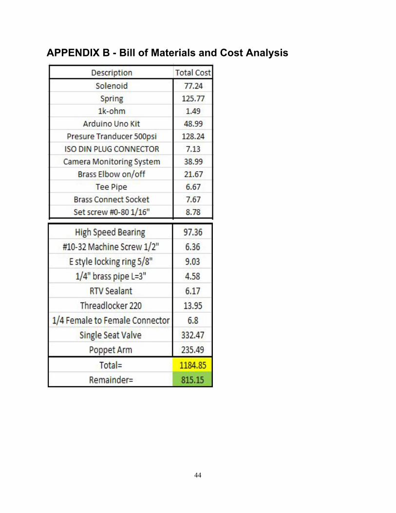
APPENDIX B - Bill of Materials and Cost Analysis
44