honeywell touchpoint pro component specifications - · pdf filetouchpoint pro central...
TRANSCRIPT

Touchpoint ProCentral Controller with User Interface
Specifications
Display Module and User Interface
Part Number TPPR-V-0852
Description Front panel User Interface Assembly
Supply Voltage 24 Vdc (18-32 Vdc)
Power Consumption Maximum 13 W
Power Dissipation Maximum 16 W
Ring Communication Physical layer Isolated RS485
Ring Network Cable 2 x 2 x 1 mm2 twisted pair cable
Relay Outputs 2 x System State Relays
Relay Contacts Min. 12 Vdc, 10 mA
Max. 5 A at 250 Vac / 30 Vdc (non-inductive)
Interfaces 5.7 inch, 320x240 pixels (QVGA), Touch Screen LCD
LED and Button Panel with LEDs for Power, Alarm and Fault indication. Buttons for Accept and Reset functions
Buzzer for audio indication of Alarm/Faults (Sound Level: 85 dB at 100 mm)
10/100 Mbps Ethernet Interface with standard RJ-45 connector
Standard SD Card Interface up to 32 GB. Supports SD cards with form factor of 24 mm x 32 mm x 2.1 mm
2 x RS-485 Modbus connections supporting maximum 115.2 kbps
Panel Dimension 483 mm x 222 mm
Retention of Real Time Clock 24 hours unpowered
Control Module and User Interface
Environmental
Operating Temperature -20°C to +55°C
Storage conditions -20°C to +55°C
Operating Humidity 10% to 90% RH (non-condensing)
Environmental Protection Class Pollution Degree 2 (indoor sheltered)
Maximum Altitude 2000 m
Environmental
Input Supply
Input Voltage 18-32 Vdc (24 Vdc nominal)
Allowable DC Input Voltage Ripple 50 mVp-p (maximum)
Input Supply

Touchpoint ProInput/Output Modules
Specifications
Common Specifications
Dimensions 35.0 mm x 99.5 mm x 114.5 mm (W x H x D)
Installation 5, 7, 9 or 10-way Communication / Power Rail
Maximum Wire Size 2.5 mm2
IP Rating IP20
EMC EN 50270
Power Supply 18-32 Vdc (24 Vdc nominal)
DIN Rail Compatibility TS-35 / 15
Casing Material Polyamide PA 6.6 V0 (UL94)
Operating Temperature Range -40°C to 65°C
Storage Conditions -40°C to 65°C
Operating Humidity Range 10 to 90% RH (non-condensing)
Weight 210 g
Environmental Protection Class Pollution Degree 2 (indoor sheltered)
Analogue Input Module mA
Description 4-channel 4-20 mA Analogue Input Module with 2 or 3 wire interface to detector
Sensor Configuration 4 x 2-wire or 3-wire (current sourced from detector)
Signal Measurement Range 0-25 mA
Supply Voltage (Vs) 24 Vdc (18-32 Vdc)
Field Device Supply Voltage Supply Voltage (Vs) – 0.7 V
Single Channel Field Device Supply Current
Maximum 1 A
Total Field Device Supply Current Total Maximum current : 2 A at 65 °C ambient Total Maximum current : 4 A at 55 °C ambient
Power Consumption 0.8 W (Excluding sensor supply)
Power Dissipation Maximum 3.7 W, at 4 A total field device load Maximum 2.1 W, at 2 A total field device load
Sense Resistance 101 Ω
Connector Coding Analogue Input Module connectors (TB1-TB4) are coded with coding keys to avoid mis-wiring
DIN Rail connector (Module Supply and Communication)
Maximum Current: 4.04 A (18-32 Vdc)
Common Specifications
Analogue Input Module mA

Touchpoint ProInput/Output Modules
Specifications continued
Terminal Identification Label Channel Field Device
1 +V
Input 1
+24 Vdc
2 SIG 4-20 mA signal
3 -V 0 Vdc
4 +V
Input 2
+24 Vdc
5 SIG 4-20 mA signal
6 -V 0 Vdc
7 +V
Input 3
+24 Vdc
8 SIG 4-20 mA signal
9 -V 0 Vdc
10 +V
Input 4
+24 Vdc
11 SIG 4-20 mA signal
12 -V 0 Vdc
+V
3 Wire Detector Touchpoint Pro
+24 Vdc
4-20 mA SIG
-V 101 Ω
0 Vdc
Three wire device
+ +V
2 Wire Detector Touchpoint Pro
+24 Vdc
4-20 mA SIG
-V 101 Ω
0 Vdc
Two wire loop powered device
+V
2 Wire DetectorBarrier
Touchpoint Pro
+24 Vdc
4-20 mA SIG
-V101 Ω
0 Vdc
Two wire device with a barrier
Touchpoint ProInput/Output Modules
Specifications continued
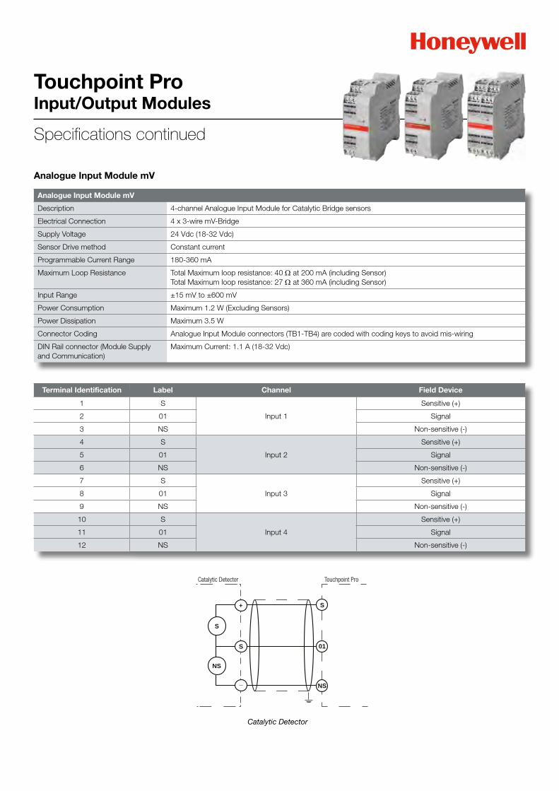
Analogue Input Module mV
Description 4-channel Analogue Input Module for Catalytic Bridge sensors
Electrical Connection 4 x 3-wire mV-Bridge
Supply Voltage 24 Vdc (18-32 Vdc)
Sensor Drive method Constant current
Programmable Current Range 180-360 mA
Maximum Loop Resistance Total Maximum loop resistance: 40 Ω at 200 mA (including Sensor) Total Maximum loop resistance: 27 Ω at 360 mA (including Sensor)
Input Range ±15 mV to ±600 mV
Power Consumption Maximum 1.2 W (Excluding Sensors)
Power Dissipation Maximum 3.5 W
Connector Coding Analogue Input Module connectors (TB1-TB4) are coded with coding keys to avoid mis-wiring
DIN Rail connector (Module Supply and Communication)
Maximum Current: 1.1 A (18-32 Vdc)
Analogue Input Module mV
Terminal Identification Label Channel Field Device
1 S
Input 1
Sensitive (+)
2 01 Signal
3 NS Non-sensitive (-)
4 S
Input 2
Sensitive (+)
5 01 Signal
6 NS Non-sensitive (-)
7 S
Input 3
Sensitive (+)
8 01 Signal
9 NS Non-sensitive (-)
10 S
Input 4
Sensitive (+)
11 01 Signal
12 NS Non-sensitive (-)
S
S
01S
+
_
NS
NS
Catalytic Detector Touchpoint Pro
Catalytic Detector

Digital Input Module
Description 4-Channel Digital Input Module for switched input devices
Electrical Connection 4 x 2-wire Switch Inputs
Supply Voltage 24 Vdc (18-32 Vdc)
Power Consumption 1 W maximum (no inputs connected)
Power Dissipation 2.8 W maximum
Field Terminals (TB1-TB4) Ratings Maximum current of 14 mA through switched input device at 18-32 Vdc
EOL (End Of Line) Resistance 10 kΩ, 0.25 W, ±1%
INL (In-Line) Resistance 2.7 kΩ, 0.25 W, ±1%
Switch Input Device supply Voltage (Vs)
Minimum 15 V Maximum 32 V
Switch Input Device supply Current (Is)
Minimum 5 mA for Supervised OC/SC Switch ON condition Maximum 14 mA for Unsupervised Switch ON condition
Connector Coding Digital Input Module connectors (TB1-TB4) are coded with coding keys to avoid mis-wiring
DIN Rail connector (Module Supply and Communication)
Maximum Current: 95 mA (18-32 Vdc)
Digital Input Module
Touchpoint ProInput/Output Modules
Specifications continued
Terminal Identification Label Channel
1 +
Input 12
3 -
4 +
Input 25
6 -
7 +
Input 38
9 -
10 +
Input 411
12 -
TPPR
SWITCH
+24 Vdc
1 KΩ
75 Ω
0 Vdc
-
TPPR
SWITCH
+24 Vdc
10 KΩ
REOL
1 KΩ
75 Ω
0 Vdc
+
-
TPPR
SWITCH
+24 Vdc
10 KΩ
2.7 KΩREOL
RINL
1 KΩ
75 Ω
0 Vdc
+
-
Unsupervised configuration Supervised for opencircuit configuration
Supervised for open and short circuit configuration
Relay Output Module
Touchpoint ProInput/Output Modules
Specifications continued
Terminal Identification Label Channel
1 NO
Relay 12 NC
3 C
4 NO
Relay 25 NC
6 C
7 NO
Relay 38 NC
9 C
10 NO
Relay 411 NC
12 C
13
V Aux 114 +V
15 -V
16
V Aux 217 +V
18 -V
19
V Aux 320 +V
21 -V
22
V Aux 423 +V
24 -V
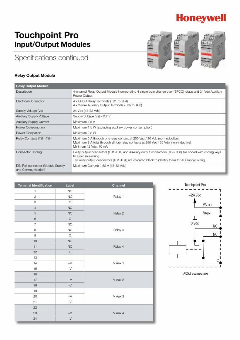
Relay Output Module
Description 4-channel Relay Output Module incorporating 4 single pole change over (SPCO) relays and 24 Vdc Auxiliary Power Output
Electrical Connection 4 x SPCO Relay Terminals (TB1 to TB4) 4 x 2-wire Auxiliary Output Terminals (TB5 to TB8)
Supply Voltage (Vs) 24 Vdc (18-32 Vdc)
Auxiliary Supply Voltage Supply Voltage (Vs) – 0.7 V
Auxiliary Supply Current Maximum 1.5 A
Power Consumption Maximum 1.5 W (excluding auxiliary power consumption)
Power Dissipation Maximum 2.3 W
Relay Contacts (TB1-TB4) Maximum 5 A through one relay contact at 250 Vac / 30 Vdc (non-inductive)Maximum 8 A total through all four relay contacts at 250 Vac / 30 Vdc (non-inductive)Minimum 12 Vdc, 10 mA
Connector Coding Relay output connectors (TB1-TB4) and auxiliary output connectors (TB5-TB8) are coded with coding keys to avoid mis-wiring.The relay output connectors (TB1-TB4) are coloured black to identify them for AC supply wiring
DIN Rail connector (Module Supply and Communication)
Maximum Current: 1.62 A (18-32 Vdc)
Touchpoint Pro
+24 Vdc
VAux+
VAux-
0 VdcNO
NC
C
ROM connection

Input and Output Modules (I/O Modules)
Power Supplies
TPPR-V-1000 Analogue Input Module 4-20mA
TPPR-V-1010 Analogue Input Module mV-Bridge
TPPR-V-1030 Digital Input Module
TPPR-V-1040 Relay Output Module
Touchpoint ProInput/Output Modules
Specifications continued

Touchpoint ProPower Supplies
Specifications
Power Supply Units
Power Supply 120 W (5A) 240 W (10A) 480 W (20A)
Input Voltage Range 85 - 264 Vac; 88 – 360 Vdc
Input Frequency Range 50 - 60 Hz ±6%
Input AC current 1.10 A at 120 Vac 0.62 A at 230 Vac
2.22 A at 120 Vac 1.22 A at 230 Vac
4.56 A at 120 Vac 2.48 A at 230 Vac
Output Voltage 24 Vdc (Adjustable 24 - 28 Vdc)
DC OK Relay contact ratings (max.) 60 Vdc 0.3 A / 30 Vdc 1 A / 30 Vac 0.5 A resistive load
Protection Short Circuit, Overload (current limiting), No load, Over Voltage, Over Temperature
Dimensions (W x H x D) 40 mm x 124 mm x 117 mm 6 mm x 124 mm x 117 mm 82 mm x 124 mm x 127 mm
Operating Temperature -25 °C to +70 °C (-13 °F to 158 °F)
Derating (60 °C to 70 °C) 3 W/°C 6 W/°C 12 W/°C
Storage Conditions -40 to +85 °C (-40 °F to 185 °F), 5% to 95% RH
Operating Humidity 5% to 95% RH (non-condensing)
Label Purpose
N AC Supply Neutral
L AC Supply Live
Earth
Label Purpose
N AC Supply Neutral
L AC Supply Live
Earth
Label Purpose
+ DC Output +V
+ DC Output +V
- DC Output -V
- DC Output -V
DC OK Relay Contact
DC OK Relay Contact
Label Purpose
+ DC Output +V
+ DC Output +V
- DC Output -V
- DC Output -V
DC OK Relay Contact
DC OK Relay Contact
120 W 24 Vdc Power Supply Unit
240 W 24 Vdc Power Supply Unit

Touchpoint ProPower Supplies
Specifications continued
Label Purpose
N AC Supply Neutral
L AC Supply Live
Earth
Label Purpose
+ DC Output +V
+ DC Output +V
- DC Output -V
- DC Output -V
DC OK Relay Contact
DC OK Relay Contact
Label Purpose
Input 1 + DC Supply 1 +V
Input 1 - DC Supply 1 -V
Input 2 + DC Supply 2 +V
Input 2 - DC Supply 2 -V
Output + DC Output +V
Output - DC Output -V
480 W 24 Vdc Power Supply Unit
Power Supply Redundancy Module (RDN Module)
Power Supply Redundancy Module (RDN Module)
Description Suitable for redundant operation of 24 Vdc
Input Voltage Range 8.4 - 36.4 Vdc
Number of Inputs 2
Input Current (max.) 20 A per input
Output Reverse Voltage (max.) 40 Vdc
Output Current (max.) 40 A
Output Voltage Drop 72mV typical for input: 2x10A
Dimension 140mV typical for input: 2x20A
Operating Temperature 36 mm x 124 mm x 127 mm (WxHxD)
Storage Conditions -40 °C to +70 °C (-40 °F to 158 °F)
Operating Humidity -40 °C to +85°C (-40°F to 185°F), 5% to 95% RH
Operating Humidity 5% to 95% RH (non-condensing)
Failure Monitor
RedundancyModule
Output
PowerSupply
ACL N PE
PowerSupply
ACL N PE
24V, 20A24V, 20A Input1
Input2
DC-OK
DC-OK
20ALoad

Touchpoint ProPower Supplies
Specifications continued
Uninterruptible Power Supply Module (UPS)
Backup Battery
Uninterruptible Power Supply Module (UPS)
Description 23.3 Vdc - 30 Vdc
Input Current 70 mA typical internal current consumption Current consumption for battery charging in constant current mode at 24V input 1.7 A typical at battery selector position <10Ah 3.4 A typical at battery selector position >10Ah
Output Voltage 24 Vdc (nominal) in Normal Operation Adjustable in Battery Operation
Output Current max. 25 A in Normal Operations min. 20 A in Battery Operation
Allowed Batteries 2 x 12 V 3.9 Ah – 130 Ah VRLA lead acid type
Dimensions (W x H x D) 46 mm x 124 mm x 127 mm
Operating Temperature -40 °C to +70 °C
Derating 60 °C to 70 °C 0.5 A/ºC
Storage Conditions -40°C to +85°C, 5% to 95% RH
Operating Humidity 5% to 95% RH (non-condensing)
Backup Battery
Description 24 V sealed lead acid battery, 12 Ah or 27 Ah options
Electrical Connection 2 x 12 Vdc batteries in series
Dimensions (W x H x D) 395 mm x 300 mm x 215 mm
Weight 12 Ah version: 15.7 kg
27 Ah version: 25 kg
Operating Temperature -20°C to +45°C
Operating Humidity 10 % to 90 % RH non condensing
Storage Conditions -20°C to +40°C, 10 % to 90 %RH
Storage Lifetime without re-charge 18 months at <5°C, 6 months at 25°C, 3 months at 30°C, 2 months at 40°C
Ingress Protection IP20, NEMA Code 1
Input Voltage (charging) 25 Vdc to 28 Vdc (UPS Supervised)
Output Voltage (when supplying) 20 Vdc to 28 Vdc (dependent on charge level)
Maximum Input Current 3 A
Maximum Output Current 20 A
Environmental Protection Class Pollution Degree 2 (indoor sheltered)
Battery Type FIAMM 12 V 12 Ah FG21202 or FIAMM 12 V 27 Ah FG22703
Fuse Type (inline) Bussman 20 A Fast Acting 1.25” Type ABC-20-R
Current Limit Protection Double pole circuit breaker / Isolator, 20 A
Maximum Altitude 2000 m

Touchpoint ProPower Supplies
Specifications continued
UPS and Battery Box
The UPS connections are as follows:
Terminal Identification Label Purpose
Input DC 24 V + DC Supply +V
- DC Supply -V
- DC Supply -V (spare)
Output DC 24 V 20 A + +V Supply to Touchpoint Pro system
- -V Supply to Touchpoint Pro system
Battery + Battery +
- Battery -
The UPS is equipped with status relays as follows:
Terminal Identification Label Purpose
1Ready
Contact is closed when both batteries are charged, all OK2
3Buffering
Contact is closed when UPS has switched to battery power4
5Replace Battery
Contact is closed when a battery quality fault is detected6
7Inhibit DO NOT USE
8
Part Numbers
Power Supplies
TPPR-V-0500 Power Supply Redundancy Module 40A
TPPR-V-0501 UPS 40A DC Module
TPPR-V-0502 5A, 120W, 24 Vdc PSU
TPPR-V-0503 10A, 240W, 24 Vdc PSU
TPPR-V-0504 20A, 480W, 24 Vdc PSU
TPPR-V-0405 27Ah 24V Battery (2x27Ah 12V in series)
TPPR-V-0406 12Ah 24V Battery (2x12Ah 12V in series)
TPPR-V-2600 Battery Backup Enclosure

Touchpoint ProCommunication/Power Rail
Specifications
Communication / Power Rail
Description 5, 7, 9 or 10-way Communication / Power Rail consists of 1 DIN Rail, 1 Ring Coupling Module (RCM), and a 5, 7, 9 or 10-way Backplane
DIN Rail
Total Width 430 mm
Type TS-35/15
Ring Coupling Module (RCM)
Description Module for connection of DIN Rail mounted I/O modules to Ring Network
Electrical Connection 2 x Ring Network TX / RX Driver Pairs (Each 2-Wire plus Drain)
Supply Voltage 24 Vdc (18-32 Vdc)
Power Consumption Maximum 1 W
Power Dissipation Maximum 1 W
Ring Network Cable Minimum 2 x 2 x 1 mm2 twisted pair, plus Drain and Overall Screen
Operating Temperature -40°C to +65°C
Storage Temperature -40°C to +65°C
Environmental Protection Class Pollution Degree 2 (indoor sheltered)
Connector Coding Ring cable connectors (TB1-TB4) are coded with coding keys to avoid mis-wiring.
DIN Rail connector (Module Supply and Communication)
Maximum Current: 60 mA (18-32 Vdc)
Backplane
Description 5, 7, 9 and 10 I/O slot (excluding first slot reserved for RCM) backplane PCB for providing power and Ring Network connections to the RCM and I/O modules
Electrical Connection 2-wire (+V and –V) at Power Supply Input for 5, 7, 9 I/O Slot Backplane2 x 2-wire (+V and –V) at Power Supply Input for 10 I/O Slot Backplane10-pin backplane connector for connection to RCM and I/O Modules
Maximum Wire Size 6 mm2
Supply Voltage 24 Vdc (18-32 Vdc)
Backplane current Rating Maximum 20 A
Power Supply Connector Rating Maximum 32 V, 41 A
Backplane connector Maximum 32 V, 4.04 A
Environmental Protection Class Pollution Degree 2 (indoor sheltered)
Operating Temperature -40°C to +65°C
Storage Temperature -40°C to +65°C
Ring Coupling Module
Communication / Power Rail
Terminal Identification Label Channel
1 + Ring A In
2 Drain
3 -
4 + Ring B Out
5 Drain
6 -
7 + Ring B in
8 Drain
9 -
10 + Ring A Out
11 Drain
12 -

Touchpoint ProCommunication/Power Rail
Specifications continuedPart Numbers
Communication/Power Rail
For 19’’ Rack enclosure versions
TPPR-V-0520 5 Way Communication/Power Rail
TPPR-V-0525 7 Way Communication/Power Rail
TPPR-V-0530 9 Way Communication/Power Rail
For standard Wall Mount and Floor Standing Cabinet versions
TPPR-V-0540 10 Way Communication/Power Rail
TPPR-V-0541 9 Way Communication/Power Rail with additional RCM
TPPR-V-0542 9 Way Communication/Power Rail with additional DIM
TPPR-V-0543 8 Way Communication/Power Rail with additional DIM and RCM

Touchpoint ProEnclosures
Specifications
19’’ 5U Rack Controller Enclosure
Part Number TPPR-V-0602
Material Mild Steel
Earthing Points M8 (main grounding); other M6
Dimensions (H x W x D) 483 mm x 222 mm x 110 mm
Weight 10 kg
19’’ 5U Rack Remote Unit Enclosure
Part Number TPPR-V-0612
Material Mild Steel
Earthing Points M8 (main grounding); other M6
Dimensions (H x W x D) 483 mm x 222 mm x 110 mm
Weight 9 kg
Wall Mount Controller Enclosures
Part Number TPPR-V-1210 TPPR-V-1220 TPPR-V-1230
Material Mild Steel Mild Steel Mild Steel
Dimensions (H x W x D) 600 mm x 600 mm x 300 mm 800 mm x 600 mm x 300 mm 1200 mm x 600 mm x 300 mm
Approximate Weight 37 kg 46 kg 81 kg
Wall Mount Remote Unit Enclosures
Part Number TPPR-V-1215 TPPR-V-1225
Material Mild Steel Mild Steel
Dimensions (H x W x D) 600 mm x 600 mm x 300 mm 800 mm x 600 mm x 300 mm
Weight 37 kg 46 kg
Floor Standing Cabinets Front Access
Part Number TPPR-V-1250 TPPR-V-1252 TPPR-V-1254
Ventilation Type No Ventilation Natural Ventilation Forced Ventilation
Dimensions (H x W x D) 2000 mm x 800 mm x 600 mm 2000 mm x 800 mm x 600 mm 2000 mm x 800 mm x 600 mm
Approximate Weight 201 kg 201 kg 201 kg
Floor Standing Cabinets Rear Access
Part Number TPPR-V-1260 TPPR-V-1262 TPPR-V-1264
Ventilation Type No Ventilation Natural Ventilation Forced Ventilation
Dimensions (H x W x D) 2000 mm x 800 mm x 600 mm 2000 mm x 800 mm x 600 mm 2000 mm x 800 mm x 600 mm
Approximate Weight 201 kg 201 kg 201 kg

Wall Mount Stainless Steel Div 2/Zone 2 Remote Units
Part Number TPPR-V-1241
Material Stainless Steel
Dimensions (H x W x D) 780 mm x 510 mm x 300 mm
Approximate Weight 42 kg Note: Please be aware that the weight may vary depending on the options selected.
Touchpoint ProEnclosures
Specifications continued
Hazardous Area Enclosure
The Touchpoint Pro range includes a wall mounted enclosure which is certified for use in hazardous areas/locations (ATEX/IECEx Zone 2, Class I Div 2, and Class I (Zone 2)). This enclosure can only be used as a remote unit, no controller option is available.

Honeywell Analytics is able to provide gas detection solutions to meet the requirements of all applications and industries. Contact us in the following ways:
Please Note: While every effort has been made to ensure accuracy in this publication, no responsibility can be accepted for errors or omissions. Data may change, as well as legislation, and you are strongly advised to obtain copies of the most recently issued regulations, standards, and guidelines. This publication is not intended to form the basis of a contract.
HeadquartersEurope, Middle East, Africa Life Safety Distribution AGJavastrasse 28604 HegnauSwitzerlandTel: +41 (0)44 943 4300 Fax: +41 (0)44 943 4398
Customer Service: Tel: +800 333 222 44 (Freephone number)
Tel: +41 44 943 4380 (Alternative number)
Fax: +800 333 222 55Middle East Tel: +971 4 450 5800 (Fixed Gas Detection)
Middle East Tel: +971 4 450 5852 (Portable Gas Detection)
Americas Honeywell Analytics Distribution Inc.405 Barclay Blvd.Lincolnshire, IL 60069USATel: +1 847 955 8200Toll free: +1 800 538 0363Fax: +1 847 955 8210
Asia PacificHoneywell Analytics Asia Pacific #701 Kolon Science Valley (1) 43 Digital-Ro 34-Gil, Guro-Gu Seoul 152-729KoreaTel: +82 (0) 2 6909 0300Fax: +82 (0) 2 2025 0388India Tel: +91 124 4752700
Technical Support CentresHoneywell Analytics Ltd. 4 Stinsford RoadNuffield Industrial EstatePoole, Dorset, BH17 0RZUnited KingdomTel: +44 (0) 1202 645 544Fax: +44 (0) 1202 645 555
Honeywell Analytics ZAC Athélia 4 - 375 avenue du Mistral Bât B, Espace Mistral 13600 La Ciotat France Tel: +33 (0) 4 42 98 17 75Fax : +33 (0) 4 42 71 97 05
Honeywell AnalyticsElsenheimerstrasse 4380687 München GermanyTel: +49 89 791 92 20 Fax: +49 89 791 92 43
Honeywell AnalyticsP.O. Box-455956th StreetMusaffah Industrial AreaAbu DhabiUAETel: +971 2 554 6672 Fax: +971 2 554 6672
EMEA: [email protected] US: [email protected]: [email protected]
www.honeywellanalytics.com www.raesystems.com
Honeywell AnalyticsExperts in Gas Detection
Honeywell Analytics Gas Detection
13455_TPPR Spec Sheet_Enclosures
V1_10/14_EMEAI
© 2014 Honeywell Analytics