hoover dam tunnel spillway damage k. h. houston r. j ... · flow over the side channel spillway...
TRANSCRIPT
Hoover Dam Tunnel Spillway Damage
K. H. Houston R. J. Quint T. J. Rhone
U.S. Bureau of Reclamation
May 1987

Y'Q-3
An Overview of Hoover Dam Tunnel Spillway Damage
K. L. Houston, R. J. Quint, A. T. J. Rhone, M.
Introduction
The Rover Dam tunnel spillways have provided the Bureau of Reclama tion hydraulic laboratories with new and continued opportuniti s for applied research. Early in the feasibility investigation for the original design and construction of the Boulder Canyon Project it became evident that new design and construction technol-ogies would have to be developed to successfully accomplish the mission,. The Bureau of Reclamation Engineering and Research labora-tories-,were expanded to lead this endeavor. The two most prominent laboratories in this period were the Concrete and Hydraulic Labora-tories. During the peak years (1930-1936) of the Boulder Canyon Project design and construction, four hydraulic laboratories played important roles in developing the hydraulic structures for Hoover Dam. These laboratories, all in Colorado, were located at Montrose, Fort Collins, and two sites in Denver. Presently all of the Bureau laboratories, including the sole surviving hydraulic laboratory, are located at the Engineering and Research Center in Denver, Colorado.
The scope of the Boulder Canyon Project was massive. Four 50-ft-diameter tunnels, two on each side of the river, were driven through the canyon walls to divert the river discharge during construction. Ultimately, all of the tunnels were modified for further use as spillways, outlet works, or power penstocks in the completed structure (fig. 1). The outside tunnel in each abutment became a part of the spillway system while the two inner tunnels housed the river outlet works and power penstocks.
Original Investigations
Several spillway alternatives were investigated. The requirements of a high reservoir water surface that had to be maintained for power revenue, a massive flood control pool and unprecedented discharge capacity were challenging criteria. The selected design consisted of twin tunnel spillways with flow control at the reservoir accomplished by two side channel inlet structures, each with four 100-ft (30.48 m) long by 16-ft (4.88 m) high drum gates. The axis of each side channel spillway is nearly normal to the dam axis.
a/ K. L. Houston, Hydraulic Engineer; b/ R. J. Quint, Civil Engineer; and c/ T. J. Rhone, Supervisory Hydraulic Engineer, Bureau of Reclamation, Engineering and Research Center, Denver, Colorado.
Houston
A.M., ASCRa~
M., ASCE~ A., ASCE—
/

DNA SPILLWAY
—el plug
SPILLWAY TUNNEL 10' Steel penstocks — —
Stoney
6_72" Needle
\, . eedle calves _ // ( 13' Penstocks ~ $
Stoney gate PO ER PLANS
j/,~`1 ^~=~,_ Needle valves // /
J
13' Penatoc 4e ~~ aly es
portal road v
6-84" Needle valves
`3C' Steel pe stocks
NEVADA PLAN 0 500 1000
l ' Scale of feet ~~ARIZDNA S°IL L'W A'
POWER a+ion .all outlet work.
-- , /-Stoney gate
r_ Z
Tunnel portal
` \ Intake towers_
50 DIVERSION TUNNELS _Tunne l plugi~
NEVADA SPILLWAY--__`t—
Temporary outle to ~~ El. 1232
Intake to.era ~i~
30' Steel p.n. locksy
E1. 506
ARL2,:C13_A_
50 DIVERSION TUNNELS
TQ`~(~-- Tunnel plu9_l FL'* rev
LONGITUDINAL SECTION
Figure 1. - Plan and section of Hoover Dam.
Construction of the dam and appurtenances was completed in 1936, but the spillways were not used until 1941. At that time a rela-tively small average discharge of about 13,555 ft3/s (384 m3/s) was passed through each spillway for about 4 months. During this operation one of the Arizona drum gates inadvertently dropped, increasing the discharge to 38,000 ft3/s (1076 m3/s) for several hours.
Inspection after this operation revealed essentially no damage in the Nevada tunnel spillway, but massive erosional damage in the Arizona tunnel spillway, near the vertical curve at the diversion tunnel plug. Several possible causes for this damage were discussed, with the most probable being that an abrupt misalinement in the tunnel invert deflected the high velocity flow causing subatmospheric pressures and the formation of vapor pockets. Subsequent implosion of these vapor pockets further downstream caused cavitation damage which destroyed the integrity of the concrete lining and eventually led to the massive erosional damage. The tunnel misalinement was corrected and the concrete damage repaired - leaving a surface finish similar to terrazzo.
In discussing possible protective methods, it was suggested that air introduced into the flow near the concrete surface might provide a "cushioning" effect and prevent cavitation damage. Model studies were performed on a 1:60 scale model of the tunnel spillway to develop a method of naturally injecting air into the spillway flows. After tests on many different schemes, a 2-1/2-ft (0.76-m) high si11, across the invert of the tunnel and a short distance downstream of the tunnel entrance, was developed (fig. 2). Subse-quent air measurement tests indicated large quantities of air
Houston

SECTION 0-0
Y.e
SECTION Y-Y
Ooe1 Cd the IFesew cocrui
Se'~Oriy.W S"'7 stsl-.
BOULDER DAM FINAL LAYOUT WITH AERATION
IN SPILLWAY TRANSITION
DETAIL F DETAIL E
Figure 2. - Aeration device developed from 1942 hydraulic model
intake at the deflectors but no air near the invert at the vertical curve. Sills and dentates at the P.C. of the vertical bend and in the bend itself failed to supply air to the desired areas. Because of the negative results these air induction tests were discontinued.
Recent Investigations
The tunnel spillways were not used again until the 1983 floods. Comparatively low flows [less than 10,000 ft3/s (283 m3/s)] through each spillway were discharged for several hundred hours. Minor cavitation damage occurred, more in the Nevada than the Arizona tunnel. Since it is known that this type of damage is cumulative, it was decided that aeration devices should be installed in both tunnels.
3 Houston

Since the unsuccessful model studies of the late 1930's, much has been learned about cavitation theory. Cavitation is the forma-tion of a void or "bubble" within a liquid. In hydraulic structures, cavitation occurs when local pressure is reduced below atmospheric pressure, usually because of flow surface irregularities. The collapse of these cavitation bubbles as they entered areas of higher pressure caused damage to the flow surface in 1983 at Glen Canyon and Hoover Dams. Providing aeration where the potential for cavitation exists will reduce or eliminate-cavitation damage.
Technology has been developed which predicts cavitation damage by relating pressure to velocity. The parameter which defines this relationship is the cavitation index,6 :
Q = Po Pv 1/2p V2
where Po = reference pressure Pv = vapor pressure P = fluid density V = flow velocity
From past experience, cavitation in hydraulic structures has occurred when the velocity increases or pressure decreases such that the cavitation index drops below 0.20.
Locations for providing aeration in hydraulic structures are based upon this index and the tunnel geometry downstream. [Falvey, Henry T., Cavitation in Hydraulic Structures, Bureau of Reclamation Monograph, Denver, Colorado, yet to be published).] For Hoover Dam spillways, the aerator was located at Sta. 8+75 where a = 0.184 and the flow had already dropped over 200 ft (61 m) through the tunnel. The flow surface upstream of the aeration device will be carefully finished.
An aeration device is composed of a ramp, slot, and downstream transition from the slot to the original lining. These portions of Hoover's aerator design were initially determined based upon designs from Yellowtail and Glen Canyon aeration devices. However, because the design of aeration devices and their effect on down-stream flow patterns was still in the developmental stage, a model study was performed.
Aeration devices were studied with a 1:52.174 scale model of Hoover Dam's Arizona tunnel spillway. The model included a portion of the reservoir, the side channel inlet structure (without controlling drum gates), and the 50-ft (15.24-m) diameter tunnel which is inclined 50° to intersect the long, almost horizontal diversion tunnel - ending with a flip bucket (fig. 3). Test discharges rang
3/ ed from all flows of 5,000 ft3/s (142 m3/s) to a maximum
of 200,000 ftJ/s (5663 ms) which is the design capacity of each spillway tunnel.
4 Houston

L
Figure 3. - Overall view of Hoover Arizona spillway model.
Turbulent flow from the side channel inlet structure, and the flip bucket geometry, produced major aerator design considerations. Flow over the side channel spillway crest created a roller upon impacting the floor and opposite wall of the side channel basin. Flow direction in the basin changed almost 90° before entering the tunnel. Turbulence caused by the changing flow direction and the roller increased in magnitude as the discharge increased. This turbulent flow condition remained throughout the inclined portion of the tunnel and caused many modifications to the original aeration device design to prevent the vent from filling with water.
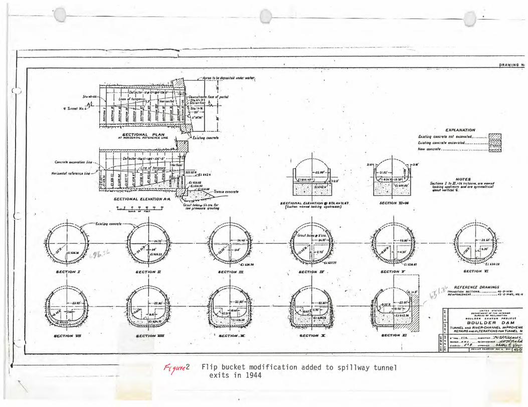
Flip buckets were added in the spillway tunnel exits in 1944 to prevent erosional damage in the river channel downstream. The resulting area constriction at the flip buckets produced three different flow phases:
-Free flow until the tunnel exit closes off at approximately 135,000 ft3/s (3823 m3/s)
•A transient hydraulic jump in the almost horizontal an., steeply inclined sections of the tunnel for discharges between'' 135,000 (3823) and 185,000 ft3/s (5239 m3/s).
-Pressure flow for discharges exceeding 185,000 ft3/s (5239 m3/s).
These flow conditions were all considered in the aeration device design, even though recommended operation is under free flow condi-tions. Addition of the aerator and subsequent enlargement of
5 Houston

DIMENSION AERATION SLOT
NO. I NO.2 NO.3
d 1.20' 3.00 I 3.00'
II 11.46' 17.26' 17.26'
12 18.75 18.75' 15.00'
do 1.25' 1.25' 3.00
8 ( 6- 10" 10`
44• 40^ 40"
Slot No.1
the vent area produced a more stable flow condition and reduced the extremely large pressure fluctuations at the tunnel exit when the hydraulic jump was present in the tunnel.
The initial design for Hoover's aeration device was based upon previous successfully tested air vent installations. The location of the aeration device (Sta. 8+75) was determined by computing cavitation indices over the full range of discharges while maintain-ing a free water surface throughout the entire structure. Prelimi- nary aeration devices are shown schematically on figure 4. For' the final design significant changes were made to these preliminary designs, particularly to the ramp invert height [from 1.2 (0.37) to 3 ft (0.91 m) high], ramp angle (from 6 to 10°), and aeration area (elimination of the groove). These changes were necessary to provide a large aeration area under the jet and prevent submergence of the slot during normal operation.
The turbulent, spiraling flow at the aerator location greatly affected the final aerator design. Most design changes were made to help contain this flow and prevent water from filling the slot. Eliminating the aeration groove by beginning the transition back to the original tunnel lining at the base of the upstream ramp
SECTION A-A
Figure 4. - Preliminary aeration devices tested during recent hydraulic model studies.
6 Houston

allows the slot to drain automatically and will be easier to construct. Operation of the model for the flow of 20,000 ft3/s (566 m3/s), with the final aeration device installed, is shown in figure 5. The dramatic changes from the original geometry revealed the value of laboratory modeling.
Figure 5. - Final aeration device passing 20,000 ft3/s.
Proposed Modifications
The final design of the aeration devices for the Arizona and Nevada spillways is identical in size and location. In prototype, the overall length of each device (fig. 6) is 42.25 ft (12.88 m) with the upper 17.25 ft (5.26 m) consisting of the ramp area. This ramp projects 3 ft (0.9 m) into the flow at the invert and feathers to the original concrete surface at 35° on each side of the tunnel crown. The lower 25 ft (2.62 m) of the device consists of a concen-tric 5-ft (1.52 m) offset away from the flow which transitions back to the original tunnel lining at a rate of 5 ft (1.52 m) along the flow to 1 ft (0.3 m) perpendicular to the flow. The beginning of the 5-ft (1.52 m) offset is at invert Sta. 8+75 and approximately 275 vertical feet (83.8 m) above the elbow invert. This location and configuration provides aeration to the flow and protects the elbow area from cavitation damage.
The current schedule for construction of the aeration devices and repair of the damage from the 1983 spill is as follows:
Begin Nevada aeration device construction October 2, 1985 and spillway repair
Complete Nevada spillway work May 15, 1986
7 Houston

Begin Arizona aeration device construction October 1, 1986 and spillway repair Complete Arizona spillway work May 15, 1987
—Existing tunnel
4 S011hoy tunnel --Motch to existing tunnel
61~
a~ Limits of ,\ oerotion slo 11~ •
50 ,
EL 92136 / 510. 8.63. 91.~
':✓
-<Sto. 8+7$.00 X \
£1 90814
Romp
—El. 888 99
~'--Sta 9.00.40 Match to existing tunnel
f1.67Z87
PROFILE ALONG ¢ SPILLWAY TUNNEL
of
f runnel
SECTION A-A FIGURE 6: PROTOTYPE AERATION DEVICE CONFIGURATION
This schedule keeps one of the spillways operational should releases be required from Lake Mead. The time between the work in the two spillways is provided in the event spring runoff inflow exceeds the capacity of the river and power outlets and the available storage. The schedule also allows for the majority of the work to be completed prior to anticipated construction of the new Hoover Dam visitor facilities.
During installation of the aeration devices, damage from the 1983 spill will be repaired. Damage to the Arizona spillway is relatively minor with only four small areas of cavitation damage in the elbow area. These will be repaired by using underwater grinding techniques which will eliminate the expense of dewatering the Arizona spillway tunnel. Damage in the Nevada spillway is more extensive with approximately 20 yds3 (15.3 m3) of the tunnel lining in the elbow area removed during the 1983 spill. Repair of this damage will require dewatering of the tunnel - probably by use of a bulkhead and sump pumps at the end of the tunnel.
In addition to repairing the cavitation damaged areas, much work will be required to restore smooth, uniform concrete flow surfaces. Calcite deposits, concrete spalling, old form lines, etc., must
8 Houston
all be ground to acceptable bevels to prevent cavitation damage due to offsets. Required bevels are 15 run:l rise approaching the aeration device and 20 run:l rise immediately upstream of the aeration device offset and in the downstream area. Special attention will be concentrated on the area immediately upstream of the aeration device as this will be the area of the highest velocities and thus the highest cavitation potential. New concrete in the aeration device ramp will need to be kept within stringent construction tolerances in order to avoid cavitation producing offsets.
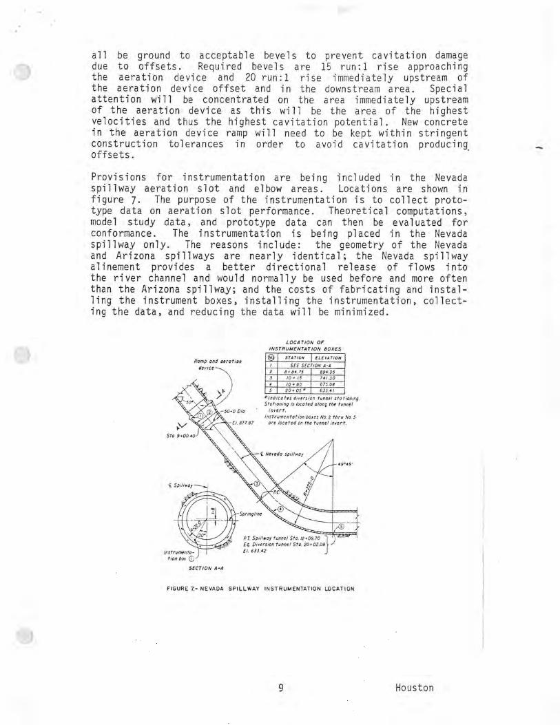
Provisions for instrumentation are being included in the Nevada spillway aeration slot and elbow areas. Locations are shown in figure 7. The purpose of the instrumentation is to collect proto-type data on aeration slot performance. Theoretical computations, model study data, and prototype data can then be evaluated for conformance. The instrumentation is being placed in the Nevada spillway only. The reasons include: the geometry of the Nevada and Arizona spillways are nearly identical; the Nevada spillway alinement provides a better directional release of flows into the river channel and would normally be used before and more often than the Arizona spillway; and the costs of fabricating and instal-ling the instrument boxes, installing the instrumentation, collect-ing the data, and reducing the data will be minimized.
LOCATION OF INSTRUMENTATION BOXES
Romp and aeration device
*9+0a40
io.
877.87
St
f Spillwoy
® STATION I ELEVATION
I SEE SECTION A-A 2 8.84.75 894.05 3 10 + 15 741.30 4 f0. 80 675.08 5 20+05 0 633.41
*Indicates diversion tunnel stationing. Stationing is located along the tunnel
nvert. Instrumentation, boxes No. 2 thru Na. 5
ore located on the tunnel invert.
C Nevado spillway
a / 49 19'
I r R. L Spillway tunnel Sto. 12.09.70
Eq. Diversion tunnel Sto. 20.02.081
Instrumento- El. 633.42
tion box G SECTION A-A
FIGURE 7.— NEVADA SPILLWAY INSTRUMENTATION LOCATION
Houston

The instrument boxes will be installed during the spillway repair construction. Because of the relatively infrequent use of the spillways, the instrumentation will not be added until just prior to use of the spillway. Because of the importance of the water
and power in this area, no testing of the spillway or instrumenta-tion is planned. The first "test" will come when releases are required through the spillway.
When it is anticipated that use of the spillway will be required, the instrumentation boxes will be equipped with remote data record-, ing equipment. This precludes installation of conduits and wiring. Data collected will include pressures, velocities, and hopefully, air-water concentrations downstream of the aeration device. This data will be useful for updating the current aeration device information and will be applied to future designs.
Appendix. - Bibliography
Bradley, J. N., "Study of Air Injection into the Flow in the Boulder Dam Spillway Tunnels - Boulder Canyon Project'" USBR Report Hyd. 186, Denver, Colorado, October 1945.
Colgate, D. M., Hydraulic Model Studies of Aeration Devices for Yellowtail Dam Spillway Tunnel, Pick-Sloan Missouri Basin Program, Montana, Bureau of Reclamation, Report REC-ERC-71-47, Denver, Colorado, December 1971.
Pugh, Clifford A., "Modeling Aeration Devices for Glen Canyon Dam," Proceeding from 1984 ASCE Hydraulics Specialty Conference, Coeur d'Alene, Idaho, August 1984.
10 Houston


rv- ") ~ - ~~2
HYDRAULIC MODEL STUDIES OF HOOVER DAM, ARIZONA, TUNNEL
SPILLWAY - AERATOR DESIGN
Month 1992
U.S. DEPARTMENT OF THE INTERIOR Bureau of Reclamation
Denver Office Research and Laboratory Services Division
Hydraulics Branch
7-2090 (4-81) Bureau of Reclamation TECHNICAL REPORT STANDARD TITLE PAGE
1. Tx1XO. G EIyKY1t !iT Ft ••-`. a 3. RECIPIENT'S CATALOG NO.
4. TITLE AND SUBTITLE 5. RE$ABnthAY992
HYDRAULIC MODEL STUDIES OF HOOVER DAM, ARIZONA, TUNNEL 6. PERFORMING ORGANIZATION CODE
SPILLWAY - AERATOR DESIGN D-37.J X 1
7 tli4i H. Frizell B. PERFORMING ORGANIZATION ' REPORT NO.
R 9. PERFORMING ORGANIZATION NAME AND ADDRESS 10. WORK UNIT NO.
Bureau of Reclamation 11. CONTRACT OR GRANT NO. Denver Office
Denver CO 80225 13. TYPE OF REPORT AND PERIOD
COVERED 12. SPONSORING AGENCY NAME AND ADDRESS
Same 14. SPONSORING AGENCY CODE
15. SUPPLEMENTARY NOTES DIBR
Mirrnficbe and hard copy available at the Denver Offico, D@Aver, GGIorado- 16. ABSTRACT
Recent cavitation damage in steeply sloped tunnel spillways has prompted investigation of aerator design. The hydraulic model of the Hoover Dam Arizona tunnel spillway included the side channel spillway, the steeply sloped tunnel with a vertical bend and the long, almost horizontal, section ending with a flip bucket. An aerator was installed in the physical model according to the location determined by a mathematical model and the final aerator dimensions determined during the physical model study. The final design for the aerator included a ramp extending to 350 either side of the crown with a ramp angle of 100 and a 3-ft invert height. The air slot and downstream transition section were formed by a concentric 5-ft offset away from the flow which returned to the original tunnel lining on a 5:1 chamfer. This aerator geometry provided air underneath the jet until the slot was submerged by the bucket. Pressures were measured downstream of the aerator, through the vertical bend, and at the flip bucket.
17. KEY WORDS AND DOCUMENT ANALYSIS
a. DESCRIPTORS-- hydraulic model/ tunnel spillway/ *spillway aerator/ pressure head/ flip bucket/ flow distributions/ high velocity flow/ 'cavitation
b. IDENTIFIERS--
Hoover Dam Arizona tunnel spillway, Boulder Canyon Project, Boulder City, c. NeVaelaField/Group COWRR: SRIM:
18. DISTRIBUTION STATEMENT
Available Nat~d~l, Tech
19. SECURITY CLASS (THIS REPORT)
21. NO. OF PAGE
DivIkion,,,528 frothe nicaljnformatigtiSer'w,i.ce.,--©pe~ations
Or oyal Ro•ad,_SQlingfield,~irginio 22161. UNCLASSIFIED 20. SECURITY CLASS
(THIS PAGE) 22. PRICE # A.
UNCLASSIFIED

R-92-XX
HYDRAULIC MODEL STUDIES OF HOOVER DAM, ARIZONA, TUNNEL
SPILLWAY - AERATOR DESIGN
by
Kathleen Houston Frizell
Hydraulics Branch Research and Laboratory Services Division
Denver Office Denver, Colorado
Month 1992
UNITED STATES DEPARTMENT OF THE INTERIOR * BUREAU OF RECLAMATION

ACKNOWLEDGMENTS
The model study was initiated to design an aerator for the Hoover Dam tunnel spillways Designers who requested the study and provided assistance included Harold Blair, Robert Quint, and Steve Higinbotham.
Dr. Henry Falvey provided technical assistance in aerator design. Cheryl States drafted model drawings and gathered data. The model was constructed by the Hydraulics Branch shop personnel. Photography was by Wayne Lambert.
M

CONTENTS
Glossary............................................................
Purpose............................................................
Introduction.........................................................
Results.............................................................
Application.......................................................... Hydraulic model features ................................................ Initial model tests - no aerator ............................................. Aerator design concepts .................................................
Hoover aerator design ................................................ Preliminary aerator designs ...............................................
Original design (aerator No. 1) .......................................... First modification (aerator No. 2) ........................................ Second modification (aerator No. 3) ......................................
Final aerator design .................................................... Aerator flow characteristic .............................................
Pressure profile downstream of the aerator .................................... Investigation of flow conditions and pressures produced by the flip bucket ..............
Recommended modification ............................................ Prototype instrumentation ................................................ Bibliography......................................................... Appendix - cavitation index computations ....................................
TABLES
Table
1 Preliminary aerator dimensions ...................................... 2 Geometry for other tunnel spillway aerators ............................. 3 Pressures (ft) recorded at the flip bucket ...............................
FIGURES
Figure
la Plan and section of the Arizona side channel spillway and tunnel .............. lb ~i tlV :` ? . . . . . . . . . . . . . . . . . . . . . . . . . . . . . . . . . . . . . . . . . . . . . . . . . . . . . . .
2 Flip bucket modification added to spillway tunnel exits in 1944 ............... 3 Overall view of the Hoover Dam Arizona tunnel model ..................... 4 Flow through the tunnel without an aerator .............................. 5 Stilling action in the side channel spillway for a discharge of
100,000ft3/s ................................................. 6 Turbulent flow through the spillway tunnel transition section
(Q = 100,000 ft3/s) .............................................
iii
Page
CONTENTS - Contents
Figure Page
7a Flip bucket at the spillway tunnel exit discharging 135,000 ft3/s with a free flow surface .........................................
7b The transient hydraulic jump in the tunnel at 145,000 ft3/s ................... 7c Pressurized tunnel flow at 190,000 ft3/s ................................ 8 Graphical representation of cavitation indexes for Hoover Dam
Arizona spillway .............................................. 9 Cavitation damage in the vertical bend of the Hoover Dam Nevada
spillway(1983) ............................................... 10 Schematic of aerator designs ........................................ 11 Initial aerator design - flow of 20,000 ft3/s .............................. 12 First modification of aerator design - flow of 20,000 113/s ................... . 13 Second aerator design modification - flow at 20,000 ft3/s ................... . 14 Final aerator design .............................................. 15 Discharge curve for Hoover Dam Arizona spillway ........................ 16 Final aerator design - jet impacting upstream of the vertical bend for
a discharge of 20,000 ft3/s ........................................ 17 Final aerator design - fins impinging on the tunnel crown for a discharge
of 100,000 ft3/s ............................................... 18 Final aerator design - transient hydraulic jump downstream of the aerator
for a discharge of 145,000 f0/s .................................... 19 Final aerator design - fully submerged aerator and pressure flow in the
tunnel for a discharge of 191,000 ft3/s ............................... 20 Pressure profiles downstream of the air slot for 20,000 ft3/s ................. . 21 Typical stripchart recording of pressures at the flip bucket for
175,000ft3/s ................................................. 22 Model dynamic pressures at the flip bucket crown for a prototype
discharge of 175,000 f0/s ........................................ 23 Modified flip bucket passing discharge of a 200,000 ft3/s ................... . 24 Locations of prototype instrument boxes ...............................
iv

GLOSSARY
d = ramp height 0 = ramp angle a = angle of inclined tunnel o = angle of inclined tunnel minus ramp angle a - 0 do = depth of offset away from invert 12 = length of downstream transition section p = fluid density o = cavitation index po = reference pressure pv = vapor pressure V = flow velocity x = horizontal distance under the jet from the downstream end of the ramp
L = cavity length under the jet = X cos a
y = depth of flow normal to surface So = tunnel slope = tan a g = gravitational constant Qe = air flow rate QW = water discharge
v

INTRODUCTION
Hoover Dam, Boulder Canyon Project, is located on the Colorado River 36 miles southeast of Las Vegas,
NV, on the Nevada-Arizona state line. The dam eliminated the constantly recurring cycles of flood and
drought in the southwest. Hoover Dam forms Lake Mead which provides irrigation water and hydropower
to southern California, Arizona, Nevada, and Mexico. Lake Mead is also a popular recreation site.
Two 50-ft-diameter inclined tunnel spillways, each with a maximum design discharge capacity of
200,000 fees at reservoir elevation 1232, are major features of the dam. Upstream of the tunnels are two
side channel spillways, each controlled by four 100- by 16-ft drum gates (fig. 1). The spillways have
passed flows only twice in their history - in 1941 and 1983. Normally releases are made only through
the powerplant.
In 1941 extensive damage to the concrete tunnel lining occurred in the Arizona spillway. The damage
was thought to be a result of a tunnel invert misalignment which produced cavitation and subsequent
erosion. The tunnel misalignment and damaged concrete lining were repaired. Flip buckets were also
added to both tunnel exits to prevent erosion of the steep-walled canyon downstream (fig. 2). In the
spring of 1983, the spillways operated again but with smaller, shorter duration discharges. Cavitation and
erosion damage occurred in the elbow area of the Nevada spillway, producing a hole 35 ft long, 6.83 ft
wide, and 3 to 4 ft deep. This cavitation damage, although minor compared to that of 1941 and the
extensive damage at Glen Canyon Dam, prompted the model study. Hoover Dam model studies were
conducted from December 1983 to February 1985. The Arizona spillway was modeled to determine the
correct location and configuration of an aerator for both tunnel spillways.
Introducing air between the jet and the flow surface may reduce the potential for cavitation damage.
Previous experiences at other spillways of similar geometry - Yellowtail (Colgate, 197 1) and Glen Canyon
(Pugh, 1984) - demonstrated that aerators reduce the potential for cavitation damage. This model study
was conducted to determine the optimum aerator location and geometry for the Hoover Dam tunnel

spillways. The model study was necessary because no standardized aerator design criteria are available.
Addition of these aerators should prevent future cavitation damage.
RESULTS
1. The aerator should be located at Sta. 8+75 in both spillway tunnels.
2. The aerator consists of an upstream ramp, a slot or area for air passage, and a transition back to the
original tunnel lining. The ramp lifts the jet allowing aeration between the jet and the flow surface. The
slot supplies air from above the free water surface to the underside of the nappe. The transition
downstream of the slot returns the offset created by the slot back to the original lining. Final aerator
dimensions are shown on figure 14.
3. With the aerator and a free water surface for all flows, a maximum discharge of 203,000 ft3/s is
attained through each spillway at reservoir 1232.
4. The flip bucket at the end of the spillway tunnel produced several different flow conditions. For
discharges above 135,000 Wls the flow area constriction at the flip bucket caused a transient hydraulic
jump in the tunnel Large pressure fluctuations occurred in the flip bucket area while the hydraulic jump
was in the tunnel. These fluctuations continued as the jump moved upstream until the tunnel entrance was
sealed and the tunnel became pressurized. Pressure flow ended the fluctuations, but the maximum
spillway capacity decreased to 191,000 Wls at reservoir elevation 1232. The magnitude of the model
pressure fluctuations caused concern for the structural integrity of the prototype tunnel. Therefore,
operating capacity for each spillway tunnel should be restricted to 135,000 Wls. To produce a free water
surface in the tunnel for all flows, the area constriction at the flip bucket must be alleviated. This can be
accomplished by providing a flow area at the flip bucket equal to or greater than that produced by
removing 40 ft of the tunnel crown to the width of the flip bucket vertical side walls.
7

APPLICATION
The geometry of future spillways should be determined so that cavitation producing pressures will not
occur. If this is not feasible, and the spillway geometry and flow velocities indicate the potential for
cavitation, a means of providing aeration must be established.
The general aerator configuration developed for the Hoover tunnel spillways could be used in the design
of aerators for other tunnel spillways. Combining the air slot and downstream transition back to the
original lining is particularly applicable to any aeration device because this allows the slot to drain and
requires less formwork during construction.
HYDRAULIC MODEL FEATURES
Similarity by Froude relationship was maintained by the model. GIs tl: ° prccMing sentence. tit be .re,;- a%---cd
by "Since it;rce-N prcdo-aj.01.e, the silo,"ie.i Was ;.t~;s :;f:;::3 otn the ; p1' Froud3 , miinber.
sin,ihultv."`I? The model scale, 1:52.174, was based on the pipe size that would produce accurate results
and the largest model for the space available. The model included a portion of the reservoir area and the
entire Arizona spillway. The model is shown on figure 3.
The 486.75-ft-long side channel spillway was represented by a model length of 9.33 ft. Flow from the
side channel spillway enters the tunnel which transitions from a flat-bottomed trough shape to a
50-ft-diameter tunnel. A 0.958-ft-diameter pipe on a 50° inclined slope represented the model tunnel.
The 225-ft radius vertical curve scaled to a 4.31-ft radius curve and the nearly horizontal 1,390.6-ft-long
downstream tunnel scaled to 26.65 ft. The terminal structure in the tunnel is a 105.67-ft-long flip bucket
represented by a model length of 2.03 ft.
The 587.6-ft drop from the maximum reservoir water surface to the flip bucket scaled to 11.26 ft.
3

At maximum reservoir elevation 1232, the 26.6-ft head over the side channel spillway crest scaled to 0.51
ft, producing a maximum free flow discharge of 203,000 Wls modeled by 10.32 fees. The four 100- by
16-ft drum gates were not modeled because it was determined that they would not affect the study results.
The overflow crest and spillway side channel were modeled using sheet metal. The transition section from
the side channel to the tunnel was made of high-density polyurethane foam. The tunnel was modeled
entirely of clear plastic with a removable section for the aerator. Clear plastic allowed all aspects of the
tunnel flow to be observed. Water was supplied to the model by the permanent laboratory supply system
and measured by Venturi meters. Reservoir elevations were measured upstream of the side channel
overflow crest with a hook gauge. The correct tailwater was maintained using prototype tailwater
elevations for the upper gauging station from drawing 45-D-908.
The model was tested with prototype discharges of 5,000, 20,000, 50,000, 100,000, 145,000, 175,000, and
200,000 Wls. Documentation included visual observations of the flow patterns, pressure measurements
along the tunnel invert downstream of the air slot, static and dynamic pressure measurements at the flip
bucket, photographs, and video tape recordings.
Air demand or air velocities could not be measured in the model due to the slot configuration and the
splashing produced by the turbulent flows. Also the relationship between model and prototype dynamic
pressures and airflow rates were not determined. Research is currently?? underway which will attempt
to determine this relationship (Pinto and Neidert, 1982; Frizell, 1985).
INITIAL MODEL TESTS - NO AERATOR
Initial model testing was performed without an aerator to compare flow conditions before and after
installation of the aerator (fig. 4). Initial testing indicated two flow conditions that greatly influenced
aerator design:
9

• Spiraling, turbulent flow developing in the side channel spillway and continuing through the
proposed aerator location. Previous model studies did not address turbulent flow through the
inclined portion of the tunnel (Bureau of Reclamation, 1938).
• The flow area constriction at the flip bucket producing a transient hydraulic jump in the tunnel
during high discharges. Flow over the side channel spillway crest creates a roller upon
impacting the floor and opposite wall of the side channel basin. The flow then turns almost
90° before entering the tunnel (fig. 5). The turbulent spillway flow caused by these two
phenomena increases as the discharge increases and continues through the transition and
inclined portion of the tunnel (fig. 6). Effects of the turbulent flow on individual aerator
designs are discussed in detail later in this report.
Pressures were measured to determine possible pressure changes caused by introducing air into the flow.
Water surface profiles were noted to reference a comparison with the profiles created by addition of an
aerator. After addition of the first aerator, it was evident that documentation of water surface profiles was
not necessary. Observations of the flow patterns were enough to determine the applicability of the aerator
design.
Flip buckets had been added to the spillway tunnel exits in 1944 to prevent erosion damage in the river
channel downstream (Bradley, 1944). Initial model operation revealed three different tunnel flow
conditions caused by the flow area constriction at the flip bucket:
• Free flow until the tunnel exit closes off at approximately 135,000 ft3/s (fig. 7a). A transient
hydraulic jump in the almost horizontal or the steeply inclined tunnel for flow rates between
135,000 and 185,000 ft3/s (fig. 7b).
• Pressure flow for discharges exceeding 185,000 ft3/s (fig. 7c).
6y

Each of these flow conditions were considered during aerator design. Initial model operation revealed
large pressure fluctuations at the flip bucket with the hydraulic jump in the tunnel.
AERATOR DESIGN CONCEPTS
Cavitation is the formation of a void or "bubble" within a liquid. In hydraulic structures, cavitation occurs
when local pressure is reduced below atmospheric pressure, usually because of irregularities on the flow
surface. As these bubbles enter an area of higher pressure, they collapse causing damage to the flow
surface. The parameter which predicts incipient cavitation is a relationship between pressure and velocity
known as the cavitation index or flow sigma:
o = P° - P, (1) 1/2 p V2
where:
po = reference pressure
p„ = vapor pressure of liquid
p = fluid density
V = flow velocity
This relationship shows that the cavitation index decreases as the velocity increases. A computer program
such as HFWS (need to define??) that determines the free water surface profile throughout the entire
structure can be used to determine cavitation indexes. Hydraulic structures with a cavitation index greater
than 0.20 have not experienced major cavitation damage.
Providing aeration to high-velocity flow reduces or eliminates the potential for (Peces&ary ) cavitation
damage. Aeration is most often achieved using aeration grooves or offsets. If possible, aerators should
be placed where sigma is greater than 0.20 to provide air to the flow surface boundary throughout the
42

entire area where cavitation may occur. In practice this is not always possible, in which case, the aerator
may have to be placed downstream, where 6 is <0.20, and the surface upstream carefully aligned and
finished. Aerator design is based upon the correct configuration of a ramp or deflector, a groove or air
slot, and a transition from the air slot back to the original flow surface. The following equations were
used to determine the initial geometry of the aerator for Hoover Dam tunnel spillways; the parameters are
defined in the glossary. (These are quite simplified equations and should be used to determine the
gross dimensions if an aerator with further refinement done using a physical model study. (€ it
clear? 19 These equations will provide reasonable results assuming a standard installation is being
proposed.
The ramp upstream of the aerator is required to lift the underside of the flow nappe over the air slot to
allow air entrainment and to prevent the slot from filling with water. The jet trajectory is a function of
the ramp height, ramp angle, flow velocity, and pressure under the nappe. The jet trajectory for shallow
flow depths and neglecting reduced pressure under the nappe is given by:
y=xtand) — CJX a (2) 2 VZ COS2
If possible, the jet from the ramp should impact at or downstream from the location of the minimum
calculated cavitation index. To avoid excessively large fins, the jet trajectory should not impact in a
concave vertical bend. The ramp angle is calculated to produce the desired jet impact area where the
distance, x, to the impact area is estimated:
Cost 40 (SO — tan t)) = 9w (3 )
The ramp height is then chosen so the aeration area will not be submerged or the downstream tunnel
closed off by fins. Initial ramp height is estimated as equal to 0.2 times the flow depth for the design
discharge. d wlkat' E For circular conduits the ramp should be maximum at the invert and a feather out
to zero at the free water surface of the design discharge. Normally up to the springline will be
adequate. (adequate for what`. not clear.)
7

The aeration area is designed to provide adequate air quantities without exceeding a maximum air velocity
of 300 ft3/s. The air entrainment mechanism is a function of:
• Shear zones between the air and water surface
• Air-water mixture under the nappe
• Jet reattachment to the downstream surface
• Turbulence
• Viscosity and surface tension
These mechanisms are not fully understood; however, air demand may be estimated based upon the flow
velocity of the water and the ramp angle upstream of the air slot. In circular conduits, the air slot must
extend above the maximum water surface and the required airflow rate estimated by:
V2 cos3 4) (So - tan 4) 2 In
4 yy
The airflow rate, Qa, divided by maximum allowable air velocity, 300 ft/s, produces the initial estimate
of the air slot area.
A transition back to the original flow surface is required downstream of the air slot. This transition is
necessary to prevent the slot from submerging, to provide space under the jet nappe, and to prevent
impingement of the jet on the sides of the tunnel. For a free draining air slot the transition should begin
at the bottom of the vertical face formed by the ramp and slot and converge on a straight line back to the
original flow surface.
These criteria?? will provide general guidelines for design of an aerator. Reasonable results for
estimating aerator dimensions will be obtained using these guidelines. However, a hydraulic model study
should be conducted to refine the aerator design. More research is needed before the air entrainment
mechanisms are fully defined and easily applied to an aeration device. Also, extensive model prototype
8

comparisons of air entrainment mechanisms are essential technology is constantly being updated (Henry T.
Falvey, 1989).
Hoover Aerator Design
The previous guidelines and equations were used for the initial Hoover aerator design. However, during
model testing several changes were made to the aerator that depart from these guidelines.
Cavitation indexes were computed throughout the entire spillway structure (appendix). These indexes
predicted that cavitation producing pressures would occur, a < 0.20, in the inclined tunnel and downstream
of the vertical bend for several hundred feet (fig. 8). The increased pressure in the vertical bend would
cause any cavities of low pressure to implode, producing damage to the concrete lining. Comparing these
results with prototype tunnel spillway damage in 1941 and 1983 confirmed the computer program results
(fig. 9). The location of the aerator for Hoover tunnel spillways was based upon the value of the
cavitation index and the tunnel geometry. Because of the large area needing aeration and the complicated
geometry farther upstream in the tunnel the aerator was placed at Sta. 8+75 where the cavitation index
was 0.184 for the flow rate determined to be most critical. Because a is <0.20 at this location the surface
upstream must be carefully aligned and finished.
The original aerator geometry was determined using basic design guidelines. Two major changes were
later incorporated into the geometry - the ramp extended beyond the tunnel springline and the air slot was
combined with the downstream transition. All aspects of the aerator design will be discussed in more
detail in the following sections.
9

PRELIMINARY AERATOR DESIGN
Three aerators were tested before the final design was determined. The original aerator design used the
general design concepts and knowledge of previously designed tunnel spillway aerators. Turbulent
approach flow and the transient hydraulic jump in the tunnel required significant modifications to the
original aerator design. Each modification was the result of flow observations made during model
operation.
For each design, the upstream ramp ended at Sta. 8+75; however, most other aspects of the original aerator
geometry were modified. The dimensions for each preliminary aerator design are listed in the following
table and shown schematically on figure 10.
10

Table 1. - Preliminary aerator dimensions.
Aerator No.
Ramp height d (ft)
Ramp angle (degrees)
Ramp length (ft)
I Air slot
dimensions (ft) Downstream slot
offset do Slope of
downstream transition
Transition length (ft)
Total aerator
length (ft)
1 1.20 6 11.46 5 x 5 extends 1.25 1:15 18.75 30.21 above theoretical max. w.s.
2 3 10 17.26 5 x 5 concentric 1.25 1:15 18.75 36.01
3 3 10 17.26 5 x 5 concentric 3 1:5 15 32.26
Table 2. - Geometry for other tunnel spillway aerators.
Tunnel Tunnel Ramp Ramp Ramp Downstream Slope of Transition Total diameter slope a angle 0 height d length Air slot slot offset downstream length (ft) length
(ft) (degrees) (degrees) (ft) (ft) (ft) transition
Glen Canyon 41 35 7.8 0.58 4.27 4 x 4 1.0 1:20 20 28.27
Blue Mesa 21 55 6 0.83 8 3 X 3 fully 0.67 1:15 10 21 concentric
Yellowtail 32 55 6.34 0.25 2.25 3 X 3 0.5 75-ft radius 8.65 13.90

Aerator geometry and subsequent flow patterns will be described and evaluated in the following sections. A
representative discharge of 20,000 ft3/s was chosen for visual comparison of the flow through each aerator
configuration.
Original Design (Aerator No. 1)
Typical proportions from previous aerators, shown in table 2, were used as guidelines to develop the initial
Hoover aerator configuration.
A ramp angle and downstream transition section of similar magnitude to the previous aerators was chosen.
A 6° ramp angle and a ramp height, d, equal to 0.2 times the flow depth at 15,000 W/s were chosen. The
ramp length was then calculated. Using a 15:1 sloping transition and choosing the downstream slot offset,
do = 1.25, the transition length was determined (fig. 10).
Initial operation of the model with this aerator immediately showed the inadequacy of the design. Aeration
was provided only for discharges less than 75,000 ft3/s; at greater discharges the flow depth and turbulent
water surface drowned out the air slot. Major problems of this original air slot design were:
• Inadequate ramp angle and height
• Flow depth that exceeded the top of the air slot
The flow depths were too large in proportion to the ramp angle and height to sufficiently lift the jet and
provide adequate aeration. This observation was supported by the short cavity length under the jet
downstream of the slot at 20,000 ft3/s (fig. 11). As the discharge increased the jet returned to the invert sooner
and provided less aeration under the nappe, until the flow depth exceeded the top of the air slot. Once this
occurred the air slot became submerged and did not provide aeration for discharges exceeding 75,000 ft3/s.
12

The hydraulic jump in the tunnel for discharges exceeding 135,000 ft3/s affected the aerator performance.
When the hydraulic jump was located in the vertical bend, slight fluctuations in the location of the jump
caused the aerator to alternate between supplying air and being submerged. Very large pressure fluctuations
in the vicinity of the air slot were produced under this condition. As the discharge increased, the jump
gradually moved from the vertical bend up the inclined portion of the tunnel. The air slot then became fully
submerged.
First Modification (Aerator No. 2)
Initial modifications to the aerator design increased the ramp angle from 6° to 10°, the ramp height from 1.2
to 3 ft, and extended the air slot completely around the tunnel circumference (fig. 10).
Aerator performance improved for all discharges. The increased ramp angle and height lifted the jet further
from the invert increasing the cavity length under the jet and, thus, flow aeration.
Extending the air slot completely around the tunnel prevented the turbulent flows and large flow depths a
associated with free flow from totally submerging the slot. For discharges greater than 100,000 f 3/s, the jet
leaving the ramp impinged upon the downstream edge of the slot and on the transition. This created back
flows that partially filled the slot. However, the slot was submerged only when the transient hydraulic jump
moved upstream of the aerator. The concentric slot and increased ramp height greatly improved the aeration
capability of the aerator (fig. 12). However, to prevent back flows into the slot, either the jet leaving the ramp
had to be more confined or do, the offset away from the original tunnel invert, had to be increased.
Second Modification (Aerator No. 3)
The second modification increased the downstream slot offset from 1.25 to 3 ft and shortened the transition
to return to the original tunnel lining to 15 ft on a 5:1 slope (fig. 10). These changes increased the aeration
area available under the jet. Flow patterns for small discharges were not altered by these changes (fig. 13).
13

For free flow discharges exceeding 135,000 fees, the increased aeration area immediately downstream of the
ramp provided a more stable flow condition. However, as the maximum free flow discharge was approached,
turbulence in the jet leaving the ramp still caused return flow to the slot. The transient hydraulic jump did not
totally submerge the air slot until approximately 175,000 Wls had been reached. Final modifications were
made to the aerator to prevent return flows to the slot.
FINAL AERATOR DESIGN
Both the upstream ramp and the downstream slot were modified for the final design. Previous modifications
achieved adequate cavity length under the jet; however, when the flow depth exceeded the springline, turbulent
flow still impinged on the side of the tunnel and returned upstream to the slot.
To confine the flow, the ramp was extended above the springline to 350 on either side of the crown. The
ramp was formed by a 24.18-ft radius, whose center was 1.67 ft above the tunnel centerline (fig. 14). The
ramp angle and invert height, 10° and 3 ft, respectively, were not modified. (The ramp length as constructed
in the prototype was 17.25 ft). The aerator ramp usually (??) does not extend above springline due to the
possibility of creating fins downstream or because of construction complications. However, in this case, an
extended ramp was required to confine and direct the turbulent jet away from the side of the tunnel.
The downstream slot offset, do, away from the original tunnel invert had been increased to 3 ft in the pi'f.viom,
les_'m (aerator No. 3??). The final modification eliminated the rectangular shape of the slot and began a 5:1
concentric conical transition back to the original tunnel lining at Sta. 8+75. An 8-ft-high face normal to the
invert was formed at Sta. 8+75 by the 3-ft ramp and the 5-ft offset away from the invert. This modification
prevented the area from filling with water during large free flow discharges and produced an efficient aerator
design. Prototype construction of this configuration will require less formwork and no air slot drain.
14
Aerator Flow Characteristics
Spillway discharge capacity was not affected by addition of the aerator. A maximum discharge of 203,000 ft3/s
was attained at reservoir elevation 1232 without the flip bucket. With the existing flip bucket configuration,
the spillway tunnel entrance became submerged at about 185,000 ft3/s and produced flow similar to a
submerged drop-inlet spillway where a large head increase is associated with a small increase in discharge.
This flow condition will limit the maximum discharge to 191,000 f0/s at reservoir elevation 1232 (fig. 15).
The aerator was not submerged and will supply air during an free flow discharge. The aerator ramp lifts the
jet over the slot and away from downstream flow surfaces, both invert and sides, providing a large aeration
area. Even though air quantities could not be measured in the model, air was visibly present in the flow
downstream of the aerator. For discharges up to and including 50,000 ft3/s, the jet returns to the tunnel invert
just upstream of the P.C. (??) of the vertical bend. Fins develop upon impact and travel through the vertical
bend but dissipate quickly. These fins do not reach the tunnel crown nor choke off the tunnel (fig. 16). As
the discharge increases, up to the 203,000 ft3/s maximum, the jet trajectory returns to the invert closer to the
slot but never submerges the aerator. Overlapping fins reach the tunnel crown for high flow rates but do not
choke off flow and dissipate downstream of the vertical bend (fig. 17).
With the flip bucket at the tunnel exit free flow discharges are limited to 135,000 ft3/s. Above this discharge
the transient hydraulic jump in the tunnel causes intermittent, and eventually, total submergence of the aerator.
The large aeration area produced by combining the slot and transition prevented submergence of the aerator
for as long as possible (fig. 18); however, operation with the hydraulic jump in the tunnel is not recommended
because of the large pressure fluctuations that occur at the aerator and the flip bucket. The tunnel is
pressurized at about 185,000 fr3/s and the aerator is totally submerged. Maximum discharge with pressure flow
and the aerator submerged is shown on figure 19.
15
PRESSURE PROFILE DOWNSTREAM OF THE AERATOR
Pressures were measured along the invert downstream of the aerator location without the aerator and for each
aerator design to provide information for the aerator design.
Pressures were recorded without the aerator, for comparison with theoretical computations from HFWS and
then after the aerator was installed. Without the aerator, the pressures approximately reflected the flow depth,
agreeing closely with theoretical predictions. Cavitation pressures would not be recorded in a model of this
scale. However, the high velocities and low cavitation indexes in the inclined portion of the spillway (fig. 8)
indicate that low-pressure cavities will form. The marked increase in pressure as the flow enters the vertical
bend would cause these low-pressure cavities to implode. To prevent damage due to the collapse of these
cavities, aeration should be provided to the flow boundary.
Without the aerator, pressures were positive through the inclined tunnel portion. With the aerator, pressures
immediately downstream of the aerator are atmospheric as air is being drawn into the area under the nappe.
A typical pressure profile for a discharge of 20,000 ft is is shown on figure 20. This profile compares the
theoretical and measured pressures without an aerator and shows the effects of the aerator on the invert
pressures.
INVESTIGATION OF FLOW CONDITIONS AND PRESSURES
PRODUCED BY THE FLIP BUCKET
The flip buckets inside the tunnel exits greatly reduced the flow area (fig. 2) (Bradley, 1944). Initial operation
of the Arizona spillway tunnel revealed the effects of this flow area constriction at the flip bucket. For
discharges less than 135,000 ft3/s free flow occurred. A transient hydraulic jump formed at the flip bucket
for discharges greater than 135,000 ft ls. The jump traveled upstream to the vertical bend, through the inclined
16

portion, and eventually sealed off the tunnel entrance producing pressure flow at 185,000 ft3/s. From the time
the jump formed until pressure flow occurred an unstable flow condition existed in the tunnel (fig. 7).
The hydraulic jump formed compressed air pockets in the tunnel. Instability occurred with the explosive
decompression of these air pockets as they were released from the tunnel exit. This unstable flow condition,
between 135,000 and 185,000 f-0/s, produced concern about the structural integrity of the prototype structure
due to what seemed to be large pressure fluctuations in the model.
Static pressures were measured at the flip bucket, on both the ramp and crown for discharges of 145,000 and
175,000 ft3/s. The measurements were taken at approximately Sta. 26+95 at elevations of 640 and 675 for
the ramp and crown, respectively.
The static pressures were obtained with 25-lb/inz pace transducers and a strip chart recorder. Average static
pressure was determined to be the center of the strip chart record (fig. 21). The average measured static
pressures compare in magnitude to theoretical values including losses computed with HFWS. Large
fluctuations, higher and lower than the average static pressure occurred. The maximum pressure fluctuations
above the average value indicated pressures up to the available energy head. Fluctuations to 94 ft below the
average also occurred; however, the pressures remained positive. The average pressures and the maximum
fluctuations measured at the flip bucket with the static transducers are shown in table 3 (prototype values).
Table 3. - Pressures (ft) measured at the flip bucket.
Discharge Sta. 26+95 Average Minimum Pressure fluctuations (ft3/s) pressure (ft) pressure (ft)
Maximum (f~ Minimum (ft)
145,000 Crown 130 —52 Available static 78 Ramp 146 —83 head (no 63
losses)
175,000 Crown 146 —94 Available static 52 Ramp 209 —58 head (no 151
losses)
17

Field tests of various hydraulic structures have shown that good conformance exists between average static
pressure data measured on the model and the prototype. The average pressures measured in the model
compare with theoretical values. The differential pressures, of the fluctuations from the average indicated a
very unstable flow condition, but did not imply a clear relationship between the pressures and the flow
conditions. The release of the compressed air pockets from the end of the tunnel produced erratic pressure
spikes. The recording methods could not take data at a fast enough rate to ensure that proper responses by
the static pressure cells were being recorded. The flow condition producing the instability will also exist in
the prototype, but the magnitude of the fluctuations may not be the same.
To measure fluctuations about the average pressure, Kistler 100-1b/in2 dynamic pressure transducers were flush
mounted at the same test locations (Sta. 26+95). Data from these transducers were recorded onto a computer
disk and a spectrum analyzer. Atmospheric and vapor pressures at elevation 5,300 ft are approximately
12 lb/in2 and 0.2 lb/in2, respectively, for both the model and prototypes. The model data for the crown
transducer corresponding to a prototype discharge of 175,000 fO/s were statistically analyzed and plots were
developed (fig. 22). The analysis of the data is in terms of model values.
To analyze the data it should be noted that the dynamic transducers measure gauge pressure, pg _. The
dynamic data varies about the static average, ps = 1.21 lb/in 2. The absolute pressure is equal to atmospheric
pressure plus the measured gauge pressure and the static pressure:
gabs = paten + (ps + Pg)
A time record of the 8,192 data points taken at a rate of 500 Hz is shown on figure 22a. These pressure data
are normalized about the maximum value of 3.507 lb/in2, the zero pressure corresponds to the static average
of 1.21 lb/i&. Analyzing this record the same as the stripchart record from the static transducers (fig. 21)
indicates a greater number of fluctuations occur below the static average, producing -0.13 (3.507 lb/in 2) =
—0.45 lb/in2 as an average of the dynamic data. This average value corresponds to 12.76 lb/in2 (abs), slightly
above atmospheric pressure. The minimum pressure fluctuation was —0.71 (3.50 lb/in 2) = —2.5 lb/in2
according to 10.7 lb/in2 (abs) or 1.3 lb/i& below atmospheric pressure. The range of fluctuation is 6.0 lb/in2-
18

The histogram (fig. 22b) represents the frequency distribution of the pressure data. The maximum number
of events occurs just below the static average, 0 lb/in2, where about 18 percent of the data occur. Seventy-five
percent of the data fall between + one standard deviation of the average of the dynamic data. This would
indicate that the violent flow condition is being caused by 25 percent of the occurrences or perhaps just the
isolated maximum pressures indicated on the time record (fig. 22a).
Figure 22c represents an envelope of the power spectrum (lb/in2) of the energy in the time domain data. It
is the FFT (??) of the time data and indicates that almost all of the energy occurs at a very low frequency,
approximately 2.5 Hz. Because of this low frequency, the magnitude of the pressure fluctuations occurring
in the model could be expected in the prototype. This is yet to be confirmed by direct comparison of
model/prototype dynamic data. However, if magnitudes did scale linearly, pressures in the prototype varying
from vapor pressure to available static head could be expected.
Unfortunately, the correlation between these dynamic model data and the prototype is not entirely understood.
Neither the frequency nor the amplitude of the dynamic pressures from the Glen Canyon spillway model
scaled accurately to the prototype (Frizell, 1985). Research is continuing to determine a correlation between
model and prototype dynamic pressures. However, the observation of the violent flow conditions in the model
is sufficient to recommend preventing spillway operation above 135,000 ft3/s or modifying the flip bucket area
to provide a free flow surface throughout the full discharge range.
Recommended Modification
To ensure safe passage of the maximum design discharge, modifications should be made to the flip bucket
area. Alternative structural modifications include:
• Removing the flip buckets from their present location inside the tunnel and replacing them
downstream allowing a free flow surface for all discharges.
19

• Removing the downstream 40 ft of the tunnel crown above the flip bucket ramps of both spillways
to the width of the vertical side walls. This alternative was investigated in the model because it
would be the most cost effective.
The flip bucket crown was progressively removed upstream from the end of the tunnel providing a free water
surface for passage of higher discharges. As the opening on the crown was widened fins formed by the
converging flip bucket walls were less confined producing a flatter jet with an accompanying reduction of
spray (fig. 23). The recommended modification requires removing the downstream 40 ft of the tunnel crown
to the width of the vertical side walls. This will permit passage of the design discharge of 200,000 f0/s per
spillway.
It would be difficult to modify the Arizona spillway in this manner, because the end of the tunnel is flush with
the very high steep canyon wall. The tunnel crown at the end of the Nevada spillway is exposed. If the crown
were removed above the flip bucket ramp in the Nevada spillway allowing passage of 200,000 ft3/s and the
Arizona spillway capacity was limited to 135,000 ft3/s, 83 percent of maximum flow could be passed.
The PMF (probable maximum flood) for Hoover Dam is currently being reviewed. The decision to modify
the flip buckets will depend upon the outcome of this review. Without any flip bucket modification, discharge
in each tunnel should be limited to 135,000 ft3/s.
Future Prototype Testing
Prototype releases are quite rare on Bureau structures; therefore, whenever possible, prototype testing should
be done to obtain vital information for determining or confirming model-prototype relationships. Prototype
testing of static and dynamic pressures along the tunnel invert and air velocities in the aerator were performed
at Glen Canyon Dam (Frizell, 1985). Should the Hoover Dam spillways release flows in the future, valuable
prototype data pertaining to aerator design and scaling of dynamic pressures could be obtained.
20

During tunnel lining repair and installation of the aerators, steel instrumentation boxes were installed. In the
future, should spillway releases be necessary, instrumentation for gathering data will be installed in these
boxes. The boxes were located in the Nevada spillway invert as follows:
1. In the vertical face of the aerator formed by the ramp and slot, 30° above the invert centerline
2. Sta. 8+85, in the downstream aerator transition
3. Sta. 10+15, about 35 ft upstream of the P.C. of the vertical bend
4. Sta. 10+80, in the damaged area of the bend
5. Sta. 12+12 downstream of the P.T. (??) of the vertical bend
These instrument box locations are shown on figure 24. Hopefully as more prototype data are made available
a correlation between model and prototype dynamic pressures and air velocities can be determined.
BIBLIOGRAPHY
Bradley, J. N., Improvements in River Channel Below Boulder Dam, Boulder Canyon Project, Bureau of Reclamation Report No. HYD-143, Denver, CO, April 1944.
Bureau of Reclamation, Model Studies of Spillways, Boulder Canyon Project Final Reports, Part VI - Hydraulic Investigations, Bulletin 1, Denver, CO, 1938.
Colgate, D. M., Hydraulic Model Studies of Aeration Devices for Yellowtail Dam Spillway Tunnel, Pick-Sloan Missouri Basin Program, Montana, Bureau of Reclamation Report No. REC-ERC-71-47, Denver, CO, December 1971.
Falvey, Henry T., Air-Water Flow in Hydraulic Structures, Bureau of Reclamation Engineering Monograph No. 41, Denver, CO, 1980. (Do you stilt want. this lrersion l'Steal in
Falvey, Henry T., Cavitation in Chutes and Spillways, Bureau of Reclamation, Engineering Monograph No. 42, Denver, CO, 1989.
21
Frizell, K. Warren, "Glen Canyon Dam Spillway Test Model Prototype Comparison," Proceedings from 1985 ASCE Hydraulics Division Specialty Conference, Orlando, FL, August 1985.
Pinto, N. L. deS., and S. H. Neidert, "Model Prototype Conformity in Aerated Spillway Flow," International Conference on the Hydraulic Modeling of Civil Engineering Structures, BHRA Fluid Engineering, Coventry, England, September 1982.
Pugh, Clifford A., "Modeling Aeration Devices for Glen Canyon Dam," Proceedings from 1984 ASCE Hydraulics Specialty Conference, Coeur d'Alene, ID, August 1984.
22
£Z
UtoI►12r.SW


k ------ 100' ll t 100-------- yll 100' Yl%f, 100-------- Top of parapet f1.1141; i
E1877.87~ -----
\ ` El, 103793 ~I EL877.87 y -
r_ 3`0'---- 3'0"Ave-
Top ofGotes I Fixed crest E1.122/4 £1 12054 ;~ -,-
/ I v< 0 s~
\ 2 6 Mln. 24'Min.
- 1- dl
' },f• > --` , of
~` +I - SECTION H H SECTION J J
I~ ---~- -II-- - I:a 5 Concrete paving °I This drawine7 supersedes DWI. 45-D-/429 /5 Concrete av/n
y
? R/Prop'- - I I \ jh DEPARTMENT OF THE INTERIOR' BUREAU RECLAMATION
---- =- I --~~ -- /gLe.c%ypudd/e. li Ir P.T.EL631.08.
Or BOULDER CANYON PROJECT
Foundation othee%- ' _ ___ _____11 J Sullwa 5ta.I2+l 647, BOULDER DAM
ARIZ0N.a SPILLWAY -------______- ---- - GENERAL PLAN
NOTE FRONT ELEVATION ---"- `F
/ / \\ \~--
%• DRAWN'. ..GJH.. SUBMITTED. ,. .+... ...
RECOMMENDED .__/. Clay puddle not included in Order for Change5 No.3 Concrete plug - DV NIVER,C
1 ~1w 1.~- Plan and sec spillway a
tion of the Arizona s nd tunnel
'o rooalz }' grade- ~% Excavate to E1.1237--
STa 1+-24.27 _~i---~-- - - - / ^
---- -- .Tar7.V 6 r y. Fl /137 ' 40Q000S.f
EL 12J2 WS for
1 In - v-°I - Xm~ ;1Slope,normo/ to € _ --- > _. ;~8' ___ .-- - - ----- - -- ---
Roc~wcy surPsc• EL/24o.e7•. -Gates lowered-1
mo - 625 - of P St0.5*5000. I -----_ ~1L -- - ~Y-- ---- _ a lopof6aleEll221.4•~ . ~ ~. z6 I ~
0 b _ - - - --- - - - - ?$~ ~a0
p'r+26 S. 56'-0/=54-W. o ^ n 1 I 5.56' 01' 54"W. ~i Fixed [ 1 tE1/2o54 p o ;t: ,,,: -4-- - li- - i.._T. _ t E1.1229W.S.f°r
moo, 17arroble y; Sto. 3+0217 z _ a- > ~, , ~J9.~3N. Rockfi/l 1 _ 000 S.
_ !161.49 r 3d. OW. I i i I 6$
_ --- - - ---_ ~~_ `'~________~ a Gates raised
Grout ho -I k14 is-lo- S 59'2
JA Axis of Weir•.
~ Tu Porous concrete`-T 4'x5' n k. 'Grout ho%s of !0'c~s
nm-
10. o SECTION A-A Grout holes at ZO' et real ~ J Typical section for channel crs
For de, 0115 Me oce1 upstream
8,< Dwg 45 D 1622 nith ve.'-1 weir P
` •. ~, ; ? E1.1237 I - - 1'1.1237 '
a a Excavate to /} - ,'~, off• 96` _\ „ A I \ y ~L E1.11800 / fA 0~ \o\~' p_ Pl. F_IJ203.3a ~14I \ vys= , ------ '~ 21, Ave.
lB"Min. p.~ o- . .•+r ~o . WS.
24Ave_ III z
18 Ahln. 24' Ave. .//4500 Lr M.ii..' 24 Av I ,~•-E/ X - - 18 MI . Z' AU concrete.
h Y
``s$ ~? I &1 'I 's ;In Al. ; /4 Por S
so 6 I E1.1/09_.25 t oy~, I i E! 1!09.25 - k- r
/ PLAN C --- __'' r--~-- v_.__ 67.so- ~. r~ ~} I 1 l2"Porous concrete--.- d J ! 24 Ave,; ; ✓ Zk'Lininq, 17' porous concrete A I I 1 ', 1, /8"Mia kt318'> 4' o' _Q under lining to portal.
SECTION B-B -Grcutholes
-01 I ('~ ,+I SECTION C-C SECTION D-D
normal to £-',
~ockf d" Y _= - t f~ -Ramp.' ~~ G
all lO~ - - -
Original ground surface on ---------------- S1a 6r6Z07y / / cen ter .
T 83.40
S/o e n r o Y Thickness ofarch =5LloMin. p normal to f --_- lining to vary uniformly I - ---._ SL6"Min.
' El.l145.00 ~- from 72'ot tol to F' 210'R. 3a0 R. 12"Porousconcrete 36"atSect~o H-H. I I` ~~ 30.0'12 ,~
p• ,, h
~?
to Orto% 2~Ig722 'p 1.1109.25 ( ,S, I~ j ta'/. u'~ (~ j.l ~ ~i f.f. CO
M°nw >C ~~~ ,G \ \\ /^ i ~l y eF1.11M..90 y yYEl.IR6.44 -..
°Y < 53.75' u4a0° r oo - - 24 Ave. ti Zk""Ave. Min. /B Mi Min Ly Porous concreld-} 85.0----- r k 60.49'- ,i 5%'qz' A B " Ave ---- 95.0 --------
i'.~e, Q'WS SECTION F-F SECTION G-G
'R. , w 30
SECT/0N ON €
R--------------------252.49' - - ~ ~ 24rAVe;~ ~; ;ao le'Miri. 4 61:60' -_---_- _---
~! o
SECT/ON E-E
WS' / I W io -60-d~a. h 550•0Dia:

:-T3 --T6 Utility tower 1300 Max. W.S. E1.1232.00-.,
1200
INTAKE TOWERS
• 1100
i Outline of dam along line of centers ! ~Projected)
i
32' Dia. cylinder gates--' % `r 1000 0
E1.89400 I a Canyon wall outlet works w' ~EL890.00 6-84" Needle valves 90O , 6-96" Paradox gates m
rt EL 820.00
- : ___ Lengfh.Qf..30.'..4.0.~?e~stock -ro3z. 1 - '~
1 --------- -------- ~t 58'-- - ------ --- ------ >wf ~ Length o t¢fheader--~; Boo
t 12'Anchor and reducer------- f
261.1
T- SECTION -PENSTOCK AND OUTLET TUNNEL No. 6 Stoney gate structure
-Outline of powerhouse ------ -- It- 50' dio penstock tunnel No .3 ..~ H3 50'x35'5toneygate goo
----------_=ar --r-- ................................
------ h -
1 - - -- - -P
3 - - 6.00-- - — --
24~s<50', <50' ;~SO'n50 a~3o 5q yF r 4 boo 24• ____ _______ ______ ___ ` ;0 9 p r - 'Len'giti of 25'LD.Outlet header 601.90' / t k 24' of - - rt Length of 30' L U. ens~ock - %284.78 ........ T .. -----
..
El 6?
Tunnel ---------------- 306' ------- r T •. I2 Anchor and reducer ------ plug outlet wars N ; o
N ct SECTION -DIVERSION AND PENSTOCK TUNNEL No. 3 6-72"Needle valves ................................................... 0 6-86"Emer enc otes a h ~ INCLINED TUNNELS TO INTAKE TOWERS + o ti (PROJECTED) N N
~ a o ARIZONA SIDE v~
~_ Spillway crest-£c i2 I 1300
Drum gate top -El. 1221.40--.- 100'-1 /00,—A-1001 ~K 41<- 100' r rr Spillway bridge
-El. 1210.20 - F _ - E11202.20
0 0 1200
:...,~ J. 1145.0 - ------------ X0/2 EL110Q25--• ------------- , Par Equation
f, y= = 0. 0. 0000236x~ 1100 ARIZONA SPILLWAY
4.100 x /6 •DRUM GATES ,Y O T E1.994.55 loon i n
252.49' --- ---- ~4 o V) F
c > W
0- p Ed' EL 877.87-•, '~• 900 '
800 .r-
H N ti 1
---__T- 50'dia_ diversion tunnel No. a a., E1.711.47= y st
_ \ = 00 ----------------------------vY----------------------- ...:.;:::••.. ~ •-~:- -rt 50' dia. spillway tunnel No.4 £1.626.14•., p~
U4_ ---
_ c b 24',- 70' ~<70 X
W 70' 10 24.101 :y
y >! ' `-Sta:26,75.42 Diversion tunnel -Sta.12*11.67 Spillway illwa tunnel soo
aN aN -<------------------393' - ---------~ '' V~-Sta. 25.70.94 Diversion tunnel = Sta. 11~07..19 Spillway tunnel I ~~' O ~ v
IR SECTION - DIVERSION ND
SPILLWAY TUNNEL No. 4 ~ B(DEVF BB Q
ARIZONA SIDE rul `' a SPILLWAY A
CL
' m TRACED
u < C KV
lobe deposits under wafer
cror•ro~0.10{ 106 &.w.{t - I 1 I ° 'I -'Lbwncfre✓6 raa of portal
Line+ or fongencY Norirm la! I I, 5fa (1.111 I
A, ~ (— I I 8 'r Sra.6aII( A
14 r".-
1i
f Tunnel Nab ' ~i
Q~~L} Sfa:11.36 i
n I kl YI hl ~I Ytl ~I ~C~I" + ~;u'nb{• ~.
ArA
SECTIONAL PLAN ' Ar MDAI(DNIAL AKrteeNCL LING Existing Lone«h w / ,
Concrete excpvafion /ins.--, Wrt ml
_ , L ne o Mn en ((
N.rliantal«h«nee lme—' M ~ "
,. "- -, 32050M [s424
y $
G ,•U $I Or
jou ---Tremle concrete
SECTIONAL ELEVATION AA 'Grout haksv Sk era For
.,....t T 7 low pre.sura grouting
,.-"•"'f~cielLl9 cnncrefe.._.'^..... ..1L\
I✓ : (X36 / • t ,f/ tics:
sECTION II SECTION M
sECTION Yle£ I tiECTN~Ie , _
1 1 1
s4`CTION IId
DRAWING N.
' EXPLANATION
Existing concrete not excavated-.... .....
Existing concrete excavated— ............
New corlcrste --------- ---------------- 6'Sa' 4
a ny 21.02,- S
1 fr,L.aO~ 2_D. Hat ua4 NOTES
El {II IQ' Sactiuns 1701(,•0{ in[lu(Ive, on -a
to E1 S32~ looking ✓p+fn0. andare SymmeMca! • qoa✓t rertlta! 9.
SECTIONAL ELEVATION B M1TA1/.7Li7- SECTION 3U.0d (S. t- r,.w.d I.oA,hq up.t«am)
I
-Grout ho) Ott S'm. ,- +.---34.10'-
_ I --aJeo' ' — -- — —_
--2a so' —
I
p w, elro Iy Y •a 7a' i ax' Y
•,u um ' . '-E1SSe.si "El 63a 2s
SECTION jr SECTION jr SECTION YI l
1IIf 1 REFERENCE DRAWINGS
I a•~ IwAW ,T,ON !(CTgN. .............AS-D-NNI ............. NiN
Y F-•-.12.0
IL Et W12f .'. ( E1{(2.% ,
lou.̀ou•~cA wro N~'ws t
wo+sr l BOULDER DAM
TUNNEL AND RIVER-CHANNEL JMPROVEME .r REPAIRSANDALTERATIONSF TUNNEL M
SECTION S SECTION AT
o irN. ~hlCt,St.. I >; 45-D.
i A(/wye2 Flip bucket modification added to spillway tunnel
exits in 1944

Q
3 Overall view of the Hoover Dam Arizona tunnel,f'Ac
n--
~' ~ ~ ~n ~ ~. ~ • ~! oaJ ' 1t` +f'fd sr~'~. , ~.,SL ` G '~e. r ~ ~ i Vj ~ 1

"4 Stilling action in the side channel spillway for al discharge of 100,000 ft3/s

HOOVER DAM Q = 136J vod ~
NO AIR SLOT
1'fa Flip bucket at the spillway tunnel exit discharging 135,000 ft3/s with a free flow surface
Jb The transient hydraulic jump in the tunnel at 145,000 ft3/s

5c Pressurized tunnel flow at 190,000 ft3/s
U
0

2.0 1200.0
1.5
1000.0 F—W w U-.
z 900.0 O
F-Q
W 800.0 .w
0.5
700.0
0.2
600.0 )0.0
El
ghre- F-- ~~ ~~ t ~P4 rGa r~°/25 w /as-r CtV r (- n ~;aK ;H~4R~eS~.~ hoover ~a~~ 4r;~avia

| -`Cavitation damage in the vertical bend Of the Hoover | ~/— Dam Nevada spillway (1983) i |

AEHATION SLOT D1W NSION
NO. I NO.2 NO3
d _ .
1,20' 3 00' 3.ou'
sa° I I 11.46' 17.2 G' I l L, C
Ip 18.75' 18.75' 15.00'
do 1.25 1.25' 3.00'
44" 40" 40"
Limit of aeration slot No.l
1
vl
SECTION A-A
+1L op RlrrRer !/~ 599 $

VVV

Z-- 11—First modification of aerator design - flow
of 20,000 ft3/s

—Second aerator design modification - flow at 20,000 ft3 /s

SECTION B-B
SECTION A-A
CONCRETE REQUIREMENTS
STRENGTH: Design of concrete is based on concrete having a
minimum compressive strength of 4000 psi @ 28 days. FINISHES:
Flow surfaces of aeration slot and concrete lining holes repair-around complete circumference- hown Sta. 8+25.00 to Sto- 8+75.00 ---------- U3 or F4
Flow surfaces of aeration slot and concrete lining repair-below springline downstream of Sta. 8+75.00_........................ U2 or F2
Flow surfaces of aeration slot and concrete lining repair-below springline upstream of Sta. 8+25 00__ _______________________U2 or F2
Construction joint surfaces _-------------------- FI
REFERENCE DRAWINGS fie of romp
DAM: DAM AND APPURTENANT WORKS-GENERAL LAYOUT- SHEET /OF 4______________45-D-!3856
NEVADA SPILLWAY-GENERAL PLAN -------- 45-D-1437 of NEVADA SPILLWAY-LINING ANCHORAGE- g tunnel REINFORCEMENT AND DRAINAGE ----------- 45-D-1438
ARIZONA SPILLWAY-GENERAL PLAN__-,______ 45-D-1442 ARIZONA SPILLWAY- LINING ANCHORAGE-
REINFORCEMENT AND DRAINAGE=____-__---45-D -1443 IECO- GENERAL PLAN_________________ 45-D-16591
ARIZONA AND NEVADA SPILLWAY MODIFICATION AND REPAIR LOCATION MAP ------------------------ 45-D-16583 NEVADA SPILLWAY-TUNNEL DAMAGE
SHEET /OF 2 ----------------------- 4'5-D-16586 ARIZONA SPILLWAY-TUNNEL DAMAGE
SHEET IOF 2 ---------------------- 45-D-16568 RAMP AND AERATION SLOT-
REINFORCEMENT _ -------------------- 45- NEVADA SPILLWAY-
INSTRUMENTATION--------------------45-1
2k,2 ~6
£1. 908.14 Downstre Excavate as limit of
steeply as possible c excovati
Bl SRows @10-0 ctr., *8 O* O
Anchor bars with 8 °
bars in each row A✓ 0 5:1+
.o
Instrumentation for Nevado spillway, not shown
Trace of existing / tunnel lining
£ Spillway tunnel Wtch to existing tunnel / / Limit of
7Rings [1A 10-0 ctr., grout holes with 8 upstream O
hales in each ring, drilled 25.0 into ramp-
~o B
formation. Rotote each ring by 22.30 Anchor bars QO~~ Excavate as steeply not shown
6i r"Deep as possible
sawcut
Stu. 8+52.00 5 Rows @ 10-0 ctr.. *8
o
Anchor bars with 8
El. 935.55 rb~o\
° Upstream limit D
bars in each row Of
5 of excavation 5:1+ 3 ~C D
- Aeration slot Existing tunnel lining
2"Std pipe concrete surface
. to rock
EXISTING CONCRETE NEW CONCRETE
GROUTING DETAILS
El. 921.
Wrap nipple with paper to prevent bonding to concrete
4Std.
p
"Dia+ hole drilled \ existing tunnel lining
O
Align holes perpendicular to existing tunnel surface
2Std. pipe
coupling
to. 0Into formation--_ £1.877.87
Match to eristing tunnel
PROFILE ALONG E SPILL WAY TUNNEL 10 O 10 20 30
SCALE OF FEET
Sta 8+63.91
Jr Radius varies from 25-9,1 zo at Sta. 8+63. 91 to 24-29
\ " at Sta. 8+75.00
10.0 into formation
/2 "Deep Existing tunnel awcut\
2 Rings of 4 drain holes @ 20-0 ctr / drilled 15.0 nto formation
-5to.8+91,07 888.99
7. 9+0 40
tunnel
R
imit of upstream ramp
0. c.
D Radius varies from 25- 9r; 30 at Sto. 8+63.9/ to 25-1
D at Sta. 8+75.00
ringlin~ II
/ t ' Varies from 0 at Sta. 8+63.91 to 1 at Sta.8+75.00
j' _,-T Spillway Q I
Outline of ramp
Radius van at Sta. 8
• o at. Sto_ 8
out holes 25.0 into formation
SECTION C-C NO TES
For general concrete outline notes and details, see Dwg.40-D-7006
For general notes and minimum reinforcement requirements, see Dwg. 40-D-6263 (Table 4-60).
Stations, elevations. and diameters were calculated, from Dwgs. (1437) and (1442), assuming a 52-0 Dia. at Sta_ 8+52. invert El. 935.55 and varying linearly to a 50-0 Dia. at Sta. 9+00.40, invert EL 877.87 As built stations, elevations and diameters to be determined in the field.
Stationing is measured horizontally. All stations and elevations are located on the existing
funnel invert. Information on this drawing applies to both the Arizona
and Nevada spillways, unless otherwise noted. *- Indicates dimension measured normal to slope. Edges of new and existing concrete should match.
Offsets due to inaccurate forming shall be ground flush. Existing drain holes in tunnel crown to be redrilled,
after grouting operations, from Sto. 8+00 to Sto.12+Oa New drainage holes in the aeration slot oreo shall be drilled after grouting operations are selhp/ete.
-Indicates slope measured with respect to existing tunnel outline.
Backfill grouting is required but not shown. Location to be determined by the contracting officer.
WAM rwmK SMETY UNITED STATES
DEPARTMENT OF THE INTERIOR DUREAu OF RECLAMATION
BOULDER CANYON PROJECT ARIZONA AND NEVADA
HOOVER DAM SPILLWAY MODIFICATION AND REPAIR
RAMP AND AERATION SLOT PROFILE. SECTIONS, AND DETAILS
DESIGNED ----- ___~
_/
_ -_ TECHNICAL APPROVAL_____
ORAWN______1.l'~4liYa SUBu?rTED_-__
11.--Final aerator design

160 130 200
1235
1205 0
1232 MAX W.S.
I If
I
- -- ~T
1205.41 CREST EL.
C7
0= FREE FLOW
= PRESSURIZED FL
I
eu 40 60 80 100 120 140
DISCHARGE ;(1000 FT/)
1231
t— Llb LJ LL
? 122', _O 4— d y LLI -J 122_0 Ltl
110 O
121E LLJ c~ LLJ
rr
1210
/—f r ~t ✓'~ ~.. — ;>c~lA.r~. r K ev e 4r' p.pv2 Rw~ T7f i ~b"~.a G~P ,i ~~wG.lq

Final aerator design - jet impacting upstream of the vertical bend for a discharge of 20,000 ft3/s

17 Final aerator design - fins impinging on the tunnel crown for a dishcarge of 100,000 ft3/s

JJ Final aerator design - transient hydraulic jum'j down
stream of the aerator for a discharge of 145,000 ft /s

Final aerator design - fully submerged aerator and pressure flow in the tunnel for a discharge of 200-,000 ft3/s
l y l;

30
251
P 20 W W LL
UT
6
4
2
0 20 100 200 300 400 500 600
Sta.802.49 HORIZONTAL DISTANCE X—(FEET)
fr -ss V, Q- Proh~aS oeca~~ ~,sTr~aw ~ ~ °~i ✓ s/o f r 2a o00 17 3`S
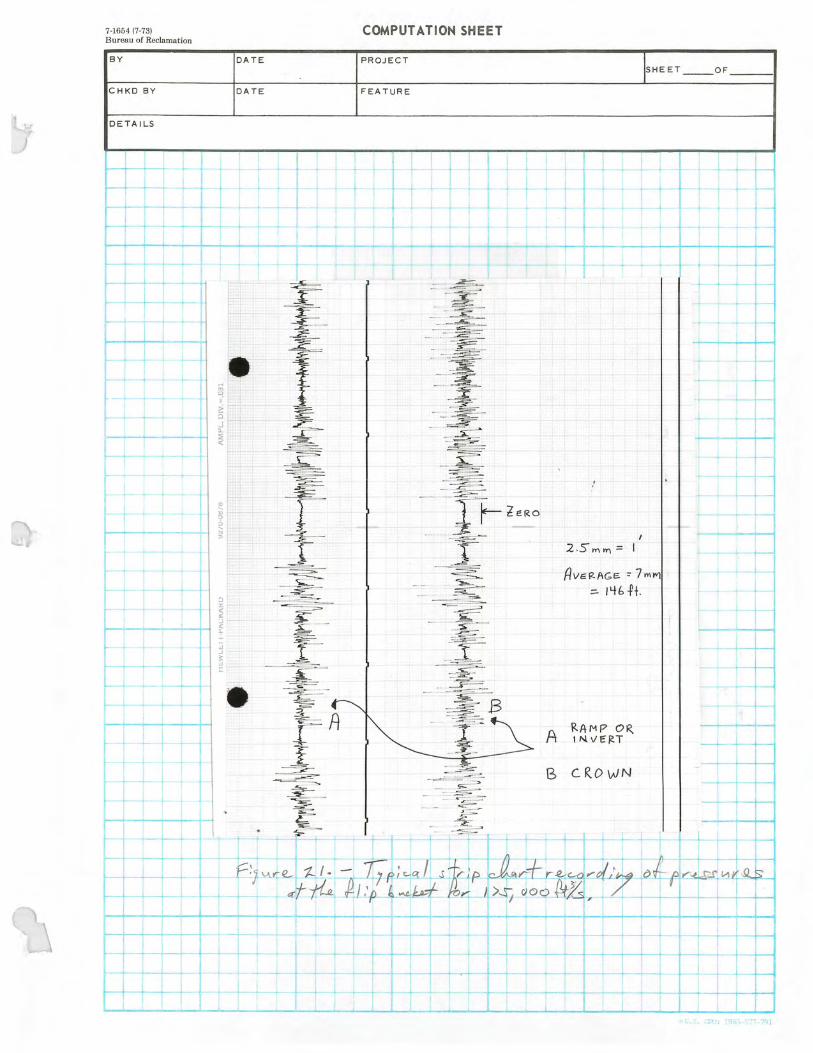
7-1654;7-73) COMPUTATION SHEET Bureau of Reclamation
BY DATE PROJECT SHEET OF
CHKD BY DATE FEATURE
DETAILS
I
ZERO
Pv-cg-AGF- = 7mm
-4-
4- 13 RAMP OR R. 1 14 V E RT
CROWN
19Y1,-577 791

7-1654 (7-73) Bureau of Reclamation
BY
CHKD BY
DETAILS
OF DATA POINTS = 8192 IMAXI VALUE = 3.5071b/in2 4.0
W .8 Cr D 5 Co W .4 x a
0 .2
N 0.0
J -.2
O z
-.8
- 1.0
y W U 2 W Cr Cr 7 U U O
LL O
Y U 2 W 7 O W Cr U-
0
0.0
0

io
m
K
77

T
LOCA TION OF 11°STRUME ~rATranr BOXES.-_
i h~' STATiDIJ ELEYAT(GiJ,
1- SEE__SECTION 'A=A 2 ` ''8+84.75 894.05 .. 3 f 10+15 i 741:30 4 10+80 675.08 5 20 + 05 ' 63.3.41
W.: l—r \ -alndftia es diversion tunnel star' rr;rrg. Stationing is located along the tunnel
2 -50 0 Dia, invert. f instrumentation boxes No. 2 thru lv'o. 5
El, 37 7 87 are located on the tunnel invert,
Sta. 9+00.40J
\ 1
i NevudG spillway ! i
49049'
h P.C. Sto. 10+I0.03 3 t
• _=~ i
$pringline f
3# f r
300 , a p r Spillway Tunnel 5ta. 12+09.70
Diversion tunnel Sta. Eq. 20-02.08 Instruments- i
E1. 533.42 l
ti0n bCX
SECTION A-A
a- .:a: ?..eTom: • rCE~ Irma'-..s. bu5s.• f f y., -̀
- .. .Ff st;- ~ •§f`.'. ~r`',,ip ~ *"`~~~' .d"~w~i " ~,. '-t-'~.'~ '~'>e `-~ A~~ _ ~ ~^l L}e~-' 1"•;~.' ~L7 R .

Z XIGN3ddd
HOOVER DAM - ARIZONA SPILLWAY
------------------------------------------------------------ ,
0 = 5000.0 CFS INITIAL DEPTH = 2.80 FT RUGOSITY = .001000 FT N = .0121
L .......................................................................... ENERGY.. DEPTH THICKNESS (STATION INVERT ELEV SLOPE DEPTH VELOCITY PIEZ GRADE LINE q AIR/q WATER PROFILE NORMAL CRITICAL BOUNDARY LAYER
FT FT FT FT/SEC FT FT FT FT FT
660.0 ............
1116.44 .................... ....... ...................................
2.800 .....- ......................................
34.843 2.134 1137.602 0.000 S2 .........................................................................................................................................................................................................
1.087 7.054 .858 725.0 1072.73 .6725 2.552 59.769 1.174 1129.897 0.000 S2 1.371 9.489 1.446 763.0 1037.93 .9158 .............................................................................................................. 3.611 71.862 .............. ----.................... 1.673 1122.367 0.000 S2 2.322 ..----- ................------...............................................---............................................................................................................. 11.446 1.782 802.5 994.55 1.0985 3.309 84.768 2,228 1111.073 0.000 S2 2.311 12.018 2.126 825.0 967.73 1.1915 3.172 90.676 2.039 1102.714 0.000 S2 2.297 12.190 2.322 867.8 916.77 1.1918 3.043 100.521
-•--------------- 1.956 1084.036 0.000 .......-- - .............................................................................----................-......................
S2 2.344 12.468 2.668 875.1 907.99 ..................................................•--•---.......................................-.....................---
1.1913 3.040 100.992 1.954 1080.495 0.000 S2 2.348 12.489 4",8- .....................................................................
2.727 900.4 877.87 1.1919 2.964 105.825 1.905 1067.672 0.000 S2 2.359 12.555 2.923 975.0 788.97 1.1917 2.758 117.734 1.773 1026.916 0.000 ...................................................................................................................................................................................................................................................... S2 2.359 12.554 2.758 1040.0 711.47 1.1918 2.642 125.497 1.698 982.180 0.000 S2 2.359 12.555 2.642 1078.5 675.27 .9410 2.627 126.544 7.662 956.451 0.000 S2 2.423 12.353 2.627 1117.0 .......................... 652.32 .5966 2.628 126.521 8.643 934.385 0.000 S2 2.599 11.854 2.628 .......................................................... 1164.0 636.36 .3394
6.......................................................................................... 2.654 124.627 8.774
i4.,-............................
910.431 -,-..........................................................................................................
0.000 S3 2.910 11.557 2.654 1211.7 631.08 .1108 2.712 120.730 8.697 888.743 0.000 S3 3.775 11.412 2.712 1250.0 630.95 .0034 2.750 118.274 2.750 ..... ............................................................................................................................................................................................................................................................................................................................................... 872.638 1.584 S3 8.956 11.210 2.750 1300.0 630.79 .0032 2.829 113.422 2.829 853.356 1.321 S3 9.090 11.207 2.829 1400.0 630.46 .0033 2.986 104.695 2.986 820.6681, .916 S3 9.019 11.209 2.986 1500•.0 630.13 .0033 3.141 97.112 3.141 794.353 .........................................................................................................................................................................................................................................................................................................................I .672 S3 9.019 11.210 3.141 ........ ................ . 1711.9 629.43 .0033 3.471 83.790 3.471 752.819 .367 S3 9.016 11.210 3.471 2212.1 627.79 .0033 4.272 61.664 4.272 697.011 .045 S3 9.033 11.210 4.272 2601:3 626.36 .0037 4.840 ........................................................................................... 51.330 4.840 676.203 0.000 S3 8.776 11.210 4.840 2622.9 626.98 -,0286 4.771 49.631
...................................••--...6 6.021 675.076 0.000 A3
............ 6......................................---............................................................................................................................. -1000.000 11.146 4.771
2644.6 628.87 -.0873 4.146 48.414 5.166 674.072 0.000 A3 -1000.000 10.237 4.146 2666.3 632.03 ............... •--............. ............. -.1458 ................................ 3.730 ................... 46.135 ...... ......................... 4.538 672.923 ....... ..................................... 0.000 . ......................................................................... A3 -1000.000 ... ............. ............. 9.504 ... ..... .. .......................... 3.730 I........................... 2687.9 636.50 -.2063 3.658 42.525 4.288 671.677 :••-0.000 A3 -1000.000 9.119 3.658 2707.3 644.40 -.4087 4.018 35.569 4.261 670.271 0:000 A3 -1000.000 0.143 3.747
ERROR IN DEPTH EXCEEDS 2. PERCENT PLEASE ADD INTERMEDIATE STATIONS AT 2698.4
............................................................................................................................................................................................. .
ENERGY GRADE LINE AT BEGINNING OF BOUNDARY LAYER
......... ....... t 150.64.3................... _.

HOOVER DAM - ARIZONA SPILLWAY ------------------------------------------------------------ ................................................................................................................................................................................................................................................................................................................................. ..... .
Q = 5000.0 CFS INITIAL DEPTH 2.80 FT RUGOSITY = .001000 FT N = .0121 .......................................................................................................... ..................•-•-----..........................................................................................------.............----................................................ ------.. .......................................... -
CAVITATION CHARACTERISTICS ............ .......................... ...................... . ........................................... : ................................................................................................................................ ................................................. : ................................................................ .... .
DAMAGE POTENTIAL
_ ........ ...... .................................._... SIGMA OF................REQUIRED.. CIRCULAR ARC - ...................-
90-DEGREE OFFSET ...........-......................................... ....-.................... . STATION FLOW UNIFORM CHAMFER TO 1/4-IN if2-IN 1-IN 1/4-IN 1%2-IN 1-TN
...........................................................
SIGMA
....................................................
ROUGHNESS
:
STOP
..........................
CAVITATION
.........
5-MM
..........................................................
10-MM 25-MM 5-MM
...................................................................................................
10-MM 25-MM
..................................... .._ _._..
660.00 1.819 .050 1 TO 1 .100E-01 .100E-01 .100E-01 .100E-01 .100E-01 .100E-0i 725.00 ....................................... I..........................--•-•-----......................... .602 1 .051 ........................................................... TO 5 .358E-01 .766E+00 ............................................................................................. .335E+01 .304E+00 .191E+01 ........................ .746E+01
--................................ ............ 763.00 .423 .051 1 TO 8 .207E+01 .764E+01 .243E+02 .360E+01
..................... .131E+02 .424E+02
802.49 .310 .052 1 TO 13 .134E+02 :416E+02 .121E+03 .188E+02 .601E+02 .182E+03 825.00 .269 .052 1 TO 16 .271E+02 .808E+02 .230E+03 .353E+02 .110E+03 .325E+03 867.76 .219 • .053 1 TO 21 .747E+02 .214E+03 .595E+03 .883E+02 .265E+03 .771E+03
._> 675.13 --->900.40
'..217 .053 1 TO 21 .777E+02 .223E+03 .618E+03 .908E+02 .272E+03 .792E+03 900.40 ....-• .........................................I...................... .198 .053 1 TO 24 ........................... .121E+03 .343E+03 ---........................................•---........ .943E+03 ....... ............ .135E+03 .................................. .402E+03 ............................. .116E+04 _...... .................. ,..... ._.... _ 975.00 .159 .054 1 TO 32 .350E+03 .967E+03 .262E+04 .386E+03 .112E+04 .318E+04 1040.03 .140 .054 1 TO 39 .652E+03 .1,78E+04 .480E+04 .717E+03 .206E+04 .581E+04 1078.50 .162 .054 1 TO 32 ................................................................................................................................................................................................................................................................................................................... .575E+03 .159E+04 .430E+04 .632E+03 .183Ei04 .521E+04 I ..... ..... ............. . . 1116.97 .166 .054 1 TO 31 .554E+03 .154E+04 .417E+04 .610E+03 .177E+04 .504E+04 1164.00 .172 .054 1 TO 29 .474E+03 .132E+04 .358E+04 .522E+03 .152E+04 .434E+04 1211.67 183 ............. 05 9 ......................... 1 . TO 27 345E+03 A64E+03 .263E+04 .381E+03 .112E+04. .320E+04
• 1250.00 '.163 .054 1 TO 31 .345E+03 .955E+03 .259E+04 .380E+03 .111E+04 .314E+04 1300.00 .178 .053 1 TO 28 .226E+03 .631E+03 .172E+04 .250E+03 .733E+03 .?IOE+04 1400.00 .210 ..-•-------------------•--........................----•----•---•--.........-----•----........................................... .053 1 TO 22 .993E+02 - .283E+03 .783E+03 .111E+03 .331E+03 .960E+03 ___ ..._ ._.. 1500.00 .245 .052 1 TO 18 449E+02 .132E+03
.............................------ .370E+03 .504E+02 .155E+03 .457E+03
1711.86 .332 .051 1 TO 12 .854E+01 .274E+02 .817E+02 .979E+01 .329E+02 .102E+03 2212.06 .627 ..049 1 TO 5 .100E-01 376E+p0 .......... .223E+01 .100E-01 .557E+00 .307E+01 2601.25• .919 .048 1 TO 3 .100E-01 .100E-01 .100E-01 .100E-01 .100E-01 .921E-02 2622.92 1.014 .048 1 TO 3 .100E-01 .100E-'01 .100E-01 .100E-01 .100E-01 .100E-01 2644.58 1.042 ........................................................•--•--...........-•-•--------.................................................. .049 1 TO _ 3 100E-01 .100E-01 .100E-01 .100E-01 .100E-01 .100E-01 _ . ---.......................................................... 2666.25 1.128 .049 1 TO .100E-01 .100E-01
- 2
--....----............................................................................................----......................................... .100E-01 .100E-01 .100E-01 .100E-01
2687.92 1.319 .049 1 TO 2 .100E-01 .100E-01 tOOE-01 .100E-01 .100E-01 .100E-01 2707.25 _.__ ................. ................................ ... ............ -...... 1.883 .048 1 TO 1 .100E-01 •---.....................------..............................................................................................................................................................----............................................................................ .100E-01 .100E-01 .100E-01 .100E-01 .100E-01 _

--------------
HOOVER ............................................................................................................................................................................................................................................................................................................................................................................... T ---------------------------------------------
DAM - ARIZONA SPILLWAY
.............. ............................................................................... Q = 10000.0 CFS ................ INITIAL ............................... DEPTH = 4.40 FT RUGOSITY - .001000 ----...-................................. .................................... .......................................................... FT N = .0125 .................... ........ ................... .......... .....
............................................................................ ........... ........... ...................... ........... ........... ........... ENERGY .............................. DEPTH ...................................-........-....................................-............ THICKNESS -.. STATION INVERT ELEV SLOPE bEPTH VELOCITY PIEZ
.................................................j-- GRADE LINE Q AIR/Q ,WATER PROFILE NORMAL CRITICAL BOUNDARV LAYER
FT FT FT FT/SEC FT FT FT FT FT ........................................
660.0 1116.44 ................................................................
.5190 4.400 ........................................
43.664 .................................... 3.043 1149.191
............ ................................................................... 0.000 S2
........................................... 1.580 10.986
........................................................... . .821
725.0 1072.73 .6725 4.487 66.023 1.712 1142.365 0.000 S2 2.126 14.533 1.396 763.0 1037.93 ......... .. .... ....................................... .9158 5.453 .........................._..... 78.200 2.290 1136.096 0.000 S2 3.243 16.279 •- -- ........................-.1 1.727 2 ..7 ....-............. 802.5 994.55 1.0985 5.055 90.691 3.403 1126.949 0.000 S2 3.230 ......... 17.158 2.067 825.0 967.73 1.1915 4.834 97.304 3.108 1120.316 0.000 S2 3.210 17.408 2.260 867.8 916.77 ................. 1.1918 4.628 108.247 2.975 1105.669 0.000 S2 3.278 17.824 2.601 _. 875.1 907.99 1.1913' 4.602 109.465 - .'54 1102.888 0.000 S2 3.283 17.851 2.659 900.4 877.87 1.1919 4.481 114.950 2.880 1092.776 0.000 S2 3.298 17.949 2.851 975.0 788.-97 1.1917...,. 4.134 129.444 2.657 1062.348 0.000 S2 3.298 17.952 3.375 1040.0 711.47 1.1918 3.962 137.808 2.547 1028.566 0.000 S2 3,298 17.952 3.809 1078.5 675.27 -9410 3.967 137.584 13.078 1009.442 0.000 S2 3.389 17.773 3.967 1117.0 652.32_ ...................................--- 5966 ............ 3.956 ................. ....._............ 138.149 14.859 ....................- 993.168 ........................ 0.000 -- • ...........
S2 .......... 3.638 ............... 17.055 .................... 3.956 ................. 1164.0 636.36 .3394 3.965 137.641 15.161 975.115 0.000 S3 4.076 16.620 3.965 1211.7 631.08 .1108 4.015 135.151 15.125 958.199 0.000 S3 5.302 16.409 4.015 1250.0 630.95 .0034 4.023 134.741 ..................................................... 4.023 945.077 .904 S3 _...................................................-................-----............................................... 12.789 16.009 .... 4.023 ......... ..... . 1300.0 630.79 .0032 4.098 131.143 4.098 928.649 .820 53 12.986 16.009 4.098 1400.0 630.46 .0033 4.246 124.432 4.246 899.172` .630 S3 12.881 16.010 4.2.46 1500.0 630.13 .0033 ....................................................................................................................... 4.394 118.314 ................. 4.394 873.623 ............................ . ....... . ........ .................. .496 ................ . ................................... S3 12.881 . ................... ........... 16.011 ... ....... . .................... 4.394 ... ... .......... ..... .... 1711.9 629.43 .0033 4.707 106.927 4.707 829.429 .297 S3 12.877 16.011 4.707 2212.1 627.79 .0033 5.456 86.101 5.456 759.871 .039 S3 12.903 16.011 5.456 2601.3 626.36 ................................... .0037 6.012 ... ...•------........................................................................ 6.012 74.715 ........................................................................................ 727.722 0.000 S3 12.523 -•-•----•---.............----...................................---•--..................................................._. 16.010 6.012 2622.9 626.98 -.0286 5.959 72.381 9.284 725.751 0.000 A3 -1000.000 16.1QO 5-959 2644.6 628.87 -.0873 5.229 71.475 8.057 724.186 0.000 A3 -1000.000 15.051 5.229 2666.3 632.03 -.1458 4.687 69.846 7.076 722.433 .....................................................................................................................•----............................--..........................................................................................................................................................I....................... 0.000 A3 -1000.000 14.213 4.687
.
2687.9 636.50 -.2063 4.468 67.354 6.536 720.525 "••0.000 A3 -1000.000 13.810 4.468 2707.3
......................... 644.40
.................................. ................................................................................ -.4087 4.477 63.109
- ..................................... 6.045 718.472
............ ...................... 0'.000
........................................... A3 ..............................................................
-1000.000' 14.109 ...........................................
4.477 . -
ENERGY GRADE LINE AT BEGINNING OF BOUNDARY LAYER ...................................................... -- ....... ... .................. ..................................... 1160.743
CAVITATION CHARACTERISTICS
DAMAGE POTENTIAL „_--_..- .................... SIGMA OF .. . . .......................... REQUIRED ....................................................... CIRCULAR ARC 90-DEGREE OFFSET
STATION FLOW UNIFORM CHAMFER TO 1/4-IN 1f2-IN 1-IN 1 / 4-1N 1/i D4 ........ 1-IN
................................................................................................................
SIGMA ROUGHNESS STOP CAVITATION
......................................................................................................................................................
5-MM 10-MM 25-MM 5-MM
........... - ................
10-MM 25-MM ..................................................... ........... ...
660.00 1.189 .046 1 TO 2 .100E-01 .IQOE-01 .100E=01 .100E-01 .100E-01 .123E-01 725.00 .501 .047 1 TO 7 ..................................................................................................................................................................................................................................................................................................................................................................... .658E+00 .305E+01 .106E+02 .154E+01 .633E+01 .217E+02 763.00 .364 .047 1 TO 10 .582E+01 ..192E+02 .578E+02 .939E+01 .314E+02 .975E+02 802.49 .280 .048 1 TO 15 .266E+02 .799E+02 .228E+03 .364E+02 .114E+03 .338E+03 II25.00 .241 .048 ...,. .. 1 TO 18 ........................ .545E+02 158E+03 .444E+03 .696E+02 .211E+03 .619E+03 _. .,,....... _ ............................~ ...................... 867.76
,j ... .194 .049 1 TO 25 .152E+03 .429E+03 .118E+04 .177E+03 .522E+03 .150E+04
875.13 .199 .049 1 TO 25 .169E+03 .474E+03• .130E+04 .194E+03 .571E+03 .164E404 900.40 .172 .049 1 TO 29 _......_....._._._.._ ....................................................................................................................................................................................-............................................................................................................................ .266E+03 .742E+03 .202E+04 .293E+03 .856E+03 .244E+04 975.00 .135 .050 1 TO 41 .792E+03 .217E+04 .582E+04 .788E+03 .226E+0.4 .638E+04 1040.03 .119 .050 1 TO 49 .138E+04 .373E+04 .998E+04 .128E+04 .366E+04 .103E+05 1078.50 .156 ......... .... .050. .......................... ......-.. 1 TO 34 .962E+03 .265E+04 .717E+04' .883E+03 .256E+04 .728E+04 .................................................. ........... . 1116.97 . 161 .050 1 TO
.......-....-...........................-...........+..
32 .951....
E p3.. ...........
2... . 63
..... E... i .... 0..4..........
7....
1....... -.........
...
.2E+0....
4 8.. .........
+..............
.....25...
4E..
73E03 +0....
4..
.723..E+04
1164.00 .163 .050 1 TO 32 .907E+03 .251E+04 .680E+04 .833E+03 .243E+04 .691E+04 1211 . 67 .169 .................. ...................................................................................................................................•---........---............---............................ .050 1 TO 30 .756E+03 .210E+04 ........ .570E+04 ............. ............................ .694E+03 .203E+04 ..... ......... ....................................... .580E+04 ..... ......................... .. ........ ... -. . 1250.00 .130 .050 1 TO 43 102E+04 .280E+04 .750E+04 .943E+03 .270E+04 .762E+04 1300.00 .138 .050 1 TO 40 .783E+03 .215E+04 .577E+04 .721E+03 .208E+04 .588E+04 1400.00 .154 .049 1 TO 34 .464E+03 .128E+04 .347E+04 .428E+03 .124E+04 .354E+04 1500.00.........;.1.7.' ..................049...................... 1 TO 2s
.2795+03 .777E+p3 .212E+04.......
.257E+03....-•
.756E+03..... .217E+04.-.................................
1711.86 .211 .049 1 TO 22 .981E+02 .281E+03 .780E+03 .909E+02 .275E+03 .802E+03 ...................................
2212.06 .332 .047 1 12 .874E+01 .284E+02 .851E+02 TO .......................................................................................................................................................................................I......................_..-.. .810E+01 .280E+02 .886E+02 2601.25 .447 .046 1 TO 8 .121E+01 .525F#0.1 .179E+02 .110E+01 .521E+01 .188E+02 2622.92 .517 .046 1 TO 6 .404E+00 .275E401 *.106E+02 .358E+00 .278E+01' .113E+02 2644.58 .514 .047 1 TO 6 .419E+00 .270E+01 .103E+02 .430E+00 .294E+01 .117E+02 2666.25 .526 .047 1 TO 6 .312E+00 .222E+0t .862E+01 .365E+00 .260E+01 .104E+02 2687.92 .558 .047 1 TO 6 .105E+00 .139E+01 .585E+01 .157E+00 .172E+01 .741E4-01 2707.25 ... ...................................... .627 .047 1-- ........... 1 TO 5 .100E-01 .......... ..........-..........-.........................---...................................................................................................................................-----..................................................._._ .444E+0U .260E+01 .100E-01 .624E+00 .347E+01

.............................................................................................................................................. ENERGY DEPTH ............................................................................................................ THICKNESS ....................... Sli1TI0N INVERT ELEV SLOPE DEPTH VELOCITY PIE2 GRADE LINE 0 AIR j0 WATER PROFILE NORMAL CRITICAL BOUNDARY LAYER
FT FT FT FT/SEC FT FT FT FT FT
660.0 ..........................................
1116.44 .5190 6.200, ................................--------------................................................_...........................................
45.691 4.174 1153.087 0.000 S2 -- ---.............................--•-----.......................................................................--------....................._.. 2.170 14.173 .813
725.0 1072.73 .6725 6.361 67.970 2.261 1146.854 0.000 S2 2.753 18.511 1.385 763.0 1037.93 .9158 7.064 80.261 2.859 1141.292 ............................................................................... 0.000 S2 3.948 ........... .................................................................................................................................... 20.029 1.715 802.5 994.55 1.0985 6.563 92.751 4.418 1133.338 0.000 S2 3.933 21.168 2.053 825.0 967.73 1.1915 6.267 99.696 4.029 1127.607 0.000 S2 3.909 21.480 2.245
.......8,67.8 916.77 1.1918 5.991 111.199 3.851 1115.093 0.000 S2 3.993 22.010 ......................................................... 2.584 875.1 907.99 1.1913 5.948 112.705 3.824
. ....................................................................................................................................................................................................................................§6......... 1112.724 0.000 S2 3.999
i.,
22.045 2.642 900.4 877.87 1.1919 5.785 118.548 3.718 1104.115 0.000 S2 4.018 22.169 2.833 975.0 .-.788.97 1.1917 5.310 134.401 ......................... 3.413 1079.604 0.000 .............................................................................................................................................................................................................. S2 4.019 22.168 3.353 ................. 1040.0 711.47 1.1918 5.054 144.482 3.249 1051.794 0.000 S2 4.019 22.172 3.783 1078.5 675.27 .9410 5.051 144.628 17.537 1035.802 0.000 S2 4.130 22.049 4.003 1117.0 652.32 .5966 5.028 145.593 19.952 1022.096 0.000 S2 4.434 21.159 4.186 1164.0 636.36 3394 5.037
............... 6.... d.._.................44.................................................................................---......................-6................................... 145.188 20.443 1006.819 0.000 S2
6..................................................................................................................... 4.972 20.614 4.387
1211.7 631.08 .1108 5.094 142.844 20.496 992.446 0.000 S3 6.461 20.345 4.579 1250..0 630..95 :0034 5.080 143.402 5.080 981.158 .543 S3 ................................................................................................................................................,............... 15.858 19.757 4.731 1300.0 630.79 .0032 5.163 140.027
...................................................................6 5.163 966.825 .505 S3 16.109 19.757 4.928
1400.0 630.46 .0033 5.317 134.146 5.317 940.6561- .393 S3 15.976 19.758 5.316. 1500.0 630.13 .0033 5.476 128.452 5.476 917.429 .310 S3 ............---•--•----.............................................................................................................................................................. 15.976 19.759 5.476 1711.9 - 629.43 .0033 .... ........................................ib... 5.781
6.............. 118.662 5.781 875.720 .180 53 15.970 19.759 5.781
2212.1 627.79 .0033 6.507 99.855 6.506 804.609 0.000 S3 16.004 19.759 6.507 2601.3 626.36 .0037 .................. 7.053 88.790 ..................................... 7.053 768.073 ............................... 0.000 S3 ....................-•---------........---......................................... 15.519 19.756 7.053 .................................. 2622.9 626.98 -.0286 7.031 85.901 12.558 • ~ 765.577 0.000 A3 -1000.000
j-.......... 20.003 7.03 1
2644.6 628.87 -.0873 .6.234 85.164 11.029 763.783 0.000 A3 -1000.000 18.871 6.234 2666.3 632.,03 -.1458 5.625 83.810 ........................................................................................................................... 9.777 761.785 0.000 A3 ................... I............................---........................----.............................................. -1000.000 18.015 5.625 .............. ......... 2687.9 636.50 -.2063 5.356 81.712 9.057 759.602 :•0.000 A3 -1000.000 17.679 5.356 2707.3
.................. 644.40
........ .................................................... -.4087
...................... 5.320
................... 78.207
..................................... 8.393 757.266
......•-•---------....................................----------........................•.................. 0:000 A3 -1000.000
............................... 16.162
.- ........................... 5.320
...........................

__..,......_ _.._..._......._....-....__.......... HOOVER
------------------------------------------------------------ - ._ .................................._...,........................................................................................................................................._..................................................................... DAM - ARIZONA SPILLWAY
_... .
.............................................. Q __......._._ = 15000.0 CFS _ . . . ...................._ INITIAL ._........................................ DEPTH = 6.20 FT ..._.............. RUGOSITY __..........._......_.................. = .001000 FT N = --.............................................................. .0128 _... ..
............................................................... ..............................___ ............................................................................................................................------•---..................._......................---- CAVITATION CHARACTERISTICS ...............:...._............................................._.._
DAMAGE POTENTIAL SIGMA OF REQUIRED ---......................................---............................................. CIRCULAR ARC ................................_ - _ .._.-. 90-DEGREE OFFSET ...... ........ I ..._........ ............_.................................................- ......................................................•---------.......----•----•---•----...................
STATION FLOW UNIFORM CHAMFER TO t/4-IN 1/2-IN 1-IN 1/4-IN 1%2-IN 1-IN
....... --•- ............................................
SIGMA
.... ... ........._
ROUGHNESS
_. . ..... .....-....- STOP
- ......... CAVITATION
....... 5-MM
............ 10-MM
....- 25-MM
................ 5-MM 10-MM
............................................................................... 25-MM
660.00 1.121 .044 1 TO 2 .100E-Oi 100E-01 .100E-01 .100E-01 .100E-01 .149E+0O 725.00 .481 .044 .........................................................................................._.... 1 TO 7 .997E+0O .423E+01 .143E+02 .218E+01 .854E+01 .286E+02 __..._ .. __... 763.00 .351 .045 1 TO 11 .764E+01 :247E+02
.................................'7"6'..'E+'..........................'0"'....................................1"2*1'E
+'................._..'
4-0............................_..
.737E+02 .121E+02 .401E-02 .123E+03 802.49 .275 .046 1 TO 15 .324E+02 .965E+02 .275E+03 .440E+02 .136E+03 .405E+03 825.00 .....................................................- .236 ---............ .................. .046 .................................... 1 -- TO 19 .674E+02 ............................................----..............................................--- .195E+03 .545E+03 .855E+02 ................._................ -- • .259E+03 ---.... ..... ............................. .755E+03 ......... _..............._........... 867.76 .189 .046 1 TO 26 .193E+03 .541E+03 .148E+04 .222E+03 .655E+03 .188E+04 875.13 .184 .047 1 TO 27 .218E+03 .611E+03. 167E+04 .249E+03 .730E+03 .209E+04 900.40 .166 ............................................................................................................................................................ .047 1 TO 31 .350E+03 .971E+03 .264E+04 .382E+03 i11E+04 .316E+04 975.00 .128 .047 1 TO 4A 111E+64 .302E+p4 .810E+04 .109E+04 .313E+04 .880E+04 1040.03 .111 .048 1 TO 54 .211E+04 .570E+04 .152E+05 i95E+04 .553E+04 .155E+05 1078.50 .155 .048 1 TO 34 .138E+04 ...........................................................--...........----•----------..........................................._......................................................................................................................................................._.......................................... .381E+04 .103E+05 .125E+04 .361E+04 .103E+05 _.. 1116.97
- .160 .048 1 TO 32 .136E+04 .376E+04 .102E+05 .121E+04 .351E+04 .998E+04
1164.00 .162 .048 1 TO 32 ,.129E+04 .356E+04 .965E+04 .112E+04 .326E+04 .930E+04 1211.67 ................. -................ -....... ---- ............................ .168 .048 1 - .......................................................................................................... TO 30 .108E+04 - ... --- ........... .300E+04 -...... ........ ....................... .815E+04' ..... ....... .929E+03 -.......... ----.... .272E+04 - ............ ................... .776E+04 ..... -... ..... I............................. 1250.00 .118 .048 1 TO 49 170E+04 .462E+04 .124E+05 .145E+04 .414E+04 .116E+05 1300.00 .125 .048 1 TO 46 .134E+04 .363E+04 .974E+04 .113E+04 .323E+04 .909E+04 1400 00 ...................................... .136 .047 1 TO 41 .859E+03 .235E+04 .633E+04 .713E+p3 --..................,.........................---........................................................................................................................................................... .206E+04 .582E+04 1500.00 .149 .047 1 TO 36 .557E+03 .154E+04 .415E+04 .462E+03 .134E+04 .382E+04 1711.86 .176 .047 1 TO 28 .249E403 .698E-03 .191E-f•04 .207E+03 .612E+03 .176E+04 2212.06 .254 .046 1 TO 17 .401E+02 .119E+03 .339E+03 .331E+02 .105E+03 .315E+03 2601.25 .325 .045 1 TO
.......................................................................................................................................................................................................'0.3..........",4. 12 .104E+02 .335E*02 .100E+03 .843E+0i
_................................................................. .294E+p2 ...
........................... ........... .933E+02
2622.92 .395 .045 1 TO 9 .500E+01 .183E+02 .580E+02 .401E+0t .161E+02 .545E+02 2644.58 ...................................................... ........ .389 .045 1 ...............................................-----..............................---............................. TO 9 .519E+pi 186E+02 .585E+02 -.............................................................................................. .447E+01 .173E+02 .580E+02 -............................................................................ . 2666.25 .390 .046 1 TO 9 .478E+Oi 171E+02 .538E+02 .437E+0i .168E+02 .559E+02 2687.92 .403 .046 1 TO 9 .366E+01 .135E+02 .431E+02 .347E+01 .137E+02 .461E+02 2707.25 - ......................................................... .433 .045 1 ..............................................................................-•. TO 8 .209E+01 .839E+01 .278E+02 --....................................................................................................................................................................... .201E+01 .867E+01 .302E+02
...........................................................•--................................................................--•---...................................... ....... .......................................... ................................ . ............ .................. .
........................................ . .................. ................................................................................................ .................... ................................................... ........................................ .:.............. .
• ............:................................................................................ •-•---................................ ..... ...................... ........ _ _...__
.............................................................................................. --- ........................................._............................................................................................ _ _.... .

HOOVER DAM 7 ARIZONA SPILLWAY ----------------------------------- - ----------------------- ................. ................................. .................................................•----..........: - ................................................................................................................ •---................................................................................................I.... .......... I......... ......:.'
0 - 20000.0 CFS INITIAL DEPTH = 7.40 FT RUGOSITY - .001000 FT N = .0129 ...................................................... ........... ...........................................................................................I......................... ----..................................................................... ----........................................ .............I..................... ..................
ENERGY DEPTH THICKNESS STATION INVERT ELEV SLOPE DEPTH VELOCITY PIEZ GRADE LINE 0 AI -& WATER PROFILE NORMAL CRITICAL BOUNDARY LAYER
FT FT FT FT/SEC FT FT FT FT FT
660.0 .................. ..................................................................................
1116.44 .5190 7.400 ................................. .................
50.471 4.634 , ...................................................
1160.674 .................................................
0.000 S2 2.604 : .................................................................................................................
16.934 ..
.797 725.0 1072.73 .6725 7.893 71.460 2.414 1154.530 0.000 S2 3.308 21.890 1.364 763.0 ... ...................... 1037.93 .9158 8.387 I ....................................................................................................... 83.320 3.182 ............ ................................ 1149.233 0.000 S2 4.542 ---•----•---........I....I................ 23.215 -........................... 1.691 802.5 994.55 1.0985 7.839 95.436 5.277
........................ 1141.832
---..................................... 0.000 S2 4.525 24.590
..........-......... ..... ..... 2.027
825.0 967.73 1.1915 7.493 102.421 4.817 1136.526 0.000 S2 4.497 24.956 2.218 667.8 916.77 ................................................... 1.1918 •----...........i9....................-.....7 7.173 114.038 4.611 .........- - .......................... 1125.084 1 4...................?-.!?! -------0 0.000 ............. S2 ....... ... 4.596 25.583 2.555 .........................-....-...-.................................................... 875.1 907.99 1.1913 7.118 115.662 4.577 1122.931 0.000 S2 4.603 25.625 2.612 900.4 877.87 1.1919 6.924 121.628 4.450 1115.124 0.000 S2 4.626 25.771 2.803 975.0. 1.1917 788.97 ........................................................................................... 6.346 138.077 4.079 1093.950 .......................................................................... 0.000 ............................... S2 • 4.626 ......................................... 25.770 3.320 .................................................... 1040.0 711.47 1.1918 6.022 149.050 3.871 1069.753 0.000 S2 4.626 25.773 3.747 1078.5 675.27 .9410 6.019 149.159 21.663 1055.777 0.000 S2 4.754 25.721 3.966 1117.0 652.32 .................................................................. .5966 5.983 .... ................................... 150.464 24.647 ......................................................................... 1043.769 0.000 S2 .............................................................. 5.107 24.687 --................................... 4.148
I ... .............. 1164.0 636.36 - 3394 5.982 150.509 25.268 1030.289 0.000 S2 5.730 24.042 4.348 1211.7 631.08 .1108 6.034 148.610 25.364 1017.491 0.000 S3 7.481 23.733 4.538 1250.0 630.95 .0034 5.989 150.245 5.989 1007.288 ............................................................................................................................................................................................................................................................................................................... .338 S3 18.558 22.956 4.689 ........................... 1300.0 630.79 .0032 6.073 147.242 6.073 994.143 .320 S3 18.862 22.956 4.883 1400.0 630.46 .0033 6.227 141.952 6.227 969.815E .241 S3 18.700 22.957 5.267 1500.0 630.13 ... ............................. ...... ............ .0033 : ......... .... ............................ 6.387 . .............. 136.786 .............. ......... 6.387 ............ . .............. 947.837 ................. .. ......... ........... .182 . ................. ............................................... S3 18.700 22.957 ................................. 5.646 ... . ............................ ................... . 1711.9 629.43 .0033 6.709 127.341 6.708 907.609 .084 S3 18.694 22.958 6.430 2212.1 627.79 .0033 7.464 .109.044 7.464 836.854 0.000 S3 18.735 22.958 7.464 2601.3 626.36 ................. ................... .......... .0037 ............................... 8.028 ...................................... 98.126 8.028 ..................... 798.854 0.000 ... _..................................................................---...............................-.................................................................................................. S3 18.151 22.956 8.028 2622.9 626.98 -.0286 8.044 94.735 15.735 796.011 0.000 A3 -1000.000 23.355 8.044_ 2644.6 628.87 -.0873 7.193 94.125 13.958 794.153 0.000 A3 -1000.000 22.200 7.193 2666.3 .................. ................... 632.03 .•--....-------- .......... -.1458 6.537 .............................................................................................. 92.949 12.488 792.088
I...................... 0.000
............................................................................................ A3 -1000.000 21.397 6.537 ........................---.............................------.............................
2687.9 636.50 -.2063 6.241 91.079 11.630 789.821 0.000 A3 -1000.000 21.045 6.241 2707.3
................................................... 644.40
: ................ -.4087
. .................................... 6.208
.. ........................................................................ 87.950 10.865 787.389
. ............... - ................................................................. ' . 01000 A3
... -1000.000
......... . .................................. 21.508
.............................. 6.208
... ............. ....... ....
ENERGY GRADE LINE AT BEGINNING OF BOUNDARY LAYER 1171.071
........................................................................................................................................................................................................................................................,........------••--•----..........................----•-.......................:..................I -----............
..............................................................................................................................................--.........................................................................................................................................................................................................................
.................. .. ... .............................•--••----••-•---.....................----------.................................-----•--•-----......................................................................................................... --------------..................................................... ... ............ ......................
..............................................................................................•--------.....----.............................--•--------......................-•-•-•-•-•--.........................................................................---•------....................................--............................... ...................................................
...................................................................................................................................................................................................................................................................................................................................................................... .

DAMAGE POTENTIAL SIGMA OF REQUIRED CIRCULAR ARC 90-DEGREE .......................................... . OFFSET
STATION FLOW UNIFORM CHAMFER TO 1%4-IN 1%2-IN 1-IN_
1%4-IN 1~2-IN _........
............. .........___..
i-IN
I SIGMA ROUGHNESS STOP CAVITATION 5-MM 10-MM 25-MM 5-MM 10-MM 25-MM
660.00 .930 .043 1 TO 3 .100E-01 .100E-01 .138E+00 .100E-01 .649E-01 .118E+01 725.00 .437 .043 1 TO 8 .205E+01 .765E+01 .245E+02 .409E+01 .148E+02 .477E+02 763.00 .329 .044 1 TO 12 .116E+02 ............................3............................................................................................................................................................................................................................................,.............................................._....
363E+02 .107E+03 .180E+02 .581E+02 .177E+03 802.49 .266 .044 1 TO 16 .423E+02 .125E+03 .354E+03 .571E+02 .176E+03 .519E+03 825.00 .228 .045 1 TO ...................................................................................................................................................................................................................................................................................................................... 20 .863E+02 .248E+03 .691E+03 .109E+03 .328E+03 .953E+03 .......................... . 867,76 .183 .045 1 TO 27 .241E+03 .675E+03 .184E+04 .277E+03 813E+03 .233E+04 875.13 .17$, .045 1 TO 28 .275E+03 .768E+03. .209E+04 .312E+03 .913E+03 .261E+04 900.40 .. . ....................................................... .. .161 --.............................................•---•-............................................•. .045 1 TO 32 .439E+03 --................ .............................. .121E+04 ..... -. .329E+04 .477E+03 .139E+04 .394E+04 -- .......... •................_._.........._ - .. . 975.00 .124 .046 1 TO 46 .141E+04 .383E+04 .102E+05
................................................................ .138E+04 .394E+0.4 .111E+05
1040.03 .106 .046 1 TO 58 .278E+04 .751E+04 .200E+05 .255E+04 .724E+04 .202E+05 .157 .046 1 TO ...................................... 1078.50 33 .169E+04 .466E+04 .126E+05 .151E+04 .439E4•04 ....... .125E+05 .................... _
1116.97 .163 .046 1 TO 31 .169E+04 .466E+04 .126E+05 .148E+04 .431E+04 .123E+05 1164.00 .165 .046 1 TO 31 .164E+04 .453E+04 .123E+05 .141E+04 .412E+04. .117E-05 1211.67 ............ .169 ....... .................. .046 ....... ............................ . 1 TO 30 ...................................... .142E+04 ........ - ................................ .395E+04 .107E+05 ........ ............................. .121E+04 ....... .......... ... ................. .355E+04 . ............. ............... .101E+05 , ......................................... .. _. 1250.00 .111 .046 1 TO 55 .258E+04 .699E+04 .186E+05 .218E+04 .619E+04 .174E+05 1300.00 .115 .046 1 TO 51 .210E+04 .569E+04 .152E+05 .175E+04 .500E+04 .140E+05 1400.00 .........x.35 .125 ..................046........................1...To....4.1 .046 1 TO 46 .144E+04 .392E+04 .105E+05 .118E+04 .338E+04 .953E+04 1500.00 .982E+03....... 269E+04 .723E+04........ 792E+03.
..... 228E+04
........ 646E+04
.....................................
1711.86 .157 .046 1 TO 33 .466E+03 .129E+04 .350E+04 .364E+03 .107E+04 .305E+04 2212.06 __......_.__....._.._ .....................................I............ .218 ............- .045 1 TO 21 .919E+02 _..................................................................................................................-................. .265E+03 .741E+03 .703E+02 .216E+03 ..................,..... .637E+03 2601.25 .273 .044 1 TO 15 .289E+02 .877E+02 .253E+03 .218E+02 - .711E+02 .217E+03 2622.92 .348 .044 1 TO 11 .136E+02 .454E+02 '.138E+03 .101E+02 .367E+02' .119E+03 2644.58 .340 .044 ....................... 1 TO -•-----•--- 11
................... .144E+02 .472E+02 .142E+03 --............. .113E+02 .402E+02 .129E+03 ..................... .
2666.25 .337 .044 1 TO 11 ................... .138E+02 ........
................*---------------- .452E+02 .136E+03
--............................................... .115E+02 ................. A02E+02 .128E+03
2687.92 .344 .044 1 TO 11 .116E+02 .382E+02 .115E+03 .985E+01 .349E+02 .112E+03 2707.25
..............................................................................................
........................................... ..............................................................................--
.............. .....................................................................................................
.363
...................................................................................................................................................................................
.044
.................................................
1 TO 10
............... .................
.................................................................................................................................................................................................................................................................................................................................
.792E+01
...............................................................................
.270E+02 .................................................---•--.........--...........---------................................._............................................................................ .828E+02
.................................•-•---.......................................----...........................................................................................-----.........-•----.......................:......................
...........................................................................................................................................:......:........................................
.681E+01
.......... ........................................................................
.250E+02 .813E+02 -__.
.............................
...................................

HOOVER DAM - ARIZONA SPILLWAY ----=------------------------------------------------------- ..................... ....................... .......................................... _................. ... ........................... ....!.._....................................................................................._........__ ... ............................................................................ ... _........ ...... .. _ _.. ....
..............................................................•...Q........50000..0_..CFS ,-- ..__ INITIAL_.DEPTH 14.80 FT RUGOSITY = .001000 FT N = .0135 ...
ENERGY DEPTH THICKNESS STATION INVERT ELEV SLDPE DEPTH VELOCITY PIE2 GRADE LINE q AIR/.6 WATER PROFILE NORMAL CRITICAL BOUNDARY LAYER
FT FT FT FT/SEC FT FT FT FT FT
- ...... 660.0 1116.44
...... ............................."--.------•--------................................ .5190 14.800, 59.011 7.852 1178.380
--......................---•-•---------.........---....................................----.....-----...........-•-•----............................---......................................................_.................._................_ 0.000 S2 4.670 29.291 .773
725.0 1072.73 .6725 16.024_ 78.953 3.056 1172.607 0.000 S2 5.959 36.400 1.328 763.0 1037.93 -- ---------------•--...................................._........---...... .9158 15.073 ............... ............ 89.833 .......... ...........------......................... 4.858 1168.184 ................................................... 0.000 S2 ........................................------................................................................ 7.125 37.234 1.650 ........ I .... ................ ....... 802.5 994.55 1.0985 14.288 100.905 9.618 1162.460 0.000 S2 7.106 39.614 1.982 825.0 967.73 1.1915 13.659 108.089 8.781 1158.276 0.000 S2 7.062 40.166 2.171 867.8 916.77 1.1918 13.113 120.069 8.429 1149.623 0.000 S2 7.230 40.847 2_-505 ............. 875..x
.................907.99
............1.... .................................................1.00021 .925"
8.358...........- 1148.025
... ..........- "0.00
0...-.....................S 2..............7. 242
.........40.87.'......................2.562
900.4 877.87 1.1919 12.640 128.225 8.124 1142.293 0.000 S2 7.281 40.974 2.751 975.0 788.97 1.191.7 11.520 146.190 7.405 1129.803 0.000 S2 7.281 40.972 3.262 ................ 1040.0
.................7.1....g7............1...1s.1.8...........10.848
............159.23.3...........6.973.
.............1 1
15. 3.15................. -.0.000
.........................52..............7 .28.1.
........40. 978......................3
J. 683 1078.5 675.27 .9410 10.931 157.512 42.039 1106.997 0.000 S2 7.487 41.098 3.899 1.117.0" """""--"""..,652.._32" .5966" 10.838 159.445 47.822 1099.930 0.000 S2 8.054 39.755 4.080 " 1164.0 636.36 .3394 10.781 160.638 49.154 1091.883
...................:...........................................................................................................................................................................46......................... 0.000 S2 9.062 3$.865 4.277
1211.7 631.08 .1108 10.814 159.940 49.533 1084.079 0.000 S3 11.929 38.421 4.465
1250.0-"."_. "-.-•"""-630.95 .0034 10. 528 166. 168 10.528 1077. 539 0.000 S3 32.457 36.915 612 4.612 ... ..... ............... 1300.0 630.79 .0032 10.611 164.316 10.611
..................................................................................................................................-..........................---..........................j..................................... 1068.698 0.000 53 33.151 36.915 4.802
1400.0 630.46 .0033 10.766 160.960 10.766 1051.7641- 0.000 S3 32.780 36.915 5.176 1500•.0 630.13 .0033 10.926 157.623 10.926 1035.764 0.000 .................................................................•--....................................................------........---........................................-............................................................................................. S3 32.780 36.915 5.545
1711.9 629.43 .0033 11.252 151.157 11.252 1004.610 0.000 S3 32.765 36.916 6.302 2212.1 627.79 .0033 12.023 137.607 12.023 943.071 0.000 S3 32.857 36.916 8.007
2601.3 626.36 .0037 12.651 128.067 12.651 904.979 0.000 ................................................................................................................................................................................................................................................................................... S3 31.548 36.913 9.300
2622.9 626.98 -.0286 13.004 121.388 32.570 900.719 0.000 A3 -1000.000 37.995 9.372'
2644.6 628.87 -.0873 11.966 121.273 29.859 898.965 0.000 A3 -1000.000 36.766 9.445
2666.3 632.03 -.1458 ................ 11.241 ..... --------... 119.916 ...... 27.762 896.996 0.000 A3 -1000.000 ,,......;........................................................................................................_...................._....._ 35.581 9.518
2687.9 636.50 ......-
-.2063 10.985 117.988 26.639 894.808 .0.000 A3 -1000.000 26.274 9.592
2707.3 644.40 -.4087 11.332 115.202
--•• ............................................................................................................•--------•-"-----....---.........-..........--"---..................................................................................----•-................................................................................
26.173 892.365 6.000 A3 -1000.000' 29.478 9.663
.......................... _ -

HOOVER DAM - ARIZONA SPILLWAY -- - - - - - - - - - - - - •r - - - - - - - - - - - - - - - - - - - - - - - - - - - - - - - - - - - - - - - - - - - - - .....................................................................................................................................................................................................................................................................................................
Q...'...50000.0.. CFS........INITIAL..DEPTH...=....14: 80...FT.........RUGOSITY...=....001000...FT.........N...`......0135
CAVITATION CHARACTERISTICS
DAMAGE POTENTIAL SIGMA OF REQUIRED CIRCULAR ARC 90-DEGREE OFFSET
STATION FLOW ..............
UNIFORM................
CHAMFER...Tp....................t/4-IN..........1~2
-IN...........
1-IN...................
1/4-IN............1
f 2-IN..........i._ I.N_. .
.....................................................................................................................................•-• SIGMA ROUGHNESS STOP CAVITATION 5-MM 10-MM 25-MM 5-MM
....................................--•--.------.........................................................................----------........................................................................................... 10-MM 25-MM
660.00 .740 .039 1 TO 4 .100E-01 .298E+00 .223E+b1 .119E+00 .169E+01 .745E+01 725.00 .................................................. ..••---••-------. .364 .039 1 ----..................-...... TO 10 .694E+01 .226E+02 .679E+02 .125E+02 .411E+02 .126E+03 763.00 .296 -•--•-............................
.040 1 TO 14 .246E+02 ..743E+02 .214E+03 .._........................................................................-----•....2"1'........................................................._........-.----.........................._..............................
.371E+02 .116E+03 .346E+03 802.49 .265 .040 1 TO 16 .640E+02 .189E+03 .533E+03 .855E+02 .262E+03 .773E+03 825.00 .227 .041 1 ..........................................................•--................................................................................................................................................................................................................; TO 20 .129E+03 .371E+03 .103E+04 .162E+03 .485E+03 .141E+04 .................................................................................. 867.76 .18Q .041 1 TO 27 .353E+03 .987E+03 .269E+04 .403Ef03 .118E+04 .337E+04 875.13 .177 .041 1 TO 28 .408E+03 .114E+04, .310E+04 .459E+03 .134E+04 .383E+04 900 40 .159 .041 1 ..............................................---:......r.-•--•---.........................------......---..................................----........................................................................................................I................I............ TO 33 .654E+03 .180E+04 .488E+04 .704E+03 .204E+04 ............................. .579E+04 _..... ..... ................... _ 975.00 .120 .042 1 TO 48 .220E+04 .596E+04 .159E+05 .213E+04 .608E+04 .170E+05 1040.03 .101 .042 1 TO 62 .475E+04 .128E+05 .339E+05 .430E+04 .122E+05 .339E+05 1078.50 .194 .042 1 TO .........................................................................................................................................•---................................................................................................................................................................................ 25 .191E+04 .534E+04 .146E+05 .169E+04 .498E+04 .143E+05 ............................. . . 1116.97 .204 .042 1 TO 23 .191E+04 .537E+04 .147E+05 .165E+04 .491E+04 .142E+05 1164.00 .204 .042 1 TO 23 ..197E+04 .555E+04 .152E+05 .167E+04 .497E+04. .144E+05 1211.67 .207 :...............................................................................................................................-.......................................... .042 1 TO 23 .185E+04 .521E+04 .143E+05 .154E+04 .....................................................................................-................................................................ ...... .460E+04 .133E+05 1250.00 .101 .042 1 TO 62 .591E+04 .159E+05 .423E+05 .487E+04 .138E+05 .385E+05 1300.00 .103 .042 1 TO 60 .524E+04 .141E+05 .375E+05 .427E+04 .121E+05 .338E+05 1400.00 .108 .042 1 TO 56 ..419E+04 .113E+05 .301E+05 .. .... ................. .334E+04 .949E+04 ................... .265E+05 . ............................... . 1500.00 .113 . 042 1 TO
.4 -0.' ...............................................................................................
.....
53 .335E+04 90.. ..6E+..................
. 04..
242E+05....
2... 6.. ...
1E+...
0..
4..
.209..E+0
... 745E+p4
.. .....................
5 1711.86 .124 .042 1 TO 46 .214E+04 .581E+04 .156E+05 .161E+04 .461E-04 .130E+05
..................................... 2212.06 .......... ... ......................... .152 .041 ................. .................................... 1 .. ... TO ...... ..... 35 ..... ..................... .782E+03 ..................................... .216E+04 ............ .586E+04 ................... ......................... .550E+03 .161E+04 ... .......................... . ........... .460E+04 . .......................................... ................. 2601.25 .178 .041 1 TO 28 .361E+03 .101'E+04. .278E+04 .243E+03 ,726E+03 .210E+04 2622.92 .285 .041 1 TO 14 .118E+03 .359E+03 '.104E+04 .776E+02 .255E+03 .785E+03 2644.58 .274 .041 . ........................................................................ 1 TO . ....... 15 ................................ .126E+03 .378E+03 ........................... .108E+04 . ... . .............................. .827E+02 ........................ .269E+03 ........................ . ................... .821E+03 .................. .................................. ...................................... .....66... ............... 2666.25 .271 .041 1 TO 15 .118E+03 .354E+03 .101E+04 .777E+02 .252E+03 .768E+03 2687.92 .275 .041 1 TO 15 .102E+03 .308E+03 .884E+03 .673E+02 .219E+03 .671E+03 2707.25 .286 .041 1 TO 14 .798E+02 .244E+03 .705E+03 .525E+02 .174E+03 .536E+03
............................. ........................................................................................ ..... ......................................... ........................................................................... ...................................................................................................................................
..................... ................................................................................................................................................................................................................................................................................................................ ............ ............ I ........ .......
................................................... .............................................................................................................................................................................................................................................................................. :....................................... .......
.............. ................................ I .................................................... ......................................... ....................................................... . ..................................... . ........................... ................................. ............................. .................... ..:....................
................ ................ :.................................................................................................... ................................................... ................................. ........................................................................................................................... .............. ..... ........ .
.......................................................... - ...... ..................................................... .................................................... ................................................................ ....................................................................................... ........_...................... .

......................................................................................... ENERGY ............................................................................................................................................................................................................................................................................. DEPTH THICKNESS STATION INVERT ELEV SLOPE DEPTH VELOCITY PIEZ GRADE LINE Q AIR/Q WATER PROFILE NORMAL CRITICAL BOUNDARY LAYER
FT FT FT FT/SEC FT FT FT FT FT
660.0 .......................................................................
1116.44 .5190 16.100 ........... -4............ ........
64.365 .......-.................... 7.452
-.............-• -•- ................... 1186.236 0.000
.........--d- .................................................. S2 5.249 32.528
....._............................................._......................... .759
725.0 1072.73 .6725 17.841 83.184 2.149 1182.349 0.000 S2 6.701 40.072 1.309 763.0 1037.93 .......... .................................... .............. .9158 ....v.................-- 16.707 ...................................... 93.302 4.839 . ............................... 1178.016 ........................................................... 0.000 ..............---•-----•--............ S2 7.801 ............................ 40.867 . ......................... 1.628 ...................................................... 802.5 994.55 1.0985 15.957 103.717 10.742 1172.488 0.000 S2 7.781 43.340 1.959 825.0 967.73 1.1915 15.281 110.777 9.824 1168.393 0.000 S2 7.734 43.884 2.147 867.8 916.77 1.1918 ....................................................................................... 14.717 122.578 ........................ 9.460 1160.003 ............... 0.000 S2 7.921 .......................................................................................................................................................................................... 44.178 2.480 875.1 907.99 1.1913' 14.594 124.427 9.383 1158,461 0.000 S2 7.935 44.169 2.536 900.4 877.87 1.1919 14.203 130.673 9.128 1152.945 0.000 S2 7.978 44.110 2.724
975.0....... 788.-97 1.191:7 .... .. 148.600 8.329 1141.449 12.957 ........................................................................................................................................................................................................................................................... 0.000 S2 7.978 44.115 3.234 1040.0 711.47 1.1918 12.200 161.766 7.842 1128.180 0.000 S2 7.978 44.122 3.653 1078.5 675.27 .9410 12.337 159.217 48.185 1120.620 0.000 S2 8.205 44.065 3.869 1117.0 652.32 .5966 12.233 161.136 54.779 1114.244 0.000 S2 8.831 42.901 4.049 ....................... 1164.0 636.36 .3394 12.163 162.457 56.310 .................................................-...........................................................-----..........................................................................................................----.....---......-------.....................................................................................4'
1106.979 0.000 S2 9.943 42.094 4.246 1211.7 631.08 .1108 12.191 161.918 56.772 1099.917 0.000 S3 13.120 41.682 4.433 1250.0 630.95 .0034 11.811 169.341 11.811 1093.935 0.000 S3 37.413 40.264 4.580 1300.0 630.79 .0032 11.894 167.666 11.894
.........................................................................................•----..................................................................................................................6-...................................................................................................4....... 1085.766 0.000 M3 50.000 40.273
6................. 4.770
1400.0 630.46 .0033 12.050 164.613 12.050 1070.044` 0.000 M3 50.000 40.273 5.142 1500.0 630.13 .0033 12.210 161.573 12.210 1055.092 ............................................................................................................................................................................................................................................................................................................................................................. 0.000 M3 50.000 40.273 5.508 1711.9 629.43 .0033 12.539 155.628 12.538 1025.712 0.000 S3 37.847 40.266 6.262 2212.1 627.79 .0033 13.315 143.014 13.315 966.616 0.000 S3 37.978 40.268 7.953 2601.3 626.36 .0037 ...............................................................--...............I................. 13.947 134.021 13.947 929.164 ............................................. 0.000 S3 36.170 40.272 --............................................................_............................ 9.234 2622.9 626.98 -.0286 14.413 126.590 37.769 924.490 0.000 A3 -1000.000 41.213 9.306' 2644.6 628.87 -.0873 13.342 126.553 34.859 922.788 0.000 A3 -1000.000 39.171 9.378 2666.3 632.03 -.1458 12.605 .........................................................................................................................................................................•- 125.391 32.626 920.864 ----........---- 0.000 A3 .. .......-................................................. -1000.000 31.952 9.451 2687.9 636.50 -.2063 12.376 123.640 31.483 918.700 '^,•••.0.000 A3 -1000.000 38.904 9.525 2707.3
.......................................................... 644.40
........................................... -.4087 12.918
........ ........ 120.918
....... ................... 31.345
......................................................................................................... 916.227 0'.000 A3 -1000.000
....•-•-•--......................................................................................................... 30.803 9.594
ENERGY GRADE LINE AT BEGINNING OF BOUNDARY LAYER ....................................................................................................................................... 1198. 198

HOOVER DAM - ARIZONA SPILLWAY ------------------------------------: ----------------------- ... .............•-•--.......----...................................................................................................................................................................................................... ---.....................................................................................
Q = 60000.0 CFS INITIAL.DEPTH = 16.10 FT RUGOSITY .001000 FT N = .0135 .................................................................... ...............--•-•-.................................................................................................................................... .... ........ ,
CAVITATION CHARACTERISTICS
DAMAGE POTENTIAL SIGMA OF REQUIRED CIRCULAR ARC 90-DEGREE OFFSET
STATION FLOW .............
UNIFORM...............CHAMFER..TO....................1/4._.IN...........1.J2-IN............
1 -IN...................1/4-IN............'./2.-I.N......_...1._I.N.....................-
SIGMA ROUGHNESS
............................................---•-•----------.....-----------........................._...........................•........................................ STOP CAVITATION 5-MM 10-MM 25-MM
--------•--•---------------------.............................................................---................:.......------....................................... 5-MM 10-MM 25-MM
--- .............. ..
660.00 .616 .039 1 TO 5 .184E+00 .178E+01 .725E+01 .117E+01 .562E•}01 .204E+02 725.00 .._........_....... - .................... ... ...... ...... .320 ................... .039 ............ ...... ..... ............................--- 1 TO 12 .133E+02 .412E+02 .120E+03 .230E+02 .727E+02 - ............ .219E+03 . ... ..... I. - ............_..._...... _...
763.00 .274 .039 1 TO 15 .370E+02 ...............................-........................................---•----..............----...................................................
.110E+03 .312E+03 .550E+02 .169E+03 .500E+03 802.49 .258 .040 1 TO 17 .821E+02 :240E+03 .676E+03 .109E+03 .332E+03 .976E+03 825.00 ........... .221 - ................... .040 1 TO 21 .................................................................................................................................................. .160E+03 .458E+03 .127E+04 .200E+03 .597E+03 -----................................................................................................................... .173E+04 .. . 867.76 .179 .040 1 TO 28 .420E+03 .117E+04 .319E+04 .478E+03 ..140E+04 .399E+04 875.13 .174 .040 1 TO 29 .484E+03 .134E+04 .366E+04 .542E+03 .158E+04 .451E+04 900.40 .157 .040 1 TO 33 .764E+03 .210E+04• .................................................................................................................................................................................................................................................................................................................... .569E+04 .820E+03 .237E+04 .673E+04 ... 975.00 .119 .041 1 TO 49 .250E+04 .679E+04 .181E+05 .243E+04 .691E+04 .194E+05 1040.03 .100 .041 1 TO 63 .539E+04 .145E+05 .385E+05 .487E+04 .138E+05 .384E+05 1078.50 .205 ..................................................................................................................................................... .041 1 TO 23 .191E+04 .537E+04 .147E+05. .169E+04 ...................................................................................................................-........................................................................................... : .501E+04 .145E+05 1116.97 .217 .041 1 TO 21 .189E+04 .536E+04 .148E+05 .164E+04 .490E+04 .142E+05 1164.00 .217 .041 1 TO 21 .197E+04 .558E+04 .154E+05 .167E+04 .499E+04 .145E+05 1211.67 .220 .041 1 ....-------• ............................................................................................................................................................................-...................................... TO 21 ..186E+04 .28E+04 .146E+05 .155E+04 .465E+04 .... ....................................................................................................................... .135E+05 1250.00 .100 .042 1 TO 63 .685E+04 .184E+05 .489E+05 .562E+04 .159E+05 .444E+05 1300.00 .102 .041 1 TO 61 .614E+04 .165E+05 .439E+05 .498E+04 .141E+05 .394E+05 1400.00 ........................................... ................................ .106 .041 ............................... 1 .......................................... TO 58 .502E+04 .135E+05 .............................................................................................................. .360E+05 .398E+04 -............................................................ .113E+05 .316E+05 ............................................. 1500.00 .111 .041 1 TO 54 .410E+04 .111E+05 .295E+05 .318E+04 .907E+04 .254E+05 1711.86 .120 .041 1 TO 48 .273E+04 .741E+04 .198E+05 .204E+04 .585E+04 .165E+05 2212.06 ................................................... .•-------........................ .145 .041 1 TO 37 .110E+04 .302E+04 .817E+04 .... ..............................------...................................................................................................................................................................................................................................... .767E+03 .223E+04 .635E+04 . 2601.25 .167 .041 1 TO 30 .545E+03 .152E+04 .415E+04 .364E+03 .108E+04 .311E+04 2622.92 .283 .040 1 TO 15 .163E+03 .499F`03 .142E+04 .106E+03 .347E+03, .106E+04 2644.58 .272
-- ......................................................-....................................................----......... .040 1 TO ... 15 ...................... .174E+03 ..................... ............... .522E+03 .149E+04 .. .... ........................................................................... .114E+03 .367E+03 .......... ................ ............ .112E+04 ......... _.. .. ...... ........_. ........... 2666.25 .268 .040 1 TO 16 .167E+03 .498E+03 .142E+04 .109E+03 .351E+03 .107E+04 2687.92 .271 .040 1 TO 16 .148E+03 .443E+03 .127E+04 .964E+02 .312E+03 .949E+03 2707.25
-- ............ ..................... .................
_ ................... .............. ...........................................
.............................. ...................................
...................................... ...........................................
...................... ......... ..................................
.282
..............
............
......................................
......................
.040
......... ............ .....................
..............................
.....................................
............................
1
................
..............
TO
.......................... ......................................................................................................
................-------..........•..
..................................
....................
15
......... ......................................................................................................................................................................................................::.................................................................................................._
.. ..........................
................... ............................
.116E+03
.....................................
..............
................
.353E+03
.....................
...........................
.......... .....................................................
.102E+04
.................
.............
-•-.....••...........................................••---•.........-•--.------..........................................................................................................'......
.....................................................................................................
.759E+02
-•----..................................
.................. ..............
. .........................
.249E+03
...............
.................................
.......................................................
................
.765E+03
.._
..... __ ........
.
............ ........ .... _ _.... ... .. _ _...
..... .................. .. - _..- ..
,.......... ......... _.._.... __ __...

0- 0 HOOVER DAM - ARIZONA SPILLWAY
--------------- I - - - - - - - - - - - - - - - - - - - - - - - - - - - - - - - - - - - - - - - - - - - - - .......................................................................................................................................................................................... .............................................................................................................................................................................
Q =100000.0 CFS INITIAL DEPTH = 23.00 FT RUGOSITY = .001000 FT N = .0138 :............................. ........................... ...-------..............._._......................._.............._..._................................................._.........__................................ - ... ........................................ .... .... I ....... .......... ..........
ENERGY DEPTH THICKNESS STATION INVERT ELEV SLUPE DEPTH
VELOCI.TY ........... PIEZ GRADE LINE Q AIR/Q WATER PROFILE NORMAL CRITICAL 66UND40Y LAYER
FT FT FT FT/SEC FT
I ................................... FT FT FT FT
660.0 ................ ....................................................................
1116.44 .5190 . ................................................
23.000' 70.869 8.573 . *......_...---.............. ........
1203.010 ...................----• ..... ....................
0.000 S2 ..................
7.290 -2- ------........-------...........
43.245 -------•--.................._.------...........
.745 725.0 1072.73 .6725 25.334 89.353 .289 1197.008 0.000 S2 9.306 51.942 1.287 763.0 1037.93 .9158
.......•
23.369 98.126 5.662 1193144 ....................•---.....................................-----............................................................................................I............---........................- 0.000 S2 10.076 51.995 - ................... 1.603 ...........................
802.5 994.55 1.0985 22.630 107.225 15.234 1188.397 0.000 S2 10.061 52.482 1.931 825.0 967.73 1.1915 21.672 114.287 13.932 1184.628 0.000 S2 10.000 52.524 2.118 867.8 916.77 1..1918 ........................................... 20.966 126.026 13.477 1177.106 0.000 S2 10.260 .......................................- 49.904 2.449
...... ............................ 875.1 ................. ............ 907.99 1.1913' ........ 20.792
.......... ... .................................... 127.905 .... 13.367
............................. .......... 1175.736
....... ................ ..... .................... 0.000 S2 10.278 49.698
9",.*............................................................, 2.505
900.4 877.87 1.1919 20.241 134.183 13.010 1170.869 0.000 S2 10.339 48.995 2.692 975.0 788.97 1.1917 18.410 ............................................... 152.420 11.834 1162.186 0.000 -...................._................•••..................................................................._..... S2 10.339 48.996 .................................... 3.199 ...._.............._............ 1040.0 711.47 1.1918 17.283 166.087
.........................j 11.109 1152.211 0.000 S2 10.339 48.995 3.617
1078.5 675.27 .9410 17.725 160.459 69.849 1146.664 0.000 S2 10.639 48.522 3.832 1117.0 652.32 _ .5966 17.584 162.218 79.266 1142.110 ................................................................................................................................................................................................................................................................................................................... 0.000 S2 11.468 48.149 4.01'2 - 1164.0 636.36 .3394 17.456 163.844 81.545 1136.919 0.000 S2 12.949 47.889 4.208 1211.7 631.08 .1108 17.468 163.681 82.334 1131.845 0.000 S2 17.246 47.746 4.395
1250.0.......... 630.95 .0034 16.619 175.232 16.619 1127.391 0.000 M3 .......................................................................................................................................................................................................................... 1000.000 47.675 4.541 . 1300.0 630.79 .0032 16.705 173.997 16.705 1121.110 0.000 M3 1000.000 47.675 4.729 1400.0 630.46 .0033 16.866 171.721 16.866 1108.884`' 0.000 M3 1000.000 47.675 '5.099. 1500.0 630.13 .0033 17.031 169.448 17.031 1097.084 ............................................................................................................................................................................................................................................................................................................................................................................ 0.000 M3 1000.000 47.675 5.461 1711.9 629.43 .0033 17.373 164.903 17.373 1073.392 0.000 M3 1000.000 47.675 6.206 2212.1 627.79 .0033 18.186 154.962 18.186 1023.610 0.000 M3 1000.000 47.675 7.871 2601.3 626..36 ..0037 18.845 147.683 ............................................ 18.845 990.219 ......................................... 0.000 M3 1000.000 .•----............................................................................................................................................................ 47.675 9.127 2622.9 626.98 -.0286 19.890 137.402 57.17.0 984.134 0.000 A3 -1000.000 48.914 9.198' 2644.6 628.87 -.0873 18.761 137.535 53.814 982.692 0.000 A3 -1000.000 40.810 9.269 2666.3 632.03 -.1458 18.123 136.731 ....................................................................................................................................................................................................... 51.564 .980.982 0.000 A3 ..................................................................................................... -1000.000 43.898 9.340 .................................... 2687.9 636.50 -.2063 18.126 135.282 50.750 978.974 :" 0.000 A3 -1000.000 37.088 9.412 2707.3 644.40 -.4087 20.315 131.991 54.025
................................................................................................................................................................................................................................................................................................................................................................................ 976.240 0.000 A3 -1000.000' 30.254 9.481
...................................................ENERGY..-GRADE.. LINE AT BEGINNING OF BOUNDARY LAYER 1213. 168
.........................................................................................................................:......................................................................................................................................................................................................................................................
.................................. . ............................................................................ ...................................................................................................................................................................... --- ....................... ..... ......................... ..... : ...... ... ... ... ..
............................ . ............... .................................................................................................................................................................................................................... .................................................. .............................. ..................... ....... ....
............ ..................... . .................................................................................................................. : ................................................................................ ......................................................................... .................................................................
.......----• .................................................................................................................................................................................................................................................................................................................................................I..................
............................................................................................................................................................. ..............................................................................................................................................................................................................

HOOVER DAM - ARIZONP SPILLWAY - - - - - - - - - - - - - -- -----------------------------------------
..........:.................. ............................................... .................. ....... - ..................................... . ... I ..... - ...-...................................... . .... . ......................................................................................... ........................... ....... ....
Q =100000.0 CFS..... INITIAL .DEPTH = 23.00 FT RUGO§ITY = .001000 FT N = .0138
CAVITATION CHARACTERISTICS
DAMAGE POTENTIAL SIGMA OF REQUIRED CIRCULAR ARC 90-DEGREE OFFSET
STATION ' FLOW ..............
UNIFORM CHAMFER TO..... 1~4._.IN........
11-4-IN............1.I2
-LN... .....
1-IN
.......................................... .......................................................................................
SIGMA ROUGHNESS STOP CAVITATION 5-MM
................................................................................................................................................
10-MM 25-MM 5-MM 10-MM . ........... . ................................
25-MM
.- ..... ..................... - ... .
660.00 .522 .037 1 TO 6 .139E+01 .613E+01 .210E+02 .425E+01 .162E+02 .538E+02 725 00 .262 .038 1 TO 16 ................................................................................................................................................................................................................................................................................................................................................. .318E+02 .995E+02 .264E+03 .525E-1-02 .159E+03 .467E+03 . . . 763.00 .254 .038 1 TO 17 .608E+02 :177E+03 .499E+03 .889E+02 .270E+03 .789E+03 802.49 .266 .038 1 TO 16 .996E+02 .292E+03 .825E+03 .132E+03 .403E+03 .119E+04 P25.00 .228 .038 1 TO
-•~
20 .193E+03 .552E+03 .153E+04 .239E+03 .........................................,.. .717E-103 ........ .208E+04 ... . ... . 867.76 . 186 . Q38 1 TO
........................................... 26 •~•~ ~ •~••~~ •~•~. 490E+03 ~~ . 13'1E+04 .374E+04 .555E+03 6
- 3- +, 0* . 163E+04 .466E+04
875.13 .180 .038 1 TO 27 .564E+03 .157E+04• .428E+04 .630E+03 .184E+04 .526E+04 900.40 ........................ .......................................................................................................................
.163 .039 1 TO 32 .884E+03 .244E+04 .661E+04 ••----........................_....................................................................................................................................................................... .947E+03 .275E+04 .779E+04 . 975.00 .123 .039 1 TO 47 .290E+04 .787E+04 .210E+05 .280E+04 .798E+04 .224E+05 1040.03 .102 .039 1 TO 61 .634E+04 .170E+05 .453E+05 .571E+04 .161E+05 .450E+05 1078.50 ...................................................... .256 ................. .................. .039 .................................. 1 TO . ................. 17 .147E+04 .425E+04 ............................................................................................... .119E+05 .130E+04 .................. .397E+04 ........ ............................. .117E+05 .......... I.._............... _ .. 1116.97 .274 .039 1 TO 15 .141E+04 .412E+04 .116E+05 .121E+04 .376E+04 .111E+05 1164.00 .274 .039 1 TO 15 ,.148E+04 .434E+04 .122E+05 .125E+Of .388E+04. .115E+05 1211.67 .277 .039 1 TO 15 .143E+04 .419E+04 .118E+05 118E+04 .368E+04 .110E+05 1250.00 .104 .040 1 TO 60 .842E+04 .227E+05 .602E+05 .686E+04 .194E+05 .543E+05 1300.00 .105 .039 1 TO 59 .776E+04 .209E+05 .556E+05 .624E+04 .177E+05 .494E+05 1400.00 .108 -.039 ................................................................................................................................................................................................................................. 1 TO 56 .666E+04 .180E+05 .478E+05 .523E+04 --................................... .......... .149E+05 . .......... .................. .416E+05 ....... . .................................. . ......... 1500.00 .112 .039 1 TO 54 .572E+04 .155E+05 .412E+05 .440E+04 .125E+05 .351E+05 1711.86 .119 .039 1 TO 49 .421E+04 .114E+05 .305E+05 .310E+04 .888E+04 .250E+05 2212.06 .........................••---•--......................------..........................._................................................ .137 .039 1 TO 40 .... .211E+04 .................... .577E+04 - ........ ..... .................. .155E+05 .144E+04 ............................. .418E+04 .119E+05 --.................................---........................................................ . 2601.25 .152 .039 1 TO 35 .124E+04 .343E•+'04 .927E+04 .812E+03 .238E+04 .679E+04 2622.92 .307 .039 1 TO 13 .258E+03 .792E+03 .230E+04 .163E+03 .543E+03 .168E+04 2644.58 _.......-.._....... ..........................................................•--•----------------•---•---- .295 .039 TO 1 ----.............._............._..............._.......3-....
14 .278E+03 .845E+03 .244E+04 .176E+03 .579E+03 .....-•-----..................................._............................ .178E+04 2666.25 .290 .039 1 TO 14 .273E+03 .827E+03
--......... --...............................--.....- .238E+04 .173E+03 .566E+03 .174E+04
2687.92 .294 .039 ,1 TO 14 .247E+03 .751E+03 .216E+04 .156E+03 .514E+03 .158E+04 2707.25 .321 .039 1 TO 12 .175E+03 .547E+03 .160E+04 .109E+03 .373E+03 .117E+04

HOOVER DAM - ARIZONA SPILLWAY -------------- Z ---------------------•------------------------ .......................................................................................................................................I............ -.._------ - --- ---- ------- ---- ......... . .................................. .............................................................................................. .................... ...... .
i
0 =150000.0 CFS INITIAL DEPTH = 29.50 FT RUGOSITY : .001000 FT N = .0140 ..................................... .................... ............... ..._............................. _ ........... ..... -... .._.. ...... _ ................................... ....................................- ..-........................................................._....... ............................
ENERGY DEPTH THICKNESS STATION INVERT ELEV SLOPE DEPTH VELOCITY PIEZ GRADE LINE Q AIRvQ WATER PROFILE NORMAL...... CRITICAL BOUNDARY LAVER
FT FT FT FT/SEC FT FT FT FT FT
660.0 1116.44 .5190 ................................................................................................................................................................
29.500' 78.711 7.450 .:i..........................
1220.099 0.000 S2 ---.......................------........_.............---------.-...............................I..........................................
9.467 53.657 .729 725.0 1072.73 .6725 32.479, 96.719 -4.191 1213.806 0.000 S2 12.059 63.163 1.263 763.0 1037.93 .9158 30.558 . ................................................................ 103.650 5.653 1210.430 ................................................. 0.000 S2 12.385 58.211 1.575 _ ... . 802.5 994.55 1.0985 30.133 111.043 20.285 1206.352 0.000 S2 12.379 55.238 1.901 825.0 967.73 1.1915 28.852 118.040 18.548 1202.723 0.000 S2 12.304 54.869 2.087 867.8 916.77 _......._ ................._.......................... 1.1918 28.110 ----... ............... ...................................................................................... 129.564 18.068 1195.640 .............. ............................................... 0.000 S2 .......-----------•-•--...............---......... 12.648 ... ..........I 50.940 ... .. .... .................... 2.416 ... ..................... _ 875.1 907.99 1.1913' 27.880 131.434 17.925 1194.356 0.000 S2 12.673 50.675 2.472 900.4 877.87 1.1919 27.161 137.660 17.457 1189.817 0.000 S2 12.754 49.800 2.658 975.0 788.97 1.1917 24.606 155.916 .......................................................................................................................................................................................................................... 15.817 1182.628 0.000 S2 12.754 .......... ............................... 49.799
I............................................. 3.163 ........ . 1040.0 711.47 1.1918 23.036 169.753 14.807 1174.469 0.000 52 12.754 49.799 3.579 1078.5 675.27 .9410 24.075 160.344 94.608 1170.066 0.000 S2 13.132 49.418 3.794 1117.0 ............................ 652.32 _ .... .......... ...... ........................ .5966 23.914 ................................................................. 161.729 107.088 1166.570 .- ............ ............................................................................................ 0.000 S2 . ............... 14.180 . ............. ..... ........... 49.284 ............. ........ .. 3.974 .... ...... ........................ . 1164.0 636.36 .3394 23.717 163.464 110.173 1162.595 0.000 S2 16.065 49.210 4.170 1211.7 631.08 .1108 23.715 163.484 111.326 1158.703 0.000 S2 21.652 49.168 4.357 1250•..0. .-630.95 .0034 22.069 179.525 22.069 1155.161 0.000 M3 1000.000 49.516 4.502 1300.0 630.79 .0032 22.161 178.545 22.161 1150.016 0.000 M3 1000.000 49.516 4.690 1400.0 630.46 .0033 22.335 176.725 22.335 1139.934 ,̀ 0.000 M3 1000.000 49.515 5.057 1500.0 ............. .......... 630.13 . ........ .......................... .0033 22.513 ............... ......................................................... 174.908 22.513 . ............................................ 1130.121 - ........ . ................................... 0.000 M3 . .................................................. 1000.000 .............................. 49.515 ....... ........................ 5.417 .... ..... .... ....... 1711.9 629.43 .0033 22.884 171.219 22.884 1110.167 0.000 M3 1000.000 49.516 6.157 2212.1 627.79 .0033 23.769 163.003 23.769 1067.124 0.000 M3 1000.000 49.515 7.804 2601.3 626.36 .0037 24.485 156.905 24.485 1037.253 ....................................................................................................................................................................................................................................•--........................................ ............ 0.000 M3 1000.000 49.515 ._... 9.046 ._.__... _.._._ _. 2622.9 626.98 -.0286 26.576 143.124 80.037 1029.438 0.000 A3 -1000.000
. ........... 4 ... 7....
.2 ... 1.7 9.116
2644.6 628.87 -.0873 25.514 143.280 76.770 1028.169 0.000 A3 -1000.000 45.631 9.186 2666.3 632.03 .................................................. -.1458 25.185 142.506 75.124 }026.587 0.000 ............................................................................................................................................................................................................................................................................................................. A3 -1000.000 43.675 9.257 2687.9 636.50 -.2063 25.957 140.822 75.975 1024,565 "-•0.000 A3 -1000.000 38.849 9.329
ERROR IN TOTAL HEAD EXCEEDS 27.1 PERCENT
................ ............ .........•----...........-.................. ......-- ............ i --- -------....-----. -- .............. ...................... ................... ............-. .................. ........-•- ...... ..- -..... ..................... ...................................... ................ _ 2707.3 644.40 -.4087 27.706 161.374 98.931 1013.073 0.000 A3 -1000.000 29.832 9.394
ENERGY BALANCE WAS NOT REACHED ............................................................................................................................. SEVERAL CONDITIONS CAN CAUSE THIS PROBLEM
TOO RAPID DIVERGENCE OF BOUNDARY TOO SMALL A VALUE FOR THE VERTICAL RADIUS OF CURVATURE OF INVERT,
AND PASSING THRU AN HYDRAULIC JUMP ARE A FEW.CAUSES.
.......................................................................................................................................................................................................................................................................................................................................................................... PLEASE REVIEW YOUR NORMAL DEPTH AND CRITICAL DEPTH
COMPUTATIONS AS WELL AS THE PROFILE TYPE.
.........................................................................................................................................•---------......................................................----------.--...............------..................................................................................................................... ..... ALSO, CHECK INPUT DATA FILE FOR MISSING OR INCORRECT ENTRIES.
IF NONE OF THE ABOVE, ADD AN INTERMEDIATE STATION AT 2698.4. . .... .... .................................................... ................................................................................................................................................... ............................................................................................... ..... ............
STA = 2707.25 ELEV 644.400 DEPTH = 27.706 VEL HEAD = 409.5.93 PIEZ HEAD = 98.931 LOSS = 11.493 ...................................................................................................................................................................................................................................................................................................................................................................... CRITICAL DEPTH - 29.832 NORMAL DEPTH =-1000.000

HOOVER DAM - ARIZONA SPILLWAY
........................................................................................................................................................I........- ---------------t--------------------------------------------- -._._.. ........................ . .................................................................................. ......................... _.................. I ......... .... .............
0 =200000..0 CFS INITIAL DEPTH ... ................ 5.90 FT RUGOSITY = .001000 ................................................•--............... FT --------...................... N = .0141 ......................... ........................... ............ .............
................................................................. .................. ........... ENERGY . ................................................---............... DEPTH ...........................:..................................................................................................... THICKNESS _ STATION INVERT ELEV SLOPE
H ........... DEPTH VELOCITY PIEZ GRADE LINE 0 AIR~Q WATER PROFILE NORMAL CRITICAL BOUNDARY LAYER
FT FT FT FT/SEC FT FT FT FT FT
660.0 .......................................................................................
1116.44 .5190 ........................................... 35.900 82.169 7.020 1228.304
.•-•--..............---•--..........................................-•---..........................._........................................................................_.................................. 0.000 S2 11.397 62.139
_. .723
725.0 1072.73 .6725 38.984 100.589 -8.081 1221.771 0.000 S2 14.470 72.141 1.252 763.0 1037.93 .9158 37.939 106.133 .. ..................................•---•--.........................................................---........................................................................................._................. 6.004 1218.861 0.000 S2 .......................................................... 14.368 59.635 .................. 1.564 ... ............................. .... ........ .. 802.5 994.55 1.0985 38.089 112.108 25.640 1215.382 0.000 S2 14.375 55.758 1.889 825.0 967.73 1.1915 36.322 119.214 23.350 1211.817 0.000 S2 14.288 55.300 2.074 867.8 916.77 1.1918 35.646 130.695 22.913 1205.001 0.000 S2 14.715 51.118 2.403 875.1 907.99 1.1913` 35.344 132.576 22.724 1203.763 0.000 S2 14.746 50.842 2.459 900.4 877.87 1.1919 34.404 138.828 22.113 1199.401 0.000 S2 14.847 49.937 2.644 975.0 788.97 1..1917 30.854 .. ........................................... ....................... 157.263 19.833 1193.060 0.000 ................................................................................................................. S2 14.848 49.937 .3.148 .. ...............................................I................... 1040.0 711.47 1.1918 28.733 171.279 18.469 1185.950 0.000 S2 14.847 49.937 3.563 1078.5 675.27 .9410 30.706 158.160 117.924 1182.214 0.000 S2 15.297 49.881 3.779 1117.0 652.32_ .5966 ................................................................................................................................ 30.546 159.140 133.170 1179.338 0.000 ................... .............. ......................... S2 ..... 16.546 ......... ............ ............. 49.560 ............. ................. 3.960 ..... ....... _ ......... ......... 1164.0 636.36 .3394 30.263 160.911
6 ... .......................................... 136.992 1176.080 0.000 S2 18.811 .49.996 4.157
1211.7 631.08 .1108 30.247 161.010 138.498 1172.889 0.000 S2 25.692 49.510 4.344 1250.0 630.95 .0034 27.430 181.311 27.430 1169.892 0.000 M3 1000.000 49.846 4.489 .. - ..... .... 1300.0 630.79 .0032 27.533 180.473 27.533
.................•----•-•--...............................................................---...............................................................................................................................................................................................................7.
1165.429 0.000 M3 1000.000 49.846 4.66 1400.0 630.46 .0033 27.728 178.910 27.728 1156.653` 0.000 M3 1000.000 49.847 5.042 1500.0 630.13 ................................................................................. .0033 27.926 177.349 .. ............................................ 27.926 .......................................... ... 1146.069 0.000 ..... --.................................__.......................................................................... M3 1000.000 49.846 ...... ............................. 5.402 ................... 1711.9 629.43 .0033 28.343 174.154 28.343 1130.489 0.000 M3 1000.000 49.847 6.138 2212.1 627.79 .0033 29.346 166.953 29.346 1091.981 0.000 M3 1000.000 49.846 7.778 2601.3 626.36 .0037 30.159 161.570 30.159 1064.723 --............................................_..........................................-•------......----.............................------..................... 0.000 M3 1000.000 _ ........ ...................... . 49.647 9.012 .. .................... .................................... 2622.9 626.
. 6 .. 9..8
........................................................• -.0286 33.897 144.132 102.725 1055.162 0.000 A3 -1000.000 49.257 9.082
BISTABLE FLOW POSSIBLE IN CONDUIT
2644.6 .................
628.87 -.0873 33.026 144.203 99.925 .........................................................................................•----------....................................................................................................................................................................._.................-............................I
1054.012 ••-.0.000 A3 -1000.000 45.417 .................
9.153 2666.3 632.03 -.1458 33.610 142.994 100.362 1052.334 0'.000 A3 -1000.000 43.665 9.223
THE DEPTH OVER RADIUS RATIO IS TOO SMALL FOR AN ENERGY BALANCE INCREASE STARTING DEPTH

STATION GEOMETRY FOR WATER SURFACE PROFILE PROGRAM DAM - .HOOVER ARIZONA SPILLWAY ......... ......................................................................._...................:................................................................. .._.......__._..._ . .......................................................................................................... •-----......
STA INVERT ELEV WIDTH SIPE SLOPE RADIUS UPPER RADIUS CL HEIGHT LOWER RADIUS WALL RAD CURV
..................................................................................................................................................................................................................... OR R2 ...............................................................................................................- OR C2 ...; ......................
660.00 1116.44 49.85 .50 -303.0 725.00 1072.73 31.51 .50 _ ......................................................................................................................................................................................................................................................................................................................... -303.0 .................... ... _ ... _ 763.00 1037.93 30.00 -604.0 802.49 994.55 28.00 0.0
.......................825.00................967.73................... 27.75 0.0
867.76 916.77 2.5.60 6.O 875.13 907.99 25.46 0.0
.........................900.40...............877.:87................ ..........................................25...00.--.... .......................................------•.--.......................0 0...................... 975.00 788.97 25.00 0.0 1040.03 711.47 25.00 0.0
.......................1078.50....._.... --...7.5_. 27.......---..................------------................................-----------...25.00............................:......_.................-- ....... ,. 250.0
1116.97 652.32 25.00 225.0 1164.00 636.36 25.00 225.0 1211.67 631.08 25.00 ...............................---.............................-----------................................................•--.............•--........................_-..__...._ 225.0 1250.00
.....................6...-.-....:......................................-... 630.95 25.00 0.0
1300.00 630.79 25.00 0.0 1400.00 .................................................................. 630.46 ....................... .............. 25.00 ..................................... ............................ ....... ..................................... .-.............................................. ......_..............---................................................-.... 0.0 1500.00 630.13 25.00 O.O 1711.86 629.43 25.00 0.0 2212.06 627.79 25.00 ............................................................................................................................................................................................................................................. 0.0 ........... ..... - ........................................................................ 2601.25 626.36 25.00 0.0 2622.92 626.98 48.00 25=:00 24.38 23.00 0.00 320.5
....................2644.58................628.87...................47.60.---.........................---•---------...........................................25.00--•---......----•-.. 22.49 19.50 0.00 320 5.............................. 2666.25 632.03 46.40 25.00 19.33 15.40 0.00 320.5 2687.92 636.50 45.20 25.00 14.86 12.20 0.00 320.5
....................... 270'7.25 ...............................
...............................................
........... ........................ .......................
.............................. -.............................
..................................................
..4 4. 4 0...................
. ........................ I ...........................
- .............. -- ...............
... ......................................
................................... ...............................................................................................
-...... -..............................
...................
.......................................•.........................................................---•----......-•-----•--..........................-----...................---.............................................................................................---•.........................................................................:_..
4.... OO...............................................................................I.....
---.................................................................
-................................................................................
.. ............................... ..................................................................................
............................................................................
25.00 Q~.....................
...... - ................
6... 9 6......................8..
............ . ............
---....................................................................................................................................................................................
--- ..................................
............................... .........
..............................................
O4 .....................0.00.............320.5
: ................. ............
.......
---------------------------------------------_--................_.._................._
. ............................
............................... ......
.
..................... I .... ... .............. ..
_..__...
