horizon installation manual - ameriglide | stair lifts, lift …€¦ · · 2017-07-05horizon...
TRANSCRIPT

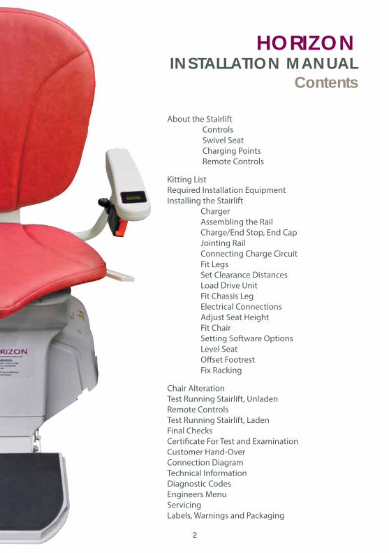
HORIZONInstallation Manual
Version: 01/5/16
2
HORIZONINSTALLATION MANUAL
Contents
About the Stairlift
Controls
Swivel Seat
Charging Points
Remote Controls
Kitting List
Required Installation Equipment
Installing the Stairlift
Charger
Assembling the Rail
Charge/End Stop, End Cap
Jointing Rail
Connecting Charge Circuit
Fit Legs
Set Clearance Distances
Load Drive Unit
Fit Chassis Leg
Electrical Connections
Adjust Seat Height
Fit Chair
Setting Software Options
Level Seat
Offset Footrest
Fix Racking
Chair Alteration
Test Running Stairlift, Unladen
Remote Controls
Test Running Stairlift, Laden
Final Checks
Certificate For Test and Examination
Customer Hand-Over
Connection Diagram
Technical Information
Diagnostic Codes
Engineers Menu
Servicing
Labels, Warnings and Packaging
3
ABOUT THIS MANUALDescription of this manualThis manual is intended to show you how to install a Platinum Horizon Standard stairlift.
This manual contains detailed instructions about:
• Required Knowledge
• Typical Kitting List of Parts in a Platinum Horizon stairlift
• Required Installation Equipment you will need to install a stairlift
• Health and Safety Guidance
• Installing the stairlift
• Testing the stairlift
• Troubleshooting
• Technical Information and System Status Codes
• Instructing the User how to Use the Product Paperwork
• Quick Reference Guide
Required knowledgeThis manual assumes that you have the following knowledge:
• Basic Mechanical Skills - so you understand what the components of the stairlift
do and how they fit and work together
• Basic Wiring Skills - so you understand how the stairlift is connected to the mains
power supply; and what the electrical components of the stairlift do and how they
fit and work together
• Health and Safety Awareness - so you are fully aware of and responsible for the
health and safety of yourself and the people around you
4
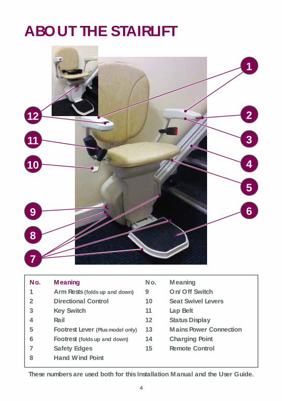
ABOUT THE STAIRLIFT
No. Meaning1 Arm Rests (folds up and down)
2 Directional Control3 Key Switch4 Rail5 Footrest Lever (Plus model only)
6 Footrest (folds up and down)
7 Safety Edges8 Hand Wind Point
No. Meaning9 On/Off Switch10 Seat Swivel Levers11 Lap Belt12 Status Display13 Mains Power Connection14 Charging Point15 Remote Control
These numbers are used both for this Installation Manual and the User Guide.
12
11
10
9
8
7
1
2
3
4
5
6
5
CONTROLS
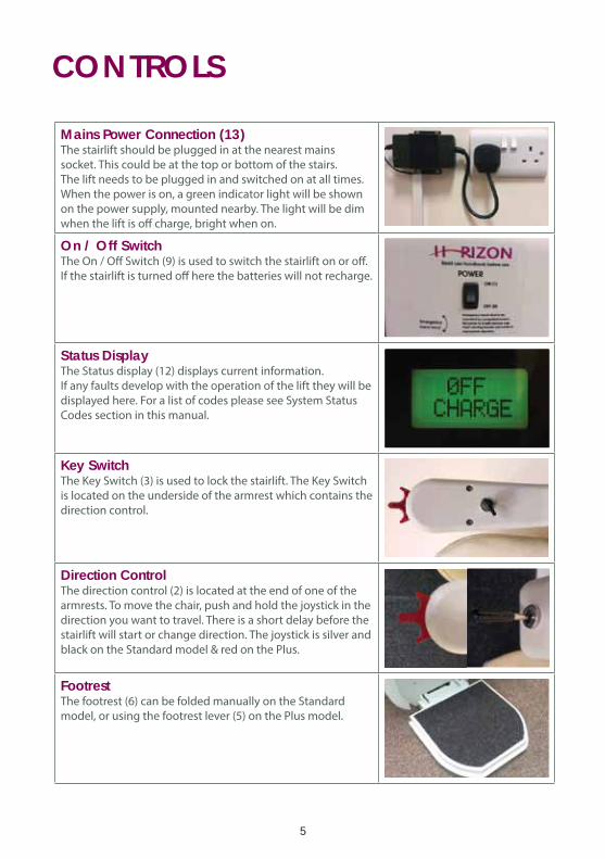
Mains Power Connection (13)The stairlift should be plugged in at the nearest mains
socket. This could be at the top or bottom of the stairs.
The lift needs to be plugged in and switched on at all times.
When the power is on, a green indicator light will be shown
on the power supply, mounted nearby. The light will be dim
when the lift is off charge, bright when on.
On / Off SwitchThe On / Off Switch (9) is used to switch the stairlift on or off.
If the stairlift is turned off here the batteries will not recharge.
Status DisplayThe Status display (12) displays current information.
If any faults develop with the operation of the lift they will be
displayed here. For a list of codes please see System Status
Codes section in this manual.
Key SwitchThe Key Switch (3) is used to lock the stairlift. The Key Switch
is located on the underside of the armrest which contains the
direction control.
Direction ControlThe direction control (2) is located at the end of one of the
armrests. To move the chair, push and hold the joystick in the
direction you want to travel. There is a short delay before the
stairlift will start or change direction. The joystick is silver and
black on the Standard model & red on the Plus.
FootrestThe footrest (6) can be folded manually on the Standard
model, or using the footrest lever (5) on the Plus model.
6
SWIVEL SEAT
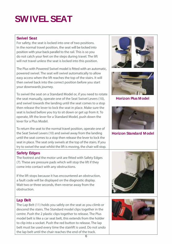
Swivel SeatFor safety, the seat is locked into one of two positions.
In the normal travel position, the seat will be locked into
position with your back parallel to the rail. This is so you
do not catch your feet on the steps during travel. The lift
will not travel unless the seat is locked into this position.
The Plus with Powered Swivel model is fitted with an automatic,
powered swivel. The seat will swivel automatically to allow
easy access when the lift reaches the top of the stairs. It will
then swivel back into the correct position before you start
your downwards journey.
To swivel the seat on a Standard Model or, if you need to rotate
the seat manually, operate one of the Seat Swivel Levers (10),
and swivel towards the landing until the seat comes to a stop
then release the lever to lock the seat in place. Make sure the
seat is locked before you try to sit down or get up from it. To
operate, lift the lever for a Standard Model, push down the
lever for a Plus Model.
To return the seat to the normal travel position, operate one of
the Seat Swivel Levers (10) and swivel away from the landing
until the seat comes to a stop then release the lever to lock the
seat in place. The seat only swivels at the top of the stairs. If you
try to swivel the seat whilst the lift is moving, the chair will stop.
Safety EdgesThe footrest and the motor unit are fitted with Safety Edges
(7). These are pressure pads which will stop the lift if they
come into contact with any obstructions.
If the lift stops because it has encountered an obstruction,
a fault code will be displayed on the diagnostic display.
Wait two or three seconds, then reverse away from the
obstruction.
Lap BeltThe Lap Belt (11) holds you safely on the seat as you climb or
descend the stairs. The Standard model clips together in the
centre. Push the 2 plastic clips together to release. The Plus
model belt is like a car seat belt, this extends from the holder
to clip into a socket. Push the red button to release. The lap
belt must be used every time the stairlift is used. Do not undo
the lap belt until the chair reaches the end of the track.
Horizon Plus Model
Horizon Standard Model
7
CHARGE POINTS & REMOTES
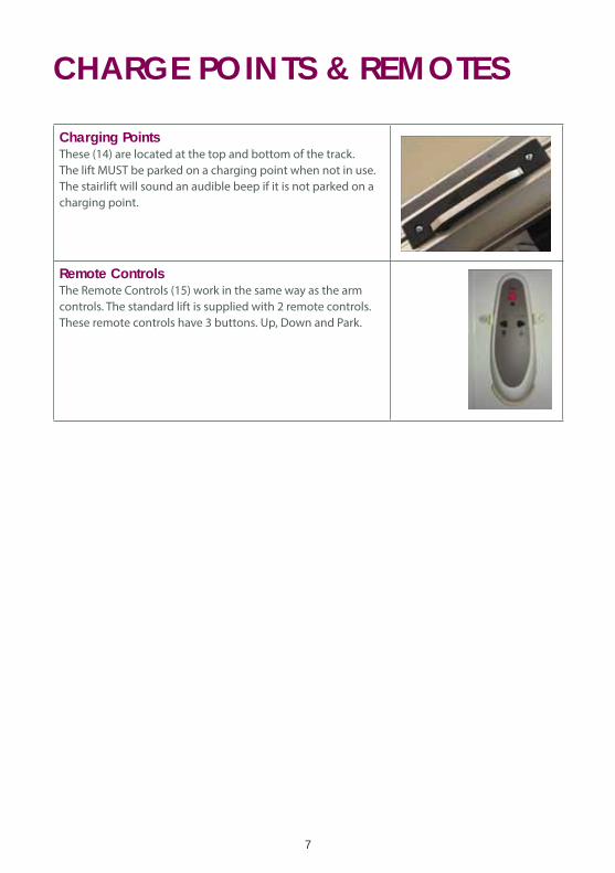
Charging PointsThese (14) are located at the top and bottom of the track.
The lift MUST be parked on a charging point when not in use.
The stairlift will sound an audible beep if it is not parked on a
charging point.
Remote ControlsThe Remote Controls (15) work in the same way as the arm
controls. The standard lift is supplied with 2 remote controls.
These remote controls have 3 buttons. Up, Down and Park.
8
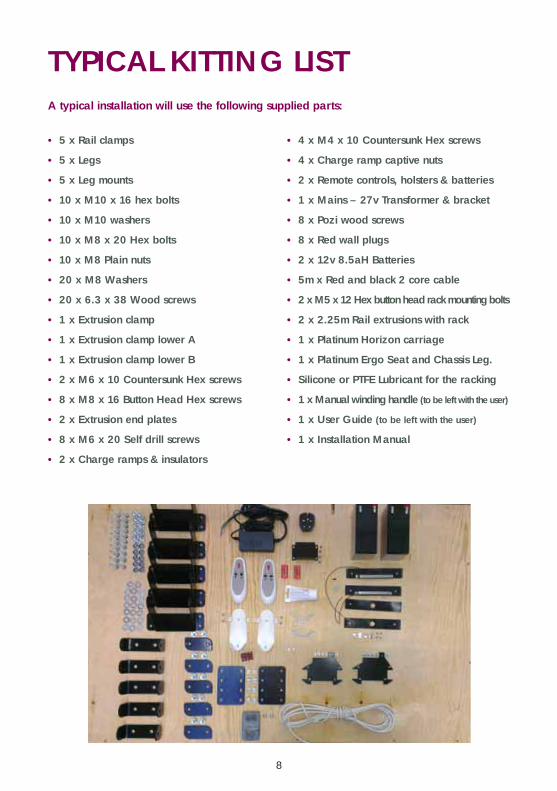
TYPICAL KITTING LIST
• 5 x Rail clamps
• 5 x Legs
• 5 x Leg mounts
• 10 x M10 x 16 hex bolts
• 10 x M10 washers
• 10 x M8 x 20 Hex bolts
• 10 x M8 Plain nuts
• 20 x M8 Washers
• 20 x 6.3 x 38 Wood screws
• 1 x Extrusion clamp
• 1 x Extrusion clamp lower A
• 1 x Extrusion clamp lower B
• 2 x M6 x 10 Countersunk Hex screws
• 8 x M8 x 16 Button Head Hex screws
• 2 x Extrusion end plates
• 8 x M6 x 20 Self drill screws
• 2 x Charge ramps & insulators
• 4 x M4 x 10 Countersunk Hex screws
• 4 x Charge ramp captive nuts
• 2 x Remote controls, holsters & batteries
• 1 x Mains – 27v Transformer & bracket
• 8 x Pozi wood screws
• 8 x Red wall plugs
• 2 x 12v 8.5aH Batteries
• 5m x Red and black 2 core cable
• 2 x M5 x 12 Hex button head rack mounting bolts
• 2 x 2.25m Rail extrusions with rack
• 1 x Platinum Horizon carriage
• 1 x Platinum Ergo Seat and Chassis Leg.
• Silicone or PTFE Lubricant for the racking
• 1 x Manual winding handle (to be left with the user)
• 1 x User Guide (to be left with the user)
• 1 x Installation Manual
A typical installation will use the following supplied parts:
9
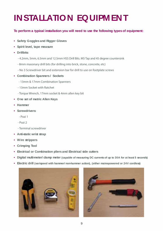
INSTALLATION EQUIPMENT
• Safety Goggles and Rigger Gloves
• Spirit level, tape measure
• Drillbits:
- 4.2mm, 5mm, 6.5mm and 12.5mm HSS Drill Bits. M5 Tap and 45 degree countersink
- 8mm masonary drill bits (for drilling into brick, stone, concrete, etc)
- No 3 Screwdriver bit and extension bar for drill to use on footplate screws
• Combination Spanners / Sockets
- 13mm & 17mm Combination Spanners
- 13mm Socket with Ratchet
- Torque Wrench, 17mm socket & 4mm allen key bit
• One set of metric Allen Keys
• Hammer
• Screwdrivers:
- Pozi 1
- Pozi 2
- Terminal screwdriver
• Anti-static wrist strap
• Wire strippers
• Crimping Tool
• Electrical or Combination pliers and Electrical side cutters
• Digital multi-meter/clamp meter (capable of measuring DC currents of up to 30A for at least 5 seconds)
• Electric drill (varispeed with hammer/non-hammer action), (either mains-powered or 24V cordless)
To perform a typical installation you will need to use the following types of equipment:
10
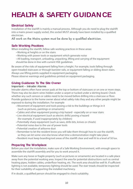
HEALTH & SAFETY GUIDANCEElectrical SafetyInstallation of the stairlift is mainly a manual process. Although you do need to plug the stairlift
into a mains power supply socket, this socket MUST already have been installed by a qualified
electrician.
Safe Working PracticesWhen installing the stairlift, follow safe working practices in these areas:
• Working at heights or on the stairs
• Working with power tools or equipment which generate noise
• All loading, transport, unloading, unpacking, lifting and carrying of the equipment
should be done in line with current HSE guidelines
Be aware of the risks of equipment falling from a height. For example, tools falling through
open-treaded staircases or through banister rails, or equipment falling or sliding down stairs.
Always use lifting points supplied in equipment packaging.
Please observe warnings and guidelines printed on equipment packaging.
Giving Guidance To The Site OwnerImportant – Intruder AlarmsIntruder alarms often have sensor pads at the top or bottom of staircases or on one or more steps.
There may also be alarm wires hidden under a carpet or tucked under a skirting board. Check
whether any such sensors or cables need to be moved before drilling into a staircase or floor.
Provide guidance to the home owner about what safety risks they and any other people might be
exposed to during the installation. For example
• Movement of equipment and tools posing a risk to the buildings or things in it
(such as pictures, paintings or ornaments)
• Cables and other equipment posing a trip hazard - especially on or near stairs
• Live electrical equipment (such as electric drills) posing a hazard
(for example, if used inappropriately by children)
• Potentially sharp equipment (such as saws, drills bits, knives or chisels)
• Potential noise due to the use of power tools
• Potential creation of airborne dust
• Remember to let the resident know you will take them through how to use the stairlift,
so they can let some-one else know what time a demonstration might take place
• Resident must keep boarding/exit areas of the stairlift clear and well lit to a level of 50 lux.
Preparing The WorkplaceBefore you start the installation, make sure of a Safe Working Environment, with enough space to
assemble the stairlift assembly and for you to work around it.
Make sure any loose or fragile property (such as pictures or ornaments) are located in a safe place
away from the potential working area. Inspect the area for potential obstructions such as central
heating pipes, hidden cables, underfloor heating, etc. The work area should be well lit. If sufficient
lighting is not available, temporary lighting should be used. The stair treads should be inspected
for their suitability of supporting the installed machinery.
If in doubt, a qualified person should be engaged to check suitability.
11
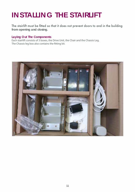
INSTALLING THE STAIRLIFT
from opening and closing.
Laying Out The ComponentsEach stairlift consists of 3 boxes, the Drive Unit, the Chair and the Chassis Leg.
The Chassis leg box also contains the fitting kit.
12
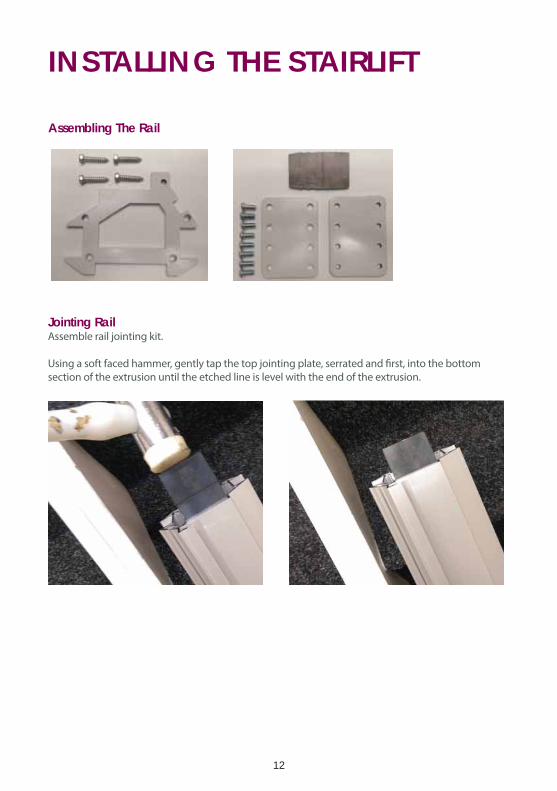
INSTALLING THE STAIRLIFT
Assembling The Rail
Jointing RailAssemble rail jointing kit.
Using a soft faced hammer, gently tap the top jointing plate, serrated and first, into the bottom
section of the extrusion until the etched line is level with the end of the extrusion.
13
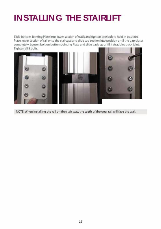
INSTALLING THE STAIRLIFT
Slide bottom Jointing Plate into lower section of track and tighten one bolt to hold in position.
Place lower section of rail onto the staircase and slide top section into position until the gap closes
completely. Loosen bolt on bottom Jointing Plate and slide back up until it straddles track joint.
Tighten all 8 bolts.
NOTE: When Installing the rail on the stair way, the teeth of the gear rail will face the wall.

14
INSTALLING THE STAIRLIFT
Set Clearance DistancesTurn rail back over and ensure that each leg sits level on
the correct step. Adjust until the rail is a minimum of 85mm
(3 1/4”), measured diagonally from the nose of the step.
This measurement is assuming that the footrest is in the central
position as supplied and can be reduced to approx. 50mm (2”) by
offsetting the footrest.
Set rail 50mm (2”) from wall, or with foot hard up against the
stinger, whichever is the greater. Ensure that the wall is vertical.
If not, base the distance from the innermost point.
Screw down rail and tighten all
leg bolts allowing for thickness
of step covering to maintain
the minimum step clearance
distance. Ensure that each foot
in attached using 4 screws
supplied.
Fit LegsAssemble legs.
Turn over rail and fit legs. On a standard length installation all 5 legs must be fitted. There must be
a leg on 1st step, legs no further than 1 step above and below the rail joint and a leg on the step be-
low landing. If fitting a powered hinge, legs must be fitted to the 1st & 2nd steps after the hinge joint.
15
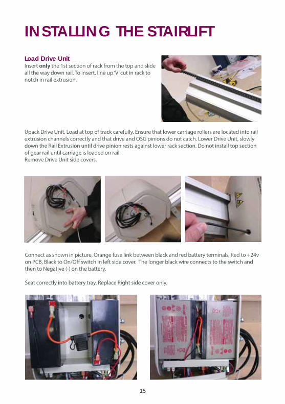
INSTALLING THE STAIRLIFTLoad Drive UnitInsert only the 1st section of rack from the top and slide
all the way down rail. To insert, line up ‘V’ cut in rack to
notch in rail extrusion.
Upack Drive Unit. Load at top of track carefully. Ensure that lower carriage rollers are located into rail
extrusion channels correctly and that drive and OSG pinions do not catch. Lower Drive Unit, slowly
down the Rail Extrusion until drive pinion rests against lower rack section. Do not install top section
of gear rail until carriage is loaded on rail.
Remove Drive Unit side covers.
Connect as shown in picture, Orange fuse link between black and red battery terminals, Red to +24v
on PCB, Black to On/Off switch in left side cover. The longer black wire connects to the switch and
then to Negative (-) on the battery.
Seat correctly into battery tray. Replace Right side cover only.
16
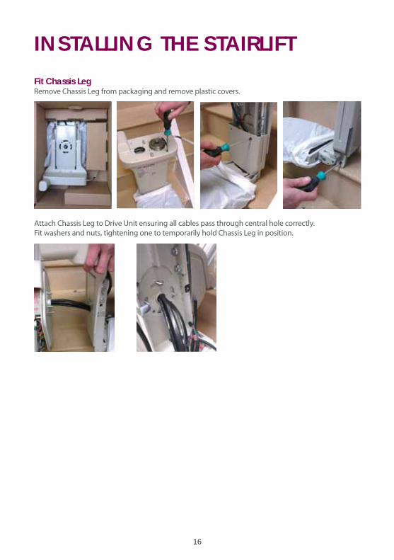
INSTALLING THE STAIRLIFTFit Chassis LegRemove Chassis Leg from packaging and remove plastic covers.
Attach Chassis Leg to Drive Unit ensuring all cables pass through central hole correctly.
Fit washers and nuts, tightening one to temporarily hold Chassis Leg in position.
17
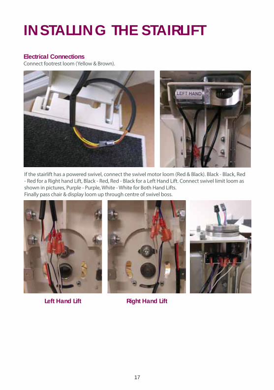
INSTALLING THE STAIRLIFTElectrical ConnectionsConnect footrest loom (Yellow & Brown).
If the stairlift has a powered swivel, connect the swivel motor loom (Red & Black). Black - Black, Red
- Red for a Right hand Lift, Black - Red, Red - Black for a Left Hand Lift. Connect swivel limit loom as
shown in pictures, Purple - Purple, White - White for Both Hand Lifts.
Finally pass chair & display loom up through centre of swivel boss.
Left Hand Lift Right Hand Lift
18
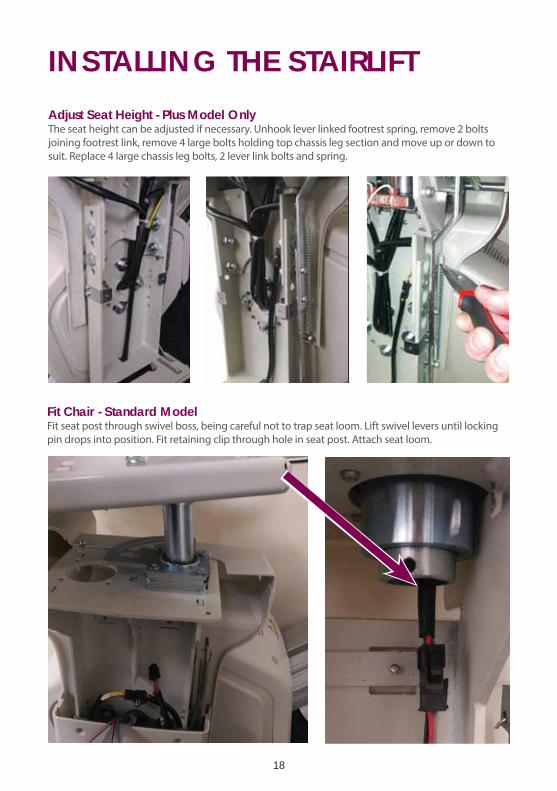
Adjust Seat Height - Plus Model OnlyThe seat height can be adjusted if necessary. Unhook lever linked footrest spring, remove 2 bolts
joining footrest link, remove 4 large bolts holding top chassis leg section and move up or down to
suit. Replace 4 large chassis leg bolts, 2 lever link bolts and spring.
Fit Chair - Standard ModelFit seat post through swivel boss, being careful not to trap seat loom. Lift swivel levers until locking
pin drops into position. Fit retaining clip through hole in seat post. Attach seat loom.
INSTALLING THE STAIRLIFT
19
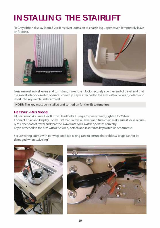
Fit Chair - Plus ModelFit Seat using 4 x 8mm Hex Button Head bolts. Using a torque wrench, tighten to 20 Nm.
Connect Chair and Display Looms. Lift manual swivel levers and turn chair, make sure it locks secure-
ly at either end of travel and that the swivel interlock switch operates correctly.
Key is attached to the arm with a tie wrap, detach and insert into keyswitch under armrest.
Secure wiring looms with tie-wrap supplied taking care to ensure that cables & plugs cannot be
damaged when swiveling”
INSTALLING THE STAIRLIFTFit Grey ribbon display loom & 2 x IR receiver looms on to chassis leg upper cover. Temporarily leave
on footrest.
Press manual swivel levers and turn chair, make sure it locks securely at either end of travel and that
the swivel interlock switch operates correctly. Key is attached to the arm with a tie wrap, detach and
insert into keyswitch under armrest.
NOTE: The key must be installed and turned on for the lift to function.
20
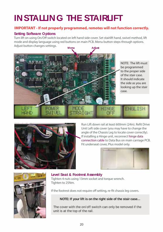
INSTALLING THE STAIRLIFTSetting Software OptionsTurn lift on using On/Off switch located on left hand side cover. Set stairlift hand, swivel method, lift
mode and display language using red buttons on main PCB. Menu button steps through options.
Adjust button changes settings.Menu Adjust
Run Lift down rail at least 600mm (24in). Refit Drive
Unit Left side cover (you may have to change the
angle of the Chassis Leg to locate cover correctly).
If installing a Hinge unit, reconnect hinge data
connection cable to Data Bus on main carriage PCB.
Fit underseat cover, Plus model only.
Level Seat & Footrest AssemblyTighten 4 nuts using 13mm socket and torque wrench.
Tighten to 25Nm.
If the footrest does not require off setting, re-fit chassis leg covers.
NOTE: The lift must
be programmed
to the proper side
of the stair case.
It should indicate
the side as you are
looking up the stair
case.
IMPORTANT - If not properly programmed, remotes will not function correctly.
NOTE: If your lift is on the right side of the stair case...
The cover with the on/off switch can only be removed if the unit is at the top of the rail.
21
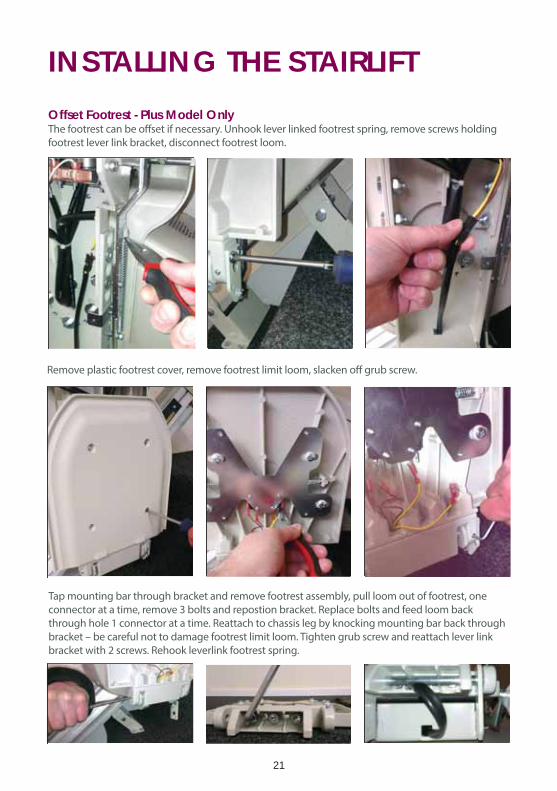
INSTALLING THE STAIRLIFTOffset Footrest - Plus Model OnlyThe footrest can be offset if necessary. Unhook lever linked footrest spring, remove screws holding
footrest lever link bracket, disconnect footrest loom.
Remove plastic footrest cover, remove footrest limit loom, slacken off grub screw.
Tap mounting bar through bracket and remove footrest assembly, pull loom out of footrest, one
connector at a time, remove 3 bolts and repostion bracket. Replace bolts and feed loom back
through hole 1 connector at a time. Reattach to chassis leg by knocking mounting bar back through
bracket – be careful not to damage footrest limit loom. Tighten grub screw and reattach lever link
bracket with 2 screws. Rehook leverlink footrest spring.
22
INSTALLING THE STAIRLIFT
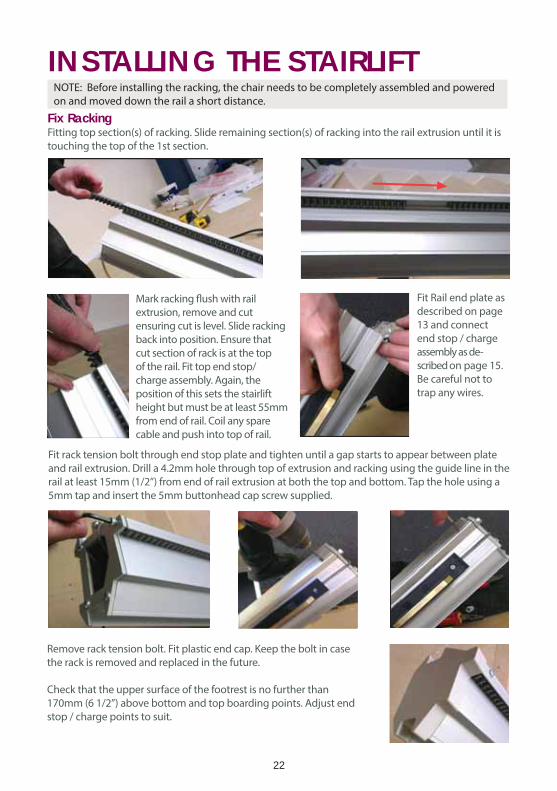
Fix RackingFitting top section(s) of racking. Slide remaining section(s) of racking into the rail extrusion until it is
touching the top of the 1st section.
Mark racking flush with rail
extrusion, remove and cut
ensuring cut is level. Slide racking
back into position. Ensure that
cut section of rack is at the top
of the rail. Fit top end stop/
charge assembly. Again, the
position of this sets the stairlift
height but must be at least 55mm
from end of rail. Coil any spare
cable and push into top of rail.
Fit Rail end plate as
described on page
13 and connect
end stop / charge
assembly as de-
scribed on page 15.
Be careful not to
trap any wires.
Fit rack tension bolt through end stop plate and tighten until a gap starts to appear between plate
and rail extrusion. Drill a 4.2mm hole through top of extrusion and racking using the guide line in the
rail at least 15mm (1/2”) from end of rail extrusion at both the top and bottom. Tap the hole using a
5mm tap and insert the 5mm buttonhead cap screw supplied.
Remove rack tension bolt. Fit plastic end cap. Keep the bolt in case
the rack is removed and replaced in the future.
Check that the upper surface of the footrest is no further than
170mm (6 1/2”) above bottom and top boarding points. Adjust end
stop / charge points to suit.
NOTE: Before installing the racking, the chair needs to be completely assembled and powered
on and moved down the rail a short distance.
23
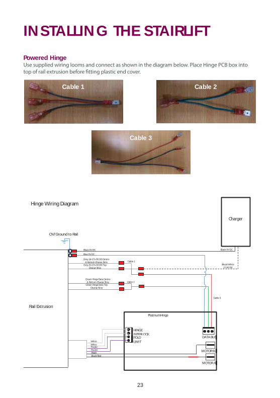
INSTALLING THE STAIRLIFTPowered HingeUse supplied wiring looms and connect as shown in the diagram below. Place Hinge PCB box into
top of rail extrusion before fitting plastic end cover.
HINGE INTERLOCK FOLD LIMIT
DATA BUS
MOTOR A
MOTOR B
PlatinumHinge
White White PurplePurpleBlack Black/Red
Charger
Black/White 27.6V DC
Black 0V DC
OV/Ground to Rail
Rail Extrusion
Black 0V DC
Blue 0V DC
Grey 24-27v DC DC Centre & Bottom Charge Strip
Grey 24-27v DC DC Top Charge Strip
Green Hinge Data Centre & Bottom Charge Strip
Green Hinge Data Top Charge Strip
Hinge Wiring Diagram
Cable 1
Cable 2
Cable 3
Cable 1
Cable 3
Cable 2
24
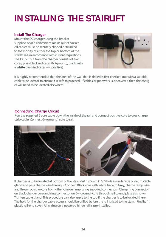
Install The ChargerMount the DC charger using the bracket
supplied near a convenient mains outlet socket.
All cables must be securely clipped or trunked
to the vicinity of either the top or bottom of the
stairlift rail, in accordance with current regulations.
The DC output from the charger consists of two
cores, plain black indicates 0v (ground), black with
a white dash indicates +v (positive).
It is highly recommended that the area of the wall that is drilled is first checked out with a suitable
cable/pipe locator to ensure it is safe to proceed. If cables or pipework is discovered then the charg-
er will need to be located elsewhere.
INSTALLING THE STAIRLIFT
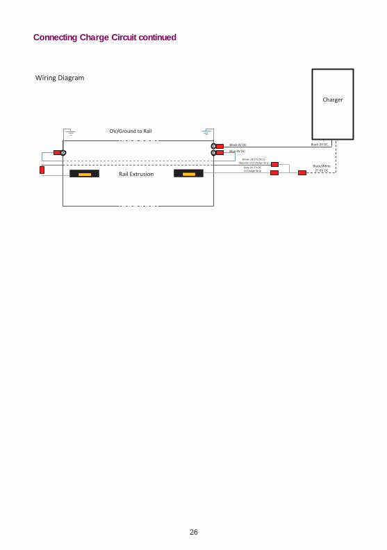
Connecting Charge CircuitRun the supplied 2 core cable down the inside of the rail and connect positive core to grey charge
strip cable. Connect 0v (ground) core to rail.
If charger is to be located at bottom of the stairs drill 12.5mm (1/2”) hole in underside of rail, fit cable
gland and pass charge wire through. Connect Black core with white trace to Grey, charge ramp wire
and Brown positive core from other charge ramp using supplied connectors. Clamp ring connector
on Black charger core and ring connector on 0v (ground) core through rail to end plate as shown.
Tighten cable gland. This procedure can also apply to the top if the charger is to be located there.
The hole for the charger cable access should be drilled before the rail is fixed to the stairs. Finally, fit
plastic rail-end cover. All wiring on a powered hinge rail is pre-installed.
25
INSTALLING THE STAIRLIFT
At this point, check the rail for correct operation - with the power OFF and using a suitable meter
measure between all of the copper charging points and the chassis of the rail and ensure these
points are not short circuit to the chassis, if they are it is quite likely that the cable from the charging
point has been broken into by the screw holding the charging point in place. Check this and any
other points where the insulation of the cabling may have broken down. Do not power the rail until
this test has been successfully carried out.
Following this, apply power to the rail and ensure that approximately 27v can be measured from
both the upper and lower charging points using the rail chassis as the 0v (ground) point. If a pow-
ered hinge is part of the installation then the charging points above the hinge may have 2 copper
strips on them, if this is the case then, using the rail as the 0v (ground) reference you need to meas-
ure approx 27v on the upper copper strip and 15v on the lower copper strip.
IMPORTANT - DO NOT PROCEED WITH THE INSTALL UNTIL THE ABOVE HAS BEEN CARRIED OUT AND
CONFIRMED AS FULLY WORKING.
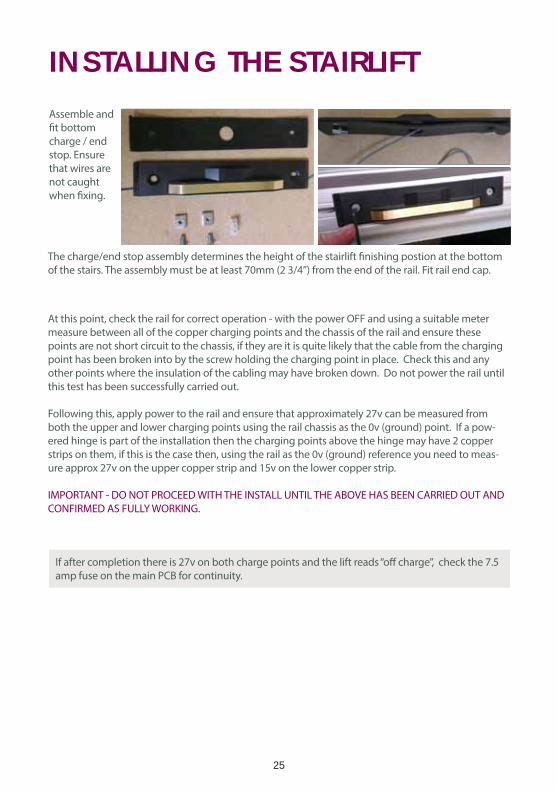
Assemble and
fit bottom
charge / end
stop. Ensure
that wires are
not caught
when fixing.
The charge/end stop assembly determines the height of the stairlift finishing postion at the bottom
of the stairs. The assembly must be at least 70mm (2 3/4”) from the end of the rail. Fit rail end cap.
If after completion there is 27v on both charge points and the lift reads “off charge”, check the 7.5
amp fuse on the main PCB for continuity.
26
Connecting Charge Circuit continued
27
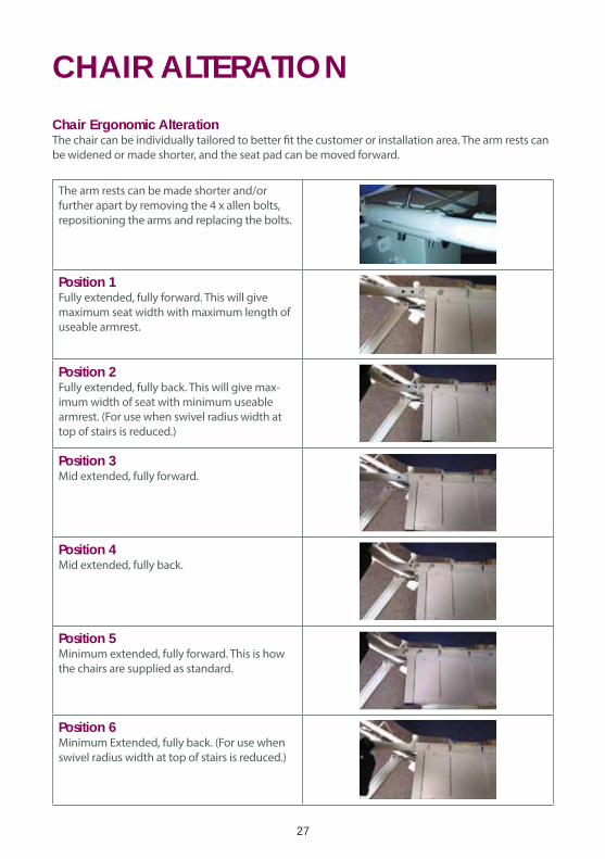
CHAIR ALTERATIONChair Ergonomic AlterationThe chair can be individually tailored to better fit the customer or installation area. The arm rests can
be widened or made shorter, and the seat pad can be moved forward.
The arm rests can be made shorter and/or
further apart by removing the 4 x allen bolts,
repositioning the arms and replacing the bolts.
Position 1Fully extended, fully forward. This will give
maximum seat width with maximum length of
useable armrest.
Position 2Fully extended, fully back. This will give max-
imum width of seat with minimum useable
armrest. (For use when swivel radius width at
top of stairs is reduced.)
Position 3Mid extended, fully forward.
Position 4Mid extended, fully back.
Position 5Minimum extended, fully forward. This is how
the chairs are supplied as standard.
Position 6Minimum Extended, fully back. (For use when
swivel radius width at top of stairs is reduced.)
28
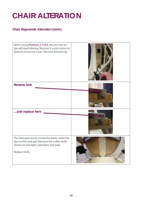
CHAIR ALTERATIONChair Ergonomic Alteration (cont.)
When using Positions 2, 4 & 6, the arm rest an-
gle will need altering. Remove 4 x pozi screws in
bottom of armrest cover. Remove armrest top.
Remove bolt
...and replace here
The Seat pad can be moved forwards. Undo the
zips on the seat pad. Remove the 4 allen bolts
shown on the right, reposition seat pad.
Replace bolts.
29
TEST RUNNING THE STAIRLIFT (1)Test Running Stairlift - Unladen
Important: If there are any issues with the stairlift, the system may display System Status Codes.Refer to the System Status Codes section for more details of what these codes mean.
To test run the stairlift (unladen): Make sure the area covered by the movement of the stairlift is free of obstructions.
Fold down the footrest and swivel the seat into correct travel position. Leave the armrests in the
upright position. Do not allow any weight to rest on the carriage as yet.
Run the unladen stairlift to the very bottom of the track. While the stairlift is travelling check:
1. Footrest to riser.
2. Armrest and seat back, especially on staircases with low bulkheads.
3. Seat back to wall/newel
4. Arm rest to wall when swivelled.
At the bottom check that the stairlift is charging correctly and the footrest is at the correct height to
allow the user to easily access the stairlift.
Run the stairlift to the top of the track while checking all above points.
At the top check that the stairlift is charging correctly and the footrest is at the correct height to
allow the user to easily access the stairlift. Also check the swivel radius to ensure that the downside
armrest does not come into contact with the opposite side of the staircase.
30
Installing the Remote ControlsThere are 2 types of remote control, Infra-Red (IR) & Radio Frequency (RF). Each system comes with
2 remote controls as standard. More can be added if required. IR control is supplied as standard, RF
control is an available option if local IR interference is causing an issue.
The controls have 3 buttons, Up, Down and a red Park button. The park button is only used in con-
junction with the optional intermediate charge point.
To install the remote controls: Infra-RedThe infra-red receivers are mounted in the arm of the chair.
Fit the batteries into the remote controls, then use each of them to call and send the stairlift to and
from the other end of the track and then back again.
Locate suitable locations for the control holsters to be mounted, confirm these postions are suitable
for the customer, and screw into position.
The controls are sent pre-programmed to the PCB. However, if there are several stairlifts installed
in close proximity or there are other infra-red/radio sources in the area creating interference, the
Infra-Red signals for each of the stairlifts can be changed so that they do not interfere with each
other.
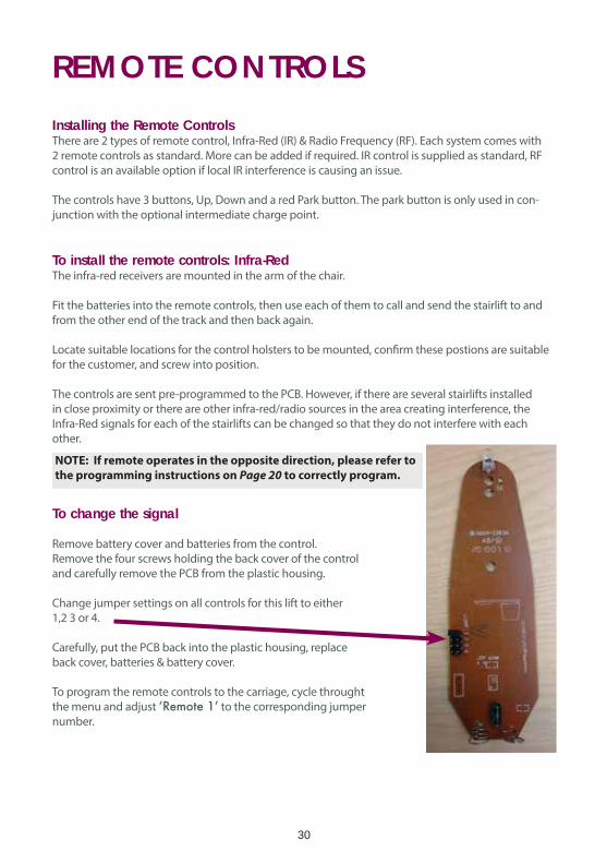
To change the signal
Remove battery cover and batteries from the control.
Remove the four screws holding the back cover of the control
and carefully remove the PCB from the plastic housing.
Change jumper settings on all controls for this lift to either
1,2 3 or 4.
Carefully, put the PCB back into the plastic housing, replace
back cover, batteries & battery cover.
To program the remote controls to the carriage, cycle throught
the menu and adjust to the corresponding jumper
number.
REMOTE CONTROLS
NOTE: If remote operates in the opposite direction, please refer to
the programming instructions on Page 20 to correctly program.
31
TEST RUNNING THE STAIRLIFT (2)Test Running Stairlift - Fully Laden
Test running the stairlift fully laden ensures the lift is working correctly, and that it clears any obstacles.
It also begins the bedding in process. Please ensure that the rack is lubricated with a suitable silicone
or synthetic PTFE based grease at this point. We recommend that you lubricate three teeth every
300mm on the rack.
To test run the stairlift (fully laden): Move the stairlift to the bottom of the track, fold down the armrests and footrest, Load the chair to
capacity. Using one of the remote controls, send the stairlift to the top of the rail. Keep direction con-
trol activated to ensure chair automatically swivels to safe entry/exit position. Press remote control in
opposite direction to ensure chair swivels back to correct travel position.
To test manual swivel, lift swivel levers, and ensure chair will swivel into correct entry/exit position.
Press direction control in downwards direction to ensure swivel interlock switch is working, and
stairlift will not decend in this position. Lift swivel levers and ensure chair swivels back to correct
travel position.
Use remote control to send stairlift down the stairs, stop part way along the rail and then reverse
direction to bring stairlift back to the top, ensuring the stairlift stops correctly.
Use the remote control to travel down the stairs. Ensure the stairlift stops correctly.
Make sure the stairlift comes to a stop quickly, if you do any of the following actions:
Let go of the direction control.
Encounter an obstruction with the footrest.
Encounter an obstruction with the safety pads on the carriage.
Swivel the seat.
Run the stairlift from one end of the track to the other; then return it to its original position. For both
trips make sure it runs freely and smoothly, and proceeds clear of stair treads and any other fixed
obstructions. At one end of the track, stop the stairlift at one end of the track, undo the seatbelt and
make sure the plug part of the lock retracts into its housing.
Lift up the seat, footrest and arm rests and make sure they all stay upright.
Run the stairlift to the middle of the track, then stop it.
Use the hand-winding procedure to make sure the chair can be hand-wound both up and down the
track.
32
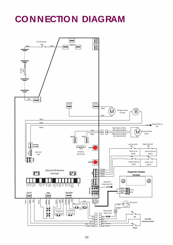
CONNECTION DIAGRAM
LEFT
CA
LL
FEED
RIG
HT
CALL
LE
FT
EDG
E
CALL
U
P
FEED
RIG
HT
EDG
E
CALL
D
OW
N
FEED
RIG
HT
STO
P
FEED
LEFT
ST
OP
FEED
SAFE
TY
CIRC
UIT
FE
ED
10 Amp Fuse
GROUND
MOTOR B MOTOR A
SEAT B SEAT A
MENU
ADJUST
24V BATT
BATTERY CHARGER
BRAKE
DATA BU
S
SEAT EN
COD
ER
CALL UP FEED CALL DOWN
24V OU
T 2
24V OU
T
Diagnostic Display Module
DATA BUS
Manual Seat Swivel Limit
Arm-Rest Direction Control
Grey
Grey
Red - Up
Black - Common
Green – Down
Black
White
Up
Down
Brow
n
Gre
en
Blac
k
Red
Blue
Yello
w
Yello
w
Brow
n
Key Switch
Track End Limit Down
Ora
nge
Track End Limit Up
Gre
y
Grey
Safety Gear limit
Over-Run Final limit
Grey
Green – Down
Black - Common
Red - Up
Grey
Grey
Blue
Ora
nge
20 A
mp
Fuse
O
rang
e
On/Off Switch
M
Charge Pick-up Pin
Powered Swivel Motor
Carriage Motor & Brake B
M
Swivel Interlock Switch
Swivel Limit Switch
Black Black
Red
Red
Black
Red
Black
Black
Black
White
White White
Purple Purple
Black
Red Green
Blac
k
Red
Gre
en
Ora
nge
Swivel Interlock Switch
Swivel Limit Switch
Left Hand Lift Right Hand Lift
Optional RF Receiver Interface
Optional P. Hinge Data Pick-
10 Amp
Fuse
Data Line Fuse
Powered Swivel Fuse
Right Hand Lift Red, Left Hand Lift Black
Right Hand Lift Black, Left Hand Lift Red
33
TECHNICAL INFORMATIONWeight LimitsThe stairlift has been designed to carry one person only, in a seated position. The stairlift has a
maximum weight limit of 264lbs (140kg).
Operating Periods/Excessive UseThe stairlift has been designed to run for four minutes with a break of at least six minutes afterwards.
If you use the stairlift too often without taking a break, the motor will not cool down between
journeys and may become damaged.
Replacement BatteriesWe recommend that the batteries in each remote control are renewed at least every six months.
This is the responsibilty of the user.
MaintenanceTo maintain safe and reliable operation, the standard stairlift needs a annual safety inspection
and service.
UpholsteryCarelessness with matches, cigarettes and so on can cause a fire.
The upholstery material used on your stairlift has been tested for compliance with BS5852.
Hand Winding the StairliftIf necessary, for example to release the safety gear after the OSG has activated or to return the
carriage from an over-run position, the stairlift can be manually hand-wound using the supplied
winding handle. If the OSG has been activated, the carriage should only be hand-wound in the
upwards direction. Hand winding should only be attempted by, or under the supervision of a
competent stairlift engineer.
To hand-wind the stairlift:
•Fully insert the winding handle into the Emergency Hand Wind Mechanism Socket (8)
•Keeping the handle fully inserted, carefully rotate it as needed
•If you rotate the handle clockwise, this will move the chair to the right
•If you rotate the handle anti-clockwise, this will move the chair to the left
•Never use the stairlift when the winding handle is in the socket
•Never hand-wind the lift with a power drill
Important:
may void the warranty and may cause damage. Your stairlift should be inspected and maintained by a Platinum approved service engineer.
34
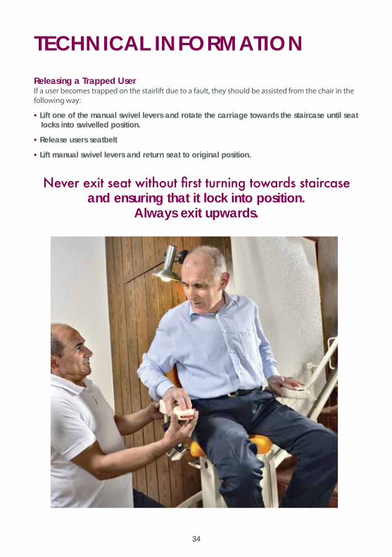
TECHNICAL INFORMATIONReleasing a Trapped UserIf a user becomes trapped on the stairlift due to a fault, they should be assisted from the chair in the
following way:
•Lift one of the manual swivel levers and rotate the carriage towards the staircase until seat locks into swivelled position.
•Release users seatbelt
•Lift manual swivel levers and return seat to original position.
and ensuring that it lock into position.
Always exit upwards.
35
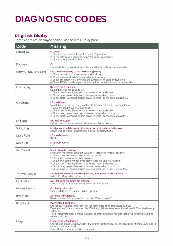
DIAGNOSTIC CODESDiagnostic DisplayThese codes are displayed on the Diagnostics Display panel.
Code MeaningNo Display No power
1. Check the battery isolator switch is in the ‘I’ position.2. Check batteries are correctly connected and in good order.3. Check 10 Amp data line fuse.
Platinum OKThe stairlift is on charge and everything is OK, lift should operate normally.
Safety Circuit / Final Limit Final Limit Fault/Safety Circuit short to 0v (ground)1. Check key switch is on connected and working.2. Check seat swivel switch is connected and working.3. Check if the stairlift has over-run and switch is connected and working.4. Check if OSG and safety gear has actioned and switch is connected and working.
Low Battery Batteries Need ChargingStairlift batteries are down to 21V.1. Check transformer is plugged in to mains socket and turned on.2. Check charging point voltage is present unloaded and loaded.3. Check charge voltage is present on white charge connector on main PCB.
Off Charge Lift is off ChargeStairlift batteries are not charging (the stairlift may still work). To charge them:1. Move the stairlift to a charging point.2. Check transformer is plugged in to mains socket and turned on.3. Check charging point voltage is present unloaded and loaded.4. Check charge voltage is present on white charge connector on main PCB.
End Stop End Stop ActivatedEnsure that both track and staircase are clear of obstructions.
Safety Edge Lift stopped by safety edge in direction of travel (footplate or side cover)Ensure that both track and staircase are clear of obstructions.
Move Right Lift travel directionRight.
Move Left Lift travel directionLeft.
Seat Swivel Seat in Swivelled positionLift cannot move until powered swivel seat is returned to travel position.1. Check powered swivel option is selected in menu.2. Check lift is set as correct hand in menu.3. Check lift is at top of track and bottom skate end stop is activated. 4. Check transformer is plugged in to mains socket and turned on.5. Check charging point voltage is present unloaded and loaded.6. Check charge voltage is present on white charge connector on main PCB.
Thermal Cut Out Motor and motor drive are running too hot, overloaded lift or excessive use.Switch lift off and allow motor to cool.
Call Conflict More than one conflicting call received.Direction toggle or wall control direction button stuck on.
Release Joystick Conflicting call received.User needs to release joystick and re-input call.
Brake Fault Motor brake inoperable.Reset lift. Check brake connection on main PCB and reset lift.
Relay Fault Power relay did not closeCheck battery charge level. Reset lift. Tap Relay. If problem persists, renew PCB.There are also 3 thermal fuses on the PCB. If any of these fuses are activated, a red LED located nearby will light.This generally indicates a wiring fault on one of the circuits connected to the PCB in the surrounding area to that LED.
Hinge Hinge arm is not fully downCheck hinge arm is fully down. Run lift upwards to intermediate or top charge point and allow hinge to lower on downwards call. Check Hinge interlock circuit for operation.
36
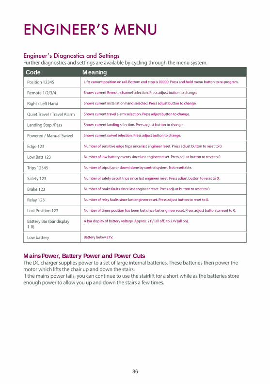
Further diagnostics and settings are available by cycling through the menu system.
Code MeaningPosition 12345 Lifts current position on rail. Bottom end stop is 00000. Press and hold menu button to re-program.
Remote 1/2/3/4 Shows current Remote channel selection. Press adjust button to change.
Right / Left Hand Shows current installation hand selected. Press adjust button to change.
Quiet Travel / Travel Alarm Shows current travel alarm selection. Press adjust button to change.
Landing Stop /Pass Shows current landing selection. Press adjust button to change.
Powered / Manual Swivel Shows current swivel selection. Press adjust button to change.
Edge 123 Number of sensitive edge trips since last engineer reset. Press adjust button to reset to 0.
Low Batt 123 Number of low battery events since last engineer reset. Press adjust button to reset to 0.
Trips 12345 Number of trips (up or down) done by control system. Not resettable.
Safety 123 Number of safety circuit trips since last engineer reset. Press adjust button to reset to 0.
Brake 123 Number of brake faults since last engineer reset. Press adjust button to reset to 0.
Relay 123 Number of relay faults since last engineer reset. Press adjust button to reset to 0.
Lost Position 123 Number of times position has been lost since last engineer reset. Press adjust button to reset to 0.
Battery Bar (bar display
1-8)
A bar display of battery voltage. Approx. 21V (all off) to 27V (all on).
Low battery Battery below 21V.
Mains Power, Battery Power and Power CutsThe DC charger supplies power to a set of large internal batteries. These batteries then power the
motor which lifts the chair up and down the stairs.
If the mains power fails, you can continue to use the stairlift for a short while as the batteries store
enough power to allow you up and down the stairs a few times.

37
SERVICINGServicingThe Standard Horizon stairlift requires a service every 12 months.
If working on the drive unit while still mounted on the rail extrusion, it is advisable to move
current HSE manual handling guidelines.
Service Carriage • Remove carriage from rail. Turn off. Remove plastic side covers. • Check rollers for wear/damage. If replacing, lubricate roller shafts lightly. • Check pinion for wear/damage. • Check all rollers rotate freely. If necessary lubricate roller shafts lightly. • Check all wires and connectors for damage & and operation of all switches. • Check operation of OSG and safety gear. • • Remove any debris including excessive, built up grease and clean all surfaces. • Check all wiring and connectors to PCB. • Check all wiring and connectors to batteries. • Check battery condition. Replace if necessary. • Check hand-wind mechanism operates correctly. • Check wiring, connectors and switches on side cover safety edges. • Ensure footrest operates correctly. • Ensure footplate safety edges operate correctly. • • • Ensure Diagnostic Display shows correct codes. • Check all wiring and connectors. • Ensure the 4 x M8 Hex bolts are tightened to a torque of 25 Nm. • Ensure manual swivel mechanism is free of debris and operates correctly. • Ensure swivel interlock switch operates correctly. • Remove plastic covers around powered swivel, check all wiring and connectors, ensure the area is free of debris. Check operation and replace plastic covers. • Check arm rests operate correctly. • Check seat belt operates correctly. • Check all controls operate correctly. • Remove plastic seat base cover. • Check wiring, connectors and switches on manual swivel limit. • Ensure the 4 x M5 Hex bolts are tightened to a torque of 20 Nm
Service Rail • Clean excessive grease off racking and inspect for damage/wear. If necessary re-apply lubrication. We recommend that you lubricate three teeth every 300mm on the rack. • • Clean rail and inspect for damage. • • • • Check charge circuit is operating correctly. • Check carriage stops in the correct position at the top and bottom.

38
SERVICINGIf Hinge Rail • Check operation of limit switches. • Check operation of plastic guard covers. • Check operation of Hinge rail • Clean excessive grease of mechanism and check for damage. If necessary re-apply lubrication.

NOTES

Customer Service: 1 (800) 922-3659 - 8AM-5PM EST3901 Commerce Park Drive • Raleigh, NC 27610
www.ameriglide.com
AmeriGlideAccessibility
Solutions