horn antenna
DESCRIPTION
topic in awpTRANSCRIPT
Horn antennas, types,
Horn antennas are generally used at microwave frequencies with moderate power gain.Horn antennas are also used as a standard for calibration and gain measurement of other antennas. They are also used as primary radiators for reflector antennas.A Horn Antenna is a flared waveguide.
Rectangular waveguide circular waveguide
When the flaring is done in only one particular direction of rectangular

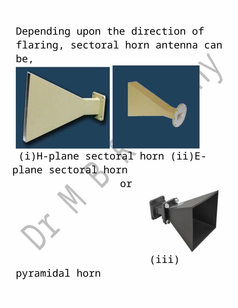
wave guide , the result will be sectoral horn antenna. Depending upon the direction of flaring, sectoral horn antenna can be,
(i)H-plane sectoral horn (ii)E-plane sectoral horn
or
(iii) pyramidal horn
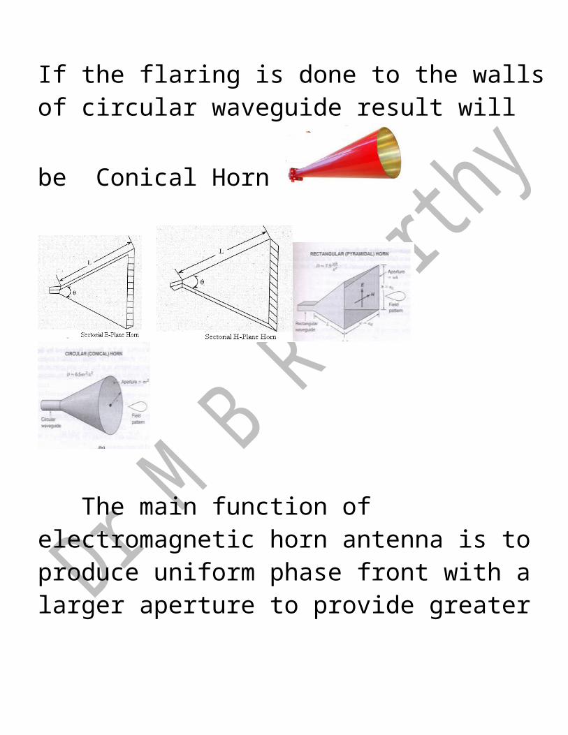
If the flaring is done to the walls of circular waveguide result will be Conical
Horn
The main function of electromagnetic horn antenna is to produce uniform phase front with a larger aperture to provide greater directivity. and better impedance matching .
Principle of equality of path length-Fermat’s principle:Fermat’s principle: or principle of equality of path length is applicable in horn design.
Light or radiation travelling between two points takes that path which takes least time. Light waves travel from point A to B by all possible routes ABj . These various paths vary by amounts greatly in excess of λ. Waves arriving at B have large range of phases and tend to interfere destructively. But if there is a short route ABo a considerable number of neighboring routes close to ABo will have optical paths differing from ABo by second order amounts only and will therefore interfere constructively. Thus instead of having constant phase across the horn mouth it is enough if phase deviation is less than a specified amount equal to path length difference between rays travelling along the axis and along the side of horn.

Cos(θ/2)= L/(L+δ); Sin(θ/2) = a/2(L+δ); Tan (θ/2)=a/2L Θ is flare angle in degrees: θE - E plane; θH -H plane. a is aperture: aE - E plane; aH - H planeL is horn length,
is path difference.For <<<LFrom L2+a2/4=(L+)2 we can approximateL=a2/8θ = 2tan-1(a/2L) =2cos-1(L/ L +δ) These are the design equations of horn.In E plane horn is held 0.25λ or less and in H plane horn can be up to 0.4λ.If the value of flare angle is very large, t

he wave front on the mouth of the horn antenna will be curved rather than plane.Optimum Horn design:To obtain as uniform an aperture distribution as possible a very long horn with small flare angle is required. For practical convenience horn should be as short as possible. Optimum horn is, in between these two extremes, design to provide minimum beam width without excessive side lobe level.For given length L; as aperture a and flare angle θ are increased D increases and BW decreases.If they become very large may become equivalent to 180 electrical degrees and field at aperture edge will be in phase opposition to field along axis. Now Directivity decreases and side lobe increases.

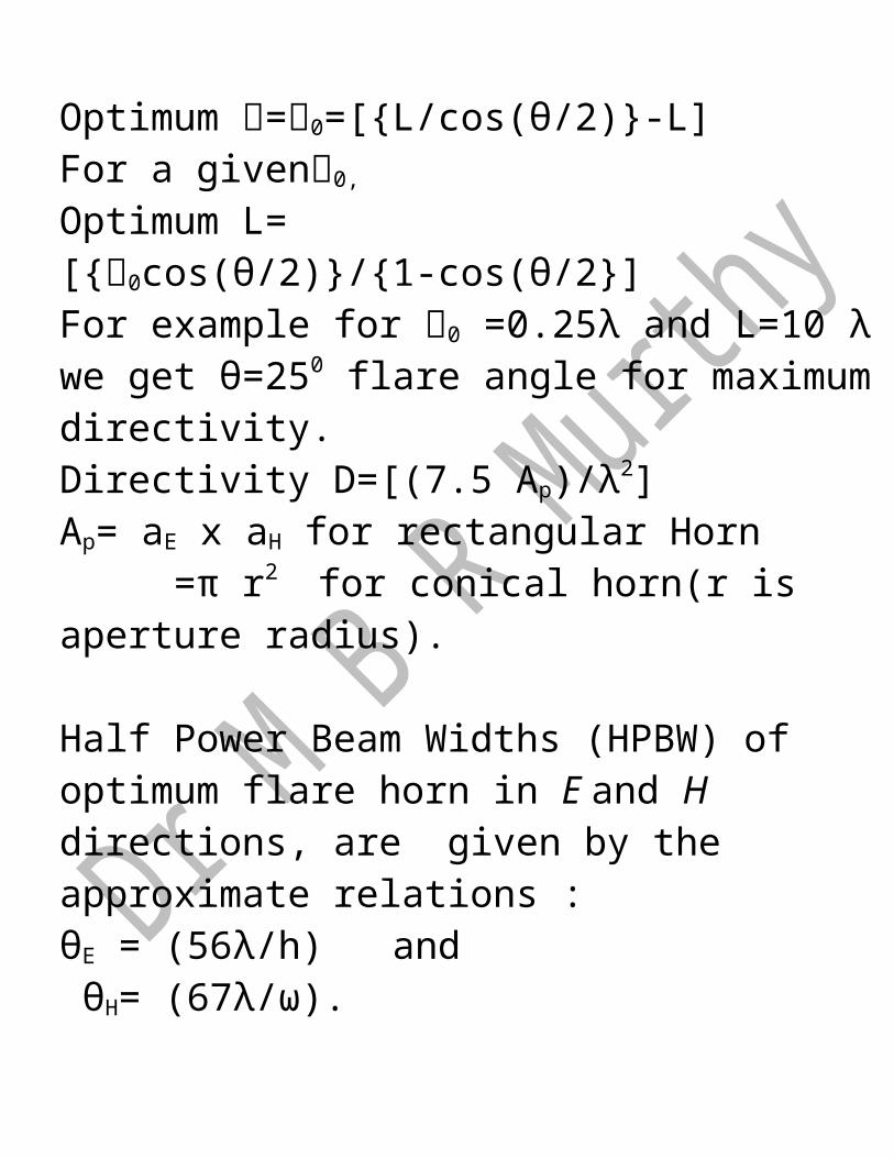
For all but very large flare angles [L/(L+) ]≈ 1. Maximum directivity occurs at largest flare angles for which does not exceed a certain value 0.( usually 0.1 to 0.4λ). The optimum horn dimensions are For a given L, Optimum =0=[{L/cos(θ/2)}-L]For a given0, Optimum L= [{0cos(θ/2)}/{1-cos(θ/2}]For example for 0 =0.25λ and L=10 λ we get θ=250 flare angle for maximum directivity.Directivity D=[(7.5 Ap)/λ2]Ap= aE x aH for rectangular Horn =π r2 for conical horn(r is aperture radius).
Half Power Beam Widths (HPBW) of optimum flare horn in E and H directions, are given by the approximate relations :

θE = (56λ/h) and θH= (67λ/ω). The pyramidal horn is most widely used It is simple to construct, versatile, has large gain and easy to excite. Used as feed element for radio astronomy.Widely used as standard to make gain measurements of other antennas.Design of optimum pyramidal horn:Specify gain G, operating wavelength λ, wave guide dimensions a,b.Use εap=0.51. Solving A4-aA3+[(3bGλ2A)/(8πεap)]= [(3G2λ4)/(32 π2+ εap
2)] - find value of A. From the relations A=√(3λR1) find R1
(R1/RH)=A/(A-a) find RH
𝓁H2=R1
2+(A/2)2 find 𝓁H
G=0.51(4π/λ2)AB , Find B B=√(2λR2) find R2
(R2/RE)= B/(B-b) find RE
𝓁E2=R2
2+(B/2)2 find 𝓁E However another approach isTo find value of A Instead of solving A4-aA3+[(3bGλ2A)/(8πεap)]= [(3G2λ4)/(32 π2+ εap
2)] a simple procedure followed is use first an approximate value for A, given by A=0.45λ , find other parameters. check RE=RH is satisfied.If not change value of A and repeat till RE = R H
Illustrative ExampleDesign an optimum pyramidal horn to operate at 9.5GHz and to provide gain of 20dB.Dimensions of WR90 waveguide a=2.286cms , b=1.016 cmsIn this problem G=20 dB=10(20/10)=102=100A=0.45λ =, 0.45x3.158x√100=14.21A B R1 R2 RE RH RE-RH
14.21 10.94 21.31 18.96 15.91 19.31 -3.4reduceA
14.0 11.10 20.69 19.53 16.34 18.78 -2.44 Diff ↓
reduceA13.8 11.26 20.11 20.1 16.77 18.28 -1.51 Diff ↓
reduceA13.6 11.43 19.53 20.69 17.21 17.78 -0.56 Diff ↓
reduceA13.4 11.6 18.96 21.31 17.68 17.28 0.4 Diff ↑
Increase A
13.5 11.51 19.24 21 17.44 17.53 -0.08 Diff ↓reduceA
13.49 11.52 19.21 21.03 17.47 17.5 -0.04 Diff ↓reduceA
13.48 11.53 19.19 21.06 17.49 17.48 0.01 Diff ↑Increase A
13.485 𝓁E =21.83 cms ; RE= 20.34 cms