horseless carriage replica …horselesscarriagereplicas.com/files/volume2issue2.pdfhorseless...
TRANSCRIPT

1
Volume 2 Issue 2 Published by Lee Thevenet March/April 2010
HORSELESS CARRIAGE REPLICA NEWSLETTERHORSELESS CARRIAGE REPLICA NEWSLETTERHORSELESS CARRIAGE REPLICA NEWSLETTERHORSELESS CARRIAGE REPLICA NEWSLETTER
A PA PA PA Publication dedicated to the reporting of news, events, articles, photos, ublication dedicated to the reporting of news, events, articles, photos, ublication dedicated to the reporting of news, events, articles, photos, ublication dedicated to the reporting of news, events, articles, photos,
items for sale, etc, having to do with replica horseless carriaitems for sale, etc, having to do with replica horseless carriaitems for sale, etc, having to do with replica horseless carriaitems for sale, etc, having to do with replica horseless carriages. ges. ges. ges. Newsletter published six times a year and special issues when needed.Newsletter published six times a year and special issues when needed.Newsletter published six times a year and special issues when needed.Newsletter published six times a year and special issues when needed.
From the EditorFrom the EditorFrom the EditorFrom the Editor With winter winds dying out and those just right cool days of spring start rolling around, we can leave the shop doors & windows open and do our yearly shop spring cleanup for safety. Right away we start thinking of finishing that winter project and start looking for new ones to begin & here is something to think about… I’m sure many of you were captivated by the accomplishments of Stu Martyn in the last issue of the HCR News. Well, as promised, we will host another article by Stu that was featured in Australian Model Engineering Magazine. With the permission of the magazines respected Editor Dave Proctor, the articles will be available as separate supplementary PDF files to the HCR News & named accordingly as they appeared in the Australian Model Engineering Magazine. This installment is Stu’s article on his Stanley, as it appeared in the Sept/Oct 2006 Issue. The AME magazine uses a smaller font in their publishing, so if it is too hard to read, just bump up the magnification on your viewer. Also for the first time; in this issue, we have included the first technical article by Mr. Everett Moore that appeared in the former E&W Newsletter, Issue 4. Mr. Moore has re-edited it with a few changes to make the article clearer to the builder. This article starts on Page 7. Enjoy! Lee
In This Issue Page From the Editor………………………....1 Tool Time…………………………………2 Toon & Crossword……………………..3 IMPORTANT to all readers…………….4 WORKSMAN WHEEL UPDATE………5-6 HCR Hobby Recognized……………...7 E&W Technical Bulletin………………8-11 Building My First Car (Part 3)………12-14 Displaying Your HCR Carriage…….14-15 A Builders Candy Store……………….16

2
Tool TimeTool TimeTool TimeTool Time ByByByBy
Lee ThevenetLee ThevenetLee ThevenetLee Thevenet
My experience with the various types of tie-downs goes back a few years to my duties in the military, when we used them for securing any gear we did not want moving around. These useful tools (yes tools) can be used in many ways & treated like your most expensive tool, rolled up, tied ( I like to tie mine to keep them from tangling up ) & put away where they will not be exposed to moisture, their worst enemy besides cuts & as your other tools, will become just as important and last a very long time. Most tie-down straps are made of a polyester weave & differ in length, width & also various weight holding capacities. Used in the shop, they serve well as clamps, storage aids & even an extra hand when needed to hold a work piece at that just right angle. In transportation, they can secure a load, keeping it from shifting or turning over when cornering or braking. Most folks use them to further secure their boats to their trailers or a classic vehicle to a trailer. I personally use them now to keep my HCR from moving inside my closed in trailer when I’m transporting it to shows or parade events. They come with variety of ends as shown in the pictures above for attaching to different types of hold down points. Check out the possibilities of use & the types available, next time you go looking for that special tool….:)

3
Toon Toon Toon Toon by Leeby Leeby Leeby Lee
I’m not sure Bubba, but I think you might have built her a bit heavy…
Crossword Crossword Crossword Crossword by Leeby Leeby Leeby Lee
Across
1..A recliner is for….
18…not willing to work is….
8…opposite of out
Down
10…A chair to relax in…
4…__ __ __ winds of war…
7…obtaining …
Make a sentence with the words Answer on page 11

4
IMPORTANT!
PLEASE READ!
Have you enjoyed the HCR Newsletters so far?
To keep bringing all of you this Newsletter
We need your imput!
We need member submitted news, stories, pictures, Items “For Sale and Wanted Listings”.
Let us know what you like or don’t like about the Newsletter. Help us make it
better for you & more informative for all…
You may send information by regular mail or E-Mail. Photographs sent by regular mail, will be returned after scanning, if self addressed / stamped envelope is included. If a digital camera is used, just E-Mail everything as a digital file…
Please document your pictures, so we know what we are looking at…
Mail to: Lee Thevenet
1657 Grand Anse Hwy Breaux Bridge, La. 70517
Or E-Mail to:

5
EXTRA! EXTRA! EXTRA!
THE WORKSMAN WHEEL - ORDERING THE CORRECT ONE By
Bob Kapela
In the previous issue of HCR News, we announced the information that you can now order the 26” Worksman wheels complete with the Kilian bearings pre-installed. These can be ordered with or without the Kevlar tires and puncture resistant tubes. This is great news for prospective builders of “Everett” or “Jimmy Woods” style replicars, and “non full-size” HCR’s. Some prospective builders had been turned off about ordering Kilian bearings separately from a bearing company because of minimum ordering requirements. Also there has been some confusion about the proper part number of the required wheel. The phone number for Worksman for sales is 1-888-394-3353. Credit cards are accepted. Be sure to mention our group of builders. You will get an order person when you call. If there are questions about the proper wheel, the “go-to” guy is Al Venditti, however, we don’t want to bother him unless it is really necessary. Way back in issue #22 of “Engine & Wheels”, when I first became acquainted with Everett, I introduced the Worksman wheels and the Kilian bearings to the group. At the time, I explained that the Worksman wheel is a much heavier and better built wheel than the one that was commonly used at the time. A lot of information was printed in issues #24, and #25, and later ones. In my opinion, the Worksman wheel, with Kilian bearings (for the front axle), and Kenda 3” wide tires, makes the best possible combination for the previously mentioned types of replicars. I want to stress that they are not heavy enough or suitable for large or heavy full size replicas of antique autos. Now the E&W newsletters are gone off the Internet. Hopefully, most builders downloaded the individual newsletters into an album for reference information on the wheels and bearings, and everything else. If not, the disc of all issues can be purchased. This may not be available forever, however, so if you need this information, now is the time to order it. Based on e-mails from time to time from group members, there is some confusion on the various wheels available from Worksman. To help clear up any confusion, I thought that it would be helpful to re-publish some of this information in the HCR newsletter so it is easily available to everyone. I also have Everett’s permission to reproduce information from the old E&W newsletters.

6
The Kilian F-700 bearing has a ¾” bore, ideal for a front axle and has a 1 11/16” o.d. , with a flange, making for easy installation. It is the only bearing I have ever found that has those dimensions, especially the 1 11/16” o.d.. The correct Worksman wheel to order is number 78SA (26”), or 1008A (20”). They normally arrive with a pressed steel cup installed, which is easily punched out. There may be minor cleanup required in the hub (small burrs or nicks), then the Kilian bearings can be installed. You don’t want to damage them by hammering, especially on the inner race. Use a socket or piece of tubing that fits the outer race, then, while supporting the hub on the opposite side, drive them in until the flange is tight against the wheel hub. The bearings are pre-lubricated, however I always like to put a bit of grease into the palm of my hand and force grease into one side until I witness it on the other side. These bearings have an i.d. very close to true .750”, and when combined with a ¾” shoulder bolt for the axle pin, have very little slop. Most over-the-counter spindles use a fine thread hex bolt for the axle pin. The threads on them are rolled, and the o.d. on them is usually .006” to .007” undersize. A typical 1 3/8” o.d. bearing has the bore several thousands of an inch oversize, this only adds to the slop. If you contemplate 1” diameter rear axles, the 78SA wheel is correct, but you will have to weld in a keyed sleeve into the hub. (See E&W issue #25) Worksman also sells other wheel setups, although I have always used the 78SA ones. If you want the wheels that have the 3/4” bore, with 1 3/8” o.d. bearings (included) the proper part number for the 20” one is 326A, and for 26” tires is 329A. These wheels have the flanges with 3 equally spaced holes for mounting a sprocket, etc. The Kilian F-700 bearing will not fit these wheels. They will also supply a ¾” bore, ¼” keyed hub wheel. For 20” the part number is M14023KVPR and the 26” one is M14032KVPR. It is simply impossible to build high radial capacity into a ¾” bore X 1 3/8”o.d. bearing. When you subtract the bore from the o.d., this leaves 5/8”. This has to be cut in half, as there is a cross section both above and below the ¾” axle shaft. Now the builder has to somehow squeeze in a (maximum) 5/16” space, the inner and outer race, plus the bearings. This results in ball bearings of 1/8” to 3/16” maximum, on very thin inner and outer races. The Kilian F-700 bearing has (15) ¼” bearings. Compare the two! Good designing and building! Bob Kapela
NOTICE !
We present ideas and products, etc in the HCR News, based on our
experience, but we are not dictating to the builders what to use in the
construction of their individual builds…

7
Member Credits HCR Pioneers
“Worksman coming to the party has been primarily due to the past efforts of both Everett
and Bob Kapela in this field, and has resulted from discussions held between these two
'pioneers' with Al Venditti at Worksman. All credit to these blokes for a job well done!”
Stu Martyn
This quote, taken from part of an E-Mail posted on the HCR blog, is from none other than Australian member, Stu Martyn. One of Stu’s replica carriages “Locust”, is now featured on the latest of Worksman’s advertisements. Stu sent the picture of his carriage, sporting the Worksman wheels to Al Venditti, so Al could see what he had used his purchased wheels on, but Stu agrees that credit for this accomplishment be given to the fantastic duo of Everett Moore & Bob Kapela for their commitment of working with the manufacturer to produce a wheel that HCR builders can use.
Our congratulations to Stu, who’s carriage is shown & our thanks to
Everett Moore & Bob Kapela for all their dedicated work with
Worksman in getting these wheels produced & the hobby recognition
from it.

8
From the pages of the E&W Newsletters
Issue #4 #1 Technical Bulletin
Re-edited by Everett Moore
Steering Geometry
A blacksmith’s approach to the Ackerman principal.
It is often said that the wheel has been mankind’s greatest invention. The application of the wheel has been the foundation of an infinite number of industries, not the least of which has been the automobile industry. Probably the first application, many centuries ago, was the wheelbarrow. Second, was, most likely the 2 wheeled cart. This still serves as basic transportation in 3rd world countries. But, when our forefathers really got rolling (no pun intended) was when the second axle was attached to a 2 wheeled cart, thus creating a 4 wheeled wagon. This arrangement is still with us today in the form of utility vehicles. Every kid had a “little red wagon” and, also, used this steering mechanism when he built his first “side-walk car” or soap
box derby entry. Now, with all this ho-hum stuff said, let’s take a closer look at the “steering mechanism.” In Figures 1 and 2 we have two straight axles with 2 wheels on each. The front axle is attached by means of a kingpin and pivots about its center. Each axle is on centerlines that we have labeled A and B.

9
When traveling in a perfectly straight line, these two center lines are absolutely parallel to each other and, if extended to the moon, would remain the same distance apart. Now, when we start to turn, this parallel relationship ceases, with the two centerlines intersecting at some point determined by the radius being turned. Please note that this intersection point can be on either the right or left side of the vehicle, depending on the direction we’re turning.
We have tried to illustrate this in Figure 2. The vehicle is now turning about a 10 ft (120 in.) radius. The intersection point of the axle centerline can be seen. Please note that both front wheels remain parallel to each other, regardless of the direction being traveled. Go out to your kid’s or grand-kid’s sand pile and pull his little red wagon around and you will see, by the tracks in the sand how the two axles track. Now, if you are still awake, let’s go to the typical home-built horseless carriage depicted in Figure 3. It is set up about a 46 in. tread and a 72 in. wheelbase. Each front wheel is steered independently, being connected with a tie rod. Each front wheel has its own kingpin and, in our example, are 40 in. apart. Now, let’s turn on a 10 ft radius as we did previously, in Figure 2. When traveling perfectly straight we have the same wheel configuration as we did in Figure 1. However, when we start to turn, each front wheel has its own turning radius and, also, its own center line with both intersecting the rear axle center line at the same point. The most important thing to note here is the front wheels being no longer parallel to each other. In Figure 3, the left front wheel is turning a tighter radius that the right. In our example, the tire OD is 20.5 in. When going straight, the tread width (with “0” toe in) is 46 in., both front and rear. If we measure it in the turn, we see that the tread width at the rear measures 44.5 in. while the front measures 47.5 in.

10
Look at your street car. Turn the wheels full to the left. Now, look at the wheel configuration and see an example of this.
Remember, we said the kingpins were 40 in. apart. Let’s say, for example, that you constructed your front axle to these dimensions. You might assume the steering arms extending from each front spindle to be at right angles (90) to the axles. This would mean that you, also, made your tie rod 40 in. This would result in a front axle setup where the front wheels were always parallel, resulting in their centerlines not intersecting the rear axle centerline at the same point, when turned as previously done. Refer to Figure 4 for an illustration. What can be done to achieve the front wheel configuration as we see in Figure 3. The kingpin width (40 in.) is fixed. The tie rod, while it can be less that 40 in., is fixed. What can be done to allow the front wheels to turn independent of each other? Go back to your street car, and examine the steering arms extending from each front spindle. You will note that they do not extend at a right angle to the axle, but, inward at an angle that is somewhat more than 90 degrees. How does turning the steering arms on each front spindle inward make the wheel track as desired in Figure 3 ? To better understand what’s happening, let’s examine the transfer of rotary motion into linear motion. Most of you are familiar with the piston engines. You will notice that while the piston moves up and down in the cylinder, it changes linear speed while the crankshaft speed remains constant. The movement of the piston is the slowest at the top and bottom of its stroke and the fastest when the crank is at right angles to the cylinder. In the steering mechanism, just the opposite happens. Treating the tie rod as a constant linear motion, we see how the steering arm is affected most when at 90 degrees to the spindle. As it passes 90 degrees in either direction its rotary motion starts slowing down in reference to the linear motion of the tie rod.
11
If we were to build a front axle with the steering arms at right angles (90 degrees) to the spindle the previous paragraph would apply, only both front wheels would move the same amount.
This is the configuration shown in Figure 4. When the tie rod moves, both spindles will react the same. The front wheels, while always remaining parallel to each other, will turn to a different turning radius, resulting in one or the other scooting sideways, resulting in tire wear.
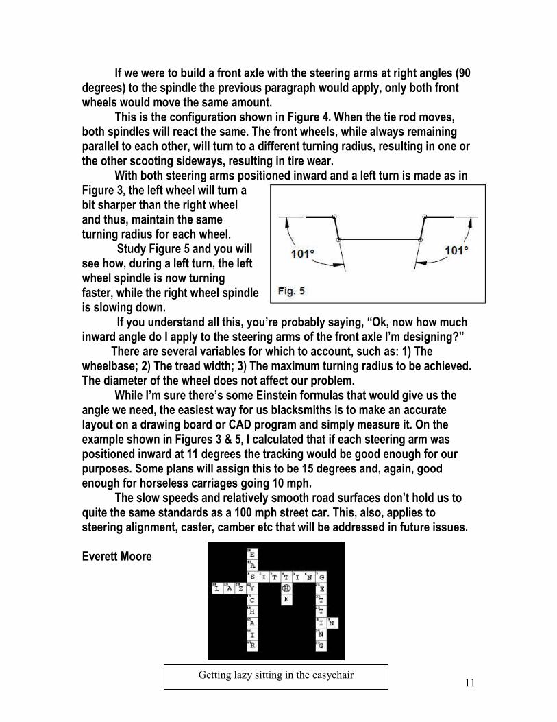
With both steering arms positioned inward and a left turn is made as in Figure 3, the left wheel will turn a bit sharper than the right wheel and thus, maintain the same turning radius for each wheel. Study Figure 5 and you will see how, during a left turn, the left wheel spindle is now turning faster, while the right wheel spindle is slowing down. If you understand all this, you’re probably saying, “Ok, now how much inward angle do I apply to the steering arms of the front axle I’m designing?” There are several variables for which to account, such as: 1) The wheelbase; 2) The tread width; 3) The maximum turning radius to be achieved. The diameter of the wheel does not affect our problem. While I’m sure there’s some Einstein formulas that would give us the angle we need, the easiest way for us blacksmiths is to make an accurate layout on a drawing board or CAD program and simply measure it. On the example shown in Figures 3 & 5, I calculated that if each steering arm was positioned inward at 11 degrees the tracking would be good enough for our purposes. Some plans will assign this to be 15 degrees and, again, good enough for horseless carriages going 10 mph. The slow speeds and relatively smooth road surfaces don’t hold us to quite the same standards as a 100 mph street car. This, also, applies to steering alignment, caster, camber etc that will be addressed in future issues. Everett Moore
Getting lazy sitting in the easychair

12
Building My First Car The 1903 Curved Dash Oldsmobile
Part 3 By
Terry Wright In the last issue of HCR Newsletter, I built my Kingpin and spindle assembly, and attached them to the axle. In this session, I will attach the axle to the springs. This is done by fabricating and using “spring perches” First: My front axle diameter is 2” OD, so for the part of the perch that will fit to the round axle tube, I used a 3 ¾” x 2” x ¼” flat bar. I inserted it into the drill press vise and drilled in the center with a 2” hole - saw.
Second: This gave me two halves that will neatly fit over the axle. Seen to the right is four pieces, one set for each front spring.
Third: I placed each pair onto a 5” length of ¼” x 2 ½” bar steel, (the same width as my springs). I then squared them into position for welding. Notice the 1 ½” x 3/8” slots in the bar steel. These will allow final adjustment, alignment of the axle.

13
Forth: I used short pieces of tubing the same size as the axle, to assist in alignment, holding everything in position while I spot-welded them in place onto the plates. Fifth: Here the completed perch is ready for mounting to the axle.
Sixth: I first attached the perch to the spring (both sides) with grade 8 bolts and nuts and I then positioned an angle locator on top of the steering yoke and set the caster of the axle at 10 degrees. Seventh: I then welded the perch to the axle. The front axle is now firmly attached to the springs and the caster is set. This should load up the tires with weight and help them go in a straight path.

14
Adding a bit of resistance when turning is good when you are steering with a tiller. It will tend to steer straight down the road hands off and will auto straighten itself when coming out of a turn. Next, I have to get the rear axle under the chassis. I will do that next Issue. Enjoy the build. Terry Wright How about that for a “step by step” description, builders. Terry, I feel that you are doing a great job on your CDO & also on the articles of your build…..:) Editor
Displaying Your HCR Carriage By
Gerry Hale
When attending car shows & displaying your HCR carriage, it is a lot of fun, answering all the questions folks ask, especially about carriages that not many folks living today are familiar looking at. It is however, nice to have some sort of display, featuring the technical information about the carriage, to refer to during conversations with onlookers. To also show how the wheels looked when I purchased them, I recently put this display stand together using a spare unused wheel & some bracing. This stand holds a poster board that features a picture of an original “Pie Wagon” with another showing my HCR Pie & pictures of when I was building it. Compartments for additional items, such as personalized cards or HCR brochures can be also added as I did at the top. The display board is to be used for the first time on Saturday February 27th at a local car show. Gerry

15
A Last Minute Update on the previous story
As I was getting ready to post the current issue, I received an E-Mail from Gerry with the following pictures. It turned out Gerry’s “Pie Wagon” took a “Judges Choice” award at yesterdays car show. He stated that “the show was plagued with rain most of the time during the event & the carriage stayed inside the trailer with the doors open for most of the show but I was however able to unload for a short time”.
Judging from the competition & limited exposure, I think Gerry did real good with his “Pie” HCR….:) Editor

16
“A Builder’s Candy Store” Chickasha, Oklahoma
PARTS PARTS PARTS Wheels, Axles, Frames, Complete Cars, Basket Cases
If you live in the central states & are considering building a HCR, then Chickasha, OK
Is the place to be on March 18 -19, 2010!
This will be my fourth year to attend the meet & have always returned home with great catches of parts for my builds at very, very reasonable prices. If you plan to attend this
March, let us know & we will try to get a group together…17 days left….:) Readers, Don’t forget to also read & download Stu’s article, “The Stu & Stanley Story”. It is a supplementary PDF file named “Volume2issue2a”… (in the Newsletter files) Enjoy & Keep Building! Lee