hot air welding guide for plastic repairs
TRANSCRIPT
HOT AIR WELDING GUIDE
FOR PLASTIC REPAIRS
Introduction
Most motor vehicles built today as well as many other modern products have components
made from plastics. For example, in automobiles and truck, bumpers, grilles, spoilers, light
surrounds and even complete body panels enable designers to enhance aerodynamic styling
and cosmetic appeal while retaining impact resistance and eliminating corrosion.
Plastic offers the structural strength of steel by virtue of its greater elasticity. Minor impacts
that could deform steel beyond repair can be absorbed by plastic. Where damage is incurred,
repair by welding is possible without a loss of component strength.
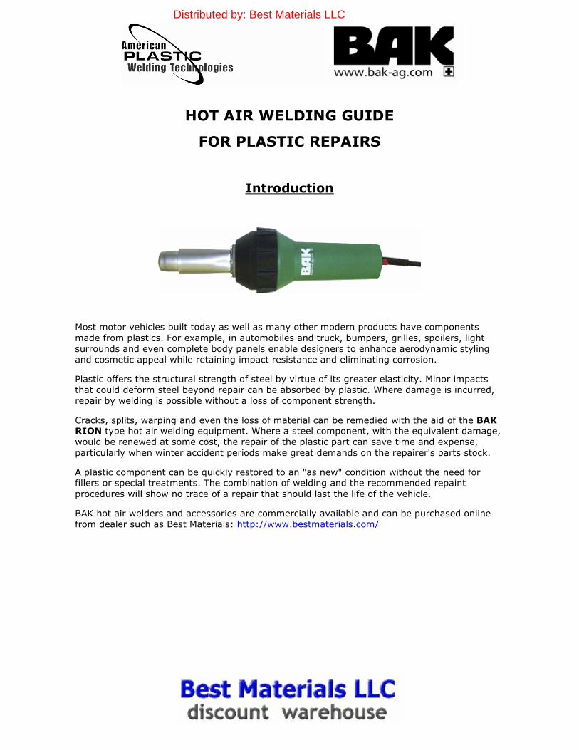
Cracks, splits, warping and even the loss of material can be remedied with the aid of the BAK
RION type hot air welding equipment. Where a steel component, with the equivalent damage,
would be renewed at some cost, the repair of the plastic part can save time and expense,
particularly when winter accident periods make great demands on the repairer's parts stock.
A plastic component can be quickly restored to an "as new" condition without the need for
fillers or special treatments. The combination of welding and the recommended repaint
procedures will show no trace of a repair that should last the life of the vehicle.
BAK hot air welders and accessories are commercially available and can be purchased online
from dealer such as Best Materials: http://www.bestmaterials.com/
Distributed by: Best Materials LLC
Identifying Plastics
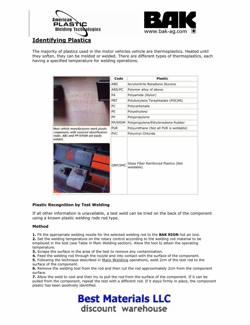
The majority of plastics used in the motor vehicles vehicle are thermoplastics. Heated until
they soften, they can be molded or welded. There are different types of thermoplastics, each having a specified temperature for welding operations.
Code Plastic
ABS Acrylonitrile Butadiene Styrene
ABS/PC Polymer alloy of above
PA Polyamide (Nylon)
PBT Polybutylene Terephtalate (POCAN)
PC Polycarbonate
PE Polyethylene
PP Polypropylene
PP/EPDM Polypropylene/Ethylenediene Rubber
PUR Polyurethane (Not all PUR is weldable)
PVC Polyvinyl Chloride
GRP/SMC Glass Fiber Reinforced Plastics (Not weldable)
Plastic Recognition by Test Welding
If all other information is unavailable, a test weld can be tried on the back of the component
using a known plastic welding rods rod type.
Method
1. Fit the appropriate welding nozzle for the selected welding rod to the BAK RION hot air tool.
2. Set the welding temperature on the rotary control according to the welding rod material to be employed in the test (see Table in Main Welding section). Allow the tool to attain the operating
temperature.
3. Scrape the surface in the area of the test to remove any contamination.
4. Feed the welding rod through the nozzle and into contact with the surface of the component. 5. Following the technique described in Main Welding operations, weld 2cm of the test rod to the
surface of the component. 6. Remove the welding tool from the rod and then cut the rod approximately 2cm from the component
surface.
7. Allow the weld to cool and then try to pull the rod from the surface of the component. If it can be
pulled from the component, repeat the test with a different rod. If it stays firmly in place, the component
plastic has been positively identified.
Appearance
Because plastic welding rod does not become completely molten, it may appear much the
same before and after welding. One accustomed to welding metal a plastic weld may see the
weld as appearing incomplete. The reason is that only the outer surface of the rod has
become molten while the inner core has remained hard. The welder is able to exert pressure
on the rod forcing it into the joint to create a permanent bond. When heat is taken away the
rod reverts to its original form. Thus, even though a strong permanent bond has been obtained
between the welding rod and base material, the appearance of the welding rod is much the
same as before the weld was made, except for molten flow patterns on either side of the bead.
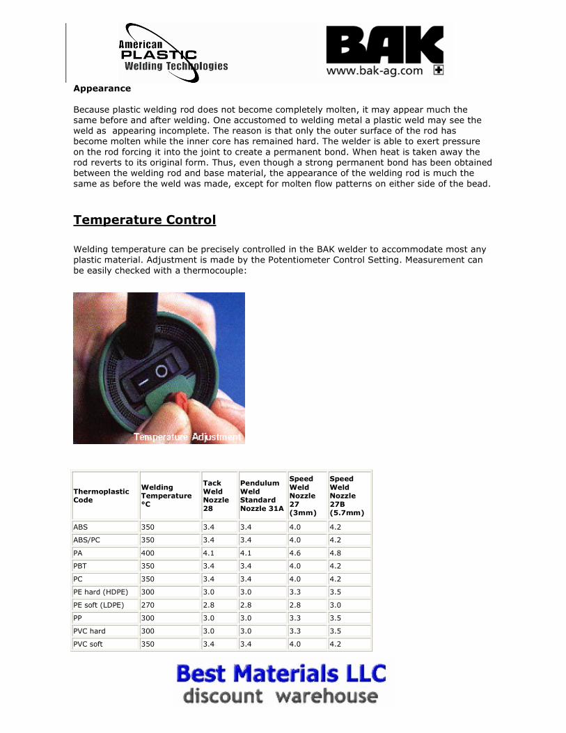
Temperature Control
Welding temperature can be precisely controlled in the BAK welder to accommodate most any
plastic material. Adjustment is made by the Potentiometer Control Setting. Measurement can
be easily checked with a thermocouple:
Thermoplastic Code
Welding Temperature °C
Tack Weld Nozzle
28
Pendulum Weld Standard
Nozzle 31A
Speed
Weld Nozzle
27 (3mm)
Speed
Weld Nozzle
27B (5.7mm)
ABS 350 3.4 3.4 4.0 4.2
ABS/PC 350 3.4 3.4 4.0 4.2
PA 400 4.1 4.1 4.6 4.8
PBT 350 3.4 3.4 4.0 4.2
PC 350 3.4 3.4 4.0 4.2
PE hard (HDPE) 300 3.0 3.0 3.3 3.5
PE soft (LDPE) 270 2.8 2.8 2.8 3.0
PP 300 3.0 3.0 3.3 3.5
PVC hard 300 3.0 3.0 3.3 3.5
PVC soft 350 3.4 3.4 4.0 4.2
Most all thermoplastics can be welded. The quality or ability to be welded is governed
by the extent of their melting range; those with the widest melting range are easiest to weld.
The two most popular thermoplastics for fabrication are polyvinyl chloride (PVC) and
polypropylene. Here is a list of plastic welding temperatures (in centigrade, when welded at
20C):
ABS 350ºC
Acrylic 350ºC
Hard PVC 220 - 300ºC
Hypalon 600ºC
Lucobit 600ºC
Polycarbonate 350ºC Polyethylene (Hard) 250 - 280ºC
Polyethylene (Soft) 270 - 300ºC
Polyisobutylene 600ºC
Polypropylene 300ºC
Polystyrol 250ºC
Polyvinylidene Fluoride 350ºC
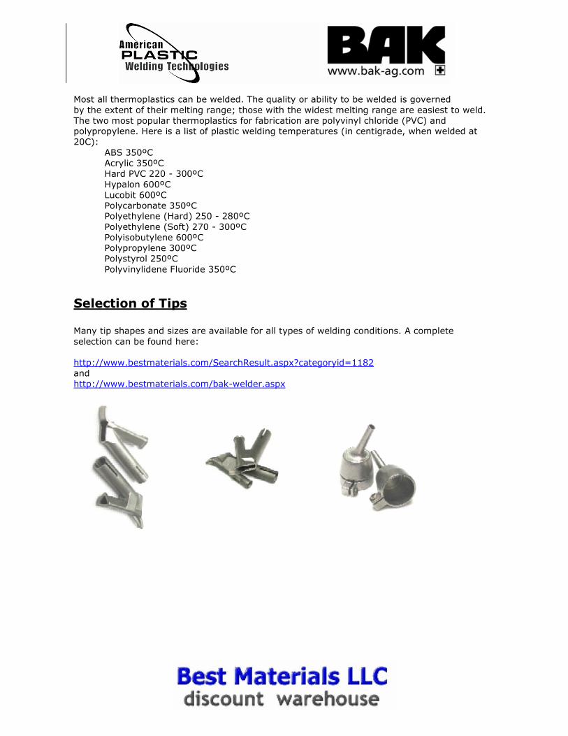
Selection of Tips Many tip shapes and sizes are available for all types of welding conditions. A complete
selection can be found here:
http://www.bestmaterials.com/SearchResult.aspx?categoryid=1182
and
http://www.bestmaterials.com/bak-welder.aspx
Surface Preparation
Simple preparation steps will insure successful repairs.
Plastic components can be repaired from the front or rear according to ease of access.
Reinforcement welds can be used across the rear of a front repair to restore strength to areas
designed to withstand impact. The photographs on the following web pages demonstrate a
repair on the front of a component.
If the damage passes behind a decorative or protective trim, this must be removed from the
damaged component to provide complete access to the repair area.
Trims are usually fixed with an adhesive that softens with heat treatment. Attempting to
remove a trim that is cold can damage it beyond repair.
The BAK RION hot air tool can supply 230 liters of air per minute at a precise temperature
between 20°C and 700°C. For trim removal, the hot air tool is used without a welding nozzle at
a temperature setting of 300°C. The temperature charts on the tool body show the rotary
control setting to achieve the correct air temperature.
Whenever the hot air tool is in use, the end of the element housing becomes extremely hot.
Always rest the tool on its stand when not in use.
Moving the hot air tool over the trip surface aids even heat absorption to soften the adhesive.
It also prevents localized heat build-up. When the adhesive is soft, the trip should pull away
neatly and allow for reuse after the repair.
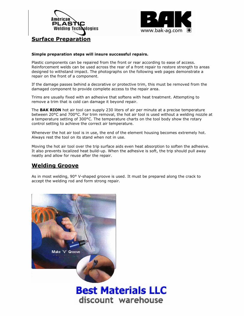
Welding Groove
As in most welding, 90° V-shaped groove is used. It must be prepared along the crack to
accept the welding rod and form strong repair.
Begin by removing any paint or other coating from the repair area with a body file or sander.
An area 10 to 15mm around the damage should be sufficient. If sections of the material have
been impacted and become trapped, the application of heat up to 200°C will help to free them.
A screwdriver blade can also be used to free trapped sections.
The 'V' groove can be formed with careful use of a square-edged file, but the best tool is a
rotary burring bit with a cutting edge on its circumference and end face. This creates the 90-
degree groove in one operation even following the most erratic of crack courses.
Begin the groove up to 10mm beyond the start of the crack and increase the depth
progressively to maximum by the time the start of the crack is reached. The depth of the
groove should be no more than 2/3 of the thickness of the material.
Best results are obtained when a high speed drill is employed. A slow drill or the use of a
single cutting face burring tool may lead to it jumping from the groove.
During the burring operations, always wear eye protectors and a dust mask to prevent
irritation from fine particles of plastic.
When the groove is finished, the welding rod for the material should rest neatly in it, the upper
curve face of the rod protruding 1 to 2 mm above the surface of the repair. This allows for
weld dressing operations, eliminating the need for fillers and ensuring enough depth of
penetration for the rod.
This test relates to larger components, such as bumpers, where a 5mm profile welding rod
should be used. If a 3mm welding rod is used, more than one run may be necessary. For small
or thin-walled components, one run of 3mm rod may be sufficient.
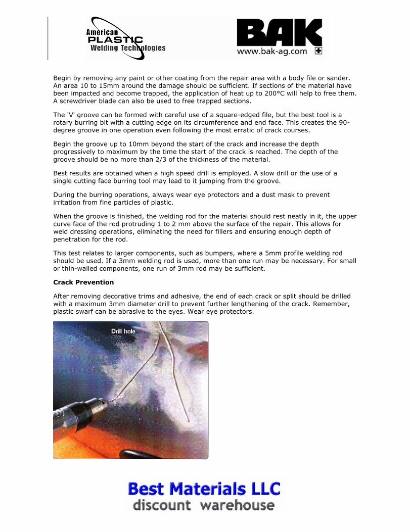
Crack Prevention
After removing decorative trims and adhesive, the end of each crack or split should be drilled
with a maximum 3mm diameter drill to prevent further lengthening of the crack. Remember,
plastic swarf can be abrasive to the eyes. Wear eye protectors.
Missing Material
Where small sections of plastic are lost, a piece can be used from a spare, unsalvageable part
of the same material. This can be shaped and inserted, though success will depend on the
availability of spare plastic, the intricacy of the design, and the experience of the operator.
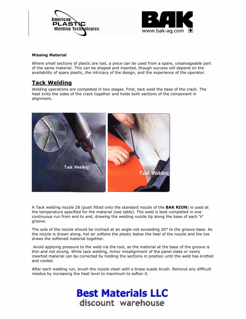
Tack Welding Welding operations are completed in two stages. First, tack weld the base of the crack. The
heat knits the sides of the crack together and holds both sections of the component in
alignment.
A Tack welding nozzle 28 (push fitted onto the standard nozzle of the BAK RION) is used at
the temperature specified for the material (see table). The weld is best completed in one
continuous run from end to end, drawing the welding nozzle tip along the base of each 'V'
groove.
The sole of the nozzle should be inclined at an angle not exceeding 20° to the groove base. As
the nozzle is drawn along, hot air softens the plastic below the heel of the nozzle and the toe
draws the softened material together.
Avoid applying pressure to the weld via the tool, as the material at the base of the groove is
thin and not strong. While tack welding, minor misalignment of the panel sides or newly
inserted material can be corrected by holding the sections in position until the weld has knitted
and cooled.
After each welding run, brush the nozzle clean with a brass suede brush. Remove any difficult
residue by increasing the heat level to maximum to soften it.
Main Welding
The most important rule in plastic welding is that it is only possible to weld like with like. Hence the need to identify the plastic material and select a matching welding
rod.
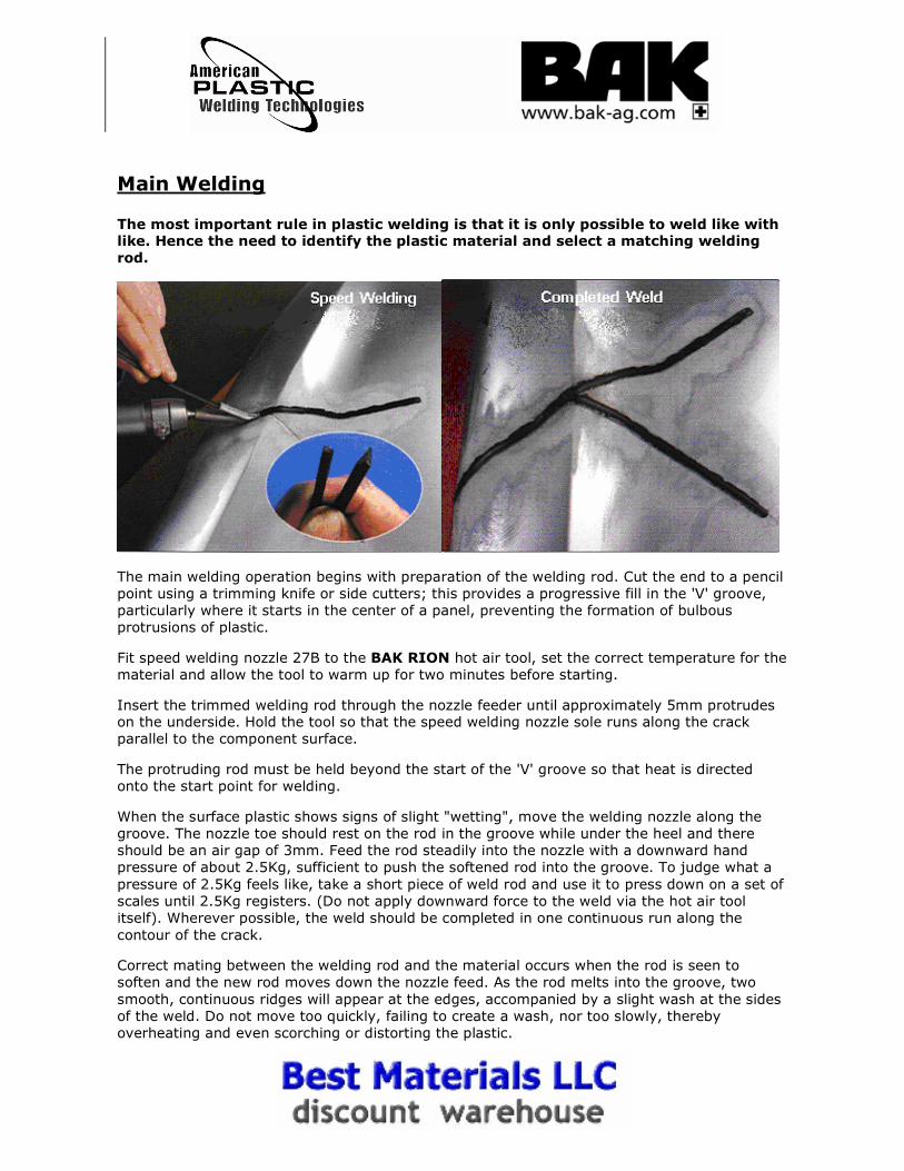
The main welding operation begins with preparation of the welding rod. Cut the end to a pencil
point using a trimming knife or side cutters; this provides a progressive fill in the 'V' groove,
particularly where it starts in the center of a panel, preventing the formation of bulbous
protrusions of plastic.
Fit speed welding nozzle 27B to the BAK RION hot air tool, set the correct temperature for the
material and allow the tool to warm up for two minutes before starting.
Insert the trimmed welding rod through the nozzle feeder until approximately 5mm protrudes on the underside. Hold the tool so that the speed welding nozzle sole runs along the crack
parallel to the component surface.
The protruding rod must be held beyond the start of the 'V' groove so that heat is directed
onto the start point for welding.
When the surface plastic shows signs of slight "wetting", move the welding nozzle along the
groove. The nozzle toe should rest on the rod in the groove while under the heel and there
should be an air gap of 3mm. Feed the rod steadily into the nozzle with a downward hand
pressure of about 2.5Kg, sufficient to push the softened rod into the groove. To judge what a
pressure of 2.5Kg feels like, take a short piece of weld rod and use it to press down on a set of
scales until 2.5Kg registers. (Do not apply downward force to the weld via the hot air tool
itself). Wherever possible, the weld should be completed in one continuous run along the
contour of the crack.
Correct mating between the welding rod and the material occurs when the rod is seen to
soften and the new rod moves down the nozzle feed. As the rod melts into the groove, two
smooth, continuous ridges will appear at the edges, accompanied by a slight wash at the sides
of the weld. Do not move too quickly, failing to create a wash, nor too slowly, thereby
overheating and even scorching or distorting the plastic.
When the weld has been completed, remove the hot air tool, sliding the nozzle off the
remaining welding rod. Once cool, the unwelded rod end is cut off as close to the weld as
possible.
The completed weld appears as a smooth, continuous line with the wash still visible alongside
it, confirming that the rod has welded successfully with the component.
During the welding, previously unseen cracks may open up. These are not new but are impact
cracks that have been present since the initial damage. These must be treated and welded as
any other crack damage.
If the weld is successful, reinforcement welds can be added to the reverse of the material
across the axis of the repair. The same preparation and weld operations apply.
Pendulum Welding
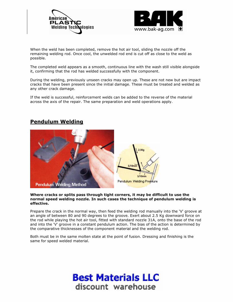
Where cracks or splits pass through tight corners, it may be difficult to use the
normal speed welding nozzle. In such cases the technique of pendulum welding is
effective.
Prepare the crack in the normal way, then feed the welding rod manually into the 'V' groove at an angle of between 80 and 90 degrees to the groove. Exert about 2.5 Kg downward force on
the rod while playing the hot air tool, fitted with standard nozzle 31A, onto the base of the rod
and into the 'V' groove in a constant pendulum action. The bias of the action is determined by
the comparative thicknesses of the component material and the welding rod.
Both must be in the same molten state at the point of fusion. Dressing and finishing is the
same for speed welded material.
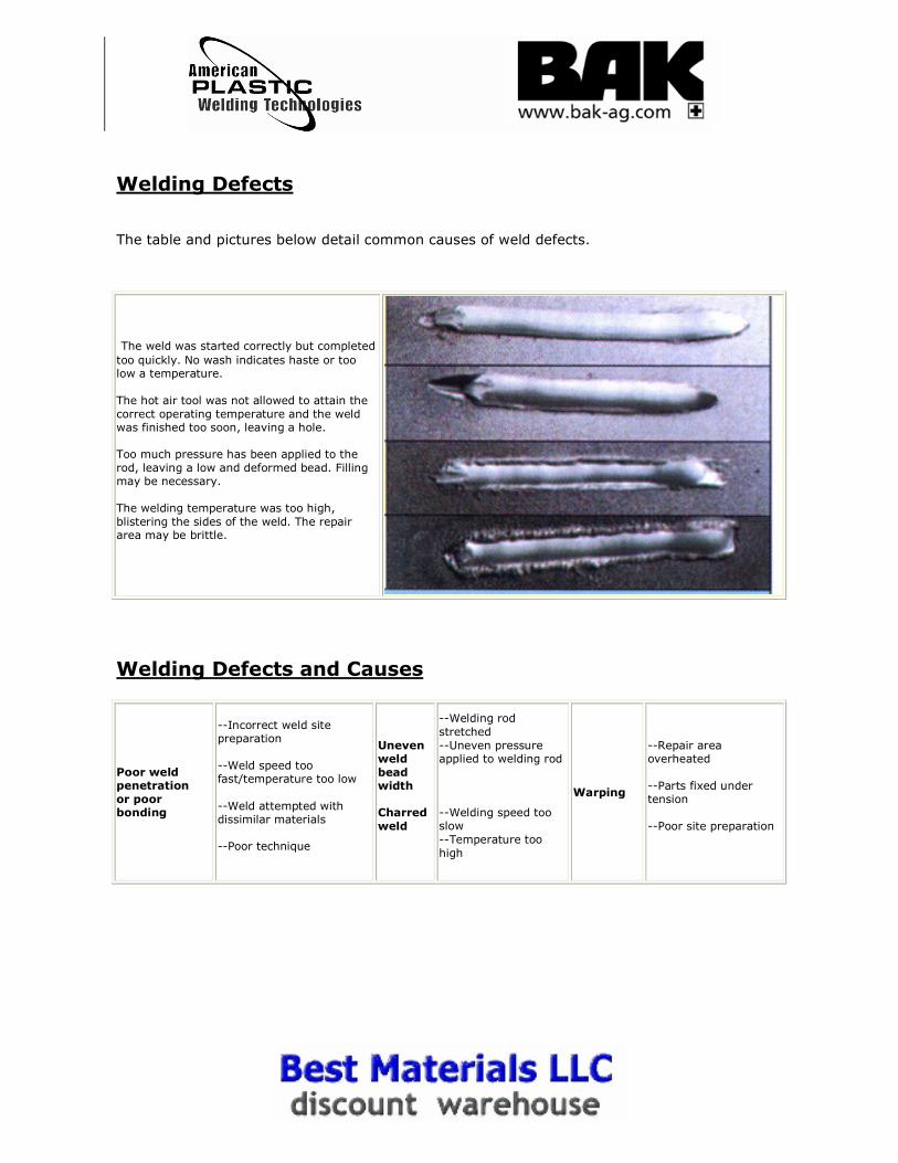
Welding Defects
The table and pictures below detail common causes of weld defects.
The weld was started correctly but completed
too quickly. No wash indicates haste or too low a temperature.
The hot air tool was not allowed to attain the
correct operating temperature and the weld was finished too soon, leaving a hole.
Too much pressure has been applied to the
rod, leaving a low and deformed bead. Filling may be necessary.
The welding temperature was too high,
blistering the sides of the weld. The repair area may be brittle.
Welding Defects and Causes
Poor weld penetration
or poor bonding
--Incorrect weld site preparation
--Weld speed too fast/temperature too low
--Weld attempted with dissimilar materials
--Poor technique
Uneven weld
bead width
Charred
weld
--Welding rod
stretched
--Uneven pressure applied to welding rod
--Welding speed too slow
--Temperature too
high
Warping
--Repair area overheated
--Parts fixed under tension
--Poor site preparation
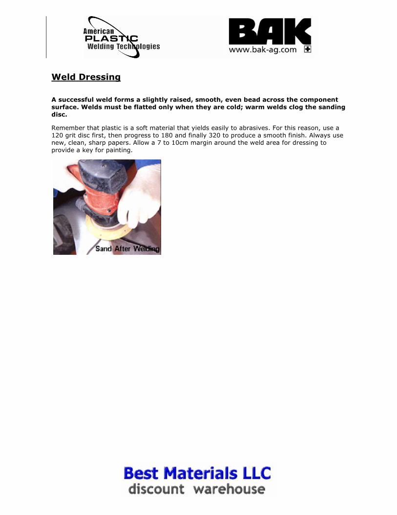
Weld Dressing
A successful weld forms a slightly raised, smooth, even bead across the component
surface. Welds must be flatted only when they are cold; warm welds clog the sanding
disc.
Remember that plastic is a soft material that yields easily to abrasives. For this reason, use a
120 grit disc first, then progress to 180 and finally 320 to produce a smooth finish. Always use new, clean, sharp papers. Allow a 7 to 10cm margin around the weld area for dressing to
provide a key for painting.
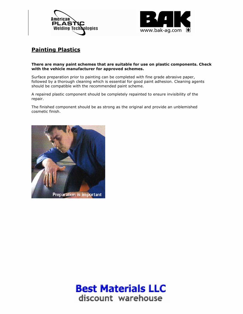
Painting Plastics
There are many paint schemes that are suitable for use on plastic components. Check
with the vehicle manufacturer for approved schemes.
Surface preparation prior to painting can be completed with fine grade abrasive paper,
followed by a thorough cleaning which is essential for good paint adhesion. Cleaning agents
should be compatible with the recommended paint scheme.
A repaired plastic component should be completely repainted to ensure invisibility of the
repair.
The finished component should be as strong as the original and provide an unblemished
cosmetic finish.