hot forming tribology
TRANSCRIPT

LICENTIATE T H E S I S
Department of Engineering Sciences and MathematicsDivision of Machine Elements
Hot Forming Tribology: Galling of Tools and Associated Problems
Leonardo Pelcastre
ISSN: 1402-1757 ISBN 978-91-7439-308-8
Luleå University of Technology 2011
Leonardo Pelcastre Hot Form
ing Tribology: G
alling of Tools and Associated Problem
s
ISSN: 1402-1757 ISBN 978-91-7439-XXX-X Se i listan och fyll i siffror där kryssen är


Hot Forming Tribology:
Galling of Tools and Associated Problems
Leonardo Pelcastre
Luleå University of Technology
Department of Engineering Sciences and Mathematics
Division of Machine Elements

Printed by Universitetstryckeriet, Luleå 2011
ISSN: 1402-1757 ISBN 978-91-7439-308-8
Luleå 2011
www.ltu.se

Metallurgist:
A pseudo scientist, who uses undetermined suppositions, indefinite theories, and inexpressible hypotheses; which are based on unreliable information, uncertain quantities, and incomplete data; derived from non-reproducible experiments and incomplete investigations; using equipment and instruments of questionable accuracy, insufficient resolution, and inadequate sensitivity, to arrive at tentative cloudy, abstruse, and non-committed conclusions prefaced by the phrase,
"IT DEPENDS"


I
Preface
This thesis summarises the work I have carried out during the first part of my PhD at the Division of Machine Elements at Luleå University of Technology.
I firstly would like to thank my supervisors Professor Braham Prakash and Dr. Jens Hardell for their guidance, support and help in my research. As a Materials Engineer, starting on the field of Tribology was a challenge, but their support has made the transition easier.
I would also like to thank the Centre for High-performance Steels (CHS) for the financial support as well as Gestamp HardTech and Accra Teknik AB/Linde+Wiemann. At the same time, I want to thank Katarina Eriksson and Erik Adolfsson at Gestamp HardTech, Göran Berglund at Accra Teknik AB and Dr. Per Hanson at SSAB for the interesting research questions as well as their active interest in the research.
I am grateful to my colleagues at the Division of Machine Elements and to my friends for making an enjoyable atmosphere to work in.
Finally, I would like to thank my family and girlfriend Emily for their encouragement. Doing this work away from those you love can be a challenge at times, but I am grateful for their patience and continuous support.
Leonardo Pelcastre
Luleå, August 2011

II
III
Abstract
In recent years, the use of ultra high-strength steels (UHSS) as structural reinforcements and in energy-absorbing systems in automobiles has increased rapidly; mainly in view of their favourable strength to weight ratios. However, due to their high strength, the formability of UHSS is poor, thus complex-shaped UHSS components are invariably produced through hot-metal forming processes. The use of hot stamping or press hardening, which was developed during the 1970’s in northern Sweden, has become increasingly popular for the production of ultra high strength steels.
In hot stamping, different tribological problems arise when the tool and work-piece interact during the forming process at elevated temperatures. Wear and surface damage of forming tools can be detrimental to the quality of the final product and these can also have an adverse impact on the process economy due to frequent maintenance or replacement of tools.
In this work, a literature review pertaining to tribology of hot sheet metal forming has been carried out. This review has revealed that the awareness of tribology and its application in metal forming processes at high temperature has increased in the recent years. A considerable amount of work has been done to enhance the understanding of the response of different materials and parameters involved and also to improve the process itself. However, despite these developments, there exist major gaps in knowledge pertaining to the occurrence of friction and wear in hot sheet metal forming.
Extensive experimental studies have thus been undertaken to bridge some of the knowledge gaps related to tool wear and failure mechanisms in the hot stamping process. These studies have involved both the systematic analysis of actual worn tools as well as parametric tribological investigations in the laboratory.
The analysis of worn tools showed that friction is a crucial parameter in their operating life. It was observed that severe mechanical stresses are generated due to high friction during the work-piece/tool interaction. As a result of the cyclic thermal and mechanical loads imposed during the hot forming process, the stresses generated eventually lead to the occurrence of fatigue damage at the tool surface. Another important mechanism observed was material transfer from the work-piece to the tool surface. This is particularly common and detrimental in hot forming of coated work-piece material. The most common coating applied to the ultra high strength steel is a hot dip aluminium based coating, commonly referred to as Al-Si coating.
The parametric studies carried out were aimed at understanding of the initiation mechanisms of material transfer from the Al-Si coated steel to the tool material. The results showed that severe galling occurs by accumulation and compaction of wear debris and becomes enhanced in tools having rough surfaces. The roughness defects on the surface promote accumulation of wear particles. Furthermore, high contact pressure also enhances the compaction of wear debris and consequently the severity of material transfer. It was observed that the severity of galling can be reduced by the use of smooth and hard surfaces.
Additionally, the use of different PVD coatings on the tool steels showed an increased tendency on adhesion, causing a severe material transfer onto the tool surface.

IV

V
Appended papers
- Paper A
L. Pelcastre, J. Hardell, N. Herrera and B. Prakash. Investigations into the failure mechanisms of form fixture hardening tools. Presented at the CHS2 conference, June 2011and to be submitted for journal publication.
- Paper B
L. Pelcastre, J. Hardell and B. Prakash. Investigations into the occurrence of galling during hot forming of Al-Si coated high-strength steel. Proc. IMechE. Part J: J. Engineering Tribology 225 (2011) 487-498
- Paper C
L. Pelcastre, J. Hardell and B. Prakash. Exploration of techniques for the alleviation of galling during hot forming of Al-Si coated ultra high-strength steels. To be submitted for journal publication.

VI

VII
Table of Contents
1. Introduction ............................................................................................................................... 1
1.1 High temperature tribology .................................................................................................... 1
1.2 Tribology in hot metal forming .............................................................................................. 2
1.3 Hot sheet metal forming processes ......................................................................................... 4
1.4 Tribological effects of the work-piece material ..................................................................... 5
1.5 Tribological issues in hot forming.......................................................................................... 7
1.6 Surface engineering ................................................................................................................ 8
1.7 Existing research gaps .......................................................................................................... 10
2. Aims of this work .................................................................................................................... 11
2.1 Specific objectives ................................................................................................................ 11
3. Experimental materials and test procedure ......................................................................... 13
3.1 Materials ............................................................................................................................... 13
3.1.1 Paper A .......................................................................................................................... 13
3.1.2 Paper B .......................................................................................................................... 14
3.1.3 Paper C .......................................................................................................................... 15
3.2 Experimental procedure ....................................................................................................... 17
3.2.1 Paper A .......................................................................................................................... 17
3.2.2 Paper B .......................................................................................................................... 18
3.2.3 Paper C .......................................................................................................................... 19
4. Salient results .......................................................................................................................... 21
4.1 Failure mechanisms of form fixture hardening tools (Paper A) ........................................... 21
4.2 Occurrence of galling (Paper B) ........................................................................................... 24
4.2.1 Effect of tests parameters .............................................................................................. 26
4.2.1 Mechanisms for the formation of the transferred layer ................................................. 29
4.3 Exploration of ways for galling alleviation (Paper C) .......................................................... 30
5. Conclusions .............................................................................................................................. 35
6. References ................................................................................................................................ 37
Appended papers
Paper A ....................................................................................................................................... 41
Paper B ....................................................................................................................................... 55
Paper C ....................................................................................................................................... 69

VIII

1
Chapter 1
Introduction
With the introduction of new regulations for the control of CO2 emissions, the demand for reduction of weight in vehicles has increased. This, coupled with the enhanced safety requirements, has necessitated the introduction of light weight materials and particularly ultra high strength steel (UHSS) in automobiles on a large scale. The use of UHSS enables in significant reduction in weight of the automobiles without sacrificing the structural strength and safety requirements.
In view of the very high strength of UHSS, the components are usually formed at high temperatures (~950ºC) in a process known as hot stamping. This process facilitates forming of complex shaped parts owing to the low yield stress of the steel at high temperatures. It also provides a good dimensional control of the produced parts. The most important aspect of this process is that forming and quenching of the steel component are done simultaneously, thus accomplishing the desired mechanical properties for the UHSS parts.
The hot stamping process also involves several problems. These are mainly due to the tribological interaction of the UHSS work-piece and tool at elevated temperatures. Problems such as material transfer, surface initiated fatigue, wear and high friction are commonly encountered in the hot forming process.
Over the last few years, research has been carried out to overcome these issues in the hot stamping process. However, a lot of work still needs to be done to clearly identify, understand and solve problems related to these phenomena.
1.1 High temperature tribology
The term ‘high temperature’ can be easily misinterpreted. There is no specific limit that can be identified as high or low temperature and it mainly depends on the particular application and the materials involved.
Take for instance the case of polymers, metals or ceramics. Commonly, these materials operate in different temperature ranges. For several polymers, temperatures about 150-200ºC are high temperatures, as at these temperatures they start to deteriorate. For ceramics, the temperatures they can withstand are significantly higher. Metals on the other hand can be used in a wide range of temperatures.
In tribological applications, a system can be considered to operate at elevated temperatures when conventional lubrication cannot be used which is at temperatures around 300ºC. Under these conditions, there are many physical and chemical processes taking place at the same time such as oxidation, frictional heating, occurrence of wear due to the interaction between the different parts in relative motion, thermal softening, diffusion, microstructural changes among others. The occurrence of such complex
2
phenomena makes tribology at elevated temperatures a highly challenging field of research.
1.2 Tribology in hot metal forming
There are many machines, components and processes that operate at high temperatures. Some examples are components used in the aerospace, power generation or metal forming industries. Metal forming has been known for centuries, however, the variety of metal forming processes is wide and there are still several unknown phenomena particularly when it comes to the tribology of the different processes.
Friction is desirable in most hot metal forming operations. In rolling for example, it allows the metal to be drawn into the gap between the rolls, in open-die forging it prevents the metal escaping from between the tool dies and in closed-die forging it provides the back pressure in the flash to ensure filling of the die cavity. However in some other forming applications, like extrusion, friction may be desirable at a low level to keep the forming pressure low. From these examples it is clear that friction in metal forming is not to be at low levels nor at high levels. An optimum friction level which balances the load (energy) and the forming conditions is needed.
Actual forming process is difficult to simulate in the laboratory for several reasons. One of the main problems involved in laboratory tests is the forming speed which tends to be high and difficult to control under laboratory conditions. Another problem in simulating forming processes is the surface topography of both the tool and the work-piece which is hard to replicate. The interaction between the two surfaces and the formed oxide and debris layers is constantly changing and strongly affected by the forming conditions. Thus the details of the events occurring are poorly understood. In a review by Beynon [1] he states that what is needed is a computer-based model of the interface, supported by whatever sparse information is available. Such a model would help in defining the constitutive behaviour of the interface.
Despite the need and absence of such a model, or the lack of understanding of the tribological processes, different fundamental studies concerning materials of interest in the field of metal forming have been carried out. For instance Vergne et al. studied the influence of oxides on friction in hot rolling [2]. They proposed that oxides which are not very adherent to the strip or the rolls could be beneficial in reducing friction as long as they are soft. These contribute to the reduction of the coefficient of friction by forming a third body able to accommodate the shear. Adherent oxides, irrespective of whether they are soft or hard, contribute to increased shear stresses and friction. In this case, wear occurs by abrasion or by oxide spalling. They did interrupted tests to identify the influence of the oxides formed during the different stages at which the coefficient of friction changes. High friction was observed at the beginning of the tests, attributed to the shearing forces necessary to break the initial micro junctions between the passive oxide scale of the pin (considered as metallic) and the disc surface oxidised at high temperature. The formation of the third body, generated by attrition of the oxidised carbides and transfer to the disc surface, led to decreased friction coefficient. When the debris coming

3
from the pin mixed with the constantly growing oxide of the disc (work piece) the contact became iron oxide-iron oxide which led to an increase in friction. When this contact was fully established, friction stabilised. They found that the contribution of the alloying elements of the work roll grade is sensitive only in the running in part of the friction curve.
Pellizzari et al. have also carried out experiments to understand the tribological behaviour of materials related to hot rolling [3]. In one of their studies they evaluated the high temperature friction and wear behaviour of high speed steel and high chromium iron. The tribological tests were carried out by means of a disc on disc rig which gives rolling-sliding conditions. They found that the wear occurred by abrasion, adhesion and triboxidation mechanisms. Abrasion of the roll materials was caused by the oxide scale developing on the hot carbon steel counterpart. Its abrasive action was enhanced by transfer of hard particles from the roll. They also concluded that wear is not the simple summation of individual mechanisms, but rather a rate process. However, such rates are not definable and the author suggests that further research needs to be performed in this field.
Oxides in general have a very significant influence on the tribological behaviour at high temperatures; the occurrence of oxidation can have both a protective effect and a detrimental effect. Quinn has done several studies concerning the oxidational wear where he also proposed a model for this type of wear [4- 7]. His studies contributed significantly to the understanding of the oxidational wear, with a model called the General Theory of Oxidational Wear. The tribological activation energies for oxidation can be deduced, which is about half the value of the static oxidation.
In metal forming operations the formation of different tribolayers is of great importance as they strongly influence wear and friction. Studies of the impact of tribolayers formed at high temperature have increased in recent years. Jiang et al. [8] proposed a model to explain how the tribolayers are formed. They proposed that wear debris can be either trapped within the grooves caused by wear, or be removed from the tribosystem. The trapped debris will then change the tribological response. If the debris is hard it can act as free moving particles and result in abrading action. The particles may also be comminuted during the sliding and form wear-protective layers. Oxidational environment also facilitates the consolidation of these layers due to chemical sintering effect between the particles.
Several researchers [9- 17] have also found that the particles entrapped during the sliding motion form compacted layers. The work reported in the open literature includes studies done at low temperatures, but this aspect is more significant at high temperatures. It has been found that when the protective layers are formed the wear rate is reduced and the friction becomes more stable. However when break down of such layers occurs, it results in increased friction and wear. What is not known is under which conditions such break down occurs.
4
Transitions from severe to mild wear and mild to severe wear are commonly encountered in metallic systems [18- 20]. The transition has been linked to the continuous formation and failure of the layers formed during sliding. In one of their studies, Pauschitz et al. [20] stated that the tribolayers can be distinguished according to their mechanical properties, physical appearance, chemical composition and failure mechanisms. In their studies they distinguished between four possible situations: No Layer formation (NL), Transfer Layer formation (TL), Mechanically Mixed Layer formation (MML) and Composite Layer formation (CL)
They proposed that the formation of these tribolayers depend on the wearing conditions, wearing material and mating material. The tribolayers determine the friction coefficient and wear rate. At near ambient temperature, it can either be NL formation or TL formation. When the hardness of the mating surface is significantly higher than the hardness of the wearing surface, NL is formed. At relatively higher temperature, or under condition of relatively soft but comparable hardness of the surfaces in contact, MML is formed. The chemical state of such a layer is characterized by low oxygen content and composition is in between the composition of the wearing sample and the composition of the mating material. At high temperature, CL is found. The composition of the worn surface with CL and the composition of the wear debris will be in between the composition of the wearing sample and the composition of the mating surface. In addition, CL contains high amount of oxygen. This makes the layer hard and brittle. This leads to higher friction coefficient and lower wear rate. The interface between the CL and the substrate is very weak, giving rise to detachment of the layer at the interface. The strength of this interface improves with increase in temperature
1.3 Hot sheet metal forming processes
The usage of hot stamping, a type of hot forming process, for manufacturing of UHSS structural and safety components of automobiles has increased in the recent years.
The hot stamping or press hardening process was developed during the 1970’s in northern Sweden. The process involves heating a steel blank in a furnace above the austenitisation temperature and after a holding time at this temperature, the sheet material is transferred to a press tool where it is formed and subsequently quenched. The advantage of this process is that the forming occurs when the steel blank is in the austenite phase. This improves the formability and enables manufacturing of complex shaped components. The subsequent quenching stage results in a martensitic structure which imparts good mechanical properties of the steel parts.
Two different processes are normally used for hot stamping: direct and indirect. Direct hot stamping involves heating the sheet material, forming and quenching. In the indirect method the sheet material is formed in the cold state, then heated and transferred into another tool for final forming and then quenched. For the indirect method uncoated blanks are usually applied [21]. The direct method is used for UHSS with different coatings. The most commonly used coating is a hot dip Al–Si coating. Figure 1 shows a schematic of the hot stamping process in its two versions.

5
Figure 1. Schematic representation of the hot stamping process variants. From [22]
1.4 Tribological effects of the work-piece material
The steels that are normally used for hot sheet metal forming processes are ultra high strength boron steels (UHSS). These steels are well known for their good hardenability. A boron addition of 30 ppm gives a hardenability increases equivalent to 0.6% Mn, 0.7% of Cr, 0.5% of Mo or 1.5% of Ni [22]. After heat treatment or hot stamping this steel exhibits more than 1500 MPa ultimate tensile strength and 1100 MPa yield strength. Boron delays the ferrite and pearlite transformations during the processing while the martensite and bainite transformations are not influenced [23].
A common problem encountered with these steels, however, is the formation of oxide scale when heating. This requires an additional cleaning step for removing the oxide scale. Another problem is the decarburization of the steel when it is heated up. To overcome these problems, a coating of Al and Si is often applied. During heating, the Fe from the substrate and the Al and Si from the coating inter-diffuse to form intermetallic compounds. The composition of the intermetallics varies across the coated layer and it depends on the holding time at high temperature [24, 25]. The resulting coating not only prevents the formation of oxide scale and decarburization but also provides good corrosion resistance, good weldability and a suitable surface for painting [25].
Some investigations on the high temperature tribological properties of Al–Si-coated UHSS during sliding against different tool steels with and without surface treatment/coating have been done [24, 26- 31]. It has been observed that the application of an Al–Si coating on the UHSS decreases friction at elevated temperatures as a result of reduced adhesive component of friction. Since the intermetallic layer on the UHSS is very hard, it also induces more wear on the mating tool steel surface as a result of abrasive wear. In a study done by Yanagida et al. [30] they investigated the friction behaviour of two sheet materials as a function of temperature and die pressure when

6
sliding against typical hot forming tool steel under dry and lubricated conditions. They found that the Al-Si coated sheet material experienced higher friction compared to the uncoated in both dry and lubricated conditions. They also concluded that lubrication is an effective way to reduce friction and consequently the loads on the dies. In a different study carried out by Dessain et al. [29] they also evaluated the friction behaviour of Al-Si coated UHSS and found that friction was marginally affected by temperature and contact pressure.
When uncoated work-piece is used, the occurrence of abrasive wear of tool can be severe; especially in the case of direct hot stamping process which involves large relative sliding between the tool and the work-piece [21]. In a study carried out by Hardell et al. [24] it was observed that the wear is also dependant on temperature. They observed that low temperature resulted in high wear of the tool steels and this was reduced at high temperatures. At high temperatures, different wear mechanisms have been observed during the interaction of Al-Si coated ultra high strength steel and tool materials. However, the principal wear mechanism at high temperature appears to be adhesive wear and material transfer coupled with abrasion from debris at elevated temperatures [27].
In one of their papers [26], Hardell et al. stated that the frictional behaviour of tool steel and UHSS pairs can be modified through the use of surface coating and/or treatment applied on one or both surfaces. The surface layer composition of the sheet material (i.e. coating on the sheet) has a much bigger influence on the friction level compared to nitriding and/or coating of the tool steel. This effect can be seen in Figure 2.
Figure 2. Coefficient of friction as a function of sliding distance for new tool steel specimens sliding against (a) uncoated UHSS, (b) Al-Si coated UHSS and (c) Al-Si + graphite coated UHSS. From [26]
The work-piece coating most commonly used in hot sheet metal forming is the Al-Si coating. This coating can, however, be problematic as it generates severe material transfer to the tool. Some alternatives have been looked into and one of these is the use of galvanic zinc based coatings. In a study done by Kondratiuk et al. [31], the friction and wear behaviour of a Zn-Ni coating was analysed vis-à-vis that of the Al-Si coating. It was observed that the friction coefficient was lower when Zn-Ni coating was used. This was mainly attributed to the formation of zinc oxides on the surface. In terms of wear, reduced material transfer was also observed for the Zn-Ni coating which was also attributed to the
(a) (b) (c)

7
presence of zinc oxides. They also suggested that increasing the temperature at which the blank is austenitised reduces the material transfer in the case of Al-Si coating.
1.5 Tribological issues in hot forming
In the hot stamping process, not only the control of friction is important but also the control of wear and principally the wear of the tools as tooling constitutes high costs of the stamping process. The interaction between the tools and the work-piece is strongly influenced by the tribological properties at the interface. Damage or excessive wear of the tools can be detrimental to the quality of the final component and it also has an impact on the process economy due to maintenance or replacement of tools. Common problems encountered in the metal forming operations are galling (material transfer), wear of tools and thermal and mechanical fatigue.
When Al-Si coated steels are employed in the forming process, beneficial effects have been found such as decreased friction due to reduced interfacial shear [24, 26, 27]. However, various problems can also arise. During heating, the coating is known to stick to the rollers in the furnace [28] but even more important is the fact that during forming there is a severe transfer of coating to the tools which result in built-up material. This phenomenon is also known as galling.
A review of recent work has shown that there is very little information available in the open literature concerning galling at elevated temperatures despite its significance in hot forming. Most of the earlier studies have focussed on the galling mechanisms at low (room) temperatures. Some studies have highlighted the role of surface roughness or surface defects as these can act as galling initiation sites. Smooth surfaces have shown better performance both in dry and lubricated contacts [32- 34]. The hardness and surface engineering of the tool materials have also been reported to influence the galling process [32, 35]. In lubricated contacts, it is not only the surface roughness but also the interfacial temperature that plays an important role in the occurrence of galling. It has been found that improved heat dissipation enhances the galling resistance [35]. Gåård et al. [36] reported that when temperature increases, the sliding distance before occurrence of severe adhesive wear decreases.
There are problems that are linked to the occurrence of friction and wear during tool and work-piece interaction and also those associated with the elevated temperatures. The thermal and mechanical loads experienced by hot forming tools can result in serious degradation processes such as oxidative wear, thermal fatigue, plastic deformation and cracking. These gradually cause the tools to lose their original geometry and thus they must be either refurbished or replaced.
Mechanical and thermal fatigue are important damage mechanisms which are encountered in hot forming tools [37- 41]. Their initiation mechanisms are different and the sensitivity to either of these two mechanisms depends on the process. In a study carried out by J. Sjöström and J. Bergström [38] they found that thermal fatigue was the

8
primary mechanism in die-casting and hot forging tools and the initiation of cracks could occur within 1% of the tool life.
Given the extreme and harsh conditions to which the tools are subjected in hot metal forming processes, the quality and the properties of the tool materials are extremely important. It is necessary to optimise the combination of hardness and toughness to provide the tools with adequate wear life and fatigue resistance. In a study carried out by A. Persson et al. [42], the importance of the properties of the tools and also on the influence of surface engineering methods on the sensitivity to thermo-mechanical fatigue have been emphasised.
1.6 Surface Engineering
As the performance of machines is continuously increasing, the demands put on the engineering materials are more demanding than ever. This leads to a point where the performance for certain applications cannot be fulfilled by means of only the intrinsic properties of a bulk material alone. One example of this is the hot metal forming operation. It is a requirement for the tool materials to be wear resistant which is in general associated with hardness, but at the same time, it needs to have high toughness to resist the mechanical response during the process as well as resistance to fatigue. The other requirements are the resistance to oxidation corrosion.
All of these requirements cannot be fulfilled by only the bulk material, instead the use of surface engineering technologies to impart certain properties on the surface of the material are needed. Surface engineering (or more broadly surface modification) technologies are essentially employed to modify the surface and near surface properties of a substrate materials by means of surface treatments or coatings. In a surface engineered material, the mechanical strength is given by the bulk material but properties like wear resistance or oxidation resistance are enhanced with the use of surface treatments and/or coatings. Today numerous methods for surface treatments and coatings are available and a very careful selection of the most appropriate method for a specific application is required.
In recent years, several studies have been carried out to evaluate the efficiency of different coatings and surface treatments in the field of hot forming. In an investigation done by Özgür et al. [43], the wear performance and thermal diffusivity properties of M41 tools steel with various coatings were studied. The coatings evaluated were TiN, TiAlN, AlTiN, CrN and TiCN. In general, the coatings had good performance in terms of abrasive wear but TiAlN and AlTiN had superior wear resistance. They found that the wear of the coated specimens decreases with increasing micro-hardness. The CrN coated sample having the lowest microhardness showed very high wear whereas the AlTiN with highest microhardness resulted in lowest wear (Figure 3).

9
Figure 3. The total mass loss variations of a) coated samples for 8000 m and wear distance and b) Micro-hardness values for surface coatings
The coatings that performed well according to the thermal diffusivity values were TiAlN and AlTiN coatings. They found that the TiAlN coating which had the lowest thermal diffusivity and highest micro-hardness value was the most wear resistant. Such properties are useful in applications such as cutting. They conclude that the heat accumulation on a cutting tool can be decreased with decreasing thermal conductivity.
Another aspect to be considered is the process for deposition of the coating. It has been found that coatings differ in terms of their wear resistance when they are applied as a single layer process or as multi-layers. In different studies on the TiAlN coatings, it has been found that the wear resistance at high temperatures is enhanced when multilayered coatings are used. In a study by Rodriguez-Barracaldo et al. [44], they studied the influence of single and duplex PVD coating. They found that at high temperatures, the single layered (TiAl)N PVD coating showed the highest wear volume and attributed this effect to the limited load-carrying capacity of the system. It does not prevent the substrate from deforming plastically and to cause brittle fracture of the PVD film.
In a study done by J. Hardell et al. [45] they observed that the TiAlN coating resulted in high and unstable friction at high temperature. The test configuration that was used was a pin-on-disc and the counter-face material was a bearing steel. They attributed this behaviour to severe adhesion and the occurrence of material transfer.
It has been proposed that when a multilayer coating is applied, the first layer enhances the load-bearing capacity of the system. In the case of the TiAlN coating, the second layer allows the formation of a dense oxide mixture inside the wear track, which impedes both its further oxidation and the deterioration of the mechanical properties as a consequence of nitrogen diffusion.
CrN coatings offer high thermal stability and oxidation resistance, high corrosion resistance, and high wear resistance. Low coefficients of friction have been reported at high temperatures and in general a more stable behaviour is obtained at high temperatures compared to low temperatures [45, 46]
(a)
(b)

10
Plasma nitriding is also widely used. It modifies the surfaces of engineering materials to improve metallurgical and mechanical properties. Due to the nature of the process it is suitable even for high alloyed steels that tend to develop oxide layers.
One of the superior properties provided by the nitriding treatment is the improved wear resistance. The main aspect of the nitriding layer is that it will allow formation of protective oxide layers and it will also retain its hardness at elevated temperatures. Under high loads plasma nitriding is more effective in improving wear resistance of the steel, particularly under rolling and rolling-sliding conditions. Sun et al. [47] investigated the wear behaviour of the plasma nitrided martensitic stainless steel. They found that oxidation and delamination are the common wear mechanisms under rolling, rolling/ sliding and sliding conditions. Plasma nitriding is effective in preventing surface and subsurface shear deformation during the wear process. They suggest that plasma nitriding condition have significant influence on the wear rate of the nitrided layer. The nitrided layer produced for short time exhibited lower wear rate than the layers produced for long times, possibly due to tendency of the long-time nitrided layers towards delamination wear.
In another study carried out by J. Hardell et al. [45], the friction of plasma nitrided tool steel during sliding against bearing steel decreased drastically at temperatures of 400ºC owing to the formation of a protective oxide layer.
1.7 Existing research gaps
It is clear that work pertaining to high temperature tribology has increased in the recent years and in particular in the case of hot sheet metal forming. The significance of the main problems encountered due to the tribological interaction of the tool and work-piece, its impact on the process and consequences in costs is to an extent well known now. However, an in-depth understanding of all the associated mechanisms that take place during the tool/work-piece interaction is still lacking.
In the recent years, several studies have been carried out with the aim of bridging these knowledge gaps. However the enormous complexity of the system requires much more work in this field.
In hot sheet metal forming of coated UHSS, galling has been identified as one of the major problems. It has serious consequences as it affects maintenance costs for tooling and also impairs the quality of the work-piece. Galling represents a big challenge and the research in this field is extremely important both from the fundamental as well as industrial application viewpoints.
For effective solutions to galling at elevated temperatures, extensive studies to obtain a thorough understanding of galling initiation mechanisms are required. This can achieved through extensive experimental tribological investigations on potential materials and surface engineering technologies for galling alleviation.
11
Chapter 2
Aim of this work
The tool/work-piece interaction during hot forming involves highly complex tribological phenomena. The main focus of this work was to understand the wear and damage initiation mechanisms that take place during the hot sheet metal forming process on the forming tools.
2.1 Specific objectives
The specific objectives within the scope of this work are as follows:
• To systematically analyse and understand the damage mechanisms in hot forming tools
• To understand the galling initiation mechanisms and study the influence of various factors on occurrence of galling during the tool/work-piece interaction through simulative laboratory tests
• To carry out studies for exploring ways to alleviate the galling problems

12

13
Chapter 3
Experimental materials and test procedure
The experimental studies undertaken during the course of this work involved analysis of actual hot forming tools and parametric studies for investigating the influence of different operating variables on the occurrence of galling. Details of the experimental work carried out for each of these studies are described in this section.
3.1 Materials
3.1.1 Paper A
In the study presented in paper A, two different hot forming tools were analysed which were identified as Tool one (T1) and Tool two (T2). The tools had different chemical compositions and were used in different parts of the form fixture hardening process. In the case of T1, the tool was provided with a nitrided layer and in the hardened and tempered condition. T2 was also nitrided but the microstructure was a ferritic structure with dispersed carbides. In Figure 4 the microstructures of the two tools are shown. Table 1 shows the chemical composition of the evaluated tools.
Table 1. Chemical composition of the tool steels in paper A(wt%) Tools Standard Specification Tool Steels C Si Mn Cr Mo Ni V S
T1 AISI P20 Modified 0.37 0.3 1.4 2.0 0.2 1.0 - < 0.010
T2 Premium AISI H13 0.39 1.0 0.4 5.2 1.4 - 0.9 -
Figure 4. Microstructure of a) T1 with martensitic microstructure and b) T2 with ferritic microstructure
T1 and T2 had been in production in the same form fixture hardening process until they were considered worn out. T1 was used for about 1.5 years in production with estimated cycling repetitions in the range of 80,000 to 100,000 cycles while T2 was used for 150,000 to 200,000 cycles.
(a) (b)

14
3.1.2 Paper B
In paper B, a hot work tool steel made of conventional cast steel was analysed. The tool was used in a hot stamping process involving Al-Si coated UHSS as the work-piece material. A total of 200,000 parts were produced by using this tool and about 3000 parts were produced since the last re-grinding operation. The specimens for analysis were cut out from the tool by using spark-erosion cutting with a view to minimise the heat generation and avoid any microstructural changes.
Tribological tests were also carried out in order to simulate the galling phenomena in a laboratory test. The specimens used for the tests were an upper pin with Ø2 mm made from a hot work tool steel, which had the same chemical composition as the actual tool steel, and a lower disc (Ø16 mm and 1.7 mm height) made from Al-Si coated UHSS which was welded onto a steel backing plate of Ø24 mm and 6.3 mm height. The tool steel specimens used for the investigation had hardness values of 44, 48 and 52 HRC respectively and these different hardness levels were achieved through heat treatments. The surfaces of the tool steel specimens were produced by using grinding, milling and polishing processes.
The lower disc was a commercial Al-Si coated ultra high strength steel and the coating is composed of aluminium and silicon with a thickness of approximately 25 microns.
In Figure 5, the 3D optical surface profiler images of the upper pin specimens and the disc are presented. The sliding direction used in the tribological tests is also shown in these figures. Figure 5 (d) shows the disc specimen surface in the as delivered condition. However, this specimen undergoes a phase transformation at high temperatures which is also reflected in the appearance of the surface and also an increase in its roughness from 2.44 to 3.15 microns.

15
Figure 5. 3D Optical surface profiler images of the upper and lower specimens showing the sliding direction; a) ground upper specimen (Ra=1.20 ~2.74 um) b) milled upper specimen (Ra=2.31 ~2.44 um) c) polished upper specimen (Ra=36.34 ~50.86 nm) and d) as delivered lower specimen (Ra=2.26 ~2.62 um)
3.1.3 Paper C
In the study done in paper C, tribological tests were carried out in order to identify ways to alleviate galling. The upper and lower specimens had the same dimensions and chemical composition as those used in paper B. For this work, the influence of surface modifications of the tool steel on galling has been evaluated.
The surfaces of the pin specimens were prepared by grinding with abrasive papers of different grit and the abrasive particles of the abrasive paper were SiC. The grinding of the pin surface was done in a single direction so as to have a surface with a defined roughness orientation.
Different levels of surface roughness values were achieved through the different grinding techniques and Figure 6 shows the surface features of the different specimens that were evaluated. Forming tools are generally ground for maintenance to eliminate compacted transferred material that is deposited on the surface of the tools; the surface shown in Figure 6 (a) corresponds to a typical surface achieved after grinding of the actual forming tools. Figure 6 (b), (c) and (d) shows the surface of a specimen after grinding with SiC abrasive paper of grit P60, P120 and P240 respectively.

16
Figure 6. 3D Optical surface profiler images of pin specimen surfaces after: a) coarse grinding (Ra=1.20 ~2.74 um) and mild grinding with abrasive paper of grit: b) P60 (Ra=650 ~822 nm) c) P120 (Ra=470 ~490 nm) and d) P240 (Ra=340 ~390 nm)
Three different comercially available coatings were studied. The coatings used were AlCrN, TiAlN and a high temperature DLC (diamond like carbon). These coatings are well known for their good wear resistance and for their chemical and mechanical stability at high temperatures.
In Figure 7, micrographs of the cross section of the coated pins are shown. As clearly observed, TiAlN coating is the thickest (~10um), and the thinest is the DLC coating (~2um), the AlCrN had a thickness of about 5um. For all of the coatings, the microstructure of the substrate consists of a compound layer formed during nitriding (prior to PVD deposition).
Figure 7. SEM images of the cross section of the a) AlCrN, b) TiAlN and c) DLC coatings
(a) (b)
(c) (d)
Sliding direction
Sliding direction
Sliding direction
Sliding direction
(a) (b) (c)

17
The properties of the evaluated coatings are listed in Table 2. The hardness values as well as operating temperatures are those provided by the supplier, the surface values were determined in the laboratory by means of 3D optical profilometer.
Table 2. Properties of the coatings used for the tribological tests.
Before surface modification, the tool steels were polished to a surface roughness (Ra) of ~50 nm. In Figure 8, 3D optical surface profiler images of the uncoated polished pin and the as deposited coated pin specimens are shown.
Figure 8. 3D Optical surface profiler images of pin specimen surfaces: a) polished prior to surface modification, b) as delivered AlCrN, c) as delivered TiAlN and d) as delivered DLC
3.2 Experimental Procedure
3.2.1 Paper A
The investigation of the microstructures and surfaces of the tools was performed using scanning electron microscopy (SEM). Energy dispersive spectroscopy (EDS) was employed to qualitatively determine the chemical composition in different parts of the
Coating Hardness (HV)
Operating Temp. (ºC)
Ra value (nm)
Coating thickness (um)
AlCrN 3200 1100ºC ~160 ~5 TiAlN 3400 900ºC ~230 ~10 DLC 2000 350ºC ~180 ~2
(a) (b)
(c) (d)

18
samples. The SEM equipment used was a Jeol JSM-6460 LV microscope fitted with Oxford Inca EDS software.
Hardness depth profiles of the tools were determined by Vickers indentations on polished cross-sections using a Matsuzawa MXT-CX micro hardness tester. The parameters used were 50 g and indentation times of 15 sec. The tests were done taking five points per depth step. The highest and the lowest values were neglected and then the average of the remaining three was considered.
Optical microscopy for microstructural investigations was also performed by means of an Olympus VANOX-T microscope.
The specimens were prepared through traditional sample preparation i.e. grinding, polishing and etching. The etching agent used was Nital 5%. The specimens for hardness measurements were mounted in Bakelite at about 250ºC and 138 bar.
3.2.2 Paper B
The tribological tests were carried out using an Optimol SRV high-temperature reciprocating friction and wear tester. In this, an upper specimen (tool steel pin) is loaded against the lower stationary disc (UHSS) and oscillated by means of an electromagnetic drive. The lower specimen is mounted on a specimen block incorporating a cartridge heater which enables tests up to a temperature of 900°C. A computerised control and data acquisition system enables in the control and measurement of different test parameters.
The upper pin specimen was kept separated from the lower disc during heating and the holding time. The lower specimen was then heated to 900ºC and retained at that temperature for 4 minutes to allow sufficient time for the diffusion of the Al-Si coating while still separated from the upper (tool) specimen. When the 4 minutes had elapsed, the pin was loaded against the disc and the test was started. On completion of the test, the specimens were left to cool in air and then removed and analysed. The parameters used for the tribological tests are shown in Table 3
During the forming process, the sheet material is normally retained at high temperature for certain duration inside the furnace before the forming operation. Inter-diffusion between the constituents of the coating and the steel substrate takes place to form intermetallics [24, 25]. In order to simulate the thermal and microstructural evolution processes during the tribological tests, different holding times for disc specimens at elevated temperatures were tried. The resulting microstructure of the Al-Si coated steel specimen from the laboratory tests for a holding time of 4 minutes was found to be similar to that obtained during the actual hot stamping process.

19
Table 3. Test parameters used in Papers B and C
In case of the actual tool, the analysis was done by means of SEM/EDS to study the nature of the transferred material on the surface of the tool.
The test specimens from the tribological tests were also analysed by SEM/EDS with a view to qualitatively study the transferred material under different operating conditions. In order to distinguish the different phases present on the surface, SEM micrographs were taken by using the backscattered electrons mode.
3.2.3 Paper C
The tribological tests were carried out by means of the Optimol SRV high-temperature reciprocating friction and wear tester. The tribological tests were carried out as discribed in Paper B. The test parameters used in this work are shown in Table 3 but for this paper, only tests with nominal contact pressure of 10 MPa were carried out.
The influence of the surface roughness orientation (lay direction) with respect to the sliding direction was studied. Results obtained from tests with sliding parallel to the grinding marks were compared with those from sliding perpendicular to the grinding marks.
Tests were also done with specimens having different surface roughness values achieved after grinding. These tests were performed with sliding perpendicular to the grinding marks.
The tribological tests on the specimens that were surface modified were carried out with the same conditions and the effectiveness of the different coatings in reducing galling was compared.
Test parameters Value Normal load 31 and 63 N Nominal contact pressures 10 and 20 MPa Temperature 900ºC Stroke length 4 mm Frequency 12.5 Hz Duration 30 s

20

21
Chapter 4
Salient results
4.1 Failure mechanisms of form fixture hardening tools (Paper A)
The main objective of analysing worn tools is to investigate the damage mechanisms encountered in actual tools with a view to understand the dominant cause/causes of tool failure and ultimately to come up with potential solutions. The analysis of two different tools operating in two different parts of a form fixture hardening line has given valuable information for identifying the main problems causing failure of tools.
As described in Section 3, the tool materials were different, T1 had a martensitic structure and T2 had a ferritic structure. Different damage mechanisms were identified on both tools.
A common problem for both tools was the occurrence of fatigue. In Figure 9, the damage caused by fatigue on T1 can be seen as cracks perpendicular to the sliding direction. The cracks are straight and parallel between them and no signs of significant deformation of the grains in the region surrounding the cracks were observed. These features suggest that the cracks are formed due to mechanical stresses [48]. The straight propagation of the cracks is caused due to the brittle nature of the martensitic structure.
Furthermore, the occurrence of these cracks generated detachment of material at the surface which, at the end, resulted in a pitting-like damage. Corrosion and oxidation could also be observed where the cracks were generated and between the faces of the crack (Figure 9(c)). The occurrence of oxidation and corrosion at the surface can act as sites for crack initiation. Oxidation within the cracks is also a factor that influences the rate at which the cracks propagate, as the oxidation damages microstructural boundaries ahead of the crack tip [39]. For T1, cracks induced by thermal fatigue were not observed.
Figure 9. Cracks encountered in T1; a) Parallel cracks perpendicular to the sliding direction, b) un-deformed microstructure and c) oxidation of the cracks
Similar behaviour was observed for the case of the softer T2 (Figure 10). The cracks encountered in T2 were somewhat perpendicular to the sliding direction as can be seen from Figure 10 (a). These cracks were also parallel to each other as can be observed in the figure. For this tool, the cracks had an irregular path. The cracks seem to have been initiated at the surface and then tend to follow the grain boundaries. The cracks first follow the grain boundaries of the deformed grains, which gives the appearance of
( ( (

22
propagation parallel to the sliding direction. After leaving the deformed grains the crack propagates towards the bulk, perpendicular to the sliding direction.
Figure 10. Cracks encountered in T2; a) Parallel cracks perpendicular to the sliding direction, b) deformed microstructure and crack following direction of deformed grains and c) initiated crack at the surface
As in the case of T1, the appearance of the cracks suggest that the crack initiation was due to tensile stresses at the surface. The main feature of these cracks is that they propagated parallel to each other and were almost perpendicular to the sliding direction owing to high tangential stresses. A possible explanation for this is that the friction levels between the tool and the work-piece was high and due to the cyclic stresses in the forming operation, the material experienced fatigue. In a study carried out by Ghorbanpoor et al. [49] the influence of friction on the nucleation of surface cracks and their growth due to the induced stresses was explained. The present observations are in agreement with their findings.
In the case of T2, because of the ferritic microstructure of the tool material, the grains at the surface underwent plastic deformation and due to the toughness of the material the crack propagated along the grain boundary. This ultimately caused the difference in the pattern of the cracks compared to those seen in T1.
It is possible that the microstructure also had an influence on the rate at which the crack propagated. This would also explain why the unhardened steel was able to operate for a higher number of cycles.
In hot forming processes, the occurrence of thermal fatigue is expected. However, in this study no severe signs of this failure mode were observed. When analysing T2, a network of cracks in the longitudinal (sliding) direction was observed (Figure 11). These cracks seemed to be smaller compared to the cracks encountered perpendicular to the sliding direction. Furthermore, the microstructure around the crack did not show any plastic deformation of the grains. These features suggest that these cracks were formed due to thermal fatigue of the material. A possible explanation of why thermal fatigue occurs only on T2 is that this tool was operating for a longer time and hence was exposed to a higher number of thermal cycles.
It is clear that the main mechanism resulting in the failure of both the tools is the fatigue induced by tangential stresses due to friction. Thermal fatigue does seem to be a main source of failure but it initiates after operating for higher number of cycles.
( ( (

23
In a study by Persson et al. [42] it was stated that the nitriding process can have a negative influence on the life of the hot work tool steels, as their resistance to thermal fatigue is reduced. However in this work, thermal fatigue was found to be not as severe as fatigue caused by mechanical stresses. An explanation for this could be that the temperature cycles are not as high as those reported in [42]. It has been observed that the thermal fatigue damage is strongly dependent on the temperature range of thermal cycling [41].
Figure 11. a) Cross section of the cracks and b) Network of cracks on the surface of T2
Other wear mechanisms that were observed on the forming tools were the occurrence of corrosion (Figure 12 (a)) and material transfer, also known as galling (Figure 12 (b)). Galling is a severe form of adhesive wear associated with both cold and hot metal forming operations. In hot sheet metal forming of Al-Si coated ultra high strength steel (UHSS) transfer occurs from the coated UHSS to the tool surface. The occurrence of these wear mechanisms is detrimental not only because it directly affects the quality of the final product but also leads to an increased down time, maintenance or early failure and replacement of tools.
( (

24
Figure 12. Surface damage encountered in T1: a) surface with severe corrosion and oxidation and b) occurrence of material transfer
4.2 Occurrence of galling (Paper B)
In order to better understand the occurrence of galling in hot forming of Al-Si coated sheets, two approaches were followed. These included the analysis of worn tools from the actual process and a systematic parametric tribological study done the laboratory.
Tribological tests were done in order to simulate the material transfer phenomenon. The aim with these tests was to qualitatively understand the initiation of the material transfer and come up with solutions to the galling problem. Figure 13 shows a comparison between the transfer material that is typically found in the forming process and the material transfer obtained through tribological tests. As can be observed, both of them show similar features which implies that the material transfer encountered in the tribological tests can give valuable information to the understanding of the problem in the actual process.
(
(

25
Figure 13. Comparison between material transfer on a) actual worn tool and b) laboratory sample after tribological test
During hot forming, fragments of the Al-Si coating are transferred on to the tool surface. Figures 14 (a)-14 (c) can be considered as a step by step formation of the transferred material. Most of these coating fragments adhere to the asperity tips (Figure 14 (a)). Once this process has occurred, further adhesion of the coating continues in the regions of the already adhered material which allows for a growth/thickening of the transfer layer (Figure 14 (b)). Further repeated interaction and sliding of work-pieces against the tool result in build-up of large adhered material fragment (Figure 14 (c)). In Figure 14 (d), the compacted structure of these lumps can be easily observed.
Figure 14. Transferred material on to the tool surface: a) adhered material on the asperity tips, b) growing transfer layer, c) formed lump through compaction of debris and d) structure of the compacted debris
(a) (b)

26
It has to be kept in mind that the built-up material can also contain hard intermetallics. These lumps of built-up material become load bearing surfaces and get smoothened during subsequent operation. However, these appear to be brittle in nature. It is likely that the built-up layer undergoes cracking after attaining some critical thickness. So the formation of the built-up layers and their subsequent cracking not only impairs the quality of the produced parts but also leads to the premature failure of the forming tools.
4.2.1 Effect of test parameters
Figure 15 shows SEM micrographs of all the different pin specimens after the tribological tests, the results shown in this figure correspond to a nominal contact pressure of 10 MPa. In the figure, hardness increases from top to bottom (44, 48 and 52 HRC) and the surface roughness decreases from left to right (ground, milled and polished).
A careful examination of the different specimens from tribological tests clearly shows that the surface roughness had a big influence on the transfer of material. The surface valley regions on the ground tool specimen provided sites for wear debris entrapment and accumulation. This debris gets compacted under the operating contact pressure which ultimately leads to the larger transfer layer and material build-up on the tool surface.
It is however hard to distinguish between milled and polished surfaces in terms of material transfer behaviour. In general, both these surfaces showed similar results; marginal transfer and quite uniform contact. Marks from milling are no longer observed after the tests indicating the occurrence of wear and/or deformation of the surface. The wear debris formed were not trapped or easily embedded on to the surface.
The role of hardness is not as obvious as the role of roughness in the occurrence of material transfer. In general, all the specimens behaved in a similar manner regardless of the tool specimen hardness. Although some differences can be observed these are not very significant and do not provide an easy distinction between the specimens.

27
Figure 15. SEM micrographs of the upper specimens(tool steel) after the tribological tests from a) ground / 44HRC, b) milled / 44 HRC, c) polished / 44HRC, d) ground / 48HRC, e) milled /48 HRC, f) polished / 48HRC, g) ground / 52HRC, h) milled / 52 HRC and i) polished / 52HRC. Contact pressure: 10 MPa; Sliding direction: left to right
The results from the tests carried out using a nominal contact pressure of 20 MPa (Figure 16) showed that, in general, influence of surface roughness was not significant at the higher contact pressure. This was particularly evident in the tests using specimens of 44 and 48 HRC where significant material transfer was observed on all the specimens. In tests conducted at lower nominal contact pressure both the milled as well as the polished specimens showed negligible transfer and the ground specimen was the only one showing significant material transfer (Figure 15)

28
Figure 16. SEM micrographs of the upper specimens(tool steel) after the tribological tests from a) ground / 44HRC, b) milled / 44 HRC, c) polished / 44HRC, d) ground / 48HRC, e) milled /48 HRC, f) polished / 48HRC, g) ground / 52HRC, h) milled / 52 HRC and i) polished / 52HRC. Contact pressure: 20 MPa; Sliding direction: left to right
This suggests that at higher contact pressures, the surface asperities are subjected to rapid wear and plastic deformation. Consequently, all the specimens acquired similar surface roughness in a very short time irrespective of their initial roughness.
Higher contact pressure also led to an increase in transferred material to the tool specimen. A possible explanation for this is that even though the sites where debris could be trapped were reduced due to flattening of the surface, the higher contact pressure allowed for easier adhesion of the coating onto the surface as well as compaction of debris as a result of the sliding action.
Contrary to what happened at 10 MPa, the role of hardness was better observed at 20 MPa nominal contact pressure. The differences between 44 and 48 HRC are not very significant, however, 52 HRC showed considerably reduced material transfer particularly in milled and polished specimens.
It seems that galling mainly occurred through the entrapment and compaction of wear debris and its severity increased at higher contact pressure. Higher hardness meant a decrease in the amount of generated wear debris, which for the milled and polished specimens resulted in a reduced amount of material transfer. For these specimens the main mechanism was adhesion which is reduced when steels with higher hardness were

29
used. For the case of the ground specimen, higher hardness possibly decreased the rate at which the surface was flattened allowing for increased debris entrapment and ultimately higher material transfer.
4.2.2 Mechanism for the formation of the transferred layer
It has been observed that several parameters have an effect on the galling process and the significance of each of these parameters strongly depends on the conditions.
For example, consider the case of the ground specimen and a nominal contact pressure of 10 MPa. Wear of the asperities does not occur at a high rate and the valleys act as the reservoirs for debris as can be seen in Figure 17. As sliding progresses, the asperities are worn off and the trapped wear debris enters into contact and gets compacted due to the load and the sliding action.
Figure 17. SEM image of a ground specimen after sliding showing the accumulated wear debris and the compacted debris after asperities have been worn off
In the case of the polished and milled specimens, entrapment of the debris cannot easily occur owing to the absence of deeper grooves. However, it was observed that even though there was not much transfer, some darker zones of the Al-Si coating could be observed. Figure 18 shows that these zones are formed mainly due to adhesion. Fragments or debris from the coating are adhered onto the tool steel specimen during the sliding. It is also clear from the figure that the adhered material is then flattened and smoothened. The layers start building up from there, but in the case of the polished and milled specimens the rate at which this occurs is slow and results in very little transfer of material. Similar mechanisms have been proposed by Herai et al. and Gåård et al., [50, 51]. They showed that, initially, transfer of sheet material to the tools surface occurred and subsequent forming operations resulted in accumulation and growth of the adhered sheet material in a layered type of structure.

30
Figure 18. SEM image showing a) adhered material on the surface and b) smeared transferred material due to sliding
A similar mechanism has been seen in case of tests at a nominal contact pressure of 20 MPa. This contact pressure induced higher wear rates and deformation of the asperities, and hence flattening of the surface. The severity of adhesion of the coating increases owing to high contact pressure thereby resulting in higher material transfer. The high contact pressure also enhances the compaction of wear debris and result in formation of thicker transfer layers.
When the transfer layer forms, it becomes a site where more wear debris get adhered, accumulated and compacted eventually resulting in formation of a thick layer (Figure 19). This facilitates entrapment/accumulation of more particles which can lead to formation of big lumps or material build-up.
Figure 19. SEM image showing the transferred layer acting as an obstacle for movement of debris and zone of compaction
4.3 Exploration of ways for galling alleviation (Paper C)
Paper C focused on the evaluation of different ways to alleviate galling. For this work, the influence of surface roughness, the orientation of the surface lay with respect to sliding direction and the effect of different surface coatings on the tool steel on galling initiation was evaluated

31
The tribological tests concerning the influence of surface roughness showed that the grinding marks achieved after grinding with the different abrasive papers do not have a significant contribution to the development of severe material transfer build-up (Figure 20). All the tested specimens underwent material transfer with similar severity and the main mechanism was adhesion. Grinding with the different abrasive paper gave comparable results and the galling was mild. Only the rough surface that is typically obtained after refurbishing of tools results in severe material transfer with the main mechanism being compaction of wear debris (Figure 20 (a)) .
Figure 20. SEM micrographs of the upper specimens(tool steel) after the tribological tests from specimen ground with a) coarse grinding, b) abrasive paper grit P60, c) abrasive paper grit P120 and d) abrasive paper grit P240. Contact pressure: 10 MPa; Sliding direction: left to right. Dark zones correspond to the transferred material
As can be observed in Figure 21, the grooves formed after grinding (with abrasive paper) are shallow and ample. This means that accumulation of debris is not easy and further flattening of the surface occurs quickly. As explained in section 4.2.2, a key feature for the development of severe galling is the presence of sites where debris can be accumulated and compacted. The type of grooves obtained with abrasive paper grinding do not meet this requirement and only mild galling occurs. Adhesion is the main mechanism for the material transfer. In general, the results obtained after grinding with abrasive paper were very similar to the results obtained with milled and polished specimens from the work done in Paper B, as shown in Section 4.2.
(a) (b)
(c) (d)

32
Figure 21. Comparison of the as delivered surfaces of the specimens ground by a) coarse grinding and b) abrasive paper grit P60
Figure 22 shows the results from the study pertaining to the influence of the surface lay orientation. The specimens used for these experiments had high rougness level, this was produced by coarse grinding. Once again, it is easy to see that the entrapment of debri is a key requirement for the development of gross material transfer. It is very clear that the samples do not undergo severe material transfer when the sliding is parallel to the orientation of surface roughness direction (lay).
This arrangement allows the loose debris to escape the contact easily through the grooves. The difference between parallel and perpendicular sliding is very significant.
Figure 22. SEM micrographs of the upper specimens(tool steel) after the tribological tests from a) perpendicular sliding to the surface lay orientation and b) parallel sliding to the surface lay orientation. Contact pressure: 10 MPa; Sliding direction: left to right
As previously mentioned, different coatings were also applied to the surface of the tool steel and the results obtained from the tribological tests are shown in Figure 23. As it can be observed, the resistance to galling of these coatings is not very significant. For all the coatings, significant material transfer has been detected, as confirmed by EDS. In the case of AlCrN and TiAlN coatings, big lumps of transferred material were found. In case of the DLC coating, transferred material in the form of lumps was not found but considerable amount of adhered (transferred) material could be observed.
(a) (b)
(a) (b)

33
Figure 23. SEM micrographs of the upper specimens(tool steel) after the tribological tests from a) AlCrN coating, b) TiAlN coating and c) DLC coating.
Not only the severity of the material transfer was more significant for the coated specimens, but the mechanism for the occurrence of galling is also different compared to that in previous experiments. For all these coatings, adhesion is the main mechanism for the occurrence of galling, as shown in Figure 24. As seen, a relatively thick adhered layer of transferred material can be observed on the coated specimen surfaces as compared to the specimens without coating, in which only mild galling was observed.
Figure 24. SEM micrographs of the transferred material showing adhesion as the main mechanism for material transfer. a) AlCrN coating, b) TiAlN coating and c) DLC coating
In case of the AlCrN and TiAlN coatings, adhesion seems to be the initiation mechanism. After this layer is developed the wear debris gets accumulated and compacted to form big lumps on top of the adhered layer.
A possible explanation for the increased severity of adhesion could be an increased affinity between the Al-Si coating from the work-piece and the PVD coatings on the tool steel, in particular with the AlCrN and TiAlN coatings. In a study done by J. Kondratiuk and P. Kuhn [31], it was also shown that severe galling occurs when coatings are used; they suggested that owing to the low melting point of the aluminium, its reactivity and affinity to the tool surface is increased. Another aspect to consider is that the surface roughness of the tool steel specimens increased when the nitriding and PVD coatings were applied. It has to be kept in mind
(a) (b) (c)
(a) (b) (c)

34
that the effect of the irregularities of the surface will be amplified when hard coatings are used. Figure 25 shows an image of the coated specimens on the as delivered condition. It is clear from the image that the three coatings have irregularities that could be the cause of the increased material transfer. In a study done by B. Podgornik and S. Hogmark [32], they state that polishing of the surface after nitriding can improve the galling resistance of the coatings.
Figure 25. SEM images of the as delivered surface of: a) AlCrN, b) TiAlN and c) DLC coatings
(a) (b) (c)

35
Chapter 5
Conclusions
In this work, systematic investigations have been carried out into the failure of hot forming tools and dominant mechanisms have been identified. Galling is an important issue particularly in the forming of Al-Si coated UHSS. In view of this finding, in-depth experimental studies to simulate the tool/work-piece interaction have been carried out in order to understand the galling mechanism and ways to control its occurrence.
The main conclusions based on this work are as follows:
• The dominant damage mechanisms in hot forming tools have been identified as galling, corrosion and mechanical fatigue induced by high friction.
• Galling or material build-up on tool surfaces in case of hot forming of Al-Si coated UHSS is a major problem. It occurs through gross material transfer of Al-Si coating to the tool surface and accumulation and compaction of wear debris.
• The influence of surface roughness on galling is significant, particularly at low contact pressures but not at high contact pressure.
• The orientation of tool surface roughness (lay) parallel to the sliding direction is beneficial in reducing galling as compared to perpendicular sliding.
• Tool materials with relatively high hardness are beneficial in reducing galling tendency at high contact pressures.
• AlCrN, TiAlN and DLC coatings applied to hot forming tools resulted in severe adhesive wear and gross material transfer during interaction with Al-Si coated UHSS at elevated temperature. As such these coatings are ineffective in alleviating galling in hot forming tools.

36
37
6. References
[1] J. H. Beynon. Tribology of hot metal forming. Tribology International 31 (1998) 73-77
[2] C. Vergne, C. Boher, R. Gras and C. Levaillant. Influence of oxides on friction in hot rolling: Experimental investigations and tribological modelling. Wear 260 (2006) 957-975
[3] M. Pellizzari, D. Cescato and M.G. De Flora. Hot friction and wear behaviour of high speed steel and high chromium iron for rolls. Wear 267 (2009) 467-475
[4] T. F. J. Quinn. Oxidational wear. Wear 18 (1971) 413-419
[5] T. F. J. Quinn. Oxidational wear modelling: 1. Wear 153 (1992) 179-200
[6] T. F. J. Quinn. Oxidational wear modelling: Part 2. The general theory of oxidational wear. Wear 175 (1994) 199-208
[7] T. F. J. Quinn. Oxidational wear modelling: Part 3. The effect of speed and elevated temperatures. Wear 216 (1998) 262-275
[8] J. Jiang, F. H. Stott, M. M. Stack. A generic model for dry sliding wear of metals at elevated temperatures. Wear 256 (2004) 973-985
[9] F. H. Stott, M. P. Jordan. The effects of load and substrate hardness on the development and maintenance of wear-protective layers during sliding at elevated temperatures. Wear 250-251 (2001) 391-400
[10] M. Roy, A. Paischitz, J. Wernisch and F. Franek. Effect of mating surface on the high temperature wear of 253 MA alloy. Materials and Corrosion 55 (2004) 259-273
[11] J. C. G. Milan, M. A. Carvalho, R. R. Xavier, S. D. Franco and J. D. B. de Mello. Effect of temperature, normal load and pre oxidation on the sliding wear of multi component ferrous alloys. Wear 259 (2005) 412-423
[12] F. H. Stott, D. S. Lin, G. C. Wood and C. W. Stevenson. The tribological behaviour of nickel and nickel chromium alloys at temperatures from 20º to 800 ºC. Wear 36 (1976) 147-174
[13] H. Kashani, A. Amadeh, H. M. Ghasemi. Room and high temperature wear behaviours of nickel and cobalt base weld overlay coatings on hot forging dies. Wear 262 (2007) 800-806
[14] H. L. Du, P. K. Datta, I. A. Inman, E. Kuzmann, K. Süvegh, T. Marek and A. Vértes. Investigations of microstructures and defect structures in wear affected region created on Nimonic 80A during high temperature wear. Tribology Letters 18 (2005) 395-404

38
[15] I. A. Inman – “Compacted Oxide Layer Formation under Conditions of Limited Debris Retention at the Wear Interface during High Temperature Sliding Wear of Superalloys”. Ph.D. Thesis. Northumbria University (2003).
[16] I. A. Inman, S. Datta, HL Du, JS Burnell-Gray. Q. Luo. Microscopy of glazed layers formed during high temperature sliding wear at 750 ºC. Wear 254 (2003) 461-467
[17] F.H. Stott. High-temperature sliding wear of metals. Tribology International 35 (2002) 489-495
[18] Hirotaka Kato, Severe–mild wear transition by supply of oxide particles on sliding surface. Wear 255 (2003) 426-429
[19] T. S. Eyre and D. Maynard. Surface aspects of unlubricated metal-to-metal wear. Wear 18 (1971) 301-310
[20] A. Pauschitz, M. Roy, F. Franek. Mechanisms of sliding wear of metals and alloys at elevated temperatures. Tribology International 41 (2008) 584-602
[21] M. Geiger, M. Merklein and J. Lechler. Determination of tribological conditions within hot stamping. Production Engineering 2 (2008) 269-276
[22] M. Naderi. Hot Stamping of Ultra High Strength Steels. Doctoral Thesis, RWTH Aachen University, Germany. 2007
[23] J. Tungtrongpairoj, V. Uthaisangsuk and W. Bleck. Determination of yield behaviour of boron alloy steel at high temperature. Journal of Metals, Materials and Minerals 19 (2009) 29-38
[24] J. Hardell, L. Pelcastre, and B. Prakash. High-temperature friction and wear characteristics of hardened ultra-high-strength boron steel. Proc. IMechE Part J: J. Engineering Tribology. 224 (2010) 1139-1151
[25] M. Suehiro, K. Kusumi, T Miyakoshi, J Maki and M Ohgami. Properties of Aluminum-coated Steels for Hot-forming. Nipon Steel Technical Report No. 88 (2003) 16-21.
[26] J. Hardell, B. Prakash and K. Steinhoff. High temperature tribological studies on surface engineered tool steel and high strength boron steel. Steel research int. 80 (2009) 665-670
[27] J. Hardell and B. Prakash. High-temperature friction and wear behaviour of different tool steels during sliding against Al–Si-coated high-strength steel. Tribology International 41 (2008) 663-671
[28] J. Hardell. Tribology of hot forming tool and high strength steels. Doctoral thesis. Lulea University of Technology. 2009.

39
[29] C. Dessain, P. Hein, J. Wilsius, L. Penazzi, C. Boher, and J. Weikert. Experimental investigation of friction and wear in hot stamping of Usibor 1500P. In 1st International Conference on Hot sheet metal forming of high-performance steel, CHS2, Kassel, Germany, 22–24 October 2008.
[30]A. Yanagida, A. Azushima. Evaluation of coefficients of friction in hot stamping by hot flat drawing. CIRP Annals- Manufacturing Technology 58 (2009) 247-250
[31] J. Kondratiuk and P. Kuhn. Tribological investigation on friction and wear behaviour of coatings for hot sheet metal forming. Wear 270 (2011) 839-849
[32] B. Podgornik and S. Hogmark. Surface modification to improve friction and galling properties of forming tools. Journal of Materials Processing Technology 174 (2006) 334-341
[33] Schedin E. Galling mechanisms in sheet forming operations. Wear 179 (1994) 123-128
[34] Van der Heide E. and Schipper D.J. Galling initiation due to frictional heating. Wear 254 (2003) 1127-1133
[35] Wiklund U. and Hutchings I.M. Investigation of surface treatments for galling protection of titanium alloys. Wear 251 (2001) 1034-1041
[36] Gåård A., Hallbäck N., Krakhmalev P. and Bergström J. Temperature effects on adhesive wear in dry sliding contacts. Wear 268 (2010) 968-975
[37] Kalpakjian, S.: Tool and die failures. In: ASM International, Materials Park, Ohio, 1982.
[38] J. Sjöström, J. Bergström. Thermal fatigue in hot-working tools. Scandinavian Journal of Metallurgy 34 (2005) 221-231
[39] M. Kchaou et al. Failure mechanisms of H13 die on relation to the forging process- A case study of brass gas valves. Engineering Failure Analysis 17 (2010) 403-415
[40] R. Danzer, M. Lengauer. Silicon nitride materials for hot working of high strength metal wires. Engineering Failure Analysis 17 (2010) 596–606
[41] J. Sjöström, J. Bergström. Thermal fatigue testing of chromium martensitic hot-work tool steel after different austenitizing treatments. Journal of Materials Processing Technology 153–154 (2004) 1089–1096
[42] A. Persson, S. Hogmark, J. Bergström. Thermal fatigue cracking of surface engineered hot work tool steels. In: Surface and Coatings Technology 191 (2005) 316-227

40
[43] A. E. Özgür, B. Yalçin and M- Koru. Investigation of the wear performance and thermal diffusivity properties of M41 tools steel coated with various film coatings. Materials and design 30 (2009) 414-417
[44] R. Rodriguez-Barracaldo, J. A. Benito, E.S. Puchi-Cabrera and M.H. Staia. High temperature wear resistance of (TiAl)N PVD coating on untreated and gas nitrided AISI H13 steel with different heat treatments. Wear 262 (2007) 380–389
[45] J. Hardell and B. Prakash. Tribological performance of surface engineered tool steel at elevated temperatures. Int. Journal of Refractory Metals & Hard Materials 28 (2010) 106-114
[46] T. Polcar et al. High temperature tribology of CrN and multilayered Cr/CrN coatings. Surface & Coatings Technology 203 (2009) 3254-3259
[47] Y. Sun, T. Bell and G.Wood. Wear behaviour of plasma-nitrided martensitic stainless steel. Wear 178 (1994) 131-138
[48] S. Hogmark, S. Jacobsson, O. Vingsbo. Surface damage. ASM International. Vol. 18. Friction, Lubrication, and Wear Technology, pp. 176-184
[49] A. Ghorbanpoor and J. Zhang. Crack behavior for sliding contact problems. Engineering Fracture mechanics. Vol 41, No. 1, pp. 41-48.
[50] T. Herai, M. Ejima, K. Yoshida, K. Miyauchi and H. Ike. Frictional surface damage and its mechanism in metal sheets. Scientific Papers of the Institute of Physical and Chemical Research (Japan) 72 (1978) 1-13.
[51] A. Gåård, P. Krakhmalev and J. Bergström. Influence of tool steel microstructure on origin of galling initiation and wear mechanisms under dry sliding against a carbon steel sheet. Wear 267 (2009) 387-393

41
Paper A

42

43
Investigations into the failure mechanisms of form fixture hardening tools Leonardo Pelcastre1, Jens Hardell1, Natalia Herrera1 and Braham Prakash1
Abstract In metal forming operations such as form fixture hardening, the interaction between the tools and the work-piece is strongly influenced by the tribological properties at the interface. Damage or excessive wear of the tools can be detrimental to the quality of the final component and it also has an impact on the process economy due to increased maintenance or more frequent replacement of tools. The objective of this study was to investigate the damage mechanisms encountered in real form fixture hardening tools in order to understand the causes of tool failure and ultimately to come up with possible solutions for this problem.
Advanced techniques such as Scanning Electron Microscope (SEM), Energy Dispersive Spectroscopy (EDS) were used for obtaining an in-depth understanding of the different phenomena involved in the failure of form fixture hardening tools. Two different tools having different hardness values and microstructures that had been used in production were analysed.
The damage mechanisms found included abrasive and adhesive wear, material transfer, corrosion and mechanical and thermal fatigue. The main damage mechanism was found to be cracking caused by mechanical stresses on the surface. Although both tools presented similar types of damage, the severity was different and it was strongly influenced by the microstructure.
1. Introduction The favourable strength to weight ratios achieved with ultra high strength steels (UHSS) makes them attractive for many technological applications. The use of hot stamping or press hardening, which was developed during the 1970’s in northern Sweden; is rapidly increasing for the production of ultra high strength steels. The process involves heating a steel blank in a furnace (i.e. austenising it at ~950 °C), transferring it to a press tool where it is formed and subsequently quenched by cooling the tools. By keeping the tools closed during the quenching step it is possible to obtain very good dimensional tolerances of the produced parts. Two different processes are typically utilised in hot stamping, direct or indirect. The indirect forming can involve cold forming of a closed profile, e.g. by roll forming, to obtain specialised cross-sections. The part is then heated and formed/quenched in a tool which provides the final shape and desired mechanical properties of the part. This process is also known as form fixture hardening. Normally, the ultra high strength steel is provided with a coating with a view to avoid oxidation or decarburisation during the austenisation of the steel [1]. The use of this coating also provides some friction control during forming and also protection against wear and corrosion of the produced parts.

44
Even though the process works very well there are still some unsolved problems associated with it. These problems are mainly attributed to the occurrence of friction and wear during tool and work-piece interaction and affect both the durability tools and the quality of the final product. The thermal and mechanical loads experienced by hot forming tools can result in serious degradation processes such as oxidative wear, thermal fatigue, plastic damage and mechanical cracking. This gradually causes the changes in the tool dimensions as well as geometry and as consequence of these, tools have to be either refurbished or replaced.
Mechanical and thermal fatigue are dominating damage mechanisms which are encountered in metal working at high temperatures [2- 6]. The initiation mechanisms are different and the sensitivity to either of these two mechanisms depends on the process. In a study carried out by Sjöström and Bergström [3] they found that thermal fatigue was the primary mechanism in die-casting and hot forging tools and the initiation of cracks could occur within 1% of the tool life.
Given the extreme and harsh conditions at which the tools are working in metal forming processes, the quality and the properties of the tool materials are very important. It is necessary to optimise the combination of hardness and toughness to provide the tools with adequate wear and fatigue resistance. In a study carried out by Persson et al. [7], they highlighted the importance of the properties of the tool materials and also the influence of surface engineering methods on the sensitivity to thermo-mechanical fatigue.
In this work, two different forming tools have been analysed. Both tools were used in production until they were considered worn out. An in-depth characterisation of the tools was carried out in order to identify and understand the different mechanisms that caused the failure of the tools. Microstructural characterisation of the tools was performed to correlate the influence of the microstructure on the failure mechanisms.
2. Experimental procedure
2.1 Materials In this study two different form fixture hardening tools were analysed which were identified as Tool one (T1) and Tool two (T2). Each of them had a different composition and was used for producing different parts. In the case of T1, the tool was provided with a nitrided layer and in the hardened and tempered condition. Tool T2 was also nitrided but the microstructure was a ferritic structure with dispersed carbides. Table 1 shows the chemical composition of the two tool materials.
Table 1. Chemical Composition (wt %)
Tools Standard Specification Tool Steels C Si Mn Cr Mo Ni V S
T1 AISI P20 Modified 0.37 0.3 1.4 2.0 0.2 1.0 - < 0.010
T2 Premium AISI H13 0.39 1.0 0.4 5.2 1.4 - 0.9 -

45
In Figure 1 the microstructures of the tools are shown. T1 presented a martensitic structure whereas T2 had a ferritic structure.
Figure 1: Microstructure of a) T1 with martensitic microstructure and b) T2 with ferritic microstructure
T1 and T2 have been in production in the same process until they were considered unusable. The tool is considered unusable when the work-pieces no longer fulfil the quality demands. T1 was used for about 1.5 years in production with estimated cycling repetitions in the range of 80,000 to 100,000 cycles while T2 was used for 150,000 to 200,000 cycles. In the form fixture hardening process the work-piece is heated up to about 950ºC and then brought into contact with the cooler tools for forming and quenching. The quenching is done by water cooling and this also exposes the tools to water. The tools are thus repeatedly subjected to varying temperatures and this may eventually lead to damage due to thermal fatigue.
Segments of the tools were cut out for microscopical examination. In Figure 2 the tools are shown and the different zones that were analysed have been marked. Three zones were analysed for each tool and they were identified as Zone 1, Zone 2 and Zone 3 in order to evaluate the microstructural changes along the longitudinal direction to the sliding direction (Figure 2).
Figure 2: Tools showing a) the zones analysed for T1 and b) zones analysed for T2.

46
2.3 Sample preparation Several samples from each zone were analysed for each tool. The specimens were prepared through traditional sample preparation which consisted of grinding, polishing and etching. The etching agent used was Nital 5%. The specimens for hardness measurements were mounted in Bakelite at about 250ºC and 138 bar.
2.2 Characterisation techniques The investigation of the microstructures and surfaces of the tools was performed using scanning electron microscopy (SEM). Energy dispersive spectrum (EDS) was employed to qualitatively determine the chemical constituents in different parts of the samples. SEM equipment used was a Jeol JSM-6460 LV microscope fitted with Oxford Inca EDS software.
Hardness profiles of the tools were obtained through micro-hardness measurements done on polished cross-sections using a Matsuzawa MXT-CX micro hardness tester. In these measurements, the load used was 50 g and the indentation time was 15 sec. The tests were done taking five points per depth step; the highest and the lowest values were neglected and then the average of the remaining three was considered.
Optical microscopy was also performed by means of an Olympus VANOX-T microscope.
3. Results and discussion
3.1 Analysis of T1 In case of T1, each of these analysed zones presented different severity of the damage encountered during forming. Zone 1 presented a severe damage where corrosion and cracks could be observed, Zone 2 is characterised by cracks on the surface and Zone 3 presented little or no wear (Figure 3). Similar analysis was also carried out in the case of T2 but unlike T1, no signs of severe corrosion or cracking were observed. It has to be pointed out that for the case of T1; water was flushed on the surface in contact with the work-piece whereas for T2, the cooling was performed by means of cooling channels in the tool.
Figure 3: Photographs of T1 surface at a) Zone 1, b) Zone 2 and c) Zone 3

47
3.1.1 Microstructure Figure 4 shows cross-sectional microstructures of T1 near the worn surface. A homogeneous martensitic structure was observed for all the zones. This suggests that the temperature or the stresses generated during the forming process have insignificant influence on the microstructure of the tool material. Only for the case of Zone 1 (Fig. 4(a)), the white layer, which is formed during the nitriding process on the surface, was not observed. This could be attributed to wear of this layer during the forming operation.
Figure 4: Cross-sectional microstructure of T1 samples near the worn surface from a) Zone 1, b) Zone 2 and c) Zone 3
3.1.2 Crack formation and surface damage In Zones 1 and 2, cracks perpendicular to the sliding direction were observed (Figure 5). Straight parallel cracks were observed (Figure 5 (a)) without any significant deformations of the grains in the region surrounding the cracks (Figure 5 (b)). These features suggest that the cracks are formed due to mechanical stresses [8]. The straight propagation of the cracks is caused due to the brittle nature of the martensitic structure.
A possible explanation for this is that the friction levels between the tool and the work-piece was high and due to the cyclic stresses caused during the forming operation, the material experienced fatigue. In a study carried out by Ghorbanpoor et al. [9] the influence of friction on the nucleation of surface cracks and their growth due to the induced stresses was explained and it is in agreement with the present observations.
Furthermore, the occurrence of these cracks generated detachment of material at the surface which, at the end, resulted in a pitting-like damage. Corrosion and oxidation could also be observed where the cracks were generated and between the faces of the crack (Figure 5 (c)). The occurrence of oxidation and corrosion at the surface can act as sites for crack initiation and moreover the oxidation within the cracks is also a factor that influences the rate at which the cracks propagate, as the oxidation damages microstructural boundaries ahead of the crack tip [4]. For T1 specimens, cracks induced by thermal fatigue were not observed.

48
Figure 5: Cracks encountered in T1; a) Parallel cracks perpendicular to the sliding direction, b) un-deformed microstructure and c) oxidation of the cracks
After analysing the surface of all the zones, it was observed that the wear mechanism is influenced by various factors, such as corrosion (principally Zone 1), oxidation, adhesive wear and the formation of cracks. The EDS analysis of the worn surfaces showed presence of oxygen in the severely corroded zones and material transfer was also encountered; this transferred material comes from the work-piece and consists of Al and Si (Figure 6). It has to be kept in mind that the coating of the work-piece transforms into hard intermetallics of Al, Fe and Si [10, 11], which can be detrimental to the quality of subsequent formed work-pieces.

49
Figure 6: Surface damage encountered in T1; a) surface with severe corrosion and oxidation and b) occurrence of material transfer
3.2 Analysis of tool 2
3.2.1 Microstructure T2 presented a different microstructure compared to that of T1. As can be observed in Figure 7, the microstructure consisted of ferrite grains with carbides and nitrides. Higher concentrations of nitrides were observed close to the surfaces, which were formed during the nitriding treatment.

50
Figure 7: Microstructure of T2 at the surface from a) Zone 1, b) Zone 2 and c) Zone 3.
As in case of the T1, no direct influence of temperature on microstructure was observed. The microstructures were homogenous in all the different zones. However in this case, the microstructure at the surface did undergo deformation caused by the sliding of the work-piece against the tool surface.
3.2.2 Crack formation and surface damage Figure 8 shows the appearance of the cracks observed in T2. Similar cracks were found throughout the tool regardless of the zone, and their appearance was similar in all cases. A general overview and a close up near the surface are shown in Figures 8 (a) and (b), Figure 8 (c)) shows an initiated crack at the surface.
The cracks encountered in case of T2 were somewhat oblique to the sliding direction as can be seen from the figures. These cracks were also parallel to each other as can be observed in Figure 8 (a). However, the cracks were not straight as in the case of T1. The cracks seem to have been initiated at the surface and then tend to follow the grain boundaries. The cracks first follow the grain boundaries of the deformed grains, which gives the appearance of propagation parallel to the sliding direction, but after leaving the deformed grains the crack propagates towards the bulk, perpendicular to the sliding direction.
Figure 8: Cracks encountered in T2; a) Parallel cracks perpendicular to the sliding direction, b) deformed microstructure and crack following direction of deformed grains and c) initiated crack at the surface

51
As in the case of T1, the appearance of the cracks suggest that the crack initiation was due to tensile stresses at the surface. The main feature of these cracks is that they propagated parallel to each other and were almost perpendicular to the sliding direction owing to high tangential stresses due to friction. In this case, because of the ferritic microstructure of the tool material, the grains at the surface underwent plastic deformation and due to the toughness of the material the crack propagated along the grain boundary. This ultimately caused the difference in the pattern of the cracks compared to those seen in T1.
It is possible that the microstructure also had an influence on the rate at which the crack propagated, which would also explain why the unhardened steel was able to operate for a higher number of cycles.
In addition to the cracks perpendicular to the sliding direction, a network of cracks in the longitudinal (sliding) direction was also observed (Figure 9). These cracks seemed to be smaller compared to the cracks encountered perpendicular to the sliding direction. Furthermore, the microstructure around the crack did not show any plastic deformation of the grains.
These features suggest that these cracks were formed due to thermal fatigue of the material. A possible explanation of why thermal fatigue occurs only on T2 is that this tool was operating for a longer time and hence was exposed to a higher number of thermal cycles.
It is clear that the main mechanism for the failure of both tools is the occurrence of fatigue induced by tangential stresses due to friction. Thermal fatigue does seem to occur but it initiates after higher number of cycles.
In a study by Persson et al. [7] it was stated that the nitriding process can have a negative influence on the life of the hot work tool steels, as their resistance to thermal fatigue is reduced. However in this work, thermal fatigue was found to be not as severe as fatigue caused by mechanical stresses. An explanation for this could be that the temperature cycles are not as high as those reported in [7]. It has been observed that the thermal fatigue damage is strongly dependant on the temperature range of thermal cycling [6].
Figure 9: a) Cross section of the cracks and b) Network of cracks on the surface of T2

52
The surface characterisation of T2 showed that high friction between the work-piece and the tool may have occurred which resulted in adhesive wear and also gave rise to the deformation of the grains at the surface (Figures 10 (a) and (b)). The presence of adhered material was also observed on this tool (Figure 10 (c), but unlike T1, no severe damage due to corrosion or oxidation was observed.
Higher wear was encountered on T2, as the outermost nitriding layer was worn off for most of the surface of the tool. However it is unclear when this layer was removed. It is possible that the tool material is less resistant to wear due to the difference in microstructure, but it is also possible that the nitrided layer was removed due to the longer time in operation.
Figure 10: Surface of T2 showing a) features of adhesive wear, b) wear and deformation at the surface and c) adhered material from the work-piece
3.3 Hardness Tests In Figure 11, optical micrographs of the two tools are presented. It can be seen that the materials had a large difference in the penetration depth of the nitriding process. For the case of T1 a large compound layer could be observed whilst for T2 it was only a small layer. A hardness depth profile of the two specimens is shown in Figure 12.
Figure 11: Cross section of a) T1 and b) T2 showing the compound layer formed after the nitriding process.

53
Hardness of the tool steel decreased continuously with increasing depth until the hardness became constant. In case of T1, hardness decreases from almost 900 to 500 HV in about 70 µm of depth from the surface. From there it goes from 500 to 300 in 250 µm. Beyond 400 µm from the surface no difference in hardness was observed.
The hardness profile from T2 was different compared to that of T1. In this case, there was no significant hardness decrease in the first 50 µm and the hardness was ~900 HV; after that a rapid decrease in hardness was observed as in just about 100 µm the hardness reduced from 900 HV to about 200 HV. Beyond 200µm, hardness remained almost constant at about 180 HV.
Figure 12: Hardness profiles from a) T1 and b) T2
The hardness depth profiles of the two tools confirmed that both tools had considerable differences between them. Not only was the microstructure different but also the case depth of the nitrided layer. In the case of T2, the depth of the compound layer was small and the bulk hardness was lower than that of T1, furthermore, hardness decreased drastically in just a few microns below the surface whereas for T1, it decreased gradually.
Nevertheless, all these differences did not result in inferior performance of the tool T2 in the form fixture hardening process. It is possible that the hardness and the microstructure of T2 had beneficial influence of its fatigue resistance. Its wear resistance however, seemed to be lower compared to that of T1. Based on the findings of these studies, the resistance to fatigue of the tool steel appears to be an important consideration in preventing premature damage of the forming tools.
4. Conclusions In this study, the failure mechanisms of two different tools used in the form fixture hardening process were analysed. The main conclusions of this analysis are as follows:

54
• The two tool steels differ in their microstructures as well as hardness depth profiles. The microstructure of T1 is mainly martensitic and has a thick nitrided layer. On the other hand, T2 has ferritic microstructure and its nitrided layer thickness is also considerably smaller (almost 1/6th that of T1).
• The damage to the form fixture hardening tools occurs due to several mechanisms. However, the dominant mechanisms observed are fatigue and corrosion. The contribution from adhesive and abrasive wear appears to be relatively small.
• The mainly ferritic microstructure of T2 appears to facilitate deformation of the grains and enhances its resistance against crack propagation. The martensitic tool steel T2 has shown the tendency of brittle cracking.
• Despite their different microstructural and hardness depth profile characteristics, both tool steel are able to work at elevated temperatures encountered in the form fixture hardening process for sufficiently large number of cycles.
Acknowledgements This work has been carried out with financial support from Norrbottens Forskningsråd and the authors gratefully acknowledge their support. The authors would also like to thank Accra Teknik AB for providing test specimens for these studies and also thank them for their active interest in this work.
References [1] Suehiro, M. et al.: Properties of Aluminum-coated Steels for Hot-forming. In: Nippon steel technical report No. 88
July 2003, pp. 16-21
[2] Kalpakjian, S.: Tool and die failures. In: ASM International, Materials Park, Ohio, 1982.
[3] Sjöström, J.; Bergström, J.: Thermal fatigue in hot-working tools. In: Scandinavian Journal of Metallurgy 34 (2005) 221-231
[4] Kchaou, M. et al.: Failure mechanisms of H13 die on relation to the forging process- A case study of brass gas valves. In: Engineering Failure Analysis 17 (2010) 403-415
[5] Danzer, R.; Lengauer, M.: Silicon nitride materials for hot working of high strength metal wires. In: Engineering Failure Analysis 17 (2010) 596–606
[6] Sjöström, J.; Bergström, J.: Thermal fatigue testing of chromium martensitic hot-work tool steel after different austenitizing treatments. In: Journal of Materials Processing Technology 153–154 (2004) 1089–1096
[7] Persson, A.; Hogmark, S.; Bergström, J.: Thermal fatigue cracking of surface engineered hot work tool steels. In: Surface and Coatings Technology 191 (2005) 316-227
[8] Hogmark, S.; Jacobsson, S.; Vingsbo, O.: Surface damage. In: ASM International. Vol. 18. Friction, Lubrication, and Wear Technology, pp 176-184
[9] Ghorbanpoor, A.; Zhang, J.: Crack behavior for sliding contact problems. In: Engineering Fracture mechanics. Vol 41, No. 1, pp. 41-48.
[10] Hardell, J.; Pelcastre, L.; Prakash, B.: High-temperature friction and wear characteristics of hardened ultra-high-strength boron steel. In: Proc. IMechE Vol. 224 Part J: J. Engineering Tribology. 2010, 229, 1139-1151
[11] Hardell, J.: Prakash, B.: High temperature friction and wear behaviour of different tool steels during sliding against Al–Si coated high strength steel. In: Tribol. Int., 41(2008) 663–671.

55
Paper B

56

Investigations into the occurrence of galling duringhot forming of Al–Si-coated high-strength steelL Pelcastre*, J Hardell, and B Prakash
Department of Applied Physics and Mechanical Engineering, Lulea University of Technology, Lulea, Sweden
The manuscript was received on 21 July 2010 and was accepted after revision for publication on 5 January 2011.
DOI: 10.1177/1350650111398313
Abstract: Galling is a severe form of adhesive wear associated with both cold and hot metalforming operations. In hot sheet metal forming of Al–Si-coated ultrahigh-strength steel (UHSS),transfer occurs from the coated UHSS to the tool surface. This leads to poor quality of producedparts, damage of expensive tooling, and increased downtime for maintenance of the tools. Thisstudy thus aims at identifying the salient mechanism(s), which give rise to initiation/occurrenceof galling at elevated temperatures. This has been accomplished by analysing actual hot formingtools and through systematic parametric tribological investigations in the laboratory. The ana-lysis of the actual tools has shown that the transferred layer consists of Al, Si, and Fe. The structureof the transferred materials is composed of sintered/compacted wear particles. The parametricstudy has shown that galling is dependent on the operating conditions. A strong relationshipbetween the contact pressure and material transfer has been observed. The severity of galling islower for smoother surfaces at low contact pressure. However, at high contact pressure, theinfluence of roughness under these conditions is insignificant. It has also been observed thathard-tool steel substrates reduce the severity of galling, particularly, at high contact pressure.
Keywords: friction, galling, material transfer, Al–Si, ultrahigh-strength steel, high temperature
1 INTRODUCTION
Ultrahigh-strength steels (UHSS) are being increas-
ingly used in automotive applications in view of
their high strength-to-weight ratio as it enables the
use of lightweight structural and safety components.
The problems encountered during cold forming of
UHSS such as spring-back, deformation hardening,
and the control of dimensional tolerances can be
overcome using hot sheet metal forming. The process
involves austenitization of the sheet material (work-
piece) in a furnace, transfer to the press tool, forming,
and subsequent in situ quenching of the workpiece
by either indirect or direct cooling. The hot forming
process enables the formation of complex-shaped
components having superior mechanical properties,
better crashworthiness, lighter vehicles, and conse-
quently reduced fuel consumption. However, the
hot-formed uncoated steel sheet components require
an additional shot blasting step for the removal of the
oxide scale formed on their surfaces at elevated tem-
peratures. This scale has to be removed in order to
prepare the surface of the component for subsequent
treatments such as painting. In order to overcome
this problem and make the process more efficient, a
new sheet material has been developed. It is the tra-
ditional boron-alloyed UHSS steel coated with an
Al–Si coating. The idea is that during the heating
step, the Al–Si coating would form an intermetallic
layer together with the Fe in the steel. This results in
a surface having improved corrosion resistance, spot
*Corresponding author: Department of Applied Physics and
Mechanical Engineering, Lulea University of Technology, SE-971
87 Lulea, Sweden.
email: [email protected]
SPECIAL ISSUE PAPER 487
Proc. IMechE Vol. 225 Part J: J. Engineering Tribology
at Lulea Univ. of Technology on August 10, 2011pij.sagepub.comDownloaded from

weldability, and good paintability without the addi-
tional shot blasting step, since the coated surface
does not form any thick oxide scale [1]. It also pro-
vides protection against decarburization during heat-
ing. Even though the Al–Si-coated UHSS has worked
very well, some problems such as the transfer of the
coating to the rolls in the furnace [2] as well as the
transfer and built-up of the coating material on to
the tool surface have been encountered. The built-
up material on the tool surface adversely affects the
quality of the produced parts due to surface indenta-
tions and geometrical variations beyond the specifi-
cations. This necessitates frequent refurbishing of the
tools resulting in increased downtime and reduced
productivity in hot sheet metal forming.
A review of recent work has shown that there is very
little information available in the open literature con-
cerning galling despite its significance in hot forming.
Most of the earlier studies have focussed on the gall-
ing mechanisms at low temperatures. Some studies
have highlighted the role of surface roughness or sur-
face defects as these can act as galling initiation sites.
Smooth surfaces have shown better performance
both in dry and lubricated contacts [3–5]. The hard-
ness and surface modification of the tool materials
have also been reported to influence the galling pro-
cess [3, 6]. In lubricated contacts, it is not only the
surface roughness but also the interfacial tempera-
ture that plays an important role in the occurrence
of galling. It has been found that improved heat dis-
sipation enhances the galling resistance [6]. Gaard
et al. [7] reported that when temperature increases,
the sliding distance before occurrence of severe adhe-
sive wear decreases.
The authors have previously investigated the high-
temperature tribological properties of Al–Si-coated
UHSS during sliding against different tool steels
with and without surface treatment/coating [8–10].
These results have shown that the application of an
Al–Si coating on theUHSS reduces friction at elevated
temperatures as a result of decrease in adhesive com-
ponent of friction. Since the intermetallic layer on the
UHSS is very hard, it also induces more wear on the
mating tool steel surface as a result of abrasive wear.
This has also been reported in other studies [11].
Transfer of the Al–Si coating was observed and its
severity decreases when the tool steel surface is
coated and/or plasma nitrided. The mechanisms
responsible for the initiation of galling have, however,
not yet been clearly identified and fully understood.
The aim of this study is thus to study the transfer of
Al–Si coating on actual production tools and analyse
the composition, morphology, and appearance as
seen on the actual forming tools. Further, a paramet-
ric study has also been conducted to investigate the
influence of salient parameters on the galling/mate-
rial transfer problem, such as surface roughness, con-
tact pressure, and hardness of the tool steel with a
view to identify the conditions which give rise to the
occurrence of galling.
2 EXPERIMENTAL
The experimental studies undertaken during the
course of this study involved analysis of real hot form-
ing tools and a parametric study for investigating the
influence of different operating variables on the
occurrence of galling. Details of the experimental
work carried out for each of these studies are
described below.
2.1 Analysis of actual hot forming tools
In this study, actual hot work tool steel made of con-
ventional cast steel was analysed. The tool was used
in the hot stamping process of Al–Si-coated UHSS.
Overall, 200 000 parts were produced using this tool
and about 3000 parts were produced since the last
regrinding operation. The specimens for analysis
were cut out from the tool using spark-erosion cutting
process with a view to minimize the heat generation
and avoid any microstructural changes. Several hot
forming tools were also visually examined in the pro-
duction plant.
2.2 Tribological studies for investigating the
influence of different parameters on galling
The tribological tests were carried out using an
Optimol SRV high-temperature reciprocating friction
and wear tester. In this, an upper specimen (tool steel
pin) is loaded against the lower stationary disc
(UHSS) and oscillated by means of an electromag-
netic drive. The lower specimen is mounted on a spe-
cimen block incorporating a cartridge heater which
enables tests up to a temperature of 900 �C. A com-
puterized control and data acquisition system
enables in the control and measurement of different
test parameters.
2.2.1 Test materials
The specimens used in these tribological tests were an
upper pin of Ø2mm made from a hot work tool steel,
which was the same steel as the actual tool steel, and a
lower disc (Ø16mm and 1.7mm height) made from
Al–Si-coated UHSS which was welded onto a steel
backing plate ofØ24mm and 6.3mm height. The spe-
cimens used for the investigation had hardness values
of 44, 48, and 52 HRC and the differences in hardness
488 L Pelcastre, J Hardell, and B Prakash
Proc. IMechE Vol. 225 Part J: J. Engineering Tribology
at Lulea Univ. of Technology on August 10, 2011pij.sagepub.comDownloaded from

levels were achieved through heat treatments. The sur-
faces of the tool steel specimens were produced using
grinding, milling, and polishing processes.
The lower disc was a commercial Al–Si-coated
UHSS, the coating is composed of aluminium and
silicon and it has a thickness of approximately 25 mm.
In Fig. 1, the three-dimensional (3D) optical surface
profiler images of the upper pin specimens and the
disc are presented. The sliding direction used in the
tribological tests is also shown in this figure.
Figure 1(d) shows the disc specimen surface in the
as-delivered condition. However, this specimen
undergoes a phase transformation at high tempera-
tures, which is also reflected in the appearance of the
surface and also an increase in its roughness from
2.44 to 3.15 mm.
2.2.2 Test procedure
Before the tests, all specimens and specimen holders
were wiped clean using ethanol. The upper pin speci-
men was kept separated from the lower disc during
heating and the holding time. The lower specimen
was then heated. This was done with a view to closely
simulate the actual process, in which the workpiece is
first heated up and then it comes into contact with the
cooler tool. Once the desired temperature was
reached (900 �C), the lower (workpiece) specimen
was retained at that temperature for 4min to allow
sufficient time for the diffusion while still separated
from the upper (tool) specimen.When a time of 4min
had elapsed, the pin was loaded against the disc and
the test was started. On completion of the test, the
specimens were left to cool in air and then removed
and analysed.
During the forming process, the sheet material is
normally retained at high temperature for certain
duration inside the furnace before being deformed.
Interdiffusion between the constituents of the coat-
ing and the steel substrate takes place to form inter-
metallics [1, 12]. In order to simulate the thermal and
microstructural evolution processes during the tribo-
logical tests, different holding times for disc speci-
mens at elevated temperatures were tried. The
resultingmicrostructure of the Al–Si-coated steel spe-
cimen from the laboratory tests for a holding time of
4min was found to be similar to that obtained during
the actual process.
The parameters used for the tribological tests are
given in Table 1. Tests at 10 and 20MPa were carried
out for each hardness level and surface roughness of
the tool steel specimens. The influence of contact
Fig. 1 3D optical surface profiler images of the upper and lower specimens showing the slidingdirection: (a) ground upper specimen (Ra¼ 1.20–2.74 mm), (b) milled upper specimen(Ra¼ 2.31–2.44 mm), (c) polished upper specimen (Ra¼ 36.34–50.86 nm), and (d) as-deliv-ered lower specimen (Ra¼ 2.26–2.62 mm)
Al–Si-coated high-strength steel 489
Proc. IMechE Vol. 225 Part J: J. Engineering Tribology
at Lulea Univ. of Technology on August 10, 2011pij.sagepub.comDownloaded from

pressure, hardness, and surface roughness was then
evaluated.
2.3 Surface characterization
The actual tool was analysed using scanning electron
microscopy/energy dispersive spectroscopy (SEM/
EDS) to study the nature of the transferred material
on the surface of the tool.
The test specimen from the tribological tests was
also analysed by SEM/EDSwith a view to qualitatively
study the transferred material under different operat-
ing conditions. In order to distinguish the different
phases present on the surface, SEM micrographs
were taken using the backscattered electrons.
3 RESULTS
This section presents the results obtained from the
analysis of the real production tools and from the
parametric study using the laboratory-scale tribolog-
ical tests.
3.1 Analysis of real production tools
Figure 2 shows the images of a section of a hot form-
ing tool where material build-up has occurred. The
material transfer occurs mainly on curved surfaces
and lumps of built-up material can be seen in these
regions. There are also some dark features seen
mainly in the flat regions of the tool where moderate
material transfer has taken place.
Figure 3 shows higher magnification images of the
transferred material. It can be seen from Fig. 3(a) that
the coating material has adhered to the asperity tips.
This image was taken some distance away from the
thicker lumps formed; therefore, it indicates the ini-
tiation of galling. A grown transferred layer can be
observed in Fig. 3(b) where a thicker layer could be
observed; this image was taken closer to the large
lumps. A large lump developed on the surface of the
tool can be seen in Fig. 3(c); this lump presented a
smooth surface. A close-up of one of the large lumps
formed can be observed in Fig. 3(d). The structure of
this built-up material consists of several compacted
adherent coating and tool material fragments.
3.2 Parametric study using high-temperaturetribometer
The results from the parametric study and analysis of
transferred material on the upper (tool steel) speci-
mens are presented in this section. In the figures, the
dark zones correspond to the transferred Al–Si coating
and the brighter zones correspond to the tool steel sub-
strate. The EDS spectra from the different zones con-
firm that the dark zones correspond to the transferred
coating and the bright zones to the tool steel (Fig. 4).
3.2.1 Tribological tests with contact pressure of10MPa
Figure 5 shows a comparison between ground,
milled, and polished surfaces for specimens having
a hardness values of 44, 48, and 52 HRC, respectively.
Fig. 2 Typical appearance of built-upmaterial on hot forming tool surfaces showing: (a) moderatemartial transfer and (b) lumps formed on the surface
Table 1 Test parameters
Test parameters Value
Normal load (N) 31 and 63Nominal contact pressures (MPa) 10 and 20Temperature (�C) 900Stroke length (mm) 4Frequency (Hz) 12.5Duration (s) 30
490 L Pelcastre, J Hardell, and B Prakash
Proc. IMechE Vol. 225 Part J: J. Engineering Tribology
at Lulea Univ. of Technology on August 10, 2011pij.sagepub.comDownloaded from

Fig. 3 Transferred material onto the tool surface: (a) adhered material on the asperity tips,(b) growing transfer layer, (c) formed lump through compaction of debris, and (d) structureof the compacted debris
Fig. 4 EDS analysis of the bright and dark zones observed in backscattered mode
Al–Si-coated high-strength steel 491
Proc. IMechE Vol. 225 Part J: J. Engineering Tribology
at Lulea Univ. of Technology on August 10, 2011pij.sagepub.comDownloaded from

These tribological tests were carried out with a nom-
inal contact pressure of 10MPa.
In the case of the specimens with 44 HRC (Figs 5(a)
to (c)), the ground specimen showed considerably
more transferred material compared to that of the
milled and the polished specimens. It can also be
observed that the contact was not uniform and a
thick lump of material was formed.
The differences between the milled and the pol-
ished specimens were not clearly distinguishable.
The contact was homogenous on both of them and
the dark areas, i.e. of transferred material, were few
and distributed over the surface.
The results from specimens with hardness of 48
HRC (Figs 5(d) to (f)) showed that, compared to the
case of lower hardness, surface roughness did play an
important role in terms of the severity of transferred
material. More transfer could be observed on the
ground surface compared to the milled and polished
specimens. The darker areas were more evenly
distributed and the surface coverage was greater
than that of the specimen with 44 HRC. Further, no
lumps are seen in this case.
As in previous cases, the specimenswith a hardness
value of 52 HRC (Figs 5(g) to (i)) also showed that less
material was transferred to the milled and polished
specimens compared to the ground specimen which
presented large dark area. Further, no big differen-
ces could be seen between milled and polished
specimens.
3.2.2 Tribological tests with contact pressureof 20MPa
In order to determine the influence of contact pres-
sure, tribological tests using a higher load were also
carried out on specimens with hardness values of 44,
48, and 52 HRC, respectively. Three different surfaces
(i.e. ground, milled, and polished) were used in these
tests.
Fig. 5 SEM micrographs of the upper specimens (tool steel) after the tribological tests from:(a) ground/44HRC, (b) milled/44 HRC, (c) polished/44HRC, (d) ground/48HRC,(e) milled/48 HRC, (f) polished/48HRC, (g) ground/52HRC, (h) milled/52 HRC, and(i) polished/52HRC. Contact pressure: 10MPa; sliding direction: left to right
492 L Pelcastre, J Hardell, and B Prakash
Proc. IMechE Vol. 225 Part J: J. Engineering Tribology
at Lulea Univ. of Technology on August 10, 2011pij.sagepub.comDownloaded from

Figure 6 shows the SEM micrographs of the upper
test specimen surfaces after the tribological tests.
When specimens with hardness of 44 HRC were
used (Figs 6(a) to (c)), the influence of roughness
was not very significant. All three samples have
shown considerable material transfer and this behav-
iour was similar in all cases.
The specimens with 48 HRC are shown in Figs 6(d)
to (f). A relation between the roughness and the resis-
tance to galling could be observed in this case,
although the difference was not significant. These
specimens have, in general, shown relatively less
material transfer than those of lower hardness.
Relatively larger coverage of the surface could be
observed on the ground specimen as compared to
that of the milled and polished specimens.
The tests carried out using specimens with 52 HRC
(Figs 6(g) to (i)), showed different behaviours com-
pared to those of 44 and 48 HRC values. It is clear
that for this hardness, surface roughness plays a
more important role in reducing material transfer.
The SEM micrographs clearly show that the ground
specimen was the one in which more material trans-
fer occurred. The milled and the polished specimens
showed considerably less material transfer but the
difference between them is not large. It is also clear
that these harder specimens resulted in less material
transfer compared to the tool steels with lower
hardness.
3.2.3 Frictional behaviour
In Fig. 7, representative friction curves corresponding
to the specimens with hardness of 44 HRC are shown.
Similar behaviour was found for all the other hard-
ness values, and good reproducibility of the frictional
behaviour in different tests was observed. In general,
the friction coefficient during most of the tests had a
Fig. 6 SEM micrographs of the upper specimens (tool steel) after the tribological tests from: (a)ground/44HRC, (b) milled/44 HRC, (c) polished/44HRC, (d) ground/48HRC, (e) milled/48HRC, (f) polished/48HRC, (g) ground/52HRC, (h) milled/52 HRC, and (i) polished/52HRC.Contact pressure: 20MPa; sliding direction: left to right
Al–Si-coated high-strength steel 493
Proc. IMechE Vol. 225 Part J: J. Engineering Tribology
at Lulea Univ. of Technology on August 10, 2011pij.sagepub.comDownloaded from

tendency to increase towards the end. When a nom-
inal contact pressure of 10MPa was used (Fig. 7(a)),
more unstable friction curveswere obtained, contrary
to the tests carried out using nominal contact pres-
sure of 20MPa, where friction remained very stable
throughout the test duration (Fig. 7(b)).
4 DISCUSSION
This section discusses the results obtained from the
analysis of the real production tools and from the
parametric study using the laboratory-scale tribolog-
ical tests.
4.1 Analysis of real production tools
During hot forming, fragments of the Al–Si coating
are transferred onto the tool surface. Figures 3(a) to
(c) can be considered as a step-by-step formation of
the transferred material. Most of these coating frag-
ments adhere to the asperity tips (Fig. 3(a)). Once this
process has occurred, further adhesion of the coating
continues in the regions of the already adhered
material which allows for a growth/thickening of
the transfer layer (Fig. 3(b)). Further (repeated) slid-
ing interaction of workpiece–tool interaction results
in build-up of large adhered material fragment
(Fig. 3(c)).
It may, however, be kept in mind that the built-up
material can also contain hard intermetallics [1, 12].
These lumps of built-up material become load-
bearing surfaces and get smoothened during subse-
quent operation. However, these appear to be brittle
in nature. It is likely that the built-up layer undergoes
cracking after attaining some critical thickness.
Hence, the formation of the built-up layers and
their subsequent cracking not only impair the quality
of the produced parts but also leads to the premature
failure of the forming tools.
4.2 Parametric study using high-temperature
tribometer
4.2.1 Tribological tests with contact pressureof 10MPa
A careful examination of the different specimens
from tribological tests clearly shows that the surface
roughness had a big influence on the transfer of
material. The surface valley regions on the ground
tool specimen provided sites for wear debris entrap-
ment and accumulation. The debris gets compacted
under the operating contact pressure and eventually
lead to the larger transfer layer and material build-up
on the tool surface.
It is, however, hard to distinguish the difference
between milled and polished surfaces in terms of
material transfer behaviour. In general, both these
surfaces showed similar results: marginal transfer
and quite uniform contact. Machining marks from
milling are no longer observed after the tests indicat-
ing the occurrence of wear and/or deformation of the
surface. The wear debris formed were not trapped or
easily embedded onto the surface.
The role of hardness is not as obvious as the role of
roughness in the occurrence of material transfer. In
general, all the specimens behaved in a similar
manner regardless of the tool specimen hardness.
Although some differences can be observed, these
are not very significant and do not provide a clear
distinction between the specimens.
4.2.2 Tribological tests with contact pressureof 20MPa
The results from the tests carried out using a nom-
inal contact pressure of 20MPa, differ considerably
between the different specimens. In general, influ-
ence of surface roughness was not significant at the
higher contact pressure. This was particularly
Fig. 7 Friction curves of Tool Steel 1 specimens with 44HRC using a nominal contact pressure of:(a) 10MPa and (b) 20MPa
494 L Pelcastre, J Hardell, and B Prakash
Proc. IMechE Vol. 225 Part J: J. Engineering Tribology
at Lulea Univ. of Technology on August 10, 2011pij.sagepub.comDownloaded from

evident in the tests using specimens of 44 and 48
HRC values where significant material transfer was
observed on all the specimens. In tests conducted
at lower nominal contact pressure, both the milled
as well as the polished specimens showed negligible
transfer and the ground specimen was the only one
showing significant material transfer (Section 3.2.1)
This suggests that at higher contact pressures, the
surface asperities are subjected to rapid wear and
plastic deformation. Consequently, all the specimens
acquired similar surface roughness in a very short
time irrespective of their initial roughness.
Higher contact pressure also led to an increase in
the transferred material to the tool specimen. A pos-
sible explanation for this is that even though the sites
where debris could be trapped were reduced due to
flattening of the surface, the higher contact pressure
allowed for easier adhesion of the coating onto the
surface as well as compaction of debris as a result of
the sliding action.
Contrary to what happened at 10MPa, the role of
hardness was more evident at 20MPa nominal con-
tact pressure. The differences between 44 and 48
HRC values are not very significant; however, 52
HRC showed considerably reduced material trans-
fer, particularly, in case of milled and polished
specimens.
It seems that galling mainly occurred through the
entrapment and compaction of wear debris and its
severity increased at higher contact pressure. Higher
hardness meant a decrease in the amount of gener-
ated wear debris, which for the milled and polished
specimens resulted in a reduced amount of material
transfer. For these specimens, the main mechanism
was adhesion which is reduced when steels with
higher hardness were used. For the case of the
ground specimen, higher hardness possibly
decreased the rate at which the surface was flattened
allowing for increased debris entrapment and ulti-
mately higher material transfer.
4.2.3 Frictional behaviour
Galling is normally associated with instabilities in the
frictional behaviour [13]. When severematerial trans-
fer occurs, unstable friction behaviour is commonly
seen. In this study, friction instabilities were observed
in tests where no severe galling occurred. In Fig. 7(a),
for example, rather unstable friction was observed for
all the specimens; however, only the ground specimen
showed high amount of transferred material. In the
case of higher contact pressure, similar behaviour in
all the specimens could be observed in terms of fric-
tion (Fig. 7(b)) and material transfer (Figs 6(a) to (c)).
In general, the use of the friction curves for identi-
fying the occurrence of galling is difficult. It seems
that when using low contact pressure, the friction
value is sensitive to changes at the interface which
are not necessarily related to galling. Higher contact
pressure tests on the other hand appear to be more
robust, and only big changes at the interface, such as
severe galling generates instabilities of the friction
curves.
4.3 Formation of the transferred layer
In this section, the mechanisms that lead to the for-
mation of the transferred layers are discussed.
It has been observed that several parameters have
an effect on the galling process and the significance of
each of these parameters strongly depends on the
conditions.
For example, consider the case of the ground speci-
men and a nominal contact pressure of 10MPa. Wear
of the asperities does not occur at a high rate and the
valleys act as the reservoirs for debris, as can be seen
in Fig. 8. As sliding progresses, the asperities are worn
off and the trapped wear debris enters into contact
and gets compacted due to the load and the sliding
action.
In the case of the polished and milled specimens,
entrapment of the debris cannot easily occur owing to
the absence of deeper grooves. However, it was
observed that even though there was not much trans-
fer, some darker zones of the Al–Si coating could be
observed. Figure 9 shows that these zones are formed
mainly due to adhesion. Fragments or debris from the
coating are adhered onto the tool steel specimen
during the sliding. It is also clear from the figure
Fig. 8 SEM image of a ground specimen after slidingshowing the accumulated wear debris and thecompacted debris after asperities have beenworn off
Al–Si-coated high-strength steel 495
Proc. IMechE Vol. 225 Part J: J. Engineering Tribology
at Lulea Univ. of Technology on August 10, 2011pij.sagepub.comDownloaded from

that the adhered material is then flattened and
smoothened. The layers start building up from
there, but in the case of the polished and milled sam-
ples, the rate at which this occurs is slow and results
in very little transfer of material. Similar mechanisms
have been proposed by Herai et al. [14] and Gaard
et al. [15]. They showed that, initially, transfer of
sheet material to the tools surface occurred and sub-
sequent forming operations resulted in accumulation
and growth of the adhered sheet material in a layered
type of structure.
A similar mechanism has been seen in case of tests
at a nominal contact pressure of 20MPa. This contact
pressure induced higher wear rates and deformation
of the asperities, and hence flattening of the surface.
The severity of adhesion of the coating increases
owing to high contact pressure thereby resulting in
higher material transfer. The high contact pressure
also enhances the compaction of wear debris and
thereby resulting in formation of thicker transfer
layers.
When the transfer layer forms, it becomes a site
where more wear debris get adhered, accumulated,
and compacted eventually resulting in formation of a
thick layer (Fig. 10). This facilitates entrapment/accu-
mulation of more particles and lead to formation of
big lumps or material build-up. This of course does
not occur in all the specimens and also not to the
same extent. For instance, only a lump developed
on the ground specimen with hardness of 44 HRC. A
possible factor for this to occur could be the severity
of the contact pressure as it was observed that the
whole surface of the specimen was not in contact
during the test. Owing to this, the contact encoun-
tered higher contact pressure and thereby enhanced
the compaction of the wear debris.
The large features, formed by compacted wear
debris are very similar to those seen on actual tools
(Fig. 11). The debris generated from the lower and the
upper specimens are trapped (either within grooves
or by a transfer layer acting as an obstacle). Due to the
contact pressure and sliding action, they form com-
pacts which eventually develop into thick features or
lumps.
5 CONCLUSIONS
In this study, the problem of galling during hot form-
ing of Al–Si-coated high-strength steel has been
investigated and the effect of different parameters
on initiation of galling has been studied. The main
Fig. 9 SEM image showing: (a) adhered material on the surface and (b) smeared transferredmaterial due to sliding
Fig. 10 SEM image showing the transferred layeracting as an obstacle for the movement ofdebris and zone of compaction
496 L Pelcastre, J Hardell, and B Prakash
Proc. IMechE Vol. 225 Part J: J. Engineering Tribology
at Lulea Univ. of Technology on August 10, 2011pij.sagepub.comDownloaded from

conclusions of this study are as follows.
1. The results obtained from simulative tests in labo-
ratory at high temperature and in the actual oper-
ation correlate well.
2. Severe galling occurs mainly through compaction
of wear debris and the process is enhanced with
the use of high contact pressures. Adhesion has
also been observed, but it led only to mild material
transfer.
3. Instabilities on the friction curves at high contact
pressures enable in identification of initiation of
the galling process. At low contact pressure, there
is no direct correlation between sudden changes in
friction and galling.
4. At low nominal contact pressure, the role of sur-
face roughness is very significant in the occurrence
of galling. The rougher surfaces result in more
material transfer and the effect of the tool hardness
on the galling process is not very significant.
5. At a nominal contact pressure of 20MPa, the role
of surface roughness is not as significant as that at
10MPa,mainly owing to the flattening of the rough
asperities. The role of hardness in the galling
process becomes important mainly at the higher
contact pressure, and higher hardness seems
beneficial in reducing the material transfer.
Compaction of wear debris and adhesion are also
enhanced at higher contact pressure and result in
the formation of thicker transfer layers.
ACKNOWLEDGEMENTS
This study has been carried out with financial support
from Norrbottens Forskningsrad and Gestamp
HardTech AB and the authors gratefully acknowledge
their support. The authors would also thank Katarina
Eriksson, Erik Adolfsson, Paul Akerstrom, and Jan
Krispinsson at Gestamp HardTech AB for their
active interest in this study.
� Authors 2011
REFERENCES
1 Suehiro, M., Kusumi, K., Maki, J., Ohgami, M., andMiyakoshi, T. Properties of aluminium coated steelsfor hot forming. Nippon steel technical report no. 88,July 2003.
2 Schwartz, R. and Lehmann, H. Developments inthe field of heat treatment systems for hot-form hard-ening lines. In Proceedings of the 2nd InternationalConference on Hot sheet metal forming of high-perfor-mance steel, CHS2, Lulea, Sweden, 15–17 June 2009(VerlagWissenshaftliche Scripten, Auerbach, Germany).
3 Podgornik, B. and Hogmark, S. Surface modificationto improve friction and galling properties of formingtools. J. Mater. Process. Technol., 2006, 174, 334–341.
4 Schedin, E. Galling mechanisms in sheet formingoperations. Wear, 1994, 179, 123–128.
5 Van der Heide, E. and Schipper, D. J.Galling initiationdue to frictional heating. Wear, 2003, 254, 1127–1133.
6 Wiklund, U. andHutchings, I.M. Investigation of sur-face treatments for galling protection of titaniumalloys. Wear, 2001, 251, 1034–1041.
7 Gaard, A., Hallback, N., Krakhmalev, P., andBergstrom, J. Temperature effects on adhesive wearin dry sliding contacts. Wear, 2010, 268, 968–975(available from ScienceDirect).
8 Hardell, J., Kassfeldt, E., and Prakash, B. Friction andwear behaviour of high strength boron steel at elevatedtemperatures of up to 800�C.Wear, 2008, 264, 788–799.
9 Hardell, J. and Prakash, B. High temperature frictionandwear behaviour of different tool steels during slid-ing against Al-Si coated high strength steel. Tribol.Int., 2008, 41, 663–671.
Fig. 11 SEM images showing lumps formed through compaction of wear debris where: (a) debrisaccumulation and (b) compacted lump
Al–Si-coated high-strength steel 497
Proc. IMechE Vol. 225 Part J: J. Engineering Tribology
at Lulea Univ. of Technology on August 10, 2011pij.sagepub.comDownloaded from

10 Hardell, J., Prakash, B., and Steinhoff, K.High tem-perature tribological studies on surface engineeredtool steel and high strength boron steel. Steel Res.Int., 2009, 80, 665–670.
11 Dessain, C., Hein, P., Wilsius, J., Penazzi, L., Boher,C., andWeikert J. Experimental investigation of fric-tion and wear in hot stamping of Usibor 1500P. InProceeding of the 1st International Conference onHot sheet metal forming of high-performance steel,CHS2, Kassel, Germany, 22–24 October 2008 (GRIPsMedia GmbH, Bad Harzburg, Germany).
12 Borsetto, F., Ghiotti, A., and Bruschi, S.Investigation of the high strength steel Al-Si coatingduring hot stamping operations. Key Eng. Mater.,2009, 410–411, 289–296.
13 Hanson, M., Stavlid, N., Coronel, E., and Hogmark,S. On adhesion and metal transfer in sliding contactbetween TiN and austenitic stainless steel. Wear,2008, 264, 781–787.
14 Herai, T., Ejima, M., Yoshida, k., Miyauchi, K., andIke, H. Frictional surface damage and itsmechanismin metal sheets. Sci. Inst. Phys. Chem. Res. (Japan),1978, 72, 1–13.
15 Gaard, A., Krakhmalev, P., and Bergstrom, J.Influence of tool steel microstructure on origin ofgalling initiation and wear mechanisms under drysliding against a carbon steel sheet. Wear, 2009,267, 387–393.
498 L Pelcastre, J Hardell, and B Prakash
Proc. IMechE Vol. 225 Part J: J. Engineering Tribology
at Lulea Univ. of Technology on August 10, 2011pij.sagepub.comDownloaded from

69
Paper C

70

71
Exploration of techniques for the alleviation of galling during hot forming of Al-Si coated ultra high-strength steels
L. Pelcastre*, J. Hardell, B. Prakash
Luleå University of Technology, Department of Applied Physics and Mechanical Engineering,
SE- 971 87 Luleå, Sweden
*Tel.: +46920 492843; fax: +46920 491047; E-mail address: [email protected] Abstract Galling is a severe form of adhesive wear encountered in metal forming operations. In hot stamping, an Al-Si coating is normally applied onto the ultra high strength steels (UHSS) to prevent decarburisation and improve the corrosion resistance of the steel. Material transfer occurring from the coated UHSS to the tool surface has been identified as major issue in hot stamping. It is a known problem as this transferred material impairs the quality of the produced parts as well as increases the costs of maintenance of the tools. The present work focuses on exploring different alternatives to overcome the galling problem. Surface roughness level and orientation of the roughness marks (lay) on tool surface as well as application of three PVD coatings on the tool steel have been studied. The results showed that the surface topography (depth of valleys and height of peaks) influences the occurrence of galling. The sliding direction with respect to the surface lay also had a significant influence on galling. Sliding in the direction parallel to the grooves resulted in substantially reduced material transfer. The evaluated PVD coatings showed high tendency to galling. The use of AlCrN and TiAlN coatings on tool steel resulted in relatively more material transfer compared to that in case of the DLC coating.
Keywords: friction; galling; material transfer; Al-Si; ultra high strength steel; high temperature 1. Introduction
Galling has been identified as a crucial problem during hot forming of Al-Si coated ultra high strength steels (UHSS). Material transfer from the work-piece to the tool is known to occur during forming of the Al-Si coated UHSS sheets. Material transfer occurs from the coated Al-Si steel blank to the tool steel surface where big lumps of transferred material can form and impair the quality of the work-piece. The exposure of Al-Si coating on the work-piece gives rise to the formation of intermetallics with iron from the substrate [1, 2]. These intermetallics have high hardness which means that the lumps developed on the tool surface contain hard constituents. These intermetallic constituents can therefore induce severe wear not only omn the tool but also on the formed components and cause geometrical variations beyond the specifications. Another common problem associated with galling is that there is an increase in down time for refurbishing and maintenance of the tools and this has an adverse effect on the overall economy of the stamping process.

72
Surface rougness is known to influence the galling behaviour both in dry and lubricated contacts. In his study [3], Schedin observed that galling has a big tendency to initiate at the irregularities on the surface and larger lumps develop during the forming operations. He states that the action of surface irregularities as initiation sites for galling does not seem to depend on material combinations or lubrication. He suggests that due to the nature of how galling initiates, material transfer cannot be completely avoided and only the growth rate of the transferred layer may be controlled.
In the process, not only irrgularities of the surface can act as initiation sites for material transfer. Die corners are regions where temperature and normal contact pressures are high and these tend to be the sites where galling initiates. Y. Hou [4] suggests that high local temperature and normal contact pressure can be of great importance in the occurrence of galling.
In a study done by Podgornik and Hogmark [5], they observed that polishing of the tools reduces the severity of galling. However, they suggest that surface engineering can bring some benefits but it needs to be well controlled. They proposed a solution for providing good galling properties where surface modification of the tools should include plasma nitriding, post polishing after plasma nitriding and finally a deposition of a hard low friction coating. They also observed that DLC had good galling resistance.
Research has been done related to the influence of surface engineering on the alleviation of galling for conventional forming at low temperatures. T. Sato et al. have evaluated the anti-galling behaviour of a DLC coating in aluminium forming [6]. They observed that under dry and lubricated conditions, DLC effectively reduced galling. J. Eriksson and M. Olsson [7] evaluated the galling and wear characteristics of PVD coatings, (CrN, (Ti,Al)N and CrC/C), in lubricated sliding contact with different high strength steel sheets. They suggest that besides the friction properties of the coatings, the size and density of surface defects will also influence the material pick-up tendency since both macro particles and shallow craters will increase the interaction with the counter surface.
The authors have previously studied the initiation mechanisms of galling in hot sheet metal forming [8]. It was observed that accumulation and compaction of debris are key features in terms of the severity of material transfer. Mild galling was observed on polished and milled specimens as accumulation of debris did not occur as easily as for ground surfaces. Adhesion was the main mechanism for the occurrence of galling in case of milled and polished tool steel surfaces.
The occurence of galling at high temperatures is extremely important but only a very few studies have been done to understand galling and to explore ways to overcome this problem. Yanagida et al.[9] have for instance studied the performance of different lubricants for hot stamping of UHSS. They found that the use of lubricants helps in decreasing the stamping load and the die wear in the process. However, it is not clear whether the use of such lubricants would have a beneficial effect in reducing galling during forming of Al-Si coatings. J. Kondratiuk et al. [10] have studied the wear behaviour of coated tool steels sliding against Al-Si UHSS. They observed that the use of

73
coatings had a negative effect in terms of wear of the work-piece and they also observed a more severe galling compared to that with uncoated tool steels. They suggested that a way to reduce galling could be to increase the temperature during the austenitisation stage.
This work is essentially aimed at exploring techniques to alleviate the occurrence of galling during tool/work-piece interaction at elevated temperatures. The influence of surface topography parameters, specifically the surface roughness and the surface roughness orientation (lay) in relation to sliding direction on the galling tendency has been studied. Furthermore, the potential of some selected hard PVD coatings on tool steels for alleviation of the galling has been investigated.
2. Experimental
In this work tribological have been carried out with tool steel specimen surfaces produced by grinding using three different grit sizes of SiC abrasive paper. As a reference, the surface roughness that is normally achieved after refurbishing an actual hot stamping tool was used. The refurbishing is done to remove compacted transferred material on to the tool surface.
After refurbishing of the hot stamping tools, the roughness marks generated by the grinding technique create lay on the tool surface. Depending on the forming direction of the sheet sliding can occur perpendicular to the surface lay direction. This is thought to increase galling. In this work, the influence of the orientation of the surface lay, relative to the sliding direction, was studied. Tribological tests were done with sliding parallel and perpendicular to the tool surface lay.
Additionally, the performance of different hard PVD coatings with respect to galling has also been studied. High temperature resistant and low friction coatings were applied onto the surface of the tool steel specimens.
2.1 Test materials and specimens
The specimens used for the tribological tests were an upper pin of Ø2mm made from a hot work tool steel. The chemical composition of the tool steel was the same for all the cases. It was a hot work tool steel, the same composition is normally used for tools in the actual hot stamping process. The lower disc (Ø16mmand 1.7mm height) was made from Al–Si-coated UHSS which was welded onto a steel backing plate of Ø24mmand 6.3mm height.
For the study concerning the influence of surface roughness thepin specimens surfaces were prepared by grinding with SiC abrasive paper. Different grit sizes, P60, P120 and P240 of SiC abrasive papers were used. Grinding was done in a single direction with a view to produce grinding marks with a well defined orientation. This will be refferred to as mild grinding. The surface related to the refurbished tools will be reffered to as coarse griding. Table 1 shows the surface roughness values (Ra) that correspond to each test specimen.
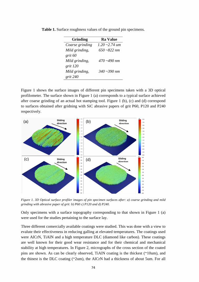
74
Table 1. Surface roughness values of the ground pin specimens.
Figure 1 shows the surface images of different pin specimens taken with a 3D optical profilometer. The surface shown in Figure 1 (a) corresponds to a typical surface achieved after coarse grinding of an actual hot stamping tool. Figure 1 (b), (c) and (d) correspond to surfaces obtained after gridning with SiC abrasive papers of grit P60, P120 and P240 respectively.
Figure 1. 3D Optical surface profiler images of pin specimen surfaces after: a) coarse grinding and mild grinding with abrasive paper of grit: b) P60 c) P120 and d) P240.
Only specimens with a surface topography corresponding to that shown in Figure 1 (a) were used for the studies pertaining to the surface lay.
Three different comercially available coatings were studied. This was done with a view to evalute their effectiveness in reducing galling at elevated temperatures. The coatings used were AlCrN, TiAlN and a high temperature DLC (diamond like carbon). These coatings are well known for their good wear resistance and for their chemical and mechanical stability at high temperatures. In Figure 2, micrographs of the cross section of the coated pins are shown. As can be clearly observed, TiAlN coating is the thickest (~10um), and the thinest is the DLC coating (~2um), the AlCrN had a thickness of about 5um. For all
Grinding Ra Value Coarse grinding 1.20 ~2.74 um Mild grinding, grit 60
650 ~822 nm
Mild grinding, grit 120
470 ~490 nm
Mild grinding, grit 240
340 ~390 nm
(a) (b)
(c) (d)
Sliding direction
Sliding direction
Sliding direction
Sliding direction

75
the coatings, the microstructure of the substrate consists of a compound layer formed during nitriding (prior to PVD deposition).
Figure 2. SEM images of the cross section of the a) AlCrN, b) TiAlN and c) DLC coatings
The properties of the evaluated coatings are listed in Table 2. The hardness values as well as operating temperatures are those provided by the supplier, the surface values were determined in the laboratory by means of 3D optical profilometer.
Table 2. Properties of the coatings used for the tribological tests.
Before surface modification, the tool steels were polished to a surface roughness (Ra) of ~50 nm. In Figure 3, 3D optical surface profiler images of the uncoated polished pin and the as deposited coated pin specimens are shown.
Figure 3. 3D Optical surface profiler images of pin specimen surfaces: a) polished prior to surface modification, b) as delivered AlCrN, c) as delivered TiAlN and d) as delivered DLC
Coating Hardness (HV)
Operating Temp. (ºC)
Ra value (nm)
Coating thickness (um)
AlCrN 3200 1100ºC ~160 ~5 TiAlN 3400 900ºC ~230 ~10 DLC 2000 350ºC ~180 ~2
(a) (b)
(c) (d)
(a) (b) (c)

76
2.2 Test equipment and procedure
The tribological tests were carried out by using an Optimol SRV high-temperature reciprocating friction and wear tester, a more detailed description of the tribometer can be found in [8]. Before the tests all specimens were cleaned with ethanol. The upper pin specimen was kept separated from the lower disc during heating and the holding time. The lower specimen was then heated. This was done with a view to closely simulate the actual process, in which the work-piece is first heated up and then it comes into contact with the cooler tool. Once the desired temperature was reached (900ºC), the lower (work-piece) specimen was retained at that temperature for 4 minutes to allow sufficient time for the diffusion of the Al-Si coating while still separated from the upper (tool) specimen. When a time of 4 minutes had elapsed, the pin was loaded against the disc and the test was started. On completion of the test, the specimens were left to cool in air and then removed and analysed.
The holding time was determined in the laboratory through trial tests. This was done in order to simulate the evolution of the coating in the actual processes.
For the study concerning the influence of surface roughness, the tribological tests were carried out sliding perpendicular to the grinding marks. The experiments to study the impact of the surface lay were done when sliding in a direction parallel and perpendicular to the grinding marks.
The test conditions used for the tests carried out in this work are presented in Table 3.
Table 3. Test parameters
3. Results and discussion
In this section the results from the tribological tests are presented.
3.1 Influence of surface roughness
Figure 4 shows a comparison of the four different ground surfcaes after the tribological tests. The dark zones correspond to the transferred material from the Al-Si coating. As can be observed, the coarse ground specimen shows severe material transfer and most of the pin surface was covered by transferred material. In case of the mild ground specimens, it is clear that regardless of the grit size very little galling occurs.
Test parameters Value Normal Load 31 N Nominal contact pressures 10 MPa Temperature 900ºC Stroke length 4 mm Frequency 12.5 Hz Duration 30 s

77
A mechanism for the occurrence of galling was proposed by the authors in [8]. It was suggested that the occurrence of severe galling occurs by entrapment and compaction of the wear debris. When this is not possible, the severity of galling is mild and through adhesion of the Al-Si coating. The results obtained from the mild ground specimens (Figure 4 (b)- (d)) resemble the results obtained from a milled or polished specimen shown in [8].
Figure 4. SEM images of the upper specimens (tool steel) after the tribological tests: a) coarse ground, b) mild ground grit P60, c) mild ground grit P120 and d) mild ground grit P240. Contact pressure: 10 MPa; Sliding direction: left to right.
The results obtained can be explained by taking into account the surface characteristics of the tool steel pin specimens. Figure 5 shows surface profiles of the coarse ground (Figure 5(a)) and the mild ground with grit size P60 (Figure 5(b)) pin specimens prior to the tribological tests. As can be clearly seen, in case of the coarse ground specimen, there are more sites where debris can be accumulated. Wear of the asperities of both surfaces occur during sliding, this results in flattening of the surfaces and generation of wear debris. In case of the mild ground specimens, the asperities are worn fast as they are small and relatively less wear debris are generated. These effects, combined with the fact that the sites where debris can accumulate are few, results in less material transfer.
(a) (b)
(c) (d)

78
Figure 5. Comparison of the as delievered surface profiles of the specimens ground by a) coarse ground and b) mild ground.
3.2 Influence of surface lay orientation
Figure 6 shows the results from the tests involving different orientation of surface roughness marks (lay).. The specimens used for these experiments were coarse ground and correspond to a surface typically encountered after refurbishing of hot stamping tools.
The micrographs show a considerable difference between the two specimens despite having the same surface roughness value (~2 µm). Severe material transfer is observed on the one that slid perpendicular to the surface lay (Figure 6 (a)). On the specimen that slid parallel to the surface lay mild galling occurred at the centre of the the specimen (Figure 6 (b)). The coverage by dark zones (transferred material) is almost negligible. However, at the edge of the specimen wear debris were accumulated outside the area of contact (Figure 6 (c)).
Figure 6. SEM images of the upper specimens (tool steel) after the tribological tests: a) perpendicular sliding to the surface lay orientation, b) parallel sliding to the surface lay orientation (middle) and c) parallel sliding to the surface lay orientation (edge). Contact pressure: 10 MPa; Sliding direction: left to right.
(a) (b) (c)
(a)
(b)

79
The different behaviour of the two surfaces lay orientations can be explained in terms of the entrapment of debris. It is clear that severe material transfer does not occur when the sliding is parallel to the surface lay orientation. Under these conditions it is very likely that the reciprocating sliding allows the loose debris to escape the contact through the valleys of the surface, in a channel-like effect. On the contrary, during sliding in a direction perpendicular to the surface lay pattern, the severity of wear and the entrapment of wear debris give rise to buid-up of material and increased tendency of galling.
3.3 Influence of PVD coatings on the occurrence of galling
Three different PVD coatings were deposited on the surface of polished and nitrided tool steel specimens. The results obtained from the tribological tests using these coated specimens are shown in Figure 7. As can be observed, no significant reduction in galling can be seen for the three coatings. Instead, all coatings showed severe material transfer. In the case of the AlCrN and TiAlN coatings (Figures 7 (a) and 7 (b)), big lumps of transferred material have been formed and the occurrence of severe adhesion can be seen. In case of the DLC coating, the severity of material transfer and adhesion is relatively lower that AlCrN and TiAlN coatings. However, a considerable amount of adhered material and detachment of the coating can be seen.
Energy dispersive spectroscopy (EDS) analysis in regions where the lumps of material transfer and occurrence of adhesive wear were observed showed the presence of silicon. It confirms the transfer of material from the coated UHSS to these regions during sliding.
It should be noted that full coverage of transferred material on the surface of the pin was not observed. The sites where galling is observed seem to be random and there are zones where the coating remains unaffected.
Figure 7. SEM images of the upper specimens(tool steel) after the tribological tests from a) AlCrN coating, b) TiAlN coating and c) DLC coating. Contact pressure: 10 MPa; Sliding direction: left to right
(a) (b) (c)

80
Not only the severity of the material transfer is more significant for the coated specimens, compared to a polished uncoated specimen, but the mechanism of the occurrence of severe galling is also different. For all of these coatings, adhesion seems to be the main initiation mechanism for the occurrence of severe galling and not compaction of debris. As shown in Figure 8, a thicker adhered layer of transferred material is observed. In case of the AlCrN and TiAlN coatings, the lumps that develop are formed through compaction of the debris, however, it appears that severe adhesion occurs first in this case, and this adhered layer acts as an obstacle where debris get accumulated and are compacted.
Figure 8. SEM images of the transferred material showing adhesion as the main mechanism for material transfer: a) AlCrN, b) TiAlN and c) DLC coatings
A possible explanation for the increased severity of adhesion could be an increased affinity between the Al-Si coating from the work-piece and the PVD coatings on the tool steel, in particular with the AlCrN and TiAlN coatings. In a study done by J. Kondratiuk and P. Kuhn [10], it was also shown that severe galling occurs when coatings are used. They suggested that owing to the low melting point of the aluminium, its reactivity and affinity to the tool surface increase. Another aspect to consider is that the surface roughness of the tool steel specimens increased after nitriding and application of the PVD coatings. It has to be kept in mind that the effect of the irregularities of the surface will be amplified when hard coatings are used. Figure 9 shows an image of the coated specimens in the as delivered condition. It is clear from the image that the three coatings have surface irregularities that could be the cause of the increased material transfer. In a study done by B. Podgornik and S. Hogmark [5], they state that polishing of the surface after nitriding can improve the galling resistance of the coatings.
Figure 9. SEM images of the as delivered surface of: a) AlCrN, b) TiAlN and c) DLC coatings
(a) (b) (c)
(a) (b) (c)

81
4. Conclusions
Different ways to alleviate galling at elevated temperatures were explored in this study. The surface roughness level and orientation (lay) of the tool steel as well as PVD coatings deposited on the tool steel were evaluated in terms of their effectiveness in reducing galling. The main conclusions based on this study are as follows:
- The surface roughness (level) obtained by grinding the tool steel specimens using different grit size of SiC abrasive papers, does not have a significant influence on the occurrence of galling.
- The orientation of surface roughness marks (lay) with respect to the sliding direction does influence the galling tendency significantly. Parallel sliding with respect to the surface lay tends to reduce material transfer and the galling tendency
- All the PVD coatings studied in this work and in particular AlCrN and TiAlN coatings have shown high galling tendency
- Even though the DLC coating has shown lower galling tendency compared to that of AlCrN and TiAlN coatings, it is relatively more severe compared to that of uncoated tool steel specimens ground by different SiC abrasive papers.
Acknowledgements
This work has been carried out with financial support from the Centre for High-performance Steel CHS and Gestamp HardTech AB and the authors gratefully acknowledge their support.
References.
[1] Suehiro M., Kusumi K., Maki J., Ohgami M. and Miyakoshi T. Properties of aluminium coated steels for hot forming. Nippon steel technical report No. 88, July 2003.
[2] Hardell J., Pelcastre L. and Prakash B. High-temperature friction and wear characteristics of hardened ultra-high-strength boron steel. Proc. IMechE Part J: J. Engineering Tribology. 2010 (224) 1139-1151
[3] Schedin E. Galling mechanisms in sheet forming operations. Wear 179 (1994) 123-128
[4] Hou Y., Yu Z and Li S. Galling failure analysis in sheet metal forming process. J. Shanghai Jiaotong Univ. (Sci), 15 (2010) 245-249
[5] Podgornik B. and Hogmark S. Surface modification to improve friction and galling properties of forming tools. Journal of Materials Processing Technology 174 (2006) 334-341

82
[6] Sato T., Besshi T., Tsutsui I. and Morimoto T. Anti-galling property of a diamond-like carbon coated tool in aluminium sheet forming. Journal of Materials Processing Technology 104 (2000) 21-24
[7] Eriksson J. and Olsson M. Tribological testing of commercial CrN, (Ti, Al) N and CrC/C PVD coatings- Evaluation of galling and wear characteristics against different high strength steels. Surface & Coatings Technology 205 (2011) 4045-4051
[8] Pelcastre L., Hardell J. and Prakash B. Investigations into the occurrence of galling during hot forming of Al-SI high strength steel. Proc. IMech Part J: J. Engineering tribology. 2011 (225) 487-498
[9] Yanagida A. and Azushima A. Evaluation of coefficients of friction in hot stamping by hot flat drawing test. CIRP Annals- Manufacturing Technology 58 (2009) 247-250
[10] Kondratiuk J. and Kuhn P. Tribological investigation on friction and wear behaviour of coatings for hot sheet metal forming. Wear 270 (2011) 839-849.

