hot melt application head series pw -...
TRANSCRIPT

Hot Melt Application HeadSeries PW...
Manual P/N 458013I– English –
NORDSON ENGINEERING GMBH � LÜNEBURG � GERMANY

� 2004 Nordson CorporationAll rights reserved
PWIssued 06/04
COV_EN_458013I
NoteThis manual applies to the entire series.
Order numberP/N = Order number for Nordson products
NoticeThis is a Nordson Corporation publication which is protected by copyright. Original copyright date 1999.
No part of this document may be photocopied, reproduced, or translated to another language without the priorwritten consent of Nordson Corporation. The information contained in this publication is subject to change without
notice.
TrademarksAccuJet, AquaGuard, Asymtek, Automove, Autotech, Blue Box, CF, CanWorks, Century, Clean Coat, CleanSleeve, CleanSpray, Compumelt, Control Coat,Cross-Cut, Cyclo-Kinetic, Dispensejet, DispenseMate, Durafiber, Durasystem, Easy Coat, Easymove Plus, Econo-Coat, EPREG, ETI, Excel 2000, Flex-O-Coat,FlexiCoat, Flexi-Spray, Flow Sentry, Fluidmove, FoamMelt, FoamMix, Helix, Horizon, Hose Mole, Hot Shot, Hot Stitch, Isocoil, Isocore, Iso-Flo, JR, KB30, Little Squirt,Magnastatic, MEG, Meltex, MicroSet, Millenium, Mini Squirt, Moist-Cure, Mountaingate, MultiScan, Nordson, OmniScan, Opticoat, OptiMix, Package of Values,Patternview, PluraFoam, Porous Coat, PowderGrid, Powderware, Prism, Pro-Flo, ProLink, Pro-Meter, Pro-Stream, PRX, RBX, Rhino, S. design stylized, Saturn,SC5, Seal Sentry, Select Charge, Select Coat, Select Cure, Slautterback, Smart-Coat, Spray Squirt, Spraymelt, Super Squirt, Sure Coat, System Sentry, Tela-Therm,Trends, Tribomatic, UniScan, UpTime, Veritec, Versa-Coat, Versa-Screen, Versa-Spray, Walcom, Watermark, When you expect more. are registered trademarks– � – of Nordson Corporation.
ATS, Aerocharge, Auto-Flo, AutoScan, BetterBook, Chameleon, CanNeck, Check Mate, Colormax, Control Weave, Controlled Fiberization, Coolwave, CPX, Dry Cure,E-Nordson, EasyClean, Eclipse, Equi=Bead, Fill Sentry, Fillmaster, Gluie, Heli-Flow, Ink-Dot, Iso-Flex, Kinetix, Lacquer Cure, Maxima, MicroFin, Minimeter, Multifil,Origin, PermaFlo, PluraMix, Powder Pilot, Powercure, Primarc, Process Sentry, PurTech, Pulse Spray, Ready Coat, Select Series, Sensomatic, Shaftshield,SheetAire, Spectral, Spectronic, Spectrum, Summit, Sure Brand, Sure Clean, Sure Max, Swirl Coat, Tempus, Tracking Plus, Trade Plus, Universal, Vista, Web Cure,2 Rings (Design) are trademarks – � – of Nordson Corporation.
Designations and trademarks stated in this document may be brands that, when used by third parties for their own purposes, could lead to violation of the owners’ rights.

Table of Contents I
� 2004 Nordson CorporationAll rights reserved
PWIssued 06/04
P/N 458013I
Table of Contents
1. . . . . . . . . . . . . . . . . . . . . . . . . . . . . . . . . . . . . . . . . . . . . . . . . . . . . . . . . . . . . . .
1. Intended Use 1. . . . . . . . . . . . . . . . . . . . . . . . . . . . . . . . . . . . . . . . . . . . . . .
Unintended Use – Examples – 1. . . . . . . . . . . . . . . . . . . . . . . . . . . . . .
2. Residual Risks 2. . . . . . . . . . . . . . . . . . . . . . . . . . . . . . . . . . . . . . . . . . . . . .
3. Note on Manual 2. . . . . . . . . . . . . . . . . . . . . . . . . . . . . . . . . . . . . . . . . . . . .
4. Functioning 2. . . . . . . . . . . . . . . . . . . . . . . . . . . . . . . . . . . . . . . . . . . . . . . . .
Principle Drawing Adhesive Flow 3. . . . . . . . . . . . . . . . . . . . . . . . . . .
5. ID Plate 3. . . . . . . . . . . . . . . . . . . . . . . . . . . . . . . . . . . . . . . . . . . . . . . . . . . .
6. Illustrations 4. . . . . . . . . . . . . . . . . . . . . . . . . . . . . . . . . . . . . . . . . . . . . . . . .
Model with Swivel Device 4. . . . . . . . . . . . . . . . . . . . . . . . . . . . . . . . . .
Model with Linear Unit 5. . . . . . . . . . . . . . . . . . . . . . . . . . . . . . . . . . . . .
1. Unpacking 6. . . . . . . . . . . . . . . . . . . . . . . . . . . . . . . . . . . . . . . . . . . . . . . . . .
2. Transport 6. . . . . . . . . . . . . . . . . . . . . . . . . . . . . . . . . . . . . . . . . . . . . . . . . .
3. Installation 6. . . . . . . . . . . . . . . . . . . . . . . . . . . . . . . . . . . . . . . . . . . . . . . . .
Exhausting Adhesive Vapors 6. . . . . . . . . . . . . . . . . . . . . . . . . . . . . . .
4. Storage 6. . . . . . . . . . . . . . . . . . . . . . . . . . . . . . . . . . . . . . . . . . . . . . . . . . . .
5. Disposal 6. . . . . . . . . . . . . . . . . . . . . . . . . . . . . . . . . . . . . . . . . . . . . . . . . . .
6. Electrical Connection 7. . . . . . . . . . . . . . . . . . . . . . . . . . . . . . . . . . . . . . . .
Laying Cable 7. . . . . . . . . . . . . . . . . . . . . . . . . . . . . . . . . . . . . . . . . . . . .
Connecting Application Head 7. . . . . . . . . . . . . . . . . . . . . . . . . . . . . . .
Solenoid Valves with Separate Connecting Cable 7. . . . . . . . . . .
7. Pneumatic Connection 8. . . . . . . . . . . . . . . . . . . . . . . . . . . . . . . . . . . . . . .
Operating with Non-lubricated Control Air 8. . . . . . . . . . . . . . . . . . . .
Operating with Lubricated Compressed Air 8. . . . . . . . . . . . . . . . . . .
Connecting Control Air 9. . . . . . . . . . . . . . . . . . . . . . . . . . . . . . . . . . . . .
Control Modules 9. . . . . . . . . . . . . . . . . . . . . . . . . . . . . . . . . . . . . . . .
Swivel Device / Linear Unit 9. . . . . . . . . . . . . . . . . . . . . . . . . . . . . .
Safety
Description
Installation

Table of ContentsII
� 2004 Nordson CorporationAll rights reserved
PWIssued 06/04
P/N 458013I
8. Installing Heated Hoses 10. . . . . . . . . . . . . . . . . . . . . . . . . . . . . . . . . . . . .
Connecting 10. . . . . . . . . . . . . . . . . . . . . . . . . . . . . . . . . . . . . . . . . . . . . .
Disconnecting 10. . . . . . . . . . . . . . . . . . . . . . . . . . . . . . . . . . . . . . . . . . .
Relieving Pressure 10. . . . . . . . . . . . . . . . . . . . . . . . . . . . . . . . . . . .
Second Open-jawed Wrench 10. . . . . . . . . . . . . . . . . . . . . . . . . . . .
1. Triggering Solenoid Valve 11. . . . . . . . . . . . . . . . . . . . . . . . . . . . . . . . . . .
2. Setting Temperatures 11. . . . . . . . . . . . . . . . . . . . . . . . . . . . . . . . . . . . . . .
3. Important When Using Polyurethane Application Materials (PUR) 11. . . . . . . . . . . . . . . . . . . . .
4. Setting Adhesive Application Quantity 12. . . . . . . . . . . . . . . . . . . . . . . . .
Setting Nozzle Stem Stroke 12. . . . . . . . . . . . . . . . . . . . . . . . . . . . . . .
5. Positioning Application Head 13. . . . . . . . . . . . . . . . . . . . . . . . . . . . . . . .
Setting Depth of Submersion 13. . . . . . . . . . . . . . . . . . . . . . . . . . . . . .
Setting Application Width and Position 13. . . . . . . . . . . . . . . . . . . . . .
6. Settings Record Form 14. . . . . . . . . . . . . . . . . . . . . . . . . . . . . . . . . . . . . .
1. Relieving Pressure 15. . . . . . . . . . . . . . . . . . . . . . . . . . . . . . . . . . . . . . . . .
2. Maintenance Table 16. . . . . . . . . . . . . . . . . . . . . . . . . . . . . . . . . . . . . . . . .
3. Visual Inspection for External Damage 16. . . . . . . . . . . . . . . . . . . . . . . .
4. Lubricating Spindles 16. . . . . . . . . . . . . . . . . . . . . . . . . . . . . . . . . . . . . . . .
5. External Cleaning 17. . . . . . . . . . . . . . . . . . . . . . . . . . . . . . . . . . . . . . . . . .
6. Replacing Control Module 17. . . . . . . . . . . . . . . . . . . . . . . . . . . . . . . . . . .
7. Removing Nozzle Insert 18. . . . . . . . . . . . . . . . . . . . . . . . . . . . . . . . . . . . .
8. Purging with Cleaning Agent 19. . . . . . . . . . . . . . . . . . . . . . . . . . . . . . . . .
9. Replacing Seals 20. . . . . . . . . . . . . . . . . . . . . . . . . . . . . . . . . . . . . . . . . . . .
Plug Plate 20. . . . . . . . . . . . . . . . . . . . . . . . . . . . . . . . . . . . . . . . . . . . . . .
Plug Plate with Seal Design C 20. . . . . . . . . . . . . . . . . . . . . . . . . . .
Plug Plates with Older Seal Designs 21. . . . . . . . . . . . . . . . . . . . .
Piston 22. . . . . . . . . . . . . . . . . . . . . . . . . . . . . . . . . . . . . . . . . . . . . . . . . .
Piston with Seal Design B 22. . . . . . . . . . . . . . . . . . . . . . . . . . . . . .
Piston with Seal Design A 23. . . . . . . . . . . . . . . . . . . . . . . . . . . . . .
10. Internal cleaning 24. . . . . . . . . . . . . . . . . . . . . . . . . . . . . . . . . . . . . . . . . . .
Disassembling Mouthpiece 25. . . . . . . . . . . . . . . . . . . . . . . . . . . . . . . .
Assembling Mouthpiece 25. . . . . . . . . . . . . . . . . . . . . . . . . . . . . . . . . .
11. Maintenance Record Form 26. . . . . . . . . . . . . . . . . . . . . . . . . . . . . . . . . .
Installation (contd.)
Operation
Maintenance

Table of Contents III
� 2004 Nordson CorporationAll rights reserved
PWIssued 06/04
P/N 458013I
1. Troubleshooting Table 27. . . . . . . . . . . . . . . . . . . . . . . . . . . . . . . . . . . . . .
1. Operating Specifications 29. . . . . . . . . . . . . . . . . . . . . . . . . . . . . . . . . . . .
2. Electrical Specifications 29. . . . . . . . . . . . . . . . . . . . . . . . . . . . . . . . . . . . .
3. Other Specifications 29. . . . . . . . . . . . . . . . . . . . . . . . . . . . . . . . . . . . . . . .
30. . . . . . . . . . . . . . . . . . . . . . . . . . . . . . . . . . . . . . . . . . . . . . . . . . . . . . . . . . . . . .
Troubleshooting
Specifications
Processing Materials

Table of ContentsIV
� 2004 Nordson CorporationAll rights reserved
PWIssued 06/04
P/N 458013I

Hot Melt Application Head Series PW ... 1
� 2004 Nordson CorporationAll rights reserved
PWIssued 06/04
P/N 458013I
Safety
WARNING: Observe and follow all safety instructions, thegeneral safety instructions included as a separate document, aswell as the specific safety instructions in all other relateddocumentation.
Description
Hot melt application heads of the series PW ... – hereafter also referredto as application head – may be used only to apply polyolefine, EVA andPUR hot melt adhesives.
Any other use is considered to be unintended. Nordson will not be liablefor personal injury or property damage resulting from unintended use.
Intended use includes the observance of Nordson safety instructions.Nordson recommends obtaining detailed information on the materials tobe used.
The application heads may not be used under the following conditions:
� In defective condition
� When changes or modifications have been made by the customer
� In a potentially explosive atmosphere
� With unsuitable adhesives
� When the values stated under Specifications are not complied with.
The application heads may not be used to process the followingmaterials:
� Explosive and flammable materials
� Erosive and corrosive materials
� Food products.
1. Intended Use
Unintended Use – Examples –

Hot Melt Application Head Series PW ...2
� 2004 Nordson CorporationAll rights reserved
PWIssued 06/04
P/N 458013I
In the design of the unit, every measure was taken to protect personnelfrom potential danger. However, some residual risks can not be avoided.Personnel should be aware of the following:
� Risk of burns on the hot application head: from hot adhesive, whenreplacing filter cartridge and when making adjustments.
� Inhalation of potentially hazardous hot melt adhesive vapors.
The position numbers in the illustrations do not correspond to the positionnumbers in the technical drawings and the parts lists.
The illustrations show only the essential components. All othercomponents and details can be found in the included technical drawings(Refer to Parts List ).
The application heads PW... are intended to coat foils that are thenadhered to profiles of varying shapes and materials (Profile Wrapping).Polyolefine, EVA and PUR hot melt adhesives can be processed.
The application width can be steplessly adjusted between 5 mm and themaximum application width during operation.
NOTE: The number in the type designation indicates the maximumapplication width in mm.
NOTE: Some models have a set minimum application width. Refer toseparate technical drawing for application pattern.
A swivel device or linear unit (PW 1000 and higher) with web guide forguiding the substrate is integrated. When work is interrupted for longerperiods of time, the application slit (nozzle) can be closed almost all theway with the application width adjuster (not on models with minimumapplication width). This also causes almost all of the adhesive residuethat would otherwise harden in the application head to be pressed out ofthe application head. The nonstick coating on the parts coming intocontact with adhesive makes external cleaning easier.
Electrical heater cartridges are used to heat the unit. The temperature iscontinuously measured by a temperature sensor and controlled by anelectronic temperature controller located in the electrical cabinet of afeeding unit or in a separate electrical cabinet.
2. Residual Risks
3. Note on Manual
4. Functioning

R
Nordson Engineering GmbH
WV
D 21337 Lüneburg – Germany
CFSY084S0501095
Hot Melt Application Head Series PW ... 3
� 2004 Nordson CorporationAll rights reserved
PWIssued 06/04
P/N 458013I
002884
5
1 32
4
Control air
Hot melt adhesive
Fig. 1
1 Control rod2 Filter cartridge
3 Hose connection4 Clamping device
5 Piston rod
Type of application head
Nordson order number
Serial number
Operating voltage V = Volt
Power consumption W = Watt
Fig. 2
Principle Drawing AdhesiveFlow
5. ID Plate

Hot Melt Application Head Series PW ...4
� 2004 Nordson CorporationAll rights reserved
PWIssued 06/04
P/N 458013I
Because the unit is continuously being modified and improved, there areseveral models in the series PW .... Thus illustrations in this manual candeviate from the actual unit. When appropriate, consult the includedTechnical Drawing.
Figure 3 shows the essential components of the application head using aPW 350 as an example. More detailed illustrations can be found in theenclosed technical drawings.
002963
1 2 4
9 7 6 5
3
8
13 1410 1211
Fig. 3 Application head PW 350 with swivel device and web guide
1 Control rod2 Clamping device3 Handwheel Piston adjustment4 Handwheel Position adjustment5 Pneumatic cylinder with stop
6 Piston rod7 Mouthpiece with application slit
(nozzle)8 Reservoir9 Swivel device
10 Filter cartridge*11 Hose connection12 Connections Heater13 Solenoid valve Control modules14 Solenoid valve Swivel device
Note: There are separate manuals available for components marked with an asterisk (*).Note: The handwheels Piston adjustment and Position adjustment can also be attached to the other side of the application
head. On models with only one hose connection, the connection is always on the piston side of the application head.
6. Illustrations
Model with Swivel Device

Hot Melt Application Head Series PW ... 5
� 2004 Nordson CorporationAll rights reserved
PWIssued 06/04
P/N 458013I
Figure 4 shows the essential components of an application head using aPW 1300 as an example. More detailed illustrations can be found in theenclosed technical drawings.
002787
PW 1300
4
1 2 3
5689 7
10
11
12
13
4
Fig. 4 Example: Application head PW 1300 with linear unit and web guide
1 Assembly Application head2 Edge band guide3 Linear unit
4 Handwheels Piston adjustment5 Clamping device6 Limit stop7 Control rod8 Piston rod9 Anti-twist device
10 Filter cartridges *11 Hose connections12 Connections Heater13 Reservoirs
Note: There are separate manuals available for components marked with an asterisk (*).
Model with Linear Unit

Hot Melt Application Head Series PW ...6
� 2004 Nordson CorporationAll rights reserved
PWIssued 06/04
P/N 458013I
Installation
WARNING: Allow only qualified personnel to perform thefollowing tasks. Observe and follow the safety instructions inthis document and all other related documentation.
Unpack carefully. Then check for any damage caused during shipping.Reuse packaging materials or dispose of properly according to localregulations.
NOTE: The application head is a high precision, valuable part. Handlevery carefully! Protect the mouthpiece from damage.
Install the application head in the appropriate place in the coatingmachine. Observe the following:
� Do not operate in a potentially explosive atmosphere
� Protect from humidity, vibrations, dust and drafts
� Ensure access to parts relevant for maintenance and operation
� Position correctly: Control modules must be on top
� Protect mouthpiece from damage.
Ensure that adhesive vapors do not exceed the prescribed limits.Exhaust adhesive vapors when necessary. Provide sufficient ventilationof the location where the unit is installed.
Do not store outside! Protect from humidity and dust. Do not lay unit onthe mouthpiece. Protect the mouthpiece from damage.
When your Nordson product has exhausted its purpose and/or is nolonger needed, dispose of it properly according to local regulations.
1. Unpacking
2. Transport
3. Installation
Exhausting Adhesive Vapors
4. Storage
5. Disposal

Hot Melt Application Head Series PW ... 7
� 2004 Nordson CorporationAll rights reserved
PWIssued 06/04
P/N 458013I
WARNING: Risk of electrical shock. Failure to observe mayresult in personal injury, death, or equipment damage.
WARNING: Ensure that cables do not touch rotating and/or hotunit components. Do not pinch cables and check regularly fordamage. Replace damaged cables immediately!
WARNING: Only operate with the voltage shown on the IDplate.
Link the heater connections to the corresponding outlets of thehigher-ranking system components (electrical cabinet of a feeding unit orseparate electrical cabinet), depending on system and quantity of heatedhose:
� Via the sockets/connecting lines for heated hoses
� Via separate connecting cables.
Use safety clips – when available – to secure the plug connection.
Solenoid Valves with Separate Connecting Cable
With application heads PW ..., the solenoid valves are usually triggeredvia separate cable, not via sockets / connecting lines for heated hoses.
WARNING: Operate solenoid valves only with the voltageshown on the ID plate.
CAUTION: Trigger control module solenoid valve(s) only whenthe application head is heated to operating temperature! If theadhesive is too cold, control module seals may be damaged.
6. Electrical Connection
Laying Cable
Connecting Application Head

Hot Melt Application Head Series PW ...8
� 2004 Nordson CorporationAll rights reserved
PWIssued 06/04
P/N 458013I
The application head may only be connected to pressure-controlled andconditioned compressed air.
The quality of the compressed air must be at least class 2 as stipulatedby ISO 8573–1. This means:
� Max. particle size 1 �m
� Max. particle density 1 mg/m3
� Max. pressure dewpoint –40 �C / –40 �F
� Max. oil concentration 0.1mg/m3.
When control modules / application heads are connected to acompressed air system in which the compressed air has previously beenlubricated, simply ceasing to lubricate the air is not sufficient. The oilremaining in the compressed air supply will reach the solenoid valvesand the control modules and wash out the lubricant/oil from these parts,substantially decreasing the lifetime of the units.
To operate with non-lubricated control air, ensure that
� The system has been converted to absolutely non-lubricatedoperation
� No oil from a possible defective compressor can penetrate thecompressed air supply.
NOTE: Nordson will assume no warranty/liability for damage resultingfrom unpermitted, temporary lubrication.
The application heads / control modules can also be operated withlubricated compressed air.
NOTE: Once the air has been lubricated, it must always be lubricated;the lubricated compressed air will wash out the lubricant on the solenoidvalves and the control modules. Nordson recommends:
Oil P/N
Klüber Unisilkon TK002/50 316 578
7. Pneumatic Connection
Operating with Non-lubricatedControl Air
Operating with LubricatedCompressed Air

Hot Melt Application Head Series PW ... 9
� 2004 Nordson CorporationAll rights reserved
PWIssued 06/04
P/N 458013I
Control air pressures are adjusted on external compressed air controlvalves. The pressure control valves are not part of the application head.
Control Modules
1. Connect an adjustable air supply to the air connection of the solenoidvalve Control module (13, Fig. 3).
2. Set control air pressure to 4 to 6 bar (0.4 to 0.6 MPa / 58 to 87 psi).The exact pressure must be determined for each application.
Swivel Device / Linear Unit
WARNING: Risk of squash! When EMERGENCY OFF occurs,ensure that the air supply is stopped with the customer’sEMERGENCY OFF chain.
1. Connect an adjustable air supply to the air connection of the solenoidvalve Swivel device (14, Fig. 3) or Linear unit.
2. Set control air pressure to 4 to 6 bar (0.4 to 0.6 MPa / 58 to 87 psi).The exact pressure must be determined for each application.
Connecting Control Air

MXHH001S050B0997
1 32
MXHH002S033A0295
Hot Melt Application Head Series PW ...10
� 2004 Nordson CorporationAll rights reserved
PWIssued 06/04
P/N 458013I
WARNING: Hot! Risk of burns. Wear heat-protective gloves.
If there is cold adhesive in the hose connection fitting (1) and/or hoseconnection (2), these components must be heated until the hot meltmaterial softens.
1. First connect the hose (3) electrically to the unit.
2. Heat application head and hose until the adhesive softens.
3. Screw the hose onto the unit.
Fig. 5
WARNING: System and adhesive pressurized. Relieve systempressure before disconnecting heated hoses. Failure to observecan result in serious burns.
Relieving Pressure
1. Set motor speed(s) of the unit feeding the material to 0 min-1 (rpm);switch off motor(s).
2. Place a reservoir under the application slit of the application head.
3. Activate the solenoid valve electrically or manually. Repeat thisprocedure until no more adhesive flows out.
4. Reuse adhesive or dispose of properly according to local regulations.
Second Open-jawed Wrench
Use a second open-jawed wrench when connecting and disconnectingthe heated hose. This prevents the hose connection fitting from turning.
Fig. 6
8. Installing Heated Hoses
Connecting
Disconnecting

Hot Melt Application Head Series PW ... 11
� 2004 Nordson CorporationAll rights reserved
PWIssued 06/04
P/N 458013I
Operation
WARNING: Allow only qualified personnel to perform thefollowing tasks. Observe and follow the safety instructions inthis document and all other related documentation.
Trigger the solenoid valve Control modules only when the applicationhead is heated to operating temperature! If the adhesive is too cold,control module seals may be damaged.
The procedure for setting the temperatures is described in thetemperature controller manual. Temperature controllers are not part ofthe application head. They can be located e.g. in the electrical cabinet ofthe feeding unit or in a separate electrical cabinet.
NOTE: The temperature setting is determined by the processingtemperature prescribed by the adhesive supplier. The maximumoperating temperature for the product and heated components describedhere may not be exceeded.
CAUTION: The maximum operating temperature (200�C / 392 �F) may not be exceeded.
Nordson will assume no warranty or liability for damage resulting fromincorrect temperature settings.
It is imperative that the following guidelines are followed when processingpolyurethane application materials (PUR):
� Wear respiratory protection when the maximum permissibleconcentration of hazardous substances is exceeded.
� During production interruptions and work breaks, reduce temperatureand close application slit using the handwheels Piston adjustmentand Position adjustment as far as possible. Cover remaining openingwith special grease (Refer to Processing Materials).
� Before prolonged standstill of the application system, purge with asuitable cleaning agent. Use only a cleaning agent recommended bythe material manufacturer.
� Close open material connections.
1. Triggering SolenoidValve
2. Setting Temperatures
3. Important When UsingPolyurethane ApplicationMaterials (PUR)

002868
Max. + 2.8 mmMax. + 1.175in. 1
2
Hot Melt Application Head Series PW ...12
� 2004 Nordson CorporationAll rights reserved
PWIssued 06/04
P/N 458013I
The adhesive application quantity depends on the desired adhesiveapplication weight and on the substrate speed. It is usually preselectedusing the pump speed dials. The optimum setting must be determined bytrial and error.
The speed dials are located e.g. in the electrical cabinet of the adhesivefeeding unit or in a separate electrical cabinet.
Depending on the model of the hot melt adhesive application system,pump speed control can also occur with a tach generator or an electroniccoating weight control.
Some control modules are equipped with a nozzle stem adjustment. It isused for fine adjustment of the adhesive application quantity or theadhesive flow quantity.
As the control module closes, the nozzle stem presses a small amount ofmaterial out of the surface nozzle. When an application requires only asmall quantity of adhesive, a lower stem stroke should be set to keep thematerial quantity as low as possible.
Figure 7 shows the nozzle stem stroke adjustment with adjusting screw(1) and retaining nut (2).
WARNING: Hazard! The stem stroke adjustment knob has noupper setting limit. If compressed air is connected, never turnthe adjusting screw all the way up; it may jump out.
WARNING: The stem stroke may only be adjusted when theapplication head is heated up! Failure to observe may causedamage to seals.
Fig. 7
Nozzle stem stroke Flow quantity
Counterclockwise (+) = increase Increase
Clockwise (–) = decrease Decrease
4. Setting AdhesiveApplication Quantity
Setting Nozzle Stem Stroke

002869
�15�
002139
A
B
A
B
Hot Melt Application Head Series PW ... 13
� 2004 Nordson CorporationAll rights reserved
PWIssued 06/04
P/N 458013I
To keep tensile forces to the web guide rolls at a minimum, the substrateshould be guided at a right angle to the nozzle.
During coating, the nozzle must be submerged several millimeters intothe substrate. This is done by pneumatically swiveling the web guide orby guiding the head on the linear unit to the web guide.
WARNING: Risk of squash! Do not handle application headwhen the web guide is swiveling in and out or the linear unit ismoving. Swiveling is controlled by an external control unit.
The optimum depth depends, among other factors, on the substrate andthe web tension; it must be determined by trial and error.
Fig. 8
CAUTION: Adjust the stops such that the web guide does nottouch the mouthpiece, even when swiveled in.
Set limit stops to achieve the desired insertion depth. Set the proximityswitches on the pneumatic cylinder such that they switch when positionSwiveled in has been reached.
On some models the upper web guide roll can be adjusted parallel byseveral millimeters to optimize the web path.
CAUTION: Adjust application width and position only when theapplication head is heated. Otherwise cold material will damagethe application head.
When the handwheel Piston adjustment is turned, the piston moves inthe nozzle and the application width changes. When the handwheelPosition adjustment is turned, the nozzle moves over the piston and theapplication width also changes. When both handwheels are turned, theposition of the adhesive path on the substrate can be moved. The bestway to determine the direction of rotation of the handwheels is to try themout before initial startup.
Fig. 9 Principle drawing
5. Positioning ApplicationHead
Setting Depth of Submersion
Setting Application Width andPosition

Hot Melt Application Head Series PW ...14
� 2004 Nordson CorporationAll rights reserved
PWIssued 06/04
P/N 458013I
Production information
Adhesive Manufacturer
Softening temperature
Max. processing temperature
Viscosity
Cleaning agent / rinsingmaterial
Manufacturermaterial Max. heating temperature
Flash point
Basic settings Control air pressure
Stem stroke (rotations)
Application width
Temperatures Setpoint
Undertemperature
Overtemperature
Notes
Form filled out by:
Name Date
6. Settings Record Form

Hot Melt Application Head Series PW ... 15
� 2004 Nordson CorporationAll rights reserved
PWIssued 06/04
P/N 458013I
Maintenance
WARNING: Allow only qualified personnel to perform thefollowing tasks. Observe and follow the safety instructions inthis document and all other related documentation.
NOTE: Maintenance is an important preventive measure for maintainingoperating safety and extending the operational lifetime of the unit. Itshould not be neglected under any circumstances.
WARNING: System and adhesive pressurized. Beforedisconnecting heated hoses and replacing filter cartridges,relieve system pressure. Failure to observe can result in seriousburns.
WARNING: Hot! Risk of burns. Wear safety goggles andheat-protective gloves.
1. Set motor speed(s) of feeding unit to 0 min-1 (rpm); switch offmotor(s).
2. Place a reservoir under the application slit of the application head.
3. Activate the solenoid valve electrically or manually. Repeat thisprocedure until no more adhesive flows out.
4. Reuse adhesive or dispose of properly according to local regulations.
1. Relieving Pressure

Hot Melt Application Head Series PW ...16
� 2004 Nordson CorporationAll rights reserved
PWIssued 06/04
P/N 458013I
The maintenance intervals are general guidelines based on experience.Depending on the location of the unit, the production conditions and theoperating time, other maintenance intervals may prove necessary.
Unit part Activity Interval Refer to
Complete applicationsystem
Purge with cleaning agent When changing adhesive, if theadhesives used can not bemixed
Before prolonged productioninterruptions, if PUR adhesive isprocessed
Page 19
Observe adhesivemanufacturer’s
instructions
Complete applicationhead
Visual inspection Daily Page 16
External cleaning Daily Page 17
Mouthpiece External cleaning Daily Page 17
Internal cleaning When dirty Page 24
Seals Replace When damaged Page 20
Control module Check inspection hole* Weekly –
Replace When leaking Page 17
Spindles Lubricate As needed Page 16
Filter cartridge Refer to separate manual
NOTE: * The inspection hole is the hole in the control module casingthrough which the nozzle stem can be seen.
WARNING: When damaged parts pose a risk to theoperational safety of the unit and/or safety of personnel, switchoff the unit and have the damaged parts replaced by qualifiedpersonnel. Use only original Nordson spare parts.
Use only temperature-resistant grease to lubricate the spindles on thepiston and position adjustment. Nordson recommends special hightemperature grease (Refer to Processing Materials).
2. Maintenance Table
3. Visual Inspection forExternal Damage
4. Lubricating Spindles

EPAH305S050A1297
Hot Melt Application Head Series PW ... 17
� 2004 Nordson CorporationAll rights reserved
PWIssued 06/04
P/N 458013I
External cleaning prevents impurities created during production fromcausing the unit to malfunction.
CAUTION: Do not damage or remove warning signs. Damagedor removed warning signs must be replaced by new ones.
CAUTION: Never use hard tools. Use extreme care whenhandling the mouthpiece.
WARNING: Hot! Risk of burns. Wear heat-protective gloves.
Remove adhesive residue only with a cleaning agent recommended bythe adhesive supplier. Heat with an air heater if necessary. Remove dust,flakes etc. with a vacuum cleaner or a soft cloth.
1. Remove hot melt adhesive residue from the mouthpiece promptlywith a soft cloth.
2. Remove tough and hardened residue with a wooden or PTFE spatula if necessary.
WARNING: Hot! Risk of burns. Wear heat-protective gloves.
CAUTION: To prevent damage to seals and nozzle stem,replace control modules only when application head is heated.
1. Heat application head until adhesive is soft.
2. Set to maximum application width.
3. Relieve pressure.
4. Disconnect compressed air hoses.
5. Release fastening screws and replace control module.
6. Screw new control module into place.
7. Reconnect compressed air.Fig. 10 Principle drawing
NOTE: The stem stroke adjustment (when present) usually does notrequire adjustment.
5. External Cleaning
6. Replacing ControlModule

002623
2
1
Hot Melt Application Head Series PW ...18
� 2004 Nordson CorporationAll rights reserved
PWIssued 06/04
P/N 458013I
NOTE: The nozzle insert is the part in which the nozzle stem of thecontrol module blocks or releases the material flow. Older applicationhead models use a body with integrated nozzle receptacle instead.Control module models to be used with a separate nozzle insert can berecognized by the rounded nozzle stem tip.
1. Remove control module (Refer to Replacing Control Module).
2. Extract nozzle insert (2) from control module hole. Do this by insertingincluded tool (1), turning 45� and extracting.
3. Always replace the O-ring on the nozzle insert.
Fig. 11
7. Removing Nozzle Insert

Hot Melt Application Head Series PW ... 19
� 2004 Nordson CorporationAll rights reserved
PWIssued 06/04
P/N 458013I
CAUTION: Use only a cleaning agent recommended by theadhesive manufacturer. Observe Manufacturer Safety DataSheet (MSDS) for the cleaning agent.
WARNING: Hot! Risk of burns. Wear safety goggles andheat-protective gloves.
1. Empty the feeding unit and fill with cleaning agent.
2. Heat up heated system components. Comply with maximum heatingtemperature of cleaning agent.
3. Place a suitable reservoir under the application slit.
4. Set the speed and pressure of the feeding unit to the lowest values.
5. Activate the solenoid valve electrically or manually.
6. Switch on feeding unit.
7. Continue to convey the cleaning agent until the cleaning agentflowing out of the unit no longer contains adhesive residue.
NOTE: Properly dispose of cleaning agent according to local regulations.
NOTE: Before starting production again, flush out cleaning agent residueusing the new hot melt adhesive.
8. Purging with CleaningAgent

Hot Melt Application Head Series PW ...20
� 2004 Nordson CorporationAll rights reserved
PWIssued 06/04
P/N 458013I
The seals must be replaced when adhesive is emitted outside of the setwidth.
WARNING: Risk of squash! Ensure that the swivel device /linear unit can not be triggered. Stop control air supply toprevent triggering.
WARNING: Hot! Risk of burns. Wear heat-protective gloves.
NOTE: When a seal is replaced, the inside of the mouthpiece shouldalways be cleaned (Refer to Internal Cleaning).
NOTE: Only models with only one piston (up to application width 800 mm) have a plug plate.
Plug Plate with Seal Design C
1 2
3
4
5
003046
1
Fig. 12 Plug plate, seal design C (assembly P/N 206215)
1 End plateP/N 206256
2 Sealing socketP/N 206255
3 O-ringP/N 250263
4 Sealing plateP/N 206257
5 Sealing cordP/N 252430
1. Heat application head until adhesive is soft.
NOTE: Hardened reactive adhesives (PUR) can not be softened.
2. Relieve pressure (Refer to Relieving Pressure).
3. Remove end plate (1).
4. Disassemble mouthpiece (Refer to Internal Cleaning, DisassemblingMouthpiece).
9. Replacing Seals
Plug Plate

Hot Melt Application Head Series PW ... 21
� 2004 Nordson CorporationAll rights reserved
PWIssued 06/04
P/N 458013I
5. Detach parts 2 and 5.
6. For best results, the assembly P/N 206215 should be completelyreplaced. Parts 2 and 5 are already built into the assembly.Otherwise:
a. Pry open sealing socket (2) (e.g. with a retaining ring pliers) to beable to extract the sealing plate.
b. Remove old sealing cord.c. Lay new sealing cord in groove and press lightly into place
(smooth vice jaws!).d. Replace O-ring.e. Pry open sealing socket and put plate back into place.f. Insert assembled parts 2 to 5 in mouthpiece.
7. Replace piston seals if necessary (Refer to Piston).
8. Assemble mouthpiece.
9. Screw on end plate.
Plug Plates with Older Seal Designs
Plug plates with older seal designs can be recognized by the graspingthread.
NOTE: For best results, the plug plate should be replaced with theassembly P/N 206215 (plug plate with seal design C) for better sealinginstead of simply replacing the seal.
003047
BA1
3
2
4
5
6
7
Fig. 13 Plug Plates, Seal Designs A and B
1 Grasping thread 2 Plug plate P/N 4553913 Not shown:
Sealing socket P/N 4594294 Not shown:
Sliding seal P/N 455440
5 Plug plate P/N 4642346 Sealing socket P/N 4594297 Flat seal P/N 789731

2 31 4
002958
0029595 6 7 8 9
Hot Melt Application Head Series PW ...22
� 2004 Nordson CorporationAll rights reserved
PWIssued 06/04
P/N 458013I
1. Release clamping screw (3) on clamping device and slide clampingdevice over the nut (2) on the piston spindle.
2. Release stop (1) and slide over the nut (2) on the piston spindle.
3. Unscrew anti-twist device (4).
4. Disassemble mouthpiece (Refer to Internal Cleaning, DisassemblingMouthpiece).
5. Crank piston rod all the way off of the spindle and extract it from thebody.
6. Depending on the piston design, proceed as follows:
Fig. 14
Piston with Seal Design B
1. Release screw (5) and pull piston off of piston rod.
2. Clamp piston in a vice and unscrew cap nut (8).
The sealing socket (6, O/N 464226) and flat seal (9, P/N 789731) cannow be checked and, if necessary, replaced.
Re-assembly is in reverse order.
Fig. 15 Piston with Seal Design B(Assembly P/N 464235)
Piston
002960
5 6 7 8 9 10
11 12 13
14
Hot Melt Application Head Series PW ... 23
� 2004 Nordson CorporationAll rights reserved
PWIssued 06/04
P/N 458013I
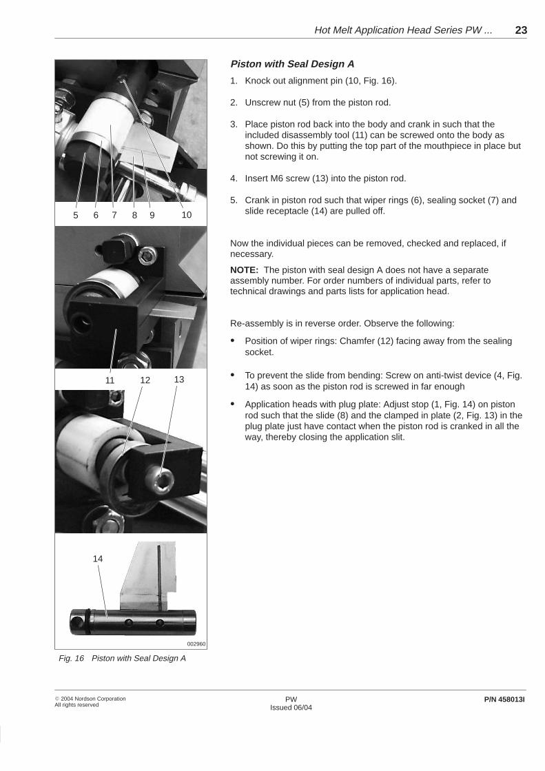
Piston with Seal Design A
1. Knock out alignment pin (10, Fig. 16).
2. Unscrew nut (5) from the piston rod.
3. Place piston rod back into the body and crank in such that theincluded disassembly tool (11) can be screwed onto the body asshown. Do this by putting the top part of the mouthpiece in place butnot screwing it on.
4. Insert M6 screw (13) into the piston rod.
5. Crank in piston rod such that wiper rings (6), sealing socket (7) andslide receptacle (14) are pulled off.
Now the individual pieces can be removed, checked and replaced, ifnecessary.
NOTE: The piston with seal design A does not have a separateassembly number. For order numbers of individual parts, refer totechnical drawings and parts lists for application head.
Re-assembly is in reverse order. Observe the following:
� Position of wiper rings: Chamfer (12) facing away from the sealingsocket.
� To prevent the slide from bending: Screw on anti-twist device (4, Fig.14) as soon as the piston rod is screwed in far enough
� Application heads with plug plate: Adjust stop (1, Fig. 14) on pistonrod such that the slide (8) and the clamped in plate (2, Fig. 13) in theplug plate just have contact when the piston rod is cranked in all theway, thereby closing the application slit.
Fig. 16 Piston with Seal Design A

Hot Melt Application Head Series PW ...24
� 2004 Nordson CorporationAll rights reserved
PWIssued 06/04
P/N 458013I
The inside of the mouthpiece must be cleaned when adhesive residuereduces the quality of the application pattern.
WARNING: Risk of squash! Ensure that the swivel device cannot be triggered. To do this, block the control air supply to theswivel device.
WARNING: Hot! Risk of burns. Wear heat-protective gloves.
CAUTION: Use only a cleaning agent recommended by theadhesive manufacturer. Observe Manufacturer Safety DataSheet (MSDS) for the cleaning agent.
CAUTION: Do not use hard or metallic tools to clean. Do not use wire brushes! This could damage the release coating. Use only soft aids (wooden or PTFE spatula or soft brush).
10. Internal cleaning

1
45
2 3
6002138
Hot Melt Application Head Series PW ... 25
� 2004 Nordson CorporationAll rights reserved
PWIssued 06/04
P/N 458013I
1. Relieve pressure. Refer to Relieving Pressure.
2. Detach plug plate. Refer to Replacing Seals, Plug Plate).
NOTE: With plug plates with seal design C, only the end plate isremoved.
3. Release control rod (2) on clamping device (3) and slide slightly intothe control air strip (1).
4. Remove reservoir (4).
5. Release accessible screws in top section of mouthpiece (6).
6. Screw in included assembly guide pins.
7. Insert M10 screws into the forcing thread of the top section of themouthpiece (6) to separate the top section from the bottom section.
8. Remove adhesive residue from the holes and the channels as well asfrom the sealing surfaces.
Fig. 179. Use a cleaning agent to dissolve adhesive residue that could not be
removed mechanically.
NOTE: Properly dispose of cleaning agent and adhesive residueaccording to local regulations.
1. Put top section of mouthpiece in place; use a rubber hammer ifnecessary.
2. Tighten screws to 60 Nm.
3. Unscrew included assembly guide pins.
Disassembling Mouthpiece
Assembling Mouthpiece

Hot Melt Application Head Series PW ...26
� 2004 Nordson CorporationAll rights reserved
PWIssued 06/04
P/N 458013I
Unit part Activity Date Name Date Name
Application head Purge with cleaning agent
Mouthpiece Disassemble and clean
Control module Check inspection hole
Filter cartridge Clean and replace filterscreenscreen
Spindles Lubricate
11. Maintenance RecordForm

Hot Melt Application Head Series PW ... 27
� 2004 Nordson CorporationAll rights reserved
PWIssued 06/04
P/N 458013I
Troubleshooting
WARNING: Allow only qualified personnel to perform thefollowing tasks. Observe and follow the safety instructions inthis document and all other related documentation.
WARNING: Troubleshooting activities may sometimes have tobe carried out when the unit is energized. Observe all safetyinstructions and regulations concerning energized unitcomponents (active parts). Failure to observe may result in anelectric shock.
When troubleshooting, other components of the application system mayneed to be considered.
The troubleshooting table serves as an aid to qualified personnel. It cannot however replace targeted troubleshooting using e.g the wiringdiagram and measuring instruments. They also do not include allpossible problems, only those which most typically occur.
Problem Possible Cause Corrective Action Refer to
No adhesive Application head has not yetreached operating temperature
Wait until temperature has beenreached, check temperature settingif necessary
Page 11
Not enough adhesive in feeding unit Fill –
Pump of the feeding unit notworking
Check –
Control air not connected Connect Page 9
Mouthpiece blocked Clean inside of mouthpiece,disassemble if necessary
Page 24
Filter cartridge clogged Clean filter cartridge and replacefilter screen
Separatemanual
Nozzle stem is stuck Replace control module Page 17
Continued on next page
1. Troubleshooting Table

Hot Melt Application Head Series PW ...28
� 2004 Nordson CorporationAll rights reserved
PWIssued 06/04
P/N 458013I
Problem Possible Cause Corrective Action Refer to
No adhesive:application headis cold
Temperature not set correctly ontemperature controller
Set correct temperature Page 11
is co ldPlug has no contact Secure plug connection with clip – if
available–
Heater cartridge defective Replace heater cartridge –
Adhesiveapplication is notexact
Mouthpiece partially blocked ordamaged
Clean inside of mouthpiece,disassemble if necessary
Page 24
exactMouthpiece does not have evencontact with the substrate
Check positioning, adjust ifnecessary
Page 13
Production parameters not attunedto one another
Adjust parameters, change ifnecessary
–
Adhesive unsuitable Consult adhesive manufacturer Data sheet
The open time istoo long
Application temperature too high Set temperature lower Page 11too long
Adhesive unsuitable Consult adhesive manufacturer Data sheet
The open time istoo short
Application temperature too low Set temperature higher Page 11too short
Adhesive unsuitable Consult adhesive manufacturer Data sheet
1. Troubleshooting Table(contd.)

Hot Melt Application Head Series PW ... 29
� 2004 Nordson CorporationAll rights reserved
PWIssued 06/04
P/N 458013I
Specifications
Maximum operating temperature 200 �C 392 �F
Operating air pressure
Control modules
Swivel device
4 to 6 bar 0,4 to 0,6 MPa 58 to 87 psi
Maximum adhesive pressure at inlet
When application head is open(triggered)
35 bar 3,5 MPa 507 psi
When application head is closed 50 bar 5 MPa 725 psi
Adhesive viscosity that can beprocessed
5000 mPas to 100000 mPas
Maximum flow quantity (applicationweight) at:
Adhesive pressure = 35 bar / 3.5 MPa /507.5 psi
Adhesive viscosity = 50000 mPas
1000 g/min per 100 mm application width
Note: Ensure that the system component feeding the material (e.g. hotmelt applicator series MC) has sufficient feed capacity to achieve thedesired grammage (adhesive per surface).
Application width 5 to x mm (x depending on type designation)
Note: Some models have a set minimum application width. Refer toseparate technical drawing for application pattern
Heating time Approx. 45 min
Noise emission < 85 dB(A)
Operating voltage (heater) Refer to ID plate
Power consumption Refer to ID plate
Operating voltage (solenoid valve) Refer to ID plates on solenoid valves
Power consumption (solenoid valve) Refer to ID plates on solenoid valves
Possible temperature sensors Fe-CuNi (FE/KO), Ni 120 or Pt 100
Weight PW 350: approx. 90 kg, refer to transport documents for other types
Dimensions Refer to technical drawing
Degree of protection IP 50
1. Operating Specifications
2. Electrical Specifications
3. Other Specifications

Hot Melt Application Head Series PW ...30
� 2004 Nordson CorporationAll rights reserved
PWIssued 06/04
P/N 458013I
Processing Materials
High temperature grease Caution: Do not mix thisl b i t ith th l b i t ! IfTube 250 g P/N 783959 lubricant with other lubricants! Ifnecessary, first clean grease off
Cartridge 400 g P/N 402238necessary, first clean grease offof parts.