hot water -...
TRANSCRIPT
Table Of Contents
Model WBElectric Boilers
Hot Water
Operation and Maintenance Manual
750-13610/2019


Please direct purchase orders for replacement manuals to your local Cleaver-Brooks authorized representative
Manual Part No. 750-136
10/2019 Printed in U.S.A.
Cleaver-Brooks 2019
CLEAVER-BROOKSModel WB
Electric Boilers - Hot Water
Operation and Maintenance Manual
This instruction and maintenance manual presents information that will help to properly operate and care for the equipment. Study its contents carefully. The unit will provide good service and continued operation if proper operating and maintenance instructions are followed.
Cleaver-Brooks boilers are designed and engineered to give long life and excellent service on the job. The electrical and mechanical devices supplied were chosen because of their known ability to perform; however, proper operating techniques and maintenance procedures must be followed at all times. Although these components afford a high degree of protection and safety, due attention should be given to the hazards inher-ent in handling electricity, pressurized hot water, and steam.
It is solely the operator’s responsibility to properly operate and maintain the equipment. No amount of writ-ten instructions can replace intelligent thinking and reasoning and this manual is not intended to relieve the operating personnel of the responsibility for proper operation or the application of timely preventive mainte-nance.
It is recommended that a boiler room log or other permanent record be maintained. Recordings of daily, weekly, monthly, and yearly maintenance activities and recording of may unusual operation will serve as a valuable guide to any necessary investigation.
It is customary to engage the services of a qualified water treatment company or a water consultant to rec-ommend the proper water treating practices. Contact your local Cleaver-Brooks authorized representative for details about water treatment.
The operation of this equipment must comply with all requirements or regulations of the insurance company and/or any other authority having jurisdiction. These legal requirements take precedence over anything con-tained herein.
DO NOT OPERATE, SERVICE, OR REPAIR THIS EQUIPMENT UNLESS YOU FULLY UNDERSTAND ALL APPLICABLE SECTIONS OF THIS MANUAL.
DO NOT ALLOW OTHERS TO OPERATE, SERVICE, OR REPAIR THIS EQUIPMENT UNLESS THEY FULLY UNDERSTAND ALL APPLICABLE SECTIONS OF THIS MANUAL.
FAILURE TO FOLLOW ALL APPLICABLE WARNINGS AND INSTRUCTIONS MAY RESULT IN SEVEREPERSONAL INJURY OR DEATH.
! DANGERWARNING
CONTENTS
CHAPTER 1 General Description 1-11.1 — Introduction 1-1
1.1.1 — Safety Precautions 1-11.1.2 — Abbreviations 1-2
1.2 — Application 1-21.3 — Description 1-21.4 — Principles of Operation 1-4
CHAPTER 2 Installation Instructions 2-12.1 — Receiving Inspection 2-12.2 — Location 2-12.3 — Piping 2-22.4 — Heat Pump Systems with High Flow Rates 2-22.5 — Electrical 2-3
2.5.1 — Electrical Installation Checklist 2-42.5.2 — Recommended Torque Settings 2-5
CHAPTER 3 Pre-Start Preparation 3-13.1 — Inspection 3-13.2 — Boiler and System Cleaning 3-23.3 — Boiler Water Treatment 3-3
CHAPTER 4 Operating Instructions 4-14.1 — Initial Startup 4-14.2 — Maintenance Schedule 4-4
4.2.1 — Weekly Procedure 4-44.2.2 — Quarterly Procedures 4-44.2.3 — Annual Procedure 4-4
4.3 — Element Replacement Procedure 4-54.3.1 — Heating Elements 4-54.3.2 — Element Replacement 4-5
CHAPTER 5 Troubleshooting 5-15.1 — Problems, Causes, and Actions 5-1
CHAPTER 6 Parts 6-16.1 — Ordering Parts 6-1

CHAPTER 1 General Description
1.1 — Introduction
1.1.1 — Safety Precautions
A complete understanding of this manual is required before attempting to operate or maintain the equipment.
It is essential to read and understand all safety precautions before attempting to operate the equipment.
Failure to follow these precautions may result in damage to equipment, serious personal injury, or death.
The equipment should be operated and maintained only by personnel who have read this manual and who have a working knowledge and understanding of the equipment.
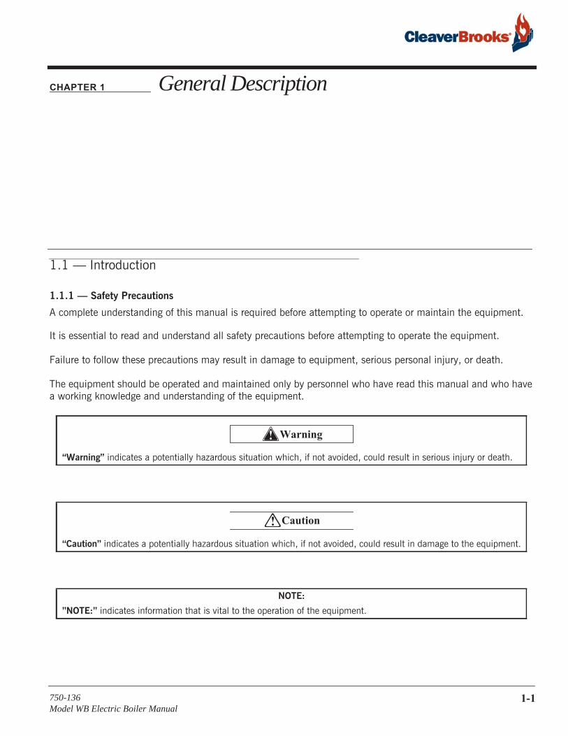
“Warning” indicates a potentially hazardous situation which, if not avoided, could result in serious injury or death.
“Caution” indicates a potentially hazardous situation which, if not avoided, could result in damage to the equipment.
NOTE:
”NOTE:” indicates information that is vital to the operation of the equipment.
! Warning
! Caution
750-136Model WB Electric Boiler Manual
1-1
General Description
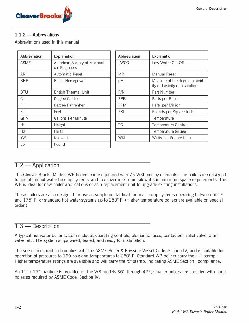
1.1.2 — Abbreviations
Abbreviations used in this manual:
1.2 — Application
The Cleaver-Brooks Models WB boilers come equipped with 75 WSI Incoloy elements. The boilers are designed to operate in hot water heating systems, and to deliver maximum kilowatts in minimum space requirements. The WB is ideal for new boiler applications or as a replacement unit to upgrade existing installations.
These boilers are also designed for use as supplemental heat for heat pump systems operating between 55° F and 175° F, or standard hot water systems up to 250° F. (Higher temperature boilers are available on special order.)
1.3 — Description
A typical hot water boiler system includes operating controls, elements, fuses, contactors, relief valve, drain valve, etc. The system ships wired, tested, and ready for installation.
The vessel construction complies with the ASME Boiler & Pressure Vessel Code, Section IV, and is suitable for operation at pressures to 160 psig and temperatures to 250° F. Standard WB boilers carry the “H” stamp. Higher temperature ratings are available and will carry the "S" stamp, indicating ASME Section I compliance.
An 11” x 15” manhole is provided on the WB models 361 through 422, smaller boilers are supplied with hand-holes as required by ASME Code, Section IV.
Abbreviation Explanation Abbreviation Explanation
ASME American Society of Mechani-cal Engineers
LWCO Low Water Cut Off
AR Automatic Reset MR Manual Reset
BHP Boiler Horsepower pH Measure of the degree of acid-ity or basicity of a solution
BTU British Thermal Unit P/N Part Number
C Degree Celsius PPB Parts per Billion
F Degree Fahrenheit PPM Parts per Million
Ft Feet PSI Pounds per Square Inch
GPM Gallons Per Minute T Temperature
Ht Height TC Temperature Control
Hz Hertz TI Temperature Gauge
kW Kilowatt WSI Watts per Square Inch
Lb Pound
1-2 750-136Model WB Electric Boiler Manual
1.3 — Description
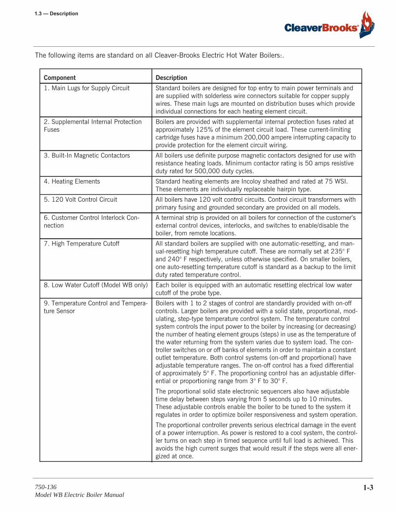
The following items are standard on all Cleaver-Brooks Electric Hot Water Boilers:.
Component Description
1. Main Lugs for Supply Circuit Standard boilers are designed for top entry to main power terminals and are supplied with solderless wire connectors suitable for copper supply wires. These main lugs are mounted on distribution buses which provide individual connections for each heating element circuit.
2. Supplemental Internal Protection Fuses
Boilers are provided with supplemental internal protection fuses rated at approximately 125% of the element circuit load. These current-limiting cartridge fuses have a minimum 200,000 ampere interrupting capacity to provide protection for the element circuit wiring.
3. Built-In Magnetic Contactors All boilers use definite purpose magnetic contactors designed for use with resistance heating loads. Minimum contactor rating is 50 amps resistive duty rated for 500,000 duty cycles.
4. Heating Elements Standard heating elements are Incoloy sheathed and rated at 75 WSI. These elements are individually replaceable hairpin type.
5. 120 Volt Control Circuit All boilers have 120 volt control circuits. Control circuit transformers with primary fusing and grounded secondary are provided on all models.
6. Customer Control Interlock Con-nection
A terminal strip is provided on all boilers for connection of the customer’s external control devices, interlocks, and switches to enable/disable the boiler, from remote locations.
7. High Temperature Cutoff All standard boilers are supplied with one automatic-resetting, and man-ual-resetting high temperature cutoff. These are normally set at 235° F and 240° F respectively, unless otherwise specified. On smaller boilers, one auto-resetting temperature cutoff is standard as a backup to the limit duty rated temperature control.
8. Low Water Cutoff (Model WB only) Each boiler is equipped with an automatic resetting electrical low water cutoff of the probe type.
9. Temperature Control and Tempera-ture Sensor
Boilers with 1 to 2 stages of control are standardly provided with on-off controls. Larger boilers are provided with a solid state, proportional, mod-ulating, step-type temperature control system. The temperature control system controls the input power to the boiler by increasing (or decreasing) the number of heating element groups (steps) in use as the temperature of the water returning from the system varies due to system load. The con-troller switches on or off banks of elements in order to maintain a constant outlet temperature. Both control systems (on-off and proportional) have adjustable temperature ranges. The on-off control has a fixed differential of approximately 5° F. The proportioning control has an adjustable differ-ential or proportioning range from 3° F to 30° F.
The proportional solid state electronic sequencers also have adjustable time delay between steps varying from 5 seconds up to 10 minutes. These adjustable controls enable the boiler to be tuned to the system it regulates in order to optimize boiler responsiveness and system operation.
The proportional controller prevents serious electrical damage in the event of a power interruption. As power is restored to a cool system, the control-ler turns on each step in timed sequence until full load is achieved. This avoids the high current surges that would result if the steps were all ener-gized at once.
750-136Model WB Electric Boiler Manual
1-3
General Description
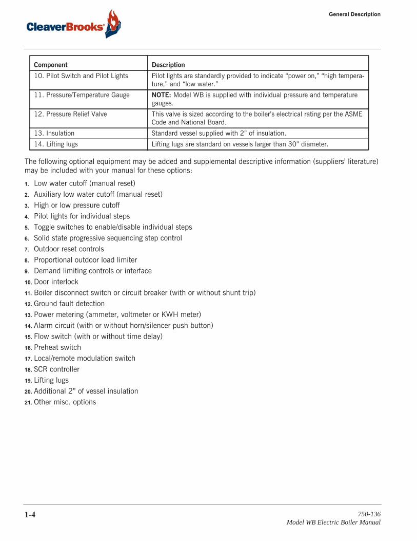
The following optional equipment may be added and supplemental descriptive information (suppliers’ literature) may be included with your manual for these options:
1. Low water cutoff (manual reset)2. Auxiliary low water cutoff (manual reset)3. High or low pressure cutoff4. Pilot lights for individual steps5. Toggle switches to enable/disable individual steps6. Solid state progressive sequencing step control7. Outdoor reset controls8. Proportional outdoor load limiter9. Demand limiting controls or interface10. Door interlock11. Boiler disconnect switch or circuit breaker (with or without shunt trip)12. Ground fault detection13. Power metering (ammeter, voltmeter or KWH meter)14. Alarm circuit (with or without horn/silencer push button)15. Flow switch (with or without time delay)16. Preheat switch17. Local/remote modulation switch18. SCR controller19. Lifting lugs20. Additional 2” of vessel insulation21. Other misc. options
10. Pilot Switch and Pilot Lights Pilot lights are standardly provided to indicate “power on,” “high tempera-ture,” and “low water.”
11. Pressure/Temperature Gauge NOTE: Model WB is supplied with individual pressure and temperature gauges.
12. Pressure Relief Valve This valve is sized according to the boiler’s electrical rating per the ASME Code and National Board.
13. Insulation Standard vessel supplied with 2” of insulation.
14. Lifting lugs Lifting lugs are standard on vessels larger than 30” diameter.
Component Description
1-4 750-136Model WB Electric Boiler Manual
1.4 — Principles of Operation
Your Dimension Drawings (DD) and Wiring Diagrams (WD) will show the optional equipment on your boiler.
1.4 — Principles of Operation
Water passes through a steel drum (vessel) containing resistance type heating elements. As the water circulates, it absorbs heat from the heating elements. The heated water is then circulated through the external system to heat buildings, to provide heat for manufacturing processes, or for use wherever it is required.
Cleaver-Brooks boilers are designed to keep water volume as low as possible to provide close control and rapid response to the heating needs. Close temperature control of the water is maintained by turning off or on, groups of resistance elements. Controls in the boiler automatically select the number of heating element groups (or steps) needed to maintain the water temperature, while supplying the system’s heat demands.
NOTE: Although circulation pumps are not supplied with these boilers, they should, however, be sized to provide a flow rate adequate to deliver the boiler’s full output to the system, without high boiler temperature rise (100° F). Pumps should operate continuously and, for the best control, the flow through the boiler should be constant.
750-136Model WB Electric Boiler Manual
1-5

General Description
1-6 750-136Model WB Electric Boiler Manual
CHAPTER 2 Installation Instructions
2.1 — Receiving Inspection
Each boiler is completely inspected at the factory and carefully crated for shipment. Inspect the packing for signs of exterior damage. After placing the unit as close as possible to the point of actual installation, uncrate carefully and check all boxes and cartons against the packing slip. In case of damage or shortage, notify the carrier imme-diately.
2.2 — Location
Consult local codes for specific requirements. Refer to the Dimensional Drawings (DD) and Wiring Diagrams (WD) prepared by Cleaver-Brooks for your specific installation. Position the boiler to provide adequate clearance on all sides for necessary access when operating and servicing the boiler.
Installation should be performed only by qualified personnel who are familiar with this equipment.
Before proceeding, make sure you read and understand the contents of this manual.
To avoid damage to the equipment, be sure to:
1. Check your local electrical code for minimum clearances required around electrical equipment.
2. For installation in a closet, provide ventilation openings of 200 square inches per 100KW of boiler rating.
3. Observe local codes, which may specify greater clearances over top of boiler and must take precedent.
4. Install indoors only.
! Warning
! Caution
750-136Model WB Electric Boiler Manual
2-1
Installation Instructions
2.3 — Piping
This boiler is intended for use on forced circulation systems with a pump of adequate capacity to overcome the system head loss (pressure drop at required flow rate), and to provide a flow rate adequate to permit the boiler to generate its full heat output. Radiators and convectors in the system must have adequate capacity to dissipate the boiler output at system design operating water temperature.
The pressure drop through the boiler is equivalent to the pressure drop through 30 feet of pipe equal to the diameter of the inlet and outlet fittings.
Failure to provide adequate radiator capacity may create a low flow rate through the boiler, raising the tempera-ture too high, and will result in “short cycling” of the boiler due to operation at the limiting or maximum tempera-ture. This also will prevent the boiler from supplying its rated output to the system.
Tight-closing valves should be installed on the inlet and outlet piping to facilitate isolating the boiler from the sys-tem for annual boiler internal inspection and/or repair that requires the boiler to be drained.
An expansion tank should be provided with a volume equal to 1/16 of the total water volume of the system, inclusive of the boiler vessel, radiators, coils, and all piping. The expansion tank may be connected to the fitting provided on top of the boiler vessel. If another location for the expansion tank connection is used, the boiler opening must be plugged.
An air vent and an air separator should also be installed to eliminate air in the system.
Water for make-up during operation should be added manually or automatically directly to the expansion tank.
The boiler drain valve should be piped to the drain.
2.4 — Heat Pump Systems with High Flow Rates
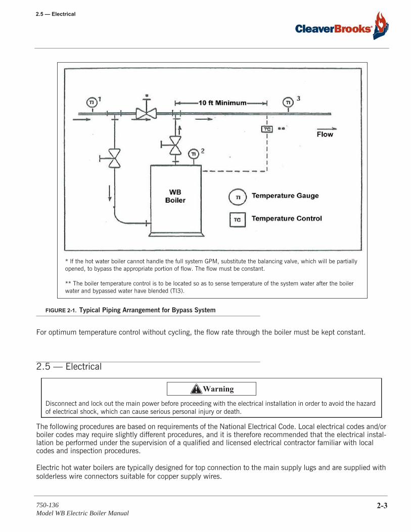
The Model WB will accept flow rates that will give a minimum temperature rise across the boiler as low as 3° F. Minimum temperature rise can also be obtained by installing a bypass piping arrangement to adjust the flow through the boiler.
Use the following formula to determine the maximum and minimum flow rates of a given boiler:
FLOW (GPM) = KW x 6.816 T
where T is equal to any temperature rise between 3° F and 30° F, as indicated by TI1 and TI2 in Figure 2-1.
If the system flow rate is greater, a bypass around the boiler with a balancing cock or globe valve will be required to bypass the appropriate portion of the system flow.
The relief valve outlet should be piped to a safe point of discharge - where no risk to personnel, or impaired access to the boiler controls, would result from unexpected discharge of hot water from the relief valve.
! Warning
2-2 750-136Model WB Electric Boiler Manual
2.5 — Electrical
FIGURE 2-1. Typical Piping Arrangement for Bypass System
For optimum temperature control without cycling, the flow rate through the boiler must be kept constant.
2.5 — Electrical
The following procedures are based on requirements of the National Electrical Code. Local electrical codes and/or boiler codes may require slightly different procedures, and it is therefore recommended that the electrical instal-lation be performed under the supervision of a qualified and licensed electrical contractor familiar with local codes and inspection procedures.
Electric hot water boilers are typically designed for top connection to the main supply lugs and are supplied with solderless wire connectors suitable for copper supply wires.
Disconnect and lock out the main power before proceeding with the electrical installation in order to avoid the hazard of electrical shock, which can cause serious personal injury or death.
* If the hot water boiler cannot handle the full system GPM, substitute the balancing valve, which will be partially opened, to bypass the appropriate portion of flow. The flow must be constant.
** The boiler temperature control is to be located so as to sense temperature of the system water after the boiler water and bypassed water have blended (TI3).
! Warning
750-136Model WB Electric Boiler Manual
2-3

Installation Instructions
If aluminum supply wires are selected, Cleaver-Brooks strongly recommends that the installing electrical contrac-tor splice a short length of copper wire to the aluminum supply conductors and terminate this copper wire in the main supply lugs on the unit. If copper splices are not used and the customer chooses to terminate the alumi-num supply wires directly in the main supply lugs, the following points should be carefully followed:
• An oxide inhibitor paste should be applied liberally to the conductors.• The main supply lugs should be tightened (with power off) every 24 hours for the first week of operation.• After the first week, the main supply lugs should be tightened (with power off) once every 30 days.• After the first 30 days of operation, all electrical power connections should be tightened (with power off).
Power wiring should be selected for high temperature use (minimum wire rating, 75° C, per National electrical Code) and/or per local electrical codes.
2.5.1 — Electrical Installation Checklist
The following procedures are recommended:1. Check the boiler nameplate for the boiler kilowatt rating, voltage, and amperage.2. Check the electrical supply voltage to verify that it conforms to the boiler requirements, and that sufficient cir-
cuit capacity is available for the boiler.3. Refer to the boiler Wiring Diagram (WD), included with the boiler, for the number and rating of supply circuits
required by the boiler.4. Refer to your local electrical code for proper wire and conduit sizes for these ratings.5. Install wiring from the feeder switch or circuit breaker to the boiler, and connect to the bus assembly as indi-
cated on the boiler Wiring Diagram (WD).6. All Cleaver-Brooks Electric Boilers are supplied with factory-mounted magnetic contactors, and all internal cir-
cuits are factory installed and tested.
7. Check all electrical connections for tightness. Vibration during transit sometimes loosens connections.
Before tightening the main supply lugs, disconnect and lockout main power to avoid the hazard of electrical shock, which can cause serious personal injury or death.
Main supply lugs should be tightened every 24 hours during the first week of operation. After the first week, the main supply lugs should be tightened once every 30 days. After the first 30 days of operation, all electrical power connec-tions should be tightened (with power off).
! Warning
! Caution
2-4 750-136Model WB Electric Boiler Manual
2.5 — Electrical
2.5.2 — Recommended Torque Settings
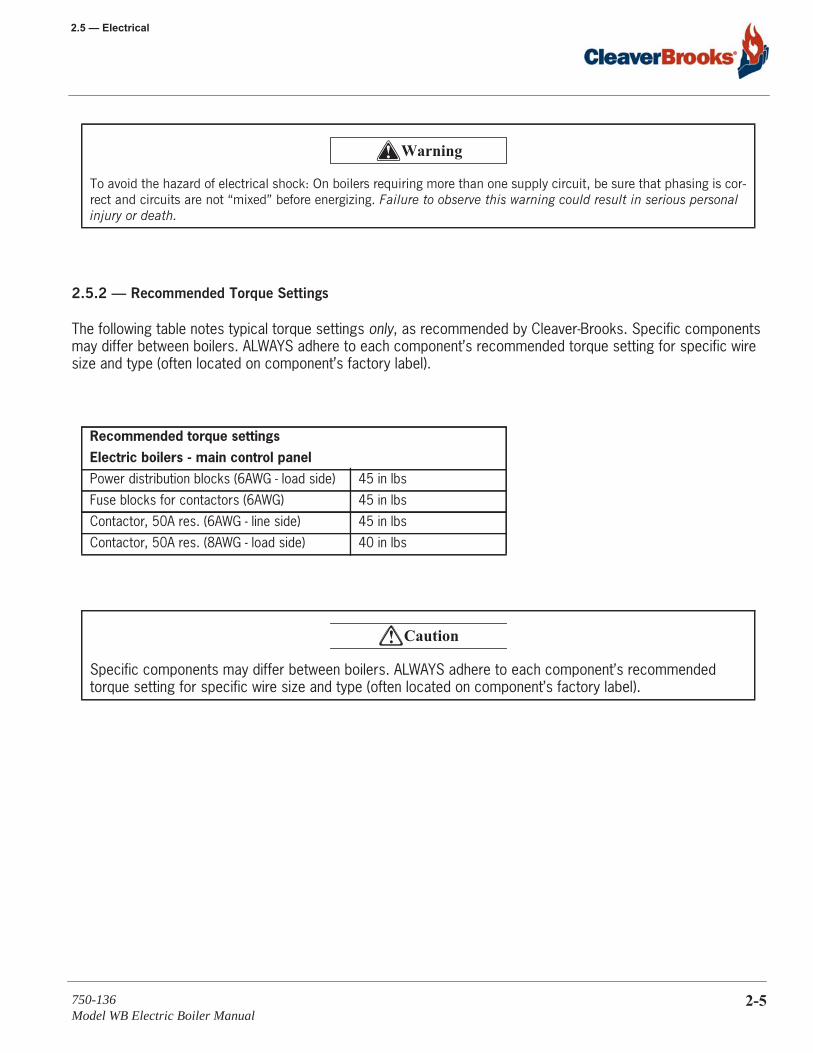
The following table notes typical torque settings only, as recommended by Cleaver-Brooks. Specific components may differ between boilers. ALWAYS adhere to each component’s recommended torque setting for specific wire size and type (often located on component’s factory label).
To avoid the hazard of electrical shock: On boilers requiring more than one supply circuit, be sure that phasing is cor-rect and circuits are not “mixed” before energizing. Failure to observe this warning could result in serious personal injury or death.
Recommended torque settingsElectric boilers - main control panelPower distribution blocks (6AWG - load side) 45 in lbs
Fuse blocks for contactors (6AWG) 45 in lbs
Contactor, 50A res. (6AWG - line side) 45 in lbs
Contactor, 50A res. (8AWG - load side) 40 in lbs
Specific components may differ between boilers. ALWAYS adhere to each component’s recommended torque setting for specific wire size and type (often located on component’s factory label).
! Warning
! Caution
750-136Model WB Electric Boiler Manual
2-5

Installation Instructions
2-6 750-136Model WB Electric Boiler Manual
CHAPTER 3 Pre-Start Preparation
3.1 — Inspection
Boilers which have been exposed to dust, wet and/or humid conditions must be thoroughly cleaned and dried out. Otherwise, the buildup of dust and rust on the contactors, or moisture at the terminal end of the elements, may result in severe damage.
The following precautions must be undertaken:
1. Make certain all electrical connections and element terminals are thoroughly cleaned, dried, and checked for loose connections.
2. Inspect all contactors, fuse bases, and wire bundles for stray or loose metal objects (screws, bolts, metal shavings, knockout slugs, etc.) that may lodge there. All such material must be removed before startup.
3. There is a very high probability that, during shipment or storage prior to operation, the elements will accumu-late moisture. The moisture will turn to steam when the elements are energized, rupturing the element casing.
Make certain that you have read and understand Chapters 1 and 2 before proceeding.
Pre-startup should be performed by a qualified technician who is familiar with this equipment.
Failure to heed this warning may result in serious personal injury or death.
Disconnect and lock out the main power to avoid the hazard of electrical shock.
Moisture in the element may result in damage to the element.
! Warning
! Warning
! Caution
750-136Model WB Electric Boiler Manual
3-1
Pre-Start Preparation
To check for this condition, take a reading with an ohmmeter between one of the contactor terminals (load side) to ground for each contactor. If the reading is less than 17,000 ohms for standard 3-phase connection, or 50,000 ohms for a single element, remove the fuses going to that contactor so that, during the first day’s opera-tion, the low reading elements will not be energized, but will be heated by other dry elements and the moisture driven out at a controlled rate.
There are alternate heating methods. Direct a heat lamp at the offending elements or remove the element assem-bly, bake it in a 200º F oven for 8 hours, then reinstall and rewire. Following any of these procedures, the sup-port element then may be put in operation by replacing the fuses after the elements have been rechecked with an ohmmeter.
3.2 — Boiler and System Cleaning
One important phase in completing hot water heating installations and boiler startup is cleaning the system.
No matter how carefully a system is constructed, certain extraneous materials could find their way into the boiler. Pipe dope, thread cutting oils, soldering flux, rust preventatives, soldering compounds, core sand, welding slag, and dirt, sand or clays from the jobsite usually are found.
Cleaning a hot water system (either steel or copper piping) is neither difficult nor expensive. The three most com-mon materials used for cleaning are:
a. Trisodium Phosphate (TSP)
b. Sodium Carbonate
c. Sodium Hydroxide (Lye)
Their preference is in the order shown. Prepare the cleaning solutions as follows, do not mix different types of cleaners.
a. Trisodium Phosphate: one pound for each fifty gallons in the system.
b. Sodium Carbonate: one pound for each thirty gallons in the system.
c. Sodium Hydroxide: one pound for each fifty gallons in the system.
Disconnect and lockout the main power to avoid the hazard of electrical shock, which could cause serious personal injury or death.
NOTE: Check local codes for restrictions on the use of TSP.
NOTE: Do not use Sodium Hydroxide for copper or galvanized systems.
! Warning
3-2 750-136Model WB Electric Boiler Manual

3.3 — Boiler Water Treatment
Fill, vent, and circulate the system with the selected solution, allowing it to reach operating temperatures if pos-sible. After circulating for three hours, drain the system completely and refill it with fresh water. Usually enough of the cleaner will adhere to the piping to give an alkaline solution satisfactory for operation. A pH reading between 8.5 and 9.5 is preferred, and a small amount of cleaner can be added if necessary to raise the pH value.
Certain conditions are definite indications of an unclean system. See the checklist below. If any of these condi-tions occurs when filling the system, the boiler and associated system piping need cleaning.
Obviously discolored, dirty water.
A pH or alkalinity test that gives a pH test reading below 7. (Below 7 indicates water in the system is acidic and corrosive.)
The appearance of dirty foam or scum lines on the surface.
In some cases, there are sufficient quantities of such materials to break down chemically during the operation of the system, causing gas formation and acidic system water. All such materials should be removed.
Hot water systems, in most cases, naturally operate with a pH of 8.5 or higher. If a system indicates pH values below 7 on the scale, the following symptoms may occur:
• Gas formation in the system. • Pump seal and gland problems.• Air vent sticking and leaking.• Piping leaks at the joints.
If system deterioration is permitted and leaks develop and water losses increase, it is possible to cause serious damage to the boiler. Therefore, it’s important to have a closed system that is clean, neutral, and water tight.
3.3 — Boiler Water Treatment
Water treatment is required to prevent depositing of scale and to prevent corrosion from acids, oxygen, and other harmful elements that may be in the water supply. Contact your Cleaver-Brooks local representative for more information on a water treatment program.
Objectives of boiler water conditioning include:
• Prevent the accumulation of scale and deposits in both the boiler and heating system.• Remove dissolved gases from the water.
Cleaning compounds are hazardous; protective clothing and personal protective equipment must be worn when mix-ing or handling chemicals and chemical solutions.
! Warning
750-136Model WB Electric Boiler Manual
3-3
Pre-Start Preparation
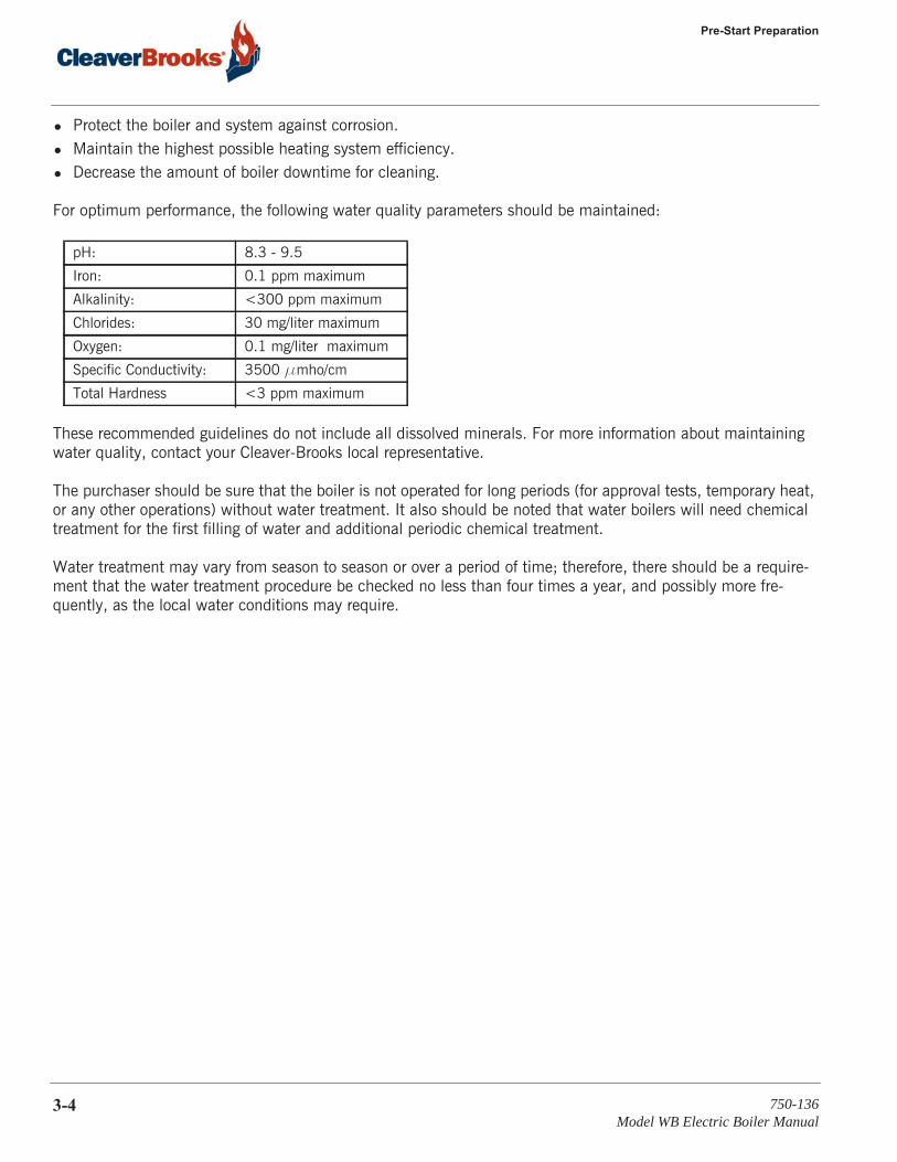
• Protect the boiler and system against corrosion.• Maintain the highest possible heating system efficiency.• Decrease the amount of boiler downtime for cleaning.
For optimum performance, the following water quality parameters should be maintained:
These recommended guidelines do not include all dissolved minerals. For more information about maintaining water quality, contact your Cleaver-Brooks local representative.
The purchaser should be sure that the boiler is not operated for long periods (for approval tests, temporary heat, or any other operations) without water treatment. It also should be noted that water boilers will need chemical treatment for the first filling of water and additional periodic chemical treatment.
Water treatment may vary from season to season or over a period of time; therefore, there should be a require-ment that the water treatment procedure be checked no less than four times a year, and possibly more fre-quently, as the local water conditions may require.
pH: 8.3 - 9.5
Iron: 0.1 ppm maximum
Alkalinity: <300 ppm maximum
Chlorides: 30 mg/liter maximum
Oxygen: 0.1 mg/liter maximum
Specific Conductivity: 3500 mmho/cm
Total Hardness <3 ppm maximum
3-4 750-136Model WB Electric Boiler Manual

CHAPTER 4 Operating Instructions
4.1 — Initial Startup
1. Close the control cabinet doors.2. Ensure the control power switch is in the OFF position. Close the main power switch(es).3. Fill the vessel and the system with water, open the air vent at the highest point in the system to allow air
evacuation, and close the valve. Start the system circulation pump. Check to see that the system pressure is within the design range for the boiler and associated equipment.
4. Set the high limit temperature controls. Suggested setting is 20°F above operating temperature. The boiler must not exceed a maximum of 250°F per ASME BPVC, Section IV.
5. Set the required temperature setpoint on the temperature control.a. Operating (On/Off) Control
The temperature control on standard boilers up to two (2) stages is operated via operating (on/off) control switches; these controls have setpoint and differential ranges as noted in Figure 4.1.
FIGURE 4-1. Operating Temperature Controls
Make certain all pre-start procedures listed in Chapter 3 have been completed prior to reading this chapter. Failure to heed this warning may result in serious personal injury or death.
Before gaining access to electrical wiring or controls, lock out and disconnect the boiler’s main power to avoid the hazard of electrical shock.
! Warning
Cleaver-BrooksPart Number
Setting Range[°F]
Differential[°F]
ResetFunction
817-04100-000 122 – 210 9 – 27 Automatic
817-04101-000 176 – 240 9 – 45 Automatic
750-136Model WB Electric Boiler Manual
4-1
Operating Instructions
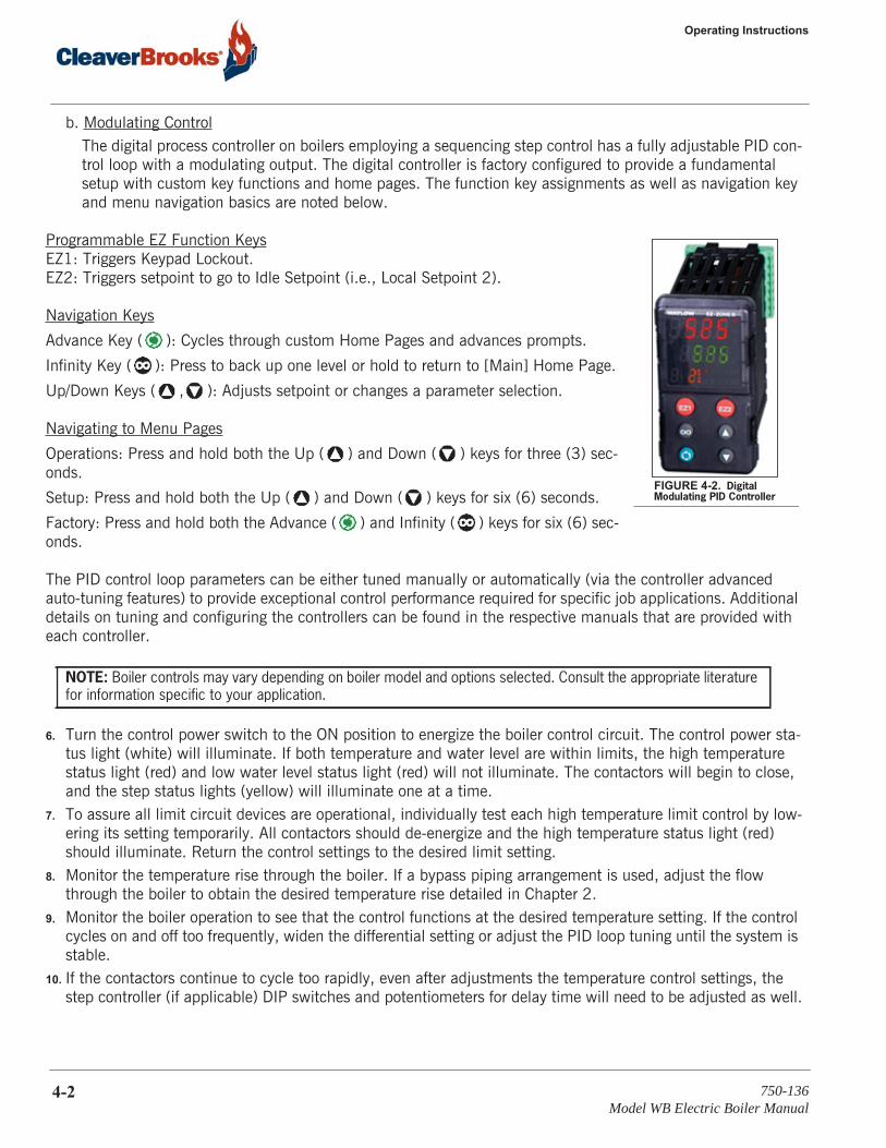
b. Modulating ControlThe digital process controller on boilers employing a sequencing step control has a fully adjustable PID con-trol loop with a modulating output. The digital controller is factory configured to provide a fundamental setup with custom key functions and home pages. The function key assignments as well as navigation key and menu navigation basics are noted below.
Programmable EZ Function KeysEZ1: Triggers Keypad Lockout.EZ2: Triggers setpoint to go to Idle Setpoint (i.e., Local Setpoint 2).
Navigation Keys
Advance Key ( ): Cycles through custom Home Pages and advances prompts.
Infinity Key ( ): Press to back up one level or hold to return to [Main] Home Page.
Up/Down Keys ( , ): Adjusts setpoint or changes a parameter selection.
Navigating to Menu Pages
Operations: Press and hold both the Up ( ) and Down ( ) keys for three (3) sec-onds.
Setup: Press and hold both the Up ( ) and Down ( ) keys for six (6) seconds.
Factory: Press and hold both the Advance ( ) and Infinity ( ) keys for six (6) sec-onds.
The PID control loop parameters can be either tuned manually or automatically (via the controller advanced auto-tuning features) to provide exceptional control performance required for specific job applications. Additional details on tuning and configuring the controllers can be found in the respective manuals that are provided with each controller.
6. Turn the control power switch to the ON position to energize the boiler control circuit. The control power sta-tus light (white) will illuminate. If both temperature and water level are within limits, the high temperature status light (red) and low water level status light (red) will not illuminate. The contactors will begin to close, and the step status lights (yellow) will illuminate one at a time.
7. To assure all limit circuit devices are operational, individually test each high temperature limit control by low-ering its setting temporarily. All contactors should de-energize and the high temperature status light (red) should illuminate. Return the control settings to the desired limit setting.
8. Monitor the temperature rise through the boiler. If a bypass piping arrangement is used, adjust the flow through the boiler to obtain the desired temperature rise detailed in Chapter 2.
9. Monitor the boiler operation to see that the control functions at the desired temperature setting. If the control cycles on and off too frequently, widen the differential setting or adjust the PID loop tuning until the system is stable.
10. If the contactors continue to cycle too rapidly, even after adjustments the temperature control settings, the step controller (if applicable) DIP switches and potentiometers for delay time will need to be adjusted as well.
NOTE: Boiler controls may vary depending on boiler model and options selected. Consult the appropriate literature for information specific to your application.
FIGURE 4-2. Digital Modulating PID Controller
4-2 750-136Model WB Electric Boiler Manual
4.1 — Initial Startup
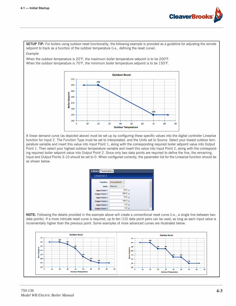
SETUP TIP: For boilers using outdoor reset functionality, the following example is provided as a guideline for adjusting the remote setpoint to track as a function of the outdoor temperature (i.e., defining the reset curve).
Example
When the outdoor temperature is 20°F, the maximum boiler temperature setpoint is to be 200°F.When the outdoor temperature is 70°F, the minimum boiler temperature setpoint is to be 150°F.
A linear demand curve (as depicted above) must be set up by configuring these specific values into the digital controller Linearize function for Input 2. The Function Type must be set to Interpolated, and the Units set to Source. Select your lowest outdoor tem-perature variable and insert this value into Input Point 1, along with the corresponding required boiler setpoint value into Output Point 1. Then select your highest outdoor temperature variable and insert this value into Input Point 2, along with the correspond-ing required boiler setpoint value into Output Point 2. Since only two data points are required to define the line, the remaining Input and Output Points 3-10 should be set to 0. When configured correctly, the parameter list for the Linearize function should be as shown below.
NOTE: Following the details provided in the example above will create a conventional reset curve (i.e., a single line between two data points). If a more intricate reset curve is required, up to ten (10) data point pairs can be used, as long as each input value is incrementally higher than the previous point. Some examples of more advanced curves are illustrated below.
750-136Model WB Electric Boiler Manual
4-3
Operating Instructions
4.2 — Maintenance Schedule
4.2.1 — Weekly Procedure
Tighten the main supply lugs every 24 hours during the first week of operation.
4.2.2 — Quarterly Procedures
While the boiler is operating, lower the temperature setting drastically on the temperature control and listen for the magnetic contactors to open. Then return the setting to normal and again listen for the magnetic contactors to operate.
Turn off the control pilot switch and the main power supply switch. This is done as a safety measure to prevent accidental turn-on of power.
Tighten all the electrical connections that could have loosened due to heat expansion and contraction. Pay par-ticular attention to the main lugs that receive the power circuit. Examine all the relays and the magnetic contac-tors for pitting, corrosion, burned or welded contacts, or inoperative 120 volt coils. Inspect for blown fuses or discoloration of fuse clips, which would indicate a loose fit. Correct malfunctions as required.
If all the elements have been operating normally and each element bank draws its rated current or amperage, where:
AMPS (3-phase) = Watts Volts x 1.73
no further element tests are necessary. However, if there is a low or unbalanced amp reading, further tests with an ohmmeter may be necessary to detect the open or shorted element(s) in the group. To test individual ele-ments for continuity with an ohmmeter, the jumpers between elements must first be removed.
4.2.3 — Annual Procedure
The boiler should be drained and cleaned to remove any accumulated scale or sludge. This normally can be done concurrently with an annual inspection. More frequent cleaning may be required if the boiler supply water con-tains sediment or if a considerable amount of make-up water is used to replace system losses. The annual check-out and start-up procedure is otherwise identical with the aforementioned monthly and quarterly procedure.
NOTE: Only personnel who have a working knowledge and understanding of this equipment should have access to the control cabinet.
Lockout and disconnect the boiler’s main power to avoid the hazard of electrical shock, which could result in serious personal injury or death.
When checking the element terminal connections, use wrenches on both nuts to avoid twisting the terminal stud and damage to the equipment.
! Warning
! Caution
4-4 750-136Model WB Electric Boiler Manual
4.3 — Element Replacement Procedure
4.3 — Element Replacement Procedure
4.3.1 — Heating Elements
The individually replaceable Cleaver-Brooks electric heating elements are readily accessible for fast, easy, on-the-job maintenance. They can be removed and replaced with standard tools. The small physical size of each ele-ment means the element bundle is lighter and simpler to remove. Element Bundles are mounted horizontally for convenient access.
4.3.2 — Element Replacement
1. Make a sketch or a drawing of the element bussing and tag the wires to simplify re-connection later. Refer to the wiring diagram supplied by Cleaver-Brooks for your installation.
2. Disconnect the wires and remove the element assembly flange bolts.
3. Remove the element assembly by pulling it straight out.4. Remove the jumper wires and remove the brass ferrule nuts.5. Slide the element toward the dry side (about 2”) to expose the brass ferrules on the element. Cut off the fer-
rules with a hacksaw. Slide the element out of the steel flange toward the wet side.6. Inspect and clean the thread and the seat of the steel flange where the new ferrules will seal. If seats are pit-
ted or rusted, it may not be possible to seal the new elements; therefore, a new flange may be required.7. Screw the new ferrule nuts (furnished with a replacement element) into the cleaned or new flange plate (finger
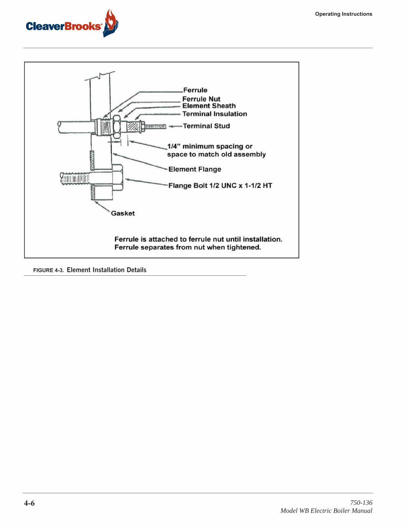
tight).8. Slide the element into position. Make sure the element protrudes beyond the ferrule nut approximately 1/4”,
or to match original assembly. Some boiler models require the element sheath to extend out further than 1/4”, so duplicate the original assembly as closely as possible.
9. Hold the element to prevent twisting while tightening the ferrule nuts. Tighten the nuts to approximately 45 ft. lbs. (35 ft. lbs. for 208 and 240 volt elements). You will feel the ferrule separate from the nut while tighten-ing. A properly tightened ferrule nut will have separated from its ferrule and the ferrule will be squeezed or compressed onto the element sheath, thus providing a tight seal.
10. Replace the element assembly into the boiler, using a new gasket and anti-seize compound on gaskets and bolts. Torque the element flange bolts to 90 to 100 ft. lbs.
11. When the boiler is filled and pressurized, inspect for leaks. If leaks are detected around the brass ferrules, tighten the nuts in 5 ft lb increments up to a maximum of 70 ft lb (60 ft lb for 208 and 240 Volt elements) until leaks are no longer detected.
12. Rewire the element ends. Torque element stud nuts to 35 in lb.
Before element replacement, make certain the boiler is drained below the element opening and lock out and discon-nect the boiler’s main power to avoid the hazard of electrical shock, which could result in serious personal injury or death.
NOTE: To assist in breaking free the gasket, insert one of the flange bolts into the tapped hole provided.
NOTE: Since the elements often differ in length, check to assure that there is an adequate clearance (3/4” min.) between the end of the element and the opposite side vessel wall. Check by measuring both the element extension (from flange to tip) and the distance from the tank flange face to the vessel wall.
! Warning
750-136Model WB Electric Boiler Manual
4-5
Operating Instructions
FIGURE 4-3. Element Installation Details
4-6 750-136Model WB Electric Boiler Manual
CHAPTER 5 Troubleshooting
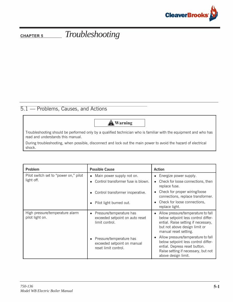
5.1 — Problems, Causes, and Actions
Troubleshooting should be performed only by a qualified technician who is familiar with the equipment and who has read and understands this manual.
During troubleshooting, when possible, disconnect and lock out the main power to avoid the hazard of electrical shock.
Problem Possible Cause Action
Pilot switch set to “power on,” pilot light off.
• Main power supply not on.
• Control transformer fuse is blown.
• Control transformer inoperative.
• Pilot light burned out.
• Energize power supply.
• Check for loose connections, then replace fuse.
• Check for proper wiring/loose connections, replace transformer.
• Check for loose connections, replace light.
High pressure/temperature alarm pilot light on.
• Pressure/temperature has exceeded setpoint on auto reset limit control.
• Pressure/temperature has exceeded setpoint on manual reset limit control.
• Allow pressure/temperature to fall below setpoint less control differ-ential. Raise setting if necessary, but not above design limit or manual reset setting.
• Allow pressure/temperature to fall below setpoint less control differ-ential. Depress reset button. Raise setting if necessary, but not above design limit.
! Warning
750-136Model WB Electric Boiler Manual
5-1
Troubleshooting
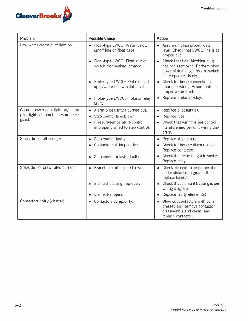
Low water alarm pilot light on. • Float-type LWCO: Water below cutoff line on float cage.
• Float-type LWCO: Float stuck/switch mechanism jammed.
• Probe-type LWCO: Probe circuit open/water below cutoff level.
• Probe-type LWCO: Probe or relay faulty.
• Assure unit has proper water level. Check that LWCO line is at proper level.
• Check that float blocking plug has been removed. Perform blow-down of float cage. Assure switch plate operates freely.
• Check for loose connections/improper wiring. Assure unit has proper water level.
• Replace probe or relay.
Control power pilot light on, alarm pilot lights off, contactors not ener-gized.
• Alarm pilot light(s) burned out.
• Step control fuse blown.
• Pressure/temperature control improperly wired to step control.
• Replace pilot light(s).
• Replace fuse.
• Check that wiring is per control literature and per unit wiring dia-gram.
Steps do not all energize. • Step control faulty.
• Contactor coil inoperative.
• Step control relay(s) faulty.
• Replace step control.
• Check for loose coil connection. Replace contactor.
• Check that relay is tight in socket. Replace relay.
Steps do not draw rated current • Branch circuit fuse(s) blown.
• Element bussing improper.
• Element(s) open.
• Check element(s) for proper ohms and resistance to ground then replace fuse(s).
• Check that element bussing is per wiring diagram.
• Replace faulty element(s).
Contactors noisy (chatter). • Contactors damp/dirty. • Blow out contactors with com-pressed air. Remove contactor, disassemble and clean, and replace contactor.
Problem Possible Cause Action
5-2 750-136Model WB Electric Boiler Manual
CHAPTER 6 Parts
6.1 — Ordering Parts
Be sure to furnish complete information when ordering parts. Include the boiler serial number (displayed on the boiler name plate) on your order. The order should state:
• Cleaver-Brooks part number• name and description of the required part• quantity required• method of shipment• date the part(s) is needed by
If repair parts are required for accessory equipment, order these parts from your local authorized Cleaver-Brooks representative.
750-136Model WB Electric Boiler Manual
6-1
Parts
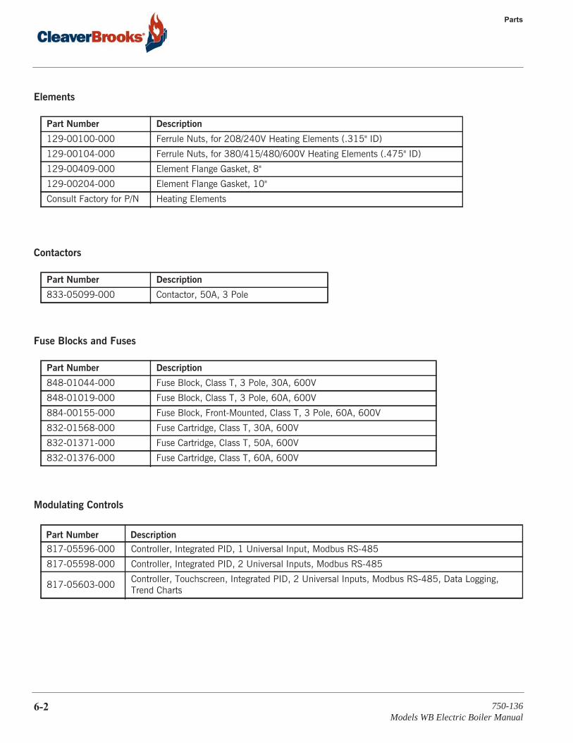
Elements
Contactors
Fuse Blocks and Fuses
Modulating Controls
Part Number Description
129-00100-000 Ferrule Nuts, for 208/240V Heating Elements (.315" ID)
129-00104-000 Ferrule Nuts, for 380/415/480/600V Heating Elements (.475" ID)
129-00409-000 Element Flange Gasket, 8"
129-00204-000 Element Flange Gasket, 10"
Consult Factory for P/N Heating Elements
Part Number Description
833-05099-000 Contactor, 50A, 3 Pole
Part Number Description
848-01044-000 Fuse Block, Class T, 3 Pole, 30A, 600V
848-01019-000 Fuse Block, Class T, 3 Pole, 60A, 600V
884-00155-000 Fuse Block, Front-Mounted, Class T, 3 Pole, 60A, 600V
832-01568-000 Fuse Cartridge, Class T, 30A, 600V
832-01371-000 Fuse Cartridge, Class T, 50A, 600V
832-01376-000 Fuse Cartridge, Class T, 60A, 600V
Part Number Description
817-05596-000 Controller, Integrated PID, 1 Universal Input, Modbus RS-485
817-05598-000 Controller, Integrated PID, 2 Universal Inputs, Modbus RS-485
817-05603-000Controller, Touchscreen, Integrated PID, 2 Universal Inputs, Modbus RS-485, Data Logging, Trend Charts
6-2 750-136Models WB Electric Boiler Manual
6.1 — Ordering Parts
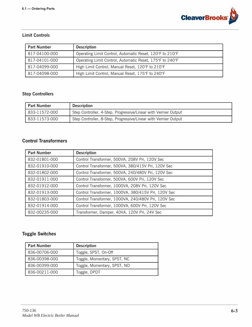
Limit Controls
Step Controllers
Control Transformers
Toggle Switches
Part Number Description
817-04100-000 Operating Limit Control, Automatic Reset, 120°F to 210°F
817-04101-000 Operating Limit Control, Automatic Reset, 175°F to 240°F
817-04099-000 High Limit Control, Manual Reset, 120°F to 210°F
817-04098-000 High Limit Control, Manual Reset, 175°F to 240°F
Part Number Description
833-11572-000 Step Controller, 4-Step, Progressive/Linear with Vernier Output
833-11573-000 Step Controller, 8-Step, Progressive/Linear with Vernier Output
Part Number Description
832-01801-000 Control Transformer, 500VA, 208V Pri, 120V Sec
832-01910-000 Control Transformer, 500VA, 380/415V Pri, 120V Sec
832-01802-000 Control Transformer, 500VA, 240/480V Pri, 120V Sec
832-01911-000 Control Transformer, 500VA, 600V Pri, 120V Sec
832-01912-000 Control Transformer, 1000VA, 208V Pri, 120V Sec
832-01913-000 Control Transformer, 1000VA, 380/415V Pri, 120V Sec
832-01803-000 Control Transformer, 1000VA, 240/480V Pri, 120V Sec
832-01914-000 Control Transformer, 1000VA, 600V Pri, 120V Sec
832-00235-000 Transformer, Damper, 40VA, 120V Pri, 24V Sec
Part Number Description
836-00706-000 Toggle, SPST, On-Off
836-00398-000 Toggle, Momentary, SPST, NC
836-00399-000 Toggle, Momentary, SPST, NO
836-00211-000 Toggle, DPDT
750-136Model WB Electric Boiler Manual
6-3

Parts
Pilot Lights
Miscellaneous
Consult factory for special/custom parts or for parts not shown on this list.
Part Number Description
881-00249-000 White, Neon Type
881-00250-000 Amber, Neon Type
881-00251-000 Red, Neon Type
Part Number Description
997-10943-000 Safety Door Interlock, 115Vac, 60Hz, for single door enclosures
997-00148-000 Safety Door Interlock, 115Vac, 60Hz, for dual door enclosures
817-00239-000 Alarm Bell, 4"
817-00468-000 Alarm Bell, 6"
817-03096-000 Alarm Horn, 4", NEMA 1
836-01461-000 Panel High-Temperature Thermostat Switch
6-4 750-136Models WB Electric Boiler Manual