hoval processvent design handbook · processvent design handbook recovery of heat from the process...
TRANSCRIPT

ProcessVentDesign handbook
Recovery of heat from the process air in production halls


ProcessVent heat PVHCompact unit for ventilating and heating production halls with heat recovery from process air
3
A
ProcessVent cool PVCCompact unit for ventilating, heating and cooling production halls with heat recovery from process air
23
B
ProcessVent PVCompact unit for ventilating production halls with heat recovery from process air
43
C
Options
57
D
Transport and installation
65
E
Control systems
71
F
System design
83
G
ProcessVent
Contents

2

3
ProcessVent heat PVHCompact unit for ventilating and heating production halls with heat recovery from process air
A
1 Use _____________________________________ 4
2 Construction and operation___________________ 4
3 Unit type reference _________________________ 8
4 Technical data _____________________________ 8
5 Specification texts _________________________ 17
ProcessVent heat
Contents

4
1 Use
1.1 Intended use
The ProcessVent unit is used to recover heat from process air and supply fresh air to halls containing enclosed machine tools or welding plants. The extract air from the extract air purification plant flows through a plate heat exchanger in an oil-tight design and is routed to the outside via a duct; the heat it contains is transferred to the supply air. Additionally equipped with a heating coil for post-heating of the supply air.
Intended use also includes compliance with the installation, commissioning, operating and servicing conditions (operating manual).Any use above and beyond this is deemed improper. The manufacturer can accept no liability for damage resulting from improper use.
1.2 User group
The unit may only be installed, operated and serviced by authorised and trained specialist personnel who are familiar with the unit and aware of the risks involved.The operating manual is intended for English-speaking oper-ating engineers and technicians and for specialist building services, heating and ventilation technology personnel.
2 Construction and operation
The ProcessVent unit forms one overall system with the extract air purification plant: The extract air purification plant draws off soiled air from machine tools or welding plants by means of a fan. It purifies this process air and transports it onwards through the extract air duct to the ProcessVent unit.
The ProcessVent unit fulfils the following functions: ■ Heating with connection to hot water supply ■ Fresh air supply ■ Extract air removal (with air conveyance via the extract air purification plant)
■ Recovery of heat from the process air ■ Recirculation operation ■ Air filtration
Machine tool
Extract air purification plant
ProcessVent
Fig. A1: The ProcessVent unit forms one overall system with the extract air purifica-tion plant.
ProcessVent heat
Use

5
A
B
C
D
E
F
G
2.1 Construction
Heating coil
Plate heat exchanger condensate connection
Access door, extract air
Duct connection, extract air
Supply air fans
Fresh air filter (class F7) with filter monitoring
Duct connection, fresh air
Access door, fresh air
Control box
Plate heat exchanger with frost monitoring
ER and bypass damper with continuous actuator
Duct connection, exhaust air
Recirculation air inlet
Fresh air/recirculation damper with continuous actuator
Access door, exhaust air
Access panels, supply air (on all sides)
Supply air duct connection, rear
Fig. A2: Unit construction
ProcessVent heat
Construction and operation

6
2.2 Operational diagram
Exhaust air
Temperature sensor, energy monitoring (optional)
Heating coil with frost controller
Supply air sensor
Supply air
Recirculation
Plate heat exchanger with differential pressure switch
ER/bypass damper with actuator
Mixed air sensor
Fresh air
Fresh air/recirculation damper with actuator
Fresh air filter with differential pressure switch
Supply air fans with volume flow monitoring
Condensate connection
Extract air sensor
Extract air
Fresh air sensor
Room air sensor
Fig. A3: Operational diagram
ProcessVent heat
Construction and operation

7
A
B
C
D
E
F
G
2.3 Operating modes
The unit has the following operating modes: ■ Ventilation ■ Supply air ■ Recirculation
■ Recirculation night ■ Night cooling summer ■ Off
The ProcessNet control system or the higher-level building management system controls the overall plant automatically. The operating mode of the ProcessVent units depends on:
■ the time programme ■ the operating states of the machines from which the
process air is to be drawn off
The following applies: When the machines are in operation, the ProcessVent unit always works in 'Ventilation' mode. The operating mode defined in the time programme is overridden.You can also control the operating mode of the ProcessVent unit manually and thus independently of the overall plant (e.g. for maintenance activities).You will find a detailed description of the ProcessNet control system in Section F 'Control systems' of this handbook.
Code ProcessVent operating mode Description
VE VentilationThe unit blows fresh air into the room. The fresh air quantity is constant; it is dependent on the extract air volume flow. The extract air from the extract air purification plant flows through the plate heat exchanger into the open air.The room temperature set value day is active. The heating and energy recovery are controlled depending on the heat demand and tempera-ture conditions.
Supply air fan.....................On 1)
Energy recovery ................0 – 100%Fresh air damper ...............OpenRecirculation damper.........ClosedHeating ..............................0 – 100%
1) Nominal volume flow as per setting in the control system (adjusted to the extract air volume flow)
SA Supply airThe unit blows fresh air into the room. The fresh air quantity is constant. Room air flows into the open via open doors and windows or is drawn off via an external system.The room temperature set value day is active. The heating is regu-lated according to the head demand.
Supply air fan.....................On 1)
Energy recovery ................0%Fresh air damper ...............OpenRecirculation damper.........ClosedHeating ..............................0 – 100%
1) Nominal volume flow as per setting in the control system
REC RecirculationIf there is a heat demand, the unit draws in room air via the recircula-tion damper, warms it and blows it back into the room.The room temperature set value day is active. The recirculation volume flow depends on the heat demand.
Supply air fan.....................0 - 100% 1)
Energy recovery ................0%Fresh air damper ...............ClosedRecirculation damper.........OpenHeating ..............................On 1)
1) Dependent on heat demandRECN Recirculation nightLike REC, but with room temperature set value night
NCS Night cooling summerOn/off operation with room temperature set value night:
■ If current temperatures permit, the unit blows cool fresh air into the room and thus uses it for free cooling.
■ If current temperatures do not permit free cooling, the unit switches off.
Supply air fan.....................On 1) 2)
Energy recovery ................0%Fresh air damper ...............Open 2)
Recirculation damper.........Closed 2)
Heating ..............................Off
1) Volume flow set in the control system2) Depending on temperature conditions
OFF OffThe unit is switched off. The frost protection switch remains active.
Supply air fan.....................OffEnergy recovery ................0%Fresh air damper ...............ClosedRecirculation damper.........OpenHeating ..............................Off
ProcessVent heat
Construction and operation
8
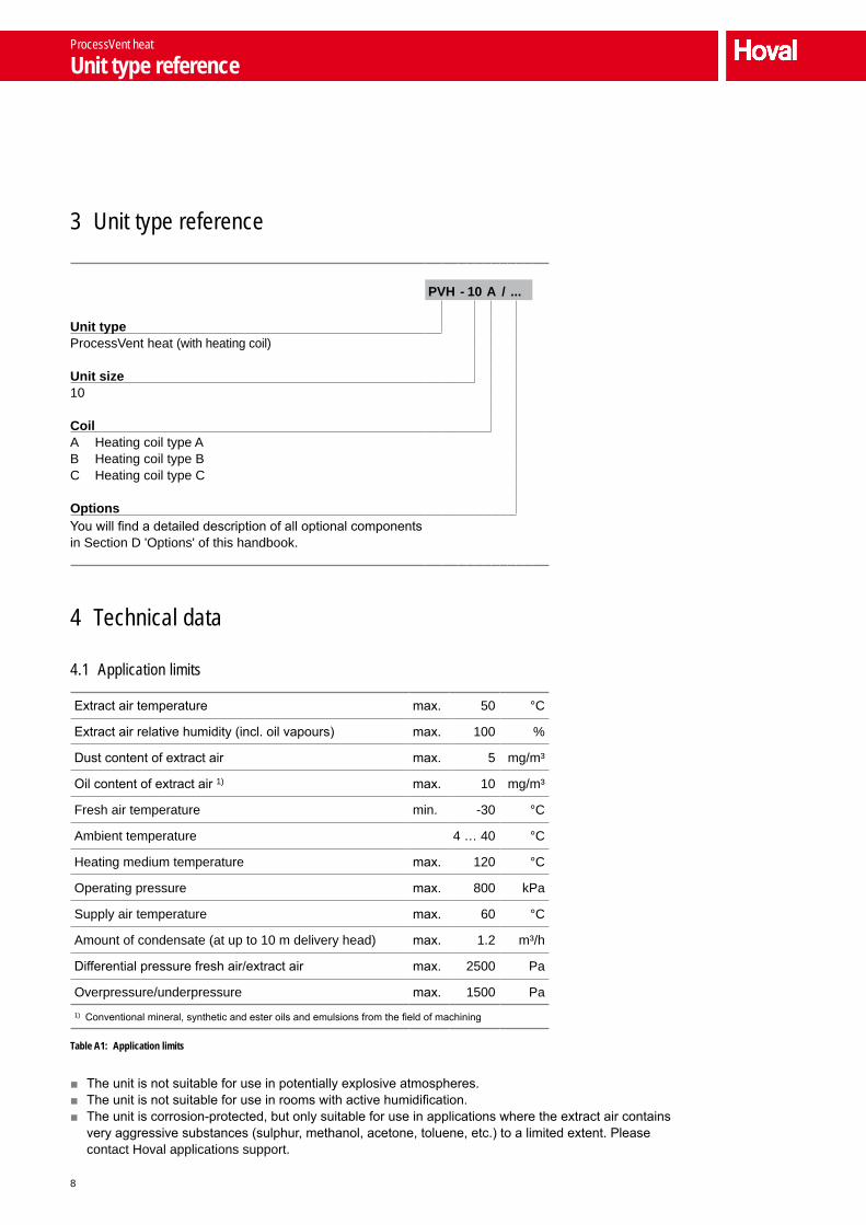
3 Unit type reference
PVH - 10 A / ...
Unit type ProcessVent heat (with heating coil)
Unit size10
CoilA Heating coil type AB Heating coil type BC Heating coil type C
OptionsYou will find a detailed description of all optional components in Section D 'Options' of this handbook.
4 Technical data
4.1 Application limits
Extract air temperature max. 50 °C
Extract air relative humidity (incl. oil vapours) max. 100 %
Dust content of extract air max. 5 mg/m³
Oil content of extract air 1) max. 10 mg/m³
Fresh air temperature min. -30 °C
Ambient temperature 4 … 40 °C
Heating medium temperature max. 120 °C
Operating pressure max. 800 kPa
Supply air temperature max. 60 °C
Amount of condensate (at up to 10 m delivery head) max. 1.2 m³/h
Differential pressure fresh air/extract air max. 2500 Pa
Overpressure/underpressure max. 1500 Pa1) Conventional mineral, synthetic and ester oils and emulsions from the field of machining
Table A1: Application limits
■ The unit is not suitable for use in potentially explosive atmospheres. ■ The unit is not suitable for use in rooms with active humidification. ■ The unit is corrosion-protected, but only suitable for use in applications where the extract air contains very aggressive substances (sulphur, methanol, acetone, toluene, etc.) to a limited extent. Please contact Hoval applications support.
ProcessVent heat
Unit type reference

9
A
B
C
D
E
F
G
4.2 Air flow rate, electrical connections
Air distribution Nominal air flow rate 1) 10 000 m³/h
Heat recovery Heat recovery efficiency, dry 61 %
Heat recovery efficiency, moist (max.) 95 %
Fan characteristics Supply voltage 3 x 400 V AC
Permitted voltage tolerance ±10 %
Frequency 50 Hz
Nominal power consumption 2 x 2.4 kW
Current consumption 2 x 3.9 A
Speed of rotation (nominal) 2400 rpm
Actuators Supply voltage 24 V DC
Control voltage 2…10 V DC
Filter Filter class F7
Factory setting, pressure monitor 250 Pa
Plate heat exchanger Factory setting, pressure monitor 250 Pa1) Control range 3000…12000 m³/h The air flow rate depends on the extract air volume flow. Operation at minimum air flow rate is only recommended in partial load operation or intermittent operation.
Table A2: Technical data
Unit type PVH-10A PVH-10B PVH-10C
Available pressure Pa 530 520 460
Table A3: Available fan pressure to compensate for external pressure drops (at nominal air flow rate)
4.3 Sound level
Position Duct connection, fresh air
Duct connection, supply air
Displacement flow diffuser
(option)
Sound power level dB(A) 71 66 75
Sound pressure level dB(A) – – 59 1)
1) Applies at a distance of 1 m from the unit, measuring surface sound pressure level according to DIN 45636
Table A4: Sound level
ProcessVent heat
Technical data

10
4.4 Heat output
The following applies for the data provided in the tables:
■ The data applies for the supply air temperatures specified. This requires the air to be blown into the room via a supply air duct and induction outlets. The supply air temperature must be restricted for units with displacement flow diffusers: – Reference value for heating operation: supply air max. 5 K warmer than
room airThe heat output also decreases accordingly. Please contact Hoval applications support for a project-specific design.
■ The total output of the unit is calculated from the heat output of the coil plus the output from energy recovery (Q + QER).
■ The data applies for the nominal air flow rate of 10 000 m³/h. The actual values are dependent on the actual air flow rate. The percentage change in these values for volume flows in the range 8 000…12 000 m³/h is shown in Diagram A1. For air flow rates under 8 000 m³/h, please contact Hoval applications support.
60%
80%
100%
120%
140%
8000 9000 10000 11000 12000
Air flow rate in m³/h
Water pressure drop
Heat output
Water flow rate
Supply air temperature
Diagram A1: Changes in output data depending on the air flow rate
ProcessVent heat
Technical data

11
A
B
C
D
E
F
G
Fresh air -15 °C/90% Heating medium 80/60 °C Heating medium 60/40 °CType tExt rhExt QER Q tS ΔpW mW Q tS ΔpW mW
°C % kW kW °C kPa l/h kW °C kPa l/hA 15 20 62 77 26 13 3 390 51 18 6 2 219
40 65 76 26 13 3 331 50 19 6 2 16360 70 75 27 12 3 273 49 20 6 2 10680 77 72 29 12 3 156 46 21 5 1 994
100 84 69 30 11 3 040 43 22 5 1 88220 20 73 73 28 12 3 214 47 20 6 2 050
40 77 72 29 12 3 156 46 21 5 1 99460 85 69 30 11 3 040 43 22 5 1 88280 93 65 32 10 2 867 40 25 4 1 715
100 101 63 33 10 2 753 37 26 4 1 60325 20 84 69 30 11 3 040 43 22 5 1 882
40 90 68 31 10 2 983 42 23 5 1 82660 99 63 33 9 2 753 37 26 4 1 60380 109 59 35 8 2 582 33 28 3 1 437
100 119 55 37 7 2 412 29 30 2 1 27130 20 95 64 33 9 2 810 38 25 4 1 659
40 104 62 34 9 2 696 36 27 3 1 54860 115 58 36 8 2 525 32 28 3 1 38280 126 53 39 6 2 299 27 31 2 1 161
100 137 49 41 6 2 131 23 33 1 994B 15 20 62 100 32 21 4 381 66 23 10 2 868
40 65 98 33 20 4 305 64 23 10 2 79460 70 97 33 20 4 229 63 24 9 2 72180 77 93 35 18 4 077 59 25 8 2 575
100 84 90 36 17 3 926 56 26 8 2 43020 20 73 95 34 19 4 153 61 24 9 2 648
40 77 93 35 18 4 077 59 25 8 2 57560 85 90 36 17 3 926 56 26 8 2 43080 93 85 38 15 3 701 51 28 6 2 213
100 101 81 39 14 3 553 48 29 6 2 07025 20 84 90 36 17 3 926 56 26 8 2 430
40 90 86 37 16 3 776 53 27 7 2 28560 99 81 39 14 3 553 48 29 6 2 07080 109 76 40 13 3 331 43 31 5 1 854
100 119 71 42 11 3 110 38 32 4 1 64030 20 95 83 38 15 3 627 49 28 6 2 141
40 104 79 39 14 3 478 46 30 5 1 99860 115 74 41 12 3 257 41 31 4 1 78380 126 68 43 10 2 965 35 33 3 1 497
100 137 63 45 9 2 747 30 35 2 1 282
ProcessVent heat
Technical data

12
C 15 20 62 167 51 30 7 302 112 36 15 4 87740 65 164 51 29 7 174 110 36 14 4 75560 70 161 52 28 7 047 107 36 14 4 63380 77 155 53 26 6 794 101 37 12 4 392
100 84 149 53 24 6 543 96 38 11 4 15120 20 73 158 52 27 6 920 104 37 13 4 512
40 77 155 53 26 6 794 101 37 12 4 39260 85 149 53 24 6 543 96 38 11 4 15180 93 141 54 22 6 170 87 38 9 3 794
100 101 135 55 20 5 924 82 39 8 3 55725 20 84 149 53 24 6 543 96 38 11 4 151
40 90 144 54 23 6 294 90 38 10 3 91360 99 135 55 20 5 924 82 39 8 3 55780 109 127 55 18 5 558 74 40 7 3 203
100 119 119 56 16 5 196 66 41 6 2 85030 20 95 138 54 21 6 047 85 39 9 3 675
40 104 132 55 19 5 802 79 39 8 3 43860 115 124 56 17 5 437 71 40 6 3 80580 126 113 57 15 4 957 60 41 5 2 615
100 137 105 58 13 4 602 52 42 4 2 236Legend: Type = Type of coil
tExt = Extract air temperaturerhExt = Extract air humidityQER = Energy recovery output
Q = Coil heat output tS = Supply air temperatureΔpW = Water pressure dropmW = Water flow rate
Table A5: Heat outputs of the ProcessVent heat at -15 °C
ProcessVent heat
Technical data

13
A
B
C
D
E
F
G
Fresh air -5 °C/90% Heating medium 80/60 °C Heating medium 60/40 °CType tExt rhExt QER Q tS ΔpW mW Q tS ΔpW mW
°C % kW kW °C kPa l/h kW °C kPa l/hA 15 20 41 73 28 12 3 214 47 20 6 2 050
40 42 72 29 12 3 156 46 21 5 1 99360 45 70 29 11 3 098 45 22 5 1 93780 50 69 30 11 3 040 43 22 5 1 881
100 57 67 31 10 2 924 41 24 4 1 77020 20 52 69 30 11 3 040 43 22 5 1 881
40 53 68 31 10 2 982 42 23 5 1 82660 58 67 31 10 2 924 41 24 4 1 77080 65 63 33 9 2 752 37 26 4 1 603
100 73 60 35 8 2 638 34 27 3 1 49225 20 62 64 33 9 2 810 38 25 4 1 659
40 65 63 33 9 2 752 37 26 4 1 60360 72 60 35 8 2 638 34 27 3 1 49280 81 58 36 8 2 525 32 28 4 1 382
100 91 54 38 7 2 355 28 30 2 1 21630 20 73 60 35 8 2 638 34 27 3 1 492
40 78 59 35 8 2 581 33 28 3 1 43760 86 55 37 7 2 412 29 30 2 1 27180 97 51 39 6 2 243 26 32 2 1 105
100 107 47 41 5 2 075 22 34 1 938B 15 20 41 95 34 19 4 152 61 24 9 2 648
40 42 93 35 18 4 076 59 25 8 2 57560 45 91 35 18 4 001 58 26 8 2 50280 50 90 36 17 3 926 56 26 8 2 430
100 57 86 37 16 3 776 53 27 7 2 28520 20 52 90 36 17 3 926 56 26 8 2 430
40 53 88 36 17 3 850 54 27 7 2 35760 58 86 37 16 3 776 53 27 7 2 28580 65 81 39 14 3 552 48 29 6 2 069
100 73 78 40 13 3 404 44 30 5 1 92625 20 62 83 38 15 3 626 49 28 6 2 141
40 65 81 39 14 3 552 48 29 6 2 06960 72 78 40 13 3 404 44 30 5 1 92680 81 74 41 12 3 186 41 31 4 1 783
100 91 69 43 11 3 037 36 33 3 1 56830 20 73 78 40 13 3 404 44 30 5 1 926
40 78 76 40 13 3 330 43 31 5 1 85460 86 71 42 11 3 110 38 32 4 1 64080 97 66 44 10 2 891 33 34 3 1 425
100 107 61 46 8 2 674 28 36 2 1 210
ProcessVent heat
Technical data

14
C 15 20 41 158 52 27 6 920 104 37 13 4 51240 42 155 52 26 6 749 101 37 12 4 39160 45 152 53 25 6 668 98 37 12 4 27180 50 149 53 24 6 543 96 38 11 4 151
100 57 144 54 23 6 294 90 38 10 3 91220 20 52 149 53 24 6 543 96 38 11 4 151
40 53 146 53 23 6 418 93 38 11 4 03260 58 144 54 23 6 294 90 38 10 3 91280 65 135 55 0 5 924 82 39 8 3 556
100 73 130 55 19 5 679 77 40 7 3 32025 20 62 138 54 21 6 047 85 39 9 3 675
40 65 135 53 20 5 924 82 39 8 3 55660 72 130 55 19 5 679 77 40 7 3 32080 81 124 56 17 5 437 71 40 6 3 085
100 91 116 57 15 5 076 63 41 5 2 73230 20 73 130 55 19 5 679 77 40 7 3 320
40 78 127 55 18 5 558 74 40 7 3 20260 86 119 56 16 5 196 66 41 6 2 85080 97 110 57 14 4 838 58 41 4 2 497
100 107 102 58 12 4 484 49 42 3 2 142Legend: Type = Type of coil
tExt = Extract air temperaturerhExt = Extract air humidityQER = Energy recovery output
Q = Coil heat output tS = Supply air temperatureΔpW = Water pressure dropmW = Water flow rate
Table A6: Heat outputs of the ProcessVent heat at -5 °C
ProcessVent heat
Technical data

15
A
B
C
D
E
F
G
4.5 Dimensions and weights
19051850 2000
1040
270
440
225
7471475187.5
180
180
140
47.5
288 340 288
∅ 63.5270
235
1246
1246
1040
235
235
500
1672
370
159
340
344
2465
4324
3059
990230 1515 255 = =
1745
Extract air duct connection
Fresh air duct connection
Exhaust air duct connection
Supply air duct connection, rear
Fresh air module
Return pipe feedthrough
Flow pipe feedthrough
Base unit
Fig. A4: Dimensional drawing (dimensions in mm)
ProcessVent heat
Technical data

16
Unit type PVH-10A PVH-10B PVH-10C
Components Base unit kg 1449 1449 1459
Fresh air module kg 240 240 240
Total kg 1689 1689 1699
Options Hydraulic assembly for diverting system kg 32 32 32
Table A7: Weights
ProcessVent heat
Technical data

17
A
B
C
D
E
F
G
5 Specification texts
ProcessVent heat
Compact unit for ventilating and heating production halls with heat recovery from process air, consisting of:
■ Fresh air module ■ Base unit with heat recovery in an oil-tight design, air
treatment and air introduction ■ Control system ■ Optional components
Fresh air module
Self-supporting, double-shell, foamed panel construction with insulation free of thermal bridges made of closed-cell polyurethane (PUR, building materials class B1 according to DIN 4102-1); equipped with jack rings for transport and installation on-site.
The fresh air module contains:
Fresh air/recirculation damper:Opposed dampers for switching between fresh air and recir-culation operation, including continuous actuator with safety function in the event of a power failure.
Fresh air filter:Designed as a compact filter of class F7, including differential pressure switch for filter monitoring.
Standard fanS
Supply air fans:Designed as maintenance-free, direct-drive radial fans with high-efficiency EC motors, backwards-curved, 3D contoured blades and a free-running rotating wheel made of a high-performance composite material; infinitely variable (2 pieces).
HigH-preSSure fanS
High-pressure fans:Designed as maintenance-free, direct-drive radial fans with high-efficiency EC motors, backwards-curved blades and a free-running rotating wheel made of aluminium; infinitely variable (2 pieces); in a high-pressure design to compensate for external pressure drops (e.g. through air ducts).
Duct connection, fresh air:Compensator with ventilation flange, fits on flange S30, for connection to the on-site fresh air duct.
Access door, fresh air:Large access opening for easily accessing the fresh air filter and the fans for maintenance purposes.
freSH air module, uprigHt
The fresh air module is intended for upright installation on the base unit and equipped with plug-in connections for easy electrical installation.
freSH air module, Horizontal
The fresh air module is intended for horizontal installation on the base unit and equipped with plug-in connections for easy electrical installation; including connection duct and transverse support made of sheet steel, welded, with high-quality anti-corrosion primer and paint finish.
paint finiSH aS deSired
The casing of the fresh air module is painted in the RAL colour of the customer's choice.
Base unit with heat recovery in an oil-tight design, air treat-ment and air introduction
Supporting framework construction made of steel sections, welded, with high-quality anti-corrosion primer and paint finish; bottom tray made of sheet steel, water and oil-tight, with high-quality anti-corrosion primer and paint finish; cover panels made of aluzinc sheet steel; equipped with jack rings and fork-lift openings for transport and installation on-site.
The base unit contains:
Cross-flow plate heat exchanger:In a water and oil-tight design to recover heat from process air. Exchanger package consists of epoxy-coated aluminium plates with pressed-in spacers. The plates have a keyed fold connection with one another, which multiplies the mate-rial strength for the air inlet and outlet. The corners of the exchanger package are stuck into the aluminium press-drawn hollow sections of the casing with a sealing compound to form a water and oil-tight seal. The side walls made of sheet steel with a high-quality anti-corrosion primer and paint finish are screwed flush with these corners and sealed so they are water and oil-tight. A bypass is positioned in the flow of supply air and sealed so it is air and oil-tight against the extract air side; leak test according to company standard. Opposed ER and bypass damper mounted on the casing to control the output of the cross-flow plate heat exchanger, including continuous actuator. Frost monitoring on the extract air side by means of differential pressure switch.
Condensate drip tray with drain:In a water and oil-tight design to remove oily condensate from the cross-flow plate heat exchanger, with high-quality anti-corrosion primer and paint finish.
ProcessVent heat
Specification texts

18
Extract air and exhaust air duct section:Water and oil-tight welded construction made of steel for conveying air containing oil, insulated with closed-cell Poly-cell (building materials class B2 according to DIN 4102-1), equipped with media-resistant compensators (2 pieces) with DIN flanged connecting pieces for connection to the on-site extract air and exhaust air duct.
Fresh air duct section:Transition between the fresh air module and the cross-flow plate heat exchanger, made of aluzinc sheet steel, insu-lated with closed-cell Polycell (building materials class B2 according to DIN 4102-1).
Supply air duct section:Transition between the cross-flow plate heat exchanger and the air introduction section, made of aluzinc sheet steel.
Air treatment unit, heating:Casing made of aluzinc sheet steel, includes the heating coil made of copper tubes and aluminium fins and the frost controller.
Supply air duct connection, rear
Air outlet box with supply air duct section:Connection to the on-site air distribution system, equipped with a compensator with ventilation flange, fits on flange S30, for connection to the on-site supply air duct (on the rear of the unit).
Supply air duct connection, left
Air outlet box with supply air duct section:Connection to the on-site air distribution system, equipped with a compensator with ventilation flange, fits on flange S30, for connection to the on-site supply air duct (on the left of the unit).
diSplacement flow diffuSer
Displacement flow diffuser:Cover panels towards the bottom of the base unit designed as a displacement flow diffuser for introducing the supply air into the occupied area in a low-pulse, duct-free manner; consisting of:
■ Outlet panel designed as a perforated sheet ■ Fabric mat for air distribution ■ Spring rods for attaching the fabric mat
Access openings: ■ Access door, exhaust air: large access opening for easily accessing the cross-flow plate heat exchanger for mainte-nance purposes; panel designed with a water and oil-tight closing system
■ Access door, extract air: large access opening for easily accessing the condensate drip tray with drain for mainte-nance purposes; panel designed with a water and oil-tight closing system
■ Access panel, supply air: large revision openings on all sides (4 pieces) with panels for easily accessing other components for maintenance purposes (depending on equipment: ER and bypass damper, coil, hydraulic connections, return pump station, condensate drain)
Control box with control module as part of the Hoval ProcessNet control system:
■ Control box made of sheet steel, powder-coated with textured paint in light grey (RAL 7035), integrated flush with the framework construction
■ Control module fully prewired with all I/O components: – Supply air fans – Actuator, fresh air/recirculation damper – Actuator, ER/bypass damper – Temperature sensor, mixed air – Temperature sensor, supply air – Frost monitoring, plate heat exchanger – Frost controller – Differential pressure switch, fresh air filter – Volume flow monitoring, supply air fans – Optional components as required
■ Room and fresh air sensors supplied with plug, for on-site installation at a suitable location and wiring to the socket on the outside of the unit
■ Mains power terminals ■ Fuse for the electronics ■ Transformer for control module and actuators ■ Cable glands designed as cable feedthrough plates
Standard paint finiSH
The following components of the base unit are painted in Hoval red (RAL 3000):
■ Framework construction ■ Bottom tray ■ Side walls of the plate heat exchanger ■ Condensate drip tray ■ Extract air and exhaust air duct section
paint finiSH aS deSired
The following components of the base unit are painted in the RAL colour of the customer's choice:
■ Framework construction ■ Bottom tray ■ Side walls of the plate heat exchanger ■ Condensate drip tray ■ Extract air and exhaust air duct section
ProcessVent heat
Specification texts

19
A
B
C
D
E
F
G
Options for the unit
Hydraulic assembly for diverting system:Prefabricated assembly for the hydraulic diverting system, installed in the unit, consisting of:
■ 3-way control ball valve designed with a continuous actuator
■ Line balancing valve STAD with integrated drain valve ■ Ball valve with extended spindle ■ Connecting pipes with bypass designed as galvanised
malleable cast-iron threaded pipes ■ Screw joints for easy connection to the on-site distributor
circuit
Assembly fully insulated with closed-cell insulating mate-rial to prevent energy loss and surface condensation on the assembly's components; 3-way control ball valve with plug-in connection fully prewired on the control box for easy mainte-nance; components adapted to the relevant heating/cooling coil and the ProcessNet control system
The output is regulated via the 3-way control ball valve: the medium is routed through the coil or the bypass. The bypass is dimensioned such that it corresponds to the resistance of the coil. This ensures that the pressure in the load circuit remains constant.
The line balancing valve in the flow coordinates the total resistance of the load with the distribution circuit. In addition, the line balancing valve can also be used to shut the line off completely.
Technical data, line balancing valve: – Max. pressure 800 kPa at 120°
Technical data, control ball valve: – Supply voltage: 24 V DC – Control voltage 0…10 V DC – Operating range: 2…10 V DC – Position response: 2…10 V DC – Actuator run time: 4 s/90° – Casing material: nickel-plated hot-pressed brass – Closing element material: stainless steel
Return pump station water:Pump station for returning condensate for recycling or disposal; suitable for water-emulsion mixtures; installed in the unit, fully electrically prewired; consisting of:
■ Hosing from condensate drains to pump receiver ■ Pump receiver ■ Submersible pump ■ Check valve ■ Level probe
Technical data: – Pump output: 25 l/min – Delivery head: 8 m – Motor output: 0.14 kW – Speed of rotation: 2 700 rpm – Voltage: 3 x 400 V AC – Frequency: 50 Hz – Protection rating: IP 55 – Pump material: PPS – Pump shaft material: 1.4104 – Pump receiver material: SJ235R – Piping material: Threaded pipe according to DIN 2440, seamlessly galvanised, including fittings; PVC fabric hoses
– Nominal diameter of the connections: ¾ "
Return pump station oil:Pump station for returning condensate for recycling or disposal; suitable for oily condensate from the plate heat exchanger (with an upstream oil separator); installed in the unit, fully electrically prewired; consisting of:
■ Hosing from condensate drains to pump receiver ■ Pump receiver ■ Submersible pump ■ Check valve ■ Level probe
Technical data: – Pump output: 25 l/min – Delivery head: 8 m – Motor output: 0.14 kW – Speed of rotation: 2 700 rpm – Voltage: 3 x 400 V AC – Frequency: 50 Hz – Protection rating: IP 55 – Pump material: PPS – Pump shaft material: 1.4104 – Pump receiver material: SJ235R – Piping material: Threaded pipe according to DIN 2440, seamlessly galvanised, including fittings; PVC fabric hoses
– Nominal diameter of the connections: ¾ "
ProcessVent heat
Specification texts

20
Control systems
Control system for the energy-optimised operation of Hoval ProcessVent plants, designed as a decentralised I/O system, with the following main features:
■ Control module integrated in every unit, for autonomous and individual regulation of the units, allowing for precise adaptation to the operating conditions
■ Master-slave function for forming zones of several units being operated under the same conditions (e.g. same room temperature set values, same operating times)
■ Operating mode switching via – Time programme, holiday and vacation calendar – Specification of a building management system
■ The following control functions are performed by the control module: – Control of energy recovery depending on the tempera-
ture conditions – Control of supply air temperature via fixed value control
or room air/supply air cascade control – Fixed value control of volume flow – Soft starting to protect the unit when switching over to
operating states with fresh air – Defrosting if plate heat exchanger is iced up using the flow of extract air during plant operation
– Messages relating to the plant's heat or cool demand for external heating and refrigerating systems
– Fire control: connection for an external signal to shut the plant down in the event of a fire
– Signal for controlling external extract air systems when the plant is in an operating state where only fresh air is supplied to the hall and no extract air is removed from it (supply air/night cooling summer operating mode)
■ Simple connection of the units to a building management system via an interface integrated in the control module by means of the Profinet protocol in order to exchange the following data: – Current operating mode – Temperature control strategy – Temperature set values – Temperature actual values – Damper positions – Alarms – Energy meter (energy monitoring option)
■ Alarm handling via control module by means of 1 collec-tive alarm routed to terminal and transmission of alarm signals for visualisation
■ Running time meter for each unit ■ Back-up and restore function for easy saving of user
settings and loading of factory settings ■ Electrical documentation supplied in the control box
Options for control systems
Connection via Ethernet:Electrical components and software interface for exchanging signals between Hoval ProcessVent and Hoval ProcessClean extract air purification plants via Ethernet; electrical components installed and fully prewired in the ProcessVent control box; visualisation on the ProcessClean extract air purification plant.
Connection via Profinet:Electrical components and software interface for exchanging signals between Hoval ProcessVent and Hoval ProcessClean extract air purification plants via Profinet; electrical components installed and fully prewired in the ProcessVent control box; visualisation on the ProcessClean extract air purification plant.
Connection via Profibus DP coupler:Electrical components and software interface for exchanging signals between Hoval ProcessVent and Hoval ProcessClean extract air purification plants via a Profibus DP coupler; electrical components installed and fully prewired in the ProcessVent control box; visualisation on the ProcessClean extract air purification plant.
Connection via external signals:Electrical components and software interface for connecting one or more (maximum 4) non-Hoval extract air purification plants to the Hoval ProcessNet control system; visualisation via building management system or touchpanel on the unit.Connection via digital inputs and outputs:
■ Digital inputs, operating message, extract air purification plant 1 – 4
■ Digital input, emergency stop, extract air purification plant ■ Digital input, collective alarm ■ Digital outputs, enable, extract air purification plant 1 – 4
Room temperature averaging:3 additional room air sensors supplied for averaging; for on-site installation at a suitable location and wiring to the socket on the outside of the unit
Energy monitoring:Calculation of the energy saved with the cross-flow plate heat exchanger and display on the operator terminal; addi-tional temperature sensor and analogue input installed in the unit; fully prewired.
Design for injection system:Components for controlling and protecting a heating/cooling pump integrated in the control box; digital output routed to terminals in the control box.
Requirements for the pump in the load circuit: – Power supply: 230 V AC – Power consumption: max. 1 kW
ProcessVent heat
Specification texts

21
A
B
C
D
E
F
G
– Current consumption: max. 4 A – Input signal for activation of control of pump ON – Output signal for pump alarm
Control of supply air damper:Control of an on-site supply air damper depending on the operating state of the compact unit; consisting of:
■ Digital output routed to terminals in the control box (0...10 V DC)
■ Output terminals in the control box for supplying power to the actuator (24 V DC)
■ Analogue input for position return signal from the actuator (2...10 V DC)
Control of exhaust air damper:Control of an on-site exhaust air damper depending on the operating state of the extract air purification plant; consisting of:
■ Digital output routed to terminals in the control box (0...10 V DC)
■ Output terminals in the control box for supplying power to the actuator (24 V DC)
■ Analogue input for position return signal from the actuator (2...10 V DC)
Touchpanel on the unit:Preprogrammed plug & play operator terminal with graphical user interface for using the Hoval ProcessVent in plants with non-Hoval extract air purification plants:
■ Touchpanel with colour display installed in the doors of the control box
■ Facilitates monitoring and programming of Hoval ProcessNet (operating modes, temperature values, time programme, calendar, alarm handling, control parameters)
Power supply:Power supply for Hoval ProcessVent if this is installed in conjunction with non-Hoval extract air purification plants. The power supply contains the following components:
■ Mains power terminals ■ Circuit breaker to protect the supply air fans of the Hoval
ProcessVent ■ 3-pin safety relay installed in the control box doors ■ In the design for injection system: circuit breaker to protect
the heating pump
Technical data
General:Nominal air quantity: ______________m³/hExternal available pressure: _______________ Pa
Dimensions (length x width x height):Base unit: 2000 x 1850 x 2904 mmFresh air module: 1631 x 700 x 1430 mmTotal: 2000 x 1850 x 4334 mm
Weight:Base unit: _______________ kgFresh air module: _______________ kgTotal: _______________ kg
Fans:Supply voltage: 3 x 400 V AC/50 HzPower consumption: ______________ kWCurrent consumption: ________________ ASpeed of rotation (nominal): ______________ rpmProtection rating: IP 54
Sound data:Sound power level:– Duct connection, fresh air: _____________dB(A)– Duct connection, supply air: _____________dB(A)– Displacement flow diffuser: _____________dB(A)Sound pressure level at 1 m distance from the unit: _____________dB(A)
Heat recovery:Fresh air temperature: _______________ °CFresh air relative humidity: ________________%Extract air temperature: _______________ °CExtract air relative humidity: _______________ %
Heat recovery efficiency, dry: ________________%Heat recovery efficiency, moist: ________________%Pressure drop: _______________ Pa
Technical data, heating coil:Heat output: _______________kWFlow/return: _______________ °CSupply air temperature: _______________ °CAt air inlet temperature: _______________ °COperating pressure: ______________ kPa
ProcessVent heat
Specification texts

22

23
ProcessVent cool PVCCompact unit for ventilating, heating and cooling production halls with heat recovery from process air
B
1 Use ____________________________________ 24
2 Construction and operation__________________ 24
3 Unit type reference ________________________ 28
4 Technical data ____________________________ 28
5 Specification texts _________________________ 37
ProcessVent cool
Contents

24
1 Use
1.1 Intended use
The ProcessVent unit is used to recover heat from process air and supply fresh air to halls containing enclosed machine tools or welding plants. The extract air from the extract air purification plant flows through a plate heat exchanger in an oil-tight design and is routed to the outside via a duct; the heat it contains is transferred to the supply air. Additionally equipped with a heating/cooling coil for post-heating or cooling of the supply air.
Intended use also includes compliance with the installation, commissioning, operating and servicing conditions (operating manual).Any use above and beyond this is deemed improper. The manufacturer can accept no liability for damage resulting from improper use.
1.2 User group
The unit may only be installed, operated and serviced by authorised and trained specialist personnel who are familiar with the unit and aware of the risks involved.The operating manual is intended for English-speaking oper-ating engineers and technicians and for specialist building services, heating and ventilation technology personnel.
2 Construction and operation
The ProcessVent unit forms one overall system with the extract air purification plant: The extract air purification plant draws off soiled air from machine tools or welding plants by means of a fan. It purifies this process air and transports it onwards through the extract air duct to the ProcessVent unit.
The ProcessVent unit fulfils the following functions: ■ Heating with connection to hot water supply ■ Cooling with connection to chilled water system ■ Fresh air supply ■ Extract air removal (with air conveyance via the extract air purification plant)
■ Recovery of heat from the process air ■ Recirculation operation ■ Air filtration
Machine tool
Extract air purification plant
ProcessVent
Fig. B1: The ProcessVent unit forms one overall system with the extract air purifica-tion plant.
ProcessVent cool
Use

25
A
B
C
D
E
F
G
2.1 Construction
Heating/cooling coil with condensate separator
Condensate connection, heating/cooling coil
Condensate connection, plate heat exchanger
Access door, extract air
Duct connection, extract air
Supply air fans
Fresh air filter (class F7) with filter monitoring
Duct connection, fresh air
Access door, fresh air
Control box
Plate heat exchanger with frost monitoring
ER and bypass damper with continuous actuator
Duct connection, exhaust air
Recirculation air inlet
Fresh air/recirculation damper with continuous actuator
Access door, exhaust air
Access panels, supply air (on all sides)
Supply air duct connection, rear
Fig. B2: Unit construction
ProcessVent cool
Construction and operation

26
2.2 Operational diagram
Exhaust air
Temperature sensor, energy monitoring (optional)
Heating/cooling coil with frost controller and condensate separator
Supply air sensor
Supply air
Recirculation
Plate heat exchanger with differential pressure switch
ER/bypass damper with actuator
Mixed air sensor
Fresh air
Fresh air/recirculation damper with actuator
Fresh air filter with differential pressure switch
Supply air fans with volume flow monitoring
Condensate connection
Extract air sensor
Extract air
Fresh air sensor
Room air sensor
Fig. B3: Operational diagram
ProcessVent cool
Construction and operation

27
A
B
C
D
E
F
G
2.3 Operating modes
The unit has the following operating modes: ■ Ventilation ■ Supply air ■ Recirculation
■ Recirculation night ■ Night cooling summer ■ Off
The ProcessNet control system or the higher-level building management system controls the overall plant automatically. The operating mode of the ProcessVent units depends on:
■ the time programme ■ the operating states of the machines from which the
process air is to be drawn off
The following applies: When the machines are in operation, the ProcessVent unit always works in 'Ventilation' mode. The operating mode defined in the time programme is overridden.You can also control the operating mode of the ProcessVent unit manually and thus independently of the overall plant (e.g. for maintenance activities).You will find a detailed description of the ProcessNet control system in Section F 'Control systems' of this handbook.
Code ProcessVent operating mode Description
VE VentilationThe unit blows fresh air into the room. The fresh air quantity is constant; it is dependent on the extract air volume flow. The extract air from the extract air purification plant flows through the plate heat exchanger into the open air.The room temperature set value day is active. Heating/cooling and energy recovery are regulated depending on the heat/cool demand and the temperature conditions.
Supply air fan.....................On 1)
Energy recovery ................0 – 100%Fresh air damper ...............OpenRecirculation damper.........ClosedHeating/cooling ..................0 - 100%
1) Nominal volume flow as per setting in the control system (adjusted to the extract air volume flow)
SA Supply airThe unit blows fresh air into the room. The fresh air quantity is constant. Room air flows into the open via open doors and windows or is drawn off via an external system.The room temperature set value day is active. Heating/cooling is regu-lated depending on the heat/cool demand.
Supply air fan.....................On 1)
Energy recovery ................0%Fresh air damper ...............OpenRecirculation damper.........ClosedHeating/cooling ..................0 - 100%
1) Nominal volume flow as per setting in the control system
REC RecirculationIn the case of heat/cool demand, the unit draws in room air via the recirculation damper, heats or cools it and blows it back into the room.The room temperature set value day is active. The recirculation volume flow depends on the heat/cool demand.
Supply air fan.....................0 - 100% 1)
Energy recovery ................0%Fresh air damper ...............ClosedRecirculation damper.........OpenHeating/cooling ..................On 1)
1) Dependent on heat/cool demandRECN Recirculation nightLike REC, but with room temperature set value night
NCS Night cooling summerOn/off operation with room temperature set value night:
■ If current temperatures permit, the unit blows cool fresh air into the room and thus uses it for free cooling.
■ If current temperatures do not permit free cooling, the unit switches off.
Supply air fan.....................On 1) 2)
Energy recovery ................0%Fresh air damper ...............Open 2)
Recirculation damper.........Closed 2)
Heating/cooling ..................Off
1) Volume flow set in the control system2) Depending on temperature conditions
OFF OffThe unit is switched off. The frost protection switch remains active.
Supply air fan.....................OffEnergy recovery ................0%Fresh air damper ...............ClosedRecirculation damper.........OpenHeating/cooling ..................Off
ProcessVent cool
Construction and operation

28
3 Unit type reference
PVC - 10 C / ...
Unit type ProcessVent cool (with heating/cooling coil)
Unit size10
CoilC Heating/cooling coil type CD Heating/cooling coil type D
OptionsYou will find a detailed description of all optional components in Section D 'Options' of this handbook.
4 Technical data
4.1 Application limits
Extract air temperature max. 50 °C
Extract air relative humidity (incl. oil vapours) max. 100 %
Dust content of extract air max. 5 mg/m³
Oil content of extract air 1) max. 10 mg/m³
Fresh air temperature min. -30 °C
Ambient temperature 4 … 40 °C
Heating medium temperature max. 120 °C
Operating pressure max. 800 kPa
Supply air temperature max. 60 °C
Amount of condensate (at up to 10 m delivery head) max. 1.2 m³/h
Differential pressure fresh air/extract air max. 2500 Pa
Overpressure/underpressure max. 1500 Pa1) Conventional mineral, synthetic and ester oils and emulsions from the field of machining
Table B1: Application limits
■ The unit is not suitable for use in potentially explosive atmospheres. ■ The unit is not suitable for use in rooms with active humidification. ■ The unit is corrosion-protected, but only suitable for use in applications where the extract air contains very aggressive substances (sulphur, methanol, acetone, toluene, etc.) to a limited extent. Please contact Hoval applications support.
ProcessVent cool
Unit type reference

29
A
B
C
D
E
F
G
4.2 Air flow rate, electrical connections
Air distribution Nominal air flow rate 1) 10 000 m³/h
Heat recovery Heat recovery efficiency, dry 61 %
Heat recovery efficiency, moist (max.) 95 %
Fan characteristics Supply voltage 3 x 400 V AC
Permitted voltage tolerance ±10 %
Frequency 50 Hz
Nominal power consumption 2 x 2.4 kW
Current consumption 2 x 3.9 A
Speed of rotation (nominal) 2400 rpm
Actuators Supply voltage 24 V DC
Control voltage 2…10 V DC
Filter Filter class F7
Factory setting, pressure monitor 250 Pa
Plate heat exchanger Factory setting, pressure monitor 250 Pa1) Control range 3000…12000 m³/h The air flow rate depends on the extract air volume flow. Operation at minimum air flow rate is only recommended in partial load operation or intermittent operation.
Table B2: Technical data
Unit type PVC-10C PVC-10D
Available pressure Pa 420 320
Table B3: Available fan pressure to compensate for external pressure drops (at nominal air flow rate)
4.3 Sound level
Position Duct connection, fresh air
Duct connection, supply air
Displacement flow diffuser
(option)
Sound power level dB(A) 71 66 75
Sound pressure level dB(A) – – 59 1)
1) Applies at a distance of 1 m from the unit, measuring surface sound pressure level according to DIN 45636
Table B4: Sound level
ProcessVent cool
Technical data

30
4.4 Heat output
The following applies for the data provided in the tables:
■ The data applies for the supply air temperatures specified. This requires the air to be blown into the room via a supply air duct and induction outlets. The supply air temperature must be restricted for units with displacement flow diffusers: – Reference value for heating operation: supply air max. 5 K warmer than
room air – Reference value for cooling operation: supply air max. 6 K colder than room
airThe heat output/cooling capacity also decreases accordingly. Please contact Hoval applications support for a project-specific design.
■ The total output of the unit is calculated from the heat output of the coil plus the output from energy recovery (Q + QER).
■ The data applies for the nominal air flow rate of 10 000 m³/h. The actual values are dependent on the actual air flow rate. The percentage change in these values for volume flows in the range 8 000…12 000 m³/h is shown in Diagram B1. For air flow rates under 8 000 m³/h, please contact Hoval applications support.
60%
80%
100%
120%
140%
8000 9000 10000 11000 12000
Air flow rate in m³/h
Water pressure drop
Heat output
Water flow rate
Supply air temperature
Diagram B1: Changes in output data depending on the air flow rate
ProcessVent cool
Technical data

31
A
B
C
D
E
F
G
Fresh air -15 °C/90% Heating medium 80/60 °C Heating medium 60/40 °CType tExt rhExt QER Q tS ΔpW mW Q tS ΔpW mW
°C % kW kW °C kPa l/h kW °C kPa l/hC 15 20 62 167 51 30 7 302 112 36 15 4 877
40 65 164 51 29 7 174 110 36 14 4 75560 70 161 52 28 7 047 107 36 14 4 63380 77 155 53 26 6 794 101 37 12 4 392
100 84 149 53 24 6 543 96 38 11 4 15120 20 73 158 52 27 6 920 104 37 13 4 512
40 77 155 53 26 6 794 101 37 12 4 39260 85 149 53 24 6 543 96 38 11 4 15180 93 141 54 22 6 170 87 38 9 3 794
100 101 135 55 20 5 924 82 39 8 3 55725 20 84 149 53 24 6 543 96 38 11 4 151
40 90 144 54 23 6 294 90 38 10 3 91360 99 135 55 20 5 924 82 39 8 3 55780 109 127 55 18 5 558 74 40 7 3 203
100 119 119 56 16 5 196 66 41 6 2 85030 20 95 138 54 21 6 047 85 39 9 3 675
40 104 132 55 19 5 802 79 39 8 3 43860 115 124 56 17 5 437 71 40 6 3 80580 126 113 57 15 4 957 60 41 5 2 615
100 137 105 58 13 4 602 52 42 4 2 236D 15 20 62 199 60 26 8 737 138 43 14 5 996
40 65 199 60 26 8 737 138 43 14 5 99660 70 191 60 24 8 521 131 43 13 5 70480 77 182 60 22 7 998 125 44 12 5 414
100 84 174 60 20 7 636 118 44 11 5 12620 20 73 187 60 23 8 181 128 43 12 5 558
40 77 182 60 22 7 998 125 44 12 5 41560 85 174 60 20 7 636 118 44 11 5 12680 93 162 60 18 7 103 108 44 9 4 698
100 101 154 60 16 6 753 102 45 8 4 41425 20 84 174 60 20 7 636 118 44 11 5 126
40 90 166 60 19 7 279 112 44 10 4 84060 99 154 60 16 6 753 102 45 8 4 41480 109 142 60 14 6 238 92 45 7 3 991
100 119 131 60 12 5 733 82 46 5 3 57030 20 95 158 60 17 6 927 105 45 9 4 556
40 104 150 60 16 6 580 99 45 8 4 27360 115 138 60 14 6 069 89 45 6 3 85180 126 123 60 11 5 402 76 46 5 3 290
100 137 112 60 9 4 915 66 46 4 2 867Legend: Type = Type of coil
tExt = Extract air temperaturerhExt = Extract air humidityQER = Energy recovery output
Q = Coil heat outputtS = Supply air temperatureΔpW = Water pressure dropmW = Water flow rate
Table B5: Heat outputs of the ProcessVent cool at -15 °C
ProcessVent cool
Technical data

32
Fresh air -5 °C/90% Heating medium 80/60 °C Heating medium 60/40 °CType tExt rhExt QER Q tS ΔpW mW Q tS ΔpW mW
°C % kW kW °C kPa l/h kW °C kPa l/hC 15 20 41 158 52 27 6 920 104 37 13 4 512
40 42 155 52 26 6 749 101 37 12 4 39160 45 152 53 25 6 668 98 37 12 4 27180 50 149 53 24 6 543 96 38 11 4 151
100 57 144 54 23 6 294 90 38 10 3 91220 20 52 149 53 24 6 543 96 38 11 4 151
40 53 146 53 23 6 418 93 38 11 4 03260 58 144 54 23 6 294 90 38 10 3 91280 65 135 55 0 5 924 82 39 8 3 556
100 73 130 55 19 5 679 77 40 7 3 32025 20 62 138 54 21 6 047 85 39 9 3 675
40 65 135 53 20 5 924 82 39 8 3 55660 72 130 55 19 5 679 77 40 7 3 32080 81 124 56 17 5 437 71 40 6 3 085
100 91 116 57 15 5 076 63 41 5 2 73230 20 73 130 55 19 5 679 77 40 7 3 320
40 78 127 55 18 5 558 74 40 7 3 20260 86 119 56 16 5 196 66 41 6 2 85080 97 110 57 14 4 838 58 41 4 2 497
100 107 102 58 12 4 484 49 42 3 2 142D 15 20 41 187 60 23 8 183 128 43 12 5 558
40 42 183 60 22 8 000 125 44 12 5 41460 45 183 60 22 8 000 125 44 12 5 41480 50 174 60 20 7 638 118 44 11 5 126
100 57 166 60 19 7 281 112 44 10 4 84020 20 52 174 60 20 7 638 118 44 11 5 126
40 53 170 60 20 7 459 115 44 10 4 98360 58 166 60 19 7 281 112 44 10 4 84080 65 154 60 16 6 755 102 45 8 4 414
100 73 146 60 15 6 410 95 45 7 4 13225 20 62 158 60 17 6 929 105 45 9 4 556
40 65 154 60 16 6 755 102 45 8 4 41460 72 146 60 15 6 410 90 45 7 4 13280 81 139 60 14 6 070 89 45 6 3 851
100 91 127 60 12 5 569 79 46 5 3 43030 20 73 146 60 15 6 410 95 45 7 4 132
40 78 142 60 14 6 240 92 45 7 3 99160 86 131 60 12 5 735 82 46 5 3 57080 97 120 60 10 5 240 73 46 4 3 149
100 107 109 60 9 4 756 63 46 3 2 725Legend: Type = Type of coil
tExt = Extract air temperaturerhExt = Extract air humidityQER = Energy recovery output
Q = Coil heat output tS = Supply air temperatureΔpW = Water pressure dropmW = Water flow rate
Table B6: Heat outputs of the ProcessVent cool at -5 °C
ProcessVent cool
Technical data

33
A
B
C
D
E
F
G
4.5 Cooling capacity
The following applies for the data provided in the tables:
■ The total sensitive cooling capacity of the unit is calcu-lated from the sensitive cooling capacity of the coil plus the output from energy recovery (Qsen + QER).
■ The data applies for the nominal air flow rate of 10 000 m³/h. The actual values are dependent on the actual air flow rate. The percentage change in these values for volume flows in the range 8 000…12 000 m³/h is shown in Diagram B2. For air flow rates under 8 000 m³/h, please contact Hoval applications support.
Cooling capacity with upstream dry filter or oil/emulsion mist separator
Cooling medium 6/12 °C Cooling medium 8/14 °CType tFre rhFre Qsen Qtot tS ΔpW mW mC Qsen Qtot tS ΔpW mW mC
°C % kW kW °C kPa l/h l/h kW kW °C kPa l/h l/hC 28 40 42 46 15 30 6 527 6 38 39 17 22 5 547 2
60 38 67 16 60 9 531 41 34 56 18 43 8 018 3230 40 46 54 16 41 7 707 12 42 46 17 30 6 534 6
60 42 79 17 82 11 345 54 38 69 18 63 9 832 4432 40 49 63 17 54 8 990 20 46 54 18 40 7 718 12
60 45 93 18 110 13 269 68 41 82 19 87 11 744 58D 28 40 50 58 13 30 8 301 12 45 49 14 22 6 972 5
60 47 85 14 61 12 236 55 42 73 15 45 10 402 4430 40 54 69 13 41 9 855 21 50 58 15 30 8 319 12
60 51 101 14 83 14 479 71 47 88 16 64 12 650 6032 40 59 81 14 55 11 544 32 54 69 15 41 9 843 21
60 56 118 15 109 16 850 88 51 105 16 88 15 031 77Legend: Type = Type of coil
tFre = Fresh air temperaturerhFre = Fresh air humidityQsen = Sensitive cooling capacity of the coilQtot = Total cooling capacity
tS = Supply air temperatureΔpW = Water pressure dropmW = Water flow ratemC = Amount of condensate
Refers to: Extract air temperature ≥ fresh air temperature (→ without energy recovery)
Table B7: Cooling capacities of the ProcessVent cool with upstream dry filter or oil/emulsion mist separator
60%
80%
100%
120%
140%
8000 9000 10000 11000 12000
Air flow rate in m³/h
Water pressure drop
Cooling capacity, sensitive
Cooling capacity, total
Water flow rate
Supply air temperature
Diagram B2: Changes in output data depending on the air flow rate
ProcessVent cool
Technical data

34
Cooling capacity with upstream wet separator
Cooling medium 6/12 °C Cooling medium 8/14 °CType tExt tFre rhFre QER Qsen Qtot tS ΔpW mW mC Qsen Qtot tS ΔpW mW mC
°C °C % kW kW kW °C kPa l/h l/h kW kW °C kPa l/h l/hC 15 28 40 27 22 27 14 12 3 854 8 18 19 15 6 2 776 2
60 28 21 53 15 40 7 623 46 17 43 16 26 6 098 3730 40 31 23 35 14 19 5 042 18 19 24 15 9 3 483 8
60 33 23 60 15 50 8 582 53 19 49 16 34 7 060 4432 40 35 25 44 15 29 6 363 28 21 34 16 17 4 827 19
60 37 24 70 16 65 9 953 66 20 59 17 47 8 433 5520 28 40 17 29 34 14 18 4 872 7 26 27 15 11 3 847 2
60 17 26 57 15 45 8 144 44 22 46 17 31 6 623 3530 40 21 30 41 15 25 5 890 25 26 30 16 14 4 350 6
60 21 27 68 16 63 9 765 59 23 58 17 46 8 247 4932 40 25 32 51 15 37 7 276 27 28 40 17 24 5 750 18
60 25 28 79 17 82 11 340 73 25 69 18 63 9 820 6325 28 40 6 37 41 15 25 5 854 6 33 34 16 17 4 871 2
60 6 33 62 16 53 8 894 41 29 52 17 37 7 378 3230 40 10 38 47 16 31 6 680 13 34 36 17 20 5 153 4
60 11 34 74 17 73 10 611 57 31 64 18 55 9 095 4732 40 15 39 56 16 43 7 972 24 36 47 17 31 6 664 16
60 15 35 87 17 98 12 441 73 32 76 18 76 10 914 64D 15 28 40 27 27 36 12 13 5 118 13 22 26 13 7 3 665 5
60 28 27 69 13 42 9 896 60 22 56 14 28 8 033 4930 40 31 29 47 12 20 6 683 26 23 33 14 11 4 754 14
60 33 30 77 13 51 11 084 68 25 64 15 36 9 231 5732 40 35 31 58 13 30 8 326 39 26 45 14 19 6 444 28
60 37 30 81 13 55 11 539 74 24 68 15 40 9 689 6220 28 40 17 36 44 12 19 6 336 13 31 35 14 12 4 984 5
60 17 33 74 99 46 10 536 58 28 61 15 32 8 682 4730 40 21 37 54 13 27 7 730 24 32 41 14 16 5 841 13
60 21 35 88 14 64 12 547 75 30 75 12 47 10 703 6432 40 25 40 66 13 38 9 449 38 34 53 15 25 7 591 27
60 25 37 101 14 83 14 502 93 32 88 15 64 12 661 8125 28 40 6 44 52 13 25 7 509 12 40 43 14 18 6 198 5
60 6 41 80 14 54 11 454 55 36 67 15 39 9 612 4430 40 10 46 61 13 33 8 702 22 41 48 15 21 6 840 11
60 11 43 95 14 74 13 582 74 38 82 15 56 11 740 6332 40 15 48 72 13 45 10 301 35 43 60 15 32 8 586 25
60 15 45 111 14 98 15 846 94 40 98 16 77 14 018 83Legend: Type = Type of coil
tExt = Extract air temperaturetFre = Fresh air temperaturerhFre = Fresh air humidityQER = Energy recovery outputQsen = Sensitive cooling capacity of the coil
Qtot = Total cooling capacity of the coiltS = Supply air temperatureΔpW = Water pressure dropmW = Water flow ratemC = Amount of condensate
Refers to: Relative humidity of the extract air = 100%
Table B8: Cooling capacities of the ProcessVent cool with upstream wet separator
ProcessVent cool
Technical data

35
A
B
C
D
E
F
G
4.6 Dimensions and weights
19051850 2000
1040
270
440
225
7471475187.5
180
180
140
47.5
288 340 288
∅ 63.5270
235
1246
1246
1040
235
235
500
1672
370
159
340
344
2465
4324
3059
990230 1515 255 = =
1745
Extract air duct connection
Fresh air duct connection
Exhaust air duct connection
Supply air duct connection, rear
Fresh air module
Return pipe feedthrough
Flow pipe feedthrough
Base unit
Fig. B4: Dimensional drawing (dimensions in mm)
ProcessVent cool
Technical data

36
Unit type PVC-10C PVC-10D
Components Base unit kg 1495 1514
Fresh air module kg 240 240
Total kg 1735 1754
Options Hydraulic assembly for diverting system kg 32 38
4-pipe switching kg 48 54
Table B9: Weights
ProcessVent cool
Technical data

37
A
B
C
D
E
F
G
5 Specification texts
ProcessVent cool
Compact unit for ventilating, heating and cooling production halls with heat recovery from process air, consisting of:
■ Fresh air module ■ Base unit with heat recovery in an oil-tight design, air
treatment and air introduction ■ Control system ■ Optional components
Fresh air module
Self-supporting, double-shell, foamed panel construction with insulation free of thermal bridges made of closed-cell polyurethane (PUR, building materials class B1 according to DIN 4102-1); equipped with jack rings for transport and installation on-site.
The fresh air module contains:
Fresh air/recirculation damper:Opposed dampers for switching between fresh air and recir-culation operation, including continuous actuator with safety function in the event of a power failure.
Fresh air filter:Designed as a compact filter of class F7, including differential pressure switch for filter monitoring.
Standard fanS
Supply air fans:Designed as maintenance-free, direct-drive radial fans with high-efficiency EC motors, backwards-curved, 3D contoured blades and a free-running rotating wheel made of a high-performance composite material; infinitely variable (2 pieces).
HigH-preSSure fanS
High-pressure fans:Designed as maintenance-free, direct-drive radial fans with high-efficiency EC motors, backwards-curved blades and a free-running rotating wheel made of aluminium; infinitely variable (2 pieces); in a high-pressure design to compensate for external pressure drops (e.g. through air ducts).
Duct connection, fresh air:Compensator with ventilation flange, fits on flange S30, for connection to the on-site fresh air duct.
Access door, fresh air:Large access opening for easily accessing the fresh air filter and the fans for maintenance purposes.
freSH air module, uprigHt
The fresh air module is intended for upright installation on the base unit and equipped with plug-in connections for easy electrical installation.
freSH air module, Horizontal
The fresh air module is intended for horizontal installation on the base unit and equipped with plug-in connections for easy electrical installation; including connection duct and transverse support made of sheet steel, welded, with high-quality anti-corrosion primer and paint finish.
paint finiSH aS deSired
The casing of the fresh air module is painted in the RAL colour of the customer's choice.
Base unit with heat recovery in an oil-tight design, air treat-ment and air introduction
Supporting framework construction made of steel sections, welded, with high-quality anti-corrosion primer and paint finish; bottom tray made of sheet steel, water and oil-tight, with high-quality anti-corrosion primer and paint finish; cover panels made of aluzinc sheet steel; equipped with jack rings and fork-lift openings for transport and installation on-site.
The base unit contains:
Cross-flow plate heat exchanger:In a water and oil-tight design to recover heat from process air. Exchanger package consists of epoxy-coated aluminium plates with pressed-in spacers. The plates have a keyed fold connection with one another, which multiplies the mate-rial strength for the air inlet and outlet. The corners of the exchanger package are stuck into the aluminium press-drawn hollow sections of the casing with a sealing compound to form a water and oil-tight seal. The side walls made of sheet steel with a high-quality anti-corrosion primer and paint finish are screwed flush with these corners and sealed so they are water and oil-tight. A bypass is positioned in the flow of supply air and sealed so it is air and oil-tight against the extract air side; leak test according to company standard. Opposed ER and bypass damper mounted on the casing to control the output of the cross-flow plate heat exchanger, including continuous actuator. Frost monitoring on the extract air side by means of differential pressure switch.
Condensate drip tray with drain:In a water and oil-tight design to remove oily condensate from the cross-flow plate heat exchanger, with high-quality anti-corrosion primer and paint finish.
ProcessVent cool
Specification texts

38
Extract air and exhaust air duct section:Water and oil-tight welded construction made of steel for conveying air containing oil, insulated with closed-cell Poly-cell (building materials class B2 according to DIN 4102-1), equipped with media-resistant compensators (2 pieces) with DIN flanged connecting pieces for connection to the on-site extract air and exhaust air duct.
Fresh air duct section:Transition between the fresh air module and the cross-flow plate heat exchanger, made of aluzinc sheet steel, insu-lated with closed-cell Polycell (building materials class B2 according to DIN 4102-1).
Supply air duct section:Transition between the cross-flow plate heat exchanger and the air introduction section, made of aluzinc sheet steel.
Air treatment unit, heating/cooling:Aluzinc sheet steel casing, containing the heating/cooling coil made of copper tubes and aluminium fins, the condensate separator with collecting channel and the frost controller; trap supplied for connection to an on-site condensate line.
Supply air duct connection, rear
Air outlet box with supply air duct section:Connection to the on-site air distribution system, equipped with a compensator with ventilation flange, fits on flange S30, for connection to the on-site supply air duct (on the rear of the unit).
Supply air duct connection, left
Air outlet box with supply air duct section:Connection to the on-site air distribution system, equipped with a compensator with ventilation flange, fits on flange S30, for connection to the on-site supply air duct (on the left of the unit).
diSplacement flow diffuSer
Displacement flow diffuser:Cover panels towards the bottom of the base unit designed as a displacement flow diffuser for introducing the supply air into the occupied area in a low-pulse, duct-free manner; consisting of:
■ Outlet panel designed as a perforated sheet ■ Fabric mat for air distribution ■ Spring rods for attaching the fabric mat
Access openings: ■ Access door, exhaust air: large access opening for easily accessing the cross-flow plate heat exchanger for mainte-nance purposes; panel designed with a water and oil-tight closing system
■ Access door, extract air: large access opening for easily accessing the condensate drip tray with drain for mainte-nance purposes; panel designed with a water and oil-tight closing system
■ Access panel, supply air: large revision openings on all sides (4 pieces) with panels for easily accessing other components for maintenance purposes (depending on equipment: ER and bypass damper, coil, hydraulic connections, return pump station, condensate drain)
Control box with control module as part of the Hoval ProcessNet control system:
■ Control box made of sheet steel, powder-coated with textured paint in light grey (RAL 7035), integrated flush with the framework construction
■ Control module fully prewired with all I/O components: – Supply air fans – Actuator, fresh air/recirculation damper – Actuator, ER/bypass damper – Temperature sensor, mixed air – Temperature sensor, supply air – Frost monitoring, plate heat exchanger – Frost controller – Differential pressure switch, fresh air filter – Volume flow monitoring, supply air fans – Optional components as required
■ Room and fresh air sensors supplied with plug, for on-site installation at a suitable location and wiring to the socket on the outside of the unit
■ Mains power terminals ■ Fuse for the electronics ■ Transformer for control module and actuators ■ Cable glands designed as cable feedthrough plates
Standard paint finiSH
The following components of the base unit are painted in Hoval red (RAL 3000):
■ Framework construction ■ Bottom tray ■ Side walls of the plate heat exchanger ■ Condensate drip tray ■ Extract air and exhaust air duct section
paint finiSH aS deSired
The following components of the base unit are painted in the RAL colour of the customer's choice:
■ Framework construction ■ Bottom tray ■ Side walls of the plate heat exchanger ■ Condensate drip tray ■ Extract air and exhaust air duct section
ProcessVent cool
Specification texts

39
A
B
C
D
E
F
G
Options for the unit
Hydraulic assembly for diverting system:Prefabricated assembly for the hydraulic diverting system, installed in the unit, consisting of:
■ 3-way control ball valve designed with a continuous actuator
■ Line balancing valve STAD with integrated drain valve ■ Ball valve with extended spindle ■ Connecting pipes with bypass designed as galvanised
malleable cast-iron threaded pipes ■ Screw joints for easy connection to the on-site distributor
circuit
Assembly fully insulated with closed-cell insulating mate-rial to prevent energy loss and surface condensation on the assembly's components; 3-way control ball valve with plug-in connection fully prewired on the control box for easy mainte-nance; components adapted to the relevant heating/cooling coil and the ProcessNet control system
The output is regulated via the 3-way control ball valve: the medium is routed through the coil or the bypass. The bypass is dimensioned such that it corresponds to the resistance of the coil. This ensures that the pressure in the load circuit remains constant.
The line balancing valve in the flow coordinates the total resistance of the load with the distribution circuit. In addition, the line balancing valve can also be used to shut the line off completely.
Technical data, line balancing valve: – Max. pressure 800 kPa at 120°
Technical data, control ball valve: – Supply voltage: 24 V DC – Control voltage 0…10 V DC – Operating range: 2…10 V DC – Position response: 2…10 V DC – Actuator run time: 4 s/90° – Casing material: nickel-plated hot-pressed brass – Closing element material: stainless steel
4-pipe switching, complete:Prefabricated assembly for simple switch-over between heating and cooling in plants with 2 separate hydraulic circuits; consisting of:
■ 2-way switching valves (4 pieces), designed as a ball valve with OPEN/CLOSED actuator and auxiliary switch for signalling the end positions
■ Shut-off ball valves with extended spindle (8 pieces) ■ Pipes designed as galvanised malleable cast-iron
threaded pipes ■ Screw joints for easy connection to the on-site distributor
circuit
Assembly fully insulated with closed-cell insulating mate-rial to prevent energy loss and surface condensation on the assembly's components; switching valves with plug-in connection fully prewired on the control box for easy mainte-nance; components adapted to the hydraulic assembly.
Electrical components for automatic switch-over between heating and cooling integrated in the control box:
■ Digital outputs for controlling the 2-way switching valves (4 pieces)
■ Digital inputs for monitoring the end positions of the 2-way switching valves by means of auxiliary switches (8 pieces)
Electrical components adapted to the ProcessNet control system
The switch-over is performed automatically depending on the heat/cool demand.
Technical data, 2-way switching valve: – Supply voltage: 24 V DC – Control voltage OPEN/CLOSED – Actuator run time: 90 s/90°
ProcessVent cool
Specification texts

40
Return pump station water:Pump station for returning condensate for recycling or disposal; suitable for water-emulsion mixtures; installed in the unit, fully electrically prewired; consisting of:
■ Hosing from condensate drains to pump receiver ■ Pump receiver ■ Submersible pump ■ Check valve ■ Level probe
Technical data: – Pump output: 25 l/min – Delivery head: 8 m – Motor output: 0.14 kW – Speed of rotation: 2 700 rpm – Voltage: 3 x 400 V AC – Frequency: 50 Hz – Protection rating: IP 55 – Pump material: PPS – Pump shaft material: 1.4104 – Pump receiver material: SJ235R – Piping material: Threaded pipe according to DIN 2440, seamlessly galvanised, including fittings; PVC fabric hoses
– Nominal diameter of the connections: ¾ "
Return pump station oil:Pump station for returning condensate for recycling or disposal; suitable for oily condensate from the plate heat exchanger (with an upstream oil separator); installed in the unit, fully electrically prewired; consisting of:
■ Hosing from condensate drains to pump receiver ■ Pump receiver ■ Submersible pump ■ Check valve ■ Level probe
Technical data: – Pump output: 25 l/min – Delivery head: 8 m – Motor output: 0.14 kW – Speed of rotation: 2 700 rpm – Voltage: 3 x 400 V AC – Frequency: 50 Hz – Protection rating: IP 55 – Pump material: PPS – Pump shaft material: 1.4104 – Pump receiver material: SJ235R – Piping material: Threaded pipe according to DIN 2440, seamlessly galvanised, including fittings; PVC fabric hoses
– Nominal diameter of the connections: ¾ "
Control systems
Control system for the energy-optimised operation of Hoval ProcessVent plants, designed as a decentralised I/O system, with the following main features:
■ Control module integrated in every unit, for autonomous and individual regulation of the units, allowing for precise adaptation to the operating conditions
■ Master-slave function for forming zones of several units being operated under the same conditions (e.g. same room temperature set values, same operating times)
■ Operating mode switching via – Time programme, holiday and vacation calendar – Specification of a building management system
■ The following control functions are performed by the control module: – Control of energy recovery depending on the tempera-
ture conditions – Control of supply air temperature via fixed value control
or room air/supply air cascade control – Fixed value control of volume flow – Soft starting to protect the unit when switching over to
operating states with fresh air – Defrosting if plate heat exchanger is iced up using the flow of extract air during plant operation
– Messages relating to the plant's heat or cool demand for external heating and refrigerating systems
– Fire control: connection for an external signal to shut the plant down in the event of a fire
– Signal for controlling external extract air systems when the plant is in an operating state where only fresh air is supplied to the hall and no extract air is removed from it (supply air/night cooling summer operating mode)
■ Simple connection of the units to a building management system via an interface integrated in the control module by means of the Profinet protocol in order to exchange the following data: – Current operating mode – Temperature control strategy – Temperature set values – Temperature actual values – Damper positions – Alarms – Energy meter (energy monitoring option)
■ Alarm handling via control module by means of 1 collec-tive alarm routed to terminal and transmission of alarm signals for visualisation
■ Running time meter for each unit ■ Back-up and restore function for easy saving of user
settings and loading of factory settings ■ Electrical documentation supplied in the control box
ProcessVent cool
Specification texts
41
A
B
C
D
E
F
G
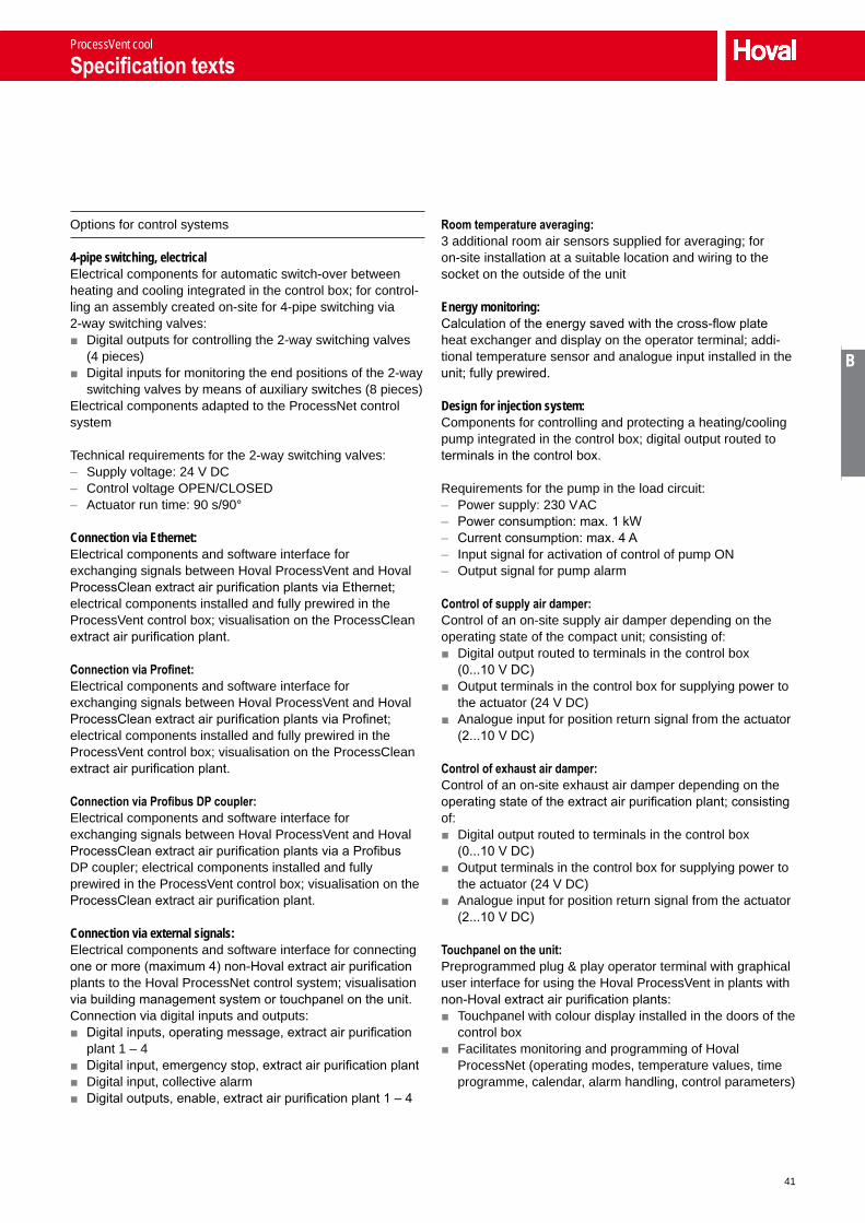
Options for control systems
4-pipe switching, electricalElectrical components for automatic switch-over between heating and cooling integrated in the control box; for control-ling an assembly created on-site for 4-pipe switching via 2-way switching valves:
■ Digital outputs for controlling the 2-way switching valves (4 pieces)
■ Digital inputs for monitoring the end positions of the 2-way switching valves by means of auxiliary switches (8 pieces)
Electrical components adapted to the ProcessNet control system
Technical requirements for the 2-way switching valves: – Supply voltage: 24 V DC – Control voltage OPEN/CLOSED – Actuator run time: 90 s/90°
Connection via Ethernet:Electrical components and software interface for exchanging signals between Hoval ProcessVent and Hoval ProcessClean extract air purification plants via Ethernet; electrical components installed and fully prewired in the ProcessVent control box; visualisation on the ProcessClean extract air purification plant.
Connection via Profinet:Electrical components and software interface for exchanging signals between Hoval ProcessVent and Hoval ProcessClean extract air purification plants via Profinet; electrical components installed and fully prewired in the ProcessVent control box; visualisation on the ProcessClean extract air purification plant.
Connection via Profibus DP coupler:Electrical components and software interface for exchanging signals between Hoval ProcessVent and Hoval ProcessClean extract air purification plants via a Profibus DP coupler; electrical components installed and fully prewired in the ProcessVent control box; visualisation on the ProcessClean extract air purification plant.
Connection via external signals:Electrical components and software interface for connecting one or more (maximum 4) non-Hoval extract air purification plants to the Hoval ProcessNet control system; visualisation via building management system or touchpanel on the unit.Connection via digital inputs and outputs:
■ Digital inputs, operating message, extract air purification plant 1 – 4
■ Digital input, emergency stop, extract air purification plant ■ Digital input, collective alarm ■ Digital outputs, enable, extract air purification plant 1 – 4
Room temperature averaging:3 additional room air sensors supplied for averaging; for on-site installation at a suitable location and wiring to the socket on the outside of the unit
Energy monitoring:Calculation of the energy saved with the cross-flow plate heat exchanger and display on the operator terminal; addi-tional temperature sensor and analogue input installed in the unit; fully prewired.
Design for injection system:Components for controlling and protecting a heating/cooling pump integrated in the control box; digital output routed to terminals in the control box.
Requirements for the pump in the load circuit: – Power supply: 230 V AC – Power consumption: max. 1 kW – Current consumption: max. 4 A – Input signal for activation of control of pump ON – Output signal for pump alarm
Control of supply air damper:Control of an on-site supply air damper depending on the operating state of the compact unit; consisting of:
■ Digital output routed to terminals in the control box (0...10 V DC)
■ Output terminals in the control box for supplying power to the actuator (24 V DC)
■ Analogue input for position return signal from the actuator (2...10 V DC)
Control of exhaust air damper:Control of an on-site exhaust air damper depending on the operating state of the extract air purification plant; consisting of:
■ Digital output routed to terminals in the control box (0...10 V DC)
■ Output terminals in the control box for supplying power to the actuator (24 V DC)
■ Analogue input for position return signal from the actuator (2...10 V DC)
Touchpanel on the unit:Preprogrammed plug & play operator terminal with graphical user interface for using the Hoval ProcessVent in plants with non-Hoval extract air purification plants:
■ Touchpanel with colour display installed in the doors of the control box
■ Facilitates monitoring and programming of Hoval ProcessNet (operating modes, temperature values, time programme, calendar, alarm handling, control parameters)
ProcessVent cool
Specification texts

42
Power supply:Power supply for Hoval ProcessVent if this is installed in conjunction with non-Hoval extract air purification plants. The power supply contains the following components:
■ Mains power terminals ■ Circuit breaker to protect the supply air fans of the Hoval
ProcessVent ■ 3-pin safety relay installed in the control box doors ■ In the design for injection system: circuit breaker to protect
the heating pump
Technical data
General:Nominal air quantity: ______________m³/hExternal available pressure: _______________ Pa
Dimensions (length x width x height):Base unit: 2000 x 1850 x 2904 mmFresh air module: 1631 x 700 x 1430 mmTotal: 2000 x 1850 x 4334 mm
Weight:Base unit: _______________ kgFresh air module: _______________ kgTotal: _______________ kg
Fans:Supply voltage: 3 x 400 V AC/50 HzPower consumption: ______________ kWCurrent consumption: ________________ ASpeed of rotation (nominal): ______________ rpmProtection rating: IP 54
Sound data:Sound power level:– Duct connection, fresh air: _____________dB(A)– Duct connection, supply air: _____________dB(A)– Displacement flow diffuser: _____________dB(A)Sound pressure level at 1 m distance from the unit: _____________dB(A)
Heat recovery:Fresh air temperature: _______________ °CFresh air relative humidity: ________________%Extract air temperature: _______________ °CExtract air relative humidity: _______________ %
Heat recovery efficiency, dry: ________________%Heat recovery efficiency, moist: ________________%Pressure drop: _______________ Pa
Technical data, heating coil:Heat output: _______________kWFlow/return: _______________ °CSupply air temperature: _______________ °CAt air inlet temperature: _______________ °COperating pressure: ______________ kPa
Technical data, cooling coil:Cooling capacity: _______________kWFlow/return: _______________ °CSupply air temperature: _______________ °CAt air inlet temperature: _______________ °COperating pressure: ______________ kPa
ProcessVent cool
Specification texts

43
ProcessVent PVCompact unit for ventilating production halls with heat recovery from process air
C
1 Use ____________________________________ 44
2 Construction and operation__________________ 44
3 Unit type reference ________________________ 48
4 Technical data ____________________________ 48
5 Specification texts _________________________ 52
ProcessVent
Contents

44
1 Use
1.1 Intended use
The ProcessVent unit is used to recover heat from process air and supply fresh air to halls containing enclosed machine tools or welding plants. The extract air from the extract air purification plant flows through a plate heat exchanger in an oil-tight design and is routed to the outside via a duct; the heat it contains is transferred to the supply air.
Intended use also includes compliance with the installation, commissioning, operating and servicing conditions (operating manual).Any use above and beyond this is deemed improper. The manufacturer can accept no liability for damage resulting from improper use.
1.2 User group
The unit may only be installed, operated and serviced by authorised and trained specialist personnel who are familiar with the unit and aware of the risks involved.The operating manual is intended for English-speaking oper-ating engineers and technicians and for specialist building services, heating and ventilation technology personnel.
2 Construction and operation
The ProcessVent unit forms one overall system with the extract air purification plant: The extract air purification plant draws off soiled air from machine tools or welding plants by means of a fan. It purifies this process air and transports it onwards through the extract air duct to the ProcessVent unit.
The ProcessVent unit fulfils the following functions: ■ Fresh air supply ■ Extract air removal (with air conveyance via the extract air purification plant)
■ Recovery of heat from the process air ■ Recirculation operation ■ Air filtration
Machine tool
Extract air purification plant
ProcessVent
Fig. C1: The ProcessVent unit forms one overall system with the extract air purifica-tion plant.
ProcessVent
Use

45
A
B
C
D
E
F
G
2.1 Construction
Condensate connection
Access door, extract air
Duct connection, extract air
Supply air fans
Fresh air filter (class F7) with filter monitoring
Duct connection, fresh air
Access door, fresh air
Control box
Plate heat exchanger with frost monitoring
ER and bypass damper with continuous actuator
Duct connection, exhaust air
Recirculation air inlet
Fresh air/recirculation damper with continuous actuator
Access door, exhaust air
Access panels, supply air (on all sides)
Supply air duct connection, rear
Fig. C2: Unit construction
ProcessVent
Construction and operation
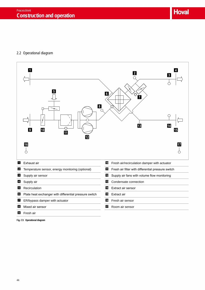
46
2.2 Operational diagram
Exhaust air
Temperature sensor, energy monitoring (optional)
Supply air sensor
Supply air
Recirculation
Plate heat exchanger with differential pressure switch
ER/bypass damper with actuator
Mixed air sensor
Fresh air
Fresh air/recirculation damper with actuator
Fresh air filter with differential pressure switch
Supply air fans with volume flow monitoring
Condensate connection
Extract air sensor
Extract air
Fresh air sensor
Room air sensor
Fig. C3: Operational diagram
ProcessVent
Construction and operation

47
A
B
C
D
E
F
G
2.3 Operating modes
The unit has the following operating modes: ■ Ventilation ■ Supply air ■ Night cooling summer ■ Off
The ProcessNet control system or the higher-level building management system controls the overall plant automatically. The operating mode of the ProcessVent units depends on:
■ the time programme ■ the operating states of the machines from which the
process air is to be drawn offThe following applies: When the machines are in operation, the ProcessVent unit always works in 'Ventilation' mode. The operating mode defined in the time programme is overridden.You can also control the operating mode of the ProcessVent unit manually and thus independently of the overall plant (e.g. for maintenance activities).You will find a detailed description of the ProcessNet control system in Section F 'Control systems' of this handbook.
Code ProcessVent operating mode Description
VE VentilationThe unit blows fresh air into the room. The fresh air quantity is constant; it is dependent on the extract air volume flow. The extract air from the extract air purification plant flows through the plate heat exchanger into the open air.The room temperature set value day is active. Energy recovery is controlled depending on the heat demand and temperature conditions.
Supply air fan.....................On 1)
Energy recovery ................0 – 100%Fresh air damper ...............OpenRecirculation damper.........Closed
1) Nominal volume flow as per setting in the control system (adjusted to the extract air volume flow)
SA Supply airThe unit blows fresh air into the room. The fresh air quantity is constant. Room air flows into the open via open doors and windows or is drawn off via an external system.
Supply air fan.....................On 1)
Energy recovery ................0%Fresh air damper ...............OpenRecirculation damper.........Closed
1) Nominal volume flow as per setting in the control system
NCS Night cooling summerOn/off operation with room temperature set value night:
■ If current temperatures permit, the unit blows cool fresh air into the room and thus uses it for free cooling.
■ If current temperatures do not permit free cooling, the unit switches off.
Supply air fan.....................On 1) 2)
Energy recovery ................0%Fresh air damper ...............Open 2)
Recirculation damper.........Closed 2)
1) Volume flow set in the control system2) Depending on temperature conditions
OFF OffThe unit is switched off.
Supply air fan.....................OffEnergy recovery ................0%Fresh air damper ...............ClosedRecirculation damper.........Open
ProcessVent
Construction and operation

48
3 Unit type reference
PV - 10 - / ...
Unit type ProcessVent
Unit size10
CoilWithout coil
OptionsYou will find a detailed description of all optional components in Section D 'Options' of this handbook.
4 Technical data
4.1 Application limits
Extract air temperature max. 50 °C
Extract air relative humidity (incl. oil vapours) max. 100 %
Dust content of extract air max. 5 mg/m³
Oil content of extract air 1) max. 10 mg/m³
Fresh air temperature min. -30 °C
Ambient temperature 4 … 40 °C
Supply air temperature max. 60 °C
Amount of condensate (at up to 10 m delivery head) max. 1.2 m³/h
Differential pressure fresh air/extract air max. 2500 Pa
Overpressure/underpressure max. 1500 Pa1) Conventional mineral, synthetic and ester oils and emulsions from the field of machining
Table C1: Application limits
■ The unit is not suitable for use in potentially explosive atmospheres. ■ The unit is not suitable for use in rooms with active humidification. ■ The unit is corrosion-protected, but only suitable for use in applications where the extract air contains very aggressive substances (sulphur, methanol, acetone, toluene, etc.) to a limited extent. Please contact Hoval applications support.
ProcessVent
Unit type reference

49
A
B
C
D
E
F
G
4.2 Air flow rate, electrical connections
Air distribution Nominal air flow rate 1) 10 000 m³/h
Heat recovery Heat recovery efficiency, dry 61 %
Heat recovery efficiency, moist (max.) 95 %
Fan characteristics Supply voltage 3 x 400 V AC
Permitted voltage tolerance ±10 %
Frequency 50 Hz
Nominal power consumption 2 x 2.4 kW
Current consumption 2 x 3.9 A
Speed of rotation (nominal) 2400 rpm
Actuators Supply voltage 24 V DC
Control voltage 2…10 V DC
Filter Filter class F7
Factory setting, pressure monitor 250 Pa
Plate heat exchanger Factory setting, pressure monitor 250 Pa1) Control range 3000…12000 m³/h The air flow rate depends on the extract air volume flow. Operation at minimum air flow rate is only recommended in partial load operation or intermittent operation.
Table C2: Technical data
Unit type PV-10
Available pressure Pa 570
Table C3: Available fan pressure to compensate for external pressure drops (at nominal air flow rate)
4.3 Sound level
Position Duct connection, fresh air
Duct connection, supply air
Displacement flow diffuser
(option)
Sound power level dB(A) 71 66 75
Sound pressure level dB(A) – – 59 1)
1) Applies at a distance of 1 m from the unit, measuring surface sound pressure level according to DIN 45636
Table C4: Sound level
ProcessVent
Technical data

50
4.4 Energy recovery
The data applies for the nominal air flow rate of 10 000 m³/h. The actual values are dependent on the actual air flow rate. The percentage change in these values for volume flows in the range 8 000…12 000 m³/h is shown in Diagram C1. For air flow rates under 8 000 m³/h, please contact Hoval appli-cations support.
60%
80%
100%
120%
140%
8000 9000 10000 11000 12000
Air flow rate in m³/h
Energy recovery
Supply air temperature
Diagram C1: Changes in output data depending on the air flow rate
Fresh air -15 °C/90% -5 °C/90%tExt rhExt QER tS QER tS
°C % kW °C kW °C15 20 62 4 41 7
40 65 4 42 860 70 6 45 880 77 8 50 10
100 84 10 57 1220 20 73 7 52 10
40 77 8 53 1160 85 10 58 1280 93 13 65 15
100 101 15 73 1725 20 84 10 62 14
40 90 12 65 1560 99 15 72 1780 109 18 81 19
100 119 21 91 2230 20 95 14 73 17
40 104 16 78 1860 115 19 86 2180 126 23 97 24
100 137 26 107 27Legend: tExt = Extract air temperature
rhExt = Extract air humidityQER = Energy recovery outputtS = Supply air temperature
Table C5: Energy recovery output of the ProcessVent
ProcessVent
Technical data

51
A
B
C
D
E
F
G
4.5 Dimensions and weights
19051850 2000
1040
2707471475187.5
180
180
140
47.5
288 340 288
∅ 63.5270
235
1246
1246
1040
235
235
370
159
340
344
2465
4324
3059
990230 1515 255 = =
1745
Extract air duct connection
Fresh air duct connection
Exhaust air duct connection
Supply air duct connection, rear
Fresh air module
Base unit
Fig. C4: Dimensional drawing (dimensions in mm)
ProcessVent
Technical data

52
Unit type PV-10
Components Base unit kg 1417
Fresh air module kg 240
Total kg 1657
Table C6: Weights
5 Specification texts
ProcessVent
Compact unit for ventilating production halls with heat recovery from process air, consisting of:
■ Fresh air module ■ Base unit with heat recovery in an oil-tight design, air
treatment and air introduction ■ Control system ■ Optional components
Fresh air module
Self-supporting, double-shell, foamed panel construction with insulation free of thermal bridges made of closed-cell polyurethane (PUR, building materials class B1 according to DIN 4102-1); equipped with jack rings for transport and installation on-site.
The fresh air module contains:
Fresh air/recirculation damper:Opposed dampers for switching between fresh air and recir-culation operation, including continuous actuator with safety function in the event of a power failure.
Fresh air filter:Designed as a compact filter of class F7, including differential pressure switch for filter monitoring.
Standard fanS
Supply air fans:Designed as maintenance-free, direct-drive radial fans with high-efficiency EC motors, backwards-curved, 3D contoured blades and a free-running rotating wheel made of a high-performance composite material; infinitely variable (2 pieces).
HigH-preSSure fanS
High-pressure fans:Designed as maintenance-free, direct-drive radial fans with high-efficiency EC motors, backwards-curved blades and a free-running rotating wheel made of aluminium; infinitely variable (2 pieces); in a high-pressure design to compensate for external pressure drops (e.g. through air ducts).
Duct connection, fresh air:Compensator with ventilation flange, fits on flange S30, for connection to the on-site fresh air duct.
Access door, fresh air:Large access opening for easily accessing the fresh air filter and the fans for maintenance purposes.
ProcessVent
Specification texts

53
A
B
C
D
E
F
G
freSH air module, uprigHt
The fresh air module is intended for upright installation on the base unit and equipped with plug-in connections for easy electrical installation.
freSH air module, Horizontal
The fresh air module is intended for horizontal installation on the base unit and equipped with plug-in connections for easy electrical installation; including connection duct and transverse support made of sheet steel, welded, with high-quality anti-corrosion primer and paint finish.
paint finiSH aS deSired
The casing of the fresh air module is painted in the RAL colour of the customer's choice.
Base unit with heat recovery in an oil-tight design, air treat-ment and air introduction
Supporting framework construction made of steel sections, welded, with high-quality anti-corrosion primer and paint finish; bottom tray made of sheet steel, water and oil-tight, with high-quality anti-corrosion primer and paint finish; cover panels made of aluzinc sheet steel; equipped with jack rings and fork-lift openings for transport and installation on-site.
The base unit contains:
Cross-flow plate heat exchanger:In a water and oil-tight design to recover heat from process air. Exchanger package consists of epoxy-coated aluminium plates with pressed-in spacers. The plates have a keyed fold connection with one another, which multiplies the mate-rial strength for the air inlet and outlet. The corners of the exchanger package are stuck into the aluminium press-drawn hollow sections of the casing with a sealing compound to form a water and oil-tight seal. The side walls made of sheet steel with a high-quality anti-corrosion primer and paint finish are screwed flush with these corners and sealed so they are water and oil-tight. A bypass is positioned in the flow of supply air and sealed so it is air and oil-tight against the extract air side; leak test according to company standard. Opposed ER and bypass damper mounted on the casing to control the output of the cross-flow plate heat exchanger, including continuous actuator. Frost monitoring on the extract air side by means of differential pressure switch.
Condensate drip tray with drain:In a water and oil-tight design to remove oily condensate from the cross-flow plate heat exchanger, with high-quality anti-corrosion primer and paint finish.
Extract air and exhaust air duct section:Water and oil-tight welded construction made of steel for conveying air containing oil, insulated with closed-cell Poly-cell (building materials class B2 according to DIN 4102-1), equipped with media-resistant compensators (2 pieces) with DIN flanged connecting pieces for connection to the on-site extract air and exhaust air duct.
Fresh air duct section:Transition between the fresh air module and the cross-flow plate heat exchanger, made of aluzinc sheet steel, insu-lated with closed-cell Polycell (building materials class B2 according to DIN 4102-1).
Supply air duct section:Transition between the cross-flow plate heat exchanger and the air introduction section, made of aluzinc sheet steel.
Supply air duct connection, rear
Air outlet box with supply air duct section:Connection to the on-site air distribution system, equipped with a compensator with ventilation flange, fits on flange S30, for connection to the on-site supply air duct (on the rear of the unit).
Supply air duct connection, left
Air outlet box with supply air duct section:Connection to the on-site air distribution system, equipped with a compensator with ventilation flange, fits on flange S30, for connection to the on-site supply air duct (on the left of the unit).
diSplacement flow diffuSer
Displacement flow diffuser:Cover panels towards the bottom of the base unit designed as a displacement flow diffuser for introducing the supply air into the occupied area in a low-pulse, duct-free manner; consisting of:
■ Outlet panel designed as a perforated sheet ■ Fabric mat for air distribution ■ Spring rods for attaching the fabric mat
Access openings: ■ Access door, exhaust air: large access opening for easily accessing the cross-flow plate heat exchanger for mainte-nance purposes; panel designed with a water and oil-tight closing system
■ Access door, extract air: large access opening for easily accessing the condensate drip tray with drain for mainte-nance purposes; panel designed with a water and oil-tight closing system
■ Access panel, supply air: large revision openings on all sides (4 pieces) with panels for easily accessing other components for maintenance purposes (depending on equipment: ER and bypass damper, return pump station, condensate drain).
ProcessVent
Specification texts

54
Control box with control module as part of the Hoval ProcessNet control system:
■ Control box made of sheet steel, powder-coated with textured paint in light grey (RAL 7035), integrated flush with the framework construction
■ Control module fully prewired with all I/O components: – Supply air fans – Actuator, fresh air/recirculation damper – Actuator, ER/bypass damper – Temperature sensor, mixed air – Temperature sensor, supply air – Frost monitoring, plate heat exchanger – Differential pressure switch, fresh air filter – Volume flow monitoring, supply air fans – Optional components as required
■ Room and fresh air sensors supplied with plug, for on-site installation at a suitable location and wiring to the socket on the outside of the unit
■ Mains power terminals ■ Fuse for the electronics ■ Transformer for control module and actuators ■ Cable glands designed as cable feedthrough plates
Standard paint finiSH
The following components of the base unit are painted in Hoval red (RAL 3000):
■ Framework construction ■ Bottom tray ■ Side walls of the plate heat exchanger ■ Condensate drip tray ■ Extract air and exhaust air duct section
paint finiSH aS deSired
The following components of the base unit are painted in the RAL colour of the customer's choice:
■ Framework construction ■ Bottom tray ■ Side walls of the plate heat exchanger ■ Condensate drip tray ■ Extract air and exhaust air duct section
Options for the unit
Return pump station water:Pump station for returning condensate for recycling or disposal; suitable for water-emulsion mixtures; installed in the unit, fully electrically prewired; consisting of:
■ Hosing from condensate drains to pump receiver ■ Pump receiver ■ Submersible pump ■ Check valve ■ Level probe
Technical data: – Pump output: 25 l/min – Delivery head: 8 m – Motor output: 0.14 kW – Speed of rotation: 2 700 rpm – Voltage: 3 x 400 V AC – Frequency: 50 Hz – Protection rating: IP 55 – Pump material: PPS – Pump shaft material: 1.4104 – Pump receiver material: SJ235R – Piping material: Threaded pipe according to DIN 2440, seamlessly galvanised, including fittings; PVC fabric hoses
– Nominal diameter of the connections: ¾ "
Return pump station oil:Pump station for returning condensate for recycling or disposal; suitable for oily condensate from the plate heat exchanger (with an upstream oil separator); installed in the unit, fully electrically prewired; consisting of:
■ Hosing from condensate drains to pump receiver ■ Pump receiver ■ Submersible pump ■ Check valve ■ Level probe
Technical data: – Pump output: 25 l/min – Delivery head: 8 m – Motor output: 0.14 kW – Speed of rotation: 2 700 rpm – Voltage: 3 x 400 V AC – Frequency: 50 Hz – Protection rating: IP 55 – Pump material: PPS – Pump shaft material: 1.4104 – Pump receiver material: SJ235R – Piping material: Threaded pipe according to DIN 2440, seamlessly galvanised, including fittings; PVC fabric hoses
– Nominal diameter of the connections: ¾ "
ProcessVent
Specification texts

55
A
B
C
D
E
F
G
Control systems
Control system for the energy-optimised operation of Hoval ProcessVent plants, designed as a decentralised I/O system, with the following main features:
■ Control module integrated in every unit, for autonomous and individual regulation of the units, allowing for precise adaptation to the operating conditions
■ Master-slave function for forming zones of several units being operated under the same conditions (e.g. same room temperature set values, same operating times)
■ Operating mode switching via – Time programme, holiday and vacation calendar – Specification of a building management system
■ The following control functions are performed by the control module: – Control of energy recovery depending on the tempera-
ture conditions – Control of supply air temperature via fixed value control
or room air/supply air cascade control – Fixed value control of volume flow – Soft starting to protect the unit when switching over to
operating states with fresh air – Defrosting if plate heat exchanger is iced up using the flow of extract air during plant operation
– Messages relating to the plant's heat or cool demand for external heating and refrigerating systems
– Fire control: connection for an external signal to shut the plant down in the event of a fire
– Signal for controlling external extract air systems when the plant is in an operating state where only fresh air is supplied to the hall and no extract air is removed from it (supply air/night cooling summer operating mode)
■ Simple connection of the units to a building management system via an interface integrated in the control module by means of the Profinet protocol in order to exchange the following data: – Current operating mode – Temperature control strategy – Temperature set values – Temperature actual values – Damper positions – Alarms – Energy meter (energy monitoring option)
■ Alarm handling via control module by means of 1 collec-tive alarm routed to terminal and transmission of alarm signals for visualisation
■ Running time meter for each unit ■ Back-up and restore function for easy saving of user
settings and loading of factory settings ■ Electrical documentation supplied in the control box
Options for control systems
Connection via Ethernet:Electrical components and software interface for exchanging signals between Hoval ProcessVent and Hoval ProcessClean extract air purification plants via Ethernet; electrical components installed and fully prewired in the ProcessVent control box; visualisation on the ProcessClean extract air purification plant.
Connection via Profinet:Electrical components and software interface for exchanging signals between Hoval ProcessVent and Hoval ProcessClean extract air purification plants via Profinet; electrical components installed and fully prewired in the ProcessVent control box; visualisation on the ProcessClean extract air purification plant.
Connection via Profibus DP coupler:Electrical components and software interface for exchanging signals between Hoval ProcessVent and Hoval ProcessClean extract air purification plants via a Profibus DP coupler; electrical components installed and fully prewired in the ProcessVent control box; visualisation on the ProcessClean extract air purification plant.
Connection via external signals:Electrical components and software interface for connecting one or more (maximum 4) non-Hoval extract air purification plants to the Hoval ProcessNet control system; visualisation via building management system or touchpanel on the unit.Connection via digital inputs and outputs:
■ Digital inputs, operating message, extract air purification plant 1 – 4
■ Digital input, emergency stop, extract air purification plant ■ Digital input, collective alarm ■ Digital outputs, enable, extract air purification plant 1 – 4
Room temperature averaging:3 additional room air sensors supplied for averaging; for on-site installation at a suitable location and wiring to the socket on the outside of the unit
Energy monitoring:Calculation of the energy saved with the cross-flow plate heat exchanger and display on the operator terminal; addi-tional temperature sensor and analogue input installed in the unit; fully prewired.
ProcessVent
Specification texts

56
Control of supply air damper:Control of an on-site supply air damper depending on the operating state of the compact unit; consisting of:
■ Digital output routed to terminals in the control box (0...10 V DC)
■ Output terminals in the control box for supplying power to the actuator (24 V DC)
■ Analogue input for position return signal from the actuator (2...10 V DC)
Control of exhaust air damper:Control of an on-site exhaust air damper depending on the operating state of the extract air purification plant; consisting of:
■ Digital output routed to terminals in the control box (0...10 V DC)
■ Output terminals in the control box for supplying power to the actuator (24 V DC)
■ Analogue input for position return signal from the actuator (2...10 V DC)
Touchpanel on the unit:Preprogrammed plug & play operator terminal with graphical user interface for using the Hoval ProcessVent in plants with non-Hoval extract air purification plants:
■ Touchpanel with colour display installed in the doors of the control box
■ Facilitates monitoring and programming of Hoval ProcessNet (operating modes, temperature values, time programme, calendar, alarm handling, control parameters)
Power supply:Power supply for Hoval ProcessVent if this is installed in conjunction with non-Hoval extract air purification plants. The power supply contains the following components:
■ Mains power terminals ■ Circuit breaker to protect the supply air fans of the Hoval
ProcessVent ■ 3-pin safety relay installed in the control box doors ■ In the design for injection system: circuit breaker to protect
the heating pump
Technical data
General:Nominal air quantity: ______________m³/hExternal available pressure: _______________ Pa
Dimensions (length x width x height):Base unit: 2000 x 1850 x 2904 mmFresh air module: 1631 x 700 x 1430 mmTotal: 2000 x 1850 x 4334 mm
Weight:Base unit: _______________ kgFresh air module: _______________ kgTotal: _______________ kg
Fans:Supply voltage: 3 x 400 V AC/50 HzPower consumption: ______________ kWCurrent consumption: ________________ ASpeed of rotation (nominal): ______________ rpmProtection rating: IP 54
Sound data:Sound power level:– Duct connection, fresh air: _____________dB(A)– Duct connection, supply air: _____________dB(A)– Displacement flow diffuser: _____________dB(A)Sound pressure level at 1 m distance from the unit: _____________dB(A)
Heat recovery:Fresh air temperature: _______________ °CFresh air relative humidity: ________________%Extract air temperature: _______________ °CExtract air relative humidity: _______________ %
Heat recovery efficiency, dry: ________________%Heat recovery efficiency, moist: ________________%Pressure drop: _______________ Pa
ProcessVent
Specification texts

57
Options D
1 Unit type reference ________________________ 58
2 High-pressure fans (HV) ____________________ 60
3 Air outlet ________________________________ 60
4 Fresh air module, horizontal (AH) _____________ 61
5 Paint finish as desired (AL) __________________ 62
6 Hydraulic assembly for diverting system (HY) ___ 62
7 4-pipe switching __________________________ 63
8 Return pump station _______________________ 64
Options
Contents

58
1 Unit type reference
PVH - 10 A / SV . K1 . AS . SL / HY . U1 .RW / PN . ET .MR / EM . ES . ZK . FK / TP . LV
Unit typePV ProcessVentPVH ProcessVent heat (with heating coil)PVC ProcessVent cool (with heating/cooling coil)
Unit size10
CoilA, B, C Heating coil type A, B or CC, D Heating/cooling coil type C or D- Without
FansSV Standard fansHV High-pressure fans
Air outletK1 Supply air duct connection, rear (standard)K2 Supply air duct connection, leftQL Displacement flow diffuser
Fresh air moduleAS Fresh air module, upright (standard)AH Fresh air module, horizontal
Paint finishSL Standard paint finishAL Paint finish as desired
Hydraulic assembly for diverting system-- Without (standard)HY Hydraulic assembly for diverting system
4-pipe switching-- Without (standard)U1 4-pipe switching, completeU2 4-pipe switching, only electrical components
Return pump station-- Without (standard)RW Return pump station waterRO Return pump station oilR2 Return pump station water and oil
Options
Unit type reference

59
A
B
C
D
E
F
G
PVH - 10 A / SV . K1 . AS . SL / HY . U1 .RW / PN . ET .MR / EM . ES . ZK . FK / TP . LV
ControlPN Design for ProcessNet (standard)
Connection, extract air purificationET Ethernet (standard)PT ProfinetPK Profibus DP couplerIO Connection via external signals (I/O)
Room temperature averaging-- Without (standard)MR Room temperature averaging
Energy monitoring-- Without (standard)EM Energy monitoring
Injection system-- Without (standard)ES Design for injection system
Control of supply air damper-- Without (standard)ZK Control of supply air damper
Control of exhaust air damper-- Without (standard)FK Control of exhaust air damper
Visualisation-- External visualisation (standard)TP Touchpanel on the unit
Power supply-- Without (standard)LV Power supply
Options
Unit type reference

60
2 High-pressure fans (HV)
High-pressure fans are EC fans with a higher available pres-sure to compensate for external pressure drops (e.g. through air ducts). They replace the standard fans.
Supply voltage 3 x 400 V AC
Permitted voltage tolerance ±10 %
Frequency 50 Hz
Nominal power consumption 2 x 4.1 kW
Current consumption 2 x 6.5 A
Speed of rotation (nominal) 2900 rpm
Table D1: Fan characteristics of the high-pressure fans
Unit type PV PVH PVCCoil – A B C C D
Available pressure Pa 810 760 740 670 580 500
Table D2: Available high-pressure fan pressure to compensate for external pressure drops (at nominal air flow rate)
Position Duct connection,
fresh air
Duct connection,
supply air
Displacement flow diffuser
(option)
Sound power level dB(A) 78 74 81
Sound pressure level
dB(A) – – 65 1)
1) Applies at a distance of 1 m from the unit, measuring surface sound pressure level according to DIN 45636
Table D3: Sound level of the units with high-pressure fans (at nominal air flow rate)
3 Air outlet
3.1 Supply air duct connection, left (K2)
The compensator for the supply air duct is mounted on the left side of the unit.
Fig. D1: Unit with supply air duct connection on left
140
1040
925
344 34
0
925
Fig. D2: Dimensional drawing for supply air duct connection on left ( dimensions in mm)
Options
High-pressure fans (HV)

61
A
B
C
D
E
F
G
3.2 Displacement flow diffuser (QL)
Units with a displacement flow diffuser introduce the supply air into the occupied area in a low-pulse, duct-free manner. The bottom section of the base unit is covered with perfo-rated sheets on all sides. Behind these sheets is a fabric mat, which is attached with spring rods, for air distribution.
Fig. D3: Unit with displacement flow diffuser
4 Fresh air module, horizontal (AH)For reasons of space, it can make sense to install the fresh air module on the base unit horizontally, rather than upright. To achieve this, the unit can be supplied complete with a connection duct and a support made of sheet steel. The connection duct must be insulated on-site (30 mm with heat transfer coefficient λ = 0.04 W/mK).
Fig. D4: Unit with fresh air module installed horizontally
2862862
3340
2465
3059
3675
442
Fig. D5: Dimensional drawing for fresh air module, horizontal (dimensions in mm)
Options
Fresh air module, horizontal (AH)

62
5 Paint finish as desired (AL)
The following components are painted in Hoval red (RAL 3000) as standard:
■ Framework construction ■ Bottom tray ■ Side walls of the plate heat exchanger ■ Condensate drip tray ■ Extract air and exhaust air duct section
These components and the casing of the fresh air module can be painted in any other colour as an option (state the RAL number in the order).
6 Hydraulic assembly for diverting system (HY)
There is an assembly for the hydraulic diverting system installed in the unit. It is fully insulated and comprises the following components:
■ 3-way control ball valve ■ Line balancing valve STAD ■ Ball valve ■ Pipes ■ Screw joints for easy connection to the on-site distributor
circuit (on the back of the unit)
Coil 3-way control ball valve Flow/return connectionDN Kvs
A B C 25 10 m³/h External thread 1½ "
D 32 16 m³/h External thread 2 "
Table D4: Technical data of the hydraulic assembly for diverting system
Supply voltage 24 V DC
Control voltage 0…10 V DC
Operating range 2…10 V DC
Position response 2…10 V DC
Actuator run time 4 s
Table D5: Technical data of the 3-way control ball valve
Fig. D6: Connections of the hydraulic assembly for diverting system
440
70
225 215
500
1672
Return
Flow
Fig. D7: Dimensional drawing for hydraulic connections (dimensions in mm)
Options
Paint finish as desired (AL)

63
A
B
C
D
E
F
G
7 4-pipe switching
The 4-pipe switching allows automatic switch-over between heating and cooling in systems with 2 separate hydraulic circuits.
7.1 4-pipe switching, complete (U1)
An assembly for automatic switch-over is attached to the unit. It is fully insulated and comprises the following compo-nents:
■ 2-way switching valves with auxiliary switch ■ Shut-off ball valves ■ Piping to the hydraulic assembly for diverting system ■ Screw joints for easy connection to the on-site distributor
circuit
The electrical components for automatic switch-over are installed and prewired in the terminal box.
Coil DN Flow/return connection
Stroke/force
Type C 25 External thread 1½ " 10 Nm
Type D 32 External thread 2 " 10 Nm
Table D6: Technical data of the 4-pipe switching assembly
Supply voltage 24 V DC
Control voltage OPEN/CLOSED
Actuator run time 90 s
Table D7: Technical data of the 2-way switching valves
7.2 4-pipe switching, only electrical components (U2)
The electrical components for automatic switch-over are installed in the terminal box (4-pipe switching assembly and wiring on-site; see electrical schematic for connections).
Fig. D8: Unit with 4-pipe switching
170
733
508
1671
250
250
250
Heating return
Cooling return
Heating flow
Cooling flow
Fig. D9: Dimensional drawing for 4-pipe switching (dimensions in mm)
Options
4-pipe switching

64
8 Return pump station
8.1 Return pump station water (RW)
The return pump station water is used for the removal of condensate in applications where connection to the waste water system via a simple condensate line is not possible. It drains the following media or returns them to the process for recycling:
■ Water-emulsion mixtures from the plate heat exchanger (with an upstream emulsion separator, wet separator or dry filter)
■ Condensate from the cooling coil
The return pump station is installed and prewired in the unit.
8.2 Return pump station oil (RO)
The return pump station oil is used for the removal of condensate in applications where connection to the waste water system via a simple condensate line is not possible. It drains the following media or returns them to the process for recycling:
■ Oily condensate from the plate heat exchanger (with an upstream oil separator)
The return pump station is installed and prewired in the unit.
Output 25 l/min
Delivery head 8 m
Supply voltage 3 x 400 V AC
Frequency Hz 50
Condensate drain connection ¾" (internal thread)
Table D8: Technical data of the return pump stations (water and oil)
Fig. D10: Return pump station installed in the unit
Notice You will find a description of the options for control systems in Section F 'Control systems' of this hand-book.
Options
Return pump station

65
Transport and installation E
1 Assembly ________________________________ 66
2 Hydraulic installation _______________________ 68
3 Electrical installation _______________________ 69
Transport and installation
Contents
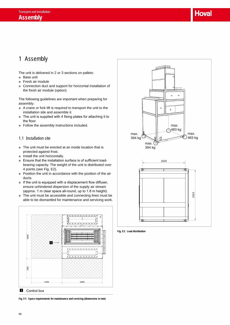
66
1 Assembly
The unit is delivered in 2 or 3 sections on pallets: ■ Base unit ■ Fresh air module ■ Connection duct and support for horizontal installation of
the fresh air module (option)
The following guidelines are important when preparing for assembly:
■ A crane or fork lift is required to transport the unit to the installation site and assemble it.
■ The unit is supplied with 4 fixing plates for attaching it to the floor.
■ Follow the assembly instructions included.
1.1 Installation site
■ The unit must be erected at an inside location that is protected against frost.
■ Install the unit horizontally. ■ Ensure that the installation surface is of sufficient load-
bearing capacity. The weight of the unit is distributed over 4 points (see Fig. E2).
■ Position the unit in accordance with the position of the air ducts.
■ If the unit is equipped with a displacement flow diffuser, ensure unhindered dispersion of the supply air stream (approx. 1 m clear space all-round, up to 1.8 m height).
■ The unit must be accessible and connecting lines must be able to be dismantled for maintenance and servicing work.
9002000
1400 1850
Control box
Fig. E1: Space requirements for maintenance and servicing (dimensions in mm)
max.394 kg
max.394 kg
max.483 kg
max.483 kg
1620
1910
Fig. E2: Load distribution
Transport and installation
Assembly

67
A
B
C
D
E
F
G
1.2 Connecting the air ducts
■ The extract air and exhaust air duct is designed according to plant-specific conditions: – In plants with an upstream oil/emulsion separator or
with minimal quantity lubrication (MQL), the ducts must have an oil-tight design.
– In plants with an upstream dry filter or wet separator, the ducts must be designed in galvanised sheet steel.
■ The unit must not be subjected to the weight of the ducts. Suspend the ducts from the ceiling or support them on the floor.
■ Connect the air ducts via the compensators so they are free of tension and vibrations.
■ Insulate the fresh air and exhaust air duct, including the compensator, right up to the point where it leaves the building (30 mm with heat transfer coefficient λ = 0.04 W/mK).
■ Arrange the fresh air suction and the exhaust air outlet via the roof in the opposite direction to prevent a short circuit.
53515
∅ 8
1100
535
400
1537
0
Fig. E3: Dimensional drawing for fresh air and supply air duct (dimensions in mm)
1372
125 × 9 = 1125 98.5
∅12 (28×)
98.5252511
3.5
113.
512
5
402
288
1246
Fig. E4: Dimensional drawing for extract air and exhaust air duct (dimensions in mm)
Transport and installation
Assembly

68
2 Hydraulic installation
2.1 Heating/cooling coil
■ Warm or hot water up to a max. temperature of 120 °C can be used as a heating medium.
■ Connect the heating/cooling coil in accordance with the hydraulic schematic.
■ Depending on local conditions, check whether compensa-tors for linear expansion are required for the supply and return lines and/or articulated connections are required for the units.
■ Insulate the hydraulic lines. ■ Hydraulically coordinate the individual units within one
control group so that uniform pressure admission is ensured.
■ Do not apply any loads to the coil, e.g. by means of the flow or return.
■ The condensate separator in cooling units only functions while the fan is running. No coolant must be allowed to circulate in the heating/cooling coil when the unit is switched off.
Notice Use the options 'Hydraulic assembly‘ and '4-pipe switching‘ for quick and easy hydraulic installation.
882
1366
484
AB
Dimension PVH-10ABC PVC-10C PVC-10D
A 1015 1015 1006
B 78 78 95
Fig. E5: Dimensional drawing for hydraulic connections (dimensions in mm)
Return Flow
2.2 Condensate connection
Condensate arising in the plate heat exchanger and possibly in the cooling section must be removed via a condensate line.
■ Adequately size the slope and cross section of the condensate line to prevent a condensate backwash.
■ Make sure that the condensate can drain off freely. ■ Depending on the specific application, the condensate
may contain residue of oil, emulsions and cooling lubri-cants. Ensure that the condensate is disposed of or recycled in accordance with local regulations.
Nominal sizes
Plate heat exchanger condensate connection 2"
Cooling section condensate connection ¾"
Table E1: Nominal sizes of the condensate connections
To prevent air escaping via the condensate line, the line must be connected via a trap (pipe trap or hose trap). The height of the trap depends on the maximum overpressure of the extract air purification plant fan (pmax):
Pipe trap
HHu
H = 0.1 ∙ pmaxHu = H + 75
Example:pmax = 1000 PaH = 0.1 ∙ 1000 = 100 mmHu = 100 + 75 = 175 mm
Hose trap
HuBR
BR = 0.1 ∙ pmax + 25Hu = 0.2 ∙ pmax + 150
Example:pmax = 1000 PaBR = 0.1 ∙ 1000 + 25 = 125 mmHu = 0.2 ∙ 1000 + 150 = 350 mm
Legend: pmax = Fan overpressure in Pa BR = Bending radius of the hose in mm (depending on the
hose used)
Table E2: Calculation of the effective height for the trap
■ Connect the trap directly at the condensate connection. ■ Fill the trap with water before commissioning, after each cleaning operation and after an extended downtime.
Transport and installation
Hydraulic installation

69
A
B
C
D
E
F
G
Cable feedthroughs 1)
Plug-in connection, base unit – fresh air module
Access door, fresh air
Plug-in connections, temperature sensor
Control box
Equipotential bonding on the unit frame
1) On the unit design with a displacement flow diffuser, no cable feedthroughs are provided at the bottom near to the floor.
3 Electrical installation
■ Observe all applicable regulations (e.g. EN 60204-1) . ■ For long supply lines, select cable cross-sections in
accordance with the technical regulations. ■ Carry out electrical installation in accordance with the
wiring diagram. ■ Route the cables for the control systems separate from
mains cables. ■ Establish the plug-in connection between the base unit and the fresh air module (see Fig. E6): – Open the fresh air access door. – Establish plug-in connections as shown in the wiring
diagram. ■ The room air sensor and the fresh air sensor are supplied loose in the control box. Install the temperature sensors at a suitable location and wire them to the plug-in connec-tions on the unit.
■ Connect the unit frame with the foundation earth electrode and label it with an earthing label.
■ Secure all connections against working loose.
Fig. E6: Electrical installation
Transport and installation
Electrical installation

70
Designation Reference Voltage Cable CommentPower supply 3 x 400 V AC 5 x 4 mm²Connection, extract air purification Ethernet/Profinet CAT5e RJ45 Max. length 100 m
Profibus DP coupler 2 x 0.34 mm² Shielded, max. length 200 m at 1 500 kbit/s
External signalsOperating message, extract air purification 1 2 x 1.0 mm²Operating message, extract air purification 2 2 x 1.0 mm²Operating message, extract air purification 3 2 x 1.0 mm²Operating message, extract air purification 4 2 x 1.0 mm²Enable, extract air purification 1 Volt-free 2 x 1.0 mm² Max. 6 A, 250 V, 1 500 VAEnable, extract air purification 2 Volt-free 2 x 1.0 mm² Max. 6 A, 250 V, 1 500 VAEnable, extract air purification 3 Volt-free 2 x 1.0 mm² Max. 6 A, 250 V, 1 500 VAEnable, extract air purification 4 Volt-free 2 x 1.0 mm² Max. 6 A, 250 V, 1 500 VAEmergency stop, extract air purification 2 x 1.0 mm²Collective alarm, extract air purification 2 x 1.0 mm²
Enable heating PVH / PVC Volt-free 2 x 1.0 mm² Max. 6 A, 250 V, 1 500 VAEnable cooling PVC Volt-free 2 x 1.0 mm² Max. 6 A, 250 V, 1 500 VAHeating/cooling switch-over PVC Volt-free 2 x 1.0 mm² Max. 6 A, 250 V, 1 500 VAMixing valve PVH / PVC with on-site mixing valve 24 V DC 4 x 0.75 mm² With option 'Hydraulic
assembly' installed and prewired in the unit
Fresh air sensor 2 x 0.5 mm² Plug suppliedRoom air sensor 2 x 0.5 mm² Plug suppliedOptions
Room temperature averaging 3 x 0.5 mm² Plug supplied4-pipe switching, only elec-trical components
Switching valve, heating flow 24 V DC 3 x 0.75 mm² Power supply6 x 0.75 mm² Control line
Switching valve, heating return 24 V DC 3 x 0.75 mm² Power supply6 x 0.75 mm² Control line
Switching valve, cooling flow 24 V DC 3 x 0.75 mm² Power supply6 x 0.75 mm² Control line
Switching valve, cooling return 24 V DC 3 x 0.75 mm² Power supply6 x 0.75 mm² Control line
Pump in the load circuit (injection system)
230 V AC 4 x 1.5 mm² Power supply 24 V DC 4 x 0.5 mm² Control line
Control of supply air damper 24 V DC 4 x 0.75 mm²Control of exhaust air damper 24 V DC 4 x 0.75 mm²Collective alarm Volt-free 3 x 1.5 mm² Max. 6 A, 250 V, 1 500 VAFire alarm Volt-free 2 x 1.0 mm² Max. 6 A, 250 V, 1 500 VAExternal extract air system Volt-free 2 x 1.0 mm² Max. 6 A, 250 V, 1 500 VABMS integration CAT5e RJ45 System bus
Table E3: Cable list for on-site connections
Transport and installation
Electrical installation

71
Control systems F
1 ProcessNet system set-up __________________ 72
2 Control functions __________________________ 75
3 Safety functions ___________________________ 75
4 Control options ___________________________ 76
5 Alarms and monitoring _____________________ 77
6 BMS parameter list ________________________ 78
Control systems
Contents

72
op
er
atio
n
GLT
MASTER SLAVE
un
itS
fur
tHe
r c
om
mu
nic
atio
n
Building management system (optional)
ProcessMaster operator terminal
System bus
Machines (machine tool, welding plant)
Extract air purification plant
ProcessVent
Overall system, extract air purification and indoor climate control
Other plants
Fig. F1: ProcessNet system set-up
1 ProcessNet system set-up
The Hoval ProcessNet control system regulates and controls the overall plant automatically and ensures that all compo-nents are operated in an energy-efficient manner according to need. It is set up as a decentralised I/O system.
Temperature sensor (fresh air, room air)Enable heatingEnable coolingHeating/cooling switch-overMixing valve4-pipe switchingPump in the load circuit for injection systemControl of supply air damperControl of exhaust air damperCollective alarmFire alarmExternal extract air system
Control systems
ProcessNet system set-up

73
A
B
C
D
E
F
G
1.1 Basic principles
Overall system, extract air purification and indoor climate controlA control module is installed in every ProcessVent to allow for autonomous and individual control. This module commu-nicates with the assigned extract air purification plant via the system bus, forming an overall system with said plant.The operating mode for this overall system is defined via the time programme or by the building management system. The actual operating state also depends on whether the extracting machines are operational or shut down.
Zone formationIn plants with several such overall systems, control zones are formed according to the master-slave concept.
■ The master defines the current set values for room control.
■ The slaves adopt the set values which apply to them, depending on their current operating mode. Therefore, they continue to work autonomously, according to the extracting machines and the time programme or the building management system.
1.2 Operation
ProcessMaster operator terminalThe ProcessMaster serves as the operator terminal. It is a touchpanel that provides an easy and clear way to operate the plant. The ProcessMaster gives the user access to all required information and settings:
■ Display and set operating modes ■ Display temperatures and set room temperature set
values ■ Display and program the time programme and the
calendar ■ Display and handle alarms ■ Display and set control parameters
There are 2 options for positioning the ProcessMaster: ■ In plants with Hoval ProcessClean extract air purification
plants, the ProcessMaster is installed in the ProcessClean control box.
■ In plants with non-Hoval extract air purification plants, the ProcessMaster is installed in the ProcessVent control box (touchpanel on the unit option).
Integration into the building management system (BMS)ProcessNet can be easily integrated into the building management system via an integrated interface. Data is exchanged via Profinet with the following data blocks:
■ DB320 (receive) ■ DB321 (send)
You will find a full parameter list in Chapter 6.
Control systems
ProcessNet system set-up
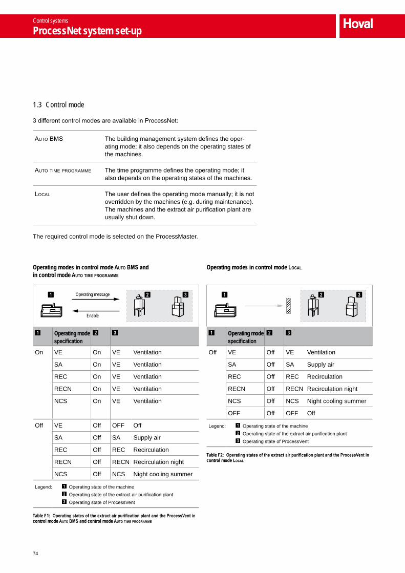
74
Operating modes in control mode Auto BMS and in control mode Auto tiMe progrAMMe
Operating mode specification
On VE On VE Ventilation
SA On VE Ventilation
REC On VE Ventilation
RECN On VE Ventilation
NCS On VE Ventilation
Off VE Off OFF Off
SA Off SA Supply air
REC Off REC Recirculation
RECN Off RECN Recirculation night
NCS Off NCS Night cooling summer
Legend: Operating state of the machine Operating state of the extract air purification plant Operating state of ProcessVent
Table F1: Operating states of the extract air purification plant and the ProcessVent in control mode Auto BMS and control mode Auto tiMe progrAMMe
Operating message
Enable
Operating modes in control mode LocAL
Operating mode specification
Off VE Off VE Ventilation
SA Off SA Supply air
REC Off REC Recirculation
RECN Off RECN Recirculation night
NCS Off NCS Night cooling summer
OFF Off OFF Off
Legend: Operating state of the machine Operating state of the extract air purification plant Operating state of ProcessVent
Table F2: Operating states of the extract air purification plant and the ProcessVent in control mode LocAL
1.3 Control mode
3 different control modes are available in ProcessNet:
auto BmS The building management system defines the oper-ating mode; it also depends on the operating states of the machines.
auto time programme The time programme defines the operating mode; it also depends on the operating states of the machines.
local The user defines the operating mode manually; it is not overridden by the machines (e.g. during maintenance). The machines and the extract air purification plant are usually shut down.
The required control mode is selected on the ProcessMaster.
Control systems
ProcessNet system set-up

75
A
B
C
D
E
F
G
2 Control functions
2.1 Room temperature control in extract air operation
The room temperature can be controlled in 2 different ways in extract air operation – that is, in the VE (ventilation) and SA (supply air) operating modes. The control strategy can be selected via the software:
■ Room air/supply air cascade control: A set value is defined for the room temperature. Dependent on the actual value of the room temperature and the current control deviation, the PI controller defines a set value for the supply air temperature.
■ Supply air temperature control: A set value is defined for the supply air temperature. The supply air temperature is regulated to this set value; the room temperature is not taken into account here.
To reach the set value, ProcessNet controls the components in the following order:
■ The ER damper is opened. ■ The heating or cooling mixing valve is opened. ■ The supply air volume flow is reduced to an adjustable minimum volume flow.
2.2 Room temperature control in recirculation operation
In recirculation operation – that is, in the REC (recircula-tion) and RECN (recirculation night) operating modes – ProcessNet controls the room temperature via the patented TempTronic algorithm; this ensures that heating and/or cooling is performed in the most cost-effective manner possible.A set value is defined for the room temperature. The air is blown into the room at the maximum permitted supply air temperature in heating operation or at the minimum permitted supply air temperature in cooling operation. The supply air volume flow is controlled dependent on the actual value of the room temperature and the current control devia-tion.
2.3 Control of the supply air volume flow
The supply air volume flow is controlled and thus adapted to the extract air volume flow. The set value (= nominal volume flow) is defined via the ProcessMaster or the building management system.
3 Safety functions
3.1 Soft starting
The soft starting function prevents the coil from freezing when switching from recirculation to extract air operation. The coil is preheated and the fresh air damper is initially opened only as much as is necessary for the mixed air temperature to be in the frost-free range. Only once the supply air temperature has reached the set value is the fresh air damper opened fully.
3.2 Defrost switch
When fresh air temperatures are very low, condensate in the extract air may freeze. To protect against icing up, the pressure drop in the plate heat exchanger is monitored. If this becomes too large, the unit switches to defrost operation automatically:
ProcessVent heat/coolThe fresh air flows through the bypass. The warm extract air defrosts the exchanger.
ProcessVentThe unit switches to recirculation operation.
3.3 Frost protection switch
■ If the supply air temperature drops below a defined value (6 K above the set frost protection temperature), the heating mixing valve is opened continuously.
■ If the supply air temperature drops below the frost protec-tion temperature, the frost alarm is displayed and the device switches off.
The frost protection temperature can be regulated.
3.4 Fan overrun
The fan overrun is used to cool the coil down or dry it out when heating or cooling operation is being switched off. The required time is defined via the ProcessMaster.
Notice To avoid underpressure or overpressure arising in the building, set the overrun time for the extract air fan of the extract air purification plant to the same value.
Control systems
Control functions

76
4 Control options
4.1 Connection, extract air purification
Ethernet (ET)The extract air purification plant is connected to the unit via Ethernet:
■ Data exchange via defined interface ■ Visualisation on the extract air purification plant (no touch-
panel on the unit)
Profinet (PT)The extract air purification plant is connected to the unit via Profinet:
■ Data exchange via defined interface ■ Visualisation on the extract air purification plant (no touch-
panel on the unit)
Profibus DP coupler (PK)The extract air purification plant is connected to the unit via Profibus DP coupler:
■ Data exchange via defined interface ■ Visualisation on the extract air purification plant (no touch-
panel on the unit)
Connection via external signals (IO)One or more (max. 4) non-Hoval extract air purification plants are connected to the unit via external signals. The fresh air quantity of the ProcessVent unit depends on the extract air volume flow of the individual plants. Where several plants are operated in parallel, the values are added up accordingly.
■ Visualisation via building management system or touch-panel on the unit
Digital inputs ■ Operating message, extract air purification plant 1 – 4
■ Emergency stop, extract air purifi-cation plant
■ Collective alarm
Digital outputs ■ Enable for extract air purification plant 1 – 4
Table F3: Digital inputs and outputs with connection via external signals
4.2 Room temperature averaging (MR)
4 room air sensors for averaging in the occupied area are supplied (wiring to be provided on-site).
4.3 Energy monitoring (EM)
Energy monitoring determines the amount of energy recov-ered in the plate heat exchanger (separate counters for heating and cooling energy) and displays it on the operator terminal. For this reason, there is an additional temperature sensor installed and prewired in the unit.
4.4 Design for injection system (ES)
Instead of a diverting system, an injection system can also be installed in the load circuit. In the design for injection system, additional components for control of the pumps in the load circuit are installed in the control box.
Requirements for the pump in the load circuit: – Power supply: 230 V AC – Power consumption: max. 1 kW – Current consumption: max. 4 A – Input signal for activation of control of pump ON – Output signal for pump alarm
4.5 Control of supply air damper (ZK)
Hoval ProcessNet can control an on-site supply air damper. This control is performed dependent on an adjustable threshold value for the supply air volume flow.
Supply voltage 24 V DC
Control voltage 0…10 V DC
Return signal 2…10 VDC
Table F4: Control of supply air damper
4.6 Control of exhaust air damper (FK)
Hoval ProcessNet can control an on-site exhaust air damper. This control is performed dependent on the operating state of the extract air purification plant(s).
Supply voltage 24 V DC
Control voltage 0…10 V DC
Return signal 2…10 VDC
Table F5: Control of exhaust air damper
Control systems
Control options

77
A
B
C
D
E
F
G
4.7 Touchpanel on the unit (TP)
The touchpanel on the unit serves as an operator terminal in systems with non-Hoval extract air purification plants. It gives trained users access to all information and settings that are necessary for normal operation:
■ Display and set operating modes ■ Display temperatures and set temperature set values ■ Display and programme the time programme ■ Display and handle alarms ■ Display and set control parameters
4.8 Power supply (LV)
In systems with non-Hoval extract air purification plants, the power supply for the unit can be integrated in the terminal box (with safety relay).
5 Alarms and monitoring
The Hoval ProcessNet monitors itself. All alarms are entered in the alarm list and displayed on the operator terminal. Priority A alarms are also displayed via a collective alarm indicator installed on-site as required.
Alarm Priority Cause System response 1) Remedy
Fire alarm A Signal for fire alarm active ■ The fresh air damper closes. ■ The unit switches off.
Check external fire alarm signal.
Emergency stop, extract air purification plant A Emergency stop signal for extract air purifica-
tion plant active ■ The fresh air damper closes. ■ The unit switches off.
Check extract air purifica-tion, switch off emergency stop if required.
Communication fault, extract air purification A Communication between extract air purifica-
tion and ProcessVent interrupted or faulty ■ The fresh air damper closes. ■ The unit switches off. Contact customer service.
Fault accessing analogue input module A Internal PLC fault ■ The fresh air damper closes.
■ The unit switches off. Contact customer service.
Fault accessing analogue output module A Internal PLC fault ■ The fresh air damper closes.
■ The unit switches off. Contact customer service.
Fan 1 not ready A Fan 1 defective or control faulty ■ The fresh air damper closes. ■ The unit switches off. Contact customer service.
Fan 2 not ready A Fan 2 defective or control faulty
Plate heat exchanger soiled (plant off) A Differential pressure of the plate heat
exchanger too high for an extended period ■ The fresh air damper closes. ■ The unit switches off.
Clean the plate heat exchanger.
Coil frost alarm A Supply air temperature lower than frost protection temperature
■ The fresh air damper closes. ■ The unit switches off. ■ The mixing valve opens
100%.
Contact customer service.
Maximum supply air temperature exceeded A Current supply air temperature higher than
maximum permitted supply air temperature ■ The fresh air damper closes. ■ The unit switches off. Contact customer service.
Supply air sensor (incorrect parameter settings) A
Supply air sensor defective ■ The fresh air damper closes. ■ The unit switches off. Contact customer service.Supply air sensor
(cable break/short circuit) A
Supply air sensor (outside measuring range) A
1) If ProcessNet is also controlling on-site supply air or exhaust air dampers, these are closed too.
Table F6: Extract from the alarm list (priority A alarms)
Control systems
Alarms and monitoring

78
6 BM
S pa
ram
eter
list
Addr
ess
Offs
etSy
mbo
l nam
eTy
peDe
faul
tLo
wer li
mit
Uppe
r limi
tUn
itCo
mm
ent
GLT_
Rcv (
DB 32
0)Co
mm
unica
tion
0,0
GLT_
Rcv.L
ifeBi
tBO
OLFA
LSE
Comm
unica
tion
monit
oring
: life
bit f
rom
BMS
Oper
atin
g m
odes
2,0
GLT_
Rcv.O
pMod
e.Cu
rrent
Mode
INT
11
5Op
erat
ing m
ode
(1 =
VE;
2 =
REC
; 3 =
REC
N; 4
= S
A; 5
= N
CS)
Cont
rol s
trate
gy 4
,0GL
T_Rc
v.Tem
pCtrl
Stra
tegy
BOOL
FALS
ETe
mper
ature
contr
ol str
ategy
(0 =
supp
ly air
temp
. con
trol; 1
= ro
om ai
r/sup
ply ai
r cas
cade
contr
ol)Se
t valu
es 6
,0GL
T_Rc
v.SP.R
oomT
empD
ayRE
AL18
.05.
040
.0°C
Set v
alue,
room
temp
erat
ure
day:
vent
ilatio
n (V
E), r
ecirc
ulatio
n (R
EC),
supp
ly air
(SA)
10,0
GLT_
Rcv.S
P.Roo
mTem
pNigh
tRE
AL16
.05.
040
.0°C
Set v
alue,
room
temp
erat
ure
night
: rec
ircula
tion
night
(REC
N), n
ight c
oolin
g su
mmer
(NCS
)14
,0GL
T_Rc
v.SP.S
upply
AirT
emp
REAL
19.0
5.0
40.0
°CSe
t valu
e, su
pply
air te
mper
atur
e: ve
ntila
tion
(VE)
, sup
ply a
ir (S
A)Ex
tern
al va
lue s
pecifi
catio
ns18
,0GL
T_Rc
v.Exte
rnal.
Temp
Fres
hAir
REAL
-60.
0-5
0.0
100.
0°C
Exte
rnal
value
, fre
sh a
ir te
mper
atur
e22
,0GL
T_Rc
v.Exte
rnal.
Temp
Room
REAL
-60.
0-5
0.0
100.
0°C
Exte
rnal
value
, roo
m te
mper
atur
e26
,0GL
T_Rc
v.Exte
rnal.
Mediu
mInd
icatio
nBO
OLFA
LSE
Exte
rnal
value
, hea
ting/
cooli
ng sw
itch-
over
(0 =
hea
ting;
1 =
cooli
ng)
GLT_
Send
(DB
321)
Com
mun
icatio
n0,
00,
0GL
T_Se
nd.L
ifeBi
tBO
OLFA
LSE
Comm
unica
tion
monit
oring
: tog
gling
life
bit to
BMS
(BMS
writ
es b
ack b
it 1:1
)Op
erat
ing
mod
e sele
ctor
2,0
0,0
GLT_
Send
.OpM
ode.
Selec
tor
INT
00
2Op
erat
ing m
ode
selec
tor,
cont
rol m
ode
(0 =
Loc
al; 1
= A
uto
time
prog
ramm
e; 2
= A
uto
BMS)
Oper
atin
g m
odes
4,0
0,0
GLT_
Send
.OpM
ode.
Curre
ntMo
deIN
T0
09
Curre
nt o
pera
ting
mode
(0 =
OFF
; 1 =
VE;
2 =
REC
; 3 =
REC
N; 4
= S
A; 5
= N
CS)
Oper
atin
g st
atus
, ext
ract
air p
urifi
catio
n6,
00,
0GL
T_Se
nd.S
epar
ator
Run
BOOL
FALS
ECu
rrent
ope
ratin
g sta
tus,
extra
ct air
pur
ificat
ion (0
= n
ot a
ctive
; 1 =
acti
ve)
Colle
ctive
alar
m8,
00,
0GL
T_Se
nd.C
ollec
tiveA
larm.
PrioA
BOOL
FALS
ECo
llecti
ve a
larm,
prio
rity A
(0 =
no
alarm
; 1 =
alar
m ac
tive)
→ p
lant s
tops
runn
ing8,
10,
1GL
T_Se
nd.C
ollec
tiveA
larm.
PrioB
BOOL
FALS
ECo
llecti
ve a
larm,
prio
rity B
(0 =
no
alarm
; 1 =
alar
m ac
tive)
→ p
lant c
ontin
ues t
o ru
nCo
ntro
l stra
tegy
10,0
0,0
GLT_
Send
.Temp
CtrlS
trate
gyBO
OLFA
LSE
Temp
eratu
re co
ntrol
strate
gy (0
= su
pply
air te
mp. c
ontro
l; 1 =
room
air/s
upply
air c
asca
de co
ntrol)
Set v
alues
12,0
0,0
GLT_
Send
.SP.R
oomT
empD
ayRE
AL18
.05.
040
.0°C
Set v
alue,
room
temp
erat
ure
day:
vent
ilatio
n (V
E), r
ecirc
ulatio
n (R
EC),
supp
ly air
(SA)
16,0
4,0
GLT_
Send
.SP.R
oomT
empN
ight
REAL
16.0
5.0
40.0
°CSe
t valu
e, ro
om te
mper
atur
e nig
ht: r
ecirc
ulatio
n nig
ht (R
ECN)
, nigh
t coo
ling
summ
er (N
CS)
20,0
8,0
GLT_
Send
.SP.S
upply
AirT
emp
REAL
19.0
5.0
40.0
°CSe
t valu
e, su
pply
air te
mper
atur
e: ve
ntila
tion
(VE)
, sup
ply a
ir (S
A)
Control systems
BMS parameter list

79
A
B
C
D
E
F
G
Addr
ess
Offs
etSy
mbo
l nam
eTy
peDe
faul
tLo
wer li
mit
Uppe
r limi
tUn
itCo
mm
ent
Actu
al va
lues
24,0
0,0
GLT_
Send
.PV.
Temp
Supp
lyAir
REAL
0.0
-60.
025
0.0
°CAc
tual
value
, sup
ply a
ir te
mper
atur
e28
,04,
0GL
T_Se
nd.P
V.Te
mpFr
eshA
irRE
AL0.
0-6
0.0
250.
0°C
Actu
al va
lue, f
resh
air
temp
erat
ure
32,0
8,0
GLT_
Send
.PV.
Temp
Exha
ustA
irRE
AL0.
0-6
0.0
250.
0°C
Actu
al va
lue, e
xtrac
t air
temp
erat
ure
36,0
12,0
GLT_
Send
.PV.
Temp
Room
REAL
0.0
-60.
025
0.0
°CAc
tual
value
, roo
m te
mper
atur
e40
,016
,0GL
T_Se
nd.P
V.Su
pplyA
irRE
AL0.
00.
0Ma
x.m³
/hAc
tual
value
, sup
ply a
ir vo
lume
flow
44,0
20,0
GLT_
Send
.PV.
Damp
erPo
sOut
sideA
irRE
AL0.
00.
010
0.0
%Ac
tual
value
, fre
sh a
ir da
mper
pos
ition
48,0
24,0
GLT_
Send
.PV.
Damp
erPo
sRec
ircula
tionA
irRE
AL0.
00.
010
0.0
%Ac
tual
value
, rec
ircula
tion
damp
er p
ositio
n52
,028
,0GL
T_Se
nd.P
V.Da
mper
PosE
RGRE
AL0.
00.
010
0.0
%Ac
tual
value
, ER
damp
er p
ositio
n56
,032
,0GL
T_Se
nd.P
V.Da
mper
PosB
ypas
sRE
AL0.
00.
010
0.0
%Ac
tual
value
, byp
ass d
ampe
r pos
ition
60,0
36,0
GLT_
Send
.PV.
Valve
PosR
egist
erRE
AL0.
00.
010
0.0
%Ac
tual
value
, mixi
ng va
lve64
,040
,0GL
T_Se
nd.P
V.De
mand
Heat
ingBO
OLFA
LSE
Actu
al va
lue, e
nable
hea
ting
(0 =
no
heat
dem
and;
1 =
hea
t dem
and)
64,1
40,1
GLT_
Send
.PV.
Dema
ndCo
oling
BOOL
FALS
EAc
tual
value
, ena
ble co
oling
(0 =
no
cool
dema
nd; 1
= co
ol de
mand
)64
,240
,2GL
T_Se
nd.P
V.Me
diumI
ndica
tion
BOOL
FALS
EAc
tual
value
, hea
ting/
cooli
ng sw
itch-
over
(0 =
hea
ting;
1 =
cooli
ng)
64,3
40,3
GLT_
Send
.PV.
Dema
ndEx
tractA
irSys
tem
BOOL
FALS
EAc
tual
value
, exte
rnal
extra
ct air
syste
m de
mand
(0 =
no
dema
nd; 1
= d
eman
d ac
tive)
Ener
gy m
onito
ring
66,0
0,0
GLT_
Send
.Mon
itorin
g.He
atFl
owRE
AL0.
0kW
Curre
nt h
eat fl
ow70
,04,
0GL
T_Se
nd.M
onito
ring.
CoolF
lowRE
AL0.
0kW
Curre
nt co
ol flo
w74
,08,
0GL
T_Se
nd.M
onito
ring.
Heat
Ener
gyRE
AL0.
0kW
hEn
ergy
savin
gs, h
eatin
g78
,012
,0GL
T_Se
nd.M
onito
ring.
CoolE
nerg
yRE
AL0.
0kW
hEn
ergy
savin
gs, c
oolin
gEx
tern
al va
lue s
pecifi
catio
ns82
,00,
0GL
T_Se
nd.E
xtern
al.Te
mpFr
eshA
irRE
AL20
.0-5
0.0
100.
0°C
Exte
rnal
value
, fre
sh a
ir te
mper
atur
e86
,04,
0GL
T_Se
nd.E
xtern
al.Te
mpRo
omRE
AL20
.0-5
0.0
100.
0°C
Exte
rnal
value
, roo
m te
mper
atur
e90
,08,
0GL
T_Se
nd.E
xtern
al.Me
diumI
ndica
tion
BOOL
FALS
EEx
tern
al va
lue, h
eatin
g/co
oling
switc
h-ov
er (0
= h
eatin
g; 1
= co
oling
)Sw
itch-
over
valu
e spe
cifica
tions
92,0
0,0
GLT_
Send
.Sou
rceS
electi
on.Te
mpFr
eshA
irBO
OLFA
LSE
Fres
h air
temp
erat
ure
switc
h-ov
er (0
= in
tern
al se
nsor
; 1 =
exte
rnal
spec
ificat
ion)
92,1
0,1
GLT_
Send
.Sou
rceS
electi
on.Te
mpRo
omBO
OLFA
LSE
Room
temp
erat
ure
switc
h-ov
er (0
= in
tern
al se
nsor
; 1 =
exte
rnal
spec
ificat
ion)
92,2
0,2
GLT_
Send
.Sou
rceS
electi
on.M
edium
Indic
ation
BOOL
FALS
EHe
ating
/cooli
ng sw
itch-
over
(0 =
inte
rnal
sens
or; 1
= e
xtern
al sp
ecific
ation
)
ALM_
UMAL
M_UM
.ALM
_Gen
eral
100,
00,
0AL
M_UM
.ALM
_Gen
eral.
Alm[
0] BO
OL0
No. 9
Pr. A
A009
: Fire
alar
m0,
1AL
M_UM
.ALM
_Gen
eral.
Alm[
1] BO
OL0
No. 1
0Pr
. AA0
10: E
merg
ency
stop
, extr
act a
ir pu
rifica
tion
plant
0,2
ALM_
UM.A
LM_G
ener
al.Al
m[2]
BOOL
0No
. 11
Pr. A
A011
: Com
munic
ation
fault
, extr
act a
ir pu
rifica
tion
(life
bit fa
ult)
0,3
ALM_
UM.A
LM_G
ener
al.Al
m[3]
BOOL
0No
. 12
Pr. A
A012
: Fau
lt acc
essin
g an
alogu
e inp
ut m
odule
0,4
ALM_
UM.A
LM_G
ener
al.Al
m[4]
BOOL
0No
. 13
Pr. A
A013
: Fau
lt acc
essin
g an
alogu
e ou
tput
mod
ule1,
0AL
M_UM
.ALM
_Gen
eral.
Alm[
8] BO
OL0
No. 1
Pr. B
B001
: Com
munic
ation
fault
, BMS
(life
bit f
ault)
1,1
ALM_
UM.A
LM_G
ener
al.Al
m[9]
BOOL
0No
. 2Pr
. BB0
02: A
ctual
value
from
BMS
, fre
sh a
ir te
mper
atur
e, lim
it valu
e fa
ult1,
2AL
M_UM
.ALM
_Gen
eral.
Alm[
10]
BOOL
0No
. 3Pr
. BB0
03: A
ctual
value
from
BMS
, roo
m te
mper
atur
e, lim
it valu
e fa
ult
Control systems
BMS parameter list
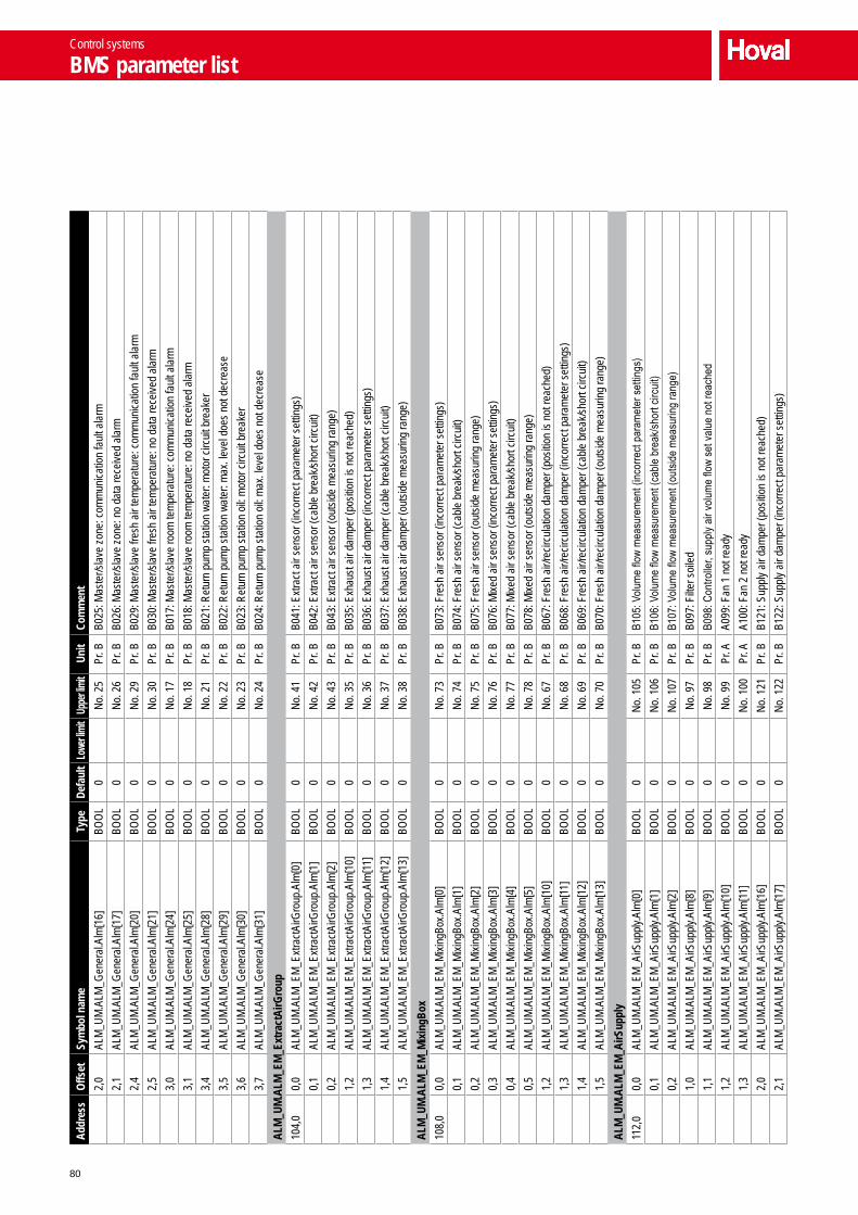
80
Addr
ess
Offs
etSy
mbo
l nam
eTy
peDe
faul
tLo
wer li
mit
Uppe
r limi
tUn
itCo
mm
ent
2,0
ALM_
UM.A
LM_G
ener
al.Al
m[16
] BO
OL0
No. 2
5Pr
. BB0
25: M
aste
r/slav
e zo
ne: c
ommu
nicat
ion fa
ult a
larm
2,1
ALM_
UM.A
LM_G
ener
al.Al
m[17
] BO
OL0
No. 2
6Pr
. BB0
26: M
aste
r/slav
e zo
ne: n
o da
ta re
ceive
d ala
rm2,
4AL
M_UM
.ALM
_Gen
eral.
Alm[
20]
BOOL
0No
. 29
Pr. B
B029
: Mas
ter/s
lave
fresh
air
temp
erat
ure:
comm
unica
tion
fault
alar
m2,
5AL
M_UM
.ALM
_Gen
eral.
Alm[
21]
BOOL
0No
. 30
Pr. B
B030
: Mas
ter/s
lave
fresh
air
temp
erat
ure:
no
data
rece
ived
alarm
3,0
ALM_
UM.A
LM_G
ener
al.Al
m[24
] BO
OL0
No. 1
7Pr
. BB0
17: M
aste
r/slav
e ro
om te
mper
atur
e: co
mmun
icatio
n fa
ult a
larm
3,1
ALM_
UM.A
LM_G
ener
al.Al
m[25
] BO
OL0
No. 1
8Pr
. BB0
18: M
aste
r/slav
e ro
om te
mper
atur
e: n
o da
ta re
ceive
d ala
rm3,
4AL
M_UM
.ALM
_Gen
eral.
Alm[
28]
BOOL
0No
. 21
Pr. B
B021
: Ret
urn
pump
stat
ion w
ater
: mot
or ci
rcuit
bre
aker
3,5
ALM_
UM.A
LM_G
ener
al.Al
m[29
] BO
OL0
No. 2
2Pr
. BB0
22: R
etur
n pu
mp st
ation
wat
er: m
ax. le
vel d
oes n
ot d
ecre
ase
3,6
ALM_
UM.A
LM_G
ener
al.Al
m[30
] BO
OL0
No. 2
3Pr
. BB0
23: R
etur
n pu
mp st
ation
oil:
moto
r circ
uit b
reak
er3,
7AL
M_UM
.ALM
_Gen
eral.
Alm[
31]
BOOL
0No
. 24
Pr. B
B024
: Ret
urn
pump
stat
ion o
il: ma
x. lev
el do
es n
ot d
ecre
ase
ALM_
UM.A
LM_E
M_Ex
tract
AirG
roup
104,
00,
0AL
M_UM
.ALM
_EM_
Extra
ctAirG
roup
.Alm
[0]
BOOL
0No
. 41
Pr. B
B041
: Extr
act a
ir se
nsor
(inc
orre
ct pa
rame
ter s
ettin
gs)
0,1
ALM_
UM.A
LM_E
M_Ex
tractA
irGro
up.A
lm[1
] BO
OL0
No. 4
2Pr
. BB0
42: E
xtrac
t air
sens
or (c
able
brea
k/sho
rt cir
cuit)
0,2
ALM_
UM.A
LM_E
M_Ex
tractA
irGro
up.A
lm[2
] BO
OL0
No. 4
3Pr
. BB0
43: E
xtrac
t air
sens
or (o
utsid
e me
asur
ing ra
nge)
1,2
ALM_
UM.A
LM_E
M_Ex
tractA
irGro
up.A
lm[1
0] BO
OL0
No. 3
5Pr
. BB0
35: E
xhau
st air
dam
per (
posit
ion is
not
reac
hed)
1,3
ALM_
UM.A
LM_E
M_Ex
tractA
irGro
up.A
lm[11
] BO
OL0
No. 3
6Pr
. BB0
36: E
xhau
st air
dam
per (
incor
rect
para
mete
r set
tings
)1,
4AL
M_UM
.ALM
_EM_
Extra
ctAirG
roup
.Alm
[12]
BOOL
0No
. 37
Pr. B
B037
: Exh
aust
air d
ampe
r (ca
ble b
reak
/shor
t circ
uit)
1,5
ALM_
UM.A
LM_E
M_Ex
tractA
irGro
up.A
lm[1
3] BO
OL0
No. 3
8Pr
. BB0
38: E
xhau
st air
dam
per (
outsi
de m
easu
ring
rang
e)AL
M_UM
.ALM
_EM_
Mixin
gBox
108,
00,
0AL
M_UM
.ALM
_EM_
Mixin
gBox
.Alm
[0]
BOOL
0No
. 73
Pr. B
B073
: Fre
sh a
ir se
nsor
(inc
orre
ct pa
rame
ter s
ettin
gs)
0,1
ALM_
UM.A
LM_E
M_Mi
xingB
ox.A
lm[1
] BO
OL0
No. 7
4Pr
. BB0
74: F
resh
air
sens
or (c
able
brea
k/sho
rt cir
cuit)
0,2
ALM_
UM.A
LM_E
M_Mi
xingB
ox.A
lm[2
] BO
OL0
No. 7
5Pr
. BB0
75: F
resh
air
sens
or (o
utsid
e me
asur
ing ra
nge)
0,3
ALM_
UM.A
LM_E
M_Mi
xingB
ox.A
lm[3
] BO
OL0
No. 7
6Pr
. BB0
76: M
ixed
air se
nsor
(inc
orre
ct pa
rame
ter s
ettin
gs)
0,4
ALM_
UM.A
LM_E
M_Mi
xingB
ox.A
lm[4
] BO
OL0
No. 7
7Pr
. BB0
77: M
ixed
air se
nsor
(cab
le br
eak/s
hort
circu
it)0,
5AL
M_UM
.ALM
_EM_
Mixin
gBox
.Alm
[5]
BOOL
0No
. 78
Pr. B
B078
: Mixe
d air
sens
or (o
utsid
e me
asur
ing ra
nge)
1,2
ALM_
UM.A
LM_E
M_Mi
xingB
ox.A
lm[1
0] BO
OL0
No. 6
7Pr
. BB0
67: F
resh
air/
recir
culat
ion d
ampe
r (po
sition
is n
ot re
ache
d)1,
3AL
M_UM
.ALM
_EM_
Mixin
gBox
.Alm
[11]
BOOL
0No
. 68
Pr. B
B068
: Fre
sh a
ir/re
circu
lation
dam
per (
incor
rect
para
mete
r set
tings
)1,
4AL
M_UM
.ALM
_EM_
Mixin
gBox
.Alm
[12]
BOOL
0No
. 69
Pr. B
B069
: Fre
sh a
ir/re
circu
lation
dam
per (
cable
bre
ak/sh
ort c
ircuit
)1,
5AL
M_UM
.ALM
_EM_
Mixin
gBox
.Alm
[13]
BOOL
0No
. 70
Pr. B
B070
: Fre
sh a
ir/re
circu
lation
dam
per (
outsi
de m
easu
ring
rang
e)AL
M_UM
.ALM
_EM_
AirS
uppl
y11
2,0
0,0
ALM_
UM.A
LM_E
M_Ai
rSup
ply.A
lm[0
] BO
OL0
No. 1
05Pr
. BB1
05: V
olume
flow
meas
urem
ent (
incor
rect
para
mete
r set
tings
)0,
1AL
M_UM
.ALM
_EM_
AirS
upply
.Alm
[1]
BOOL
0No
. 106
Pr. B
B106
: Volu
me flo
w me
asur
emen
t (ca
ble b
reak
/shor
t circ
uit)
0,2
ALM_
UM.A
LM_E
M_Ai
rSup
ply.A
lm[2
] BO
OL0
No. 1
07Pr
. BB1
07: V
olume
flow
meas
urem
ent (
outsi
de m
easu
ring
rang
e)1,
0AL
M_UM
.ALM
_EM_
AirS
upply
.Alm
[8]
BOOL
0No
. 97
Pr. B
B097
: Filte
r soil
ed1,
1AL
M_UM
.ALM
_EM_
AirS
upply
.Alm
[9]
BOOL
0No
. 98
Pr. B
B098
: Con
trolle
r, su
pply
air vo
lume
flow
set v
alue
not r
each
ed1,
2AL
M_UM
.ALM
_EM_
AirS
upply
.Alm
[10]
BOOL
0No
. 99
Pr. A
A099
: Fan
1 n
ot re
ady
1,3
ALM_
UM.A
LM_E
M_Ai
rSup
ply.A
lm[11
] BO
OL0
No. 1
00Pr
. AA1
00: F
an 2
not
read
y2,
0AL
M_UM
.ALM
_EM_
AirS
upply
.Alm
[16]
BOOL
0No
. 121
Pr. B
B121
: Sup
ply a
ir da
mper
(pos
ition
is no
t rea
ched
)2,
1AL
M_UM
.ALM
_EM_
AirS
upply
.Alm
[17]
BOOL
0No
. 122
Pr. B
B122
: Sup
ply a
ir da
mper
(inc
orre
ct pa
rame
ter s
ettin
gs)
Control systems
BMS parameter list

81
A
B
C
D
E
F
G
Addr
ess
Offs
etSy
mbo
l nam
eTy
peDe
faul
tLo
wer li
mit
Uppe
r limi
tUn
itCo
mm
ent
2,2
ALM_
UM.A
LM_E
M_Ai
rSup
ply.A
lm[1
8] BO
OL0
No. 1
23Pr
. BB1
23: S
upply
air
damp
er (c
able
brea
k/sho
rt cir
cuit)
2,3
ALM_
UM.A
LM_E
M_Ai
rSup
ply.A
lm[1
9] BO
OL0
No. 1
24Pr
. BB1
24: S
upply
air
damp
er (o
utsid
e me
asur
ing ra
nge)
ALM_
UM.A
LM_E
M_En
ergy
Reco
very
116,
00,
0AL
M_UM
.ALM
_EM_
Ener
gyRe
cove
ry.Al
m[0]
BOOL
0No
. 137
Pr. B
B137
: ER
damp
er (p
ositio
n is
not r
each
ed)
0,1
ALM_
UM.A
LM_E
M_En
ergy
Reco
very.
Alm[
1] BO
OL0
No. 1
38Pr
. BB1
38: E
R da
mper
(inc
orre
ct pa
rame
ter s
ettin
gs)
0,2
ALM_
UM.A
LM_E
M_En
ergy
Reco
very.
Alm[
2] BO
OL0
No. 1
39Pr
. BB1
39: E
R da
mper
(cab
le br
eak/s
hort
circu
it)0,
3AL
M_UM
.ALM
_EM_
Ener
gyRe
cove
ry.Al
m[3]
BOOL
0No
. 140
Pr. B
B140
: ER
damp
er (o
utsid
e me
asur
ing ra
nge)
1,0
ALM_
UM.A
LM_E
M_En
ergy
Reco
very.
Alm[
8] BO
OL0
No. 1
29Pr
. BB1
29: P
late
heat
exc
hang
er so
iled
(plan
t run
ning)
1,1
ALM_
UM.A
LM_E
M_En
ergy
Reco
very.
Alm[
9] BO
OL0
No. 1
30Pr
. AA1
30: P
late
heat
exc
hang
er so
iled
(plan
t off)
ALM_
UM.A
LM_E
M_He
atin
gCoi
l12
0,0
0,0
ALM_
UM.A
LM_E
M_He
ating
Coil.A
lm[0
] BO
OL0
No. 1
69Pr
. BB1
69: M
ixing
valve
(pos
ition
is no
t rea
ched
)0,
1AL
M_UM
.ALM
_EM_
Heat
ingCo
il.Alm
[1]
BOOL
0No
. 170
Pr. B
B170
: Mixi
ng va
lve (i
ncor
rect
para
mete
r set
tings
)0,
2AL
M_UM
.ALM
_EM_
Heat
ingCo
il.Alm
[2]
BOOL
0No
. 171
Pr. B
B171
: Mixi
ng va
lve (c
able
brea
k/sho
rt cir
cuit)
0,3
ALM_
UM.A
LM_E
M_He
ating
Coil.A
lm[3
] BO
OL0
No. 1
72Pr
. BB1
72: M
ixing
valve
(out
side
meas
uring
rang
e)1,
0AL
M_UM
.ALM
_EM_
Heat
ingCo
il.Alm
[8]
BOOL
0No
. 161
Pr. A
A161
: Coil
fros
t alar
m1,
1AL
M_UM
.ALM
_EM_
Heat
ingCo
il.Alm
[9]
BOOL
0No
. 162
Pr. B
B162
: Coil
fros
t pro
tecti
on1,
2AL
M_UM
.ALM
_EM_
Heat
ingCo
il.Alm
[10]
BOOL
0No
. 163
Pr. B
B163
: Hea
ting
mediu
m no
t ava
ilable
1,3
ALM_
UM.A
LM_E
M_He
ating
Coil.A
lm[11
] BO
OL0
No. 1
64Pr
. BB1
64: C
oolin
g me
dium
not a
vaila
ble1,
4AL
M_UM
.ALM
_EM_
Heat
ingCo
il.Alm
[12]
BOOL
0No
. 165
Pr. B
B165
: Flow
valve
, hea
ting
mediu
m: o
pen
retu
rn si
gnal
miss
ing1,
5AL
M_UM
.ALM
_EM_
Heat
ingCo
il.Alm
[13]
BOOL
0No
. 166
Pr. B
B166
: Flow
valve
, hea
ting
mediu
m: cl
osed
retu
rn si
gnal
miss
ing1,
6AL
M_UM
.ALM
_EM_
Heat
ingCo
il.Alm
[14]
BOOL
0No
. 167
Pr. B
B167
: Flow
valve
, hea
ting
mediu
m: b
oth
posit
ion m
essa
ges s
imult
aneo
usly
1,7
ALM_
UM.A
LM_E
M_He
ating
Coil.A
lm[1
5] BO
OL0
No. 1
68Pr
. BB1
68: R
etur
n va
lve, h
eatin
g me
dium:
ope
n re
turn
sign
al mi
ssing
2,0
ALM_
UM.A
LM_E
M_He
ating
Coil.A
lm[1
6] BO
OL0
No. 1
85Pr
. BB1
85: R
etur
n va
lve, h
eatin
g me
dium:
clos
ed re
turn
sign
al mi
ssing
2,1
ALM_
UM.A
LM_E
M_He
ating
Coil.A
lm[1
7] BO
OL0
No. 1
86Pr
. BB1
86: R
etur
n va
lve, h
eatin
g me
dium:
bot
h po
sition
mes
sage
s sim
ultan
eous
ly2,
2AL
M_UM
.ALM
_EM_
Heat
ingCo
il.Alm
[18]
BOOL
0No
. 187
Pr. B
B187
: Flow
valve
, coo
ling
mediu
m: o
pen
retu
rn si
gnal
miss
ing2,
3AL
M_UM
.ALM
_EM_
Heat
ingCo
il.Alm
[19]
BOOL
0No
. 188
Pr. B
B188
: Flow
valve
, coo
ling
mediu
m: cl
osed
retu
rn si
gnal
miss
ing2,
4AL
M_UM
.ALM
_EM_
Heat
ingCo
il.Alm
[20]
BOOL
0No
. 189
Pr. B
B189
: Flow
valve
, coo
ling
mediu
m: b
oth
posit
ion m
essa
ges s
imult
aneo
usly
2,5
ALM_
UM.A
LM_E
M_He
ating
Coil.A
lm[2
1] BO
OL0
No. 1
90Pr
. BB1
90: R
etur
n va
lve, c
oolin
g me
dium:
ope
n re
turn
sign
al mi
ssing
2,6
ALM_
UM.A
LM_E
M_He
ating
Coil.A
lm[2
2] BO
OL0
No. 1
91Pr
. BB1
91: R
etur
n va
lve, c
oolin
g me
dium:
clos
ed re
turn
sign
al mi
ssing
2,7
ALM_
UM.A
LM_E
M_He
ating
Coil.A
lm[2
3] BO
OL0
No. 1
92Pr
. BB1
92: R
etur
n va
lve, c
oolin
g me
dium:
bot
h po
sition
mes
sage
s sim
ultan
eous
lyAL
M_UM
.ALM
_EM_
Tem
pCtrl
124,
00,
0AL
M_UM
.ALM
_EM_
Temp
Ctrl.
Alm[
0] BO
OL0
No. 2
01Pr
. AA2
01: M
axim
um su
pply
air te
mper
atur
e ex
ceed
ed0,
1AL
M_UM
.ALM
_EM_
Temp
Ctrl.
Alm[
1] BO
OL0
No. 2
02Pr
. BB2
02: S
upply
air
temp
erat
ure
cont
rolle
r doe
s not
reac
h se
t valu
e1,
0AL
M_UM
.ALM
_EM_
Temp
Ctrl.
Alm[
8] BO
OL0
No. 1
93Pr
. BB1
93: S
upply
air
sens
or (i
ncor
rect
para
mete
r set
tings
)1,
1AL
M_UM
.ALM
_EM_
Temp
Ctrl.
Alm[
9] BO
OL0
No. 1
94Pr
. BB1
94: S
upply
air
sens
or (c
able
brea
k/sho
rt cir
cuit)
1,2
ALM_
UM.A
LM_E
M_Te
mpCt
rl.Al
m[10
] BO
OL0
No. 1
95Pr
. BB1
95: S
upply
air
sens
or (o
utsid
e me
asur
ing ra
nge)
1,3
ALM_
UM.A
LM_E
M_Te
mpCt
rl.Al
m[11
] BO
OL0
No. 1
96Pr
. BB1
96: R
oom
air se
nsor
(inc
orre
ct pa
rame
ter s
ettin
gs)
1,4
ALM_
UM.A
LM_E
M_Te
mpCt
rl.Al
m[12
] BO
OL0
No. 1
97Pr
. BB1
97: R
oom
air se
nsor
(cab
le br
eak/s
hort
circu
it)1,
5AL
M_UM
.ALM
_EM_
Temp
Ctrl.
Alm[
13]
BOOL
0No
. 198
Pr. B
B198
: Roo
m air
sens
or (o
utsid
e me
asur
ing ra
nge)
Control systems
BMS parameter list

82

83
System design G
1 Location of the temperature sensors __________ 84
2 Maintenance schedule _____________________ 84
3 General checklist _________________________ 84
System design
Contents

84
1 Location of the temperature sensors
1.1 Room air sensor
Install the sensor at a height of about 1.5 m in a representa-tive location in the occupied area. Its measured values must not be distorted by the presence of sources of heat or cold (machines, direct sunlight, windows, doors, etc.).Normally, you should use one room air sensor for each control zone. It is also possible to install four sensors to determine the average temperature value.
1.2 Fresh air sensor
Install the sensor at least 3 m above the ground on a north-facing wall, so that it is protected from direct sunlight. Provide additional cover for the sensor and thermally insulate it from the building.Only one fresh air sensor is needed per control zone.
2 Maintenance schedule
Activity Interval
Change the filter When the alarm 'Filter' is displayed, at least annually
Clean the plate heat exchanger and condensate drip tray
When the alarm 'PHE dirty' is displayed
Visually check the heating/cooling coil for dirt build-up and clean if necessary (PVH and PVC unit types only)
Every 3 months
Clean the return pump station (option)
Every 3 months
Comprehensive functional check and cleaning of the unit
Annually by the manufac-turer's customer service technicians
Table G1: Maintenance schedule
3 General checklist
■ Does the installation surface have sufficient load-bearing capacity?
■ Is the available fan pressure sufficient to compensate for pressure drops in the duct network?
■ Is there enough space to carry out maintenance and servicing work? Are the access doors accessible without obstacles?
■ Are there installation problems in the hall, such as crane-ways, false ceilings or similar?
■ Does the air quantity balance in the hall – that is, between the extract air purification plant and the ventilation system – need to be equalised?
■ Are the application limits complied with? ■ Does the extract air contain corrosive media? ■ Which heating/cooling medium is being used? ■ Are unit options required? ■ Are control system options required? ■ How are the control zones subdivided? ■ Where should the control panel, which contains the oper-
ating options, be positioned? ■ Do the units need to be connected to a central building
management system?
System design
Location of the temperature sensors


1
Hoval heating technology
As an energy-neutral supplier with a full range of products, Hoval helps its customers to select innovative system solutions for a wide range of energy sources, such as heat pumps, bio-mass, solar energy, gas, oil and district heating. Services range from private residential units to large-scale industrial projects.
Responsibility for energy and environmentThe Hoval brand is internationally known as one of the leading suppliers of indoor climate control solutions. More than 65 years of experience have given us the nec-essary capabilities and motivation to continuously develop exceptional solutions and technically advanced equipment. Maximising energy effi ciency and thus protecting the environment are both our commitment and our incentive. Hoval has established itself as an expert provider of intelligent heating and ventilation systems that are exported to over 50 countries worldwide.
Hoval comfort ventilation
Increased comfort and more effi cient use of energy from private housing to industrial halls: our comfort ventilation products pro-vide fresh, clean air for living and working space. Our innovative system for a healthy room climate uses heat and moisture recovery, while at the same time protecting energy resources and providing a healthier environment.
Hoval indoor climate systems
Indoor climate systems ensure top air quality and economical usability. Hoval has been installing decentralised systems for many years. The key is to combine multiple combinations of air-conditioners that can be controlled separately or together as a single system. This enables Hoval to respond fl exibly to a wide range of requirements for heating, cooling and ventilation.
Hoval heat recovery
Effi cient use of energy due to heat recovery. Hoval offers two different solutions: plate heat exchangers as a recuperative system and rotary heat exchangers as a regenerative system.
InternationalHoval Aktiengesellschaft Austrasse 709490 Vaduz, Liechtenstein Tel. +423 399 24 00Fax +423 399 27 31
United Kingdom Hoval Ltd. Northgate, Newark Nottinghamshire NG24 1JNTel. 01636 672711 Fax 01636 673532
ProcessVent Design HandbookSubject to technical alterationsArt.No. 4 212 167 – Edition 05 / 2013© Hoval Aktiengesellschaft, Liechtenstein, 2013