how automotive engineering is taking product line ... · how automotive engineering is taking...
TRANSCRIPT

How Automotive Engineering Is Taking Product Line Engineering to the Extreme
Len Wozniak
General Motors Company 3300 General Motors Road
Milford, MI 48380 +1 248 255 2332
Paul Clements BigLever Software
10500 Laurel Hill Cove Austin, Texas 78730 USA
+1 512 426 2227 [email protected]
ABSTRACT Automotive manufacturing ranks among the most extreme instances of systems and software product line engineering (PLE). The product family numbers in the millions, each product is highly complex in its own right, and the variation across products is literally astronomical in scale. This paper explores the aspects that make the domain extreme and the very specific implications they have for PLE. These implications include the need for efficient manufacturing, complexity management, concurrent development streams, globally distributed engineering and production, a hierarchical product family tree, multi-level variation binding, constraint management, and a highly robust and integrated PLE tooling environment. Happily, the PLE paradigm supporting these implications brings about a number of opportunities for analysis and automation that provide efficiencies of production previously unattainable. We focus on one example in depth: The management and automated generation of the many thousands of calibration parameters that determine vehicle-specific software behavior. Throughout, we use the vehicle product line at General Motors, which we believe to be the world’s largest, to illustrate and ground our journey through automotive PLE.
Categories and Subject Descriptors D.2.2 [Design tools and techniques]: product line engineering, software product lines, feature modeling
General Terms Management, Design, Economics.
Keywords Product line engineering, software product lines, feature modeling, feature profiles, bill-of-features, \variation points, product portfolio, product configurator, second generation product line engineering, automotive product lines
1. Introduction Automotive manufacturing likely represents the most challenging environment for systems and software product line engineering (PLE) in the world today. The product family numbers in the millions, each product is highly complex in its own right, and the variation across products is astronomical in scale.
These aspects of so-called mega-scale PLE have broad ramifications for the PLE approach and processes, both technical and organizational, that are required to successfully manage this level of complexity. To borrow the tag line from a well-known General Motors marketing campaign, this is not your father’s PLE. Automotive PLE is, we believe, worth studying for a number of reasons:
• First, edge-of-the-envelope cases usually require better-formulated approaches. Large organizations rolling out end-to-end engineering solutions for complex problems need proven methods that are understandable, well-formulated, teachable, repeatable, and economical – all traits that any organization looking to adopt a PLE approach would find appealing.
• Second, even though product line case studies abound (for example, [4][5][7][10][12][14]), automotive case studies are relatively few and far between. Hence, the knowledge and experience described in this paper may be put to direct use by other organizations working in the automotive realm.
• And third, being able to cite advanced PLE concepts being intensely applied in one of the largest industries in the world can serve to instill confidence in the PLE approach for other industries as well: If PLE works in automotive, it should work anywhere.
This paper discusses the complexities endemic to the automotive domain, and goes on to explore how these complexities inform and constrain the PLE approach needed to solve them. The good news is that this derived approach is rife with opportunities to improve the engineering process for the automotive domain in ways not previously attainable, and we will explore some of them. Our paper is organized as follows.
• Section 2 defines three salient aspects of automotive mega-scale product line engineering that set it apart from every other PLE application domain.
• Section 3 explains how these aspects constrain and inform the product line engineering approach required to handle a mega-scale product line.
Permission to make digital or hard copies of all or part of this work for personal or classroom use is granted without fee provided that copies are not made or distributed for profit or commercial advantage and that copies bear this notice and the full citation on the first page. Copyrights for components of this work owned by others than the author(s) must be honored. Abstracting with credit is permitted. To copy otherwise, or republish, to post on servers or to redistribute to lists, requires prior specific permission and/or a fee. Request permissions from [email protected]. SPLC 2015, July 20 - 24, 2015, Nashville, TN, US A Copyright is held by the owner/author(s). Publication rights licensed to ACM. ACM 978-1-4503-3613-0/15/07…$15.00 DOI: http://dx.doi.org/10.1145/2791060.2791071

• Section 4 discusses the implications for tooling of the approach outlined in Section 3.
• Section 5 explores new opportunities for engineering efficiency improvement that come about because of the PLE paradigm described by Sections 3 and 4.
• Section 6 delves into one such opportunity in depth: Automated management and generation of the thousands of calibration parameters necessary to determine vehicle-specific software behavior.
• Section 7 summarizes.
2. Three dimensions of mega-scale PLE General Motors’ product line of vehicles has been referred to as “mega-scale product line engineering” [6]. Fundamentally, what we mean by that can be understood in terms of three dimensions:
• An extremely large product set. General Motors builds about 10 million cars and trucks a year, which translates to roughly one vehicle coming out of a factory somewhere around the world every four seconds. We are unaware of any other domain with a product line this large.
• Extremely complex products. Modern automobiles can comprise several hundred separate engineering systems: engines, transmissions and brakes, of course, but also windshield wipers, interior lighting, entry controls, air bags and seatbelts, climate control, and infotainment, just to name a very few. Some of the systems are extraordinarily complex on their own – high beam headlights that “see” oncoming traffic at night and mask parts of their beam to avoid blinding the other driver, windshield wipers that know when it’s raining and turn themselves on, or infotainment systems that provide 4G LTE wireless connectivity (Figure 1).
But recent years have seen complex interaction among different vehicle systems become the norm: A parking assist feature that must work with object detection sensors, steering, propulsion, and the transmission, for example, and account for the fact that different vehicles are equipped with different sensors, steering, propulsion, and transmissions.
Figure 1 A Buick infotainment system showing current
information from The Weather Channel (photo © General Motors)
We are unaware of any other domain that can compare in product complexity. As one measure, the software to support all of the features and functionality chosen for a vehicle can run up to 10MSLOC – more code than is flying on either the
Joint Strike Fighter or the Boeing 787 Dreamliner [11]. To run the software, a car may have dozens of electronic control modules, distributed around the vehicle on multiple networks, which leads to complexity in terms of optimal deployment, or assignment of functionality (and the software that provides it) to individual processors.
• Extremely complex feature variation. GM serves a mass-market consumer base that runs from entry-level vehicles in developing countries to high-end luxury vehicles with feature capability to match. They build over 60 models under seven brands and divisions. It takes many hundreds of features in thousands of flavors to fully describe every member of the product line. For GM, the unique number of manufactured product configurations (in terms of the software and electronics on board) runs to the few tens of thousands.
The features exist in a complex tapestry of feature interaction constraints. To choose but one example, there are complex interactions among the vehicle’s exterior lights (low beam headlights, high beam headlights, tail lamps, brake lights, parking lights, daytime running lights, front fog lamps, rear fog lamps, cornering lamps, reversing lamps, and hazard flashers) in terms of which lights are allowed, disallowed, or required to come on with which others, under the regulatory requirements of any of the 150+ countries in which GM does business. The “lead me to my car” feature makes lights come on or flash when the driver presses a button on the key fob. Which lights come on, whether they flash or not, and how long they stay on all are specific to the region of sale and (of course) what exterior lights are actually on the vehicle. The electronics aboard every car has to get that behavior right for that car.
Figure 2 A small part of GM’s product line: The Chevrolet Corvette Stingray, Buick Regal, GMC Sierra Denali, and
Cadillac Escalade (photo © General Motors) To our knowledge, the complexity of the domain, richness of variation, and number of products is unprecedented in product line engineering. GM’s product line is, we believe, the largest and most challenging one in the world.
But other companies in the automotive industry are working under exactly the same kind of complexity considerations. In the following section we will explore the implications for product line engineering solutions.
3. Implications for PLE By themselves, the three aspects of mega-scale PLE outlined above are unlikely to be surprising to any reader. However, they lead to some unique considerations that this industry holds for PLE, especially PLE in the systems engineering realm, that may not be widely understood.
Manufacturing is king. Although the engineering cost to develop the software and electronics to support features is sizable, it is far outweighed by the cost of manufacturing. Consider:
• On the engineering side, it could take up to 5,000 engineers to carry out the full engineering activities for all electrical content in the product line. Distributed over different model
years that are in simultaneous development, this works out to about $600 million of engineering effort for all the electrical systems content for one year’s worth of product.
• On the manufacturing side, at a 10-million-vehicle-per-year volume an individual complex electrical subsystem can cost as much as a billion dollars per year in material cost. A single assembly plant can cost as much as a billion dollars and have more than 1000 employees.
So, while reducing engineering costs is absolutely a goal, that engineering is done in the context of much higher manufacturing costs. In a product line of 10 million products, saving just 10 cents per product in manufacturing cost returns a million dollars to the company coffers.
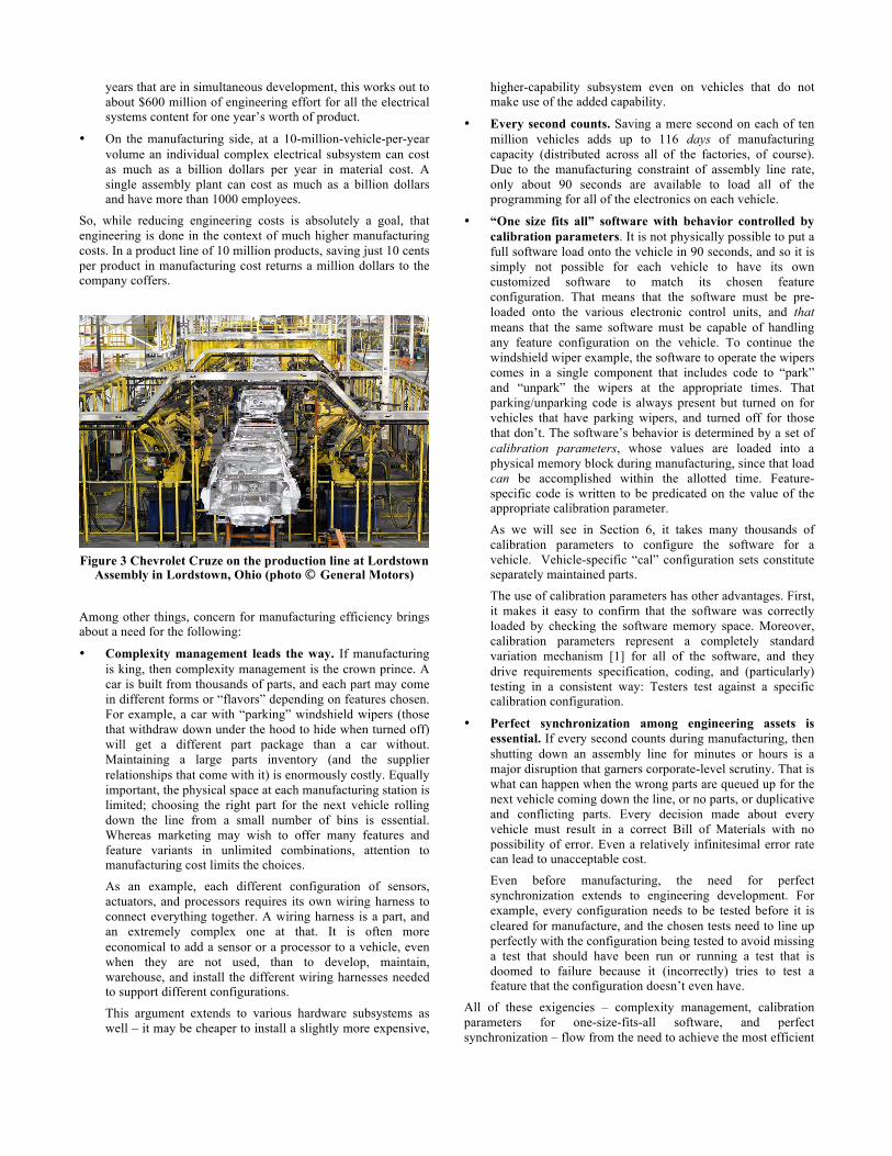
Figure 3 Chevrolet Cruze on the production line at Lordstown
Assembly in Lordstown, Ohio (photo © General Motors)
Among other things, concern for manufacturing efficiency brings about a need for the following:
• Complexity management leads the way. If manufacturing is king, then complexity management is the crown prince. A car is built from thousands of parts, and each part may come in different forms or “flavors” depending on features chosen. For example, a car with “parking” windshield wipers (those that withdraw down under the hood to hide when turned off) will get a different part package than a car without. Maintaining a large parts inventory (and the supplier relationships that come with it) is enormously costly. Equally important, the physical space at each manufacturing station is limited; choosing the right part for the next vehicle rolling down the line from a small number of bins is essential. Whereas marketing may wish to offer many features and feature variants in unlimited combinations, attention to manufacturing cost limits the choices.
As an example, each different configuration of sensors, actuators, and processors requires its own wiring harness to connect everything together. A wiring harness is a part, and an extremely complex one at that. It is often more economical to add a sensor or a processor to a vehicle, even when they are not used, than to develop, maintain, warehouse, and install the different wiring harnesses needed to support different configurations.
This argument extends to various hardware subsystems as well – it may be cheaper to install a slightly more expensive,
higher-capability subsystem even on vehicles that do not make use of the added capability.
• Every second counts. Saving a mere second on each of ten million vehicles adds up to 116 days of manufacturing capacity (distributed across all of the factories, of course). Due to the manufacturing constraint of assembly line rate, only about 90 seconds are available to load all of the programming for all of the electronics on each vehicle.
• “One size fits all” software with behavior controlled by calibration parameters. It is not physically possible to put a full software load onto the vehicle in 90 seconds, and so it is simply not possible for each vehicle to have its own customized software to match its chosen feature configuration. That means that the software must be pre-loaded onto the various electronic control units, and that means that the same software must be capable of handling any feature configuration on the vehicle. To continue the windshield wiper example, the software to operate the wipers comes in a single component that includes code to “park” and “unpark” the wipers at the appropriate times. That parking/unparking code is always present but turned on for vehicles that have parking wipers, and turned off for those that don’t. The software’s behavior is determined by a set of calibration parameters, whose values are loaded into a physical memory block during manufacturing, since that load can be accomplished within the allotted time. Feature-specific code is written to be predicated on the value of the appropriate calibration parameter.
As we will see in Section 6, it takes many thousands of calibration parameters to configure the software for a vehicle. Vehicle-specific “cal” configuration sets constitute separately maintained parts.
The use of calibration parameters has other advantages. First, it makes it easy to confirm that the software was correctly loaded by checking the software memory space. Moreover, calibration parameters represent a completely standard variation mechanism [1] for all of the software, and they drive requirements specification, coding, and (particularly) testing in a consistent way: Testers test against a specific calibration configuration.
• Perfect synchronization among engineering assets is essential. If every second counts during manufacturing, then shutting down an assembly line for minutes or hours is a major disruption that garners corporate-level scrutiny. That is what can happen when the wrong parts are queued up for the next vehicle coming down the line, or no parts, or duplicative and conflicting parts. Every decision made about every vehicle must result in a correct Bill of Materials with no possibility of error. Even a relatively infinitesimal error rate can lead to unacceptable cost.
Even before manufacturing, the need for perfect synchronization extends to engineering development. For example, every configuration needs to be tested before it is cleared for manufacture, and the chosen tests need to line up perfectly with the configuration being tested to avoid missing a test that should have been run or running a test that is doomed to failure because it (incorrectly) tries to test a feature that the configuration doesn’t even have.
All of these exigencies – complexity management, calibration parameters for one-size-fits-all software, and perfect synchronization – flow from the need to achieve the most efficient

manufacturing possible, which in turn flows from the extraordinarily high number of richly varying product instances.
Concurrent development streams. Because of the complexity of the products, designing a car for a model year must begin years in advance. In addition, products come out on an unforgiving yearly schedule. Therefore, each vehicle family has to be planned and developed taken though a years-long series of gates from concept and feasibility studies, to commitment to manufacture, to final design and parts selection, to the factory floor. GM may have up to 15 development streams in process simultaneously. To say that configuration management “takes on a special significance in the product line context” [13] is, in this setting, rather an understatement. Every piece of work must be correct for the product line’s current “cadence” (development stage) and coordinate and synchronize correctly with earlier and later cadences. Because all of the product line’s shared assets also have to be in sync with each other in each cadence, branching and merging are large-scale development events.
Distributed engineering means modularized feature models. For PLE to work at large organizations, it would be impractical to have a single organizational unit tasked with the care and feeding of the shared PLE assets. Certainly having one global collection of feature declarations for an entire production line is out of the question. System engineers have no interest or need to see all of the feature diversity in other systems. For example, engineers for an automotive transmission system do not need to see feature abstractions that capture the diversity in the entertainment or GPS navigation system. It makes no sense to comingle them. It makes much more sense to modularize the feature model in a way that corresponds to the organizational structure of the enterprise, in which domain knowledge is collated into groups that correspond to the vehicle’s systems.
Globally distributed engineering. To serve a worldwide market and save on shipping and distribution, factories are located around the globe to be close to customer segments. Engineering centers are also located around the world, with each given a specific area of responsibility. Thus, there is a critical need to keep the 5,000 or so product line engineers in sync in a number of ways.
First, training is required to keep the engineers on the same page concerning the product line engineering approach, the systems and software development tools chosen, the CM approach being utilized, and more. GM has a broad training curriculum. For example, as a prelude to working in the PLE enabled requirements tool chain, engineers are asked to take the following courses that range in duration from a few hours to a whole day:
• Requirements Management Engineering and Product Line Engineering Overview
• Introduction To DOORS (the requirements engineering tool from IBM Rational)
• Requirements Engineering with DOORS
• Product Line Engineering with Gears (the PLE feature modeling tool and configurator from BigLever Software)
• Managing Requirements Variation with Gears
• Configuration Management in DOORS
• Change Management with Rational Team Concert.
In addition to training, GM holds mentoring workshops throughout the various system groups where experts explain the best practices in (for example) feature modeling for a product line. Technical leaders from each system area attend these workshops,
and then mentor and teach their own teams. To date, there have been over 60 full-day feature modeling workshops held across the company; more are scheduled.
Second, everyone’s work, no matter where it is carried out, needs to be compatible with the rest of the product line. General Motors, like many global companies, faces the challenge of coordinating the activities of engineers located in different time zones and different continents. Multi-level variation: General Motors, through its product line approach, is in the process of standing a long-held automotive paradigm on its head: Rather than derive the features you can support on a vehicle by first choosing the type and capability of its parts, GM is choosing to derive the parts needed from a choice of features. Features play a first-class role; all else follows. Feature models are producing a GM-wide feature catalog that the designer of a vehicle family can use to create a “Bill-of-Features,” which can then be used to derive all of the engineering assets for that family, including the Bill of Materials.
To handle the variation complexity and account for the different kinds of engineering decisions that need to be made by people with different expertise, this process of vehicle definition can be usefully divided into a number of phases. Each phase involves a set of decisions; subsequent phases make more detailed decisions based on those from the previous phase(s). GM’s layered variation scheme is described here.
First, vehicle designers choose the Features1 they want a vehicle family to have. For example, the front seat climate control Feature for a vehicle can come in many flavors, as shown in the example feature model of Figure 42.
Engineering teams determine the specific set of feature combinations (called feature profiles) that they want to offer to the vehicle – these combinations correspond to the system configurations that have been developed and tested.
Figure 5 and Figure 6 show two such offerings (feature profiles) for a front seat climate control Feature. The first is a high-end offering, with automatic (meaning that the system maintains a set temperature) dual-zone (meaning there are separate controls for the passenger as well as the driver) dual-mode (meaning the passenger can control temperature and mode) for both heating and cooling. The other is a low-end profile, essentially offering ventilation only, that might be chosen for an entry-level vehicle in an emerging market.
After Feature decisions are made, vehicle designers then choose the packages of technology they want to put on the vehicle to support those Features. A technology package typically consists of sensors and/or actuators to effect some observable behavior in support of one or more Features. These technology packages are called subsystems, and they have variation as well.
The front seat climate control Feature can be provided by many different subsystem flavors, which vary by fans, sensors, 1 A Feature (with upper-case “F”) refers to a distinguishing characteristic
of a vehicle that is nominally visible to a customer and may well be used to market the vehicle. This is in contrast to a feature (lower-case “f”) which is a purely PLE construct, as in “feature modeling.” There are feature models to describe Features and, as we shall see, feature models to describe aspects of a vehicle that are not Features.
2 In this feature modeling language, features have types. An enumerated type obligates us to choose exactly one of its children; a set type allows us to choose zero, any, or all of its children. An atom type signifies a node that cannot be further elaborated.
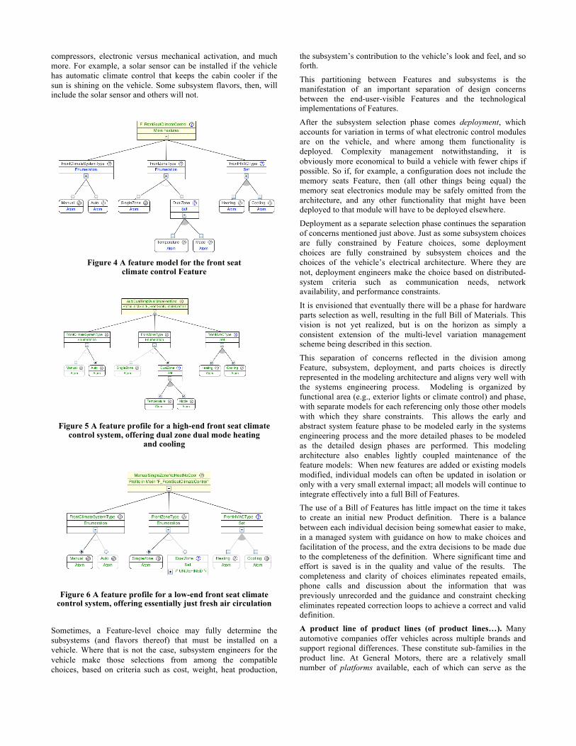
compressors, electronic versus mechanical activation, and much more. For example, a solar sensor can be installed if the vehicle has automatic climate control that keeps the cabin cooler if the sun is shining on the vehicle. Some subsystem flavors, then, will include the solar sensor and others will not.
Figure 4 A feature model for the front seat
climate control Feature
Figure 5 A feature profile for a high-end front seat climate
control system, offering dual zone dual mode heating and cooling
Figure 6 A feature profile for a low-end front seat climate
control system, offering essentially just fresh air circulation
Sometimes, a Feature-level choice may fully determine the subsystems (and flavors thereof) that must be installed on a vehicle. Where that is not the case, subsystem engineers for the vehicle make those selections from among the compatible choices, based on criteria such as cost, weight, heat production,
the subsystem’s contribution to the vehicle’s look and feel, and so forth.
This partitioning between Features and subsystems is the manifestation of an important separation of design concerns between the end-user-visible Features and the technological implementations of Features.
After the subsystem selection phase comes deployment, which accounts for variation in terms of what electronic control modules are on the vehicle, and where among them functionality is deployed. Complexity management notwithstanding, it is obviously more economical to build a vehicle with fewer chips if possible. So if, for example, a configuration does not include the memory seats Feature, then (all other things being equal) the memory seat electronics module may be safely omitted from the architecture, and any other functionality that might have been deployed to that module will have to be deployed elsewhere.
Deployment as a separate selection phase continues the separation of concerns mentioned just above. Just as some subsystem choices are fully constrained by Feature choices, some deployment choices are fully constrained by subsystem choices and the choices of the vehicle’s electrical architecture. Where they are not, deployment engineers make the choice based on distributed-system criteria such as communication needs, network availability, and performance constraints.
It is envisioned that eventually there will be a phase for hardware parts selection as well, resulting in the full Bill of Materials. This vision is not yet realized, but is on the horizon as simply a consistent extension of the multi-level variation management scheme being described in this section.
This separation of concerns reflected in the division among Feature, subsystem, deployment, and parts choices is directly represented in the modeling architecture and aligns very well with the systems engineering process. Modeling is organized by functional area (e.g., exterior lights or climate control) and phase, with separate models for each referencing only those other models with which they share constraints. This allows the early and abstract system feature phase to be modeled early in the systems engineering process and the more detailed phases to be modeled as the detailed design phases are performed. This modeling architecture also enables lightly coupled maintenance of the feature models: When new features are added or existing models modified, individual models can often be updated in isolation or only with a very small external impact; all models will continue to integrate effectively into a full Bill of Features. The use of a Bill of Features has little impact on the time it takes to create an initial new Product definition. There is a balance between each individual decision being somewhat easier to make, in a managed system with guidance on how to make choices and facilitation of the process, and the extra decisions to be made due to the completeness of the definition. Where significant time and effort is saved is in the quality and value of the results. The completeness and clarity of choices eliminates repeated emails, phone calls and discussion about the information that was previously unrecorded and the guidance and constraint checking eliminates repeated correction loops to achieve a correct and valid definition. A product line of product lines (of product lines…). Many automotive companies offer vehicles across multiple brands and support regional differences. These constitute sub-families in the product line. At General Motors, there are a relatively small number of platforms available, each of which can serve as the

design and manufacturing foundation. For example, a platform might define a common chassis and major mechanical components for a family of vehicles. And vehicle families have sub-families. For example, the same GM platform underlies its GMC Yukon, Chevrolet Tahoe, and Cadillac Escalade family of sport utility vehicles, as well as long wheel base utility vehicles and pick-up trucks. Each platform, then, defines a product line within the overall GM product line.
Each of these product lines is further differentiated to be sold in different regions of the world (and thus accommodate the regulatory and marketing differences in those regions). For example, there may be an Escalade family for China and another for North America – each its own product line within the platform product line. Within each one of those families are more sub-families offering low-end to high-end trim levels – still more product lines.
This product-line-of-product-lines approach defines a product family tree. At GM, platforms populate the top layer, with brand, regional, and trim level variations cascading down. So, where we spoke of “vehicle designers” in the previous section, we should more accurately have spoken of “vehicle family designers.” Defining a vehicle, then, becomes a matter of making choices at each level. All high-trim-level Buick Veranos destined for the US, for example, have a number of things in common with each other – they use the same platform, they conform to US regulations, and have many Feature and subsystem choices in common to give the Verano a distinctive look and feel.
Choices might be positive (e.g., all Veranos have this air conditioning system) or might be “down-selection” choices (a Verano might have any of three high-end infotainment systems but they will never have any of the four low-end ones.)
But there is still variation among this well-specified sub-family: options remain that can be chosen by dealers or end customers. The end customer orders a vehicle in their desired configuration; an assembly plant needs to be able to build any orderable configuration. The options that remain will, in most cases, still allow for too many variants to be defined than can be manufactured, and so (again invoking complexity management) the remaining variation is bundled into option packages to reduce the number of orderable configurations.
Constraint management: Complexity management, mentioned previously, deals with restricting the set of legal configurations to a manageable set that can be manufactured profitably. However, even before complexity management has a chance to whittle down the set, a comprehensive set of constraints has to eliminate the countless illegal configurations. Large-scale automotive manufacturing has been going on for about a century, with electronics and software for decades, but new features are driving inter-system complexity at a never-before-seen scale. Not long ago brakes and steering (for example) had little, if anything, to do with each other. Now, however, there are Features such as driver aids that keep you in your lane and prevent you from running into obstacles that integrate both, along with sensors to detect the outside world and displays to let the driver know what is going on. These separate systems are subject to complex interaction constraints that must be captured as constraints.
Constraints, which are expressed in terms of feature combinations, capture regulatory as well as technological realities. For example, daytime running lights are illegal in Japan, and so on any car whose region of sale (the options for which are captured in a
feature model) includes Japan, the daytime running lights Feature must be omitted. By contrast, daytime running lights are legally required in northern Europe – another constraint. Similarly, it is not technologically feasible to put a sunroof in a soft-top convertible, and so a mutual exclusion constraint between these two Features is captured. If a Feature is included in a configuration then the subsystem(s) necessary to support it must also be included. For example, an obstacle avoidance Feature requires a flavor of the brake system to be on the vehicle that can respond to software commands, and a subsystem (and flavor thereof) that provides the necessary obstacle-detecting sensors. Conversely, a subsystem should be omitted if none of the Features it supports have been selected for a vehicle.
These Feature/subsystem pairing requirements can also be captured as constraints. Figure 7 shows an example of this from the front seat climate control domain.
Experience at GM shows that about 30-35% of the time it takes to build a feature model is devoted to capturing constraints among features. This activity captures “tribal knowledge” that is often only in the heads of experienced engineers, who (like all people) are subject to retirement or better job offers elsewhere. Before putting these constraints in a formal feature model, engineers for a particular system spent a considerable amount of time answering questions, often asked over and over again, about which features their system was (and was not) compatible with. Now the models can be consulted instead.
Figure 7 A logic editor showing assertions for subsystem
flavors that need to be present to support Feature choices for front seat climate control. This editor uses prefix notation to express logical predicates. Guidelines (comments that explain
the constraints) are in purple.
Summary. The three overriding aspects of the automotive domain described in Section 2 (large numbers of products, complex products, and complex variation) have a number of strong implications for automotive PLE. These include:
• The overriding need to drive down manufacturing cost
• One-size-fits-all software
• Calibration parameters as the software variation mechanism
• Complexity management (reducing the number of configurations possible)
• Perfect synchronization of all stages of the lifecycle, from feature choices through manufacturing
• Attention to expressing and enforcing complex constraints among features
• Concurrent development streams
• Global development

• Multi-level phased variation choices (in GM’s case, variation chosen for Features, subsystems, deployment, and more)
• Product lines of product lines We posit that most, if not all, of these aspects will be found in any comparably large automotive product line. GM is taking the additional step of opting to derive parts from feature choices instead of the other way around.
4. Implications for PLE automated support Section 3 listed a number of conclusions about PLE for the automotive domain, using General Motors’ product line as the driving case, based on the three observations from Section 2 about mega-scale product lines. This section focuses specifically on the implications for PLE automated support.
As we noted in the previous section, product line engineering for automotive electronics has been going on for decades. But what’s new is the almost unfettered interaction among the many systems that populate a modern vehicle. Keeping track of the variation in each system and the feature interactions among systems now leads to too many possible combinations to mange by hand or with ad hoc methods. The labor is too demanding and the chance of making mistakes too great.
Given that automation is part of the automotive PLE approach, what must it do? The list includes the following:
• Feature modeling. There must be a concise, consistent way to model features across the enterprise, and so the tooling must provide a useful, easy-to-learn feature modeling language with enough richness to capture the kinds of variation seen in the automotive domain.
Put another way, the tooling must provide a single source of truth for features. The pressing need for perfect synchronization among all phases of engineering means that there must be a single source of truth for features, because they cross-cut every aspect of the engineering lifecycle: requirements, designs, code, calibrations, tests, network analysis, and more.
Moreover, since many separate groups are involved, often globally distributed, the feature language must include constructs for integrating separately developed feature models together. Having hundreds of separate engineering teams collaborate to build a single, gigantic, monolithic feature model is untenable. Flores et al. [6] describes the feature language in use at General Motors, including the constructs the language provides for integrating separately-developed feature models and representing product lines of product lines.
• Constraint support. Not only must the tool’s feature modeling language be rich enough to express the many kinds of constraints found in the automotive realm (as for the example shown in Figure 7), it must help enforce them as well. Vehicle family designers may make well over a thousand decisions in the course of bringing a line to market, and every one of those decisions must be in accordance with every one of the applicable constraints. The tooling must provide a way to guide the vehicle family designers in their task by, for example, presenting the set of constraint-compliant choices that are currently available, given previous choices already made. Without such automated support, engineering teams for the various systems can continue to expect phone calls, texts,
and e-mails asking whether a particular system variant can be put on a particular vehicle. With that automated support, the vehicle family designers can immediately see the choices that are available and the ones that are not. For the latter, they see what constraints those choices would violate.
Figure 8 shows a tool that helps vehicle family designers make their Feature and subsystem selections. The designer has just chosen the “AutoDualTempHeatCool” flavor of the front seat climate control Feature. The tool presents an engineer-authored guideline explaining what the option entails; the upper right window confirms that no constraints (called “assertions” here) are violated by this choice.
• Consistent variation management in artifacts across the full engineering lifecycle. For each vehicle family, requirements, system architectures and designs, code, test cases, documentation, calibration parameter sets, deployment decisions, parts lists, and more all need to line up. In the language of the SEI’s Framework for Product Line Practice [13], “Product builders use the [shared] assets… to produce products that meet their respective requirements.” A product means all of the engineering lifecycle artifacts just mentioned, instantiated to reflect the vehicle family being produced.
Figure 8 A selection "wizard" that helps vehicle family
designers make Feature and subsystem choices in compliance with feature constraints
A complete systems and software PLE lifecycle solution requires that all of these artifacts are endowed with variation points [1], which can be exercised to correspond to feature choices to produce demonstrably consistent instances specific to each vehicle or vehicle family, as desired.
Common representation of variation points is key to achieving traceability from requirements to deployment. Traceability is of great concern for GM. Every requirement needs to be traceable to one or more design elements that satisfy it, and each design element should be traceable back to one or more requirements that it satisfies. Each design element needs to be traceable forward to its implementation and vice versa. Each requirement needs to be traceable to one or more test cases that validate whether or not the requirement is satisfied in the final product. Managing all of these artifacts consistently, by tying their variations to the single source of feature truth, is the key to achieving this.

Figure 9 Feature profiles drive the exercising of shared assets’
variation points by the configurator to produce product-specific instances.
Figure 9 illustrates the concept. A configurator (in GM’s case, Gears [2]) exercises variation points in the shared assets. The shared assets contain variation points. A variation point is simply a place in a shared asset that needs to differ based on what feature it is supporting. Variation points are thus expressed in terms of features. Feature profiles (which reflect feature selections) are used by the configurator to exercise the variation points, to produce a feature-consistent set of product-specific asset instances. Thus, the automation should provide a consistent language and mechanisms for expressing variation points across all lifecycle artifacts.
• Lifecycle-wide integration. A large automotive company will have made tooling choices for each of these artifacts. In GM’s case, requirements are stored in IBM Rational’s DOORS tool, design models in Rhapsody, and so forth. To produce the instantiations, the PLE tooling has to work with each of these tools and preserve the traceability that exists among the artifacts stored in them.
• Multistage configuration. To support the product line of product lines approach, the tooling has to enable making some vehicle-level decisions while intentionally deferring others until lower in the hierarchy. For instance, for a platform we may be able to bind many platform-level choices: the number of doors and seats, for example. But many other choices will be left wide open for now. For a vehicle family, we may be able to make more choices or rule out other choices. For example, some propulsion systems may be allowed while others will be disallowed. For a particular vehicle family destined for a particular region with a particular trim level, we may be able to make most of the choices, but still leave other choices unbound and presented as options to the end consumers. In a product family tree, each node inherits the choices made by its ancestor nodes. Thus, as we descend down a path through the tree, we encounter a monotonically increasing amount of feature selection. This concept that combines staged decision-making, feature down-selection (ruling out choices) as well as making positive choices, and inheriting the decisions of a node’s ancestors, is called multistage configuration [8].
• Keeping options optional: Auto-proliferation. Automotive customers order their vehicles in their desired configurations,
choosing from available options and option packages. An assembly plant needs to build any orderable configuration. Complexity management dictates that not all possible combinations are orderable. Therefore, special manufacturing feature declarations exist to align the developed and released engineering content with the valid orderable configurations. These manufacturing features are never fixed in the product definition. They are by definition optional. No vehicle family designer ever fully binds the variation present in the lowest-levels of the product family tree. Their job is done when they have taken the variation down to the point when they are willing to provide any of the remaining combinations to their customers. These remaining combinations show up as customer-selectable option packages. And yet, factories need to manufacture specific vehicles in specific configurations in which all variation is bound. And so it is left to the tooling to bridge the gap between the variation intentionally left in by the engineers and a fully-defined vehicle that is manufactured.
To address this, GM’s PLE tools have a new auto-proliferation capability to automatically generate the fully proliferated set of feature combination for each valid orderable combination. This allows the product definers to operate in the language of options while still providing the precise complete definitions needed for engineering, release, and manufacturing.
• Industrial strength. Automation to support PLE at this scale needs to have a solid industrial pedigree. It also needs to be backed by an organization that has a responsive support group to quickly address any issues, an education and training department to helps the thousands of PLE engineers learn the technology and best practices in using it, and an evolution roadmap that will address the automaker’s future PLE needs.
5. New opportunities for engineering efficiencies Sections 2 through 4 have laid out the landscape of automotive PLE and shown how the exigencies of this particular domain lead to a demanding set of needs for the PLE approach and its supporting automation. In particular, the paradigm of Figure 9 emerged to provide the necessary lifecycle-wide integration of diverse kinds of shared assets, all with consistently-expressed and consistently-exercised feature-based variation points, to meet the need for perfect synchronization through engineering and into manufacturing. The PLE tooling (in GM’s case, Gears [2]), in addition to handling the configurator duties, also provides the feature modeling language. It allows separately developed feature models to be expressed and integrated. It also supports expressing a full range of feature-based constraints, provides multi-level variation support for designing vehicle families while enforcing those constraints. Finally, it provides multistage configuration, as well as auto-proliferation.
One very salient property of the paradigm of Figure 9 is that it is intentionally agnostic with respect to shared asset type. It uses the same basic variation language for all kinds of shared assets, manages traceability links among assets in a correct and consistent way, and expresses variation points in all assets in terms of features, not in terms of asset-specific or product-specific constructs.

This property immediately suggests the question, “What other shared assets can be profitably added to the picture?” By “profitably” we include the possibilities of faster engineering with more automation, reducing errors, and leading to fewer people doing tedious jobs by hand.
The next section will describe one very useful result of asking that question.
6. Automating the Configuration of Calibration Parameters Calibration parameters were mentioned in Section 3 as fallout from the fact that vehicle-specific software cannot be loaded in the allotted time for manufacturing. A GM internal case study on the software running on a particularly complex processor identified 3,206 calibration parameters associated with the software residing on that processor. When “proliferated” (that is, when generated in all possible variation combinations) for the customer-orderable combinations for one platform with one body style, 27,041 calibration decisions and 106 released calibration part numbers were required.
A company as large as GM can have more than 100 platform/body style combinations, resulting in more than 2.7 million decisions to calibrate one instance of the full product line – and that’s just for the software on one processor. For software on all processors across one instance of the product line, the total number of decisions required to support all orderable configurations could run to 50 million or more.
If it takes, on average, five minutes of engineering time to make one decision, this results in over 2,000 staff-years of effort. (Five minutes may seem too short for engineering decisions, but these decisions are not made from scratch each time. Procedures are developed to guide the decision process and most applications can be based off similar applications, but each decision still needs to be made and checked.)
That is the situation GM has been dealing with until now. Now, however, the automation inherent in their chosen PLE approach is presenting a new opportunity to make a dramatic impact on the cost of managing calibrations. First, some background: Calibrations come in two varieties:
• Configuration calibrations configure the controls to match the desired feature and build content of the vehicle. For example, if the vehicle has power seats, then the switches to control them are connected with discrete wires.
• Performance calibrations tune the desired features to the specific performance requirements for the vehicle; for example, how fast a seat moves when the switch is activated. Performance calibrations can be further divided.
o Deterministic performance calibrations have a value directly determined by the requirements. For example, the dome light should dim in 2 seconds.
o Experimental performance calibrations require an experimental procedure to determine the correct values. An example is the tuning of an anti-lock brake system for controlling wheel slip.
Traditionally, an engineering team creates calibration procedures that describe how to make each decision needed and “master” calibration sets to compare the result to. Master calibration sets cannot define each calibration value, but instead provide a comparison set and instructions for how to interpret differences between the master calibration and a developed calibration set.
Engineers then make the calibration decisions and perform reviews and comparisons before product validation provides a final confirmation of performance. For configuration calibrations the real engineering value lies in the creation of the instructions in the calibration procedures. If the instructions are accurate, the only source of error is a human misinterpretation of the instructions or requirements.
Adding calibration parameters as another type of shared asset in the PLE paradigm of Figure 9 can offer a much better alternative to these human-centric methods.
For configuration calibrations, instead of creating instructions for humans to read and master calibrations for calibration engineers to use, the engineering team renders the same instructions in tool-actionable variation logic for each calibration expressed in terms of the feature models for the product line. Because this logic will be acted on by tools, not humans, the double check method of a master calibration is no longer needed. When a Bill-of-Features for a product family is created, it can be used with the variation logic to generate all of the needed calibration sets. The product line tools can automatically generate the full valid manufactured feature proliferation for the product family and then generate a set of calibrations for each vehicle build combination. As the system is aware of the manufacturing variants, it can designate which calibration set is needed for each manufactured variant populating the release system.
This shifts the burden of calibration from one of engineering decisions and actions around every calibration to one with a more rigorous calibration procedure definition in the form of formal variation logic.
Figure 10 shows an excerpt of a requirements specification that defines the configuration calibration parameter called “Vehicle Propulsion Type.” This parameter should be given a value that corresponds to what kind of propulsion system is on the vehicle. When a vehicle instance is produced, the propulsion type feature will have a selected value, which will result in the correct variant being chosen here in the requirements. GM’s tooling chain will propagate this choice into design tools and eventually into the calibration set for that vehicle instance.
Figure 10 A variation point in requirements that, when
exercised, will result in the correct value being specified for the configuration calibration parameter.
A realistic estimate is that half of all of GM’s calibrations are configuration in nature and we can therefore eliminate almost half of the effort required to produce calibrations. In addition, errors detected by validation with the generated calibrations will now feed back as corrections in the precise variation models resulting in permanent corrections that are not subject to future human interpretation and error. Over time this can lead to true near-zero error rates in this half of the calibrations. The value of these improvements is measured in

hundreds to thousands of man/years per year, worth tens to hundreds of millions of dollars per year.
The benefits of this PLE-based approach to calibration do not stop here. While experimental performance calibrations require activities beyond what variation logic can provide, those activities themselves vary based on the features and vehicle configurations. The experiments needed to determine the performance calibrations are not always the same. Different feature combinations or different hardware configurations will require different experiments or different processing of results to generate the calibration values.
Traditionally, calibration engineers evaluate criteria in the calibration procedures to determine the correct experiments and needed analysis for each vehicle configuration. By using a PLE-enabled test management system, the test and analysis plan can be instrumented with variation points related to the feature models. A custom development plan can then be generated from the same Bill Of Features used for the configuration calibrations. While the savings from this integration are much smaller, this does eliminate a manual planning exercise and reduces the opportunity for errors and rework.
Continuing to ask “What other shared assets can be profitably added to the picture?” is bringing more opportunities into focus. As an additional example, variation points in design models can (when exercised for a vehicle family or instance) produce a catalog of data items that must flow over the vehicle’s networks. By generating a network data item catalog for each vehicle family, we should be able to more judiciously put networks on vehicles that adequately serve, but not over-serve, their needs and therefore further reduce costs. Finally, future work entails extending this feature-based PLE paradigm to manage variation in the product data management (PDM) as well as the product lifecycle management (PLM) and manufacturing phases of the enterprise.
7. Summary This paper has introduced the special exigencies of automotive engineering in a product line engineering context. The domain is characterized by a very large number of individually complex products with incomparably rich feature variation among them. These three aspects, taken by themselves and together, lead to a number of requirements on any PLE approach that hopes to work in this environment. We believe that this domain is well worth studying from a PLE perspective for at least three reasons:
• Demanding environments and large organizations require well-codified solutions that can be explained and taught – qualities any organization would find useful.
• The number of automotive PLE case studies seems to be surprisingly small.
• Showing PLE success in such a demanding domain can, we hope, be a boon for introducing PLE into any industry.
For example, GM’s practice of modeling (and then making choices from) Feature, subsystem, deployment, and part levels is, in our experience, unique to the automotive domain. We believe this is a useful separation of concerns that any product engineering organization could adopt, but might not know to do so except from reading narratives like this one. The notions of product family trees, multistage configuration, and auto-
proliferation are not unique to the automotive realm but, in our view, are under-represented in the PLE literature.
Even though GM has not yet finished the work of adding all of their desired shared assets to their PLE mix, they are already getting value out of their PLE efforts. Just defining an internally consistent model of their vehicle product line, structured as a family tree, with consistent configurations of Features, subsystems, components, and hardware allocations (all compliant with the thousands of intra- and inter-domain constraints in play) represents a very big step in managing the complexity at hand. To be able to do this in an end-to-end fashion under the auspices of fully interoperating tool suite is a capability not available at GM before now.
8. References [1] Bachmann, F., Clements, P., “Variability in Software
Product Lines,” Technical Report CMU/SEI-2005-TR-012, Software Engineering Institute, 2005.
[2] BigLever Software, “BigLever Software’s Product Line Engineering Solution,” http://www.biglever.com/solution/solution.html
[3] Clements, P., Gregg, S., Krueger, C., Lanman, J., Rivera, J., Scharadin, R., Shepherd, J., Winkler, A. “Second Generation Product Line Engineering Takes Hold in the DoD,” Crosstalk – The Journal of Defense Software Engineering, vol. 27, no. 1, January/February 2014.
[4] Clements, P.; Northrop, L. Software Product Lines: Practices and Patterns, Addison-Wesley, 2002.
[5] Dillon, M., Rivera, J., Darbin, R., Clinger, B., “Maximizing U.S. Army Return on Investment Utilizing Software Product-Line Approach,” Interservice/Industry Training, Simulation, and Education Conference (I/ITSEC), 2012.
[6] Flores, R., Krueger, C., Clements, P. “Mega-Scale Product Line Engineering at General Motors,” SPLC 2012, Salvador, Brazil, 2012.
[7] Jensen, Paul. (2009). “Experiences with Software Product Line Development.” CrossTalk 22, 1 (January 2009): 11–14.
[8] Krueger, C. “Multistage Configuration Trees for Managing Product Family Trees,” in Proceedings of the 17th International Software Product Line Conference (SPLC 2013), Tokyo, Japan, Aug. 2013.
[9] Krueger, C., Clements, P. “Systems and Software Product Line Engineering,” Encyclopedia of Software Engineering, Philip A. LaPlante ed., Taylor and Francis, 2013.
[10] Linden, Frank J. van der, Schmid, Klaus, Rommes, Eelco. Software Product Lines in Action, Springer, 2007.
[11] Paur, J. “Chevy Volt: King of (Software Cars),” Wired, November 5, 2010, http://www.wired.com/autopia/2010/ 11/chevy-volt-king-of-software-cars/
[12] Software Engineering Institute, “Catalog of Software Product Lines,” http://www.sei.cmu.edu/productlines/casestudies/catalog/index.cfm
[13] Software Engineering Institute, “Framework for Product Line Practice (Version 5.0)” http://www.sei.cmu.edu/ productlines/frame_report/index.html
[14] SPLC Product Line Hall of Fame, http://splc.net/fame.html
