how future-proof antenna systems help broadcasters in the u.s. television spectrum repack
TRANSCRIPT

© Radio Frequency Systems 2016 All rights reserved 1
Future-proof Antenna Systems
NAB Broadcast Engineering Conference 2016 Nick Wymant, CTO – Radio Frequency Systems
RADIO FREQUENCY SYSTEMS

© Radio Frequency Systems 2016 All rights reserved 2
Agenda:
• Introduction.
• Repack observations.
• Advanced antenna systems to facilitate the repack: Scenario 1.
• Future proof antenna systems for the repack and beyond: Scenario 2.
• Advanced master antenna systems to facilitate the repack: Scenario 3.
• Real World case studies.

© Radio Frequency Systems 2016 All rights reserved 3
RFS at a Glance
*
Revenues: 500 million
2100 Employees
7 Manufacturing centers
+250 Active patents
6 R&D centres
35 Sales and Technical
Support Offices

© Radio Frequency Systems 2016 All rights reserved 4
RFS Broadcast Production Sites
Meriden
U.S.A. Shanghai
China
São Paulo
Brazil
Melbourne
Australia
Hannover
Germany
Haddenham
United Kingdom

© Radio Frequency Systems 2016 All rights reserved 5
Broadcast Systems – Meriden Connecticut
• Located in Meriden, CT
• 20,000 ft2 indoor production space
allocated to broadcast.
• 76,000 ft2 outdoor broadcast test area.
• Engineering teams located on site.
• Sales team located on site.
• Far and near field test ranges on site.

© Radio Frequency Systems 2016 All rights reserved 6
Activities: Broadcast, Meriden Connecticut
• Pylon antenna design and manufacturing.
• Broadband slot antenna design and
manufacturing .
• Rigid line systems design and
manufacturing.
• Semi flexible cable manufacturing.
• Panel antennas integration and test .
• RF systems, mask filters and channel
combiners integration and test.

© Radio Frequency Systems 2016 All rights reserved 7
• 39 Month window.
• Coordinated effort or free-for-all?
• Number of qualified tower crews.
• Finite number of high power RF and
Structural Engineers.
• Limited coverage during operation on
interim antenna that can extend for a long
period of time.

© Radio Frequency Systems 2016 All rights reserved 8
• Delays to antenna work caused by weather are generally underestimated.
• Delay by one station can cause a domino effect, delaying multiple stations.
• The period of operation on an interim antenna was considerable in many
instances. 6-18 months in some cases. For this reason high performance
interim antenna solutions were adopted.
• The cost savings of re-using interim antenna systems was found to be
questionable when the removal and refurbishment costs are considered.
• Shared, broadband transmission capabilities were shown to provide for a
smooth transition, particularly when replicated at two sites.

© Radio Frequency Systems 2016 All rights reserved 9
Repack Scenario 1: Pylon Antenna Swap out
RADIO FREQUENCY SYSTEMS

© Radio Frequency Systems 2016 All rights reserved 10
This scenario is similar to Case #1 in the Widelity and Digital Tech Consulting reports.

© Radio Frequency Systems 2016 All rights reserved 11
© Radio Frequency Systems 2016 All rights reserved 12
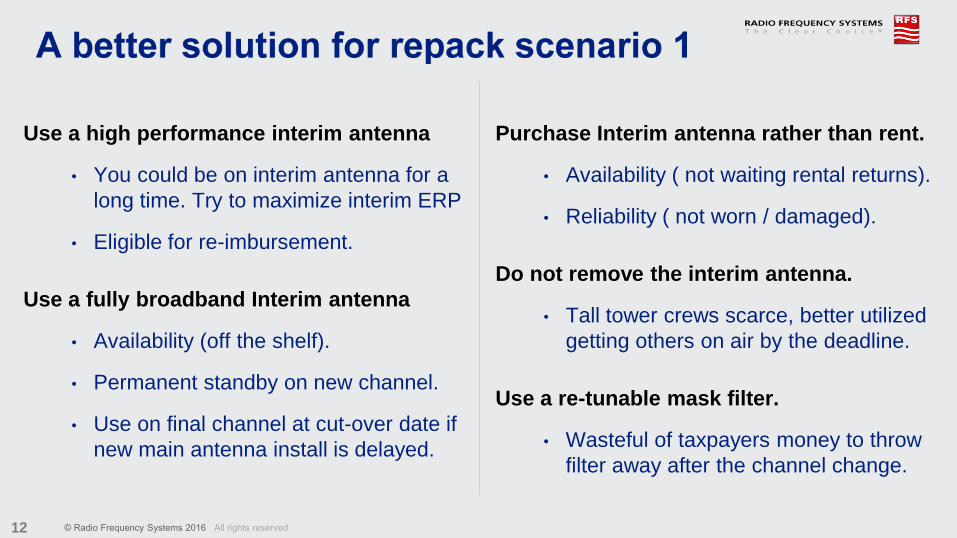
Use a high performance interim antenna
• You could be on interim antenna for a
long time. Try to maximize interim ERP
• Eligible for re-imbursement.
Use a fully broadband Interim antenna
• Availability (off the shelf).
• Permanent standby on new channel.
• Use on final channel at cut-over date if
new main antenna install is delayed.
Purchase Interim antenna rather than rent.
• Availability ( not waiting rental returns).
• Reliability ( not worn / damaged).
Do not remove the interim antenna.
• Tall tower crews scarce, better utilized
getting others on air by the deadline.
Use a re-tunable mask filter.
• Wasteful of taxpayers money to throw
filter away after the channel change.

© Radio Frequency Systems 2016 All rights reserved 13
Original scenario 1 Improved interim solution
Original ERP:
1000 kW
Interim ERP:
95 kW
Original ERP:
1000 kW
Interim ERP:
1000 kW

© Radio Frequency Systems 2016 All rights reserved 14
• Antennas that provide full band operation: 470-698 MHz.
• Low wind load: same or less than side mount pylon.
• Power handling to allow up to 2 x 1MW ERP’s.
• Elevation gain to allow full ERP with existing transmitters.
• Standard azimuth patterns to simplify FCC filing:
C-170, S-180, Ominoid.
• Re-tuneable high power mask filters, to allow re-use on post
repack channel.
• Mask filters that don’t require a specialist crew to re-tune.

© Radio Frequency Systems 2016 All rights reserved 15
Outcome: SBB Broadband Pylon Antenna
SBB-8 Broad-Band
Slot Antenna
Model SBB-8 SBB-16 SBB-24 SBB-32
Gain (C-170) 17 30 43 59
Max input power (kW)* 18 36 54 72
Typical ERP’s 340 kW 1 x 1MW 2 x 1MW 3 x 1MW
* Higher power option available

© Radio Frequency Systems 2016 All rights reserved 16
Production testing of SBB broadband pylons
SBB-8 measured VSWR

© Radio Frequency Systems 2016 All rights reserved 17
Production testing of SBB broadband pylons
SBB-8 measured radiation pattern C-170

© Radio Frequency Systems 2016 All rights reserved 18
6PPXX325E – 50 kW re-tunable UHF TV filter 1)
1) RFS tunable TE-101 mode resonator high-power filters first patented in 2014

© Radio Frequency Systems 2016 All rights reserved 19
Mask filter tuning software simplifies retune
S-parameters
BCAT
Tuning Actions Visualization of
tuning errors
Filter Library

© Radio Frequency Systems 2016 All rights reserved 20
Repack Scenario 2: Future proof equipment
RADIO FREQUENCY SYSTEMS

© Radio Frequency Systems 2016 All rights reserved 21

© Radio Frequency Systems 2016 All rights reserved 22
• Broadband antenna. Full UHF band operation: 470-698 MHz.
• Low wind load antenna: similar to top mount pylon and less than
stacked pylons.
• Power handling capability to allow at least to 2 full power stations
with elliptical or circular polarization.
• Ability to change polarization ratio in the future (VPT).
• Ability to add a second channel with independent polarization ratio.
• Re-tuneable / Broadband RF systems (mask, switch) - up to 100 kW.
• Re-tuneable channel combiners when a second channel is added. Broadband Cylinder
Antenna

© Radio Frequency Systems 2016 All rights reserved 23
Outcomes:
Range test of PEPL-28 antenna for
Dallas TX (half antenna under test)

© Radio Frequency Systems 2016 All rights reserved 24
Real World Example, Dallas TX:
Preparing PEPL-28 antenna for installation at Dallas site.

© Radio Frequency Systems 2016 All rights reserved 25
Dallas TX: Tunable 80kW + 80kW VPT Combiner
1)Patents granted
© Radio Frequency Systems 2016 All rights reserved 26
Repack Scenario 3: Master Antenna System
RADIO FREQUENCY SYSTEMS

© Radio Frequency Systems 2016 All rights reserved 27

© Radio Frequency Systems 2016 All rights reserved 28
• Full UHF band operation: 470-698 MHz.
• Power handling to allow multiple full power stations
with elliptical or circular polarization.
• Low wind load: less than existing panel antennas.
• Independent polarization ratio setting.
• Maintainable without removing antenna from the tower.
• Superior radiation pattern performance.

© Radio Frequency Systems 2016 All rights reserved 29
• Must be re-tuneable for repack and future channel changes.
• Must be adjacent channel capable.
• Must allow independent polarization control for each tenant.
• Power handling up to 100kW per input and up to 320kW total combined power.
• Compact and modular to minimize footprint and installation time.

© Radio Frequency Systems 2016 All rights reserved 30
Resulting products:
Example of a high power wrap
around antenna

© Radio Frequency Systems 2016 All rights reserved 31
VPT: How do we vary the polarization ratio ?
-450
Input +450
Input
Broadband pylon
+4
50 f
ee
der
Power splitter in TX room
TX
Cpol or Epol
-45
0 f
ee
der
A single channel VPT system.
• VPT utilizes dual input antennas.
• By changing the phase between inputs, the
desired polarization ratio can be achieved.

© Radio Frequency Systems 2016 All rights reserved 32
Multi-channel VPT systems
A channel combiner is used on each input.
TX’s have independent power splitters with phase
control => Independent polarization for each TX.
Future configuration: TX2 upgrades to a future
transmission standard that incorporates MIMO/MISO.
TX1 remains on the current standard.
-450 Combiner
+450 Combiner
TX1 TX2
-450
Feeder
+450
Feeder
Adjust Phase
Broadband pylon
-450
Antenna
Input
+450
Antenna
Input
-450 Combiner
+450 Combiner
TX1 TX2 data stream 1
-450
Feeder
+450
Feeder
Broadband pylon
-450
Antenna
Input
+450
Antenna
Input
TX1: ATSC
E-pol
TX2 data stream 2
TX2: Future standard
MIMO/MISO

© Radio Frequency Systems 2016 All rights reserved 33
Real World Case Study,
One World Trade, NYC

© Radio Frequency Systems 2016 All rights reserved 34
Case Study, One World Trade Center, NYC
UHF Upper Antenna
40 VPT panels.
VHF Antenna
16 VPT panels.
UHF Lower Antenna
96 VPT panels.

© Radio Frequency Systems 2016 All rights reserved 35
One World Trade Center, Trial antennas
* We wish to acknowledge the valuable assistance
of Dr Oded Bendov, Doug Lung and S. Merrill Weiss
during the antenna elevation pattern optimization
process.

© Radio Frequency Systems 2016 All rights reserved 36
Range Testing – One World Trade UHF Antenna 1
A section of the upper One World Trade UHF antenna
about to be lifted onto RFS far field test range A.
RFS far field test range A, one of
four broadcast outdoor antenna
ranges.
Disconnecting the lifting
equipment.

© Radio Frequency Systems 2016 All rights reserved 37
Range Testing – One World Trade VHF Antenna

© Radio Frequency Systems 2016 All rights reserved 38
VPT combiner design for
One World Trade Center
5-channel tunable TE-101 mode WG combiner
1)Patents granted
VPT combiner module ready for test

© Radio Frequency Systems 2016 All rights reserved 39
Tuneable Combiner Module with Waveguide Output
1)Patents granted and pending

© Radio Frequency Systems 2016 All rights reserved 40
Antennas and combiners were
designed with consideration of the
increased peak power requirement.
Ability to increase vertical polarization
component in the future to enhance
reception on hand held devices.
Mask filters designed with upgrade to
ATSC3 in mind.
Antennas ready for MIMO.

© Radio Frequency Systems 2016 All rights reserved 41
Conclusions
• Based on our experience with the UK and Australian repacks, RFS believe that broadband
frequency agile equipment provides the easiest path to a successful outcome.
• Weather and tower crew availability could delay installation of the main antenna. A high
performance broadband interim/reserve antenna that operates on pre and post restack
channels provides some insurance against operating at reduced ERP for a significant period of
time, or missing the switch-over date.
• Consider a re-tuneable interim mask filter that can be reused on the new channel allocation.
• Consider frequency agile and polarization agile solutions that provide a future upgrade path.
• Ensure that ATSC 3.0 operation has been considered during the design of any new equipment.
• Operation from a shared master site may prove to be the easiest way forward for many.

© Radio Frequency Systems 2016 All rights reserved 42
Thank You
Nick Wymant
CTO, RFS Broadcast
+1 (203) 707-8929

© Radio Frequency Systems 2016 All rights reserved 43
Follow us !
www.rfsworld.com