how to assemble a wood burning stove support...
TRANSCRIPT

HOW TO ASSEMBLE A WOOD BURNING STOVE SUPPORT DOCUMENT
ED KEANE 08/09/2013
HOW TO ASSEMBLE A WOOD BURNING STOVE
SUPPORT DOCUMENT (Supplement 2)
REFERENCE
HOW TO BUILD AN EFFICIENT WOOD BURNING STOVE
REVISION (A) 07/16/2013

HOW TO ASSEMBLE A WOOD BURNING STOVE SUPPORT DOCUMENT
ED KEANE 08/09/2013 Page 1
Introduction
This is supplement (2) to the reference document “How-to Build An Efficient Wood Burning
Stove” revision -A- 07/16/2013. This supplement (2) shows how to assemble the stove in the
reference document. The pictures are from a prototype stove built in North Carolina USA in
accordance with the reference document. This supplement (2) assumes the pieces needed to
assemble the stove are made in accordance with the reference document and supplement (1)
How to Make Pumice Bricks. Before assembling the stove a dimensionally check should be
made on the stove pieces to insure they are in accordance with the reference document. Another
check would be to assemble the stove dry see Figure 1. At this stage it easier to modify the
pieces so they fit.
Stove Support platform
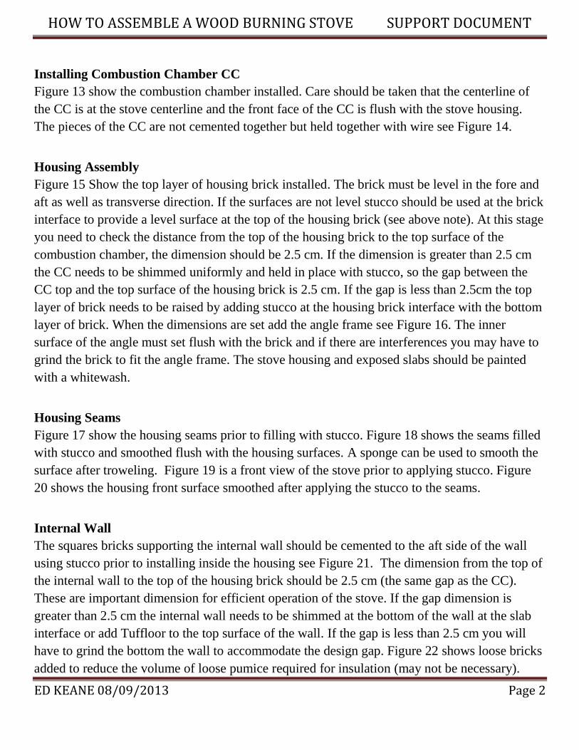
The stove support consists of a wood support frame and three pumice slabs stiffened with
bamboo. The overall stove arrangement drawing is shown in Figure 2.This drawing locates the
support slab relative to the wood frame. The slabs and wood support are symmetrical about the
centerline of the stove. To insure this is the case check that the slab overhang on both sides
should be equal. Figure 3 show the slabs receiving a stucco coating on the top and sides prior to
assembly. Figure 4 show the stucco mix (3 parts fine sand, one part lime and one part cement)
by volume. Other types of stucco mixes made locally can be used. Before assembling the
housing brick make sure the three slabs are level. If not level use the stucco coating to provide a
level surface see Figure 5. Figure 6 is a picture of stove support assembly. Figure 7 shows the
stove housing brick arrange to receive a stucco coating on the outer surfaces and Figure 8 shows
the consistency of the stucco mix. Figure 9 show the bricks with the stucco coating. Figure 10
show the markings for the stove centerline. For positioning of the pumice housing bricks on the
support slabs see Figure 11 and Figure 1 for the dimension. There is no need to cement the
bricks to the slab or each other. One centimeter diameter bead of stucco along the brick
centerline at the interface would surface. If the top of the bricks are not level, a layer of stucco
should be used to level the brick. It is important to check the brick level at every stage of
assembly see Figure 12
NOTE: The dimensions of the housing brick assume the gaps at the brick interface is zero.
Adding stucco to level the brick must be done with care and use only the amount necessary to
level the brick.
HOW TO ASSEMBLE A WOOD BURNING STOVE SUPPORT DOCUMENT
ED KEANE 08/09/2013 Page 2
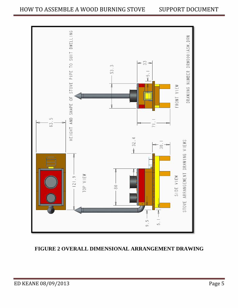
Installing Combustion Chamber CC
Figure 13 show the combustion chamber installed. Care should be taken that the centerline of
the CC is at the stove centerline and the front face of the CC is flush with the stove housing.
The pieces of the CC are not cemented together but held together with wire see Figure 14.
Housing Assembly
Figure 15 Show the top layer of housing brick installed. The brick must be level in the fore and
aft as well as transverse direction. If the surfaces are not level stucco should be used at the brick
interface to provide a level surface at the top of the housing brick (see above note). At this stage
you need to check the distance from the top of the housing brick to the top surface of the
combustion chamber, the dimension should be 2.5 cm. If the dimension is greater than 2.5 cm
the CC needs to be shimmed uniformly and held in place with stucco, so the gap between the
CC top and the top surface of the housing brick is 2.5 cm. If the gap is less than 2.5cm the top
layer of brick needs to be raised by adding stucco at the housing brick interface with the bottom
layer of brick. When the dimensions are set add the angle frame see Figure 16. The inner
surface of the angle must set flush with the brick and if there are interferences you may have to
grind the brick to fit the angle frame. The stove housing and exposed slabs should be painted
with a whitewash.
Housing Seams
Figure 17 show the housing seams prior to filling with stucco. Figure 18 shows the seams filled
with stucco and smoothed flush with the housing surfaces. A sponge can be used to smooth the
surface after troweling. Figure 19 is a front view of the stove prior to applying stucco. Figure
20 shows the housing front surface smoothed after applying the stucco to the seams.
Internal Wall
The squares bricks supporting the internal wall should be cemented to the aft side of the wall
using stucco prior to installing inside the housing see Figure 21. The dimension from the top of
the internal wall to the top of the housing brick should be 2.5 cm (the same gap as the CC).
These are important dimension for efficient operation of the stove. If the gap dimension is
greater than 2.5 cm the internal wall needs to be shimmed at the bottom of the wall at the slab
interface or add Tuffloor to the top surface of the wall. If the gap is less than 2.5 cm you will
have to grind the bottom the wall to accommodate the design gap. Figure 22 shows loose bricks
added to reduce the volume of loose pumice required for insulation (may not be necessary).

HOW TO ASSEMBLE A WOOD BURNING STOVE SUPPORT DOCUMENT
ED KEANE 08/09/2013 Page 3
Figure 23 show the loose pumice being added and Figure 24 show the final arrangement inside
the stove.
Stove Top Cooking Plate
For the stove top cooking steel plate see Figures 25 and 26. The cooking plate is .476 cm thick
with stiffeners. The perimeter stiffeners are 2.54 cm deep .64 cm wide and the internal
stiffeners are 1.27 cm square. The fabricated cooking plate should be centered, aligned and
flush with the top of the angle frame. The alignment can be done by making sure the gap
between the cooking plate and the angle frame is the same all the way around the perimeter of
the cooking plate. Coat all the steel with high temperature black paint or oil to prevent
corrosion. Save the cut out piece from the stove plate opening to manufacture the loose ring
used to accommodate a smaller pot see Figure 26.
The inner disk remaining from the ring manufacturing could be saved if there is a need to cover
the opening. To support the disk add three tabs equally spaced and welded to the underside of
the loose ring to support the disk. Make sure the tabs do not interfere with the support ring, so
the closure plate sits flush with the cooking plate
Chimney stove pipe
A wood stove cannot function properly without a good chimney arrangement that will create a
draft needed to remove the noxious gases from the home. The longer the stove pipe straight
section the better the draft. The best arrangement would be for the chimney to go straight
through the roof see Figure 28. Too much draft can be a problem because the chimney has no
damper to regulate the amount of draft and high draft can result in a fast burn, see Supplement
(3).
There is an advantage to keep the stove pipe in the house. If the outside temperature is colder
than the inside, there will be a reduction in draft. The stove pipe can reach a temperature of 270
degrees Celsius and it is a good idea to wrap a screen around the stove pipe in areas of human
contact. The size of the stove pipe is 10.16cm diameter black pipe or galvanized with a
thickness 22 to 28 gage whatever is available. You will need one 90 degree elbows and a rain
cap for the stove pipe that exits through the roof. You will need two elbows for the stove pipe
that goes through the wall. The length of straight section in both arrangements should be 1.5 to
2 meter. For a home with a thatch roof see Figures 28. The stove pipe should go through the
side wall with a metal cover to protect the thatch roof from sparks that could cause a fire.
Brackets should be provided to support the stove pipe and they need to have the design feature

HOW TO ASSEMBLE A WOOD BURNING STOVE SUPPORT DOCUMENT
ED KEANE 08/09/2013 Page 4
to be disassembled for cleaning (removing creosote) . Figure 29 show a stove pipe connection
and Figure30 show a stove pipe extending through the roof with a typical rain cap.
Locating stove
If acceptable to the home owner, the stove should be place on the wall opposite the dominant
wind direction so the wind will take the chimney smoke away from the house and prevent the
wind from going down the chimney exhaust. Position the stove away from direct breeze or cold
air from entering the stove firewood feed. There may be very little choice in some homes but a
good location will make the stove function more efficiently.
.
FIGURE 1 STOVE ASSEMBLY DRY FOR CHECKING FIT-UP
HOW TO ASSEMBLE A WOOD BURNING STOVE SUPPORT DOCUMENT
ED KEANE 08/09/2013 Page 5
FIGURE 2 OVERALL DIMENSIONAL ARRANGEMENT DRAWING

HOW TO ASSEMBLE A WOOD BURNING STOVE SUPPORT DOCUMENT
ED KEANE 08/09/2013 Page 6
FIGURE 3 APPLING STUCCO TO TOP AND SIDE OF SUPPORT SLABS
FIGURE 4 DRY STUCCO MIX -(3) SAND-(1) LIME- (1)CEMENT

HOW TO ASSEMBLE A WOOD BURNING STOVE SUPPORT DOCUMENT
ED KEANE 08/09/2013 Page 7
FIGURE 5 LEVELING TOP OF SUPPORT SLABS WITH STUCCO
FIGURE 6 STOVE SUPPORT PLATFORM

HOW TO ASSEMBLE A WOOD BURNING STOVE SUPPORT DOCUMENT
ED KEANE 08/09/2013 Page 8
FIGURE 7 OUTSIDE OF HOUSING BRICKS
FIGURE 8 STUCCO CONSISTENCY

HOW TO ASSEMBLE A WOOD BURNING STOVE SUPPORT DOCUMENT
ED KEANE 08/09/2013 Page 9
FIGURE 9 HOUSING BRICKS WITH STUCCO FINISH
FIGURE 10 MARKING SLAB CENTERLINE

HOW TO ASSEMBLE A WOOD BURNING STOVE SUPPORT DOCUMENT
ED KEANE 08/09/2013 Page 10
FIGURE 11 MARKING HOUSING REAR WALL LOCATION
FIGURE 12 ASSEMBLY OF FIRST LAYER OF HOUSING BRICK
HOW TO ASSEMBLE A WOOD BURNING STOVE SUPPORT DOCUMENT
ED KEANE 08/09/2013 Page 11
FIGURE 13 LOCATING COMBUSTION CHAMBER CC
FIGURE 14 CC HELD TOGETHER WITH WIRE

HOW TO ASSEMBLE A WOOD BURNING STOVE SUPPORT DOCUMENT
ED KEANE 08/09/2013 Page 12
FIGURE 15 ASSEMBLY OF SECOND LAYER OF HOUSING BRICK
FIGURE 16 ASSEMBLY OF ANGLE FRAME TO TOP OF HOUSING

HOW TO ASSEMBLE A WOOD BURNING STOVE SUPPORT DOCUMENT
ED KEANE 08/09/2013 Page 13
FIGURE 17 STOVE SIDE VIEW SHOWING SEAMS
FIGURE 18 THE SEAMS COVERED WITH STUCCO

HOW TO ASSEMBLE A WOOD BURNING STOVE SUPPORT DOCUMENT
ED KEANE 08/09/2013 Page 14
FIGURE 19 FRONT VIEW OF STOVE HOUSING SHOWING SEAMS
FIGURE 20 SEAMS COVERED WITH STUCCO

HOW TO ASSEMBLE A WOOD BURNING STOVE SUPPORT DOCUMENT
ED KEANE 08/09/2013 Page 15
FIGURE 21 VIEW SHOWING THE ASSEMBLY WITH INTERNAL WALL
FIGURE 22 BRICKS CAN BE ADDED TO REDUCE THE AMOUNT OF PUMICE

HOW TO ASSEMBLE A WOOD BURNING STOVE SUPPORT DOCUMENT
ED KEANE 08/09/2013 Page 16
FIGURE 23 LOOSE PUMICE TO FILL CAVITY AROUND CC
FIGURE 24 FINAL ASSEMBLY WITH COOKING PLATE REMOVED

HOW TO ASSEMBLE A WOOD BURNING STOVE SUPPORT DOCUMENT
ED KEANE 08/09/2013 Page 17
FIGURE 25 BOTTOM VIEW OF COOKING PLATE SHOWING STIFFENERS
FIGURE 26 TOP VIEW OF COOKING PLATE SHOWING LOOSE RING

HOW TO ASSEMBLE A WOOD BURNING STOVE SUPPORT DOCUMENT
ED KEANE 08/09/2013 Page 18
FIGURE 27 FINAL ASSEMBLY OF PROTOTYPE STOVE-NOTE STOVE IMAGE-
FIGURE 28 VIEW SHOWING STOVE PIPE ARRANGEMENTS
THATCH ROOF
TIN PLATE
INSERT
TIN ROOF
FLASHING

HOW TO ASSEMBLE A WOOD BURNING STOVE SUPPORT DOCUMENT
ED KEANE 08/09/2013 Page 19
FIGURE 29 STOVE PIPE CONNECTION
FIGURE 30 STOVE PIPE EXTENDING THROUGH A TIN ROOF
HOW TO ASSEMBLE A WOOD BURNING STOVE SUPPORT DOCUMENT
ED KEANE 08/09/2013 Page 20
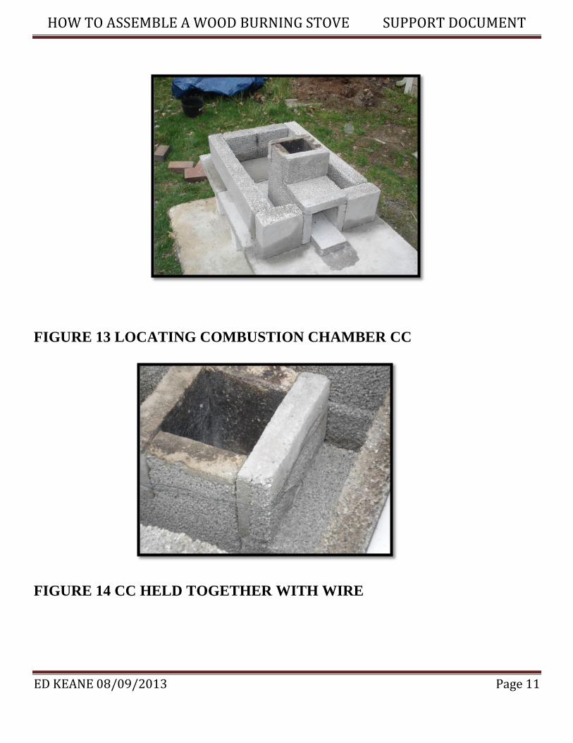
STOVE IMAGE
POPE JOHN PAUL II COAT OF ARMS –IMAGE OF MARIAN CROSS
THIS IMAGE WAS PLACE ON HIS WOODEN COFFIN
THIS WOULD BE A GOOD IMAGE TO PAINT ON THE SIDE OF THE
STOVE IN MEMORY OF POPE JOHN PAUL II