how to choose threading tool - geers · pdf filethreading how to choose threading tool b ......
TRANSCRIPT

C 2
THREADING How to choose threading tool
B
Gen
eral
Tur
ning
Par
ting
and
Gro
ovin
g
C
Thre
adin
g
G
Tool
ing
syst
ems
Mul
ti-ta
sk m
achi
ning
I
Cor
oTur
n® S
L
J
Gen
eral
info
rmat
ion
A
H
C
Thre
adin
g
THREADING How to choose threading tool
For more technical information, see our Metalcutting Technical guide
How to choose threading tool
1
2
3
4
5
External threading Coromant Capto® unit Inserts
Conversion table, formulas and definitions
Internal threading Shank holder Spare parts/accessories Grade descriptions
CoroTurn® SL internal adaptors Boring bar Sleeves Technical
information
Build-in tools Tooling system How to choose tool, overview
Tailor Made options
Define your type of operation
Select your method for threading page C4:
- External or internal threading- Right hand threads or left hand threads- Select the thread type
Select insert size, grade, geometry and type of infeed
Choose your pitch and size of insert. If possible choose a multi-point insert for better productivity.Choose your geometry, grade and type of infeed. Detailed recommendations on page C80
Select tooling system and type of holder
Choose Coromant Capto or shank tool, depending on clamping possibilities in turret/spindle,on page G5.Choose type of holder and coupling size or shank on page C7.The insert seat must correspond to the size of the insert.
Select suitable shim
Choose correct shim for your pitch/workpiece diameter. See page C45 for CoroThread 266 and page C57 for T-Max U-Lock.Shims are used to give different tilts to the insert and are available in 1° steps from -2° to +4° .Threading holders are supplied as standard with a shim giving +1° inclination angle.Note: No shims for smaller diameter bars as the angle is fixed at +2° .
Select size, number of passes and speed
The recommendations are intended as starting values. (Page C70)Cutting speed recommendations, page C82.
B
C 3
Gen
eral
Tur
ning
Par
ting
and
Gro
ovin
g
C
Thre
adin
g
G
Tool
ing
syst
ems
Mul
ti-ta
sk m
achi
ning
I
Cor
oTur
n® S
L
J
Gen
eral
info
rmat
ion
A
H
C
Thre
adin
g
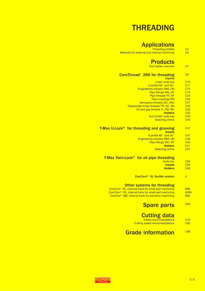
Content THREADING
THREADING Content
THREADING
ApplicationsThreading profiles C4
Methods for external and internal machining C6
ProductsTool holder overview C7
CoroThread® 266 for threading C9Inserts
Insert code key C10V-profile 60° and 55° C11
Engineering industry MM, UN C19Pipe fittings WH, NT C19Pipe threads PT, NF C24Pipe couplings RN C25
Aerospace threads MJ, UNJ C27Trapezoidal screw threads TR, AC, SA C30
Oil and gas threads V-, RD, BU C30Holders C35
Tool holder code key C35Selecting shims C45
T-Max U-Lock® for threading and grooving C47Inserts
V-profile 60° and 55° C47Engineering industry MM, UN C48
Pipe fittings WH, NT C50Holders C51
Selecting shims C57
T-Max Twin-Lock® for oil pipe threadingCode key C58
Inserts C59Holders C60
CoroTurn® SL flexible system I1
Other systems for threadingCoroCut® XS, external tools for small part machining B88CoroTurn® XS, internal tools for small part machining A309CoroCut® MB, internal tools for precision machining B95
Spare parts C63
Cutting dataInfeed recommendations C70
Cutting speed recommendations C82
Grade information C86
C 3

C 4
THREADING Choosing inserts and tools
B
Gen
eral
Tur
ning
Par
ting
and
Gro
ovin
g
C
Thre
adin
g
G
Tool
ing
syst
ems
Mul
ti-ta
sk m
achi
ning
I
Cor
oTur
n® S
L
J
Gen
eral
info
rmat
ion
A
H
C
Thre
adin
g
THREADING Choosing inserts and tools
Threading profiles
Thread type General usage for all segments of engineering industry.
Pipe fittings and couplings for gas, water and sewage.
Pipe threads for steam, gas and water lines
Page Page Page
CoroThread® 266 V-profile 60° VM C11 Whitworth 55° WH C19 BSPT 55° PT C22266R/LG External V-profile 55° VW C13 NPT 60° NT C21 NPTF 60° NF C23266R/LL Internal Metric 60° MM C14
UN 60° UN C17
T-Max® U-Lock V-profile 60° VM C47 Whitworth 55° WH C50R/L166.0L Internal V-profile 55° VW C47 NPT 60° NT C50
Metric 60° MM C48UN 60° UN C49
T-Max Twin-Lock®R/L166.39G ExternalR/L166.39L Internal
CoroCut® XS V-profile 60° B93External
MATR/L
CoroTurn® XS V-profile 60° VM A322 Whitworth 55° WH A322Internal Metric 60° MM A322 NPT 60° NT A322
UN 60° UN A322
CXS-
CoroCut® MBInternal V-profile 60° VM B103 Whitworth 55° WH B103
Metric 60° MM B103 NPT 60° NT B103
MB- UN 60° UN B103
All types of threadsCoroThread® 266
Ultra-rigid threading, insert sizes 16, 22 and 27
T-Max U-Lock®
Insert size 11

B
C 5
Gen
eral
Tur
ning
Par
ting
and
Gro
ovin
g
C
Thre
adin
g
G
Tool
ing
syst
ems
Mul
ti-ta
sk m
achi
ning
I
Cor
oTur
n® S
L
J
Gen
eral
info
rmat
ion
A
H
C
Thre
adin
g
Choosing inserts and tools THREADING
THREADING Choosing inserts and tools
Pipe couplings in food and fire fighting industries
Aerospace threads. Screw threads for motion transmissions
Oil and gas
Page Page Page Page
Round DIN 405 RN C24 MJ 60° MJ C25 ISO Trapezodial TR C27 API 60° V C30UNJ 60° NJ C26 ACME AC C28 RD C31
STUB-ACME SA C28 API Buttress BU C32
Casing and tubing
API Round Vee RD C59API Buttress BU C59
ISO Trapezodial TR A322
ACME AC C28STUB-ACME SA C29
T-Max Twin-Lock®Threading in oil and gas industry primarily casing and tubing
Small part machining CoroCut® XS for external and CoroTurn® XS for internal threadingCoroCut® MB for internal precision threading

C 6
THREADING Choosing inserts and tools
B
Gen
eral
Tur
ning
Par
ting
and
Gro
ovin
g
C
Thre
adin
g
G
Tool
ing
syst
ems
Mul
ti-ta
sk m
achi
ning
I
Cor
oTur
n® S
L
J
Gen
eral
info
rmat
ion
A
H
C
Thre
adin
g
THREADING Choosing inserts and tools
Selecting the method of thread cuttingThe machine tool and the design of the workpiece determine which method is to be used to cut a thread. Working towards the chuck is the most common method.
Working away from the chuck is also possible but when producing right hand threads with left hand tools and vice versa, compensation must be made for the negative helix angle by means of changing the shim.
The advantage of using right hand tools for right hand threads and lefthand tools for left hand threads is that the holder design is made to givemaximum suport to the insert.
Note that holder and insert of the same hand must be used together for the CoroThread and U-Lock programme.
Methods for external threading
Right hand threads Left hand threads
Right hand tools/inserts
Right hand tools/inserts
Left hand tools/inserts (negative helix angle)
Left hand tools/inserts
Left hand tools/inserts
Right hand tools/inserts (negative helix angle)
Pull threading Pull threading Pull threading Pull threading
Methods for internal threading
Right hand threads Left hand threads
Right hand tools/inserts
Left hand tools/inserts (negative helix angle)
Left hand tools/inserts Right hand tools/inserts (negative helix angle)
Pull threading Pull threading

B
C 7
Gen
eral
Tur
ning
Par
ting
and
Gro
ovin
g
C
Thre
adin
g
G
Tool
ing
syst
ems
Mul
ti-ta
sk m
achi
ning
I
Cor
oTur
n® S
L
J
Gen
eral
info
rmat
ion
A
H
C
Thre
adin
g
Choosing inserts and tools THREADING
THREADING Choosing inserts and tools
External threading and circlip grooving
General threading For swiss machines Threading of slender components and against live centre
To be used with CoroThread 266 inserts
CoroThread® CoroThread® CoroThread® T-Max® U-Lock T-Max® U-Lock266R/LFG 266R/LFG 266R/LFA R/L166.5FA R/L166.5FA
Insert size, mm (iC, inch)
16, 22, 27 (3/8, 1/2, 5/8) 16, 22, 27 (3/8, 1/2, 5/8) 16 (3/8) 16 (3/8) 16 (3/8)
Coromant Capto® sizes
C3-C8 – – C3-C6 –
Shank size, mm – 1616-4040 1010-1616 – 1212-2525
Shank size, inch – .750-1.500 .375-.750 – .500-1.250
Page C35 C36 C37 C51 C52
Drop head design for upside down mounting CoroThread® 266 SL- external cutting head
To be used with CoroThread 266 inserts
CoroThread® CoroThread® T-Max® U-Lock CoroThread®266R/LFGZ 266R/LFGZ R/L166.5FAZ SL-266R/LFG
Insert size, mm (iC, inch)
16, 22, 27 (3/8, 1/2, 5/8) 16, 22 (3/8, 1/2) 16 (3/8) 16 (3/8)
Coromant Capto® sizes
C4-C6 – C3-C6 –
Shank size, mm – 2525-3232 – –
Shank size, inch – .750-1.250 – –
Coupling size – – – 20-40
Page C35 C36 C51 I52
T-Max Twin-Lock® Small part machining
QS™ holding system
R166.39FG QS-266 RFA
Insert size, mm (inch) 24 (.945) 16 (3/8)
Shank size, mm 3232 1010-1616
Shank size, inch 1.260 .376-.825
Page C60 C38

C 8
THREADING Choosing inserts and tools
B
Gen
eral
Tur
ning
Par
ting
and
Gro
ovin
g
C
Thre
adin
g
G
Tool
ing
syst
ems
Mul
ti-ta
sk m
achi
ning
I
Cor
oTur
n® S
L
J
Gen
eral
info
rmat
ion
A
H
C
Thre
adin
g
THREADING Choosing inserts and tools
Internal threading and circlip grooving
Coromant Capto Carbide reinforced bars
Drop head design for upside down mounting
Cylindrical, cylindrical with flats
CoroThread® T-Max® U-Lock CoroThread® T-Max® U-Lock T-Max® U-Lock266R/LKF R/L166.0KF 266R/LKF R/L166.0KF R/L166.0KFZ
Insert size, mm (iC, inch) 16-22 (3/8-1/2) 11 (1/4) 16, 22, 27 (3/8, 1/2, 5/8) 11 (1/4) 11 (1/4)
Coromant Capto® sizes
C3-C6 C3-C4 – – C3-C4
Bar diameter, mm (inch)
– – 20-50 (.750-2.000) 10-16 (.625-.750) –
Page C39 C53 C41 C55 C53
SL cutting head Cartridges Cutting head for CoroTurn® SL quick change
CoroThread® T-Max® U-Lock CoroThread® CoroThread®
SL-266R/LKF R/L566.0KFC 266 SL-266RKF
Insert size, mm (iC, inch) 16, 22, 27 (3/8, 1/2, 5/8) 11 (3/4) 16, 22 (3/8, 1/2) 22, 27 (1/2, 5/8)
SL coupling size, mm 25-40 16-20 – 80
Cartridge size – – 16CA-20CA –
Page I53 I54 C44 I86
T-Max Twin-Lock® SL cutting head Cartridge T-Max P cartridge
T-Max Twin-Lock® T-Max Twin-Lock® T-Max Twin-Lock®R566.39KF 466.39 R466.3KW
Insert size, mm, (inch) 24 (.945) 24 (.945) 16 (3/8)
Coupling size, mm 40 - -
Cartridges size, mm (inch)
- 18 (.709) 20 (.787)
Page C60 C61 C62
For cylindrical sleeves, see page A304.

B
C 9
Gen
eral
Tur
ning
Par
ting
and
Gro
ovin
g
C
Thre
adin
g
G
Tool
ing
syst
ems
Mul
ti-ta
sk m
achi
ning
I
Cor
oTur
n® S
L
J
Gen
eral
info
rmat
ion
A
H
C
Thre
adin
g
CoroThread® 266 inserts THREADING
THREADING CoroThread® 266 inserts
CoroThread® 266Ultra rigid thread turning
For all types of threads
Insert sizes: 16, 22 and 27 mm(3/8, 1/2 and 5/8 inch)
- Full profile - for high productivity
- V-profile - for minimum tool inventory
- Multi-point - for economic threading in mass production
Easy clamping of new inserts on rail guide.
Grades for all materialsBasic grades GC1125
GC1135GC1020
Unique Tailor Made service
Enables you to order inserts for almost any thread form or pitch. See page J3
ISO application areas:
Insert sizes

C 10
THREADING CoroThread® 266 inserts
B
Gen
eral
Tur
ning
Par
ting
and
Gro
ovin
g
C
Thre
adin
g
G
Tool
ing
syst
ems
Mul
ti-ta
sk m
achi
ning
I
Cor
oTur
n® S
L
J
Gen
eral
info
rmat
ion
A
H
C
Thre
adin
g
THREADING CoroThread® 266 inserts
Code key for CoroThread® 266 inserts
1 Main code 2 Hand of tool 3 Type of machining 4 Insert size/dimension
266 = CoroThread 266 R = Right hand style G = Inserts for external threading 16 = iC 3/8’’ = 9.52 mm22 = iC 1/2’’ = 12.70 mm
L = Left hand style L = Inserts for internal threading 27 = iC 5/8’’ = 15.88 mm
5 Thread profile 6 Number of points per cutting edge
VM0 = V-profile 60° AC0 = ACME 29° Varies from 1 to 3 points.VW0 = V-Profile 55° SA0 = STUB-ACME 29°MM0 = Metric 60° NJ0 = UNJ 60° 1 = 1 pointUN0 = UN 60° MJ0 = MJ 60° 2 = 2 pointsWH0 = Whitworth 55° NF0 = NPTF 60° 3 = 3 pointsNT0 = NPT 60° BU0 = ButtressRN0 = Round 30° RD0 = API Rd 60°PT0 = BSPT 55° V38 = V-0.038R TR0 = Trapezoidal 30° V40 = V-0.040
V50 = V-0.050
7 Cutting edge condition 8 Pitch 9 Supplementary code
A = Edge rounded (ER) mm: pitch x 100 Taper on diameter/inch per foot (i.p.f.)F = Sharp cutting edge Inch: number of threads per inch x 10 1 = 1 i.p.f.C = Chip forming geometry 2 = 2 i.p.f.
3 = 3 i.p.f.
10 Tolerance of cutting edge position
M = ± 0.05 mm (.002 inch) axialE = ± 0.01 mm (.0004 inch) axial
11 Cubic boron nitride inserts
E = Edge rounded (ER)
1) Marking:All inserts are marked with the profile, grade and pitch: internal inserts being identified with a circle. To prevent erasure, the marking is laser cut on the side of the inserts.
External right hand insertsInternal left hand inserts
External left hand insertsInternal right hand inserts

B
C 11
Gen
eral
Tur
ning
Par
ting
and
Gro
ovin
g
C
Thre
adin
g
G
Tool
ing
syst
ems
Mul
ti-ta
sk m
achi
ning
I
Cor
oTur
n® S
L
J
Gen
eral
info
rmat
ion
A
H
C
Thre
adin
g
CoroThread® 266 inserts THREADING
THREADING CoroThread® 266 inserts
V-profile 60° Non-topping
External
Internal
HC = HA-HB
Style shown: Right hand external, Left hand internal
Pitch, mm Pitch, TPI Dimensions, mm, inch P M K N S
D iC Ordering codeHA
mmHAin.
HBmm
HBin.
rεmm
rεin.
GC GC GC GC GC GC GC GC GC GC GC GC GC GC GC
1020
1125
1135
1020
1125
1135
1020
1125
1135
1020
1125
1135
1020
1125
1135
16 3/8 1-2.00 24-12 266R/LG-16VM01A001M 1.68 .0661 0.14 .0055 0.13 .0051 ★ ✩ ✩ ★ ★ ✩ ★ ✩ ✩ ★
266RG-16VM01C001M ★ ★ ★ ★ ★
266RG-16VM01F001E ★ ★ ★ ★ ★
1.5-3 16-8 266R/LG-16VM01A002M 2.64 .1039 0.20 .0079 0.20 .0079 ★ ✩ ✩ ★ ★ ✩ ★ ✩ ✩ ★
266RG-16VM01C002M ★ ★ ★ ★ ★
266RG-16VM01F002E ★ ★ ★ ★ ★
22 1/2 3.5-6 7-4 266R/LG-22VM01A001M 4.92 .1937 0.48 .0189 0.48 .0189 ✩ ★ ✩ ★ ✩ ★ ✩ ★ ✩ ★
266RG-22VM01F001E ★ ★ ★ ★ ★
P20
P20
P25
M20
M20
M25
K15
K15
K20
N25
N20
N25
S20
S20
S25
Pitch, mm Pitch, TPI Dimensions, mm, inch P M K N S
D iC Ordering codeHA
mmHAin.
HBmm
HBin.
rεmm
rεin.
GC GC GC GC GC GC GC GC GC GC GC GC GC GC GC
1020
1125
1135
1020
1125
1135
1020
1125
1135
1020
1125
1135
1020
1125
1135
16 3/8 1-2.00 24-12 266R/LL-16VM01A001M 1.45 .0571 0.06 .0024 0.06 .0024 ★ ✩ ✩ ★ ★ ✩ ★ ✩ ✩ ★
266RL-16VM01C001M ★ ★ ★ ★ ★
266RL-16VM01F001E ★ ★ ★ ★ ★
1.5-3 16-8 266R/LL-16VM01A002M 2.54 .1000 0.09 .0035 0.09 .0035 ★ ✩ ✩ ★ ★ ✩ ★ ✩ ✩ ★
266RL-16VM01C002M ★ ★ ★ ★ ★
266RL-16VM01F002E ★ ★ ★ ★ ★
22 1/2 3.5-6 7-4 266R/LL-22VM01A001M 4.35 .1713 0.26 .0102 0.26 .0102 ✩ ★ ✩ ★ ✩ ★ ✩ ★ ✩ ★
266RL-22VM01F001E ★ ★ ★ ★ ★
P20
P20
P25
M20
M20
M25
K15
K15
K20
N25
N20
N25
S20
S20
S25
266R = Right hand, 266L = Left hand★= First choice
Dimensions, mm (inch)
D iCPitch, TPI
Pitch, mm iC mm d1 s
16 3/8 24-8 1.0-3.0 9.53 4.4 (.173) 3.97 (.156)22 1/2 7-4 3.5-6.0 12.7 5.55 (.217) 5.56 (.219) Even more possibilities thanks to tailored design! See page J3.
For ISO application areas, see bottom of the table.
C8 C82 C86 C2 J3 I8

C 12
THREADING CoroThread® 266 inserts
B
Gen
eral
Tur
ning
Par
ting
and
Gro
ovin
g
C
Thre
adin
g
G
Tool
ing
syst
ems
Mul
ti-ta
sk m
achi
ning
I
Cor
oTur
n® S
L
J
Gen
eral
info
rmat
ion
A
H
C
Thre
adin
g
THREADING CoroThread® 266 inserts
V-profile 60° Non-toppingAdvanced cutting materialsFor threading in hardened materials
External
Internal
HC = HA-HB
Style shown: Right hand external, Left hand internal
Pitch, mm Pitch, TPI Dimensions, millimeter, inch (mm, in.) H
D iC Ordering codeHA
mmHAin.
HBmm
HBin.
rεmm
rεin.
CB
7015
16 3/8 1-2.00 24-12 266RG-16VM01A001EE 1.68 .0661 0.14 .0055 0.13 .0051 ★
1.5-3 16-8 266RG-16VM01A002EE 2.64 .1039 0.20 .0079 0.20 .0079 ★
H15
Pitch, mm Pitch, TPI Dimensions, millimeter, inch (mm, in.) H
D iC Ordering codeHA
mmHAin.
HBmm
HBin.
rεmm
rεin.
CB
7015
16 3/8 1.5-3 16-8 266RL-16VM01A002EE 2.54 .1000 0.09 .0035 0.09 .0035 ★
H15
266R = Right hand★= First choice
Dimensions, mm (inch)
D iCPitch, TPI
Pitch, mm iC mm d1 s
16 3/8 24-8 1.0-3.0 9.53 4.4 (.173) 3.97 (.156)
For ISO application areas, see bottom of the table.
C8 C82 C86 C2 J3 I8

B
C 13
Gen
eral
Tur
ning
Par
ting
and
Gro
ovin
g
C
Thre
adin
g
G
Tool
ing
syst
ems
Mul
ti-ta
sk m
achi
ning
I
Cor
oTur
n® S
L
J
Gen
eral
info
rmat
ion
A
H
C
Thre
adin
g
CoroThread® 266 inserts THREADING
THREADING CoroThread® 266 inserts
V-profile 55° Non-topping
External
Internal
HC = HA-HB
Style shown: Right hand external, Left hand internal
Pitch, TPI Dimensions, mm, inch P M K N S
D iC Ordering codeHA
mmHAin.
HBmm
HBin.
rεmm
rεin.
GC GC GC GC GC GC GC GC GC GC GC GC GC GC GC
1020
1125
1135
1020
1125
1135
1020
1125
1135
1020
1125
1135
1020
1125
1135
16 3/8 28-14 266RG-16VW01A001M 1.68 .0661 0.13 .0051 0.11 .0043 ★ ✩ ✩ ★ ★ ✩ ★ ✩ ✩ ★
266LG-16VW01A001M ★ ★ ★ ★ ★
266RG-16VW01C001M ★ ★ ★ ★ ★
266RG-16VW01F001E ★ ★ ★ ★ ★
14-8 266RG-16VW01A002M 2.79 .1098 0.26 .0102 0.23 .0091 ★ ✩ ✩ ★ ★ ✩ ★ ✩ ✩ ★
266LG-16VW01A002M ★ ★ ★ ★ ★
266RG-16VW01C002M ★ ★ ★ ★ ★
266RG-16VW01F002E ★ ★ ★ ★ ★
22 1/2 7-4 266RG-22VW01A001M 5.23 .2059 0.53 .0209 0.48 .0189 ✩ ★ ✩ ★ ✩ ★ ✩ ★ ✩ ★
266LG-22VW01A001M ★ ★ ★ ★ ★
266RG-22VW01F001E ★ ★ ★ ★ ★
P20
P20
P25
M20
M20
M25
K15
K15
K20
N25
N20
N25
S20
S20
S25
Pitch, TPI Dimensions, mm, inch P M K N S
D iC Ordering codeHA
mmHAin.
HBmm
HBin.
rεmm
rεin.
GC GC GC GC GC GC GC GC GC GC GC GC GC GC GC
1020
1125
1135
1020
1125
1135
1020
1125
1135
1020
1125
1135
1020
1125
1135
16 3/8 28-14 266RL-16VW01A001M 1.60 .0630 0.12 .0047 0.11 .0043 ★ ✩ ✩ ★ ★ ✩ ★ ✩ ✩ ★
266LL-16VW01A001M ★ ★ ★ ★ ★
266RL-16VW01C001M ★ ★ ★ ★ ★
266RL-16VW01F001E ★ ★ ★ ★ ★
14-8 266RL-16VW01A002M 2.80 .1102 0.25 .0098 0.23 .0091 ★ ✩ ✩ ★ ★ ✩ ★ ✩ ✩ ★
266LL-16VW01A002M ★ ★ ★ ★ ★
266RL-16VW01C002M ★ ★ ★ ★ ★
266RL-16VW01F002E ★ ★ ★ ★ ★
22 1/2 7-4 266RL-22VW01A001M 5.18 .2039 0.53 .0209 0.47 .0185 ✩ ★ ✩ ★ ✩ ★ ✩ ★ ✩ ★
266LL-22VW01A001M ★ ★ ★ ★ ★
266RL-22VW01F001E ★ ★ ★ ★ ★
P20
P20
P25
M20
M20
M25
K15
K15
K20
N25
N20
N25
S20
S20
S25
266R = Right hand, 266L = Left hand★= First choice
Dimensions, mm (inch)
D iCPitch, TPI iC mm d1 s
16 3/8 28-8 9.53 4.4 (.173) 3.97 (.156)22 1/2 7-4 12.7 5.5 (.217) 5.56 (.219) Even more possibilities thanks to tailored design! See page J3.
For ISO application areas, see bottom of the table.
C8 C82 C86 C2 J3 I8

C 14
THREADING CoroThread® 266 inserts
B
Gen
eral
Tur
ning
Par
ting
and
Gro
ovin
g
C
Thre
adin
g
G
Tool
ing
syst
ems
Mul
ti-ta
sk m
achi
ning
I
Cor
oTur
n® S
L
J
Gen
eral
info
rmat
ion
A
H
C
Thre
adin
g
THREADING CoroThread® 266 inserts
Metric 60° Full form Threads for general usage in all segments of engineering industry.
External
Single-point Multi-point
ISO 965-1998 Tolerance class 6Style shown: Right hand external, Left hand internal 266RG- 2A250E
|2 = Two points3 = Three points
Pitch, mm Dimensions, millimeter, inch (mm, in.) P M K N S
D iC Ordering codeHA
mmHAin.
HBmm
HBin.
GC GC GC GC GC GC GC GC GC GC GC GC GC GC GC
1020
1125
1135
1020
1125
1135
1020
1125
1135
1020
1125
1135
1020
1125
1135
16 3/8 0.50 266RG-16MM01A050M 0.37 .0146 0.08 .0031 ★ ✩ ✩ ★ ★ ✩ ★ ✩ ✩ ★
266LG-16MM01A050M ★ ★ ★ ★ ★
0.75 266RG-16MM01A075M 0.56 .0220 0.11 .0043 ★ ✩ ✩ ★ ★ ✩ ★ ✩ ✩ ★
266LG-16MM01A075M ★ ★ ★ ★ ★
0.80 266RG-16MM01F080E 0.60 .0236 0.11 .0043 ★ ★ ★ ★ ★
1.00 266RG-16MM03A100M 0.75 .0295 0.15 .0059 ★ ★ ★ ★ ★
266RG-16MM01A100M ★ ✩ ✩ ★ ★ ✩ ★ ✩ ✩ ★
266LG-16MM01A100M ★ ★ ★ ★ ★
266RG-16MM01C100M ★ ★ ★ ★ ★
266RG-16MM01F100E ★ ★ ★ ★ ★
1.25 266RG-16MM01A125M 0.93 .0366 0.19 .0075 ★ ✩ ✩ ★ ★ ✩ ★ ✩ ✩ ★
266LG-16MM01A125M ★ ★ ★ ★ ★
266RG-16MM01C125M ★ ★ ★ ★ ★
266RG-16MM01F125E ★ ★ ★ ★ ★
1.50 266RG-16MM02A150M 1.12 .0441 0.22 .0087 ★ ✩ ✩ ★ ★ ✩ ★ ✩ ✩ ★
266RG-16MM01A150M ★ ✩ ✩ ★ ★ ✩ ★ ✩ ✩ ★
266LG-16MM01A150M ★ ★ ★ ★ ★
266RG-16MM01C150M ★ ★ ★ ★ ★
266RG-16MM01F150E ★ ★ ★ ★ ★
1.75 266RG-16MM01A175M 1.31 .0516 0.25 .0098 ★ ✩ ✩ ★ ★ ✩ ★ ✩ ✩ ★
266LG-16MM01A175M ★ ★ ★ ★ ★
266RG-16MM01C175M ★ ★ ★ ★ ★
266RG-16MM01F175E ★ ★ ★ ★ ★
2.00 266RG-16MM02A200M 1.50 .0591 0.29 .0114 ★ ★ ★ ★ ★
266RG-16MM01A200M ★ ✩ ✩ ★ ★ ✩ ★ ✩ ✩ ★
266LG-16MM01A200M ★ ★ ★ ★ ★
266RG-16MM01C200M ★ ★ ★ ★ ★
266RG-16MM01F200E ★ ★ ★ ★ ★
2.50 266RG-16MM01A250M 1.87 .0736 0.36 .0142 ★ ✩ ✩ ★ ★ ✩ ★ ✩ ✩ ★
266LG-16MM01A250M ★ ★ ★ ★ ★
266RG-16MM01C250M ★ ★ ★ ★ ★
266RG-16MM01F250E ★ ★ ★ ★ ★
3.00 266RG-16MM01A300M 2.25 .0886 0.42 .0165 ★ ✩ ✩ ★ ★ ✩ ★ ✩ ✩ ★
266LG-16MM01A300M ★ ★ ★ ★ ★
266RG-16MM01C300M ★ ★ ★ ★ ★
266RG-16MM01F300E ★ ★ ★ ★ ★
P20
P20
P25
M20
M20
M25
K15
K15
K20
N25
N20
N25
S20
S20
S25
266R = Right hand, 266L = Left hand
★= First choice
Continued ...
Dimensions, mm (inch)
D iCPitch, mm iC mm d1 s
16 3/8 0.5-3.0 9.53 4.4 (.173) 3.97 (.156)22 1/2 2.5-6.0 12.7 5.5 (.217) 5.56 (.219) Even more possibilities thanks to tailored design! See page J3.
For ISO application areas, see bottom of the table.
C8 C82 C86 C2 J3 I8
B
C 15
Gen
eral
Tur
ning
Par
ting
and
Gro
ovin
g
C
Thre
adin
g
G
Tool
ing
syst
ems
Mul
ti-ta
sk m
achi
ning
I
Cor
oTur
n® S
L
J
Gen
eral
info
rmat
ion
A
H
C
Thre
adin
g
CoroThread® 266 inserts THREADING
THREADING CoroThread® 266 inserts
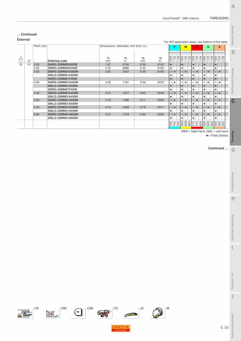
... ContinuedExternal
Pitch, mm Dimensions, millimeter, inch (mm, in.) P M K N S
D iC Ordering codeHA
mmHAin.
HBmm
HBin.
GC GC GC GC GC GC GC GC GC GC GC GC GC GC GC
1020
1125
1135
1020
1125
1135
1020
1125
1135
1020
1125
1135
1020
1125
1135
22 1/2 2.50 266RG-22MM02A250E 1.87 .0736 0.36 .0142 ★ ★ ★ ★ ★
3.00 266RG-22MM02A300E 2.25 .0886 0.42 .0165 ★ ★ ★ ★ ★
3.50 266RG-22MM01A350M 2.62 .1031 0.49 .0193 ✩ ★ ✩ ★ ✩ ★ ✩ ★ ✩ ★
266LG-22MM01A350M ★ ★ ★ ★ ★
266RG-22MM01F350E ★ ★ ★ ★ ★
4.00 266RG-22MM01A400M 3.00 .1181 0.56 .0220 ✩ ★ ✩ ★ ✩ ★ ✩ ★ ✩ ★
266LG-22MM01A400M ★ ★ ★ ★ ★
266RG-22MM01F400E ★ ★ ★ ★ ★
4.50 266RG-22MM01A450M 3.37 .1327 0.63 .0248 ✩ ★ ✩ ★ ✩ ★ ✩ ★ ✩ ★
266LG-22MM01A450M ★ ★ ★ ★ ★
5.00 266RG-22MM01A500M 3.76 .1480 0.71 .0280 ✩ ★ ✩ ★ ✩ ★ ✩ ★ ✩ ★
266LG-22MM01A500M ★ ★ ★ ★ ★
5.50 266RG-22MM01A550M 4.13 .1626 0.79 .0311 ✩ ★ ✩ ★ ✩ ★ ✩ ★ ✩ ★
266LG-22MM01A550M ★ ★ ★ ★ ★
6.00 266RG-22MM01A600M 4.51 .1776 0.86 .0339 ✩ ★ ✩ ★ ✩ ★ ✩ ★ ✩ ★
266LG-22MM01A600M ★ ★ ★ ★ ★
P20
P20
P25
M20
M20
M25
K15
K15
K20
N25
N20
N25
S20
S20
S25
266R = Right hand, 266L = Left hand
★= First choice
Continued ...
For ISO application areas, see bottom of the table.
C8 C82 C86 C2 J3 I8

C 16
THREADING CoroThread® 266 inserts
B
Gen
eral
Tur
ning
Par
ting
and
Gro
ovin
g
C
Thre
adin
g
G
Tool
ing
syst
ems
Mul
ti-ta
sk m
achi
ning
I
Cor
oTur
n® S
L
J
Gen
eral
info
rmat
ion
A
H
C
Thre
adin
g
THREADING CoroThread® 266 inserts
... ContinuedInternal
Pitch, mm Dimensions, millimeter, inch (mm, in.) P M K N S
D iC Ordering codeHA
mmHAin.
HBmm
HBin.
GC GC GC GC GC GC GC GC GC GC GC GC GC GC GC
1020
1125
1135
1020
1125
1135
1020
1125
1135
1020
1125
1135
1020
1125
1135
16 3/8 0.50 266RL-16MM01A050M 0.32 .0126 0.03 .0012 ★ ✩ ✩ ★ ★ ✩ ★ ✩ ✩ ★
266LL-16MM01A050M ★ ★ ★ ★ ★
0.75 266RL-16MM01A075M 0.47 .0185 0.04 .0016 ★ ✩ ✩ ★ ★ ✩ ★ ✩ ✩ ★
266LL-16MM01A075M ★ ★ ★ ★ ★
1.00 266RL-16MM03A100M 0.64 .0252 0.06 .0024 ★ ★ ★ ★ ★
266RL-16MM01A100M ★ ✩ ✩ ★ ★ ✩ ★ ✩ ✩ ★
266LL-16MM01A100M ★ ★ ★ ★ ★
266RL-16MM01C100M ★ ★ ★ ★ ★
266RL-16MM01F100E ★ ★ ★ ★ ★
1.25 266RL-16MM01A125M 0.79 .0311 0.07 .0028 ★ ✩ ✩ ★ ★ ✩ ★ ✩ ✩ ★
266LL-16MM01A125M ★ ★ ★ ★ ★
266RL-16MM01C125M ★ ★ ★ ★ ★
266RL-16MM01F125E ★ ★ ★ ★ ★
1.50 266RL-16MM02A150M 0.96 .0378 0.09 .0035 ★ ★ ★ ★ ★
266RL-16MM01A150M ★ ✩ ✩ ★ ★ ✩ ★ ✩ ✩ ★
266LL-16MM01A150M ★ ★ ★ ★ ★
266RL-16MM01C150M ★ ★ ★ ★ ★
266RL-16MM01F150E ★ ★ ★ ★ ★
1.75 266RL-16MM01A175M 1.11 .0437 0.11 .0043 ★ ✩ ✩ ★ ★ ✩ ★ ✩ ✩ ★
266LL-16MM01A175M ★ ★ ★ ★ ★
266RL-16MM01C175M ★ ★ ★ ★ ★
266RL-16MM01F175E ★ ★ ★ ★ ★
2.00 266RL-16MM02A200M 1.27 .0500 0.12 .0047 ★ ★ ★ ★ ★
266RL-16MM01A200M ★ ✩ ✩ ★ ★ ✩ ★ ✩ ✩ ★
266LL-16MM01A200M ★ ★ ★ ★ ★
266RL-16MM01C200M ★ ★ ★ ★ ★
266RL-16MM01F200E ★ ★ ★ ★ ★
2.50 266RL-16MM01A250M 1.59 .0626 0.16 .0063 ★ ✩ ✩ ★ ★ ✩ ★ ✩ ✩ ★
266LL-16MM01A250M ★ ★ ★ ★ ★
266RL-16MM01C250M ★ ★ ★ ★ ★
266RL-16MM01F250E ★ ★ ★ ★ ★
3.00 266RL-16MM01A300M 1.92 .0756 0.19 .0075 ★ ✩ ✩ ★ ★ ✩ ★ ✩ ✩ ★
266LL-16MM01A300M ★ ★ ★ ★ ★
266RL-16MM01C300M ★ ★ ★ ★ ★
266RL-16MM01F300E ★ ★ ★ ★ ★
22 1/2 2.50 266RL-22MM02A250E 1.59 .0626 0.16 .0063 ★ ★ ★ ★ ★
3.00 266RL-22MM02A300E 1.98 .0780 0.19 .0075 ★ ★ ★ ★ ★
3.50 266RL-22MM01A350M 2.24 .0882 0.26 .0102 ✩ ★ ✩ ★ ✩ ★ ✩ ★ ✩ ★
266LL-22MM01A350M ★ ★ ★ ★ ★
4.00 266RL-22MM01A400M 2.56 .1008 0.30 .0118 ✩ ★ ✩ ★ ✩ ★ ✩ ★ ✩ ★
266LL-22MM01A400M ★ ★ ★ ★ ★
4.50 266RL-22MM01A450M 2.89 .1138 0.33 .0130 ✩ ★ ✩ ★ ✩ ★ ✩ ★ ✩ ★
266LL-22MM01A450M ★ ★ ★ ★ ★
5.00 266RL-22MM01A500M 3.21 .1264 0.38 .0150 ✩ ★ ✩ ★ ✩ ★ ✩ ★ ✩ ★
266LL-22MM01A500M ★ ★ ★ ★ ★
5.50 266RL-22MM01A550M 3.54 .1394 0.40 .0157 ✩ ★ ✩ ★ ✩ ★ ✩ ★ ✩ ★
266LL-22MM01A550M ★ ★ ★ ★ ★
6.00 266RL-22MM01A600M 3.86 .1520 0.47 .0185 ✩ ★ ✩ ★ ✩ ★ ✩ ★ ✩ ★
266LL-22MM01A600M ★ ★ ★ ★ ★
P20
P20
P25
M20
M20
M25
K15
K15
K20
N25
N20
N25
S20
S20
S25
266R = Right hand, 266L = Left hand
★= First choice
For ISO application areas, see bottom of the table.
C8 C82 C86 C2 J3 I8

B
C 17
Gen
eral
Tur
ning
Par
ting
and
Gro
ovin
g
C
Thre
adin
g
G
Tool
ing
syst
ems
Mul
ti-ta
sk m
achi
ning
I
Cor
oTur
n® S
L
J
Gen
eral
info
rmat
ion
A
H
C
Thre
adin
g
CoroThread® 266 inserts THREADING
THREADING CoroThread® 266 inserts
UN 60° Full formThreads for general usage in all segments of engineering industry.
External
Single-point Multi-point
ISO 5864-1978
Tolerance class 2B, int.Style shown: Right hand external, Left hand internal
266RG-16UN0 3A180MTolerance class 2A, ext. |
2 = Two points3 = Three points
Pitch, TPI Dimensions, mm, inch P M K N S
D iC Ordering codeHA
mmHAin.
HBmm
HBin.
GC GC GC GC GC GC GC GC GC GC GC GC GC GC GC
1020
1125
1135
1020
1125
1135
1020
1125
1135
1020
1125
1135
1020
1125
1135
16 3/8 32 266RG-16UN01A320M 0.59 .0232 0.10 .0039 ★ ✩ ✩ ★ ★ ✩ ★ ✩ ✩ ★
266LG-16UN01A320M ★ ★ ★ ★ ★
28 266RG-16UN01A280M 0.67 .0264 0.12 .0047 ★ ✩ ✩ ★ ★ ✩ ★ ✩ ✩ ★
266LG-16UN01A280M ★ ★ ★ ★ ★
24 266RG-16UN01A240M 0.79 .0311 0.14 .0055 ★ ✩ ✩ ★ ★ ✩ ★ ✩ ✩ ★
266LG-16UN01A240M ★ ★ ★ ★ ★
266RG-16UN01C240M ★ ★ ★ ★ ★
266RG-16UN01F240E ★ ★ ★ ★ ★
20 266RG-16UN01A200M 0.95 .0374 0.16 .0063 ★ ✩ ✩ ★ ★ ✩ ★ ✩ ✩ ★
266LG-16UN01A200M ★ ★ ★ ★ ★
266RG-16UN01C200M ★ ★ ★ ★ ★
266RG-16UN01F200E ★ ★ ★ ★ ★
18 266RG-16UN03A180M 1.05 .0413 0.18 .0071 ★ ★ ★ ★ ★
266RG-16UN01A180M ★ ✩ ✩ ★ ★ ✩ ★ ✩ ✩ ★
266LG-16UN01A180M ★ ★ ★ ★ ★
266RG-16UN01C180M ★ ★ ★ ★ ★
266RG-16UN01F180E ★ ★ ★ ★ ★
16 266RG-16UN02A160M 1.19 .0469 0.20 .0079 ★ ★ ★ ★ ★
266RG-16UN01A160M ★ ✩ ✩ ★ ★ ✩ ★ ✩ ✩ ★
266LG-16UN01A160M ★ ★ ★ ★ ★
266RG-16UN01C160M ★ ★ ★ ★ ★
266RG-16UN01F160E ★ ★ ★ ★ ★
14 266RG-16UN02A140M 1.35 .0531 0.23 .0091 ★ ★ ★ ★ ★
266RG-16UN01A140M ★ ✩ ✩ ★ ★ ✩ ★ ✩ ✩ ★
266LG-16UN01A140M ★ ★ ★ ★ ★
266RG-16UN01C140M ★ ★ ★ ★ ★
266RG-16UN01F140E ★ ★ ★ ★ ★
13 266RG-16UN01A130M 1.46 .0575 0.25 .0098 ★ ✩ ✩ ★ ★ ✩ ★ ✩ ✩ ★
266LG-16UN01A130M ★ ★ ★ ★ ★
12 266RG-16UN02A120M 1.58 .0622 0.28 .0110 ★ ★ ★ ★ ★
266RG-16UN01A120M ★ ✩ ✩ ★ ★ ✩ ★ ✩ ✩ ★
266LG-16UN01A120M ★ ★ ★ ★ ★
266RG-16UN01C120M ★ ★ ★ ★ ★
266RG-16UN01F120E ★ ★ ★ ★ ★
11 266RG-16UN01A110M 1.72 .0677 0.30 .0118 ★ ✩ ✩ ★ ★ ✩ ★ ✩ ✩ ★
266LG-16UN01A110M ★ ★ ★ ★ ★
10 266RG-16UN01A100M 1.90 .0748 0.33 .0130 ★ ✩ ✩ ★ ★ ✩ ★ ✩ ✩ ★
266LG-16UN01A100M ★ ★ ★ ★ ★
9 266R/LG-16UN01A090M 2.11 .0831 0.37 .0146 ★ ★ ★ ★ ★
P20
P20
P25
M20
M20
M25
K15
K15
K20
N25
N20
N25
S20
S20
S25
266R = Right hand, 266L = Left hand
★= First choice
Continued ...
Dimensions, mm (inch)
D iCPitch, TPI iC mm d1 s
16 3/8 32-8 9.53 4.4 (.173) 3.97 (.156)22 1/2 7-4 12.7 5.5 (.217) 5.56 (.219) Even more possibilities thanks to tailored design! See page J3.
For ISO application areas, see bottom of the table.
C8 C82 C86 C2 J3 I8
C 18
THREADING CoroThread® 266 inserts
B
Gen
eral
Tur
ning
Par
ting
and
Gro
ovin
g
C
Thre
adin
g
G
Tool
ing
syst
ems
Mul
ti-ta
sk m
achi
ning
I
Cor
oTur
n® S
L
J
Gen
eral
info
rmat
ion
A
H
C
Thre
adin
g
THREADING CoroThread® 266 inserts
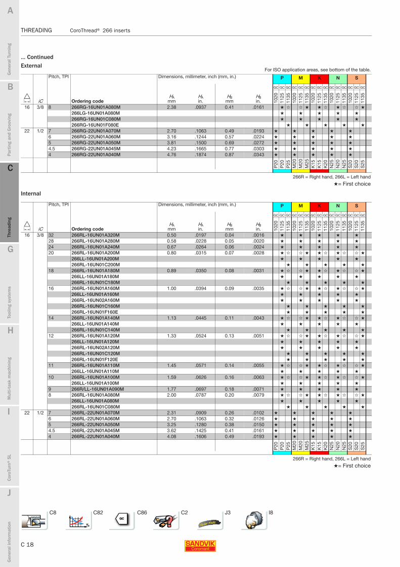
... ContinuedExternal
Internal
Pitch, TPI Dimensions, millimeter, inch (mm, in.) P M K N S
D iC Ordering codeHA
mmHAin.
HBmm
HBin.
GC GC GC GC GC GC GC GC GC GC GC GC GC GC GC
1020
1125
1135
1020
1125
1135
1020
1125
1135
1020
1125
1135
1020
1125
1135
16 3/8 8 266RG-16UN01A080M 2.38 .0937 0.41 .0161 ★ ✩ ✩ ★ ★ ✩ ★ ✩ ✩ ★
266LG-16UN01A080M ★ ★ ★ ★ ★
266RG-16UN01C080M ★ ★ ★ ★ ★
266RG-16UN01F080E ★ ★ ★ ★ ★
22 1/2 7 266RG-22UN01A070M 2.70 .1063 0.49 .0193 ★ ★ ★ ★ ★
6 266RG-22UN01A060M 3.16 .1244 0.57 .0224 ★ ★ ★ ★ ★
5 266RG-22UN01A050M 3.81 .1500 0.69 .0272 ★ ★ ★ ★ ★
4.5 266RG-22UN01A045M 4.23 .1665 0.77 .0303 ★ ★ ★ ★ ★
4 266RG-22UN01A040M 4.76 .1874 0.87 .0343 ★ ★ ★ ★ ★
P20
P20
P25
M20
M20
M25
K15
K15
K20
N25
N20
N25
S20
S20
S25
266R = Right hand, 266L = Left hand
★= First choice
Pitch, TPI Dimensions, millimeter, inch (mm, in.) P M K N S
D iC Ordering codeHA
mmHAin.
HBmm
HBin.
GC GC GC GC GC GC GC GC GC GC GC GC GC GC GC
1020
1125
1135
1020
1125
1135
1020
1125
1135
1020
1125
1135
1020
1125
1135
16 3/8 32 266RL-16UN01A320M 0.50 .0197 0.04 .0016 ★ ★ ★ ★ ★
28 266RL-16UN01A280M 0.58 .0228 0.05 .0020 ★ ★ ★ ★ ★
24 266RL-16UN01A240M 0.67 .0264 0.06 .0024 ★ ★ ★ ★ ★
20 266RL-16UN01A200M 0.80 .0315 0.07 .0028 ★ ✩ ✩ ★ ★ ✩ ★ ✩ ✩ ★
266LL-16UN01A200M ★ ★ ★ ★ ★
266RL-16UN01C200M ★ ★ ★ ★ ★
18 266RL-16UN01A180M 0.89 .0350 0.08 .0031 ★ ✩ ✩ ★ ★ ✩ ★ ✩ ✩ ★
266LL-16UN01A180M ★ ★ ★ ★ ★
266RL-16UN01C180M ★ ★ ★ ★ ★
16 266RL-16UN01A160M 1.00 .0394 0.09 .0035 ★ ✩ ✩ ★ ★ ✩ ★ ✩ ✩ ★
266LL-16UN01A160M ★ ★ ★ ★ ★
266RL-16UN02A160M ★ ★ ★ ★ ★
266RL-16UN01C160M ★ ★ ★ ★ ★
266RL-16UN01F160E ★ ★ ★ ★ ★
14 266RL-16UN01A140M 1.13 .0445 0.11 .0043 ★ ✩ ✩ ★ ★ ✩ ★ ✩ ✩ ★
266LL-16UN01A140M ★ ★ ★ ★ ★
266RL-16UN01C140M ★ ★ ★ ★ ★
12 266RL-16UN01A120M 1.33 .0524 0.13 .0051 ★ ✩ ✩ ★ ★ ✩ ★ ✩ ✩ ★
266LL-16UN01A120M ★ ★ ★ ★ ★
266RL-16UN02A120M ★ ★ ★ ★ ★
266RL-16UN01C120M ★ ★ ★ ★ ★
266RL-16UN01F120E ★ ★ ★ ★ ★
11 266RL-16UN01A110M 1.45 .0571 0.14 .0055 ★ ✩ ✩ ★ ★ ✩ ★ ✩ ✩ ★
266LL-16UN01A110M ★ ★ ★ ★ ★
10 266RL-16UN01A100M 1.59 .0626 0.16 .0063 ★ ✩ ✩ ★ ★ ✩ ★ ✩ ✩ ★
266LL-16UN01A100M ★ ★ ★ ★ ★
9 266R/LL-16UN01A090M 1.77 .0697 0.18 .0071 ★ ★ ★ ★ ★
8 266RL-16UN01A080M 2.00 .0787 0.20 .0079 ★ ✩ ✩ ★ ★ ✩ ★ ✩ ✩ ★
266LL-16UN01A080M ★ ★ ★ ★ ★
266RL-16UN01C080M ★ ★ ★ ★ ★
22 1/2 7 266RL-22UN01A070M 2.31 .0909 0.26 .0102 ★ ★ ★ ★ ★
6 266RL-22UN01A060M 2.70 .1063 0.32 .0126 ★ ★ ★ ★ ★
5 266RL-22UN01A050M 3.25 .1280 0.38 .0150 ★ ★ ★ ★ ★
4.5 266RL-22UN01A045M 3.62 .1425 0.41 .0161 ★ ★ ★ ★ ★
4 266RL-22UN01A040M 4.08 .1606 0.49 .0193 ★ ★ ★ ★ ★
P20
P20
P25
M20
M20
M25
K15
K15
K20
N25
N20
N25
S20
S20
S25
266R = Right hand, 266L = Left hand
★= First choice
For ISO application areas, see bottom of the table.
C8 C82 C86 C2 J3 I8

B
C 19
Gen
eral
Tur
ning
Par
ting
and
Gro
ovin
g
C
Thre
adin
g
G
Tool
ing
syst
ems
Mul
ti-ta
sk m
achi
ning
I
Cor
oTur
n® S
L
J
Gen
eral
info
rmat
ion
A
H
C
Thre
adin
g
CoroThread® 266 inserts THREADING
THREADING CoroThread® 266 inserts
Whitworth 55° (BSW, BSF, BSP) Full formThreads for pipe fittings and couplings for gas, water and sewage.
External
Single-point Multi-point
ISO 228-1982 Pipe threads 55°BS 2779-1973 External: G thread 266RG-22WH0 2A110EBS 84-1956 Internal: G/Rp threads |Class A tolerance Style shown: Right hand external, Left hand internal 2 = Two points
3 = Three points
Pitch, TPI Dimensions, millimeter, inch (mm, in.) P M K N S
D iC Ordering codeHA
mmHAin.
HBmm
HBin.
GC GC GC GC GC GC GC GC GC GC GC GC GC GC GC
1020
1125
1135
1020
1125
1135
1020
1125
1135
1020
1125
1135
1020
1125
1135
16 3/8 28 266RG-16WH01A280M 0.72 .0283 0.13 .0051 ★ ✩ ✩ ★ ★ ✩ ★ ✩ ✩ ★
26 266RG-16WH01A260M 0.77 .0303 0.14 .0055 ★ ★ ★ ★ ★
20 266RG-16WH01A200M 1.01 .0398 0.18 .0071 ★ ★ ★ ★ ★
19 266RG-16WH01A190M 1.06 .0417 0.19 .0075 ★ ✩ ✩ ★ ★ ✩ ★ ✩ ✩ ★
266LG-16WH01A190M ★ ★ ★ ★ ★
266RG-16WH03A190M ★ ★ ★ ★ ★
266RG-16WH01C190M ★ ★ ★ ★ ★
266RG-16WH01F190E ★ ★ ★ ★ ★
18 266RG-16WH01A180M 1.12 .0441 0.20 .0079 ★ ★ ★ ★ ★
16 266RG-16WH01A160M 1.26 .0496 0.23 .0091 ★ ★ ★ ★ ★
14 266RG-16WH01A140M 1.44 .0567 0.26 .0102 ★ ✩ ✩ ★ ★ ✩ ★ ✩ ✩ ★
266LG-16WH01A140M ★ ★ ★ ★ ★
266RG-16WH02A140M ★ ★ ★ ★ ★
266RG-16WH01C140M ★ ★ ★ ★ ★
266RG-16WH01F140E ★ ★ ★ ★ ★
12 266RG-16WH01A120M 1.68 .0661 0.31 .0122 ★ ★ ★ ★ ★
11 266RG-16WH01A110M 1.83 .0720 0.34 .0134 ★ ✩ ✩ ★ ★ ✩ ★ ✩ ✩ ★
266LG-16WH01A110M ★ ★ ★ ★ ★
266RG-16WH01C110M ★ ★ ★ ★ ★
266RG-16WH01F110E ★ ★ ★ ★ ★
10 266RG-16WH01A100M 2.02 .0795 0.37 .0146 ★ ★ ★ ★ ★
9 266RG-16WH01A090M 2.24 .0882 0.42 .0165 ★ ★ ★ ★ ★
8 266RG-16WH01A080M 2.52 .0992 0.47 .0185 ★ ✩ ✩ ★ ★ ✩ ★ ✩ ✩ ★
22 1/2 11 266RG-22WH02A110E 1.83 .0720 0.34 .0134 ★ ★ ★ ★ ★
7 266RG-22WH01A070M 2.88 .1134 0.54 .0213 ★ ★ ★ ★ ★
6 266RG-22WH01A060M 3.37 .1327 0.64 .0252 ★ ★ ★ ★ ★
5 266RG-22WH01A050M 4.04 .1591 0.77 .0303 ★ ★ ★ ★ ★
4.5 266RG-22WH01A045M 4.49 .1768 0.85 .0335 ★ ★ ★ ★ ★
4 266RG-22WH01A040M 5.06 .1992 0.96 .0378 ★ ★ ★ ★ ★
P20
P20
P25
M20
M20
M25
K15
K15
K20
N25
N20
N25
S20
S20
S25
266R = Right hand, 266L = Left hand★= First choice
Continued ...
Dimensions, mm (inch)
D iCPitch, TPI iC mm d1 s
16 3/8 28-8 9.53 4.4 (.173) 3.97 (.156)22 1/2 11-4 12.7 5.5 (.217) 5.56 (.219) Even more possibilities thanks to tailored design! See page J3.
For ISO application areas, see bottom of the table.
C8 C82 C86 C2 J3 I8
C 20
THREADING CoroThread® 266 inserts
B
Gen
eral
Tur
ning
Par
ting
and
Gro
ovin
g
C
Thre
adin
g
G
Tool
ing
syst
ems
Mul
ti-ta
sk m
achi
ning
I
Cor
oTur
n® S
L
J
Gen
eral
info
rmat
ion
A
H
C
Thre
adin
g
THREADING CoroThread® 266 inserts
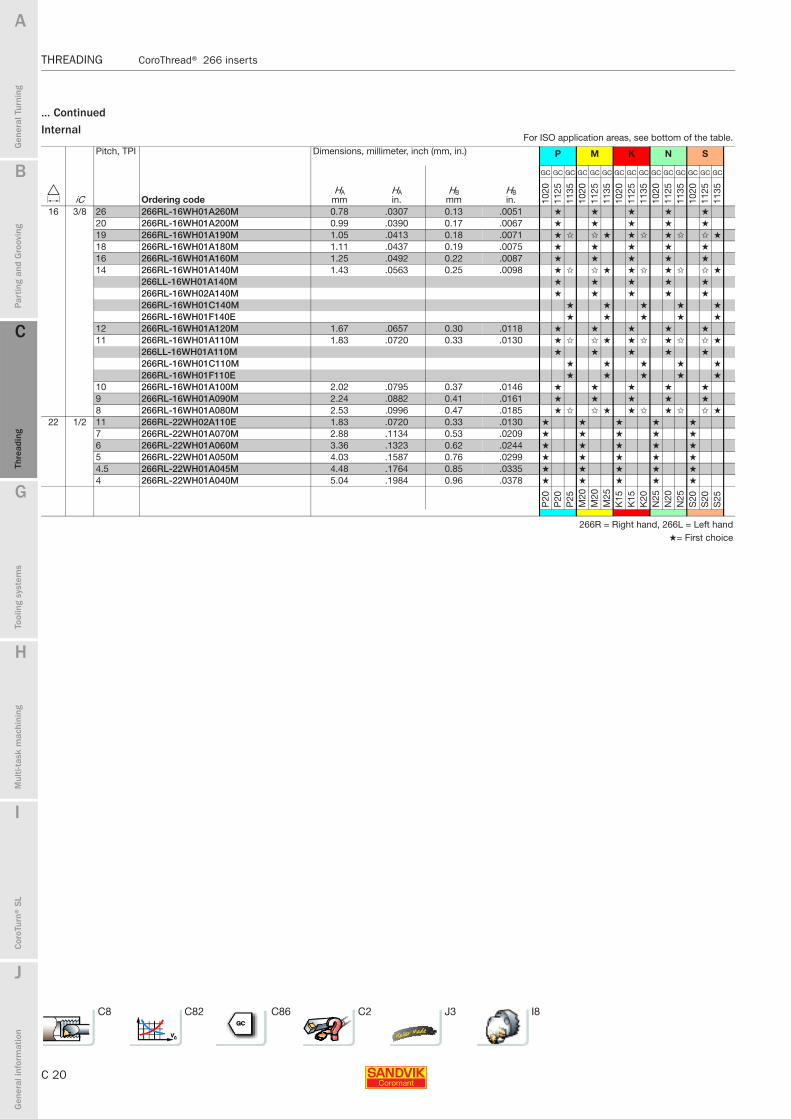
... ContinuedInternal
Pitch, TPI Dimensions, millimeter, inch (mm, in.) P M K N S
D iC Ordering codeHA
mmHAin.
HBmm
HBin.
GC GC GC GC GC GC GC GC GC GC GC GC GC GC GC
1020
1125
1135
1020
1125
1135
1020
1125
1135
1020
1125
1135
1020
1125
1135
16 3/8 26 266RL-16WH01A260M 0.78 .0307 0.13 .0051 ★ ★ ★ ★ ★
20 266RL-16WH01A200M 0.99 .0390 0.17 .0067 ★ ★ ★ ★ ★
19 266RL-16WH01A190M 1.05 .0413 0.18 .0071 ★ ✩ ✩ ★ ★ ✩ ★ ✩ ✩ ★
18 266RL-16WH01A180M 1.11 .0437 0.19 .0075 ★ ★ ★ ★ ★
16 266RL-16WH01A160M 1.25 .0492 0.22 .0087 ★ ★ ★ ★ ★
14 266RL-16WH01A140M 1.43 .0563 0.25 .0098 ★ ✩ ✩ ★ ★ ✩ ★ ✩ ✩ ★
266LL-16WH01A140M ★ ★ ★ ★ ★
266RL-16WH02A140M ★ ★ ★ ★ ★
266RL-16WH01C140M ★ ★ ★ ★ ★
266RL-16WH01F140E ★ ★ ★ ★ ★
12 266RL-16WH01A120M 1.67 .0657 0.30 .0118 ★ ★ ★ ★ ★
11 266RL-16WH01A110M 1.83 .0720 0.33 .0130 ★ ✩ ✩ ★ ★ ✩ ★ ✩ ✩ ★
266LL-16WH01A110M ★ ★ ★ ★ ★
266RL-16WH01C110M ★ ★ ★ ★ ★
266RL-16WH01F110E ★ ★ ★ ★ ★
10 266RL-16WH01A100M 2.02 .0795 0.37 .0146 ★ ★ ★ ★ ★
9 266RL-16WH01A090M 2.24 .0882 0.41 .0161 ★ ★ ★ ★ ★
8 266RL-16WH01A080M 2.53 .0996 0.47 .0185 ★ ✩ ✩ ★ ★ ✩ ★ ✩ ✩ ★
22 1/2 11 266RL-22WH02A110E 1.83 .0720 0.33 .0130 ★ ★ ★ ★ ★
7 266RL-22WH01A070M 2.88 .1134 0.53 .0209 ★ ★ ★ ★ ★
6 266RL-22WH01A060M 3.36 .1323 0.62 .0244 ★ ★ ★ ★ ★
5 266RL-22WH01A050M 4.03 .1587 0.76 .0299 ★ ★ ★ ★ ★
4.5 266RL-22WH01A045M 4.48 .1764 0.85 .0335 ★ ★ ★ ★ ★
4 266RL-22WH01A040M 5.04 .1984 0.96 .0378 ★ ★ ★ ★ ★
P20
P20
P25
M20
M20
M25
K15
K15
K20
N25
N20
N25
S20
S20
S25
266R = Right hand, 266L = Left hand★= First choice
For ISO application areas, see bottom of the table.
C8 C82 C86 C2 J3 I8

B
C 21
Gen
eral
Tur
ning
Par
ting
and
Gro
ovin
g
C
Thre
adin
g
G
Tool
ing
syst
ems
Mul
ti-ta
sk m
achi
ning
I
Cor
oTur
n® S
L
J
Gen
eral
info
rmat
ion
A
H
C
Thre
adin
g
CoroThread® 266 inserts THREADING
THREADING CoroThread® 266 inserts
NPT 60° NPSC, NPTR, LINE PIPE1) Full formThreads for pipe fittings and couplings for gas, water and sewage.
External
Internal
Single-point Multi-point
ANSI B.1.20.1-1983 Style shown: Right hand external, Left hand internal
266RG-22NT0 2A115E|2 = Two points
Pitch, TPI Dimensions, millimeter, inch (mm, in.) P M K N S
D iC Ordering codeHA
mmHAin.
HBmm
HBin.
GC GC GC GC GC GC GC GC GC GC GC GC GC GC GC
1020
1125
1135
1020
1125
1135
1020
1125
1135
1020
1125
1135
1020
1125
1135
16 3/8 27 266RG-16NT01A270M 0.76 .0299 0.05 .0020 ★ ✩ ✩ ★ ★ ✩ ★ ✩ ✩ ★
266LG-16NT01A270M ★ ★ ★ ★ ★
18 266RG-16NT01A180M 1.14 .0449 0.08 .0031 ★ ✩ ✩ ★ ★ ✩ ★ ✩ ✩ ★
266LG-16NT01A180M ★ ★ ★ ★ ★
14 266RG-16NT01A140M 1.46 .0575 0.09 .0035 ★ ✩ ★ ★ ✩ ★ ✩ ★
266LG-16NT01A140M ★ ★ ★ ★ ★
266RG-16NT01C140M ★ ★ ★ ★ ★
266RG-16NT01F140E ★ ★ ★ ★ ★
11.5 266RG-16NT01A115M 1.79 .0705 0.11 .0043 ★ ✩ ✩ ★ ★ ✩ ★ ✩ ✩ ★
266LG-16NT01A115M ★ ★ ★ ★ ★
266RG-16NT01C115M ★ ★ ★ ★ ★
266RG-16NT01F115E ★ ★ ★ ★ ★
8 266RG-16NT01A080M 2.57 .1012 0.14 .0055 ★ ✩ ✩ ★ ★ ✩ ★ ✩ ✩ ★
266LG-16NT01A080M ★ ★ ★ ★ ★
22 1/2 11.5 266RG-22NT02A115E 1.79 .0705 0.11 .0043 ★ ★ ★ ★ ★
P20
P20
P25
M20
M20
M25
K15
K15
K20
N25
N20
N25
S20
S20
S25
Pitch, TPI Dimensions, millimeter, inch (mm, in.) P M K N S
D iC Ordering codeHA
mmHAin.
HBmm
HBin.
GC GC GC GC GC GC GC GC GC GC GC GC GC GC GC
1020
1125
1135
1020
1125
1135
1020
1125
1135
1020
1125
1135
1020
1125
1135
16 3/8 14 266RL-16NT01A140M 1.46 .0575 0.09 .0035 ★ ✩ ✩ ★ ★ ✩ ★ ✩ ✩ ★
266LL-16NT01A140M ★ ★ ★ ★ ★
266RL-16NT01C140M ★ ★ ★ ★ ★
266RL-16NT01F140E ★ ★ ★ ★ ★
11.5 266RL-16NT01A115M 1.79 .0705 0.11 .0043 ★ ✩ ✩ ★ ★ ✩ ★ ✩ ✩ ★
266LL-16NT01A115M ★ ★ ★ ★ ★
266RL-16NT01C115M ★ ★ ★ ★ ★
266RL-16NT01F115E ★ ★ ★ ★ ★
8 266RL-16NT01A080M 2.57 .1012 0.14 .0055 ★ ✩ ✩ ★ ★ ✩ ★ ✩ ✩ ★
266LL-16NT01A080M ★ ★ ★ ★ ★
22 1/2 11.5 266RL-22NT02A115E 1.79 .0705 0.11 .0043 ★ ★ ★ ★ ★
P20
P20
P25
M20
M20
M25
K15
K15
K20
N25
N20
N25
S20
S20
S25
1) The insert can give a slightly bigger truncation for LINE PIPE 14 TPI. 266R = Right hand, 266L = Left hand★= First choice
Dimensions, mm (inch)
D iCPitch, TPI iC mm d1 s
16 3/8 27-8 9.53 4.4 (.173) 3.97 (.156)22 1/2 11-4 12.7 5.5 (.217) 5.56 (.219) Even more possibilities thanks to tailored design! See page J3.
For ISO application areas, see bottom of the table.
C8 C82 C86 C2 J3 I8

C 22
THREADING CoroThread® 266 inserts
B
Gen
eral
Tur
ning
Par
ting
and
Gro
ovin
g
C
Thre
adin
g
G
Tool
ing
syst
ems
Mul
ti-ta
sk m
achi
ning
I
Cor
oTur
n® S
L
J
Gen
eral
info
rmat
ion
A
H
C
Thre
adin
g
THREADING CoroThread® 266 inserts
BSPT 55° Full formPipe threads for steam, gas and water lines
External
Internal
ISO 7/1 Pipe threadsBS21:1985 External: R thread
Internal: Rc threadStyle shown: Right hand external, Left hand internal
Pitch, TPI Dimensions, mm, inch P M K N S
D iC Ordering codeHA
mmHAin.
HBmm
HBin.
GC GC GC GC GC GC GC GC GC GC
1125
1135
1125
1135
1125
1135
1125
1135
1125
1135
16 3/8 28 266RG-16PT01A280E 0.70 .0276 0.13 .0051 ★ ✩ ✩ ★ ★ ✩ ★ ✩ ✩ ★
19 266RG-16PT01A190E 1.04 .0409 0.19 .0075 ★ ✩ ✩ ★ ★ ✩ ★ ✩ ✩ ★
266LG-16PT01A190E ★ ★ ★ ★ ★
14 266RG-16PT01A140E 1.41 .0555 0.26 .0102 ★ ✩ ✩ ★ ★ ✩ ★ ✩ ✩ ★
266LG-16PT01A140E ★ ★ ★ ★ ★
11 266RG-16PT01A110E 1.80 .0709 0.34 .0134 ★ ✩ ✩ ★ ★ ✩ ★ ✩ ✩ ★
266LG-16PT01A110E ★ ★ ★ ★ ★
8 266RG-16PT01A080E 2.47 .0972 0.47 .0185 ★ ★ ★ ★ ★
P20
P25
M20
M25
K15
K20
N20
N25
S20
S25
Pitch, TPI Dimensions, mm, inch P M K N S
D iC Ordering codeHA
mmHAin.
HBmm
HBin.
GC GC GC GC GC GC GC GC GC GC
1125
1135
1125
1135
1125
1135
1125
1135
1125
1135
16 28 28 266RL-16PT01A280E 0.71 .0280 0.12 .0047 ★ ★ ★ ★ ★
19 266R/LL-16PT01A190E 1.03 .0406 0.18 .0071 ★ ★ ★ ★ ★
14 266RL-16PT01A140E 1.40 .0551 0.25 .0098 ★ ✩ ✩ ★ ★ ✩ ★ ✩ ✩ ★
266LL-16PT01A140E ★ ★ ★ ★ ★
11 266RL-16PT01A110E 1.80 .0709 0.33 .0130 ★ ✩ ✩ ★ ★ ✩ ★ ✩ ✩ ★
266LL-16PT01A110E ★ ★ ★ ★ ★
8 266RL-16PT01A080E 2.48 .0976 0.47 .0185 ★ ★ ★ ★ ★
P20
P25
M20
M25
K15
K20
N20
N25
S20
S25
266R = Right hand, 266L = Left hand★= First choice
Dimensions, mm (inch)
D iCPitch, TPI iC mm d1 s
16 3/8 28-8 9.53 4.4 (.173) 3.97 (.156)Even more possibilities thanks to tailored design! See page J3.
For ISO application areas, see bottom of the table.
C8 C82 C86 C2 J3 I8

B
C 23
Gen
eral
Tur
ning
Par
ting
and
Gro
ovin
g
C
Thre
adin
g
G
Tool
ing
syst
ems
Mul
ti-ta
sk m
achi
ning
I
Cor
oTur
n® S
L
J
Gen
eral
info
rmat
ion
A
H
C
Thre
adin
g
CoroThread® 266 inserts THREADING
THREADING CoroThread® 266 inserts
NPTF 60° Full formPipe threads for steam, gas and water lines.
External
Internal
ANSI B1.20.3-1976 Style shown: Right hand external
Tolerance class 2 Left hand internal
Pitch, TPI Dimensions, mm, inch P M K N S
D iC Ordering codeHA
mmHAin.
HBmm
HBin.
GC GC GC GC GC
1125
1125
1125
1125
1125
16 3/8 27 266RG-16NF01A270E 0.75 .0295 0.11 .0043 ★ ★ ★ ★ ★
18 266RG-16NF01A180E 1.14 .0449 0.13 .0051 ★ ★ ★ ★ ★
14 266RG-16NF01A140E 1.49 .0587 0.13 .0051 ★ ★ ★ ★ ★
11.5 266RG-16NF01A115E 1.81 .0713 0.17 .0067 ★ ★ ★ ★ ★
8 266RG-16NF01A080E 2.60 .1024 0.21 .0083 ★ ★ ★ ★ ★
P20
M20
K15
N20
S20
Pitch, TPI Dimensions, mm, inch P M K N S
D iC Ordering codeHA
mmHAin.
HBmm
HBin.
GC GC GC GC GC
1125
1125
1125
1125
1125
16 3/8 14 266RL-16NF01A140E 1.49 .0587 0.13 .0051 ★ ★ ★ ★ ★
11.5 266RL-16NF01A115E 1.81 .0713 0.17 .0067 ★ ★ ★ ★ ★
8 266RL-16NF01A080E 2.60 .1024 0.21 .0083 ★ ★ ★ ★ ★
P20
M20
K15
N20
S20
266R = Right hand, 266L = Left hand★= First choice
Dimensions, mm (inch)
D iCPitch, TPI iC mm d1 s
16 3/8 27-8 9.53 4.4 (.173) 3.97 (.156)Even more possibilities thanks to tailored design! See page J3.
For ISO application areas, see bottom of the table.
C8 C82 C86 C2 J3 I8
C 24
THREADING CoroThread® 266 inserts
B
Gen
eral
Tur
ning
Par
ting
and
Gro
ovin
g
C
Thre
adin
g
G
Tool
ing
syst
ems
Mul
ti-ta
sk m
achi
ning
I
Cor
oTur
n® S
L
J
Gen
eral
info
rmat
ion
A
H
C
Thre
adin
g
THREADING CoroThread® 266 inserts
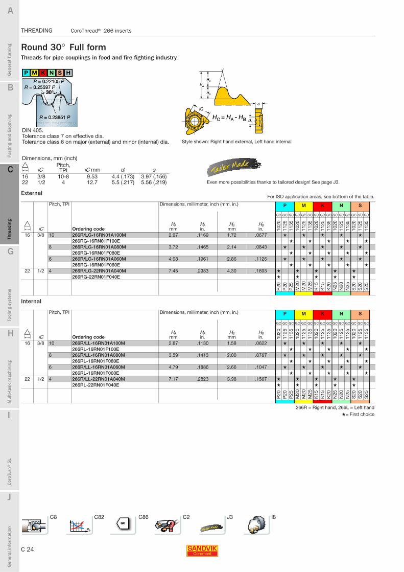
Round 30° Full formThreads for pipe couplings in food and fire fighting industry.
External
Internal
DIN 405.Tolerance class 7 on effective dia.Tolerance class 6 on major (external) and minor (internal) dia. Style shown: Right hand external, Left hand internal
Pitch, TPI Dimensions, millimeter, inch (mm, in.) P M K N S
D iC Ordering codeHA
mmHAin.
HBmm
HBin.
GC GC GC GC GC GC GC GC GC GC GC GC GC GC GC
1020
1125
1135
1020
1125
1135
1020
1125
1135
1020
1125
1135
1020
1125
1135
16 3/8 10 266R/LG-16RN01A100M 2.97 .1169 1.72 .0677 ★ ★ ★ ★ ★
266RG-16RN01F100E ★ ★ ★ ★ ★
8 266R/LG-16RN01A080M 3.72 .1465 2.14 .0843 ★ ★ ★ ★ ★
266RG-16RN01F080E ★ ★ ★ ★ ★
6 266R/LG-16RN01A060M 4.98 .1961 2.86 .1126 ★ ★ ★ ★ ★
266RG-16RN01F060E ★ ★ ★ ★ ★
22 1/2 4 266R/LG-22RN01A040M 7.45 .2933 4.30 .1693 ★ ★ ★ ★ ★
266RG-22RN01F040E ★ ★ ★ ★ ★P
20P
20P
25M
20M
20M
25K
15K
15K
20N
25N
20N
25S
20S
20S
25
Pitch, TPI Dimensions, millimeter, inch (mm, in.) P M K N S
D iC Ordering codeHA
mmHAin.
HBmm
HBin.
GC GC GC GC GC GC GC GC GC GC GC GC GC GC GC
1020
1125
1135
1020
1125
1135
1020
1125
1135
1020
1125
1135
1020
1125
1135
16 3/8 10 266R/LL-16RN01A100M 2.87 .1130 1.58 .0622 ★ ★ ★ ★ ★
266RL-16RN01F100E ★ ★ ★ ★ ★
8 266R/LL-16RN01A080M 3.59 .1413 2.00 .0787 ★ ★ ★ ★ ★
266RL-16RN01F080E ★ ★ ★ ★ ★
6 266R/LL-16RN01A060M 4.79 .1886 2.66 .1047 ★ ★ ★ ★ ★
266RL-16RN01F060E ★ ★ ★ ★ ★
22 1/2 4 266R/LL-22RN01A040M 7.17 .2823 3.98 .1567 ★ ★ ★ ★ ★
266RL-22RN01F040E ★ ★ ★ ★ ★
P20
P20
P25
M20
M20
M25
K15
K15
K20
N25
N20
N25
S20
S20
S25
266R = Right hand, 266L = Left hand★= First choice
Dimensions, mm (inch)
D iCPitch, TPI iC mm d1 s
16 3/8 10-8 9.53 4.4 (.173) 3.97 (.156)22 1/2 4 12.7 5.5 (.217) 5.56 (.219) Even more possibilities thanks to tailored design! See page J3.
For ISO application areas, see bottom of the table.
C8 C82 C86 C2 J3 I8
B
C 25
Gen
eral
Tur
ning
Par
ting
and
Gro
ovin
g
C
Thre
adin
g
G
Tool
ing
syst
ems
Mul
ti-ta
sk m
achi
ning
I
Cor
oTur
n® S
L
J
Gen
eral
info
rmat
ion
A
H
C
Thre
adin
g
CoroThread® 266 inserts THREADING
THREADING CoroThread® 266 inserts
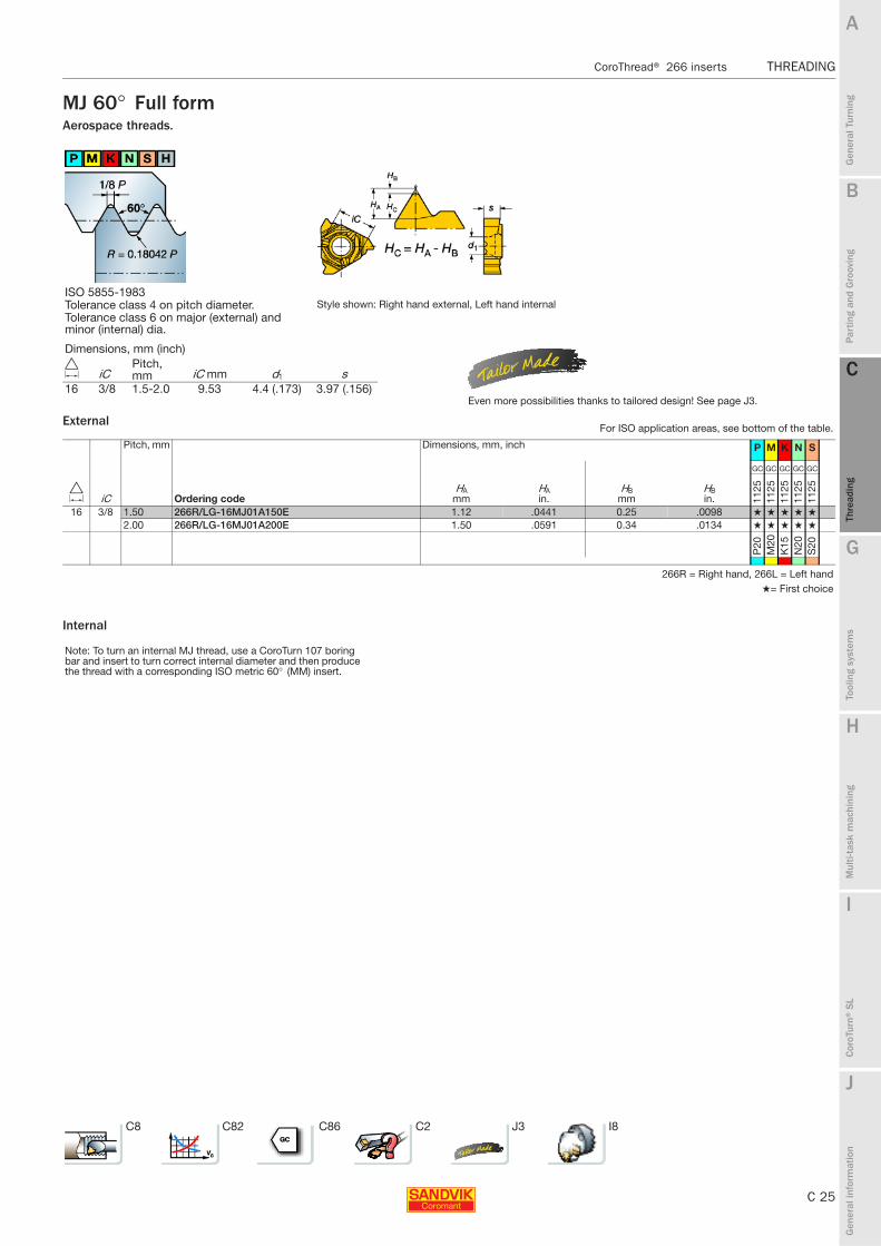
MJ 60° Full formAerospace threads.
External
Internal
ISO 5855-1983Tolerance class 4 on pitch diameter. Style shown: Right hand external, Left hand internalTolerance class 6 on major (external) and minor (internal) dia.
Pitch, mm Dimensions, mm, inch P M K N S
D iC Ordering codeHA
mmHAin.
HBmm
HBin.
GC GC GC GC GC
1125
1125
1125
1125
1125
16 3/8 1.50 266R/LG-16MJ01A150E 1.12 .0441 0.25 .0098 ★ ★ ★ ★ ★
2.00 266R/LG-16MJ01A200E 1.50 .0591 0.34 .0134 ★ ★ ★ ★ ★
P20
M20
K15
N20
S20
266R = Right hand, 266L = Left hand★= First choice
Note: To turn an internal MJ thread, use a CoroTurn 107 boring bar and insert to turn correct internal diameter and then produce the thread with a corresponding ISO metric 60° (MM) insert.
Dimensions, mm (inch)
D iCPitch, mm iC mm d1 s
16 3/8 1.5-2.0 9.53 4.4 (.173) 3.97 (.156)Even more possibilities thanks to tailored design! See page J3.
For ISO application areas, see bottom of the table.
C8 C82 C86 C2 J3 I8

C 26
THREADING CoroThread® 266 inserts
B
Gen
eral
Tur
ning
Par
ting
and
Gro
ovin
g
C
Thre
adin
g
G
Tool
ing
syst
ems
Mul
ti-ta
sk m
achi
ning
I
Cor
oTur
n® S
L
J
Gen
eral
info
rmat
ion
A
H
C
Thre
adin
g
THREADING CoroThread® 266 inserts
UNJ 60° Full formAerospace threads.
External
Internal
ISO 3161-1977BS 4084-1978 Style shown: Right hand external, Left hand internalTolerance class 3A
Pitch, TPI Dimensions, millimeter, inch (mm, in.) P M K N S
D iC Ordering codeHA
mmHAin.
HBmm
HBin.
GC GC GC GC GC
1125
1125
1125
1125
1125
16 3/8 32 266RG-16NJ01A320E 0.59 .0232 0.13 .0051 ★ ★ ★ ★ ★
28 266RG-16NJ01A280E 0.67 .0264 0.15 .0059 ★ ★ ★ ★ ★
24 266RG-16NJ01A240E 0.79 .0311 0.18 .0071 ★ ★ ★ ★ ★
20 266RG-16NJ01A200E 0.94 .0370 0.21 .0083 ★ ★ ★ ★ ★
18 266RG-16NJ01A180E 1.05 .0413 0.23 .0091 ★ ★ ★ ★ ★
16 266RG-16NJ01A160E 1.18 .0465 0.26 .0102 ★ ★ ★ ★ ★
14 266RG-16NJ01A140E 1.35 .0531 0.30 .0118 ★ ★ ★ ★ ★
12 266RG-16NJ01A120E 1.58 .0622 0.36 .0142 ★ ★ ★ ★ ★
10 266RG-16NJ01A100E 1.89 .0744 0.42 .0165 ★ ★ ★ ★ ★
8 266RG-16NJ01A080E 2.38 .0937 0.53 .0209 ★ ★ ★ ★ ★
P20
M20
K15
N20
S20
266R = Right hand, 266L = Left hand★= First choice
Note: To turn an internal UNJ thread use a CoroTurn 107 boring bar and insert to turn correct internal diameter and then produce the thread with a corresponding UN 60° insert.
Dimensions, mm (inch)
D iCPitch, TPI iC mm d1 s
16 3/8 32-8 9.53 4.4 (.173) 3.97 (.156)Even more possibilities thanks to tailored design! See page J3.
For ISO application areas, see bottom of the table.
C8 C82 C86 C2 J3 I8
B
C 27
Gen
eral
Tur
ning
Par
ting
and
Gro
ovin
g
C
Thre
adin
g
G
Tool
ing
syst
ems
Mul
ti-ta
sk m
achi
ning
I
Cor
oTur
n® S
L
J
Gen
eral
info
rmat
ion
A
H
C
Thre
adin
g
CoroThread® 266 inserts THREADING
THREADING CoroThread® 266 inserts
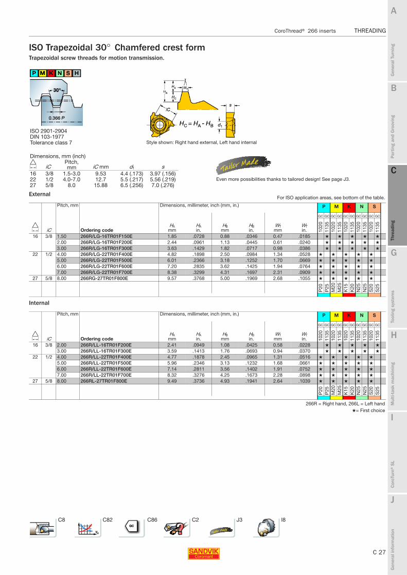
ISO Trapezoidal 30° Chamfered crest formTrapezoidal screw threads for motion transmission.
External
Internal
ISO 2901-2904DIN 103-1977Tolerance class 7 Style shown: Right hand external, Left hand internal
Pitch, mm Dimensions, millimeter, inch (mm, in.) P M K N S
D iC Ordering codeHA
mmHAin.
HBmm
HBin.
WTmm
WTin.
GC GC GC GC GC GC GC GC GC GC
1020
1135
1020
1135
1020
1135
1020
1135
1020
1135
16 3/8 1.50 266R/LG-16TR01F150E 1.85 .0728 0.88 .0346 0.47 .0185 ★ ★ ★ ★ ★
2.00 266R/LG-16TR01F200E 2.44 .0961 1.13 .0445 0.61 .0240 ★ ★ ★ ★ ★
3.00 266R/LG-16TR01F300E 3.63 .1429 1.82 .0717 0.98 .0386 ★ ★ ★ ★ ★
22 1/2 4.00 266R/LG-22TR01F400E 4.82 .1898 2.50 .0984 1.34 .0528 ★ ★ ★ ★ ★
5.00 266R/LG-22TR01F500E 6.01 .2366 3.18 .1252 1.70 .0669 ★ ★ ★ ★ ★
6.00 266R/LG-22TR01F600E 7.20 .2835 3.62 .1425 1.94 .0764 ★ ★ ★ ★ ★
7.00 266R/LG-22TR01F700E 8.38 .3299 4.31 .1697 2.31 .0909 ★ ★ ★ ★ ★
27 5/8 8.00 266RG-27TR01F800E 9.57 .3768 5.00 .1969 2.68 .1055 ★ ★ ★ ★ ★
P20
P25
M20
M25
K15
K20
N25
N25
S20
S25
Pitch, mm Dimensions, millimeter, inch (mm, in.) P M K N S
D iC Ordering codeHA
mmHAin.
HBmm
HBin.
WTmm
WTin.
GC GC GC GC GC GC GC GC GC GC10
2011
3510
2011
3510
2011
3510
2011
3510
2011
35
16 3/8 2.00 266R/LL-16TR01F200E 2.41 .0949 1.08 .0425 0.58 .0228 ★ ★ ★ ★ ★
3.00 266R/LL-16TR01F300E 3.59 .1413 1.76 .0693 0.94 .0370 ★ ★ ★ ★ ★
22 1/2 4.00 266R/LL-22TR01F400E 4.77 .1878 2.45 .0965 1.31 .0516 ★ ★ ★ ★ ★
5.00 266R/LL-22TR01F500E 5.96 .2346 3.13 .1232 1.68 .0661 ★ ★ ★ ★ ★
6.00 266R/LL-22TR01F600E 7.14 .2811 3.56 .1402 1.91 .0752 ★ ★ ★ ★ ★
7.00 266R/LL-22TR01F700E 8.32 .3276 4.25 .1673 2.28 .0898 ★ ★ ★ ★ ★
27 5/8 8.00 266RL-27TR01F800E 9.49 .3736 4.93 .1941 2.64 .1039 ★ ★ ★ ★ ★
P20
P25
M20
M25
K15
K20
N25
N25
S20
S25
266R = Right hand, 266L = Left hand★= First choice
Dimensions, mm (inch)
D iCPitch, mm iC mm d1 s
16 3/8 1.5-3.0 9.53 4.4 (.173) 3.97 (.156)22 1/2 4.0-7.0 12.7 5.5 (.217) 5.56 (.219) Even more possibilities thanks to tailored design! See page J3.27 5/8 8.0 15.88 6.5 (.256) 7.0 (.276)
For ISO application areas, see bottom of the table.
C8 C82 C86 C2 J3 I8
C 28
THREADING CoroThread® 266 inserts
B
Gen
eral
Tur
ning
Par
ting
and
Gro
ovin
g
C
Thre
adin
g
G
Tool
ing
syst
ems
Mul
ti-ta
sk m
achi
ning
I
Cor
oTur
n® S
L
J
Gen
eral
info
rmat
ion
A
H
C
Thre
adin
g
THREADING CoroThread® 266 inserts
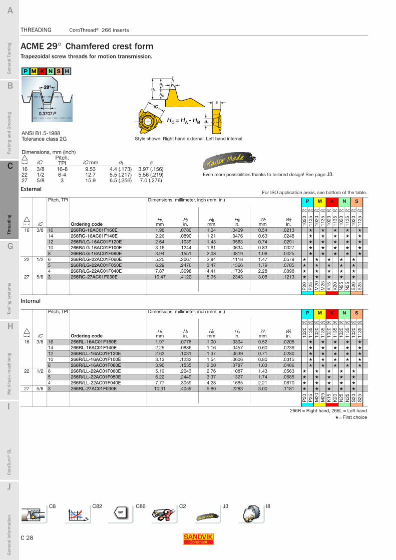
ACME 29° Chamfered crest formTrapezoidal screw threads for motion transmission.
External
Internal
ANSI B1.5-1988Tolerance class 2G Style shown: Right hand external, Left hand internal
Pitch, TPI Dimensions, millimeter, inch (mm, in.) P M K N S
D iC Ordering codeHA
mmHAin.
HBmm
HBin.
WTmm
WTin.
GC GC GC GC GC GC GC GC GC GC
1020
1135
1020
1135
1020
1135
1020
1135
1020
1135
16 3/8 16 266RG-16AC01F160E 1.98 .0780 1.04 .0409 0.54 .0213 ★ ★ ★ ★ ★
14 266RG-16AC01F140E 2.26 .0890 1.21 .0476 0.63 .0248 ★ ★ ★ ★ ★
12 266R/LG-16AC01F120E 2.64 .1039 1.43 .0563 0.74 .0291 ★ ★ ★ ★ ★
10 266R/LG-16AC01F100E 3.16 .1244 1.61 .0634 0.83 .0327 ★ ★ ★ ★ ★
8 266R/LG-16AC01F080E 3.94 .1551 2.08 .0819 1.08 .0425 ★ ★ ★ ★ ★
22 1/2 6 266R/LG-22AC01F060E 5.25 .2067 2.84 .1118 1.47 .0579 ★ ★ ★ ★ ★
5 266R/LG-22AC01F050E 6.29 .2476 3.47 .1366 1.79 .0705 ★ ★ ★ ★ ★
4 266R/LG-22AC01F040E 7.87 .3098 4.41 .1736 2.28 .0898 ★ ★ ★ ★ ★
27 5/8 3 266RG-27AC01F030E 10.47 .4122 5.95 .2343 3.08 .1213 ★ ★ ★ ★ ★
P20
P25
M20
M25
K15
K20
N25
N25
S20
S25
Pitch, TPI Dimensions, millimeter, inch (mm, in.) P M K N S
D iC Ordering codeHA
mmHAin.
HBmm
HBin.
WTmm
WTin.
GC GC GC GC GC GC GC GC GC GC
1020
1135
1020
1135
1020
1135
1020
1135
1020
1135
16 3/8 16 266RL-16AC01F160E 1.97 .0776 1.00 .0394 0.52 .0205 ★ ★ ★ ★ ★
14 266RL-16AC01F140E 2.25 .0886 1.16 .0457 0.60 .0236 ★ ★ ★ ★ ★
12 266R/LL-16AC01F120E 2.62 .1031 1.37 .0539 0.71 .0280 ★ ★ ★ ★ ★
10 266R/LL-16AC01F100E 3.13 .1232 1.54 .0606 0.80 .0315 ★ ★ ★ ★ ★
8 266R/LL-16AC01F080E 3.90 .1535 2.00 .0787 1.03 .0406 ★ ★ ★ ★ ★
22 1/2 6 266R/LL-22AC01F060E 5.19 .2043 2.76 .1087 1.43 .0563 ★ ★ ★ ★ ★
5 266R/LL-22AC01F050E 6.22 .2449 3.37 .1327 1.74 .0685 ★ ★ ★ ★ ★
4 266R/LL-22AC01F040E 7.77 .3059 4.28 .1685 2.21 .0870 ★ ★ ★ ★ ★
27 5/8 3 266RL-27AC01F030E 10.31 .4059 5.80 .2283 3.00 .1181 ★ ★ ★ ★ ★
P20
P25
M20
M25
K15
K20
N25
N25
S20
S25
266R = Right hand, 266L = Left hand★= First choice
Dimensions, mm (inch)
D iCPitch, TPI iC mm d1 s
16 3/8 16-8 9.53 4.4 (.173) 3.97 (.156)22 1/2 6-4 12.7 5.5 (.217) 5.56 (.219) Even more possibilities thanks to tailored design! See page J3.27 5/8 3 15.9 6.5 (.256) 7.0 (.276)
For ISO application areas, see bottom of the table.
C8 C82 C86 C2 J3 I8

B
C 29
Gen
eral
Tur
ning
Par
ting
and
Gro
ovin
g
C
Thre
adin
g
G
Tool
ing
syst
ems
Mul
ti-ta
sk m
achi
ning
I
Cor
oTur
n® S
L
J
Gen
eral
info
rmat
ion
A
H
C
Thre
adin
g
CoroThread® 266 inserts THREADING
THREADING CoroThread® 266 inserts
STUB-ACME 29° Chamfered crest formTrapezoidal screw threads for motion transmission.
External
Internal
Style shown: Right hand external, Left hand internal
Pitch, TPI Dimensions, millimeter, inch (mm, in.) P M K N S
D iC Ordering codeHA
mmHAin.
HBmm
HBin.
WTmm
WTin.
GC GC GC GC GC GC GC GC GC GC
1020
1135
1020
1135
1020
1135
1020
1135
1020
1135
16 3/8 16 266R/LG-16SA01F160E 1.86 .0732 1.21 .0476 0.63 .0248 ★ ★ ★ ★ ★
14 266R/LG-16SA01F140E 2.12 .0835 1.40 .0551 0.72 .0283 ★ ★ ★ ★ ★
12 266R/LG-16SA01F120E 2.47 .0972 1.65 .0650 0.85 .0335 ★ ★ ★ ★ ★
10 266R/LG-16SA01F100E 2.95 .1161 1.87 .0736 0.97 .0382 ★ ★ ★ ★ ★
8 266R/LG-16SA01F080E 3.67 .1445 2.39 .0941 1.24 .0488 ★ ★ ★ ★ ★
22 1/2 6 266R/LG-22SA01F060E 4.86 .1913 3.27 .1287 1.69 .0665 ★ ★ ★ ★ ★
5 266R/LG-22SA01F050E 5.83 .2295 3.98 .1567 2.06 .0811 ★ ★ ★ ★ ★
4 266R/LG-22SA01F040E 7.27 .2862 5.05 .1988 2.61 .1028 ★ ★ ★ ★ ★
27 5/8 3 266RG-27SA01F030E 9.66 .3803 6.81 .2681 3.52 .1386 ★ ★ ★ ★ ★
P20
P25
M20
M25
K15
K20
N25
N25
S20
S25
Pitch, TPI Dimensions, millimeter, inch (mm, in.) P M K N S
D iC Ordering codeHA
mmHAin.
HBmm
HBin.
WTmm
WTin.
GC GC GC GC GC GC GC GC GC GC
1020
1135
1020
1135
1020
1135
1020
1135
1020
1135
16 3/8 16 266RL-16SA01F160E 1.81 .0713 1.15 .0453 0.59 .0232 ★ ★ ★ ★ ★
14 266RL-16SA01F140E 2.07 .0815 1.34 .0528 0.72 .0283 ★ ★ ★ ★ ★
12 266R/LL-16SA01F120E 2.40 .0945 1.59 .0626 0.85 .0335 ★ ★ ★ ★ ★
10 266R/LL-16SA01F100E 2.88 .1134 1.80 .0709 0.93 .0366 ★ ★ ★ ★ ★
8 266R/LL-16SA01F080E 3.59 .1413 2.31 .0909 1.24 .0488 ★ ★ ★ ★ ★
22 1/2 6 266R/LL-22SA01F060E 4.77 .1878 3.18 .1252 1.64 .0646 ★ ★ ★ ★ ★
5 266R/LL-22SA01F050E 5.71 .2248 3.87 .1524 2.00 .0787 ★ ★ ★ ★ ★
4 266R/LL-22SA01F040E 7.13 .2807 4.91 .1933 2.54 .1000 ★ ★ ★ ★ ★
27 5/8 3 266RL-27SA01F030E 9.49 .3736 6.64 .2614 3.43 .1350 ★ ★ ★ ★ ★
P20
P25
M20
M25
K15
K20
N25
N25
S20
S25
266R = Right hand, 266L = Left hand★= First choice
Dimensions, mm (inch)
D iCPitch, TPI iC mm d1 s
16 3/8 16-8 9.53 4.4 (.173) 3.97 (.156)22 1/2 6-4 12.7 5.5 (.217) 5.56 (.219) Even more possibilities thanks to tailored design! See page J3.27 5/8 3 15.9 6.5 (.256) 7.0 (.276)
For ISO application areas, see bottom of the table.
C8 C82 C86 C2 J3 I8

C 30
THREADING CoroThread® 266 inserts
B
Gen
eral
Tur
ning
Par
ting
and
Gro
ovin
g
C
Thre
adin
g
G
Tool
ing
syst
ems
Mul
ti-ta
sk m
achi
ning
I
Cor
oTur
n® S
L
J
Gen
eral
info
rmat
ion
A
H
C
Thre
adin
g
THREADING CoroThread® 266 inserts
API 60° Full form for shouldered connectionsV-0.038R, V-0.040, V-0.050Threads for oil and gas.
External
Internal
Me = Cone Style shown: Right hand external, Left hand internal2 i.p.f – 4° 46´3 i.p.f – 7° 07´API spec.7
Pitch, TPI Taper on dia. Dimensions, millimeter, inch (mm, in.) P M K N S
D iC i.p.f. Ordering codeHA
mmHAin.
HBmm
HBin.
GC GC GC GC GC GC GC GC GC GC
1020
1125
1020
1125
1020
1125
1020
1125
1020
1125
22 1/2 V-0.038R4 2 266RG-22V381A0402E 4.03 .1587 0.95 .0374 ✩ ★ ✩ ★ ✩ ★ ✩ ★ ✩ ★
3 266RG-22V381A0403E 4.02 .1583 0.95 .0374 ✩ ★ ✩ ★ ✩ ★ ✩ ★ ✩ ★
V-0.0405 3 266RG-22V401A0503E 3.47 .1368 0.50 .0197 ✩ ★ ✩ ★ ✩ ★ ✩ ★ ✩ ★
V-0.0504 2 266RG-22V501A0402E 4.36 .1717 0.62 .0244 ✩ ★ ✩ ★ ✩ ★ ✩ ★ ✩ ★
3 266RG-22V501A0403E 4.35 .1713 0.62 .0244 ✩ ★ ✩ ★ ✩ ★ ✩ ★ ✩ ★
27 5/8 V-0.038R4 2 266RG-27V381A0402E 4.03 .1587 0.95 .0374 ★ ★ ★ ★ ★
3 266RG-27V381A0403E 4.02 .1583 0.95 .0374 ★ ★ ★ ★ ★
V-0.0405 3 266RG-27V401A0503E 3.47 .1368 0.50 .0197 ★ ★ ★ ★ ★
V-0.0504 2 266RG-27V501A0402E 4.36 .1717 0.62 .0244 ★ ★ ★ ★ ★
3 266RG-27V501A0403E 4.35 .1713 0.62 .0244 ★ ★ ★ ★ ★
P20
P20
M20
M20
K15
K15
N25
N20
S20
S20
Pitch, TPI Taper on dia. Dimensions, millimeter, inch (mm, in.) P M K N S
D iC i.p.f. Ordering codeHA
mmHAin.
HBmm
HBin.
GC GC GC GC GC GC GC GC GC GC
1020
1125
1020
1125
1020
1125
1020
1125
1020
1125
22 1/2 V-0.038R4 2 266RL-22V381A0402E 4.03 .1587 0.95 .0374 ✩ ★ ✩ ★ ✩ ★ ✩ ★ ✩ ★
3 266RL-22V381A0403E 4.02 .1583 0.95 .0374 ✩ ★ ✩ ★ ✩ ★ ✩ ★ ✩ ★
V-0.0405 3 266RL-22V401A0503E 3.47 .1368 0.50 .0197 ✩ ★ ✩ ★ ✩ ★ ✩ ★ ✩ ★
V-0.0504 2 266RL-22V501A0402E 4.36 .1717 0.62 .0244 ✩ ★ ✩ ★ ✩ ★ ✩ ★ ✩ ★
3 266RL-22V501A0403E 4.35 .1713 0.62 .0244 ✩ ★ ✩ ★ ✩ ★ ✩ ★ ✩ ★
27 5/8 V-0.038R4 2 266RL-27V381A0402E 4.03 .1587 0.95 .0374 ★ ★ ★ ★ ★
3 266RL-27V381A0403E 4.02 .1583 0.95 .0374 ★ ★ ★ ★ ★
V-0.0405 3 266RL-27V401A0503E 3.47 .1368 0.50 .0197 ★ ★ ★ ★ ★
V-0.0504 2 266RL-27V501A0402E 4.36 .1717 0.62 .0244 ★ ★ ★ ★ ★
3 266RL-27V501A0403E 4.35 .1713 0.62 .0244 ★ ★ ★ ★ ★
P20
P20
M20
M20
K15
K15
N25
N20
S20
S20
266R = Right hand, 266L = Left hand★= First choice
Dimensions, mm (inch)
D iCPitch, TPI iC mm d1 s
22 1/2 4-5 12.7 5.5 (.217) 5.57 (.219)27 5/8 4-5 15.9 6.5 (.256) 7.0 (.276) Even more possibilities thanks to tailored design! See page J3.
For ISO application areas, see bottom of the table.
C8 C82 C86 C2 J3 I8

B
C 31
Gen
eral
Tur
ning
Par
ting
and
Gro
ovin
g
C
Thre
adin
g
G
Tool
ing
syst
ems
Mul
ti-ta
sk m
achi
ning
I
Cor
oTur
n® S
L
J
Gen
eral
info
rmat
ion
A
H
C
Thre
adin
g
CoroThread® 266 inserts THREADING
THREADING CoroThread® 266 inserts
API Round 60° Full formThreads for oil and gas.
External
Internal
API spec.5B Style shown: Right hand external, Left hand internal
Pitch, TPI Dimensions, millimeter, inch (mm, in.) P M K N S
D iC Ordering codeHA
mmHAin.
HBmm
HBin.
GC GC GC GC GC GC GC GC GC GC GC GC GC GC GC
1020
1125
1135
1020
1125
1135
1020
1125
1135
1020
1125
1135
1020
1125
1135
16 3/8 10 266RG-16RD01A100E 1.76 .0693 0.36 .0142 ★ ★ ★ ★ ★
266RG-16RD01C100M ★ ★ ★ ★ ★
8 266RG-16RD01A080E 2.23 .0878 0.43 .0169 ★ ★ ★ ★ ★
266RG-16RD01C080M ★ ★ ★ ★ ★
22 1/2 10 266RG-22RD01A100E 1.76 .0693 0.36 .0142 ✩ ★ ✩ ★ ✩ ★ ✩ ★ ✩ ★
8 266RG-22RD01A080E 2.23 .0878 0.43 .0169 ✩ ★ ✩ ★ ✩ ★ ✩ ★ ✩ ★
P20
P20
P25
M20
M20
M25
K15
K15
K20
N25
N20
N25
S20
S20
S25
Pitch, TPI Dimensions, millimeter, inch (mm, in.) P M K N S
D iC Ordering codeHA
mmHAin.
HBmm
HBin.
GC GC GC GC GC GC GC GC GC GC GC GC GC GC GC
1020
1125
1135
1020
1125
1135
1020
1125
1135
1020
1125
1135
1020
1125
1135
16 3/8 10 266RL-16RD01A100E 1.76 .0693 0.36 .0142 ★ ★ ★ ★ ★
266RL-16RD01C100M ★ ★ ★ ★ ★
8 266RL-16RD01A080E 2.24 .0882 0.43 .0169 ★ ★ ★ ★ ★
266RL-16RD01C080M ★ ★ ★ ★ ★
22 1/2 10 266RL-22RD01A100E 1.76 .0693 0.36 .0142 ✩ ★ ✩ ★ ✩ ★ ✩ ★ ✩ ★
8 266RL-22RD01A080E 2.24 .0882 0.43 .0169 ✩ ★ ✩ ★ ✩ ★ ✩ ★ ✩ ★
P20
P20
P25
M20
M20
M25
K15
K15
K20
N25
N20
N25
S20
S20
S25
266R = Right hand★= First choice
Dimensions, mm (inch)
D iCPitch, TPI iC mm d1 s
16 3/8 10-8 9.53 4.4 (.173) 3.97 (.156)22 1/2 10-8 12.7 5.5 (.217) 5.56 (.219) Even more possibilities thanks to tailored design! See page J3.
For ISO application areas, see bottom of the table.
C8 C82 C86 C2 J3 I8

C 32
THREADING CoroThread® 266 inserts
B
Gen
eral
Tur
ning
Par
ting
and
Gro
ovin
g
C
Thre
adin
g
G
Tool
ing
syst
ems
Mul
ti-ta
sk m
achi
ning
I
Cor
oTur
n® S
L
J
Gen
eral
info
rmat
ion
A
H
C
Thre
adin
g
THREADING CoroThread® 266 inserts
API Full form for tubes and casingsThreads for oil and gas.
External
Internal
Me = Cone3/4 i.p.f – 1° 47´ for diameter 4 1/2 – 13 3/8”1 i.p.f – 2° 23´ for diameter ≥ 16”ButtressAPI spec. 5BStyle shown: Right hand external, Left hand internal
Pitch, TPI Taper on dia. Dimensions, mm, inch P M K N S
D iC i.p.f. Ordering codeHA
mmHAin.
HBmm
HBin.
WPmm
WPin.
GC GC GC GC GC GC GC GC GC GC
1020
1125
1020
1125
1020
1125
1020
1125
1020
1125
22 1/2 5 1 266RG-22BU01A0501E 12.06 .4748 10.60 .4173 2.61 2.6100 ✩ ★ ✩ ★ ✩ ★ ✩ ★ ✩ ★
3/4 266RG-22BU01A050E 12.05 .4744 10.47 .4122 2.58 2.5800 ✩ ★ ✩ ★ ✩ ★ ✩ ★ ✩ ★
P20
P20
M20
M20
K15
K15
N25
N20
S20
S20
Pitch, TPI Taper on dia. Dimensions, mm, inch P M K N S
D iC i.p.f. Ordering codeHA
mmHAin.
HBmm
HBin.
WPmm
WPin.
GC GC GC GC GC GC GC GC GC GC10
2011
2510
2011
2510
2011
2510
2011
2510
2011
25
22 1/2 5 1 266RL-22BU01A0501E 12.04 .4740 10.62 .4181 2.61 2.6100 ✩ ★ ✩ ★ ✩ ★ ✩ ★ ✩ ★
3/4 266RL-22BU01A050E 12.18 .4795 10.60 .4173 2.61 2.6100 ✩ ★ ✩ ★ ✩ ★ ✩ ★ ✩ ★
P20
P20
M20
M20
K15
K15
N25
N20
S20
S20
266R = Right hand★= First choice
Dimensions, mm (inch)
D iCPitch, TPI iC mm d1 s
22 1/2 5 12.7 5.5 (.217) 5.57 (.219)Even more possibilities thanks to tailored design! See page J3.
For ISO application areas, see bottom of the table.
C8 C82 C86 C2 J3 I8

B
C 33
Gen
eral
Tur
ning
Par
ting
and
Gro
ovin
g
C
Thre
adin
g
G
Tool
ing
syst
ems
Mul
ti-ta
sk m
achi
ning
I
Cor
oTur
n® S
L
J
Gen
eral
info
rmat
ion
A
H
C
Thre
adin
g
CoroThread® 266 inserts THREADING
THREADING CoroThread® 266 inserts
CoroThread® 266Blanks
External
Internal
External
Internal
Dimensions, millimeter, inch (mm, in.) P M K N S
D iC Ordering codeHB
mmHBin.
HCmm
HCin.
rεmm
rεin. γ n
- - - - -
H13
AH
13A
H13
AH
13A
H13
A
16 3/8 266R/LG-160000-300-BG 0.70 .0276 3.20 .1262 1.00 .0394 10° ✩ ✩ ✩ ✩ ✩
M25
K20
N25
S25
Dimensions, millimeter, inch (mm, in.) P M K N S
D iC Ordering codeHB
mmHBin.
HCmm
HCin.
rεmm
rεin. γ n
- - - - -
H13
AH
13A
H13
AH
13A
H13
A
16 3/8 266R/LL-160000-300-BG 0.70 .0276 2.70 .1062 1.00 .0394 15° ✩ ✩ ✩ ✩ ✩
M25
K20
N25
S25
266R = Right hand★= First choice
Dimensions, millimeter, inch (mm, in.) P M K N S
D iC Ordering codeHBmm
HBin.
HCmm
HCin.
rεmm
rεin.
rε2mm
rε2in.
lamm
lain. γ n
- - - - -
H13
AH
13A
H13
AH
13A
H13
A
22 1/2 266R/LG-220000-600-BG 0.30 .0118 4.80 .1890 2.00 .0787 1.00 .039 3.5 .138 10° ✩ ✩ ✩ ✩ ✩
27 5/8 266RG-270000-800-BG 0.30 .0118 5.80 .2283 2.00 .0787 1.00 .039 6.5 .256 10° ✩ ✩ ✩ ✩ ✩
M25
K20
N25
S25
Dimensions, millimeter, inch (mm, in.) P M K N S
D iC Ordering codeHBmm
HBin.
HCmm
HCin.
rεmm
rεin.
rε2mm
rε2in.
lamm
lain. γ n
- - - - -
H13
AH
13A
H13
AH
13A
H13
A
22 1/2 266R/LL-220000-600-BG 0.40 .0157 4.80 .1890 2.00 .0787 1.00 .039 3.50 .138 15° ✩ ✩ ✩ ✩ ✩
27 5/8 266RL-270000-800-BG 0.30 .0118 5.80 .2283 2.00 .0787 1.00 .039 6.50 .256 10° ✩ ✩ ✩ ✩ ✩
M25
K20
N25
S25
266R = Right hand★= First choice
Note: Precautions should be made when grinding cemented carbide products. See page J7 for safety information.
Dimensions, mm (inch)
D iC mm Pitch, TPI iC mm d1 s
16 3/8 0.2 - 3.0 64-8 9.53 4.4 (.173) 3.97 (.156)
For ISO application areas, see bottom of the table.
Dimension HC x la is grinding area for specific profiles
Dimensions, mm (inch)
D iC mm Pitch, TPI iC mm d1 s
22 1/2 3.0-6.0 8-4 12.7 5.5 (.217) 5.57 (.219)27 5/8 6.0-8.0 4-3 15.88 6.5 (.256) 7.0 (.276)
For ISO application areas, see bottom of the table.
Dimension HC x la is grinding area for specific profiles
C8 C82 C86 C2 J3 I8

C 34
THREADING CoroThread® 266
B
Gen
eral
Tur
ning
Par
ting
and
Gro
ovin
g
C
Thre
adin
g
G
Tool
ing
syst
ems
Mul
ti-ta
sk m
achi
ning
I
Cor
oTur
n® S
L
J
Gen
eral
info
rmat
ion
A
H
C
Thre
adin
g
THREADING CoroThread® 266
Code key for CoroThread® 266 toolsShank holders, inch
Boring bar, inch
Coromant Capto cutting unit
Shank holders, metric
Boring bar, metric
CoroThread® 266 SL cutting head
Cartridge
1 Main code 2 Hand of tool 3 Insert size/dimension
266 = CoroThread 266 R = Right hand style Shank holdersL = Left hand style Inch Metric
3 = 3/8" = iC 16 = iC 3/8’’ = 9.52 mm4 = 1/2" = iC 22 = iC 1/2’’ = 12.70 mm5 = 5/8" = iC 27 = iC 5/8’’ = 15.88 mm
4 Type of tool and holder style 5 Holder for upside down mounting
External InternalZ = Drop head design for upside down
mountingFeed direction
Feed direction
FA FG KF
6 Shank dimension 7 Type of shank
External InternalInch Inch Shank size Shank diameter R = Round shank16 = 1 x 1" D12 = .750" D24 = 1.500"20 = 1 1/4 x 1 1/4" D16 = 1.000" D32 = 2.000"24 = 1 1/2 x 1 1/2" D20 = 1.250"Metric MetricShank size h x b Shank diameter dmm
8 Type of bar 9 Coromant Capto® size 10 f1 dimension, mm 11 Tool length, l1-dimension, mm
E = Carbide shank bar C = Coromant Capto D5m size code
C3 D5m = 32 mm Inch C4 D5m = 40 mm D = 6.000"C5 D5m = 50 mm E = 7.000"C6 D5m = 63 mm MetricC8 D5m = 80 mm l1-dimension in mm
12 Cutting unit 13 SL coupling size 14 Cutting edge height, h1 mm 15 Type of tool
SL-System dmm - dimension (bar dia.)C = Cartridge
16 Type of design
A = letter for alternative designs according to ISO 5611.

B
C 35
Gen
eral
Tur
ning
Par
ting
and
Gro
ovin
g
C
Thre
adin
g
G
Tool
ing
syst
ems
Mul
ti-ta
sk m
achi
ning
I
Cor
oTur
n® S
L
J
Gen
eral
info
rmat
ion
A
H
C
Thre
adin
g
CoroThread® 266 – External threading THREADING
THREADING CoroThread® 266 – External threading
CoroThread® 266 Coromant Capto® cutting unitsScrew clamp design
Main spare parts
Cx-266R/LFG Cx-266R/LFGZFor upside down mounting
Coolant inlet: Radial through the taperRight hand style shown
Insert size Dimensions, mm, inch
Main application D iC Ordering codeD5mmm
D5min.
f1mm
f1in.
l1mm
l1in. Nm1)
16 3/8 C3-266R/LFG-22040-16 32 1.260 22.0 .866 40.0 1.575 3.0C4-266R/LFG-27050-16 40 1.575 27.0 1.063 50.0 1.968 3.0C5-266R/LFG-35060-16 50 1.968 35.0 1.378 60.0 2.362 3.0C6-266R/LFG-45065-16 63 2.480 45.0 1.772 65.0 2.559 3.0C8-266R/LFG-55080-16 80 3.150 55.0 2.165 80.0 3.150 3.0
22 1/2 C3-266R/LFG-22040-22 32 1.260 22.0 .866 40.0 1.575 5.0C4-266R/LFG-27050-22 40 1.575 27.0 1.063 50.0 1.968 5.0C5-266R/LFG-35060-22 50 1.968 35.0 1.378 60.0 2.362 5.0C6-266R/LFG-45065-22 63 2.480 45.0 1.772 65.0 2.559 5.0C8-266R/LFG-55080-22 80 3.150 55.0 2.165 80.0 3.150 5.0
27 5/8 C6-266R/LFG-45065-27 63 2.480 45.0 1.772 65.0 2.559 7.516 3/8 C4-266RFGZ27050-16 40 1.575 27.0 1.063 50.0 1.968 3.0
C5-266RFGZ35060-16 50 1.968 35.0 1.378 60.0 2.362 3.0C6-266RFGZ45065-16 63 2.480 45.0 1.772 65.0 2.559 3.0
22 1/2 C4-266R/LFGZ27050-22 40 1.575 27.0 1.063 50.0 1.968 5.0C5-266R/LFGZ35060-22 50 1.968 35.0 1.378 60.0 2.362 5.0C6-266R/LFGZ45065-22 63 2.480 45.0 1.772 65.0 2.559 5.0
27 5/8 C6-266R/LFGZ45065-27 63 2.480 45.0 1.772 65.0 2.559 7.51) Insert tightening torque Nm. 266R = Right hand, 266L = Left hand
Angle of inclination with different shims, see page C45.
Insert size
D iC Insert screw Key (Torx Plus)Shim for right hand external toolholder Shim for left hand external toolholder
Shim screwInclination angle +1° 2) Inclination angle +1° 2)
16 3/8 5513 020-13 5680 049-05 (15IP/10IP) 5322 389-11 5322 390-11 5512 032-0522 1/2 5513 020-26 5680 043-14 (20IP) 5322 379-11 5322 380-11 5512 032-0427 5/8 5513 020-66 5680 043-15 (25IP) 5322 387-11 5322 388-11 5512 032-032) For optional shims, see page C45.
Optional nozzles
Coromant Capto (to be ordered separately)
Unit size Ordering code Size Mounting key Key adaptorC3-C4 5691 034-01 M8 5680 019-01 5680 021-02C5-C6 5691 034-02 M10 5680 019-01 5680 021-03C8 5691 034-03 M12 5680 019-01 5680 021-04
D iC
Angle of inclination with different shims, see page C45.
16 3/8
22 1/2
27 5/8
x and z, see infeed tables on pages C70.
C11 C36 C63 G6 J2
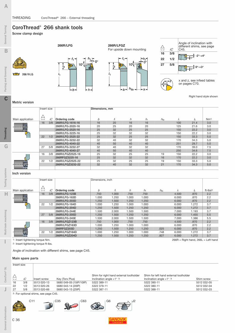
C 36
THREADING CoroThread® 266 – External threading
B
Gen
eral
Tur
ning
Par
ting
and
Gro
ovin
g
C
Thre
adin
g
G
Tool
ing
syst
ems
Mul
ti-ta
sk m
achi
ning
I
Cor
oTur
n® S
L
J
Gen
eral
info
rmat
ion
A
H
C
Thre
adin
g
THREADING CoroThread® 266 – External threading
CoroThread® 266 shank toolsScrew clamp design
Metric version
Inch version
Main spare parts
266R/LFG 266R/LFGZFor upside down mounting
Right hand style shown
Insert size Dimensions, mm
Main application D iC Ordering code b f1 h h1 h5b l1 l3 Nm1)
16 3/8 266R/LFG-1616-16 16 20 16 16 100 21.4 3.0266R/LFG-2020-16 20 25 20 20 125 21.6 3.0266R/LFG-2525-16 25 32 25 25 150 22.2 3.0266R/LFG-3225-16 25 32 32 32 150 22.2 3.0
22 1/2 266R/LFG-2525-22 25 32 25 25 150 33.3 5.0266R/LFG-3232-22 32 40 32 32 170 34.3 5.0266R/LFG-4040-22 40 50 40 40 251 29.7 5.0
27 5/8 266R/LFG-3232-27 32 40 32 32 170 39.0 7.5266R/LFG-4040-27 40 50 40 40 250 34.6 7.5
16 3/8 266R/LFGZ2525-16 25 32 25 25 19 150 22.2 3.0266RFGZ3225-16 25 32 32 32 16 170 22.2 3.0
22 1/2 266R/LFGZ2525-22 25 32 25 25 19 150 33.3 5.0266R/LFGZ3232-22 32 40 32 32 21 170 34.3 5.0
Insert size Dimensions, inch
Main application D iC Ordering code b f1 h h1 h5b l1 l3 ft-lbs2)
16 3/8 266R/LFG-123B .750 1.000 .750 .750 4.500 .870 2.2266R/LFG-163D 1.000 1.250 1.000 1.000 6.000 .870 2.2266R/LFG-203D 1.250 1.500 1.250 1.250 6.000 .870 2.2
22 1/2 266R/LFG-164D 1.000 1.250 1.000 1.000 6.000 1.272 3.7266R/LFG-204D 1.250 1.500 1.250 1.250 6.000 1.272 3.7266R/LFG-244E 1.500 2.000 1.500 1.500 7.000 1.193 3.7
27 5/8 266R/LFG-205D 1.250 1.500 1.250 1.250 6.000 1.455 5.5266R/LFG-245E 1.500 2.000 1.500 1.500 7.000 1.386 5.5
16 3/8 266R/LFGZ123B .750 1.000 .750 .750 4.500 .870 2.2266R/LFGZ163D 1.000 1.250 1.000 1.000 6.000 .870 2.2266RFGZ203D 1.250 1.500 1.250 1.250 .025 6.000 .870 2.2
22 1/2 266R/LFGZ164D 1.000 1.250 1.000 1.000 .748 6.000 1.272 3.7266R/LFGZ204D 1.250 1.500 1.250 1.250 .827 6.000 1.272 3.7
1) Insert tightening torque Nm. 266R = Right hand, 266L = Left hand2) Insert tightening torque ft-lbs.
Angle of inclination with different shims, see page C45.
Insert size
D iC Insert screw Key (Torx Plus)Shim for right hand external toolholder Shim for left hand external toolholder
Shim screwInclination angle +1° 3) Inclination angle +1° 3)
16 3/8 5513 020-13 5680 049-05 (15IP/10IP) 5322 389-11 5322 390-11 5512 032-0522 1/2 5513 020-26 5680 043-14 (20IP) 5322 379-11 5322 380-11 5512 032-0427 5/8 5513 020-66 5680 043-15 (25IP) 5322 387-11 5322 388-11 5512 032-033) For optional shims, see page C45.
D iC
Angle of inclination with different shims, see page C45.
16 3/8
22 1/2
27 5/8
x and z, see infeed tables on pages C70.
C11 C35 C63 G6 J2

B
C 37
Gen
eral
Tur
ning
Par
ting
and
Gro
ovin
g
C
Thre
adin
g
G
Tool
ing
syst
ems
Mul
ti-ta
sk m
achi
ning
I
Cor
oTur
n® S
L
J
Gen
eral
info
rmat
ion
A
H
C
Thre
adin
g
CoroThread® 266 – External threading THREADING
THREADING CoroThread® 266 – External threading
CoroThread® 266 shank toolsTool holders for Swiss machinesScrew clamp design
Metric version
Inch version
Main spare parts
266R/LFA
Threading of slender components and against live centre
Right hand style shown
Insert size Dimensions, mm
Main application D iC Ordering code b f1 h h1 l1 l3 Nm1)
16 3/8 266R/LFA-1010-16-S 10 10 10 10 125 19.8 3.0266R/LFA-1212-16-S 12 12 12 12 125 21.3 3.0266R/LFA-1616-16-S 16 16 16 16 125 23.3 3.0
Insert size Dimensions, inch
Main application D iC Ordering code b f1 h h1 l1 l3 ft-lbs2)
16 3/8 266R/LFA-063-S .375 .375 .375 .375 5.000 .841 2.2266R/LFA-083-S .500 .500 .500 .500 5.000 .841 2.2266R/LFA-103-S .625 .625 .625 .625 5.000 .841 2.2266R/LFA-123-S .750 .750 .750 .750 5.000 .841 2.2
1) Insert tightening torque Nm. R = Right hand, L = Left hand2) Insert tightening torque ft-lbs.
Insert size
D iC Insert screw Key (Torx Plus)Shim for right hand external toolholder Shim for left hand external toolholder
Shim screwInclination angle +1° 3) Inclination angle +1° 3)
16 3/8 5513 020-13 5680 049-05 (15IP/10IP) 5322 389-11 5322 390-11 5512 032-053) For optional shims, see page C45.
D iCAngle of inclination from –2° to +4° with different shims, see page C45.
16 3/8
x and z, see infeed tables on pages C70.
C11 C35 C63 G6 J2
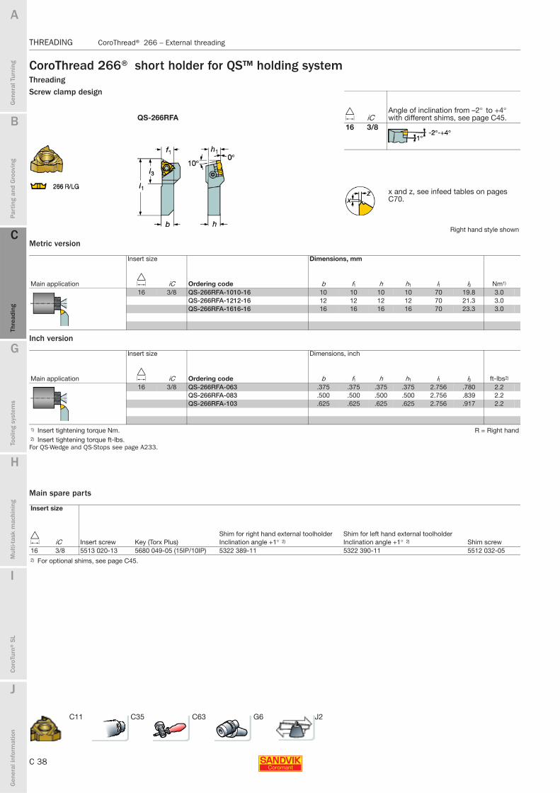
C 38
THREADING CoroThread® 266 – External threading
B
Gen
eral
Tur
ning
Par
ting
and
Gro
ovin
g
C
Thre
adin
g
G
Tool
ing
syst
ems
Mul
ti-ta
sk m
achi
ning
I
Cor
oTur
n® S
L
J
Gen
eral
info
rmat
ion
A
H
C
Thre
adin
g
THREADING CoroThread® 266 – External threading
CoroThread 266® short holder for QS™ holding systemThreadingScrew clamp design
Metric version
Inch version
For QS-Wedge and QS-Stops see page A233.
Main spare parts
QS-266RFA
Right hand style shown
Insert size Dimensions, mm
Main application D iC Ordering code b f1 h h1 l1 l3 Nm1)
16 3/8 QS-266RFA-1010-16 10 10 10 10 70 19.8 3.0QS-266RFA-1212-16 12 12 12 12 70 21.3 3.0QS-266RFA-1616-16 16 16 16 16 70 23.3 3.0
Insert size Dimensions, inch
Main application D iC Ordering code b f1 h h1 l1 l3 ft-lbs2)
16 3/8 QS-266RFA-063 .375 .375 .375 .375 2.756 .780 2.2QS-266RFA-083 .500 .500 .500 .500 2.756 .839 2.2QS-266RFA-103 .625 .625 .625 .625 2.756 .917 2.2
1) Insert tightening torque Nm. R = Right hand2) Insert tightening torque ft-lbs.
Insert size
D iC Insert screw Key (Torx Plus)Shim for right hand external toolholder Shim for left hand external toolholder
Shim screwInclination angle +1° 2) Inclination angle +1° 2)
16 3/8 5513 020-13 5680 049-05 (15IP/10IP) 5322 389-11 5322 390-11 5512 032-052) For optional shims, see page C45.
D iCAngle of inclination from –2° to +4° with different shims, see page C45.
16 3/8
x and z, see infeed tables on pages C70.
C11 C35 C63 G6 J2

B
C 39
Gen
eral
Tur
ning
Par
ting
and
Gro
ovin
g
C
Thre
adin
g
G
Tool
ing
syst
ems
Mul
ti-ta
sk m
achi
ning
I
Cor
oTur
n® S
L
J
Gen
eral
info
rmat
ion
A
H
C
Thre
adin
g
CoroThread® 266 – Internal threading THREADING
THREADING CoroThread® 266 – Internal threading
CoroThread® 266 Coromant Capto® cutting unitsScrew clamp design Steel bar with internal cutting fluid supply
Main spare parts
Cx-266R/LKF
Right hand style shown
Insert size Dimensions, mm, inch
Main application D iC Ordering code D1 Dm min D5m f1 l1 l3 γ n Nm1)
16 3/8 C3-266R/LKF-14060-16 18.5 25 32 14.0 60 44 -15° 3.0.728 .984 1.260 .551 2.362 1.732
C4-266R/LKF-14060-16 18.5 25 40 14.0 60 38 -15° 3.0.728 .984 1.575 .551 2.362 1.496
C4-266R/LKF-17070-16 24.5 32 40 17.0 70 48 -15° 3.0.965 1.260 1.575 .669 2.756 1.890
C4-266RKF-22090-16 32.0 40 40 22.0 90 69 -15° 3.01.260 1.575 1.575 .866 3.543 2.716
C5-266R/LKF-14060-16 18.5 25 50 14.0 60 36 -15° 3.0.728 .984 1.968 .551 2.362 1.417
C5-266R/LKF-17070-16 24.5 32 50 17.0 70 47 -15° 3.0.965 1.260 1.968 .669 2.756 1.850
C5-266R/LKF-22090-16 32.0 40 50 22.0 90 68 -15° 3.01.260 1.575 1.968 .866 3.543 2.677
C5-266R/LKF-27105-16 40.0 50 50 27.0 105 84 -15° 3.01.575 1.968 1.968 1.063 4.134 3.307
C6-266R/LKF-14070-16 18.5 25 63 14.0 70 42 -15° 3.0.728 .984 2.480 .551 2.756 1.654
C6-266R/LKF-17075-16 24.5 32 63 17.0 75 48 -15° 3.0.965 1.260 2.480 .669 2.953 1.890
C6-266R/LKF-22090-16 32.0 40 63 22.0 90 64 -15° 3.01.260 1.575 2.480 .866 3.543 2.520
C6-266R/LKF-27105-16 40.0 50 63 27.0 105 80 -15° 3.01.575 1.968 2.480 1.063 4.134 3.150
1) Insert tightening torque Nm. 266R = Right hand, 266L = Left hand
Angle of inclination with different shims, see page C45.
Insert size
D iC Insert screw Key (Torx Plus)Shim for right hand internal tool holder Shim for left hand internal tool holder
Shim screwInclination angle +1° 2) Inclination angle +1° 2)
16 3/8 5513 020-13 5680 049-05 (15IP/10IP) 5322 390-11 5322 389-11 5512 032-052) For optional shims, see page C45.
D iC
Angle of inclination with different shims, see page C45.
16 3/8
x and z, see infeed tables on pages C70.
C11 C41 C64 G6 J2
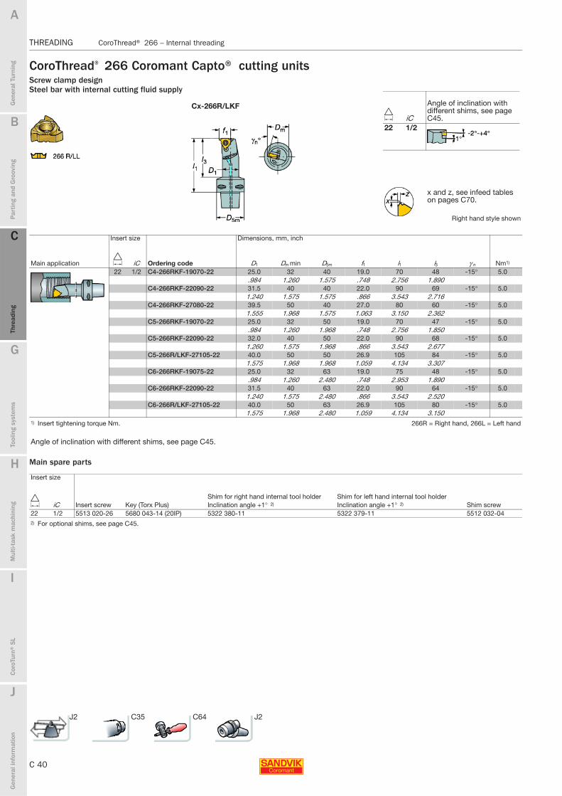
C 40
THREADING CoroThread® 266 – Internal threading
B
Gen
eral
Tur
ning
Par
ting
and
Gro
ovin
g
C
Thre
adin
g
G
Tool
ing
syst
ems
Mul
ti-ta
sk m
achi
ning
I
Cor
oTur
n® S
L
J
Gen
eral
info
rmat
ion
A
H
C
Thre
adin
g
THREADING CoroThread® 266 – Internal threading
CoroThread® 266 Coromant Capto® cutting unitsScrew clamp design Steel bar with internal cutting fluid supply
Main spare parts
Cx-266R/LKF
Right hand style shown
Insert size Dimensions, mm, inch
Main application D iC Ordering code D1 Dm min D5m f1 l1 l3 γ n Nm1)
22 1/2 C4-266RKF-19070-22 25.0 32 40 19.0 70 48 -15° 5.0.984 1.260 1.575 .748 2.756 1.890
C4-266RKF-22090-22 31.5 40 40 22.0 90 69 -15° 5.01.240 1.575 1.575 .866 3.543 2.716
C4-266RKF-27080-22 39.5 50 40 27.0 80 60 -15° 5.01.555 1.968 1.575 1.063 3.150 2.362
C5-266RKF-19070-22 25.0 32 50 19.0 70 47 -15° 5.0.984 1.260 1.968 .748 2.756 1.850
C5-266RKF-22090-22 32.0 40 50 22.0 90 68 -15° 5.01.260 1.575 1.968 .866 3.543 2.677
C5-266R/LKF-27105-22 40.0 50 50 26.9 105 84 -15° 5.01.575 1.968 1.968 1.059 4.134 3.307
C6-266RKF-19075-22 25.0 32 63 19.0 75 48 -15° 5.0.984 1.260 2.480 .748 2.953 1.890
C6-266RKF-22090-22 31.5 40 63 22.0 90 64 -15° 5.01.240 1.575 2.480 .866 3.543 2.520
C6-266R/LKF-27105-22 40.0 50 63 26.9 105 80 -15° 5.01.575 1.968 2.480 1.059 4.134 3.150
1) Insert tightening torque Nm. 266R = Right hand, 266L = Left hand
Angle of inclination with different shims, see page C45.
Insert size
D iC Insert screw Key (Torx Plus)Shim for right hand internal tool holder Shim for left hand internal tool holder
Shim screwInclination angle +1° 2) Inclination angle +1° 2)
22 1/2 5513 020-26 5680 043-14 (20IP) 5322 380-11 5322 379-11 5512 032-042) For optional shims, see page C45.
D iC
Angle of inclination with different shims, see page C45.
22 1/2
x and z, see infeed tables on pages C70.
J2 C35 C64 J2
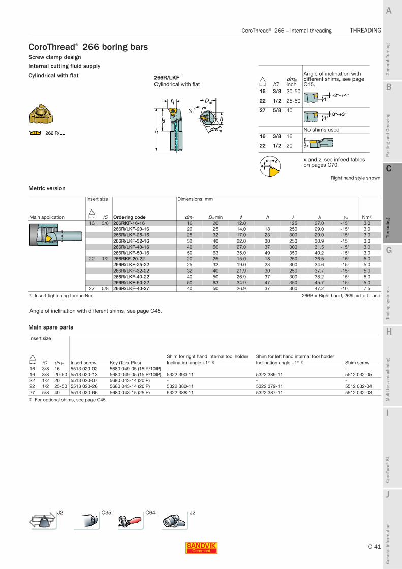
B
C 41
Gen
eral
Tur
ning
Par
ting
and
Gro
ovin
g
C
Thre
adin
g
G
Tool
ing
syst
ems
Mul
ti-ta
sk m
achi
ning
I
Cor
oTur
n® S
L
J
Gen
eral
info
rmat
ion
A
H
C
Thre
adin
g
CoroThread® 266 – Internal threading THREADING
THREADING CoroThread® 266 – Internal threading
CoroThread® 266 boring barsScrew clamp design Internal cutting fluid supply
Metric version
Main spare parts
266R/LKFCylindrical with flat
Right hand style shown
Insert size Dimensions, mm
Main application D iC Ordering code dmm Dm min f1 h l1 l3 γ n Nm1)
16 3/8 266RKF-16-16 16 20 12.0 125 27.0 -15° 3.0266R/LKF-20-16 20 25 14.0 18 250 29.0 -15° 3.0266R/LKF-25-16 25 32 17.0 23 300 29.0 -15° 3.0266R/LKF-32-16 32 40 22.0 30 250 30.9 -15° 3.0266R/LKF-40-16 40 50 27.0 37 300 31.5 -15° 3.0266R/LKF-50-16 50 63 35.0 49 350 40.2 -15° 3.0
22 1/2 266RKF-20-22 20 25 15.0 18 250 36.5 -15° 5.0266R/LKF-25-22 25 32 19.0 23 300 34.6 -15° 5.0266R/LKF-32-22 32 40 21.9 30 250 37.7 -15° 5.0266R/LKF-40-22 40 50 26.9 37 300 38.2 -15° 5.0266R/LKF-50-22 50 63 34.9 47 350 45.7 -15° 5.0
27 5/8 266R/LKF-40-27 40 50 26.9 37 300 47.2 -10° 7.51) Insert tightening torque Nm. 266R = Right hand, 266L = Left hand
Angle of inclination with different shims, see page C45.
Insert size
D iC dmm Insert screw Key (Torx Plus)Shim for right hand internal tool holder Shim for left hand internal tool holder
Shim screwInclination angle +1° 2) Inclination angle +1° 2)
16 3/8 16 5513 020-02 5680 049-05 (15IP/10IP) - - -16 3/8 20-50 5513 020-13 5680 049-05 (15IP/10IP) 5322 390-11 5322 389-11 5512 032-0522 1/2 20 5513 020-07 5680 043-14 (20IP) - - -22 1/2 25-50 5513 020-26 5680 043-14 (20IP) 5322 380-11 5322 379-11 5512 032-0427 5/8 40 5513 020-66 5680 043-15 (25IP) 5322 388-11 5322 387-11 5512 032-032) For optional shims, see page C45.
D iCdmm inch
Angle of inclination with different shims, see page C45.
16 3/8 20-50
22 1/2 25-50
27 5/8 40
No shims used16 3/8 16
22 1/2 20
x and z, see infeed tables on pages C70.
Cylindrical with flat
J2 C35 C64 J2
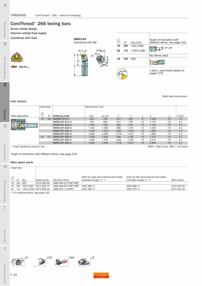
C 42
THREADING CoroThread® 266 – Internal threading
B
Gen
eral
Tur
ning
Par
ting
and
Gro
ovin
g
C
Thre
adin
g
G
Tool
ing
syst
ems
Mul
ti-ta
sk m
achi
ning
I
Cor
oTur
n® S
L
J
Gen
eral
info
rmat
ion
A
H
C
Thre
adin
g
THREADING CoroThread® 266 – Internal threading
CoroThread® 266 boring barsScrew clamp design Internal cutting fluid supply
Inch version
Main spare parts
266R/LKFCylindrical with flat
Right hand style shown
Insert size Dimensions, inch
Main application D iC Ordering code dmm Dm min f1 h l1 l3 γ n ft-lbs1)
16 3/8 266RKF-D10-3 .625 .790 .472 .563 8 1.050 -15° 2.2266R/LKF-D12-3 .750 .980 .551 .709 10 1.140 -15° 2.2266R/LKF-D16-3 1.000 1.260 .669 .910 12 1.140 -15° 2.2266R/LKF-D20-3 1.250 1.580 .866 1.181 14 1.220 -15° 2.2266R/LKF-D24-3 1.500 1.970 1.063 1.378 15 1.260 -15° 2.2266R/LKF-D32-3 2.000 2.480 1.378 1.874 16 1.580 -15° 2.2
22 1/2 266R/LKF-D20-4 1.250 1.580 .866 1.181 14 1.742 -15° 3.7266R/LKF-D24-4 1.500 1.970 1.063 1.378 15 2.012 -15° 3.7266R/LKF-D32-4 2.000 2.480 1.378 1.874 16 2.059 -15° 3.7
1) Insert tightening torque ft-lbs. 266R = Right hand, 266L = Left hand
Angle of inclination with different shims, see page C45.
Insert size
D iC dmm Insert screw Key (Torx Plus)Shim for right hand internal tool holder Shim for left hand internal tool holder
Shim screwInclination angle +1° 2) Inclination angle +1° 2)
16 3/8 .625 5513 020-02 5680 049-05 (15IP/10IP) - - -16 3/8 .750-2.000 5513 020-13 5680 049-05 (15IP/10IP) 5322 390-11 5322 389-11 5512 032-0522 1/2 1.250-2.000 5513 020-26 5680 043-14 (20IP) 5322 380-11 5322 379-11 5512 032-042) For optional shims, see page C45.
D iC dmm inchAngle of inclination with different shims, see page C45.
16 3/8 .750-2.000
22 1/2 1.250-2.000
No shims used16 3/8 .625
x and z, see infeed tables on pages C70.
Cylindrical with flats
J2 C35 C64 J2
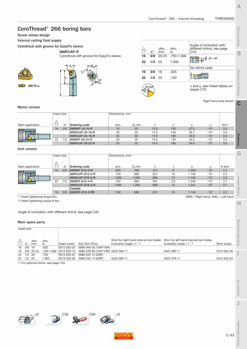
B
C 43
Gen
eral
Tur
ning
Par
ting
and
Gro
ovin
g
C
Thre
adin
g
G
Tool
ing
syst
ems
Mul
ti-ta
sk m
achi
ning
I
Cor
oTur
n® S
L
J
Gen
eral
info
rmat
ion
A
H
C
Thre
adin
g
CoroThread® 266 – Internal threading THREADING
THREADING CoroThread® 266 – Internal threading
CoroThread® 266 boring barsScrew clamp design Internal cutting fluid supply
Metric version
Inch version
Main spare parts
266R/LKF-RCylindrical with groove for EasyFix sleeve
Right hand style shown
Insert size Dimensions, mm
Main application D iC Ordering code dmm Dm min f1 l1 l3 γ n Nm1)
16 3/8 266RKF-16-16-R 16 20 12.0 125 27.0 -15° 3.0266R/LKF-20-16-R 20 25 14.0 140 28.7 -15° 3.0266R/LKF-25-16-R 25 32 17.0 180 28.8 -15° 3.0
22 1/2 266RKF-20-22-R 20 25 15.0 140 34.2 -15° 5.0266R/LKF-25-22-R 25 32 19.0 180 34.6 -15° 5.0
Insert size Dimensions, inch
Main application D iC Ordering code dmm Dm min f1 l1 l3 γ n ft-lbs2)
16 3/8 266RKF-D10-3-R .625 .790 .472 8 1.050 -15° 2.2266R/LKF-D12-3-R .750 .980 .551 10 1.140 -15° 2.2266R/LKF-D16-3-R 1.000 1.260 .669 12 1.140 -15° 2.2
22 1/2 266RKF-D12-4-R .750 .984 .591 5.5 1.346 -15° 3.7266R/LKF-D16-4-R 1.000 1.260 .669 12 1.341 -15° 3.7Carbide
16 3/8 266RKF-D12-3-RE .750 .980 .551 10 1.140 -15° 2.21) Insert tightening torque Nm. 266R = Right hand, 266L = Left hand2) Insert tightening torque ft-lbs.
Angle of inclination with different shims, see page C45.
Insert size
D iCdmmmm
dmmin. Insert screw Key (Torx Plus)
Shim for right hand internal tool holder Shim for left hand internal tool holderShim screwInclination angle +1° 3) Inclination angle +1° 3)
16 3/8 16 .625 5513 020-02 5680 049-05 (15IP/10IP) - - -16 3/8 20-25 .750-1.000 5513 020-13 5680 049-05 (15IP/10IP) 5322 390-11 5322 389-11 5512 032-0522 1/2 20 .750 5513 020-07 5680 043-14 (20IP) - - -22 1/2 25 1.000 5513 020-26 5680 043-14 (20IP) 5322 380-11 5322 379-11 5512 032-043) For optional shims, see page C45.
D iCdmmmm
dmmin.
Angle of inclination with different shims, see page C45.
16 3/8 20-25 .750-1.000
22 1/2 25 1.000
No shims used16 3/8 16 .625
22 1/2 20 .750
x and z, see infeed tables on pages C70.
Cylindrical with groove for EasyFix sleeve
J2 C35 C64 J2

C 44
THREADING CoroThread® 266 – Internal threading
B
Gen
eral
Tur
ning
Par
ting
and
Gro
ovin
g
C
Thre
adin
g
G
Tool
ing
syst
ems
Mul
ti-ta
sk m
achi
ning
I
Cor
oTur
n® S
L
J
Gen
eral
info
rmat
ion
A
H
C
Thre
adin
g
THREADING CoroThread® 266 – Internal threading
CoroThread® 266 cartridgesScrew clamp design
Main spare parts
Mounting dimensions for cartridges
Right hand style shown
Insert size Dimensions, mm, inch
Main application D iC Ordering code Dm min b f1 l1 h l8 γ n Nm1)
16 3/8 266R/LKF-16CA-16 55 19 25.0 63 21 38 -15° 3.02.165 .748 .984 2.480 .827 1.496
22 1/2 266R/LKF-20CA-22 60 16 25.0 70 21 40 -15° 5.02.362 .630 .984 2.756 .827 1.575
1) Insert tightening torque Nm.
Angle of inclination with different shims, see page C45.
Insert size
D iC Insert screw Key (Torx Plus)Shim for right hand internal tool holder Shim for left hand internal tool holder
Shim screwInclination angle +1° 2) Inclination angle +1° 2)
16 3/8 5513 020-13 5680 049-05 (15IP/10IP) 5322 390-11 5322 389-11 5512 032-0522 1/2 5513 020-26 5680 043-14 (20IP) 5322 380-11 5322 379-11 5512 032-042) For optional shims, see page C45.
16CA
20CA
Angle of inclination from –2° to +4° with different shims, see page C45.
Dimensions, mm, inch
Cartridge codeDm D1
xl21
l22 h1
bc
min min min max266R/LKF-16CA-16 55 50 4.47 35 60 16 15
2.165 1.969 .176 1.378 2.362 .630 .591266R/LKF-20CA-22 60 55 6.63 37 67 20 12.2
2.362 2.165 .261 1.460 2.638 .787 .480
D iC
Angle of inclination with different shims, see page C45.
16 3/8
22 1/2
x and z, see infeed tables on pages C70.
J2 C35 C64 J2

B
C 45
Gen
eral
Tur
ning
Par
ting
and
Gro
ovin
g
C
Thre
adin
g
G
Tool
ing
syst
ems
Mul
ti-ta
sk m
achi
ning
I
Cor
oTur
n® S
L
J
Gen
eral
info
rmat
ion
A
H
C
Thre
adin
g
CoroThread® 266 – Selecting shims THREADING
THREADING CoroThread® 266 – Selecting shims
Selecting shims
The angle of inclination is calculated by using the formula:
P = Pitchd2 = Effective diameter of threadλ = Angle of inclination
Pitch range Insert size Inclination angle Shims
For right hand external toolFor left hand internal tool
For left hand external toolFor right hand internal tool
mm D iC(TPI)
0.5-3.0 16 3/8 –2° 5322 389-22 5322 390-22(32-6) –1° 5322 389-21 5322 390-21
0° 5322 389-10 5322 390-101° 5322 389-111) 5322 390-111)
2° 5322 389-12 5322 390-123° 5322 389-13 5322 390-134° 5322 389-14 5322 390-14
2.5–7.0 22 1/2 –2° 5322 379-22 5322 380-22(11.5-4) –1° 5322 379-21 5322 380-21
0° 5322 379-10 5322 380-101° 5322 379-111) 5322 380-111)
2° 5322 379-12 5322 380-123° 5322 379-13 5322 380-134° 5322 379-14 5322 380-14
8.0 27 5/8 0° 5322 387-10 5322 388-10(5-3) 1° 5322 387-111) 5322 388-111)
2° 5322 387-12 5322 388-123° 5322 387-13 5322 388-134° 5322 387-14 5322 388-14
1) Delivered with the tool.Note!The last two figures in the shim code indicate + or - and the effective inclination angle with the shim mounted in the holder.e.g. 5322 379-11 = angle + 1° and 5322 379-21 = angle - 1° .
Workpiecediameter
mm inch
Threads/inchLead (Pitch) mm
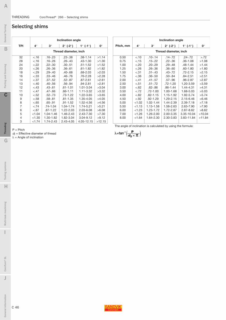
C 46
THREADING CoroThread® 266 – Selecting shims
B
Gen
eral
Tur
ning
Par
ting
and
Gro
ovin
g
C
Thre
adin
g
G
Tool
ing
syst
ems
Mul
ti-ta
sk m
achi
ning
I
Cor
oTur
n® S
L
J
Gen
eral
info
rmat
ion
A
H
C
Thre
adin
g
THREADING CoroThread® 266 – Selecting shims
Selecting shims
Inclination angle
Pitch, mm
Inclination angle
TPI 4° 3° 2° (-2° ) 1° (-1° ) 0° 4° 3° 2° (-2° ) 1° (-1° ) 0°
Thread diameter, inch Thread diameter, inch
32 <.16 .16-.23 .23-.38 .38-1.14 >1.14 0.50 <.10 .10-.14 .14-.72 .24-.72 >.7228 <.16 .16-.26 .26-.43 .43-1.30 >1.30 0.75 <.15 .15-.22 .22-.36 .36-1.08 >1.0824 <.22 .22-.30 .30-.51 .51-1.52 >1.52 1.00 <.20 .20-.29 .29-.48 .48-1.44 >1.4420 <.26 .26-.36 .36-.61 .61-1.82 >1.82 1.25 <.26 .26-.36 .36-.60 .60-1.80 >1.8018 <.29 .29-.40 .40-.68 .68-2.03 >2.03 1.50 <.31 .31-.43 .43-.72 .72-2.15 >2.1516 <.33 .33-.46 .46-.76 .76-2.28 >2.28 1.75 <.36 .36-.50 .50-.84 .84-2.51 >2.5114 <.37 .37-.52 .52-.87 .87-2.61 >2.61 2.00 <.41 .41-.57 .57-.96 .96-2.87 >2.8713 <.40 .40-.56 .56-.94 .94-2.81 >2.81 2.50 <.51 .51-.72 .72-1.20 1.20-3.59 >3.5912 <.43 .43-.61 .61-1.01 1.01-3.04 >3.04 3.00 <.62 .62-.86 .86-1.44 1.44-4.31 >4.3111 <.47 .47-.66 .66-1.11 1.11-3.32 >3.32 3.50 <.72 .72-1.00 1.00-1.68 1.68-5.03 >5.0310 <.52 .52-.73 .73-1.22 1.22-3.65 >3.65 4.00 <.82 .82-1.15 1.15-1.92 1.92-5.74 >5.749 <.58 .58-.81 .81-1.35 1.35-4.05 >4.05 4.50 <.92 .92-1.29 1.29-2.15 2.15-6.46 >6.468 <.65 .65-.91 .91-1.52 1.52-4.56 >4.56 5.00 <1.02 1.02-1.44 1.44-2.39 2.39-7.18 >7.187 <.74 .74-1.04 1.04-1.74 1.74-5.21 >5.21 5.50 <1.13 1.13-1.58 1.58-2.63 2.63-7.90 >7.906 <.87 .87-1.22 1.22-2.03 2.03-6.08 >6.08 6.00 <1.23 1.23-1.72 1.72-2.87 2.87-8.62 >8.625 <1.04 1.04-1.46 1.46-2.43 2.43-7.30 >7.30 7.00 <1.26 1.26-2.00 2.00-3.35 3.35-10.04 >10.044 <1.30 1.30-1.82 1.82-3.04 3.04-9.12 >9.12 8.00 <1.64 1.64-2.30 2.30-3.83 3.83-11.84 >11.843 <1.74 1.74-2.43 2.43-4.05 4.05-12.15 >12.15
The angle of inclination is calculated by using the formula:P = Pitchd2 = Effective diameter of threadλ = Angle of inclination
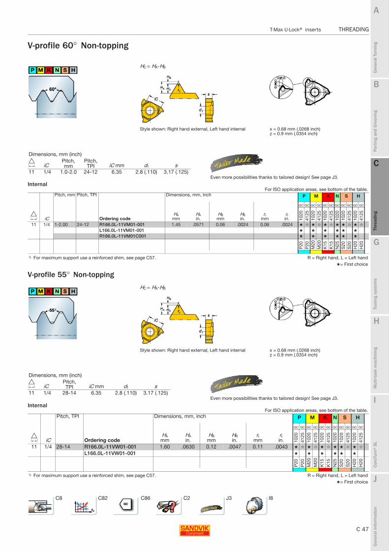
B
C 47
Gen
eral
Tur
ning
Par
ting
and
Gro
ovin
g
C
Thre
adin
g
G
Tool
ing
syst
ems
Mul
ti-ta
sk m
achi
ning
I
Cor
oTur
n® S
L
J
Gen
eral
info
rmat
ion
A
H
C
Thre
adin
g
T-Max U-Lock® inserts THREADING
THREADING T-Max U-Lock® inserts
V-profile 60° Non-topping
Internal
V-profile 55° Non-topping
Internal
HC = HA-HB
Style shown: Right hand external, Left hand internal x = 0.68 mm (.0268 inch)z = 0.9 mm (.0354 inch)
Pitch, mm Pitch, TPI Dimensions, mm, inch P M K N S H
D iC Ordering codeHA
mmHAin.
HBmm
HBin.
rεmm
rεin.
GC GC GC GC GC GC GC GC GC GC GC
1020
4125
1020
4125
1020
4125
1020
1020
4125
1020
4125
11 1/4 1-2.00 24-12 R166.0L-11VM01-001 1.45 .0571 0.06 .0024 0.06 .0024 ★ ✩ ★ ✩ ★ ✩ ★ ★ ✩ ★ ✩
L166.0L-11VM01-001 ★ ★ ★ ★ ★ ★
R166.0L-11VM01C001 ★ ★ ★ ★ ★ ★
P20
P20
M20
M20
K15
K15
N25
S20
S20
H20
H20
1) For maximum support use a reinforced shim, see page C57. R = Right hand, L = Left hand★= First choice
HC = HA-HB
Style shown: Right hand external, Left hand internal x = 0.68 mm (.0268 inch)z = 0.9 mm (.0354 inch)
Pitch, TPI Dimensions, mm, inch P M K N S H
D iC Ordering codeHA
mmHAin.
HBmm
HBin.
rεmm
rεin.
GC GC GC GC GC GC GC GC GC GC GC
1020
4125
1020
4125
1020
4125
1020
1020
4125
1020
4125
11 1/4 28-14 R166.0L-11VW01-001 1.60 .0630 0.12 .0047 0.11 .0043 ★ ✩ ★ ✩ ★ ✩ ★ ★ ✩ ★ ✩
L166.0L-11VW01-001 ★ ★ ★ ★ ★ ★
P20
P20
M20
M20
K15
K15
N25
S20
S20
H20
H20
1) For maximum support use a reinforced shim, see page C57. R = Right hand, L = Left hand★= First choice
Dimensions, mm (inch)
D iCPitch, mm
Pitch, TPI iC mm d1 s
11 1/4 1.0-2.0 24-12 6.35 2.8 (.110) 3.17 (.125)Even more possibilities thanks to tailored design! See page J3.
For ISO application areas, see bottom of the table.
Dimensions, mm (inch)
D iCPitch, TPI iC mm d1 s
11 1/4 28-14 6.35 2.8 (.110) 3.17 (.125)Even more possibilities thanks to tailored design! See page J3.
For ISO application areas, see bottom of the table.
C8 C82 C86 C2 J3 I8

C 48
THREADING T-Max U-Lock® inserts
B
Gen
eral
Tur
ning
Par
ting
and
Gro
ovin
g
C
Thre
adin
g
G
Tool
ing
syst
ems
Mul
ti-ta
sk m
achi
ning
I
Cor
oTur
n® S
L
J
Gen
eral
info
rmat
ion
A
H
C
Thre
adin
g
THREADING T-Max U-Lock® inserts
Metric 60° Full form Threads for general usage in all segments of engineering industry.
Internal
Single-point
ISO 965-1998 Tolerance class 6 Style shown: Right hand external, Left hand internal
Pitch, mm Dimensions, millimeter, inch (mm, in.) P M K N S H
D iC Ordering codeHA
mmHAin.
HBmm
HBin. x mm x in. z mm z in.
GC GC GC GC GC GC GC GC GC GC GC
1020
4125
1020
4125
1020
4125
1020
1020
4125
1020
4125
11 1/4 0.50 R/L166.0L-11MM01-050 0.32 .0126 0.03 .0012 0.68 .0268 0.5 .0197 ★ ★ ★ ★ ★ ★
0.75 R/L166.0L-11MM01-075 0.47 .0185 0.04 .0016 0.68 .0268 0.6 .0236 ★ ★ ★ ★ ★ ★
1.00 R166.0L-11MM01-100 0.64 .0252 0.06 .0024 0.68 .0268 0.8 0.315 ★ ✩ ★ ✩ ★ ✩ ★ ★ ✩ ★ ✩
L166.0L-11MM01-100 ★ ★ ★ ★ ★ ★
1.25 R/L166.0L-11MM01-125 0.79 .0311 0.07 .0028 0.68 .0268 0.8 .0314 ★ ★ ★ ★ ★ ★
1.50 R166.0L-11MM01-150 0.96 .0378 0.09 .0035 0.68 .0268 1.1 .0433 ★ ✩ ★ ✩ ★ ✩ ★ ★ ✩ ★ ✩
L166.0L-11MM01-150 ★ ★ ★ ★ ★ ★
1.75 R/L166.0L-11MM01-175 1.11 .0437 0.11 .0043 0.68 .0268 1.05 .0413 ★ ★ ★ ★ ★ ★
2.00 R166.0L-11MM01-200 1.27 .0500 0.12 .0047 0.58 .0228 0.92 .0362 ★ ✩ ★ ✩ ★ ✩ ★ ★ ✩ ★ ✩
L166.0L-11MM01-200 ★ ★ ★ ★ ★ ★
P20
P20
M20
M20
K15
K15
N25
S20
S20
H20
H20
R = Right hand, L = Left hand★= First choice
Dimensions, mm (inch)
D iCPitch, mm iC mm d1 s
11 1/4 0.5-2.0 6.35 2.8 (.110) 3.17 (.125)Even more possibilities thanks to tailored design! See page J3.
For ISO application areas, see bottom of the table.
C8 C82 C86 C2 J3 v

B
C 49
Gen
eral
Tur
ning
Par
ting
and
Gro
ovin
g
C
Thre
adin
g
G
Tool
ing
syst
ems
Mul
ti-ta
sk m
achi
ning
I
Cor
oTur
n® S
L
J
Gen
eral
info
rmat
ion
A
H
C
Thre
adin
g
T-Max U-Lock® inserts THREADING
THREADING T-Max U-Lock® inserts
UN 60° Full formThreads for general usage in all segments of engineering industry.
Internal
Single-point
ISO 5864-1978Tolerance class 2B, int.
Style shown: Right hand external, Left hand internalTolerance class 2A, ext.
Pitch, TPI Dimensions, millimeter, inch (mm, in.) P M K N S H
D iC Ordering codeHA
mmHAin.
HBmm
HBin. x mm x in. z mm z in.
GC GC GC GC GC GC
1020
1020
1020
1020
1020
1020
11 1/4 32 R/L166.0L-11UN01-320 0.50 .0197 0.04 .0016 0.68 .0268 0.6 .0236 ★ ★ ★ ★ ★ ★
28 R/L166.0L-11UN01-280 0.58 .0228 0.05 .0020 0.8 .0315 ★ ★ ★ ★ ★ ★
24 R/L166.0L-11UN01-240 0.67 .0264 0.06 .0024 0.85 .0335 ★ ★ ★ ★ ★ ★
20 R/L166.0L-11UN01-200 0.80 .0315 0.07 .0028 0.9 .0354 ★ ★ ★ ★ ★ ★
18 R/L166.0L-11UN01-180 0.89 .0350 0.08 .0031 1.0 .0394 ★ ★ ★ ★ ★ ★
16 R/L166.0L-11UN01-160 1.00 .0394 0.09 .0035 1.0 .0394 ★ ★ ★ ★ ★ ★
14 R/L166.0L-11UN01-140 1.13 .0445 0.11 .0043 1.05 .0413 ★ ★ ★ ★ ★ ★
P20
M20
K15
N25
S20
H20
R = Right hand, L = Left hand
★= First choice
Dimensions, mm (inch)
D iCPitch, TPI iC mm d1 s
11 1/4 32-14 6.35 2.8 (.110) 3.17 (.125)Even more possibilities thanks to tailored design! See page J3.
For ISO application areas, see bottom of the table.
C8 C82 C86 C2 J3 I8

C 50
THREADING T-Max U-Lock® inserts
B
Gen
eral
Tur
ning
Par
ting
and
Gro
ovin
g
C
Thre
adin
g
G
Tool
ing
syst
ems
Mul
ti-ta
sk m
achi
ning
I
Cor
oTur
n® S
L
J
Gen
eral
info
rmat
ion
A
H
C
Thre
adin
g
THREADING T-Max U-Lock® inserts
Whitworth 55° (BSW, BSF, BSP) Full formThreads for pipe fittings and couplings for gas, water and sewage.
Internal
Threads for pipe fittings and couplings for gas, water and sewage.
Single-point
ISO 228-1982 Pipe threads 55°BS 2779-1973 External: G threadBS 84-1956 Internal: G/Rp threadsClass A tolerance Style shown: Right hand external, Left hand internal
Pitch, TPI Dimensions, millimeter, inch (mm, in.) P M K N S H
D iC Ordering codeHA
mmHAin.
HBmm
HBin. x mm x in. z mm z in.
GC GC GC GC GC GC GC GC GC GC GC
1020
4125
1020
4125
1020
4125
1020
1020
4125
1020
4125
11 1/4 20 R/L166.0L-11WH01-200 0.99 .0390 0.17 .0067 0.68 .0268 0.9 .0354 ★ ★ ★ ★ ★ ★
19 R166.0L-11WH01-190 1.05 .0413 0.18 .0071 ★ ✩ ★ ✩ ★ ✩ ★ ★ ✩ ★ ✩
L166.0L-11WH01-190 ★ ★ ★ ★ ★ ★
14 R166.0L-11WH01-140 1.43 .0563 0.25 .0098 1.05 .0413 ★ ✩ ★ ✩ ★ ✩ ★ ★ ✩ ★ ✩
L166.0L-11WH01-140 ★ ★ ★ ★ ★ ★
P20
P20
M20
M20
K15
K15
N25
S20
S20
H20
H20
R = Right hand, L = Left hand★= First choice
Single-point
ANSI B.1.20.1-1983 Style shown: Right hand external, Left hand internal
Pitch, TPI Dimensions, millimeter, inch (mm, in.) P M K N S H
D iC Ordering codeHA
mmHAin.
HBmm
HBin.
GC GC GC GC GC GC
1020
1020
1020
1020
1020
1020
11 1/4 18 R166.0L-11NT01F180 1.14 .0449 0.08 .0031 ★ ★ ★ ★ ★ ★
14 R166.0L-11NT01F140 1.46 .0575 0.09 .0035 ★ ★ ★ ★ ★ ★
P20
M20
K15
N25
S20
H20
1) The insert can give a slightly bigger truncation for LINE PIPE 14 t.p.i. R = Right hand, L = Left hand2) For maximum support use a reinforced shim, see page C57. ★= First choice
NPT 60° NPSC, NPTR, LINE PIPE1) Full form
Dimensions, mm (inch)
D iCPitch, TPI iC mm d1 s
11 1/4 20-14 6.35 2.8 (.110) 3.17 (.125)Even more possibilities thanks to tailored design! See page J3.
For ISO application areas, see bottom of the table.
Dimensions, mm (inch)
D iCPitch, TPI iC mm d1 s
11 1/4 18-14 6.35 2.8 (.110) 3.17 (.125)Even more possibilities thanks to tailored design! See page J3.
For ISO application areas, see bottom of the table.
C8 C82 C86 C2 J3 I8

B
C 51
Gen
eral
Tur
ning
Par
ting
and
Gro
ovin
g
C
Thre
adin
g
G
Tool
ing
syst
ems
Mul
ti-ta
sk m
achi
ning
I
Cor
oTur
n® S
L
J
Gen
eral
info
rmat
ion
A
H
C
Thre
adin
g
T-Max U-Lock® – External threading and circlip grooving THREADING
THREADING T-Max U-Lock® – External threading and circlip grooving
T-Max U-Lock®Coromant Capto® cutting unitsWedge clamp design
Main spare parts
Cx-R/L166.5FA Cx-R/L166.5FAZFor upside down mounting
To be used with CoroThread 266 inserts
Threading of slender components and against live centre Right hand style shown
Insert size Dimensions, millimeter, inch (mm, in.)
Main application D iC Ordering codeD5mmm
D5min.
f1mm
f1in.
l1mm
l1in. Nm1)
16 3/8 C3-R/L166.5FA-17039-16 32 1.260 17 .669 39 1.535 1.7C4-R/L166.5FA-21055-16 40 1.575 21 .827 55 2.165 1.7C5-R/L166.5FA-26065-16 50 1.968 26 1.024 65 2.559 1.7C6-R/L166.5FA-33075-16 63 2.480 33 1.299 75 2.953 1.7
16 3/8 C3-R166.5FAZ17039-16 32 1.260 17 .669 39 1.535 1.7C4-R166.5FAZ21055-16 40 1.575 21 .827 55 2.165 1.7C5-R166.5FAZ26065-16 50 1.968 26 1.024 65 2.559 1.7C6-R166.5FAZ33075-16 63 2.480 33 1.299 75 2.953 1.7
1) Insert tightening torque Nm. R = Right hand, L = Left hand
Insert size
Shims1)
Inclination angle +1°D iC Wedge set Centre pin Key (Torx Plus) Right hand Left hand16 3/8 5431 126-011 5313 033-01 5680 051-03 (9IP) 5322 371-11 5322 372-111) For optional shims, see page C57.
D iC
Angle of inclination with different shims, see page C45.
16 3/8
x and z, see infeed tables on pages C70.
C4 C52 C65 G6 C2 J2

C 52
THREADING T-Max U-Lock® – External threading and circlip grooving
B
Gen
eral
Tur
ning
Par
ting
and
Gro
ovin
g
C
Thre
adin
g
G
Tool
ing
syst
ems
Mul
ti-ta
sk m
achi
ning
I
Cor
oTur
n® S
L
J
Gen
eral
info
rmat
ion
A
H
C
Thre
adin
g
THREADING T-Max U-Lock® – External threading and circlip grooving
T-Max U-Lock® shank toolsWedge clamp designThreading of slender components and against live centre
Metric version
Inch version
Main spare parts
R/L166.5FA
To be used with CoroThread 266 inserts
Threading of slender components and against live centre Right hand style shown
Insert size Pitch range Dimensions, mm
Main application D iC mm TPI Ordering code b f1 h h1 l1 l3 Nm1)
16 3/8 0.5-3.0 32-6 R/L166.5FA-1212-16 12 12.5 12 12 80 30.4 1.7R/L166.5FA-1616-16 16 16.5 16 16 100 30.4 1.7R/L166.5FA-2020-16 20 20.5 20 20 125 30.4 1.7R/L166.5FA-2525-16 25 25.5 25 25 150 30.4 1.7
Insert size Pitch range Dimensions, inch
Main application D iC mm TPI Ordering code b f1 h h1 l1 l3 ft-lbs2)
16 3/8 0.5-3.0 32-6 R166.5FA-083 .500 .520 .500 .500 3.500 1.200 0.9R/L166.5FA-103 .625 .645 .625 .625 4.000 1.200 0.9R/L166.5FA-123B .750 .770 .750 .750 4.500 1.200 0.9R/L166.5FA-163D 1.000 1.020 1.000 1.000 6.000 1.200 0.9R166.5FA-203D 1.250 1.289 1.250 1.250 6.000 1.200 0.9
1) Insert tightening torque Nm. R = Right hand, L = Left hand2) Insert tightening torque ft-lbs.
Insert size
Shim3)
Inclination angle +1°D Key (Torx Plus)iC Wedge set Centre pin Right hand Left hand16 3/8 5431 126-011 5313 033-01 5680 051-03 (9IP) 5322 371-11 5322 372-113) For optional shims, see page C57.
D iC
Angle of inclination with different shims, see page C45.
16 3/8
x and z, see infeed tables on pages C70.
C4 C51 C66 G6 C2 J2

B
C 53
Gen
eral
Tur
ning
Par
ting
and
Gro
ovin
g
C
Thre
adin
g
G
Tool
ing
syst
ems
Mul
ti-ta
sk m
achi
ning
I
Cor
oTur
n® S
L
J
Gen
eral
info
rmat
ion
A
H
C
Thre
adin
g
T-Max U-Lock® – Internal threading and circlip grooving THREADING
THREADING T-Max U-Lock® – Internal threading and circlip grooving
T-Max U-Lock®Coromant Capto® cutting unitsScrew clamp design Steel bar with internal cutting fluid supply
For upside down mounting
Main spare parts
Right hand style shown
Insert size Pitch range Dimensions, mm, inch
Main application D iC mm TPI Ordering code D1 Dm min D5m f1 l1 l3 Nm1)
11 1/4 0.5-2.0 32-12 C3-R/L166.0KF-12050-11 16.0 20 32 12 50 33 0.9.630 .787 1.260 .472 1.969 1.299 0.9
C4-R/L166.0KF-12060-11 16.0 20 40 12 60 37 0.9.630 .787 1.575 .472 2.362 1.457 0.9
1) Insert tightening torque Nm. R = Right hand, L = Left hand
Right hand style shown
Insert size Pitch range Dimensions, mm, inch
Main application D iC mm TPI Ordering code D1 Dm min D5m f1 l1 l3 Nm1)
11 1/4 0.5-2.0 32-12 C3-R166.0KFZ12050-11 16.0 20 32 12 50 33 0.9.630 .787 1.260 .472 1.969 1.299 0.9
C4-R166.0KFZ12060-11 16.0 20 40 12 60 37 0.9.630 .787 1.575 .472 2.362 1.457 0.9
1) Insert tightening torque Nm. R = Right hand, L = Left hand
Insert size
D iC D1 Insert screw Key (Torx Plus)11 1/4 .630 5513 020-03 5680 051-02 (7IP)
D iC No shims used.11 1/4
x and z values, see T-Max U-Lock insert pages on C70.
C4 C55 C66 G6 C2 v
D iC No shims used.11 1/4
x and z values, see T-Max U-Lock insert pages on C70.

C 54
THREADING T-Max U-Lock® – Internal threading and circlip grooving
B
Gen
eral
Tur
ning
Par
ting
and
Gro
ovin
g
C
Thre
adin
g
G
Tool
ing
syst
ems
Mul
ti-ta
sk m
achi
ning
I
Cor
oTur
n® S
L
J
Gen
eral
info
rmat
ion
A
H
C
Thre
adin
g
THREADING T-Max U-Lock® – Internal threading and circlip grooving
T-Max U-Lock® boring barsScrew clamp design Cylindrical with flat
Metric version
Inch version
Main spare parts
R166.0KF
Insert size Pitch range Dimensions, mm
Main application D iC mm TPI Ordering code dmm Dm min f1 h l1 l3 γ n Nm1)
11 1/4 0.5-2.0 32-12 R/L166.0KF-16-1220-11B 16 12 10 15 125 20.9 -15 0.9R/L166.0KF-16-1625-11B 16 16 10.5 15 150 25.9 -15 0.9
Insert size Pitch range Dimensions, inch
Main application D iC mm TPI Ordering code dmm Dm min f1 h l1 l3 γ n ft-lbs2)
11 1/4 0.5-2.0 32-12 R/L166.0KF-D10-D0812-2B 0.625 0.5 .394 .570 5.000 .820 -15 0.7R166.0KF-D10-D1016-2B 0.625 0.63 .413 .563 6.000 1.030 -15 0.7
1) Insert tightening torque Nm. R = Right hand, L = Left hand2) Insert tightening torque ft-lbs.
Insert size
D iC Key (Torx Plus)Insert screw11 1/4 5513 020-03 5680 051-02 (7IP)
D iC No shims used.11 1/4
x and z values, see T-Max U-Lock insert pages on C70.
C4 C53 C67 G6 C2 J2

B
C 55
Gen
eral
Tur
ning
Par
ting
and
Gro
ovin
g
C
Thre
adin
g
G
Tool
ing
syst
ems
Mul
ti-ta
sk m
achi
ning
I
Cor
oTur
n® S
L
J
Gen
eral
info
rmat
ion
A
H
C
Thre
adin
g
T-Max U-Lock® – Internal threading and circlip grooving THREADING
THREADING T-Max U-Lock® – Internal threading and circlip grooving
T-Max U-lock® carbide and steel boring barsCylindrical shank
With groove for EasyFix sleeve
Metric version
Inch version
Main spare parts
Screw clamp design R/L166.4KFR166.0KF
Insert size Pitch range Dimensions, mm
Main application D iC mm TPI Ordering code dmm Dm min f1 l1 l3 γ n Nm1)
11 1/4 0.5-2.0 32-12 R166.0KF-10E-11 10 12 7.2 150 21.0 -15 0.9R166.0KF-12E-11 12 16 9 180 25.0 -15 0.9
Insert size Pitch range Dimensions, inch
Main application D iC mm TPI Ordering code dmm Dm min f1 h l1 l3 γ n ft-lbs2)
11 1/4 0.5-2.0 32-12 R/L166.0KF-D06C-2C 0.375 0.5 .295 .359 6.000 .880 -15 0.7R/L166.0KF-D08C-2C 0.5 0.63 .354 .484 8.000 .930 -15 0.7
1) Insert tightening torque Nm. R = Right hand, L = Left hand2) Insert tightening torque ft-lbs.For coolant connector, see page A308.
Insert size
iC D
ØKey (Torx Plus)dmm Insert screw
1/4 11 .625-.630 5513 020-03 5680 051-02 (7IP)
D iC No shims used.11 1/4
x and z values, see T-Max U-Lock insert pages on C70.
C4 C53 C66 G6 C2 J2

C 56
THREADING T-Max U-Lock® – Internal threading and circlip grooving
B
Gen
eral
Tur
ning
Par
ting
and
Gro
ovin
g
C
Thre
adin
g
G
Tool
ing
syst
ems
Mul
ti-ta
sk m
achi
ning
I
Cor
oTur
n® S
L
J
Gen
eral
info
rmat
ion
A
H
C
Thre
adin
g
THREADING T-Max U-Lock® – Internal threading and circlip grooving
T-Max U-Lock® boring barsCylindricalScrew clamp design dedicated for circlip grooves
Cylindrical with flats
Main spare parts
R154.0KF
Cylindrical with flats
x and z, see infeed tables on pages C70.
No shims used.
Right hand style shown
Insert size Pitch range Dimensions, mm, inch
Main application D iC mm TPI Ordering code dmm Dm min f1 h l1 l3 Nm1)
11 1/4 0.5-2.0 32-12 R154.0KF-16-1220-11B 16 12 10 15 125 20.9 0.9.630 .472 .394 .591 4.921 .823 0.9
1) Insert tightening torque Nm. R = Right hand
For coolant connector, see page A308.
Insert size
D Insert screw Key (Torx Plus)11 5513 020-03 5680 051-02 (7IP)
C4 C53 C66 G6 C2 J2

B
C 57
Gen
eral
Tur
ning
Par
ting
and
Gro
ovin
g
C
Thre
adin
g
G
Tool
ing
syst
ems
Mul
ti-ta
sk m
achi
ning
I
Cor
oTur
n® S
L
J
Gen
eral
info
rmat
ion
A
H
C
Thre
adin
g
T-Max U-Lock® Selecting shims THREADING
THREADING T-Max U-Lock® Selecting shims
Selecting shimsT-Max U-Lock®
Pitch range Insert size Inclination angle
Shims for QC-screw holders 166.4, 466.4 and 566.4
Shims for wedge clamping holders 166.5
mm D iC Reinforced Right hand Left hand(TPI)
0.5–3.0 16 3/8 –2° 5322 361-22 – – –(32-6) –1° 5322 361-21 – – –
0° 5322 361-101) – 5322 371-101) 5322 372-101)
1° 5322 361-112) 5322 363-11 5322 371-112) 5322 372-112)
2° 5322 361-12 5322 363-12 5322 371-12 5322 372-123° 5322 361-13 5322 363-13 5322 371-13 5322 372-134° 5322 361-14 5322 363-14 5322 371-14 5322 372-14
2.5-7.0 22 1/2 –2° 5322 365-22 –(11.5-4) –1° 5322 365-21 –
0° 5322 365-101) –1° 5322 365-112) 5322 367-112° 5322 365-12 5322 367-123° 5322 365-13 5322 367-134° 5322 365-14 5322 367-14
Pitch range Insert size Inclination angle
Shims for U-screw holders 166.0 and 566.0
mm D iC
External Internal(TPI) Right hand Right hand
8.0 27 5/8 0° 5322 385-10 5322 386-10(5-3) 1° 5322 383-112) 5322 383-112)
2° 5322 385-12 5322 386-123° 5322 385-13 5322 386-13
1) Must be used when using U-Lock circlip grooving inserts, type R/L 154.0G.2) Delivered with the tool.Note!The last two figures in the shim code indicate + or - and the effective inclination angle with the shim mounted in the holder.e.g. 5322 361-11 = angle + 1° and 5322 361-21 = angle - 1° .
Shims for quick change screw holders, 166.4, are symmetrical, i.e. no left and right hand versions. Shims for wedge clamp holders, 166.5, are not symmetrical and are available in left and right hand versions.

C 58
THREADING T-Max Twin-Lock® for oil pipe threading
B
Gen
eral
Tur
ning
Par
ting
and
Gro
ovin
g
C
Thre
adin
g
G
Tool
ing
syst
ems
Mul
ti-ta
sk m
achi
ning
I
Cor
oTur
n® S
L
J
Gen
eral
info
rmat
ion
A
H
C
Thre
adin
g
THREADING T-Max Twin-Lock® for oil pipe threading
Code key for T-Max Twin-Lock® for oil pipe threading
T-Max Twin-Lock® holders
1 Hand of tool 2 Main code
R = Right hand style 166.39 = Twin-Lock® shank holder466.39 = Twin-Lock® cartridge566.39 = Twin-Lock® SL cutting head
3 Type of tool and holder style 4 Tool holder dimensions, mm 5 Insert dimension, mm
External Shank tool Insert size l, in mmh x b l = 24.0 mm (.945 inch)
Feed direction
T-Max Twin-Lock® SL cutting headdmm x l1 x f1
FGInternal
Cartridgeh1 x f1
Feed direction
KF
T-Max Twin-Lock® inserts
1 Hand of insert 2 Main code 3 Type of machining 4 Insert dimension
R = Right hand style insert 166.39 = T-Max Twin-Lock® G = Inserts for external threading Length l, in mml = 24.0 mm (.945 inch)
L = Inserts for internal threading
5 Thread profile 6 Number of points per cutting edge 7 Pitch
RD0 = API Round Vee tubing and casing Varies from 2 to 4 points. Number of threads per inch x 10
RD1 = API Round Vee tubing and casing
BU1 = API Buttress =13 3/8’’ (3/4’’ i.p.f)
BU2 = API Buttress= 16’’ (1’’i.p.f)
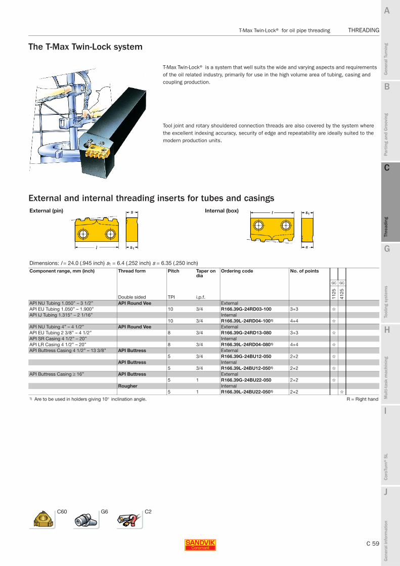
B
C 59
Gen
eral
Tur
ning
Par
ting
and
Gro
ovin
g
C
Thre
adin
g
G
Tool
ing
syst
ems
Mul
ti-ta
sk m
achi
ning
I
Cor
oTur
n® S
L
J
Gen
eral
info
rmat
ion
A
H
C
Thre
adin
g
T-Max Twin-Lock® for oil pipe threading THREADING
THREADING T-Max Twin-Lock® for oil pipe threading
The T-Max Twin-Lock system
External and internal threading inserts for tubes and casings
T-Max Twin-Lock® is a system that well suits the wide and varying aspects and requirements of the oil related industry, primarily for use in the high volume area of tubing, casing and coupling production.
Tool joint and rotary shouldered connection threads are also covered by the system where the excellent indexing accuracy, security of edge and repeatability are ideally suited to the modern production units.
External (pin) Internal (box)
Dimensions: l = 24.0 (.945 inch) s1 = 6.4 (.252 inch) s = 6.35 (.250 inch)Component range, mm (inch) Thread form Pitch Taper on
diaOrdering code No. of points
GC GC
Double sided TPI i.p.f. 1125
4125
API NU Tubing 1.050’’ – 3 1/2’’ API Round Vee ExternalAPI EU Tubing 1.050’’ – 1.900’’ 10 3/4 R166.39G-24RD03-100 3+3 ✩
API IJ Tubing 1.315’’ – 2 1/16’’ Internal10 3/4 R166.39L-24RD04-1001) 4+4 ✩
API NU Tubing 4’’ – 4 1/2’’ API Round Vee ExternalAPI EU Tubing 2 3/8’’ – 4 1/2’’ 8 3/4 R166.39G-24RD13-080 3+3 ✩
API SR Casing 4 1/2’’ – 20’’ InternalAPI LR Casing 4 1/2’’ – 20’’ 8 3/4 R166.39L-24RD04-0801) 4+4 ✩
API Buttress Casing 4 1/2’’ – 13 3/8’’ API Buttress External5 3/4 R166.39G-24BU12-050 2+2 ✩
API Buttress Internal5 3/4 R166.39L-24BU12-0501) 2+2 ✩
API Buttress Casing ≥ 16’’ API Buttress External5 1 R166.39G-24BU22-050 2+2 ✩
Rougher Internal5 1 R166.39L-24BU22-0501) 2+2 ✩
1) Are to be used in holders giving 10° inclination angle. R = Right hand
C60 G6 C2

C 60
THREADING T-Max Twin-Lock® for oil pipe threading
B
Gen
eral
Tur
ning
Par
ting
and
Gro
ovin
g
C
Thre
adin
g
G
Tool
ing
syst
ems
Mul
ti-ta
sk m
achi
ning
I
Cor
oTur
n® S
L
J
Gen
eral
info
rmat
ion
A
H
C
Thre
adin
g
THREADING T-Max Twin-Lock® for oil pipe threading
T-Max Twin-Lock®Lever design
Shank tool
T-Max Twin-Lock® SL cutting head
Main spare parts
Shank tool SL cutting headR166.39FG R 566.39KF
Pitch line
R166.39G/L
Pitch line
Right hand style shown
Pitch range Dimensions, mm, inch
Main application TPI Ordering code b f1 h h1 l110-5 R166.39FG-3232-24 32 38.6 32 32 148.4
1.260 1.520 1.260 1.260 5.842
R = Right hand
Pitch range Dimensions, mm, inch
Main application TPI Ordering code Coupling size dmm Dm min f1 l110-5 R566.39KF-404527-241) 40 40.00 60.30 25.80 44.20
1.575 2.374 1.016 1.740
1) Only for API Round Vee inserts, 8 and 10 TPI. R = Right hand
Lever Screw Key (mm) ShimR166.39FG 5432 005-01 174.3-820M 170.3-860 (2.5) 5321 110-02R566.39KF 5432 005-01 174.3-820M 170.3-860 (2.5) 5321 111-01
C59 C69 G6 C2 J2

B
C 61
Gen
eral
Tur
ning
Par
ting
and
Gro
ovin
g
C
Thre
adin
g
G
Tool
ing
syst
ems
Mul
ti-ta
sk m
achi
ning
I
Cor
oTur
n® S
L
J
Gen
eral
info
rmat
ion
A
H
C
Thre
adin
g
T-Max Twin-Lock® for oil pipe threading THREADING
THREADING T-Max Twin-Lock® for oil pipe threading
T-Max Twin-Lock®CartridgeLever design
Main spare parts
R 466.39KF
R166.39G/L
Right hand style shown
Pitch range Dimensions, mm, inch
Main application TPI Ordering code Dm min b f1 h h1 l110-5 R466.39KF-1832-24 114.00 25 30.0 24 18 80.0
4.488 .984 1.181 .945 .709 3.150
R = Right hand
Insert size
C Key (mm)Lever Screw Shim24 5432 005-01 174.3-820M 170.3-860 (2.5) 5321 110-01
C59 C69 C2 J2
Pitch line

C 62
THREADING T-Max Twin-Lock® for oil pipe threading
B
Gen
eral
Tur
ning
Par
ting
and
Gro
ovin
g
C
Thre
adin
g
G
Tool
ing
syst
ems
Mul
ti-ta
sk m
achi
ning
I
Cor
oTur
n® S
L
J
Gen
eral
info
rmat
ion
A
H
C
Thre
adin
g
THREADING T-Max Twin-Lock® for oil pipe threading
T-Max P cartridge for rough threading
Main spare parts
Lever design R 466.3KW
Right hand style shown
Insert size Pitch range Dimensions, mm, inch
Main application D iC mm TPI Ordering code Dm min f1 h h1 l1 l2 l816 3/8 0.5-3.0 32-6 R466.3KW-2030-16 79.00 29.7 26 20 59.3 67 29.36
3.110 1.170 1.024 .787 2.335 2.638 1.156
R = Right hand
Insert size
D Key (mm)Lever Screw Shim16 174.3-840M 174.3-820M 170.3-860 (2.5) 179.3-850M
A34 C69 C2 J2

B
C 63
Gen
eral
Tur
ning
Par
ting
and
Gro
ovin
g
C
Thre
adin
g
G
Tool
ing
syst
ems
Mul
ti-ta
sk m
achi
ning
I
Cor
oTur
n® S
L
J
Gen
eral
info
rmat
ion
A
H
C
Thre
adin
g
Spare parts THREADING
THREADING Spare parts
CoroThread® 266 externalShank tools/ Coromant Capto®
1 2 3 4
Shank tools Insert screw Key (Torx Plus)
Shims1)
Inclination angle +1°
Shim screwCoromant Capto® Right hand external Left hand external266R/LFG-1616-16 C3-266R/LFG-22040-16 5513 020-13 5680 049-05 (15IP/10IP) 5322 389-11 5322 390-11 5512 032-05266R/LFG-2020-16 C4-266R/LFG-27050-16 266R/LFG-2525-16 C5-266R/LFG-35060-16 266R/LFG-3225-16 C6-266R/LFG-45065-16 266R/LFGZ2525-16 C8-266R/LFG-55080-16266RFGZ3225-16 C4-266RFGZ27050-16 266R/LFG-123B C5-266RFGZ35060-16 266R/LFG-163D C6-266RFGZ45065-16266R/LFG-203D266R/LFGZ123B266R/LFGZ163D266RFGZ203D266R/LFA-1010-16-S266R/LFA-1212-16-S 266R/LFA-1616-16-S266R/LFA-063-S266R/LFA-083-S266R/LFA-103-S266R/LFA-123-SQS-266RFA-1010-16QS-266RFA-1212-16QS-266RFA-1616-16QS-266RFA-063QS-266RFA-083 QS-266RFA-103266R/LFG-164D C3-266R/LFG-22040-22 5513 020-26 5680 043-14 (20IP) 5322 379-11 5322 380-11 5512 032-04266R/LFG-204D C4-266R/LFG-27050-22266R/LFG-244E C5-266R/LFG-35060-22266R/LFGZ164D C6-266R/LFG-45065-22266R/LFGZ204D C8-266R/LFG-55080-22266R/LFG-2525-22 C4-266R/LFGZ27050-22266R/LFG-3232-22 C5-266R/LFGZ35060-22266R/LFG-4040-22 C6-266R/LFGZ45065-22266R/LFGZ2525-22266R/LFGZ3232-22266R/LFG-205D C6-266R/LFG-45065-27 5513 020-66 5680 043-15 (25IP) 5322 387-11 5322 388-11 5512 032-03266R/LFG-245E C6-266R/LFGZ45065-27266R/LFG-3232-27266R/LFG-4040-271) For optional shims, see page C45.
Nozzle for Coromant Capto® cutting units
Cutting unit size5
C3–C4 5691 034-01C5–C6 5691 034-02C8 5691 034-03
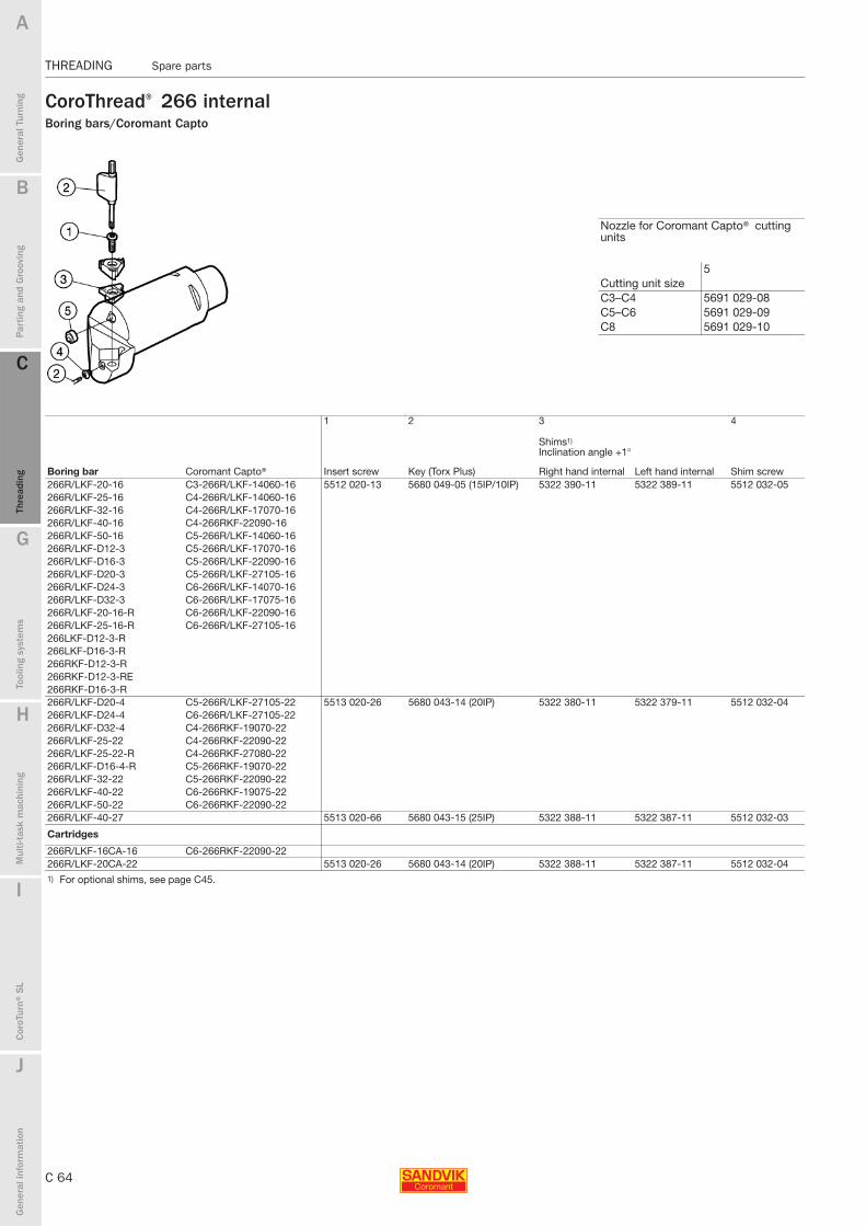
C 64
THREADING Spare parts
B
Gen
eral
Tur
ning
Par
ting
and
Gro
ovin
g
C
Thre
adin
g
G
Tool
ing
syst
ems
Mul
ti-ta
sk m
achi
ning
I
Cor
oTur
n® S
L
J
Gen
eral
info
rmat
ion
A
H
C
Thre
adin
g
THREADING Spare parts
CoroThread® 266 internalBoring bars/Coromant Capto
1 2 3 4
Boring bar Insert screw Key (Torx Plus)
Shims1)
Inclination angle +1°
Shim screwCoromant Capto® Right hand internal Left hand internal266R/LKF-20-16 C3-266R/LKF-14060-16 5512 020-13 5680 049-05 (15IP/10IP) 5322 390-11 5322 389-11 5512 032-05266R/LKF-25-16 C4-266R/LKF-14060-16266R/LKF-32-16 C4-266R/LKF-17070-16266R/LKF-40-16 C4-266RKF-22090-16266R/LKF-50-16 C5-266R/LKF-14060-16266R/LKF-D12-3 C5-266R/LKF-17070-16266R/LKF-D16-3 C5-266R/LKF-22090-16266R/LKF-D20-3 C5-266R/LKF-27105-16 266R/LKF-D24-3 C6-266R/LKF-14070-16 266R/LKF-D32-3 C6-266R/LKF-17075-16266R/LKF-20-16-R C6-266R/LKF-22090-16 266R/LKF-25-16-R C6-266R/LKF-27105-16266LKF-D12-3-R 266LKF-D16-3-R 266RKF-D12-3-R 266RKF-D12-3-RE 266RKF-D16-3-R266R/LKF-D20-4 C5-266R/LKF-27105-22 5513 020-26 5680 043-14 (20IP) 5322 380-11 5322 379-11 5512 032-04266R/LKF-D24-4 C6-266R/LKF-27105-22266R/LKF-D32-4 C4-266RKF-19070-22266R/LKF-25-22 C4-266RKF-22090-22266R/LKF-25-22-R C4-266RKF-27080-22266R/LKF-D16-4-R C5-266RKF-19070-22266R/LKF-32-22 C5-266RKF-22090-22266R/LKF-40-22 C6-266RKF-19075-22 266R/LKF-50-22 C6-266RKF-22090-22266R/LKF-40-27 5513 020-66 5680 043-15 (25IP) 5322 388-11 5322 387-11 5512 032-03
Cartridges
266R/LKF-16CA-16 C6-266RKF-22090-22266R/LKF-20CA-22 5513 020-26 5680 043-14 (20IP) 5322 388-11 5322 387-11 5512 032-041) For optional shims, see page C45.
Nozzle for Coromant Capto® cutting units
Cutting unit size5
C3–C4 5691 029-08C5–C6 5691 029-09C8 5691 029-10

B
C 65
Gen
eral
Tur
ning
Par
ting
and
Gro
ovin
g
C
Thre
adin
g
G
Tool
ing
syst
ems
Mul
ti-ta
sk m
achi
ning
I
Cor
oTur
n® S
L
J
Gen
eral
info
rmat
ion
A
H
C
Thre
adin
g
Spare parts THREADING
THREADING Spare parts
T-Max U-Lock® externalOBSOLETE TOOLS
Screw clamping
Quick Change-screw for insert sizes 16 (iC 3/8) and 22 (iC 1/2)
Quick Change-screw for insert sizes 16 (iC 3/8) and 22 (iC 1/2)
T-Max U screw for insert size 27 (iC 5/8)
1 2 3 2
Shank tools Coromant Capto® Insert screw (thread) Key (Torx Plus) Shim screw Key (Torx Plus)R/L166.4FG/FGZ-123B C3- R/L 166.4FG/FGZ22040-16 5513 026-01 (M4) 5680 051-03 (9IP) 5512 032-01 5680 051-03 (9IP)R/L166.4FG-163C C4- R/L 166.4FG/FGZ27050-16 5513 020-132) 5680 043-13 (15IP)3R/L166.4FG/FGZ-163D C5- R/L 166.4FG/FGZ35060-16R/L166.4FG/FGZ-203D C6- R/L 166.4FG/FGZ45065-16R/L166.4FG-1616-16 C8- R/L 166.4FG-55080-16R/L166.4FG-2020-16R/L166.4FG/FGZ-2525-16R/L166.4FG/FGZ-3225-16R/L166.4FA-1010-16-SR/L166.4FA-1212-16-SR/L166.4FA-1616-16-SR/L166.4FG-164D C3- R/L 166.4FG/FGZ22040-22 5513 026-02 (M5) 5680 049-02 (15IP) 5512 032-02 5680 049-02 (15IP)R/L166.4FG-204D C4- R/L 166.4FG/FGZ27050-22 5513 020-262) 5680 043-14 (20IP)3R/L166.4FG-244E C5- R/L 166.4FG/FGZ35060-22R/L166.4FGZ-2525-22 C6- R/L 166.4FG/FGZ45065-22R/L166.4FGZ-3232-22 C8- R/L 166.4FG-55080-22R/L166.4FG-4040-22R/L166.0FG-205D — 5513 020-14 (M6) 5680 043-15 (25IP)3 5512 090-08 −R/L166.0FG-245ER/L166.0FG-4040-27 — 5513 020-14 (M6) 5680 043-15 (25IP) 5512 090-08 −
4 5
Shank tools Coromant Capto® Key (size, mm)Shims1)
Inclination angle +1°R/L166.4FG/FGZ-123B C3- R/L 166.4FG/FGZ22040-16 − 5322 361-11R/L166.4FG-123B C4- R/L 166.4FG/FGZ27050-16R/L166.4FG/FGZ-163D C5- R/L 166.4FG/FGZ35060-16R/L166.4FG/FGZ-203D C6- R/L 166.4FG/FGZ45065-16R/L166.4FG-1616-16 C8- R/L 166.4FG-55080-16R/L166.4FG-2020-16R/L166.4FG/FGZ-2525-16R/L166.4FG/FGZ-3225-16R/L166.4FA-1010-16-SR/L166.4FA-1212-16-SR/L166.4FA-1616-16-SR/L166.4FG-164D C3- R/L 166.4FG/FGZ22040-22 − 5322 365-11R/L166.4FG-204D C4- R/L 166.4FG/FGZ27050-22R/L166.4FG-244E C5- R/L 166.4FG/FGZ35060-22R/L166.4FGZ-2525-22 C6- R/L 166.4FG/FGZ45065-22R/L166.4FGZ-3232-22 C8- R/L 166.4FG-55080-22R/L166.4FG-4040-22R/L166.0FG-205D — 3021010-060 (6.0) 5322 383-11R/L166.0FG-245ER/L166.0FG-4040-271) For optional shims, see page C57.2) U-screw for insert clamping, optional part delivered to separate
order3) Key for U-screw
Shank tools/ Coromant Capto®
Nozzle for Coromant Capto® cutting units
Cutting unit size6
C3–C4 5691 029-08C5–C6 5691 029-09C8 5691 029-10

C 66
THREADING Spare parts
B
Gen
eral
Tur
ning
Par
ting
and
Gro
ovin
g
C
Thre
adin
g
G
Tool
ing
syst
ems
Mul
ti-ta
sk m
achi
ning
I
Cor
oTur
n® S
L
J
Gen
eral
info
rmat
ion
A
H
C
Thre
adin
g
THREADING Spare parts
T-Max U-Lock® externalShank tools/ Coromant Capto®Wedge clamp design
To be used with CoroThread 266 inserts
1 2 3 4
Shims1)
Inclination angle +1°
Shank holder Coromant Capto® Wedge set Centre pin Key (Torx Plus) Right hand Left handR/L166.5FA-083 C3-R/L166.5FA/FAZ17039-16 5431 126-011 5313 033-01 5680 051-03 (9IP) 5322 371-11 5322 372-11R/L166.5FA-103 C3-R/L166.5FA/FAZ21055-16 R/L166.5FA-123B C3-R/L166.5FA/FAZ26065-16 R/L166.5FA-163D C3-R/L166.5FA/FAZ33075-16 R/L166.5FA-203DR/L166.5FA-1212-16R/L166.5FA-1616-16R/L166.5FA-2020-16R/L166.5FA-2525-16
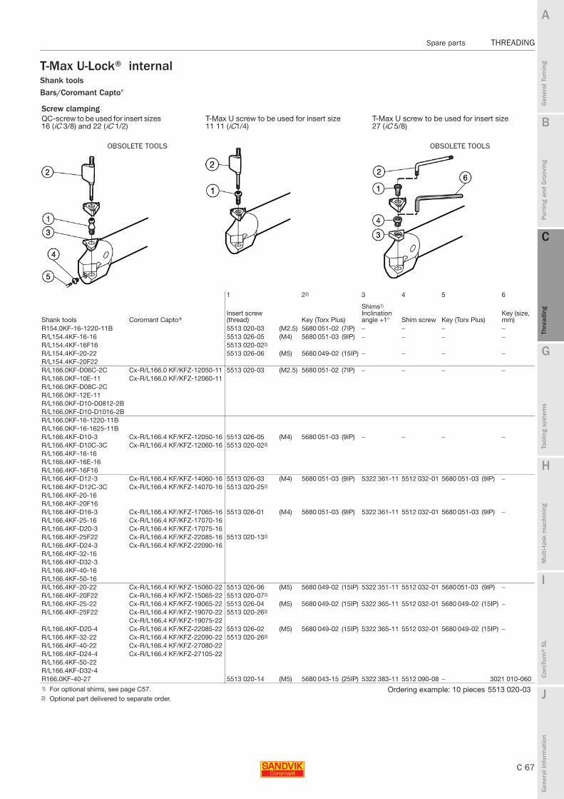
B
C 67
Gen
eral
Tur
ning
Par
ting
and
Gro
ovin
g
C
Thre
adin
g
G
Tool
ing
syst
ems
Mul
ti-ta
sk m
achi
ning
I
Cor
oTur
n® S
L
J
Gen
eral
info
rmat
ion
A
H
C
Thre
adin
g
Spare parts THREADING
THREADING Spare parts
T-Max U-Lock® internalShank toolsBars/Coromant Capto®
Screw clampingQC-screw to be used for insert sizes 16 (iC 3/8) and 22 (iC 1/2)
T-Max U screw to be used for insert size 11 11 (iC1/4)
T-Max U screw to be used for insert size 27 (iC 5/8)
1 22) 3 4 5 6
Shank tools Coromant Capto®Insert screw (thread) Key (Torx Plus)
Shims1)
Inclination angle +1° Shim screw Key (Torx Plus)
Key (size, mm)
R154.0KF-16-1220-11B 5513 020-03 (M2.5) 5680 051-02 (7IP) − − − −R/L154.4KF-16-16 5513 026-05 (M4) 5680 051-03 (9IP) − − − −R/L154.4KF-16F16 5513 020-022)
R/L154.4KF-20-22 5513 026-06 (M5) 5680 049-02 (15IP) − − − −R/L154.4KF-20F22R/L166.0KF-D06C-2C Cx-R/L166.0 KF/KFZ-12050-11 5513 020-03 (M2.5) 5680 051-02 (7IP) − − − −R/L166.0KF-10E-11 Cx-R/L166.0 KF/KFZ-12060-11R/L166.0KF-D08C-2CR/L166.0KF-12E-11R/L166.0KF-D10-D0812-2BR/L166.0KF-D10-D1016-2BR/L166.0KF-16-1220-11BR/L166.0KF-16-1625-11BR/L166.4KF-D10-3 Cx-R/L166.4 KF/KFZ-12050-16 5513 026-05 (M4) 5680 051-03 (9IP) − − − −R/L166.4KF-D10C-3C Cx-R/L166.4 KF/KFZ-12060-16 5513 020-022)
R/L166.4KF-16-16R/L166.4KF-16E-16R/L166.4KF-16F16R/L166.4KF-D12-3 Cx-R/L166.4 KF/KFZ-14060-16 5513 026-03 (M4) 5680 051-03 (9IP) 5322 361-11 5512 032-01 5680 051-03 (9IP) −R/L166.4KF-D12C-3C Cx-R/L166.4 KF/KFZ-14070-16 5513 020-252)
R/L166.4KF-20-16R/L166.4KF-20F16R/L166.4KF-D16-3 Cx-R/L166.4 KF/KFZ-17065-16 5513 026-01 (M4) 5680 051-03 (9IP) 5322 361-11 5512 032-01 5680 051-03 (9IP) −R/L166.4KF-25-16 Cx-R/L166.4 KF/KFZ-17070-16R/L166.4KF-D20-3 Cx-R/L166.4 KF/KFZ-17075-16R/L166.4KF-25F22 Cx-R/L166.4 KF/KFZ-22085-16 5513 020-132)
R/L166.4KF-D24-3 Cx-R/L166.4 KF/KFZ-22090-16R/L166.4KF-32-16R/L166.4KF-D32-3R/L166.4KF-40-16R/L166.4KF-50-16R/L166.4KF-20-22 Cx-R/L166.4 KF/KFZ-15060-22 5513 026-06 (M5) 5680 049-02 (15IP) 5322 351-11 5512 032-01 5680 051-03 (9IP) −R/L166.4KF-20F22 Cx-R/L166.4 KF/KFZ-15065-22 5513 020-072)
R/L166.4KF-25-22 Cx-R/L166.4 KF/KFZ-19065-22 5513 026-04 (M5) 5680 049-02 (15IP) 5322 365-11 5512 032-01 5680 049-02 (15IP) −R/L166.4KF-25F22 Cx-R/L166.4 KF/KFZ-19070-22 5513 020-262)
Cx-R/L166.4 KF/KFZ-19075-22R/L166.4KF-D20-4 Cx-R/L166.4 KF/KFZ-22085-22 5513 026-02 (M5) 5680 049-02 (15IP) 5322 365-11 5512 032-01 5680 049-02 (15IP) −R/L166.4KF-32-22 Cx-R/L166.4 KF/KFZ-22090-22 5513 020-262)
R/L166.4KF-40-22 Cx-R/L166.4 KF/KFZ-27080-22R/L166.4KF-D24-4 Cx-R/L166.4 KF/KFZ-27105-22R/L166.4KF-50-22R/L166.4KF-D32-4R166.0KF-40-27 5513 020-14 (M5) 5680 043-15 (25IP) 5322 383-11 5512 090-08 − 3021 010-0601) For optional shims, see page C57. Ordering example: 10 pieces 5513 020-032) Optional part delivered to separate order.
OBSOLETE TOOLS OBSOLETE TOOLS

C 68
THREADING Spare parts
B
Gen
eral
Tur
ning
Par
ting
and
Gro
ovin
g
C
Thre
adin
g
G
Tool
ing
syst
ems
Mul
ti-ta
sk m
achi
ning
I
Cor
oTur
n® S
L
J
Gen
eral
info
rmat
ion
A
H
C
Thre
adin
g
THREADING Spare parts
T-Max U-Lock®CartridgesScrew clamping
1 2 3 4 2
Cartridges Insert screw (thread) Key (size, Torx)
Shims1)
Inclination angle +1° Shim screw Key (Torx Plus)
R/L466.4KF-16CA-16 5513 026-01 (M4) 5680 051-03 (9IP) 5322 361-11 5512 032-01 5680 049-03 (9IP)5513 020-132)
R/L466.4KF-20CA-22 5513 026-02 (M5) 5680 049-02 (15IP) 5322 365-11 5512 032-02 5680 049-02 (15IP)5513 020-262)
7 8 9 10
CartridgesAdjusting screw, axial Mounting screw Washer Key (size, mm)
R/L466.4KF-16CA-16 438.3-828 434.9-830 3411 011-084 174.1-863 (2.5)
R/L466.4KF-20CA-22 438.3-839 434.9-827 3411 011-084 174.1-863 (2.5)
1) For optional shims, see page C57. Ordering example: 10 pieces 438.3-8282) Optional part delivered to separate order.
OBSOLETE TOOLS

B
C 69
Gen
eral
Tur
ning
Par
ting
and
Gro
ovin
g
C
Thre
adin
g
G
Tool
ing
syst
ems
Mul
ti-ta
sk m
achi
ning
I
Cor
oTur
n® S
L
J
Gen
eral
info
rmat
ion
A
H
C
Thre
adin
g
Spare parts THREADING
THREADING Spare parts
T-Max Twin-Lock®Holders for oil pipe threadingShank tools
Cartridges
T-Max P Cartridges
1 2 3 4 5 6
Shank tool Lever Screw Shim Shim pin Shim pin punch Key (mm)R166.39FG-3232-24 5432 005-01 174.3-820M 5321 110-02 174.3-860 174.3-870 170.3-860 (2.5)
Ordering example: 10 pieces 5432 005-01
1 2 3 4 5
Cartridge Lever Lever screw Key (mm) Shim Shim pinR466.39.KF-1832-24 5432 005-01 174.3-820M 170.3-860 (2.5) 5321 111-01 174.3-860
6 7 8 9 10
Shim pin punch
Adjusting screw, axial Mounting screw Washer Key (size, mm)
174.3-870 438.3-839 434.9-827 3411 011-084 174.1-863 (2.5)
Ordering example: 10 pieces 438.3-828
1 2 3 4 5
radiusT-Max P Cartridges Lever Lever screw Key (mm)
Shim (For insert thickness) Shim pinInch(mm)
R466.3KW-2030-16 174.3-840M 174.3-820M 170.3-860 (2.5) 179.3-850M (1.87) .016-.032 (0.4-0.8) 174.3-860179.3-858M (1.87)1) .047-.063 (1.2 - 1.6)1)
6 7 8 9 10
Shim pin punch
Adjusting screw, axial
Mounting screw Washer Key (size, mm)
R466.3KW-2030-16 174.3-870 434.9-839 434.9-830 3411 011-084 174.1-863 (2.5)
1) For optional shims, see page C57. Ordering example: 10 pieces 438.3-828

C 70
THREADING Infeed recommendations
B
Gen
eral
Tur
ning
Par
ting
and
Gro
ovin
g
C
Thre
adin
g
G
Tool
ing
syst
ems
Mul
ti-ta
sk m
achi
ning
I
Cor
oTur
n® S
L
J
Gen
eral
info
rmat
ion
A
H
C
Thre
adin
g
THREADING Infeed recommendations
ISO Metric (MM), external
ISO Metric (MM), internal
Dimensions x and z
mm inch
Pitch, mm
No. of infeeds
Total infeed
x
z
Radial infeed per pass
Total infeed = ap + 0.05 mm (.002 inch)
Pitch, mm
No. of infeeds Radial infeed per pass
Total infeed
x
z

B
C 71
Gen
eral
Tur
ning
Par
ting
and
Gro
ovin
g
C
Thre
adin
g
G
Tool
ing
syst
ems
Mul
ti-ta
sk m
achi
ning
I
Cor
oTur
n® S
L
J
Gen
eral
info
rmat
ion
A
H
C
Thre
adin
g
Infeed recommendations THREADING
THREADING Infeed recommendations
ISO inch (UN), external
ISO inch (UN), internal
Dimensions x and z
mm inch
Pitch, TPI
No. of infeeds
Total infeed
x
z
Radial infeed per pass
Total infeed = ap + 0.05 mm (.002 inch)
Pitch, TPI
No. of infeeds Radial infeed per pass
Total infeed
x
z

C 72
THREADING Infeed recommendations
B
Gen
eral
Tur
ning
Par
ting
and
Gro
ovin
g
C
Thre
adin
g
G
Tool
ing
syst
ems
Mul
ti-ta
sk m
achi
ning
I
Cor
oTur
n® S
L
J
Gen
eral
info
rmat
ion
A
H
C
Thre
adin
g
THREADING Infeed recommendations
Whitworth (WH), external and internal
BSPT (PT), external and internal
Dimensions x and z
mm inch
Pitch, TPI
No. of infeeds
Total infeed
External x
z
Internal x
z
Radial infeed per pass
Total infeed = ap + 0.05 mm (.002 inch)
Pitch, TPI
No. of infeeds Radial infeed per pass
Total infeed
External x
z
Internal x
z

B
C 73
Gen
eral
Tur
ning
Par
ting
and
Gro
ovin
g
C
Thre
adin
g
G
Tool
ing
syst
ems
Mul
ti-ta
sk m
achi
ning
I
Cor
oTur
n® S
L
J
Gen
eral
info
rmat
ion
A
H
C
Thre
adin
g
Infeed recommendations THREADING
THREADING Infeed recommendations
Round 30° Din405 (RN) external
Round 30° Din405 (RN) internal NPT (NT), external and internal
Dimensions x and z
mm inch
Pitch, TPI
No. of infeeds
Total infeed
x
z
Radial infeed per pass
Total infeed = ap + 0.05 mm (.002 inch)
Pitch, TPI
No. of infeeds Radial infeed per pass
Total infeed
Pitch, TPI
No. of infeeds
External x
z
Internal x
z
Radial infeed per pass
Total infeed
x
z

C 74
THREADING Infeed recommendations
B
Gen
eral
Tur
ning
Par
ting
and
Gro
ovin
g
C
Thre
adin
g
G
Tool
ing
syst
ems
Mul
ti-ta
sk m
achi
ning
I
Cor
oTur
n® S
L
J
Gen
eral
info
rmat
ion
A
H
C
Thre
adin
g
THREADING Infeed recommendations
ACME (AC), external
ACME (AC), internal
Dimensions x and z
mm inch
Pitch, TPI
No. of infeeds
Total infeed
x
z
Radial infeed per pass
Total infeed = ap + 0.05 mm (.002 inch)
Pitch, TPI
No. of infeeds Radial infeed per pass
x
z
Total infeed

B
C 75
Gen
eral
Tur
ning
Par
ting
and
Gro
ovin
g
C
Thre
adin
g
G
Tool
ing
syst
ems
Mul
ti-ta
sk m
achi
ning
I
Cor
oTur
n® S
L
J
Gen
eral
info
rmat
ion
A
H
C
Thre
adin
g
Infeed recommendations THREADING
THREADING Infeed recommendations
Stub-ACME (SA), external and internalDimensions x and z
mm inch
Pitch, TPI
No. of infeeds
Total infeed
External x
z
Internal x
z
Radial infeed per pass
Total infeed = ap + 0.05 mm (.002 inch)

C 76
THREADING Infeed recommendations
B
Gen
eral
Tur
ning
Par
ting
and
Gro
ovin
g
C
Thre
adin
g
G
Tool
ing
syst
ems
Mul
ti-ta
sk m
achi
ning
I
Cor
oTur
n® S
L
J
Gen
eral
info
rmat
ion
A
H
C
Thre
adin
g
THREADING Infeed recommendations
Trapezoidal (TR), external and internalDimensions x and z
mm inch
Pitch, mm
No. of infeeds
Total infeed
External x
z
Internal x
z
Radial infeed per pass
Total infeed = ap + 0.05 mm (.002 inch)

B
C 77
Gen
eral
Tur
ning
Par
ting
and
Gro
ovin
g
C
Thre
adin
g
G
Tool
ing
syst
ems
Mul
ti-ta
sk m
achi
ning
I
Cor
oTur
n® S
L
J
Gen
eral
info
rmat
ion
A
H
C
Thre
adin
g
Infeed recommendations THREADING
THREADING Infeed recommendations
UNJ, external
NPTF (NT), external and internal MJ, external
Dimensions x and z
mm inch
Pitch, TPI
No. of infeeds
Total infeed
x
z
Radial infeed per pass
Total infeed = ap + 0.05 mm (.002 inch)
Pitch, TPI
No. of infeeds Radial infeed per pass
Total infeed
Pitch, mm
No. of infeeds
External x
z
Internal x
zRadial infeed per pass
Total infeed
x
z

C 78
THREADING Infeed recommendations
B
Gen
eral
Tur
ning
Par
ting
and
Gro
ovin
g
C
Thre
adin
g
G
Tool
ing
syst
ems
Mul
ti-ta
sk m
achi
ning
I
Cor
oTur
n® S
L
J
Gen
eral
info
rmat
ion
A
H
C
Thre
adin
g
THREADING Infeed recommendations
API thread forms
Dimensions x and z
mm inch
No. of infeeds
InsertPitch, TPI x z
Total infeedRadial infeed per pass
Total infeed = ap + 0.05 mm (.002 inch)
API 60° V-0.038R
API 60° V-0.040
API 60° V-0.050
API Round 60°
API Buttress

B
C 79
Gen
eral
Tur
ning
Par
ting
and
Gro
ovin
g
C
Thre
adin
g
G
Tool
ing
syst
ems
Mul
ti-ta
sk m
achi
ning
I
Cor
oTur
n® S
L
J
Gen
eral
info
rmat
ion
A
H
C
Thre
adin
g
Infeed recommendations THREADING
THREADING Infeed recommendations
Multi-pointDimensions x and z
mm inch
ISO Metric (MM) ISO inch (UN), external Whitworth (WH) NPT (NT)
Pitch, mm Pitch, TPI Pitch, TPIPitch, TPI
x
z
External
No. of infeeds Radial infeed per pass
Total infeed
Internal
Pitch, mm Pitch, TPI Pitch, TPIPitch, TPI
x
z
No. of infeeds Radial infeed per pass
Total infeed
Total infeed = ap + 0.05 mm (.002 inch)

C 80
THREADING Infeed recommendations
B
Gen
eral
Tur
ning
Par
ting
and
Gro
ovin
g
C
Thre
adin
g
G
Tool
ing
syst
ems
Mul
ti-ta
sk m
achi
ning
I
Cor
oTur
n® S
L
J
Gen
eral
info
rmat
ion
A
H
C
Thre
adin
g
THREADING Infeed recommendations
Infeed recommendations
The type of infeed, number of passes and size of infeed can have a decisive impact on the threading operation. The infeed recommendations are intended as starting values. Suitable number of passes must be determined by trial and error. The harder the workpiece the more number of passes.- The workpiece diameter should not be more than .006 inch (0.14 mm)
larger than the max diameter of the thread to achieve optimum tool life.
- Infeeds of less than .002 inch (0.05 mm) should be avoided, for austenitic stainless steels not less than .003 inch (0.08 mm).
- When using grade CB20 the max infeed value should be .003 inch (0.07 mm).
- For C-geometry inserts, spring pass (a pass without infeed) should not be used.
- For Multi-point inserts it is essential that the recommendations on page C79 are used.
- For V-profile inserts the recommended number of passes that is used for full form inserts can be used.
Cutting speed Starting cutting speed recommendations are given on page C82. Careful observation on the cutting edge can help you to achieve the best possible threading results.- A cutting speed that is too low can result in built-up edge- A cutting speed that is too high can result in plastic deformation of the
edge
FormulaFormula to calculate infeed for each pass in a reduced series.
Δap Radial infeedx Actual pass (in a series from 1 to nap)ap Total depth of thread. See page C70nap Number of infeeds. See page C70φ 1st pass = 0.3
2nd pass = 13rd and higher passes = x–1
Radial infeed Modified flank infeed Incremental infeed Modified flank infeed 1°
F-geometry
A-geometry
C-geometry
vc m/minft/min
For technical information see our Metal Cutting Technical guide

Turning_Utfyllnadssidor.indd 4 2010-12-09 12:31:01

C 82
THREADING Cutting data
B
Gen
eral
Tur
ning
Par
ting
and
Gro
ovin
g
C
Thre
adin
g
G
Tool
ing
syst
ems
Mul
ti-ta
sk m
achi
ning
I
Cor
oTur
n® S
L
J
Gen
eral
info
rmat
ion
A
H
C
Thre
adin
g
THREADING Cutting data
Cutting speed recommendations, metric valuesNote: Most cutting speeds are recommended for a tool life of 15 minutes. To increase lifetime, see information in Metalcutting Technical Guide.ISO P
CMC No. Material
Hardness GradesGC1125 GC1135 GC1020 H13A
MC No. HB Cutting speed (vc), m/min Unalloyed steel
P1.1.Z.AN 01.1 C = 0.1–0.25% 125 230 205 185 160P1.2.Z.AN 01.2 C = 0.25–0.55% 150 195 170 155 130P1.3.Z.AN 01.3 C = 0.55–0.80% 170 180 160 145 125
Low-alloy steel(alloying elements ≤5%)
P2.1.Z.AN 02.1 Non-hardened 180 155 140 125 115P2.1.Z.AN 02.12 Ball bearing steel 210 145 125 115 105P2.5.Z.HT 02.2 Hardened and tempered 275 120 105 95 80P2.5.Z.HT 02.2 Hardened and tempered 350 95 85 75 65
High-alloy steel(alloying elements >5%)
P3.0.Z.AN 03.11 Annealed 200 140 120 110 105P3.0.Z.HT 03.21 Hardened tool steel 325 115 100 80 70
Steel castingsP1.5.C.UT 06.1 Unalloyed 180 220 200 180 170P2.6.C.UT 06.2 Low-alloy (alloying elements ≤5%) 200 150 130 120 95P3.0.C.UT 06.3 High-alloy (alloying elements >5%) 225 120 105 95 85P3.2.C.AQ 06.33 Manganese steel, 12–14% Mn 250 40 38 35 33
ISO MBars/forgedFerritic/martensitic
P5.0.Z.AN 05.11 Non-hardened 200 160 145 130 90P5.0.Z.PH 05.12 PH-hardened 330 115 100 90 70P5.0.Z.HT 05.13 Hardened 330 105 95 85 65
Bars/forgedAustenitic
M1.0.Z.AQ 05.21 Austenitic 180 140 130 120 75M1.0.Z.PH 05.22 PH-hardened 330 100 90 80 60M2.0.Z.AQ 05.23 Super austenitic 200 80 75 70 50
Stainless steel – Bars/forgedAustenitic-ferritic (Duplex)
M3.1.Z.AQ 05.51 Non-weldable C ≥ 0,05% Weldable C < 0,05% 230 110 100 90 -M3.2.Z.AQ 05.52 Weldable < 0.05%C 260 90 80 70 -
Stainless steel – CastFerritic/martensitic
P5.0.C.UT 15.11 Non-hardened 200 120 100 90 9015.12 PH-hardened 330 90 80 70 55
P5.0.C.HT 15.13 Hardened 330 70 65 60 50Stainless steel – CastAustenitic
M1.0.C.UT 15.21 Austenitic 180 120 110 100 8015.22 PH-hardened 330 70 65 60 50
M2.0.C.AQ 15.23 200 90 80 70 40Stainless steel – CastAustenitic-ferritic (Duplex)
M3.1.C.AQ 15.51 Non-weldable ≥ 0.05%C 230 100 95 85 -M3.2.C.AQ 15.52 Weldable < 0.05%C 260 75 70 65 -
ISO KMalleable cast iron
07.1 Ferritic (short chipping) 130 170 150 135 95K1.1.C.NS 07.2 Pearlitic (long chipping) 230 125 110 100 70
Grey cast ironK2.1.C.UT 08.1 Low tensile strength 180 160 140 130 85K2.2.C.UT 08.2 High tensile strength 220 140 130 120 80
Nodular SG ironK3.1.C.UT 09.1 Ferritic 160 140 135 125 110K3.3.C.UT 09.2 Pearlitic 250 110 100 90 80K3.4.C.UT 09.3 Martensitic 380 80 75 65 60
ISO NAluminium alloys Wrought/wrought and
N1.2.Z.UT 30.11 + cold-worked, non aging Aged
60 500 500 500 500N1.2.Z.AG 30.12 100 500 500 500 450
Aluminium alloys N1.3.C.UT 30.21 Cast, non-aging 75 500 500 455 425N1.3.C.AG 30.22 Cast or cast and aged 90 400 325 280 250
Aluminium alloys 30.41 Cast Si 13-15%
Cast Si 16-22%130 300 270 245 210
N1.4.C.NS 30.42 130 300 270 245 210Copper and copper alloys
N3.3.U.UT 33.1 Free cutting alloys, ≥1% Pb 110 500 460 420 370N3.2.C.UT 33.2 Brass, leaded bronzes, ≤1% Pb 90 300 270 245 210N3.1.U.UT 33.3 Bronze and non-leadad copper incl. electrolytic copper 100 210 190 175 150

B
C 83
Gen
eral
Tur
ning
Par
ting
and
Gro
ovin
g
C
Thre
adin
g
G
Tool
ing
syst
ems
Mul
ti-ta
sk m
achi
ning
I
Cor
oTur
n® S
L
J
Gen
eral
info
rmat
ion
A
H
C
Thre
adin
g
Cutting data THREADING
THREADING Cutting data
Cutting speed recommendations, metric valuesNote: Most cutting speeds are recommended for a tool life of 15 minutes. To increase lifetime, see information in Metalcutting Technical Guide.ISO S
CMC No. Material
Hardness Brinell
Grades
GC1125 GC1135 GC1020 H13A CB7015MC No. HB Cutting speed (vc), m/min
Heat resistant alloysIron base
S1.0.U.AN 20.11 Annealed Aged
200 55 50 45 45 -S1.0.U.AG 20.12 280 35 35 30 30 -
Nickel baseS2.0.Z.AN 20.21 Annealed
Aged250 25 25 20 19 -
S2.0.Z.AG 20.22 350 15 15 13 13 -S2.0.C.NS 20.24 Cast 320 13 13 10 11 -
Cobalt baseS3.0.Z.AN 20.31 Annealed Aged 200 30 30 25 22 -S3.0.Z.AG 20.32 300 20 18 15 14 -S3.0.C.NS 20.33 Cast 320 20 18 15 15 -
Titanium alloysS4.1.Z.UT 23.1 Commercial pure (99.5% Ti) 400 Rm 170 160 140 120 -S4.2.Z.AN 23.21 α, near α and α + β alloys, annealed
α + β alloys in aged conditions, β alloys, annealed or aged950 Rm 70 65 60 50 -
S4.3.Z.AG 23.22 1050 Rm 60 55 50 40 -
ISO HExtra hard steel
H1.1.Z.HA 04.1 Hardened and tempered 47 HRC 60 50 50 - 130H1.3.Z.HA 04.1 60 HRC 39 32 32 - 130
Chilled cast ironH2.0.C.UT 10.1 Cast or cast and aged 400 45 40 35 50 -
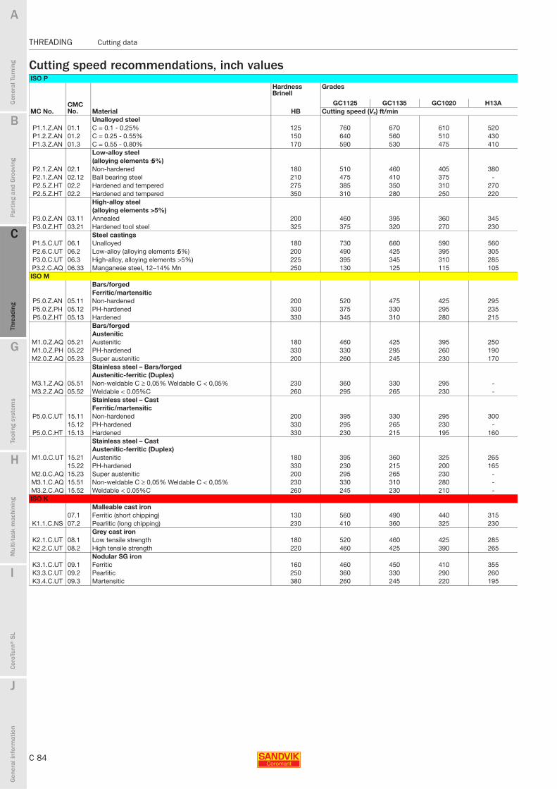
C 84
THREADING Cutting data
B
Gen
eral
Tur
ning
Par
ting
and
Gro
ovin
g
C
Thre
adin
g
G
Tool
ing
syst
ems
Mul
ti-ta
sk m
achi
ning
I
Cor
oTur
n® S
L
J
Gen
eral
info
rmat
ion
A
H
C
Thre
adin
g
THREADING Cutting data
Cutting speed recommendations, inch valuesISO P
Hardness Brinell
Grades
CMC No.
GC1125 GC1135 GC1020 H13AMC No. Material HB Cutting speed (Vc) ft/min
Unalloyed steelP1.1.Z.AN 01.1 C = 0.1 - 0.25% 125 760 670 610 520P1.2.Z.AN 01.2 C = 0.25 - 0.55% 150 640 560 510 430P1.3.Z.AN 01.3 C = 0.55 - 0.80% 170 590 530 475 410
Low-alloy steel(alloying elements ≤5%)
P2.1.Z.AN 02.1 Non-hardened 180 510 460 405 380P2.1.Z.AN 02.12 Ball bearing steel 210 475 410 375 -P2.5.Z.HT 02.2 Hardened and tempered 275 385 350 310 270P2.5.Z.HT 02.2 Hardened and tempered 350 310 280 250 220
High-alloy steel(alloying elements >5%)
P3.0.Z.AN 03.11 Annealed 200 460 395 360 345P3.0.Z.HT 03.21 Hardened tool steel 325 375 320 270 230
Steel castingsP1.5.C.UT 06.1 Unalloyed 180 730 660 590 560P2.6.C.UT 06.2 Low-alloy (alloying elements ≤5%) 200 490 425 395 305P3.0.C.UT 06.3 High-alloy, alloying elements >5%) 225 395 345 310 285P3.2.C.AQ 06.33 Manganese steel, 12–14% Mn 250 130 125 115 105ISO M
Bars/forgedFerritic/martensitic
P5.0.Z.AN 05.11 Non-hardened 200 520 475 425 295P5.0.Z.PH 05.12 PH-hardened 330 375 330 295 235P5.0.Z.HT 05.13 Hardened 330 345 310 280 215
Bars/forgedAustenitic
M1.0.Z.AQ 05.21 Austenitic 180 460 425 395 250M1.0.Z.PH 05.22 PH-hardened 330 330 295 260 190M2.0.Z.AQ 05.23 Super austenitic 200 260 245 230 170
Stainless steel – Bars/forgedAustenitic-ferritic (Duplex)
M3.1.Z.AQ 05.51 Non-weldable C ≥ 0,05% Weldable C < 0,05% 230 360 330 295 -M3.2.Z.AQ 05.52 Weldable < 0.05%C 260 295 265 230 -
Stainless steel – CastFerritic/martensitic
P5.0.C.UT 15.11 Non-hardened 200 395 330 295 30015.12 PH-hardened 330 295 265 230 -
P5.0.C.HT 15.13 Hardened 330 230 215 195 160Stainless steel – CastAustenitic-ferritic (Duplex)
M1.0.C.UT 15.21 Austenitic 180 395 360 325 26515.22 PH-hardened 330 230 215 200 165
M2.0.C.AQ 15.23 Super austenitic 200 295 265 230 -M3.1.C.AQ 15.51 Non-weldable C ≥ 0,05% Weldable C < 0,05% 230 330 310 280 -M3.2.C.AQ 15.52 Weldable < 0.05%C 260 245 230 210 -ISO K
Malleable cast iron07.1 Ferritic (short chipping) 130 560 490 440 315
K1.1.C.NS 07.2 Pearlitic (long chipping) 230 410 360 325 230Grey cast iron
K2.1.C.UT 08.1 Low tensile strength 180 520 460 425 285K2.2.C.UT 08.2 High tensile strength 220 460 425 390 265
Nodular SG ironK3.1.C.UT 09.1 Ferritic 160 460 450 410 355K3.3.C.UT 09.2 Pearlitic 250 360 330 290 260K3.4.C.UT 09.3 Martensitic 380 260 245 220 195

B
C 85
Gen
eral
Tur
ning
Par
ting
and
Gro
ovin
g
C
Thre
adin
g
G
Tool
ing
syst
ems
Mul
ti-ta
sk m
achi
ning
I
Cor
oTur
n® S
L
J
Gen
eral
info
rmat
ion
A
H
C
Thre
adin
g
Cutting data THREADING
THREADING Cutting data
THREADING Cutting data
Cutting speed recommendations, inch valuesISO N
Hardness Brinell
Grades
MC No.CMC No.
GC1125 GC1135 GC1020 H13A CB7015Material HB Cutting speed (Vc) ft/minAluminium alloys Wrought/wrought and
N1.2.Z.UT 30.11 + cold-worked, non aging Aged
60 1650 1650 1650 1650N1.2.Z.AG 30.12 100 1650 1650 1650 1450
Aluminium alloys N1.3.C.UT 30.21 Cast, non-aging 75 1650 1650 1500 1400N1.3.C.AG 30.22 Cast or cast and aged 90 1300 1050 920 820
Aluminium alloys 30.41 Cast Si 13-15% 130 980 890 800 690
N1.4.C.NS 30.42 Cast Si 16-22% 130 980 890 800 690Copper and copper alloys
N3.3.U.UT 33.1 Free cutting alloys, ≥1% Pb 110 1650 1500 1400 1200N3.2.C.UT 33.2 Brass, leaded bronzes, ≤1% Pb 90 980 890 800 690N3.1.U.UT 33.3 Bronze and non-leadad copper incl. electrolytic copper 100 690 620 570 490
ISO SHeat resistant super alloysIron base
S1.0.U.AN 20.11 Annealed or solution treated 200 180 165 145 145S1.0.U.AG 20.12 Aged or solution treated and aged 280 115 115 100 100
Nickel baseS2.0.Z.AN 20.21 Annealed or solution treated 250 80 80 65 60S2.0.Z.AG 20.22 Aged or solution treated and aged 350 50 50 45 45
S2.0.C.NS 20.24 Cast or cast and aged 320 45 45 33 35Cobalt base
S3.0.Z.AN 20.31 Annealed or solution treated 200 100 100 80 70S3.0.Z.AG 20.32 Solution treated and aged 300 65 60 50 45S3.0.C.NS 20.33 Cast or cast and aged 320 65 60 50 50
Titanium alloysS4.1.Z.UT 23.1 Commercial pure (99,5% Ti) 400 Rm 560 520 460 395S4.2.Z.AN 23.21 α, near α and α + β alloys, annealed 950 Rm 230 215 195 -S4.3.Z.AG 23.22 α, near α and α+β alloys, annealed α+β alloys in aged cond, β
alloys, annealed or aged1050 Rm 195 180 165 -
ISO HExtra hard steel
H1.1.Z.HA 04.1 Hardened and tempered 47 HRC 200 165 165 - 420H1.3.Z.HA 04.1 Hardened and tempered 60 HRC 125 105 105 - 420
Chilled cast ironH2.0.C.UT 10.1 Cast or cast and aged 400 150 130 115 170 -
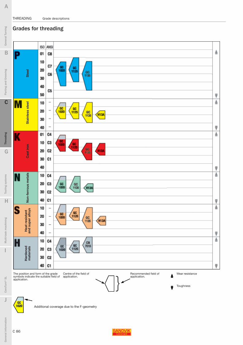
C 86
THREADING Grade descriptions
B
Gen
eral
Tur
ning
Par
ting
and
Gro
ovin
g
C
Thre
adin
g
G
Tool
ing
syst
ems
Mul
ti-ta
sk m
achi
ning
I
Cor
oTur
n® S
L
J
Gen
eral
info
rmat
ion
A
H
C
Thre
adin
g
THREADING Grade descriptions
Grades for threading
The position and form of the grade symbols indicate the suitable field of application.
Centre of the field of application.
Recommended field of application.
Wear resistance
Toughness
Additional coverage due to the F-geometry
Ste
elS
tain
less
ste
el
Cas
t ir
on
No
n-fe
rro
us m
etal
sH
eat
resi
stan
t an
d s
uper
allo
ysH
ard
ened
m
ater
ials

B
C 87
Gen
eral
Tur
ning
Par
ting
and
Gro
ovin
g
C
Thre
adin
g
G
Tool
ing
syst
ems
Mul
ti-ta
sk m
achi
ning
I
Cor
oTur
n® S
L
J
Gen
eral
info
rmat
ion
A
H
C
Thre
adin
g
Grade descriptions THREADING
THREADING Grade descriptions
Grades for threading
GC1020 (HC) – P20 (P10-P40)Good all round PVD-coated grade for threading steels. Combines good wear resistance with edge sharpness also in low carbon.GC4125 (HC) – P20 (P05 P35)Used as an optimizing PVD-coated grade for varius steel threadings. It has excellent wear resistance at high cutting speeds and long cutting times.GC1125 (HC) - P20 (P05-P35)PVD-coated grade with very good wear resistance for varius steel threadings. To be used at high cutting speeds and long cutting times.
GC1020 (HC) – M20 (M10-M30) Good all round PVD-coated grade for threading stainless steels. Combines good wear resistance with edge sharpness.GC4125 (HC) – M20 (M05-M25) This PVD-coated grade works well in stainless steels and other smearing materials at higher cutting speed.GC1125 (HC) – M20 (M10-M30)PVD-coated grade for stainless steels and other smearing materials at higher cutting speed.H13A (HW) – M25 (M20-M30) Uncoated carbide grade. Combines good abrasive wear resistance and toughness. For moderate to low speeds.
GC1020 (HC) – K15 (K01-K20) Good PVD-coated all round grade for threading cast iron. Combines good wear resistance with edge sharpness. Moderate cutting speeds.GC4125 (HC) – K15 (K05-K20) This PVD-allround grade for toughness demanding operations. To be used at higher cutting speeds.GC1125 (HC) – K15 (K05-K20PVD-coated grade with very good wear resistance in short chipping materials. To be used at high cutting speeds.H13A (HW) – K20 (K10-K25) Uncoated carbide grade. Combines good abrasive wear resistance and toughness. For moderate to low speeds.
Steel, cast steel, long chipping malleable iron
Austenitic/ferritic/martensitic stainless steel, cast steel, manganese steel, alloy cast iron, malleable iron, free cutting steel.
Cast iron, chilled cast iron, short chipping malleable iron.
GC1020 (HC) – N25 (N10-N30)Good all round PVD-coated grade with good wear resistance and edge sharpness in non-ferrous materials.H13A (HW) – N25 (N20-N30)Uncoated carbide grade. Combines good abrasive wear resistance and toughness for medium to rough turning of aluminum alloys and brass.
GC1020 (HC) – S20 (S05-S30)A PVD-coated carbide grade for toughness demanding super alloy operations.To be used at low cutting speeds.GC4125 (HC) – S20 (S10-S25)A PVD-coated carbide grade for toughness demanding super alloy operations. To be used at lower cutting speeds.GC1125 (HC) – S20 (S10-S25)PVD-coated carbide grade for toughness demanding super alloy operations. To be used at lower cutting speeds.H13A (HW) – S25 (S20-S30)Uncoated carbide grade. Combines good abrasive wear resistance and toughness for threading of heat resistant alloys and titanium alloys.
GC1020 (HC) – H20 (H05-H30)Good all round PVD-coated grade with good wear resistance and edge sharpness. To be used at low cutting speed.GC4125 (HC) – H20 (H10 − H25)A PVD-coated carbide grade. As an all round grade to be used with lower cutting speeds.GC1125 (HC) – H20 (H10-H25)PVD-coated carbide grade. To be used with lower cutting speeds.CB20 (BN) – H10 (H01−H20)High performance composite material consisting of cubic Boron nitride (CBN). Suitable for hardened ferrous materials and cast-iron.
Non ferrous metals
Heat resistant and super alloys
Hardened materials
Letter symbols specifying the designation of hard cutting materials:
Hardmetals: HW Uncoated hardmetal containing primarily
tungsten carbide (WC)
HT Uncoated hardmetal, also called cermet, containing primarily titanium carbides (TIC) or titanium nitrides (TIN) or both.
HC Hardmetals as above, but coated
Ceramics:CA Oxide ceramics containing primarily
aluminium oxide (Al2O3).
CM Mixed ceramics containing primarily aluminium oxide (Al2O3) but containing components other than oxides.
CN Nitride ceramics containing primarily silicon nitride (Si3N4).
CC Ceramics as above, but coated.
Boron nitride:BN Cubic boron nitride
Note: Cubic boron nitride is also named superhard cutting material.