how to...& hardy classics, children's cartoons. in offering these enter - ment cartridge to...
TRANSCRIPT

. OM
r Oc Nou.19s9
-
6_
a - ®
GERNSBACK_ PUBLICAT10
How To
Fix Bad Color
FOR MODEL RR
Electronic
TI:t ttle rimenters
N Build R -E's
One -IC Radio
E: E ,
www.americanradiohistory.com

Dazzle your friends with lightworks.
Sound n' Color The now dimension to music pleasure. EICO All Electronic Solid -State Audio -Color Organs transform sound waves into moving synchronized color images. Connect easily to speaker leads of hi -fi or radio. From $29.95.
Translators The electronics you need to create audio - stimulated light displays to your own imagination. Actuates: Light Display Units, Strobe Lites, any lamp configuration (Xmas trees, patio lights, etc.). From $24.95 kit, $39.95 wired.
Strobe Lites High- intensity bursts of white light from Xenon tube flash in cadence with each beat of audio. From $24.95 kit, $39.95 wired.
Build the Stereo bits praised by experts. ri All amplifier power ratings according to IHF standards. Cortina designed and manufactured in S.A. and guaranteed by EICO.
r e" r ili r
70 -Watt AM /FM Stereo Receiver including cabinet. Cortina 3770, $189.95 kit, $279.95 wired. 70 -Watt FM Stereo Receiver including cabinet. Cortina 3570, $169.95 kit, $259.95 wired.
Fig° trot
EC -1100 FM WIRELESS MIKE $9.95
.41111111111. - .. . .. ..
-err 150 -Watt Silicon Solid -State Stereo Amplifier, including cabinet. For the audio perfectionist. Cortina 3150, $149.95 kit, $225 wired. 70 -Watt Silicon Solid -State Stereo Amplifier, including cabinet. Cortina 3070, $99.95 kit, $139.95 wired,
10111111111111...
FM Stereo Tuner including cabinet. Cortina 3200, $99.95 kit, $139.95 wired.
Build for fun and use with Eicocraft' jiffy project kits.
The newest excitement in kits. pCCRAFT4re 100% solid -state and professional. Expandable, interconnectable. Excellent =In 5995
as introductions to electronics. No technical experience needed. Finest parts, pre -drilled etched printed circuit boards, step -by -step instructions. 36 kits to select from, $2.50 to $9.95. Just released: EC -2600 "Super Snoop" $8.95; EC -2700 Police & Fire Converter
(lo band) $7.95; EC -2800 Aircraft Converter $7.95; EC -2900 Police & Fire Converter (hi band) $7.95; EC -3100 2- Station Intercom (with cases) $10.95; EC -3200 "Do -It- Yourself" PC Etching Kit $4.95; EC -2300 Audio Preamplifier $8.95; EC -2400 Bullhorn 58.95; EC -2500 Fuzzbox $8.95.
Shape up your own car /boat with EICO Engine Analyzer For all 6V/12V systems; 4, 6, 8 -cyl. engines. Completely tests your total ignition /electrical Now you can keep your car or boat engine system. Complete with comprehensive Tune -up & In tip -top shape with this solid- state, portable, Trouble- shooting Manual. FICO 888, $49.95 kit, self -powered universal engine analyzer. $69.95 wired.
EC -1900 TREASURE FINDER $9.95
Be a technocrat with EICO ®solid -state test equipment Only EICO brings you laboratory precision and long life at lowest cost.
EICO 240 Solid -State FICO 379 Solid -State FICO 242 Solid -State FICO 150 Solid -State FET -TVOM Sine /Square Wave Generator Deluxe FET -TVOM Signal Tracer $49.95 kit, $69.95 wired $54.95 kit, $74 95 wired $59.95 kit, $79.95 wired. $49.95 kit, $69.95 wired
FICO 330 Solid -State RF Signal Generator $59.95 kit, $79.95 wired
You save up to 50% with EICO Kits. Since 1945, Best Buys in Electronics. Over 3 Million EICO Instruments Now in Use.
Send me FREE catalog describing the FREE 1969 CATALOG full EICO line of 200 best buys, and name
of nearest dealer.
Electronic Instrument Co., Inc. 283 Malta Street, Brooklyn, N.Y. 11207
Available In Canada
EI-11
Name
Address
City State Zip
www.americanradiohistory.com

Dialtronic Automatic Telephone Communicator Model DT -1000
Radar Sentry Alarm announces a new powerful way to stop crime ... "Dialtronic" Radar Sentry Alarm announces a new powerful way to fight crime. Imagine a security system that automatically and silently delivers any emergency message for which it is programmed. Dialtronic adds a new dimension to your security needs. Advanced concepts in tech- nology and design bring you a new level of security. Providing un- limited application, the Dialtronic uses solid state circuitry to bring help immediately. Use it with existing alarm systems or any other sensing device. Dialtronic is the ideal personal protection for any- one who is vulnerable to intruders. Dialtronic will perform with never a lapse in security . . . You are assured of highly reliable pro- tection.
The Crimebusters Want You! ... Now!
Also used to protect premises while they are being occupied, the Radar Dialtronic gives push button pro- tection to businesses and home owners alike. This system is trig- gered by a hidden push button or portable transmitter. Once set into action, it automatically dials the phone -delivering any pre- recorded message for which it is programmed without the would - be-thiefs' knowledge. In effect, the Dialtronic gives you a direct line to police, fire departments, in -plant security, key personnel ... whoever you designate. Dialtronic's built -in programmer lets you magnetically store "error free" messages on cassette type tape cartridges. Stored informa- tion is instantly available to notify proper officials, delivering correct message in each case.
E> . . . To make the biggest profits of your career - filling ready -made demand for the dramatic new RADAR SENTRY ALARM systems. Get started NOW as dealer or distributor -step into five - figure income at once, with unlimited potential and wide -open opportunity to grow as you gol MAIL COUPON AT ONCE!
' Circle 8 on reader service card
Advantages of Dialtronic Telephone Communicator
Eliminates costly leased tele- phone lines. Simultaneously stores up to ten separate messages on magnetic tape. Automatically dials the right people and delivers the correct message in each case. Battery operated (optional) Rechargeable "Nic /Cad" bat- teries with built -in charger. Converts existing local alarm to central station system. Easily and quickly installed. Silent "on premises hold up alarm with the ability to get the facts out" instantly. Can be used with optional wire- less control. Home prowler alarm, fire alarm, emergency alarm for invalids. Can be programmed for any emergency.
Circle 9 on reader service card
RADAR DEVICES MFG. CORP. 22003 Harper Avenue St. Clair Shores, Michigan 48080
Send me the alarming details. Also send me booklet outlining available dealerships.
Name
Address
City State . Zip
1
www.americanradiohistory.com

NEW & TIMELY Volume 40 Number 11 RADIO -ELECTRONICS November 1969
AGING IMPROVES LEAD BATTERY
MURRAY HILL, N.J. - The conical grid held next to this new cylindrical lead - acid battery is a key ele- ment for doubling battery life to 30 years over the 15 -year life of present bat- teries. The new Bell Labs design causes the battery to improve with age.
The circular grid is made with pure lead in- stead of commonly used lead alloys that corrode more rapidly. A special en- ergy- producing paste with an interlocking crystal structure is also used. The cylindrical design causes the grid to expand evenly as the lead corrodes. This, un- like normal batteries, keeps the rings in contact with the paste constantly. Eventual- ly, corrosion effectively in- creases the amount of paste, which improves the battery capability.
The Bell System uses about $15 million worth of batteries a year as an emer- gency power source. Al- though not designed for car batteries, the principle will probably be applied in the automobile market.
IN THIS ISSUE
Experimenters note: They've packed most of the elements for a radio on an IC chip. Learn how you can use it on page 49.
2
BRUSHLESS MOTOR Toxro -Use of the
Hall effect for a brushless dc motor has been an- nounced by Pioneer Elec- tronic Corp. for portable and car tape recorders. The motors, which do not need commutators or brushes, reportedly provide noise free operation with very low rumble, wow and flut- ter.
With the Hall effect, a voltage is developed across a conductive material when it is placed in a vertical magnetic field. Pioneer uses IC's in conjunction with the Hall device to electronical- ly operate the motor.
LOOKING AHEAD by DAVID LACHENBRUCH
CONTRIRUTING EDITOR
Entertainment via EVR The first group of entertainment programs for Electronic
Video Recording (EVR) players has now been announced, perhaps foreshadowing a new type of "television" service to the home. EVR is the TV cartridge -film ystem developed by CBS Laboratories. Initial black -and -white EVR players will be made next year by Motorola for educational use, with home color players scheduled in 1971.
The EVR entertainment cartridges are part of a service being offered by Motorola initially to hospitals and nursing homes for playing through their TV distribution systems. They include films on professional football, great prizefights, Laurel & Hardy classics, children's cartoons. In offering these enter - ment cartridge to hospitals (in additon to health films, such as "How to Stop Smoking "), Motorola reasons that bedridden pa- tients are entitled to daytime visual entertainment other than the normal telecast fare of soap operas.
Even more significant, however, is the entry of Motorola -currently the exclusive U.S. producer of EVR -into the EVR software field. It could be that this is a test to prepare for the eventuality of a huge home market for entertainment and educational %ideo recordings.
Brighter & costlier Those nc\ super- bright color tubes announced by almost
all television manufacturers are going to be reflected in the cost of the sets they go into. Initial indications are that most or all of the manufacturers will compensate for the increased cost by raising prices of sets with the new tubes about $20. Some, however, will avoid an outright increase by using the new tubes only in yet- to -be- introduced models, rather than phasing them into existing models. Either way, the tubes cost more, and the buyer will pay more. R -E
(continued on page 12)
ELECTRON BEAMS REDUCE IC SIZE
PITTSBURGH -A new technique that uses electron beams instead of light to make integrated circuits can make possible "the next generation of miniaturized electronic circuitry," ac- cording to Westinghouse.
With the technique, some 4 million three -ele- ment electronic devices can be squeezed onto a postage stamp size area. A West- inghouse scientist said cir- cuit components 100 times smaller than those available for large -scale integration IC's today will be possible.
To make the masks used to fabricate the LSI wafers, the drawings are digitized and put on magnetic tape. A computer then uses the information to control a scanning electron micro- scope, which traces an ex- act- size mask pattern into a sensitized metal plate. The stencil -like, light- sensitive masks are then placed one after another at the cathode of an image tube. When light is shined on the masks they eject electrons toward the anode of the tube. A sensitized silicon wafer at the anode records the pattern of each mask.
The photo shows a TV display of one of the masks used to form the LSI circuit on the wafer being held.
RADIO -ELECTRONICS
www.americanradiohistory.com

Radio-Electronics November 1969 Over 60 Years of Electronics Publishing
BUILD ONE: OF THESE Electronic Throttle Control 42 Henry Mierlak Run model trains just like the real ones
One -IC Radio 49 Take an IC. add two transistors, and . . .
Perfect Electronic Keyer 69 W. O. Hamlin, W6ENU
Dots and dashes accurately and almost automatically
TELEVISION
Automatic Tint Control Is Here 4 Robert F. Scott
Here's how that new Magnavox circuit operates
In The Shop 14 Jack Darr
Transistor testing -what wit /1?
Kwik- FixT°`, 37 Forest Belt
6HS8 noise -cancelling, sync /age stage
How To Fix Bad Color 52 Matt Mandl What you can do to put better pictures on your screen
Service Clinic 90 Jack Darr
FOR THE EXPERIMENTER MOSFETs -How They Work 33 Torn Haskett The inside story on these new semiconductors
Using Electronic Breadboards 62 Jim Ashe
Experimenting with new circuits can be easy
ELECTRONICS TODAY
Looking Ahead 2 . . Dave Lachenbruch
Current happenings with future overtones
All About Tools 44 Tom Haskett This month we examine the screwdriver
Chemical Tools- Secret Weapon in Your Shop 60 J. Merino y Coronado
Use chemicals to do a better job faster
Channel Separation Nomograph 73 Max H. Applebaum
Equipment Report 78 Jack Darr
DEPARTM ENTS
Got this on the screen? If the sync cir- cuit uses a 6HS8, Kwik -Fix can be the solution. see page 52
.
i A $
.4,,40 4 4 A
ti -# Breadboards have changed. See how the new ones can help you set up trial cir- cuits fast and easy. see page 62
Model Railroaders! Here's a throttle control that makes those mode' trains operate like the real ones. see page 42
Correspondence 22 New Literature 91 Technotes
New & Timely 2 New Products 87 TTO's
Reader Service $5
RADIO -ELECTRONICS, NOVEMBER 1:m9, Vol. M. No. 11 Published monthly by Gernsback Publications. Inc., at Ferry St., Concord, N. H. 03302
Editorial, Advertising, and Executive offices: 200 Park Ave. S., New York, N.Y. 10003. Subscription Service: Boulder, Colo. 80902. Second -class postage Said at Concord, N. II. Printed In U.S.A. One -year fuhscription rate: U.S. and possessions, Canada, $6.
Pan -American countries, $1. Other countries, $7.50. Single copies, 600. ©1989, by Gernsback Publications, Inc. All rights reserved. POSTMASTER: Notices of undelivered copies (Form 9579) to Boulder, Colo. 80902.
ige
ABC )_
94 98
Radio -Electronics is indexed in Applied Science & Technology Index (formerly Industrial Arts Index)
www.americanradiohistory.com

New &Timely
AUTOMATIC TINT CONTROL FOR COLOR TV
An innovation in some 1970 Magnavox color TV re- ceivers is certain to make life simpler for the viewer and will, no doubt. accelerate the growth and popularity of color TV. This new develop- ment, called automatic tint control or ate, keeps flesh -
tones relatively constant and eliminates the need to adjust the set's tint and color con- trols after program changes or when switching channels. It keeps flesh -tones just as you want them, even when the station switches cameras on live programs or switches to film or tape. For now, well take a look at the basic oper- ation of automatic tint con- trol operation and will leave a detailed circuit analysis for later.
Each color produced on a TV screen is the result of a definite phase difference be- tween the 3.58 -MHz burst and the 3.58 -MHz sinewave chroma signal. The color wheel (below) shows that
76° 57° RED
ORANGE
13° YEL
0° BURST
90° R-Y
119° MAGENTA
Oak 193°
BLUE
180° B-Y
299° 258° GREEN CYAN
when the burst is taken as a reference point. all colors lag the burst by varying degrees.
Fleshtones and all other impure colors are the mixture of the two pure colors (red - blue, blue -green or green -red) that lead and lag them in
phase. Small phase errors oc- curring during the transmis- sion of colors such as magenta and cyan are seldom detected or are not objectionable be-
4
By ROBERT F. SCOTT SENIOR TECHNICAL EDITOR
cause these colors occupy rela- tively wide areas between red and blue and blue and green, respectively. Too, a viewer may not detect the error if the magenta coffee can he sees on the TV screen is a little too red or too blue.
On the other hand, the viewer likes fleshtones con- fined to a very narrow sector occupying a few degrees above and below 57 degrees. If the phase lag of the chroma signal is less than 57 degrees, the face takes on a greenish hue. A transmission error causing the 57- degree or "I" vector to shift toward 90 de- grees produces red faces.
The Magnavox scheme, called Total Automatic Color or TAC. is a combination of automatic fine tuning. auto- matic chroma control and automatic tint control. Aft and acc are needed for satis- factory operation of the ate circuit. A block diagram of the ate circuit is shown below. The chroma amplifier. red and yellow gates and the 3.58 - MHz switch are transistors.
The output of the hand - pass amplifier is tapped off the arm of the count control and fed to the input of the chroma amplifier. It is also fed through a 3- position switch (FULL -PARTIAL-OFF) directly to the yellow gate and through a 90- degree phase -shift net- work to the red gate.
The red and yellow gates are set up somewhat like gated or keyed agc amplifiers with their emitters returned to ground through the collector - emitter circuit of the 3.58 - MHz switch. The npn gates can conduct only when their bases are forward -biased by the positive portions of the chroma signal and only during the periods when the switch is
closed (turned on) by the positive half- cycles of the 3.58 -MHz reference signal
from the color oscillator. The reference signal has
a phase of 90 degrees. The phase -shift network and PREF- ERENCE control can vary the phase of this reference signal fed to the 3.58 -MHz switch. The normal phase for the sample or gating time is 13
degrees. The PREFERENCE
control permits the gating time to be varied plus or minus 30 degrees. The precise setting of the control produces the desired fleshtones.
The "on" time of the gates is very short because the switch closes only on the positive peaks of the 3.58 - MHz reference signal. Chroma signals between yellow and magenta are posi- tive -going during the gating time and produce correction voltages at the gate outputs. Chroma signals such as blue, cyan and green are negative - going and cannot produce correction voltages.
Maximum output is ob- tained from the yellow gate when a yellow chroma signal is fed to its input. The 13- degree yellow chroma signal is at its positive peak when the gate closes at 13 degrees. The yellow signal produces
FROM BANDPASS AMPL
A TC
SWITC H
COLOR
CONTROL
very little output from the red gate. When the red gate is
keyed on at 13 degrees from the reference oscillator. the chroma signal -advanced 90 degrees to 283 degrees -is passing through zero and can- not forward -bias the keyer's base.
The red gate produces maximum output from a chroma signal of 103 degrees. This signal is advanced (moved back toward zero) 90 degrees to 13 degrees so it is at its peak when the gate is
keyed on. The yellow gate produces little or no output at this time because it is pass- ing through zero when the keying pulse hits its emitter.
The correction voltage from the yellow gate is de- layed 90 degrees and the red - gate output is advanced 30 degrees before the two cor- rection voltages are fed in parallel to the base of the chroma amplifier. Both signals are then inverted 180 degrees by the chroma amplifier.
The chroma signal from the color control is fed to the chroma amplifier emitter. The ultimate phase of the yellow correction voltage is 103 de-
(continued on page 41)
TO ACC AMPL
90° ADVANCE NETWORK
CHROMA AMPL
90° 3.58 MHz FROM COLOR OSC
RED GATE
YELLOW GATE
-TO COLOR DEMODS
13° ADVANCE +30°
PREFERENCE CONTROL
r
3. 58 -MHz SWITCH
90° DELAY NETWORK
30° ADVANCE NETWORK
y
RADIO -ELECTRONICS
www.americanradiohistory.com

Now is the time to get into TV Repair -and $99 is all it
takes to do it !
...with a program that wins enthusiastic approvals like these!
"Overjoyed with the program!"* "Highly recommend it!"*
This is a TV Repair program that anyone with normal intelligence can learn.
A program that anyone can afford. The cost is actually under $100. And backed by the reputation of ICS.
A program so thorough, so beautifully organ- ized and presented, that it can easily be completed in six months. And win enthusiastic approvals like those quoted above. As well as the complete approval of National Electronic Associations.
A program that requires no special location. And no special equipment beyond an old TV set to work on, and a few inexpensive tools.
A step -by -step program so effective, so prac- tical, that you should be able to repair 70% of what goes wrong with TV sets after only a few weeks of study. Black- and -white or color.
A program that trains you to move confidently into this booming field in any way you choose -as a hobby, a part -time money- maker, full -time apprentice, even your own business. And what a future can be yours!
A program that leads to membership in the ICS TV Repair Institute, and a coveted ICS diploma to prove your qualifications.
"Best!"*
And you don't have to take our word for any of it -or even the word of the men who have taken it
and pronounced it terrific. If, after you look the course over for 10 days, you decide it's not for you -your money back.
Now the only question is -what are you wait- ing for? For full information, send the coupon- today!
`Actual comments, from the ICS files.
(C C International Correspondence Schools J Division of Int>'Xt Clip coupon here -mail to ICS, Scranton, Pa. 18515. .M-----------..---------- 1
1
1
1
1
1
1
1
1
1
1
1
ICS, Scranton, Pa. 18515 Rush me free information on TV servicing! I un- derstand there is no obligation.
F2513K
NAME (please pnnt)
ADDRESS
CITY
STATE ZIP
Circle 10 on render .serlicc card
1
1
i 1
1
1
1
1
1
1
1
1
NOVEMBER 1969 5
www.americanradiohistory.com
New &Timely PHONE LINES CARRY HIGH GRADE CCTV
RIVER FOREST, ILL. - Closed circuit TV signals are being transmitted over a pair of 22 -gage, voice - grade phones between a bank and police station in River Forest. Although the experimental security -mon- itor circuit is only 1000 feet long, according to a recent Electronic News report, tests by the Canadian Broadcasting Co. with sim- ilar equipment suggest qual- ity (875 -line) images can be sent 15,000 feet.
Costs with the CCTV system are only 5% of the customary coaxial cable system, according to Hiett Electronics, Inc.. a US franchiser for West Ger- many's Grundig, who make the system.
A scramble /unscramble technique is used in which the camera signal is split and transmitted in two 180° out -of -phase halves. Grundig reportedly plans simultaneous voice trans- mission over a single pair and color TV capability over 22 wire pairs within a year.
Bell System's Picture - phone service, now being put into operation, uses a
6 -wire loop with amplifiers for two -way transmission.
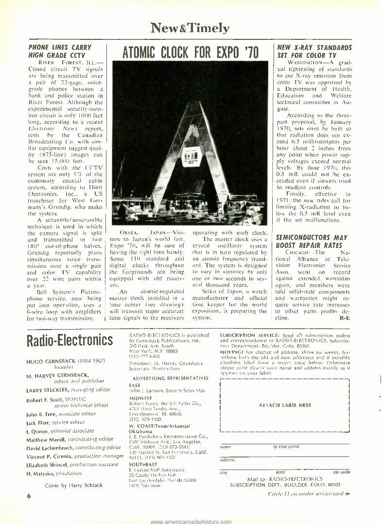
ATOMIC CLOCK FOR EXPO '10
OSAKA, JAPAN -Visi- tors to Japan's world fair, Expo '70, will be sure of having the right time handy. Some 110 standard and digital clocks throughout the fairgrounds are being equipped with uhf receiv- ers.
An atomic- regulated master clock installed in a time center (see drawing) will transmit super accurate time signals to the receivers
operating with each clock. The master clock uses a
crystal oscillator system that is in turn regulated by an atomic frequency stand- ard. The system is designed to vary in accuracy by only one or two seconds in sev- eral thousand years.
Seiko of Japan, a watch manufacturer and official time keeper for the world exposition, is preparing the system.
NEW X -RAY STANDARDS SET FOR COLOR TV
WASHINGTON -A grad- ual tightening of standards to cut X -ray emission from color TV was approved by a Department of Health, Education and Welfare technical committee in Au- gust.
According to the three - part proposal, by January 1970, sets must be built so that radiation does not ex- ceed 0.5 milliroentgens per hour about 2 inches from any point when power sup- ply voltages exceed normal levels. By June 1970, this 0.5 mR could not be ex- ceeded even if viewers tried to readjust controls.
Finally. effective in 1971, the new rules call for limiting X- radiation to be- low the 0.5 mR level even if the set malfunctions.
SEMICONDUCTORS MAY BOOST REPAIR RATES
CHICAGO -The Na- tional Alliance of Tele- vision Electronics Service Assn. went on record against extended warranties again, and members were told solid -state components and warranties might re- quire service rate increases to offset parts profits de- cline. R -E
Radio -Electronics
HUGO GERNSBACK (1884 -1967) founder
M. HARVEY GERNSBACK, editor and publisher
LARRY STECKLER, managing editor
Robert F. Scott, W2PWG senior technical editor
John R. Free, associate editor
Jack Darr, service editor
I. Queen, editorial associate
Matthew Mandl, contributing editor
David Lachenbruch, contributing editor
Vincent P. Cicenia, production manager
Elizabeth Shincel, production assistant
H. Matysko, circulation
Cover by Harry Schlack
RADIO -ELECTRONICS is published by Gernsback Publications, Inc. 200 Park Ave. South New York, N.Y. 10003 (212) 777 -6400
President: M. Harvey Gernsback Secretary: Bertina Baer
ADVERTISING REPRESENTATIVES
EAST john J. Lamson, Eastern Sales Mgr.
MIDWEST Robert Pattis, the Bill Pattis Co., 4761 Vest Touhy Ave., Lincolnwood, Ill. 60646 (312) 679 -1100
W. COAST /Texas /Arkansas/ Oklahoma J. E. Publishers Representative Co., 8380 Melrose Ave., Los Angeles, Calif. 90069, (213) 653 -5841; 420 Market St. San Francisco, Calif. 94111, (415) 981 -4527
SOUTHEAST E. Ludan Neff Associates 25 Castle Harbor Isle Fort Lauderdale. Florida 33308 (305) 566 -5656
SUBSCRIPTION SERVICE: Send all subscription orders and correspondence to RADIO -ELECTRONICS, Subscrip- tion Department, Boulder, Colo. 80302. MOVING? For change of address, allow six weeks, fur- nishing both the old and new addresses and if possible attaching label from a recent issue below. Otherwise please print clearly your name and address exactly as it appears on your label.
ATTACH LABEL HERE
name (please print)
address
city state
Mail to: RADIO -ELECTRONICS SUBSCRIPTION DEPT., BOULDER. COLO. 80302
zip code
6 Circle II on reader service card .
www.americanradiohistory.com

JFD is ready!... 20 million homes are ready!... Get ready...get set...go with new
Home Entertainment JFD Program Center Kits * Provide up to 4 TV sets with different programs -
from 1 antenna. * Beautifully packaged in full -color carry -home display
carton. * Distribution amplifier powerful enough to drive
up to 12 sets - with additional splitters. Whether you install it yourself or sell it over -the -counter, the unique JFD Home Entertainment Program Center Kit gets you in on the ground floor of a lucrative new untapped market - 20 million households with two or more sets that can use a distribution system.
Make every home an nt. = ainment cent
P po rograrm
Center Kit
Operates up to 4 TV sets (plus FM)-all from 1 antenna
Thousands ola home owners, new home owners, contractors, and builders in your area are ready -to -buy prospects for (4)
JFD Program Center Kits
: -'..
SEE YOUR OISTRf6U1O
OR WI RITE FOR OUR PROMOTION KIT
..wrrz Sr.rv 474-4\m,?o 00"!v... Ml>esTau7dT. h.e.v. 111590 .9°e. eANAtrlo? !4TCö .0RyYARi6e, C r.0 e° 1a;q.WS;Ë'd.,MIL,A. ..(.?.. fiad9gòN1eri1 LC3r3 T491T4lC2g 925-07; 641144C4445+"..4@d80. rdaNex6leS,A Mtia
www.americanradiohistory.com

Discover the ease and excitement of learning Electronics with programmed equipment N sen a a wRI, ain
ands r in t
as home
ll we as ith
your N
head. you tr
You learn the WHY of Electronics, Communica-
tions, TV -Radio the NRI pioneering "3- Dimensional" way. NRI training is the result of more than half a century of simplifying, organizing, dramatizing subject matter, and providing personal services unique for a home study school. You get the kind of technical training that gives you priceless confidence as you gain experience equal to many, many months of training on the job.
NRI-The 53 Year Leader in Electronics Training
APPROVED UNDER NEW GI BILL If you served since January 31, 1955, or are in ser- vice, check GI line in postage -free card.
AçHifv£h sv,
ü,£cTltoy,,.z tt¿
8 RADIO -ELECTRONICS
www.americanradiohistory.com

Earn $5 or more an hour spare or full time in
TV- RADIO SERVICING Color Television has arrived. Sales are soaring, along with the continu- ing popularity of other home enter- tainment equipment like portable radios, tape recorders, hi -fi sets, phonographs and auto radios. TV- Radio servicing is one of your best routes to spare -time earnings, a
good paying job or a business of your own. NRI not only trains you quickly and expertly, but also shows you how to get started in Servicing soon after you enroll, earning as you learn. NRI trains you in today's methods of installing and repairing all Electronic equipment for the home -including booming Color TV. You even build, experiment with and keep to enjoy your own solid -state radio and your choice of black -and- white or Color TV receiver. Like thousands of others, you can be earning $5 or more an hour extra in spare time starting soon.
There's money and success awaiting you in
BROADCASTING - COMMUNICATIONS The experience you gain from in- tensely practical NRI training in Complete Communicatdons equals as much as two years of training on the job. With NRI, you can train fora choice of careers ranging from mo- bile, marine and aviation radio to TV broadcasting and space commu- nications. You learn how to install, maintain and operate today's re- markable transmitting and receiving equipment by actually doing it. You build and experiment with test equip- ment, like a VTVM you keep. You build and operate amplifier circuits, transmission line and antenna sys- tems, even build and use a phone -cw transmitter suitable for transmission on the 80 -meter amateur band. Whichever of five NRI Communica- tions courses you choose, you pre- pare for your FCC License exams, and you must pass your FCC exams or NR1 refunds your tuition in full.
Move ahead in America's fast growing industry as
ELECTRONICS TECHNICIAN Electron ics touches everyone's lives. This vast field of opportunity is open to you with NRI training. Industrial/ Military Electronics training -like all NRI courses -prepares you quickly, thoroughly the practical "hands on" way. You build with, and learn to un- derstand the functions of, today's miracle solid -state components like printed circuits, diodes and transis- tors. You build and experiment with Electronic circuitry used in automa- tion, data processing, ultrasonics, telemetry. Whatever your interest in Electronics, NRI training can fill your needs. Prove to yourself what nearly a million NRI students could tell you ... that you get more for your money from NRI. Check the postage -free card and mail it today for your FREE NRI Color Catalog. No salesman will call. NATIONAL RADIO INSTITUTE, Electronics Division, Washington, D.C. 20016.
YOU GET MORE FOR YOUR MONEY FROM NRI_ Build, test, explore, discover. Everything you see here is included in one NRI course -including Color TV. Other courses equally complete. And you'll be surprised at the low tuition costs. Text for text, kit for kit, dollar for dollar -you get more for your money from NRI.
NOVEMBER 1969
www.americanradiohistory.com

THROW AWAY THE SOLDER
or MY DADDY USES CUSS WORDS
Some years ago two men, Mr. S. and Mr. deC had an idea. Wearing white hats they dutifully offered it to the giant electronics conglomerate under whose roof they laboured. He sneered so they left and developed it on their own.
It's a solderless breadboard and the secret lies in a precision clip of firm grasp and low resistance. These clips are leafspring con- tacts of phosphor bronze or silverplate.
As with all good things customers came up with more ideas using S -DeCs than the originators believed possible and the demand for added flexibility resulted in a
box with two interlocking S -DeCs known as DeCSTOR, (pronounced Deck -Store). Not content with this, users circuits out- grew the DeCSTOR and so a 4 -DeC kit was created for the man with ideas big- ger than his breadboard. Today there is a whole range of DeC solderless bread- boards covering conventional and inte- grated circuit requirements.
So, if you need to throw away the solder, keep the skin on your fingers and the black words buried down below, write to us for more information, or better still send us a check.
INTRATEC 399 Jefferson Davis Highway Arlington, Virginia 22202 Please send me postage paid:
S -DeC's @ S 6.75 each DeC STOR's @ $13.75 each
4 -DeC's @ $23.25 each I
State Zip Code I
Box RE I
i enclose a check /money order for 5
Va. residents add 4% sales tax I am interested in the literature and prices.
IC versions. Send
Name
Address
City
Circle 13 on reader service card 12
LOOKING AHEAD (continued from page 2)
Pictures from FM stations The FCC has been asked to authorize tests of TV picture
transmission from an FM station in a trial of a special educa- tional service. The pictures would be sent by slow -scan tech- niques (no motion could be shown) on a 5 -kHz subcarrier of a Flint, Mich., educational FM outlet. Other subcarriers of the same station would transmit audio educational material, while the main channel would carry the station's normal program- ming. Educasting Systems, Inc., which has requested the test, would supply specially modified television receivers for the TV -FM broadcasts. Pushbuttons on the receiver would permit students to answer questions asked by the instructor. The vari- ous subcarriers, selected by the pushbuttons, would tell students whether their replies were correct or incorrect, and why.
SCA receiver ban The FCC, in a surprise action, has banned the sale of SCA
(multiplex) receivers by a retail and mail -order chain to gen- eral consumers. Armed with a Justice Department opinion, the Commission obtained agreement by Lafayette Radio to stop selling radios designed to receive Subsidiary Communications background music subcarrier transmissions. The Justice Depart- ment said that unauthorized use of private transmissions was illegal when the listener derives a "gain" from it -the "gain" in this case presumably being enjoyment of music. Previous FCC advisory opinions had indicated that the Commission saw no law violation in consumer reception of SCA transmissions.
FM dominates radio The dream that frequency modulation some day would be
the dominant force in radio has finally been realized. For the first time in history, Americans are buying more FM- equipped than AM -only radios. In this year's second quarter, the cross- over became apparent. Of 8.9 million table, clock and portable radios sold in the United States, 4.6 million (or 51.9% ) had FM.
Thus the common garden variety home and portable radio has now joined the more sophisticated component tuner and the radio -phonograph or TV combination in converting to FM. The only radio field which is still a virtual AM monopoly is auto radio -but even this is gradually changing. In 1968, about 11% of car radios sold had FM. The share inched up to 13% in the first half of this year.
Government X -ray standards Agreement has been reached between the government's
Bureau of Radiological Health and a government- industry- public advisory committee on standards for radiation for color sets, involving a progressive tightening of permissible limits. As of next Jan. 1, no receiver may radiate more than 0.5 milli - roentgens per hour (mR /hr.) as measured at 5 centimeters (about 2 inches) from any surface of the outside of the set with line voltage at130 and all user controls set for maximum radia- tion.
Beginning June 1, the same limits will apply, but with ser- vice controls set so as to produce maximum radiation. And, as of June 1, 1971, the 0.5 -mR limit will be enforced with receivers doctored to simulate failure of components or circuits (shunt regulator, etc.) to increase radiation. Television set manu- facturers, now concentrating on introducing such fail -safe com- ponents as solid -state high -voltage rectifiers, feel that they can meet this schedule.
The next X -ray standard to be propounded by the Bureau is expected to set limit on radiation of receivers during servic- ing, for the protection of technicians. R -E
RADIO -ELECTRONICS
www.americanradiohistory.com

will tell you everything!-Complete Specs including schematics! Am_
MARK lEN® SCR CAPACITIVE DISCHARGE IGNITION SYSTEM Now discover for yourself the dramatic improiement in performance of yotr car, camper, jeep, truck, boat - any vehicle Delta's remarkable electronic achievement saves on gas, promotes better acceleration, gives your car that zip you've always wanted. Find out why even Detroit has finally come arounc. In five years of proven reliability, Delta's Mark Ten has set new records á ignition benefits. No re- wiring! Works on litera ly any type of gasoline engine. A Dramatic Increase in Performance and
in Fast Acceleration A Promotes More Complete Combustion
KIT FORM 95 124 ONLY
r
MODEL 3000 FET VOM ONLY
$1495,,. Delta now offers a compact, versatile, and e><tremely sen-
sitive VOM which combines FETs and ICs for extreme accuracy. Compact (61/2"W x 8 "H x 31/2"D), portable. Wt.
33/4 lbs.
IN KIT FORM: Feedback network with pre -selected corn -
porents to eliminate all final calibration. Ready to use
when assembled!
NEW DELTA FEATURES:
Mirror scale 200 A D'Arsonval meter
litegrated circuit (IC) operational amplifier for extreme accuracy FET input stage with current regulator Two stage transistor current regulator and Zener diode on OHMS for absolute stability aid accuracy Voltage clippers for protection of input stage
Poirts and Plugs Last 3 to 10 Times Loner Up -o 20% Mileage Increase (saves gas)
ASSEMBLED $4495 ONLY
ppd.
Only $95 V V ppd.
A Fully temperature compensated for low low zero drift Ten turns ZERO and OHMS adjust potentiometers Epoxy glass circuit boards and metal case
A Enclosed switches Uses readily available type AA cells
Uses standard test leads for maximum flexibility and ease of measurement
10 Megohms input impedance
r DELTA: Please send me literature immediately.
I am enclosing $ for items checked.
Mark Ten SCR (0 Kit Assembled)
Model 3000 FET VOM ( Kit Assembled) ] Computach (Kit only)
Please ship immediately.
Name
Address
City Stole Zip
*My ca- is (Modell (Year)
L
1
C:
=1'117AM Delta, pioneers in CD ignition who pro- duced the fabulous MARK TEN'S, now offer a precise computer- tachometer which obso-
letes any type tachometer on the market today! You achieve unbelievable accuracy in RPM readings due to the advanced, solid -state electronic matched components used in the computer, coupled with the finest precision meter in the world. Works on all 2, 3, 4, and 6 cylinder 2 cycle and with 4 -6 -8 cylinder-4 cycle 12 volt engines,
Write today for complete literature packet
OP
9.0
DELTA PRODUCTS, INC.
C -8000 RPM range
A Ferfect linearity - zero paralax A adjustable set pointer
wide angle needle sweep
Translucent illuminated dial
Chrome plated die -cast housing
AI -angle ball & socket mounting Use it with ANY ignition systen Meter: 3 , e dia. X 33" deep
A Calibration kit included, no test egpt. needed.
*An exclusive tachometer for ise RPM measurement in Easy --o -build Kit form! pK d.
KIT FORM ONLY
D[lTA P.O. BOX 1147 GRAND JU4CTION, COLORADO 8150 Circle 14 on reader service card
NOVEMBER 1969 13
www.americanradiohistory.com

u der ris -ed?
I IARDLY! This QUAM speaker is thinner and lighter than most, but there's nothing scrawny about its sound or emaciated about its performance.
14
It's one of 25 models in the Quam line that's being fed a special diet ... an exclusive new high energy magnet material we call Q /8.
Q/8 provides more gap energy for less weight, so a .65 ounce magnet gives you the same per- formance as a full ounce of Alnico V. Ideally suited to Quam's high density cup -pot structure, Q/8 slims the speaker down in contour as well as weight -while delivering full, robust sound.
Q/8 magnets are exclusively available today on Quam speakers -part of our ongoing program of nourishing our customers first with the finest.
QU -always the Quality Line, for every speaker need.
QUAM -NICHOLS COMPANY 234 East Marquette Road Chicago, Illinois 60637
Circle 15 on reader service card
In the Shop ...With Jack By JACK DARR
SERVICE EDITOR
TRANSISTOR TESTING: WHAT WITH? ONE FELLOW SAYS "AN OHMMETER'S not worth a darn for transistor test- ing! I like a curve -tracer."
Another one says, "Nay, nay. In- circuit beta -tester is the only thing that'll give you good results!"
The truth of the matter is that almost any kind of test equipment will give you some results in transistor testing. It depends on how you use it and how you interpret the results. There's no such thing as a Universal Tester for solid -state stuff.
Plain old ohmmeter The first and probably the most
frequently used is the ohmmeter. You can get a lot of dope in a hurry with an ohmmeter. The No. I test is strict- ly a "bang- bang" check on any me- dium- resistance range. Take a reading from any element to any other; then reverse the prods. This reverses the polarity of the ohmmeter battery (Fig. 1). So you get a low resistance reading (forward -biased junction) one way, and a high -resistance reading (back- biased junction) the other.
Due to the wide variation of transistor resistances, and the differ- ence in ohmmeter battery voltages, there's no such thing as a standard resistance. So, all you need to look for is "High one way, Low the other." Very low or zero resistance both ways -it's shorted. OR! There is some- thing shunted across it, in the circui- try under test.
Check the schematic, if available. If not, yank the transistor out and re- check. If you get this kind of reading out -of- circuit, it IS shorted.
Don't set the ohmmeter on too high a range. The X100 scale is a good compromise setting. On a batch of typical transistors, I got low read- ings from 1,000 ohms to 5,000 ohms, and 15,000 ohms up to 50- 60,000 ohms on high. You hear repeated warnings about using an ohmmeter on transistors, for fear of blowing the transistor with the ohmmeter battery voltage. I won't say it can't happen, but it has never happened to me. Pos- sibly the series resistance inside the ohmmeter limits the current to a very low value. It's current which blows transistors.
One thing you do need to know is the polarity of your ohmmeter bat- tery. In many older vom's and some vtvm's, the red lead was always nega- tive. Most late models have the red lead positive. If you know which is which, you can find out the sex of any transistor with a simple test.
Put the ohmmeter negative lead on the base. If this is a pnp device, you'll read a low resistance to both collector and emitter. Reversing the
OHMMETER
prods; high resistance to both. If it's an npn, putting the positive lead to the base will give you low resistance to collector and emitter. Reverse the prods; both high. You automatically check for internal shorts at the same time, of course.
Measuring leakage Now comes the real bugaboo -
leaky transistors. In germanium tran- sistors, a small amount of leakage is OK. With silicons, so popular now in rf, i.f. and even of stages -none. Zero!
Leakage must be read with the transistor out -of- circuit and on an ac- curate leakage- tester. Any of the bet- ter modern in- circuit out -of- circuit transistor testers will read it.
Leakage problems show up in TV agc; agc- controlled i.f.'s; direct -
(continued on page 16)
RADIO -ELECTRONICS
www.americanradiohistory.com

Just one little mistake... and you're washed up!
That's the way it is at Channel Master.
If a color picture tube's screen doesn't pass pre - cisior inspection in 1 -2 -3 order...green. blue, and red...it's sent back for a complete acid wash -up.
We'll start all over again.
Even cur new extra bright gadolinium rare earth phosphors at $120 a pound go right down the drain when ¿ color screen isn't up to standard.
Regardtiess of cost, we protect Channe' Master's
reputation for producing' Color CRTs that equal or
exceed industry standards.
That's just one of the reasons why you find Channel Master CRTs in some of today's finest new color sets. It's also why you can point with pride to the Channel Master name on replacement color tubes.
Call your Channel Master Distributor. He's your complete Picture Tube Headquarters.
At Channel Master YOUR Reputation is OUR Business.
CHANNEL MASTER® DIVISION OF AVNET, INC., ELLENVILLE, NEW YORK 12428
Circe 16 on reculer service card NOVEMBER 1969 15
www.americanradiohistory.com
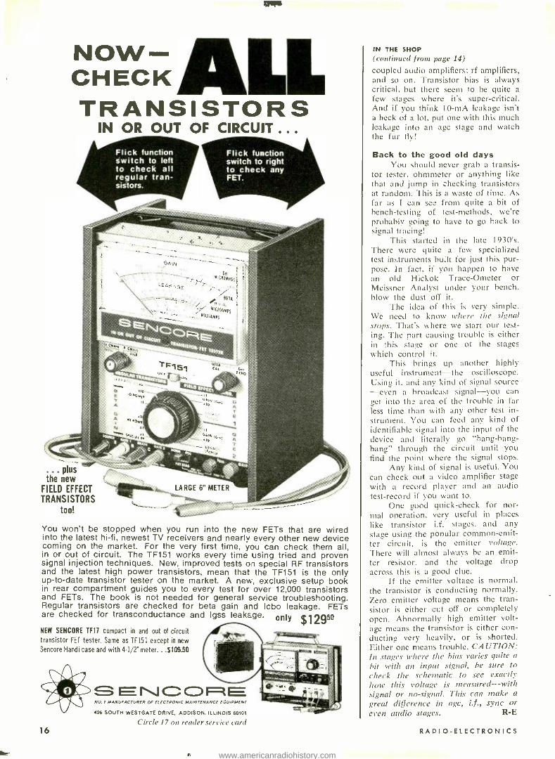
NOW - CHECK TRANSISTORS
IN OR OUT OF CIRCUIT .. .
Flick function switch to left to check all regular tran- sistors.
Flick function switch to right to check any FET.
plus the new
FIELD EFFECT
TRANSISTORS too!
You won't be stopped when you run into the new FETs that are wired into the latest hi -fi, newest TV receivers and nearly every other new device coming on the market. For the very first time, you can check them all, in or out of circuit. The TF151 works every time using tried and proven signal injection techniques. New, improved tests on special RF transistors and the latest high power transistors, mean that the TF151 is the only up -to -date transistor tester on the market. A new, exclusive setup book in rear compartment guides you to every test for over 12,000 transistors and FETs. The book is not needed for general service troubleshooting. Regular transistors are checked for beta gain and Icbo leakage. FETs are checked for transconductance and Igss leakage.
NEW SENCORE TF17 compact in and out of circuit transistor FET tester. Same as TF151 except in new
Sencore Handi case and with 4 -1/2" meter.. .$109.50
16
NO I MANUFACTURER OF ELECTRONIC MAINTENANCE EQUIPMENT
426 SOUTH WESTGATE DRIVE, ADDISON. ILLINOIS 60101
Circle 17 on reader service card
IN THE SHOP (continued from page 14)
coupled audio amplifiers; rf amplifiers, and so on. Transistor bias is always critical, but there seem to be quite a
few stages where its super -critical. And if you think 10 -mA leakage isn't a heck of a lot, put one with this much leakage into an age stage and watch the fur fly!
Back to the good old days You should never grab a transis-
tor tester. ohmmeter or anything like that and jump in checking transistors at random. This is a waste of time. As far as I can see from quite a bit of bench -testing of test- methods, we're probably going to have to go back to signal tracing!
This started in the late 1930's. There were quite a few specialized test instruments built for just this pur- pose. In fact, if you happen to have an old Hickok Trace -Ometer or Meissner Analyst under your bench, blow the dust off it.
The idea of this is very simple. We need to know where the signal stops. That's where we start our test- ing. The part causing trouble is either in this stage or one of the stages which control it.
This brings up another highly useful instrument -the oscilloscope. Using it, and any kind of signal source -even a broadcast signal -you can get into the area of the trouble in far less time than with any other test in- strument. You can feed any kind of identifiable signal into the input of the device and literally go "hang -hang- bang" through the circuit until you find the point where the signal stops.
Any kind of signal is useful. You can check out a video amplifier stage
with a record player and an audio test -record if you want to.
One good quick -check for nor- mal operation. very useful in places like transistor i.f. stages, and any stage using the popular common -emit- ter circuit, is the emitter voltage. There will almost always be an emit- ter resistor. and the voltage drop across this is a good clue.
If the emitter voltage is normal, the transistor is conducting normally. Zero emitter voltage means the tran- sistor is either cut off or completely open. Abnormally high emitter volt- age means the transistor is either con- ducting very heavily, or is shorted. Either one means trouble. CAUTION: In stager where the bias varies quite a
hit with an input signal, be sure to check the schematic to see exactly how this voltage is measured -with signal or no- signal. This can make a
great difference in agc, i.f., sync or even audio stages. R -E
RADIO -ELECTRONICS
www.americanradiohistory.com

Castle, the pioneer of television tuner overhauling, offers the following services to solve ALL your television tuner problems.
OVERHAUL SERVICE - All makes and models. UNIVERSAL REPLACEMENTS
Prefer to do it yourself?
Castle universal replacement tuners are available with the following specifications.
VHF or UHF tuner $9.95
UHF -VHF combination (one piece chassis) $9.95 TRANSISTOR tuner $9.95
COLOR tuner $9.95 (Guaranteed color alignment ... no additional charge)
Overhaul includes parts, except tubes and transistors.
Simply send us the defective tuner complete; include tubes, shield cover and any damaged parts with model number and complaint. Your tuner will be expertly overhauled and returned promptly, performance restored, aligned to original standards and warranted for 90 days. UV combination tuner must be single chassis type; dismantle tandem UHF and VHF tuners and send in the defective unit only. And remember -for over a decade Castle has been the leader in this specialized field . . . your assurance of the best in TV tuner overhauling.
CUSTOM REPLACEMENTS Exact replacements are available for tuners that our inspec- tion reveals are unfit for overhaul. As low as $12.95 ex- change. (Replacements are new or rebuilt.)
NOVEMBER 1969
STOCK No. HEATERS
SHAFT Min.* Max.*
I.F. OUTPUT Snd. Pic. PRICE
CR6P Parallel 6.3v 13/4ri 3" 41.25 45.75 8.95
CRIS Series 600mA 13/4rr 3" 41.25 45.75 9.50
CR9S Series 450mA 13/4rr 3" 41.25 45.75 9.50
CR6XL Parallel 6.3v 21hrr 12" 41.25 45.75 10.45
CR7XL Series 600mA 21/2,r 12" 41.25 45.75 11.00
CR9XL Series 450mA 21/2r, 12" 41.25 45.75 11.00
*Selector shaft length measured from tuner front apron to extreme tip of shaft.
These Castle replacement tuners are all equipped with memory fine tun- ing, UHF position with plug input for UHF tuner, rear shaft extension and switch for remote control motor drive ... they come complete with hard- ware and component kit to adapt for use in thousands of popular TV
receivers.
Order universal replacements out of Main Plant (Chicago) only.
CASTLE TV TUNER SERVICE, INC. MAIN PLANT: 5715 N. Western Ave., Chicago, Illinois 60645
EAST: 41 -96 Vernon Blvd., Long Island City, N.Y. 11101 Circle 18 on reader service cam
17
www.americanradiohistory.com

We pack your electronics course with kits to make your training fast. You'll enjoy every minute of it.
Your NTS success package Choose a career in electronics: Computers. Color TV Servicing. Automation. Communications. Whatever the field, NTS has a complete home -study package to get you to the top faster. 10 thor- ough training courses. Each in- cludes everything to give you the working knowledge required of successful technicians.
NTS Project -Method Train rg 's the practical way to learn elec-
18
tronics. It's a proven combination of lessons and the best profes- sional kit equipment available. NTS provides the biggest selec- tion of kits ever offered in home - study . . . all at no extra cost. You'll construct these exciting kits to fully understand electronic circuits, components, and con- cepts. Our Project- Method lets you build skills by putting theory into practice ... by working with your hands, as well as your head.
The NTS "learn and practice" ap- proach makes training at home really easy. All it takes is a few hours a week ... whether you're starting from scratch or in ad- vanced courses.. This is the all - inclusive success package that put thousands cf men into the best paying jobs . .. or into their own business. If "just a living" isn't good enough for you, now is the time to get something better going for you!
RADIO -ELECTRONICS
www.americanradiohistory.com
NTS COMPUTER ELECTRONICS This is the future. And it's hap- pening now. The number of com- puters will increase many times in the next few years.
Exclusive new Compu-Trainer
offers a solid grounding in computer operation, wiring, data processing and programming. One of the 10 important kits in- cluded is our exclusive Compu- Trainer ®. It's a fully operational computer logic trainer - loaded with integrated circuits - the first ever offered in home study. It in- troduces you quickly to how, what, when and why of computers ... from theory to practical serv- icing techniques. This unit is capable of performing 50,000 op- erations per second. And it's sent at no extra cost.
NTS COLOR TV SERVICING This is a broad, easily understood
COLOR TV 295 SQ. IN. PICTURE
program designed to make you a complete home -entertainment service technician. Included, at no extra cost, is a color TV that has more features than any
NOVEMBER 1969
set on the market. You also learn all about stereo, hi -fi, multiplex systems, and become a specialist in Color TV Servicing. Kits also include AM -SW radio, solid -state radio, field- effect transistor volt - ohmmeter, electronic tube tester.
NTS AUTOMATION¡ INDUSTRIAL ELECTRONICS You're trained in the "push -but- ton" electronics that keep indus- try going and growing ... from relay type controls to highly advanced systems essential to production. You receive 16 kits in- cluding a 5" wide band oscillo- scope, and the new NTS elec- tronics lab: a
fascinating NTS exclusive experi- mental laboratory. A complete workshop which makes you familiar with solid - state, miniature, and integrated circuits.
5" Oscilloscope
NTS ELECTRONIC COMMUNICATIONS The use of 2 -way radio systems in private and commercial applica- tions is skyrocketing. NTS pre- pares you for the big -money opportunities in the field of trans- mitting and receiving equipment. Your tuition will be refunded in full if you cannot pass the FCC exam for a 1st Class Commercial Radio- Telephone License within
5 Watt AM Transmitter & Receiver
six months after successfully completing this course. You build valuable kits including Amateur - Phone 6 Meter VHF Transceiver, solid -state Radio , and a field -
effect transistor volt- ohmmeter.
CLASSROOM TRAINING AT LOS ANGELES You can take classroom training at Los Angeles in sunny Southern California. NTS occupies a city block with over a million dollars in facilities devoted exclusively to technical training. Check box in coupon.
NATIONAL TECHNI4C AL SCHOOLS World -Wide Training Since 1905
4000 South Figueroa Street Los Angeles, Calif. 90037, U.S.A.
APPROVED FOR VETERANS Accredited Member: National As- sociation of Trade and Technical Schools, National Home Study Council.
r TODAY, MAIL COUPON FOR FREE COLOR CATALOG AND SAMPLE LESSON.
NTS GUIDE
ELECTRONICS
NATIONAL TECHNICAL SCHOOLS 4000 S. Figueroa St., Los Angeles, Calif. 90037
Please rush Free Color Catalog and Sample Lesson, plus information on field checked below. No obligation. No salesman will call.
MASTER COURSE IN COLOR TV SERVICING COLOR TV SERVICING MASTER COURSE IN TV & RADIO SERVICING PRACTICAL TV & RADIO SERVICING MASTER COURSE IN ELEC- TRONIC COMMUNICATIONS FCC LICENSE COURSE MASTER COURSE IN ELEC- TRONICS TECHNOLOGY INDUSTRIAL AND AUTOMATION ELECTRONICS COMPUTER ELECTRONICS BASIC ELECTRONICS
Name Age
Address
City State Zio Check if interested in Veteran Training under new G.I. Bill. Check if interested ONLY in Classroom Training at Los Angeles. Dept. 206 -119 J
21
www.americanradiohistory.com

clever Kieps Test probes designed by your needs - Push to seize, push to release (all Kleps spring loaded). Kleps 10. Boathook type clamp grips wires, lugs, terminals. Accepts banana plug or bare wire lead. 43/4" long. $1.19 Kleps 20. Same, but 7" long. $1.39 Kleps 30. Completely flexible. Forked -tongue gripper. Accepts banana plug or bare lead. 6" long. $1.47 Kleps 40. Completely flexible. 3- segment auto- matic collet firmly grips wire ends, PC -board terminals, connector pins. Accepts banana plug or plain wire. 61/4" long. $2.39 Kleps 1. Economy Kleps for light line work (not lab quality). Meshing claws. 42" long. $ .99 Pruf 10. Versatile test prod. Solder connec- tion. Molded phenolic. Doubles as scribing tool. "Bunch" pin fits banana jack. Phone tip.
Pruf 10 53/z" long. $ .79 All in red or black - specify .
For additional information, write for our com- plete catalog of - test probes, plugs, sockets, connectors, earphones, headsets, and minis-
eture components.
Available through your local distributor, or write to: RYE INDUSTRIES, INC.
I N D U S T R I E S 130 Spencer Place, Mamaroneck, N.Y. 10543
Kleps 30 Kleps 40
Kleps 30
Cir(lc 20 on reader service card
America's Top -Rated Stereo Kits Now a Best Buy!*
*LT- 1l2ß -1 FM Stereo Monitor Tuner Kit: Now $149.95
LK -60B 160 -Watt Stereo Amplifier Kit: Now $149.95
LR -88 135 -Watt AM /FM Stereo Receiver Kit: Now $299.95
Ca SCOTT Write for new Scott Kit Catalog. H. H. Scott, Inc., III Powdcrmill Road, Maynard, Mass. 01754. © 1969, H. H. Scott, Inc.
POPULAR SCIENCE SAYS: . How does it perform? In a
word, flawlessly; stereo performance is superb, and the set's sensitivity will cope with the deepest fringe -area reception conditions . I rate the LT -112B as one of the finest FM tuners available - in or out of kit form." STEREO REVIEW SAYS: "We measured the IHF sensitivity of the Scott LT -112B tuner as 1.4 microvolts, which certainly makes it one of the most sensitive tuners we have encountered." AMERICAN RECORD GUIDE SAYS: "Scott LT -112B tuner must be placed in the very top echelon of today's components." AUDIO SAYS: "Here's a stereo FM /AM receiver kit with a real hot front end, fairly high power output, low distortion, and ex- cellent operating flexibility ... The Scott LR -88 offers a most competent design at a price well below that for an equivalent factory -assembled unit." ELECTRONICS ILLUSTRATED SAYS: "One of the finest examples of solid - state integrated -amplifier kit design, packaging and performance we have seen in the Scott LK -60." HIGH FIDELITY SAYS:
. an unprecedented high sensi- tivity, one which surprised even us
. This is certainly a tuner for use in the most difficult of reception areas; stations seem to pop in all across the tuner dial."
Circle 100 on reader service card
orrespondence
REPAIR VS. DESIGN
In your August issue Jack Darr, in his "In The Shop . . . With Jack" article, indicates that technicians should he called "service engineers" because "they do engineering work." He goes on to describe the work of a TV repairman.
The author makes a big mistake in comparing the two professions. No- where in his article does he indicate that the repairman does any engineer- ing work. Instead, he is busy compar- ing what he finds (trouble) with the indications he should find, and isolates the problem. This is not engineering.
The work of an engineer is to do the original circuit design. It is the en- gineer who tells the technician what the circuit should do in the first place.
If the technician feels that he has enough knowledge to design a TV set, let him do it and be titled "engineer." There is enough need in industry to- day for engineers that any qualified applicant will be accepted. But let those who repair and fix be called by the time -honored title, "technician." In this time when the title "engineer" is being abused by so many people, let those who should know better refrain from this practice.
JOHN PRITCHETT, Electronic engineer,
Altec Lansing
WANTS MORE DARR
l've been reading Jack Darr's "In The Shop . . . With Jack" for several years, and think he does an excellent job of making difficult ser- vicing problems easy to understand for beginners like myself. Does he have any books published, and could you give me all the titles?
N. VELEZ -CASANOVA Mayaguez, P.R.
Mr. Darr begins his 10th year with us in January simplifying tough problems on a regular basis. Listing all his hooks, though, might take more room than we have here. In- stead, for a starter, write: Howard W. Sams & Co., Inc., 4300 W. 62 St., Indianapolis, Ind. 46206; or, TAB Books, Blue Ridge Summit, Pa. 17214.
(continued on page 24)
22 RADIO -ELECTRONICS
www.americanradiohistory.com

smooth RCA WP -700A, 702A, 703A and 704A constant voltage dc power supplies are all solid- state. A negative feedback circuit maintains constant output voltage with low ripple - regardless of varying line. In fact, at rated load, these supplies are so smooth that they hardly cause a ripple." They are versatile bench -type units -ideally suited for use in circuit design, servicing, industrial, and educational applications. Output voltage of the WP -700A and WP -702A is continuously adjustable from 0 to 20 volts at current levels up to 200 mA. Output voltage of the WP -703A is continuously adjustable from 0 to 20 volts at current levels up to 500 mA. Output voltage of the WP -704A is continuously adjustable from 0 to 40 volts at current levels up to 250 mA. All four power supplies have built -in electronic short -circuit protection - and a front panel overload- indicator that signals approach to maximum rated current level.
WP -700A: $40.00* (five or more) $48.00* (less than five)
w WP -703A: $49.00* (five or more) $58.00° (less than five) WP -704A: $49.00'' (five or more) $58.00* (less than five)
NNW
'Optional Distributor Resale Price. w
WP -702A: Siamese Twins of WP -700A. but electrically isolated $73.00° (five or more) $87.00' (less than five)
For further information write: RCA Electronic Components, Commercial Engineering, Department K39W, Harrison, N. J. 07029. Look to RCA for instruments to test /measure /view /monitor /generate
Circle 22 on reader service card NOVEMBER 1969
l 23
www.americanradiohistory.com

You never saw a scope like this
for twice $229. Leader's five -inch LBO -538 has a bandwidth running from DC to 10MHz. (About twice the bandwidth of any other scope in the same price range.)
Its sensitivity rating is 10 mv/cm or better. (About half -again the sensitivity of any other scope in the same price range.)
It has FET vertical and horizontal inputs, directly coupled with push -pull amplifiers for no- distortion display. (You won't find that on any other scope
1,.00,538 OSCILLOSCOPE
for the money.) It's the perfect test
companion for Leader's LCG -388 color bar gener- ator, The only one that's perfectly stable, the instant you turn it on.
The LBO -53B: only $229, and now you know what we mean about never seeing a scope like it for twice the price.
At your distributor's, along with the LCG -388 and other Leader test in- struments. For the distrib- utor nearest you, just drop a line or call.
Seeing is believing. LEADER INSTRUMENTS CORP.
24 -20 Jackson Avenue, Long Island City, N.Y. 11101 (212) 729 -7411 Circle 23 on reader service card
Build this pipelike Schober Recital Organ for only $1850!*
You couldn't touch an organ like this in a store for less than $4,000 -and there never has been an electronic instrument with this vast variety of genuine pipe -organ voices that you can add to and change any time you like! All four families of formal pipe tones are present in variety to delight players of classic and religious music. Yet you can change the entire organ for popular and theatrical sounds, or plug in special voices for baroque, romantic, or modern repertoires. If you've dreamed of the sound of a large pipe organ in your own home, if you're looking for an organ for your church, you'll be more thrilled and happy with a
Schober Recital Organ than you could possibly imagine -kit or no kit.
You can learn to play it -and a full -size, full -facility instrument is easier to learn on than any cut -down "home" model. And you can build it, from Schober Kits, world famous for ease of assembly without the slightest knowledge of electronics or music, for de- sign and parts quality from the ground up, and -above all -for the highest praise from musicians everywhere.
Send right now for the full -color Schober catalog, containing specifications of all five Schober Organ models, beginning
at $499.50. No charge, no obligation. If you like music, you owe yourself a Schober Organ!
Includes finished walnut console. (Only $1446 if you build your own console.) Amplifier, CITY STATE 7IP
speaker system, optional accessories extra. ,L Circle 24 on reader service card
The 9ChdeitOrgan Corp., Dept. RE -72 43 West 61st Street, New York, N.Y. 10023
Please send me Schober Organ Catalog and free 7 -inch "sample" record.
Enclosed please find $1.00 for 12 -inch L.P. record of Schober Organ music.
NAME
ADDRESS
24
CORRESPONDENCE (continued from page 22)
DOUBTFUL DIGITS
Somehow I doubt if many of your readers will rush to construct that $250 IC digital clock described in your September issue. I would say that article is the zenith (or perhaps nadir) of expensive absurdity in con- struction articles. I just can't see the advantage of such a clock in view of the mechanical numeral clocks on the market that do the same thing for one -tenth the cost.
Surely a simpler and less expen- sive clock with numeral readout tubes could be constructed using inexpen- sive clock and timing motors driving low- friction rotary switches to acti- vate the tube circuits.
KEN GREENBURG Chicago, Ill.
We felt many of our readers would like to tackle such a project, Ken, so we asked for comments in an April 1969 article (page 23). Based on the hundreds of enthusiastic re- quests, we decided to run it. We'd still like to have other opinions.
There's no doubt about your second point, but we preferred an electronic to an electromechanical version- they're considerably more re- liable.
TV CAMERA ERRORS
I discovered the following mis- takes while going over the TV camera article in your July issue:
Resistor R52 is 222K in the parts list and 220K on the schematic. Isn't 220K the correct value?
The parts list indicates C39 as a 0.1 µF, 400V. Its marked 1000 µF on the schematic, which I believe cir- cuit specifications call for. Right?
You have two C45's listed: one in the horizontal scan and one in the video amplifier. I discovered the hori- zontal scan C45 is in reality C43.
Incidently, I've found an old Army ammo can is perfect for the chassis. I was all set to suggest such a project, and I thank you for the opportunity to build such a camera.
FRANCIS E. FULLER Fort Monmouth, N.J.
You're right on all counts, Fran- cis. Also, there should he a dot indi- cating a connection between C30, C31, C29 and Q16's collector. R -E
NEXT MONTH The new solid -state antenna rotators are described in November by R -E's technical editor. Find out how they work to help pull in
better signals for TV.
RADIO -ELECTRONICS
www.americanradiohistory.com

Our hot ones are the last to go. The last thing you need is to be
called back a day or two after you've replaced the sweep or high voltage tubes in somebody's color TV.
But, they're usually the first to go. Because they get so hot. So we figured out how to cool them. Now, they last a lot longer. Take our 6JE6C /6LQ6, for ex-
ample. It's the horizontal deflection tube that takes such a beating when the set gets hot.
NOVEMBER 1969
Well, we've given it special patent- ed radiator fins that first absorb the heat and then radiate it out of the tube.
Now it runs cooler and lasts longer. Same for our 6JS6C. Or take our 6BK4C /6EL4A.
That's the shunt regulator that elim- inates runaway high voltage. We gave this one a whole new anode and shield design to improve heat transfer and stability.
Circle 25 on reader service card
Now it also runs cooler and lasts longer.
Or take our 3Á3B high voltage rectifier. This one's got leaded glass for added protection. And it lasts longer too.
So next time you have to replace any of the hot ones, just cool it. You'll both last longer.
SYLVAN IA GENERAL & ELECTRONICS
25
www.americanradiohistory.com

Excelsior!*
We couldrit leave well enough alone
We have improved the trackability of the V -15 Type II in the bass and mid -range registers -- without affecting its redoubtable treble. Result: where, in the past, you may have been required to increase track- ing forces to track heavily modulated bass drum, tympani, organ pedal, bassoon, tuba, or piano pas- sages ... you can now play these passages without increasing tracking force, without bass flutter or IM distortion ... and significantly increase record and stylus tip life. Only $67.50 for the world's highest trackability cartridge.
* Latin: always upward
6
6
V -15 TYPE II (IMPROVED)
ORIGINAL V -15 TYPE II
too
26
TRACKABILITY CHART (1 GRAM STYLUS FORCE)
-4 V -15 TYPE II (IMPROVED)
YOU CAN MODIFY YOUR PRESENT V -15 TYPE II . .
You may attain this higher bass and mid -range trackability by installing the IMPROVED VN15E stylus at $27.00. Look for the word "Shure" in red letters on the stylus grip.
SI--IVRE SUPER TRACKABILITY PHONO CARTRIDGE
01969, Shure Brothers Inc., 222 Hartrey Ave., Evanston, Illinois 60204
Circle 26 on reader service card RADIO -ELECTRONICS
www.americanradiohistory.com
Earn Your DEGREE in Electronics! Grantham School of Engineering offers an educational program leading to the Degree of Associate in Science in Electronics Engineering - the ASEE. Beginners in electronics must take resident classes in Hollywood, Calif., or in Washington, D.C. However, experienced electronics technicians may com- plete the entire degree program by home study, except for the final two weeks which must be taken in Hollywood. There are three different ways the program is offered, referred to as Daytime -Resi- dence, Supplemented- Correspondence, and Home Study. Each method is discussed below.
Daytime- Residence
The Daytime- Resident program is designed for beginners. You may enroll in Hollywood or Washington. Classes meet five days per week, and each semester is 16 weeks long. Three semesters are offered each year. Upon satisfactory compltion of the five -semester program (about 20 months), you are awarded a Diploma in Electronics Engineering Technology. Then, to complete the requirements for the ASEE Degree, you must attend the associate -degree semi- nar -a two -week period of review, consultation, and evaluation.
This seminar is held, for Hollywood and Washington students, at the main School in Hollywood. For Washing- ton students the School pays the round -trip (to and from Hollywood) airline transportation charges, so that all the graduating students in both schools may participate in each seminar together.
For those who wish to continue their engineering studies beyond the ASEE Degree level, Grantham offers a BSEE Degree program in Hollywood. The Grantham ASEE De- gree or other equivalent background is prerequisite to en- rollment in the BSEE Degree program.
Supplemented- Correspondence The Supplemented- Correspondence program is designed for beginners. You take the correspondence lessons from the main school in Hollywood, but the supplementary resi- dent classroom and laboratory sessions, one evening per week, may be taken in either Hollywood or Washington. The main part of the program is divided into five semes- ters, each semester being slightly less than six months long, so that you normally complete the five semesters in 21 /z years. Upon completion of this five -semester program, you are awarded a Diploma in Electronics Engineering Tech- nology. Then, to complete the requirements for the ASEE Degree, you must attend the associate -degree seminar -a two -week period of review, consultation, and evaluation - in Hollywood, the same as is explained under "Daytime - Residence" above. Seminar round -trip airline transporta- tion for Washington students is paid by the School.
Grantham School of Engineering Specializing in Electronics since 1951
1505 N. Western Ave.
Hollywood, Calif. 90027
Telephone: (213) 469 -7878
NOVEMBER 1969
or 818 18th Street, N.W.
Washington, D.C. 20006
Telephone: (202) 298 -7460
Home Study In The ASEE Degree program offered to experienced elec- tronics technicians, the entire educational program leading to the Diploma in Electronics Enginering Technology is
conducted by home study. It consists of 370 home study lessons, divided into five "correspondence semesters ". The prerequisite for enrollment is high school graduation (or equivalent) and at least one year of fulltime experience as an electronics technician.
Upon completion of the 370 home -study lessons (five semesters) and receipt of your EET Diploma, you are then eligible to attend the associate -degree seminar -a two -week period of review, consultation, and examination -in Holly- wood, as the final requirement for your ASEE Degree.
This accredited ASEE Degree program offered to ex- perienced technicians, begins with a review of electrical and electronic principles and systems, and then continues with applied engineering mathematics (including algebra, trigonometry, analytic geometry, and calculus), classical and modern physics, technician writing, computer systems, electrical network design, and semiconductor circuit de- sign.
Accreditation, and G.I. Bill Approved Grantham School of Engineering was established in Holly- wood, California in 1951, and the Eastern Extension Divi- sion of the School was opened in Washington, D.C. in 1955.
The School is approved in California by the California State Department of Education, is approved in the District of Columbia by the D.C. Board of Education, is approved under the "Cold War G.I. Bill" to offer resident courses in Hollywood and Washington and correspondence courses from Hollywood, is accredited by the Accrediting Commission of the National Home Study Council, and is authorized under the laws of the State of California to grant academic degrees.
Grantham School of Engineering RE -11 -69
1505 N. Western Ave., Hollywood, Calif. 90027
Please mail your free Bulletin, which explains how the Grantham educational program can prepare me for my Associate in Science Degree in Electronics Engineering.
Name Age
Address
City State Zip
I am interested in: Daytime- Residence Supplemented -Correspondence, Home -Study J
27
www.americanradiohistory.com

Can you solve these two basic problems in electronics?
Lamp 1 Lamp 2 Lamp 3 Z: 10 volt zener diodes
This one is relatively simple:
When Switch S2 is closed, which lamp bulbs light up?
Note: If you had completed only the first lesson of any of the RCA Institutes Home Study programs, you could have solved this problem.
(d -d) swot\ OZ -Z Walgoid do iy6ll Ile /agi -L Welgoid :Sa3MSNV
28
This one's a little more difficult:
What is the output voltage (p -p)? Note: If you had completed the first lesson in the new courses in Solid State Electronics, you could have easily solved this problem.
These new courses include the latest findings and techniques in this field. Information you must have if you are to service today's expanding multitude of solid state instruments and devices used in Television, Digital, and Communications Equipment.
If you had completed an entire RCA Institutes Home Study Course in Semiconductor Electronics, Digital Electronics, or Solid State Electronics, you should now be qualified for a good paying position in the field you choose. Send for complete information. Take that first essential step now by mailing the attached card.
RADIO -ELECTRONICS
www.americanradiohistory.com

RCA Institutes Autotext learning method makes problem -solving easier... gets you started faster towards a good -paying career in electronics
Are you just a beginner with an interest in electronics? Or, are you already making a living in electronics, and want to brush -up or expand your knowledge? In either case, RCA has the training you need. And Autotext, RCA Institutes' own method of Home Training will help you learn more quickly and with less effort.
Wide Range of Courses Select from a wide range of courses. Pick the one that suits you best and check it off on the attached card. Courses are available for beginners and advanced technicians.
Electronics Fundamentals Black & White Television Servicing (Transistorized TV Kit Available) Color Television Servicing (Color TV Kit Available) FCC License Preparation Automatic Controls Automation Electronics Industrial Electronics Nuclear Instrumentation Electronics Drafting Computer Programming
Plus these new up -to- the -minute courses Semiconductor Electronics Digital Electronics Solid State Electronics Communications Electronics
Prepare for good paying positions in fields like these Television Servicing Telecommunications Mobile Communications CATV Broadcasting Marine Communications Nuclear Instrumentation Industrial Electronics Automation Computer Programming Solid State Electronics Drafting
NOVEMBER 1969
Build and keep this valuable oscilloscope.
In the new program on Solid State Electronics you will study the effects of temperature and leakage characteristics of transistors.
11CR
Variety of Kits -Yours to Keep A variety of RCA Institutes engineered kits are included in your program of study. Each kit is yours to keep when you've completed the course. Among the kits you construct and keep is a working signal generator, a multimeter, a fully transistorized breadboard superheterodyne AM receiver, and the all- important oscilloscope. These 4 kits are at no extra cost. Compare this selection with other home study schools.
Two Convenient Payment Plans Pay for lessons as you order them. No contract obligating you to continue the course. Or, you can take advantage of RCA's convenient monthly payment plan. No interest charges!
Classroom Training Also Available RCA Institutes operates one of the largest technical schools of its kind. Day and evening classes. No previous training is required. Preparatory courses are available. Classes start four times a year.
Job Placement Service, Too! Companies like Bell Telephone Labs, GE, Honeywell, IBM, RCA, Westinghouse, Xerox, and major radio and TV networks have regularly employed graduates through RCA Institutes' own placement service.
All RCA Institutes courses and programs are approved for veterans under the new G.I. Bill. Send Attached Postage Paid Card Today. Check Home Study or Classroom Training. Accredited Member National Home Study Council. r -1
IF REPLY CARD IS DETACHED, SEND THIS COUPON
RCA Institutes Inc. Home Study Dept. REN -9
320 West 31 Street New York, N.Y. 10001
Please send me FREE illustrated career catalog.
Name Ago (please pant)
Address
City State Zip
L J
31
www.americanradiohistory.com
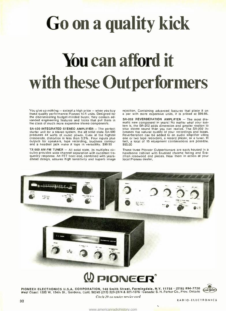
Go on a quality kick
You can afford it with these Gutperformers You give up nothing - except a high price - when you buy these quality performance Pioneer hi -fi units. Designed for the discriminating budget- minded buyer, they contain ad- vanced engineering features and looks that put them in the class of much more expensive stereo components.
SA -500 INTEGRATED STEREO AMPLIFIER - The perfect starter unit for a stereo system, the all solid state SA -500 produces 44 watts of music power. Even at the highest crescendo, distortion is less than 0.5 %. Four inputs plus outputs for speakers, tape recording, loudness contour and a headset jack make it tops in versatility. $99.95
TX -500 AM -FM TUNER - All solid state, its multiplex cir- cuitry provides wide channel separation with excellent fre- quency response. An FET front end, combined with years - ahead design, assures high sensitivity and superb image
rejection. Containing advanced features that place it on a par with more expensive units, it is priced at $99.95.
SR -202 REVERBERATION AMPLIFIER - The most dra- matic new component in years! No matter what your sys- tem is, the SR -202 adds dimension and greater realism to your stereo sound than you can realize. The SR -202 in- creases the natural quality of your recordings and tapes. Reverberation can be added to an audio amplifier using one or two tape recorders, a record player, or a tuner. In fact, a total of 15 equipment combinations are possible. $95.00
These three Pioneer Outperformers are each housed in a handsome cabinet with brushed chrome facing and Bra- zilian rosewood end pieces. Hear them in action at your local Pioneer dealer.
PIONCCn® PIONEER ELECTRONICS U.S.A. CORPORATION, 140 Smith Street, Farmingdale, N.Y. 11735 (516) 694 -7720 West Coast: 1335 W. 134th St., Gardena, Calif. 90249 (213) 323 -2374 & 321 -1076 Canada: S. H. Parker Co., Prov. Ontario
Circle 29 on reader service card
32 RADIO -ELECTRONICS
www.americanradiohistory.com

By THOMAS R. HASKETT
IN A PREVIOUS ARTICLE ('THE JFET Story," RADIO -ELECTRONICS, May 1969) you learned how the junction field -effect transistor (JFET) works, and how to use it in circuits. Now you're going to find out about the oth- er type of field -effect transistor -the MOSFET. (Its name will be ex- plained later.)
As you know, the JFET has an input impedance much like that of a
vacuum tube, and higher than that of an ordinary transistor. The MOSFET has an even higher impedance (109 ohms for the JFET, 1014 ohms for the MOSFET). Because it has such a very high impedance, the MOSFET also has very low input leakage. And it has a higher gain -bandwidth product than the JFET.
Of course, both MOSFET's and JFET's share certain advantages over other amplifying devices. As a dc amplifier, a FET has a zero tempera- ture coefficient; it doesn't drift. As a general- purpose amplifier. it has the high power gain of a vacuum tube and less noise than either tube or transis- tor. As a vhf mixer, the FET has less noise and cross -modulation than either a tube or an ordinary transistor.
Other FET features: higher fre- quency response than most ordinary transistors; nearly constant current - output characteristic (flat drain -cur- rent /drain- voltage curve); almost completely unilateral gain function excellent input -output isolation.
Chief disadvantage of the MOS- FET is that it's noisy at low frequen- cies. Thus it's poorly suited for a dc or audio preamp. Of course, like the JFET, the MOSFET cannot produce much power output.
Though expensive a few years ago, the MOSFET is now priced com- parably to conventional transistors and vacuum tubes.
Depending on physical construc- tion, an FET can operate in one of three ways -with reverse bias (or in
the depletion mode, called type A), with zero bias (in the depletion -en- hancement mode, called type B) and with forward bias (in the enhance- ment mode, called type C).
To refresh your memory, Fig. l
shows an n- channel JFET, a type -A device. (Type -A devices are usually JFET's, although a few type -A MOS- FET's have been made.) Two p -type junctions are diffused into the sides of a bar of n -type material. These junctions are connected internally to form the gate, while the ends of the bar form the drain and source. If a battery is connected to the JFET (positive terminal to the drain, nega- tive terminal to the source) much
NOVEMBER 1969
current flows from source to drain (Fig. 1 -a). Another battery connected with its negative terminal to the gate and its positive terminal to the source reverse- biases the gate. This bias volt- age establishes electric fields or de- pletion regions around the gate junc- tions. The more negative the gate, the wider the depletion regions, and the less source -to -drain current flow (Fig. 1 -b). When gate bias is great enough, drain current is almost completely pinched off or cut off. This value of gate bias is known as pinch -off volt- age. It's obvious that gate bias con- trols drain current (Fig. 1 -c). This is how an n- channel JFET operates. (A p- channel JFET is made of a bar of p -type material, with n gate junctions.
Now look at Fig. 2, which shows the operation of a type -B device. (Type -B devices are usually MOS-
through the channel (Fig. 2 -a). If the gate is biased negative with respect to the source, the channel is depleted by a field (Fig. 2 -b) just as in the JFET.
Keep in mind that as long as the JFET gate junction is reverse -biased, its impedance is high -because it draws no current from the channel. Should the JFET gate become for- ward- biased (positive with respect to the source in an n- channel type), the gate junction draws current and its impedance goes down drastically.
Fig. 2 -c shows what happens when the gate of a type -B MOSFET is forward -biased; the existing chan- nel is enhanced by the gate field, and more current flows from source to drain. As Fig. 2 -d shows, the type -B MOSFET can operate with both neg- ative and positive gate bias without
MOSFET's Part 1 -What they are. How they work
FET's, since JFET's don't operate too well in this mode.) Two junctions of n -type semiconductor material are dif- fused into and near the ends of a bar of p -type material, forming drain and source terminals. (The p -type ma- terial is called the substrate, body, hulk or hase, depending on manufac- turer. It's merely used as a base for the other terminals. The substrate is usually connected to the source, either internally or externally.) Between the drain and source terminals is diffused a channel of n -type material. Above the channel is placed a layer of oxide insulating material, and atop this layer is deposited a thin strip of metal, forming the gate terminal.
From this construction comes the device name: metal (gate elec- trode) oxide (insulator) semiconduc- tor (the bar of p -type material with n -type junctions) field -effect transis- tor, or MOSFET. Since the gate is in- sulated from the semiconductor (in- stead of being a junction, as in the JFET) the device is also called an insulated -gate field -effect transistor, or IGFET. The oxide insulator is very thin and the gate and substrate act as the plates of a capacitor.
If the drain is made positive with respect to the source, current flows
GATE
DRAIN CHANNEL DEPLETION
REGIONS
D
SOURCE
MUCH
S
LITTLE CURRENT FLOW CURRENT FLOW
a
VP OR PINCH -OFF BIAS
b
Ip
VGS c
Figs. 1 -a, b- Increased bias in type -A JFET. c- Depletion region JFET opera- tion.
33
www.americanradiohistory.com

CONDUCTING CHANNEL
GATE
METAL PLATE
INSULATOR
DRAIN
CONSTRUCTION
D PARTIALLY DEPLETED CHANNEL
SUBSTRATE
SOURCE
SOME CURRENT FLOW
o
Vp OR PINCH - OFF BIAS
ENHANCED CHANNEL
SS
SYMBOLS
LITTLE CURRENT FLOW
D
SS
ID
DEPLETION ENHANCEMENT
VGS
MUCH CURRENT FLOW
C
Fig. 2 -a -d shows increasing gate bias in type -B MOSFET and its operating curve.
Fig. 3 -a -d- Applying bias to type -C
MOSFET and the enhancement mode curve.
DRAIN NO CHANNEL
ENHANCED CHANNEL
SUBSTRATE
GATE
SOURCE
METAL PLATE
INSULATOR
NO
CURRENT FLOW CURRENT FLOW
a
VGS TH
THRESHOLD OR TURN -ON BIAS -
34
b
VGS c
drawing gate current. The device op- erates in both depletion and enhance- ment modes.
The type -B MOSFET, then, is a
normally on device. It can be turned off by reverse gate bias, or channel depletion. It can also be turned more on by forward gate bias, or channel enhancement. A hybrid, the type -B MOSFET. acts like both a vacuum tube and a conventional transistor.
Fig. 2 shows the operation of an n- channel type -B MOSFET. Its sub- strate is p -type material and the chan- nel, drain, and source terminals are n -hype material. Type -B MOSFET's are also made in p- channel versions: all materials and supply voltages arc of opposite polarities.
Type -C FET In Fig. 3 you sec the operation
of a type -C device. ( All type -C de- vices are MOSFET's.) Normally there is no channel between the drain and source terminals; make the drain posi- tive with respect to the source (in the n- channel version shown) and no cur- rent flows (Fig. 3 -a). Only when the gate is forward -biased (made positive with respect to the source, in this case) does current flow. A channel has been enhanced. or formed, by the action of the voltage field placed by
the gate between drain and source. See
Fig. 3 -b. As Fig. 3 -c shows, the type -C
MOSFET operates only when the gate is forward- biased; it's an en- hancement -mode -only device. The type -C device, then, is normally of and must be turned on by forward bias or channel enhancement. In this respect, the type -C FET operates like a bipolar transistor.
Fig. 3 illustrates operation of an n- channel type -C FET. P- channel de- vices are also made, in which semi- conductor materials and supply volt- ages are of opposite polarities.
Some MOSFET's are made with symmetrical geometry, as are most JFET's. Thus it makes no difference which end of the bar (or channel) you call the drain or source. Current flows in either direction. Fig. 4 -a shows an alternate symbol for the symmetri- cal type -B MOSFET.
Many MOSFET's, however. are nonsymmetrical. In Figs. 4 -b, c, and d you see alternate symbols for type -B nonsymmetrical MOSFET's. Note that in the symbol of Fig. 4 -d the substrate is tied internally to the source. An al- ternate symbol for a nonsymmetrical type-C MOSFET is shown in Fig. 4 -e.
All symbols in Fig. 4 represent n- channel devices. Since the symbo'.. for FET's haven't yet been standard- ized. a few manufacturers show the arrowhead pointing the other way.
Bipolar and unipolar devices Once again, to refresh your mem-
ory: Conventional transistors are now called hipolars, to distinguish them from FET's. A bipolar transistor uses both majority and minority carriers. In an npn version, for instance, elec- trons flow from emitter to collector and are the majority carriers. Holes flow the other way and are the minor- ity carriers. In a pnp version, the op- posite is truc. Bipolars are also called injection transistors, because of elec- tron -hole injection into the base.
The FET, on the other hand, is a unipolar device. It uses only majority carriers- electrons in the n- channel version. holes in the p- channel version. And because the gate of a MOSFET is insulated from the channel. neither holes nor electrons are injected into the channel.
Operating characteristics In most respects, the MOSFET
operates like the JFET. To illustrate. Fig. 5 -a shows transfer characteristic curves (drain voltage vs drain current for various gate bias values) for a
type -A MOSFET. As drain- to-source voltage is increased from zero, cur- rent flows through the channel. Chan- nel current is approximately propor-
RADIO- ELECTRON ICS
www.americanradiohistory.com

tional to drain -source voltage -up to a point. This portion of the curve is known as the ohmic region because the channel resistance is varied lin- early by the current flowing through it. It's also called the triode region be- cause the curve looks like that of a triode tube. (Near the bottom of the ohmic region of the curve, channel resistance is several megohms in a typical MOSFET.)
At the knee of the curve the cur- rent has become so great that it sets up a reverse bias along the channel which acts the same as external gate bias - it depletes the channel. The curve flat- tens out because additional increase in drain- source voltage has little effect on drain current. (The channel resis- tance has decreased to about 1000 ohms.) Since this action resembles pinch -off voltage at the gate. this por- tion of the curve is known as the pinch -off region. The channel is satu- rated with current flow, so this part of the curve is also known as the saturation region. And since the curve is flat, like that of a pentode vacuum tube, this area is also called the pen- tode region.
By operating the MOSFET in the pinch -off region, with drain -source voltage between about 6 and 18 (re- ferring to Fig. 5 -a), small changes in gate voltage produce large changes in drain current. Thus the MOSFET is useful as an amplifier.
Beyond the pinch -off region is the avalanche or breakdown region. It's similar to the breakdown region in a bipolar transistor, and if total device power dissipation is not limited to a
safe value, the MOSFET will be per- manently damaged.
A simple amplifier stage is shown in Fig. 5 -b to illustrate MOSFET oper- ation. The device is an n- channel type A operating in the depletion mode as a common -source amplifier. Input sig- nal is fed through coupling capacitor C,, to the insulated gate, which is re- turned to ground through resistor R;. This resistor is typically several meg- ohms, depending on the desired input impedance. Drain- source current flowing through resistor Rs produces a voltage drop which provides suffi- cient negative bias at the gate to op- erate the MOSFET in the middle of the pinch -off region of its transfer curve. Bypass capacitor Cs allows Rs to act as a voltage dropper for dc but not for ac.
The substrate is connected to the source. It may also be grounded. (In some devices, it is internally connected to the source.) Drain -source current through load resistor R produces a voltage drop which is taken off through coupling capacitor C(. and fed to the next stage.
NOVEMBER 1969
D OR S
a DORS D
G SS
C S
SS
D
e Fig. 4- Symbols used for MOSFET's. All devices shown are the n- channel type.
OHMIC PINCH -OFF, OR SATURATION
TRIODE OR PENTODE REGION REGION
G 20 î 15t
0
VGS
DV
-1V
- 2V
AVALANCHE OR
BREAKDOWN REGION
5 10 15 20 VDS IN VOLTS
0
b Fig. 5 -a- Type -A MOSFET transfer curves. b- Typical common -source am- plifier.
The MOSFET in Fig. 5 -b is op- erating in the common -source (gate - drive) mode. This is similar to the bipolar common -emitter (base- drive) mode and the vacuum -tube common - cathode (grid -drive) modes. The MOSFET can also be operated in the common -gate (source- drive) mode, or the common -drain (source -follower) mode. And, of course, if the device were a p- channel type, supply- voltage polarity would be reversed.
The type -B MOSFET, you'll re- call, operates in both depletion and enhancement modes. Fig. 6 -a shows drain -current /drain -voltage curves for an n- channel version of this device. They are similar to the curves of Fig. 5 -a, but notice that the gate varies
a 2 z
OHMIC PINCH -OFF, OR SATURATION
TRIODE OR PENTODE REGION : REGION
7 VGS' +4V
10 15 20
VDS IN VOLTS
o +
AVALANCHE OR
BREAKDOWN REGION
b
Fig. 6 -a- Type -B MOSFET transfer curves. b, c -Zero bias and reverse -bias.
OHMIC OR
TRIODE REGION
PINCH -OFF, SATURATION
OR PENTODE REGION
VGS , +16 V
AVALANCHE OR
BREAKDOWN REGION
2 4 6 8 10 12
VDS IN VOLTS
o
14 16 18 20
b Fig. 7 -a- Type -C MOSFET transfer curves. b- Common -source amplifier.
35
www.americanradiohistory.com

from negative to positive with respect to the source.
The circuits of two typical n -chan- nel type -B MOSFET stages are shown in Figs. 6 -b and c. At Fig. 6 -b, the stage is operated with zero bias, so the source is grounded. Sometimes a very high value of R,; is used (22 megohms, for instance) and a certain amount of gate bias is developed therefrom.
Not all type -B MOSFET's op- erate well at zero bias, however. Many work best when reverse -biased, even though the input (ac) signal drives the gate positive on alternate half - cycles. Thus the circuit of Fig. 6 -c shows several methods of such reverse bias. One system is self -bias furnished by source reistor R, and bypass as in the type -A stage. Another system
FAIRCHILD
GENERAL INSTRUMENT
MOTOROLA
RCA
GI
G2
GI
G2
GI
D
G2
S a SS
36
b ss
D
S C SS
SS
G2 o o oGI
ó
Ss
S SS
o o o D
o
S
o
o
SS
o jG
Fig. 8 -Base ter- minals above for MOSFET's are the configurations used by some manufacturers.
Fig. 9 -Dual -gate or tetrode MOS- FET symbols are illustrated on the left. All are type -B.
omits source components, using gate resistors Rr, and Re., as a voltage divider across the supply. This is known as constant -current biasing, and useful because it allows the gate to go both positive and negative.
Even if zero bias is desired, the MOSFET gate must not be allowed to float -it must have a dc return to ground. Otherwise, the gate may build up a high potential from stray coupling. Such a high potential can puncture the insulator between gate and channel, destroying the device.
A p- channel stage, of course, would be the same except for supply - polarity reversal.
Curves for an n- channel type -C (enhancement -only) MOSFET are shown in Fig. 7 -a; they look more like those of a bipolar transistor than of a vacuum tube. This is not surprising, as the enhancement -type MOSFET is normally off and must be turned on, just like a bipolar.
Typical biasing of a type -C MOS- FET is shown in Fig. 7 -b. Since only forward biasing is used, the source - resistor scheme cannot be used, and bias is usually obtained from a divider across the supply. Sometimes only a single resistor- R,;, -is used. A p- channel version would, of course, op- erate the same, but with reversed sup- ply polarity.
In the previous article, differences between n- and p- channel JFET's were mentioned. These differences also ap- ply to MOSFET's. The mobility of electrons, you will recall, is greater than that of holes. Since electrons are the majority carriers (which are all FET's use) in n- channel devices, they are better than their p- channel coun- terparts in several respects. N's have more gain (for a given input capaci- tance) than p's; they also have lower on resistance and lower noise figures.
Dual -gate MOSFET's You learned about dual -gate or
tetrode JFET's in the previous article. MOSFET's are also available with two gates, and they are also useful as mixers, converters and in agc applica- tions. Some are also used as stereo FM and color TV demodulators -and they would probably work well as product detectors in SSB receivers. Three symbols for dual -gate MOS- FET's are shown in Fig. 9. All are nonsymmetrical type -B devices, and in each the substrate is connected in- ternally to the source.
Handling precautions Because the MOSFET gate has
such high impedance, it's extremely sensitive to static voltages that may be discharged through it during handling and installation. The oxide insulator
between gate and channel may easily be punctured by such a static voltage. It's common for the human body to build up a static charge of thousands of volts by walking across a rug, for instance. Though only a small current may flow when this charge is dis- charged to ground, the MOSFET's high impedance makes it so sensitive that the oxide insulator may be punc- tured. This causes permanent damage to the device.
To avoid damage to a MOSFET, you should observe three precautions while handling them.
1. Retain the shorting ring ()- wire around the MOSFET leads which is supplied with the device. If no short- ing ring is supplied, the manufacturer usually tapes the leads together. Don't remove or unshort the leads until the device has been soldered or otherwise installed in a circuit. (I'll explain an exception to this rule later.)
2. Be sure the power is off be- fore installing or replacing a MOS- FET.
3. Ground yourself and the tip of the soldering iron or gun while sol- dering a MOSFET in a circuit. One way is to place the circuit on a ground- ed metal plate, and rest your elbows on that sheet during installation. Use a clip lead from the soldering tip to the sheet.
In an attempt to protect the gate from accidental static -voltage dam- age, some manufacturers fabricate MOSFET's with integral gate- protec- tion networks. That covers the theory portion of this series. Next month we'll present some practical construction projects using low -cost MOSFET's, and show where the various types are best used.
(To BE CONTINUED)
"I'm no engineer, but physics department just lost a patent."
331-000-
I think our
RADIO -ELECTRON ICS
www.americanradiohistory.com

NEW R -E EXCLUSIVE
6HS8 noise- canceling sync /agc stage
agc section
Kwik- FixTM picture and waveform charts by Forest H. Belt & Associates
SCREEN SYMPTOMS AS GUIDES
SYMPTOM PIC DESCRIPTION
Agc overload, no sync, sound buzz
Weak picture, sync okay
Weak picture, sync poor
Weak picture, bending and flagwaving
Whiteout, sound remains
Whiteout, no sound
Agc overload, sync fairly normal, sound buzz
VOLTAGE
cathode -pin -1
screen -pin -2
G1-pin-7
G1-pin-7 -plate-pin-3
G3-pin-6
G1-pin-7
not .much help
screen -pin -2
G3 -pin -6
NOTES: (lye this guide to help you find which key voltage or waveform to check first. Study the screen and the action of the Agc and Noise Gate controls. Most helpful clues to the fault are found at the key test points indicated.
NOVEMBER 1969
WHERE TO CHECK FIRST
WAVEFORM
WF1 WF2
WF2
WF1
not much help
WF2
WF1 WF3
WF1
PART
R8 C5
R6
R7
C2
R1
R2
R7
R4 ard m OSt
ot" iers
R2 R9 R10
an Easy Read'" feature by FOREST H. BELT & Associates 1969
Make voltage or waveform checks as indicated for screen symptoms. Use the VOLTAGE GUIDE and WAVEFORM GUIDE to analyze results. For a quick check, test or substitute the parts listed ces the most likely cause of the symptoms.
37
www.americanradiohistory.com

THE CIRCUITS THIS KEYED AGC STAGE IS POPULAR, ESPECIALLY IN
color sets. Tube has special twin -pentode construction, with some elements common to both sides -cancels noise for both sync separation and automatic gain con- trol action. This issue of Kwiek-FixTM, number 6, covers keyed age; next issue, number 7, covers other half of tube -sync separator.
Grids 1 and 2 and cathode are common to both sections, terminated in pins 7, 2. and 1, respectively. Agc section has its own separate G3 and plate, pins 6 and 3 (pins 8 and 9 are plate and grid 3 for sync separator section). Grid 1 is noise- canceling grid for both sections. Grid 2 is screen grid for both; constant positive voltage there affects general conditions of con- duction for entire tube.
SIGNAL BEHAVIOR Video- and -sync signal from video amplifier is ap-
plied through compensating network Rl -C1 -R4 to age grid (pin 6). Sync pulses in WFI. which are positive - going, exercise strong control over conduction in this section of tube. when tube can conduct. Thus, amplitude of WF1 sync pulses determines amount of conduction.
At same time. video signal with negative -going sync is applied to noise -cancelling grid at pin 7. Bias is enough on grid -pin -7 that any signal of higher amplitude than sync pulses (such as noise) drives tube 'way into cutoff. No noise pulse can therefore be amplified, even if it reaches grid- pin -9, because same noise impulse (but in opposite polarity) is cutting this vacuum tube off at grid - pin-7.
Meanwhile, high -amplitude keying pulse from fly- back is applied to plate -pin -3 of tube through C3. Pulse is positive -going, acts as short -duration plate voltage for tube. Is large enough in value to make tube conduct, provided that, at same time. positive sync pulse in WFI is present on grid -pin -6 and no noise in WF2 is cutting off tube at grid- pin -7. Amount of plate current is de- termined mainly by strength of positive -going sync pulse on grid -pin -6.
Noise or any other signal disturbance between sync pulses can't affect age voltage developed, because keying assures no plate voltage except during retrace (and horizontal sync pulse) time.
Capacitor C4 decouples screen grid from B -plus. us- ing cathode- bypass capacitor C5 as an easy signal path to ground.
FROM VIDEO AMPL
VARIES WITH R7 SETTING,.----- -
35-50V
38
RI 68K
FROM HORIZ FLYBACK
DC DISTRIBUTION Plate voltage for age section of 6HS8 is pulse from
flyback transformer (from horizontal output plate in some receivers). Exists only during sweep retrace in yoke. Result: tube acts as grid- controlled rectifier of keying pulse. Steady negative dc voltage develops on plate -pin -3, value controlled by amplitude of sync pulses in video- and -sync signal on grid- pin -6. Output decoupling network (not shown) distributes age voltage to rf and i.f. stages, after filtering it. There, it controls gain, com- pensating for variations in signal strength.
Bias between cathode and grid 1 of tube is set by controls R7 and R8. Noise gate sets level of operation for G I. Control is set for dc voltage level just below tips of incoming sync pulses. so pulses won't quite over- come dc voltage. Agc control R8 adjusts cathode voltage -thus sets grid -cathode bias. Determines conduction for any particular amplitude of signal applied to grid 3
(pin 6). That. in turn. determines level of age voltage. Resistor R9 from cathode -pin -1 to plate -pin -3 ap-
plies slight positive bucking voltage to delay age, and is input load for keying pulse. Constant screen voltage is applied from 250 -volt line by R 10.
QUICK TROUBLESHOOTING Overloading in i.f. and rf stages of receiver, caused
by too much or too little age voltage, can confuse troubleshooting attempts. Leaves no proper video to operate age stage. First step, always, is to clamp age at whatever value lets video through the screen.
Don't apply too much clamp voltage. Just clip variable dc bias supply to i.f. age line and turn up voltage until picture is visible. May be out of sync, but that's okay. Leave age and noise gate set at center of rotation.
Then, with video on screen, go ahead with wave- form and dc voltage checks. Use scope first. Plenty of faults cause very little dc change, yet warp waveforms noticeably. Check output of video amplifier before an- alyzing WFI; it is source for that waveform. Likewise, check video detector output before condemning WF2. NOTE: If waveform display is shaky or jittery on scope, adjust receiver hold controls for as steady a TV picture as you can get.
Also, see next Kwik- Fix", number 7, which is companion to this one -shows sync -separator side of stage. ( WA VEFORM CHARTS ON NEXT THREE PAGES) R -E
C3 , 470DF -20V
C2
FROM DETECTOR
cis", 01 R4 `/
270K V
R2 100K
I25V
K--
3
R5 33
R3 MEG I5K
7 38V
R6 1 '
330K AG R8
10K
1/2 6HS8
87 7.5 MEG
TO I F AND RF AGC NETWORKS
R9 I MEG
C4
NOISE
1
GATE
125V
« C5 I0µ F
150V VARIES WITH R8 SETTING,
250V 35-5OV
RIO I5K
iital rfteNt R
RADIO-ELECTRONICS
www.americanradiohistory.com

DC VOLTAGES AS GUIDES
Voltage change to zero very low low slightly low slightly high high
cathode-pin -1 Normal 40 V Varies from 35 to 50 volts with setting of R8. Develops as result of average plate con- duction in tube.
R10 open C5 short
R7 open R10 high C2 leaky C5 leaky
C2 open C4 leaky
R8 open R10 low C2 open
screen -pin -2 Normal 120 V Is applied through R10 from 250 -volt line.
R10 open C4 shorted
C4 shorted C5 shorted
R10 high C4 leaky C5 leaky
C4 leaky R6 open C2 open
R5 low R7 open R8 open R10 low C2 leaky
plate -pin -3 Normal -15 V to -30 V Depends on how much video /sync reaches grid -pin -6. 1 -f agc line should be clamped for testing.
R2 open R3 low R8 open' R9 low '
R10 open R10 low' C3 open ' C4 leaky
R1 open R2 open R3 low
R1 high R7 open C2 open
R5 low R6 open
R2 low R3 open, high R10 high C2 leaky C5 leaky C5 shorted
G3 -pin -6 Normal 30 V
Varies with amplitude of input video signal. Developed by grid -leak action across R5.
R1 open R2 open R3 low R10 high C2 leaky C5 leaky
R6 open R7 open
R8 open C2 open
R2 low R3 open
G1 -pin -7 Normal 38 V
Varies from 35 to 50 volts with setting of R7. Comes through R7 from 125 -volt ilne.
' Voltage goes positive
R6 open R7 open R10 open
R6 high R5 shorted R10 high C2 leaky C5 leaky
C2 open C4 leaky R8 open R10 open
NOTES: Use this guide to help you pinpoint the faulty part. BE VERY SURE to clamp i -f agc line as described in text; indications in this chart are valid only under those conditions. Measure each of the five key voltages with a vieni.
For each, move across to the column that describes the change you find. Finally, notice which parts are repeated in the combination of changes you find. Test those parts individually for the fault described.
WAVEFORMS AS GUIDES
WF1 Normal 15 V p -p
Taken at 03- pin -6, this is high -amplitude signal containing video and positive -going sync
pulses. Has been amplified and inverted by video amplifier before being applied to
input network R1- C1 -R4. Effect of compensating network is to sharpen leading edges of
video signal -result of frequency peaking. Amplitude of sync pulses is what determines
how much dc agc voltage is developed at plate -pin -3 and fed to i.f. and rf stages of
receiver.
NOVEMBER 1969 39
www.americanradiohistory.com

1 !4
.+rw "¡mow ".,4
WAVEFORMS AS GUIDES
V p-p low
R3 low C5 leaky
V p -p high
R1 open R1 high
V p -p zero
R2 v. low C2 leaky
10 V p-p
R1 low
3 V p-p
R1 open
6 V p-p
R2 low
10 V p-p
R3 high
10 V p-p
R5 low
3.5 V p-p
R7 open
10 V p-p
R8 open
7Vpp
Cl open
2 V p-p
C2 leaky
12 V p-p
C3 open
12 V p p
C5 open
2 V p-p
C5 leaky
15 V p -p
C7 open
WF2 Normal 0.6 V p -p Taken at G1- pin -7, noise -canceling grid, this is video -and -sync signal directly from video detector. Sync pulses normally point negative. No compensating network at input, just dc- blocking capacitor Cl. Note trailing edge is sharp, rather than leading edge as in WF1. This signal doesn't affect operation of tube much unless there is noise accompanying signal. In that case, noise pulse blocks conduction momentarily to keep noise from appearing in agc output (which is dc at plate -pin -3).
R1 low R2 low C2 open
R8 open R9 low C4 leaky C5 open
C2 open
2 V p -p
R1 open
0.4 V p-p
R2 low
e.0.1.
á
0.5 V pp
R3 high
2.5 V p-p
R5 low
2 V p-p
R7 open
3 V p p
R8 open
4 V p-p
R9 low
0.4 V p -p
R10 open
0.4 V p -p
C2 open
2 V p -p
C2 leaky
0.3 V p -p
C3 open
2 V p p
C5 open
0.6 V p-p
C7 open
2 V p-p
C7 shorted
0.6 V p -p
C5 leaky
40 RADI 0-ELECTRON ICS
www.americanradiohistory.com

WAVEFORMS AS GUIDES
WF3 Normal 200 V p -p
Taken at plate -pin -3. Don't misconstrue this as output pulse, however. This waveform is high- amplitude, short -duration, positive plate voltage for tube. When this voltage is ap- plied to plate at time that coincides with positive sync pulse at G3- pin -6, tube can con- duct. If WF3 is missing or inverted, check wiring from C3 all way back to flyback trans-
..... former, or to whatever source supplies keying pulse.
V p -p low
C3 open
V p -p high V p -p zero
C3 open C9 short
12 E 0.4 V p -p
C3 open
2 V p -p
R9 low
NOTES: With the direct probe of the scope, check the three key Use titis guide and the Voltages Guide to help you pin waveforms. The scope should be set at H or about 5
down fault possibilities. kHz, to show three cycles of waveform. ALWAYS clamp the i -f agc line at whatever voltage Note amplitude. If it's low or high, check parts under lets video reach the TV screen, even if .sync remains those descriptions. poor. All waveform symptoms shown in this chart are Note waveshape. If there's a change from normal, check taken under those conditions (see text). the parts indicated.
AUTOMATIC TINT CONTROL FOR COLOR TV grees at the chroma amplifier. The phase of the red correc- tion voltage at this point is
343 degrees -leading the burst by 17 degrees.
When fleshtones shift from 57 degrees toward yel- low, the correction signal produced at 103 degrees com- bines vectorially with the original chroma signal to produce a 57- degree resultant. (This assumes that the ATC
switch is at FULL and the chroma error doesn't exceed 30 degrees.) When the flesh- tone shifts toward red, the 343 -degree correction signal adds to the chroma signal to produce a 57- degree resultant signal.
When the ATC switch is
set at FULL, all colors between a yellowish- orange and a
bright red are combined to produce a 57- degree orange in the fleshtone orange. Thus, a vectorscope pattern of a
modulated color bar will show variations in the area between zero and 90 degrees, depend- ing on the position of the ATC
switch. When it is OFF, pulses
NOVEMBER 1969
(continued from page 4)
representing ten color bars will appear 30 degrees apart; starting from the burst at zero degrees.
The first petal or pulse represents the yellowish - orange bar at 30 degrees; the second represents the orange bar at 60 degrees and the third is a bright red bar at 90 degrees. When the switch is in the PARTIAL position, the 90- degree pulse moves counter- clockwise to around 78 de- grees and the 30- degree pulse moves clockwise to about 45
degrees. Throwing the switch to FULL, causes the first three petals to overlap at 57 degrees and the fourth petal moves around to about 87 degrees. Thus, with full atc correction. all colors transmitted with phase angles between 30 and 90 degrees will reproduce as
57 degree fleshtones. Natu- rally. this correction causes
shifts in some background colors between yellowish - orange and red but, generally, this is not as easy to detect nor as annoying to the viewer as an equal phase error in
fleshtones without atc correc- tion.
(A few weeks with the Magnavox T940 chassis with atc proved that automatic tint control does have disad- vantages under some condi- tions. One evening my wife called to me, "Come and see the invisible singer on TV." All I could see was an almost solid orange screen with a
pair of eyes, lips, the faint outline of a nose, gloved
hands and shoes. My heart kicked up as it occurred to me that the picture tube had failed. When I regained my composure, I flipped the atc switch from FULL to OFF.
Now, we could see a beautiful honey blonde in a light orange dress against an orange -red background. The atc circuit had converted nearly all colors in the scene to fleshtone -orange so the gal was nearly invisible.) R -E
AIRCRAFT RADIO
OH-OH
c
c
41
www.americanradiohistory.com

FOR MODEL RR
Electronic
Throttle Solid -state features include dual variable -speed
and inertia controls, automatic -latching tripout and panic button
by HENRY J. MIERLAK
MODEL RAILROADING RECEIVED A
mild "shot in the arm" with the intro- duction of N gauge. About half the size of the popular HO gauge, com- plex N -gauge layouts occupy much less space than any other gauge model railroad. But complex layouts (any- thing greater than a single -track cir- cuit) fall flat in performance and en- joyment unless versatile control of train traffic can be achieved.
The dual throttle unit described here will give the hobbyist stability and versatility for a two -circuit layout with these features:
Two 0 -14 -volt variable -speed out- puts regulated up to 1 amp each. Ac accessory output (20 volts). Variable dc output for lighting. Variable inertia control. Trains accelerate and brake at a select- able rate. Automatic- latching tripout with indicator to remove all track cir- cuit power when an overload oc- curs. Panic button to stop all track action in case of a collision course requiring quick action. If some of the features are not
desirable, a simpler and more eco- nomical throttle can be built. Simpli- fying the throttle unit will be de- scribed later and is accomplished by deleting sections of the unit. Before we start drilling and soldering, let's
42
look at the circuit of the electronic throttle by sections (see Fig. 1).
Power -supply section Transformer T1 supplies two
rectifier systems: one full -wave for the track circuits and one half -wave for the lighting circuit. The full -wave dc line has a 750 -µF filter (C1 and C2) as the minimum value for good speed regulation and stable operation of the tripout circuit. The lighting circuit receives unfiltered half -wave dc since regulation is not required here. The pilot light and ac accessory outputs are tapped from a 20 -volt side of the transformer secondary.
The filtered dc line is fed to two series- control transistors (Q5 and Q8) through the tripout relay contacts, and to the reference -voltage source (D4 and Q2). Darlington amplifiers permit use of low values of control current from the control section.
Control section Zener diode D4 and R5 hold
Q2's emitter at 17 volts, and Q2 of- fers isolation and current gain be- tween this Zener and the control transistors. Capacitor C3 is used for RFI (rf interference) suppression. Transistors Q9 and Q l0 are controlled directly from the wiper of R7. The lighting output voltage is about 11/2
volts less than the wiper arm value of R7 due to base -emitter voltage drops. Up to ten 6 -volt miniature lamps can
be used to light up your model railroad layout.
Track circuits 1 and 2 are iden- tical, so only the description of track I's circuit is necessary. When S3 is in its shown position (INERTIA OFF), Q3's base is tied to the reference volt- age source through R9. The track voltage is determined by the settings of R8 and R13, and it follows the speed control position as in any con- ventional throttle unit. When S3 is in the INERTIA ON position, R8, R9, RIO and C4 set up an RC delay for any change in R8's wiper position, thus the inertia or delayed- action ef- fect. Pot R 10 has a delay range of about 7 to 30 seconds for completion of the train's gradual response to the resetting of R8.
Bleed pot R13 maintains a dc potential on the tracks, and is set to the point where the engine(s) is just about to move. This gives the speed pots control over the full range of ro- tation, and train movement therefore begins during the first few degrees of rotation of the speed pots.
Tripout section This section offers protection for
the unit and warns of trouble on the tracks. When either track circuit draws more than 1 amp for any rea- son, the relay (RYI) activates and removes all dc from the two series pass transistors (Q5 and Q8). Relay RY1 is latched through its contacts;
RADIO -ELECTRONICS
www.americanradiohistory.com

D5 IN400I Î
D6 I N400I ] R2
5S2_ 2CW
I17V AC
T
DI
AI5F 2oV H + u
OV
°-IOV
D2
AI5F
4
3
327 LM I
POWER
20V
D3
1N4001 =
Use chassis as heat sink
19
PANIC 152
BUTTON 0
200
Rl C2 5d1
500/ 20W 50V +¡
--- C I T 250/50V
C
o
N.0
R5
C3 .005
RYI 24V DC
Q2* 2N696 ,
D41
IN4746
R3
G-3
2N695
e,. 2N696
R4 5.6K
01* 2N2I481
010
327 LM2 SHORT
R6 R8 1.5K 5K
R7 1K
11
R'9 5 18K
SPEED
RI6 2 2K
Q5* 2N3055 DIRECTION
S4 / 13
o o
06 214696
e®6 Q7 S5 o 0 17 l0 O -o
9 ? I TRACK 2 I
o
14
TRACK 1
DIRECTION
2N3055
2N596
R15 2 2K
0 S3
INERTIA
OFF R11 181(
6
SPEED 2
LIGHTS
C4- ,.C5 200/I5V 200/35V
913
i - 7 1K
RIO / ' RIO BLEED
20K ,
20K
12 ACCEL /BRAKE o
RI2 5K
18
AC ACCES
LIGHTS
010* 2N3055
PARTS LIST Capacitors C1- 250 -µF, 50V, electrolytic C2-500-1(F, 50V, electrolytic C3- 0.005 -RF, 100V ceramic or mylar C4, C5- 200 -pF, 15V, electrolytic All resistors 10% or better R1, R2 -5 -ohm, 20 -watt wirewound R3, R5- 1000 -ohm. 1/2W R4 -5600 -ohm, '/2W R6 -1500 -ohm, 1i2W R7, R13 -1000 -ohm, 2 or 4 -watt, linear wire -
wound potentiometer R8, R12- 5000 -ohm, 2 or 4 -watt, linear wire.
wound potentiometer R9, R11- 18,000 -ohm, 1/,A/ R10- 20,000 -ohm, dual linear poteniometer R14, R15, R16 -2200 -ohm, 1/2W Semiconductors Dl, D2 -50 PIV, 3A, silicon diode (G.E. A15F
or equal) D3, D5, 06-50 PIV, lA, silicon diode (1N-
4001 or equal) D4 -18 -volt, 1 -watt, 10% Zener diode (1N4746
or equal) Q1- 2N2148 transistor Q2, Q3, Q4, Q6. Q7, Q9 -2N696 transistor Q5, Q8, Q10- 2N3055 transistor Other parts T1-40 -volt center tapped with 10 -volt tap
power transformer (Triad types F -92A or R -204 A)
RYI -24 -volt, dpdt- contact relay (P &B type KA11DY or equal)
S1 -spst toggle switch S2- momentary- contact pushbutton switch S3. S4, S5 -dpdt toggle switch MISC -prepunched board, terminal strip, TO5
clip -on heat sink, knobs, cable, chassis
AC ACCES
Q Use Fig. 1 above to wire an electronic throttle like the author's or any of the variations described in the text. Numbered circles above are connections to a control panel. Photo shows U- chassis and L subchassis used in this version.
NOVEMBER 1969 13
www.americanradiohistory.com

the ac power switch must be switched off and back on to unlatch it. When pressed, PANIC BUTTON S2 simply activates RY1. Transistor Ql is nor- mally off and R3 and R4 are selected to turn Ql and RY1 on when either R1 or R2 drops 5 volts or more due to currents of I amp or greater. Lamp LM2 visually indicates the overload or short condition of the tracks.
Construction tips Use whatever component layout
your railroad calls for. I housed the controls and switches on a panel and the remaining components in a deep U chassis. A 20- conductor cable was used between the panel and chassis. Numbered circles on the conductors in Fig. 1 show where I used a cable between the two subassemblies. All small components (except C3 and
C4) were mounted in the chassis. Parts T1, RY1, D1 and D2 are mounted on an L subchassis. A screw -type barrier strip was used for the output terminals. Transistors Q1, Q5, Q8 and Q10 are TO3 -style de- vices, and since their maximum dissi- pation ratings far exceed circuit dis- sipations, the chassis was used as a suitable heat sink. Use silicone com- pound and a chassis 1/16 inch or thicker. Dry transfer letters were used for labeling the functions and a brush coating of clear nailpolish protects the labels.
Design considerations Wirewound controls should be
used for R7, R8, Rl2 and R13, and 2N3055's should be used for Q5, Q8 and Q10. The rest of the components are not critical and appropriate sub-
Behind author's control panel. A 20- conductor cable ties controls to the chassis.
stitutions can be made. Component layout is not critical, and the alumi- num -plate heat sink for the four pow- er transistors should be at least 8x4x1/16 inches. A chassis side may be used for heat sinking. A push -on heat radiator for Q2 is required.
If regulation of the lighting out- put is desired, add a 500 -p.F, 25 -V electrolytic capacitor between Q 10's collector and ground. If an adjustable tripout is desired, add a 5000 -ohm pot between R3 and R4 and connect the wiper to Q1's base. Also change R4 to a 1000 -ohm resistor. You can then set the tripout point to your needs. Delay time of the inertia fea- ture can be increased or decreased by changing the values of C4 and C5.
By deleting portions of the unit, a simpler and cheaper throttle unit can be built. If the panic button and tripout feature are not desired, RYI, LM2, S2, Q1, Rl, R2, R3, R4, D5 and D6 can be deleted. Just return the collectors of Q2, Q5 and Q8 to the positive ends of Cl and C2. To elimi- nate the inertia features, omit R9, RIO, RI I , C4, C5 and S3. Connect R8's wiper directly to Q3's base, and R12's wiper to Q6's base. To omit the lighting circuit, remove D3, R6, R7, R14, Q9 and Q10. A tapped trans- former would not be a requirement for the unit now. R -E
TOOLS FOR ELECTRONICS by TOM HASKETT
Hand tools are vital to working in electronics. In the past two months we have presented a complete picture of how and when to use what kind of pliers. This month we continue our series with a complete rundown on screwdrivers. In the months to come many other kinds of tools, including wrenches, screwdrivers, alignment tool, power tools, etc. Each section will become a handy, practical addition to your R -E Reference Manual.
For those of you who have vainly tried to assemble the first two installments of this series, we offer our apologies. Our printer, in both issues, carefully turned the backup pages up- side down, making this an impossible task. As soon as we have ironed out a method for providing you with corrected pages we'll let you know.
MAKE AN R -E REFERENCE MANUAL
If you wish you can purchase a special hardcover binder to keep your Reference Manual pages together. It has a dark blue fabric cover and is gold stamped Radio -Electronics Ref-
erence Manual. The cost is $1.00, postpaid. Order from N. Estrada, 17 Slate Lane, South
Hauppauge, N. Y.
44 RADIO -ELECTRONICS
www.americanradiohistory.com

N b4 (Q Ú C C Ç R o CO E C Y a)
, ti a)
co
a_ ,Ç d
h[t L co Ñ LZ ~ M L C c [ U O
Vi C
C Ñ a.
o d N
-- \ O N c a
Ian ',D LC) i 73 -
a) fQ
X c .°i > N cQ 'i a)
-c) Y C S O U
Ñ- 115 p.0 ca o) us 3
:1- o E --,..."1-
N E(-o (Q d
N U cQ (a
ai o o t c o- L.-, C 13 +U+ a
----. o (Q +="n vi
L V _E
O
U 3 C3 Ç > O
0 0 O
- Ñ SN CU D o1-
Ts) +L- (Q in
o
CILS
7 y .... :dco :- C p k°,3
._
co ., ., C a) G a L: .: , .-.
o ?S. G 4.: P. C Caw ° a) tt .. Q
4,..G ,41
.
CI) I ÿ 7±-.. E ^ H i y G w ù ^ ó ó ó
3 L g Ó Ñ - a)
U N
N
-0 4:71
N O c O N o O O
a_
- C co ° c O bA N CO (Q X O C -C w 4-
o
C
+J +r o +- i C O -O o (Q . _ CD 73 0 0 - a) N o C O o p O N C - N a) 3 a o> N ß C a)
N E C ' 'N + (6 .i Q
o " o E *' " o O >' -° +J o 0 0 Q O O(Oj) O O T oC C L 2 a) >+ ( Nn U o gp a O Q3lI
vi (Q O -+
V RS
i.p ° co Ç N
C 7 CO 7 E O N ß O (6 i O.
V L > N
(Q
< T al>
T C R ¿ ó Ñ o á L R m0 O i t o
+L, O .0 -c) ß Ó L m +L 3 U ÿ
L o +'' Y o N (Q a C Ú j N L a (Q o i ++ a) .i ` .Q E
°O N 3 _ O
O N N L-+ Ñ -a (6 0 0 .a_ c 7+J _ ' i o o a) v- C O. r 0 3 >> cñ Ú
N o C Ñ U a0- rr 0 0 o a-. O } 3 t cu Ó j >. E a ó .> N N N a 3 Ú
ß 0- - (Q co o +
en Ñ o e o E °- e ó +D ceQ
Q e m N U Ñ- . N + O o Y U
E L w N 3 a3 4-, L.- co E I-- ) ' +L. C ` a_ L 0 O i(Q o O N L N N v- N o 3
o U U L Ñ o N - (Q O Ñ> L -- >, N> o o Q cQ Cl.) E(Q ,r 4-' c.) U co a) 'C a ° L i l,yJ ú N-o N (Q C +J
a) o a) o N C a s N a) i QD a. o U.
a) w Ú N Ó N.N O cQ Ç +' j O E o s L Z f° CU
o p I- cQ E w c(a I ' N °) H a > E a o ao p s c 3o
L ac0i 3' c m
6. ó-oa ÿ voi 3 Ñ } cv a_ i +- a_ C o L o 0 0.c 'a_ c L + 0 3 c Q A U o O o 3 a. C Y +L,,, R L to N E O
°' ó m° 3 °° ó f° .0 .0 F- o o i m o° E
C o o+L- o cQ o O N (Q (Q O L L b0 3
+' y m ° E 0 aá o- w>, ~ L o ca ó.E
v E N i C ívi) -0>$
rr .= j 0 3 p OA p a 0
o Q
> co
> m o --
Q + ° a ó- o ... 3a y O-C p L L +' co a) a) C -C co L `° E 3° 3 I Y i... I-
á) É s ó a' H w o H e L -a a) i i eo +, z E E > N (U
1.
N C c U C L U L C C a_ a_ Oi a N too O cQ N co F- N a y O a) (Q O O v`- C 10 (Q
C d¡ V) 7
F a °, ..,
L °_°
v Ó a c o
bA
7 . C -iá _ DL C O (Q i ..c
o N -0 as
o :,...5
.-+ N
i ap a) a)
C L O a--
U Cp Ñ N ^,-.,;: ÿ L r Y
-1-0 i G Cl.) c U ..tr, L .Q
. +j - (Q
C E
O o 4 y,,,
p o y_,
www.americanradiohistory.com

> .v) m .c i U_
-a c > .,c ó tv 3
C +' V) Cl.) (0 (1)
Q - 4-,
> +L+ a] Q C
7 6 . N Ñ C > .Q c c c(s ca
Q V) ß >
Q L CO
U a) i b0:0 (6
U l.L
.0-... L V)
U L a) U
C..) f.) bi) Ñ d C ¿i N_
U. i .. i -- 3 ÿ -0 3 N 'y>-, m
V) - N Ñ N Q a.. C a) C
a) a) > O
7:3 C Q -o É
J w C
OU
á) v c Q42., O co -44 co _c
s
V)
1
N N á Óf Z, i a O ' j ++
U .0 _ i CD a_ - - -. a a) O
a C Ó - Q Ñ
(a
C -.. O U v) m U _ ..
CO fß as 4-+
T ß d a)_
_ ' d Y 3 c cv . J Q á uUi _ >, - a) ' 3 4- E a)
a) = I 4C O i L (ß a)
cl + E ° ` 4-' -á) -f.
74 ' > (6 Oo
. 0 a) .
ti = .i L V)
0 Ú 3 U
LE .., N 3 ...4- V)
i tA O
..
z..-. O U) Ç n M
.9. .V V) , O (4 ÿ O it co t Ó p o 4-i >, E
O
i L O = to y-' in 3
CD
4= 4-4 U ......CL
Ó (U
Ç -L i O
y-
rt > h- 0,6 a) O U L Z '>
z á E Eo
0 = O 3 4- N N
18 O i
C Ñ vU)
Z cß cu N a- U a) Q o6
E N _ cc O 1:3 Ç C , +J (ß
vì o 3
Ó U U V) a) Ñ N
$.-
> Q O CO E -o a- N L 2 v) v) ++ (6 Q > p 3 N = i
> la- c U co
..0
a) 3 0 .c -O ca
-0 a) as a- v) (6 Ñ a 0.2s c E >,Ncc+, a) .1-, CO o o ^ c
co a) -O 'Kr c V .c
V a) C D -CO
Ñ o a)
bU > L_ 7
'47_ C a) >
'0 7 i v O_
CO CD i N Ó O co I-
tUn > lL N Z
0
www.americanradiohistory.com

o c ±- a o 40 4 O c a) a) ÿ,.i *' 3 + : [r Ñ 2 p Ñ U 4C C
s. o O
o N 3 . y íG. Ç ^
v ++ CO a) N p b0 C
,.F.'.
0 'ï O,N O ÿ^ C
O C
V) ó -C- bn m L ó
N C U O y O a O 0 O
Ç ,Ç; v.2
(6 y T C N.Q l() ......OL -5 w _ L o é d CD I'D C L 7 0 . tÀ 7 i 0 0 . . . - . . i . p út
cç0) cEv °) 3
oo CG ó
> N L y p c0 cß CO O C r .0 0 3 y L a
ó) é '-.
. O N n ca . r a. -p U `°
,--4 b0 N í C9 CO N L it i v C L N b0
Li- Q) a ó S),-, -C - O X-
4-0 `
07,
L t -0 O b0+..: C w +. , co ca
bp fß
c LT_ O
.5 CC) ' __ a L L T y , O U.? i CO o CC .. ÿ r CO
^ -c 3 3 c ,
6 Si' ` b0 ...V0.s 7, ).- ,_ C Li: a)
' ..5 u ,, c C . > x O O -0 i ; }i
ti 2 2 I z c
U ß
as v) .r._-
U " . :d y ÿ w C'' C N
C y .`ti fx 7Oi . : . 0 i a U <
K O O R. ""0 01 *--- d a c° Ñ is CL)
3 C L N a) O +J +. d
O N ""' L.-
U) V X fd L _Ú CL)
O CO i L
Ñó cß
o 3 y 4-, c á
C O Ñ ca L O -+ M
E L X
a, y y a) N > i a > L as L > 3 cß
10 >+ s` fß aY N
C c0 -0 L 4.= E- Ñ a . o ó. +.,
O y a) on >, E i L E T.L- o Ú 'X ;-
a) y as o
O C 03
N a a) i- O O b0 N a) y
+; Ñ ß L C .0 +L.+ C
7 Ú Q.Ñ Ç Ú
o a co Ú Q O o
a) O . a) U T > i N f6 N = a . o .E <
M N
V) -0 a ,j.)
> O
C ++ N > O
O. ï p i a. C U
3 ß
U O
C > N p O 03 T as
N L O N Q > ^ To y
cCs
co ai 0 Da o
_o 7:3 Ó C co - -a Jo N Ñ c a c y o .r o Ñ C T y Ç Ó y t 2 7 C O
4-, O
N co U E co
cis Ç N L 73 O i L C O a) y cp Vr i
a) > N L as L ß 3 ? F-
0 CO U N >i a) i a) ,--c
>a, > U U +' Ç b0 N
C 'tD
0 n co
E o- oÓ a) N .0 +J y a ß C C y Ñ .ä L O O co Vj y Ñ E U a O Q = O
O ..
V) (ñ i y 7 4-5 ß > O L -0
40 a y
b0 O
% C O vì O
T L N i L O c L vì a) a, L a) s.-
5 t'. 7 L U N a) y i U O
L N c 5. O a),0(- E
C a p °
O c°
r p 0 , N? -C) i c 4? i ..- + L + cß +. p c0 N -0 a) ü
c á o ii ai N Ñ E y y°-o U E CO L o. U a) -o C4 i' -0 i 7 7 7 .-. y O fß y N C cv a)
L Q T a) L C H+J p co -p
). á `° a m ó a L E ó X C} s co
ÿ i U N +' y byp p E ` cá as L vOi uNi N O L L
as O > Y a) f6 O Ú N ,, i) \ X N Ñ" i
`ri ÿ°' ó o N C N bn m _ 3 O 0 0o L o-O 3 3 N y L N c y a) +, ^ ,., Y 3 N N
d ...0 a) b a) L+- N o y ß a N CO o -a = o) ó a) tw a.,. C *' y" T ca
b0 ó y y :_t c V O C E4.- 3 O p a y
C_ N Ú Ò y y ca ' as o a) c . y y,i, c,-, b0 3 , ,, ß y a-
0)
,+, a b0 N y .
(.(3 y L Qj N Ñ N C cß O C C Ó C X U a U C ^ Ñ
'412-- C y = E Ñ a) - - *' c O
U . O O C a) N 0 c E ca L L '0.(-2 y Ó O Ia
c6 a, a) U L Ñ Ú O O C\(O L T 7
m c L O>, ó E 2 .o L1-) a,
,- ..-
o F
O Q- i +' N a) p _ i- N .:
.....> 1. Ñ> . 'a y a byA p bp L co O p co T
zt 7 a) y C co ° - i co U C 00 b0 X E i U O" C .Q fß c a ça y i C N O O
c m U ó ó s L ai C.C5
a, E o N ca °- E N °, b0 +, ß N O
a-y+ a) c O a)
CD CID
:. p N T y i cv ca ON i) L a lÓ b0 +N. \ C-p ' .Ç o E .Q o y'a ß Ñ a) y y +.. N N + OM .
vL.
0 N Ó y + O' N a) 0 > L y. Ç.i
a L.' ¢ a 4-, L +L+ ow i ,L- .-i : N p ++
*6 c \ «,
`. - ß O .0 i b4 ca y bCA c a) ti co O L > a) c' Ç as +-
E ai a) L 'á cfO, _° ' aNi . > ti. ,,,,,.. L y Ñ N y `° a, Ñ ¿ a -Ca; b0
C) L 3 CO N ß+L+ i 0 L 0 v X *' a c co
I O Q r-, i) a) CU .--Z N a) >, E N N ß L r-. i
M U L a, - . N C U + N O ti.0 O N ~ L (co) L >, Ñ 7¢ L \ fß L C LL
o+, m cv 7 ca . in 3 E t. U 7 a) i N a, i a) .46 û a) i _O 0
ti q w Ñ .Ç L L 3 Y
C (C ..1- L . U O a) r +.
7 it) N 7 a)
L U
a,
.n E a) E a) i
www.americanradiohistory.com

Ñ L a) L N T 7
a = L O (a >" C .Q > i bA
o O C E N
C N i o a .V 2 `) L_
00 -c. C ca i o .
a E .L, V) +L, h 7a
(a ' a) i 7 a) Ú a), a @ (6
E ' CL t10
>> U > C d as ^ U 76 Tu as 7
~ N Ç 7' ca i i O i it a) ß a) > v 7 v)
i 7 ú 4) o a ,_
.> O O C N L. a E ó L m
O cf) O a)
U ß a + a) y Ñ
oU et
.i a 3 > a
a) c c o a) N 4-, fa L >> a) c L ó. c. a.) >, Q. U 4-, i a) .
Ñ Oy b4 Y U
m U (a .-, ( E as
m a R 7 Ñ (a .d _ 4:1 .c O.(ß.O
b0 > N C (a
O L a 7 C O O (a L >>
U
3 3 'C
a) d ) N L W U U \ L (/) V) .--) i N O .-1
M 4-, Ñ (n O 7 U L
"O
O N
O .4- a) Y. , a O
03 O Ú p_ a CL) ++ r- ,O *' a) (E N L L
C a c t F- 4 W M >\ \ (O -( > .--( .--(
C fa (a C a O a) l_ E +L, L b0 v E3 a) ó i > á v) N a) 1._ ta
4-, > > 3 .0 i ' a á Y U
-0 ..c L v) -C C U U ++ (a C C T 3 ^ LO .0 't ilA
-"! -'.c N ( QQ n 3a
C0 L_ a) a
a) U C L (/) ca
? z ± fa co
a a
a ) ì
;.: m c i
U 3 ° 0 4 O w O E L U Ó N C v) C i '- 0) N oÓ N 00 C.) a +. > \
06 L i ,--) a Ti ^ .
C O a) (a i á a) p a) 3
C .. L y_.' i) a U C
L. -C ~ L V) N (a C) : a, U a
O) a) o y a) 7.--- a a ± (a (a ÿ` co
3 .0 -O ó 3 a)F; EL .eA bA 0 Ç
(a ^ ,
tLD OD ti L-, .-i
Lit co bp O
a ) . i O -7,-
b0 N O) C i L L
.. Ó O CO a) -(-, U
.L (a N .> ,(%) Ç i
ö O j a Ú O
ó L d .Q i (a A., 0 9 oî (n
O vi Ñ(a ^ ` i 4-, a L .,SE
a) a) + " a)
oi F. ca .1-,
bA pÇ >> .(-, el O Ú (a Ú ,7 V)
, O _C <-) U N Ñ L
Z o) 7 F--'
i,Ú ,C >> } _C i d' Y N
, ( a) L > m .01 .4 3 LE
¡y a O O V C
X
(a
_ Ó (. r
M CU)
a) bA ' ÿ
o O 7 (. y r
4 u, _.4
w N 4-, 1-. Q 1- t'.1 ö GO L O ,.ÿ~ _ _ I- C a w o ÿ ti a 0, O oi
I ¢.i N a-- O V ó O Ó ° í ti C G O a L O t
y '- N L i c ti o c ti L C o Q)
, y Q.....: O
._ C . 0 L N 4-, i t C ÓL `' 7 \, E-( tia> 'F L C (a O
W
P. a) N O > O
0.. E 7a (a`« C O N a-O, L
bA y v) i C C a-,
(a 7 L U
../.... Q U a) N O
c a Vi- 3 3 NO Ó , + O i
vI N p O m N X _ Ñ . O o 7 7. i.-- , a) a +- ° (pn
> V) C 7 L d
:175 Ú t/) O ÿ X
O L a O)
'6 2 a > C > o O i- fa 'i " °- (a `a a ó ...c 4 a H L p C. ±
o b0Y _Ó
'Ç O (a (N (n
í. LO -
O ,-4 , í7 \ Ñ L o C- M > + > v)
www.americanradiohistory.com

Experiment With
CNE-IC RAD10'
ttl'io 6n a chi!) iv') -ides ap unusual
HpproI:ch to purPalll ° reeeirc design
N O V E M B E R 19 6 9
By LUCIJAN AUER & HARRY THANOS
THE TAD 100 Is A MONOLITHIC INTE- grated circuit that incorporates all the active stages for a portable AM broad- cast receiver.
It is designed for use with either a 6 or 9 -volt supply, and features 4 -µV sensitivity and a signal -to -noise ratio of 23 dB. The agc range is 10 dB maxi- mum for a 60 dB rf change, and the output power of 50 mW is sufficient to drive an Amperex complementary tran- sistor pair to an output of 1.5 watts.
Circuit operation The rf signal is picked up by the
ferrite antenna and applied via the sec- ondary winding between the base of Q1 and the oscillator feedback winding. Optimum antenna source impedance presented to the mixer is 2500 ohms in the 535 -1620 -kHz frequency range.
Transistors Q 1 and Q2 constitute a long -tail pair mixer. Oscillator injec- tion is through dc coupling between Q2's base and the emitter of local oscil- lator Q3. Because of slightly increased V,,,; on Q2 due to oscillator injection, some oscillator voltage, in addition to its regular dc bias, is supplied to QI through CI so that the current in Q I
and Q2 are equal. This connection also provides a
low -impedance return to ground for the "cold" end of the antenna second- ary. Another benefit of this connection is the in -phase feedback for variation in the dc operating points of the two transistors due to variation in os- cillator injection voltage. Any change in oscillator injection on Q2's hase is accompanied by a corresponding change in Q1, thus tending to maintain the currents of Ql and Q2 eqcal.
Mixing occurs in the long -tail pair, and the i.f. signal is taken from the collector of Q2. This prevents "bottom- ing" oscillation in the mixer when the antenna is tuned to frequencies near the integral harmonics of the i.f. -for ex- ample, 910 or 1365 kHz. The emitter network which connects to pin 3 is de- signed to bias the mixer to provide 30 dB conversion gain and a uniform gain slope over a wide range of frequencies.
Oscillator, i.f. ampl, detector A conventional grounded -base os-
cillator is used, but with several added features to improve circuit perfor- mance. The oscillator base bias is sup- plied from a dc- stabilized line in the i.f.- detector section. This insures negligible variation of oscillator amplitude with battery voltage. Additional oscillator amplitude stabilization is obtained from
.Amperex Electronic Corporation
49
www.americanradiohistory.com

paralleled- back -to -back diodes, which are across the feedback winding. (cur- rently available TAD 100's do not in- clude the diodes. You must add R17 across the oscillator transformer pri- mary or install ordinary silicon diodes between IC terminals 2 and 12.)
With the use of these two tech- niques, the oscillator activity, as well as the injection voltage, are maintained over optimum conversion gain for the mixer over a wide range of frequencies, supply voltage and temperature varia- tions. Ideally, the oscillator injection voltage at pin 13 should be about 100 mV rms.
Several departures from conven- tional circuit techniques are used with the TAD-1 00. For example, all the i.f. selectivity is in "front" of the i.f. amplifier. This prevents oscillator feed - through to the detector causing spuri- ous beats, and permits use of a pre - aligned selective unit having any
PARTS LIST Capacitors CI -2- section, 280 -pF- section, variable C2, C4, C6 -.047 mica C3, 09- 0.1 -4F mica C5- 10 -uF, 2.5V electroytic C7- 0.47 µF mica C8 -.047 ceramic C10, C11 -200 µF, 6.4V electrolytic C12 -.002 µF ceramic C13 -320 1 F, 6.4V electrolytic C14 -32 AF, 4V electrolytic C15, C20 -.002 ,LE, ceramic disc C16 -6.8 pF tubular or disc ceramic NP0750 C17- 1.5 -pF tubular or disc ceramic NP0750 C18- 300 -pF mica (see text) C19 -.01 pF mica
R5 ANT 300!1 COIL
C16 6.8pF
C2 .047 RI
8.21'
EDITOR'S NOTE: THE OSCILLATOR TRANSFORMER
(T2) is shown with three windings, a 100 -turn tuned primary, a 2 -turn feedback winding in the collector cir- cuit and a 10 -turn winding to couple energy into the emitter circuit. You can use the more conventional tran- sistor oscillator transformer with a tap on the tuned winding for the emitter circcit.
The tuning capacitor in this set has a maximum capacitance of 280 pF per section. A fixed padder (C18) is used to limit the maximum capaci- tance of the oscillator section. Most subminiature oscillator transformers are designed for a maximum oscilla- tor tuning capacitance of 78-110 pF. This makes it necessary to change the value of padder C18 or replace it with an adjustable type with a
maximum value of around 400 pF. As an alternate. you might try a
matched set including the antenna and oscillator transformers and tun- ing capacitor. One such set is the J. W. Miller 2108 capacitor, 2069 oscillator transformer and 2009 an- tenna transformer. With matched sets, padder Cl8 may have to be eliminated. See the maker's speci- fications and instruction sheet.
Ideally, the oscillator injection voltage fed to the mixer should be 100 mV rms. If it is too high, the oscillator voltage may get into the audio circuit and cause distortion and other troubles. 1f it is too low, it will adversely affect mixer operation.
Once you get your TAD 100 re- ceiver operating, we would like to hear from you. Performance might be improved with an added rf stage, and we'd like to learn about any modifications that make your receiv- er smaller and more sensitive.
Note: Electrolytic voltage and capacitance ratings are European standards. Use next higher available voltage and capacitance ratings.
R1, R2 -8200 ohms R3 -56 ohms R4 -560 ohms R5- 330,000 ohms R6-390 ohms R17- 100 -ohm, subminiature (PC) linear
trimmer potentiometer R8 -50 -ohm NTC thermistor (Amperex No.
2322 610 11509)" R9 -390 ohms R10 -1000 ohms R11 -4700 -ohm log. potentiometer and spst
switch combination R12 -68 ohms
R13- 10,000 ohms R14 -27 ohms R15 -3900 ohms R16 -4700 ohms R17- 100,000 ohms All resistors %W. 5% Q12, Q13- 2N4105, 2N4106 transistors IC- TAD100 (Amperex)
T1, T2 -(see text) T3- ceramic i.f. filter (Amperes No. 822 410
42010) MISC -6 -volt battery, 4 -ohm speaker, 14 -pin
IC socket An etched, drilled epoxy PC board is available
for $1.75 ppd. (Part No. E -119) from Blakesley Electronics, Box 686, Syracuse, Indiana 46567.
R2
8, 2 K
:i1 QI
R3 560
106 -.047
CI8 300pF T2 OSC COIL
02
R4 56011
Integrated circuit (AmperezTAD100) portion of the re- ceiver is inside the shaded area. Q12 and Q13 are op- tional, since you can use an ear- phone. Capacitor C3 is 0.1 AF, not .001 p.F. C20 (not shown) is in par- allel with R14.
50
13
i- C7 47
10
F AMPL DETECTOR
Q4
1 / o5 Q6
AUDIO AMPL
QIO
1 L
9
Q7 C8
R9 39011
RII 4.7K
CIO 200/6.4 V
-!
- I- { CO CII 0.1 =200/
RIO
IK
Cl2 .22
R13 IOK
R17 I8K
01312
:680
6.4V
R6 3900
1000
QI1
C15 .002
012
Q13
+ BI - 6V
40 + SPKR SI/
C13 qRII 320/ a 6.4V 4
R15
3.9K
C14 1+ 32/4V I
C19 .01
It
R16 4.7K
Rl4 270
RADIO- ELECTRONICS
www.americanradiohistory.com

desired bandpass characteristic. A third advantage is that the i.f. ampli- fiers can be a series of dc- coupled transistors with the proper gain and phase characteristics for excellent sta- bility.
The i.f. amplifier consists of Q4, Q5 and Q6 arranged in a dc feedback circuit (pins 10 and 11 connected). which maintains a constant collector voltage on Q6. Bias is also provided to the base of local oscillator Q3 from pin 11 as a stabilized voltage reference source.
The input impedance of the am- plifier is very high (greater than 500K) due to the two emitter followers, Q4 and Q5. This arrangement eliminates the need for a tap and is highly stable. The power gain is approximately 70 dB.
The output of the last i.f. transis- tor, Q6, is dc coupled to Q7, which function as the detector. The volume control and bypass capacitor are con- nected to pin 8 and the demodulated audio appears across them. An addi- tional RC filter is included to reduce further any residual 455 kHz signal that might appear across the volume control.
The capacitor on pin 8 must be connected back to the positive line and not to ground since Q7 is being driven between base and collector.
Audio amplifier stages The basic IC audio amplifier con-
sists of predrivers Q8 and Q9 and driv- ers Q10 and Q11. Transistors Q8 and
I
Q9 form a long- tailed pair. and drive is taken from Q9's collector through D3 to Darlington pair Q10 -Q1l which drives the output stage.
Choice of audio output circuitry depends upon the particular applica- tion. A battery -operated portable could use a complementary symmetry pair such as the 2N4107 yielding 1.5 watts with about 10% distortion with a 9 -volt supply.
An ac only line- operated radio could use an "off- the -line" single - ended audio output operated Class A and delivering 1 -watt with about 10% distortion.
In the battery- operated version, dc feedback is taken from the emitters of the output pair (the midpoint) to pin 5 by the voltage divider R12-R13. R -E
Actual -size PC pattern for the TAD100 receiver is shown with a component -side diagram next to it. The odd "notch" in the ground foil pattern is to prevent spurious signals from entering the i.f. stage of the sensitive TAD100.
=R8 MOUNTED ON Q12 -Q13 COMMON HEAT SINK '',LEAD ATTACHED TO Q12 -Q13 HEAT SINK t ° "ON COPPER SIDE OF BOARD
NOVEMBER 1969
Mv N- CO
cc cr
51
www.americanradiohistory.com

HOW TO FIX COLOR Valuable tips for tracking down oddball color TV troubles
by MATTHEW MANDL WEAK COLOR OR TOTAL ABSENCE OF
color usually calls for a routine check of the fine -tuning setting, correct an- tenna orientation and the color con- trols. When the lint and chroma controls fail to help, we look for weak tubes or defective transistors in the killer and chroma circuitry. If these check all right, we may look for poor gain between the antenna terminals and the pix tube.
Often, however, weak color re- ception may be caused by troubles somewhat off the beaten path and hence overlooked. When circuits ap- pear to be normal but poor color reception persists, it can be a frus- trating experience.
We think of the horizontal os- cillator as a generator of the sweep signals and locked in sync with in- coming pulses. In black -and -white sets our primary goal is good synchron- ization and linearity. In color, how- ever, more precise lock -in is essential because changes in phase between sync and oscillator signals can upset color reception. The horizontal oscil- lator frequency controls the timing of the pulse signals obtained from the horizontal output transformer for the burst amplifier, bandpass amplifier, color killer and blanker. Hence, even though the picture is locked in and
FROM SYNC
47 pF
PHASE
390K
390K 560K
68pF
DETECTOR DIODES
52
I2K
.15
56K
doesn't tear, the oscillator frequency may be off fractionally and cause weak color or loss of color.
Adjust the horizontal hold con- trol through its lock -in range and note if colors intensify at any point. If this is a critical setting, it may be necessary to make other adjustments, replace the tube, or test for defective components.
In order to insure good horizon- tal stability, the phase- detector sys- tem has been widely adopted. A typical circuit is shown in Fig. I. Here, dual diodes are used for the phase detector and a 6FQ7 for the oscillator control section and the sweep generator. The phase detector compares the signals obtained from the sync separator with one obtained from the horizontal output section. The dif/erence voltage which results when the sync and horizontal output signals are out of phase is used to lock in the horizontal oscillator.
To increase oscillator stability, a resonant circuit is included in the cathode (pin 8 in Fig. 1). An ad- justable slug provides for stabilizing the frequency and permitting the set- ting of the hold control range. Thus, if the hold control must be turned to either extreme for sync stability, adjust the stabilizing coil to bring the hold control range around the center
B -BOOST 6FQ7
HORIZ OSC
390pF
220K
68K .0015
001
+ y E
,1 820 i- pF
-820 pF
1
22K
3 8
56011
35K
.01 .-. c:1
i
I l'
27K
- STABILIZING COIL
180 K
t-HORIZ HOLD
120K
l
TO
OUTPUT
II0K 680 pF
33K
PULSE INPUT FROM HV TRANSFORMER
Fig. 1- Phase -detector circuit used in horizontal sys- tem for stability. When sync and horizontal output signals are out of phase, a difference voltage de- velops between the detector diodes, locking the horizontal oscillator into the correct frequency.
of its extreme settings. If the hold control setting is still
critical for color after a new tube has been tried, check the diodes in the phase detector section. These should be matched pairs with forward re- sistance almost the same in each. If these check out, it will be necessary to test for off -value resistors or ca- pacitors. Also check the varistor con- nected to pin 1 of the 6FQ7 for defective operation .
Some receivers use a dual -diode tube instead of the solid -state phase detector. A typical example is shown in Fig. 2 and has been used exten- sively in the GE receivers (chassis H -1, H -2, 2H5, 3H5, M2H5, etc.). A 6LT8 tube is used, with the pen- tode section in the oscillator circuit. (In some sets the 11LT8 is used in- stead of the 6LT8.).
Here the slug -tuned inductance is the hold control and hence is the only manual adjustment possible. A tube change will, however, also replace the phase detector diodes and hence serves to check both circuits for low emission.
For the circuit in Fig. 2 the output from the anode of the oscilla- tor tube is sampled and coupled back to the phase -detector network. A scope is useful for testing circuit operation because the sawtooth signal can be observed directly. For the lower diode (pin 6) the pattern should be as shown in Fig. 3, and should measure approximately 45v peak -to -peak. For the upper diode (pin 9) the waveshape is similar, though only a 3 -volt P -P signal is ob- tained.
High -voltage factors In b -w sets we assume the high
voltage circuitry is functioning prop- erly if we get a bright raster and no blooming. In color sets, however, more is involved. If the voltage is too high the regulator tube will have no latitude in correction of voltages to conform to changes of color in- tensity. For any highly saturated col- or scene, loading on the horizontal output system increases considerably and high- voltage values change.
With poor high- voltage regula- tion, vividly colored scenes may blur and picture size shrink. Even with
RADIO -ELECTRONICS
www.americanradiohistory.com

How would you like a nice new color TV?
How would you like a nice new color TV and a new car?
How would you like a nice new color TV and two cars? 1 .
How would you like a nice new color TV and two cars and a new house?
YOU WOULD? Then turn the page and read a story that could start you on the road to getting them ...
N O V E M B E R 1 9 6 9
www.americanradiohistory.com

i, -.
"CIE training helped pay for my new house of Columbus, Ohio
Gene Frost was "stuck" in low -pay TV
repair work. Then two co- workers sug-
gested he take a CIE home study course in electronics. Today he's living in a new house, owns two cars and a
color TV set, and holds an important technical job at North American Avia-
tion. If you'd like to get ahead the way
he did, read his inspiring story here.
I FYOU LIKE ELECTRONICS -and are trapped in a dull, low- paying job -
the story of Eugene Frost's success can open your eyes to a good way to get ahead.
Back in 1957, Gene Frost was stalled in a low -pay TV repair job. Before that, he'd driven a cab, re- paired washers, rebuilt electric mo- tors, and been a furnace salesman. He'd turned to TV service work in hopes of a better future -but soon found he was stymied there too.
"I'd had lots of TV training," Frost recalls today, "including numerous factory schools and a semester of ad- vanced TV at a college in Dayton. But even so, I was stuck at $1.50 an hour."
Gene Frost's wife recalls those days all too well. "We were living in a rented double," she says, "at $25 a month. And there were no modern conveniences."
"We were driving a six -year -old car," adds Mr. Frost, "but we had no choice. No matter what I did, there seemed to be no way to get ahead."
Learns of CIE
Then one day at the shop, Frost got to talking with two fellow workers who were taking CIE courses ... pre-
54
paring for better jobs by studying elec- tronics at home in their spare time. "They were so well satisfied," Mr. Frost relates, "that I decided to try the course myself."
He was not disappointed. "The lessons," he declares, "were wonder- ful -well presented and easy to under- stand. And I liked the relationship with my instructor. He made notes on the work I sent in, giving me a clear explanation of the areas where I had problems. It was even better than tak- ing a course in person because I had plenty of time to read over his com- ments."
Studies at Night
"While taking the course from CIE," Mr. Frost continues, "I kept right on with my regular job and studied at night. After graduating, I went on with my TV repair work while look- ing for an opening where I could put my new training to use."
His opportunity wasn't long in coming. With his CIE training, he qualified for his 2nd Class FCC Li- cense, and soon afterward passed the entrance examination at North Amer- ican Aviation. "You can imagine how I felt," says Mr. Frost. "My new job paid $228 a month more!"
Currently, Mr. Frost reports, he's an inspector of major electronic sys- tems, checking the work of as many as 18 men. "I don't lift anything heavier than a pencil," he says. "It's pleasant work and work that I feel is important."
Changes Standard of Living
Gene Frost's wife shares his enthusi- asm. "CIE training has changed our standard of living completely," she says.
"Our new house is just one exam- ple," chimes in Mr. Frost. "We also have a color TV and two good cars instead of one old one. Now we can get out and enjoy life. Last summer we took a 5,000 mile trip through the West in our new air -conditioned Pontiac."
"No doubt about it," Gene Frost concludes. "My CIE electronics course has really paid off. Every min- ute and every dollar I spent on it was worth it."
Why Training is Important
Gene Frost has discovered what many others never learn until it is too late: that to get ahead in electronics today, you need to know more than solder- ing connections, testing circuits, and
RADIO -ELECTRONICS
www.americanradiohistory.com

replacing components. You need to really know the fundamentals.
Without such knowledge, you're limited to "thinking with your hands" ...learning by taking things apart and putting them back together. You can never hope to be anything more than a serviceman. And in this kind of work, your pay will stay low because you're competing with every home handyman and part -time basement tinkerer.
But for men with training in the fundamentals of electronics, there are no such limitations. They think with their heads, not their hands. They're qualified for assignments that are far beyond the capacity of the "screw- driver and pliers" repairman.
The future for trained technicians is bright indeed. Thousands of men are desperately needed in virtually every field of electronics, from 2 -way mobile radio to computer testing and troubleshooting. And with demands like this, salaries have skyrocketed. Many technicians earn $8,000, $10,- 000, $12,000 or more a year.
How can you get the training you need to cash in on this booming de- mand? Gene Frost found the answer in CIE. And so can you.
NOVEMBER 1969
Send for Free Book Thousands who are advancing their electronics careers started by reading our famous book, "How To Succeed In Electronics." It tells of the many electronics careers open to men with the proper training. And it tells which courses of study best prepare you for the work you want.
If you'd like to get ahead the way Gene Frost did, let us send you this 44 -page book free. With
C1E1776
it we'll include our other helpful book, "How To Get A Commer- cial FCC License." Just fill out and mail the attached card.
If the card is missing, use the coupon below.
ENROLL UNDER G.I. BILL All CIE courses are available under the new G.I. Bill. If you served on ac- tive duty since January 31, 1955, or are in service now, check box on reply card for G.I. Bill information.
Cleveland Institute
NEW COLLEGE -LEVEL CAREER
COURSE FOR MEN WITH
PRIOR EXPERIENCE
IN ELECTRONICS
ELECTRONICS ENGI- NEERING ... covers steady -state and transient network theory, solid state physics and circuitry pulse techniques, computer logic and mathematics through calculus. A college - level course for men already working in Electronics.
of Electronics East 17th r
Cleveland Institute of Electronics 1776 East 17th Street, Cleveland, Ohio 44114
Please send me without cost or obligation: 1. Your 44 -page book "How To Succeed In Electronics"
describing the job opportunities in Electronics today, and how your courses can prepare me for them.
2. Your book on "'How To Get A Commercial FCC License." I am especially interested in:
Electronics Broadcast Technology Engineering Electronic Industrial Communications Electronics
Street, Cleveland, Ohio 44114
First Class FCC License Electronics Engineering
Name (Please Print)
Address
City State Zip
O Check here for G.I. Bill information. RE.66
L_ .1
Circle 30 on reader service card 57
www.americanradiohistory.com
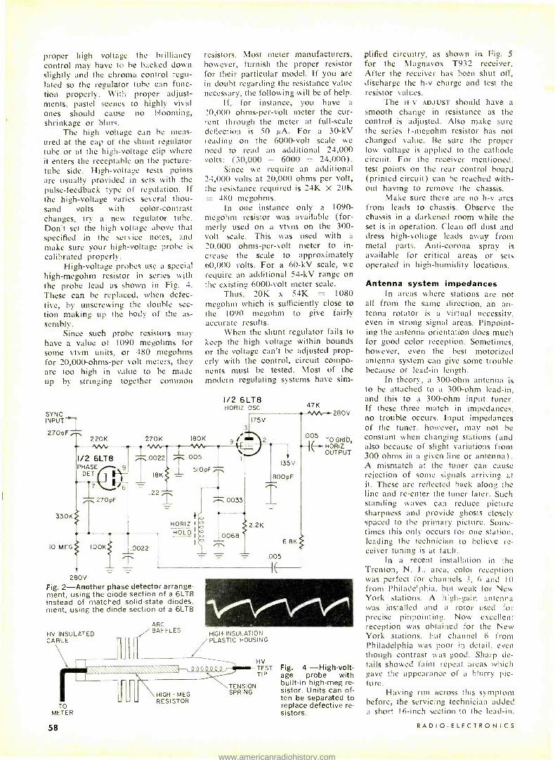
proper high voltage the brilliancy control may have to be hacked down slightly and the chroma control regu- lated so the regulator tube can func- tion properly. With proper adjust- ments, pastel scenes to highly vivid ones should cause no blooming, shrinkage or blurs.
The high voltage can be meas- ured at the cap of the shunt regulator tube or at the high -voltage clip where it enters the receptable on the picture - tube side. High -voltage tests points are usually provided in sets with the pulse- feedback type of regulation. If the high -voltage varies several thou- sand volts with color -contrast changes. try a new regulator tube. Don't set the high voltage above that specified in the service notes, and make sure your high -voltage probe is
calibrated properly. High- voltage probes use a special
high -megohm resistor in series with the probe lead as shown in Fig. 4. These can be replaced, when defec- tive, by unscrewing the double sec- tion making up the body of the as- sembly.
Since such probe resistors may have a value of 1090 megohms for some vtvm units, or 480 megohms for 20,000 -ohms -per volt meters, they are too high in value to be made up by stringing together common
SYNC INPUT 270pF
330K
220K
resistors. Most meter manufacturers, however, furnish the proper resistor for their particular model. If you are in doubt regarding the resistance value necessary, the following will be of help.
If, for instance, you have a
20,000 ohms- per -volt meter the cur- rent through the meter at full -scale deflection is 50 A. For a 30 -kV reading on the 6000 -volt scale we need to read an additional 24,000 volts: (30,000 - 6000 = 24,000).
Since we require an additional 24,000 volts at 20,000 ohms per volt, the resistance required is 24K X 20K = 480 megohms.
In one instance only a 1090 - megohm resistor was available (for- merly used on a vtvm on the 300 - volt scale. This was used with a
20,000 ohms -per -volt meter to in- crease the scale to approximately 60,000 volts. For a 60 -kV scale, we require an additional 54 -kV range on the existing 6000 -volt meter scale.
Thus, 20K x 54K = 1080 megohm which is sufficiently close to the 1090 megohm to give fairly accurate results.
When the shunt regulator fails to keep the high voltage within bounds or the voltage can't be adjusted prop- erly with the control, circuit compo- nents must be tested. Most of the modern regulating systems have sim-
270K 180K
1/2 6LT8 ...0022 005 PHASE 9 6
l ','6 .22
16K
270 pF
IO MEG I00K .0022
T
1/2 6LT8 HORIZ OSC
3
9
510pF
HORIZ I
HOLD
.0033
.0068
T
47K
175V
2.2K
135V
800 pF
.005
6.8K
280V Fig. 2- Another phase detector arrange- ment, using the diode section of a 6LT8 instead of matched solid -state diodes. ment, using the diode section of a 6LT8
HV INSULATED CABLE
ARC f BAFFLES
TO METER
58
280V
.005 TO GRID,
-I E-- HORIZ OUTPUT
HIGH-INSULATION PLASTIC HOUSING
HIGH - MEG RESISTOR
TENSION SPRING
HV TEST TIP
Fig. 4 -High -volt- age probe with built -in high -meg re- sistor. Units can of- ten be separated to replace defective re- sistors.
plified circuitry, as shown in Fig. 5 for the Magnavox T932 receiver. After the receiver has been shut off, discharge the h -v charge and test the resistor values.
The H -v ADJUST should have a smooth change in resistance as the control is adjusted. Also make sure the series 1- megohm resistor has not changed value. Be sure the proper low voltage is applied to the cathode circuit. For the receiver mentioned. test points on the rear control board (printed circuit) can be reached with- out having to remove the chassis.
Make sure there are no h -v arcs from leads to chassis. Observe the chassis in a darkened room while the set is in operation. Clean off dust and dress high -voltage leads away from metal parts. Anti -corona spray is available for critical areas or sets operated in high -humidity locations.
Antenna system impedances In areas where stations are not
all from the same direction, an an- tenna rotator is a virtual necessity. even in strong signal areas. Pinpoint- ing the antenna orientation does much for good color reception. Sometimes, however, even the best motorized antenna system can give some trouble because of lead -in length.
In theory, a 300 -ohm antenna is to be attached to a 300 -ohm lead -in, and this to a 300 -ohm input tuner. If these three match in impedances. no trouble occurs. Input impedances of the tuner. however, may not be constant when changing stations (and also because of slight variations from 300 ohms in a given line or antenna). A mismatch at the tuner can cause rejection of some signals arriving at it. These are reflected back along the line and re -enter the tuner later. Such standing waves can reduce picture sharpness and provide ghosts closely spaced to the primary picture. Some- times this only occurs for one station, leading the technician to believe re- ceiver tuning is at fault.
In a recent installation in the Trenton, N. J.. area, color reception was perfect for channels 3, 6 and 10 from Philadelphia. but weak for New York stations. A high -gain antenna was installed and a rotor used for precise pinpointing. Now excellent reception was obtained for the New York stations, but channel 6 from Philadelphia was poor in detail. even though contrast was good. Sharp de- tails showed faint repeat areas which gave the appearance of a blurry pic- ture.
Having run across this symptom before, the servicing technician added a short 16 -inch section to the lead -in.
RADIO -ELECTRONICS
www.americanradiohistory.com

FROM HV RECT
H-V LINE 20KV TO PIX TUBE
6BK4 -A SHUNT REGULATOR
SPARK GAP
500pF
1 MEG IW
HV
ADJUST II<
TEST POINT
REAR CONTROL BOARD (PRINTED CIRCUIT)
+390V Fig. 5- Shunt -regulator circuit used in the Magnavox T932 TV receiver.
Fig. 6- Several lengths of twin lead can help solve lead -in length problems.
The result was complete restoration of picture excellence. This technique may be challenged by the newcomer who hasn't experienced this problem before. Many oldtimers, however, have long recognized the difficulties that specific lead -in lengths can cause. Often the experienced technician will carry several lead -in test sections of the type shown in Fig. 6. These vary in length from 6 inches to 2 feet, since a particular length is often best for a given installation.
Once the right length has been found, reception is rechecked on oth- er channels, because the added length to the lead -in may alter reception on one or two other channels. When this happens, the added section may have to be increased or shortened in length to reach a compromise for the affect- ed stations. Once the optimum length has been established, a section of proper length is soldered to the lead - in permanently. R -E
NOVEMBER 1969
BESTSELLING SAMS BOOKS for every electronics interest
1 -2 -3 -4 Servicing Automobile Stereo The "1 -2 -3-4 Method" is a simple, logical step - by -step process which helps do the servicing job in the easy way and the right way. This book first applies the Method to both mechanical and electrical equipment, and then proceeds to cover the electronic and mechanical principles of automobile stereo, fm multiplex, and tape cartridge systems. Finally, the book shows how to apply the "1 -2 -3 -4 Method" to auto stereo sys- tems. Includes a wealth of schematics, charts, and illustrations. Order 20737, only $3.95
Closed -Circuit Television Handbook. 2nd Ed. Explains in practical terms the basic concepts of CCTV systems. Describes the versatile appli- cations of closed- circuit television, and the equipment used. Subjects include cameras, monitors, video recorders, lighting, and signal transmission. Completely updated to include latest information. Order 20726, only $5.95
Antennas and Transmission Lines A readily understandable text and reference on the theory of antennas and transmission lines, using technician -level mathematics. The book opens with basic antenna theory, including point and array sources, wave interference, standing waves, collimators, lenses, apertures, and sim- ple radiators. It then proceeds to transmission lines and their design factors. The final third of the text covers a broad variety of antenna topics. An ideal book for home study and ref- erence. Order 20716, only $7.95
Record Changer Servicing Guide This book provides a complete understanding of record changers, how they operate, and the various systems employed. Provides detailed in- structions on how to track down troubles en- countered in record changers and how to repair them in the fastest and most effective way. Order 20730, only $3.95
Auto Radio Servicing Made Easy. 2nd Ed. Explains the circuitry of both new and old auto radios, covering each of the tube and transistor stages. Provides step -by -step troubleshooting and repair details; explains how to eliminate noise and interference, how to set the bias on output transistor stage without breaking circuit, how to determine correct bias on transistor stages, what to do about AVC trouble in tran- sistor radios, etc. Order 20719, only $3.95
ALL -NEW EDITION OF THE FAMOUS
Audio Cyclopedia Completely revised 2nd Edition by the renowned authority, Dr. Howard M. Tre- maine. This is the most comprehensive work on audio -virtually a complete refer- ence library in a single volume. Fully covers every phase of the subject, in- cluding all the latest developments, right down to the newest solid -state and inte- grated circuits. Contains authoritative, concise explanations of thousands of top- ics in the fields of acoustics, recording, and reproduction; covers basic principles, components and devices, film recording, studio techniques, motion picture equip- ment, audio installation techniques, audio measurements, etc. Each subject is lo- cated instantly through a unique chapter and paragraph numbering system. Sup- ported by over 1600 illustrations. This is truly the master reference work on the audio art. Order 20675, only $29.95
NEW 5TH EDITION OF THE WORLD- FAMOUS
Reference Data for Radio Engineers Now contains 50% more data to cover the developments of the past 12 years. Prepared by outstanding engineers, professors, and experts, under the direction of the Interna- tional Telephone and Telegraph Corporation staff. Provides comprehensive data on all basic phases of electronics, including tables, formulas, standards, and circuit in- formation- PLUS -all -new data on micro- miniature electronics, navigation aids, reliability and life testing. international tele- communication recommendations, switching networks and traffic concepts, and quantum electronics. Over 1350 illustrations 1196 pages. Order 20678, only $20.00
Amateur Tests and Measurements This new E & E book shows how to perform virtually all tests on amateur transmitters. re- ceivers, and antennas, and how to make re- quired adjustments. An invaluable book for the amateur who wants to maintain top operating efficiency. Order 65072, only $5.50
101 Questions & Answers About Amateur Radio
A handy and practical reference source pro- viding the answers to the most frequently asked questions about ham radio. An invaluable book for both the newcomer and the old- timer. Order 20731, only $2.95
Transistor Specifications Manual. 3rd Ed. Updated to include the latest 1969 transistors. Contains the electrical and physical parameters for virtually all of the transistors now in use. Electrical parameters include maximum collec- tor -to -base, emitter -to -base, and collector -to- emitter voltages; maximum collector current; power dissipation; and maximum operating tem- perature. Also lists frequency gain and leakage parameters. Order 20707, only $4.25
Fundamentals of Digital Computers An excellent introductory text to the general field of electronic computing. It enables anyone to acquire a good basic understanding of what computers do and how they do it. The book begins with a discussion of various types of computer applications and surveys the history and evolution of computers. Then, it discusses in detail subjects such as the functional organi- zation of a computer, the individual components of a computer system. data preparation, storage devices, input and output peripheral devices, conversion units, and the central processor. A comprehensive glossary of computer terms is inoluded. Order 20714, only
$5.50 SPACE AGE TECHNOLOGY SERIES Prepared under the guidance of Training and Retraining, Inc., this series of five books holds unusual interest for anyone who desires to leam about the application of electronics to space progress, and the vital role it plays in that tech- nology All texts are programmed -type. Inertial Guidance Systems. Order 20605, only $4.95 Controlled Guidance Systems. Order 20573, only $4.95 Synchros and Servos. Order 20533, only $4 99
and Masers. Order 20559, only $4.95 Microminiature Electronics. Order 20582, only $5.75 SPECIAL OFFER! All 5 Volumes at a savings, in beautiful slip case. Order 20724, on/y.$24.95 -- - - - - -- HOWARD W. SAMS & CO., INC.
Order from any Electronic Parts Distributor, or mail to Howard W, Sams & Co., Inc., Dept. RE -11 4300 W. 62nd St., Indianapolis, Ind. 46268
Send books checked at right. $ enclosed. Send FREE 1970 Sams Book Catalog
Name
Address
City Stale Zip
20737 20707 20726 El 20714 20716 20605 20730 20573 20719 20533 20675 20559 20678 20582 65072 20724 20731
Circle 31 on reader's service card _J
59
www.americanradiohistory.com

by J. MERINO Y CORONADO"
IT SOUNDS STRANGE TO SPEAK OF
"chemical tools" in electronics, but dozens of them are in use. Knowing when to use the proper chemical tool for a job can be just as important as selecting the right mechanical tool. We'll look at some of the important "groups" of chemical tools that make our work easier and more efficient.
Using lubricants Let's begin with lubricants. A can
of a good light machine oil is a must for general lubrication and to prevent rust in fine tools. So is a can of medium machine oil, the kind you use in your car. Next time you change the oil, buy a can for the shop.
Lubriplate is useful for tape re- corders and record changer parts, and so is Tuner Lube for TV tuners.
Ordinary grease can be used to prevent corrosion on battery termi- nals. This type of grease, or grease con- taining graphite (used for bicycle chains) is useful for gears, provided temperature does not run very high. Fiber grease should be used for high - temperature conditions.
A box of paraffin or household wax is useful to prevent tool rust, as a humidity seal for some types of coils and i.f. transformers or to secure ferrite tuning slugs in place. Heat from a soldering iron held near the coil for a
minute or two softens this wax, allow- ing the core to be adjusted as desired.
Silicone grease provides a heat - transferring bond when mounting power transistors.
If you service organs, piano grease must be kept in stock to lubricate keyboards and pedal lever systems. Never let oil or grease fall on the delicate switching system. If you do, clean it off with a camel -hair
'Research physicist, University of Mexico Profes- sor of Acoustics, Polytechnic Institute of Mexico
60
CHEMICALS The Secret Weapon
In Your Shop Cements, Cleaners, Lubes, and Solvents are
Tools. Use the Right One For Speed and Efficiency.
brush and solvent. Of course, ordinary and graphite grease may be used to lubricate keyboards and pedaliers; many technicians do use them, but it's better to use the right chemical tool.
A type of penetrating oil is called chemical wrench or Liquid Wrench. Rusted bolts in antennas or towers may be loosened two or three minutes after applying it.
Very fine instruments such as the movements of some medical electronic instruments (phonocardiographs, elec- troencephalographs and the like) are lubricated with watchmakers' oil. You don't need this special lubricant un- less you service this kind of equip- ment.
Cleaners and solvents Of course, every shop has the
best cleaner and solvent there is- water. But plain water is not enough. Glass dial covers and TV tubes may be cleaned with it, but it's better to use first a neutral soap and a soft- rubber or foam sponge -then water.
There are many glass cleaners on the market, but when the tube or dial cover is covered with dirt, it's better to start with soap and water and then use the glass cleaner. Of course, you may use detergents, but
some strong types may attack glass and fog it. Many glass cleaners and strong detergents can fog plastic. Fortunately several good glass and plastic cleaners are on the market. If you don't have time to experiment, better use them.
Acetone is a good solvent for speaker cement. Applied to a speaker - cone dust cover, it softens the cement so the cover may be removed with tweezers to be used again. Amyl ace- tate, a solvent used to remove nail polish, is much stronger than acetone but more volatile.
Before soldering a break in a printed circuit, a solvent must be used to remove the silicone resin or pro- tective cover used on it. Print Kote Solvent is useful for the purpose, as is the ordinary thinner solvent used by painters. Both are applied with a camel -hair brush, and several sizes of brush should be at hand.
Ordinary gasoline is the best sol- vent for grease and oil on screws, bolts and other heavy -duty parts. But don't forget it contains tetraethyl lead, a poisonous compound. After using ethyl gasoline wash your hands. In some places gasoline without lead may be obtained.
Carbon tetrachloride or "tet" is an excellent cleaner and solvent. Several manufacturers specify it for cleaning tape heads and capstans. Some kinds of rubber dissolve in tet, so be sure to note equipment manu- facturer's warnings.
A word of caution: continous breathing of carbon tetrachloride fumes can produce serious, permanent damge to internal organs. Be sure to use it only with plenty of ventilation.
There are several good tape -head cleaners on the market that do not contain tet. They may be used on most heads without danger, and a bottle is a good investment. So is isopropyl alcohol for the same pur-
RADIO-ELECTRONICS
www.americanradiohistory.com

pose. Avoid use of methyl alcohol: it is dangerous to your eyes. And don't forget ordinary alcohol is dena- tured. This means a chemical has been added to make it unsuitable for drinking.
A can or small bottle of contact cleaner should also be available. Un- like carbon tetrachloride, most contact cleaners contain a lubricant and an anticorrosive. Applied with a long, curved eyedropper or a spray extensior into a volume control, the chemical will saturate the inside and clean the sliding contact. Cleaning is especially important in the expression - pedal controls of electronic organs. Located near the floor, they are sub- ject to severe "dust storms." Volume controls used in expression pedals, un- like those in radio or TV sets, are moved many times per minute while playing a tune.
Insulating coatings There are many brands of liquid
tape" for low voltages up to 1000 volts. Some technicians brush a coat- ing or two on tools as a protection against electric shock. But if you're working with voltages of 400 or over no liquid tape is a safe substitute for rubber, bakelite or plastic insula- tion. Don't take chances, especially if you're working on or near a damp or wet area.
Red insulating varnish forms a good coat over solder connections. It also serves for sealing adjusting screws in i.f. transformers, organ tuning coils, etc. For this last purpose, a drop of nail polish is good enough.
In the old days electricians used a plain solution of shellac in alcohol as insulating varnish. (This solution may also be used to cover up cabinet scratches). When brushed over wires or printed circuits it takes at least 20 minutes to dry. For this reason, most
technicians prefer to use a silicone resin coating to restore the protective coating on printed circuits after a repair. Print Kote is one trade name for this silicone resin.
Cement types A good general -purpose and
speaker cement can be made by dis- solving clean celluloid or acetate film from old negatives in a solvent made with 50% acetone and 50% amyl ace- tate. A drop is useful for fixing knots in dial cords, loose coil windings, or to secure pointers on a dial cord. Don't use all- purpose cement to repair broken plastic or wooden cabinets. Plastic cement, bakelite cement or carpenter's glue are better choices.
For very strong joints, epoxy cement can be used. Epoxy will bond practically anything to any surface.
Dentists use a very strong cement that can be molded to practically any shape. Used for mending broken den- tal plates, this cement is made with a resin and catalyst and can withstand severe temperature and humidity. It is transparent, but may be easily colored. For neat work, dentist's ce- ment is a good choice, but it's quite expensive.
Loose rubber objects may be fastened with any rubber -to -metal
cement. (Loose drivers or wheels that must be fastened to shafts, for exam- ple.)
Wood glue is useful for repairing wooden cabinets, or for most wood - to -wood bonding. Many wood glues can not stand severe humidity.
Miscellaneous chemical tools Many other chemicals are useful
in any shop. Some are used daily; others seldom used -depends on the work you have.
For instance, sodium bicarbonate or ordinary baking soda is a must if you handle car batteries. A saturated tap -water solution helps in cleaning the terminals and boxes of batteries, and stops corrosion by neutralizing the sulfuric acid of any electrolyte which spills from the battery cells. When a drop of acid falls on the floor or your hands, use the solution liberally as a neutralizer, followed by plenty of water.
Ordinary muriatic or hydroch- loric acid is used for some types of soldering, but its main use is for clean- ing porcelain and porcelainized fix- tures. Remember that any strong acid is dangerous to your skin and very dangerous for your eyes. Use rubber gloves when handling strong acids.
A few words of caution: always remember to keep these chemical tools in clean. clearly labeled containers. Acids, denatured alcohol, carbon tet- rachloride and any chemical you do not know is harmless should be labeled POISON in big letters. Alcohol, gaso- line, solvents and the like must be kept only in small quantities and labeled HIGHLY INFLAMMABLE, or KEEP AWAY FROM OPEN FLAME.
As we have seen, there are many useful chemical tools for daily use. There are many others of minor or infrequent use. but all of them simplify and speed our work. R -E
61
www.americanradiohistory.com

ABC's of
IF YOU DON'T BREADBOARD CIRCUITS AND PROJECTS BEFORE you build the real things, you may be losing time and money. A few minutes spent breadboarding some new design or part of a construction project will familiarize you with the circuit theory, spot bugs, suggest improve- ments and develop your knowledge of electronics.
The cost of breadboarding even a complex circuit is usually pennies, since the components can be reused. And with careful work a forbidding new pulse. signal or control circuit becomes a familiar friend. Engineers breadboard their designs time and again.
Why don't you? Maybe it's because you haven't come across a good
description of what it's all about. Breadboarding is simply another kind of modeling, and many examples in other fields cone to mind.
Electronic modeling The architect's model costs a few dollars but shows
new perspectives on a building that will cost millions. The car stylist's clay model finally appears in thousands of real duplicates, but only after a long and sometimes painful
Circuit Breadboarding
Avoid costly mistakes with your electronic
projects by modeling them first. You'll
learn circuit theory better, spot troubles
and develop design improvements
by JIM ASHE
62
Vacuum -tube breadboard assembly
contains 7 -pin, 9 -pin and corn- pactron sockets. Grommeted holes carry
heater wiring.
Solid- state, metal - chassis
assembly can be used for fast, easy duplication of
numerous experimental transistor circuits.
RADIO -ELECTRONICS
www.americanradiohistory.com

evolution. Can you imagine building a complete new car to check out each styling or mechanical design idea?
Yet this same modeling concept seems to be pretty rare in ham radio. experimenter, hi -fi and other popular electronics fields. Let's look at this breadboarding idea from the special perspective of somebody interested in electronics.
Pick an electronic instrument, box or machine. It could be a standard vtvm, or if you're more ambitious you might choose a radio receiver or an oscilloscope. Only a glutton for punishment would choose a computer. Now open it and look inside. There are resistors, capacitors, transistors, IC's and perhaps vacuum tubes. There's also a lot of sheet metal, mounting hardware, pots. meters and other mechanical or electromechanical structures.
But most of it is of secondary importance. In there somewhere is the circuit, the collection of interconnected resistors, capacitors, inductors and active devices that ac- tually does whatever it is we say the box does. This circuit is the real heart of the electronic gear and in a very real sense the rest- perhaps 80% or more by weight -is simply extra trimming.
If you're thinking about building something new, it's not good planning to invest time and money in hardware and mechanical work until you are reasonably certain the result will be acceptable. And if you are a student or trying to upgrade yourself in your field. a good practice is to avoid routine mechanical construction work. It consumes time and money but does little for your mastery of new and all- important knowledge.
This key point seems to be almost invisible in popular and technical electronics, although most professional engi- neers, who are great breadboarders, see it clearly. When an idea or design is proved reliable. the most economical procedure is to work directly from the design to the fin- ished product. But proven reliability is one part skilled design, one part appropriate testing and one part under - standing-a not very common mix. Sometimes the idea - to- product process is good policy, but in real life the procedure in Fig. 1 has compelling advantages.
The original idea is modeled or breadboarded, and after observing the results we may change our thinking and try again. We may go around this loop several times for new work, but finally the ideas and design come into focus. We step out of the loop with a finished product, and from there we sometimes go to a real physical project. And if all we needed was a finished idea we've saved ourselves the time and expense of a hardware project. Fig. 1 illustrates the approach we use in breadboarding, and on many other occasions too.
Practical breadboards Once we have lowered our sights and set a limited
goal of testing and understanding circuits rather than con- structing hardware, our work becomes much simpler. Costs are reduced. too.
Elaborate circuit- construction kits have appeared on the market for this kind of work, but they do not seem to last long. Perhaps it's because kit designers have to overdo to have anything to sell. A breadboard that looks like a candidate for the junk pile will do as well as a commercial assembly, and though many of us will choose the better - looking gear, we will gain little from the additional ex- pense. A sample breadboard arrangement is shown in Fig. 2.
This is a piece of plywood with two three, or four short rows of tacks or nails driven into it. Two lengths of bus wire or strips of tin along the outer rows serve as supply and grounding lines. A bracket or brackets are provided to mount controls that are too heavy or that require too much torque to be left lying on the board or hanging in midair. Construction of a circuit on this bread-
NOVEMBER 1969
board is very simple and results in a neat job. To breadboard a one -transistor circuit, solder the
collector resistor to the supply line, add the transistor to the end of it (socket optional) and tack in the emitter resistor on the other side. Two additional resistors are the base bias network, and a couple of capacitors stick out the ends or sides for input and output.
There are no fixed input, output or supply terminals. Connections as required are carried in by clip leads, avoid- ing fussing around with mating connectors that add nothing to the progress of the work. When a wire doesn't reach, tack on a bit of hookup wire. Used parts, if they are known to be good, are excellent for practice, saving much money.
At radio frequencies some positioning of parts may be needed, but usually the distances provided by leads will reduce coupling to levels as low or lower than can be ex- pected in a finished circuit assembly.
This style of construction has proved adequate for a variety of circuits. One was a remarkably successful re- generative detector project, which did not seem to suffer from any of the disadvantages that appear unavoidable in this open, nonrigid construction. Evidently some old per- spectives about circuit construction need rearranging in the light of today's tiny solid -state electronics.
Careful construction is necessary to avoid an effect like that of a collection of springs. No soldered joint should carry appreciable stress or things will fly apart upon resoldering. Bend wires as needed to achieve con- tact, and then solder for electrical connections only. You will quickly develop an easy familiarity with this style of construction.
IDEA OR SCHEMATIC
BREADBOARD OR MODELING
OPERATION
ANALYZE RESULTS AND IMPROVE
DESIGN
TESTED DESIGN OR SCHEMATIC
CONSTRUCT WORKING MACHINE
(IF NEEDED)
Fig. 1 -Smart approach to project building calls for first building a model instead of a direct idea -to- product process.
BRACKETS IF NEEDED
1
ABOUT 3"
METAL STRIP OR HEAVY WIRE 1/2" OR 3/4" PLYWOOD
NAILS OR
TACKS
Fig. 2- Breadboard setups can be simple, like this plywood with nails, or more elaborate like the photos on the left
Table 1- Batteries for Breadboarding Eve -
ready Voltage and Num- recommended
ber current 1015 1.5V, 25 in A
1050 1.5V, 150 in A
276 9V, 30 in A 731 6V, 500 in A
732 12V, 250 in A
Size (inches)
35/64 dia x 1 31/32 long 1 21/64 dia x 2 25/64 long 2 9/16 x 2 x 3 5/32 5 3/8 x 2 7/8 x 4 15/16 5 3/8 x 2 7/8 x 4 15/16
Catalog Price $0.17 Pencell $0.20 Std. D cell $1.36 $1.96 $1.96
63
www.americanradiohistory.com

"Get more education or get out of electronics ...that's my advice ."
64
Expanded coverage of solid state electronics including integrated circuits ! s
RADIO-ELECTRONICS
www.americanradiohistory.com

NOVEMBER 1969
Ask any man who really knows the electronics industry.
Opportunities are few for men without advanced tech- nical education. If you stay on that level, you'll never make much money. And you'll be among the first to go in a layoff.
But, if you supplement your experience with more education in electronics, you can become a specialist. You'll enjoy good income and excellent security. You won't have to worry about automation or advances in technology putting you out of a job.
How can you get the additional education you must have to protect your future -and the future of those who depend on you? Going back to school isn't easy for a man with a job and family obligations.
CREI Home Study Programs offer you a practical way to get more education without going back to school. You study at home, at your own pace, on your own schedule. And you study with the assurance that what you learn can be applied on the job immediately to make you worth more money to your employer.
You're eligible for a CREI Program if you work in elec- tronics and have a high school education. Our FREE book gives complete information. Mail postpaid card for your copy. If card is detached, use coupon below or write: CREI, Dept. 1411H, 3224 Sixteenth Street, N.W., Washington, D.C. 20010.
r
,undid 1921
Amelia M,md t o/ the National Nom, Study Council
CREI, Home Study Division McGraw -Hill Book Company Dept. 1411H, 3224 Sixteenth Street, N.W. Washington, D.C. 20010
Please send me FREE book describing CREI Programs. I am employed in electronics and have a high school education.
MO,
NAME AGE
ADDRESS
CITY STATE ZIP CODE
EMPLOYED BY
TYPE OF PRESENT WORK G.I. BILL
I am interested in Electronic Engineering Technology Computers Space Electronics Nuclear Engineering Technology NEW! Digital Communications NEW! Industrial Automation
APPROVED FOR TRAINING UNDER NEW G.I. BILL
67
www.americanradiohistory.com

Assemblies like that of Fig. 2 can be made up from chassis and lug strips, as shown in the photos. They look better -perhaps electrically they are better -and they cost more. One is a solid state, the other a vacuum -tube bread- boarding assembly.
Around the breadboard If you automatically reach for an ac power supply
every time you think of a circuit experiment, you're miss- ing the best part of the whole idea. Batteries have come back into style and are ideal for breadboarding work.
Their simplicity, isolation from power lines, general availability, electrical properties and stability are all well suited to breadboarding. You can assemble some batteries into a small box with switch and terminals, or choose a few handy sizes such as the larger transistor batteries. Avoid miniatures. The ultra -tiny penlight cells and gener- al- purpose 9 -volt radio batteries may seem attractive but they have no capacity. Look for lantern batteries or others of rather hefty construction.
Alkaline energizer batteries are nice if you are work- ing with heavy loads and high currents. This is unusual in most breadboarding, and they probably are not worth the extra cost. Some suggested batteries available at economi- cal prices are shown in Table I.
If you really have your mind set on power supplies, there should be a couple of them, or else one power supply and some batteries on your workbench.
Typical breadboards will contain somewhat less than all of an electronic system. Working on a receiver design, you may breadboard the tunable oscillator, simulate the age system, test the audio amplifier, or do other tests on only a part of the overall system. This excellent engineering practice has a couple of very important, unavoidable bits of theory connected with it.
The first is that electronic circuits and their inputs frequently interact. If you duplicate the interaction, the breadboarded part of a circuit cannot detect the differ- ence between your setup and the real thing. Driving or input sources typically have a source resistance and reac- tance, which can usually he duplicated by a little additional circuitry on the breadboard.
For example, suppose you are breadboarding a tape playback pickup circuit. How do you match the properties of the head? Simply by adding the equivalent circuit of the head to the breadboard (Fig. 3).
Similar arguments apply at the output side of the circuit. A loudspeaker is easily simulated by a resistor, but if you are checking an i.f. amplifier stage you may want to include the transformer as shown in Fig. 4. Some care- ful thinking will usually enable you to reconstruct real circuit conditions with reasonable accuracy.
A convenient arrangement for breadboarding opera- tions is to set your generators. meters and other test gear about 4 inches above the working surface of the bench. A simple shelf assembly will achieve this. The fronts of the instruments become far more accessible, and the hazards of dragging a shirt sleeve across all the loose ends projecting from the breadboard are nearly eliminated.
Breadboarding tips The purpose of a breadboarding project is to test
your thinking, not to replace it. Good breadboarding is a fairly cerebral activity. one of the reasons for its low cost. The first requirement is a goal, or purpose, for building the breadboard. This is expressed most effectively by a
schematic of the circuit, carrying notes about the circuit's anticipated performance. Results can usually be added to the schematic and corrections made as indicated.
Later a fresh schematic is drawn, giving a clear, con- cise summary of your results and finished design. The breadboard is dismantled, scrap materials and paper dis-
68
Fig. 3 -Tape -head equivalent circuit can be breadboard- ed by using an in- ductor, resistance and capacitor to simulate tape head inductance, resis- tance and wiring ca- pacitance. A resis- tor will simulate a loudspeaker at the output. The bottom resistor in divider network should be 10 ohms, not 10K.
Fig. 4- Breadboard simulation of an i.f. amplifier might in- clude use of an out- put transformer, and a resistor to du- plicate the input re- sistance of a diode detector.
FROM RF SIGNAL GENERATOR
INDUCTOR SIMULATES HEAD INDUCTANCE
I0K / RESISTOR SIMULATES HEAD DC RESISTANCE
READBOARD
CAPACITOR AMPLIFIER IOK
CAPACITANCE
T CIRCUIT
WIRING /1
DIVIDER NETWORK REDUCES I -2 VOLTS INPUT TO 1 -2 MILLIVOLTS TYPICAL TAPE HEAD OUTPUT LEVEL
1
10K SIMULATED LOAD -USE 1/2 W.
RESISTOR
carded, and the deck is cleared for your next job. When you have your breadboarded circuit assembled
on the bench, can you find your way around it easily? A bit of memorization will enable you to work more rapidly, and direct your attention to the problem rather than annoying details of color charts and data hooks. Memorize the color code in Table II, and learn how it is applied to resistors, capacitors and inductors.
Table 11
Color Codes Table III
The Magic Color Number Number Sequence
Black 0 Brown 1
Red 2 Orange 3 Yellow 4 Green 5 Blue 6 Violet 7 Gray 8 White 9 (Silver) 10% (Gold) 5%
1.0 1.2 1.5 1.8 2.2 2.7 3.3 3.9 4.7 5.6 6.8 8.2 (10)
Since you may be breadboarding elaborate circuits once you've collected some materials and experience. you soon begin to appreciate being able to spot instantly that 3900 -ohm (orange white red) resistor the schematic shows in the second transistor's collector circuit. Memorize the basic transistor lead configuration. too: emitter base collector, seen from top, goes clockwise.
Another handy bit of memory work is the series of magic numbers appearing in Table III. These are the same 12th roots of 10 numbers used for 10% values of resistors, capacitors and inductors. Compare this sequence with the resistor, capacitor and inductor values in catalogs. An- other 12 values are added to this sequence to specify all standard 5% values. Perhaps in a few years all R, C and L values will be in this system. R -E
RADIO -ELECTRONICS
www.americanradiohistory.com

BUILD Perfect Electronic Keyer
An automatic Morse code keyer loaded with IC- controlled features.
by W. O. HAMLIN, W6ENU
THE PERFECT ELECTRONIC KEYER CAN GIVE YOU PRE -
cise, fully automatic Morse code operation. Dashes are always three times longer than dots, and the design features self -completing dots and dashes, making it unnecessary to hold the key closed until either is completed
Closing one set of contacts on the double -contact key generates a string of dots as long as the position is held, and the other contacts provide dashes. Operating speed is controlled by a potentiometer. When both contacts are
Fig. 1 -Dual two -input gate, the 914 IC, is shown below with its base diagram on top. PEK uses both NOR and NAND cir- cuits.
Fig. 2 -Cross coupling of 914 provides a freerunning multi - vibrator (top, right) or a "memory" flip -flop.
TOP VIEW 8
NOVEMBER 1969
4 (GROUND)
PEK FEATURES Character and space memory (completes if key is released) Dashes always three times longer than dots. Squeeze keying gives dot -dash or dash -dot continually
when both sides of key are closed. (Start depends on which side is closed first.)
Loudspeaker and side -tone monitor jack for connection into receiver audio.
Keying relay output for connection into any transmitter keying circuit.
Lock -key to short across relay for transmitter tune up. Logarithmic speed control for linear change at fast and
slow ends.
held, a string of alternating dots and dashes (or dashes and dots) is formed. This makes it easy to form common letters such as C.
Unlike earlier keyer designs, a dot or dash is started the instant the contacts are closed -not at some indefinite time later. The PEK's built -in tone monitor is optional, since many ham rigs have side -tone monitors.
Building the PEK is a snap. Since 95% of the PEK's circuitry is inside the 11 inexpensive integrated circuits (IC's) used, even a novice can wire the PC board in about one hour.
VC C
RESET INPUTS
SET
VC C
OUTPUTS
OUTPUTS
69
www.americanradiohistory.com

Vcc
. TOGGLE INPUT .T
2 KO 3 Gnd
PRESET (SETS ° "LOW)
OUTPUTS
J K O
HIGH LOW HIGH LOW
LOW HIGH LOW HIGH
LOW LOW CHANGES STATES
HIGH HIGH NO CHANGE
Fig. 3 -JK flip -flop used in PEK, the 923, is shown in a top view. Unit is strobed at its input to change its states. Truth table for 923 JK flip -flop, shows all logic conditions. High is a positive voltage, low is near -zero.
Fig. 4- Complete schematic diagram of the PEK keyer. IC's and a printed circuit board simplify construction. Note that the IC just to left of Q1 is IC -1, not IC -2.
PARTS LIST
Cl, C2, C3 -0.22 uF capacitor C4- 100 -µF, 10V capacitor C5, C6- 10 -AF, 5V capacitor C7 C10 -0.003 µF capacitor C11, C12 -0.01 µF capacitor C13- 10,000 -µF, 10V electrolytic capacitor (Sprague 39D 109G016JT4
or equivalent)
All fixed resistors 1A watt, 10% RI, R11 -470 ohms R2, R3, R9, R13, R18 -3300 ohms R4- 18,000 ohms R5- 33,000 ohms R6-220 ohms R7 -1000 ohms R8, R16, R17 -820 ohms R10 -330 ohms R12 -(see text) R14, R15 -1500 ohms R19- 5000 -ohm linear potentiometer
VOL R19 5K 1
J 113 o
C3 J 22
To
I6K 2N3565
Q3 N3566
R5 33K
22011
CI
RI R3 3.3K
J1,Mr+ 47011
914
RK 0 4 2N3638 =
R20- 10,000 -ohm, CCW logarithmic potentiometer
Semiconductors DlD4--1N2069 diodes or equivalent Q1- 2N5134 transistor Q2- 2N3565 transistor Q3- 2N3566 transistor Q4- 2N3638 transistor ICI -1C4, IC6, IC7, IC10, IC11 -914 dual RTL gate integrated circuit
(Fairchild or ITT) IC5, IC8, IC9 -923 JK flip -flop integrated circuit (Fairchild or ITT)
MISC- Hathaway G -P1A6 relay (distributed by Compar.) Key: Brown Bros. UTL (without base) or BTL with base. Box: LMB model CO -3. Box: LMB model CO3.
A set of two PC boards for building the keyer, a keying relay and a
complete set of transistors and IC's is available for $24.95 post- paid. A Brown UTL key is $11.95. Write: Solid -State Services, 1720 Kimberly Drive, Sunnyvale, Calif. 94087 (Atten: W6ENU).
SPEAKER
c_
C4 100 !µF LD,
R20 SPEED IOK
R8 8200
...j± C13 10,000µF
F 10 - - - - - - -0- ---
IN2069(4411 D2
I 914
.22
R2 33K
R12* 7V
RIO 1 33011
RII 47011
DI
03
C6 01
TIO/5V 2N5I34
R17
l 16.3 a IVAC°
IH I
RYI IK
CITI 1 .011
82011 o o
DOT
I~ RI6 I_ 0 820í1C12
°M o OI - I
R15 1 DASH
1.5K I KEY BROWN UTL
[WITHOUT I BASE OR BTL
WITH BASE
MIN 6an 63 5 4 C8 54 5 4
.003
923 8. 914 B.
3
914
C7 T.003 R13 3.3K
C9 7.003
70
6 R14 1.5K
5 4
117 VAC
SI
S2 LOCK KEY
XMTR KEY
INPUT
(BOTTOM VIEW OF IC'S)
*SEE TEXT
- Rie
3_3K _- RADIO-ELECTRONICS
www.americanradiohistory.com

Keyer logic elements First, let's look at the IC logic elements that make up
the PEK. Two types are used: 914 dual two -input gates, and 923 JK flip -flops. Fig. I shows the dual -gate circuit and its basing diagram. Transistors Q 1 -Q2 form one gate and Q3 -Q4 form the other. Because resistors as used for loads and at the transistor inputs, these are called RTL (resistor- transistor- logic) circuits.
The basic circuit is called a NOR gate when the input is a positive signal. NOR means "not OR." By definition, an OR gate gives an output signal (voltage) when there is a signal at either input (either input or both inputs). The not OR situation arises when a positive input voltage causes a gate transistor to conduct so that the output voltage is a negative (inverted) signal. Since either tran- sistor can produce the same output results, the OR de- finition is satisfied.
In computer logic terminology, the opposing type of circuit is the AND circuit. Both one and the other input must have signals to obtain an output. The NOR circuit can satisfy this definition by operating in reverse, and with inverting output it is called the NAND circuit. There is no output when both inputs are positive. That is. both transistors are conducting and the output voltage is low. One transistor and the other must be turned off before the output level changes. Notice that the change in definition of NOR to NAND requires a change in signal definition
/OLUME (R19) POWER TRANS LINE CORD
Top view of the PEK shows positioning of speaker, transform- er and filter capacitor used. A crutch tip holds the speaker.
Printed circuit boards or perf -board arrangement can be mounted on lower side of the cabinet. Layout is not critical.
N O V E M B E R 1 9 6 9
from a high to a low voltage level. The PEK uses both NOR and NAND logic concepts, as well describe later.
A dual -gate IC such as the 914 can be cross -coupled to form a bistable flip -flop as shown in Fig. 2. In a flip -flop. when one side is on the opposite side is always forced off. Since a bistable flip -flop stays in one of these states until forced to change by an external signal, it can be used for a "memory."
If the gates are cross- coupled with capacitors and dc bias is applied to the transistor bases, the on -off condition cannot be sustained. Instead, the two sides go on and off alternately, or oscillate. This is called an astable, or free - running, multivibrator. In the PEK, it is used for the tim- ing oscillator and side -tone monitor.
The logic and base diagram for the 923 JK flip -flop is shown in Fig. 3. The device gets its name from the function of its J and K inputs. It must be "strobed" at the J input by a fast fall -time wave to trigger (change states). The truth table shows all logic conditions possible. "High" is a positive voltage: "low" is a near -zero voltage. For example, when the J input is high and the K input low, the output is a high voltage and the 0 output is a low voltage after the toggle input has been strobed. The JK's outstanding feature is that when both inputs are low it changes state each time it is strobed. This results in a frequency division of the strobing signal.
Note that in either type of flip -flop, when one output is high the other must be low, and vice versa. The preset "P" always sets the flip -flop the same way: when it is high the "1" output is low and the "0" output is high. Using these principles, the JK flip -flop in the PEK is used for frequency dividing to set the dot, dash and space rela- tionships.
How the keyer works The complete schematic of the PEK is shown in Fig.
4, and the waveforms in Fig. 5 help explain its operation. Keying pulses originate in the clock oscillator, IC1. Dots and dashes are generated independently from the same clock by the divider circuits: IC5 for dots, and ICS and IC9 for dashes. Both portions of the circuit work identi- cally, except the dash portion has an additional divider and decoding gate to make the dash three times longer than the dot.
Here's the circuit operation: IC3 is the input gate con- nected to the key. When the key is in neutral. the outputs of both gates (pins 6 and 7) are low. When the key is moved to the dot position, pin 1 is grounded, causing the output at pin 7 to go high. This sets the upper half of 1C4 so that its pin 7 goes low. This removes the preset voltage on pin 6 of IC5, a JK flip -flop, permitting it to divide the clock signal. It also sets the input to the lower IC4 gate low, and its output (pin 6) goes high. This voltage is in- verted in IC2 so that pin 3 in ICI goes low, thus starting the "clock" oscillator. Therefore the lower half of IC2 acts as a clock control.
The output of the clock (ICI, pin 7) first goes negative and is inverted in 1C2. This applies a positive signal to the toggle input (IC5, pin 2). When clock ICI switches to the alternate cycle, its output goes positive, so that input to 105 goes negative. This causes the JK flip - flop IC5 to change states, and its output at pin 7 goes from a low to high voltage, remaining high until the input action repeats itself.
Because IC5 flips only on positive -going signals of the clock, in effect it is dividing the clock frequency by one - half. This is the period of the dot. Pin 5 of IC5, which was low during the dot, goes high on the second flip of IC5 and sends a positive -going pulse through C7 and R13. This resets IC4 to its off state if the key has been opened, so that pin 7 is driven high. Thus. IC4 controls the dot
71
www.americanradiohistory.com

circuitry. As long as pin 7 is high, dots will be turned off, and when low they will be turned on.
Dash dividers 1C8 and IC9 and the clock are con- trolled by IC7 in the same manner that 1C4 controls dots. The clock waveform is divided twice, so the output of IC9 is one- quarter the clock frequency. The wave from IC9 is connected to an OR gate, the top half of IC10, along with the output of the first dash divider, 1C8. The resulting output is shown in Fig. 5. IC10 therefore acts to decode the outputs of 1C8 and IC9 into a dash.
Since independent circuits are used for dot and dash generation, dot -dash memory is inherent in the system. One problem exists, however: dot and dash dividers 105 and IC8 would start dividing immediately after a dot or dash is selected by the key, since their toggle inputs are tied to gether.
This is prevented by a dash -signal inhibit connection from the dash output of IC10 to pin 3 of IC5, and a dot inhibit connection from the dot output of IC5 to pin 3 of IC8. These connections are analagous to an interlock.
"Squeeze keying" is accomplished by feedback from C8 and C10. When a dot is completed, the positive reset pulse through C8 holds off any dot generation at IC3 (pin 3), but feeds through R15 to start a dash on pin 1 of IC7. Likewise, C10 performs the same function at the comple- tion of a dash by holding off more dashes at pin 5 of IC3, but starts a dot by feeding through R14 at pin 1 of IC4. Therefore, continuous alternation of dots /dashes will occur as long as pins 1 and 4 of 1C3 are held at ground by the key contacts.
The function of IC6 is to mix the outputs of the dot and dash generators and invert them so both a plus and a minus code signal is available to interface with trans- mitter circuits. The addition of a transistor amplifier and keying relay is the simplest way to meet any keying requirement.
Assembling a PEK A pair of PC boards are available, along with the
IC's and transistors used (see parts list). Pegboard con- struction can be used since the layout is not critical, but wiring runs should be kept as short as possible.
It may be necessary to shield the circuit from trans- mitter rf fields. Frequency response of the IC transistors exceeds 100 MHz, but induced rf signals over a few hun- dred millivolts can cause spurious triggering. Place the unit in an aluminum box, and bypass the leads going to and from the box with the capacitor values shown in Fig. 4. The monitor speaker is a 21/4 -inch transistor radio type, pushed into a chassis- mounted crutch tip (available in drug or hospital supply stores).
An inexpensive 6.3 -volt filament transformer is used with a bridge rectifier for the power supply. (The 6.3 volts may be available from an accessory plug on your equip- ment.) The 3.6 volts required by the IC's is obtained by dropping the rectified 6.3 volts through a resistor. Current drain is about 125 mA.
The value of dropping resistor R12 will vary accord- ing to the tranformer's internal resistance or the source resistance in the equipment. For a low- resistance source, the dropping resistor should be about 21 ohms. Measure the output voltage with the circuit drawing current to set it between 3.2 and 4 volts; decrease resistance for less than 3.2 volts measured and increase resistance for more than 4 volts.
Testing and troubleshooting With the dc supply voltage adjusted as described
above, and the key in the neutral position, the relay should be open. Moving the key so that pin 1 of IC3 is grounded should produce a string of dots, and grounding pin 3 of
72
1KEY CLOSES FOR DOT
THIS POINT IS HIGH ONLY WHEN KEY IS CLOSED PIN 7 IC3 - L
PIN 7IC4-1
PIN 3 IC2- -f
PIN 7 1C2 - L
PIN 7 IC5 I
PIN 3 IC4
DOT OUTPUT
RESET PULSE
DOT TIME
PIN 6 IC3 J
PIN 71C7-
PIN 3 IC2
PIN 7 IC2 J PIN 7 1C8
PIN 7 IC9 --I PIN 7 ICIO
PINS ICIO -J PIN 3 IC7 r
Fig. 5 -Dot out- put for various IC's is shown on top above and the dash output below the line.
Fig. 6- Voltage chart can be used to check correct operation of the circuit Value of H varies with supply load- ing.
L:LESS THAN 0.3V H: MORE THAN 0.6V IC3 should generate a string of dashes. Potentiometer R20 varies the PEK speed. If the operation seems improper, check the chart of Fig. 6, which gives circuit test -point voltage readings. An L on the chart stands for a low voltage and indicates readings for a saturated collector. This L voltage should be less than 0.3. An H stands for high voltage (collector of a transistor which is off). The H voltage should be between 0.6 and the power supply voltage, depending upon the resistance loading at that point. R -E
THIS POINT IS HIGH ONLY WHEN KEY IS CLOSED
DASH OUTPUT
0
o
RESET PULSE
VOLTAGE READING CHART
IC PIN
NUMBER NEUTRAL
KEY POSITION
DOT DASH
2 3 L H L
5 L L H
6 H L L
3 I H L H
3 H H L
6 L L H
7 L H L
4 2 L H L
3 L L L
5 H L H
6 L H L
7 H L H
7 I L L H
2 L L H
3 L L L
5 H H L 6 L L H
7 H H L
RADIO -ELECTRONICS
www.americanradiohistory.com

Channel Separation Nomogram
By MAX H. APPLEBAUM
WHEN A STEREO -FM RECEIVER IS
working properly, channel separation should be equal to or greater than the 30 dB the FCC requires of stations. Here is a nomogram you can use to measure and calculate separation.
Manufacturers often use the fol- lowing method to measure separation:
1. Feed a stereo signal (left or right channel only) into the antenna input of the receiver. The input signal should be about 1,000 µV.
2. Adjust the receiver loudness control to obtain 0.5 volt measured with a vtvm connected across the speaker terminals.
3. Switch the signal, at the gen- erator, to the other channel. Keep rf 3 at 1,000µV.
4. Read the resultant output level, on the vtvm, across the original speak- er terminals.
The separation in dB, for that channel, is 20 log,,,. This is a ratio of the output level of the desired channel to the output level of the undesired channel. It is simply the ratio of the voltage measured in step 2 to that of step 4.
A simpler method is to feed in the signal as described in step 1 and measure the channel separation direct- ly, without decoding the composite stereo signal. You can do this by view- ing the waveform on a dc scope con- nected to the receiver second detector.
Fig. 1 shows the ideal composite signal with the 19 -kHz pilot carrier removed. Such a waveform indicates infinite separation. In practice, how- ever, this is impossible to obtain. Fig. 2 shows the signal which you'd nor- mally see at the second detector. The amplitude of a signal of the left chan- .3 nel due to an input of the left channel only is represented by A. B represents the amplitude of a signal on the right channel due to an input on the left channel only.
Since these dimensions (A and B) are directly proportional to the voltages they represent, you can cal- culate the separation with this for- mula:
Fig. 1
Fig. 2
A I 0 -- 8 ` 6
5 - 4
J
i
ï
2------
.6
.5
Separation = 20 logo A/ B
Referring to the nomo, the cal -
NOVEMBER 1969
.2
culation is now completed by extend- ing a straightedge from the value of A on its column to the value of B on its column. The separation in dB is found where the straightedge crosses the cen- ter column.
In the example shown, A = 2, B = .05 and the separation is found to be 32 dB. R -E
NOTE: The nomogram may also be used to calculate separation when the measurements are taken as described at the beginning of this article. Re- member that scales A and B must al- ways be in the sanie units.
dB 60
50
30
-20
-I0
411111. --_._
.02
- .03
- .04
-- .05
- -.06
.08
.2
=.3
_ .4
=.5 .6
8
73
www.americanradiohistory.com

llilllllllllillll + ÿ;i
NEW Kit IG -57A
$13500*
NEW Kit IG -28
NEW Kit IP -28
$4750*
NEW Kit G R-78
$12995.
NEW Kit GD-209A
$14995'
74
NEW, Improved Heathkit IG -57A Solid -State Post Marker/ Sweep Generator ... Now With Built -In Video Sweep Modulator Now align virtually every color and B &W TV set on the market with the new Heathkit IG -57A. New built -in Video Sweep Modulation eliminates the need for external equipment -the 1G -57A and a scope arc all you need to check the overall frequency response from the antenna terminals thru the tuner, IF strip, video de-
tector to the color bandpass amplifier outputs. And you don't have to worry about video detector diode load. Another new feature is the addition of two in- dividually adjustable 15 volt bias supplies with switchable polarity. Additional features: 15 crystal -controlled markers for color bandpass, TV sound, IF fre- quencies between 39.75 & 47.25 MHz and picture & sound carriers for channels 4 & 10 ... switchable retrace blanking ... adjustable phase control ... trace reverse function for proper display ... built -in switchable 400 Hz modulator ... Zener regulated power supply ... external attenuator for 1, 3, 6, 10 & 20 dB steps
up to 70 dB ... complete with all test leads, cables, connectors & plugs. Put com- plete servicing facilities on your bench now, with the new Heathkit IG -57A. 14 lbs.
NEW Heathkit Color Bar -Dot Generator ... Advanced Integrated Circuitry Produces 12 Patterns Plus Clear Raster, Eliminates Divider Chain Instability Forever The new 1G -28 is the signal source for all color and B &W TV servicing. No other instrument at any price will give as much stable, versatile TV servicing capability. Its solid -state circuitry produces dots, cross hatch, vertical and horizontal bars, color bars, and shading bars in the familiar 9x9 display ... plus exclusive Heath 3x3 display of all these patterns ... plus a clear raster that lets you adjust purity without upsetting AGC adjustment. Fifteen J -K Flip - Flops and associated gates count down from a crystal controlled oscillator, eliminating divider chain instability and adjustments. And for time- saving con- venience the IG -28 has variable front panel tuning for channels 2 through 6. Plus & minus going video signals at the turn of a front panel control ... for sync, in- circuit video or chroma problems, use the front panel sync output. Two front panel AC outlets for test gear, TV set, etc. Built -in gun shorting cir- cuits and grid jacks too. Add any service -type scope with horizontal input and you have vectorscope display capability as well. Fast, enjoyable circuit board - wiring harness construction. You can't beat the Heathkit IG -28 for versatility or value ... put it on your bench now.- 8 lbs.
NEW Heathkit 1 -30 VDC Solid -State Regulated Power Supply The new modestly priced [P -28 is an excellent power supply for anyone working with transistors. Compact Heathkit instrument styling with large, easy -to -read meter ... two voltage ranges - IO V., 30 V.... two current ranges - 100 mA, 1 A. External sensing permits regulation of load voltage rather than terminal voltage. Adjustable current limiting prevents supply overloads and excessive load current. Convenient standby switch. Fast, easy assembly with one circuit board and wiring harness. Order yours today! 9 lbs.
NEW Heathkit GR -78 Solid -State General Coverage Receiver... Tunes 190 kHz To 30 MHz In Six Bands The new G R-78 combines wide coverage, superior performance nd portability with sharp styling to provide a remarkable value in general coverage receivers. Tunes AM, CW & SSB signals from 190 kHz to 30 MHz in six switch- selected bands. The all solid -state circuit employs modern FET's in the RF section and 4 ceramic filters in the IF to deliver maximum sensitivity and sharp selectivity. Bandspread Tuning is built -in, and can be calibrated for either Shortwave Broadcast or Amateur Bands. Completely portable ... comes with a nickel - cadmium rechargeable battery pack and built -in charger that operates from 120 or 240 VAC and 12 VDC. Many built -in features ... 500 kHz crystal cali- brator ... switchable Automatic Noise Limiter ... switchable Automatic Vol- ume Control . Receiver Muting . . Headphone Jack and many more. Order yours today. 14 lbs.
NEW Heathkit Deluxe Radio- Controlled Screw -Drive
Garage Door Opener Semi -Kit The next best thing to a personal doorman. The "wireless" factory assembled transmitter operates up to 150 feet away. Just push the button and your garage door opens and the light turns on ... and stays on until you're safely inside your home. The giant 7 ft. screw mechanism coupled with the '/1 HP motor mean real power and reliability and the adjustable spring -tension clutch automatically re- verses the door when it meets any obstruction ... extra safety for kids, pets, bikes, even car tops. Assembles completely without soldering in just one evening. Easy, fast installation on any 7' overhead track (and jamb & pivot doors with accessory adapter). Order yours now. 66 lbs.
Adapter arm for jamb & pivot doors, Model GDA- 209 -2, $7.95*
www.americanradiohistory.com
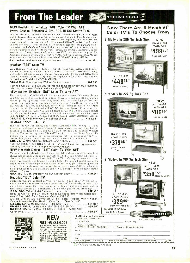
NEW Heathkit Ultra- Deluxe "681" Color TV With AFT ... Power Channel Selection & Opt. RCA Hi -Lite Matrix Tube The new Heathkit GR -68I is the world's most advanced Color TV with more built -in features than any other set on the market. Automatic Fine Tuning on all 83 channels ... power push button VHF channel selection, built -in cable -type remote control ... or you can add the optional GRA -681 -6 Wireless Remote Control any time ... plus the built -in self -servicing aids that are standard on all Heathkit color TV's. Other features include high & low AC taps to insure that the picture transmitted exactly fits the "681" screen, automatic degaussing, 2 -speed transistor UHF tuner, hi -fi sound output, two VHF antenna inputs, top quality American brand color tube with 2 -year warranty. With optional new RCA Matrix picture tube that doubles the brightness, Model GR -681MX only $535.00. GRA- 295 -4, Mediterranean Cabinet shown 5124.95'
Heathkit "295" Color TV With Optional RCA Matrix Tube ... with the same high performance features and built -in servicing facilities as GR -68l above ... less AFT, VHF power tuning and built -in cable -type remote control. You can add the optional GRA -295 -6 Wireless Remote Control at any time. New optional RCA Matrix tube doubles the brightness, Model GR- 295MX, $485.00. GRA- 295 -1, Contemporary Walnut Cabinet shown $64.95' Both the GR -681 and GR -295 fit into the same Heath factory assembled cabinets; not shown Early American style at $109.95' NEW Deluxe Heathkit "581" Color TV With AFT The new Heathkit GR -581 will add a new dimension to your TV viewing. Brings you color pictures so beautiful, so natural, so real ... puts professional motion picture quality right into your living room. Has the same high performance features and exclusive self -servicing facilities as the GR -681, except with 227 sq. inch viewing area, and without power VHF tuning or built -in cable -type remote control. The optional GRA -227 -6 Wireless Remote Control can be added any time you wish. And like all Heathkit Color TV's you have a choice of different installations ... mount it in a wall, your own custom cabinet, your favorite B &W TV cabinet, or any one of the Heath factory assembled cabinets. GRA- 227 -2, Mediterranean Oak Cabinet shown 5109.95' Heathkit "227" Color TV Same as the GR -58I above, but without Automatic Fine Tuning . same superlative performance, same remarkable color picture quality, same built -in servicing aids. Like all Heathkit Color TV's you can add optional Wireless Remote Control at any time (GRA -227 -6). And the new Table Model TV Cabinet and roll around Cart is an economical way to house your "227" ... just roll it anywhere, its rich appearance will enhance any room decor. GRS- 227 -5, New Cart and Cabinet combo shown S54.95' Both the GR -581 and GR -227 fit into the same Heath factory assembled cabinets; not shown, Contemporary cabinet $64.95' NEW Heathkit Deluxe "481" Color TV With AFT The new Heathkit GR -481 has all the same high performance features and ex- clusive self -servicing aids as the new GR -581, but with a smaller tube size . .
180 sq. inches. And like all Heathkit Color TV's it's easy to assemble ... no experience needed. The famous Heathkit Color TV Manual guides you every step of the way with simple to understand instructions, giant fold -out pictorials
. even lets you do your own servicing for savings of over $200 throughout the life of your set. If you want a deluxe color TV at a budget price the new Heathkit GR -481 is for you. GRA -180 -1, Contemporary Walnut Cabinet shown . $49.95' Heathkit "180" Color TV Feature for feature the Heathkit "180" is your best buy in color TV viewing ... has all the superlative performance characteristics of the GR -481, but less Auto- matic Fine Tuning. For extra savings, extra beauty and convenience, add the table model cabinet and mobile cart. Get the value -packed GR -180 today. GRS- 180 -5, Table Model Cabinet & Cart combo $42.50' Both the GR -481 and GR -180 fit the same Heath factory assembled cabi- nets; GRA- 180 -2, Early American Cabinet $94.95'. Add the Comfort And Convenience Of Full Color Wireless Remote Control To Any Rectangular Tube Heathkit Color TV ... New Or Old! Kit GRA- 681 -6, for Heathkit GR -681 Color TV's 564.95' Kit GRA- 295 -6, for Heathkit GR -295 & GR -25 TV's $69.95' Kit GRA- 227 -6, for Heathkit GR -581; GR -481 & GR -180 Color TV's .. $69.95'
1 T
N O V E M B E R 1 9 6 9
NEW FREE 1970 CATALOG! Now with more kits, note color. Fully describes these along with over 300 kits for stereo /hi -fi, color TV, electronic organs, elec- tric guitar & amplifier, amateur radio; marine, educational, CB, home & hobby. Mail coupon Or write Heath Company, Benton Harbor, Michigan 49022. L
Now There Are 6 Heathkit® Color TV's To Choose From
2 Models In 295 Sq. Inch Size NEW Kit GR -681 With AFT
$49995* (less cabinet)
Kit GR -295
$44995* (less cabinet)
2 Models In 227 Sq. Inch Size
NEW Kit GR -581 with AFT
$41995* (less capinet)
Kit GR -227 NOW ONLY
$37995 (less cabinet
& cart)
2 Models In 180 Sq. Inch Size NEW
Kit GR -481 with AFT
3599* ìabinet)
Kit GR-1 80 NOW ONLY
$32995 "_
(less cabinet & cart) Reception Is Simulated
On All Sets Shown
HEATH COMPANY, Dept. 20 -68 Benton Harbor, Michigan 49022
Enclosed is $ plus shipping.
Please send model (s) Please send FREE Heathkit Catalog. Please send Credit Application.
Name
Address
a Schlumberger subsidiary
City State Zip *Mail order prices; F.O.B. factory. Prices & specifications subject to change without notice. CL- 368
Circle 33 on reader service card 77
www.americanradiohistory.com

E ECIII CAPACITORS FIATO AND VARIABLE L. 'r .1V* CAPACITORS. ARSO ANO VARIARLE
P
= r_: "_ COILS-REIAYS iRANSEORMEAS e-"t WIRE CARES COROS ;EST EQUIP E4 +Tr iVICEAIOS I,-5 EWEIOMENIFRS AND SWITC*
IIA
t ar
3v5A
y::f:
:A :. ir,+
r
vl Mt
1110114111111 C
EÏEVÌ1È IN ELECTRONICS! MIAMI BALANCE STEREO HEAD PHONE
Harqut "'Sound level' control on. each
earpiece permits adjustment. Frequency *ante: 20 to 20,000+ cps..
64' cord with stereo plug. Impedance 4 to 16 ohms.
Cat. No, Q4.132 517,95 Net
Over 800 popular, new Calectro products for every household use! Now at each location, hundreds and hundreds of items for everyone
hobbyist, enthusiast, amateur, executive, homeowner, do- it- yourselfer. See the SELF -SERVICE G.C. Calectro display
at your Calectro SUPERMARKET TODAY.
AOD10 ADAPTORS
".V.. Audio Adaptor has a phono pro jack ah one sad sod dual phono met
plugs oft the other.
Cat Ni. 0141$ SAS Net
"C" (F1ASARIGNT) TYPE CELL NOLDU Holds 4, 6volt "C" cells: connect with wires
Cat Na, P3-064 6.62 Net
. rALECTaO
r MO STATION WIRELESS INTERCOM
Lest plug into any electrical outlet Completely portable. Espand system anytime with additional units. Two
unit system complete in display pack
Cot No. M-11l $31.15 Ref
f3EPERIYETER3 MINT ROM m Contains a 3'4" r I" perforated board. IS terminals (No. 14 -636) rod 4 mounting feet wlscrews. Build small circuits. hobby and science projects. etc.
Cal. W.14á60 5.91 Net
41111111V6Pat 2 CONDUCTOR PHONE ?UK Plug has black or red plastic handle a /solder lug and clamp.
Cat. No. F2416 (Mock) 5.113 NM
Cat Ne. f2417 (red) 5.13 Nd
ow* IAMf
type PR2.1.S volt 0.5O amp - Cat No. 12 43$ Pkg. of 2 $29 let Type PR3.3.6 volt 0.50 emp Cal Ne. E231 Pit. el 2 1211$0
Type 17.6.7 volts 0.15 amp Cat Re. F2á35.5,31 fat *I
type 40.6.3 volt O IS amp
Cat Ne E2á37 Pig. of 2 8.21116d
Type 466.3volt 0.2S amp -
Cal. W. £2111 Pat of 2 5.21 Net
TV WIRE rumor, NOLOERs
Wood rue. type.. 34' long, Insulates
üh "llat-line," foam and LOAM fthli0E.
r t its 12.050 Mg. S N S42 let Sa1Lé u above, bus Irr" Ioni Cat Na. 12A51 Kg. et3 Sal Aid
Soap-oll typt. fits on 14' mews..
tlnibers4E insulation foe all typo reif
cable.
Cat Re. 32.062 Pkg. e(2 ESA let
fEMSTORS Attractively packaged 2 pee pack. showing values. color codes and formula
Typs Carbon
Carbon
Cuckoo
Wire Wound
Rating Watt
-l0% 1 Watt -10% 7 Watt -10% 10 Watt - 10%
Saes Avaflalrle Prki uiiN 10 0hm 5.19 Pkg. d 2
10 Meg
10 Ohm. .19 Ea.
1 Meg
10 Ohm .15 Ea 100k
10 Ohm. .36 Ea.
ISK
STANDARD 1000 VOLT CAPACITOR
Nigh quality compact and reliable. Minimum capacity change with varying temperature. Rating: 1000
volts; tolerance: 20%.
Cat Ns Dsscript or Not Wit A1.060 220pF 5.25 Pig. of 2 A1.061 330pF .25 Pkg of 2 Al -062 170pF 25 Pig. of 2 A1.063 680pF .25 Pkg.. at 2 A1.064 0.001uF .19 Ea.
AI -065 O.00SuF .19 Ea. AI.066 0.010F .19 Ea.
www.americanradiohistory.com
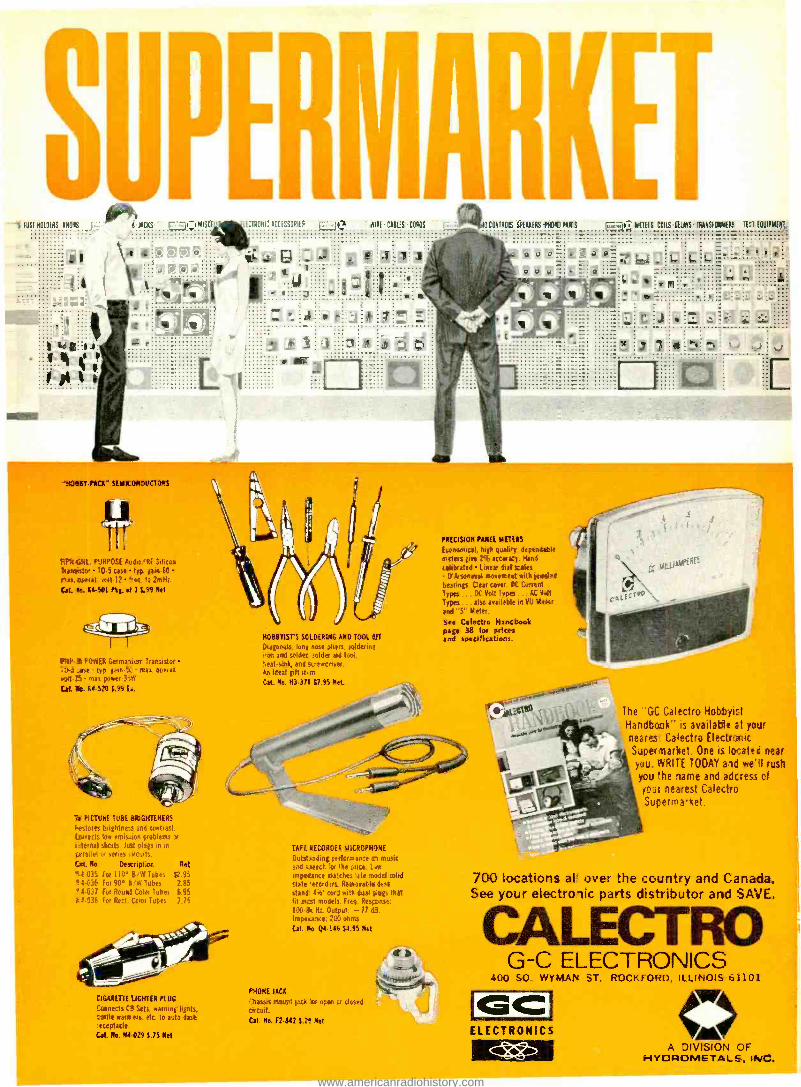
S-FUSEHOIOERS kNOHS
.
1,0
mmr
PICKS ri MISCEI' EMIR; 4CEESSCPI
o <s
L1
V %
AIRE CABLE CORDS
'Mt BT-PACI SEMICONDUCTORS
Fliig.C.Nt. PURPOSE Audio /RF Silica. leaneistm 10.5 case Ins gain50 r+ms. °petal. volt -I2 trop ,o 2mH:.
Gat 1e 144501 Pkg. el 3 5.99 Net
FhYiP 41 POWER Germaa:um Transistor TU -3 fast typ. gam5C mat operat voH-r5 mail power3'iYr
Cat No. M-520 899 b.
HOBBTISTS SO'l0ERBIG ANO TOOL UT Diagonals. long nose pliers. soldering too and solder solde aid tool, beat sink, and screwcnver. An ideal grit st. m
Cat No. H3 -371 17.45 Net
PRECISION PANEL METERS
Ecaammtcat, high quality dependable meters give 296 accuract. Hand
calibrated Linear diet =ales D'Arsanaval movement with ieoWea
bearings. pear cover. OC Current Types , . , OC Volt Typos ... AC Melt
Types . , also available in VU Meier
tnd'S" Meter.
Sae Colectro Handbook page 38 for prises and specifications.
The "GC Calectro Hobbyist Handbook' is available at yoar neares Calectro Electronic Sjpernarket. One e, lo- atet3 near you WRITE TODAY alc we'll rush you the name and adctess of
SOUL nearest Caie.tro Supermarket.
TM PICTURE TUBE BRIGHTENERS
Restores brightnes and contrast. Collects low emission problems or
Maternal shorts. hat plegs in in
garallet or stiles circuits.
rait. No. Description Net
94.035 Fus 110' BAN Tubes 1;7 95 F 1.038 For 90' BIW Tubes 285 PA-037 For Round Color Tubes 6.45
164 -538 For Rect. Color Tubes 7 15
CIGARETTE UG!TER PLUG
Connects C4 Sets. warning lights, tattle warners etc. to auto dash 'eceptacle Cat. Ne. N4-029 675 Net
TAPERECOIOER MICROPHONE
Outst,sdmg performance o music and speech '.!or the price. L:w impedance matches ',ate model solid state -word rrs. Remsvabtndesk stand d'o' cod with dual plugs that fit mat models. Fier,. Response:
t0ß-& Ht. Output: -17 dB. Impeaance- 280 ohms
Cat- No. Q4 -144 $4..95 Not
PHONE MCI Chassis moot jack br open er closed circuit.
Cat. No- F2 -142 Sit Net
700 locations al over the country and Canada. See yo;3r electronic parts distributor and SAVE.
CALECTRO G-C ELECTRONICS
400 SO. WYMAN ST. ROCKFORD, ILLINOIS 61101
GC ELECTRONICS
A DIVISION OF ü-IYOROMETALS, INC.
www.americanradiohistory.com

rti. in coupon for a FREE One Year Sub1 scription to OLSON ELECTRONICS Fantas-
ic Value Packed Catalog - Unheard of LOW, LOW PRICES on Brand Name Speak- ers, Changers, Tubes, Tools, Stereo Amps, Tuners, CB, Hi -Fi's, and thousands of other Electronic Values. Credit plan available.
NAME
ADDRESS
CITY STATE
GIVE ZIP CODE
If you have a friend interested in electronics send his name and address for a FREE Sub- scription also,
OLSON ELECTRONICS 512 S. Forge Street, Akron, Ohio 44308.4
ELECTRONICS
FREE Cat alo 9
Circle 39 on reader service card
.41111111111- More and More Technicians Say:
"We've tried cheaper substitutes ... now
WE'RE BACK TO
DEPENDABLE, RELIABLE
OISE" World's No. 1 TRUSTED NAME BRAND
VOLUME CONTROL & CONTACT RESTORER TUNER -TONIC with PERMA -FILM EC -44 FOR ELECTRICAL CONTACTS TAPE -RECO HEAD CLEANER FRIGID -AIR CIRCUIT COOLER
All Guaranteed Non -Flammable, No Carbon Tet, Non -Toxic, Non- Drift Tuner Cleaner And Guaran- teed Not To Affect Plastics.
The Only Brand Perfect For Color TV and Black & White
FREE extender assembly for pin - point application supplied with ALL NO -NOISE PRODUCTS.
Electronic Chemical Corp. 813 Communipaw Ave. /Jersey City, N. J. 07304
Circle 40 on reader service card
Use Christmas Seals.
It's a matter of life and breath.
1969eNRIstMAs $ r G1tKET/NGS1369
^ t r -v.
l9cJ»'.',îl `,,'i ¡ GREET/NGS1969
Christmas Seals fight emphysema,
tuberculosis, and air pollution.
Space contributed by the publisher as a public service.
kk
IrA ^1 ull
11
r D 0 00 using a
conventional staple gun
d I> on wire?
J
No shocking recoil action ... no short circuits when wires and cables are fastened with an Arrow Staple Gun!
SAFE! Grooved Guide positions wire for proper staple envelopment! Grooved Driving Blade halts staple at right depth of penetration to prevent damaging wire or cable jacketed insulation!
271 Mayhill Street, Saddle Brook, N. J. 01663
Wire and Cable STAPLE GUNS
Fits any low voltage wire up to 3/16" in diameter.
Fits any low voltage wire up to 1/4" in diameter.
Model T -75
Fits any low voltage wire or cable up to 1/2" die.
Circle 41 on reader service card
E. Circle 38 on reader service card
www.americanradiohistory.com

NEW PRODUCTS More information on new products is available from the manufacturers
of items identified by a Reader Service number. Use the Reader Service
Card at the left and circle the numbers of the new products on which
you would like further information. Detach and mail the postage -paid card.
ENGINE ANALYZER KIT, Alodel KG- 303, uses a full -sized 21_" meter which has 4 rpm ranges from 0 -6000 rpm, two dwell -angle ranges from 0 -60 °, plus a 0 -16V voltmeter range. It may be used on 4 -, 6- and 8- cylinder engines with
(1140
3- or 12 -volt positive or negative ground ignition. This analyzer is able to test Points, distributor and spark advance, and fuses. It can also he used as a con- tinuity tester. 61s" high, 3'V" wide and 23:? deep. $19.95.- Allied Radio Corp., Chicago, Ill.
Circle 46 on reader service card
CASSETTE RE- CORDER, Model RK -99, offers 117 - Vac and battery operation as well as complete rec- ord and playback facilities. Features include piano key- board controls, record safety inter- lock (preventing accidental tape
erasures), and cassette "pop up" re- moval. Ac bias recording system with automatic level control permits distor- tion -free recording. Input for radio, phono or tape recorder: output for ex- ternal speaker or earphone. Recording time: 2 hours. 549.95.- Lafayette Radio Electronics Corp., Syosset, N.Y.
Circle 47 on reader service card
POWER SUPPLY, Model 1025, all - transistor power source with built -in meters to provide continuous monitoring of both output current and voltage. Out- put voltage is variable from 0 to 30 volts. Max continuous load current is 150 mA in the 0 -12V range, 200 mA from 12 to 24 V, and 300 mA from 24 to 30 V. Maximum ripple at full load is
NOVEMBER 1969
0.005'%. Power supply is fuse -protected against short circuits. Kit is $34.95; fac- tory -wired 849.95. -EICO Electronic Instrument Co., Inc., Brooklyn, N.Y.
Circle 48 on reader service card
AUTO TUNE -UP METER, Model ID- 29, weighs 23 z lb in polypropylene case; is completely portable. This meter uses no batteries and measures dwell, rpm's :ul de volts on any 4- cycle, 3 -,
4 -, 6- or S- cylinder engine with standard ignition. Signal and power received di- rectly from engine under test. $29.95. -Heath Co., Benton Harbor, Mich.
Circle 49 on reader service card
INTEGRATED AMPLIFIER, Model AS -200, is designed specifically for tape recording. It allows siumltancous record- ing and monitoring vvitli three tape
decks and facilities for playback from five tape decks. The differential amplifier ( a computer type circuit) eliminates output capacitors and their distortions. This amplifier delivers 50 watts per channel at 8 ohms, and 60 watts per channel at 4 ohms. Harmonic distortion is 0.5%. Features include: two loudspeaker out- puts for main and remote stereo speaker systems, tone -control selector switch, pushbutton input selectors, and high and low filters. $299.50. -TEAC Corp. of America, Santa !Monica, Calif.
Circle 50 on reader service card
AC LEAKAGE TESTER, Model 229, designed for testing 117 -V /ac appliances and electrical equipment. Performance comes within ±1.0 dB of normal per- ception curve, and leakage currents as
small as 5 mA can he measured. Built for use on production lines and "in- field" service applications. Ac ranges cover 0 -0.3, 1, 3, 10 mA; and ac voltage from 0 to 150 volts.- Simpson Electric Co., Chicago, Ill.
Circle 51 on reader service card
TAPE ERASER, Model 30 -140, can be used by hand or as table model. Hand-
held, the eraser is passed over the tape reel in a circular motion. As a table
87
www.americanradiohistory.com

BURGLAR ALARM Series 6000 solid state microwave Dop- pler Radar Systems in the UHF Range provide complete wall -to -wall, floor -to- ceiling protection for an area of up to 2500 feet per sensor.
Stable operation, with two alarm stages. Transistorized design, low power con- sumption, (less than 3 watt). Compatible with all other types of burgular alarm equipment. Modular construction, adaptable to every installation. Automatic, variable reset of alarm conditions, from 5 sec. min. to 10 min. plus. Low cost, only 5f to 15f per protected sq. ft., depending on final systems configuration. Designed for continuous, indoor operation and easy installation.
artronix SURVEILLANCE
716 Hanley Industrial Ct. St. Louis, Mo. 63144 Area Code 314 Phone: 644 -2456
Circle 106 on reader vii ice carte
model, tape reel is placed on the post and rotated. Can also be used for cas- sette recorders. Includes momentary switch and cord. $18.30. -GC Electron- ics, Rockford, Ill.
Circle 52 on reader service card
C -B TRANSCEIVER, Model 14 -523, portable, 5 -watt, 23- channel unit. Double superhet receiver has mechani- cal filter, an S and rf meter on the
rubber safety front panel. Final -stage efficiency is ß5 delivering over 3.2 watts rf. Sensitivity is 0.5 mV. Variable squelch, AN L, age. Weight: 3;z lb.- Claricon. Elizabeth, N.J.
Circle 53 on reader service card
METRIC HAND TOOLS, in size ranges from 3 non to 17 min. The line includes 18 midget. regular and hollow -shaft fixed- handle nutdrivers particularly use- ful in the assembly and servicing of European and other foreign -designed equipment. Two compact, pocket -size sets are available: Set No. 99- PS -41- A /A1 contains 7 hex socket, interchange- able blades with hex sizes from 1.27 mm to 5 mm, plastic handle and 4" exten-
sion. Set No. 99- PS- 51 -31M consists of 10 interchangeable nutdriver shanks with hex openings from 4 mm to 11 mm; handle and 4" extension.- Xcelite Inc., Orchard Park, N. l'.
Circle 54 on reader service card
STEREO BACKGROUND MUSIC SPEAKER Model :1P -9C. Flush- mount- ing ceiling speakers eliminate space and
decor problems. Each speaker sends sound forward in a broad pattern pro - viding even tonal quality throughout a
EVERYTHING PRICED RIGHT Our TREMENDOUS BUYING POWER & PURCHASING EXPERIENCE make is possible. We invest Thousands of Dol- lars (in just a single item) to create a good DOLLAR BUY, resulting in the AMAZING & EXCITING OFFERS that follow:
FREE $1 BUY WITH EVERY 10 YOU ORDER °ñ17silq,ty; FREE GIFT WITH EVERY ORDER TRANSISTOR RADIO esst type $1.50 good. bad. broken, as -is, potluck
TAPE RECORDER - ass rte,l type- 54 nod. bad. broken, as -is, potluck .
32' - TEST PROD WIRE deluxe quality, red or black .... Si HEARING AID AMPLIFIER Sl incl. 3 Tubes. :011ie. etc. las is) .. COLOR POWER TRANS- FORMER FORMER - G "..1 rot* mast $ 95 sels O1t I . I i, Price -430.75 6'
El N10 - STANDARD TRANSISTORS Si
PN & PM' 2N44. 2N414, etc. .
10- ASSORTED DIODE CRYSTALS S1 1x34, 1N48. INGO. 1N64, etc. .
6 - TRANSISTOR RADIO EAR. PIECES ,vtred complete with plug
$20 -SHURE M -7D DIAMOND S3 NEEDLE exact replacement
$15.00 TELEVISION PARTS Si "JACKPOT" best huy ever
10 - SETS PHONO PLUGS & Si PIN JACKS ItCA type
10 - SURE -GRIP ALLIGATOR Sl CLIPS 2 plated
111 50 - ASSORTED PRINTED CIR- 5l CUIT SOCKETS best types
10 SETS - DELUXE PLUGS & Sl JACKS aSSt for many purposes . - 70 -BRASS FAHNESTOCK CLIPS S1 L. popular type & size
nilu
3' JUMPER CABLES Mate RCA $1.19 Type Plug on Both Ends, 2 for
S1
300 - ASST. Va W RESISTORS Top Irrand. Short Leads, Excelloot 51 Selection
100 -ASST 1/4 WATT RESISTORS Si .stand. choice ohmage... 'rile in 5,r
100 -ASST 1/2 WATT RESISTORS Si stand. choice oh...... :,e in
70 - ASST 1 WATT RESISTORS $1 .stand, choice .,:ne in 5çé
35 - ASST 2 WATT RESISTORS Si stand. choice ohmage:. re in 5o 50 - PRECISION RESISTORS $1 ,,;.t. li.stprice $511 Osco .. 20 - ASSORTED WIREWOUND Si RESISTORS, 5, 10. 20 matt
4 - TOGGLE SWITCHES SPOT. SPDT. UPOT. DI'DT
$1
10- ASSORTED SLIDE SWITCHES Si SPST, SPOT. DPDT. etc.
TV TUNER - a +t. all new $
r mia1,1 IllakeS. I.es.. tubes
TV TUNERS asst. an ne,. standard 53 kes, including Tubes
WESTINGHOUSE STANDARD TUNER #17uv120nd1 - (wGrs 54 - GCGS Tubes)
UHF TUNER - TRANSISTOR $2.95 TYPE L;e,l in all TV Sets .... 48 - #3AG FUSES 10 AMP. Si popular type
COLOR -TV RECTIFIER - Used in mast color sel-6900 $1.95 kv 3 for 2- MOTOROLA HEP -170 RECTI- FIER A:II's . ml I )OOV Pn caver, all nUnyl.. t, 25OOMA C,u,tae ranging inn, 50I'IC io S1 Inl,n PIA'
50 - ASSORTED TRANSISTORS S1 big factory senntr- --,ld as-is METER SENTRY -SOLID STATE Proterts meter movement, up to
99e 25 amps sorge - 1 15 ASST. ROTARY SWITCHES S1 all popular types $2 value
3 - TOP BRAND 35W4 TUBES Si
1_1 15 - G.E. #NE -2 TUBES Sl Neon Glow I.amp fer tut uses
150' - M
BUSS WIRE c#ed cur hoo,ps. .p1 ,o,-oi2O ts. h ac Si
etc.
-1 8 - ASST. LUCITE CABINETS Si (tinge ,over. handy for parts
20- PENLITE BATTERIES 11/2v $1 15- BATTERIES C -cell similar 935 $1 10- BATTERIES D -cell similar 950 $1
5- BATTERIES (Transistor) similar 216 $1
-I 100' - FINEST NYLON DIAL $1 CORD best size, 0.28 gauge
3- ELECTROLYTIC CONDENSERS c.D. 5d 01-200 vnlls
3- ELECTROLYTIC CONDENSERS l'.D. -250 mud -3:10 Volts
IMMEDIATE DELIVERY . .. Scientific light packing for safe delivery at minimum cost. HANDY WAY TO ORDER; Pencil mark or write amounts wanted in each box, place letter F in box for Free $1 BUY. Enclose with check or money order, add extra for shipping. rearsheets will be returned as packing slips in your order, plus lists of new offers.
Minimum Order $3.00 Please specify refund on shipping overpayment desired: CHECK POSTAGE STAMPS
Si S1
MARKET SCOOP COLUMN 12" OXFORD SPEAKER. MP 54 Quality . . . Large Magnet
ni 10" PHILCO SPEAKER $2.69 -J Top Quality . - - Large Magnet
Li 8" OUAM SPEAKER - Large 51.94 Magnet - Special Roy
21/2" x 4" SPEAKER 69r Specíal It u.
S31/2" ial -
Pup ROUND SPEAKER 59r
pec
25 - 3900- OHM -7w RESISTOR S1 10% Corning glare..
20 - .47.600V CONDENSERS S1 White Ceramic C.D. -American
SPECIAL TUBE BUY 3CB6. 3DTG, 49e 4CSO. 12017, 1_í)H7. Each .... .7
10 - ASST. RADIO & TV TUBES Si Every Tube a good number
1-1 3- PRINTED CIRCUIT IF TRANS- $1 FORMERS 4-l.ng. 456 KC
5" UNIVERSAL TWEETER $1.29 1
UNIVERSAL 51/2'" PM S PEAKER S1
UNIVERSAL 4 PM SPEAKER 79c Junk, 5 n . .1,1:,11,)' 1ne y
3- ELECTROLYTIC CONDENSERS Si G.E. -200 /30/4/ 1Omfd -350 volts
Netae Cost of goods
Addreee Shipping estimated TOTAL
MERCHANDISE (our choice) with advantage to customer
BROOKS RADIO & TV CORP., 487 Columbus Ave., New York, N. Y. 10024 TELEPHONE
88 RADIO -ELECTRONICS
www.americanradiohistory.com

room. Can be used with home stereo systems; only one moderately powered stereo amplifier is needed. -Karlson Re- search and Mfg., W. Hempstead, N.Y.
Circle 55 on reader service card
SOLID STATE VOLT- OHMMETER, Model 116, is 5Y" x 69!i" x 27(i". This volt- ohmmeter achieves low loading (dc input is 11 megohms; ac input impedance is 1 megohm) as well as a sensitivity
that is 500 times as great as a standard 20,000 -ohms- per -volt volt- ohmmeter. The solid -state circuitry and 4h" 200 - MA meter are protected against burn- out. Peak to peak voltage ranges: 0 to
3.3, 33, 330, 1200 volts. Rias ac voltage ranges: 0 to 1.2, 12, 120, 1200 volts. Dc voltage ranges: 0 to 1.2, 12, 120, 1200 volts. Resistance ranges: 0 to 1,000, 0 to 100,000, 0 to 10 meg., 0 to 1000 meg. Kit is $29.95; wired model $39.95. -Electronic Measurements Corp., New York, N. Y.
Circle 56 on reader service card
COLOR GENERATOR, Model CG18, is an unusually compact unit providing 10 RCA color bars, full -line crosshatch, dots, and individual vertical and horizontal lines. The timer controls are on the front
panel, and range has been doubled to prevent the timers from jumping time. Special features include: interlace con- trol to stop clot bounce, crystal -controlled 4.5 -MHz sound carrier for adjusting fine tuning, and automatic shut -off when lid is closed. -Sencore Inc., Addison, Ill.
Circle 57 on reader service card R -E
WHY PAY MORE? You can buy for LESS at Edlie's
Be sure to send for our
MONEY SAVING CATALOGUE
HERE ARE JUST A FEW OF OUR SPECIAL
FREE
BUYS CARBON MIKE
Brand new -used for C. B., ship -to- shore, mobile, etc. American Made, push button type uses Western Electric Fl Carbon Mike element. PRICE ONLY $2.95 ea; 6 for $20.95
TRANSDUCER 200 K. C. Made by Brush. Brand new. For Air use with Marine Depth Finder Equipment or experimental purposes. PRICE ONLY $2.95
S. C. R. BOARDS Type A contains the following: 1 -12A, 200 P.I.V. S.C.R.; 1- transistor; 4 resis- tors; 2- diodes. PRICE 994 ea; 6 for $5.00 Type B contains the following: 1 -12A, 200 P.I.V. S.C.R.; 3- transistors; 1-100 ohm trimpot; 10- resistors; 2- diodes. Price -$1.39
Paco ST -26 FM TUNER -AMP. KIT Comes complete with a 66 page assembly and operating Manual for building this fine kit. Complete with 6 tubes and all major parts. It is complete in every detail except for a few minor parts such as miscellaneous hardware which can be easily obtained. Has output for stereo multiplex adaptor. Price for this FM tuner & amplifier kit only $14.95 Cabinet not included.
WESTINGHOUSE solid state MULTIPLEX ADAPTERS $3.95
Terms of sale: Full payment or 20% with order. Minimum order $2.00
Write for FREE 1969 Catalog.
EDLIE ELECTRONICS 1NC.RÉ11
2700 Hempstead Tpke., Levittown, N.Y, 11756
Circle 107 on reader service card
CANADIANS: Ordering is easy - we do the paperwork -- try a small order
_ atr.
IBM R
SE
8 assorted Unita we sail for 51 are loaded with over 150 valuable parta.
Incl. - Translator Condensers. Resist. ors, Heat Sinks, Di. odes, Etc.
8 for $1 100 for $10
o
o
WESTINGHOUSE ALL TRAN- SISTOR HOME OFFICE
MESSAGE CENTER Leaves messages for other for replay . . . Built in speaker /microphone for talk -into convenience . . . Re- cords up to 3 minutes of messages . . . Illuminated signal shows when a message is waiting. Control adjusts playback volume without affecting recol'din-
SOLD volume
. . IS Capstan Drive; BRAND NEW $10
1000 - ASST. HARDWARE KIT $1 screws, nuts, washers, rivets, etc.
300 - ASSORTED HEX NUTS $1 2/50. 4/40- 5/4(1, 6/32. 8/32 ..
250 - ASST. SOLDERING LUGS $1 best types and sines
250 - ASST. WOOD SCREWS $1 finest popular selection
250 - ASST. SELF TAPPING Sl SCREWS #0. #8, etc.
150 - ASST. 6/32 SCREWS and 150 6/32 HEX NUTS
150 - ASST. 8/32 SCREWS and 150 -8/32 HEX NUTS
150 - ASST. 2/56 SCREWS $1 and 150 -2/56 HEX NUTS
150 - ASST. 4/40 SCREWS S1 and 150 -4/40 HEX NUTS
s1
$1
150 - ASST. 5/40 SCREWS 51 and 150 -5/40 HEX NUTS .... 500 - ASSORTED RIVETS most useful selected sizes
S00 - ASSORTED WASHERS most useful selected sizes
$1
$1
100 - ASST. RUBBER BUMPERS Si for cabinet bottoms & other uses ..
100- ASSORTED RUBBER GROM- $1 METS best sines
NOVEMBER 1969
FLYBACK TRANSFORMER
We scooped the Market Latest type - standard for all 110° TV's RCA's design of large Coil produces 185V- assuring adequate width tsel Schematic Diagram application for any TV
List price $13.90
53 Your price
10 c off in lots of 3
110° TV DEFLECTION YOKE for all types TV's incl schematic .. $3
"COMBINATION SPECIAL" RCA 110° FLYBACK plus 110° DEFLECTION YOKE $51
90° FLYBACK TRANSFORMER for all type TV's Inel schematic .. 90° TV DEFLECTION YOKE for all type TV's tact schematic .. 70° FLYBACK TRANSFORMER for all type TV's incl schematic .. 70° TV DEFLECTION YOKE for all type TV's incl schematic .
2 - TV CIRCUIT BREAKERS S Rated 4.2 TO 5.0 AMPS, etc. .
70° COLOR color CRT's .
90° COLOR YOKE For all
CRT "9
$2
$2
s2
$2
1.10
0.95
Rectangular 19 to 25- Color $10.95
E E
E E
E E
-SHANNON MYLAR RECORDING TAPE 21/2" 3" 3" 31/4" 5" 5" 5"
5"
7"
7"
- 225' - 225' - 300'
- 600' - 600' - 900' - 1200'
- 1800' - 1200' - 1800'
..5 .. .. .. .. .. .. .. .. .
.17
.19
.27
.58
.62
.80
.97
1.49 .77
1.12
7" - 2400' 7" - 3600' CASSETTE 60 minutes
CASSETTE 90 minutes
CASSETTE 120 minutes
$1.79 2.95
_89
1.54 1.97
21/2" TAPE REEL 3" TAPE REEL
31/4" TAPE REEL 5" TAPE REEL 7" TAPE REEL .,
.04
.05
.06 .12 .14
2 -G.E. PIECES OF EQUIPMENT S1I stacked with over 200 useful parts 50 - ASSORTED MYLAR CON- S1 DENSERS popular selected types 3 - TOP BRAND SILICON REC- TIFIERS t sine. i01)1) i'iv 20 - ASST. PILOT LIGHTS #44, 4ti. 17, 51, etc.
s1
50 - ASSORTED #3AG FUSES $1 popular ampere ratings 4 - 50' HANKS HOOK -UP WIRE $1 assorted colors
100' - SPOOL SPEAKER WIRE 51 2 cosa. mini zip. clear. 101 u
5 - I.F. COIL TRANSFORMERS $1 450 -kc [or Trans(stor Radlos .... 5 - AUDIO OUTPUT TRANS- $1 FORM Sub -min for Trans Radios
5 - PNP TRANSISTORS general purpose, TO.5 case
5 - NPN TRANSISTORS $1 general purpose. TO -5 case
MOTOROLA HEP KIT -INTE- GRATED CIRCUITS INCLUDES -One .1 -5 flip flop. One Dual Buffer, One 4 -input Gate, Two 53.95 Dual 2 -Input fates, All Five
MOTOROLA EXPERIMENTER KIT IIEK -2 -9 Protects. instruc- tion,. enclosed. Includes 2 -FET, 2 --rran sIslors. Tips on using 53.95 FF.TS" & Cross- reference Guide.
100' - TV TWIN LEAD -IN WIRE S2 300 ohm, deluxe heavy duty, clear
UNIVERSAL TV ANTENNA Rack of net Mounting . . . $1,98 5 section rods
Circle 108 on reader service card
BONANZA "JACKPOT" not gata, not oil. but a wealth of Electronic $C Items- Money- Rock- guarantee .. , 40
ALL AMERICAN TUBE KIT 121155. 120E5. 1_5t'ä. 5005. $/ 35W4 -total list $9.10 UNIVERSAL MICROPHONE $2 regular /rem to /single & dual plug
CRYSTAL LAPEL M:CROPHONE SQR high impedance. 200.0000 cps .
STEREO HEADPHONES HI -FI Quality . - . Complete $5.95 with Stereo plug 50 - TUBE CARTONS (colored) $1 assorted sines for popular Tubes .. 4 - TV ALIGNMENT TOOLS $1 most useful assortment 50 - ASST. TERMINAL STRIPS 51 all types, 1 -lug to 0 -lug 25 - INSTRUMENT POINTER $1 KNOBS selected popular types 1 - LB SPOOL ROSIN -CORE S1 SOLDER 40/60 top quality 7 - TV ELECTROLYTIC CON- 51 DENSERS desirable types 5 - 6' LINE CORDS $ #18 Stranded Copper Wire 1 MOTOROLA PWR TRANSFORM $ my, Cif 150 /150v, 5.3v 1 10 - TRANSFORMERS assorted
$1 Audio Output., Chokes. 1, F, s, etc. 4 - 36" Hi -Fi CABLES RCA Molded Phone plug at one end stripped and tinned leads on other $1 end
3- ELECTROLYTIC CONDENSERS $1 most popular number 50/30 -150v
89
www.americanradiohistory.com

aximum Time In Shop 24 Hrs.
(WE SHIP C.O.D.) YOU PAY SHIPPING
$9.95 Black & White
or Color
UV Combo's $16.50
rice includes all labor and parts ex- ` pt Tubes, Diodes & Transistors. If
mbo tuner needs only one unit re- aired. disassemble and ship only elective unit. Otherwise there will e a charge for a combo tuner.
hen sending tuners for repair, r
ove mounting brackets, knobs, ind for dials, remote fine tuning a
engements and remote control driv units.
Il
tuners must hove remote control uni d /or mounting brackets removed befor
ner can be cleaned and repaired. Please move these accessories before shipping
we will not be responsible for loss or damage.
All tuners a by FACTOR
rINED
TE ANS with year eperience. in this specialized field tuners are ALIGNED TO MANU TURER'S SPECIFICATION on crys
tel controlled equipment and ai ecked on monitor before shippin
saure that tuner is operafin
GEM CITY TUNER
REPAIR SERVICE Box 6E Dabel Station
2631 Mardon Drive
Dayton, Ohio 45420
Circle 109 on reader service carri 90
Service Clinic
By JACK DARR SERVICE EDITOR
Horizontal phase vs color Why does the adjustment of the
horizontal -hold control affect the col- or while still holding the picture? I've seen this on a couple of sets. - E. K., Woodland Hills, Calif.
Color burst is taken from a keyed stage, and works exactly like keyed agc and sync separators. Un- less the keying pulse from the flyback is exactly in phase with the color
1
i BURST
i1 EQUALS -s..-
`
BURST OUTPUT
KEYING PULSE
[KEYING PULSE 8 BURST IN PHASE
l
I
BURST
I I
l EQUALS NO BURST OUTPUT, NO COLOR!
KEYING PULSE
OOPS -TOO LATE!
burst, you won't get any burst out- put, and away goes the color.
The horizontal hold has a far wider "hold range" than does the burst. Burst itself is actually only about 2 -3 µsec wide, sitting on the back porch of the horizontal sync, which itself is only 15 µsec. You've got to be right on the nose with your gating pulse, or the burst will find the "gate" slammed shut in its face!
Adding Speakers 1 need some information. 1 want
to add a speaker to a transistor ampli- fier, and the specs call for a 30-32 - ohm impedance. Only one speaker like this is listed, and it's a 4- incher. I need a bigger one, preferably 12 -15 inches.
What's a safe hookup, using reg- ular speakers ? -F. B., Tacoma, Wash.
There are several ways you can do this: four 8 -ohm speakers in ser- ies, two 16 -ohm speakers in series, etc. Anything that will add up to the 32 ohms you need.
If you can't find a big speaker, here's a sneaky way to do it. Use
four 8 -inch, 8 -ohm speakers in either of these arrangements. The "in- line" layout will give you something like a
sound column, and the square layout will work almost like one 16 -inch speaker. All voice coils must be in phase, of course.
Scope intensity- control burnout I have an old Knight scope that
I've overhauled. It keeps burning out the intensity control! What do you think ? -A.B. No. Miami Beach, Fla.
Here's a partial schematic of the voltage -supply network of a Knight 83YU144. Note the high negative voltage applied to the cathode and
2.0 MEG FOCUS
G3
1.0
MEG
1.0
MEG
.1, CRT
52/ GI G4
IOOK
500K INTENSITY
-1200V
3.3 MEG 15K
heater, and the positive voltage ap- plied to the screen (G2 /G4) .
Your intensity control will be in either the cathode -as it is here -or the control grid. In some scopes, there are bypass capacitors around this net- work; look for one. Otherwise, I'd sus- pect a heater -cathode short in the tube, or a wiring short if it's an old instrument. Try using a heavier wat- tage pot, say 2 -3 watts for this par- ticular control. R -E
1.0 if MEG ASTIG.
+250 V
This column is for your service problems -TV, radio, audio or gen- eral and industrial electronics. We answer all questions individually by mail, free of charge, and the more in- teresting ones will be printed here.
If you're really stuck, write us. We'll do our best to help you. Don't forget to enclose a stamped, self -ad- dressed envelope. Write: Service Edi- tor, Radio -Electronics, 200 Park Ave. South, New York 10003.
RADIO -ELECTRONICS
www.americanradiohistory.com
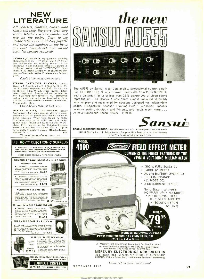
NEW LITERATURE All booklets, catalogs, charts, data sheets and other literature listed here with a Reader's Service number are free for the asking. Turn to the Reader's Service Card facing page 87 and circle the numbers of the items you want. Then detach and mail the card. No postage required!
AUDIO EQUIPMENTS, mono /stereo. including phonographs in the AVT Series and EDT Series plus headphones and listening center kits are illustrated in non- technical terms with photos in a 20 -page catalog entitled "NEWCOMB ". Items featured are useful especially for classroom pur- poses.- Newcomb Audio Products Co., Sylmar. Calif.
Circle 61 on reader service card
STEREO CARTRIDGE PLAYERS, 8- track. come in 5 models: all with a tape speed of 33/4
ips. frequency response, 40- 15,000 Hz and sig- nal -to -noise ratio, 50 dB. Three models feature power outputs of 10 watts and two include two 51/4" high- compliance speakers. Full description and specs of these units are described in Form CV -2174. 4 pages.-Telex Communications Div.. Minneapolis. Minn.
Circle 62 on reader service card
OUTLET PLATES, UHF /VHF FM include :Magna -Grip that holds antenna wire snug under pressure to assure proper lead contact for better signal reception. While wire cannot be pulled from plug. plug can be pulled from wall socket at any angle without damage to the wire or wall plate. Five models in the Colortap'Rotortap Series are described in Catalog "Get A Grip on A Profitable Market,- 4 pages.- Blonder -Tongue. Newark, N. J. R -E
Circle 63 on reader service card
U.S. GOV'T ELECTRONIC SURPLUS
Nationally Known -World Famous SURPLUS CENTER offers finest, most expensive, Government Surplus electronic units and cOmpenents at a traction of their original acquisition cost.
ORDER DIRECT FROM AD or WRITE FOR CATALOGS
COMPUTER TRANSISTORS ON HEAT SINKS IBM Computer Quality Wilts
t 522-9081-- Unit masts. or one 150. watt power transistor on heavy, ribbed, aluminum heat sink. Marty experimental Uses. a Ib.l $1.99 ' ° Coal f vt over 910.00 .-
(522- 916) -- rott mumieta of two 150. fi
-. wall power Iran.lslorv, 3 furs., Several diaries. :v,
'
es. capacitors. resistors. etc- on hea -.. ribbed aluminum heatsinks. Ideal for use as motor speed control. I A lbs. l
1.c.11 In,. 333.00 $4.91 t, I
RUNNING TIME METER i (SDK -104 1 -- use to record number of no- fit. .
devring hours of electric lights and electrical ices mull as refrigerators. furnaces. etc. Ì_ /d.
Records total hours. tenths and hundredths up_ 9,999.99 hours. For 115 -vnli. 60- rvcles.
titre 4,' u t" a','z '. Shipping might 2lb,. $5.69 Cello, ,,29.00
12 and 24 -VOLT TRANSFORMER ( x15-920) - .General F.lectrle 115 -volt, -
60 -cycle to 12 and 'M -volts w 150 -wall.. ` Capacity 44 -amps. . 24 -vol., 64-amps. at -
Y 12-volts. Useful for buttery chargers, running ut,, motors. etc. i x 5' a 5'. 110 lbs.) .r Cost Gov't Over 9:5.00 $16.72
EXPANDED SCALE 0 - 15 DCVM
(521-300)- - (band new, expensive voltmeter gads 9.5 to Itiolta Ill and 5 to Wvolts. Very useful
f -v
or automotive and aircraft battery charge Indicator, elf. Il'Arsonval move enl, black pneeue lyae. 2- g 5 a 2.8.. <3 lbs. i " . ,
rLt 932.50 $12.95
SURPLUS TELETYPEWRITERS
Orig. AM y(YIp.Ml122 lM
Model 13 can,tl.'ergbinhl
Oren A., Pen.. .111c Icle slip. f Y; " ple71N tun[ [
0oÌ telephone, 3r. at. 60 @. Sou SPECIAL sic a xx a ax ".
save w=: Model 19 oso ,. S2I9.50 sun penn.ter, par.a'o -.
Mae lu ball. p.c..
SEND 252 COIN OR STAMPS FOR CATALOGS
`W- xp "' All Items F08 Money Back Guarantee G
SURPLUS CENTER " - D EPT. RE 119 LINCOLN, HERR. 68501
111.111 Imr
the new 0
J L Z.I/ 555 0o4-(74,
Co, N-ae. pt'tR<rcrt
111,14,
The AU555 by Sansui is an outstanding, professional control ampli- fier. 60 watts (IHF) of music power, bandwidth from 20 to 30,000 Hz and a distortion factor of less than 0.5% assure you of clean sound reproduction. The Sansui AU555 offers almost unlimited versatility with its pre- and main amplifier sections designed for independent usage, 2- adjustable speaker damping factors, 4- position speaker selector switch, 4- outputs and 7- inputs, and much, much more ... At your franchised Sansui dealer. $159.95.
Sansui2 SANSUI ELECTRONICS CORP. Woodside. New York. 11377 Los Angeles. California. 90007
SANSUI Electric Co., Ltd., Tokyo, japan European Office Frankfurt a.M., West Germany Circle 111 on reader service card
MODEL
4000 Pfien / FIELD EFFECT METER COMBINES THE FINEST FEATURES OF THE
VTVM & VOLT -OHMS MILLIAMMETER
'
T.1, ....
.300 V. FULL SCALE DC LARGE 6" METER AC and BATTERY OPERATED HIGH IMPEDANCE (11 MEGS DC)
5 DC CURRENT RANGES
Solid State - so there's NO WARM UP! NO DRIFTI
NO INTERNAL HEAT TO UPSET STABILITY!
ISOLATION FROM AC LINE!
ONLY
7995
WIRED
Includes: AC- OHMS /DC Probe Power Requirements: 115 V 50/60 Hz, 3W
71/2 x61 /2x4 -3lbs. All Mercury Test Equipment Guaranteed For One Full Year!
Write for complete catalog of Mercury Test and Repair instruments, and name of your nearest dealer.
MERCURY ELECTRONICS CORPORATION 315 Roslyn Road Mineola, N.Y. 11501 (516) 742 -5400 CANADA: William Cohen Corp. 8900 Park Avenue Montreal -11
N O V E M B E R 1 9 6 9
Circle 112 on reader service card
91
www.americanradiohistory.com

UNEXCELLED! THE UI/N1 ANTENNA
UHF -VHF -FM COLOR
. . . J i_
Combination UHF -VHF -FM Antennas
at sui Tuned and engineered featuring a LOG PERIODIC VHF section incorporating a PATENTED MAGNETIC WAVE design for UHF. Discriminate between de- sired signal and unwanted noise. An absence of minor lobes and extremely high front to back ratio are characteristics of these antennas. Mechanical features include all new fittings and special alloy aluminum tubing for added strength. Six models available.
Write or phone for complete information.
S & A ELECTRONICS, INC. 210 W. Florence St. Phone (419) 693 -0528 Toledo, Ohio 43605
Circle 113 on reader service card
It's yours tree for the PA, asking!
j;fi-
1970 VADIO-TV ELECTRONICS CATALO(.
Ilk
YOUR BUYING GUIDE
GIANT 274 PAGE 1970
RADIO -TV ELECTRON I CS
CATALOG FOR... TV's, Radios, Recorders, Phonos, Amateur and CB equipment, electronic parts. tubes and test equipment ... featuring B -A's famous big bargain packed section! r Write to:
BURSTEIN -APPLEBEE CO., DEPT. RE -K 3199 MERCIER ST.,
KANSAS CITY, MO. 64111
Name
Address
City DIt,- State Zip Code ` J
92 Circle 115 on reader service card
WM COAX MATCHING TRANSFORMER
For UHF /VHF Color /B&W TV
One UHF or VHF Matching Transformer for either indoor or outdoor use. Mosley's new MTR -37A provides a perfect match of 300 ohm antenna or
receiver to 75 ohm coax. Solderless connections for easy installation
on antenna or TV set terminals.
Write Dept. 160A for FREE detailed brochure.
QWiky ás 4`e 4610 N. Lindbergh Blvd.,
/ia Bridgeton Missouri 63042
Circle 114 on render service card
Accuracy like a VTVM .. .
Convenience like a VOM... NEW BATTERY -OPERATED FET SOLID -STATE VOLT -OHMMETER --'116
Easy -to -build Kll
Factory -Wired & Tested
Now you can get all the benefits of a VTVM (laboratory accuracy, stability and wide range) but with its drawbacks gone: no plugging into an AC outlet, no waiting for warm-up, no bulkiness. New Field Effect Transistor (FET) design makes possible low loading, instant -on battery - operation and small size. Excellent for both bench and field work. Compare these valuable features:
High impedance low loading: 11 meg- ohms input on DC, 1 megohm on AC 500 -times more sensitive than a standard 20,000 ohms -per -volt VOM Wide -range versatility: 4 P -P AC voltage ranges: 0-3.3, 33, 330, 1200V; 4 RMS AC voltage ranges: 0-1.2, 12, 120, 1200V; 4 DC voltage ranges: 0- 1.2,12,120,1200V;4 Resistance ranges: O.1K, 0 -100K, D -10 meg., 0 -1000 meg.; 4DB ranges: -24 to - ( -56DB. Sensitive easy -to -read 41/2" 200 micro - amp meter. Zero center position avail- able. Comprises FET transistor, 4 silicon transistors, 2 diodes. Meter and tran- sistors protected against burnout. Etched panel for durability. High -impact Bake- lite case with handle useable as instru- ment stand. Kit has simplified step -by- step assembly instructions. Both kit and factory -wired versions shipped complete with batteries and test leads. 51/4 "H x 63/4 "W x 2% /a "D. 3 lbs.
Send FREE catalog of complete EMC line and name of nearest distributor. RE -11
Name
Address
City
State Zip
EMC ELECTRONIC MEASUREMENTS CORP.
625 Broadway, New York, N.Y. 10012
Export Pan Mar Corp 1710 B way Nt Nt 100ÚI
www.americanradiohistory.com

COMING
NEXT
MONTH
DECEMBER 1969
Automatic Antenna Rotators
The new breed uses solid -state electronics to make them do a bet- ter job. See how they work.
Transistor Curve Tracer
Want to know the char- acteristics of that un- known bargain -base- ment semiconductor? Use this instrument with your scope to find out. Build it with ICs.
Programmed Course Automatic -fine -tuning is here today in many of the new color sets. Here's a painless way to see how it works and how to keep it working.
Fuzz Box Another add -on for your guitar amplifier. Use it to add another dimen- sion to your electric music.
N O V E M B E R 1 9 6 9
Who needs a tuner
wash? Save your money and use
O U/E TROLE The product that cleans while it
lubricates. Zero effect on capacity
and resistance. Harmless to plas-
tics and metals. Keeps color and
black and white on the beam.
Non -flammable.
manufactured by
QUIETROLE co. Spartanburg, South Carolina
Circle 117 on reader ervice card
ARTISAN TRAITOR
CLPEEIC.L and THEAIEII styling for at CHJRCN -NOME- PRt1=ES9ONAL applicat ons.
ARTISANtonal zonceFts consoles and Elated mechanics are canpetely -RADITIQIAL in cesign.
Indtiilually keed osi lators end inda entent sets of
ton- generator: with separate arph'rrs End speakers assre t e find souni
Dis ettl voicel solo stcps that olend it raid E.-s=-mble.
Asserble your awn organ and sauge 40 %- 2 models in
KIT or ssembkd torn. In addition, we custom bald to you- :per ficatuns.
Taie your owi sourd w4h PLUG -IN 3ilurtable aortes.
var<tle VIBRNIDS .-nc TREMOLOS, s.utan, r- vsrbera boo aid REAL PERCUBS ONS.
For ces nptive liter tu e and address of you, Nearest dede
Wri e
ARTISAN ORGANS 1372 E Weliut Stiel Pasacena Oal f srni Ç I i06 213 449.01:4
Circle 318 on reader service card
lmenewzaI NEW GRID -CIRCUIT ANALYZER TUBE TESTER
QUICKLY PINPOINTS BAD, WEAK AND GASSY TUBES Built -in vacuum tube volt- meter circuit cuts through wasted motions to two un- failing tests; cathode emission and gas, grid emission and grid leakage - to pinpoint trouble sources. Reveals gas con- tent as low as 0.5 sources.
ONLY ONLY
95 KIT
$69.95 WIRED
affitaimsmisam I 40 ® 104)
Self- contained in ha-Ils3me luggage type scuff -p-:o' car-ying case.
Latest phosphor- bronze contact type sockets All sockets iden- tified All up -to -date pin straighteners Wide angle rugged meter with special Gas /Grid Leakage Arc Heavy Gauge 2 -color ano- dized aluminum panel Grid Leakage. and Gas Test 12 button, 3 position Switching System reduces the obsolescence problem to the vanishing point! TUBE DATA is not only up -to -date, but is kept up;o -date on a year m year cut basis! Data for over 3000 tubes is constantly reviewed and enlarged year after year!
All Mercury Test Equipment Guaranteed For One Full Year!
MERCURY ELECTRONICS CORPORATION 315 Roslyn Road Mineola, N.Y. 11501 1516) 742 -5400 CANADA: William Cohen Corp. 8900 Park Avenue Montreal -11
Circle 119 on reader service card
www.americanradiohistory.com

TECHNOTES G -E KE COLOR TV CHASSIS
Whenever power supply diodes CR109 or CRI10 fail, shunt a 0.001- µF, 1 -kV capacitor (G -E part ET- 22X58) across each diode. The ca- pacitors provide added protection against possible damage by voltage surges. -G -E Service Talk
GENERAL ELECTRIC KC -KD CHASSIS
Raster shading where the right half of the raster appears substantially
darker than the left may be observed during periods of no video modula- tion (camera changes, etc.). This shading may he accompanied by a retrace "snake." In either case make the following changes.
1. Change diode CR102 to a G -E type ET57X40. Move the anode (ground) end of CR102 to the posi- tive terminal of C132 -B (the uncoded lug of electrolytic C132).
2. Disconnect the end of R153 from the junction of C136 and C138
easy answers to common color complaints
Perma -Power puts back Color TV Quality!
Puts back brightness Color -Brite Picture Tube Briteners Color -Brite brings out lost sharpness and details of fading color picture tubes. Provides increased filament voltage to boost electron emission, returns full contrast and color quality. MODEL C -601 for round tubes Dealer Net $5.85
MODEL C -511 for rectangular tubes
Dealer Net $5.85
Puts back black- and -white
Color -Brite Isolation Briteners No Boost. Corrects for cathode -to- filament short causing loss of black and white video drive. Isolates the short, restores the black and white information that gives the color picture its quality. MODEL C -502 for round tubes Dealer Net $7.25
MODEL C -512 for rectangular tubes Dealer Net $7.25
Put Back Profit -Use Perma -Power Briteners
Free technical literature on request)
Puts back full voltage Automatic Voltage Regulator Automatically boosts voltage 10 volts when line voltage drops below 110 volts. Eliminates shrinking, loss of brightness, loss of convergence. Combats poor line voltage regulation, overloaded circuits. MODEL D -210 for appliances rated up to 400 watts Dealer Net $14.95
SAftta.,®- owQlt, COMPANY Division of Chamberlain Manufacturing Corp.
5740 North Tripp Ave. Chicago, III. 60646 Phone: (312) 539 -7171
Circle 120 on reader service card
and connect it to lug 8 of jack J101. If vertical retrace lines appear,
C611
.0018 470K 1.0068
R612 C621
VERT OUTPUT TRANS
VII -b
1/2
6FM7P YELLOW VERT 1
ET OUT- PUT
RED
VB CUT,
X TO / R154
CR102 1TOR233 0104 620 pF
R153\ 47K
K CUT
CUT,
---- y TO C1368 /I
C 138 TO LUG
RI80 33A 8,J101
GRAY WIRE
NOTE =CUT OR DISCONNECT LEADS AT °X° IAS 1
AND ADD LEADS SHOWN IN DASHED LINES.
CI39 .005
TO r CONTRAST CONTROL (BOARD
make the following changes. 1. Change R612 from 47,000 to
470,000 ohms, V2 watt. Disconnect the wire going from circuit -board ter- minal VB (or C6I2) to R154. (R154 is now excess and may be removed.)
2. Reconnect wire from VB to the cathode end of CR102. -G -E Techni -talk R -E
SOLVE YOUR TV REPAIR PROBLEMS WITH
TV TECH AID A monthly TV publication of actual re-
pairs, and troubles encountered in OUR busi- ness. The information will be gathered from technicians, field reps. and all the leading manufacturers.
TV TECH AID will present up to 40 dif- ferent trouble shooting cases each month. Each manufacturer will have its own page.
Each symptom will have a clearly marked schematic of the particular faulty stage. The faulty components, and corrections will be listed to aid in repair. No guess work.
It will contain current models, older models, circuit changes and modifications on various models as they occur.
The days of "Trial and Substitution" are over.
Time means money. Don't forfeit those valuable profits.
ONE repair is worth more than four times the investment.
Each monthly issue will contain a series of timely sheets and the cost to you is only 57.95 for a full years subscription.
TV TECH AID P.O. BOX 603 KINGS PARK, L. I. NEW YORK 11754
ENCLOSED IS A CHECK OR M.O. FOR $7,95 PLEASE SEND 12 ISSUES OF TV TECH AID TO:
NAME ADDRESS
CITY STATE 71 P
Circle 121 on reader service card 94 RADIO -ELECTRONICS
www.americanradiohistory.com

NEW BOOKS
RCA TRANSISTOR, THYRISTOR, & DIODE MANUAL, SC14,. Commercial Engineering, RCA Electronic Components, Harrison, N.J. 07029. 8 x 51/4 inches, 656 pp. Soft cover, $2.50.
A useful volume for anyone work- ing with semiconductors. Some 200 pages of text explain solid -state fundamentals clearly and in detail; chapters cover numerous device applications -TV, linear systems, power, switching and more. The technical data section provides detailed data and design curves for some 900 de- vices. Circuits section presents circuits and parts list for 38 solid -state devices - from code oscillator to FM stereo multi- plex decoder.
FEEDBACK AMPLIFIERS AND OSCILLATORS, by Robert E. Sentz and Robert A. Bartowiak. Holt, Rinehart and Winston, Inc., 383 Madison Ave., New York, N. Y., 10017. 6 x 9 in., 218 pages, soft cover, $3.95.
This is another in the Electronics Technology Series slanted toward tech- nical institutes and junior colleges. Re- quires a good grounding in electronic fundamentals and math. The various types of feedback and factors influencing feedback are described in the first three chapters. Other chapters analyse most types of oscillators, including crystal, negative -resistance. RC, LC and uhf and microwave oscillators. R -E
AL SERIES ALUMINUM
TOWERS for
uhf - vhf Ideal for mounting indus- trial, commercial, citizens band, amateur, or televi- sion receiving antennas. Exceptional strength in proportion to weight quali- ties. Easy access to equip- ment mounted on the Microflect top mast exten- sion. Other features are:
to to 120 feet high in easy to erect 10 foot sections. Available factory -assembled or in kit form. Lightweight, all aluminum, 10 foot sections weigh only 121/2 lbs. Low maintenance, will never rust or require painting. Staggered ladder treads for easy climbing. Can be used for direct radi- ator at HF. Wide variety of mounting brackets and accessories available.
DISTRIBUTOR INQUIRIES INVITED
M ICROFLECT 3575 25TH STREET
SALEM. OREGON 91302 AC 503 3639267 TWX 510 399 -0 101
Circle 122 on reader service carel NOVEMBER 1969
The brand for all reasons BSR McDONALD 600
Every B3R ILDonald automatic billable is precision Tiede in Great Britain to the vast exac:ing specifications. Upon thei- arrival h te. U.S., every model is unpacked and re -t s ec under actual playing conditions That's why BSR service calls a: e
the lowest in the industry -and perhaps that also atpains why BSR sells mhre turntables If an anyone else in the Nor +d.
BSR (USA) LTD. BLAUVELT, N.Y. 10913
Please send FREE detailed literature on all BSR McDonald automatic turntables.
Address
State
Mc DONALD
Circle 123 on reader service card
5" OSCILLOSCOPE 5 MHz HIGH SENSITIVITY WIDE BAND 'SCOPE PLUS
Input- Compensated VECTORSCOPE
Direct reading Graticule, in- stantly removable (2 supplied) plus special V input circuit
Peak -to -Peak readings as easy as reading VOM or VTVM
Vertical amplifier, 4.6 My RMS /Cm usable to 10 MHz for truly high sensitivity . . . 10 Hz to 5 MHz ± 3Db ... 0.08 Microsecond rise time
Horizontal amplifier, 5 Hz to 500 KHz
Internal, ex- ternal and line synch.
All Mercury Test Equipment
Guaranteed For One Full Year!
Power req. 115V 50 /óO Hz 85W. 11x9x1i6,22lbs.
The Mode,' 3000 is perfect for general purpose walreform obser- vation applications, meeting all the requirements of technical schools, industry, electronic experi- menters and Development engineers. Write for complete catalog of Mercury Test and Repair Equipment, and name of your nearest deader -
MERCURY ELECTRONICS CORPORATION 315 Roslyn Road Mineola, N.Y. 11501 (5161 742 -5400 CANADA: William Cohen Corp. 8900 Park Ave. Montreal
Th's BOOK is a 'must' "Servicing Color TV With The Vectorscope" $2.95
-11
- - - - -_
O f "
Circle 124 on reader service card 97
www.americanradiohistory.com

NNNNNNNuiiiuuiiuiuINNNNNNNNNNNNNNNu
E INTRODUCE E YOURSELF
mi to a line of products new in the U.S. from a new supplier
AUDIONICS, INC. Presents SINCLAIR - SINCLAIR is England's leading manufacture r of budget - audio and experimenter devices. Audionics Inc is quite
pleased to be the US distributor for Sinclair Ltd.
IC -10. The Sinclair IC -10 is o monolithic integrated circuit high fidelity amp and pre -amp. It has o peak - power output of 10 watts. As an audio amplifier, the IC -10 requires only the addition of volume and tone controls with related circuitry. No other transistors are - required to complete the operating requirements of the IC -10. The IC -10 may also be used as a servo - amplifier as it is d.c. coupled in both sections. Each IC -10 is fully tested and is supplied with complete instructions including a 32 page applications monual. - The frequency response of the IC -10 is flat within one decibel from 5hz to 100kHz. With a power gain of - 110 db, an output of 5 watts rms and a distortion - figure of only one percent, the IC -10 offers exceptional performance. $12.00 postage paid.
The PZ4 Stabilized power supply is designed for use - with the IC -10 or the Z -12 amplifier. The PZ4 comes - preset for 1 B VDC but is adjustable from 0 to 30 VDC. The PZ4 may be used with either 110 or 220 VAC. - Ripple is less than 20 my at any output up to 1.5 amps. Regulation is within 3 %. The PZ4 is fully transistorized - for stability and is an outstanding value at $13.95 - postage paid. - The Z -12 Integrated amplifier is a high fidelity unit measuring only 3" x 1 -1/4" x l -1/4". The Z -12 will - operate satisfactorily from 6 to 20 VDC. It may be used . in numerous home and commercial applications due to its wide range and low distortion combined with an - unusual amount of output. The Z -1 2's frequency response within one decibel ranges from 15hz to 50kHz. The Z -1 2's power response is within two decibels from 50hz - to over 20kHz with less than one per cent distortion. The Z -12 is direct coupled and is suitable for use with speaker systems ranging from 1.5 ohms to 16 ohms. - Measured at 3 ohms with a 20 volt supply the Z -12 will produce 13 watts of power, rms. This figure nearly - doubles when used with a 1.5 ohm load. The Z -12 weighs 3 oz. and comes fully assembled and tested. $13.95 postage paid. - The Stereo 25 pre -amplifier and control unit is de- - signed to he used with a pair of Z -12's and the PZ4 supply. It may be used, however, with any high quality basic amplifier. Controls are provided for bass and - treble boost and cut, stereo balance, volume and input switching. A tape output is provided. Frequency response is flat within one decibel from 25hz to 30kHz and down - only three decibels at 100 kHz. RIAA equalization is
correct within one decibel. The unit is finished ìn brushed - oluminum with black trim and solid aluminum knobs. Tested and shipped postage paid $28.95 . The complete system consisting of the Stereo 25, two Z -12's, and a PZ -4 may be purchased for $59.95. - Quantity users are advised to write Audionics Inc. for - pricing. - Send today for a descriptive brochure giving complete specifications of the entire group of Sinclair products including stereo tuners, amplifiers, and speak- - ers. - Dealer inquiries invited.
WRITE TODAY
FOR FREE DETAILS
OF THE ENTIRE
SINCLAIR- ADDIONICS LINE.
Z12
STEREO 25
Ipuuull 111111mm mom i AUDIONICS, INC. IN - 9701 S. E. Mill, Portland, Oregon 97216 IN - NAME MI MI - ADDRESS - - - - CITY - - STATE ZIP .
I Iuuuiauif1u ...........iu.uuiuuauIf1 Circle 125 on reader service card
98
TRY THIS ONE
COILED -CORD TEST LEADS
Delicate test instruments may suffer severe damage when their lengthy leads snag on tools or equip-
ment on test benches and land on the floor.
A partial cure for this hazard is to replace the regular -length test leads
SAVE ON EVERYTHING
IN ELECTRONICS!
Stereo hi -fi Tape recorders & tape Electronic & hobby kits CB 2 -way radios Radios
Shortwave Phonographs Amateur gear Automotive elec- tronics Tools & hardware Tubes, transis. tors, parts, bat- teries, books and more! . . .
552 -PAGE ALLIED 1970
CATALOG
Right off the press and crammed with values -our biggest catalog ever! Huge selections, low prices, fast service. Mail coupon below for your free copy. Hurry, while they last!
ALL /ED RADIO. Dept. 538 Please P.O. Box 4398, Chicago, Ill. 60680 Print
NAME First Middle Last
STREET ADDRESS or ROUTE & BOX NO,
CITY
STATE ZIP
Circle 126 on reader service card RADIO -ELECTRONICS
www.americanradiohistory.com

makes possible reception of .._al programming, transmitted
...surly 400 FM stations around the country. YOUR FM tuner or receiver can recover this "hid- den" music with the simple addition of an SCA -1. Hook -up in minutes -full instructions supplied. SCA -1 is self powered . . , uses all solid -state circuitry (FET'S, IC's, NPN's). Works with any quality FM Tuner or receiver. Send check or m.o. for either .. .
SCA -1 (Wired, ready to use) $64.50 SCA -1K (Kit, all needed parts) $49.95 Etched, drilled P.C. Board plus special IC
plus full construction plans $12.50 One year parts guarantee
Free national SCA station list supplied with every order SOLD FOR HOME USE ONLY
SCA Services Co., Inc. Box 601 Port Washington, N.Y. 11050
Circle 127 on reader service card
..r. oro,..v...LJ
1969
AMAZING OFFER
RADIO & TV SERVICE DATA Tour hest, complete source for all
needed RADIO and TV diagrams and helpful servicing data. Most amazing values. Only $2.50 00 $4 per giant volume. Cover all important makes. models f all periods. Use this , o
tire ail as your no -risk order form r'- NO -RISK ORDER COUPON
I TELEVISION SERVICE MANUALS 'opr n
t
v, TV ialn are Lest for taster, e.la er 'l'v repairs. Lowest priced. Factory data on practically all
Complete c suits. all needed alignments facts. ,tiring hoard views. waveforms, voltages, pnaluetion
changes, and double -page sehemalieo. Only $3 and $4 per large annual manual. Cheek volumes wanted, send
enure advertisement as your order form.
D New 1969 E 1969 TV.
COLOR 19681TV $4.` Ca
only 1967 TV.
$4.
1966 TV, $3. Additional 1965 TV, $3. 1965 TV, $3. 1964 TV, $3. r1 1963 TV, $3. Additional 1962 TV. $3. Early 1962 TV, $3.
C 1961 TV Manual. $3. 1960 TV Nla null. $3. Additional 1959 TV. $3. Early 1959 TV, $3. 1958 TV \l:uulal. $3. Additional 1957 TV. S3. 1955 TV, $3. E 1954 TV. $3. -T 1951 TV, $3.
7 Master Index to all TV & Radio Manuals. 250
RADIO DIAGRAM MANUALS Ilse , .,,r,. l :olio manuals that simplify
repairing. c. vthing you may need front recent radios to pre -,car ,'dtl- timers; all type`` radio s. si re,,
combinations, transistor port a.,les, FM -AM, and auto sets. Large s
a cs- Inaties, ail 11eellca lirnment ft. printed hoards. voltage data, dial stringing. hints, volumes are big. 8 x II". about 190 pages, each a .. .
] 1966. ] 1965, i 1964. 1 1963, 1962, 1961,
1960. - 1959, - 1958. 1956. 1955. 1954, 053. - 1952. 19;1. 1950, 1948, 1946, 1942. 1941. loin. 19211 bi. EACH. $2.50
50
SUPREME PUBLICATIONS 1760 Balsam Road, Highland Park, ILL., 60035
Rush today TV and Radio Manuals checked In no -risk order form of this ad. Seni postpaid, I am enelnsing full price. You guarantee my complete satisfaction or my money back.
Name: - Address:
-
City: - -Stale
Circle 128 on reader service card NOVEMBER 1 9 6 9
with the much shorter, coiled leads used on camara flash units. The coiled leads stretch out to where they're wanted, then retract out of harm's way. Should they lose their spring, re- winding the coiled turns in the oppo- site direction restores their springi- ness. -Harry J. Miller
STOWING LINE CORDS
Are you at a loss as to what to do with a dangling power cord when storing or moving a piece of test equipment? A simple remedy is to in- stall a cabinet drawer handle on the rear panel of the test equipment. The
power cord is then neatly wrapped out of the way around the handle. The drawer handles, which can be purchased at any hardware store, come in various shapes, sizes, and colors. The photo shows two types of handles that are easy to use. - Harry condo
NEW LIFE FOR OLD PHONO IDLER
When the lite goes out of a rub - her idler wheel in a phonograph, and the drive surface becomes glazed and slips, clean the drive surface with a service cleaner, then give it a couple of coats of rubber paint -the kind used for refinishing the surface of rubber mats, tires, etc. When this is dry, it will give the idler sufficient "tack" to drive the turntable without slipping, while a new idler is on order. It isn't recommended as a more per- manent cure since, when life goes out of the idler's rubber, it loses resilience, and consequently, tends to transmit more and more motor noise to the turntable. -Frank H. Tooker R -E
TRY THIS ONE'S WANTED Have you developed a new tool,
a new use for an old tool, or a new or simpler way of doing a job around your shop or service bench? Your fellow readers can profit from your experience. We need good how- to -do- it hints for our Try This One column. Line drawings and photos make your item worth more.
J
There's no substitute for SUCCESS..
JAMES WONG -- Research Engineer Heald Engineering College Graduate
or IN -CLASS INSTRUCTION!
In electronics, it's the training that makes the difference. Employers require well- trained men and the first thing checked is where you gained your knowledge. HEALD GRADUATES have many job offers with starting salaries often in ex- cess of $10,000 per year. AND advance- ment is rapid.
GET STARTED NOW. Be a
DRAFTSMAN -12 months TECHNICIAN -15 months ENGINEER (B.S. Deg.) -36 months ARCHITECT (B.S. Deg.) -42 months YOU are eligible for HEALD ENGI- NEERING COLLEGE if you havea high school education or the equivalent.
Increased income starts with success- - success starts with your move to Heald. Send now for FREE brochures with more information on Heald in San Fran- cisco and your future in Engineering.
FREE LIFETIME PLACEMENT SERVICE
04,6 VETERAN APPROVED
? CI WRITE TODAY FOR DETAILS -o'1.]
G
HEALD Engineering College 1215 Van Ness Ave., San Francisco, California 94109
Please send me information about: ARCHITECTURE ENGINEERING: Civil Electrical CI
Electronic Mechanical TECHNOLOGY: Electronic Engineering
Technician (FCC) Radio -Television Technician (FCC)
DRAFTING: Mechanical El Electrical Structural
I am interested in Day Evening courses Also send an application.
NAME
ADDRESS
CITY
STATE
ACE
TIP
1 PHONE
Circle 129 on reader service card 99
www.americanradiohistory.com

MARKET CENTER
ELECTRONICS SPECIAL CLEARANCE SALE: Rectifiers, tran- sistors, and many other electronic parts. Low- est prices! Free catalog. GENERAL SALES COMPANY, 254 Main, Clute, Texas 77531
SELL DIGITAL VOLTMETER: Nixie readout, like new, sacrifice. Send for data. J. RIDER, Box 301, Prospect Heights, Illinois 60070
Ultra- sensitive and powerful METAL DETEC- TORS join the many who are finding buried coins, minerals, relics and artifacts. Don't buy till you see our free catalog of new models. Write JETCO -Box 132 -RE, Huntsville, Texas 77340
RADIO & TV TUBES 33¢ each. One year guaran teed. Plus many unusual electronic bargains. Free catalog. CORNELL 4217 -E University, San Diego, California 92105
COLOR ORGAN KIT $7.50, Power Supplies $3.98. Catalog. MURPHY, 204 Roslyn Ave., New York, 11514.
OSCILLOSCOPE IMPROVEMENT KITS. High speed Triggersweep eliminates sync problems. Dual trace FET switch displays two wave -forms together. SOLID -STATE SERVICES, P.O. Box 901, Cupertino, California 95014.
INTEGRATED CIRCUIT KITS: computer, audio, others. New catalog free. KAY ENGINEERING, Box 3932 -D, Long Beach, California 90803.
SCHEMATICS, DIAGRAMS, old radios, TVs, $1.50. GORDIES TV, Hustisford, Wis. 53034
COLOR T. V . A ACCURATEVOLTMETER
IS TERRIFIC with TERADO
VOLTAGE ADJUSTERS CORRECTS HIGH OR LOW I
VOLTAGE TO NORMAL CAP 300 to 500 watts
SATURN (shown) Model no. 50 -172 List $26.95
POLARIS (.w o meter) Model no. 50 -204 List $16.50 FULL DEALER DISCOUNTS
See your Electronics Parts Jobber. or write
4í2L1T CORPORATION 1053 Raymond Ave., St. Paul, Minn. 55108
MR. SCA OPERATOR NEED A RELIABLE SOURCE FOR HIGH QUALITY, LOW COST SCA RECEIVERS, OR SCA DEMODULATOR UNITS? A new and proven sub -carrier demodula- tion scheme using old established principles is now practical due to recent component developments and mass production. The resultant reduction in cost is passed on to you.
MODEL SCA -0137 SINGLE FREQUENCY FM RECEIVER. Size: 12" x x l'_ ". Price: $69.95 (Quantity 1 -9) SCA -6137 FM Receiver Features:
Range: 88 to 108 \lIlz Frequency Field Adjustable All Solid State Devices RF Stage
3 IF Stages \iltnmatic Frequency Control Two 67 KHz Amplifier Stages 67 KHz Ratio
Detector Adjustable Muting Main /Sub -Car- rier Switch One Vi att Audio Output 4" Mon- itor Speaker Provision for External Speaker 117 Volt AC Operated.
Also available: SCA -3 sub- carrier demodulator PC Card with milting control. Size: 21$" x 3" x
s ". Operates on 6 to 12 Volts DC at 6 ma. Avail- able from stock. Price: $39.95 (Quantity 1 -9) Quantity discounts and detailed specifications are available to SCA operators.
Send orders and inquiries to:
JanZac Company; P.O. Box 177; Stamford Conn. 06904
KenZac Company; P.O. Box 66251; Houston, Texas 77006
100
LATEST - ARCTURUS
SPECIALS C Color focus rectifiers, 14,-
000 P.I.V. at 1 MA, 99¢ each. 6.5 KV -79¢
Color TV yokes 70° & 90° types. Fit almost all sets $10.95.
1700 Transistor types -390 DS -501, 2N278 power tran-
sistor types. Cat. #349, 69¢ HEP170, Motorola HV /Cur-
rent epoxy silicon rectifiers, 2.5 amps at 1,000 PIV, 49¢
Fully transistorized UHF tuners. Fit most sets. Cat. #UHF567, $4.95 each.
UHF tuners, 1 tube type. Fit most sets. Cat. #UHF3, $3.95 each. Complete listings of electronic items at similar bargain prices are available. Write for our latest catalog. Minimum order $5.00, plus postage.
ARCTURUS ELECTRONICS CORP. 502 -22nd St., Union City, N.J. 07087
Dept. MRE
Phone: 201- 864 -5568
Circle 736 on reader service card
A
RADIO -ELECT Of (st responsibility for appear in the index ( READER SERVICE CARD NO.
126 Allied Radio Corp. 41 Arrow Fastener Co., Inc. .
118 Artisan Organ 106 Artronix 125 Audionics, Inc.
34 B & K (Division of Dynascan Coi 108 Brooks Radio and TV Corp. .... 123 BSR USA Ltd. 115 Burstein -Applebee Co.
18 Castle TV Tuner Service, Inc. 16 Channel Master 30 Cleveland Institute of Electronics 53 -5 35 Concord Electronics Corp. 79 149 Cornell- Dubilier Cover III
CREI, Home Study Division of McGraw -Hill Book Co.
14 Delta Products, Inc.
107 Edlie Electronics, Inc. 40 Electronic Chemical Corp. 8 EICO Electronic Instrument Co.,
Inc. Cover II EMC Electronic Measurement Corp. .. 92
64-67
13
89 84
38 GC Electronics 109 Gem City Tuner
Grantham School of Electronics 129 Heald Engineering College 33 Heath Co.
10 International Correspondence Schools 148 International Crystal Mfg. Co. 13 Intratec
82 -83 90 27
99 74 -77
. 5
11 JFD Electronics Corp.
Lafayette Radio Electronics 23 Leader Test Instruments
112 Mercury Electronics Corp. 119 Mercury Electronics Corp. 124 Mercury Electronics Corp. 122 Microtlect. Inc. 114 Mosley Electronics. Inc.
National Radio Institute National Technical Schools
39 Olson Electronics, Inc.
120 Perma -Power 29 Pioneer Electronics
104 12
7
95 -96 24
15 Quam- Nichols Co. 117 Quietrole i o.
9 Radar Devices RCA Institutes RCA Electronic Components
37 Semiconductors Tuhes
22 RCA Test Equipment 20 Rye Industries, Inc.
91 93 97 97 92
8-I1 18 -21
84
94 32
14 93
1
28 -31
81 Cover IV
23 22
113 S & A Electronics 31 Sanis and Co., Inc., Howard W. 111 Sansui Electronics Corp. 127 SCA Services Corp. 24 Schober Organ 100 Scott. Inc.. H. H. 17 Sencore 26 Shure Bros 128 Supreme Publications
Surplus Center 25 Sylvania (Subsidiary of General
Telephone & Electronics)
121 TV Tech Aids
36 Wen Products. Inc.
MARKET CENTER >leo Electronic Products, Inc.
136 Arcturus Electronics Corp. Bele Electronics
138 Edmund Scientific Co. Fair Radio Sales Kenzac Co. McGee Radio Co.
140 Park Electronic Products 139 Poly Paks
Re!co 137 Solid State Sales
Technical Materials Co. Terado Varitron Viking Detectors
SCHOOL DIRECTORY 103 Tri -State College Valparaiso Technical Institute
92 59 91 99 24
16 26 99 91
25
94
80
100 -103
RADIO -ELECTRONICS
www.americanradiohistory.com

TUBES -LOWEST PRICES in the world. Hard to get British, German, foreign and American obsolete and present day special purpose trans- mitting tubes. Send for giant tube and parts catalog. UNITED RADIO CO., Dept. R -56, Ferry St., Newark, N.J. 07105
RECEIVING & INDUSTRIAL TUBES, TRANSIS- TORS, All Brands -Biggest Discounts. Techni- cians, Hobbyists, Experimenters- Request FREE Giant Catalog and SAVE! ZALYTRON, 469 Jeri- cho Turnpike, Mineola, N.Y. 11501.
Discharge IGNITION, PHOTOFLASH. Free cata- log parts, kits. TRANSPARK, Carlisle, Mass. 01741
WANTED QUICK CASH . for Electronic EQUIPMENT, COMPONENTS, unused TUBES. Send list now! BARRY, 512 Broadway, New York, N. Y. 10012, 212 WALKER 5 -7000.
INVENTIONS & PATENTS
FREE "Directory of Corporations Seeking New Products." For information regarding de- velopments, sale, licensing of your patented /un- patented invention. Write: RAYMOND LEE OR- GANIZATION, 230 -U Park Avenue, New York City 10017.
INVENTORS: protect your ideas! Free "rec- ommended procedure ". WASHINGTON IN- VENTORS SERVICE, 422X Washington Build- ing., Washington, D.C. 20005
INVENTIONS WANTED. Patented; Unpatented. GLOBAL MARKETING, 2420 -AE 77th Ave., Oak- land, Calif. 94605
EDUCATION/ INSTRUCTION
ELECTRONICS ENGINEERING. Day or evening classes. Bachelor of Science Program evenings. Associate in Science Program day or night. If you are married or if you must work for a
living while obtaining your education, this is the college for you. Approved for Veterans. WESTERN STATES COLLEGE OF ENGINEERING, 970 West Manchester Avenue, Inglewood, Cali- fornia 90301.
FCC First Class License in six weeks -nation's highest success rate- approved for Veterans Training. Write ELKINS INSTITUTE, 2603E In- wood Road, Dallas. Texas 75235
NO TUITION, RENT. Memorize, study -Com- mand's "1969 Test -Answers" for FCC first class license. Plus Command's "Self -Study Ability Test." Proven. $5.00. COMMAND PRODUCTION, Box 26348 -E, San Francisco, Calif. 94126
FREE TV TUNER REPAIR tricks. Plans, details, complete courses. FRANK BOCEK, Box 833 Redding, Calif. 96001
AUDIO - HI -FI Tapemates makes available to you ALL 4 -TRACK STEREO TAPES. All labels -postpaid to your door -at tremendous savings. For free brochure write: TAPEMATES CLUB, 5280 RE West Pico Blvd., Los Angeles, Calif. 90019.
TAPE RECORDER SALE. Brand new nationally advertised brands, $10.00 above cost. Amazing discounts on stereo components. ARKAY ELECTRONICS, 1028 -E Commonwealth Avenue, Boston, Mass. 02215
WRITE for highest discounts on components, recorders, tapes, from franchised distributors. Send for FREE monthly specials. CARSTON, RFD #3, Route 7, Brookfield, Conn. 06804
RENT 4 -track open reel tapes -all major labels -3,000 different -free brochure. STEREO - PARTI, 55 St. James Drive, Santa Rosa, Ca. 95401
NOVEMBER 1969
INTEGRATED CIRCUITS f RECTIFIERS SEMICONDUCTORS f TRIACS
TRIACS PVR 5 AMP
100 .90 200 1.40 300 1.75 400 2.25 500 2.60
10A
1.20 1.75 2.25 2.75 3.25
ER900 TRIGGER DIODES. These biodirectional trigger diodes are one of the best and cheapest methods to trigger SCR's and
triacs 3/$1.00
UNIJUNCTIONS! Similar to 2N2419. RBB of 5.7 stand off ratio of .6 and Ip of 12 with data sheet SPECIAL $1.00
ZENERS 750 milliwatt 7 -68V $.40 10 Watt 7.180V 5.75
MOUNTING HARDWARE KITS.
These kits are used to mount our SCR's Zeners and Rectifiers etc.
6x32 stud (3, 12 amp rectifiers, 7A SCR's) 6 sets /$1.00
(/4028 stud (30 amp. rectifiers, 20 amps SCR's.) 4 sets /$1.00
2N1163 a TO -3 PNP GERMANI- UM TRANSISTOR rated at 35v
and a gain of 50 at 25 amps. $1.75
N- CHANNEL FET'S TO.18 plas- tic units, low noise, low leakage, 25 volts source to gate, 50 ma gate current Gain to 9000 /[mho's. $ .80
NEON LIGHT OR NIXIE TUBE DRIVERS. An NPN, TO.18, SI
Transistor. With a VCBO of 120
3/$1.00
Silicon Power Rectifiers
PRV 3A 12A I 30A
100 .09 .30 I
.50 200 .16 .50 I .80 400 .20 .70 1.20
600 .30 1.00 I 1.50 800 .40 1.25 I 1.80
1000 .50 1.50 I 2.20
Terms: FOB Cambridge, Mass.
Send check or Money Order. Include Postage. Average Wt. per package
1/2 Ib. No C.O.D.'s. Minimum Order _400
$3.00 500 1.50 2.00 2.50 I
WE LEAD THE WAY 600 1.80 2.4013.001 16.00
IN SERVICE AND QUALITY 7001 2.20
1
2.80 I I
9030 8 BIT MEMORIES $3.95 LINEAR CIRCUITS
CA 3011 FM -IF AMPLIFIER .90 702C WIDE BAND DC AMPL.
$1.75 ea. 7090 OPERATIONAL AMPL.
$1.75 ea. 710C HI SPEED DIFF. AMP.
$1.75 ea. 711C DUAL COMPARATOR $1.75 ea.
DIGITAL RTL CIRCUITS 2-914 QUAD 2 input gates $1.25 900 Buffer j .75 925 Dual 2 input gate expander j .75 923 JK flip flop $1.00 2 -923 Dual 11( flip flop $1.50 Controlled Avalanche or Epoxy Rectifiers 1 AMP.
PRV
100 I .07 200
I .09 400 I .12
PRV
600 I .18
800 I .22 1000 I .35
Silicon Control Rectifiers
PRV 3A I 7A 120A I 70A 50 .35 1 .45
1 .70 1
100 .50 .65 1
1.001 4.00 200 .70 .95 I 1.30
I 8.00 300 .90 1.25 11.70
I
1.20 1.60 I
2.10 112.00
Send for our latest catalog featuring Transistors and Rectifiers; 325 Elm St., Cambridge, Mass.
Circle 137 on reader service card
ALES Tel. (617) 547 -4005
Wir-,& UNUSUAL BARGAINS
BY MAIL i.
SHOPPING MART A selection of products available by mail for readers of Radio Electronics.
All merchandise sold on money-back guarantee. Order by No. Send check or M.O.
EXCELLENT tor
XMAS GIFTS!
BRIGHT IDEAS' in UNIQUE LIGHTING Big. flew 100-Page !tunibouk Packed with tarts. loaded with il- lustrations. All laslea develop- ments, applications. equipment.. Covers strobe,. sources. black light,. prnì tilts. crystal and organic slides. color organs, mirrors, po- larized ruler, screens. light hexes, M ut it C i. ion. etc. (tare find for business. Inane. hobby. Ideal for display houses. combos. erPerf- mentrr:. hobbyists. 3v " x 11" louteival paper punched to fit 3 ring binder . add new develop- ments as they hail I.
Stock No. 9100E H ....53.00 Ppd.
ROTATING MULTI -COLORED LIGHT .tm endlessly i.Ming light.
;.t Il. globe has Ott red drum
.,
Inside with red, green. blue & yellow stars. Bulb tali routes drum which Iroleris
tli rkering star Points on walls, eilings. vie. while individual globe
pr. tit constantly changing rillianl. colors. 9c ¡" star-
high nn hell- shaped l'I.Ire on table, TV. fire -
(,lUle- top of Christmas tree or lisptay.
Stork No. 71.000EH ..$6.00 Ppd.
3" ASTRONOMICAL TELESCOPE See ttlolnt slots. orbits- stars, pleases of Venus, planets close up. tit to 18,1 power- fatuous Mt. Palo- mar reflecting type. New, improved aluminized & ov'ercoated 3" diam- eter f /10 primary mirror, venti- lated cell. Equipped with tiOX eyepiece and mounted 3X tinder scope. hardwood tripod. FItIJE: "RTA R (- HART" ; "I to N l tltOOK OF HEAVENS"; "1100 To USE Voi'It 'I'ELF :trOl'E. hook. Stock No. 85.050E H $29.95 Ppd. -I'," ItEFLE('TOIt TELESCOPE Stock No. 85.105EH $94.50 FOB II" REFLECT() It TELESCOPE Stock No. 85.086E H 4239.50 FOB
$ t 0
.
t
firE KB 3- CHANNEL COLOR ORGAN BARGAIN
1 rratt Ireltl mutt //[ variety of un- usual K beautiful lighting effects with this low -tris 1. top lea!: ty, 1100 \Vat t. unit taon w. per channel). I 'empares with others selling for twice the !trice. lias pilot light. plus individual lights. Jan Operate ten 1511 W. "spot... or "_011 Xmas lights. /'ses reg. house eurreut- attaches to audio source w/ HCA -typo phono plug. rte" x 6a' x 2r.ß'. 21 lbs. Thermal setting ninon. case, 0 ft. cord. Incl. comp!. instruct. Steak No. 71,223E H ... $34.95 Ppd.
Ni -Cd BATTERY BARGAIN Terrine value -slightly used g ett surplis.
Lightweight i cell, tì volt, 4 Amp-tutor r battery with :limos( un- limited life. Extremely high cur- rent output. Rechartins ì I hour
:eah Edo, nC kit. W n 't ,irterh,rate hrt, left discharged. Minimum
maintenance - feu Sirops of water Per year. ritgget i. stIek- ami- riorn- u,n resistant nylon cave. Delivered partially charged. tiller/ with elec- trolyte. St's" x : n 6" 2 lb.
BATTERY Stock No. 70.942EH $15.00 Ppd. CHARGER KIT Stock No. 70.807EH S 8.00 Ppd. Stock No. 41,109E H. CELL $3.95
GIANT FREE CATALOG t Edmund. 300 Edscorp Building,
Barrinetnn. New Jersey 08007
148 PAGES - 1000's OF BARGAINS Completely new 1970e,liti,m.1tt- ens of riertri'-ti and electromag- netic part
Enormous selection, of 'e- te i I T le-
Iropes. microscopes. ninnr t -tt . Magnifiers. Magnets.
I en. T. items
M:n,y t i ploc. items for hkshyists.S11e- hrrlmenters,
workshops, foc. try. Mall coupon for FlikE
NAME
ADDRESS
CITY
STATE ZIP
ORDER BY STOCK NUMBER SEND CHECK OR MONEY ORDER MONEY -BACK GUARANTEE
EDMUND SCIENTIFIC CO 300 EDSCORP BUILDING BARRINGTON, NEW JERSEY 08007
Circle 138 on reader service card
www.americanradiohistory.com

FREE Catalog FINEST e0V T SURPLUS ELECTRONIC BARGAINS
Now B I G G E R a n d BETTER Than Ever! - -MAIL THIS COUPON NOW --1
NAME: I
ADDRESS:
CITY:
For your FREE copy, fill out coupon and mail. Dept. RE
STATE: ZIP:
FAIR. RADIO SALES 1016 E. EUREKA Box 1105 LIMA, OHIO 45802
WRITE NOW FOR FREE 1970 CATALOG McGEE RADIO COMPANY
1001 BARGAINS IN SPEAKERS -PARTS TUBES -HIGH FIDELITY COMPONENTS
RECORD CHANGERS -TAPE RECORDERS -KITS EVERYTHING IN ELECTRONICS
1901 McGee St., Kansas City RE, Missouri 64108
MARKET CENTER
TREASURE Find buried gold, silver, coins, treasures. 5 Powerful models. Write for tree catalog
DEPT. 95 RELCO D -149
19 UP
BOX 10839, HOUSTON, TEL 77018
RR RR R1 ERE RR R1 RR R1 ERE ! IR1 RR
'DOUBLE 'BONUS WORTH OF Transistors Diodes Rectifiers Knob; Coils etc.
Add 25e for handling
PLUS - CHOOSE BLIS -DOR PAK
A NY 1 FOR FREE
HIGH- POWER
12N1906 GERMANIUM
1
1
I
I HIGH VOLT'
ic SALE! EPDXY SILICON 1i
:,gn'e - 1 ,1iY I
TRANSISTORS BLIS -DOR PAK FIT ,,t our bargain
i0 for $1.01 i'rire. and get the 2nd one for
ONLY le Type 2N2222 2N2368 2N2711 2N2368 2N3396
] 2N3565 [] 2N3568
2N3638 2N3641.3 2N3645 2N3662 2N3683 2N3793
N1,1 Q
(Watts) 1 1 5
BV CBO 100
(AMP) 15
I 1E41; l PIV
n 2000° I 13000
' I 4000 ¡
5000 ! 6000
8000 "] 10000
1
1
1
COUNTING DIGITAL "ICs" No. similar Description 958 SN7490N Counter $5..75 I 959 SN7475N Memory 3 for $15
[Ej 960SN7441N BCD -to- Decoder
SALE 1.00 1.35 1.65 2.25 2.96 3.50 3.95
NPN HIGH POWER 2N3632
23W. 3A.
2 ea 99
I
aEG`f \EEG0'. ECT1fVERS
5 - 1 AMP 1000 PIV 5 for $1 6 - 1 AMP 800 PIV 6 for $1
1 4 -2 AMP 1000 PIV 4for$1 i
1
1
1
1
Terms: :utl pe,tage. Rated: net 30, rod's Phone Orders: 1'akefield. Mas.s. (6171 21:.-3327 Retail: 211 Albion. St.. Wakefield. Mass.
RIANT ' XMAS CATALOG ON: Parts, Rectifiers. Transistors, SCRs, I.C.'s, Equipment, t Oc
P.O. BOX 942 R LYNNFIELD, MASS
01940 - RRRR-- RRRRERRMM- POLY PAKS
Sale 5 for $1 5 for $1 5 for $1 5 for $1 5 for $1 5 for $1 5 for $1 5 for $1 5 for $1 5 for $1 5 for $1 5 for $1 5 for $1
2 BLIS -DOR
PAK S
for $1.01 ; 2N4248
j 2N4284-5 2N4288-9 2N4290
5 for $1 5 for $1 ! I 5 for $1 5 for $1
1
1
1
1
1
1
1
1
1
1
B LI S-POR SI In the new RE- USABLE BLIS -DOR PAK 1
$25 SURPRISE PAK: tee nsiaors, rct, diodes, etc. .. S1
50 GERMANIUM GLASS DIODES, 1N34, 1N4.8 no test $1 I 40 TOP HAT SILICON RECTIFIERS, no testasst values $1
25 EPDXY RECTIFIERS, .siliei,n asst, no test 51 II 40 PRECISION RESISTORS, !2 -' \v. 1',i; asst values $1
30 TRANSISTORS, il. if. audio, ose. no test $1
60 TUBULAR CONDENSERS, to .5mf to 1KV, asst $1 1 j 50 DISC CONDENSERS, to.05mfnpo, temp coef,asst $1
30 POWER RESISTORS, to 25 watts, to 24K ohms $1 1 i
10 VOLUME CONTROLS, to 1 meg, switch too'. $1
10 ELECTROLYTICS, to 100mf, tubulars too. asst $1 I 1 50 RADIO 6 TV KNOBS, asstd colors & styles $1
i 10 TRANS'TOR ELECTROLYTICS to 100mf, asst values $1
] SO COI LS AND CHOKES, if, rf, ant, ose, lea k in g, etc $1I 1 65 HALF WATTERS, to 1 meg. 5% popular values too $1
1 2 FIELD EFFECT TRANSISTORS, n channel, hobby $1 I 10 PANEL SWITCHES, toggle, slide, micro, rotary $1
5 IBM" COMPUTER BOARDS, many trans, diodes $1 I 40 "MICRO" CONDENSERS, for transistor circuitry $1
50 TERMINAL STRIPS, 1 tu e lug types $11 i 4 PHOTO ELECTRIC CELLS, hi. imp.. schematic $1
40 "TINY" RESISTORS, 1 /10ÁC. fi.', ton! lo 1 mes $11
SALE ON FAIRCHILD "ICs" Fairchild No. 919 900 Buffer ea.
914 Dual Two Input Gate - 923 JK Flip Flop 3 for $3 927 Quad Inserter
LOWEST PRICES ON LINEAR AMPLIFIERS Guaranteed! With Spec. Sheets!
1
1
1
1
1
1 BostEa' $ 2.2 2 3 fOT S6 1 PACKED
Type Use 702 D.C. Amplifier 709 Operational Amp 710 Differential Comparator 711 Sense Amplifier Rl- RIE' --- - -- ill
1
Circle 139 on reader service card
TRANSISTORIZED C. B. RADIOS: Repaired cost estimated by return mail. Shipped complete without batteries; we will return via C.O.D. 90 day warranty on all repaired units. A & M ELECTRONICS, 2937 Broadway, Riviera Beach, Florida 33404
GOVERNMENT SURPLUS
JEEPS Typically From $53.90 . Trucks From $78.40 . . . Boats, Typewriters, Airplanes, Multimeters, Oscilloscopes, Transceivers, Elec- tronics Equipment, Used. 100.000 Bid Bargains Direct From Government Nationwide. Complete Sales Directory and Surplus Catalog $1.00 (De- ductible First $10.00 Order). SURPLUS SERVICE, Box 820 -REL, Holland, Michigan 49423
GENERAL TREASURE HUNTERS! PROSPECTORS! Relco's new instruments detect buried gold, silver, coins. Kits, assembled models. Transistorized. Weighs 3 pounds. $19.95 up. Free catalog. REL- CO-A25, Box 10839, Houston, Texas 77018
CUSTOMIZED KEY TAGS: Choice of resistor or disc capacitor embedded in transparent, shock - resistant plastic. Distinctive! Smart! Chain in- cluded. $1.00. PLASTECH, 2258 Portal Way, San Jose, Calif. 95122
JAPANESE NEW PRODUCTS MONTHLY! $1.00. Refundable. DEERE, 10639 Riverside, North Hollywood, Calif.
HOBBYISTS, EXPERIMENTERS, TECHNICIANS, INVENTORS, NOW YOU CAN HAVE YOUR BLACK AND WHITE TELEVISION CONVERTED TO
COLOR, BY MEANS OF A NEW PATENTED CIR- CUIT. COMPLETE INSTRUCTIONS AND BLUE PRINTS, WRITE, BELE ELECTRONICS CORP. 121 S.E. FIRST ST. MIAMI, FLORIDA. 33131
CONTROL CENTERS Switch Speakers!
fil, e r e ` .,
For Stereo, Input Mixing. Monitoring!
ist Time! .Iln. ron(nd Centre allows your choice of Up t r stereo speaker systems to be selected :.i'nultaneuusly. Push -ol, ,F push-off switches enable you to optionally select your choice of speaker pairs. Easy access rear panel connec- tors to match your particular system. No ex- ternal power required: no impedance match problems. Useable with low or high impedance circuits. Leather -styled black metal with brushed aluminum trim. 5- " J' " x 3't]n" For home or professional use.
Model No. Prs. Connector Type -1 RCA 9.95
CC PHM .t Phone (Miniature) 21.95 CC4PHS .i Phone (Standard) 22.95 CC6RCA G RCA 26.95 CC6PHM It Phone (Miniature) 28.95 CC6PHS fi Phone (Standard) 29.95
ORDER BE MAIL - CHOICE OF 6 MODELS
ALLO Buy Direct: BOX 13460E LAWRENCE. MASS. °seal
irr Ins chippien irhr,, check siri,,,,iw Rira
RADIO -ELECTRONICS
www.americanradiohistory.com

MAGNETS. All types. Specials -20 disc magnets, or 2 stick magnets, or 10 small bar magnets, or 8 assorted magnets, $1.00. MARYLAND MAGNET COMPANY, 5412 -G Gist, Baltimore, Maryland 21215.
CONVERTING CONVERGENCE YOKES
I just got a Zenith color test jig from my distributor. I'd like to use the same jig for checking out other makes. I'm pretty confused about this. Aren't all con- vergence yokes about the same?-P. A., Sharon, Mass.
Welcome to The Confused Club. I checked schematics and connections on two or three convergence -yoke and board assemblies. They are function- ally the same -they do the same things -but they do it in different ways. I traced out the circuits and kept meeting myself coming hack.
I doubt if we'll ever he able to use convergence assemblies from one make on sets of another through the use of an adapter plug, etc. It's often confusing enough changing models of the same make on a test jig.
Minor differences upset things. One make will use a small transform- er to feed certain pulses into the convergence circuits; another will feed them through a capacitor. Some use two shaper diodes, others use four. and so on.
So, while this sounds like a good idea, I'm sorry to say I don't see how you can make it work. If any readers have found a solution to this, we'll he happy to hear about it.
aritron
FUNCTION GENERATOR SQUARE, TRIANGLE, SINE
ONE RAND, 20HZ TO 200,000HZ LEFT, RIGHT, VARIABLE SYMMETRY
RATTERT o , PORTARLI
FLAT RESPONSE
LESS THAN $100.00
1.0.10x 35.6 SI.IOUIr, MISSOUll6311
5r+l -
MONEY BACK GUARANTEE NIJtfr+t New electronic detector penetrates deep into earth to locate gold, silver, coins, minerals. More penetrating power than ever before. Sensitive enough to locate a single coin or small nugget. Works through earth, wood, vegetation, water, rock, etc. Not a "probe" type hut a fully electronic detector that is guaranteed to have at least twice the detection ability of any detector in this price range or return in 10 days for refund. Uses inexpensive 9V battery. Fully transistorized Weighs only 2 pounds. Loudspeaker signals when object is detected. Has plug -in earphone for treasure hunting in privacy. NOTHING F,LSE TO BUY!
29 95
i? Comes complete, 1 ready for
i¡ operation. Ship - 11 ping container has
compartments for ! detector and all ac-
cessories, serves as a carrying case.
Send only $29.95 check, cash or M.O.
for postpaid shipment or $2.00 and pay $27.95
plus small C.O.D. when delivered.
Viking Detectors, Dept. V -35
Box '10880. Houston, Tex. 77018
RECHARGEABLE EVEREADY
NI -CAD BATTERIES
9V (8.75V) 1/2 amp. hr. cap., size 2%" long x 1 %" diam. Made of 7 -N38 or BH 500 button cells. Suita- ble to power cameras, elect. flash, phonos, radios, exp. power supplies, many other uses. Retail value $12.00 ea. A fortunate purchase permits selling these life time batteries on a money back guarantee basis at a fraction of cost. Pospaid at $2.95 ea. (6 for $15.00) Miniature Swiss, permanent magnet precision motor, reversible, (escap) 1 -6 volts D C with reduction gear 50 rpm. High torque $1.95 ea.
TECHNICAL MATERIALS COMPANY 769 Inwood Road - Union, N.J. 07083 Phone 201 -687 -9172 - 201. 687 -5171
CLASSIFIED COMMERCIAL RATE (for firms or individuals offering commercial products or ser-
vices). 70¢ per word ... minimum 10 words. NON -COMMERCIAL RATE (for individuals who want to buy or sell personal items) 30¢ per word ... no minimum. Payment must accompany all ads except those placed by accredited advertising agencies. 10% discount on 12 consecutive insertions, if paid in advance. Misleading or objectionable ads not accepted. Copy for February issue must reach us before November 10.
CLASSIFIED ADVERTISING ORDER FORM
1
6
11
16
21
26
31
2
7
12
17
22
27
32
J @ .30 Non Commercial Rates' _$ No. of Words l @ .70 Commercial Rate
Total Enclosed $ Payment must ac-
Insert- time($) company order un- less placed through accred -
Starting with Issue ited advertising MAIL TO: RADIO- ELECTRONICS, CLASSIFIED AD DEPT., agency 28 200 PARK AVE. SOUTH, NEW YORK, N.Y. 10003
3
8
13
18
23
28
33
4
9
14
19
24
29
34
5
10
15
20
25
30
35
RAM°
ADDRESS
CITY STATE ZIP
SIGNATURE
NOVEMBER 1969
SCHOOL
DIRECTORY GET INTO
ELECTRONICS V.T.I. training leads to aucceas as technicians, veld engineer. ape,laltala in communications. guided missiles, computers. radar and automation. Basic & advanced courses In theory A labora- tory. Electronic Engineering technol- 05y & Elerrrnnic Technology curricula both available. Associate degree in 29
B H. also obtainable. GA. ap- nrnvod. r.ra,nlntes in all branches nt electronics with major companies. Start Sept., Feb. Dorms. campus. High school graduate or equivalent. Catalog.
VALPARAISO TECHNICAL INSTITUTE
Dept. C, Valparaiso, Indiana 46389
distinguished graduates hold important engineering and business administration posts throughout U.S. Professionally- oriented college with outstanding placement record. Four -quarter year permits degree in three years. Fine faculty. Modern labs. Small
classes. 300 - acre nana. Arr.anited. Annroved for rets. Moderate costs. Enter Tan., March June, Sept. Bor Catalog, write Adm. Director. TRI -STATE COLLEGE 2111s College Avenue, Angola, Indiana 40703
PEP'$ Dollar Sale Si Money Back guarantee $1 1 Amp Silicon Rectifier
choice of package Bullet- Miniature Glass -
Metal 5 -800V units $1.00 4 -1000v units $1.00 3 -1200V units $1.00
SCR Silicon Controlled
Rectifier T0.5 Package
5 -40V units $1.00 4 -100V units $1.00
IT 3 -200V units $1.00
3 AMP Epoxy Package 2-400V units $1.00
10 -100v units $1.00 0 AMP SCR ' El units $1.00 4 -50V units $1.00 2.1000V units $1.00 3 -00V
1 -800V
units
units
$1.00
$1.00 2-200V units $1.00
5 AMP Epoxy Package 8 -100V units $1.00 6 -200V units $1.00 3 -800V units $1.00
SILICON STUD MOUNT 12 AMP
5 -100V units $1.00
LJ 2 -800V units $1.00 1.1000V units $1.00
SILICON STUD MOUNT 20 AMP
3-100V units $1.00 1 -1000V unit $1.00
SILICON STUD MOUNT 40 AMP
3-50V units $1.00 2 -100V units $1.00
SILICON STUD MOUNT 60 AMP
2.50V units $1.00 IQ 1 -1000V unit $1.00
SILICON GLASS DIODES DO -7
10 -100V units $1.00
SPECIAL INTEGRATED CIRCUITS
Dual 4 Input Nand Gate Digital $1.50 Quad 2 Input Nand Gate Digital $1.50 1 K Flip Master Slave Digital $1.75 Linear I C Operational Amp 709C Type $1.75
POWER TRANSISTOR 85 Watt Similar to 2N- 212- 1724 -1208 1 Unit $1.00
20 AMP SCR 2 -50V units $1.00 .1.300V unit $1.00 Gen Purpose PNP
Germ Transistor Similar to 2N404
8 For $1.00 ZENER DIODES
3 Watt 10 Volts
3 units $1.00 ZENER DIODES 1 Watt
1 EA 4V- 6V- 8V -10V 4 units $1.00
GERM GLASS DIODES 007 GEN PURPOSE n 20 Units $1.00
Replaces 1N -34 1N -60 IN -64 1N -295
Zener Diodes 250 to 400 Millawatt
1 EA 2V- 4V- 6V- 8V -10V 5 units $1.00 Power Transistors
2N -155 n 3 units $1.00 2N -176
2 units $1.00 RADIATION FREE TUBE
FOR COLOR TV 50,000 Volts Replaces RCA 3A -3A or Equivalent. Guaranteed for life of set or 5 years. Eliminates heat to prolong life of other tubes.
$8.99 each
NO SALES TAX WE PAY POSTAGE
PARK ELECTRONIC PRODUCTS
P. O. Box 78 N. Salem, N. H. 03073 Tel. (603) 893 -0276
Circle 140 on reader service card
www.americanradiohistory.com

For The Experimenter! International EX Crystal & EX Kits
OSCILLATOR / RF MIXER / RF AMPLIFIER / POWER AMPLIFIER
Type EX Crystal Available from -3,000 KHz to 60,000 KHz. Supplied only in
HC 6/U holder. Calibration is +.02% when operated in International OX circuit or its equivalent. (Specify frequency)
X395
104
OX OSCILLATOR Crystal controlled transistor type.
Lo Kit 3,000 to 19,999 KHz $ 295 Hi Kit 20,000 to 60,000 KHz (Specify when ordering)
MXX -1 Transistor RF Mixer $3.50 A single tuned circuit intended for signal con- version in the 3 to 170 MHz range. Harmonics of the OX oscillator are used for injection in the 60 to 170 MHz range.
Lo Kit 3 to 20 MHz Hi Kit 20 to 170 MHz (Specify when ordering)
SAX -1 Transistor RF Amplifier $3.50 A small signal amplifier to drive MXX -1 mixer. Single tuned input and link output.
Lo Kit 3 to 20 MHz Hi Kit 20 to 170 MHz (Specify when ordering)
PAX -1 Transistor RF Power Amplifier $3.75 A single tuned output amplifier designed to follow the OX oscillator. Outputs up to 200 mw can be obtained depending on the frequency and voltage. Amplifier can be amplitude modu- lated for low power communication. Frequency range 3,000 to 30,000 KHz.
BAX -1 Broadband Amplifier $3.75 General purpose unit which may be used as a tuned or untuned amplifier in RF and audio applications 20 Hz to 150 MHz. Provides 6 to 30 db gain. Ideal for SWL, Experimenter or Amateur.
Write for complete catalog.
INTERNATIONAL
CRYSTAL MFG. CO., INC. 10 NO. LEE OKLA. CITY, OKLA. 73102
Circle 148 on reader service card Circle 149 on reader service card
www.americanradiohistory.com

.. se- _
" 11M111A11
- _- - -- _1l1611. --_---_°-. 1H, 1iÁ dot
A l :t takes is gerúLs to arrive at simplic- ity. This new display stand is deceiving. It's more than a display stencil It's set up to operate like a store within von- store for instant servicing. Ii re, within th unit, is a complete stock of all the wide range twist prongs you'll reed plus micas, miniature electrolytics, ceramics, wide range tubilars and dipped paper Mylar.* The select_on was based on an extensive study of all capa: itors used in the replacement marlret. Now, with the Re- Place, you're in the capactor
replacement business. The Re -Place only takes 2' x 5' =n space and you have all ycur parts in order.
Interested? Write for our new catalog on The Re- P1aceTM capacitor line. "T -ue Replacers" -the most complete line of replacement capac- itors in the smallest possible package.
#_,Frr.t' www.americanradiohistory.com

COMING YOUR WAY FOR CHRISTMAS '69 RCA'S
(only a few shown here)
A.
.. ------ --- .
B.
* 17 wondrous toys (only a few shown here) to light up the eyes of children of all ages!
*available with purchases of RCA Entertain- ment Receiving Tubes and Picture Tubes from your local participating RCA Tube Distributor.
A. HUFFY BOY'S BICYCLE "DRAG- STER Ill " -TC- 2044 -3 speeds
B. ATLAS N -GAUGE READY -TO- RUN TRAIN SET-TC- 69364- complete
C. PLUSH DOG-TC- 2262 -cute -as- a- button beagle type
D. ATLAS ROAD RACING -SET- TC- 1202 -complete with power supply
E. PARKER "OUBIC" GAME -TC -400 -3- dimensional Tic -Tac -Toe
F. COLLECTOR'S SET AMERICAN SPACE PROGRAM BY REVELL -TC- 1839 -3 ready -to- assemble models
G. HORSMAN "BABY BUTTERCUP" DOLL -TC- 5301 -drinks and wets
H. MIGHTY -TONKA DUMP TRUCK - TC- 3900 -a kid can ride if
I. HORSMAN "BABY TWEAKS" - TC- 2570 -18" tall, she "coos " See your participating RCA Tube Distributor for details
RCA Electronic Components, Harrison, N.J. 07029
www.americanradiohistory.com