how to select a multielement lens - cvi laser optics · diffraction limited, i.e., its performance...
TRANSCRIPT
Multielement lenses are used in imaging and focusing applications requiring a higher degree of aberration correction than can be achieved using a single lens. While bestform lenses do an excellent job of minimizing aberrations in a singlet format, a multielement lens can provide additional performance benefits, such as correction over larger apertures, several wavelengths, or a wider field of view.
Multielement lenses typically consist of two or three elements, referred to as doublets and triplets, respectively. These lens elements may be of differing shape, curvature, and/or material, and may be mated with cement or mounted with air gaps. Together, they act to minimize the many sources of wavefront distortion that can result in blurred or irregularly shaped focal spots, or non-uniform illumination fields. If a singlet lens is unable to meet your performance requirements, an achromat, aplanat, or objective lens may be required.
In order to select a multielement lens, it is first necessary to understand the types of aberrations that can occur when a lens focuses light. When these aberrations are sufficiently reduced for an optic, that optic is said to be diffraction limited, i.e., its performance is limited more by the diffraction of the light waves and by the laws of physics more than by the optic’s design. For example, aberrations resulting in wavefront errors substantially less than λ/4 won’t significantly affect a telescope’s resolution.
Types of aberrations
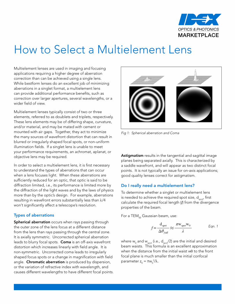
Spherical aberration occurs when rays passing through the outer zone of the lens focus at a different distance from the lens than rays passing through the central zone. It is axially symmetric. Uncorrected spherical aberration leads to blurry focal spots. Coma is an off-axis wavefront distortion which increases linearly with field angle. It is non-symmetric. Uncorrected coma leads to irregularly shaped focus spots or a change in magnification with field angle. Chromatic aberration is produced by dispersion, or the variation of refractive index with wavelength, and causes different wavelengths to have different focal points.
Astigmatism results in the tangential and sagittal image planes being separated axially. This is characterized by a saddle wavefront, and will appear as two distinct focal points. It is not typically an issue for on-axis applications; good quality lenses correct for astigmatism.
Do I really need a multielement lens?
To determine whether a singlet or multielement lens is needed to achieve the required spot size, dspot, first calculate the required focal length (f) from the divergence properties of the beam.
For a TEM00 Gaussian beam, use:
where w0 and wspot (i.e., dspot/2) are the initial and desired beam waists. This formula is an excellent approximation when the distance from the initial waist w0 to the front focal plane is much smaller than the initial confocal parameter z0 = πw0
2/λ.
How to Select a Multielement Lens
Fig 1: Spherical aberration and Coma
Eqn. 1

2 | IDEX Optics & Photonics Marketplace www.marketplace.idexop.com
Using f/# = f/d0, we obtain the condition:
To achieve diffraction-limited focusing, the f/# has to be greater, or the speed of the single element lens “slower” than this expression containing the focal length. As an example, see the figure below. It shows the limiting f/# for diffraction-limited focusing for a plano-convex fused silica lens at λ = 514.5 nm.
Aplanats
Aplanatic lenses are designed to be free of the two largest sources of aberration for monochromatic light: spherical aberration and coma. Together, these two aberrations distort the transmitted wavefront through the lens and cause the focal spot to become irregularly shaped and/or blurred. By correcting spherical aberration and coma, aplanats exhibit essentially diffraction-limited performance over their full aperture, and minimize focal spot size.
Aplanats are essential when tight control of the image and/or focal spot size at a single wavelength is critical to overall system performance and functionality. Applications include nonlinear optics experiments, laser beam expanders and collimators, interferometers, beam
For a non-diffraction-limited laser beam, use:
where Δθfull is the measured or manufacturer-specified full angle divergence.
For a uniform incident collimated beam truncated by an aperture d0, where diffraction limited focusing is required, use:
,
where the diffraction limit is estimated by the first minimum of the Airy diffraction pattern in the focal plane.
Next, calculate the blurred focal spot for a singlet lens due to the spherical aberration (Third Order aberration theory), using the shape factor (K), index of refraction (n), and incident beam diameter (d0):
,
For a properly oriented plano-convex lens of index n = 1.5, the bracketed factor is 0.073.
If the blurred focal spot size is greater than or equal to the desired spot size, a multielement lens is required to achieve the desired spot size. The next lens selection rule is based on blur as a result of spherical aberration compared with blur due to diffraction. It can also be formulated as a limiting f/#.
Fig 2: Limiting f/# for diffraction limited focusing for a plano-convex fused silica lens at λ=514.5 nm
Eqn. 2
Eqn. 3
Eqn. 4
Eqn. 5
Eqn. 6
Eqn. 7
Eqn. 8
Eqn. 9
Eqn. 10
IDEX Optics & Photonics Marketplace www.marketplace.idexop.com | 3
handling systems, material ablation and cutting systems, fiber optic interfacing. They can maintain image quality throughout the beam path, critical in imaging of optical traps. They are used widely with fiber lasers in material processing and research due to their ability to generate more tightly focused beams, higher energy at the work surface, sharper images for marking, and finer cuts for micro-machining.
Depending on the overall performance criteria, aplanats can be designed using 2-3 lenses of the same or different materials, and can be air-spaced to increase damage threshold and minimize additional wavefront distortion induced by the cement between the glass surfaces. Use of high-energy antireflection coatings can allow an air-spaced fused silica lens to transmit greater than 98 – 99 % of the incoming light while still withstanding more than 30 J/cm2 of pulsed light at 1064 nm. Air spacing also allows for more flexibility in design, as adjacent surfaces do not need to have matching curvatures. Instead, each of the four to six surfaces can be optimized independently, and the air gap can be treated as an additional lens element in order to better reduce coma and spherical aberrations through the complete lens assembly. Bonded lens assemblies carry their own benefits, including increased mechanical strength, greater durability, and increased overall transmission as a result of fewer surface reflections which are produced by external surfaces.
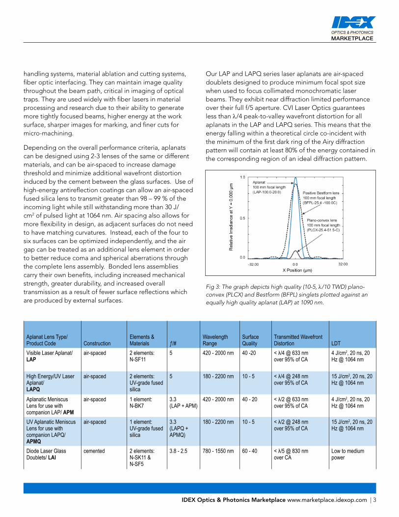
Our LAP and LAPQ series laser aplanats are air-spaced doublets designed to produce minimum focal spot size when used to focus collimated monochromatic laser beams. They exhibit near diffraction limited performance over their full f/5 aperture. CVI Laser Optics guarantees less than λ/4 peak-to-valley wavefront distortion for all aplanats in the LAP and LAPQ series. This means that the energy falling within a theoretical circle co-incident with the minimum of the first dark ring of the Airy diffraction pattern will contain at least 80% of the energy contained in the corresponding region of an ideal diffraction pattern.
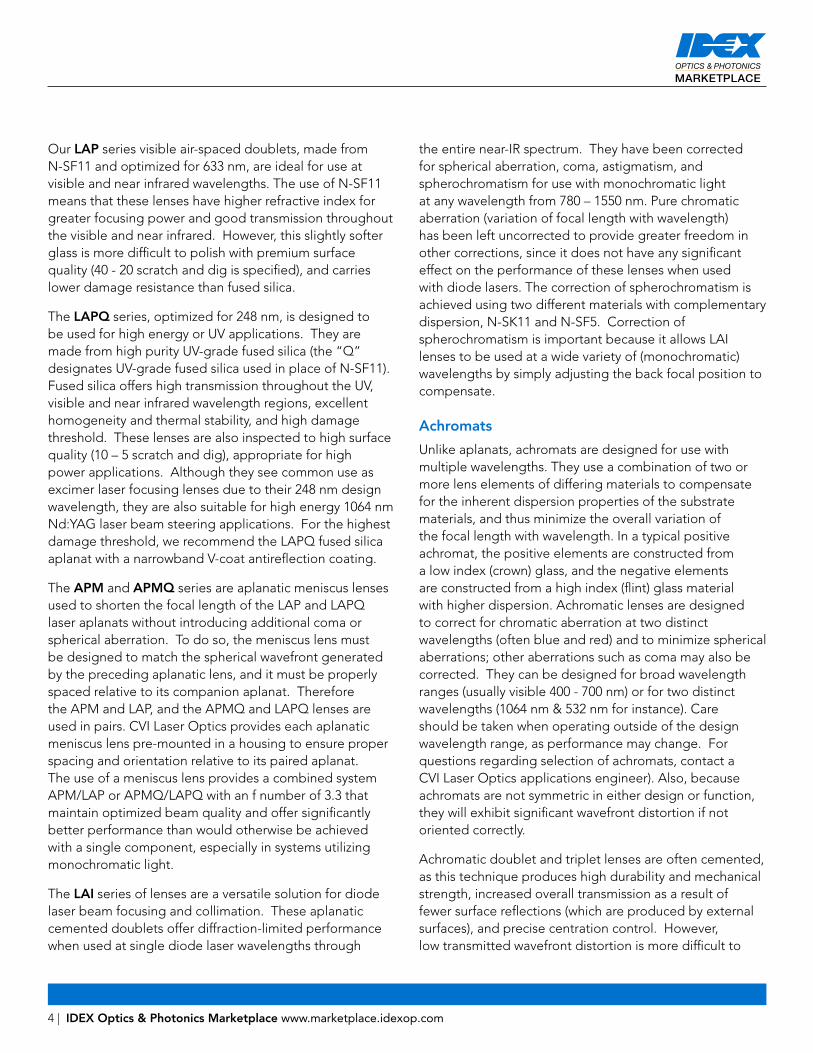
Aplanat Lens Type/Product Code Construction
Elements & Materials ƒ/#
Wavelength Range
Surface Quality
Transmitted Wavefront Distortion LDT
Visible Laser Aplanat/ LAP
air-spaced 2 elements: N-SF11
5 420 - 2000 nm 40 -20 < λ/4 @ 633 nm over 95% of CA
4 J/cm2, 20 ns, 20 Hz @ 1064 nm
High Energy/UV Laser Aplanat/ LAPQ
air-spaced 2 elements: UV-grade fused silica
5 180 - 2200 nm 10 - 5 < λ/4 @ 248 nm over 95% of CA
15 J/cm2, 20 ns, 20 Hz @ 1064 nm
Aplanatic Meniscus Lens for use with companion LAP/ APM
air-spaced 1 element: N-BK7
3.3 (LAP + APM)
420 - 2000 nm 40 - 20 < λ/2 @ 633 nm over 95% of CA
4 J/cm2, 20 ns, 20 Hz @ 1064 nm
UV Aplanatic Meniscus Lens for use with companion LAPQ/ APMQ
air-spaced 1 element: UV-grade fused silica
3.3 (LAPQ + APMQ)
180 - 2200 nm 10 - 5 < λ/2 @ 248 nm over 95% of CA
15 J/cm2, 20 ns, 20 Hz @ 1064 nm
Diode Laser Glass Doublets/ LAI
cemented 2 elements: N-SK11 & N-SF5
3.8 - 2.5 780 - 1550 nm 60 - 40 < λ/5 @ 830 nm over CA
Low to medium power
Fig 3: The graph depicts high quality (10-5, λ/10 TWD) plano-convex (PLCX) and Bestform (BFPL) singlets plotted against an equally high quality aplanat (LAP) at 1090 nm.
4 | IDEX Optics & Photonics Marketplace www.marketplace.idexop.com
Our LAP series visible air-spaced doublets, made from N-SF11 and optimized for 633 nm, are ideal for use at visible and near infrared wavelengths. The use of N-SF11 means that these lenses have higher refractive index for greater focusing power and good transmission throughout the visible and near infrared. However, this slightly softer glass is more difficult to polish with premium surface quality (40 - 20 scratch and dig is specified), and carries lower damage resistance than fused silica.
The LAPQ series, optimized for 248 nm, is designed to be used for high energy or UV applications. They are made from high purity UV-grade fused silica (the “Q” designates UV-grade fused silica used in place of N-SF11). Fused silica offers high transmission throughout the UV, visible and near infrared wavelength regions, excellent homogeneity and thermal stability, and high damage threshold. These lenses are also inspected to high surface quality (10 – 5 scratch and dig), appropriate for high power applications. Although they see common use as excimer laser focusing lenses due to their 248 nm design wavelength, they are also suitable for high energy 1064 nm Nd:YAG laser beam steering applications. For the highest damage threshold, we recommend the LAPQ fused silica aplanat with a narrowband V-coat antireflection coating.
The APM and APMQ series are aplanatic meniscus lenses used to shorten the focal length of the LAP and LAPQ laser aplanats without introducing additional coma or spherical aberration. To do so, the meniscus lens must be designed to match the spherical wavefront generated by the preceding aplanatic lens, and it must be properly spaced relative to its companion aplanat. Therefore the APM and LAP, and the APMQ and LAPQ lenses are used in pairs. CVI Laser Optics provides each aplanatic meniscus lens pre-mounted in a housing to ensure proper spacing and orientation relative to its paired aplanat. The use of a meniscus lens provides a combined system APM/LAP or APMQ/LAPQ with an f number of 3.3 that maintain optimized beam quality and offer significantly better performance than would otherwise be achieved with a single component, especially in systems utilizing monochromatic light.
The LAI series of lenses are a versatile solution for diode laser beam focusing and collimation. These aplanatic cemented doublets offer diffraction-limited performance when used at single diode laser wavelengths through
the entire near-IR spectrum. They have been corrected for spherical aberration, coma, astigmatism, and spherochromatism for use with monochromatic light at any wavelength from 780 – 1550 nm. Pure chromatic aberration (variation of focal length with wavelength) has been left uncorrected to provide greater freedom in other corrections, since it does not have any significant effect on the performance of these lenses when used with diode lasers. The correction of spherochromatism is achieved using two different materials with complementary dispersion, N-SK11 and N-SF5. Correction of spherochromatism is important because it allows LAI lenses to be used at a wide variety of (monochromatic) wavelengths by simply adjusting the back focal position to compensate.
Achromats
Unlike aplanats, achromats are designed for use with multiple wavelengths. They use a combination of two or more lens elements of differing materials to compensate for the inherent dispersion properties of the substrate materials, and thus minimize the overall variation of the focal length with wavelength. In a typical positive achromat, the positive elements are constructed from a low index (crown) glass, and the negative elements are constructed from a high index (flint) glass material with higher dispersion. Achromatic lenses are designed to correct for chromatic aberration at two distinct wavelengths (often blue and red) and to minimize spherical aberrations; other aberrations such as coma may also be corrected. They can be designed for broad wavelength ranges (usually visible 400 - 700 nm) or for two distinct wavelengths (1064 nm & 532 nm for instance). Care should be taken when operating outside of the design wavelength range, as performance may change. For questions regarding selection of achromats, contact a CVI Laser Optics applications engineer). Also, because achromats are not symmetric in either design or function, they will exhibit significant wavefront distortion if not oriented correctly.
Achromatic doublet and triplet lenses are often cemented, as this technique produces high durability and mechanical strength, increased overall transmission as a result of fewer surface reflections (which are produced by external surfaces), and precise centration control. However, low transmitted wavefront distortion is more difficult to

IDEX Optics & Photonics Marketplace www.marketplace.idexop.com | 5
achieve, and laser damage threshold and power handling are severely compromised by the cement layer. With air-spaced achromats, high damage threshold and low transmitted wavefront distortion through the assembly can be achieved. As with aplanats, air-spacing the components also allows for more flexibility in the design which in turn leads to even better color correction. This option is nevertheless more expensive because both sides of the components must be coated to minimize reflection losses, and extra mechanical parts are required. Achromats find use in broadband applications, including astronomical telescopes, color photomicrography, plasma spectroscopy, and biomedical instrumentation.
Our line of visible achromats includes three grades: standard, precision, and laser-grade, each suited to a different type of performance requirement. All are cemented doublets composed of complementary crown and flint glasses, computer optimized for infinite conjugate ratio and suitable for use with low to medium energy lasers. These achromats have been corrected for spherical aberration and coma, with the achromatization constraint slightly relaxed in favor of monochromatic aberration suppression, resulting in a superior achromatic
lens. (Precise focal length equality at the extreme design wavelengths is excessive and impairs overall performance.) These achromats therefore perform much better than a singlet lens for monochromatic applications at any visible wavelength.
Due to the superior imaging properties of CVI Laser Optics’ visible achromats, there is often interest in using them outside the visible spectrum. When moving from the mid-visible to 1064 nm, you may observe a 0.5 – 1.0 % increase in focal length due to the several different glass combinations utilized in the series. A similar amount of variation in back focal length (ƒb) and secondary principal-point position can be expected.
Our LAO series standard 400 – 700 nm cemented achromats are well-suited to general-purpose imaging tasks and low-power laser beam manipulation. Surface accuracy is λ/4 to λ/2 over 90% of the diameter, and they are inspected to a minimum surface quality of 60-40 scratch and dig. Standard grade lenses are an economical solution for many applications, but lower surface accuracy impacts resolution. They are provided with a broadband, single layer MgF2 antireflection coating for 400 – 700 nm.
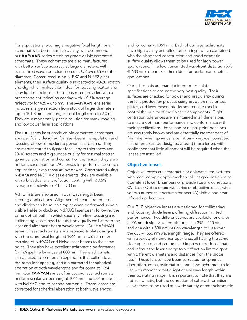
Acromat Lens Type/Product Code Construction
Elements & Materials ƒ/#
Wavelength Range
Surface Quality Surface Accuracy LDT
Laser-Grade Visible Cemented Achromat/ LAL
cemented 2 elements: N-BAK4 & N-SF10
3 - 2.2 415 - 700 nm 20 - 10 < λ/2 (f/# < 3.0) < λ/4 (f/# ≥ 3.0) @ 546.1 nm over CA
Low to medium power
Precision-Grade Visible Cemented Achromat AAP/AAN
cemented 2 elements: N-BK7 & N-SF2
46.3 - 4.6 425 - 675 nm 40 -20 TWD < λ/2 p-v @ 633 nm over CA
Low to medium power
Standard 400 - 700 nm Cemented Achromat LAO
cemented 2 elements: N-BAK4, -SF10, N-BK7, N-SF5, N-SF8, N-BAK1, or N-SK11
15.6 - 1.7 400 - 700 nm 60 - 40 < λ/2 (f/# < 3.0) < λ/4 (f/# ≥ 3.0) @ 633 nm over CA
Low to medium power
1064/633 nm Air-Spaced Laser Achromat HAP/HAN
air-spaced 3 elements: N-BK7 & N-SF11
5 633 - 1064 nm 40 -20 TWD < λ/2 p-v @ 633 nm over 95% of CA
4 J/cm2, 20 ns, 20 Hz @ 1064 nm
1064/532 nm Air-Spaced Laser Achromat YAP/YAN
air-spaced 3 elements: N-BK7 & N-SF11
5 532 nm & 1064 nm
40 -20 TWD < λ/2 p-v @ 633 nm over 95% of CA
4 J/cm2, 20 ns, 20 Hz @ 1064 nm
6 | IDEX Optics & Photonics Marketplace www.marketplace.idexop.com
For applications requiring a negative focal length or an achromat with better surface quality, we recommend our AAP/AAN series precision grade visible cemented achromats. These achromats are also manufactured with better surface accuracy at large diameters, with transmitted wavefront distortion of ≤ λ/2 over 85% of the diameter. Constructed using N-BK7 and N-SF2 glass elements, their surface quality is inspected to 40-20 scratch and dig, which makes them ideal for reducing scatter and stray light reflections. These lenses are provided with a broadband antireflection coating with ≤ 0.5% average reflectivity for 425 – 675 nm. The AAP/AAN lens series includes a large selection from stock of larger diameters (up to 101.8 mm) and longer focal lengths (up to 2.0 m). They are a moderately-priced solution for many imaging and low power laser applications.
The LAL series laser grade visible cemented achromats are specifically designed for laser-beam manipulation and focusing of low to moderate power laser beams. They are manufactured to tighter focal length tolerances and 20-10 scratch and dig surface quality for minimal scatter, spherical aberration and coma. For this reason, they are a better choice than our LAO lenses for performance-critical applications, even those at low power. Constructed using N-BAK4 and N-SF10 glass elements, they are available with a broadband antireflection coating with ≤ 0.5% average reflectivity for 415 – 700 nm.
Achromats are also used in dual wavelength beam steering applications. Alignment of near infrared lasers and diodes can be much simpler when performed using a visible HeNe or doubled Nd:YAG laser beam following the same optical path, in which case any in-line focusing and collimating lenses need to function equally well at both the laser and alignment beam wavelengths. Our HAP/HAN series of laser achromats are air-spaced triplets designed with the same focal length at 1064 nm and 633 nm for focusing of Nd:YAG and HeNe laser beams to the same point. They also have excellent achromatic performance for Ti:Sapphire laser use at 800 nm. These achromats can be used to form beam expanders that collimate at the same lens spacing, and are corrected for spherical aberration at both wavelengths and for coma at 1064 nm. Our YAP/YAN series of air-spaced laser achromats perform similarly, operating at 1064 nm and 532 nm for use with Nd:YAG and its second harmonic. These lenses are corrected for spherical aberration at both wavelengths,
and for coma at 1064 nm. Each of our laser achromats have high quality antireflection coatings, which combined with the air-spaced construction and good cosmetic surface quality allows them to be used for high power applications. The low transmitted wavefront distortion (λ/2 @ 633 nm) also makes them ideal for performance-critical applications.
Our achromats are manufactured to test-plate specifications to ensure the very best quality. Their surfaces are checked for power and irregularity during the lens production process using precision master test plates, and laser-based interferometers are used to control the quality of the finished components. Tight centration tolerances are maintained in all dimensions to ensure optimum performance and conformance with their specifications. Focal and principal-point positions are accurately known and are essentially independent of f-number when spherical aberration is very well corrected. Instruments can be designed around these lenses with confidence that little alignment will be required when the lenses are installed.
Objective lenses
Objective lenses are achromatic or aplanatic lens systems with more complex opto-mechanical designs, designed to operate at lower f/numbers or provide specific corrections. CVI Laser Optics offers two series of objective lenses with various numerical apertures for near-UV, visible and near-infrared applications.
Our GLC objective lenses are designed for collimating and focusing diode lasers, offering diffraction limited performance. Two different series are available: one with a 405 nm design wavelength for use at 395 – 415 nm, and one with a 830 nm design wavelength for use over the 633 – 1550 nm wavelength range. They are offered with a variety of numerical apertures, all having the same clear aperture, and can be used in pairs to both collimate and refocus the laser energy to a diffraction limited spot with different diameters and distances from the diode laser. These lenses have been corrected for spherical aberration, coma, astigmatism, and spherochromatism for use with monochromatic light at any wavelength within their operating range. It is important to note that they are not achromatic, but the correction of spherochromatism allows them to be used at a wide variety of monochromatic
IDEX Optics & Photonics Marketplace www.marketplace.idexop.com | 7
wavelengths by simply adjusting the back focal position. In addition to diode lasers, these lenses can be used with other narrow-band laser sources, or for fiber optic coupling and collimating.
Our OAS standard microscope objectives are achromatic within the visible wavelength range, and are designed for a 160 mm tube length with standard RMS mounting thread. They are “parfocal”, which means that they have the same distance from the objective mounting flange to the object, allowing objectives to be easily interchanged with a minimum of refocusing. Available in numerical apertures from 0.12 to 0.65, they are also useful for focusing lower power visible lasers, and for constructing spatial filters and beam expanders. These objectives are color-corrected for viewing and visual inspection. When choosing an objective, keep in mind that an objective with a larger NA gathers more light and has higher resolution but provides a smaller depth of field and shorter working distance, and costs more than an objective with a smaller NA.
F-Theta lenses
Laser scanning systems using galvanometer mirrors or rotating polygons require special scanning lenses to create flat (planar) imaging fields. Although standard scanning lenses provide a flat field, the distance traveled by the scanned spot is not a linear function of the deflection angle, requiring the use of complex electronic correction algorithms within the drive electronics. F-theta lenses improve on this by adding extra elements and a precise amount of barrel distortion to the scanning lens, thus resulting in a spot position that is directly proportional to the scan angle. Our FTL series of F-theta lenses are designed for high power use at 1064 nm, and offer a small and uniform spot size over the entire scan field as well as exceptionally high scan linearity. These lenses are ideal for most marking, writing, and photoresist exposure applications, but may cause angled holes and chamfers in cutting and drilling applications. Telecentric F-theta lenses should be used for these critical applications. In addition to industrial material processing, F-theta lenses are used in science and research, as well as in medical and biotechnology applications like confocal microscopy and ophthalmology.
When selecting an off-the-shelf F-theta scanning lens or specifying a custom lens, there are many parameters
to consider, the most important being the operating wavelength, focused spot size, scan field dimension, and the need for telecentricity. These factors place constraints on parameters like entrance pupil diameter and location, as well as deflection angles and focal length selection, and determine input beam diameter and galvanometer mirror locations and size. Other parameters to be considered are the laser damage threshold, front and back working distance, scan lens size and mounting interface.
Laser beam expanders
Beam expanders are optical systems used to increase the diameter of a beam, or to decrease it (when used in reverse). Since the product of beam diameter and divergence of a laser beam is constant, increasing the beam diameter will reduce the divergence of the beam by the same factor. CVI Laser Optics offers several types of beam expanders, all based on a compact Galilean design composed of a diverging lens group and a collimating lens group. The use of a Galilean design has several advantages: no internal focus, a more compact housing design, and the design flexibility to have the second lens group effectively cancel spherical aberrations induced by the first. As the spacing between the two lens groups is adjusted, the degree of collimation is varied continuously. Beam expanders find use in laser communications and distant target illumination applications. In addition, because an expanded laser beam can be focused to a much smaller spot size than an unexpanded one, beam expanders are also used extensively in light focusing applications.
Our LBX standard beam expanders are a cost-effective option for broadband applications using low power visible lasers. They work well to expand a laser beam for uniform illumination of a large area, with wavefront distortion of 1λ or less peak to valley at 633 nm. They use a cemented construction, making them suitable for use only with low to medium energy lasers.
If working at higher power, or at UV or near infrared wavelengths, consider one of our high energy beam expanders. These air-spaced assemblies are manufactured using high quality UV-grade fused silica bestform lenses. Fused silica offers superior transmission in the UV, excellent homogeneity and thermal stability, and higher damage threshold than N-BK7. All possess a transmitted

8 | IDEX Optics & Photonics Marketplace www.marketplace.idexop.com
wavefront distortion of λ/2 over 85% of the clear aperture, and are coated with low loss, high energy AR coatings at user specified wavelengths. The BXUV series has been designed for 266 nm, and the HEBX for 1064 nm, giving options for high power laser use at UV through NIR wavelengths. We also offer a line of dual wavelength beam expanders for more demanding applications using Nd:YAG lasers. The DWBX series includes 1064/532 and 1064/633 nm beam expanders for use in beam alignment and research. Their Galilean design uses two high power AR-coated triplet lenses, and are corrected for chromatic and spherical aberrations at both design wavelengths, as well as for coma at 1064 nm. With better wavefront quality and achromatization than telescope objectives, these high quality beam expanders can be used to simultaneously expand Nd:YAG and doubled Nd:YAG beams, or to alter the diameter of a Ti:sapphire laser at 800 nm.
Shear plate collimation testers
A shear plate is a very simple interferometer, using interference between two wavefronts to generate a fringe pattern containing information about the wavefront of the incident beam. Shear plates can be used to adjust a laser collimation system, measure a wavefront’s radius of curvature, determine wavefront symmetry, measure the power of long focal length optics, and in some cases analyze wavefront aberrations.
Shear plates are thick, high quality optical flats, generally oriented at 45° to the test beam. Wavefronts reflecting from the front and back surfaces are said to be “laterally sheared”, i.e., offset with respect to one another due to the finite thickness of the plate. Interference occurs in the region where the wavefronts overlap, as shown in the diagram. CVI Laser Optics uses high quality wedged N-BK7 shear plates with λ/20 surface flatness (at 633 nm) to produce a gradual path difference between the front and back surface reflections. Consequently, a parallel beam of light produces a linear fringe pattern where the reflections overlap. Our SPM shear plate collimation testers use shear plates mounted in a housing containing a viewing screen to simplify visualization and measurements of the fringe pattern.
A perfectly collimated beam will produce equally spaced fringes parallel to the reference line on the viewing screen. A beam that is reasonably close to collimation will still produce equally spaced fringes, but they will be rotated with respect to the reference line. The wavefront radius of curvature of the beam can be calculated using R = sδ/(λsinθ), where s is the shear distance, δ is the fringe spacing, and θ is the angle of rotation relative to the reference line. For CVI Laser Optics shear plate modules, a convergent beam will produce a clockwise rotation, while a divergent beam will produce a counter-clockwise rotation when viewed on the display screen. If the beam being tested overfills the viewing screen, it is acceptable to temporarily reduce the diameter of the beam with an iris to measure the shear distance, as s is not dependent on the beam diameter.
Fig 4: Shear plate collimation tester
Fig 5: Measurable quantities needed in order to use the shear equation.
IDEX Optics & Photonics Marketplace www.marketplace.idexop.com | 9
CVI Laser Optics’ line of collimation testers consists of three sizes. Modules with clear apertures 25, 50 and 85 mm are available. In each case the wedge angle is chosen such that a collimated 632.8 nm laser beam filling the entire aperture will display approximately six fringes across the screen (more fringes will be visible for shorter wavelengths). A minimum of one fringe is required in the interference region to adjust the collimation. Since the size of the interference region is dependent on the shear distance, CVI Laser Optics shear plates require a minimum beam diameter of 5, 10 and 15 mm respectively.
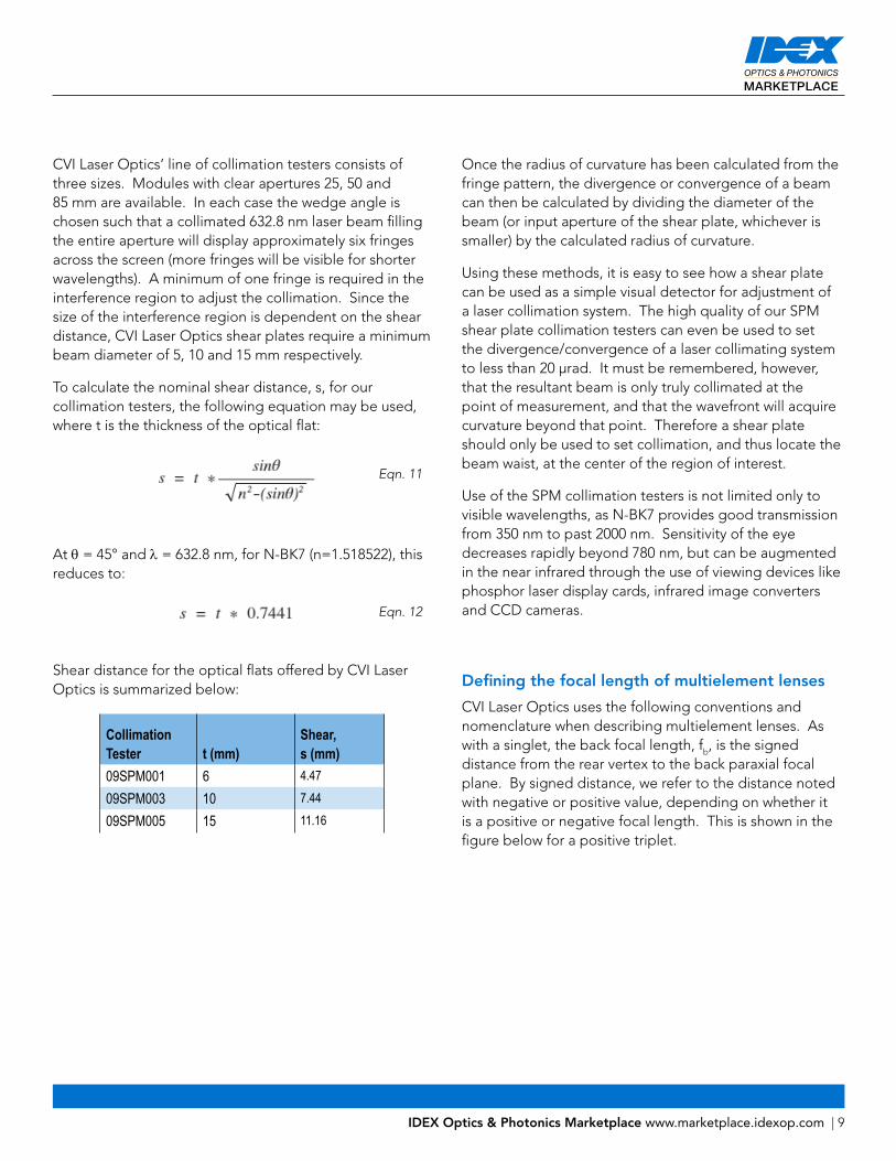
To calculate the nominal shear distance, s, for our collimation testers, the following equation may be used, where t is the thickness of the optical flat:
At θ = 45° and λ = 632.8 nm, for N-BK7 (n=1.518522), this reduces to:
Shear distance for the optical flats offered by CVI Laser Optics is summarized below:
Collimation Tester t (mm)
Shear, s (mm)
09SPM001 6 4.47
09SPM003 10 7.44
09SPM005 15 11.16
Once the radius of curvature has been calculated from the fringe pattern, the divergence or convergence of a beam can then be calculated by dividing the diameter of the beam (or input aperture of the shear plate, whichever is smaller) by the calculated radius of curvature.
Using these methods, it is easy to see how a shear plate can be used as a simple visual detector for adjustment of a laser collimation system. The high quality of our SPM shear plate collimation testers can even be used to set the divergence/convergence of a laser collimating system to less than 20 µrad. It must be remembered, however, that the resultant beam is only truly collimated at the point of measurement, and that the wavefront will acquire curvature beyond that point. Therefore a shear plate should only be used to set collimation, and thus locate the beam waist, at the center of the region of interest.
Use of the SPM collimation testers is not limited only to visible wavelengths, as N-BK7 provides good transmission from 350 nm to past 2000 nm. Sensitivity of the eye decreases rapidly beyond 780 nm, but can be augmented in the near infrared through the use of viewing devices like phosphor laser display cards, infrared image converters and CCD cameras.
Defining the focal length of multielement lenses
CVI Laser Optics uses the following conventions and nomenclature when describing multielement lenses. As with a singlet, the back focal length, fb, is the signed distance from the rear vertex to the back paraxial focal plane. By signed distance, we refer to the distance noted with negative or positive value, depending on whether it is a positive or negative focal length. This is shown in the figure below for a positive triplet.
Eqn. 11
Eqn. 12

10 | IDEX Optics & Photonics Marketplace www.marketplace.idexop.com
The advantage of a consistent formalism is evident in the construction of a Galilean beam expander, shown below. Here, both the negative and positive elements will have a common focus, as shown.
To determine the spacing of the elements, distances strictly referenced to optical surfaces are required. The logical choice is to use the back focal lengths, thus we have:
d = (ƒb)positive + (ƒb)negative = |(ƒb)positive| − |(ƒb)negative|
It may be noted that the equation above is not actually consistent with our definitions when the direction of the light rays is considered. Strictly speaking, it is the front focal distance of the positive element that is required in the formula above. However, it is customary to list the back focal length of a lens as the distance from its last element to the focal plane when the lens is properly oriented for focusing a collimated beam from left to right. So, to design a system using lens tabulated values, keep in mind the orientation conventions used in the descriptions of the individual component lenses.
For a negative lens, ƒb is negative and is calculated using the same rule. The back focal length is the distance from the back vertex to the (virtual) back paraxial focal plane. We have put absolute signs around ƒb in the figure below to emphasize this.
Fig 6: Definition of back focal length for a positive triple
Fig 7: Definition of back focal length for a negative lens
Fig 8: Back focal lengths in a Galilean beam expander
Eqn. 13

IDEX Optics & Photonics Marketplace www.marketplace.idexop.com | 11
The working distance (WD) of elements in housings is provided in the product specifications. The working distance specifies the distance from the focal plane to a mechanical reference surface; here it is the housing edge closest to the focal plane. This is shown schematically in the figure below:
CVI Laser Optics aplanat marking conventions
Making the final decision
Selecting the right multielement lens or lens assembly involves identifying and quantifying the degree and type of aberrations that can be tolerated by the system, balanced by the wavelength requirements. If working at a single wavelength or over a narrow range, it is important to look equally at our achromats, aplanats and objectives lenses to find the best solution, as each particular series of lenses offers subtle differences in how achromatization is balanced vs. spherical aberration and coma correction or vice versa. Thought should also be given to the required specifications for the lens assembly. This will depend on the application, but performance factors to consider include laser damage threshold, degree of scatter, wavefront distortion quality, and focal length tolerance.
Most of CVI Laser Optics multielement lens design prescriptions are available in many of the commercially available optical design software packages, such as Zemax, to facilitate computer analysis. If one of our catalog multielement lenses is unable to fulfill your requirements, please contact us to discuss a custom solution.
Fig 9: Working distance of elements in housings
12 | IDEX Optics & Photonics Marketplace www.marketplace.idexop.com
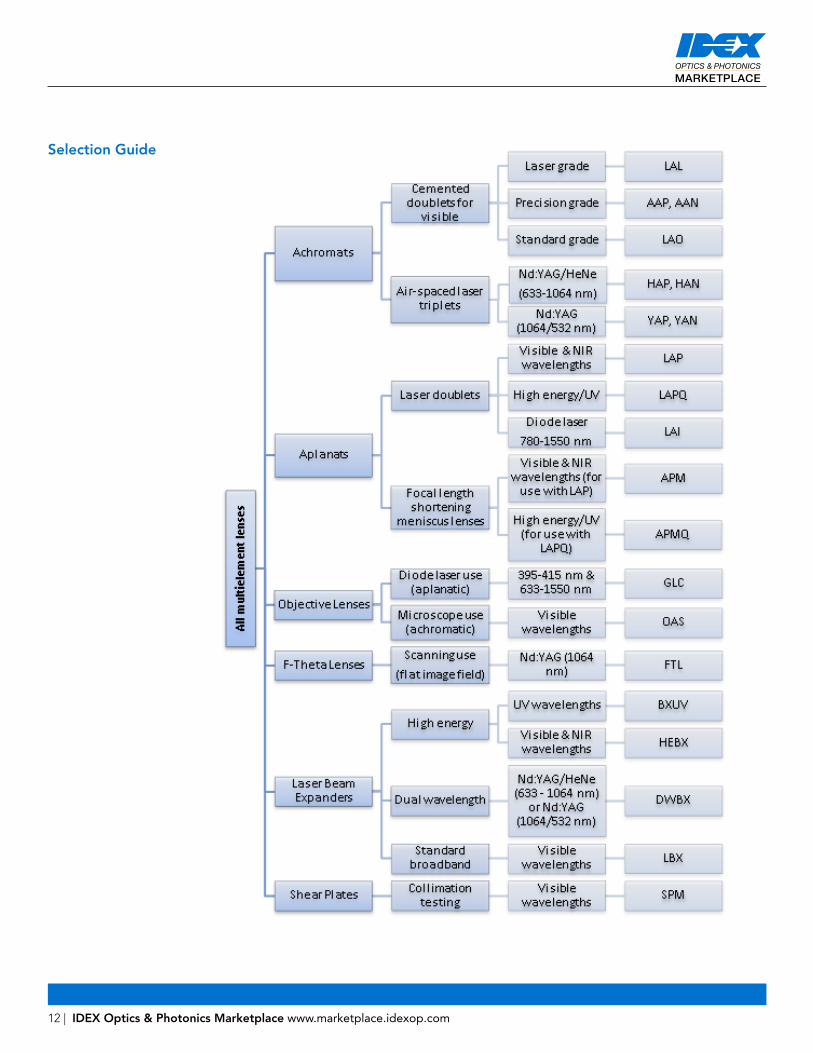
Selection Guide