how to use digital key pad (option) - industrial.panasonic.com · as "reading a parameter from...
TRANSCRIPT

38 39
Name of each part and how to setup• What can be done by Digital key pad
• Monitoring of rotation speed (actual speed) and load factor, etc. (Rotation speed can be displayed being multiplied by the factor set by parameter 47 and 48.)
• Display detail of trip, and trip history. Trip reset by pressing and .
• Parameter setting, initialization, and copying function.• Start and stop of motor by , switch (Set-
ting of parameter “ 30 Run command selection” is required.)
• Name of each part
5-digit LED Displays rotation speed (actual speed), commanded speed, trip history, setting of parameter, and the like.
2-digit LED
Displays the number of parameter (in editing parameter).Displays the rotation direction in operation. Displays when the motor is stopped.(CCW as viewed from the output shaft of motor ... and CW... )Rotation direction of gear head output shaft may be reversed for some gear reduction ratio when gear head is incorporated. Please refer to the table of the permissible torque (P.28).
switch
Switch for changing monitor mode. Whenever this switch is pressed, the mode changes in this sequence: Rotation speed (actual speed) → Internal DC voltage (voltage of smoothing capacitor of power supply) → Load factor → torque reference →Commanded speed → Rotation speed (actual speed) → ...** When you press this switch in the parameter setting mode, setting is stored.
switch This switch is for changing parameter number mode and parameter setting mode, and for saved parameter setting.
switchThis switch enables selection of parameter, and setting and changing of contents.When the motor is tripped, pressing and at the same time enables reset of trip.
switch
This switch is for instruction of operation. (Only when “ 30 Run command selection” is )• See “ 33 I1/ I2 function selection” (2) on P.57 for rotation direction.• Disconnecting the Digital key pad while operating with switch will stop the
operation.
switchThis switch is for instruction of stopping. (Only when “ 30 Run command selection” is )
How to use Digital key pad (option)
5-digit LED
2-digit LED
RUN switchMODE switchSTOP switchDATA SET switch
switch
• Description
Monitor mode
Displays rotation speed (actual speed), setting speed, internal DC voltage, load factor, and torque reference on 5-digit LED. This mode is set when power is turned on. Control changes to this mode when switch is pressed in parameter number mode, parameter setting mode.
Parameter number mode
Displays a parameter number (00 to F0) in blinking. Control changes to this mode when switch is pressed in monitor mode. Parameter number can be changed and selected by and switch.
Parameter setting mode
Displays the detail of parameter (setting) in blinking. Change setting by and switch.When switch or switch is pressed after change of setting, it is saved in EEPROM.
* Displays rotation speed r/min in normal monitor mode. Displays torque reference and load factor assuming the rated motor torque at 100%.
* Display is just a guide. Do not use the Digital key pad for a measuring instrument.

40 41
Operating Instruction
• When or is pressed in monitor mode, detail of “ 00 Internal speed (0-th speed)” is displayed in blinking, and speed setting can be changed by and .
When “ 31 Speed command selection” is , the motor speed also changes following the speed setting if the motor is running.
Data is stored only when DATASET switch is pressed. If the power is turned off with-
out storage, setting data will return.
Rotation speed
Internal DC voltage
Turn onpower. Monitor mode
Parameternumbermode
Parametersettingmode
Press
Press
DATASET
PressDATASET
DATASET
Press
Stor
age
Stor
age
DATASET
MODE
MODE
Load factor
FlashingMODE
MODE
Torque reference
Only“00”
MODE
Speed setting
FlashingMODE
PressMODE
MODE• Press switch for changing display.
• 2-digil LED blinks and allows selection of parameter number.
Internal speed (0-thspeed) can be directlyset by andin monitor mode.
Flashing
FlashingFlashing
FlashingFlashing
Change (select) a parameter number by or .
Change (select) a parameter value by or .
• 5-digit LED blinks and allows change of parameter value.
When switch or switch is pressed in parameter setting mode, data is stored.
MODE
Test run (Digital key pad)Inspection prior to test run/ Test run
Inspection prior to test run(1) Make sure that all wiring is correct.(2) Make sure that input power supply conforms to rating.
Test runTest run procedure by the Digital key pad is as follows: An example is introduced here where the motor runs CW at 1800 r/min with the Digital key pad. (1) Be sure to first perform the work below for safety. Separate the motor from machine or equipment, and make sure that the motor alone
can be operated. (2) Then turn on power and follow the step below for test run.
Description of operation
Digital key padSwitch LED display
[1] Turn on power
LED表示
LED表示
点滅
点滅
点滅
点滅
点滅
点滅
点滅
点滅
点滅
点滅
点滅
全点灯
全点灯
全点灯
全点灯
全点灯
全点灯
[2] Change of initial setting (Change the choice of operation instruction from I1/ I2 to the Digital key pad
.)
Press
Flashing FlashingPress several times to choose parameter 30.
Press
Flashing Flashing
Press to change parameter value.
Store by .
Setting change warning is issued because setting of operation instruction has been changed.
LED表示
LED表示
点滅
点滅
点滅
点滅
点滅
点滅
点滅
点滅
点滅
点滅
点滅
全点灯
全点灯
全点灯
全点灯
全点灯
全点灯
[3] Trip reset Press and at the same time.
LED表示
LED表示
点滅
点滅
点滅
点滅
点滅
点滅
点滅
点滅
点滅
点滅
点滅
全点灯
全点灯
全点灯
全点灯
全点灯
全点灯
42 43
Description of operation
Digital key padSwitch LED display
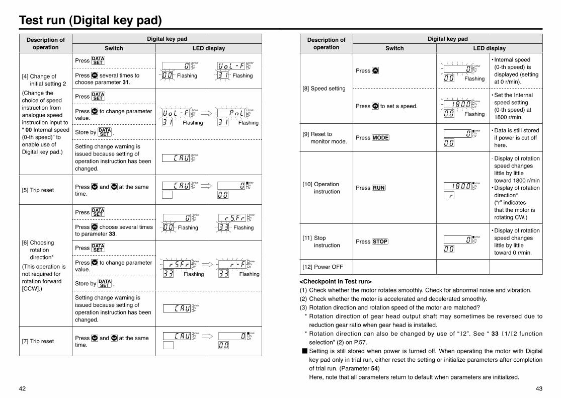
[8] Speed setting
Press Flashing
• Internal speed (0-th speed) is displayed (setting at 0 r/min).
Press to set a speed.Flashing
• Set the Internal speed setting
(0-th speed) at 1800 r/min.
[9] Reset to monitor mode. Press
LED表示
LED表示
点滅
点滅
点滅
点滅
点滅
点滅
点滅
点滅
点滅
点滅
点滅
全点灯
全点灯
全点灯
全点灯
全点灯
全点灯
• Data is still stored if power is cut off here.
[10] Operation instruction Press
LED表示
LED表示
点滅
点滅
点滅
点滅
点滅
点滅
点滅
点滅
点滅
点滅
点滅
全点灯
全点灯
全点灯
全点灯
全点灯
全点灯
・Display of rotation speed changes little by little toward 1800 r/min
• Display of rotation direction*
(“r” indicates that the motor is rotating CW.)
[11] Stop instruction Press
LED表示
LED表示
点滅
点滅
点滅
点滅
点滅
点滅
点滅
点滅
点滅
点滅
点滅
全点灯
全点灯
全点灯
全点灯
全点灯
全点灯
• Display of rotation speed changes little by little toward 0 r/min.
[12] Power OFF
<Checkpoint in Test run>(1) Check whether the motor rotates smoothly. Check for abnormal noise and vibration. (2) Check whether the motor is accelerated and decelerated smoothly. (3) Rotation direction and rotation speed of the motor are matched? * Rotation direction of gear head output shaft may sometimes be reversed due to
reduction gear ratio when gear head is installed. * Rotation direction can also be changed by use of “ I2”. See “ 33 I1/ I2 function
selection” (2) on P.57. ■ Setting is still stored when power is turned off. When operating the motor with Digital
key pad only in trial run, either reset the setting or initialize parameters after completion of trial run. (Parameter 54)
Here, note that all parameters return to default when parameters are initialized.
Test run (Digital key pad)Description of
operationDigital key pad
Switch LED display
[4] Change of initial setting 2(Change the choice of speed instruction from analogue speed instruction input to “ 00 Internal speed (0-th speed)” to enable use of Digital key pad.)
Press
Flashing FlashingPress several times to choose parameter 31.
Press
FlashingFlashing
Press to change parameter value.
Store by .
Setting change warning is issued because setting of operation instruction has been changed.
LED表示
LED表示
点滅
点滅
点滅
点滅
点滅
点滅
点滅
点滅
点滅
点滅
点滅
全点灯
全点灯
全点灯
全点灯
全点灯
全点灯
[5] Trip reset Press and at the same time.
LED表示
LED表示
点滅
点滅
点滅
点滅
点滅
点滅
点滅
点滅
点滅
点滅
点滅
全点灯
全点灯
全点灯
全点灯
全点灯
全点灯
[6] Choosing rotation direction* (This operation is not required for rotation forward [CCW].)
Press
Flashing FlashingPress choose several times to parameter 33.
Press
Flashing Flashing
Press to change parameter value.
Store by .
Setting change warning is issued because setting of operation instruction has been changed.
LED表示
LED表示
点滅
点滅
点滅
点滅
点滅
点滅
点滅
点滅
点滅
点滅
点滅
全点灯
全点灯
全点灯
全点灯
全点灯
全点灯
[7] Trip reset Press and at the same time.
LED表示
LED表示
点滅
点滅
点滅
点滅
点滅
点滅
点滅
点滅
点滅
点滅
点滅
全点灯
全点灯
全点灯
全点灯
全点灯
全点灯

44 45
1. Reading a parameter value from brushless amplifier to the Digital key pad.• Once parameters are read into the console, their details are stored in the Digital key pad.
Description of operation
Digital key padSwitch LED display
[1] Turn on power
LED表示
LED表示
点滅
点滅
点滅
点滅
点滅
点滅
点滅
点滅
点滅
点滅
点滅
全点灯
全点灯
全点灯
全点灯
全点灯
全点灯
[2] Call “ 57 parameter copy”
Press
Flashing
Parametervalue
FlashingHold down to choose parameter 57.
[3] Choose reading a param-eter into the Digital key pad.
Press
Flashing FlashingPress twice to choose .
[4] Read a parameter into the Digital key pad.
Press DATA for 1 second while holdingdown .
Flashing→Slow flashing(once per second)
[5] Wait about 30 seconds.
LED表示
LED表示
点滅
点滅
点滅
点滅
点滅
点滅
点滅
点滅
点滅
点滅
点滅
全点灯
全点灯
全点灯
全点灯
全点灯
全点灯
[6] Reading of parameter into the Digital key pad completed
Press
LED表示
LED表示
点滅
点滅
点滅
点滅
点滅
点滅
点滅
点滅
点滅
点滅
点滅
全点灯
全点灯
全点灯
全点灯
全点灯
全点灯
2. Copy a parameter value saved in the Digital key pad onto the brushless amplifier.
Description of operation
Digital key padSwitch LED display
Turn on power. Call “ 57 parameter copy”. (Same operation as 1. [1] and [2])
[1] Choose writing a parameter to the brushless amplifier.
Press
Flashing FlashingPress three times tochoose .
[2] Write a parameter to the brushless amplifier.
Press for 1 second while holding down .
Flashing→Slow flashing(once per second)
[3] Wait about 10 seconds.
LED表示
LED表示
点滅
点滅
点滅
点滅
点滅
点滅
点滅
点滅
点滅
点滅
点滅
全点灯
全点灯
全点灯
全点灯
全点灯
全点灯
[4] Completion of writing a parameter from the Digital key pad to the brushless amplifier.
LED表示
LED表示
点滅
点滅
点滅
点滅
点滅
点滅
点滅
点滅
点滅
点滅
点滅
全点灯
全点灯
全点灯
全点灯
全点灯
全点灯
[5] Reset to monitor mode.
Press and at the same time for clear trip.
LED表示
LED表示
点滅
点滅
点滅
点滅
点滅
点滅
点滅
点滅
点滅
点滅
点滅
全点灯
全点灯
全点灯
全点灯
全点灯
全点灯
Error while copying a parameter
: Data is abnormal while copying.→ Press switch for clearing, and then copy data again. If data is still abnormal, initialize the Digital key pad and retry.
: Copy error→ This error occurs in an attempt to copy data between products of different function. Press
switch for clear. Parameters can be copied between the same models, but parameters should be copied between the same output in principle because gain setting is different.
How to copy parameter

46 47
How to copy parameter3. Initializing of data of Digital key pad.
• When any trouble occurs during copying, it can be often solved by initializing the Digital key pad. (Stored data is cleared by initializing.)
Description of operation
Digital key padSwitch LED display
Turn on power and call “ 57 parameter copy”. (Same operation as 1. [1] and [2])
[1] Choose initialization of data
of Digital key pad.
Press
Flashing FlashingPress once and choose .
[2] Initialization of Digital key pad.
Press for 1 second while holding down .
Flashing→
LED display changes from flashing to continuous lighting during initializing operation.
Continuouslighting
[3] Wait about 30 seconds.
LED表示
LED表示
点滅
点滅
点滅
点滅
点滅
点滅
点滅
点滅
点滅
点滅
点滅
全点灯
全点灯
全点灯
全点灯
全点灯
全点灯
[4] Initializing of data of Digital key pad completed
Press
LED表示
LED表示
点滅
点滅
点滅
点滅
点滅
点滅
点滅
点滅
点滅
点滅
点滅
全点灯
全点灯
全点灯
全点灯
全点灯
全点灯
• Do not turn off power or disconnect the cable of Digital key pad during operation such as "Reading a parameter from the brushless amplifier to the Digital key pad", "Copying a parameter value stored in the Digital key pad to the brushless amplifier", and "Initializing the data of Digital key pad".
List of parameters (Default)Outline of parameters
Brushless amplifier of this series is equipped with various parameters for adjustment and setup to characteristics and functions. Amplifier in optimum condition for your running requirements.
Composition of parameters and list of default
Parameter No. Name of parameter
Parameter settingSetting range Minimum
unit Default Check*1
00 Internal speed(0-th speed)
0 to “ 3b Upper speed limit” 1 r/min
0
01 1st speed 3000
02 2nd speed 1200
03 3rd speed 600
04 4th speed 0
05 5th speed 0
06 6th speed 0
07 7th speed 0
10 1st acceleration timeto 3 sec :
3 sec to 30 sec :
30 sec to 300 sec :
0.01 to300 sec
Incremented by0.01 secondIncremented by0.1 secondIncremented by1 second
0.05
11 2nd acceleration time 2.00
12 1st deceleration time 0.05
13 2nd deceleration time 2.00
14 Acceleration mode selection
Linear S shape-1 *2
S shape-2 *215 Deceleration mode selection
16 Stop mode selection Free-run stop Speed reduction stop
17 Free-run waiting time 0.0 to 10.0 sec 0.1 sec 1.0
1A Velocity loop proportional gain 0 to 10000 1 400
1b Velocity loop integration gain 0 to 10000 1 500
*1 When parameter marked with “C” in the check column is changed and stored, the unit is tripped for safety. It is not allowed to change them while the motor is running.
*2 Select this when “ 31 Speed command selection” is (PANEL).