howto program the z80 sio - hp64000.net€¦ · preface the z80 sio is the most powerful i/o device...
TRANSCRIPT

Mario Blunk / electronics and IT engineeringBuchfinkenweg 599102 ErfurtGermany
cellular +49 (0)176 2904 5855office phone +49 (0361) 5189 618email [email protected] http://www.trainz.de
How To Program The Z80 Serial I/O (SIO) and CTCDocument Version 2.1
Date: 20100331
Contents 1 Terminal Mode....................................................................................................................2
1.1 Desired Communication Mechanism..........................................................................2 1.2 SIO Device Structure and external wiring...................................................................3
1.2.1 Wiring...................................................................................................................3 1.3 Programming...............................................................................................................5
1.3.1 Header..................................................................................................................5 1.3.2 Interrupt Vector Table...........................................................................................5 1.3.3 Initializing the SIO................................................................................................6 1.3.4 Initializing the CTC...............................................................................................7 1.3.5 Initializing the CPU..............................................................................................7 1.3.6 Hardware Flow Control........................................................................................8 1.3.7 Disabling SIO RXchannel...................................................................................8 1.3.8 Interrupt Service Routines...................................................................................9 1.3.9 Transmission of a character to the host.............................................................10
2 File Transfer Mode............................................................................................................11 2.1 Desired Communication Mechanism.........................................................................11 2.2 Programming.............................................................................................................12
2.2.1 Header................................................................................................................12 2.2.2 Interrupt Vector Table.........................................................................................12 2.2.3 Initializing the CTC.............................................................................................12 2.2.4 Initializing the CPU............................................................................................13 2.2.5 XModem File Transfer.......................................................................................13
2.2.5.1 Host triggered transfer and setup...............................................................13 2.2.5.2 Subroutines................................................................................................17
3 Z80 IC equivalents table...................................................................................................18 4 Useful Links......................................................................................................................19 5 Further Reading................................................................................................................19 6 Disclaimer.........................................................................................................................19
1
Preface
The Z80 SIO is the most powerful I/O device of the Z80 product family. The official ZiLOGdatasheet gives a good overall view of all the features of this device but lacks a tutorial like approach and programming examples in assembly language. This document aims to make the Z80 processor system popular again since a lot of valuable literature and expertise has vanished from the public because of more sophisticated processor architectures of the present.
Remarkably ZiLOG still produces the ICs of the Z80 family – since the late seventies ! Part one of this document describes how to program the SIO so that it communicates with a PC in asynchronous terminal mode whereas part two focuses on the block transfer mode used for file transmission. Also slightly touched in this document is the CTC programming and implementation of an interrupt mechanism.
There is no special focus on hardware issues like device selection, pin characteristics or ratings. Please refer to the official ZiLOG datasheets at www.zilog.com or www.z80.info .
The code examples shown here provide by far not the best performance and robustness. Therefore I appreciate every hint or critics to improve the quality of this document.
1 Terminal Mode
1.1 Desired Communication MechanismWe want to program the SIO for asynchronous RS232 terminal mode with these parameters:
Baudrate: 9600 Baud/sec
Stopbits: 1
Startbits: 1
Character length: 8 bit
Parity: none
In terminal mode the host computer (in our case the PC with any terminal program like Minicom or Hyper Terminal and an RS232 interface) communicates with the client (the Z80SIO) character based via a so called NullModemCable. The host transmits one or more characters to the client, whereupon the client echoes this character back to the host and processes it. The host displays the echoed character on its screen. If the host does not “hear” the echoed character the communication is faulty.
2
Special attention is to be paid to the flow control scheme which is hardware based. In general this is called “RTSCTS” or just “hardware flow control”. This method allows transmission of all 8bitcharacters (so called binary mode) and prevents overrunning of one of the peers in case on of them is to slow. In this document I assume the host PC is much faster than the client.
The wiring of the null modem cable used here has following connections between its female 9 pin DSub connectors:
1 – 4 / 41 cross wired DTR and DCD
2 – 3 / 3 – 2 cross wired TxD and RxD
5 – 5 signal ground (GND)
7 – 8 / 8 – 7 cross wird RTC and CTS
9 – 9 ring indicator (RI, not used here)
1.2 SIO Device Structure and external wiringFigure 1 shows the block diagram of the device with the blocks and signals needed for our example outlined in red. Figure 2 shows the data paths within the SIO. Marked in red are the blocks we need for asynchronous mode.
1.2.1 WiringData and control: These are the Z80 bus signals D[7:0], A[1:0], /RD, /IOREQ,
/RESET, /CE and CLK.
Interrupt Control Lines: /M1, /INT connected to CPU, IEI and IEO daisy chained to other periphery
Serial Data: TxD and RxD going towards host computer1
Channel Clocks: TxCA and RxCA driven by CTC channel output TO0
Modem or other Controls: CTS, RTS, DTR, DCD used for hardware flow control
miscellaneous: /SYNC not used, pulled high by 10k resistor/Wait/Ready comes out of the device. It is to be connected to the WAITInput of the Z80CPU. By asserting this signal the SIO tells the CPU to wait until the SIO has completed a character transfer. For this example we do not make use of this connection.
1 Usually these signals are not connected directly to the host but via diver devices like MAX232, 1488, 1489 or similar level converters.
3

4
Figure 1: Block Diagram
Figure 2: Data Path

1.3 ProgrammingTree problems have to be solved: initializing the SIO, implementing the interrupt mechanism, echoing the received character, transmitting a character and turning on/off the SIO RXchannel in certain situations.
1.3.1 HeaderThe header show below defines the hardware addresses of the data and control port of your SIO and the address of your CTC channel 0. My hardware here uses the addresses 0x4, 0x6 and 0x0.
1.3.2 Interrupt Vector TableEvery time the SIO receives a character it requests an interrupt causing the CPU to jump to the memory address specified by the term RX_CHA_AVAILABLE. Special receive conditions like receiver buffer overrun cause a jump to location SPEC_RX_CONDITION.
5
Text 1: header
SIO_A_D equ 4hSIO_A_C equ 6hCH0 equ 0h
Text 2: SIO interrupt vector table
INT_VEC:org 0ChDEFW RX_CHA_AVAILABLEorg 0EhDEFW SPEC_RX_CONDITON

1.3.3 Initializing the SIOFirst we have to configure the SIO using the sequence shown in Text 3. For detailed information on the purpose of certain registers and control bits please read the SIO datasheet. We operate the SIO in interrupt mode “interrupt on all received characters”.
6
Text 3: configure the SIO
SIO_A_RESET:;set up TX and RX:ld a,00110000b ;write into WR0: error reset, select WR0out (SIO_A_C),A
ld a,018h ;write into WR0: channel resetout (SIO_A_C),A
ld a,004h ;write into WR0: select WR4out (SIO_A_C),Ald a,44h ;44h write into WR4: clkx16,1 stop bit, no parityout (SIO_A_C),A
ld a,005h ;write into WR0: select WR5out (SIO_A_C),Ald a,0E8h ;DTR active, TX 8bit, BREAK off, TX on, RTS inactiveout (SIO_A_C),A
ld a,01h ;write into WR0: select WR1out (SIO_B_C),Ald a,00000100b ;no interrupt in CH B, special RX condition affects vectout (SIO_B_C),A
ld a,02h ;write into WR0: select WR2out (SIO_B_C),Ald a,0h ;write into WR2: cmd line int vect (see int vec table)
;bits D3,D2,D1 are changed according to RX conditionout (SIO_B_C),A
ld a,01h ;write into WR0: select WR1out (SIO_A_C),Ald a,00011000b ;interrupt on all RX characters, parity is not a spec RX condition
;buffer overrun is a spec RX conditionout (SIO_A_C),A
SIO_A_EI:;enable SIO channel A RXld a,003h ;write into WR0: select WR3out (SIO_A_C),Ald a,0C1h ;RX 8bit, auto enable off, RX onout (SIO_A_C),A;Channel A RX activeRET
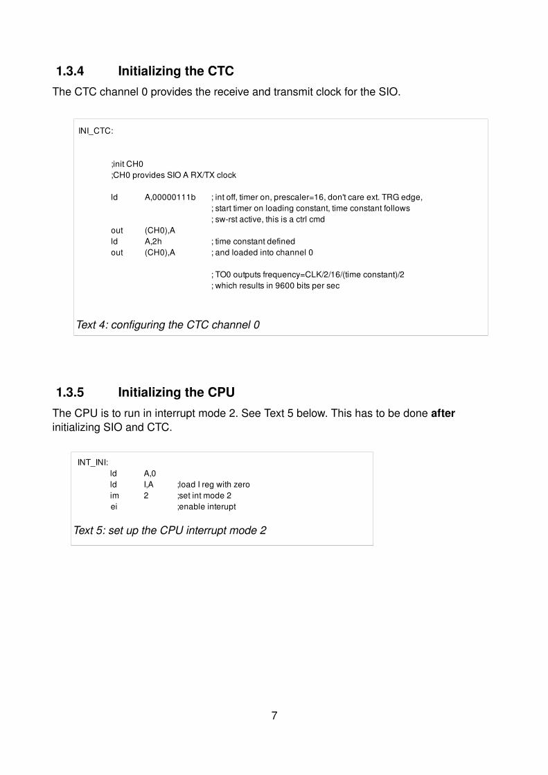
1.3.4 Initializing the CTCThe CTC channel 0 provides the receive and transmit clock for the SIO.
1.3.5 Initializing the CPUThe CPU is to run in interrupt mode 2. See Text 5 below. This has to be done after initializing SIO and CTC.
7
Text 5: set up the CPU interrupt mode 2
INT_INI:ld A,0ld I,A ;load I reg with zeroim 2 ;set int mode 2ei ;enable interupt
Text 4: configuring the CTC channel 0
INI_CTC:
;init CH0;CH0 provides SIO A RX/TX clock
ld A,00000111b ; int off, timer on, prescaler=16, don't care ext. TRG edge,; start timer on loading constant, time constant follows; swrst active, this is a ctrl cmd
out (CH0),Ald A,2h ; time constant definedout (CH0),A ; and loaded into channel 0
; TO0 outputs frequency=CLK/2/16/(time constant)/2; which results in 9600 bits per sec

1.3.6 Hardware Flow ControlIn order to signal the host whether the client is ready or not to receive a character the RTS line coming out of the client (and driving towards the host) needs to be switched. As earlier said I assume the host is much faster than the client, that why I do not implement a routine to check the CTSline coming from the host.
1.3.7 Disabling SIO RXchannelWhen certain conditions arise it might by important to disable the receive channel of the SIO (see routine in Text 7).
8
Text 6: signaling the host go or nogo for reception
A_RTS_OFF:ld a,005h ;write into WR0: select WR5out (SIO_A_C),Ald a,0E8h ;DTR active, TX 8bit, BREAK off, TX on, RTS inactiveout (SIO_A_C),Aret
A_RTS_ON:ld a,005h ;write into WR0: select WR5out (SIO_A_C),Ald a,0EAh ;DTR active, TX 8bit, BREAK off, TX on, RTS activeout (SIO_A_C),Aret
Text 7: Disabling the SIO
SIO_A_DI:;disable SIO channel A RXld a,003h ;write into WR0: select WR3out (SIO_A_C),Ald a,0C0h ;RX 8bit, auto enable off, RX offout (SIO_A_C),A;Channel A RX inactiveret

1.3.8 Interrupt Service RoutinesUpon reception of a character the routine RX_CHA_AVAILABLE shown in Text 8 is executed. Here you get the character set by the host. In the end of this routine, the character is sent back to the host by a simple single command
out (SIO_A_D),A
Note: In this example we backup only register AF. Depending on your application you might be required to backup more registers like HL, DE, CD, ...
Routine SPEC_RX_CONDITION is executed upon a special receive condition like buffer overrun. In my example the CPU is to jump at the warmstart location 0x0000.
Note: The code written in red might be required if you want the CPU to be ready for another interrupt (ei) and to give the host a go for another transmission (call A_RTS_ON).
I recommend to put these two lines not here but in your main program routine that processes the characters received by the SIO. This way you process one character after another and avoid overrunning your SIO RX buffer.
9
Text 8: character received routine
RX_CHA_AVAILABLE:
push AF ;backup AFcall A_RTS_OFFin A,(SIO_A_D) ;read RX character into A
; A holds received character
;do something with the received character
;echo character to hostout (SIO_A_D),Acall TX_EMPei ;see comments belowcall A_RTS_ON ;see comments belowpop AF ;restore AFReti
SPEC_RX_CONDITON:jp 0000h

1.3.9 Transmission of a character to the hostIn general transmitting of a character is done by the single command
out (SIO_A_D),A
as written in Text 8. To make sure the character has been sent completely the transmit buffer needs to be checked if it is empty. The general routine to achieve this is shown in Text 9.
10
Text 9: transmitting a character to host
TX_EMP:; check for TX buffer emptysub a ;clear a, write into WR0: select RR0inc a ;select RR1out (SIO_A_C),Ain A,(SIO_A_C) ;read RRxbit 0,Ajp z,TX_EMPret

2 File Transfer Mode
2.1 Desired Communication MechanismWe want to program the SIO for asynchronous RS232 XModem protocol with these parameters:
Baudrate: 9600 Baud/sec
Stopbits: 1
Startbits: 1
Character length: 8 bit
Parity: none
In difference to the character based mode described in part 1 (Terminal Mode) blocks of 128 byte size are to be transferred over the NullModemCable from the host PC to the client, the Z80machine. I choose the XModem protocol due to its robustness and easy feasibility. Typical terminal programs like HyperTerminal, Kermit or Minicom do support the XModem protocol.
Of course you can also transfer a file via character based mode but the transfer will take much more time.
Regarding the device structure, NullModemCable, wiring and flowcontrol please refer to section 1.1 on page 2 and 1.2 on page 3.
A web link to the description of the XModem protocol can be found in section 4 on page 19.
Note: For this mode the connection of the CPU pin /WAIT and the SIO pin /Wait/Ready is required. Please see section 1.2.1 on page 3.
11

2.2 ProgrammingFour problems have to be solved: initializing the SIO, implementing the interrupt mechanism, requesting the host to start the XModem transfer and load the file to a certain RAM location.
2.2.1 HeaderThe header show below defines the hardware addresses of the data and control port of your SIO and the address of your CTC channel 0. My hardware here uses the addresses 0x4, 0x6 and 0x0. Further on there is a RAM locations defined for counting bad blocks while the file is being transferred.
2.2.2 Interrupt Vector TableEvery time the SIO receives the first byte of a block it requests an interrupt causing the CPU to jump to the memory address specified by the term BYTE_AVAILABLE. This is the interrupt mode: interrupt on first character. Special receive conditions like receiver buffer overrun cause a jump to location SPEC_BYTE_COND. The latter case aborts the transfer.
2.2.3 Initializing the CTCPlease read section 1.3.4 on page 7.
12
Text 10: header
SIO_A_D equ 4hSIO_A_C equ 6hCH0 equ 0h
temp0 equ 1015h ;holds number of ;unsuccessful block transfers/block during download
Text 11: SIO interrupt vector table
INT_VEC:org 1ChDEFW BYTE_AVAILABLEorg 1EhDEFW SPEC_BYTE_COND

2.2.4 Initializing the CPUPlease read section 1.3.5 on page 7.
2.2.5 XModem File TransferThe assembly code of this module is described in the following sections. Due to its complexity I split it into parts shown in Text 12, 13 and 14 whose succession must not be mixed. For detailed information on the purpose of certain registers and control bits please read the SIO datasheet.
2.2.5.1 Host triggered transfer and setup
The host PC initiates the transfer. Using Minicom for example you press CTRLAS to get into a menu where you select the xmodem protocol and afterward into the file menu to select the file to be sent to the client. The procedure is similar with HyperTerminal.
After that the host waits for a NAK character sent by the client.
Now you should run the code shown below in Text 12 on your Z80machine. This code initializes the SIO for interrupt mode “interrupt on first received character”.
13
;set up TX and RX:
ld a,018h ;write into WR0: channel resetout (SIO_A_C),A
ld a,004h ;write into WR0: select WR4out (SIO_A_C),Ald a,44h ;44h write into WR4: clkx16,1 stop bit, no parityout (SIO_A_C),A
ld a,005h ;write into WR0: select WR5out (SIO_A_C),Ald a,0E8h ;DTR active, TX 8bit, BREAK off, TX on, RTS inactiveout (SIO_A_C),A
ld a,01h ;write into WR0: select WR1out (SIO_B_C),Ald a,00000100b ;no interrupt in CH B, special RX condition affects vectout (SIO_B_C),A
ld a,02h ;write into WR0: select WR2out (SIO_B_C),Ald a,10h ;write into WR2: cmd line int vect (see int vec table)out (SIO_B_C),A ;bits D3,D2,D1 are changed according to RX condition
Text 12: setup 1

Now we do some settings for bad block counting, the first block number to expect and the RAM destination address of the file to receive from the host. See Text 13. The destination address setting is red colored. From this RAM location onwards the file is to be stored. Im my example I use address 0x8000. Depending on your application you should change this value.
Text 14 shows the code section that prepares the CPU for the reception of the first byte of a data block. The line colored red makes the CPU waiting for an interrupt which is caused by the SIO. The belonging interrupt service routine is shown in Text 15.
Once a block has been received, the checksum is verified and possible bad blocks counted. The same data block is transferred maximal 10 times whereupon the transfer is aborted.
14
sub Ald (temp0),A ;reset bad blocks counterld C,1h ;C holds first block nr to expectld HL,8000h ;set lower destination address of file
call SIO_A_EIcall A_RTS_ON
call TX_NAK ;NAK indicates ready for transmission to host
Text 13: setup 2

15
REC_BLOCK:
;set block transfer modeld a,21h ;write into WR0 cmd4 and select WR1out (SIO_A_C),Ald a,10101000b ;wait active, interrupt on first RX characterout (SIO_A_C),A ;buffer overrun is a spec RX condition
eicall A_RTS_ONhalt ;await first rx charcall A_RTS_OFF
ld a,01h ;write into WR0: select WR1out (SIO_A_C),Ald a,00101000b ;wait function inactiveout (SIO_A_C),A
;check return code of block reception (e holds return code)ld a,ecp 0 ;block finished, no errorjp z,l_210cp 2 ;eot foundjp z,l_211cp 3 ;chk sum errorjp z,l_613ld a,10hjp l_612
l_210: call TX_ACK ;when no errorinc c ;prepare next block to receivesub Ald (temp0),A ;clear bad block counterjp REC_BLOCK
l_211: call TX_ACK ;on eotld A,01hjp l_612
l_613: call TX_NAK ;on chk sum errorscfccf ;clear carry flagld DE,0080h ;subtract 80hsbc HL,DE ;from HL, so HL is reset to block start address
ld A,(temp0) ;count bad blocks in temp0inc Ald (temp0),Acp 09hjp z,l_612 ;abort download after 9 attempts to transfer a blockjp REC_BLOCK ;repeat block reception
l_612:DLD_END:
ret
Text 14: Receive Data Block

16
BYTE_AVAILABLE:
EXP_SOH_EOT:in A,(SIO_A_D) ;read RX byte into A
l_205: cp 01h ;check for SOHjp z,EXP_BLK_NRcp 04h ;check for EOTjp nz,l_2020ld e,2hreti
;await block numberEXP_BLK_NR:
in A,(SIO_A_D) ;read RX byte into Acp C ;check for match of block nrjp nz,l_2020
;await complement of block numberld A,C ;copy block nr to expect into ACPL ;and cpl Ald E,A ;E holds cpl of block nr to expect
EXP_CPL_BLK_NR:in A,(SIO_A_D) ;read RX byte into Acp E ;check for cpl of block nrjp nz,l_2020
;await data blockld D,0h ;start value of checksumld B,80h ;defines block size 128byte
EXP_DATA:in A,(SIO_A_D) ;read RX byte into Ald (HL),Aadd A,D ;updateld D,A ;checksum in Dinc HL ;dest address +1djnz EXP_DATA ;loop until block finished
EXP_CHK_SUM:
in A,(SIO_A_D) ;read RX byte into A; ld a,045h ;for debug only
cp D ;check for checksum matchjp z,l_2021ld e,3hreti
l_2020: ld E,1hRETI
l_2021: ld E,0hRETI ;return when block received completely
;Int routine on RX overflow
SPEC_BYTE_COND: ;in case of RX overflow prepare abort of transfer ld HL,DLD_ENDpush HLreti
Text 15: Interrupt Service Routine

2.2.5.2 Subroutines
Important for the XModem protocol is the sending of the Acknowledge and the NotAcknowledge character to the host machine. For all other routines used in the code above please refer to sections 1.3.3 on page 6 and 1.3.6 on page 8.
17
TX_NAK:ld a,15h ;send NAK 15h to hostout (SIO_A_D),Acall TX_EMPRET
TX_ACK:ld a,6h ;send AK to hostout (SIO_A_D),Acall TX_EMPRET
Text 16: Acknowledge / NotAcknowledge

3 Z80 IC equivalents tableAn overview of ICs of the famous Z80 family gives Table 1.
device equivalent typeZ80CPU BU18400APS (ROHM)
D780C1(NEC)KP1858BM1/2/3 / KR1858BM1/2/3 (USSR)LH0080 (Sharp)MK3880x (Mostek) T34VM1 / T34BM1 (USSR)TMPZ84C00AP8 (Toshiba)UA880 / UB880 / VB880D (MME) Z0840004 (ZiLOG)Z0840006 (ZiLOG)Z80ACPUD1 (SGSAtes)Z84C00AB6 (SGSThomson)Z84C00 (ZiLOG)Z8400A (Goldstar)U84C00 (MME)
Z80SIO UA8560 , UB8560 (MME) Z0844004 (ZiLOG)Z8440AB1 (ST)Z0844006 (ZiLOG)Z84C40 (ZiLOG)U84C40 (MME)
Z80PIO Z0842004/6 (ZiLOG)UA855 / UB855 (MME) Z84C20 (ZiLOG)U84C20 (MME)
Z80CTC Z84C30 (ZiLOG)U84C30 (MME) UA857 / UB857 (MME)
Table 1: Z80 equivalents
18

4 Useful Links
A complete embedded Z80 system can be found at
http://www.trainz.de/trainz
The Free and Open Productivity Suite OpenOffice at http://www.openoffice.org
Z80 assembler for Linux and UNIX at http://www.unix4fun.org/z80pack/
The powerful communication tool Kermit at http://www.columbia.edu/kermit/
The Z80 history at http://en.wikipedia.org/wiki/Zilog_Z80
The XModem Protocol Reference
at http://www.trainz. de/trainz/pdf/xymodem.pdf
EAGLE an affordable and very efficient schematics and layout tool at http://www.cadsoftusa.com/
5 Further ReadingI recommend to read these books:
“Using CKermit” / Frank da Cruz, Christine M. Gianone / ISBN 1555581080 (english)
“CKermit : Einführung und Referenz” / Frank da Cruz, Christine M. Gianone / ISBN 3882290234 (german)
6 DisclaimerThis tutorial is believed to be accurate and reliable. I do not assume responsibility for any errors which may appear in this document. I reserve the right to change it at any time without notice, and do not make any commitment to update the information contained herein.
My Boss is a Jewish Carpenter
19