hp 3600 v2 switch series - apache welcome pageh20628. · hp 3600 v2 switch series layer 3 ......
TRANSCRIPT

HP 3600 v2 Switch Series Layer 3 - IP Routing Configuration Guide
Part number: 5998-2352
Software version: Release 2101
Document version: 6W101-20130930

Legal and notice information
© Copyright 2013 Hewlett-Packard Development Company, L.P.
No part of this documentation may be reproduced or transmitted in any form or by any means without prior written consent of Hewlett-Packard Development Company, L.P.
The information contained herein is subject to change without notice.
HEWLETT-PACKARD COMPANY MAKES NO WARRANTY OF ANY KIND WITH REGARD TO THIS MATERIAL, INCLUDING, BUT NOT LIMITED TO, THE IMPLIED WARRANTIES OF MERCHANTABILITY AND FITNESS FOR A PARTICULAR PURPOSE. Hewlett-Packard shall not be liable for errors contained herein or for incidental or consequential damages in connection with the furnishing, performance, or use of this material.
The only warranties for HP products and services are set forth in the express warranty statements accompanying such products and services. Nothing herein should be construed as constituting an additional warranty. HP shall not be liable for technical or editorial errors or omissions contained herein.

i
Contents
IP routing basics ··························································································································································· 1 IP routing overview ··························································································································································· 1
Routing table ····························································································································································· 1 Dynamic routing protocols ······································································································································ 2 Routing preference ··················································································································································· 3 Load sharing ····························································································································································· 3 Route backup ···························································································································································· 4 Route recursion ························································································································································· 4 Route redistribution ··················································································································································· 4
Displaying and maintaining a routing table ·················································································································· 4
Static routing configuration ········································································································································· 6 Introduction ········································································································································································ 6
Static route ································································································································································ 6 Default route ······························································································································································ 6 Static route configuration items ······························································································································· 6
Configuring a static route ················································································································································· 7 Configuration prerequisites ····································································································································· 7 Configuration procedure ········································································································································· 7
Configuring BFD for static routes ····································································································································· 8 BFD control packet mode ········································································································································ 8 BFD echo packet mode ············································································································································ 9
Configuring static route FRR ············································································································································· 9 Displaying and maintaining static routes ···················································································································· 10 Static route configuration examples ····························································································································· 11
Basic static route configuration example ············································································································ 11 Static route FRR configuration example ·············································································································· 13 BFD for static routes configuration example (direct session) ············································································ 15 BFD for static routes configuration example (indirect session) ········································································· 17
RIP configuration ························································································································································ 20 RIP overview ··································································································································································· 20
RIP working mechanism ········································································································································ 20 Operation of RIP ···················································································································································· 21 RIP version ······························································································································································ 21 RIP message format ··············································································································································· 22 Supported RIP features ·········································································································································· 23 Protocols and standards ······································································································································· 24
RIP configuration task list ··············································································································································· 24 Configuring RIP basic functions ···································································································································· 25
Configuration prerequisites ·································································································································· 25 Configuration procedure ······································································································································ 25
Configuring RIP route control ········································································································································ 27 Configuring an additional routing metric ··········································································································· 27 Configuring RIPv2 route summarization·············································································································· 27 Disabling host route reception ····························································································································· 28 Advertising a default route ··································································································································· 29 Configuring inbound or outbound route filtering ······························································································· 29 Configuring a priority for RIP ······························································································································· 30 Configuring RIP route redistribution ····················································································································· 30

ii
Tuning and optimizing RIP networks ···························································································································· 31 Configuring RIP timers ··········································································································································· 31 Configuring split horizon and poison reverse ···································································································· 31 Configuring the maximum number of load balanced routes ············································································ 32 Enabling zero field check on incoming RIPv1 messages ·················································································· 32 Enabling source IP address check on incoming RIP updates ············································································ 33 Configuring RIPv2 message authentication ········································································································ 33 Specifying a RIP neighbor ···································································································································· 34 Configuring RIP-to-MIB binding ···························································································································· 34 Configuring the RIP packet sending rate ············································································································ 34
Configuring RIP FRR ······················································································································································· 35 Configuring BFD for RIP ················································································································································· 36
Single-hop detection in BFD echo packet mode ································································································ 36 Bidirectional detection in BFD control packet mode ·························································································· 36
Displaying and maintaining RIP ··································································································································· 37 RIP configuration examples ··········································································································································· 37
Configuring RIP version ········································································································································ 37 Configuring RIP route redistribution ····················································································································· 39 Configuring an additional metric for a RIP interface ························································································· 41 Configuring RIP to advertise a summary route ··································································································· 43 RIP FRR configuration example ···························································································································· 45 Configuring BFD for RIP (single-hop detection in BFD echo packet mode) ····················································· 47 Configuring BFD for RIP (bidirectional detection in BFD control packet mode) ·············································· 50
Troubleshooting RIP ························································································································································ 53 No RIP updates received ······································································································································ 53 Route oscillation occurred ···································································································································· 53
OSPF configuration ···················································································································································· 55 Introduction to OSPF ······················································································································································ 55
Basic concepts ······················································································································································· 55 Area based OSPF network partition ··················································································································· 57 Router types ···························································································································································· 60 Classification of OSPF networks ·························································································································· 61 DR and BDR ··························································································································································· 62 OSPF packet formats ············································································································································· 63 Supported features ················································································································································ 71 Protocols and standards ······································································································································· 72
OSPF configuration task list ·········································································································································· 72 Enabling OSPF ······························································································································································· 73
Configuration prerequisites ·································································································································· 73 Configuration procedure ······································································································································ 74
Configuring OSPF areas ··············································································································································· 75 Configuration prerequisites ·································································································································· 75 Configuring a stub area ······································································································································· 75 Configuring an NSSA area ·································································································································· 76 Configuring a virtual link ······································································································································ 76
Configuring OSPF network types ································································································································· 77 Configuration prerequisites ·································································································································· 77 Configuring the OSPF network type for an interface as broadcast ································································· 78 Configuring the OSPF network type for an interface as NBMA ······································································ 78 Configuring the OSPF network type for an interface as P2MP ········································································ 79 Configuring the OSPF network type for an interface as P2P ············································································ 79
Configuring OSPF route control ··································································································································· 80 Configuration prerequisites ·································································································································· 80 Configuring OSPF route summarization ············································································································· 80

iii
Configuring OSPF inbound route filtering ·········································································································· 81 Configuring ABR Type-3 LSA filtering ················································································································· 82 Configuring an OSPF cost for an interface ········································································································ 82 Configuring the maximum number of OSPF routes ··························································································· 83 Configuring the maximum number of load-balanced routes ············································································ 83 Configuring OSPF preference ······························································································································ 83 Configuring OSPF route redistribution ················································································································ 84 Advertising a host route ········································································································································ 85
Tuning and optimizing OSPF networks ························································································································ 85 Configuration prerequisites ·································································································································· 86 Configuring OSPF packet timers ·························································································································· 86 Specifying LSA transmission delay ······················································································································ 87 Specifying SPF calculation interval ······················································································································ 87 Specifying the LSA arrival interval ······················································································································· 87 Specifying the LSA generation interval ··············································································································· 88 Disabling interfaces from receiving and sending OSPF packets ······································································ 88 Configuring stub routers ······································································································································· 89 Configuring OSPF authentication ························································································································ 89 Adding the interface MTU into DD packets ········································································································ 90 Configuring the maximum number of external LSAs in LSDB ··········································································· 90 Enabling compatibility with RFC 1583 ··············································································································· 90 Logging neighbor state changes ·························································································································· 91 Configuring OSPF network management ··········································································································· 91 Enabling message logging ··································································································································· 92 Enabling the advertisement and reception of opaque LSAs ············································································· 92 Configuring OSPF to give priority to receiving and processing hello packets ··············································· 92 Configuring the LSU transmit rate ························································································································ 93 Enabling OSPF ISPF ·············································································································································· 93
Configuring OSPF FRR ··················································································································································· 93 Configuring OSPF Graceful Restart ······························································································································ 95
Configuring the OSPF GR Restarter ····················································································································· 95 Configuring the OSPF GR Helper ························································································································ 96 Triggering OSPF Graceful Restart ························································································································ 97
Configuring BFD for OSPF ············································································································································ 97 Configuring control packet bidirectional detection ··························································································· 97 Configuring echo packet single-hop detection ··································································································· 97
Displaying and maintaining OSPF ······························································································································· 98 OSPF configuration examples ······································································································································ 99
Configuring OSPF basic functions ······················································································································· 99 Configuring OSPF route redistribution ·············································································································· 103 Configuring OSPF to advertise a summary route ····························································································· 104 Configuring an OSPF stub area························································································································· 107 Configuring an OSPF NSSA area ····················································································································· 109 Configuring OSPF DR election ··························································································································· 111 Configuring OSPF virtual links ··························································································································· 115 Configuring OSPF Graceful Restart ··················································································································· 117 Configuring route filtering ·································································································································· 120 Configuring OSPF FRR ········································································································································ 122 Configuring BFD for OSPF ································································································································· 124
Troubleshooting OSPF configuration ························································································································· 128 No OSPF neighbor relationship established ···································································································· 128 Incorrect routing information ······························································································································ 129
IS-IS configuration ··················································································································································· 130 IS-IS overview ······························································································································································· 130

iv
Basic concepts ····················································································································································· 130 IS-IS area ······························································································································································ 132 IS-IS network type ················································································································································ 134 IS-IS PDU format ··················································································································································· 135 Supported IS-IS features ······································································································································ 141 Protocols and standards ····································································································································· 143
IS-IS configuration task list ··········································································································································· 143 Configuring IS-IS basic functions ································································································································ 144
Configuration prerequisites ································································································································ 144 Enabling IS-IS ······················································································································································· 145 Configuring the IS level and circuit level ·········································································································· 145 Configuring the network type of an interface as P2P ······················································································ 146
Configuring IS-IS routing information control ············································································································ 146 Configuration prerequisites ································································································································ 146 Configuring IS-IS link cost ··································································································································· 146 Specifying a priority for IS-IS ····························································································································· 148 Configuring the maximum number of equal cost routes·················································································· 148 Configuring IS-IS route summarization ·············································································································· 148 Advertising a default route ································································································································· 149 Configuring IS-IS route redistribution ················································································································ 149 Configuring IS-IS route filtering ·························································································································· 150 Configuring IS-IS route leaking ·························································································································· 151
Tuning and optimizing IS-IS networks ························································································································ 151 Configuration prerequisites ································································································································ 151 Specifying intervals for sending IS-IS hello and CSNP packets ····································································· 151 Specifying the IS-IS hello multiplier ···················································································································· 152 Configuring a DIS priority for an interface ······································································································· 152 Disabling an interface from sending or receiving IS-IS packets ····································································· 153 Enabling an interface to send small hello packets ··························································································· 153 Configuring LSP parameters ······························································································································· 153 Configuring SPF parameters ······························································································································ 156 Assigning a high priority to IS-IS routes ············································································································ 156 Setting the LSDB overload bit ····························································································································· 156 Configuring system ID to host name mappings ································································································ 157 Enabling the logging of neighbor state changes ····························································································· 158
Enhancing IS-IS network security ································································································································ 158 Configuration prerequisites ································································································································ 158 Configuring neighbor relationship authentication ··························································································· 158 Configuring area authentication ························································································································ 159 Configuring routing domain authentication ······································································································ 159
Configuring IS-IS GR ···················································································································································· 160 Configuring IS-IS NSR ·················································································································································· 160 Configuring IS-IS FRR ··················································································································································· 161 Enabling IS-IS SNMP trap ··········································································································································· 162 Binding an IS-IS process with MIBs ···························································································································· 162 Configuring BFD for IS-IS ············································································································································· 163 Displaying and maintaining IS-IS ······························································································································· 163 IS-IS configuration examples ······································································································································· 164
IS-IS basic configuration ····································································································································· 164 DIS election configuration ·································································································································· 169 Configuring IS-IS route redistribution ················································································································ 173 IS-IS Graceful Restart configuration example ··································································································· 176 IS-IS NSR configuration example ······················································································································· 178 IS-IS FRR configuration example ························································································································ 180

v
IS-IS authentication configuration example······································································································· 183 Configuring BFD for IS-IS ···································································································································· 185
BGP configuration ··················································································································································· 189 BGP overview ······························································································································································· 189
Formats of BGP messages ·································································································································· 189 BGP path attributes ············································································································································· 192 BGP route selection ············································································································································· 196 iBGP and IGP synchronization ·························································································································· 198 Settlements for problems in large scale BGP networks ··················································································· 198 BGP GR ································································································································································ 201 MP-BGP ································································································································································· 202 Protocols and standards ····································································································································· 202
BGP configuration task list ·········································································································································· 203 Configuring BGP basic functions ································································································································ 204
Configuration prerequisites ································································································································ 204 Creating a BGP connection ································································································································ 204 Specifying the source interface for TCP connections ······················································································· 205 Allowing establishment of eBGP connection to an indirectly connected peer or peer group ····················· 206
Controlling route generation ······································································································································· 206 Configuration prerequisites ································································································································ 206 Injecting a local network ···································································································································· 207 Configuring BGP route redistribution ················································································································ 207 Enabling default route redistribution into BGP ································································································· 207
Controlling route distribution and reception ············································································································· 208 Configuration prerequisites ································································································································ 208 Configuring BGP route summarization ············································································································· 208 Advertising a default route to a peer or peer group ······················································································· 209 Configuring BGP route distribution/reception filtering policies ····································································· 209 Enabling BGP and IGP route synchronization ································································································· 210 Limiting prefixes received from a peer or peer group ····················································································· 211 Configuring BGP route dampening ··················································································································· 211 Configuring a shortcut route······························································································································· 212
Configuring BGP route attributes ································································································································ 212 Configuration prerequisites ································································································································ 212 Specifying a preferred value for routes received ····························································································· 212 Configuring preferences for BGP routes ··········································································································· 213 Configure the default local preference ············································································································· 213 Configuring the MED attribute ··························································································································· 213 Configuring the next hop attribute ····················································································································· 215 Configuring the AS-PATH attribute ···················································································································· 216
Tuning and optimizing BGP networks ························································································································ 219 Configuration prerequisites ································································································································ 219 Configuring the BGP keepalive interval and holdtime ···················································································· 219 Configuring the interval for sending the same update ···················································································· 220 Configuring BGP soft-reset ·································································································································· 220 Enabling the BGP ORF capability······················································································································ 221 Enabling 4-byte AS number suppression ·········································································································· 222 Enabling quick eBGP session reestablishment ································································································· 223 Enabling MD5 authentication for TCP connections ························································································· 223 Configuring BGP load balancing ······················································································································ 223 Forbiding session establishment with a peer or peer group ··········································································· 224
Configuring a large scale BGP network ···················································································································· 224 Configuration prerequisites ································································································································ 224 Configuring BGP peer groups ··························································································································· 224

vi
Configuring BGP community ······························································································································ 226 Configuring a BGP route reflector ····················································································································· 227 Configuring a BGP confederation ····················································································································· 227
Configuring BGP GR ··················································································································································· 228 Enabling trap ································································································································································ 229 Enabling logging of peer state changes ···················································································································· 229 Configuring BFD for BGP ············································································································································ 230 Displaying and maintaining BGP ······························································································································· 230
Displaying BGP ···················································································································································· 230 Resetting BGP connections ································································································································· 231 Clearing BGP information ·································································································································· 232
BGP configuration examples······································································································································· 232 BGP basic configuration ····································································································································· 232 BGP and IGP synchronization configuration ···································································································· 236 BGP load balancing configuration ···················································································································· 239 BGP community configuration ···························································································································· 241 BGP route reflector configuration ······················································································································ 243 BGP confederation configuration ······················································································································ 245 BGP path selection configuration ······················································································································ 249 BGP GR configuration ········································································································································· 252 Configuring BFD for BGP ··································································································································· 253
Troubleshooting BGP ··················································································································································· 258 BGP peer relationship not established ·············································································································· 258
IPv6 static routing configuration ····························································································································· 259 Introduction to IPv6 static routing ······························································································································· 259
Features of IPv6 static routes ······························································································································ 259 Default IPv6 route ················································································································································ 259
Configuring an IPv6 static route ································································································································· 259 Configuration prerequisites ································································································································ 259 Configuration procedure ···································································································································· 259
Displaying and maintaining IPv6 static routes ·········································································································· 260 IPv6 static routing configuration example ················································································································· 260
RIPng configuration ················································································································································· 263 Introduction to RIPng ···················································································································································· 263
RIPng working mechanism ·································································································································· 263 RIPng packet format ············································································································································ 264 RIPng packet processing procedure ·················································································································· 265 Protocols and standards ····································································································································· 265
RIPng configuration task list ········································································································································ 265 Configuring RIPng basic functions ······························································································································ 266
Configuration prerequisites ································································································································ 266 Configuration procedure ···································································································································· 266
Configuring RIPng route control ································································································································· 266 Configuring an additional routing metric ········································································································· 267 Configuring RIPng route summarization ··········································································································· 267 Advertising a default route ································································································································· 267 Configuring a RIPng route filtering policy ········································································································· 268 Configuring a priority for RIPng ························································································································· 268 Configuring RIPng route redistribution ·············································································································· 268
Tuning and optimizing the RIPng network ················································································································· 269 Configuring RIPng timers ···································································································································· 269 Configuring split horizon and poison reverse ·································································································· 269 Configuring zero field check on RIPng packets ······························································································· 270

vii
Configuring the maximum number of equal cost routes for load balancing ················································ 270 Applying IPsec policies for RIPng ······························································································································· 271 Displaying and maintaining RIPng ····························································································································· 272 RIPng configuration examples····································································································································· 272
Configuring RIPng basic functions ····················································································································· 272 Configuring RIPng route redistribution ·············································································································· 275 Configuring RIPng IPsec policies ······················································································································· 277
OSPFv3 configuration ············································································································································· 280 Introduction to OSPFv3 ················································································································································ 280
OSPFv3 overview ················································································································································ 280 OSPFv3 packets··················································································································································· 280 OSPFv3 LSA types ··············································································································································· 281 Timers of OSPFv3 ················································································································································ 281 OSPFv3 features supported ································································································································ 282 Protocols and standards ····································································································································· 282
OSPFv3 configuration task list ···································································································································· 282 Enabling OSPFv3 ························································································································································· 283
Configuration prerequisites ································································································································ 283 Enabling OSPFv3 ················································································································································ 283
Configuring OSPFv3 area parameters ······················································································································ 284 Configuration prerequisites ································································································································ 284 Configuring an OSPFv3 stub area ···················································································································· 284 Configuring an OSPFv3 virtual link ··················································································································· 285
Configuring OSPFv3 network types ··························································································································· 285 Configuration prerequisites ································································································································ 286 Configuring the OSPFv3 network type for an interface ·················································································· 286 Configuring an NBMA or P2MP neighbor ······································································································· 286
Configuring OSPFv3 routing information control ····································································································· 286 Configuration prerequisites ································································································································ 286 Configuring OSPFv3 route summarization ······································································································· 287 Configuring OSPFv3 inbound route filtering ···································································································· 287 Configuring an OSPFv3 cost for an interface ·································································································· 287 Configuring the maximum number of OSPFv3 load-balanced routes ··························································· 288 Configuring a priority for OSPFv3 ···················································································································· 288 Configuring OSPFv3 route redistribution ·········································································································· 289
Tuning and optimizing OSPFv3 networks ················································································································· 289 Configuration prerequisites ································································································································ 290 Configuring OSPFv3 timers ································································································································ 290 Configuring a DR priority for an interface ········································································································ 291 Ignoring MTU check for DD packets ················································································································· 291 Disable interfaces from receiving and sending OSPFv3 packets ··································································· 291 Enable the logging of neighbor state changes ································································································ 292
Configuring OSPFv3 GR ············································································································································· 292 Configuring GR Restarter ···································································································································· 292 Configuring GR Helper ······································································································································· 293
Configuring BFD for OSPFv3 ······································································································································ 293 Applying IPsec policies for OSPFv3 ··························································································································· 294 Displaying and maintaining OSPFv3 ························································································································· 295 OSPFv3 configuration examples ································································································································ 296
Configuring OSPFv3 areas ································································································································ 296 Configuring OSPFv3 DR election ······················································································································· 300 Configuring OSPFv3 route redistribution ·········································································································· 302 Configuring OSPFv3 GR ···································································································································· 305 Configuring BFD for OSPFv3 ····························································································································· 307

viii
Configuring OSPFv3 IPsec policies ··················································································································· 310 Troubleshooting OSPFv3 configuration ····················································································································· 313
No OSPFv3 neighbor relationship established ································································································ 313 Incorrect routing information ······························································································································ 314
IPv6 IS-IS configuration ··········································································································································· 315 Introduction to IPv6 IS-IS ·············································································································································· 315 Configuring IPv6 IS-IS basic functions ························································································································ 315
Configuration prerequisites ································································································································ 315 Configuration procedure ···································································································································· 315
Configuring IPv6 IS-IS routing information control ··································································································· 316 Configuration prerequisites ································································································································ 316 Configuration procedure ···································································································································· 316
Configuring BFD for IPv6 IS-IS ···································································································································· 317 Displaying and maintaining IPv6 IS-IS ······················································································································· 318 IPv6 IS-IS configuration examples ······························································································································ 319
IPv6 IS-IS basic configuration example ············································································································· 319 Configuring BFD for IPv6 IS-IS ··························································································································· 323
IPv6 BGP configuration ··········································································································································· 327 IPv6 BGP overview ······················································································································································· 327 IPv6 BGP configuration task list ·································································································································· 328 Configuring IPv6 BGP basic functions ······················································································································· 329
Configuration prerequisites ································································································································ 329 Specifying an IPv6 BGP peer ····························································································································· 329 Injecting a local IPv6 route ································································································································· 329 Configuring a preferred value for routes from a peer or peer group ···························································· 330 Specifying the source interface for establishing TCP connections ································································· 330 Allowing the establishment of an indirect eBGP connection ·········································································· 331 Configuring a description for an IPv6 peer or peer group ············································································· 331 Disabling session establishment to an IPv6 peer or peer group ···································································· 331 Logging IPv6 peer or peer group state changes ······························································································ 332
Controlling route distribution and reception ············································································································· 332 Configuration prerequisites ································································································································ 332 Configuring IPv6 BGP route redistribution ········································································································ 332 Configuring IPv6 BGP route summarization ····································································································· 333 Advertising a default route to an IPv6 peer or peer group ············································································· 333 Configuring outbound route filtering ················································································································· 333 Configuring inbound route filtering ··················································································································· 334 Configuring IPv6 BGP and IGP route synchronization ···················································································· 335 Configuring route dampening ···························································································································· 335
Configuring IPv6 BGP route attributes ······················································································································· 335 Configuration prerequisites ································································································································ 336 Configuring IPv6 BGP preference and default LOCAL_PREF and NEXT_HOP attributes ···························· 336 Configuring the MED attribute ··························································································································· 336 Configuring the AS_PATH attribute ··················································································································· 337
Tuning and optimizing IPv6 BGP networks ··············································································································· 337 Configuration prerequisites ································································································································ 338 Configuring IPv6 BGP timers ······························································································································ 338 Configuring IPv6 BGP soft reset ························································································································· 339 Enabling the IPv6 BGP ORF capability ············································································································· 339 Enabling 4-byte AS number suppression ·········································································································· 340 Configuring the maximum number of load-balanced routes ·········································································· 341 Enabling MD5 authentication for TCP connections ························································································· 341 Applying an IPsec policy to an IPv6 BGP peer or peer group ······································································· 342

ix
Configuring a large-scale IPv6 BGP network ············································································································ 342 Configuration prerequisites ································································································································ 343 Configuring IPv6 BGP peer group ····················································································································· 343 Configuring IPv6 BGP community ····················································································································· 344 Configuring an IPv6 BGP route reflector··········································································································· 345
Configuring BFD for IPv6 BGP ···································································································································· 345 Displaying and maintaining IPv6 BGP ······················································································································· 346
Displaying BGP ···················································································································································· 346 Resetting IPv6 BGP connections ························································································································· 347 Clearing IPv6 BGP information ·························································································································· 347
IPv6 BGP configuration examples ······························································································································ 347 IPv6 BGP basic configuration example ············································································································· 347 IPv6 BGP route reflector configuration example ······························································································ 349 IPv6 BGP IPsec policy configuration example ·································································································· 351 Configuring BFD for IPv6 BGP ··························································································································· 355
Troubleshooting IPv6 BGP configuration ··················································································································· 360 IPv6 BGP peer relationship not established ······································································································ 360
Routing policy configuration ·································································································································· 361 Introduction to routing policy ······································································································································ 361
Routing policy application ·································································································································· 361 Routing policy implementation ··························································································································· 361 Filters ····································································································································································· 361
Routing policy configuration task list·························································································································· 363 Defining filters ······························································································································································· 363
Prerequisites ························································································································································· 363 Defining an IP-prefix list ······································································································································ 363 Defining an AS path list ······································································································································ 364 Defining a community list ··································································································································· 364 Defining an extended community list ················································································································ 365
Configuring a routing policy ······································································································································· 365 Prerequisites ························································································································································· 365 Creating a routing policy ··································································································································· 365 Defining if-match clauses ···································································································································· 366 Defining apply clauses ········································································································································ 367 Defining a continue clause ································································································································· 369
Displaying and maintaining the routing policy ········································································································· 369 Routing policy configuration examples ······················································································································ 370
Applying a routing policy to IPv4 route redistribution ····················································································· 370 Applying a routing policy to IPv6 route redistribution ····················································································· 373 Applying a routing policy to filter received BGP routes ·················································································· 374
Troubleshooting routing policy configuration············································································································ 377 IPv4 routing information filtering failure············································································································ 377 IPv6 routing information filtering failure············································································································ 377
Policy-based routing configuration ························································································································ 378 Introduction to PBR ······················································································································································· 378
PBR modes ···························································································································································· 378 Concepts······························································································································································· 379 QoS mode ···························································································································································· 379
Configuring PBR (using a PBR policy) ························································································································ 380 Defining a policy ················································································································································· 380 Configuring local PBR ········································································································································· 381 Configuring interface PBR ·································································································································· 381 PBR and track ······················································································································································· 382

x
Configuring PBR (using a QoS policy) ······················································································································· 382 Configuring a QoS policy ·································································································································· 382 Applying the QoS policy ···································································································································· 382
Displaying and maintaining PBR configuration ········································································································ 383 PBR configuration (using a PBR policy) ············································································································· 383 PBR configuration (using a QoS policy) ············································································································ 384
PBR configuration examples ········································································································································ 385 Configuring local PBR based on packet type ··································································································· 385 Configuring interface PBR based on packet type ···························································································· 386 IPv4 PBR configuration example (using a QoS policy) ··················································································· 388 IPv6 PBR configuration example (using a QoS policy) ··················································································· 389
MCE configuration ·················································································································································· 391 MCE overview ······························································································································································ 391
MPLS L3VPN overview ········································································································································ 391 MPLS L3VPN concepts ········································································································································ 392 Multi-VPN-instance CE ········································································································································ 394 How MCE works ················································································································································· 395 Using MCE in tunneling applications ················································································································ 395
Configuring routing on an MCE ································································································································· 396 Route exchange between an MCE and a VPN site ························································································· 396 Route exchange between an MCE and a PE ··································································································· 398
Configuring an MCE ··················································································································································· 398 Configuring VPN instances ································································································································ 398
Configuring routing on an MCE ································································································································· 400 Configuration prerequisites ································································································································ 400 Configuring routing between MCE and VPN site ···························································································· 401 Configuring routing between MCE and PE ······································································································ 405
Displaying and maintaining MCE ······························································································································ 408 Resetting BGP connections ································································································································· 408 Displaying and maintaining MCE ····················································································································· 409
MCE configuration examples ····································································································································· 410 Using OSPF to advertise VPN routes to the PE ································································································· 410 Using BGP to advertise VPN routes to the PE ··································································································· 415 Using tunnels to advertise VPN routes ·············································································································· 418
Support and other resources ·································································································································· 425 Contacting HP ······························································································································································ 425
Subscription service ············································································································································ 425 Related information ······················································································································································ 425
Documents ···························································································································································· 425 Websites ······························································································································································· 425
Conventions ·································································································································································· 426
Index ········································································································································································ 428

1
IP routing basics
NOTE:
• The term router in this document refers to both routers and Layer 3 switches.
• The types of interfaces that appear in any figures other than the network diagrams for configuration examples are for illustration only. Some of them might be unavailable on your switch.
• The term interface in the routing features refers to Layer 3 interfaces, including VLAN interfaces and route-mode (or Layer 3) Ethernet ports. You can set an Ethernet port to operate in route mode by usingthe port link-mode route command (see Layer 2—LAN Switching Configuration Guide).
• The 3600 v2 SI Switch Series does not support OSPF, BGP, IS-IS, OSPFv3, IPv6 BGP, or IPv6 IS-IS.
IP routing overview Upon receiving a packet, a router determines the optimal route based on the destination address and forwards the packet to the next router in the path. When the packet reaches the last router, it then forwards the packet to the destination host.
Routing provides the path information that guides the forwarding of packets.
Routes can be divided into the following categories by destination:
• Network route—The destination is a network. The subnet mask is less than 32 bits.
• Host route—The destination is a host. The subnet mask is 32 bits.
Routes can be divided into the following types based on whether the destination is directly connected to the router:
• Direct routes—The destination is directly connected to the router.
• Indirect routes—The destination is not directly connected to the router.
Routing table Introduction to routing table
A router selects optimal routes from the routing table, and sends them to the forwarding information base (FIB) table to guide packet forwarding. Each router maintains a routing table and a FIB table.
Routes in a routing table can be divided into the following categories by origin:
• Direct routes—Routes discovered by data link protocols, also known as “interface routes”
• Static routes—Routes manually configured. Static routes are easy to configure and require less system resources. They work well in small and stable networks. Static routes cannot adjust to network changes. You must manually configure the routes again whenever the network topology changes.
• Dynamic routes—Routes discovered dynamically by routing protocols
Each entry in the FIB table specifies a physical interface that packets destined for a certain address should go out to reach the next hop—the next router—or the directly connected destination.

2
NOTE:
For more information about the FIB table, see Layer 3—IP Services Configuration Guide.
Routing table information
Display the brief information of a routing table by using the display ip routing-table command.
For example: <Sysname> display ip routing-table
Routing Tables: Public
Destinations : 7 Routes : 7
Destination/Mask Proto Pre Cost NextHop Interface
1.1.1.0/24 Direct 0 0 1.1.1.1 Vlan11
2.2.2.0/24 Static 60 0 12.2.2.2 Vlan12
80.1.1.0/24 OSPF 10 2 80.1.1.1 Vlan13
…(Part of the output information is omitted)
A route entry includes the following key items:
• Destination—Destination IP address or destination network
• Mask—The network mask specifies, in company with the destination address, the address of the destination network. A logical AND operation between the destination address and the network mask yields the address of the destination network. For example, if the destination address is 129.102.8.10 and the mask 255.255.0.0, the address of the destination network is 129.102.0.0. A network mask is made up of a certain number of consecutive 1s. It can be expressed in dotted decimal format or by the number of the 1s.
• Pre—Preference of the route. Among routes to the same destination, the one with the highest preference is optimal.
• Cost—When multiple routes to a destination have the same preference, the one with the smallest cost becomes the optimal route.
• NextHop—Specifies the IP address of the next hop
• Interface—Specifies the interface through which a matching IP packet is to be forwarded
Dynamic routing protocols Based on dynamic routing protocols, dynamic routing can detect network topology changes and recalculate the routes, so it is suitable for large networks. However, dynamic routing is difficult to configure, imposes higher requirements on the system, and consumes a certain amount of network resources.
Dynamic routing protocols can be classified based on different criteria, as shown in Table 1:
Table 1 Dynamic routing protocols
Criterion Categories
Optional scope
• Interior gateway protocols (IGPs)—Work within an autonomous system (AS). Examples include RIP, OSPF, and IS-IS.
• Exterior gateway protocols (EGPs)—Work between ASs. The most popular one is BGP.

3
Criterion Categories
Routing algorithm • Distance-vector protocols—RIP and BGP. BGP is also considered a path-vector
protocol. • Link-state protocols—OSPF and IS-IS
Destination address type
• Unicast routing protocols—RIP, OSPF, BGP, and IS-IS • Multicast routing protocols—PIM-SM and PIM-DM
IP version • IPv4 routing protocols—RIP, OSPF, BGP, and IS-IS • IPv6 routing protocols—RIPng, OSPFv3, IPv6 BGP, and IPv6 IS-IS
NOTE:
• An AS refers to a group of routers sharing the same routing policy and working under the same administration.
• This chapter focuses on unicast routing protocols. For more information about multicast routing protocols, see IP Multicast Configuration Guide.
Routing preference Different routing protocols can find different routes to the same destination. However, not all of those routes are optimal. For route selection, routing protocols, direct routes, and static routes are assigned different preferences. The route with the highest preference is preferred.
The preference of a direct route is always 0 and cannot be changed. You can manually configure preferences for any other route type. Each static route can be configured with a different preference. The following table lists the types of routes and the default preferences. The smaller the preference value, the higher the preference.
Routing approach Preference
Direct route 0
OSPF 10
IS-IS 15
Static route 60
RIP 100
OSPF ASE 150
OSPF NSSA 150
iBGP 255
eBGP 255
Unknown (route from an untrusted source) 256
Load sharing A routing protocol can be configured with multiple equal-cost routes to the same destination. These routes have the same preference and will all be used to accomplish load sharing if there is no route with a higher preference available.

4
NOTE:
At present, routing protocols supporting load sharing include static routing/IPv6 static routing, RIP/RIPng,OSPF/OSPFv3, BGP/IPv6 BGP, and IS-IS/IPv6 IS-IS.
Route backup Route backup can help improve network reliability. With route backup, you can configure multiple routes to the same destination, expecting the one with the highest preference to be the main route and all the rest backup routes.
Under normal circumstances, packets are forwarded through the main route. When the link fails, the route with the highest preference among the backup routes is selected to forward packets. When the link recovers, the route selection process is performed again and the main route is selected again to forward packets.
Route recursion The next hops of some BGP routes (except eBGP routes) and static routes may not be directly connected. The outgoing interface to reach the next hop must be available. Route recursion is used to find the outgoing interface based on the next hop information of the route. Link-state routing protocols, such as OSPF and IS-IS, do not need route recursion because they obtain next hop information through route calculation.
Route redistribution Different routing protocols running on a network learn route information from each other through route redistribution. Each routing protocol can redistribute routes from other protocols, direct routes, and static routes. For more information, see relevant protocols in this configuration guide.
Displaying and maintaining a routing table To do… Use the command… Remarks
Display information about the routing table
display ip routing-table [ vpn-instance vpn-instance-name ] [ verbose ] [ | { begin | exclude | include } regular-expression ]
Available in any view
Display information about routes permitted by an IPv4 basic ACL
display ip routing-table [ vpn-instance vpn-instance-name ] acl acl-number [ verbose ] [ | { begin | exclude | include } regular-expression ]
Available in any view
Display information about routes to the specified destination
display ip routing-table [ vpn-instance vpn-instance-name ] ip-address [ mask | mask-length ] [ longer-match ] [ verbose ] [ | { begin | exclude | include } regular-expression ]
Available in any view
Display information about routes with destination addresses in the specified range
display ip routing-table [ vpn-instance vpn-instance-name ] ip-address1 { mask | mask-length } ip-address2 { mask | mask-length } [ verbose ] [ | { begin | exclude | include } regular-expression ]
Available in any view

5
To do… Use the command… Remarks
Display routing information permitted by an IPv4 prefix list
display ip routing-table [ vpn-instance vpn-instance-name ] ip-prefix ip-prefix-name [ verbose ] [ | { begin | exclude | include } regular-expression ]
Available in any view
Display routes of a routing protocol
display ip routing-table [ vpn-instance vpn-instance-name ] protocol protocol [ inactive | verbose ] [ | { begin | exclude | include } regular-expression ] [ | { begin | exclude | include } regular-expression ] [ | { begin | exclude | include } regular-expression ]
Available in any view
Display statistics about the routing table
display ip routing-table [ vpn-instance vpn-instance-name ] statistics [ | { begin | exclude | include } regular-expression ]
Available in any view
Clear statistics for the routing table reset ip routing-table statistics protocol [ vpn-instance vpn-instance-name ] { protocol | all }
Available in user view
Display IPv6 routing table information
display ipv6 routing-table [ verbose ] [ | { begin | exclude | include } regular-expression ]
Available in any view
Display routing information permitted by an IPv6 ACL
display ipv6 routing-table acl acl6-number [ verbose ] [ | { begin | exclude | include } regular-expression ]
Available in any view
Display routing information for a specified destination IPv6 address
display ipv6 routing-table ipv6-address prefix-length [ longer-match ] [ verbose ] [ | { begin | exclude | include } regular-expression ]
Available in any view
Display IPv6 routing information for an IPv6 address range
display ipv6 routing-table ipv6-address1 prefix-length1 ipv6-address2 prefix-length2 [ verbose ] [ | { begin | exclude | include } regular-expression ]
Available in any view
Display routing information permitted by an IPv6 prefix list
display ipv6 routing-table ipv6-prefix ipv6-prefix-name [ verbose ] [ | { begin | exclude | include } regular-expression ]
Available in any view
Display IPv6 routing information of a routing protocol
display ipv6 routing-table protocol protocol [ inactive | verbose ] [ | { begin | exclude | include } regular-expression ]
Available in any view
Display IPv6 routing statistics display ipv6 routing-table statistics [ | { begin | exclude | include } regular-expression ]
Available in any view
Clear specified IPv6 routing statistics
reset ipv6 routing-table statistics protocol { protocol | all } Available in user view

6
Static routing configuration
NOTE:
The term router in this document refers to both routers and Layer 3 switches.
Introduction
Static route Static routes are manually configured. If a network’s topology is simple, you only need to configure static routes for the network to work properly. The proper configuration and usage of static routes can improve network performance and ensure bandwidth for important network applications.
The disadvantage of using static routes is that they cannot adapt to network topology changes. If a fault or a topological change occurs in the network, the relevant routes will be unreachable and the network breaks. When this happens, the network administrator must modify the static routes manually.
Default route Without a default route, a packet that does not match any routing entries is discarded.
A default route is used to forward packets that do not match any routing entry. It can be configured in either of the following ways:
• The network administrator can configure a default route with both the destination and mask being 0.0.0.0. The router forwards any packet whose destination address fails to match any entry in the routing table to the next hop of the default static route.
• Some dynamic routing protocols, such as OSPF, RIP, and IS-IS, can also generate a default route. For example, an upstream router running OSPF can generate a default route and advertise it to other routers, which install the default route with the next hop being the upstream router.
Static route configuration items Before configuring a static route, you must know the following concepts:
1. Destination address and mask
In the ip route-static command, an IPv4 address is in dotted decimal format. A mask can be either in dotted decimal format or in the form of mask length—the number of consecutive 1s in the mask.
2. Output interface and next hop address
When you configure a static route, specify either the output interface, next hop address, or both depending on the specific occasion. The next hop address cannot be a local interface IP address; otherwise, the route configuration will not take effect.
Each route lookup operation has to find the next hop to resolve the destination link layer address.
When specifying the output interface, observe the following rules:
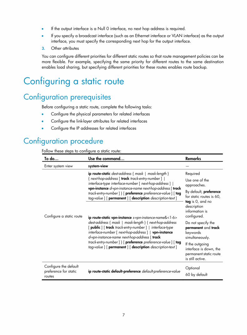
7
• If the output interface is a Null 0 interface, no next hop address is required.
• If you specify a broadcast interface (such as an Ethernet interface or VLAN interface) as the output interface, you must specify the corresponding next hop for the output interface.
3. Other attributes
You can configure different priorities for different static routes so that route management policies can be more flexible. For example, specifying the same priority for different routes to the same destination enables load sharing, but specifying different priorities for these routes enables route backup.
Configuring a static route
Configuration prerequisites Before configuring a static route, complete the following tasks:
• Configure the physical parameters for related interfaces
• Configure the link-layer attributes for related interfaces
• Configure the IP addresses for related interfaces
Configuration procedure Follow these steps to configure a static route:
To do… Use the command… Remarks
Enter system view system-view —
Configure a static route
ip route-static dest-address { mask | mask-length } { next-hop-address [ track track-entry-number ] | interface-type interface-number [ next-hop-address ] | vpn-instance d-vpn-instance-name next-hop-address [ track track-entry-number ] } [ preference preference-value ] [ tag tag-value ] [ permanent ] [ description description-text ]
Required
Use one of the approaches.
By default, preference for static routes is 60, tag is 0, and no description information is configured.
Do not specify the permanent and track keywords simultaneously.
If the outgoing interface is down, the permanent static route is still active.
ip route-static vpn-instance s-vpn-instance-name&<1-6> dest-address { mask | mask-length } { next-hop-address [ public ] [ track track-entry-number ] | interface-type interface-number [ next-hop-address ] | vpn-instance d-vpn-instance-name next-hop-address [ track track-entry-number ] } [ preference preference-value ] [ tag tag-value ] [ permanent ] [ description description-text ]
Configure the default preference for static routes
ip route-static default-preference default-preference-value Optional
60 by default

8
NOTE:
• When you configure a static route, the static route does not take effect if you specify the next hop addressfirst and then configure it as the IP address of a local interface, such as Ethernet interface and VLAN interface.
• If you do not specify the preference when you configure a static route, the default preference will be used. Reconfiguring the default preference applies only to newly created static routes.
• You can flexibly control static routes by configuring tag values and using the tag values in the routing policy.
• If the destination IP address and mask are both configured as 0.0.0.0 with the ip route-static command,then the route is the default route.
• For detailed information about track, see High Availability Configuration Guide.
Configuring BFD for static routes Bidirectional forwarding detection (BFD) provides a general-purpose, standard, medium-, and protocol-independent fast failure detection mechanism. It can uniformly and quickly detect the failures of the bidirectional forwarding paths between two routers for protocols, such as routing protocols. For more information about BFD, see High Availability Configuration Guide.
A dynamic routing protocol notifies BFD of its neighbor information. BFD uses such information to establish sessions with neighbors by sending BFD control packets. Static routing has no neighbor discovery mechanism. This section describes how static routing implements BFD.
BFD control packet mode To use BFD control packets for bidirectional detection between two devices, you must enable BFD control packet mode for each device’s static route destined to the peer.
To configure a static route and enable BFD control packet mode for it, specify an outbound interface and a direct next hop—BFD establishes a direct session, or specify an indirect next hop and a specific BFD packet source address—BFD establishes an indirect session—for the static route.
Follow these steps to configure a static route with BFD control packet mode enabled (direct session):
To do… Use the command… Remarks
Enter system view system-view —
Configure a static route and enable BFD control packet mode for it
ip route-static dest-address { mask | mask-length } interface-type interface-number next-hop-address bfd control-packet [ preference preference-value ] [ tag tag-value ] [ description description-text ] Required
Use either command
ip route-static vpn-instance s-vpn-instance-name&<1-6> dest-address { mask | mask-length } interface-type interface-number next-hop-address bfd control-packet [ preference preference-value ] [ tag tag-value ] [ description description-text ]
Follow these steps to configure a static route with BFD control packet mode enabled (indirect session):
To do… Use the command… Remarks
Enter system view system-view —

9
To do… Use the command… Remarks
Configure a static route and enable BFD control packet mode for it
ip route-static dest-address { mask | mask-length } next-hop-address bfd control-packet bfd-source ip-address [ preference preference-value ] [ tag tag-value ] [ description description-text ] Required
Use either command ip route-static vpn-instance s-vpn-instance-name&<1-6>
dest-address { mask | mask-length } next-hop-address bfd control-packet bfd-source ip-address [ preference preference-value ] [ tag tag-value ] [ description description-text ]
BFD echo packet mode With BFD echo packet mode enabled for a static route, the local device sends BFD echo packets to the peer, which loops it back to test the link.
Follow these steps to configure BFD echo packet mode for static routes:
To do… Use the command… Remarks
Enter system view system-view —
Configure the source address of echo packets bfd echo-source-ip ip-address
Required
Not configured by default
Enable BFD echo packet mode for static routes
ip route-static dest-address { mask | mask-length } interface-type interface-number next-hop-address bfd echo-packet [ preference preference-value ] [ tag tag-value ] [ description description-text ]
Use either command ip route-static vpn-instance s-vpn-instance-name&<1-6>
dest-address { mask | mask-length } interface-type interface-number next-hop-address bfd echo-packet [ preference preference-value ] [ tag tag-value ] [ description description-text ]
NOTE:
• If route flaps occur, enabling BFD could worsen them.
• For the echo mode, only one end needs to establish the BFD session, and the source address of echo packets must be configured.
• BFD cannot be used for a static route with the outbound interface having the spoofing attribute.
Configuring static route FRR When a link or a router fails, the packets on the path may be discarded, or a routing loop occurs. To avoid such problems, you can enable static route fast reroute (FRR).

10
Figure 1 Network diagram
As shown in Figure 1, upon a link failure, FRR designates a backup next hop by using a routing policy for routes matching the specified criteria. Packets are directed to the backup next hop to avoid traffic interruption.
Configuration prerequisites
Configuring static route FRR needs to reference a routing policy. You can specify a backup next hop in a routing policy by using the apply fast-reroute backup-interface command. For more information about the command and routing policy configurations, see the chapter “Routing policy configuration.”
Configuration procedure
Follow these steps to configure static route FRR:
To do… Use the command… Remarks
Enter system view system-view —
Configure the source address of echo packets
bfd echo-source-ip ip-address Required
Not configured by default.
Configure static route FRR ip route-static [ vpn-instance vpn-instance-name ] fast-reroute route-policy route-policy-name
Required
Not configured by default.
NOTE:
• Static route FRR takes effect only for static routes that have both the outbound interface and next hop specified.
• Do not use FRR and BFD at the same time.
Displaying and maintaining static routes To do… Use the command… Remarks
Display information of static routes display ip routing-table protocol static [ inactive | verbose ] [ | { begin | exclude | include } regular-expression ]
Available in any view
Delete all the static routes delete [ vpn-instance vpn-instance-name ] static-routes all
Available in system view
NOTE:
For more information about the display ip routing-table protocol static [ inactive | verbose ] [ | { begin| exclude | include } regular-expression ] command, see Layer 3—IP Routing Command Reference.

11
Static route configuration examples
Basic static route configuration example Network requirements
The IP addresses and masks of the switches and hosts are shown in Figure 2. Static routes are required for interconnection between any two hosts.
Figure 2 Network diagram
Configuration procedure
1. Configure IP addresses for interfaces. (Details not shown)
2. Configure static routes.
# Configure a default route on Switch A. <SwitchA> system-view
[SwitchA] ip route-static 0.0.0.0 0.0.0.0 1.1.4.2
# Configure two static routes on Switch B. <SwitchB> system-view
[SwitchB] ip route-static 1.1.2.0 255.255.255.0 1.1.4.1
[SwitchB] ip route-static 1.1.3.0 255.255.255.0 1.1.5.6
# Configure a default route on Switch C <SwitchC> system-view
[SwitchC] ip route-static 0.0.0.0 0.0.0.0 1.1.5.5
3. Configure the hosts.
The default gateways for hosts A, B, and C are 1.1.2.3, 1.1.6.1 and 1.1.3.1, respectively. The configuration procedure is not shown.
4. Display the configuration.
# Display the IP routing table of Switch A. [SwitchA] display ip routing-table
Routing Tables: Public
Destinations : 7 Routes : 7

12
Destination/Mask Proto Pre Cost NextHop Interface
0.0.0.0/0 Static 60 0 1.1.4.2 Vlan500
1.1.2.0/24 Direct 0 0 1.1.2.3 Vlan300
1.1.2.3/32 Direct 0 0 127.0.0.1 InLoop0
1.1.4.0/30 Direct 0 0 1.1.4.1 Vlan500
1.1.4.1/32 Direct 0 0 127.0.0.1 InLoop0
127.0.0.0/8 Direct 0 0 127.0.0.1 InLoop0
127.0.0.1/32 Direct 0 0 127.0.0.1 InLoop0
# Display the IP routing table of Switch B. [SwitchB] display ip routing-table
Routing Tables: Public
Destinations : 10 Routes : 10
Destination/Mask Proto Pre Cost NextHop Interface
1.1.2.0/24 Static 60 0 1.1.4.1 Vlan500
1.1.3.0/24 Static 60 0 1.1.5.6 Vlan600
1.1.4.0/30 Direct 0 0 1.1.4.2 Vlan500
1.1.4.2/32 Direct 0 0 127.0.0.1 InLoop0
1.1.5.4/30 Direct 0 0 1.1.5.5 Vlan600
1.1.5.5/32 Direct 0 0 127.0.0.1 InLoop0
127.0.0.0/8 Direct 0 0 127.0.0.1 InLoop0
127.0.0.1/32 Direct 0 0 127.0.0.1 InLoop0
1.1.6.0/24 Direct 0 0 1.1.6.1 Vlan100
1.1.6.1/32 Direct 0 0 127.0.0.1 InLoop0
# Use the ping command on Host B to check the reachability of Host A, assuming Windows XP runs on the two hosts. C:\Documents and Settings\Administrator>ping 1.1.2.2
Pinging 1.1.2.2 with 32 bytes of data:
Reply from 1.1.2.2: bytes=32 time=1ms TTL=255
Reply from 1.1.2.2: bytes=32 time=1ms TTL=255
Reply from 1.1.2.2: bytes=32 time=1ms TTL=255
Reply from 1.1.2.2: bytes=32 time=1ms TTL=255
Ping statistics for 1.1.2.2:
Packets: Sent = 4, Received = 4, Lost = 0 (0% loss),
Approximate round trip times in milli-seconds:
Minimum = 1ms, Maximum = 1ms, Average = 1ms
# Use the tracert command on Host B to check the reachability of Host A. C:\Documents and Settings\Administrator>tracert 1.1.2.2
Tracing route to 1.1.2.2 over a maximum of 30 hops
1 <1 ms <1 ms <1 ms 1.1.6.1

13
2 <1 ms <1 ms <1 ms 1.1.4.1
3 1 ms <1 ms <1 ms 1.1.2.2
Trace complete.
Static route FRR configuration example Network requirements
Switch S, Switch A, and Switch D are interconnected through static routes, as illustrated in Figure 3. Configure static route FRR so that when the link between Switch S and Switch D fails, traffic can be switched to Link B immediately.
Figure 3 Network diagram
Switch S Switch D
Switch A
Loop 01.1.1.1/32
Vlan-int100
12.12.12.1/24
Vlan-int20013.13.13.1/24
Vlan-int20013.13.13.2/24
Vlan-int100
12.12.12.2/24Vlan-int101
24.24.24.2/24 Vlan-int101
24.24.24.4/24Loop 0
4.4.4.4/32
Link A
Link B
Configuration procedure
1. Configure IP addresses for the interfaces on each switch and configure static routes.
Follow Figure 3 to configure the IP address and subnet mask of each interface on the switches. (Details not shown)
Configure static routes on Switch S, Switch A, and Switch D so that Switch S can reach Loopback 0 on Switch D and Switch D can reach Loopback 0 on Switch S.
# Configure a static route on Switch S. <SwitchS> system-view
[SwitchS] ip route-static 4.4.4.4 32 vlan-interface 200 13.13.13.2
[SwitchS] ip route-static 4.4.4.4 32 vlan-interface 100 12.12.12.2 preference 65
# Configure a static route on Switch D. <SwitchD> system-view
[SwitchD] ip route-static 1.1.1.1 32 vlan-interface 200 13.13.13.1
[SwitchD] ip route-static 1.1.1.1 32 vlan-interface 101 24.24.24.2 preference 65
# Configure a static route on Switch A. <SwitchA> system-view
[SwitchA] ip route-static 4.4.4.4 32 vlan-interface 101 24.24.24.4
[SwitchA] ip route-static 1.1.1.1 32 vlan-interface 100 12.12.12.1
2. Configure static route FRR.
# Configure Switch S. [SwitchS] bfd echo-source-ip 1.1.1.1
[SwitchS] ip ip-prefix abc index 10 permit 4.4.4.4 32
[SwitchS] route-policy frr permit node 10
[SwitchS-route-policy] if-match ip-prefix abc

14
[SwitchS-route-policy] apply fast-reroute backup-interface vlan-interface 100 backup-nexthop 12.12.12.2
[SwitchS-route-policy] quit
[SwitchS] ip route-static fast-reroute route-policy frr
# Configure Switch D. [SwitchD] bfd echo-source-ip 4.4.4.4
[SwitchD] ip ip-prefix abc index 10 permit 1.1.1.1 32
[SwitchD] route-policy frr permit node 10
[SwitchD-route-policy] if-match ip-prefix abc
[SwitchD-route-policy] apply fast-reroute backup-interface vlan-interface 101 backup-nexthop 24.24.24.2
[SwitchD-route-policy] quit
[SwitchD] ip route-static fast-reroute route-policy frr
3. Verify the configuration.
# Display route 4.4.4.4/32 on Switch S to view the backup next hop information. [SwitchS] display ip routing-table 4.4.4.4 verbose
Routing Table : Public
Summary Count : 1
Destination: 4.4.4.4/32
Protocol: Static Process ID: 0
Preference: 60 Cost: 0
IpPrecedence: QosLcId:
NextHop: 13.13.13.2 Interface: vlan 200
BkNextHop: 12.12.12.2 BkInterface: vlan 100
RelyNextHop: 0.0.0.0 Neighbor : 0.0.0.0
Tunnel ID: 0x0 Label: NULL
BKTunnel ID: 0x0 BKLabel: NULL
State: Active Adv Age: 00h01m27s
Tag: 0
# Display route 1.1.1.1/32 on Switch D to view the backup next hop information. [SwitchD] display ip routing-table 1.1.1.1 verbose
Routing Table : Public
Summary Count : 1
Destination: 1.1.1.1/32
Protocol: Static Process ID: 0
Preference: 60 Cost: 0
IpPrecedence: QosLcId:
NextHop: 13.13.13.1 Interface: vlan 200
BkNextHop: 24.24.24.2 BkInterface: vlan 101
RelyNextHop: 0.0.0.0 Neighbor : 0.0.0.0
Tunnel ID: 0x0 Label: NULL
BKTunnel ID: 0x0 BKLabel: NULL
State: Active Adv Age: 00h01m27s
Tag: 0

15
BFD for static routes configuration example (direct session) Network requirements
As shown in Figure 4, configure static routes to subnet 120.1.1.0/24 on Switch A, static routes to subnet 121.1.1.0/24 on Switch B, and static routes to subnets 120.1.1.0/24 and 121.1.1.0/24 on Switch C.
Enable BFD so that when the link between Switch A and Switch B through the Layer 2 switch fails, BFD can detect the failure immediately and Switch A and Switch B can communicate through Switch C.
Figure 4 Network diagram
Device Interface IP address Device Interface IP address Switch A Vlan-int10 12.1.1.1/24 Switch B Vlan-int10 12.1.1.2/24 Vlan-int11 10.1.1.102/24 Vlan-int13 13.1.1.1/24 Switch C Vlan-int11 10.1.1.100/24 Vlan-int13 13.1.1.2/24
Configuration procedure
1. Configure IP addresses for the interfaces. (Details not shown)
2. Configure BFD.
# Configure static routes on Switch A and enable BFD control packet mode for the static route through the Layer 2 switch. <SwitchA> system-view
[SwitchA] interface vlan-interface10
[SwitchA-vlan-interface10] bfd min-transmit-interval 500
[SwitchA-vlan-interface10] bfd min-receive-interval 500
[SwitchA-vlan-interface10] bfd detect-multiplier 9
[SwitchA-vlan-interface10] quit
[SwitchA] ip route-static 120.1.1.0 24 vlan-interface 10 12.1.1.2 bfd control-packet
[SwitchA] ip route-static 120.1.1.0 24 vlan-interface 11 10.1.1.100 preference 65
[SwitchA] quit
# Configure static routes on Switch B and enable BFD control packet mode for the static route through the Layer 2 switch. <SwitchB> system-view
[SwitchB] interface vlan-interface10
[SwitchB-vlan-interface10] bfd min-transmit-interval 500
[SwitchB-vlan-interface10] bfd min-receive-interval 500
[SwitchB-vlan-interface10] bfd detect-multiplier 9
[SwitchB-vlan-interface10]] quit

16
[SwitchB] ip route-static 121.1.1.0 24 vlan-interface 10 12.1.1.1 bfd control-packet
[SwitchB] ip route-static 121.1.1.0 24 vlan-interface 13 13.1.1.2 preference 65
[SwitchB] quit
# Configure static routes on Switch C. <SwitchC> system-view
[SwitchC] ip route-static 120.1.1.0 24 vlan-interface 13 13.1.1.1
[SwitchC] ip route-static 121.1.1.0 24 vlan-interface 11 10.1.1.102
3. Verify the configuration.
The following operations are performed on Switch A. The operations on Switch B are similar. <SwitchA> display bfd session
Total Session Num: 1 Init Mode: Active
Session Working Under Ctrl Mode:
LD/RD SourceAddr DestAddr State Holdtime Interface
4/7 12.1.1.1 12.1.1.2 Up 2000ms Vlan10
# Display the static route information of Switch A. <SwitchA> display ip routing-table protocol static
Public Routing Table : Static
Summary Count : 2
Static Routing table Status : < Active>
Summary Count : 1
Destination/Mask Proto Pre Cost NextHop Interface
120.1.1.0/24 Static 60 0 12.1.1.2 Vlan10
Direct Routing table Status : <Inactive>
Summary Count : 1
Destination/Mask Proto Pre Cost NextHop Interface
120.1.1.0/24 Static 65 0 10.1.1.100 Vlan11
# Enable BFD debugging on Switch A. When the link between Switch A and Layer 2 switch fails, Switch A can detect the failure. <SwitchA> debugging bfd event
<SwitchA> debugging bfd scm
<SwitchA> terminal debugging
%Jul 27 10:18:18:672 2007 SwitchA BFD/4/LOG:Sess[12.1.1.1/12.1.1.2, Vlan10,Ctrl], Sta: UP->DOWN, Diag: 1
*Jul 27 10:18:18:672 2007 SwitchA BFD/7/EVENT:Send sess-down Msg, [Src:12.1.1.1,Dst:12.1.1.2, Vlan10,Ctrl], instance:0, protocol:STATIC
*Jul 27 10:18:19:172 2007 SwitchA BFD/7/EVENT:Receive Delete-sess, [Src:12.1.1.1,Dst:12.1.1.2, Vlan10,Ctrl], Direct, Instance:0x0, Proto:STATIC
*Jul 27 10:18:19:172 2007 SwitchA BFD/7/EVENT:Notify driver to stop receiving bfd control packet
# Display the static route information on Switch A again. Switch A communicates with Switch B over the static route passing Switch C now. <SwitchA> display ip routing-table protocol static

17
Public Routing Table : Static
Summary Count : 2
Static Routing table Status : < Active>
Summary Count : 1
Destination/Mask Proto Pre Cost NextHop Interface
120.1.1.0/24 Static 65 0 10.1.1.100 Vlan11
Static Routing table Status : < Inactive>
Summary Count : 1
Destination/Mask Proto Pre Cost NextHop Interface
120.1.1.0/24 Static 60 0 12.1.1.2 Vlan10
BFD for static routes configuration example (indirect session) Network requirements
As shown in Figure 5, Switch A has a route to interface Loopback1 (2.2.2.9/32) on Switch B, with outbound interface VLAN-interface 10. Switch B has a route to interface Loopback1 (1.1.1.9/32) on Switch A, with outbound interface VLAN-interface 12. Switch D has a route to 1.1.1.9/32, with outbound interface VLAN-interface 10, and a route to 2.2.2.9/32, with outbound interface VLAN-interface 12.
Configure static routes to subnet 120.1.1.0/24 on Switch A, static routes to subnet 121.1.1.0/24 on Switch B, and static routes to subnets 120.1.1.0/24 and 121.1.1.0/24 on both Switch C and Switch D. Enable BFD so that when the link between Switch A and Switch B through Switch D fails, BFD can detect the failure immediately and Switch A and Switch B can communicate through Switch C.
Figure 5 Network diagram
Switch A Switch B
Switch C
BFD
Vlan-int10
Vlan-int11
Vlan-int11 Vlan-int13
Vlan-in
t13Vlan-int10
121.1.1.0/24 120.1.1.0/24
Switch DVlan-int12
Vlan-int12
Loop11.1.1.9/32
Loop12.2.2.9/32
Device Interface IP address Device Interface IP address Switch A Vlan-int10 12.1.1.1/24 Switch B Vlan-int12 11.1.1.1/24 Vlan-int11 10.1.1.102/24 Vlan-int13 13.1.1.1/24 Loop1 1.1.1.9/32 Loop1 2.2.2.9/32 Switch C Vlan-int11 10.1.1.100/24 Switch D Vlan-int10 12.1.1.2/24 Vlan-int13 13.1.1.2/24 Vlan-int12 11.1.1.2/24
Configuration procedure
1. Configure IP addresses for the interfaces. (Details not shown)
2. Configure BFD.
# Configure static routes on Switch A and enable BFD control packet mode for the static route through Switch D. <SwitchA> system-view

18
[SwitchA] interface loopback 1
[SwitchA-LoopBack1] bfd min-transmit-interval 500
[SwitchA-LoopBack1] bfd min-receive-interval 500
[SwitchA-LoopBack1] bfd detect-multiplier 9
[SwitchA-LoopBack1] quit
[SwitchA] ip route-static 120.1.1.0 24 2.2.2.9 bfd control-packet bfd-source 1.1.1.9
[SwitchA] ip route-static 120.1.1.0 24 vlan-interface 11 10.1.1.100 preference 65
[SwitchA] quit
# Configure static routes on Switch B and enable BFD control packet mode for the static route through Switch D. <SwitchB> system-view
[SwitchB] interface loopback 1
[SwitchB-LoopBack1] bfd min-transmit-interval 500
[SwitchB-LoopBack1] bfd min-receive-interval 500
[SwitchB-LoopBack1] bfd detect-multiplier 9
[SwitchB-LoopBack1] quit
[SwitchB] ip route-static 121.1.1.0 24 1.1.1.9 bfd control-packet bfd-source 2.2.2.9
[SwitchB] ip route-static 121.1.1.0 24 vlan-interface 13 13.1.1.2 preference 65
[SwitchB] quit
# Configure static routes on Switch C. <SwitchC> system-view
[SwitchC] ip route-static 120.1.1.0 24 vlan-interface 13 13.1.1.1
[SwitchC] ip route-static 121.1.1.0 24 vlan-interface 11 10.1.1.102
# Configure static routes on Switch D. <SwitchD> system-view
[SwitchD] ip route-static 120.1.1.0 24 vlan-interface 12 11.1.1.1
[SwitchD] ip route-static 121.1.1.0 24 vlan-interface 10 12.1.1.1
3. Verify the configuration.
The following operations are performed on Switch A. The operations on Switch B are similar and not shown.
# Display the BFD session information of Switch A. <SwitchA> display bfd session
Total Session Num: 1 Init Mode: Active
Session Working Under Ctrl Mode:
LD/RD SourceAddr DestAddr State Holdtime Interface
4/7 1.1.1.9 2.2.2.9 Up 2000ms Loop1
# Display the static route information of Switch A. <SwitchA> display ip routing-table protocol static
Public Routing Table : Static
Summary Count : 2
Static Routing table Status : < Active>
Summary Count : 1

19
Destination/Mask Proto Pre Cost NextHop Interface
120.1.1.0/24 Static 60 0 2.2.2.9 Vlan10
Static Routing table Status : <Inactive>
Summary Count : 1
Destination/Mask Proto Pre Cost NextHop Interface
120.1.1.0/24 Static 65 0 10.1.1.100 Vlan11
# Enable BFD debugging on Switch A. When the link between Switch A and Switch D fails, Switch A can detect the failure. <SwitchA> debugging bfd event
<SwitchA> debugging bfd scm
<SwitchA> terminal debugging
%Oct 10 10:18:18:672 2010 SwitchA BFD/4/LOG:Sess[1.1.1.9/2.2.2.9, Loop1,Ctrl], Sta: UP->DOWN, Diag: 1
* Oct 10 10:18:18:672 2010 SwitchA BFD/7/EVENT:Send sess-down Msg, [Src:1.1.1.9,Dst:2.2.2.9, Loop1,Ctrl], instance:0, protocol:STATIC
# Display the static route information on Switch A again. Switch A communicates with Switch B over the static route passing Switch C now. <SwitchA> display ip routing-table protocol static
Public Routing Table : Static
Summary Count : 2
Static Routing table Status : < Active>
Summary Count : 1
Destination/Mask Proto Pre Cost NextHop Interface
120.1.1.0/24 Static 65 0 10.1.1.100 Vlan11
Static Routing table Status : < Inactive>
Summary Count : 1
Destination/Mask Proto Pre Cost NextHop Interface
120.1.1.0/24 Static 60 0 2.2.2.9

20
RIP configuration
NOTE:
The term router in this document refers to both routers and Layer 3 switches.
RIP overview RIP is a simple Interior Gateway Protocol (IGP), mainly used in small-sized networks, such as academic networks and simple LANs. It is not applicable to complex networks.
RIP is widely used in practical networking because it is easy to implement, configure, and maintain.
RIP working mechanism Introduction
RIP is a distance vector routing protocol, using UDP packets for exchanging information through port 520.
RIP uses a hop count to measure the distance to a destination. The hop count from a router to a directly connected network is 0. The hop count from a router to a directly connected router is 1. To limit convergence time, the RIP metric value is in the range of 0 to 15. A metric value of 16 (or greater) is considered infinite, which means the destination network is unreachable. Because of this, RIP is not suitable for large-sized networks.
RIP prevents routing loops by implementing the split horizon and poison reverse functions.
RIP routing table
A RIP router has a routing table containing routing entries of all reachable destinations, and each routing entry contains the following elements:
• Destination address—IP address of a host or a network
• Next hop—IP address of the adjacent router’s interface to reach the destination
• Egress interface—Packet outgoing interface
• Metric—Cost from the local router to the destination
• Route time—Time elapsed since the routing entry was last updated. The time is reset to 0 every time the routing entry is updated.
• Route tag—Identifies a route, used in a routing policy to flexibly control routes. For more information about routing policy, see the chapter “Routing policy configuration.”
RIP timers
RIP employs the following timers—update, timeout, suppress, and garbage-collect.
• Update timer—Defines the interval between routing updates
• Timeout timer—Defines the route aging time. If no update for a route is received within the aging time, the metric of the route is set to 16 in the routing table.

21
• Suppress timer—Defines how long a RIP route stays in suppressed state. When the metric of a route is 16, the route enters the suppressed state. In suppressed state, only routes coming from the same neighbor and whose metric is less than 16 will be received by the router to replace unreachable routes.
• Garbage-collect timer—Defines the interval from when the metric of a route becomes 16 to when it is deleted from the routing table. During the garbage-collect timer length, RIP advertises the route with the routing metric set to 16. If no update is announced for that route after the garbage-collect timer expires, then the route is deleted from the routing table.
Routing loops prevention
RIP is a distance vector (D-V) routing protocol. Because a RIP router advertises its own routing table to neighbors, routing loops may occur.
RIP uses the following mechanisms to prevent routing loops:
• Counting to infinity—The metric value of 16 is defined as unreachable. When a routing loop occurs, the metric value of the route will increment to 16.
• Split horizon—A router does not send routing information back to the neighboring router the information came from, preventing routing loops and saving bandwidth.
• Poison reverse—A router sets the metric of routes received from a neighbor to 16 and sends back these routes to the neighbor to help delete such information from the neighbor’s routing table.
• Triggered updates—A router advertises updates once the metric of a route is changed instead of after the update period expires to speed up network convergence.
Operation of RIP The following procedure describes how RIP works:
1. After RIP is enabled, the router sends request messages to neighboring routers. Neighboring routers return response messages, including information about their routing tables.
2. After receiving this information, the router updates its local routing table, and sends triggered update messages to its neighbors. All routers on the network do this to keep the latest routing information.
3. By default, a RIP router sends its routing table to neighbors every 30 seconds.
4. RIP ages out routes by adopting an aging mechanism to keep only valid routes.
RIP version RIP has the following versions: RIPv1 and RIPv2.
RIPv1, a classful routing protocol, supports message advertisement through broadcast only. RIPv1 protocol messages do not carry mask information, so it can only recognize routing information of natural networks such as Class A, B, and C. For this reason, RIPv1 does not support discontiguous subnets.
RIPv2 is a classless routing protocol and has the following advantages over RIPv1.
• Supports route tags, which are used in routing policies to flexibly control routes.
• Supports masks, route summarization, and Classless Inter-Domain Routing (CIDR).
• Supports designated next hops to select the best ones on broadcast networks.
• Supports multicasting routing updates to reduce resource consumption. Only RIPv2 routers can receive these update messages.

22
• Supports plain text authentication and MD5 authentication to enhance security.
NOTE:
RIPv2 has two types of message transmission: broadcast and multicast. Multicast is the default type using224.0.0.9 as the multicast address. The interface working in the RIPv2 broadcast mode can also receiveRIPv1 messages.
RIP message format A RIP message consists of a header and up to 25 route entries. (A RIPv2 authentication message uses the first route entry as the authentication entry, leaving 24 available.)
RIPv1 message format
Figure 6 RIPv1 message format
• Command—Type of message. 1 indicates request, which is used to request all or part of the routing information from the neighbor; 2 indicates response, which contains all or part of the routing information. A response message consists of up to 25 route entries.
• Version—Version of RIP, 0x01 for RIPv1.
• Must be zero—This field must be zero
• AFI—Address Family Identifier, 2 for IP.
• IP address—Destination IP address of the route that can be a natural network, subnet, or a host address.
• Metric—Cost of the route
RIPv2 message format
The format of RIPv2 message is similar to RIPv1.
Figure 7 RIPv2 Message Format
Command
AFI
IP address
Version Must be zero
Subnet mask
Next hop
Route tag
Metric
0 7 15 31
RouteEntries
Header

23
Differences from RIPv1:
• Version–Version of RIP. For RIPv2 the value is 0x02.
• Route tag
• IP address—Destination IP address. It can be a natural network address, subnet address, or host address.
• Subnet mask—Mask of the destination address. Unlike RIPv1, RIPv2 can carry subnet information.
• Next hop—If set to 0.0.0.0, it indicates that the originator of the route is the best next hop. Otherwise, it indicates a next hop better than the originator of the route.
RIPv2 authentication message format
RIPv2 sets the AFI field of the first route entry to 0xFFFF to identify authentication information.
Figure 8 RIPv2 authentication message
• Authentication Type—A value of 2 represents plain text authentication; a value of 3 represents MD5.
• Authentication—Authentication data, including password information when plain text authentication is adopted or including key ID, MD5 authentication data length and sequence number when MD5 authentication is adopted.
NOTE:
• RFC 1723 only defines plain text authentication. For more information about MD5 authentication, see RFC 2453, RIP Version 2.
• With RIPv1, you can configure the authentication mode in interface view; however, the configuration willnot take effect because RIPv1 does not support authentication.
Supported RIP features The current implementation supports the following RIP features:
• RIPv1 and RIPv2
• RIP support for multi-VPN-instance
• RIP FRR
• BFD
RIP periodically sends route update requests to neighbors. If no route update response for a route is received within the specified interval, RIP considers the route unreachable. This mechanism cannot detect link faults quickly. After BFD is configured for RIP, and BFD detects a broken link, RIP can quickly age out the unreachable route, thus avoiding interference to other services.

24
Protocols and standards • RFC 1058, Routing Information Protocol
• RFC 1723, RIP Version 2 - Carrying Additional Information
• RFC 1721, RIP Version 2 Protocol Analysis
• RFC 1722, RIP Version 2 Protocol Applicability Statement
• RFC 1724, RIP Version 2 MIB Extension
• RFC 2082, RIPv2 MD5 Authentication
• RFC 2453, RIP Version 2
RIP configuration task list Complete the following tasks to configure RIP:
Task Remarks
Configuring RIP basic functions Required
Configuring RIP route control
Configuring an additional routing metric Optional
Configuring RIPv2 route summarization Optional
Disabling host route reception Optional
Advertising a default route Optional
Configuring inbound or outbound route filtering Optional
Configuring a priority for RIP Optional
Configuring RIP route redistribution Optional
Tuning and optimizing RIP networks
Configuring RIP timers Optional
Configuring split horizon and poison reverse Optional
Configuring the maximum number of load balanced routes
Optional
Enabling zero field check on incoming RIPv1 messages
Optional
Enabling source IP address check on incoming RIP updates Optional
Configuring RIPv2 message authentication Optional
Specifying a RIP neighbor Optional
Configuring RIP-to-MIB binding Optional
Configuring the RIP packet sending rate Optional
Configuring RIP FRR Optional
Configuring BFD for RIP Single-hop detection in BFD echo packet mode Optional
Bidirectional detection in BFD control packet mode Optional

25
Configuring RIP basic functions
Configuration prerequisites Before configuring RIP basic functions, complete the following tasks:
• Configure the link layer protocol
• Configure an IP address on each interface, and ensure all adjacent routers are reachable to each other
Configuration procedure Enabling RIP and a RIP interface
Follow these steps to enable RIP:
To do… Use the command… Remarks
Enter system view system-view ––
Enable a RIP process and enter RIP view
rip [ process-id ] [ vpn-instance vpn-instance-name ]
Required
Disabled by default
Enable RIP on the interface attached to the specified network network network-address
Required
Disabled by default
NOTE:
• If you make some RIP configurations in interface view before enabling RIP, then those configurations willtake effect after RIP is enabled.
• RIP runs only on the interfaces residing on the specified networks. Specify the network after enabling RIPto validate RIP on a specific interface.
• You can enable RIP on all interfaces using the command network 0.0.0.0.
• If a physical interface is attached to multiple networks, you cannot advertise these networks in differentRIP processes.
Configuring the interface behavior
Follow these steps to configure the interface behavior:
To do… Use the command… Remarks
Enter system view system-view ––
Enter RIP view rip [ process-id ] [ vpn-instance vpn-instance-name ] ––
Disable an or all interfaces from sending routing updates (the interfaces can still receive updates)
silent-interface { interface-type interface-number | all }
Optional
All interfaces can send routing updates by default.
Return to system view quit —
Enter interface view interface interface-type interface-number —

26
To do… Use the command… Remarks
Enable the interface to receive RIP messages
rip input Optional
Enabled by default
Enable the interface to send RIP messages rip output
Optional
Enabled by default
Configuring a RIP version
You can configure a RIP version in RIP view or interface view under the following conditions.
• If neither global nor interface RIP version is configured, the interface sends RIPv1 broadcasts and can receive the following packets: RIPv1 broadcast, RIPv1 unicast, RIPv2 broadcast, RIPv2 multicast, and RIPv2 unicast.
• If an interface has no RIP version configured, it uses the global RIP version; otherwise it uses the RIP version configured on it.
• With RIPv1 configured, an interface sends RIPv1 broadcasts, and can receive RIPv1 broadcasts and RIPv1 unicasts.
• With RIPv2 configured, a multicast interface sends RIPv2 multicasts and can receive RIPv2 unicasts, broadcasts, and multicasts.
• With RIPv2 configured, a broadcast interface sends RIPv2 broadcasts and can receive RIPv1 unicasts and broadcasts, and RIPv2 broadcasts, multicasts, and unicasts.
Follow these steps to configure a RIP version:
To do… Use the command… Remarks
Enter system view system-view ––
Enter RIP view rip [ process-id ] [ vpn-instance vpn-instance-name ]
––
Specify a global RIP version version { 1 | 2 }
Optional
By default, if an interface has a RIP version specified, the version takes precedence over the global one. If no RIP version is specified for an interface, the interface can send RIPv1 broadcasts, and receive RIPv1 broadcasts and unicasts, and RIPv2 broadcasts, multicasts, and unicasts.
Return to system view quit —
Enter interface view interface interface-type interface-number
––

27
To do… Use the command… Remarks
Specify a RIP version for the interface
rip version { 1 | 2 [ broadcast | multicast ] }
Optional
By default, if an interface has no RIP version specified, the global version takes effect. If no global RIP version is specified, the interface can send RIPv1 broadcasts, and receive RIPv1 broadcasts and unicasts, and RIPv2 broadcasts, multicasts, and unicasts.
Configuring RIP route control In complex networks, you must configure advanced RIP features.
Before configuring RIP routing feature, complete the following tasks:
• Configure an IP address for each interface, and ensure all neighboring routers can communicate with each other.
• Configure RIP basic functions.
Configuring an additional routing metric An additional routing metric (hop count) can be added to the metric of an inbound or outbound RIP route.
The outbound additional metric is added to the metric of a sent route, and the route’s metric in the routing table is not changed.
The inbound additional metric is added to the metric of a received route before the route is added into the routing table, and the route’s metric is changed. If the sum of the additional metric and the original metric is greater than 16, the metric of the route will be 16.
Follow these steps to configure additional routing metrics:
To do… Use the command… Remarks
Enter system view system-view ––
Enter interface view interface interface-type interface-number
––
Define an inbound additional routing metric
rip metricin [ route-policy route-policy-name ] value
Optional
0 by default
Define an outbound additional routing metric
rip metricout [ route-policy route-policy-name ] value
Optional
1 by default
Configuring RIPv2 route summarization Route summarization means that subnets in a natural network are summarized into a natural network that is sent to other networks. This feature can reduce the size of routing tables.
After route summarization, the smallest metric among all the summarized routes is used as the metric of the summary route.
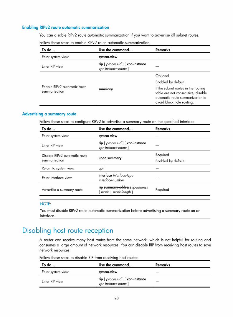
28
Enabling RIPv2 route automatic summarization
You can disable RIPv2 route automatic summarization if you want to advertise all subnet routes.
Follow these steps to enable RIPv2 route automatic summarization:
To do… Use the command… Remarks
Enter system view system-view ––
Enter RIP view rip [ process-id ] [ vpn-instance vpn-instance-name ] ––
Enable RIPv2 automatic route summarization summary
Optional
Enabled by default
If the subnet routes in the routing table are not consecutive, disable automatic route summarization to avoid black hole routing.
Advertising a summary route
Follow these steps to configure RIPv2 to advertise a summary route on the specified interface:
To do… Use the command… Remarks
Enter system view system-view ––
Enter RIP view rip [ process-id ] [ vpn-instance vpn-instance-name ] ––
Disable RIPv2 automatic route summarization
undo summary Required
Enabled by default
Return to system view quit —
Enter interface view interface interface-type interface-number —
Advertise a summary route rip summary-address ip-address { mask | mask-length } Required
NOTE:
You must disable RIPv2 route automatic summarization before advertising a summary route on an interface.
Disabling host route reception A router can receive many host routes from the same network, which is not helpful for routing and consumes a large amount of network resources. You can disable RIP from receiving host routes to save network resources.
Follow these steps to disable RIP from receiving host routes:
To do… Use the command… Remarks
Enter system view system-view —
Enter RIP view rip [ process-id ] [ vpn-instance vpn-instance-name ] —

29
To do… Use the command… Remarks
Disable RIP from receiving host routes
undo host-route Required
Enabled by default
NOTE:
RIPv2 can be disabled from receiving host routes, but RIPv1 cannot.
Advertising a default route Under the following conditions, you can configure RIP to advertise a default route with a specified metric to RIP neighbors:
• In RIP view, you can configure all the interfaces of the RIP process to advertise a default route; in interface view, you can configure a RIP interface of the RIP process to advertise a default route. The interface view takes precedence over on the interface.
• If a RIP process is enabled to advertise a default route, to disable an interface of the RIP process from default route advertisement, you can use the rip default-route no-originate command on the interface.
Follow these steps to configure RIP to advertise a default route:
To do… Use the command… Remarks
Enter system view system-view ––
Enter RIP view rip [ process-id ] [ vpn-instance vpn-instance-name ]
––
Enable RIP to advertise a default route
default-route { only | originate } [ cost cost ]
Optional
Not enabled by default
Return to system view quit ––
Enter interface view interface interface-type interface-number ––
Configure the RIP interface to advertise a default route
rip default-route { { only | originate } [ cost cost ] | no-originate }
Optional
By default, a RIP interface can advertise a default route if the RIP process is configured with default route advertisement.
NOTE:
The router enabled to advertise a default route does not receive default routes from RIP neighbors.
Configuring inbound or outbound route filtering The device supports route filtering. You can filter routes by configuring the inbound and outbound route filtering policies by referencing an ACL or IP prefix list. You can also configure the router to receive only routes from a specified neighbor.
Follow these steps to configure route filtering:

30
To do… Use the command… Remarks
Enter system view system-view ––
Enter RIP view rip [ process-id ] [ vpn-instance vpn-instance-name ] ––
Configure the filtering of incoming routes
filter-policy { acl-number | gateway ip-prefix-name | ip-prefix ip-prefix-name [ gateway ip-prefix-name ] } import [ interface-type interface-number ]
Required
Not configured by default
Configure the filtering of outgoing routes
filter-policy { acl-number | ip-prefix ip-prefix-name } export [ protocol [ process-id ] | interface-type interface-number ]
Required
Not configured by default
NOTE:
• Using the filter-policy import command filters incoming routes. Routes not passing the filtering will be neither installed into the routing table nor advertised to neighbors.
• Using the filter-policy export command filters outgoing routes, including routes redistributed with the import-route command.
Configuring a priority for RIP Multiple IGP protocols can run in a router. If you want RIP routes to have a higher priority than those learned by other routing protocols, then assign RIP a smaller priority value to influence optimal route selection.
Follow these steps to configure a priority for RIP:
To do… Use the command… Remarks
Enter system view system-view ––
Enter RIP view rip [ process-id ] [ vpn-instance vpn-instance-name ] ––
Configure a priority for RIP preference [ route-policy route-policy-name ] value
Optional
100 by default
Configuring RIP route redistribution If a router runs RIP and other routing protocols, you can configure RIP to redistribute OSPF, IS-IS, BGP, static, or direct routes.
Follow these steps to configure RIP route redistribution:
To do… Use the command… Remarks
Enter system view system-view ––
Enter RIP view rip [ process-id ] [ vpn-instance vpn-instance-name ] ––

31
To do… Use the command… Remarks
Configure a default metric for redistributed routes default cost value
Optional
The default metric of a redistributed route is 0.
Redistribute routes from another protocol
import-route protocol [ process-id | all-processes | allow-ibgp ] [ cost cost | route-policy route-policy-name | tag tag ] *
Required
No redistribution is configured by default.
NOTE:
Only active routes can be redistributed. Use the display ip routing-table protocol command to display route state information.
Tuning and optimizing RIP networks Complete the following tasks before tuning and optimizing RIP networks:
• Configure network addresses for interfaces, and make neighboring nodes reachable to each other
• Configure RIP basic functions
Configuring RIP timers You can change the RIP network convergence speed by adjusting RIP timers.
Follow these steps to configure RIP timers:
To do… Use the command… Remarks
Enter system view system-view ––
Enter RIP view rip [ process-id ] [ vpn-instance vpn-instance-name ] ––
Configure values for RIP timers
timers { garbage-collect garbage-collect-value | suppress suppress-value | timeout timeout-value | update update-value } *
Optional
The default update timer, timeout timer, suppress timer, and garbage-collect timer are 30s, 180s, 120s and 120s respectively.
NOTE:
Based on network performance, make RIP timers of RIP routers identical to each other to avoid unnecessary traffic or route oscillation.
Configuring split horizon and poison reverse
NOTE:
If both split horizon and poison reverse are configured, only the poison reverse function takes effect.
The split horizon and poison reverse functions can avoid routing loops.

32
Enabling split horizon
The split horizon function disables an interface from sending routes received from the interface to prevent routing loops between adjacent routers.
Follow these steps to enable split horizon:
To do… Use the command… Remarks
Enter system view system-view —
Enter interface view interface interface-type interface-number —
Enable split horizon rip split-horizon Optional
Enabled by default
Enabling poison reverse
The poison reverse function allows an interface to advertise the routes received from it, but the metric of these routes is set to 16, making them unreachable. This can avoid routing loops between neighbors.
Follow these steps to enable poison reverse:
To do… Use the command… Remarks
Enter system view system-view —
Enter interface view interface interface-type interface-number —
Enable poison reverse rip poison-reverse Required
Disabled by default
Configuring the maximum number of load balanced routes This task allows you to implement load balancing over multiple equal-cost RIP routes.
Follow these steps to configure the maximum number of load balanced routes:
To do… Use the command… Remarks
Enter system view system-view ––
Enter RIP view rip [ process-id ] [ vpn-instance vpn-instance-name ] ––
Configure the maximum number of load balanced routes
maximum load-balancing number Optional
8 by default
Enabling zero field check on incoming RIPv1 messages Some fields in the RIPv1 message must be zero. These fields are called “zero fields.” You can enable zero field check on received RIPv1 messages. If such a field contains a non-zero value, the RIPv1 message will not be processed. If you are certain that all messages are trustworthy, then disable zero field check to save CPU resources.
This feature does not apply to RIPv2 packets, because they have no zero fields.
Follow these steps to enable zero field check on incoming RIPv1 messages:

33
To do… Use the command… Remarks
Enter system view system-view ––
Enter RIP view rip [ process-id ] [ vpn-instance vpn-instance-name ] ––
Enable zero field check on received RIPv1 messages checkzero
Optional
Enabled by default
Enabling source IP address check on incoming RIP updates You can enable source IP address check on incoming RIP updates.
For a message received on an Ethernet interface, RIP compares the source IP address of the message with the IP address of the interface. If they are not in the same network segment, RIP discards the message.
Follow these steps to enable source IP address check on incoming RIP updates:
To do… Use the command… Remarks
Enter system view system-view ––
Enter RIP view rip [ process-id ] [ vpn-instance vpn-instance-name ] ––
Enable source IP address check on incoming RIP messages validate-source-address
Optional
Enabled by default
NOTE:
The source IP address check feature should be disabled if the RIP neighbor is not directly connected.
Configuring RIPv2 message authentication In a network requiring high security, configure this task to implement RIPv2 message validity check and authentication.
RIPv2 supports two authentication modes: plain text and MD5.
In plain text authentication, the authentication information is sent with the RIP message; however, this cannot meet high security needs.
Follow these steps to configure RIPv2 message authentication:
To do… Use the command… Remarks
Enter system view system-view ––
Enter interface view interface interface-type interface-number
––
Configure RIPv2 authentication
rip authentication-mode { md5 { rfc2082 key-string key-id | rfc2453 key-string } | simple password }
Required

34
NOTE:
This feature does not apply to RIPv1 because RIPv1 does not support authentication. Although you can specify an authentication mode for RIPv1 in interface view, the configuration does not take effect.
Specifying a RIP neighbor Usually, RIP sends messages to broadcast or multicast addresses. On non-broadcast or multicast links, you must manually specify RIP neighbors.
Follow these steps to specify a RIP neighbor:
To do… Use the command… Remarks
Enter system view system-view ––
Enter RIP view rip [ process-id ] [ vpn-instance vpn-instance-name ] ––
Specify a RIP neighbor peer ip-address Required
Disable source address check on incoming RIP updates
undo validate-source-address Required
Not disabled by default
NOTE:
• Do not use the peer ip-address command when the neighbor is directly connected because the neighbor may receive both the unicast and multicast (or broadcast) of the same routing information.
• If a specified neighbor is not directly connected, then disable the source address check on incoming updates.
Configuring RIP-to-MIB binding This task allows you to enable a specific RIP process to receive SNMP requests.
Follow these steps to bind RIP to MIB:
To do… Use the command… Remarks
Enter system view system-view ––
Bind RIP to MIB rip mib-binding process-id Optional
By default, MIB is bound to RIP process 1.
Configuring the RIP packet sending rate RIP periodically sends routing information in RIP packets to RIP neighbors.
Sending large numbers of RIP packets at the same time may affect device performance and consume large network bandwidth. To solve this problem, specify the maximum number of RIP packets that can be sent at the specified interval.
Follow these steps to configure the RIP packet sending rate:
To do… Use the command… Remarks
Enter system view system-view ––

35
To do… Use the command… Remarks
Enable a RIP process and enter RIP view
rip [ process-id ] [ vpn-instance vpn-instance-name ] ––
Configure the maximum number of RIP packets that can be sent at the specified interval
output-delay time count count
Optional
By default, an interface sends up to three RIP packets every 20 milliseconds.
Configuring RIP FRR
NOTE:
• RIP FRR is only effective for non-recursive RIP routes (that are learned from directly connected neighbors).
• Do not use RIP FRR and BFD (for RIP) at the same time; otherwise, RIP FRR may fail to take effect.
When a link in a RIP network fails, the traffic is interrupted until RIP completes routing convergence based on the new network topology.
You can enable RIP fast reroute (FRR) to reduce traffic recovery time.
Figure 9 Network diagram for RIP FRR
In Figure 9, after you enable FRR on Router B, RIP designates a backup next hop using a routing policy when a network failure is detected. Packets are directed to the backup next hop to reduce traffic recovery time. At the same time, RIP calculates the shortest path based on the new network topology, and forwards packets over the path after network convergence.
Configuration prerequisites
You need to specify a next hop by using the apply fast-reroute backup-interface command in a routing policy and reference the routing policy with RIP FRR. For more information about routing policy configuration, see the chapter “Routing policy configuration.”
Configuration procedure
Follow these steps to configure RIP FRR:
To do… Use the command… Remarks
Enter system view system-view —
Configure the source address of echo packets bfd echo-source-ip ip-address
Required
Not configured by default.

36
To do… Use the command… Remarks
Enter RIP view rip [ process-id ] [ vpn-instance vpn-instance-name ]
—
Enable RIP FRR and reference a routing policy to designate a backup next hop
fast-reroute route-policy route-policy-name
Required
Disabled by default.
Configuring BFD for RIP
NOTE:
For more information about BFD, see High Availability Configuration Guide.
BFD for RIP provides the following link detection modes:
• Single-hop detection in BFD echo packet mode for a directly connected neighbor. In this mode, a BFD session is established only when the neighbor has route information to send.
• Bidirectional detection in BFD control packet mode for an indirectly connected neighbor. In this mode, a BFD session is established only when both ends have routes to send and BFD is enabled on the receiving interface.
Single-hop detection in BFD echo packet mode Follow these steps to configure BFD for RIP (single-hop detection in BFD echo packet mode):
To do… Use the command… Remarks
Enter system view system-view —
Configure the source IP address of BFD echo packets bfd echo-source-ip ip-address
Required
By default, no source IP address is configured for BFD echo packets.
Enter interface view interface interface-type interface-number
—
Enable BFD on the RIP interface rip bfd enable Required
Disabled by default.
Bidirectional detection in BFD control packet mode Follow these steps to configure BFD for RIP (bidirectional detection in BFD control packet mode):
To do… Use the command… Remarks
Enter system view system-view —
Create a RIP process and enter RIP view
rip [ process-id ] [ vpn-instance vpn-instance-name ]
Required
By default, RIP is disabled.

37
To do… Use the command… Remarks
Specify a RIP neighbor peer ip-address Required
By default, RIP does not unicast updates to any peer.
Enter interface view interface interface-type interface-number —
Enable BFD on the RIP interface rip bfd enable Required
Disabled by default
NOTE:
• Unidirectional detection in BFD echo packet mode only works for RIP neighbors that are directly connected (one hop away from each other).
• Using the undo peer command does not remove the neighbor relationship at once; therefore, it cannotbring down the BFD session at once.
Displaying and maintaining RIP To do… Use the command… Remarks
Display RIP current status and configuration information
display rip [ process-id | vpn-instance vpn-instance-name ] [ | { begin | exclude | include } regular-expression ]
Available in any view
Display all active routes in RIP database
display rip process-id database [ | { begin | exclude | include } regular-expression ]
Display RIP interface information
display rip process-id interface [ interface-type interface-number ] [ | { begin | exclude | include } regular-expression ]
Display routing information about a specified RIP process
display rip process-id route [ ip-address { mask | mask-length } | peer ip-address | statistics ] [ | { begin | exclude | include } regular-expression ]
Reset a RIP process reset rip process-id process Available in user view
Clear the statistics of a RIP process reset rip process-id statistics
RIP configuration examples
Configuring RIP version Network requirements
As shown in Figure 10, enable RIPv2 on all interfaces on Switch A and Switch B.

38
Figure 10 Network diagram
Configuration procedure
1. Configure an IP address for each interface. (Details not shown)
2. Configure basic RIP functions.
# Configure Switch A. [SwitchA] rip
[SwitchA-rip-1] network 192.168.1.0
[SwitchA-rip-1] network 172.16.0.0
[SwitchA-rip-1] network 172.17.0.0
# Configure Switch B. [SwitchB] rip
[SwitchB-rip-1] network 192.168.1.0
[SwitchB-rip-1] network 10.0.0.0
# Display the RIP routing table of Switch A. [SwitchA] display rip 1 route
Route Flags: R - RIP, T - TRIP
P - Permanent, A - Aging, S - Suppressed, G - Garbage-collect
----------------------------------------------------------------------------
Peer 192.168.1.2 on Vlan-interface100
Destination/Mask Nexthop Cost Tag Flags Sec
10.0.0.0/8 192.168.1.2 1 0 RA 11
The output shows that RIPv1 uses a natural mask.
3. Configure RIP version.
# Configure RIPv2 on Switch A. [SwitchA] rip
[SwitchA-rip-1] version 2
[SwitchA-rip-1] undo summary
# Configure RIPv2 on Switch B. [SwitchB] rip
[SwitchB-rip-1] version 2
[SwitchB-rip-1] undo summary
# Display the RIP routing table on Switch A. [SwitchA] display rip 1 route
Route Flags: R - RIP, T - TRIP
P - Permanent, A - Aging, S - Suppressed, G - Garbage-collect
----------------------------------------------------------------------------
Peer 192.168.1.2 on Vlan-interface100
Destination/Mask Nexthop Cost Tag Flags Sec

39
10.0.0.0/8 192.168.1.2 1 0 RA 50
10.2.1.0/24 192.168.1.2 1 0 RA 16
10.1.1.0/24 192.168.1.2 1 0 RA 16
The output shows that RIPv2 uses classless subnet mask.
NOTE:
RIPv1 routing information has a long aging time, so it will exist until it ages out after RIPv2 is configured.
Configuring RIP route redistribution Network requirements
In the following figure, two RIP processes are running on Switch B, which communicates with Switch A through RIP 100 and with Switch C through RIP 200.
Configure route redistribution on Switch B to make RIP 200 redistribute direct routes and routes from RIP 100. Switch C can then learn routes destined for 10.2.1.0/24 and 11.1.1.0/24, and Switch A cannot learn routes destined for 12.3.1.0/24 and 16.4.1.0/24.
Configure a filtering policy on Switch B to filter out the route 10.2.1.1/24 from RIP 100, making the route not advertised to Switch C.
Figure 11 Network diagram
Configuration procedure
1. Configure an IP address for each interface. (Details not shown)
2. Configure basic RIP functions.
# Enable RIP 100 and specify RIP version 2 on Switch A. <SwitchA> system-view
[SwitchA] rip 100
[SwitchA-rip-100] network 10.0.0.0
[SwitchA-rip-100] network 11.0.0.0
[SwitchA-rip-100] version 2
[SwitchA-rip-100] undo summary
[SwitchA-rip-100] quit
# Enable RIP 100 and RIP 200 and specify RIP version 2 on Switch B. <SwitchB> system-view
[SwitchB] rip 100
[SwitchB-rip-100] network 11.0.0.0
[SwitchB-rip-100] version 2
[SwitchB-rip-100] undo summary
[SwitchB-rip-100] quit

40
[SwitchB] rip 200
[SwitchB-rip-200] network 12.0.0.0
[SwitchB-rip-200] version 2
[SwitchB-rip-200] undo summary
[SwitchB-rip-200] quit
# Enable RIP 200 and specify RIP version 2 on Switch C. <SwitchC> system-view
[SwitchC] rip 200
[SwitchC-rip-200] network 12.0.0.0
[SwitchC-rip-200] network 16.0.0.0
[SwitchC-rip-200] version 2
[SwitchC-rip-200] undo summary
# Display the routing table of Switch C. [SwitchC] display ip routing-table
Routing Tables: Public
Destinations : 6 Routes : 6
Destination/Mask Proto Pre Cost NextHop Interface
12.3.1.0/24 Direct 0 0 12.3.1.2 Vlan200
12.3.1.2/32 Direct 0 0 127.0.0.1 InLoop0
16.4.1.0/24 Direct 0 0 16.4.1.1 Vlan400
16.4.1.1/32 Direct 0 0 127.0.0.1 InLoop0
127.0.0.0/8 Direct 0 0 127.0.0.1 InLoop0
127.0.0.1/32 Direct 0 0 127.0.0.1 InLoop0
3. Configure route redistribution.
# On Switch B, configure RIP 200 to redistribute direct routes and routes from RIP 100. [SwitchB] rip 200
[SwitchB-rip-200] import-route rip 100
[SwitchB-rip-200] import-route direct
[SwitchB-rip-200] quit
# Display the routing table of Switch C. [SwitchC] display ip routing-table
Routing Tables: Public
Destinations : 8 Routes : 8
Destination/Mask Proto Pre Cost NextHop Interface
10.2.1.0/24 RIP 100 1 12.3.1.1 Vlan200
11.1.1.0/24 RIP 100 1 12.3.1.1 Vlan200
12.3.1.0/24 Direct 0 0 12.3.1.2 Vlan200
12.3.1.2/32 Direct 0 0 127.0.0.1 InLoop0
16.4.1.0/24 Direct 0 0 16.4.1.1 Vlan400
16.4.1.1/32 Direct 0 0 127.0.0.1 InLoop0
127.0.0.0/8 Direct 0 0 127.0.0.1 InLoop0
127.0.0.1/32 Direct 0 0 127.0.0.1 InLoop0
4. Configure an filtering policy to filter redistributed routes.
# Define ACL 2000 and reference it to a filtering policy to filter routes redistributed from RIP 100 on Switch B, making the route not advertised to Switch C. [SwitchB] acl number 2000

41
[SwitchB-acl-basic-2000] rule deny source 10.2.1.1 0.0.0.255
[SwitchB-acl-basic-2000] rule permit
[SwitchB-acl-basic-2000] quit
[SwitchB] rip 200
[SwitchB-rip-200] filter-policy 2000 export rip 100
# Display the routing table of Switch C. [SwitchC] display ip routing-table
Routing Tables: Public
Destinations : 7 Routes : 7
Destination/Mask Proto Pre Cost NextHop Interface
11.1.1.0/24 RIP 100 1 12.3.1.1 Vlan200
12.3.1.0/24 Direct 0 0 12.3.1.2 Vlan200
12.3.1.2/32 Direct 0 0 127.0.0.1 InLoop0
16.4.1.0/24 Direct 0 0 16.4.1.1 Vlan400
16.4.1.1/32 Direct 0 0 127.0.0.1 InLoop0
127.0.0.0/8 Direct 0 0 127.0.0.1 InLoop0
127.0.0.1/32 Direct 0 0 127.0.0.1 InLoop0
Configuring an additional metric for a RIP interface Network requirements
In the following figure, RIP is enabled on all the interfaces of Switch A, Switch B, Switch C, Switch D, and Switch E. The switches are interconnected through RIPv2.
Switch A has two links to Switch D. The link from Switch B to Switch D is more stable than that from Switch C to Switch D. Configure an additional metric for RIP routes received through VLAN-interface 200 on Switch A so that Switch A prefers the 1.1.5.0/24 network learned from Switch B.
Figure 12 Network diagram
Configuration procedure
1. Configure IP addresses for the interfaces. (Details not shown)
2. Configure RIP basic functions.
# Configure Switch A. <SwitchA> system-view
[SwitchA] rip 1
[SwitchA-rip-1] network 1.0.0.0
[SwitchA-rip-1] version 2
[SwitchA-rip-1] undo summary

42
[SwitchA-rip-1] quit
# Configure Switch B. <SwitchB> system-view
[SwitchB] rip 1
[SwitchB-rip-1] network 1.0.0.0
[SwitchB-rip-1] version 2
[SwitchB-rip-1] undo summary
# Configure Switch C. <SwitchC> system-view
[SwitchB] rip 1
[SwitchC-rip-1] network 1.0.0.0
[SwitchC-rip-1] version 2
[SwitchC-rip-1] undo summary
# Configure Switch D. <SwitchD> system-view
[SwitchD] rip 1
[SwitchD-rip-1] network 1.0.0.0
[SwitchD-rip-1] version 2
[SwitchD-rip-1] undo summary
# Configure Switch E. <SwitchE> system-view
[SwitchE] rip 1
[SwitchE-rip-1] network 1.0.0.0
[SwitchE-rip-1] version 2
[SwitchE-rip-1] undo summary
# Display the IP routing table of Switch A. [SwitchA] display rip 1 database
1.0.0.0/8, cost 0, ClassfulSumm
1.1.1.0/24, cost 0, nexthop 1.1.1.1, Rip-interface
1.1.2.0/24, cost 0, nexthop 1.1.2.1, Rip-interface
1.1.3.0/24, cost 1, nexthop 1.1.1.2
1.1.4.0/24, cost 1, nexthop 1.1.2.2
1.1.5.0/24, cost 2, nexthop 1.1.1.2
1.1.5.0/24, cost 2, nexthop 1.1.2.2
The output shows that two RIP routes can reach network 1.1.5.0/24. Their next hops are Switch B (1.1.1.2) and Switch C (1.1.2.2) respectively, with the same cost of 2. Switch C is the next hop router to reach network 1.1.4.0/24, with a cost of 1.
3. Configure an additional metric for the RIP interface.
# Configure an additional metric of 3 for VLAN-interface 200 on Switch A. [SwitchA] interface vlan-interface 200
[SwitchA-Vlan-interface200] rip metricin 3
[SwitchA-Vlan-interface200] display rip 1 database
1.0.0.0/8, cost 0, ClassfulSumm
1.1.1.0/24, cost 0, nexthop 1.1.1.1, Rip-interface
1.1.2.0/24, cost 0, nexthop 1.1.2.1, Rip-interface
1.1.3.0/24, cost 1, nexthop 1.1.1.2

43
1.1.4.0/24, cost 2, nexthop 1.1.1.2
1.1.5.0/24, cost 2, nexthop 1.1.1.2
The output shows that only one RIP route reaches network 1.1.5.0/24, with the next hop as Switch B (1.1.1.2) and a cost of 2.
Configuring RIP to advertise a summary route Network requirements
In the following figure, Switch A and Switch B run OSPF, Switch D runs RIP, and Switch C runs OSPF and RIP.
Configure RIP to redistribute OSPF routes on Switch C so that Switch D has routes destined for networks 10.1.1.0/24, 10.2.1.0/24, 10.5.1.0/24, and 10.6.1.0/24.
Configure route summarization on Switch C and advertise only the summary route 10.0.0.0/8, reducing the routing table size of Switch D.
Figure 13 Network diagram
Configuration procedure
1. Configure IP addresses for interfaces. (Details not shown)
2. Configure OSPF basic functions.
# Configure Switch A. <SwitchA> system-view
[SwitchA] ospf
[SwitchA-ospf-1] area 0
[SwitchA-ospf-1-area-0.0.0.0] network 10.5.1.0 0.0.0.255
[SwitchA-ospf-1-area-0.0.0.0] network 10.2.1.0 0.0.0.255
[SwitchA-ospf-1-area-0.0.0.0] quit
# Configure Switch B. <SwitchB> system-view
[SwitchB] ospf
[SwitchB-ospf-1] area 0
[SwitchB-ospf-1-area-0.0.0.0] network 10.1.1.0 0.0.0.255
[SwitchB-ospf-1-area-0.0.0.0] network 10.6.1.0 0.0.0.255
[SwitchB-ospf-1-area-0.0.0.0] quit
# Configure Switch C.

44
<SwitchC> system-view
[SwitchC] ospf
[SwitchC-ospf-1] area 0
[SwitchC-ospf-1-area-0.0.0.0] network 10.1.1.0 0.0.0.255
[SwitchC-ospf-1-area-0.0.0.0] network 10.2.1.0 0.0.0.255
[SwitchC-ospf-1-area-0.0.0.0] quit
3. Configure RIP basic functions.
# Configure Switch C. <SwitchC> system-view
[SwitchC] rip 1
[SwitchC-rip-1] network 11.3.1.0
[SwitchC-rip-1] version 2
[SwitchC-rip-1] undo summary
# Configure Switch D. <SwitchD> system-view
[SwitchD] rip 1
[SwitchD-rip-1] network 11.0.0.0
[SwitchD-rip-1] version 2
[SwitchD-rip-1] undo summary
[SwitchD-rip-1] quit
# Configure RIP to redistribute the routes from OSPF process 1 and direct routes on Switch C. [SwitchC-rip-1] import-route direct
[SwitchC-rip-1] import-route ospf 1
# Display the routing table information of Switch D. [SwitchD] display ip routing-table
Routing Tables: Public
Destinations : 10 Routes : 10
Destination/Mask Proto Pre Cost NextHop Interface
10.1.1.0/24 RIP 100 1 11.3.1.1 Vlan300
10.2.1.0/24 RIP 100 1 11.3.1.1 Vlan300
10.5.1.0/24 RIP 100 1 11.3.1.1 Vlan300
10.6.1.0/24 RIP 100 1 11.3.1.1 Vlan300
11.3.1.0/24 Direct 0 0 11.3.1.2 Vlan300
11.3.1.2/32 Direct 0 0 127.0.0.1 InLoop0
11.4.1.0/24 Direct 0 0 11.4.1.2 Vlan400
11.4.1.2/32 Direct 0 0 127.0.0.1 InLoop0
127.0.0.0/8 Direct 0 0 127.0.0.1 InLoop0
127.0.0.1/32 Direct 0 0 127.0.0.1 InLoop0
4. Configure route summarization on Switch C and advertise only the summary route 10.0.0.0/8. [SwitchC] interface vlan-interface 300
[SwitchC-Vlan-interface300] rip summary-address 10.0.0.0 8
# Display the routing table information of Switch D. [SwitchD] display ip routing-table
Routing Tables: Public
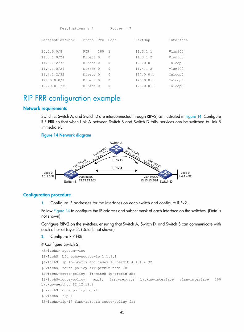
45
Destinations : 7 Routes : 7
Destination/Mask Proto Pre Cost NextHop Interface
10.0.0.0/8 RIP 100 1 11.3.1.1 Vlan300
11.3.1.0/24 Direct 0 0 11.3.1.2 Vlan300
11.3.1.2/32 Direct 0 0 127.0.0.1 InLoop0
11.4.1.0/24 Direct 0 0 11.4.1.2 Vlan400
11.4.1.2/32 Direct 0 0 127.0.0.1 InLoop0
127.0.0.0/8 Direct 0 0 127.0.0.1 InLoop0
127.0.0.1/32 Direct 0 0 127.0.0.1 InLoop0
RIP FRR configuration example Network requirements
Switch S, Switch A, and Switch D are interconnected through RIPv2, as illustrated in Figure 14. Configure RIP FRR so that when Link A between Switch S and Switch D fails, services can be switched to Link B immediately.
Figure 14 Network diagram
Switch S Switch D
Switch A
Loop 01.1.1.1/32
Vlan-int100
12.12.12.1/24
Vlan-int20013.13.13.1/24
Vlan-int20013.13.13.2/24
Vlan-int100
12.12.12.2/24Vlan-int101
24.24.24.2/24 Vlan-int101
24.24.24.4/24Loop 0
4.4.4.4/32
Link A
Link B
Configuration procedure
1. Configure IP addresses for the interfaces on each switch and configure RIPv2.
Follow Figure 14 to configure the IP address and subnet mask of each interface on the switches. (Details not shown)
Configure RIPv2 on the switches, ensuring that Switch A, Switch D, and Switch S can communicate with each other at Layer 3. (Details not shown)
2. Configure RIP FRR.
# Configure Switch S. <SwitchS> system-view
[SwitchS] bfd echo-source-ip 1.1.1.1
[SwitchS] ip ip-prefix abc index 10 permit 4.4.4.4 32
[SwitchS] route-policy frr permit node 10
[SwitchS-route-policy] if-match ip-prefix abc
[SwitchS-route-policy] apply fast-reroute backup-interface vlan-interface 100 backup-nexthop 12.12.12.2
[SwitchS-route-policy] quit
[SwitchS] rip 1
[SwitchS-rip-1] fast-reroute route-policy frr
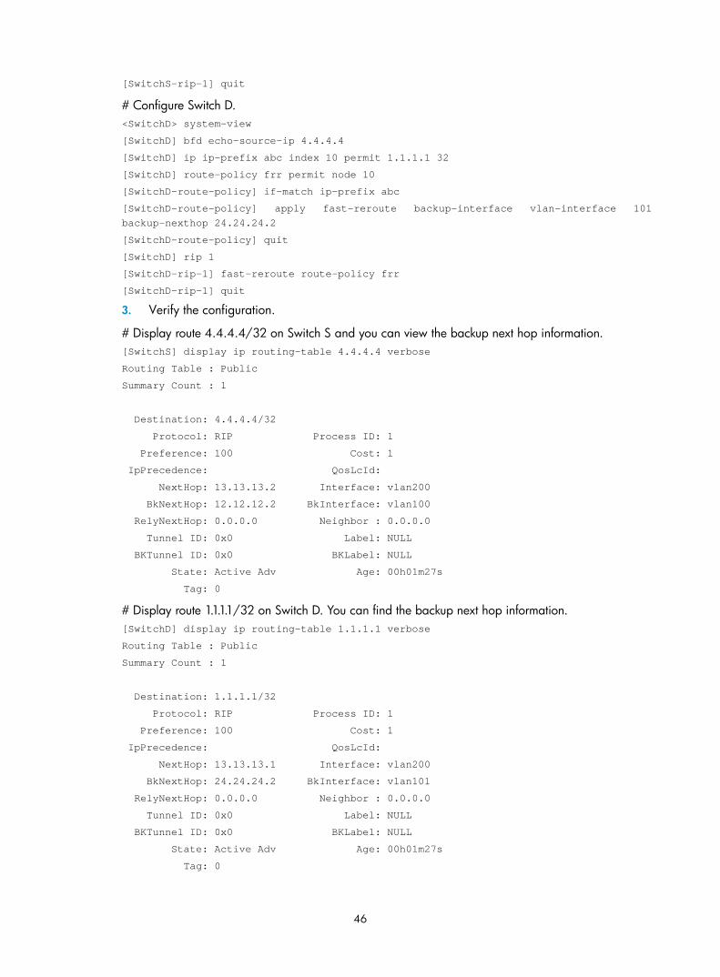
46
[SwitchS-rip-1] quit
# Configure Switch D. <SwitchD> system-view
[SwitchD] bfd echo-source-ip 4.4.4.4
[SwitchD] ip ip-prefix abc index 10 permit 1.1.1.1 32
[SwitchD] route-policy frr permit node 10
[SwitchD-route-policy] if-match ip-prefix abc
[SwitchD-route-policy] apply fast-reroute backup-interface vlan-interface 101 backup-nexthop 24.24.24.2
[SwitchD-route-policy] quit
[SwitchD] rip 1
[SwitchD-rip-1] fast-reroute route-policy frr
[SwitchD-rip-1] quit
3. Verify the configuration.
# Display route 4.4.4.4/32 on Switch S and you can view the backup next hop information. [SwitchS] display ip routing-table 4.4.4.4 verbose
Routing Table : Public
Summary Count : 1
Destination: 4.4.4.4/32
Protocol: RIP Process ID: 1
Preference: 100 Cost: 1
IpPrecedence: QosLcId:
NextHop: 13.13.13.2 Interface: vlan200
BkNextHop: 12.12.12.2 BkInterface: vlan100
RelyNextHop: 0.0.0.0 Neighbor : 0.0.0.0
Tunnel ID: 0x0 Label: NULL
BKTunnel ID: 0x0 BKLabel: NULL
State: Active Adv Age: 00h01m27s
Tag: 0
# Display route 1.1.1.1/32 on Switch D. You can find the backup next hop information. [SwitchD] display ip routing-table 1.1.1.1 verbose
Routing Table : Public
Summary Count : 1
Destination: 1.1.1.1/32
Protocol: RIP Process ID: 1
Preference: 100 Cost: 1
IpPrecedence: QosLcId:
NextHop: 13.13.13.1 Interface: vlan200
BkNextHop: 24.24.24.2 BkInterface: vlan101
RelyNextHop: 0.0.0.0 Neighbor : 0.0.0.0
Tunnel ID: 0x0 Label: NULL
BKTunnel ID: 0x0 BKLabel: NULL
State: Active Adv Age: 00h01m27s
Tag: 0
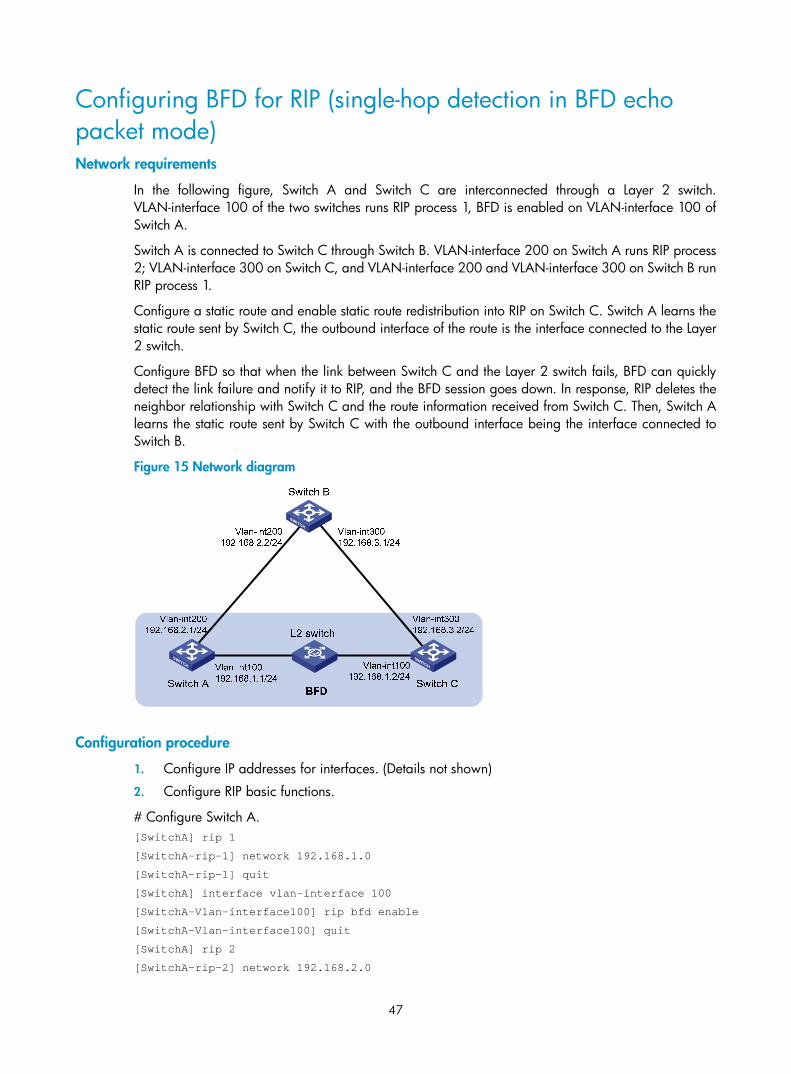
47
Configuring BFD for RIP (single-hop detection in BFD echo packet mode) Network requirements
In the following figure, Switch A and Switch C are interconnected through a Layer 2 switch. VLAN-interface 100 of the two switches runs RIP process 1, BFD is enabled on VLAN-interface 100 of Switch A.
Switch A is connected to Switch C through Switch B. VLAN-interface 200 on Switch A runs RIP process 2; VLAN-interface 300 on Switch C, and VLAN-interface 200 and VLAN-interface 300 on Switch B run RIP process 1.
Configure a static route and enable static route redistribution into RIP on Switch C. Switch A learns the static route sent by Switch C, the outbound interface of the route is the interface connected to the Layer 2 switch.
Configure BFD so that when the link between Switch C and the Layer 2 switch fails, BFD can quickly detect the link failure and notify it to RIP, and the BFD session goes down. In response, RIP deletes the neighbor relationship with Switch C and the route information received from Switch C. Then, Switch A learns the static route sent by Switch C with the outbound interface being the interface connected to Switch B.
Figure 15 Network diagram
Configuration procedure
1. Configure IP addresses for interfaces. (Details not shown)
2. Configure RIP basic functions.
# Configure Switch A. [SwitchA] rip 1
[SwitchA-rip-1] network 192.168.1.0
[SwitchA-rip-1] quit
[SwitchA] interface vlan-interface 100
[SwitchA-Vlan-interface100] rip bfd enable
[SwitchA-Vlan-interface100] quit
[SwitchA] rip 2
[SwitchA-rip-2] network 192.168.2.0

48
# Configure Switch B. [SwitchB] rip 1
[SwitchB-rip-1] network 192.168.2.0
[SwitchB-rip-1] network 192.168.3.0
[SwitchB-rip-1] quit
# Configure Switch C. [SwitchC] rip 1
[SwitchC-rip-1] network 192.168.1.0
[SwitchC-rip-1] network 192.168.3.0
[SwitchC-rip-1] import-route static
[SwitchC-rip-1] quit
3. Configure BFD parameters.
# Configure Switch A. [SwitchA] bfd session init-mode active
[SwitchA] bfd echo-source-ip 11.11.11.11
[SwitchA] interface vlan-interface 100
[SwitchA-Vlan-interface100] bfd min-transmit-interval 500
[SwitchA-Vlan-interface100] bfd min-receive-interval 500
[SwitchA-Vlan-interface100] bfd detect-multiplier 7
[SwitchA-Vlan-interface100] quit
[SwitchA] quit
4. Configure a static route on Switch C. [SwitchC] ip route-static 100.1.1.1 24 null 0
5. Verify the configuration.
# Display the BFD session information of Switch A. <SwitchA> display bfd session
Total Session Num: 1 Init Mode: Active
Session Working Under Echo Mode:
LD SourceAddr DestAddr State Holdtime Interface
5 192.168.1.1 192.168.1.2 Up 2000ms Vlan100
# Display the RIP route 100.1.1.0/24 learned by Switch A. <SwitchA> display ip routing-table 100.1.1.0 24 verbose
Routing Table : Public
Summary Count : 2
Destination: 100.1.1.0/24
Protocol: RIP Process ID: 1
Preference: 100 Cost: 1
IpPrecedence: QosLcId:
NextHop: 192.168.1.2 Interface: vlan-interface 100
BkNextHop: 0.0.0.0 BkInterface:
RelyNextHop: 0.0.0.0 Neighbor : 192.168.1.2
Tunnel ID: 0x0 Label: NULL
BKTunnel ID: 0x0 BKLabel: NULL
State: Active Adv Age: 00h00m47s
Tag: 0
Destination: 100.1.1.0/24
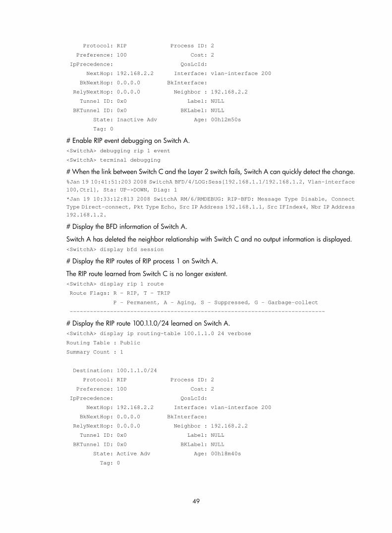
49
Protocol: RIP Process ID: 2
Preference: 100 Cost: 2
IpPrecedence: QosLcId:
NextHop: 192.168.2.2 Interface: vlan-interface 200
BkNextHop: 0.0.0.0 BkInterface:
RelyNextHop: 0.0.0.0 Neighbor : 192.168.2.2
Tunnel ID: 0x0 Label: NULL
BKTunnel ID: 0x0 BKLabel: NULL
State: Inactive Adv Age: 00h12m50s
Tag: 0
# Enable RIP event debugging on Switch A. <SwitchA> debugging rip 1 event
<SwitchA> terminal debugging
# When the link between Switch C and the Layer 2 switch fails, Switch A can quickly detect the change. %Jan 19 10:41:51:203 2008 SwitchA BFD/4/LOG:Sess[192.168.1.1/192.168.1.2, Vlan-interface 100,Ctrl], Sta: UP->DOWN, Diag: 1
*Jan 19 10:33:12:813 2008 SwitchA RM/6/RMDEBUG: RIP-BFD: Message Type Disable, Connect Type Direct-connect, Pkt Type Echo, Src IP Address 192.168.1.1, Src IFIndex4, Nbr IP Address 192.168.1.2.
# Display the BFD information of Switch A.
Switch A has deleted the neighbor relationship with Switch C and no output information is displayed. <SwitchA> display bfd session
# Display the RIP routes of RIP process 1 on Switch A.
The RIP route learned from Switch C is no longer existent. <SwitchA> display rip 1 route
Route Flags: R - RIP, T - TRIP
P - Permanent, A - Aging, S - Suppressed, G - Garbage-collect
----------------------------------------------------------------------------
# Display the RIP route 100.1.1.0/24 learned on Switch A. <SwitchA> display ip routing-table 100.1.1.0 24 verbose
Routing Table : Public
Summary Count : 1
Destination: 100.1.1.0/24
Protocol: RIP Process ID: 2
Preference: 100 Cost: 2
IpPrecedence: QosLcId:
NextHop: 192.168.2.2 Interface: vlan-interface 200
BkNextHop: 0.0.0.0 BkInterface:
RelyNextHop: 0.0.0.0 Neighbor : 192.168.2.2
Tunnel ID: 0x0 Label: NULL
BKTunnel ID: 0x0 BKLabel: NULL
State: Active Adv Age: 00h18m40s
Tag: 0

50
Configuring BFD for RIP (bidirectional detection in BFD control packet mode) Network requirements
In the following figure, Switch A is connected to Switch C through Switch B. VLAN-interface 100 on Switch A, VLAN-interface 200 on Switch C, and VLAN-interface 200 and VLAN-interface 100 on Switch B run RIP process 1.
Configure a static route to Switch C on Switch A, and configure a static route to Switch A on Switch C. Enable BFD on VLAN-interface 100 of Switch A and VLAN-interface 200 of Switch C.
Switch A is connected to Switch C through Switch D. VLAN-interface 300 on Switch A runs RIP process 2; VLAN-interface 400 on Switch C, and VLAN-interface 300 and VLAN-interface 400 on Switch D run RIP process 1.
Enable static route redistribution into RIP on Switch A and Switch C so that Switch A and Switch C have routes to send to each other. Switch A learns the static route sent by Switch C, the outbound interface is the interface connected to Switch B.
Configure BFD so that when the link between Switch B and Switch C fails, BFD can quickly detect the link failure and notify it to RIP, and the BFD session goes down. In response, RIP deletes the neighbor relationship with Switch C and the route information received from Switch C. Then, Switch A learns the static route sent by Switch C, the outbound interface of the route is the interface connected to Switch D.
Figure 16 Network diagram
Switch CSwitch A
Vlan-int100192.168.1.1/24
Vlan-int100 192.168.1.2/24
Switch B Vlan-int200192.168.2.1/24
BFD
Vlan-int200 192.168.2.2/24
Switch D
Vlan-int300 192.168.3.2/24
Vlan-int300 192.168.3.1/24
Vlan-int400192.168.4.1/24
Vlan-int400192.168.4.2/24
Configuration procedure
1. Configure IP addresses for interfaces. (Details not shown)
2. Configure RIP basic functions and enable static route redistribution into RIP so that Switch A and Switch C have routes to send to each other.
# Configure Switch A. [SwitchA] rip 1
[SwitchA-rip-1] network 192.168.1.0
[SwitchA-rip-1] peer 192.168.2.2
[SwitchA-rip-1] undo validate-source-address
[SwitchA-rip-1] import-route static

51
[SwitchA-rip-1] quit
[SwitchA] interface vlan-interface 100
[SwitchA-Vlan-interface100] rip bfd enable
[SwitchA-Vlan-interface100] quit
[SwitchA] rip 2
[SwitchA-rip-2] network 192.168.3.0
[SwitchA-rip-2] quit
# Configure Switch C. [SwitchC] rip 1
[SwitchC-rip-1] network 192.168.2.0
[SwitchC-rip-1] network 192.168.4.0
[SwitchC-rip-1] peer 192.168.1.1
[SwitchC-rip-1] undo validate-source-address
[SwitchC-rip-1] import-route static
[SwitchC-rip-1] quit
[SwitchC] interface vlan-interface 200
[SwitchC-Vlan-interface200] rip bfd enable
[SwitchC-Vlan-interface200] quit
# Configure Switch D. <SwitchD> system-view
[SwitchD] rip 1
[SwitchD-rip-1] network 192.168.3.0
[SwitchD-rip-1] network 192.168.4.0
3. Configure BFD parameters.
# Configure Switch A. [SwitchA] bfd session init-mode active
[SwitchA] interface vlan-interface 100
[SwitchA-Vlan-interface100] bfd min-transmit-interval 500
[SwitchA-Vlan-interface100] bfd min-receive-interval 500
[SwitchA-Vlan-interface100] bfd detect-multiplier 7
[SwitchA-Vlan-interface100] quit
# Configure Switch C. [SwitchC] bfd session init-mode active
[SwitchC] interface vlan-interface 200
[SwitchC-Vlan-interface200] bfd min-transmit-interval 500
[SwitchC-Vlan-interface200] bfd min-receive-interval 500
[SwitchC-Vlan-interface200] bfd detect-multiplier 7
[SwitchC-Vlan-interface200] quit
4. Configure static routes.
# Configure a static route to Switch C on Switch A. [SwitchA] ip route-static 192.168.2.0 24 vlan-interface 100 192.168.1.2
[SwitchA] ip route-static 101.1.1.0 24 null 0
[SwitchA] quit
# Configure a static route to Switch A on Switch C. [SwitchC] ip route-static 192.168.1.0 24 vlan-interface 200 192.168.2.1
[SwitchC] ip route-static 100.1.1.0 24 null 0

52
CAUTION:
If you specify null 0 interface as the output interface for a static route, do not specify the IP address of a directly connected network as the destination IP address.
5. Verify the configuration.
# Display the BFD session information of Switch A. <SwitchA> display bfd session
Total Session Num: 1 Init Mode: Active
Session Working Under Ctrl Mode:
LD/RD SourceAddr DestAddr State Holdtime Interface
6/3 192.168.1.1 192.168.2.2 Up 1700ms vlan100
# Display the RIP route 100.1.1.0/24 learned on Switch A. <SwitchA> display ip routing-table 100.1.1.0 24 verbose
Routing Table : Public
Summary Count : 2
Destination: 100.1.1.0/24
Protocol: RIP Process ID: 1
Preference: 100 Cost: 1
IpPrecedence: QosLcId:
NextHop: 192.168.1.2 Interface: vlan-interface 100
BkNextHop: 0.0.0.0 BkInterface:
RelyNextHop: 0.0.0.0 Neighbor : 192.168.1.2
Tunnel ID: 0x0 Label: NULL
BKTunnel ID: 0x0 BKLabel: NULL
State: Active Adv Age: 00h00m47s
Tag: 0
Destination: 100.1.1.0/24
Protocol: RIP Process ID: 2
Preference: 100 Cost: 2
IpPrecedence: QosLcId:
NextHop: 192.168.3.2 Interface: vlan-interface 300
BkNextHop: 0.0.0.0 BkInterface:
RelyNextHop: 0.0.0.0 Neighbor : 192.168.3.2
Tunnel ID: 0x0 Label: NULL
BKTunnel ID: 0x0 BKLabel: NULL
State: Inactive Adv Age: 00h12m50s
Tag: 0
# Enable RIP event debugging on Switch A. <SwitchA> debugging rip 1 event
<SwitchA> terminal debugging
# When the link between Switch B and Switch C fails, Switch A quickly detects the link state change. %Jan 19 10:41:51:203 2008 SwitchA BFD/4/LOG:Sess[192.168.1.1/192.168.2.2, Vlan-interface 100, Ctrl], Sta: UP->DOWN, Diag: 1
*Jan 19 10:41:51:203 2008 SwitchA RM/6/RMDEBUG: RIP-BFD: Message Type Disable, Connect Type Indirect-connect, Pkt Type Control, Src IP Address 192.168.1.1, Src IFIndex 4, Nbr IP Address 192.168.2.2.

53
# Display the BFD information of Switch A.
Switch A has deleted the neighbor relationship with Switch C and no output information is displayed. <SwitchA> display bfd session
# Display the RIP routes of RIP process 1 on Switch A.
The RIP route learned from Switch C is no longer existent. <SwitchA> display rip 1 route
Route Flags: R - RIP, T - TRIP
P - Permanent, A - Aging, S - Suppressed, G - Garbage-collect
----------------------------------------------------------------------------
# Display the RIP route 100.1.1.0/24 learned on Switch A. <SwitchA> display ip routing-table 100.1.1.0 24 verbose
Routing Table : Public
Summary Count : 1
Destination: 100.1.1.0/24
Protocol: RIP Process ID: 2
Preference: 100 Cost: 2
IpPrecedence: QosLcId:
NextHop: 192.168.3.2 Interface: vlan-interface 300
BkNextHop: 0.0.0.0 BkInterface:
RelyNextHop: 0.0.0.0 Neighbor : 192.168.3.2
Tunnel ID: 0x0 Label: NULL
BKTunnel ID: 0x0 BKLabel: NULL
State: Active Adv Age: 00h18m40s
Tag: 0
Troubleshooting RIP
No RIP updates received Symptom:
No RIP updates are received when the links function.
Analysis:
After enabling RIP, you must use the network command to enable corresponding interfaces. Ensure no interfaces are disabled from handling RIP messages.
If the peer is configured to send multicast messages, the same must be configured on the local end.
Solution:
• Use the display current-configuration command to check RIP configuration.
• Use the display rip command to check whether an interface is disabled.
Route oscillation occurred Symptom:

54
When all links function, route oscillation occurs on the RIP network. After displaying the routing table, you may find some routes intermittently appear and disappear in the routing table.
Analysis:
In the RIP network, make sure that all the same timers within the entire network are identical and have logical relationships between them. For example, the timeout timer value must be greater than the update timer value.
Solution:
• Use the display rip command to check the configuration of RIP timers.
• Use the timers command to adjust timers properly.
55
OSPF configuration
Open Shortest Path First (OSPF) is a link state interior gateway protocol developed by the OSPF working group of the Internet Engineering Task Force (IETF). Now, OSPF version 2 (RFC 2328) is used.
NOTE:
• Unless otherwise noted, OSPF refers to OSPFv2 throughout this document.
• The term router in this document refers to both routers and Layer 3 switches.
• The 3600 v2 SI Switch Series does not support OSPF.
Introduction to OSPF OSPF has the following features:
• Wide scope—Supports various network sizes and up to several hundred routers in an OSPF routing domain
• Fast convergence—Transmits routing updates instantly upon network topology changes
• Loop-free—Computes routes with the shortest path first (SPF) algorithm to avoid routing loops
• Area-based network partition—Splits an AS into different areas to facilitate management. In addition, routing information transmitted between areas is summarized to reduce traffic and routing table sizes.
• Equal-cost multi-path (ECMP) routing—Supports multiple equal-cost routes to a destination
• Routing hierarchy—Supports a four-level routing hierarchy that prioritizes routes into intra-area, inter-area, external Type-1, and external Type-2 routes
• Authentication—Supports interface-based packet authentication to ensure the security of packet exchange
• Support for multicast—Multicasts protocol packets on some types of links
Basic concepts Autonomous System
An Autonomous System (AS) comprises a group of routers that run the same routing protocol.
OSPF route computation
OSPF computes routes in an area as follows:
• Based on the network topology around itself, each router generates Link State Advertisements (LSAs) and sends them to other routers in update packets.
• Each OSPF router collects LSAs from other routers to compose a link state database (LSDB). An LSA describes the network topology around a router, and the LSDB describes the entire network topology of the AS.
• Each router transforms the LSDB in the area to a weighted directed graph, which is the topology of the entire network. All the routers of the area have the same graph.

56
• Each router uses the SPF algorithm to compute a shortest path tree showing the routes to the nodes in the AS. The router itself is the root of the tree.
Router ID
An OSPF process running on a router must have its own router ID. This ID is a 32-bit unsigned integer that uniquely identifies the router in the AS.
OSPF packets
OSPF uses the following types of packets:
• Hello—Periodically sent to find and maintain neighbors, containing the values of some timers, information about the DR, BDR, and known neighbors.
• Database description (DD)—Describes the digest of each LSA in the LSDB, exchanged between two routers for data synchronization.
• Link state request (LSR)—Requests needed LSAs from the neighbor. After exchanging the DD packets, the two routers know which LSAs of the neighbor are missing from their LSDBs. They then send an LSR packet to each other, requesting the missing LSAs. The LSA packet contains the digest of the missing LSAs.
• Link state update (LSU)—Transmits the requested LSAs to the neighbor
• Link state acknowledgment (LSAck)—Acknowledges received LSU packets. It contains the headers of received LSAs (an LSAck packet can acknowledge multiple LSAs).
LSA types
OSPF sends routing information in LSAs, which—as defined in RFC 2328—have the following types:
• Router LSA—Type-1 LSA, originated by all routers, flooded throughout a single area only. This LSA describes the collected states of the router's interfaces to an area.
• Network LSA—Type-2 LSA, originated for broadcast and NBMA networks by the designated router, flooded throughout a single area only. This LSA contains the list of routers connected to the network.
• Network Summary LSA—Type-3 LSA, originated by ABRs (Area Border Routers), and flooded throughout the LSA's associated area. Each summary-LSA describes a route to a destination outside the area, yet still inside the AS (an inter-area route).
• ASBR Summary LSA—Type-4 LSA, originated by ABRs and flooded throughout the LSA's associated area. Type 4 summary-LSAs describe routes to ASBR (Autonomous System Boundary Router).
• AS External LSA—Type-5 LSA, originated by ASBRs, and flooded throughout the AS (except stub and NSSA areas). Each AS-external-LSA describes a route to another AS.
• NSSA LSA—Type-7 LSA, as defined in RFC 1587, originated by ASBRs in NSSAs (Not-So-Stubby Areas) and flooded throughout a single NSSA. NSSA LSAs describe routes to other ASs.
• Opaque LSA—A proposed type of LSA, the format consisting of a standard LSA header and application specific information. Opaque LSAs are used by the OSPF protocol or by some application to distribute information into the OSPF routing domain. The opaque LSA includes Type 9, Type 10, and Type 11. The Type 9 opaque LSA is flooded into the local subnet, the Type 10 is flooded into the local area, and the Type 11 is flooded throughout the AS.
Neighbor and Adjacency
In OSPF, Neighbor and Adjacency are different concepts.
Neighbor: After startup, OSPF sends a hello packet on each OSPF interface. A router that receives the hello packet checks parameters in the packet. If the parameters match its own, the router considers the sending router an OSPF neighbor.

57
Adjacency: Two OSPF neighbors establish an adjacency relationship to synchronize their LSDBs. Therefore, any two neighbors without exchanging route information do not establish an adjacency.
Area based OSPF network partition Network partition
In a large OSPF routing domain, the LSDB becomes very huge and SPF computation consumes many storage and CPU resources.
In addition, because topology changes can easily occur, OSPF packets generated for route information synchronization are enormous, occupying excessive bandwidth.
To solve these problems, OSPF splits an AS into multiple areas, each of which is identified by an area ID. The boundaries between areas are routers rather than links. A network segment (or a link) can only reside in one area. An OSPF interface must be specified to belong to its attached area, as shown in Figure 17.
Figure 17 Area based OSPF network partition
After network partition, ABRs perform route summarization to reduce the number of LSAs advertised to other areas and minimize the effect of topology changes.
Backbone area and virtual links
Each AS has a backbone area that distributes routing information between none-backbone areas. Routing information between non-backbone areas must be forwarded by the backbone area. OSPF requires the following:
• All non-backbone areas must maintain connectivity to the backbone area.
• The backbone area itself must maintain connectivity.
In practice, the requirements may not be satisfied due to lack of physical links. OSPF virtual links can solve this problem.

58
A virtual link is established between two ABRs through a non-backbone area and is configured on both ABRs to take effect. The non-backbone area is called a transit area.
In the following figure, Area 2 has no direct physical link to the backbone area 0. You can configure a virtual link between the two ABRs to connect Area 2 to the backbone area.
Figure 18 Virtual link application 1
Virtual links can also be used to provide redundant links. If the backbone area cannot maintain internal connectivity due to the failure of a physical link, you can configure a virtual link to replace the failed physical link, as shown in Figure 19.
Figure 19 Virtual link application 2
The virtual link between the two ABRs acts as a point-to-point connection. You can configure interface parameters such as hello interval on the virtual link as they are configured on a physical interface.
The two ABRs on the virtual link unicast OSPF packets to each other, and the OSPF routers in between convey these OSPF packets as normal IP packets.
Stub area
A stub area does not distribute Type-5 LSAs, so the routing table size and amount of routing information in this area are reduced significantly. The ABR generates a default route into the area.
You can configure the stub area as a totally stub area, where the ABR advertises neither inter-area routes nor external routes.
Stub area configuration is optional, and not every area is eligible to be a stub area. In general, a stub area resides on the border of the AS.
Be aware of the following when configuring a totally stub area:
• The backbone area cannot be a totally stub area.
• To configure an area as a stub area, the stub command must be configured on routers in the area.
• To configure an area as a totally stub area, the stub command must be configured on routers in the area, and the ABR of the area must be configured with the stub [ no-summary ] command.

59
• A totally stub area cannot have an ASBR because AS external routes cannot be distributed into the stub area.
• Virtual links cannot transit totally stub areas.
NSSA area
Similar to a stub area, an NSSA area does not import AS external LSAs (Type-5 LSAs), but can import Type-7 LSAs generated by the NSSA ASBR. The NSSA ABR translates Type-7 LSAs into Type-5 LSAs and advertises the Type-5 LSAs to other areas.
In the following figure, the OSPF AS contains Area 1, Area 2, and Area 0. The other two ASs run RIP. Area 1 is an NSSA area. The ASBR redistributes RIP routes in Type-7 LSAs into Area 1. Upon receiving these Type-7 LSAs, the NSSA ABR translates them to Type-5 LSAs, and then advertises the Type-5 LSAs to Area 0.
The ASBR of Area 2 redistributes RIP routes in Type-5 LSAs into the OSPF routing domain. However, Area 1 does not receive these Type-5 LSAs because it is an NSSA area.
Virtual links cannot transit NSSA areas.
Figure 20 NSSA area
Comparison between the areas
Figure 21 Comparison between the areas
Figure 21 shows the comparison of the areas:
• In a totally stub area, the ABR distributes a Type 3 default route, rather than external routes and inter-area routes.
• A stub area can import inter-area routes, but a stub area cannot.
• An NSSA area can import external routes in Type 7 LSAs through the ASBR, but a stub area cannot.
• A totally NSSA area cannot import inter-area routes but an NSSA area can.

60
Router types Classification of routers
The following are OSPF router types and their positions in the AS:
1. Internal router
All interfaces on an internal router belong to one OSPF area.
2. Area Border Router (ABR)
An ABR belongs to more than two areas, one of which must be the backbone area. It connects the backbone area to a non-backbone area. The connection between an ABR and the backbone area can be physical or logical.
3. Backbone router
At least one interface of a backbone router must reside in the backbone area. All ABRs and internal routers in area 0 are backbone routers.
4. Autonomous System Boundary Router (ASBR)
A router exchanging routing information with another AS is an ASBR, which may not reside on the border of the AS. It can be an internal router or an ABR.
Figure 22 OSPF router types
Route types
OSPF prioritize routes into the following levels:
• Intra-area route
• Inter-area route
• Type-1 external route
• Type-2 external route

61
The intra-area and inter-area routes describe the network topology of the AS. The external routes describe routes to external ASs.
OSPF classifies external routes as Type-1 or Type-2. A Type-1 external route has high credibility. The cost from a router to the destination of the Type-1 external route = the cost from the router to the corresponding ASBR + the cost from the ASBR to the destination of the external route.
A Type-2 external route has low credibility, so OSPF considers the cost from the ASBR to the destination of the Type-2 external route is much greater than the cost from the ASBR to an OSPF internal router. The cost from the internal router to the destination of the Type-2 external route = the cost from the ASBR to the destination of the Type-2 external route. If two routes to the same destination have the same cost, OSPF takes the cost from the router to the ASBR into consideration to determine the best route.
Classification of OSPF networks OSPF network types
OSPF classifies networks into the following types depending on different link layer protocols:
• Broadcast—When the link layer protocol is Ethernet or FDDI, OSPF considers the network type as broadcast by default. On a broadcast network, hello, LSU, and LSAck packets are multicast to 224.0.0.5 that identifies all OSPF routers or 224.0.0.6 that identifies the DR, and DD packets and LSR packets are unicast.
• NBMA (Non-Broadcast Multi-Access)—When the link layer protocol is Frame Relay, ATM, or X.25, OSPF considers the network type as NBMA by default. OSPF packets are unicast on a NBMA network.
• P2MP (point-to-multipoint)—By default, OSPF considers no link layer protocol as P2MP, which is a conversion from other network types such as NBMA. On a P2MP network, OSPF packets are multicast to 224.0.0.5.
• P2P (point-to-point)—When the link layer protocol is PPP or HDLC, OSPF considers the network type as P2P. On a P2P network, OSPF packets are multicast to 224.0.0.5.
NBMA network configuration guidelines
Typical NBMA networks include ATM and Frame Relay networks.
Because NBMA interfaces cannot broadcast hello packets, you must specify neighbors manually and configure router priorities for the neighbors.
An NBMA network is fully meshed, which means any two routers in the NBMA network have a direct virtual circuit for communication. If direct connections are not available between some routers, the network type of associated interfaces must be configured as P2MP. If such an interface has only one neighbor, configure its network type as P2P.
The differences between NBMA and P2MP networks are as follows:
• NBMA networks are fully meshed, non-broadcast, and multi access. P2MP networks are not required to be fully meshed.
• On an NBMA network, you must elect the DR and BDR, while on a P2MP network, DR and BDR are not available.
• NBMA is the default network type, but P2MP is a conversion from another network type, such as NBMA.
• On a NBMA network, OSPF packets are unicast, and neighbors are manually configured on routers. On a P2MP network, OSPF packets are multicast.

62
DR and BDR Introduction
On a broadcast or NBMA network, any two routers need to establish an adjacency to exchange routing information with each other. If n routers are present on the network, n(n-1)/2 adjacencies are required. In addition, any topology change on the network results in traffic for route synchronization, which consumes many system and bandwidth resources. The Designated Router (DR) was introduced to solve this problem. On a network, a DR is elected to advertise routing information among other routers.
If the DR fails, routers on the network have to elect another DR and synchronize information with the new DR. It is time-consuming and prone to routing calculation errors. The Backup Designated Router (BDR) can solve this problem.
The BDR is elected along with the DR and establishes adjacencies with all other routers. When the DR fails, the BDR becomes the new DR in a very short time. Meanwhile, other routers elect a new BDR.
Routers other than the DR and BDR are called “DRothers”. They do not establish adjacencies with one another. Thus the number of adjacencies is reduced.
In Figure 23, solid lines are Ethernet physical links, and dashed lines represent OSPF adjacencies. In the network with the DR and BDR, only seven adjacencies are needed.
Figure 23 DR and BDR in a network
DR BDR
DRother DRotherDRother
DR and BDR election
Routers in a network elect the DR and BDR according to their router priorities and router IDs. Routers with a router priority value higher than 0 are candidates for DR/BDR election.
The election votes are hello packets. Each router sends the DR elected by itself in a hello packet to all the other routers. If two routers on the network declare themselves as the DR, the router with the higher router priority wins. If router priorities are the same, the router with the higher router ID wins. In addition, a router with router priority 0 cannot become the DR or BDR.
• DR election is available on broadcast and NBMA interfaces rather than P2P and P2MP interfaces.
• A DR is an interface of a router and belongs to a single network segment. Another interface of the router may be a BDR or DRother.
• If a router with the highest router priority is added after DR/BDR election, the router cannot become the DR immediately.
• The DR may not be the router with the highest priority in a network, and the BDR may not be the router with the second highest priority.

63
OSPF packet formats OSPF packets are directly encapsulated into IP packets. OSPF uses the IP protocol number 89. The format of an OSPF LSU packet is shown in Figure 24.
Figure 24 OSPF packet format
OSPF packet header
OSPF packets are classified into five types that have the same packet header.
Figure 25 OSPF packet header
Major fields of the OSPF packet header are as follows:
• Version: OSPF version number, which is 2 for OSPFv2.
• Type: OSPF packet type from 1 to 5, corresponding to hello, DD, LSR, LSU, and LSAck, respectively.
• Packet length: Total length of the OSPF packet in bytes, including the header.
• Router ID: ID of the advertising router.
• Area ID: ID of the area where the advertising router resides.
• Checksum: Checksum of the message.
• AuType: Authentication type, ranging from 0 to 2, corresponding to non-authentication, simple (plaintext) authentication, and MD5 authentication, respectively.
• Authentication: Information determined by authentication type. It is not defined for authentication type 0. It is defined as password information for authentication type 1, and defined as Key ID, MD5 authentication data length, and sequence number for authentication type 2.
NOTE:
MD5 authentication data is added following an OSPF packet rather than contained in the Authenticationfield.
Hello packet
A router sends hello packets periodically to find and maintain neighbor relationships, and to elect the DR or BDR, including information about values of timers, DR, BDR, and neighbors that are already known.

64
Figure 26 Hello packet format
...
Major fields of the hello packet are as follows:
• Network mask: Network mask associated with the router’s sending interface. If two routers have different network masks, they cannot become neighbors.
• HelloInterval: Interval for sending hello packets. If two routers have different intervals, they cannot become neighbors.
• Rtr Pri: Router priority. A value of 0 means the router cannot become the DR or BDR.
• RouterDeadInterval: Time before declaring a silent router down. If two routers have different dead intervals, they cannot become neighbors.
• Designated router: IP address of the DR.
• Backup designated router: IP address of the BDR.
• Neighbor: Router ID of the neighbor router.
DD packet
Two routers exchange database description (DD) packets, describing their LSDBs for database synchronization. A DD packet contains only the headers of LSAs to reduce traffic.

65
Figure 27 DD packet format
...
Version 2
Router ID
Area ID
Checksum AuType
Packet length
Authentication
Authentication
Interface MTU
DD sequence number
LSA header
Options 0 0 0 0 0 I M MS
0 7 15 31
LSA header
Major fields of the DD packets are as follows:
• Interface MTU: Specifies the largest IP datagram in bytes that the interface can send without fragmentation.
• I (Initial) The Init bit, which is set to 1 if the packet is the first DD packet. It is set to 0 if not.
• M (More): The More bit, which is set to 0 if the packet is the last DD packet. It is set to 1 if more DD packets are to follow.
• MS (Master/Slave): The Master/Slave bit. When set to 1, it indicates that the router is the master during the database exchange process; otherwise, the router is the slave router.
• DD sequence number: Used to sequence the collection of DD packets. The initial value is set by the master. The DD sequence number then increments until the complete database description has been sent.
LSR packet
After exchanging DD packets, two routers know which LSAs of the peer are missing from the local LSDB. Then, they send (link state request) LSR packets to request the missing LSAs. An LSR packet contains the brief of the missing LSAs.

66
Figure 28 LSR packet format
Major fields of the LSR packets are as follows:
• LS type: Type of the LSA to be requested. Type 1 for example indicates the Router LSA.
• Link state ID: Determined by LSA type.
• Advertising router: ID of the router that sent the LSA.
LSU packet
LSU (Link State Update) packets are used to send the requested LSAs to the peer. Each packet carries a collection of LSAs.
Figure 29 LSU packet format
Version 4
Router ID
Area ID
Checksum AuType
Packet length
Authentication
Authentication
Number of LSAs
LSA
0 7 15 31
LSA
LSAck packet
Link State Acknowledgment (LSAck) packets are used to acknowledge received LSU packets. An LSAack packet carries the headers of LSAs to be acknowledged.

67
Figure 30 LSAck packet format
...
LSA header format
All LSAs have the same header.
Figure 31 LSA header format
Major fields of the LSA header are as follows:
• LS age: Time, in seconds, elapsed since the LSA was originated. An LSA ages in the LSDB (added by 1 per second), but does not age during transmission.
• LS type: Type of the LSA.
• Link state ID: The contents of this field depend on the LSA's type.
• LS sequence number: Used by other routers to judge new and old LSAs.
• LS checksum: Checksum of the LSA except the LS age field.
• Length: Length in bytes of the LSA, including the LSA header.
Formats of LSAs
1. Router LSA

68
Figure 32 Router LSA format
Major fields of the Router LSA are as follows:
• Link state ID: ID of the router that originated the LSA.
• V (Virtual Link): Set to 1 if the router that originated the LSA is a virtual link endpoint.
• E (External): Set to 1 if the router that originated the LSA is an ASBR.
• B (Border): Set to 1 if the router that originated the LSA is an ABR.
• # Links: Number of router links (interfaces) to the area, as described in the LSA.
• Link ID: Determined by link type.
• Link data: Determined by link type.
• Type: Link type. A value of 1 indicates a point-to-point link to a remote router; a value of 2 indicates a link to a transit network; a value of 3 indicates a link to a stub network; and a value of 4 indicates a virtual link.
• #TOS: Number of different TOS metrics given for this link. If no TOS metric is given for the link, this field is set to 0. TOS is not supported in RFC 2328. The #TOS field is reserved for early versions of OSPF.
• Metric: Cost of using this router link.
• TOS: IP Type of Service that this metric refers to.
• TOS metric: TOS-specific metric information.
2. Network LSA
A Network LSA is originated by the DR on a broadcast or NBMA network. The LSA describes all routers attached to the network.

69
Figure 33 Network LSA format
Major fields of the Network LSA are as follows:
• Link state ID: The interface address of the DR.
• Network mask: The mask of the network (a broadcast or NBMA network).
• Attached router: The IDs of the routers, which are adjacent to the DR, including the DR itself.
3. Summary LSA
Network summary LSAs (Type-3 LSAs) and ASBR summary LSAs (Type-4 LSAs) are originated by ABRs. Except for the Link state ID field, the formats of Type 3 and 4 summary-LSAs are identical.
Figure 34 Summary LSA format
Major fields of the Summary LSA are as follows:
• Link state ID: For a Type-3 LSA, it is an IP address outside the area. For a type 4 LSA, it is the router ID of an ASBR outside the area.
• Network mask: The network mask for the type 3 LSA. It is set to 0.0.0.0 for the Type-4 LSA.
• Metric: The metric to the destination.
NOTE:
A Type-3 LSA can be used to advertise a default route if the link state ID and network mask are set to 0.0.0.0.
4. AS external LSA

70
An AS external LSA is originated by an ASBR, and describes routing information to a destination outside the AS.
Figure 35 AS external LSA format
Major fields of the AS external LSA are as follows:
• Link state ID: The IP address of another AS to be advertised. When describing a default route, the Link state ID is always set to default destination (0.0.0.0) and the network mask is set to 0.0.0.0
• Network mask: The IP address mask for the advertised destination
• E (External Metric): The type of the external metric value, which is set to 1 for type 2 external routes, and set to 0 for type 1 external routes. See “Route types“ for a description of external route types.
• Metric: The metric to the destination.
• Forwarding address: Data traffic for the advertised destination is forwarded to this address.
• External route tag: A tag attached to each external route. This is not used by the OSPF protocol. It may be used to manage external routes.
5. NSSA external LSA
An NSSA external LSA originates from the ASBR in an NSSA, and is flooded in the NSSA area only. It has the same format as the AS external LSA.

71
Figure 36 NSSA external LSA format
Supported features Multi-process
This feature allows multiple OSPF processes to run on a router both simultaneously and independently. Routing information interactions between different processes simulate interactions between different routing protocols. Multiple OSPF processes can use the same RID.
An interface of a router can only belong to a single OSPF process.
Authentication
OSPF can authenticate OSPF packets. Only packets that pass the authentication are received. If an incoming hello packet cannot pass authentication, the neighbor relationship cannot be established.
The authentication type for interfaces attached to a single area must be identical. Authentication types include non-authentication, plaintext authentication, and MD5 ciphertext authentication. The authentication password for interfaces that are attached to a network segment must be identical.
OSPF Graceful Restart
Graceful Restart (GR) ensures the continuity of packet forwarding when a routing protocol restarts or an active/standby switchover occurs:
• GR Restarter: Graceful restarting router. It must have GR capability.
• GR Helper: A neighbor of the GR Restarter. It helps the GR Restarter to complete the GR process.
After an OSPF GR Restarter restarts, it must perform the following tasks.
• Obtain OSPF neighbor information
• Obtain the LSDB
Before restart, the GR Restarter negotiates GR capability with GR Helpers. During the restart of the GR Restarter, GR Helpers still advertise their adjacencies with the GR Restarter. After restart, the GR Restarter sends GR Helpers an OSPF GR signal so that the GR Helpers do not reset their neighbor relationships with the GR Restarter. Upon receiving responses from neighbors, the GR Restarter creates the neighbor relationships.
After that, the GR Restarter synchronizes the LSDB with GR-capable neighbors, updates its routing table and forwarding table, and removes stale routes.

72
BFD
NOTE:
For more information about BFD, see High Availability Configuration Guide.
Bidirectional forwarding detection (BFD) provides a single mechanism to quickly detect and monitor the connectivity of links between OSPF neighbors, reducing network convergence time.
Protocols and standards • RFC 1765, OSPF Database Overflow
• RFC 2328, OSPF Version 2
• RFC 3101, OSPF Not-So-Stubby Area (NSSA) Option
• RFC 3137, OSPF Stub Router Advertisement
• RFC 3630, Traffic Engineering Extensions to OSPF Version 2
• RFC 4811, OSPF Out-of-Band LSDB Resynchronization
• RFC 4812, OSPF Restart Signaling
• RFC 4813, OSPF Link-Local Signaling
OSPF configuration task list Make a proper plan before configuring OSPF.
To run OSPF in a routing domain, you must first enable OSPF on the routers. Then use the default settings of parameters such as the hello interval, LSA delay timer, and SPF calculation interval. You can also configure them as needed. OSPF routers should be configured on an area basis. Wrong configurations may cause communication failures, routing information blocks, and routing loops.
Complete the following tasks to configure OSPF:
Task Remarks
Enabling OSPF Required
Configuring OSPF areas
Configuring a stub area
Optional Configuring an NSSA area
Configuring a virtual link
Configuring OSPF network types
Configuring the OSPF network type for an interface as broadcast Optional
Configuring the OSPF network type for an interface as NBMA Optional
Configuring the OSPF network type for an interface as P2MP Optional
Configuring the OSPF network type for an interface as P2P Optional
Configuring OSPF route control
Configuring OSPF route summarization Optional
Configuring OSPF inbound route filtering Optional
Configuring ABR Type-3 LSA filtering Optional
Configuring an OSPF cost for an interface Optional

73
Task Remarks
Configuring the maximum number of OSPF routes Optional
Configuring the maximum number of load-balanced routes Optional
Configuring OSPF preference Optional
Configuring OSPF route redistribution Optional
Tuning and optimizing OSPF networks
Configuring OSPF packet timers Optional
Specifying LSA transmission delay Optional
Specifying SPF calculation interval Optional
Specifying the LSA arrival interval Optional
Specifying the LSA generation interval Optional
Disabling interfaces from receiving and sending OSPF packets
Optional
Configuring stub routers Optional
Configuring OSPF authentication Optional
Adding the interface MTU into DD packets Optional
Configuring the maximum number of external LSAs in LSDB Optional
Enabling compatibility with RFC 1583 Optional
Logging neighbor state changes Optional
Configuring OSPF network management Optional
Enabling message logging Optional
Enabling the advertisement and reception of opaque LSAs Optional
Configuring OSPF to give priority to receiving and processing hello packets
Optional
Configuring the LSU transmit rate Optional
Enabling OSPF ISPF Optional
Configuring OSPF FRR Optional
Configuring OSPF Graceful Restart
Configuring the OSPF GR Restarter Optional
Configuring the OSPF GR Helper Optional
Triggering OSPF Graceful Restart Optional
Configuring BFD for OSPF Optional
Enabling OSPF You must enable OSPF before performing other OSPF configuration tasks.
Configuration prerequisites Configure the link layer protocol, and IP addresses for interfaces so that neighboring nodes can reach each other.

74
Configuration procedure To enable OSPF on a router, create an OSPF process and specify areas with which the process is associated, and the network segments contained in each area. If an interface’s IP address resides on a network segment of an area, the interface belongs to the area and is enabled with OSPF, and OSPF advertises the direct route of the interface.
To run OSPF, a router must have a router ID, which is the unique identifier of the router in the AS. Following is additional information about router IDs:
• You can specify a router ID when creating the OSPF process. Any two routers in an AS must have different router IDs. In practice, the ID of a router is the IP address of one of its interfaces.
• If you specify no router ID when creating the OSPF process, the global router ID is used. HP recommends you to specify a router ID when you create the OSPF process.
OSPF can run multiple processes and supports VPNs as follows:
• When a router runs multiple OSPF processes, specify a router ID for each process, which takes effect locally and has no influence on packet exchange between routers. Two routers having different process IDs can exchange packets.
• OSPF support for VPNs enables an OSPF process to run in a specified VPN.
Follow these steps to enable OSPF:
To do… Use the command… Remarks
Enter system view system-view —
Configure a global router ID router id router-id
Optional
Not configured by default.
If no global router ID is configured, the highest loopback interface IP address, if any, is used as the router ID. If no loopback interface IP address is available, the highest physical interface IP address is used, regardless of the interface status.
Enable an OSPF process and enter OSPF view
ospf [ process-id | router-id router-id | vpn-instance vpn-instance-name ] *
Required
Not enabled by default.
Configure a description for the OSPF process
description description Optional
Not configured by default.
Configure an OSPF area and enter OSPF area view
area area-id Required
Not configured by default.
Configure a description for the area
description description Optional
Not configured by default.
Specify a network to enable OSPF on the interface attached to the network
network ip-address wildcard-mask
Required
Not configured by default.

75
NOTE:
• A network segment can only belong to one area.
• HP recommends configuring a description for each OSPF process to help identify purposes of processesand for ease of management and memorization.
• HP recommends configuring a description for each area to help identify purposes of areas and for easeof management and memorization.
Configuring OSPF areas After splitting an OSPF AS into multiple areas, configure some areas as stub areas or NSSA areas as needed.
If no connection can be achieved between the backbone and a non-backbone area, or within the backbone itself, you can configure virtual links to solve it.
Configuration prerequisites Before configuring an OSPF area, complete the following tasks:
• Configure IP addresses for interfaces, making neighboring nodes accessible with each other at the network layer.
• Configure OSPF basic functions
Configuring a stub area Configure a non-backbone area at the AS edge as a stub area by configuring the stub command on all the routers attached to the area. In this way, Type-5 LSAs will not be flooded within the stub area, reducing the routing table size. The ABR generates a default route into the stub area so all packets destined outside of the AS are sent through the default route.
To further reduce the routing table size and routing information exchanged in the stub area, configure it as a totally stub area by using the stub [ no-summary ] command on the ABR. In this way, neither AS external routes nor inter-area routing information will be distributed into the area. All the packets destined outside of the AS or area will be sent to the ABR for forwarding.
Follow these steps to configure OSPF areas:
To do… Use the command… Remarks
Enter system view system-view —
Enter OSPF view ospf [ process-id | router-id router-id | vpn-instance vpn-instance-name ] *
—
Enter area view area area-id —
Configure the area as a stub area stub [ no-summary ] Required
Not configured by default.
Specify a cost for the default route advertised to the stub area
default-cost cost Optional
Defaults to 1.

76
NOTE:
• You must use the stub command on routers attached to a stub area.
• Using the default-cost command only takes effect on the ABR of a stub area.
• The backbone area cannot be a totally stub area.
• A (totally) stub area cannot have an ASBR because AS external routes cannot be distributed into the stubarea.
• Virtual links cannot transit totally stub areas.
Configuring an NSSA area A stub area cannot redistribute routes. Configure the area as an NSSA area to allow for route redistribution by keeping other stub area characteristics.
Follow these steps to configure an NSSA area:
To do… Use the command… Remarks
Enter system view system-view —
Enter OSPF view ospf [ process-id | router-id router-id | vpn-instance vpn-instance-name ] *
—
Enter area view area area-id —
Configure the area as an NSSA area
nssa [ default-route-advertise | no-import-route | no-summary | translate-always | translator-stability-interval value ] *
Required
Not configured by default.
Specify a cost for the default route advertised to the NSSA area
default-cost cost Optional
1 by default.
NOTE:
• You must use the nssa command on all the routers attached to an NSSA area.
• The default-cost command is available only on the ABR/ASBR of an NSSA area.
Configuring a virtual link Non-backbone areas exchange routing information via the backbone area. Connectivity between the backbone and non-backbone areas and within the backbone must be maintained.
If the required physical links are not available for this connectivity maintenance, you can configure virtual links to resolve it.
Follow these steps to configure a virtual link:
To do… Use the command… Remarks
Enter system view system-view —

77
To do… Use the command… Remarks
Enter OSPF view ospf [ process-id | router-id router-id | vpn-instance vpn-instance-name ] *
—
Enter area view area area-id —
Configure a virtual link
vlink-peer router-id [ hello seconds | retransmit seconds | trans-delay seconds | dead seconds | simple [ plain | cipher ] password | { md5 | hmac-md5 } key-id [ plain | cipher ] password ] *
Required
You must configure this command on both ends of a virtual link.
hello and dead intervals must be identical on both ends of the virtual link.
Configuring OSPF network types OSPF classifies networks into the following types by the link layer protocol:
• Broadcast—When the link layer protocol is Ethernet or FDDI, OSPF considers the network type as broadcast by default.
• NBMA—When the link layer protocol is Frame Relay, ATM, or X.25, OSPF considers the network type as NBMA by default.
• P2P—When the link layer protocol is PPP, LAPB, or HDLC, OSPF considers the network type as P2P by default.
The following are examples of how you can change the network type of an interface as needed:
• When an NBMA network becomes fully meshed through address mapping—any two routers in the network have a direct virtual circuit in between, you can change the network type to broadcast to avoid manual configuration of neighbors.
• When some routers in the broadcast network do not support multicast, you can change the network type to NBMA.
• An NBMA network must be fully meshed. If it is partially meshed, you can change the network type to P2MP to simplify configuration and save network costs.
• If a router on an NBMA network has only one neighbor, you can change the network type to P2P to save network costs.
If two interfaces on a link are both configured as the broadcast, NBMA, or P2MP network type, they cannot establish a neighbor relationship unless they are on the same network segment.
Configuration prerequisites Before configuring OSPF network types, complete the following tasks:
• Configure IP addresses for interfaces, making neighboring nodes accessible with each other at network layer
• Configure OSPF basic functions
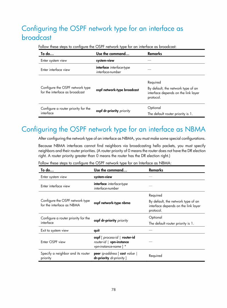
78
Configuring the OSPF network type for an interface as broadcast
Follow these steps to configure the OSPF network type for an interface as broadcast:
To do… Use the command… Remarks
Enter system view system-view —
Enter interface view interface interface-type interface-number
—
Configure the OSPF network type for the interface as broadcast
ospf network-type broadcast
Required
By default, the network type of an interface depends on the link layer protocol.
Configure a router priority for the interface
ospf dr-priority priority Optional
The default router priority is 1.
Configuring the OSPF network type for an interface as NBMA After configuring the network type of an interface as NBMA, you must make some special configurations.
Because NBMA interfaces cannot find neighbors via broadcasting hello packets, you must specify neighbors and their router priorities. (A router priority of 0 means the router does not have the DR election right. A router priority greater than 0 means the router has the DR election right.)
Follow these steps to configure the OSPF network type for an Interface as NBMA:
To do… Use the command… Remarks
Enter system view system-view —
Enter interface view interface interface-type interface-number
—
Configure the OSPF network type for the interface as NBMA ospf network-type nbma
Required
By default, the network type of an interface depends on the link layer protocol.
Configure a router priority for the interface ospf dr-priority priority
Optional
The default router priority is 1.
Exit to system view quit —
Enter OSPF view ospf [ process-id | router-id router-id | vpn-instance vpn-instance-name ] *
—
Specify a neighbor and its router priority
peer ip-address [ cost value | dr-priority dr-priority ] Required

79
NOTE:
The router priority configured with the ospf dr-priority command and the one configured with the peer command have the following differences.
• The former is for actual DR election.
• The latter is to indicate whether a neighbor has the election right or not. If you configure the router priority for a neighbor as 0, the local router will assume the neighbor has no election right, and send nohello packets to this neighbor. However, if the local router is the DR or BDR, it still sends hello packets tothe neighbor with priority 0 for adjacency establishment.
Configuring the OSPF network type for an interface as P2MP Follow these steps to configure the OSPF network type for an interface as P2MP:
To do… Use the command… Remarks
Enter system view system-view —
Enter interface view interface interface-type interface-number
—
Configure the OSPF network type for the interface as P2MP ospf network-type p2mp [ unicast ]
Required
By default, the network type of an interface depends on the link layer protocol.
After you configure the OSPF network type for an interface as P2MP unicast, all packets are unicast over the interface. The interface cannot broadcast hello packets to discover neighbors. In that case, you need to manually specify the neighbors.
Exit to system view quit —
Enter OSPF view ospf [ process-id | router-id router-id | vpn-instance vpn-instance-name ] *
—
Specify a neighbor and its router priority on a P2MP unicast network
peer ip-address [ cost value | dr-priority dr-priority ]
Required if the interface type is P2MP unicast
Configuring the OSPF network type for an interface as P2P Follow these steps to configure the OSPF network type for an interface as P2P:
To do… Use the command… Remarks
Enter system view system-view —
Enter interface view interface interface-type interface-number
—

80
To do… Use the command… Remarks
Configure the OSPF network type for the interface as P2P ospf network-type p2p
Required
By default, the network type of an interface depends on the link layer protocol.
Configuring OSPF route control This section describes how to control the advertisement and reception of OSPF routing information, as well as route redistribution from other protocols.
Configuration prerequisites Before configuring OSPF route control, complete the following tasks:
• Configure IP addresses for interfaces
• Configure OSPF basic functions
• Configure filters if routing information filtering is needed
Configuring OSPF route summarization Route summarization is when an ABR or ASBR summarizes routes with the same prefix into a single route and distributes it to other areas.
Route summarization reduces the traffic of routing information exchanged between areas and the sizes of routing tables on routers, improving route calculation speed on routers.
For example, there are three internal routes in an area: 19.1.1.0/24, 19.1.2.0/24, and 19.1.3.0/24. By configuring route summarization on the ABR, the three routes are summarized into the route 19.1.0.0/16 that is advertised to other areas.
Configuring route summarization on an ABR
If contiguous network segments are available in the area, you can summarize them into a single network segment. An ABR generates Type-3 LSAs on a per network segment basis for an attached non-backbone area.
The ABR in the area distributes only the summary LSA to reduce the scale of LSDBs on routers in other areas and the influence of topology changes.
Follow these steps to configure route summarization on an ABR:
To do… Use the command… Remarks
Enter system view system-view —
Enter OSPF view ospf [ process-id | router-id router-id | vpn-instance vpn-instance-name ] *
—
Enter OSPF area view area area-id —
Configure ABR route summarization
abr-summary ip-address { mask | mask-length } [ advertise | not-advertise ] [ cost cost ]
Required
Not configured by default.
The command is available on an ABR only.

81
Configuring route summarization when redistributing routes into OSPF on an ASBR
Without route summarization, an ASBR advertises each redistributed route in a separate ASE LSA. After a summary route is configured, the ASBR advertises only the summary route in an ASE LSA instead of more specific routes, which reduces the number of LSAs in the LSDB.
The ASBR summarizes redistributed Type-5 LSAs that fall into the specified address range. If the ASBR is in an NSSA area, it also summarizes Type-7 LSAs that fall into the specified address range. If the ASBR is also the ABR, it summarizes Type-5 LSAs translated from Type-7 LSAs.
Follow these steps to configure route summarization when redistributing routes into OSPF on an ASBR:
To do… Use the command… Remarks
Enter system view system-view —
Enter OSPF view ospf [ process-id | router-id router-id | vpn-instance vpn-instance-name ]*
—
Configure ASBR route summarization
asbr-summary ip-address { mask | mask-length } [ tag tag | not-advertise | cost cost ] *
Required
The command is available on an ASBR only.
Not configured by default.
Configuring OSPF inbound route filtering
NOTE:
For more information about IP prefix list and routing policy, see the chapter “Routing policy configuration.”
OSPF calculates routes by using LSAs. The calculated routes can be filtered and only permitted routes are installed into the OSPF routing table.
OSPF provides the following filtering methods:
• Filters routing information by destination address through ACLs and IP address prefixes
• Filters routing information by next hop through the filtering criteria configured with the gateway keyword
• Filters routing information by destination address through ACLs and IP address prefixes and by next hop through the filtering criteria configured with the gateway keyword
• Filters routing information by routing policy specified by the route-policy keyword
Follow these steps to configure inbound route filtering:
To do… Use the command… Remarks
Enter system view system-view —
Enter OSPF view ospf [ process-id | router-id router-id | vpn-instance vpn-instance-name ] *
—
Configure inbound route filtering
filter-policy { acl-number [ gateway ip-prefix-name ] | gateway ip-prefix-name | ip-prefix ip-prefix-name [ gateway ip-prefix-name ] | route-policy route-policy-name } import
Required
Not configured by default.

82
Configuring ABR Type-3 LSA filtering You can configure an ABR to filter Type-3 LSAs advertised to an area.
Follow these steps to configure Type-3 LSA filtering on an ABR:
To do… Use the command… Remarks
Enter system view system-view —
Enter OSPF view ospf [ process-id | router-id router-id | vpn-instance vpn-instance-name ] *
—
Enter area view area area-id —
Configure ABR Type-3 LSA filtering filter { acl-number | ip-prefix ip-prefix-name } { import | export }
Required
Not configured by default.
Configuring an OSPF cost for an interface You can configure an OSPF cost for an interface by using either of the following methods:
• Configure the cost value in interface view
• Configure a bandwidth reference value for the interface. OSPF computes the cost with this formula: Interface OSPF cost = Bandwidth reference value (100 Mbps) ÷ Interface bandwidth (Mbps). If the calculated cost is greater than 65535, the value of 65535 is used. If the calculated cost is less than 1, the value of 1 is used.
If the cost value is not configured for an interface, OSPF computes the interface cost automatically.
Follow these steps to configure an OSPF cost for an interface:
To do… Use the command… Remarks
Enter system view system-view —
Enter interface view interface interface-type interface-number
—
Configure an OSPF cost for the interface
ospf cost value
Optional
The default cost depends on the interface type: 1 for a VLAN interface; 0 for a loopback interface; computed according to the bandwidth for other interfaces.
Follow these steps to configure a bandwidth reference value:
To do… Use the command… Remarks
Enter system view system-view —
Enter OSPF view ospf [ process-id | router-id router-id | vpn-instance vpn-instance-name ] *
—
Configure a bandwidth reference value
bandwidth-reference value Optional
The value defaults to 100 Mbps.

83
Configuring the maximum number of OSPF routes Follow these steps to configure the maximum number of routes:
To do… Use the command… Remarks
Enter system view system-view —
Enter OSPF view ospf [ process-id | router-id router-id | vpn-instance vpn-instance-name ] *
—
Configure the maximum number of OSPF routes
maximum-routes { external | inter | intra } number
Optional
The number varies with devices.
Configuring the maximum number of load-balanced routes If several equal-cost routes to the same destination are available, you can configure them as load-balanced routes to improve link utilization.
Follow these steps to configure the maximum number of load-balanced routes:
To do… Use the command… Remarks
Enter system view system-view —
Enter OSPF view ospf [ process-id | router-id router-id | vpn-instance vpn-instance-name ] *
—
Configure the maximum number of load-balanced routes
maximum load-balancing maximum Optional
8 by default
Configuring OSPF preference A router can run multiple routing protocols, and each protocol is assigned a preference. When the routing protocols find routes to the same destination, the route found by the protocol with the highest preference is selected as the best route.
Follow these steps to configure OSPF preference:
To do… Use the command… Remarks
Enter system view system-view —
Enter OSPF view ospf [ process-id | router-id router-id | vpn-instance vpn-instance-name ] *
—
Configure a preference for OSPF
preference [ ase ] [ route-policy route-policy-name ] value
Optional
By default, the preference of OSPF internal routes is 10, and the preference of OSPF external routes is 150.

84
Configuring OSPF route redistribution Configure route redistribution into OSPF
On a router running OSPF and other routing protocols, you can configure OSPF to redistribute routes from other protocols such as RIP, IS-IS, BGP, static, and direct routes, and advertise them in Type-5 LSAs or Type-7 LSAs.
By filtering redistributed routes, OSPF translates only permitted routes into Type-5 LSAs or Type-7 LSAs for advertisement.
Follow these steps to configure OSPF route redistribution:
To do… Use the command… Remarks
Enter system view system-view —
Enter OSPF view ospf [ process-id | router-id router-id | vpn-instance vpn-instance-name ] *
—
Configure OSPF to redistribute routes from another protocol
import-route protocol [ process-id | all-processes | allow-ibgp ] [ cost cost | type type | tag tag | route-policy route-policy-name ] *
Required
Not configured by default.
Configure OSPF to filter redistributed routes before advertisement
filter-policy { acl-number | ip-prefix ip-prefix-name } export [ protocol [ process-id ] ]
Optional
Not configured by default.
NOTE:
Only active routes can be redistributed. Use the display ip routing-table protocol command to view routestate information.
Configure OSPF to redistribute a default route
Using the import-route command cannot redistribute a default external route. To do so, you must use the default-route-advertise command.
Follow these steps to configure OSPF to redistribute a default external route:
To do… Use the command… Remarks
Enter system view system-view —
Enter OSPF view ospf [ process-id | router-id router-id | vpn-instance vpn-instance-name ] *
—
Redistribute a default route
default-route-advertise [ [ [ always | permit-calculate-other ] | cost cost | route-policy route-policy-name | type type ] * | summary cost cost ]
Required
Not redistributed by default.
NOTE:
The default-route-advertise summary cost command is applicable only to VPN, and the default route is redistributed in a Type-3 LSA. The PE router advertises the default route to the CE router.

85
Configure the default parameters for redistributed routes
You can configure default parameters, such as the cost, upper limit, tag and type for redistributed routes. Tags indicate information related to protocols. For example, when redistributing BGP routes, OSPF uses tags to identify AS IDs.
Follow these steps to configure the default parameters for redistributed routes:
To do… Use the command… Remarks
Enter system view system-view —
Enter OSPF view ospf [ process-id | router-id router-id | vpn-instance vpn-instance-name ] *
—
Configure the default parameters for redistributed routes (cost, route number, tag, and type)
default { cost cost | limit limit | tag tag | type type } *
Optional
The default cost is 1, the default maximum number of routes redistributed per time is 1000, the default tag is 1, and default type of redistributed routes is Type-2.
Advertising a host route Follow these steps to advertise a host route:
To do… Use the command… Remarks
Enter system view system-view —
Enter OSPF view ospf [ process-id | router-id router-id | vpn-instance vpn-instance-name ] *
—
Enter area view area area-id —
Advertise a host route host-advertise ip-address cost Optional
Not advertised by default.
Tuning and optimizing OSPF networks You can optimize your OSPF network in the following ways:
• Change OSPF packet timers to adjust the OSPF network convergence speed and network load. On low-speed links, consider the delay time for sending LSAs.
• Change the SPF calculation interval to reduce resource consumption caused by frequent network changes.
• Configure OSPF authentication to improve security.
• Configure OSPF network management functions, such as binding OSPF MIB with a process, sending trap information, and collecting log information.

86
Configuration prerequisites Before configuring OSPF network optimization, complete the following tasks:
• Configure IP addresses for interfaces
• Configure OSPF basic functions
Configuring OSPF packet timers You can configure the following timers on OSPF interfaces as needed.
• Hello timer—Interval for sending hello packets. It must be identical on OSPF neighbors. The longer the interval, the lower the convergence speed, and the smaller the network load.
• Poll timer—Interval for sending hello packets to a neighbor that is down on the NBMA network.
• Dead timer—Interval within which if the interface receives no hello packet from the neighbor, it declares the neighbor is down.
• LSA retransmission timer—Interval within which if the interface receives no acknowledgement packets after sending an LSA to the neighbor, it retransmits the LSA.
Follow these steps to configure timers for OSPF packets:
To do… Use the command… Remarks
Enter system view system-view —
Enter interface view interface interface-type interface-number
—
Specify the hello interval ospf timer hello seconds
Optional
The hello interval defaults to 10 seconds on P2P and broadcast interfaces, and defaults to 30 seconds on P2MP and NBMA interfaces.
Specify the poll interval ospf timer poll seconds Optional
The poll interval defaults to 120 seconds.
Specify the dead interval
ospf timer dead seconds
Optional
The default dead interval is 40 seconds on P2P and broadcast interfaces and 120 seconds on P2MP and NBMA interfaces.
Specify the retransmission interval ospf timer retransmit interval
Optional
The retransmission interval defaults to 5 seconds.
NOTE:
• The hello and dead intervals restore to default values after you change the network type for an interface.
• The dead interval must be at least four times the hello interval on an interface.
• The poll interval is at least four times the hello interval.
• The retransmission interval must not be so small to avoid unnecessary LSA retransmissions. In general,this value is bigger than the round-trip time of a packet between two neighbors.

87
Specifying LSA transmission delay Each LSA in the LSDB has an age that is incremented by 1 every second, but the age does not change during transmission. It is necessary to add a transmission delay into the age time especially for low-speed links.
Follow these steps to specify the LSA transmission delay on an interface:
To do… Use the command… Remarks
Enter system view system-view —
Enter interface view interface interface-type interface-number
—
Specify the LSA transmission delay ospf trans-delay seconds Optional
1 second by default
Specifying SPF calculation interval LSDB changes lead to SPF calculations. When the topology changes frequently, a large amount of network and router resources are occupied by SPF calculation. Adjust the SPF calculation interval to reduce the impact.
Follow these steps to configure SPF calculation interval:
To do… Use the command… Remarks
Enter system view system-view —
Enter OSPF view ospf [ process-id | router-id router-id | vpn-instance vpn-instance-name ] *
—
Specify the SPF calculation interval
spf-schedule-interval maximum-interval [ minimum-interval [ incremental-interval ] ]
Optional
By default, the interval is 5 seconds.
NOTE:
When network changes are not frequent, the minimum-interval is adopted. If network changes become frequent, the SPF calculation interval is incremented by incremental-interval × 2n-2 (n is the number of calculation times) each time a calculation occurs until the maximum-interval is reached.
Specifying the LSA arrival interval After receiving the same LSA as the previously received LSA within the LSA arrival interval, OSPF discards the LSA.
Follow these steps to configure the LSA arrival interval:
To do… Use the command… Remarks
Enter system view system-view —
Enter OSPF view ospf [ process-id | router-id router-id | vpn-instance vpn-instance-name ] *
—

88
To do… Use the command… Remarks
Configure the LSA arrival interval lsa-arrival-interval interval Optional
1000 milliseconds by default
NOTE:
The interval set with the lsa-arrival-interval command must be smaller than or equal to the interval set withthe lsa-generation-interval command.
Specifying the LSA generation interval You can adjust the LSA generation interval to protect network resources and routers from being over consumed by frequent network changes.
Follow these steps to configure the LSA generation interval:
To do… Use the command… Remarks
Enter system view system-view —
Enter OSPF view ospf [ process-id | router-id router-id | vpn-instance vpn-instance-name ] * Required
Configure the LSA generation interval
lsa-generation-interval maximum-interval [ initial-interval [ incremental-interval ] ]
Optional
By default, the maximum interval is 5 seconds, the minimum interval is 0 milliseconds, and the incremental interval is 5000 milliseconds.
NOTE:
When network changes are not frequent, LSAs are generated at the minimum-interval. If network changesbecome frequent, the LSA generation interval is incremented by incremental-interval × 2n-2 (n is the number of generation times) each time a LSA generation occurs until the maximum-interval is reached.
Disabling interfaces from receiving and sending OSPF packets Follow these steps to disable interfaces from receiving and sending routing information:
To do… Use the command… Remarks
Enter system view system-view —
Enter OSPF view ospf [ process-id | router-id router-id | vpn-instance vpn-instance-name ] *
—
Disable interfaces from receiving and sending OSPF packets
silent-interface { interface-type interface-number | all }
Optional
Not disabled by default

89
NOTE:
• Different OSPF processes can disable the same interface from receiving and sending OSPF packets. Thesilent-interface command disables only the interfaces associated with the current process rather than interfaces associated with other processes.
• After an OSPF interface is set to silent, other interfaces on the router can advertise direct routes of the interface in Router LSAs, but the interface cannot send any packet. This configuration can enhance OSPF adaptability and reduce resource consumption.
Configuring stub routers A stub router is used for traffic control. It tells other OSPF routers to not use it to forward data.
The Router LSAs from the stub router may contain different link type values. A value of 3 means a link to a stub network, and the cost of the link will not be changed. A value of 1, 2, or 4 means a point-to-point link, a link to a transit network, or a virtual link. On such links, a maximum cost value of 65535 is used. Thus, neighbors find that the links to the stub router have large costs that they will not send packets to the stub router for forwarding as long as another route with a smaller cost exists.
Follow these steps to configure a router as a stub router:
To do… Use the command… Remarks
Enter system view system-view —
Enter OSPF view ospf [ process-id | router-id router-id | vpn-instance vpn-instance-name ] *
—
Configure the router as a stub router
stub-router Required
Not configured by default.
NOTE:
A stub router has nothing to do with a stub area.
Configuring OSPF authentication You can configure OSPF packet authentication to ensure the security of packet exchanges.
After authentication is configured, OSPF only receives packets that pass authentication. Failed packets cannot establish neighboring relationships.
To configure OSPF authentication, you must configure the same area authentication mode on all the routers in the area. In addition, the authentication mode and password for all interfaces attached to the same area must be identical.
Follow these steps to configure OSPF authentication:
To do… Use the command… Remarks
Enter system view system-view —
Enter OSPF view ospf [ process-id | router-id router-id | vpn-instance vpn-instance-name ] *
—
Enter area view area area-id —
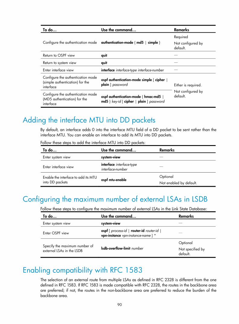
90
To do… Use the command… Remarks
Configure the authentication mode authentication-mode { md5 | simple } Required
Not configured by default.
Return to OSPF view quit —
Return to system view quit —
Enter interface view interface interface-type interface-number —
Configure the authentication mode (simple authentication) for the interface
ospf authentication-mode simple [ cipher | plain ] password Either is required.
Not configured by default. Configure the authentication mode
(MD5 authentication) for the interface
ospf authentication-mode { hmac-md5 | md5 } key-id [ cipher | plain ] password
Adding the interface MTU into DD packets By default, an interface adds 0 into the interface MTU field of a DD packet to be sent rather than the interface MTU. You can enable an interface to add its MTU into DD packets.
Follow these steps to add the interface MTU into DD packets:
To do… Use the command… Remarks
Enter system view system-view —
Enter interface view interface interface-type interface-number
—
Enable the interface to add its MTU into DD packets
ospf mtu-enable Optional
Not enabled by default.
Configuring the maximum number of external LSAs in LSDB Follow these steps to configure the maximum number of external LSAs in the Link State Database:
To do… Use the command… Remarks
Enter system view system-view —
Enter OSPF view ospf [ process-id | router-id router-id | vpn-instance vpn-instance-name ] *
—
Specify the maximum number of external LSAs in the LSDB
lsdb-overflow-limit number Optional
Not specified by default.
Enabling compatibility with RFC 1583 The selection of an external route from multiple LSAs as defined in RFC 2328 is different from the one defined in RFC 1583. If RFC 1583 is made compatible with RFC 2328, the routes in the backbone area are preferred; if not, the routes in the non-backbone area are preferred to reduce the burden of the backbone area.

91
Follow these steps to make them compatible:
To do… Use the command… Remarks
Enter system view system-view —
Enter OSPF view ospf [ process-id | router-id router-id | vpn-instance vpn-instance-name ] * Required
Enable compatibility with RFC 1583
rfc1583 compatible Optional
Enabled by default
NOTE:
To avoid routing loops, HP recommends configuring all the routers to be either compatible or incompatiblewith RFC 1583.
Logging neighbor state changes Follow these steps to enable the logging of neighbor state changes:
To do… Use the command… Remarks
Enter system view system-view —
Enter OSPF view ospf [ process-id | router-id router-id | vpn-instance vpn-instance-name ] *
—
Enable the logging of neighbor state changes log-peer-change
Optional
Enabled by default
Configuring OSPF network management With trap generation enabled, OSPF generates traps to report important events. Traps fall into the following levels.
• Level-3—fault traps
• Level-4—alarm traps
• Level-5—normal but important traps
• Level-6—notification traps
The generated traps are sent to the information center of the device. The output rules of the traps such as whether to output the traps and the output direction are determined according to the information center configuration. (For information center configuration, see Network Management and Monitoring Configuration Guide.)
Follow these steps to configure OSPF network management:
To do… Use the command… Remarks
Enter system view system-view —
Bind OSPF MIB to an OSPF process
ospf mib-binding process-id
Optional
The OSPF process with the smallest process-id is bound with OSPF MIB by default.

92
To do… Use the command… Remarks
Enable OSPF trap generation
snmp-agent trap enable ospf [ process-id ] [ ifauthfail | ifcfgerror | ifrxbadpkt | ifstatechange | iftxretransmit | lsdbapproachoverflow | lsdboverflow | maxagelsa | nbrstatechange | originatelsa | vifcfgerror | virifauthfail | virifrxbadpkt | virifstatechange | viriftxretransmit | virnbrstatechange ] *
Optional
Enabled by default
Enabling message logging Follow these steps to enable message logging:
To do… Use the command… Remarks
Enter system view system-view —
Enter OSPF view ospf [ process-id | router-id router-id | vpn-instance vpn-instance-name ] *
—
Enable message logging enable log [ config | error | state ] Required
Not enabled by default.
Enabling the advertisement and reception of opaque LSAs With this feature enabled, OSPF can receive and advertise Type 9, Type 10, and Type 11 opaque LSAs.
Follow these steps to enable the advertisement and reception of opaque LSAs:
To do… Use the command… Remarks
Enter system view system-view —
Enter OSPF view ospf [ process-id | router-id router-id | vpn-instance vpn-instance-name ] *
—
Enable the advertisement and reception of opaque LSAs
opaque-capability enable Optional
Disabled by default
Configuring OSPF to give priority to receiving and processing hello packets
To ensure OSPF runs properly, a router receives and processes hello packets and other protocol packets at the same time. When the router has established neighbor relationships with multiple routers, and the routing table size is big, the router must receive and process large numbers of packets. In this case, you can configure OSPF to give priority to receiving and processing hello packets to ensure stable neighbor relationships.
Follow these steps to configure OSPF to give priority to receiving and processing hello packets:
To do… Use the command… Remarks
Enter system view system-view —

93
To do… Use the command… Remarks
Configure OSPF to give priority to receiving and processing hello packets
ospf packet-process prioritized-treatment Required
Not configured by default.
Configuring the LSU transmit rate Sending large numbers of LSU packets affects router performance and consumes too much network bandwidth. You can configure the router to send LSU packets at a proper interval and limit the maximum number of LSU packets sent out of an OSPF interface each time.
Follow these steps to configure the LSU transmit rate:
To do… Use the command… Remarks
Enter system view system-view —
Enter OSPF view ospf [ process-id | router-id router-id | vpn-instance vpn-instance-name ] *
—
Configure the LSU transmit rate transmit-pacing interval interval count count
Optional
By default, an OSPF interface sends up to three LSU packets every 20 milliseconds.
Enabling OSPF ISPF When a network topology is changed, Incremental Shortest Path First (ISPF) allows the system to recomputes only the affected part of the shortest path tree (SPT), instead of the entire SPT.
Follow these steps to enable OSPF ISPF:
To do… Use the command… Remarks
Enter system view system-view —
Enter OSPF view ospf [ process-id | router-id router-id | vpn-instance vpn-instance-name ] *
—
Enable OSPF ISPF ispf enable Optional
Disabled by default.
Configuring OSPF FRR
NOTE:
• Do not use FRR and BFD at the same time. Otherwise, FRR may fail to take effect.
• Do not use the fast-reroute auto command together with the commands vlink-peer.
Introduction
When a link fails, the packets on the link are discarded, and a routing loop may occur until OSPF completes routing convergence based on the new network topology.
You can enable OSPF fast reroute (FRR) to solve this problem.

94
Figure 37 Network diagram for OSPF FRR
In Figure 37, after you enable FRR on Router B, OSPF automatically calculates or designates a backup next hop when a link failure is detected. Packets are directed to the backup next hop. At the same time, OSPF calculates the shortest path based on the new network topology, and forwards packets over the path after routing convergence.
You can either configure OSPF FRR to calculate a backup next hop automatically, or to designate a backup next hop by using a routing policy.
Configuration prerequisites
Before configuring OSPF FRR, complete the following tasks:
• Configure network layer addresses for interfaces
• Enable OSPF
Configure OSPF FRR to automatically calculate a backup next hop
Follow these steps to configure automatic OSPF FRR:
To do… Use the command… Remarks
Enter system view system-view —
Configure the source address of echo packets bfd echo-source-ip ip-address
Required
Not configured by default.
Enter OSPF view ospf [ process-id | router-id router-id | vpn-instance vpn-instance-name ] *
—
Enable OSPF FRR to automatically calculate a backup next hop
fast-reroute auto [ abr-only ]
Required
Not configured by default.
If abr-only is specified, the route to the ABR is selected as the backup path.
Configure OSPF FRR to designate a backup next hop with a routing policy
Before configuring this task, you need to use the apply fast-reroute backup-interface command to specify a backup next hop in the routing policy to be referenced. For more information about the apply fast-reroute backup-interface command and routing policy configuration, see the chapter “Routing policy configuration.”
Follow these steps to configure OSPF FRR:
To do… Use the command… Remarks
Enter system view system-view —
Configure the source address of echo packets bfd echo-source-ip ip-address
Required
Not configured by default.

95
To do… Use the command… Remarks
Enter OSPF view ospf [ process-id | router-id router-id | vpn-instance vpn-instance-name ] *
—
Enable OSPF FRR to designate a backup next hop by using a routing policy
fast-reroute route-policy route-policy-name
Required
Not configured by default.
Configuring OSPF Graceful Restart
OSPF GR involves the following:
• IETF standard GR: Uses Opaque LSAs to implement GR
• Non IETF standard GR: Uses link local signaling (LLS) to advertise GR capability and uses out of band synchronization to synchronize the LSDB
A device can act as a GR Restarter and GR Helper at the same time.
Configuring the OSPF GR Restarter You can configure the IETF standard or non IETF standard OSPF GR Restarter.
Configure the IETF standard OSPF GR Restarter
Follow these steps to configure the standard IETF OSPF GR Restarter:
To do… Use the command… Remarks
Enter system view system-view —
Enable OSPF and enter its view ospf [ process-id | router-id router-id | vpn-instance vpn-instance-name ] *
—
Enable opaque LSA advertisement capability opaque-capability enable
Required
Disabled by default
Enable the IETF standard Graceful Restart capability
graceful-restart ietf Required
Disabled by default
Configure the Graceful Restart interval graceful-restart interval timer
Optional
120 seconds by default
Configure the non-IETF standard OSPF GR Restarter
Follow these steps to configure non-IETF standard OSPF GR Restarter:
To do… Use the command… Remarks
Enter system view system-view —
Enable OSPF and enter its view ospf [ process-id | router-id router-id | vpn-instance vpn-instance-name ] *
—

96
To do… Use the command… Remarks
Enable the link-local signaling capability
enable link-local-signaling Required
Disabled by default
Enable the out-of-band re-synchronization capability
enable out-of-band-resynchronization
Required
Disabled by default
Enable non-IETF standard Graceful Restart capability for OSPF
graceful-restart [ nonstandard ] Required
Disabled by default
Configure Graceful Restart interval for OSPF graceful-restart interval timer
Optional
120 seconds by default
Configuring the OSPF GR Helper You can configure the IETF standard or non-IETF standard OSPF GR Helper.
Configuring the IETF standard OSPF GR Helper
Follow these steps to configure the IETF standard OSPF GR Helper:
To do… Use the command… Remarks
Enter system view system-view —
Enable OSPF and enter its view ospf [ process-id | router-id router-id | vpn-instance vpn-instance-name ] *
—
Enable opaque LSA reception and advertisement
opaque-capability enable Required
Not enabled by default.
Configure the neighbors for which the router can serve as a GR Helper
graceful-restart help { acl-number | prefix prefix-list }
Optional
The router can serve as a GR Helper for any OSPF neighbor by default.
Configuring the non IETF standard OSPF GR Helper
Follow these steps to configure the non IETF standard OSPF GR Helper:
To do… Use the command… Remarks
Enter system view system-view —
Enable OSPF and enter its view ospf [ process-id | router-id router-id | vpn-instance vpn-instance-name ] *
—
Enable the link-local signaling capability enable link-local-signaling
Required
Disabled by default
Enable the out-of-band re-synchronization capability
enable out-of-band-resynchronization
Required
Disabled by default

97
To do… Use the command… Remarks
Configure the neighbors for which the router can serve as a GR Helper
graceful-restart help { acl-number | prefix prefix-list }
Optional
The router can serve as a GR Helper for any OSPF neighbor by default.
Triggering OSPF Graceful Restart Performing a Master/Slave switchover, or performing the following configuration on an OSPF router, will trigger OSPF Graceful Restart.
Follow these steps to trigger OSPF Graceful Restart:
To do… Use the command… Remarks
Trigger OSPF Graceful Restart reset ospf [ process-id ] process graceful-restart
Required
Available in user view
Configuring BFD for OSPF OSPF supports the following BFD detection methods:
• Control packet bidirectional detection, which requires BFD configuration to be made on both OSPF routers on the link.
• Echo packet single-hop detection, which requires BFD configuration to be made on one OSPF router on the link.
Configuring control packet bidirectional detection Follow these steps to enable BFD control packet bidirectional detection on an OSPF interface:
To do… Use the command… Description
Enter system view system-view —
Enter interface view interface interface-type interface-number —
Enable BFD control packet bidirectional detection on the interface ospf bfd enable
Required
Not enabled by default
NOTE:
• One network segment can only belong to one area.
• Both ends of a BFD session must be on the same network segment and in the same area.
Configuring echo packet single-hop detection Follow these steps to enable BFD echo packet single-hop detection on an OSPF interface:

98
To do… Use the command… Description
Enter system view system-view —
Configure the source address of echo packets bfd echo-source-ip ip-address Required
Not configured by default
Enter interface view interface interface-type interface-number
—
Enable BFD echo packet single-hop detection on the interface ospf bfd enable echo
Required
Not enabled by default
Displaying and maintaining OSPF To do… Use the command… Remarks
Display OSPF brief information display ospf [ process-id ] brief [ | { begin | exclude | include } regular-expression ]
Available in any view
Display OSPF statistics display ospf [ process-id ] cumulative [ | { begin | exclude | include } regular-expression ]
Display Link State Database information
display ospf [ process-id ] lsdb [ brief | [ { ase | router | network | summary | asbr | nssa | opaque-link | opaque-area | opaque-as } [ link-state-id ] ] [ originate-router advertising-router-id | self-originate ] ] [ | { begin | exclude | include } regular-expression ]
Display OSPF neighbor information
display ospf [ process-id ] peer [ verbose ] [ interface-type interface-number ] [ neighbor-id ] [ | { begin | exclude | include } regular-expression ]
Display neighbor statistics of OSPF areas
display ospf [ process-id ] peer statistics [ | { begin | exclude | include } regular-expression ]
Display next hop information display ospf [ process-id ] nexthop [ | { begin | exclude | include } regular-expression ]
Display routing table information
display ospf [ process-id ] routing [ interface interface-type interface-number ] [ nexthop nexthop-address ] [ | { begin | exclude | include } regular-expression ]
Display virtual link information display ospf [ process-id ] vlink [ | { begin | exclude | include } regular-expression ]
Display OSPF request queue information
display ospf [ process-id ] request-queue [ interface-type interface-number ] [ neighbor-id ] [ | { begin | exclude | include } regular-expression ]
Display OSPF retransmission queue information
display ospf [ process-id ] retrans-queue [ interface-type interface-number ] [ neighbor-id ] [ | { begin | exclude | include } regular-expression ]
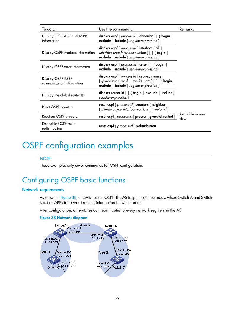
99
To do… Use the command… Remarks
Display OSPF ABR and ASBR information
display ospf [ process-id ] abr-asbr [ | { begin | exclude | include } regular-expression ]
Display OSPF interface information display ospf [ process-id ] interface [ all | interface-type interface-number ] [ | { begin | exclude | include } regular-expression ]
Display OSPF error information display ospf [ process-id ] error [ | { begin | exclude | include } regular-expression ]
Display OSPF ASBR summarization information
display ospf [ process-id ] asbr-summary [ ip-address { mask | mask-length } ] [ | { begin | exclude | include } regular-expression ]
Display the global router ID display router id [ | { begin | exclude | include } regular-expression ]
Reset OSPF counters reset ospf [ process-id ] counters [ neighbor [ interface-type interface-number ] [ router-id ] ]
Available in user view Reset an OSPF process reset ospf [ process-id ] process [ graceful-restart ]
Re-enable OSPF route redistribution reset ospf [ process-id ] redistribution
OSPF configuration examples
NOTE:
These examples only cover commands for OSPF configuration.
Configuring OSPF basic functions Network requirements
As shown in Figure 38, all switches run OSPF. The AS is split into three areas, where Switch A and Switch B act as ABRs to forward routing information between areas.
After configuration, all switches can learn routes to every network segment in the AS.
Figure 38 Network diagram

100
Configuration procedure
1. Configure IP addresses for interfaces. (Details not shown)
2. Configure OSPF basic functions.
# Configure Switch A. <SwitchA> system-view
[SwitchA] ospf
[SwitchA-ospf-1] area 0
[SwitchA-ospf-1-area-0.0.0.0] network 10.1.1.0 0.0.0.255
[SwitchA-ospf-1-area-0.0.0.0] quit
[SwitchA-ospf-1] area 1
[SwitchA-ospf-1-area-0.0.0.1] network 10.2.1.0 0.0.0.255
[SwitchA-ospf-1-area-0.0.0.1] quit
[SwitchA-ospf-1] quit
# Configure Switch B. <SwitchB> system-view
[SwitchB] ospf
[SwitchB-ospf-1] area 0
[SwitchB-ospf-1-area-0.0.0.0] network 10.1.1.0 0.0.0.255
[SwitchB-ospf-1-area-0.0.0.0] quit
[SwitchB-ospf-1] area 2
[SwitchB-ospf-1-area-0.0.0.2] network 10.3.1.0 0.0.0.255
[SwitchB-ospf-1-area-0.0.0.2] quit
[SwitchB-ospf-1] quit
# Configure Switch C <SwitchC> system-view
[SwitchC] ospf
[SwitchC-ospf-1] area 1
[SwitchC-ospf-1-area-0.0.0.1] network 10.2.1.0 0.0.0.255
[SwitchC-ospf-1-area-0.0.0.1] network 10.4.1.0 0.0.0.255
[SwitchC-ospf-1-area-0.0.0.1] quit
[SwitchC-ospf-1] quit
# Configure Switch D <SwitchD> system-view
[SwitchD] ospf
[SwitchD-ospf-1] area 2
[SwitchD-ospf-1-area-0.0.0.2] network 10.3.1.0 0.0.0.255
[SwitchD-ospf-1-area-0.0.0.2] network 10.5.1.0 0.0.0.255
[SwitchD-ospf-1-area-0.0.0.2] quit
[SwitchD-ospf-1] quit
3. Verify the configuration.
# Display information about neighbors on Switch A. [SwitchA] display ospf peer verbose
OSPF Process 1 with Router ID 10.2.1.1
Neighbors
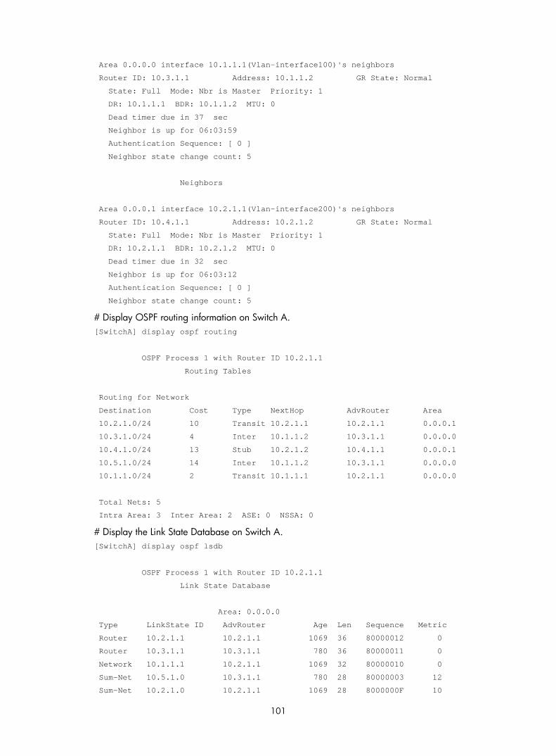
101
Area 0.0.0.0 interface 10.1.1.1(Vlan-interface100)'s neighbors
Router ID: 10.3.1.1 Address: 10.1.1.2 GR State: Normal
State: Full Mode: Nbr is Master Priority: 1
DR: 10.1.1.1 BDR: 10.1.1.2 MTU: 0
Dead timer due in 37 sec
Neighbor is up for 06:03:59
Authentication Sequence: [ 0 ]
Neighbor state change count: 5
Neighbors
Area 0.0.0.1 interface 10.2.1.1(Vlan-interface200)'s neighbors
Router ID: 10.4.1.1 Address: 10.2.1.2 GR State: Normal
State: Full Mode: Nbr is Master Priority: 1
DR: 10.2.1.1 BDR: 10.2.1.2 MTU: 0
Dead timer due in 32 sec
Neighbor is up for 06:03:12
Authentication Sequence: [ 0 ]
Neighbor state change count: 5
# Display OSPF routing information on Switch A. [SwitchA] display ospf routing
OSPF Process 1 with Router ID 10.2.1.1
Routing Tables
Routing for Network
Destination Cost Type NextHop AdvRouter Area
10.2.1.0/24 10 Transit 10.2.1.1 10.2.1.1 0.0.0.1
10.3.1.0/24 4 Inter 10.1.1.2 10.3.1.1 0.0.0.0
10.4.1.0/24 13 Stub 10.2.1.2 10.4.1.1 0.0.0.1
10.5.1.0/24 14 Inter 10.1.1.2 10.3.1.1 0.0.0.0
10.1.1.0/24 2 Transit 10.1.1.1 10.2.1.1 0.0.0.0
Total Nets: 5
Intra Area: 3 Inter Area: 2 ASE: 0 NSSA: 0
# Display the Link State Database on Switch A. [SwitchA] display ospf lsdb
OSPF Process 1 with Router ID 10.2.1.1
Link State Database
Area: 0.0.0.0
Type LinkState ID AdvRouter Age Len Sequence Metric
Router 10.2.1.1 10.2.1.1 1069 36 80000012 0
Router 10.3.1.1 10.3.1.1 780 36 80000011 0
Network 10.1.1.1 10.2.1.1 1069 32 80000010 0
Sum-Net 10.5.1.0 10.3.1.1 780 28 80000003 12
Sum-Net 10.2.1.0 10.2.1.1 1069 28 8000000F 10

102
Sum-Net 10.3.1.0 10.3.1.1 780 28 80000014 2
Sum-Net 10.4.1.0 10.2.1.1 769 28 8000000F 13
Area: 0.0.0.1
Type LinkState ID AdvRouter Age Len Sequence Metric
Router 10.2.1.1 10.2.1.1 769 36 80000012 0
Router 10.4.1.1 10.4.1.1 1663 48 80000012 0
Network 10.2.1.1 10.2.1.1 769 32 80000010 0
Sum-Net 10.5.1.0 10.2.1.1 769 28 80000003 14
Sum-Net 10.3.1.0 10.2.1.1 1069 28 8000000F 4
Sum-Net 10.1.1.0 10.2.1.1 1069 28 8000000F 2
Sum-Asbr 10.3.1.1 10.2.1.1 1069 28 8000000F 2
# Display OSPF routing information on Switch D. [SwitchD] display ospf routing
OSPF Process 1 with Router ID 10.5.1.1
Routing Tables
Routing for Network
Destination Cost Type NextHop AdvRouter Area
10.2.1.0/24 22 Inter 10.3.1.1 10.3.1.1 0.0.0.2
10.3.1.0/24 10 Transit 10.3.1.2 10.3.1.1 0.0.0.2
10.4.1.0/24 25 Inter 10.3.1.1 10.3.1.1 0.0.0.2
10.5.1.0/24 10 Stub 10.5.1.1 10.5.1.1 0.0.0.2
10.1.1.0/24 12 Inter 10.3.1.1 10.3.1.1 0.0.0.2
Total Nets: 5
Intra Area: 2 Inter Area: 3 ASE: 0 NSSA: 0
# On Switch D, ping the IP address 10.4.1.1 to check connectivity. [SwitchD] ping 10.4.1.1
PING 10.4.1.1: 56 data bytes, press CTRL_C to break
Reply from 10.4.1.1: bytes=56 Sequence=2 ttl=253 time=2 ms
Reply from 10.4.1.1: bytes=56 Sequence=2 ttl=253 time=1 ms
Reply from 10.4.1.1: bytes=56 Sequence=3 ttl=253 time=1 ms
Reply from 10.4.1.1: bytes=56 Sequence=4 ttl=253 time=1 ms
Reply from 10.4.1.1: bytes=56 Sequence=5 ttl=253 time=1 ms
--- 10.4.1.1 ping statistics ---
5 packet(s) transmitted
5 packet(s) received
0.00% packet loss
round-trip min/avg/max = 1/1/2 ms

103
Configuring OSPF route redistribution Network requirements
As shown in Figure 39, all the switches run OSPF, and the AS is divided into three areas. Switch A and Switch B act as ABRs to forward routes between areas. Switch C is configured as an ASBR to redistribute external routes (static routes). Routing information is propagated properly in the AS.
Figure 39 Network diagram
Configuration procedure
1. Configure IP addresses for interfaces. (Details not shown)
2. Configure OSPF basic functions. (See “Configuring OSPF basic functions”)
3. Configure OSPF to redistribute routes.
# On Switch C, configure a static route destined for network 3.1.2.0/24. <SwitchC> system-view
[SwitchC] ip route-static 3.1.2.1 24 10.4.1.2
# On Switch C, configure OSPF to redistribute static routes. [SwitchC] ospf 1
[SwitchC-ospf-1] import-route static
4. Verify the configuration.
# Display the ABR/ASBR information of Switch D. <SwitchD> display ospf abr-asbr
OSPF Process 1 with Router ID 10.5.1.1
Routing Table to ABR and ASBR
Type Destination Area Cost Nexthop RtType
Intra 10.3.1.1 0.0.0.2 10 10.3.1.1 ABR
Inter 10.4.1.1 0.0.0.2 22 10.3.1.1 ASBR
# Display the OSPF routing table of Switch D. <SwitchD> display ospf routing
OSPF Process 1 with Router ID 10.5.1.1
Routing Tables

104
Routing for Network
Destination Cost Type NextHop AdvRouter Area
10.2.1.0/24 22 Inter 10.3.1.1 10.3.1.1 0.0.0.2
10.3.1.0/24 10 Transit 10.3.1.2 10.3.1.1 0.0.0.2
10.4.1.0/24 25 Inter 10.3.1.1 10.3.1.1 0.0.0.2
10.5.1.0/24 10 Stub 10.5.1.1 10.5.1.1 0.0.0.2
10.1.1.0/24 12 Inter 10.3.1.1 10.3.1.1 0.0.0.2
Routing for ASEs
Destination Cost Type Tag NextHop AdvRouter
3.1.2.0/24 1 Type2 1 10.3.1.1 10.4.1.1
Total Nets: 6
Intra Area: 2 Inter Area: 3 ASE: 1 NSSA: 0
Configuring OSPF to advertise a summary route Network requirements
As shown in Figure 40:
• Switch A and Switch B are in AS 200, which runs OSPF.
• Switch C, Switch D, and Switch E are in AS 100, which runs OSPF.
An eBGP connection is established between Switch B and Switch C. Switch B and Switch C are configured to redistribute OSPF routes and direct routes into BGP and BGP routes into OSPF.
Switch B is configured with route summarization and advertises only the summary route 10.0.0.0/8 to reduce Switch A's routing table size.
Figure 40 Network diagram
Configuration procedure
1. Configure IP addresses for interfaces. (Details not shown)

105
2. Configure OSPF basic functions.
# Configure Switch A. <SwitchA> system-view
[SwitchA] ospf
[SwitchA-ospf-1] area 0
[SwitchA-ospf-1-area-0.0.0.0] network 11.2.1.0 0.0.0.255
[SwitchA-ospf-1-area-0.0.0.0] quit
[SwitchA-ospf-1] quit
# Configure Switch B. <SwitchB> system-view
[SwitchB] ospf
[SwitchB-ospf-1] area 0
[SwitchB-ospf-1-area-0.0.0.0] network 11.2.1.0 0.0.0.255
[SwitchB-ospf-1-area-0.0.0.0] quit
[SwitchB-ospf-1] quit
# Configure Switch C. <SwitchC> system-view
[SwitchC] ospf
[SwitchC-ospf-1] area 0
[SwitchC-ospf-1-area-0.0.0.0] network 10.1.1.0 0.0.0.255
[SwitchC-ospf-1-area-0.0.0.0] network 10.2.1.0 0.0.0.255
[SwitchC-ospf-1-area-0.0.0.0] quit
[SwitchC-ospf-1] quit
# Configure Switch D. <SwitchD> system-view
[SwitchD] ospf
[SwitchD-ospf-1] area 0
[SwitchD-ospf-1-area-0.0.0.0] network 10.1.1.0 0.0.0.255
[SwitchD-ospf-1-area-0.0.0.0] network 10.3.1.0 0.0.0.255
[SwitchD-ospf-1-area-0.0.0.0] quit
# Configure Switch E. <SwitchE> system-view
[SwitchE] ospf
[SwitchE-ospf-1] area 0
[SwitchE-ospf-1-area-0.0.0.0] network 10.2.1.0 0.0.0.255
[SwitchE-ospf-1-area-0.0.0.0] network 10.4.1.0 0.0.0.255
[SwitchE-ospf-1-area-0.0.0.0] quit
[SwitchE-ospf-1] quit
3. Configure BGP to redistribute OSPF routes and direct routes.
# Configure Switch B. [SwitchB] bgp 200
[SwitchB-bgp] peer 11.1.1.2 as 100
[SwitchB-bgp] import-route ospf
[SwitchB-bgp] import-route direct
[SwitchB-bgp] quit
# Configure Switch C.

106
[SwitchC] bgp 100
[SwitchC-bgp] peer 11.1.1.1 as 200
[SwitchC-bgp] import-route ospf
[SwitchC-bgp] import-route direct
[SwitchC-bgp] quit
4. Configure Switch B and Switch C to redistribute BGP routes into OSPF.
# Configure OSPF to redistribute routes from BGP on Switch B. [SwitchB] ospf
[SwitchB-ospf-1] import-route bgp
# Configure OSPF to redistribute routes from BGP on Switch C. [SwitchC] ospf
[SwitchC-ospf-1] import-route bgp
# Display the OSPF routing table of Switch A. [SwitchA] display ip routing-table
Routing Tables: Public
Destinations : 8 Routes : 8
Destination/Mask Proto Pre Cost NextHop Interface
10.1.1.0/24 O_ASE 150 1 11.2.1.1 Vlan100
10.2.1.0/24 O_ASE 150 1 11.2.1.1 Vlan100
10.3.1.0/24 O_ASE 150 1 11.2.1.1 Vlan100
10.4.1.0/24 O_ASE 150 1 11.2.1.1 Vlan100
11.2.1.0/24 Direct 0 0 11.2.1.2 Vlan100
11.2.1.2/32 Direct 0 0 127.0.0.1 InLoop0
127.0.0.0/8 Direct 0 0 127.0.0.1 InLoop0
127.0.0.1/32 Direct 0 0 127.0.0.1 InLoop0
5. Configure summary route 10.0.0.0/8 on Switch B and advertise it. [SwitchB-ospf-1] asbr-summary 10.0.0.0 8
# Display the OSPF routing table of Switch A. [SwitchA] display ip routing-table
Routing Tables: Public
Destinations : 5 Routes : 5
Destination/Mask Proto Pre Cost NextHop Interface
10.0.0.0/8 O_ASE 150 2 11.2.1.1 Vlan100
11.2.1.0/24 Direct 0 0 11.2.1.2 Vlan100
11.2.1.2/32 Direct 0 0 127.0.0.1 InLoop0
127.0.0.0/8 Direct 0 0 127.0.0.1 InLoop0
127.0.0.1/32 Direct 0 0 127.0.0.1 InLoop0
The output shows that routes 10.1.1.0/24, 10.2.1.0/24, 10.3.1.0/24 and 10.4.1.0/24 are summarized into one route 10.0.0.0/8.

107
Configuring an OSPF stub area Network requirements
Figure 41 shows an AS is split into three areas, where all switches run OSPF. Switch A and Switch B act as ABRs to forward routing information between areas. Switch D acts as the ASBR to redistribute routes (static routes).
Configure Area 1 as a stub area, reducing LSAs to this area without affecting route reachability.
Figure 41 Network diagram
Configuration procedure
1. Configure IP addresses for interfaces. (Details not shown)
2. Configure OSPF basic functions. (See “Configuring OSPF basic functions”)
3. Configure Switch D to redistribute static routes. <SwitchD> system-view
[SwitchD] ip route-static 3.1.2.1 24 10.5.1.2
[SwitchD] ospf
[SwitchD-ospf-1] import-route static
[SwitchD-ospf-1] quit
# Display ABR/ASBR information on Switch C. <SwitchC> display ospf abr-asbr
OSPF Process 1 with Router ID 10.4.1.1
Routing Table to ABR and ASBR
Type Destination Area Cost Nexthop RtType
Intra 10.2.1.1 0.0.0.1 3 10.2.1.1 ABR
Inter 10.3.1.1 0.0.0.1 5 10.2.1.1 ABR
Inter 10.5.1.1 0.0.0.1 7 10.2.1.1 ASBR
# Display OSPF routing table information on Switch C. <SwitchC> display ospf routing
OSPF Process 1 with Router ID 10.4.1.1

108
Routing Tables
Routing for Network
Destination Cost Type NextHop AdvRouter Area
10.2.1.0/24 3 Transit 10.2.1.2 10.2.1.1 0.0.0.1
10.3.1.0/24 7 Inter 10.2.1.1 10.2.1.1 0.0.0.1
10.4.1.0/24 3 Stub 10.4.1.1 10.4.1.1 0.0.0.1
10.5.1.0/24 17 Inter 10.2.1.1 10.2.1.1 0.0.0.1
10.1.1.0/24 5 Inter 10.2.1.1 10.2.1.1 0.0.0.1
Routing for ASEs
Destination Cost Type Tag NextHop AdvRouter
3.1.2.0/24 1 Type2 1 10.2.1.1 10.5.1.1
Total Nets: 6
Intra Area: 2 Inter Area: 3 ASE: 1 NSSA: 0
NOTE:
In the above output, because Switch C resides in a normal OSPF area, its routing table contains an external route.
4. Configure Area 1 as a Stub area.
# Configure Switch A. <SwitchA> system-view
[SwitchA] ospf
[SwitchA-ospf-1] area 1
[SwitchA-ospf-1-area-0.0.0.1] stub
[SwitchA-ospf-1-area-0.0.0.1] quit
[SwitchA-ospf-1] quit
# Configure Switch C. <SwitchC> system-view
[SwitchC] ospf
[SwitchC-ospf-1] area 1
[SwitchC-ospf-1-area-0.0.0.1] stub
[SwitchC-ospf-1-area-0.0.0.1] quit
[SwitchC-ospf-1] quit
# Display OSPF routing information on Switch C [SwitchC] display ospf routing
OSPF Process 1 with Router ID 10.4.1.1
Routing Tables
Routing for Network
Destination Cost Type NextHop AdvRouter Area
0.0.0.0/0 4 Inter 10.2.1.1 10.2.1.1 0.0.0.1
10.2.1.0/24 3 Transit 10.2.1.2 10.2.1.1 0.0.0.1
10.3.1.0/24 7 Inter 10.2.1.1 10.2.1.1 0.0.0.1

109
10.4.1.0/24 3 Stub 10.4.1.1 10.4.1.1 0.0.0.1
10.5.1.0/24 17 Inter 10.2.1.1 10.2.1.1 0.0.0.1
10.1.1.0/24 5 Inter 10.2.1.1 10.2.1.1 0.0.0.1
Total Nets: 6
Intra Area: 2 Inter Area: 4 ASE: 0 NSSA: 0
NOTE:
When Switch C resides in the stub area, a default route takes the place of the external route.
# Filter Type-3 LSAs out the stub area [SwitchA] ospf
[SwitchA-ospf-1] area 1
[SwitchA-ospf-1-area-0.0.0.1] stub no-summary
[SwitchA-ospf-1-area-0.0.0.1] quit
# Display OSPF routing information on Switch C. [SwitchC] display ospf routing
OSPF Process 1 with Router ID 10.4.1.1
Routing Tables
Routing for Network
Destination Cost Type NextHop AdvRouter Area
0.0.0.0/0 4 Inter 10.2.1.1 10.2.1.1 0.0.0.1
10.2.1.0/24 3 Transit 10.2.1.2 10.4.1.1 0.0.0.1
10.4.1.0/24 3 Stub 10.4.1.1 10.4.1.1 0.0.0.1
Total Nets: 3
Intra Area: 2 Inter Area: 1 ASE: 0 NSSA: 0
NOTE:
After this configuration, routing entries on the stub router are further reduced, containing only one defaultexternal route.
Configuring an OSPF NSSA area Network requirements
Figure 42 shows an AS is split into three areas, where all switches run OSPF. Switch A and Switch B act as ABRs to forward routing information between areas.
Configure Area 1 as an NSSA area and configure Switch C as the ASBR to redistribute static routes into the AS.

110
Figure 42 Network diagram
Configuration procedure
1. Configure IP addresses for interfaces.
2. Configure OSPF basic functions. (See “Configuring OSPF basic functions”)
3. Configure Area 1 as an NSSA area.
# Configure Switch A. <SwitchA> system-view
[SwitchA] ospf
[SwitchA-ospf-1] area 1
[SwitchA-ospf-1-area-0.0.0.1] nssa default-route-advertise no-summary
[SwitchA-ospf-1-area-0.0.0.1] quit
[SwitchA-ospf-1] quit
# Configure Switch C. <SwitchC> system-view
[SwitchC] ospf
[SwitchC-ospf-1] area 1
[SwitchC-ospf-1-area-0.0.0.1] nssa
[SwitchC-ospf-1-area-0.0.0.1] quit
[SwitchC-ospf-1] quit
NOTE:
• If Switch C in the NSSA area wants to obtain routes to other areas within the AS, you must configure thenssa command with the keyword default-route-advertise on Switch A (an ABR) so Switch C can obtaina default route.
• It is recommended to configure the nssa command with the keyword no-summary on Switch A to reduce the routing table size on NSSA switches. On other NSSA switches, you only need to configure thenssa command.
# Display OSPF routing information on Switch C. [SwitchC] display ospf routing
OSPF Process 1 with Router ID 10.4.1.1
Routing Tables
Routing for Network

111
Destination Cost Type NextHop AdvRouter Area
0.0.0.0/0 65536 Inter 10.2.1.1 10.2.1.1 0.0.0.1
10.2.1.0/24 65535 Transit 10.2.1.2 10.4.1.1 0.0.0.1
10.4.1.0/24 3 Stub 10.4.1.1 10.4.1.1 0.0.0.1
Total Nets: 3
Intra Area: 2 Inter Area: 1 ASE: 0 NSSA: 0
4. Configure Switch C to redistribute static routes. [SwitchC] ip route-static 3.1.3.1 24 10.4.1.2
[SwitchC] ospf
[SwitchC-ospf-1] import-route static
[SwitchC-ospf-1] quit
# Display OSPF routing information on Switch D. <SwitchD> display ospf routing
OSPF Process 1 with Router ID 10.5.1.1
Routing Tables
Routing for Network
Destination Cost Type NextHop AdvRouter Area
10.2.1.0/24 22 Inter 10.3.1.1 10.3.1.1 0.0.0.2
10.3.1.0/24 10 Transit 10.3.1.2 10.3.1.1 0.0.0.2
10.4.1.0/24 25 Inter 10.3.1.1 10.3.1.1 0.0.0.2
10.5.1.0/24 10 Stub 10.5.1.1 10.5.1.1 0.0.0.2
10.1.1.0/24 12 Inter 10.3.1.1 10.3.1.1 0.0.0.2
Routing for ASEs
Destination Cost Type Tag NextHop AdvRouter
3.1.3.0/24 1 Type2 1 10.3.1.1 10.2.1.1
Total Nets: 6
Intra Area: 2 Inter Area: 3 ASE: 1 NSSA: 0
NOTE:
The output shows that on Switch D an external route imported from the NSSA area.
Configuring OSPF DR election Network requirements
In Figure 43, OSPF Switches A, B, C, and D reside on the same network segment.
Configure Switch A as the DR, and configure Switch C as the BDR.

112
Figure 43 Network diagram
Configuration procedure
1. Configure IP addresses for interfaces. (Details not shown)
2. Configure OSPF basic functions.
# Configure Switch A. <SwitchA> system-view
[SwitchA] router id 1.1.1.1
[SwitchA] ospf
[SwitchA-ospf-1] area 0
[SwitchA-ospf-1-area-0.0.0.0] network 192.168.1.0 0.0.0.255
[SwitchA-ospf-1-area-0.0.0.0] quit
[SwitchA-ospf-1] quit
# Configure Switch B. <SwitchB> system-view
[SwitchB] router id 2.2.2.2
[SwitchB] ospf
[SwitchB-ospf-1] area 0
[SwitchB-ospf-1-area-0.0.0.0] network 192.168.1.0 0.0.0.255
[SwitchB-ospf-1-area-0.0.0.0] quit
[SwitchB-ospf-1] quit
# Configure Switch C. <SwitchC> system-view
[SwitchC] router id 3.3.3.3
[SwitchC] ospf
[SwitchC-ospf-1] area 0
[SwitchC-ospf-1-area-0.0.0.0] network 192.168.1.0 0.0.0.255
[SwitchC-ospf-1-area-0.0.0.0] quit
[SwitchC-ospf-1] quit
# Configure Switch D. <SwitchD> system-view
[SwitchD] router id 4.4.4.4
[SwitchD] ospf
[SwitchD-ospf-1] area 0
[SwitchD-ospf-1-area-0.0.0.0] network 192.168.1.0 0.0.0.255
[SwitchD-ospf-1-area-0.0.0.0] quit

113
[SwitchD-ospf-1] return
# Display OSPF neighbor information on Switch A. [SwitchA] display ospf peer verbose
OSPF Process 1 with Router ID 1.1.1.1
Neighbors
Area 0.0.0.0 interface 192.168.1.1(Vlan-interface1)'s neighbors
Router ID: 2.2.2.2 Address: 192.168.1.2 GR State: Normal
State: 2-Way Mode: None Priority: 1
DR: 192.168.1.4 BDR: 192.168.1.3 MTU: 0
Dead timer due in 38 sec
Neighbor is up for 00:01:31
Authentication Sequence: [ 0 ]
Router ID: 3.3.3.3 Address: 192.168.1.3 GR State: Normal
State: Full Mode: Nbr is Master Priority: 1
DR: 192.168.1.4 BDR: 192.168.1.3 MTU: 0
Dead timer due in 31 sec
Neighbor is up for 00:01:28
Authentication Sequence: [ 0 ]
Router ID: 4.4.4.4 Address: 192.168.1.4 GR State: Normal
State: Full Mode: Nbr is Master Priority: 1
DR: 192.168.1.4 BDR: 192.168.1.3 MTU: 0
Dead timer due in 31 sec
Neighbor is up for 00:01:28
Authentication Sequence: [ 0 ]
Switch D becomes the DR, and Switch C is the BDR.
3. Configure router priorities on interfaces.
# Configure Switch A. [SwitchA] interface vlan-interface 1
[SwitchA-Vlan-interface1] ospf dr-priority 100
[SwitchA-Vlan-interface1] quit
# Configure Switch B. [SwitchB] interface vlan-interface 1
[SwitchB-Vlan-interface1] ospf dr-priority 0
[SwitchB-Vlan-interface1] quit
# Configure Switch C. [SwitchC] interface vlan-interface 1
[SwitchC-Vlan-interface1] ospf dr-priority 2
[SwitchC-Vlan-interface1] quit
# Display neighbor information on Switch D. <SwitchD> display ospf peer verbose
OSPF Process 1 with Router ID 4.4.4.4

114
Neighbors
Area 0.0.0.0 interface 192.168.1.4(Vlan-interface1)'s neighbors
Router ID: 1.1.1.1 Address: 192.168.1.1 GR State: Normal
State: Full Mode:Nbr is Slave Priority: 100
DR: 192.168.1.4 BDR: 192.168.1.3 MTU: 0
Dead timer due in 31 sec
Neighbor is up for 00:11:17
Authentication Sequence: [ 0 ]
Router ID: 2.2.2.2 Address: 192.168.1.2 GR State: Normal
State: Full Mode:Nbr is Slave Priority: 0
DR: 192.168.1.4 BDR: 192.168.1.3 MTU: 0
Dead timer due in 35 sec
Neighbor is up for 00:11:19
Authentication Sequence: [ 0 ]
Router ID: 3.3.3.3 Address: 192.168.1.3 GR State: Normal
State: Full Mode:Nbr is Slave Priority: 2
DR: 192.168.1.4 BDR: 192.168.1.3 MTU: 0
Dead timer due in 33 sec
Neighbor is up for 00:11:15
Authentication Sequence: [ 0 ]
The DR and BDR have not changed.
NOTE:
In the above output, you can find the priority configuration does not take effect immediately.
4. Restart OSPF process.
# Restart the OSPF process of Switch D. <SwitchD> reset ospf 1 process
Warning : Reset OSPF process? [Y/N]:y
# Display neighbor information on Switch D. <SwitchD> display ospf peer verbose
OSPF Process 1 with Router ID 4.4.4.4
Neighbors
Area 0.0.0.0 interface 192.168.1.4(Vlan-interface1)'s neighbors
Router ID: 1.1.1.1 Address: 192.168.1.1 GR State: Normal
State: Full Mode: Nbr is Slave Priority: 100
DR: 192.168.1.1 BDR: 192.168.1.3 MTU: 0
Dead timer due in 39 sec
Neighbor is up for 00:01:40
Authentication Sequence: [ 0 ]
Router ID: 2.2.2.2 Address: 192.168.1.2 GR State: Normal
State: 2-Way Mode: None Priority: 0

115
DR: 192.168.1.1 BDR: 192.168.1.3 MTU: 0
Dead timer due in 35 sec
Neighbor is up for 00:01:44
Authentication Sequence: [ 0 ]
Router ID: 3.3.3.3 Address: 192.168.1.3 GR State: Normal
State: Full Mode: Nbr is Slave Priority: 2
DR: 192.168.1.1 BDR: 192.168.1.3 MTU: 0
Dead timer due in 39 sec
Neighbor is up for 00:01:41
Authentication Sequence: [ 0 ]
Switch A becomes the DR, and Switch C is the BDR.
NOTE:
If the neighbor state is full, it means Switch D has established the adjacency with the neighbor. If the neighbor state is 2-way, it means the two switches are neither the DR nor the BDR, and they do not exchange LSAs.
# Display OSPF interface information. [SwitchA] display ospf interface
OSPF Process 1 with Router ID 1.1.1.1
Interfaces
Area: 0.0.0.0
IP Address Type State Cost Pri DR BDR
192.168.1.1 Broadcast DR 1 100 192.168.1.1 192.168.1.3
[SwitchB] display ospf interface
OSPF Process 1 with Router ID 2.2.2.2
Interfaces
Area: 0.0.0.0
IP Address Type State Cost Pri DR BDR
192.168.1.2 Broadcast DROther 1 0 192.168.1.1 192.168.1.3
NOTE:
The interface state DROther means the interface is not the DR/BDR.
Configuring OSPF virtual links Network requirements
In Figure 44, Area 2 has no direct connection to Area 0, and Area 1 acts as the Transit Area to connect Area 2 to Area 0 via a configured virtual link between Switch B and Switch C.
After configuration, Switch B can learn routes to Area 2.

116
Figure 44 Network diagram
Area 0
Swtich AVlan-int30010.1.1.1/24
Swtich B
Switch CSwitch DArea 2
Vlan-int30010.1.1.2/24
Vlan-int10010.3.1.2/24
Vlan-int10010.3.1.1/24
Virtual lin
kVlan-int20010.2.1.1/24
Vlan-int20010.2.1.2/24
Area 1
Configuration procedure
1. Configure IP addresses for interfaces. (Details not shown)
2. Configure OSPF basic functions.
# Configure Switch A. <SwitchA> system-view
[SwitchA] ospf 1 router-id 1.1.1.1
[SwitchA-ospf-1] area 0
[SwitchA-ospf-1-area-0.0.0.0] network 10.1.1.0 0.0.0.255
[SwitchA-ospf-1-area-0.0.0.0] quit
# Configure Switch B. <SwitchB> system-view
[SwitchB] ospf 1 router-id 2.2.2.2
[SwitchB-ospf-1] area 0
[SwitchB-ospf-1-area-0.0.0.0] network 10.1.1.0 0.0.0.255
[SwitchB-ospf-1-area-0.0.0.0] quit
[SwitchB-ospf-1] area 1
[SwitchB–ospf-1-area-0.0.0.1] network 10.2.1.0 0.0.0.255
[SwitchB–ospf-1-area-0.0.0.1] quit
[SwitchB-ospf-1] quit
# Configure Switch C. <SwitchC> system-view
[SwitchC] ospf 1 router-id 3.3.3.3
[SwitchC-ospf-1] area 1
[SwitchC-ospf-1-area-0.0.0.1] network 10.2.1.0 0.0.0.255
[SwitchC-ospf-1-area-0.0.0.1] quit
[SwitchC-ospf-1] area 2
[SwitchC–ospf-1-area-0.0.0.2] network 10.3.1.0 0.0.0.255
[SwitchC–ospf-1-area-0.0.0.2] quit
[SwitchC-ospf-1] quit
# Configure Switch D. <SwitchD> system-view
[SwitchD] ospf 1 router-id 4.4.4.4
[SwitchD-ospf-1] area 2
[SwitchD-ospf-1-area-0.0.0.2] network 10.3.1.0 0.0.0.255
[SwitchD-ospf-1-area-0.0.0.2] quit

117
# Display the OSPF routing table of Switch B. [SwitchB] display ospf routing
OSPF Process 1 with Router ID 2.2.2.2
Routing Tables
Routing for Network
Destination Cost Type NextHop AdvRouter Area
10.2.1.0/24 2 Transit 10.2.1.1 3.3.3.3 0.0.0.1
10.1.1.0/24 2 Transit 10.1.1.2 2.2.2.2 0.0.0.0
Total Nets: 2
Intra Area: 2 Inter Area: 0 ASE: 0 NSSA: 0
NOTE:
Because Area 0 has no direct connection to Area 2, the routing table of Switch B has no route to Area 2.
3. Configure a virtual link.
# Configure Switch B. [SwitchB] ospf
[SwitchB-ospf-1] area 1
[SwitchB-ospf-1-area-0.0.0.1] vlink-peer 3.3.3.3
[SwitchB-ospf-1-area-0.0.0.1] quit
[SwitchB-ospf-1] quit
# Configure Switch C. [SwitchC] ospf 1
[SwitchC-ospf-1] area 1
[SwitchC-ospf-1-area-0.0.0.1] vlink-peer 2.2.2.2
[SwitchC-ospf-1-area-0.0.0.1] quit
# Display the OSPF routing table of Switch B. [SwitchB] display ospf routing
OSPF Process 1 with Router ID 2.2.2.2
Routing Tables
Routing for Network
Destination Cost Type NextHop AdvRouter Area
10.2.1.0/24 2 Transit 10.2.1.1 3.3.3.3 0.0.0.1
10.3.1.0/24 5 Inter 10.2.1.2 3.3.3.3 0.0.0.0
10.1.1.0/24 2 Transit 10.1.1.2 2.2.2.2 0.0.0.0
Total Nets: 3
Intra Area: 2 Inter Area: 1 ASE: 0 NSSA: 0
Switch B has learned the route 10.3.1.0/24 to Area 2.
Configuring OSPF Graceful Restart Network requirements
As shown in Figure 45, Switch A, Switch B, and Switch C that belong to the same autonomous system and the same OSPF routing domain are GR capable.

118
Switch A acts as the non-IETF standard GR Restarter, whereas Switch B and Switch C are the GR Helpers and re-synchronize their LSDB with Switch A through OOB communication of GR.
Figure 45 Network diagram
Vlan-int100192.1.1.1/24
Vlan-int100192.1.1.3/24
Vlan-int100192.1.1.2/24
GR helper GR helper
GR restarter
Switch A
Switch CSwitch B
Router ID: 1.1.1.1
Router ID: 2.2.2.2 Router ID: 3.3.3.3
Configuration procedure
1. Configure IP addresses for interfaces. (Details not shown)
2. Configure OSPF basic functions.
# Configure Switch A <SwitchA> system-view
[SwitchA] router id 1.1.1.1
[SwitchA] ospf 100
[SwitchA-ospf-100] area 0
[SwitchA-ospf-100-area-0.0.0.0] network 192.1.1.0 0.0.0.255
[SwitchA-ospf-100-area-0.0.0.0] quit
# Configure Switch B <SwitchB> system-view
[SwitchB] router id 2.2.2.2
[SwitchB] ospf 100
[SwitchB-ospf-100] area 0
[SwitchB-ospf-100-area-0.0.0.0] network 192.1.1.0 0.0.0.255
[SwitchB-ospf-100-area-0.0.0.0] quit
# Configure Switch C <SwitchC> system-view
[SwitchC] router id 3.3.3.3
[SwitchC] ospf 100
[SwitchC-ospf-100] area 0
[SwitchC-ospf-100-area-0.0.0.0] network 192.1.1.0 0.0.0.255
[SwitchC-ospf-100-area-0.0.0.0] quit
3. Configure OSPF GR.
# Configure Switch A as the non-IETF standard OSPF GR Restarter: enable the link-local signaling capability, the out-of-band re-synchronization capability, and non IETF standard Graceful Restart capability for OSPF process 100. [SwitchA-ospf-100] enable link-local-signaling
[SwitchA-ospf-100] enable out-of-band-resynchronization
[SwitchA-ospf-100] graceful-restart

119
[SwitchA-ospf-100] return
# Configure Switch B as the GR Helper: enable the link-local signaling capability and the out-of-band re-synchronization capability for OSPF process 100. [SwitchB-ospf-100] enable link-local-signaling
[SwitchB-ospf-100] enable out-of-band-resynchronization
# Configure Switch C as the GR Helper: enable the link-local signaling capability and the out-of-band re-synchronization capability for OSPF process 100. [SwitchC-ospf-100] enable link-local-signaling
[SwitchC-ospf-100] enable out-of-band-resynchronization
4. Verify the configuration.
# After the configurations on Switch A, Switch B, and Switch C are completed and the switches are running steadily, enable OSPF Graceful Restart event debugging and then restart the OSPF process using GR on Switch A. <SwitchA> debugging ospf event graceful-restart
<SwitchA> terminal monitor
<SwitchA> terminal debugging
<SwitchA> reset ospf 100 process graceful-restart
Warning : Reset OSPF process? [Y/N]:y
%Dec 12 09:36:12:500 2006 SwitchA RM/3/RMLOG:OSPF-NBRCHANGE: Process 100, Neighbour
192.1.1.1(Vlan100) from Full to Down
OSPF 100: Intf 192.1.1.1 Rcv InterfaceDown State BackupDR -> Down.
OSPF 100 nonstandard GR Started for OSPF Router
OSPF 100 notify RM that OSPF process will enter GR.
OSPF 100 created GR wait timer, timeout interval is 40(s).
OSPF 100 created GR Interval timer,timeout interval is 120(s).
OSPF 100: Intf 192.1.1.1 Rcv InterfaceUp State Down -> Waiting.
OSPF 100: Intf 192.1.1.1 Rcv BackupSeen State Waiting -> BackupDR.
OSPF 100 created OOB Progress timer for neighbor 192.1.1.2.
OSPF 100 restarted OOB Progress timer for neighbor 192.1.1.2.
OSPF 100 restarted OOB Progress timer for neighbor 192.1.1.2.
%Oct 22 09:36:12:566 2008 SwitchA RM/3/RMLOG:OSPF-NBRCHANGE: Process 100, Neighbour
192.1.1.2(Vlan100) from Loading to Full
OSPF 100 restarted OOB Progress timer for neighbor 192.1.1.2.
OSPF 100 deleted OOB Progress timer for neighbor 192.1.1.2.
OSPF 100 Gr Wait Timeout timer fired.
OSPF 100 deleted GR wait timer.
OSPF 100 deleted GR Interval timer.
OSPF 100 GR Completed for OSPF Router
OSPF 100 notified RM that OSPF process left GR.
RM notified that all protocol left GR.
OSPF 100 started flushing STALE LSA after all protocol left GR.
OSPF 100: Flush Stale Area LSAs
OSPF 100: Start Flush Stale ASE + NSSA LSAs
OSPF 100: End Flush Stale ASE + NSSA LSAs
Switch A completes GR with the help of Switch B.

120
Configuring route filtering Network requirements
As shown in Figure 46:
• All the switches in the network run OSPF. The AS is divided into three areas.
• Switch A and Switch B work as ABRs.
Configure Switch C as an ASBR to redistribute external routes (static routes), and configure a filter policy on Switch C to filter out redistributed route 3.1.3.0/24.
Configure a routing policy on Switch A to filter route 10.5.1.0/24.
Figure 46 Network diagram
Configuration procedure
1. Configure IP addresses for interfaces. (Details not shown)
2. Configure OSPF basic functions. (See “Configuring OSPF basic functions”)
3. Configure OSPF to redistribute routes.
# On Switch C, configure a static route destined for network 3.1.1.0/24. <SwitchC> system-view
[SwitchC] ip route-static 3.1.1.0 24 10.4.1.2
# On Switch C, configure a static route destined for network 3.1.2.0/24. [SwitchC] ip route-static 3.1.2.0 24 10.4.1.2
# On Switch C, configure a static route destined for network 3.1.3.0/24. [SwitchC] ip route-static 3.1.3.0 24 10.4.1.2
# On Switch C, configure OSPF to redistribute static routes. [SwitchC] ospf 1
[SwitchC-ospf-1] import-route static
[SwitchC-ospf-1] quit
# Display the OSPF routing table of Switch A. <SwitchA> display ip routing-table
Routing Tables: Public
Destinations : 12 Routes : 12
Destination/Mask Proto Pre Cost NextHop Interface
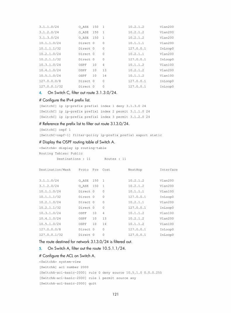
121
3.1.1.0/24 O_ASE 150 1 10.2.1.2 Vlan200
3.1.2.0/24 O_ASE 150 1 10.2.1.2 Vlan200
3.1.3.0/24 O_ASE 150 1 10.2.1.2 Vlan200
10.1.1.0/24 Direct 0 0 10.1.1.1 Vlan200
10.1.1.1/32 Direct 0 0 127.0.0.1 InLoop0
10.2.1.0/24 Direct 0 0 10.2.1.1 Vlan200
10.2.1.1/32 Direct 0 0 127.0.0.1 InLoop0
10.3.1.0/24 OSPF 10 4 10.1.1.2 Vlan100
10.4.1.0/24 OSPF 10 13 10.2.1.2 Vlan200
10.5.1.0/24 OSPF 10 14 10.1.1.2 Vlan100
127.0.0.0/8 Direct 0 0 127.0.0.1 InLoop0
127.0.0.1/32 Direct 0 0 127.0.0.1 InLoop0
4. On Switch C, filter out route 3.1.3.0/24.
# Configure the IPv4 prefix list. [SwitchC] ip ip-prefix prefix1 index 1 deny 3.1.3.0 24
[SwitchC] ip ip-prefix prefix1 index 2 permit 3.1.1.0 24
[SwitchC] ip ip-prefix prefix1 index 3 permit 3.1.2.0 24
# Reference the prefix list to filter out route 3.1.3.0/24. [SwitchC] ospf 1
[SwitchC-ospf-1] filter-policy ip-prefix prefix1 export static
# Display the OSPF routing table of Switch A. <SwitchA> display ip routing-table
Routing Tables: Public
Destinations : 11 Routes : 11
Destination/Mask Proto Pre Cost NextHop Interface
3.1.1.0/24 O_ASE 150 1 10.2.1.2 Vlan200
3.1.2.0/24 O_ASE 150 1 10.2.1.2 Vlan200
10.1.1.0/24 Direct 0 0 10.1.1.1 Vlan100
10.1.1.1/32 Direct 0 0 127.0.0.1 InLoop0
10.2.1.0/24 Direct 0 0 10.2.1.1 Vlan200
10.2.1.1/32 Direct 0 0 127.0.0.1 InLoop0
10.3.1.0/24 OSPF 10 4 10.1.1.2 Vlan100
10.4.1.0/24 OSPF 10 13 10.2.1.2 Vlan200
10.5.1.0/24 OSPF 10 14 10.1.1.2 Vlan100
127.0.0.0/8 Direct 0 0 127.0.0.1 InLoop0
127.0.0.1/32 Direct 0 0 127.0.0.1 InLoop0
The route destined for network 3.1.3.0/24 is filtered out.
5. On Switch A, filter out the route 10.5.1.1/24.
# Configure the ACL on Switch A. <SwitchA> system-view
[SwitchA] acl number 2000
[SwitchA-acl-basic-2000] rule 0 deny source 10.5.1.0 0.0.0.255
[SwitchA-acl-basic-2000] rule 1 permit source any
[SwitchA-acl-basic-2000] quit

122
# Use the ACL to filter route 10.5.1.0/24. [SwitchA] ospf 1
[SwitchA-ospf-1] filter-policy 2000 import
[SwitchA-ospf-1] quit
# Display the OSPF routing table of Switch A. [SwitchA] display ip routing-table
Routing Tables: Public
Destinations : 10 Routes : 10
Destination/Mask Proto Pre Cost NextHop Interface
3.1.1.0/24 O_ASE 150 1 10.2.1.2 Vlan200
3.1.2.0/24 O_ASE 150 1 10.2.1.2 Vlan200
10.1.1.0/24 Direct 0 0 10.1.1.1 Vlan100
10.1.1.1/32 Direct 0 0 127.0.0.1 InLoop0
10.2.1.0/24 Direct 0 0 10.2.1.1 Vlan200
10.2.1.1/32 Direct 0 0 127.0.0.1 InLoop0
10.3.1.0/24 OSPF 10 4 10.1.1.2 Vlan100
10.4.1.0/24 OSPF 10 13 10.2.1.2 Vlan200
127.0.0.0/8 Direct 0 0 127.0.0.1 InLoop0
127.0.0.1/32 Direct 0 0 127.0.0.1 InLoop0
The route destined for 10.5.1.1/24 is filtered out.
Configuring OSPF FRR Network requirements
Switch S, Switch A, and Switch D belong to the same OSPF domain as illustrated in Figure 47. Configure OSPF FRR so that when the link between Switch S and Switch D fails, traffic can be switched to Link B immediately.
Figure 47 Network diagram
Switch S Switch D
Switch A
Loop 01.1.1.1/32
Vlan-int100
12.12.12.1/24
Vlan-int20013.13.13.1/24
Vlan-int20013.13.13.2/24
Vlan-int100
12.12.12.2/24Vlan-int101
24.24.24.2/24 Vlan-int101
24.24.24.4/24Loop 0
4.4.4.4/32
Link A
Link B
Configuration procedure
1. Configure IP addresses for the interfaces on each switch and configure OSPF.
Follow Figure 47 to configure the IP address and subnet mask of each interface on the switches. (Details not shown)
Configure OSPF on the switches, ensuring that Switch S, Switch A, and Switch D can communicate with each other at Layer 3. (Details not shown)

123
2. Configure OSPF FRR.
You can enable OSPF FRR to either automatically calculate a backup next hop, or to designate a backup next hop by using a routing policy.
Method I: Enable OSPF FRR to automatically calculate the backup next hop.
# Configure Switch S. <SwitchS> system-view
[SwitchS] bfd echo-source-ip 1.1.1.1
[SwitchS] ospf 1
[SwitchS-ospf-1] fast-reroute auto
[SwitchS-ospf-1] quit
# Configure Switch D. <SwitchD> system-view
[SwitchD] bfd echo-source-ip 4.4.4.4
[SwitchD] ospf 1
[SwitchD-ospf-1] fast-reroute auto
[SwitchD-ospf-1] quit
Method II: Enable OSPF FRR to designate a backup next hop by using a routing policy.
# Configure Switch S. <SwitchS> system-view
[SwitchS] bfd echo-source-ip 1.1.1.1
[SwitchS] ip ip-prefix abc index 10 permit 4.4.4.4 32
[SwitchS] route-policy frr permit node 10
[SwitchS-route-policy] if-match ip-prefix abc
[SwitchS-route-policy] apply fast-reroute backup-interface vlan-interface 100 backup-nexthop 12.12.12.2
[SwitchS-route-policy] quit
[SwitchS] ospf 1
[SwitchS-ospf-1] fast-reroute route-policy frr
[SwitchS-ospf-1] quit
# Configure Switch D. <SwitchD> system-view
[SwitchD] bfd echo-source-ip 4.4.4.4
[SwitchD] ip ip-prefix abc index 10 permit 1.1.1.1 32
[SwitchD] route-policy frr permit node 10
[SwitchD-route-policy] if-match ip-prefix abc
[SwitchD-route-policy] apply fast-reroute backup-interface vlan-interface 101 backup-nexthop 24.24.24.2
[SwitchD-route-policy] quit
[SwitchD] ospf 1
[SwitchD-ospf-1] fast-reroute route-policy frr
[SwitchD-ospf-1] quit
3. Verify the configuration.
# Display route 4.4.4.4/32 on Switch S and you can view the backup next hop information. [SwitchS] display ip routing-table 4.4.4.4 verbose
Routing Table : Public
Summary Count : 1

124
Destination: 4.4.4.4/32
Protocol: OSPF Process ID: 1
Preference: 10 Cost: 1
IpPrecedence: QosLcId:
NextHop: 13.13.13.2 Interface: Vlan-interface200
BkNextHop: 12.12.12.2 BkInterface: Vlan-interface100
RelyNextHop: 0.0.0.0 Neighbor : 0.0.0.0
Tunnel ID: 0x0 Label: NULL
BKTunnel ID: 0x0 BKLabel: NULL
State: Active Adv Age: 00h01m27s
Tag: 0
# Display route 1.1.1.1/32 on Switch D. You can find the backup next hop information. [SwitchD] display ip routing-table 1.1.1.1 verbose
Routing Table : Public
Summary Count : 1
Destination: 1.1.1.1/32
Protocol: OSPF Process ID: 1
Preference: 10 Cost: 1
IpPrecedence: QosLcId:
NextHop: 13.13.13.1 Interface: Vlan-interface200
BkNextHop: 24.24.24.2 BkInterface: Vlan-interface101
RelyNextHop: 0.0.0.0 Neighbor : 0.0.0.0
Tunnel ID: 0x0 Label: NULL
BKTunnel ID: 0x0 BKLabel: NULL
State: Active Adv Age: 00h01m27s
Tag: 0
Configuring BFD for OSPF Network requirements
As shown in Figure 48, OSPF is enabled on Switch A, Switch B and Switch C that are reachable to each other at the network layer.
After the link over which Switch A and Switch B communicate through a Layer 2 switch fails, BFD can quickly detect the failure and notify OSPF of the failure. Switch A and Switch B then communicate through Switch C.

125
Figure 48 Network diagram
Device Interface IP address Device Interface IP address Switch A Vlan-int10 10.1.0.102/24 Switch B Vlan-int10 10.1.0.100/24 Vlan-int11 11.1.1.1/24 Vlan-int13 13.1.1.1/24 Switch C Vlan-int11 11.1.1.2/24 Vlan-int13 13.1.1.2/24
Configuration procedure
1. Configure IP addresses for interfaces. (Details not shown)
2. Configure OSPF basic functions.
# Configure Switch A. <SwitchA> system-view
[SwitchA] ospf
[SwitchA-ospf-1] area 0
[SwitchA-ospf-1-area-0.0.0.0] network 10.1.0.0 0.0.0.255
[SwitchA-ospf-1-area-0.0.0.0] network 11.1.1.0 0.0.0.255
[SwitchA-ospf-1-area-0.0.0.0] network 121.1.1.0 0.0.0.255
[SwitchA-ospf-1-area-0.0.0.0] quit
[SwitchA-ospf-1] quit
[SwitchA] interface vlan 11
[SwitchA-Vlan-interface11] ospf cost 2
[SwitchA-Vlan-interface11] quit
# Configure Switch B. <SwitchB> system-view
[SwitchB] ospf
[SwitchB-ospf-1] area 0
[SwitchB-ospf-1-area-0.0.0.0] network 10.1.0.0 0.0.0.255
[SwitchB-ospf-1-area-0.0.0.0] network 13.1.1.0 0.0.0.255
[SwitchB-ospf-1-area-0.0.0.0] network 120.1.1.0 0.0.0.255
[SwitchB-ospf-1-area-0.0.0.0] quit
[SwitchB-ospf-1] quit
[SwitchB] interface vlan-interface 13
[SwitchB-Vlan-interface13] ospf cost 2
[SwitchB-Vlan-interface13] quit
# Configure Switch C.

126
<SwitchC> system-view
[SwitchC] ospf
[SwitchC-ospf-1] area 0
[SwitchC-ospf-1-area-0.0.0.0] network 11.1.1.0 0.0.0.255
[SwitchC-ospf-1-area-0.0.0.0] network 13.1.1.0 0.0.0.255
[SwitchC-ospf-1-area-0.0.0.0] quit
[SwitchC-ospf-1] quit
3. Configure BFD.
# Enable BFD on Switch A and configure BFD parameters. [SwitchA] bfd session init-mode active
[SwitchA] interface vlan-interface 10
[SwitchA-Vlan-interface10] ospf bfd enable
[SwitchA-Vlan-interface10] bfd min-transmit-interval 500
[SwitchA-Vlan-interface10] bfd min-receive-interval 500
[SwitchA-Vlan-interface10] bfd detect-multiplier 7
[SwitchA-Vlan-interface10] quit
[SwitchA] quit
# Enable BFD on Switch B and configure BFD parameters. [SwitchB] bfd session init-mode active
[SwitchB] interface vlan-interface 10
[SwitchB-Vlan-interface10] ospf bfd enable
[SwitchB-Vlan-interface10] bfd min-transmit-interval 500
[SwitchB-Vlan-interface10] bfd min-receive-interval 500
[SwitchB-Vlan-interface10] bfd detect-multiplier 6
4. Verify the configuration.
The following operations are performed on Switch A. The operations on Switch B and Switch C are similar, and are not shown.
# Display the BFD information of Switch A. <SwitchA> display bfd session
Total Session Num: 1 Init Mode: Active
Session Working Under Ctrl Mode:
LD/RD SourceAddr DestAddr State Holdtime Interface
3/1 10.1.0.102 10.1.0.100 Up 1700ms vlan10
# Display routes to 120.1.1.0/24 on Switch A, and you can see that Switch A communicates with Switch B through the Layer 2 switch. <SwitchA> display ip routing-table 120.1.1.0 verbose
Routing Table : Public
Summary Count : 2
Destination: 120.1.1.0/24
Protocol: OSPF Process ID: 0
Preference: 0 Cost: 2
IpPrecedence: QosLcId:
NextHop: 192.168.0.100 Interface: Vlan-interface10
BkNextHop: 0.0.0.0 BkInterface:
RelyNextHop: 0.0.0.0 Neighbor : 0.0.0.0
Tunnel ID: 0x0 Label: NULL

127
BKTunnel ID: 0x0 BKLabel: NULL
State: Active Adv Age: 00h58m10s
Tag: 0
Destination: 120.1.1.0/24
Protocol: OSPF Process ID: 1
Preference: 10 Cost: 4
IpPrecedence: QosLcId:
NextHop: 10.1.1.100 Interface: Vlan-interface11
BkNextHop: 0.0.0.0 BkInterface:
RelyNextHop: 0.0.0.0 Neighbor : 0.0.0.0
Tunnel ID: 0x0 Label: NULL
BKTunnel ID: 0x0 BKLabel: NULL
State: Invalid Adv Age: 00h58m05s
Tag: 0
# Enable BFD debugging on Switch A. <SwitchA> debugging bfd scm
<SwitchA> debugging bfd event
<SwitchA> debugging ospf event
<SwitchA> terminal debugging
# After the link over which Switch A and Switch B communicates through the Layer 2 switch fails, Switch A can quickly detect the changes on Switch B. %Nov 12 18:34:48:823 2005 SwitchA BFD/5/LOG: Sess[10.1.0.102/10.1.0.100, vlan10], Sta : UP->DOWN, Diag: 1
%Nov 12 18:34:48:824 2005 SwitchA RM/4/RMLOG:OSPF-NBRCHANGE: Process 1, Neighbour 10.1.0.102 (vlan10) from Full to Down
*0.50673825 SwitchA BFD/8/SCM:Sess[10.1.0.102/10.1.0.100, vlan10],Oper: Reset
*0.50673825 SwitchA BFD/8/EVENT:Send sess-down Msg, [Src:10.1.0.102, Dst:10.1.0.100, vlan10] Protocol: OSPF
*0.50673826 SwitchA RM/7/RMDEBUG:OSPF-BFD: Message Type rcv BFD down, Connect Type direct-connect, Src IP Address 10.1.0.102, Src IFIndex 5, Dst IP Address 10.1.0.100
*0.50673827 SwitchA RM/7/RMDEBUG:OSPF-BFD: Message Type delete session, Connect Type direct-connect, Src IP Address 10.1.0.102, Src IFIndex 5, Dst IP Address 10.1.0.100
OSPF 1: Nbr 10.1.0.100 Rcv KillNbr State Full -> Down.
*0.50673829 SwitchA BFD/8/EVENT:Receive Delete-sess, [Src:10.1.0.102, Dst:10.1.0.100, vlan10], Direct, Proto:OSPF
*0.50673830 SwitchA BFD/8/SCM:Sess[10.1.0.102/10.1.0.100, vlan10], Oper: Del application(OSPF)
*0.50673831 SwitchA BFD/8/SCM:No application in session, delete session[10.1.0.102/10.1.0.100, vlan10]
*0.50673831 SwitchA BFD/8/SCM:Sess[10.1.0.102/10.1.0.100, vlan10], Oper: Delete
*0.50673832 SwitchA BFD/8/SCM:Delete send-packet timer
*0.50673833 SwitchA BFD/8/SCM:Delete session entry
*0.50673833 SwitchA BFD/8/SCM:Delete session from IP hash table
*0.50673834 SwitchA BFD/8/SCM:Delete session from bfd interface
*0.50673834 SwitchA BFD/8/SCM:No session under bfd-int[vlan10] with default configuration, delete bfd-if
*0.50673835 SwitchA BFD/8/SCM:Bfd-if[vlan10], Oper: Delete

128
*0.50673840 SwitchA BFD/8/SCM:No bfd session exists, stop receiving any bfd packets
# Display the BFD information of Switch A.
The BFD session between Switch A and Switch B is deleted and no information is output. <SwitchA> display bfd session
# Display routes to 120.1.1.0/24 on Switch A, and you can see that Switch A communicates with Switch B through Switch C. <SwitchA> display ip routing-table 120.1.1.0 verbose
Routing Table : Public
Summary Count : 2
Destination: 120.1.1.0/24
Protocol: OSPF Process ID: 1
Preference: 10 Cost: 4
IpPrecedence: QosLcId:
NextHop: 10.1.1.100 Interface: Vlan-interface11
BkNextHop: 0.0.0.0 BkInterface:
RelyNextHop: 0.0.0.0 Neighbor : 0.0.0.0
Tunnel ID: 0x0 Label: NULL
BKTunnel ID: 0x0 BKLabel: NULL
State: Active Adv Age: 00h58m10s
Tag: 0
Destination: 120.1.1.0/24
Protocol: OSPF Process ID: 0
Preference: 0 Cost: 2
IpPrecedence: QosLcId:
NextHop: 192.168.0.100 Interface: Vlan-interface10
BkNextHop: 0.0.0.0 BkInterface:
RelyNextHop: 0.0.0.0 Neighbor : 0.0.0.0
Tunnel ID: 0x0 Label: NULL
BKTunnel ID: 0x0 BKLabel: NULL
State: Invalid Adv Age: 00h58m05s
Tag: 0
Troubleshooting OSPF configuration
No OSPF neighbor relationship established Symptom
No OSPF neighbor relationship can be established.
Analysis
If the physical link and lower layer protocols work well, check OSPF parameters configured on interfaces. Two neighbors must have the same parameters, such as the area ID, network segment, and mask (a P2P or virtual link may have different network segments and masks).
Solution
1. Display OSPF neighbor information using the display ospf peer command.

129
2. Display OSPF interface information using the display ospf interface command.
3. Ping the neighbor router’s IP address to check connectivity.
4. Check OSPF timers. The dead interval on an interface must be at least four times the hello interval.
5. On an NBMA network, using the peer ip-address command to specify the neighbor manually is required.
6. On an NBMA or a broadcast network, at least one connected interface must have a router priority higher than 0.
Incorrect routing information Symptom
OSPF cannot find routes to other areas.
Analysis
The backbone area must maintain connectivity to all other areas. If a router connects to more than one area, at least one area must be connected to the backbone. The backbone cannot be configured as a Stub area.
In a Stub area, all routers cannot receive external routes, and all interfaces connected to the Stub area must belong to the Stub area.
Solution
1. Use the display ospf peer command to display neighbors.
2. Use the display ospf interface command to display OSPF interface information.
3. Use the display ospf lsdb command to display the LSDB to check its integrity.
4. Display information about area configuration using the display current-configuration configuration ospf command. If more than two areas are configured, at least one area is connected to the backbone.
5. In a Stub area, all routers attached are configured with the stub command. In an NSSA area, all routers attached are configured with the nssa command.
6. If a virtual link is configured, use the display ospf vlink command to check the state of the virtual link.

130
IS-IS configuration
NOTE:
• The term router in this document refers to both routers and Layer 3 switches.
• The 3600 v2 SI Switch Series does not support IS-IS.
IS-IS overview Intermediate System-to-Intermediate System (IS-IS) is a dynamic routing protocol designed by the International Organization for Standardization (ISO) to operate on the connectionless network protocol (CLNP).
The IS-IS routing protocol was modified and extended in RFC 1195 by the International Engineer Task Force (IETF) for application in both TCP/IP and OSI reference models, and the new one is named “Integrated IS-IS” or “Dual IS-IS”.
IS-IS is an Interior Gateway Protocol (IGP) used within an Autonomous System. It adopts the Shortest Path First (SPF) algorithm for route calculation.
Basic concepts IS-IS terminology
• Intermediate system (IS): Similar to a router in TCP/IP, it is the basic unit in IS-IS to generate and propagate routing information. In the following text, an IS refers to a router.
• End system (ES): Refers to a host system in TCP/IP. ISO defines the ES-IS protocol for communication between an ES and an IS. An ES does not participate in the IS-IS processing.
• Routing domain (RD): A group of ISs exchanges routing information with each other using the same routing protocol in a routing domain.
• Area: A unit in a routing domain. The IS-IS protocol allows a routing domain to be divided into multiple areas.
• Link State Database (LSDB): All link states in the network forms the LSDB. Each IS has at least one LSDB. The IS uses the SPF algorithm and LSDB to generate its own routes.
• Link State Protocol Data Unit (LSPDU) or Link State Packet (LSP): Each IS can generate an LSP, which contains all the link state information of the IS.
• Network Protocol Data Unit (NPDU): A network layer protocol packet in OSI, which is equivalent to an IP packet in TCP/IP.
• Designated IS: On a broadcast network, the designated router is also known as the “designated IS”.
• Network service access point (NSAP): An NSAP is an OSI network layer address. It identifies an abstract network service access point and describes the network address in the OSI reference model.

131
IS-IS address format
1. NSAP
As shown in Figure 49, an NSAP address consists of the Initial Domain Part (IDP) and the Domain Specific Part (DSP). The IDP is equal to the network ID of an IP address, and the DSP is equal to the subnet and host ID.
The IDP includes the Authority and Format Identifier (AFI) and the Initial Domain Identifier (IDI).
The DSP includes the High Order Part of DSP (HO-DSP), System ID, and SEL, where the HO-DSP identifies the area, the System ID identifies the host, and the SEL identifies the type of service.
The IDP and DSP are variable in length. The length of an NSAP address varies from 8 bytes to 20 bytes.
Figure 49 NSAP address format
2. Area address
The area address comprises the IDP and the HO-DSP of the DSP, which identify the area and the routing domain. Different routing domains cannot have the same area address.
Typically, a router only needs one area address, and all nodes in the same routing domain must share the same area address. However, a router can have a maximum of three area addresses to support smooth area merging, partitioning, and switching.
3. System ID
A system ID identifies a host or router uniquely. It has a fixed length of 48 bits (6 bytes).
The system ID of a device can be generated from the Router ID. For example, a router uses the IP address 168.10.1.1 of Loopback 0 as the Router ID. The system ID in IS-IS can be obtained in the following ways:
• Extend each decimal number of the IP address to 3 digits by adding 0s from the left, like 168.010.001.001;
• Divide the extended IP address into 3 sections with 4 digits in each section to get the system ID 1680.1000.1001.
If you use other methods for defining a system ID, always make sure that it can uniquely identify a host or router.
4. SEL
The NSAP Selector (SEL), or the N-SEL, is similar to the protocol identifier in IP. Different transport layer protocols correspond to different SELs. All SELs in IP are 00.
5. Routing method
Because the area information is identified in IS-IS addresses, a Level-1 router can easily identify packets destined to other areas.
• A Level-1 router makes routing decisions based on the system ID. If the destination is not in the area, the packet is forwarded to the nearest Level-1-2 router.
• A Level-2 router routes packets across areas according to the area address.

132
NET
A network entity title (NET) indicates the network layer information of an IS, and does not include transport layer information. It is a special NSAP address with the SEL being 0. The length of the NET is equal to the NSAP, and is in the range of 8 bytes to 20 bytes.
A NET comprises the following parts:
• Area ID—Its length is in the range of 1 to 13 bytes.
• System ID—A system ID uniquely identifies a host or router in the area and has a fixed 6-byte length.
• SEL—It has a value of 0 and a fixed 1-byte length.
For example, a NET is ab.cdef.1234.5678.9abc.00, where, area ID is ab.cdef, system ID is 1234.5678.9abc, and SEL is 00.
Typically, a router only needs one NET, but it can have a maximum of three NETs for smooth area merging and partitioning. When you configure multiple NETs, ensure their system IDs are the same.
IS-IS area Two-level hierarchy
IS-IS has a two-level hierarchy to support large scale networks. A large scale routing domain is divided into multiple Areas. Typically, a Level-1 router is deployed within an area, a Level-2 router is deployed between areas, and a Level-1-2 router is deployed between Level-1 and Level-2 routers.
Level-1 and Level-2
1. Level-1 router
A Level-1 router establishes neighbor relationships with Level-1 and Level-1-2 routers in the same area. The LSDB maintained by the Level-1 router contains the local area routing information. It directs the packets destined for an outside area to the nearest Level-1-2 router.
2. Level-2 router
A Level-2 router establishes neighbor relationships with the Level-2 and Level-1-2 routers in the same or in different areas. It maintains a Level-2 LSDB containing inter-area routing information. All the Level-2 and Level-1-2 routers must be contiguous to form the backbone of a routing domain.
3. Level-1-2 router
A router with both Level-1 and Level-2 router functions is a Level-1-2 router. It can establish Level-1 neighbor relationships with the Level-1 and Level-1-2 routers in the same area, or establish Level-2 neighbor relationships with the Level-2 and Level-1-2 routers in different areas. A Level-1 router must be connected to other areas through a Level-1-2 router. The Level-1-2 router maintains two LSDBs, where the Level-1 LSDB is for routing within the area, and the Level-2 LSDB is for routing between areas.
NOTE:
• The Level-1 routers in different areas cannot establish neighbor relationships.
• The neighbor relationship establishment of Level-2 routers has nothing to do with area.
Figure 50 shows an IS-IS network topology. Area 1 comprises a set of Level-2 routers and is the backbone. The other four areas are non-backbone areas connected to the backbone through Level-1-2 routers.

133
Figure 50 IS-IS topology 1
Figure 51 is another IS-IS topology. The Level-1-2 routers connect to the Level-1 and Level-2 routers, and form the IS-IS backbone together with the Level-2 routers. No area is defined as the backbone in this topology. The backbone comprises all contiguous Level-2 and Level-1-2 routers, which can reside in different areas.
Figure 51 IS-IS topology 2
NOTE:
The IS-IS backbone does not need to be a specific area.
Both the Level-1 and Level-2 routers use the SPF algorithm to generate the shortest path tree (SPT).
Route leaking
An IS-IS routing domain is comprised of only one Level-2 area and multiple Level-1 areas. A Level-1 area consists of a group of Level-1 routers, and is connected with a Level-2 area rather than other Level-1 areas.

134
The routing information of a Level-1 area is sent to the Level-2 area through the Level-1-2 router; therefore, the Level-2 router knows the routing information of the entire IS-IS routing domain. But the Level-1-2 router does not share the information of other Level-1 areas and the Level-2 area with the Level-1 area by default.
Because a Level-1 router simply sends packets destined for other areas to the nearest Level-1-2 router, the best paths may not be selected. To resolve this problem, route leaking was introduced. A Level-2 router can advertise Level-2 routing information to a specified Level-1 area. By having the routing information of other areas, a Level-1 router in the area can make a better routing decision for a packet to another area.
IS-IS network type Network type
IS-IS supports the following network types:
• Broadcast network—such as Ethernet and Token-Ring
• Point-to-point network—such as PPP and HDLC
DIS and pseudonodes
On an IS-IS broadcast network, a router is elected as the Designated Intermediate System (DIS).
The Level-1 and Level-2 DISs are elected respectively. You can assign different priorities for different level DIS elections. The higher a router’s priority is, the more likely the router becomes the DIS. If multiple routers with the same highest DIS priority exist, the one with the highest SNPA (Subnetwork Point of Attachment) address (MAC address on a broadcast network) will be elected. A router can be the DIS for different levels.
IS-IS DIS election differs from OSPF DIS election in the following ways:
• A router with priority 0 can also participate in the DIS election.
• When a router is added to the network and becomes the new DIS, an LDP flooding process is triggered.
As shown in Figure 52, the same level routers on a network, including non-DIS routers, establish adjacencies with each other.
Figure 52 DIS in the IS-IS broadcast network
The DIS creates and updates pseudonodes, as well as generates their LSPs, to describe all routers on the network.
A pseudonode represents a virtual node on the broadcast network. It is not a real router. In IS-IS, it is identified by the system ID of the DIS and a one-byte Circuit ID (a non zero value).
Using pseudonodes can reduce the resources consumed by SPF and simplify network topology.

135
NOTE:
On IS-IS broadcast networks, all routers are adjacent with each other. However, the DIS is responsible forthe synchronization of their LSDBs.
IS-IS PDU format PDU header format
IS-IS packets are encapsulated into link layer frames. The Protocol Data Unit (PDU) consists of two parts, the headers and the variable length fields. The headers comprise the PDU common header and the PDU specific header. All PDUs have the same PDU common header. The specific headers vary by PDU type.
Figure 53 PDU format
Common header format
Figure 54 PDU common header format
Intradomain routing protocol discriminator
Reserved
Version
R
ID length
Version/Protocol ID extension
Length indicator
Maximum area address
R R PDU type
No. of Octets1
1
1
1
1
1
1
1
Major fields of the PDU common header are as follows:
• Intradomain routing protocol discriminator—Set to 0x83
• Length indicator—Length of the PDU header in bytes, including both common and specific headers
• Version/Protocol ID extension—Set to 1(0x01)
• ID length—Length of the NSAP address and NET ID
• R (Reserved)—Set to 0
• PDU type—See Table 2.
• Version—Set to 1(0x01)
• Maximum area address—Maximum number of area addresses supported
Table 2 PDU type
Type PDU Type Acronym
15 Level-1 LAN IS-IS hello PDU L1 LAN IIH
16 Level-2 LAN IS-IS hello PDU L2 LAN IIH

136
Type PDU Type Acronym
17 Point-to-Point IS-IS hello PDU P2P IIH
18 Level-1 Link State PDU L1 LSP
20 Level-2 Link State PDU L2 LSP
24 Level-1 Complete Sequence Numbers PDU L1 CSNP
25 Level-2 Complete Sequence Numbers PDU L2 CSNP
26 Level-1 Partial Sequence Numbers PDU L1 PSNP
27 Level-2 Partial Sequence Numbers PDU L2 PSNP
Hello
Hello packets are used by routers to establish and maintain neighbor relationships. A hello packet is also an IS-to-IS hello PDU (IIH). For broadcast networks, the Level-1 routers use the Level-1 LAN IIHs; and the Level-2 routers use the Level-2 LAN IIHs. The P2P IIHs are used on point-to-point networks.
Figure 55 illustrates the hello packet format in broadcast networks, where the blue fields are the common header.
Figure 55 L1/L2 LAN IIH format
Major fields of the L1/L2 LAN IIH are as follows:
• Reserved/Circuit type: The first six bits are reserved with a value of 0. The last two bits indicate the router type. Here, 00 means reserved, 01 indicates L1, 10 indicates L2, and 11 indicates L1/2.
• Source ID: System ID of the router advertising the hello packet.
• Holding time: If no hello packets are received from the neighbor within the holding time, the neighbor is considered down.
• PDU length: Total length of the PDU in bytes.
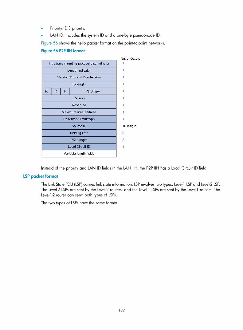
137
• Priority: DIS priority.
• LAN ID: Includes the system ID and a one-byte pseudonode ID.
Figure 56 shows the hello packet format on the point-to-point networks.
Figure 56 P2P IIH format
Instead of the priority and LAN ID fields in the LAN IIH, the P2P IIH has a Local Circuit ID field.
LSP packet format
The Link State PDU (LSP) carries link state information. LSP involves two types: Level-1 LSP and Level-2 LSP. The Level-2 LSPs are sent by the Level-2 routers, and the Level-1 LSPs are sent by the Level-1 routers. The Level-1-2 router can send both types of LSPs.
The two types of LSPs have the same format.

138
Figure 57 L1/L2 LSP format
Major fields of the L1/L2 LSP are as follows:
• PDU length: Total length of the PDU in bytes
• Remaining lifetime: LSP remaining lifetime in seconds
• LSP ID: Consists of the system ID, the pseudonode ID (one byte) and the LSP fragment number (one byte)
• Sequence number: LSP sequence number
• Checksum: LSP checksum
• P (Partition Repair): Only for L2 LSPs; it indicates whether the router supports partition repair.
• ATT (Attachment): Generated by a L1/L1 router for L1 LSPs only; it indicates that the router generating the LSP is connected to multiple areas.
• OL (LSDB Overload): Indicates that the LSDB is not complete because the router has run out of memory. Other routers will not send packets to the overloaded router, except packets destined to the networks directly connected to the router. For example, in Figure 58, Router A forwards packets to Router C through Router B. Once other routers know the OL field of LSPs from Router B is set to 1, Router A will send packets to Router C via Router D and Router E, but still send to Router B packets destined to the network directly connected to Router B.

139
Figure 58 LSDB overload
• IS type: Type of the router generating the LSP.
SNP format
A sequence number PDU (SNP) acknowledges the latest received LSPs. It is similar to an Acknowledge packet, but more efficient.
SNP involves Complete SNP (CSNP) and Partial SNP (PSNP), which are further divided into Level-1 CSNP, Level-2 CSNP, Level-1 PSNP and Level-2 PSNP.
CSNP covers the summary of all LSPs in the LSDB to synchronize the LSDB between neighboring routers. On broadcast networks, CSNP is sent by the DIS periodically (10s by default). On point-to-point networks, CSNP is only sent during the adjacency establishment.
The CSNP packet format is shown in Figure 59.
Figure 59 L1/L2 CSNP format
PSNP only contains the sequence numbers of one or multiple latest received LSPs. It can acknowledge multiple LSPs at one time. When LSDBs are not synchronized, a PSNP is used to request new LSPs from neighbors.

140
Figure 60 L1/L2 PSNP format
Intradomain routing protocol discriminator
Reserved
Version
R
ID length
Version/Protocol ID extension
Length indicator
Maximum area address
R R PDU type
No. of Octets1
1
1
1
1
1
1
1
PDU length
Source ID
Variable length fields
2
ID length+1
CLV
The variable fields of PDU comprise multiple Code-Length-Value (CLV) triplets.
Figure 61 CLV format
Table 3 shows that different PDUs contain different CLVs. Code 1 to 10 of CLV are defined in ISO 10589 (code 3 and 5 are not shown in the table), and others are defined in RFC 1195.
Table 3 CLV name and the corresponding PDU type
CLV Code Name PDU Type
1 Area Addresses IIH, LSP
2 IS Neighbors (LSP) LSP
4 Partition Designated Level2 IS L2 LSP
6 IS Neighbors (MAC Address) LAN IIH
7 IS Neighbors (SNPA Address) LAN IIH
8 Padding IIH
9 LSP Entries SNP
10 Authentication Information IIH, LSP, SNP
128 IP Internal Reachability Information LSP
129 Protocols Supported IIH, LSP
130 IP External Reachability Information L2 LSP
131 Inter-Domain Routing Protocol Information L2 LSP

141
CLV Code Name PDU Type
132 IP Interface Address IIH, LSP
Supported IS-IS features Multiple instances and processes
IS-IS supports multiple instances and processes. Multiple processes allow an IS-IS process to work in concert with a group of interfaces. A router can run multiple IS-IS processes, and each process corresponds to a unique group of interfaces.
For routers supporting VPN, each IS-IS process is associated with a VPN instance. The VPN instance is also associated with interfaces of the process.
IS-IS Graceful Restart
Graceful Restart (GR) ensures the continuity of packet forwarding when a routing protocol restarts or an active/standby switchover occurs:
• GR Restarter: Graceful restarting router. It must be GR capable.
• GR Helper: A neighbor of the GR Restarter. It helps the GR Restarter to complete the GR process.
After an IS-IS GR Restarter restarts, it must complete the following tasks to synchronize the LSDB with its neighbors:
• Obtain IS-IS neighbor information without changing adjacencies
• Obtain the LSDB
The GR Restarter sends an OSPF GR signal to GR Helpers so that the GR Helpers keep their adjacencies with the GR Restarter, and restores the neighbor table after receiving responses from neighbors. The GR Restarter then synchronizes the LSDB with all GR capable neighbors, calculates routes, updates its routing table and forwarding table, and removes stale routes. The IS-IS routing convergence is then complete.
IS-IS NSR
Nonstop routing (NSR) is a new feature that overcomes the application limit of GR. It backs up IS-IS link state information from the master device to the slave device. When a master/slave switchover occurs, NSR can complete link state recovery and route re-generation without requiring the cooperation of other devices.
Management tag
Management tag simplifies routing information management by carrying the management information of the IP address prefixes (to control route redistribution from other routing protocols) and BGP community and extended community attributes.
LSP fragment extension
IS-IS advertises link state information by flooding LSPs. Because one LSP carries a limited amount of link state information, IS-IS fragments LSPs. Each LSP fragment is uniquely identified by a combination of the System ID, Pseudonode ID (0 for a common LSP or a non-zero value for a Pseudonode LSP), and LSP Number (LSP fragment number) of the node or pseudo node that generated the LSP. The one-byte LSP Number field, allowing a maximum of only 256 fragments to be generated by an IS-IS router, limits the amount of link information the IS-IS router can advertise.

142
The LSP fragment extension feature allows an IS-IS router to generate more LSP fragments. Up to 50 additional virtual systems can be configured on the router, and each virtual system is capable of generating 256 LSP fragments to enable the IS-IS router to generate up to 13056 LSP fragments.
1. Terms
• Originating system
It is the router actually running IS-IS. After LSP fragment extension is enabled, additional virtual systems can be configured for the router. Originating system is the actual IS-IS process that originally runs.
• System ID
System ID of the originating system
• Additional system ID
Additional virtual system IDs are configured for the IS-IS router after LSP fragment extension is enabled. Each additional system ID can generate 256 LSP fragments. Both the additional system ID and the system ID must be unique in the entire routing domain.
• Virtual system
A virtual system is identified by an additional system ID and generates extended LSP fragments.
• Original LSP
The LSP generated by the originating system. The system ID in its LSP ID field is the system ID of the originating system.
• Extended LSP
Extended LSPs are generated by virtual systems. The system ID in its LSP ID field is the virtual system ID.
After additional system IDs are configured, an IS-IS router can advertise more link state information in extended LSP fragments. Each virtual system can be considered a virtual router. An extended LSP fragment is advertised by a virtual system identified by an additional system ID.
2. Operation modes
The LSP fragment extension feature operates in the following modes:
• Mode-1: Applicable to a network where some routers do not support LSP fragment extension. In this mode, adjacencies are formed between the originating system and virtual systems, with the link cost from the originating system to each virtual system as 0. Each virtual system acts as a router connected to the originating system in the network, but the virtual systems are reachable through the originating system only. The IS-IS routers not supporting LSP fragment extension can operate properly without modifying the extended LSP fragments received, but some limitation is imposed on the link state information in the extended LSP fragments advertised by the virtual systems.
• Mode-2: Applicable to a network where all the routers support LSP fragment extension. In this mode, all the IS-IS routers know which virtual system belongs to which originating system; no limitation is imposed on the link state information of the extended LSP fragments advertised by the virtual systems.
The operation mode of LSP fragment extension is configured based on area and routing level. Mode-1 allows the routers supporting and not supporting LSP fragment extension to interoperate with each other, but it restricts the link state information in the extended fragments. Mode-2 does not restrict the link state information in the extended fragments, and is recommended for an area where all the routers are at the same routing level and support LSP fragment extension.

143
Dynamic host name mapping mechanism
The dynamic host name mapping mechanism provides the mappings between the host names and the system IDs for the IS-IS routers. The dynamic host name information is announced in the dynamic host name CLV of an LSP.
This mechanism also provides the mapping between a host name and the DIS of a broadcast network, which is announced in the dynamic host name TLV of a pseudonode LSP.
A host name is easier to remember than a system ID. After enabling this feature on the router, you can see the host names instead of system IDs using the display command.
BFD
NOTE:
For more information about BFD, see High Availability Configuration Guide.
Bidirectional forwarding detection (BFD) provides a single mechanism to quickly detect any link failures between IS-IS neighbors to reduce network convergence time.
Protocols and standards • ISO 10589 ISO IS-IS Routing Protocol
• ISO 9542 ES-IS Routing Protocol
• ISO 8348/Ad2 Network Services Access Points
• RFC 1195, Use of OSI IS-IS for Routing in TCP/IP and Dual Environments
• RFC 2763, Dynamic Hostname Exchange Mechanism for IS-IS
• RFC 2966, Domain-wide Prefix Distribution with Two-Level IS-IS
• RFC 3277, IS-IS Transient Blackhole Avoidance
• RFC 3358, Optional Checksums in ISIS
• RFC 3373, Three-Way Handshake for IS-IS Point-to-Point Adjacencies
• RFC 3567, Intermediate System to Intermediate System (IS-IS) Cryptographic Authentication
• RFC 3719, Recommendations for Interoperable Networks using IS-IS
• RFC 3786, Extending the Number of IS-IS LSP Fragments Beyond the 256 Limit
• RFC 3787, Recommendations for Interoperable IP Networks using IS-IS
• RFC 3784, IS-IS extensions for Traffic Engineering
• RFC 3847, Restart signaling for IS-IS
IS-IS configuration task list Complete the following tasks to configure IS-IS:
Task Remarks
Configuring IS-IS basic functions
Enabling IS-IS
Required Configuring the IS level and circuit level
Configuring the network type of an interface as P2P

144
Task Remarks
Configuring IS-IS routing information control
Configuring IS-IS link cost Optional
Specifying a priority for IS-IS Required
Configuring the maximum number of equal cost routes Optional
Configuring IS-IS route summarization Optional
Advertising a default route Optional
Configuring IS-IS route redistribution Optional
Configuring IS-IS route filtering Optional
Configuring IS-IS route leaking Optional
Tuning and optimizing IS-IS networks
Specifying intervals for sending IS-IS hello and CSNP packets Optional
Specifying the IS-IS hello multiplier Optional
Configuring a DIS priority for an interface Optional
Disabling an interface from sending or receiving IS-IS packets Optional
Enabling an interface to send small hello packets Optional
Configuring LSP parameters Optional
Configuring SPF parameters Optional
Assigning a high priority to IS-IS routes Optional
Setting the LSDB overload bit Optional
Configuring system ID to host name mappings Optional
Enabling the logging of neighbor state changes Optional
Enhancing IS-IS network security
Configuring neighbor relationship authentication Optional
Configuring area authentication Optional
Configuring routing domain authentication Optional
Configuring IS-IS GR Optional
Configuring IS-IS NSR Optional
Configuring IS-IS FRR Optional
Enabling IS-IS SNMP trap Optional
Binding an IS-IS process with MIBs Optional
Configuring BFD for IS-IS Optional
Configuring IS-IS basic functions
Configuration prerequisites Before configuring IS-IS basic functions, complete the following tasks:
• Configure the link layer protocol

145
• Configure an IP address for each interface, and make sure all neighboring nodes are reachable to each other at the network layer.
Enabling IS-IS Follow these steps to enable IS-IS:
To do… Use the command… Remarks
Enter system view system-view —
Enable the IS-IS routing process and enter its view
isis [ process-id ] [ vpn-instance vpn-instance-name ]
Required
Not enabled by default
Assign a network entity title (NET) network-entity net Required
Not assigned by default
Return to system view quit —
Enter interface view interface interface-type interface-number
—
Enable an IS-IS process on the interface
isis enable [ process-id ] Required
Disabled by default
Configuring the IS level and circuit level If only one area is available, HP recommends you to perform the following operations:
• Configure the IS level of all routers as Level-1 or Level-2 rather than different levels because the routers do not need to maintain two identical LSDBs.
• Configure the IS level as Level-2 on all routers in an IP network for scalability.
For an interface of a Level-1 (or Level-2) router, the circuit level can only be Level-1 (or Level-2). For an interface of a Level-1-2 router, the default circuit level is Level-1-2; if the router only needs to form Level-1 (or Level-2) neighbor relationships, then configure the circuit level for its interfaces as Level-1 (or Level-2) to limit neighbor relationship establishment.
Follow these steps to configure the IS level and circuit level:
To do… Use the command… Remarks
Enter system view system-view —
Enter IS-IS view isis [ process-id ] [ vpn-instance vpn-instance-name ]
—
Specify the IS level is-level { level-1 | level-1-2 | level-2 }
Optional
The default is Level-1-2.
Return to system view quit —
Enter interface view interface interface-type interface-number
—
Specify the circuit level isis circuit-level [ level-1 | level-1-2 | level-2 ]
Optional
By default, an interface can establish the Level-1 or Level-2 adjacency.

146
Configuring the network type of an interface as P2P Interfaces with different network types operate differently. For example, broadcast interfaces on a network must elect the DIS and flood CSNP packets to synchronize the LSDBs, but P2P interfaces on a network do not need to elect the DIS, and have a different LSDB synchronization mechanism.
If only two routers exist on a broadcast network, configure the network type of attached interfaces as P2P to avoid DIS election and CSNP flooding, saving network bandwidth and speeding up network convergence.
Follow these steps to configure the network type of an interface:
To do… Use the command… Remarks
Enter system view system-view —
Enter interface view interface interface-type interface-number
—
Configure the network type for the interface as P2P isis circuit-type p2p
Optional
By default, the network type of an interface depends on the physical media. The network type of a VLAN interface is broadcast.
NOTE:
You can only perform this configuration for a broadcast network with only two attached routers.
Configuring IS-IS routing information control
Configuration prerequisites Before configuring IS-IS routing information control, complete the following tasks:
• Configure network layer addresses for interfaces, and ensure adjacent nodes are reachable to each other at the network layer.
• Enable IS-IS
Configuring IS-IS link cost The IS-IS cost of an interface is determined in the following order:
• IS-IS cost specified in interface view
• IS-IS cost specified in system view. The cost is applied to the interfaces associated with the IS-IS process.
• Automatically calculated cost—When the cost style is wide or wide-compatible, IS-IS automatically calculates the cost using the formula: interface cost = (bandwidth reference value/interface bandwidth) ×10. When the cost style is of another type: if the interface bandwidth does not exceed 10 Mbps, the interface cost equals 60; if the interface bandwidth does not exceed 100 Mbps, the interface cost equals 50; if the interface bandwidth does not exceed 155 Mbps, the interface cost

147
equals 40; if the interface bandwidth does not exceed 622 Mbps, the interface cost equals 30; if the interface bandwidth does not exceed 2500 Mbps, the interface cost equals 20; if the interface bandwidth exceeds 2500 Mbps, the interface cost equals 10.
If none of the above costs are used, a default cost of 10 applies.
Configuring an IS-IS cost for an interface
Follow these steps to configure a cost for an interface:
To do… Use the command… Remarks
Enter system view system-view —
Enter IS-IS view isis [ process-id ] [ vpn-instance vpn-instance-name ]
—
Specify an IS-IS cost style cost-style { narrow | wide | wide-compatible | { compatible | narrow-compatible } [ relax-spf-limit ] }
Optional
narrow by default
Return to system view quit —
Enter interface view interface interface-type interface-number —
Specify a cost for the interface isis cost value [ level-1 | level-2 ] Optional
No cost is specified for the interface by default.
Configuring a global IS-IS cost
Follow these steps to configure a global IS-IS cost:
To do… Use the command… Remarks
Enter system view system-view —
Enter IS-IS view isis [ process-id ] [ vpn-instance vpn-instance-name ] —
Specify an IS-IS cost style cost-style { narrow | wide | wide-compatible | { compatible | narrow-compatible } [ relax-spf-limit ] }
Optional
narrow by default
Specify a global IS-IS cost circuit-cost value [ level-1 | level-2 ]
Required
No global cost is specified by default.
Enable automatic IS-IS cost calculation
Follow these steps to enable automatic IS-IS cost calculation:
To do… Use the command… Remarks
Enter system view system-view —
Enter IS-IS view isis [ process-id ] [ vpn-instance vpn-instance-name ]
—
Specify an IS-IS cost style cost-style { wide | wide-compatible } Required
narrow by default
Enable automatic IS-IS cost calculation auto-cost enable
Required
Disabled by default

148
To do… Use the command… Remarks
Configure a bandwidth reference value for automatic IS-IS cost calculation
bandwidth-reference value Optional
100 Mbps by default
Specifying a priority for IS-IS A router can run multiple routing protocols. When routes to the same destination are found by multiple routing protocols, the route learned by the protocol with the highest priority can be adopted. You can reference a routing policy to specify a priority for specific routes. For information about routing policy, see the chapter “Routing policy configuration.”
Follow these steps to configure the priority of IS-IS.
To do… Use the command… Remarks
Enter system view system-view —
Enter IS-IS view isis [ process-id ] [ vpn-instance vpn-instance-name ] —
Specify a priority for IS-IS preference { route-policy route-policy-name | preference } *
Required
15 by default
Configuring the maximum number of equal cost routes If multiple equal cost routes reach the same destination, the traffic can be load balanced to enhance efficiency.
Follow these steps to configure the maximum number of equal cost routes:
To do… Use the command… Remarks
Enter system view system-view —
Enter IS-IS view isis [ process-id ] [ vpn-instance vpn-instance-name ]
—
Specify the maximum number of equal cost routes for load balancing
maximum load-balancing number Required
8 by default
Configuring IS-IS route summarization This task allows you to configure a summary route so routes falling into the network range of the summary route are summarized into one route for advertisement. Doing so can reduce the size of routing tables, as well as the scale of LSP and LSDB. Both IS-IS routes and redistributed routes can be summarized.
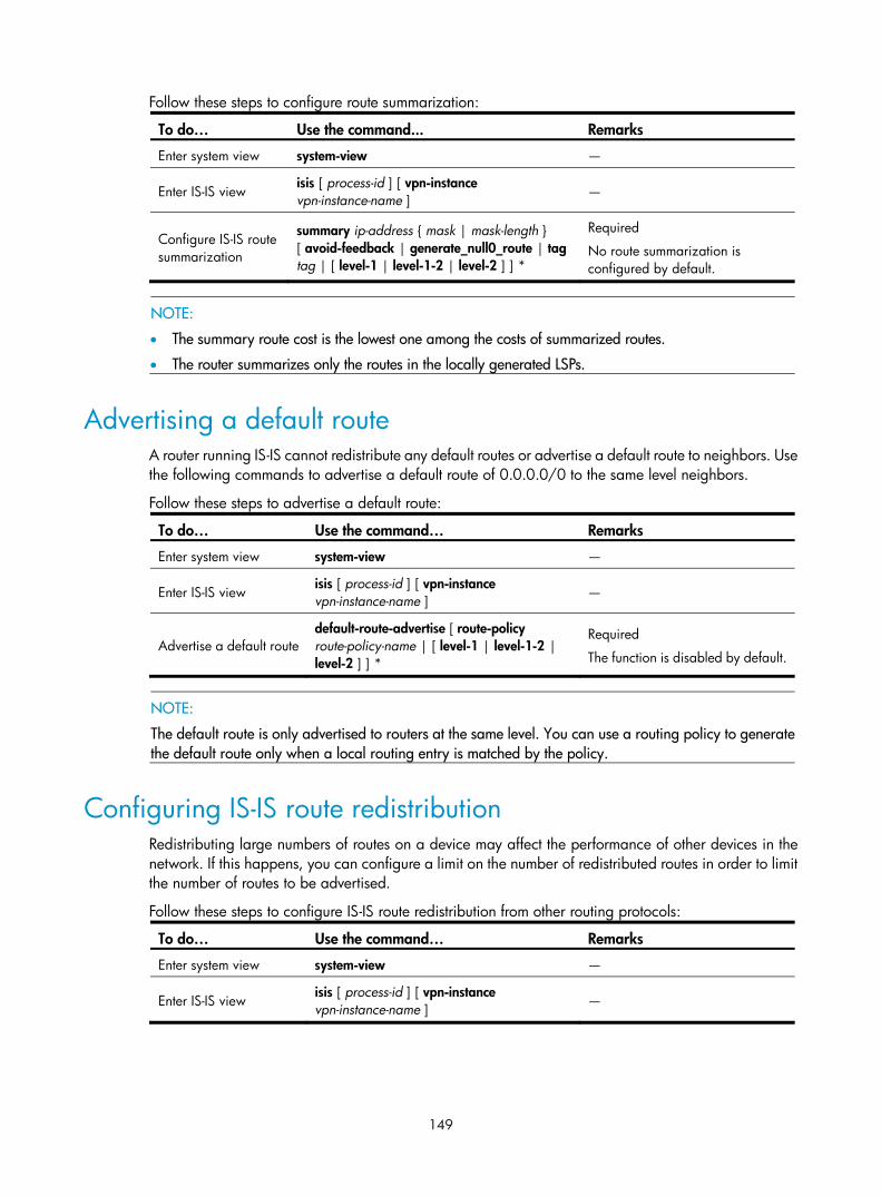
149
Follow these steps to configure route summarization:
To do… Use the command... Remarks
Enter system view system-view —
Enter IS-IS view isis [ process-id ] [ vpn-instance vpn-instance-name ]
—
Configure IS-IS route summarization
summary ip-address { mask | mask-length } [ avoid-feedback | generate_null0_route | tag tag | [ level-1 | level-1-2 | level-2 ] ] *
Required
No route summarization is configured by default.
NOTE:
• The summary route cost is the lowest one among the costs of summarized routes.
• The router summarizes only the routes in the locally generated LSPs.
Advertising a default route A router running IS-IS cannot redistribute any default routes or advertise a default route to neighbors. Use the following commands to advertise a default route of 0.0.0.0/0 to the same level neighbors.
Follow these steps to advertise a default route:
To do… Use the command… Remarks
Enter system view system-view —
Enter IS-IS view isis [ process-id ] [ vpn-instance vpn-instance-name ]
—
Advertise a default route default-route-advertise [ route-policy route-policy-name | [ level-1 | level-1-2 | level-2 ] ] *
Required
The function is disabled by default.
NOTE:
The default route is only advertised to routers at the same level. You can use a routing policy to generatethe default route only when a local routing entry is matched by the policy.
Configuring IS-IS route redistribution Redistributing large numbers of routes on a device may affect the performance of other devices in the network. If this happens, you can configure a limit on the number of redistributed routes in order to limit the number of routes to be advertised.
Follow these steps to configure IS-IS route redistribution from other routing protocols:
To do… Use the command… Remarks
Enter system view system-view —
Enter IS-IS view isis [ process-id ] [ vpn-instance vpn-instance-name ]
—

150
To do… Use the command… Remarks
Redistribute routes from another routing protocol
import-route protocol [ process-id | all-processes | allow-ibgp ] [ cost cost | cost-type { external | internal } | [ level-1 | level-1-2 | level-2 ] | route-policy route-policy-name | tag tag ] *
Required
No route is redistributed by default.
If no level is specified, routes are redistributed into the Level-2 routing table by default.
Configure the maximum number of redistributed Level 1/Level 2 IPv4 routes
import-route limit number Optional
The default varies with devices.
NOTE:
Only active routes can be redistributed. Use the display ip routing-table protocol command to display route state information.
Configuring IS-IS route filtering You can reference a configured ACL, IP prefix list, or routing policy to filter routes calculated from the received LSPs and the routes redistributed from other routing protocols.
Filtering routes calculated from received LSPs
IS-IS saves the LSPs received from neighbors in the LSDB, uses the SPF algorithm to calculate the shortest path tree with itself as the root, and installs the routes into the IS-IS routing table.
By referencing a configured ACL, IP prefix list, or routing policy, you can filter the calculated routes. Only the routes matching the filter can be added into the IS-IS routing table.
Follow these steps to filter routes calculated from received LSPs:
To do… Use the command… Remarks
Enter system view system-view —
Enter IS-IS view isis [ process-id ] [ vpn-instance vpn-instance-name ]
—
Filter routes calculated from received LSPs
filter-policy { acl-number | ip-prefix ip-prefix-name | route-policy route-policy-name } import
Required
No filtering is configured by default.
Filtering redistributed routes
IS-IS can redistribute routes from other routing protocols (or other IS-IS processes), add them into the IS-IS routing table, and advertise them in LSPs.
By reference a configured ACL, IP prefix list, or routing policy, you can filter redistributed routes and only the routes matching the filter can be added into the IS-IS routing table and advertised to neighbors.
Follow these steps to configure the filtering of redistributed routes:
To do… Use the command… Remarks
Enter system view system-view —
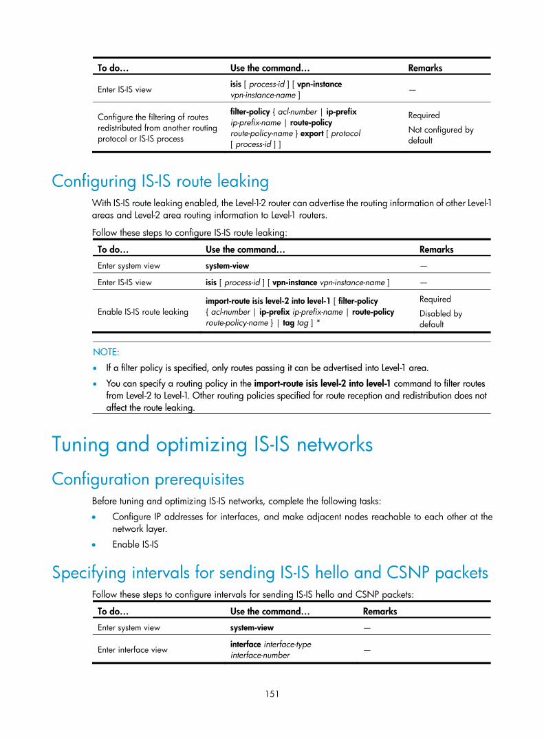
151
To do… Use the command… Remarks
Enter IS-IS view isis [ process-id ] [ vpn-instance vpn-instance-name ]
—
Configure the filtering of routes redistributed from another routing protocol or IS-IS process
filter-policy { acl-number | ip-prefix ip-prefix-name | route-policy route-policy-name } export [ protocol [ process-id ] ]
Required
Not configured by default
Configuring IS-IS route leaking With IS-IS route leaking enabled, the Level-1-2 router can advertise the routing information of other Level-1 areas and Level-2 area routing information to Level-1 routers.
Follow these steps to configure IS-IS route leaking:
To do… Use the command… Remarks
Enter system view system-view —
Enter IS-IS view isis [ process-id ] [ vpn-instance vpn-instance-name ] —
Enable IS-IS route leaking import-route isis level-2 into level-1 [ filter-policy { acl-number | ip-prefix ip-prefix-name | route-policy route-policy-name } | tag tag ] *
Required
Disabled by default
NOTE:
• If a filter policy is specified, only routes passing it can be advertised into Level-1 area.
• You can specify a routing policy in the import-route isis level-2 into level-1 command to filter routes from Level-2 to Level-1. Other routing policies specified for route reception and redistribution does not affect the route leaking.
Tuning and optimizing IS-IS networks
Configuration prerequisites Before tuning and optimizing IS-IS networks, complete the following tasks:
• Configure IP addresses for interfaces, and make adjacent nodes reachable to each other at the network layer.
• Enable IS-IS
Specifying intervals for sending IS-IS hello and CSNP packets Follow these steps to configure intervals for sending IS-IS hello and CSNP packets:
To do… Use the command… Remarks
Enter system view system-view —
Enter interface view interface interface-type interface-number
—

152
To do… Use the command… Remarks
Specify the interval for sending hello packets
isis timer hello seconds [ level-1 | level-2 ]
Optional
10 seconds by default
Specify the interval for sending CSNP packets on the DIS of a broadcast network
isis timer csnp seconds [ level-1 | level-2 ]
Optional
10 seconds by default
NOTE:
The interval between hello packets sent by the DIS is 1/3 the hello interval set with the isis timer hello command.
Specifying the IS-IS hello multiplier If a neighbor receives no hello packets from the router within the advertised hold time, it considers the router down and recalculates the routes. The hold time is the hello multiplier multiplied by the hello interval.
Follow these steps to specify the IS-IS hello multiplier:
To do… Use the command… Remarks
Enter system view system-view —
Enter interface view interface interface-type interface-number
—
Specify the number of hello packets a neighbor must miss before declaring the router is down
isis timer holding-multiplier value [ level-1 | level-2 ]
Optional
3 by default
NOTE:
On a broadcast link, Level-1 and Level-2 hello packets are advertised separately; therefore, you need toset a hello multiplier for each level. On a P2P link, Level-1 and Level-2 hello packets are advertised in P2Phello packets, so you do not need to specify Level-1 or Level-2.
Configuring a DIS priority for an interface On an IS-IS broadcast network, you must elect a router as the DIS at a routing level. You can specify a DIS priority at a level for an interface. The greater the interface’s priority, the more likely it becomes the DIS. If multiple routers in the broadcast network have the same highest DIS priority, the router with the highest MAC address becomes the DIS.
Follow these steps to specify a DIS priority for an interface:
To do… Use the command… Remarks
Enter system view system-view —
Enter interface view interface interface-type interface-number
—
Specify a DIS priority for the interface
isis dis-priority value [ level-1 | level-2 ]
Optional
64 by default

153
Disabling an interface from sending or receiving IS-IS packets After being disabled from sending or receiving hello packets, an interface cannot form a neighbor relationship, but can advertise directly connected networks in LSPs through other interfaces. This can save bandwidth and CPU resources, and ensures other routers know networks directly connected to the interface.
Follow these steps to disable an interface from sending and receiving IS-IS packets:
To do… Use the command… Remarks
Enter system view system-view —
Enter interface view interface interface-type interface-number
—
Disable the interface from sending and receiving IS-IS packets isis silent
Required
Not disabled by default
Enabling an interface to send small hello packets IS-IS messages cannot be fragmented at the IP layer because they are directly encapsulated into frames. Any two IS-IS neighboring routers must negotiate a common MTU. To avoid sending big hellos for saving bandwidth, enable the interface to send small hello packets without CLVs.
Follow these steps to enable an interface to send small hello packets:
To do… Use the command… Remarks
Enter system view system-view —
Enter interface view interface interface-type interface-number
—
Enable the interface to send small hello packets without CLVs isis small-hello
Required
Standard hello packets are sent by default.
Configuring LSP parameters Configuring LSP timers
1. Specify the maximum age of LSPs
Each LSP has an age that decreases in the LSDB. Any LSP with an age of 0 is deleted from the LSDB. You can adjust the age value based on the scale of a network.
Follow these steps to specify the maximum age of LSPs:
To do… Use the command… Remarks
Enter system view system-view —
Enter IS-IS view isis [ process-id ] [ vpn-instance vpn-instance-name ]
—
Specify the maximum LSP age timer lsp-max-age seconds Optional
1200 seconds by default

154
2. Specify the LSP refresh interval and generation interval
Each router needs to refresh LSPs generated by itself at a configurable interval and send them to other routers to prevent valid routes from being aged out. A smaller refresh interval speeds up network convergence but consumes more bandwidth.
When the network topology changes, for example, a neighbor is down or up, or the interface metric, system ID, or area ID is changed, the router generates an LSP after a configurable interval. If such a change occurs frequently, excessive LSPs are generated, consuming a large amount of router resources and bandwidth. To solve the problem, you can adjust the LSP generation interval.
Follow these steps to specify the LSP refresh interval and generation interval:
To do… Use the command… Remarks
Enter system view system-view —
Enter IS-IS view isis [ process-id ] [ vpn-instance vpn-instance-name ] —
Specify the LSP refresh interval timer lsp-refresh seconds Optional
900 seconds by default
Specify the LSP generation interval
timer lsp-generation maximum-interval [ initial-interval [ second-wait-interval ] ] [ level-1 | level-2 ]
Optional
2 seconds by default
3. Specify LSP sending intervals
If a change occurs in the LSDB, IS-IS advertises the changed LSP to neighbors. You can specify the minimum interval for sending such LSPs.
On a P2P link, IS-IS requires an advertised LSP be acknowledged. If no acknowledgement is received within a configurable interval, IS-IS will retransmit the LSP.
Follow these steps to configure LSP sending intervals:
To do… Use the command… Remarks
Enter system view system-view —
Enter interface view interface interface-type interface-number
—
Specify the minimum interval for sending LSPs and the maximum LSP number that can be sent at a time
isis timer lsp time [ count count ]
Optional
By default, the minimum interval is 33 milliseconds, and the maximum LSP number that can be sent at a time is 5.
Specify the LSP retransmission interval on a P2P link
isis timer retransmit seconds Optional
5 seconds by default
NOTE:
Configure a proper LSP retransmission interval to avoid unnecessary retransmissions.
Specifying LSP lengths
IS-IS messages cannot be fragmented at the IP layer because they are directly encapsulated in frames. IS-IS routers in an area must send LSPs smaller than the smallest interface MTU in this area.

155
If the IS-IS routers have different interface MTUs, HP recommends configuring the maximum size of generated LSP packets to be smaller than the smallest interface MTU in this area. If they are not, the routers must dynamically adjust the LSP packet size to fit the smallest interface MTU, which takes time and affects other services.
Follow these steps to specify LSP lengths:
To do… Use the command… Remarks
Enter system view system-view —
Enter IS-IS view isis [ process-id ] [ vpn-instance vpn-instance-name ]
—
Specify the maximum length of generated Level-1 LSPs or Level-2 LSPs
lsp-length originate size [ level-1 | level-2 ] 1497 bytes by default
Specify the maximum length of received LSPs
lsp-length receive size 1497 bytes by default
Enabling LSP flash flooding
Changed LSPs may trigger SPF recalculation, so you can enable LSP flash flooding to advertise the changed LSPs before the router recalculates routes. Doing so can speed up network convergence.
Follow these steps to enable LSP flash flooding:
To do… Use the command… Remarks
Enter system view system-view —
Enter IS-IS view isis [ process-id ] [ vpn-instance vpn-instance-name ] —
Enable LSP flash flooding flash-flood [ flood-count flooding-count | max-timer-interval flooding-interval | [ level-1 | level-2 ] ] *
Required
Not enabled by default
Enabling LSP fragment extension
Follow these steps to enable LSP fragment extension:
To do… Use the command… Remarks
Enter system view system-view —
Enter IS-IS view isis [ process-id ] [ vpn-instance vpn-instance-name ]
—
Enable LSP fragment extension and specify the working mode
lsp-fragments-extend [ [ level-1 | level-1-2 | level-2 ] | [ mode-1 | mode-2 ] ] *
Required
Not enabled by default
Configure a virtual system ID virtual-system virtual-system-id Required
Not configured by default
NOTE:
• After LSP fragment extension is enabled for an IS-IS process, the MTUs of all the interfaces running theIS-IS process must not be less than 512; otherwise, LSP fragment extension will not take effect.
• At least one virtual system must be configured for the router to generate extended LSP fragments. An IS-IS process allows 50 virtual systems.

156
Configuring SPF parameters When the LSDB changes on a router, a route calculation starts. Frequent route calculations consume a lot of system resources. You can set an appropriate interval for SPF calculations to improve efficiency.
Follow these steps to configure the SPF parameters:
To do… Use the command... Remarks
Enter system view system-view —
Enter IS-IS view isis [ process-id ] [ vpn-instance vpn-instance-name ]
—
Configure the SPF calculation interval
timer spf maximum-interval [ initial-interval [ second-wait-interval ] ]
Optional
The default SPF calculation interval is 10 seconds.
Assigning a high priority to IS-IS routes An IS-IS topology change causes network convergence. By assigning a high priority to specific IS-IS routes, you can achieve faster network convergence.
Follow these steps to assign a high priority to IS-IS routes:
To do… Use the command… Remarks
Enter system view system-view —
Enter IS-IS view isis [ process-id ] [ vpn-instance vpn-instance-name ]
—
Assign a high priority to IS-IS routes priority high { ip-prefix prefix-name | tag tag-value }
Optional
Not assigned by default
If no IS-IS route is assigned a high priority, IS-IS host routes are processed first in network convergence because they have higher priority than other types of IS-IS routes.
Setting the LSDB overload bit By setting the overload bit in sent LSPs, a router informs other routers of a failure that makes it incapable of routing and forwarding packets.
When an IS-IS router cannot record the complete LSDB due to running out of memory or some other reasons, it will calculate wrong routes. To make troubleshooting easier, you can temporarily isolate the router from the IS-IS network by setting the overload bit.
Follow these steps to set the LSDB overload bit:
To do… Use the command… Remarks
Enter system view system-view —
Enter IS-IS view isis [ process-id ] [ vpn-instance vpn-instance-name ] —

157
To do… Use the command… Remarks
Set the overload bit set-overload [ on-startup [ [ start-from-nbr system-id [ timeout1 [ nbr-timeout ] ] ] | timeout2 ] [ allow { external | interlevel } * ]
Required
Not set by default
Configuring system ID to host name mappings In IS-IS, a system ID identifies a router or host uniquely. A system ID has a fixed length of 6 bytes. When an administrator needs to view IS-IS neighbor information, routing table or LSDB information, using the system IDs in dotted decimal notation is not convenient. To solve it, you can configure the mappings between system IDs and host names, as host names are easier to remember and use.
Such mappings can be configured manually or dynamically. Note the following:
• Using the display isis lsdb command on a router configured with dynamic system ID to host name mapping displays router names rather than system IDs.
• If you configure both dynamic and static system ID to host name mappings on a router, the host name for dynamic system ID to host name mapping applies.
Configuring a static system ID to host name mapping
Follow these steps to configure a static system ID to host name mapping:
To do… Use the command... Remarks
Enter system view system-view —
Enter IS-IS view isis [ process-id ] [ vpn-instance vpn-instance-name ]
—
Configure a system ID to host name mapping for a remote IS
is-name map sys-id map-sys-name Required
A system ID can only correspond to a host name.
Configuring dynamic system ID to host name mapping
Configure a static system ID to host name mapping for any other router in a network. When a new router is added into the network or a mapping must be modified, perform configuration on all routers.
You can configure dynamic system ID to host name mapping. To do so, you must configure a host name for each router in the network. Each router advertises the host name in dynamic host name CLVs to other routers. Then, all routers in the network have all the mappings to generate a mapping table.
In addition, you can configure a name for the DIS in a broadcast network to help check the origin of LSPs in the LSDB.
Follow these steps to configure dynamic system ID to host name mapping:
To do… Use the command... Remarks
Enter system view system-view —
Enter IS-IS view isis [ process-id ] [ vpn-instance vpn-instance-name ]
—
Specify a host name for the router is-name sys-name
Required
Not specified by default.
Return to system view quit —

158
To do… Use the command... Remarks
Enter interface view interface interface-type interface-number —
Configure a DIS name isis dis-name symbolic-name
Optional
Not configured by default.
This command takes effect only on a router with dynamic system ID to host name mapping configured.
This command is not supported on P2P interfaces.
Enabling the logging of neighbor state changes Follow these steps to enable the logging of neighbor state changes:
To do… Use the command… Remarks
Enter system view system-view —
Enter IS-IS view isis [ process-id ] [ vpn-instance vpn-instance-name ]
—
Enable the logging of neighbor state changes log-peer-change
Required
Enabled by default
NOTE:
With this feature enabled, the router delivers information about neighbor state changes to the terminal fordisplay.
Enhancing IS-IS network security To enhance the security of an IS-IS network, you can configure IS-IS authentication. IS-IS authentication involves neighbor relationship authentication, area authentication and routing domain authentication.
Configuration prerequisites Before enhancing IS-IS network security, complete the following tasks:
• Configure network layer addresses for interfaces to make neighboring nodes accessible to each other at the network layer.
• Enable IS-IS
Configuring neighbor relationship authentication With neighbor relationship authentication configured, an interface adds the password in the specified mode into hello packets to the peer and checks the password in the received hello packets. If the authentication succeeds, it forms the neighbor relationship with the peer.
The authentication mode and password at both ends must be identical.
Follow these steps to configure neighbor relationship authentication:

159
To do… Use the command… Remarks
Enter system view system-view —
Enter interface view interface interface-type interface-number —
Specify the authentication mode and password
isis authentication-mode { md5 | simple } password [ level-1 | level-2 ] [ ip | osi ]
Required
Not authentication is configured by default.
NOTE:
• The level-1 and level-2 keywords are configurable on an interface that has IS-IS enabled.
• If you configure an authentication mode and a password without specifying a level, the authentication mode and password apply to both Level-1 and Level-2.
• If neither ip nor osi is specified, the OSI related fields in LSPs are checked.
Configuring area authentication Area authentication enables a router not to install routing information from untrusted routers into the Level-1 LSDB. The router encapsulates the authentication password in the specified mode into Level-1 packets (LSP, CSNP, and PSNP) and checks the password in received Level-1 packets.
Routers in a common area must have the same authentication mode and password.
Follow these steps to configure area authentication:
To do… Use the command… Remarks
Enter system view system-view —
Enter IS-IS view isis [ process-id ] [ vpn-instance vpn-instance-name ]
—
Specify the area authentication mode and password
area-authentication-mode { md5 | simple } password [ ip | osi ]
Required
No area authentication is configured by default.
Configuring routing domain authentication Routing domain authentication prevents untrusted routing information from entering into a routing domain. A router with the authentication configured encapsulates the password in the specified mode into Level-2 packets (LSP, CSNP, PSNP) and check the password in received Level-2 packets.
All the routers in the backbone must have the same authentication mode and password.
Follow these steps to configure routing domain authentication:
To do… Use the command… Remarks
Enter system view system-view —
Enter IS-IS view isis [ process-id ] [ vpn-instance vpn-instance-name ] —
Specify the routing domain authentication mode and password
domain-authentication-mode { md5 | simple } password [ ip | osi ]
Required
No routing domain authentication is configured by default.

160
Configuring IS-IS GR
NOTE:
The IS-IS GR and IS-IS NSR features are mutually exclusive.
Restarting IS-IS on a router causes network disconnections and route reconvergence.
With the Graceful Restart (GR) feature, the restarting router—known as the GR Restarter—can notify the event to its GR capable neighbors. GR capable neighbors—known as the GR Helpers—will keep their adjacencies with the router within a configurable GR interval. After the restart, the router contacts its neighbors to retrieve its routing table.
During this process, the network keeps stable.
Follow these steps to configure GR on the GR Restarter and GR Helper, respectively:
To do… Use the command… Remarks
Enter system view system-view —
Enable IS-IS, and enter IS-IS view
isis [ process-id ] [ vpn-instance vpn-instance-name ]
Required
Disabled by default
Enable the GR capability for IS-IS
graceful-restart Required
Disabled by default
Set the Graceful Restart interval graceful-restart interval timer
Required
300 seconds by default
The Graceful Restart interval is set as the holding time in the hello PDUs. Within the interval, the neighbors will keep their adjacency with the GR Restarter.
Suppress the SA bit during restart graceful-restart suppress-sa
Optional
By default, the SA bit is not suppressed.
By enabling the GR Restarter to suppress the Suppress-Advertisement (SA) bit in the hello PDUs, the neighbors will still advertise their adjacency with the GR Restarter.
Configuring IS-IS NSR
NOTE:
The IS-IS NSR and IS-IS GR features are mutually exclusive.
According to the GR feature, after a master/slave switchover, the GR Restarter obtains routing information from its neighbors and the IS-IS process on the new master needs to learn all routes. If the network topology has changed during the switchover period, removed routes cannot be updated to the device, which may cause black hole routes.

161
NSR is introduced to solve the problem. It backs up IS-IS link state information from the master device to the slave device. After a master/slave switchover, NSR can complete link state recovery and route re-generation without requiring the cooperation of other devices.
Follow these steps to configure IS-IS NSR:
To do… Use the command… Remarks
Enter system view system-view —
Enter IS-IS view isis [ process-id ] [ vpn-instance vpn-instance-name ]
—
Enable IS-IS NSR non-stop-routing Required
Disabled by default
Set the NSR interval non-stop-routing interval interval-value
Required
0 seconds by default, that is, no NSR interval is configured.
Configuring IS-IS FRR
NOTE:
• Do not use FRR and BFD at the same time. Otherwise, FRR may fail to take effect.
• The automatic backup next hop calculation of FRR and that of TE are mutually exclusive.
Introduction
When a link fails, the packets on the path are discarded, or a routing loop occurs until IS-IS completes the routing convergence based on the new network topology.
You can enable IS-IS fast reroute (FRR) to reduce traffic recovery time.
Figure 62 Network diagram for IS-IS FRR
In Figure 62, after you enable FRR on Router B, IS-IS automatically calculates or designates a backup next hop when a link failure is detected. In this way, packets are directed to the backup next hop to reduce traffic recovery time. Meanwhile, IS-IS calculates the shortest path based on the new network topology, and forwards packets over the path after network convergence.
You can either enable IS-IS FRR to calculate a backup next hop automatically, or to designate a backup next hop with a routing policy for routes matching specific criteria.
Configuration prerequisites
Before configuring IS-IS FRR, complete the following tasks:
• Configure network layer addresses for interfaces to make the neighboring nodes reachable at the network layer
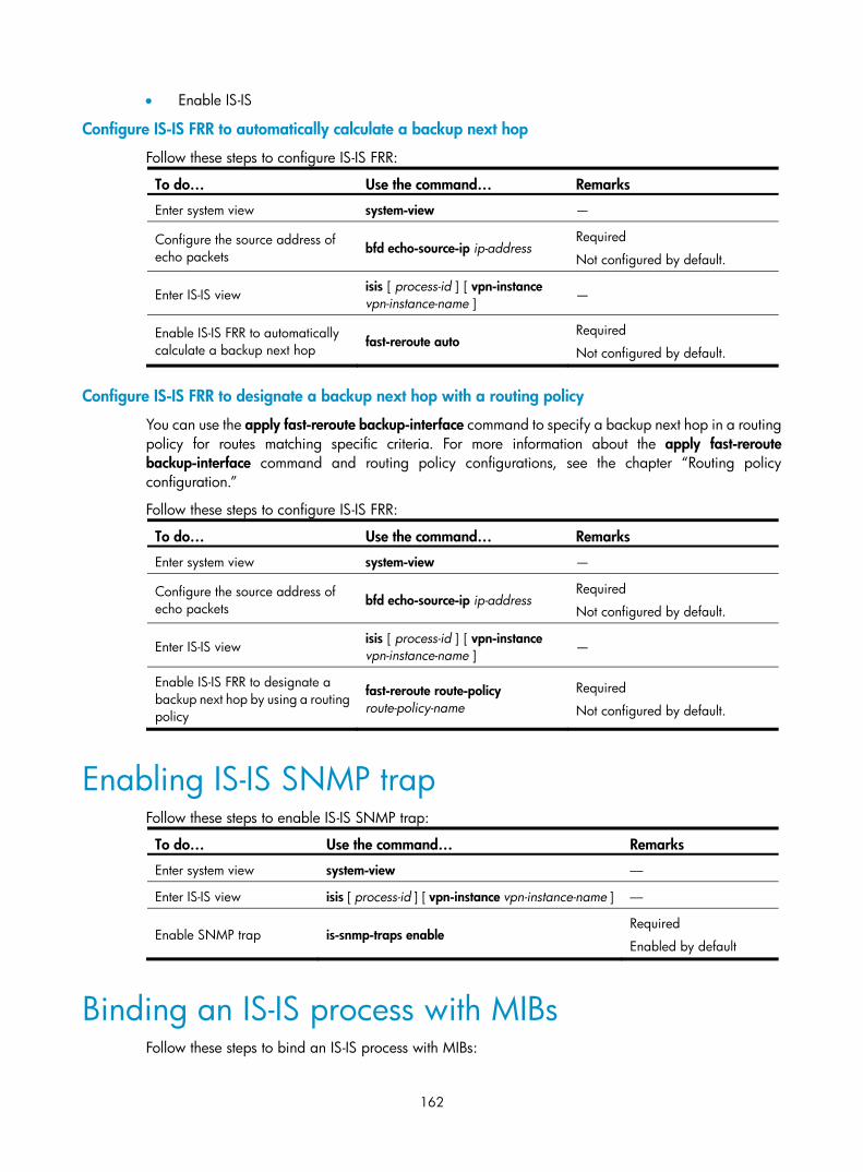
162
• Enable IS-IS
Configure IS-IS FRR to automatically calculate a backup next hop
Follow these steps to configure IS-IS FRR:
To do… Use the command… Remarks
Enter system view system-view —
Configure the source address of echo packets
bfd echo-source-ip ip-address Required
Not configured by default.
Enter IS-IS view isis [ process-id ] [ vpn-instance vpn-instance-name ]
—
Enable IS-IS FRR to automatically calculate a backup next hop fast-reroute auto
Required
Not configured by default.
Configure IS-IS FRR to designate a backup next hop with a routing policy
You can use the apply fast-reroute backup-interface command to specify a backup next hop in a routing policy for routes matching specific criteria. For more information about the apply fast-reroute backup-interface command and routing policy configurations, see the chapter “Routing policy configuration.”
Follow these steps to configure IS-IS FRR:
To do… Use the command… Remarks
Enter system view system-view —
Configure the source address of echo packets bfd echo-source-ip ip-address
Required
Not configured by default.
Enter IS-IS view isis [ process-id ] [ vpn-instance vpn-instance-name ]
—
Enable IS-IS FRR to designate a backup next hop by using a routing policy
fast-reroute route-policy route-policy-name
Required
Not configured by default.
Enabling IS-IS SNMP trap Follow these steps to enable IS-IS SNMP trap:
To do… Use the command… Remarks
Enter system view system-view ––
Enter IS-IS view isis [ process-id ] [ vpn-instance vpn-instance-name ] ––
Enable SNMP trap is-snmp-traps enable Required
Enabled by default
Binding an IS-IS process with MIBs Follow these steps to bind an IS-IS process with MIBs:
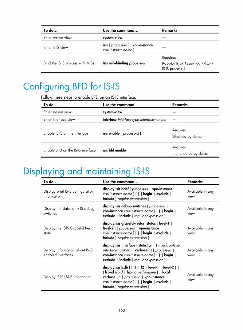
163
To do… Use the command… Remarks
Enter system view system-view —
Enter IS-IS view isis [ process-id ] [ vpn-instance vpn-instance-name ]
—
Bind the IS-IS process with MIBs isis mib-binding process-id Required
By default, MIBs are bound with IS-IS process 1.
Configuring BFD for IS-IS Follow these steps to enable BFD on an IS-IS interface:
To do… Use the command… Remarks
Enter system view system-view —
Enter interface view interface interface-type interface-number —
Enable IS-IS on the interface isis enable [ process-id ] Required
Disabled by default
Enable BFD on the IS-IS interface isis bfd enable Required
Not enabled by default
Displaying and maintaining IS-IS To do… Use the command… Remarks
Display brief IS-IS configuration information
display isis brief [ process-id | vpn-instance vpn-instance-name ] [ | { begin | exclude | include } regular-expression ]
Available in any view
Display the status of IS-IS debug switches
display isis debug-switches { process-id | vpn-instance vpn-instance-name } [ | { begin | exclude | include } regular-expression ]
Available in any view
Display the IS-IS Graceful Restart state
display isis graceful-restart status [ level-1 | level-2 ] [ process-id | vpn-instance vpn-instance-name ] [ | { begin | exclude | include } regular-expression ]
Available in any view
Display information about IS-IS enabled interfaces
display isis interface [ statistics | [ interface-type interface-number ] [ verbose ] ] [ process-id | vpn-instance vpn-instance-name ] [ | { begin | exclude | include } regular-expression ]
Available in any view
Display IS-IS LSDB information
display isis lsdb [ [ l1 | l2 | level-1 | level-2 ] | [ lsp-id lspid | lsp-name lspname ] | local | verbose ] * [ process-id | vpn-instance vpn-instance-name ] [ | { begin | exclude | include } regular-expression ]
Available in any view

164
To do… Use the command… Remarks
Display the host-name-to-system-ID mapping table
display isis name-table [ process-id | vpn-instance vpn-instance-name ] [ | { begin | exclude | include } regular-expression ]
Available in any view
Display IS-IS neighbor information display isis peer [ statistics | verbose ] [ process-id | vpn-instance vpn-instance-name ] [ | { begin | exclude | include } regular-expression ]
Available in any view
Display IS-IS IPv4 routing information
display isis route [ ipv4 ] [ [ level-1 | level-2 ] | verbose ] * [ process-id | vpn-instance vpn-instance-name ] [ | { begin | exclude | include } regular-expression ]
Available in any view
Display IS-IS SPF calculation log information
display isis spf-log [ process-id | vpn-instance vpn-instance-name ] [ | { begin | exclude | include } regular-expression ]
Available in any view
Display IS-IS statistics display isis statistics [ level-1 | level-1-2 | level-2 ] [ process-id | vpn-instance vpn-instance-name ] [ | { begin | exclude | include } regular-expression ]
Available in any view
Clear IS-IS process data structure information
reset isis all [ process-id | vpn-instance vpn-instance-name ]
Available in user view
Clear the data structure information of an IS-IS neighbor
reset isis peer system-id [ process-id | vpn-instance vpn-instance-name ]
Available in user view
IS-IS configuration examples
IS-IS basic configuration Network requirements
As shown in Figure 63, Switch A, B, C, and D reside in an IS-IS AS. Switch A and B are Level-1 switches, Switch D is a Level-2 switch, and Switch C is a Level-1-2 switch. Switch A, B, and C are in Area 10, and Switch D is in Area 20.
Figure 63 Network diagram for IS-IS basic configuration

165
Configuration procedure
1. Configure IP addresses for interfaces. (Details not shown)
2. Configure IS-IS.
# Configure Switch A. <SwitchA> system-view
[SwitchA] isis 1
[SwitchA-isis-1] is-level level-1
[SwitchA-isis-1] network-entity 10.0000.0000.0001.00
[SwitchA-isis-1] quit
[SwitchA] interface vlan-interface 100
[SwitchA-Vlan-interface100] isis enable 1
[SwitchA-Vlan-interface100] quit
# Configure Switch B. <SwitchB> system-view
[SwitchB] isis 1
[SwitchB-isis-1] is-level level-1
[SwitchB-isis-1] network-entity 10.0000.0000.0002.00
[SwitchB-isis-1] quit
[SwitchB] interface vlan-interface 200
[SwitchB-Vlan-interface200] isis enable 1
[SwitchB-Vlan-interface200] quit
# Configure Switch C. <SwitchC> system-view
[SwitchC] isis 1
[SwitchC-isis-1] network-entity 10.0000.0000.0003.00
[SwitchC-isis-1] quit
[SwitchC] interface vlan-interface 100
[SwitchC-Vlan-interface100] isis enable 1
[SwitchC-Vlan-interface100] quit
[SwitchC] interface vlan-interface 200
[SwitchC-Vlan-interface200] isis enable 1
[SwitchC-Vlan-interface200] quit
[SwitchC] interface vlan-interface 300
[SwitchC-Vlan-interface300] isis enable 1
[SwitchC-Vlan-interface300] quit
# Configure Switch D. <SwitchD> system-view
[SwitchD] isis 1
[SwitchD-isis-1] is-level level-2
[SwitchD-isis-1] network-entity 20.0000.0000.0004.00
[SwitchD-isis-1] quit
[SwitchD] interface vlan-interface 100
[SwitchD-Vlan-interface100] isis enable 1
[SwitchD-Vlan-interface100] quit
[SwitchD] interface vlan-interface 300
[SwitchD-Vlan-interface300] isis enable 1

166
[SwitchD-Vlan-interface300] quit
3. Verify the configuration.
# Display the IS-IS LSDB of each switch to check the LSP integrity. [SwitchA] display isis lsdb
Database information for ISIS(1)
--------------------------------
Level-1 Link State Database
LSPID Seq Num Checksum Holdtime Length ATT/P/OL
--------------------------------------------------------------------------
0000.0000.0001.00-00* 0x00000004 0xdf5e 1096 68 0/0/0
0000.0000.0002.00-00 0x00000004 0xee4d 1102 68 0/0/0
0000.0000.0002.01-00 0x00000001 0xdaaf 1102 55 0/0/0
0000.0000.0003.00-00 0x00000009 0xcaa3 1161 111 1/0/0
0000.0000.0003.01-00 0x00000001 0xadda 1112 55 0/0/0
*-Self LSP, +-Self LSP(Extended), ATT-Attached, P-Partition, OL-Overload
[SwitchB] display isis lsdb
Database information for ISIS(1)
--------------------------------
Level-1 Link State Database
LSPID Seq Num Checksum Holdtime Length ATT/P/OL
--------------------------------------------------------------------------
0000.0000.0001.00-00 0x00000006 0xdb60 988 68 0/0/0
0000.0000.0002.00-00* 0x00000008 0xe651 1189 68 0/0/0
0000.0000.0002.01-00* 0x00000005 0xd2b3 1188 55 0/0/0
0000.0000.0003.00-00 0x00000014 0x194a 1190 111 1/0/0
0000.0000.0003.01-00 0x00000002 0xabdb 995 55 0/0/0
*-Self LSP, +-Self LSP(Extended), ATT-Attached, P-Partition, OL-Overload
[SwitchC] display isis lsdb
Database information for ISIS(1)
--------------------------------
Level-1 Link State Database
LSPID Seq Num Checksum Holdtime Length ATT/P/OL
--------------------------------------------------------------------------
0000.0000.0001.00-00 0x00000006 0xdb60 847 68 0/0/0
0000.0000.0002.00-00 0x00000008 0xe651 1053 68 0/0/0
0000.0000.0002.01-00 0x00000005 0xd2b3 1052 55 0/0/0
0000.0000.0003.00-00* 0x00000014 0x194a 1051 111 1/0/0

167
0000.0000.0003.01-00* 0x00000002 0xabdb 854 55 0/0/0
*-Self LSP, +-Self LSP(Extended), ATT-Attached, P-Partition, OL-Overload
Level-2 Link State Database
LSPID Seq Num Checksum Holdtime Length ATT/P/OL
--------------------------------------------------------------------------
0000.0000.0003.00-00* 0x00000012 0xc93c 842 100 0/0/0
0000.0000.0004.00-00 0x00000026 0x331 1173 84 0/0/0
0000.0000.0004.01-00 0x00000001 0xee95 668 55 0/0/0
*-Self LSP, +-Self LSP(Extended), ATT-Attached, P-Partition, OL-Overload
[SwitchD] display isis lsdb
Database information for ISIS(1)
--------------------------------
Level-2 Link State Database
LSPID Seq Num Checksum Holdtime Length ATT/P/OL
-------------------------------------------------------------------------------
0000.0000.0003.00-00 0x00000013 0xc73d 1003 100 0/0/0
0000.0000.0004.00-00* 0x0000003c 0xd647 1194 84 0/0/0
0000.0000.0004.01-00* 0x00000002 0xec96 1007 55 0/0/0
*-Self LSP, +-Self LSP(Extended), ATT-Attached, P-Partition, OL-Overload
# Display the IS-IS routing information of each switch. Level-1 switches must have a default route with the next hop being the Level-1-2 switch. The Level-2 switch must have both routing information of Level-1 and Level-2. [SwitchA] display isis route
Route information for ISIS(1)
-----------------------------
ISIS(1) IPv4 Level-1 Forwarding Table
-------------------------------------
IPV4 Destination IntCost ExtCost ExitInterface NextHop Flags
--------------------------------------------------------------------------
10.1.1.0/24 10 NULL Vlan100 Direct D/L/-
10.1.2.0/24 20 NULL Vlan100 10.1.1.1 R/-/-
192.168.0.0/24 20 NULL Vlan100 10.1.1.1 R/-/-
0.0.0.0/0 10 NULL Vlan100 10.1.1.1 R/-/-
Flags: D-Direct, R-Added to RM, L-Advertised in LSPs, U-Up/Down Bit Set
[SwitchC] display isis route

168
Route information for ISIS(1)
-----------------------------
ISIS(1) IPv4 Level-1 Forwarding Table
-------------------------------------
IPV4 Destination IntCost ExtCost ExitInterface NextHop Flags
--------------------------------------------------------------------------
192.168.0.0/24 10 NULL Vlan300 Direct D/L/-
10.1.1.0/24 10 NULL Vlan100 Direct D/L/-
10.1.2.0/24 10 NULL Vlan200 Direct D/L/-
Flags: D-Direct, R-Added to RM, L-Advertised in LSPs, U-Up/Down Bit Set
ISIS(1) IPv4 Level-2 Forwarding Table
-------------------------------------
IPV4 Destination IntCost ExtCost ExitInterface NextHop Flags
--------------------------------------------------------------------------
192.168.0.0/24 10 NULL Vlan300 Direct D/L/-
10.1.1.0/24 10 NULL Vlan100 Direct D/L/-
10.1.2.0/24 10 NULL Vlan200 Direct D/L/-
172.16.0.0/16 20 NULL Vlan300 192.168.0.2 R/-/-
Flags: D-Direct, R-Added to RM, L-Advertised in LSPs, U-Up/Down Bit Set
[SwitchD] display isis route
Route information for ISIS(1)
-----------------------------
ISIS(1) IPv4 Level-2 Forwarding Table
-------------------------------------
IPV4 Destination IntCost ExtCost ExitInterface NextHop Flags
--------------------------------------------------------------------------
192.168.0.0/24 10 NULL Vlan300 Direct D/L/-
10.1.1.0/24 20 NULL Vlan300 192.168.0.1 R/-/-
10.1.2.0/24 20 NULL Vlan300 192.168.0.1 R/-/-
172.16.0.0/16 10 NULL Vlan100 Direct D/L/-
Flags: D-Direct, R-Added to RM, L-Advertised in LSPs, U-Up/Down Bit Set

169
DIS election configuration Network requirements
As shown in Figure 64, Switch A, B, C, and D reside in IS-IS area 10 on a broadcast network (Ethernet). Switch A and Switch B are Level-1-2 switches, Switch C is a Level-1 switch, and Switch D is a Level-2 switch.
Change the DIS priority of Switch A to make it elected as the Level-1-2 DIS router.
Figure 64 Network diagram for DIS selection
Configuration procedure
1. Configure an IP address for each interface. (Details not shown)
2. Enable IS-IS.
# Configure Switch A. <SwitchA> system-view
[SwitchA] isis 1
[SwitchA-isis-1] network-entity 10.0000.0000.0001.00
[SwitchA-isis-1] quit
[SwitchA] interface vlan-interface 100
[SwitchA-Vlan-interface100] isis enable 1
[SwitchA-Vlan-interface100] quit
# Configure Switch B. <SwitchB> system-view
[SwitchB] isis 1
[SwitchB-isis-1] network-entity 10.0000.0000.0002.00
[SwitchB-isis-1] quit
[SwitchB] interface vlan-interface 100
[SwitchB-Vlan-interface100] isis enable 1
[SwitchB-Vlan-interface100] quit
# Configure Switch C. <SwitchC> system-view
[SwitchC] isis 1
[SwitchC-isis-1] network-entity 10.0000.0000.0003.00
[SwitchC-isis-1] is-level level-1
[SwitchC-isis-1] quit

170
[SwitchC] interface vlan-interface 100
[SwitchC-Vlan-interface100] isis enable 1
[SwitchC-Vlan-interface100] quit
# Configure Switch D. <SwitchD> system-view
[SwitchD] isis 1
[SwitchD-isis-1] network-entity 10.0000.0000.0004.00
[SwitchD-isis-1] is-level level-2
[SwitchD-isis-1] quit
[SwitchD] interface vlan-interface 100
[SwitchD-Vlan-interface100] isis enable 1
[SwitchD-Vlan-interface100] quit
# Display information about IS-IS neighbors of Switch A. [SwitchA] display isis peer
Peer information for ISIS(1)
----------------------------
System Id: 0000.0000.0002
Interface: Vlan-interface100 Circuit Id: 0000.0000.0003.01
State: Up HoldTime: 21s Type: L1(L1L2) PRI: 64
System Id: 0000.0000.0003
Interface: Vlan-interface100 Circuit Id: 0000.0000.0003.01
State: Up HoldTime: 27s Type: L1 PRI: 64
System Id: 0000.0000.0002
Interface: Vlan-interface100 Circuit Id: 0000.0000.0004.01
State: Up HoldTime: 28s Type: L2(L1L2) PRI: 64
System Id: 0000.0000.0004
Interface: Vlan-interface100 Circuit Id: 0000.0000.0004.01
State: Up HoldTime: 30s Type: L2 PRI: 64
# Display information about IS-IS interfaces of Switch A. [SwitchA] display isis interface
Interface information for ISIS(1)
---------------------------------
Interface: Vlan-interface100
Id IPV4.State IPV6.State MTU Type DIS
001 Up Down 1497 L1/L2 No/No
# Display information about IS-IS interfaces of Switch C. [SwitchC] display isis interface
Interface information for ISIS(1)
---------------------------------
Interface: Vlan-interface100

171
Id IPV4.State IPV6.State MTU Type DIS
001 Up Down 1497 L1/L2 Yes/No
# Display information about IS-IS interfaces of Switch D. [SwitchD] display isis interface
Interface information for ISIS(1)
---------------------------------
Interface: Vlan-interface100
Id IPV4.State IPV6.State MTU Type DIS
001 Up Down 1497 L1/L2 No/Yes
NOTE:
By using the default DIS priority, Switch C is the Level-1 DIS, and Switch D is the Level-2 DIS. The pseudonodes of Level-1 and Level-2 are 0000.0000.0003.01 and 0000.0000.0004.01, respectively.
3. Configure the DIS priority of Switch A. [SwitchA] interface vlan-interface 100
[SwitchA-Vlan-interface100] isis dis-priority 100
[SwitchA-Vlan-interface100] quit
# Display IS-IS neighbors of Switch A. [SwitchA] display isis peer
Peer information for ISIS(1)
----------------------------
System Id: 0000.0000.0002
Interface: Vlan-interface100 Circuit Id: 0000.0000.0001.01
State: Up HoldTime: 21s Type: L1(L1L2) PRI: 64
System Id: 0000.0000.0003
Interface: Vlan-interface100 Circuit Id: 0000.0000.0001.01
State: Up HoldTime: 27s Type: L1 PRI: 64
System Id: 0000.0000.0002
Interface: Vlan-interface100 Circuit Id: 0000.0000.0001.01
State: Up HoldTime: 28s Type: L2(L1L2) PRI: 64
System Id: 0000.0000.0004
Interface: Vlan-interface100 Circuit Id: 0000.0000.0001.01
State: Up HoldTime: 30s Type: L2 PRI: 64
# Display information about IS-IS interfaces of Switch A. [SwitchA] display isis interface
Interface information for ISIS(1)
---------------------------------
Interface: Vlan-interface100

172
Id IPV4.State IPV6.State MTU Type DIS
001 Up Down 1497 L1/L2 Yes/Yes
NOTE:
After the DIS priority configuration, Switch A becomes the Level-1-2 DIS, and the pseudonode is 0000.0000.0001.01.
# Display information about IS-IS neighbors and interfaces of Switch C. [SwitchC] display isis peer
Peer information for ISIS(1)
----------------------------
System Id: 0000.0000.0002
Interface: Vlan-interface100 Circuit Id: 0000.0000.0001.01
State: Up HoldTime: 25s Type: L1 PRI: 64
System Id: 0000.0000.0001
Interface: Vlan-interface100 Circuit Id: 0000.0000.0001.01
State: Up HoldTime: 7s Type: L1 PRI: 100
[SwitchC] display isis interface
Interface information for ISIS(1)
---------------------------------
Interface: Vlan-interface100
Id IPV4.State IPV6.State MTU Type DIS
001 Up Down 1497 L1/L2 No/No
# Display information about IS-IS neighbors and interfaces of Switch D. [SwitchD] display isis peer
Peer information for ISIS(1)
----------------------------
System Id: 0000.0000.0001
Interface: Vlan-interface100 Circuit Id: 0000.0000.0001.01
State: Up HoldTime: 9s Type: L2 PRI: 100
System Id: 0000.0000.0002
Interface: Vlan-interface100 Circuit Id: 0000.0000.0001.01
State: Up HoldTime: 28s Type: L2 PRI: 64
[SwitchD] display isis interface
Interface information for ISIS(1)
---------------------------------
Interface: Vlan-interface100
Id IPV4.State IPV6.State MTU Type DIS
001 Up Down 1497 L1/L2 No/No

173
Configuring IS-IS route redistribution Network requirements
As shown in Figure 65, Switch A, Switch B, Switch C, and Switch D reside in the same AS. They use IS-IS to interconnect. Switch A and Switch B are Level-1 routers, Switch D is a Level-2 router, and Switch C is a Level-1-2 router.
Redistribute RIP routes into IS-IS on Switch D.
Figure 65 Network diagram for IS-IS route redistribution
Configuration procedure
1. Configure IP addresses for interfaces. (Details not shown)
2. Configure IS-IS basic functions.
# Configure Switch A. <SwitchA> system-view
[SwitchA] isis 1
[SwitchA-isis-1] is-level level-1
[SwitchA-isis-1] network-entity 10.0000.0000.0001.00
[SwitchA-isis-1] quit
[SwitchA] interface vlan-interface 100
[SwitchA-Vlan-interface100] isis enable 1
[SwitchA-Vlan-interface100] quit
# Configure Switch B. <SwitchB> system-view
[SwitchB] isis 1
[SwitchB-isis-1] is-level level-1
[SwitchB-isis-1] network-entity 10.0000.0000.0002.00
[SwitchB-isis-1] quit
[SwitchB] interface vlan-interface 200
[SwitchB-Vlan-interface200] isis enable 1
[SwitchB-Vlan-interface200] quit
# Configure Switch C. <SwitchC> system-view
[SwitchC] isis 1

174
[SwitchC-isis-1] network-entity 10.0000.0000.0003.00
[SwitchC-isis-1] quit
[SwitchC] interface vlan-interface 200
[SwitchC-Vlan-interface200] isis enable 1
[SwitchC-Vlan-interface200] quit
[SwitchC] interface vlan-interface 100
[SwitchC-Vlan-interface100] isis enable 1
[SwitchC-Vlan-interface100] quit
[SwitchC] interface vlan-interface 300
[SwitchC-Vlan-interface300] isis enable 1
[SwitchC-Vlan-interface300] quit
# Configure Switch D. <SwitchD> system-view
[SwitchD] isis 1
[SwitchD-isis-1] is-level level-2
[SwitchD-isis-1] network-entity 20.0000.0000.0004.00
[SwitchD-isis-1] quit
[SwitchD] interface interface vlan-interface 300
[SwitchD-Vlan-interface300] isis enable 1
[SwitchD-Vlan-interface300] quit
# Display IS-IS routing information on each switch. [SwitchA] display isis route
Route information for ISIS(1)
-----------------------------
ISIS(1) IPv4 Level-1 Forwarding Table
-------------------------------------
IPV4 Destination IntCost ExtCost ExitInterface NextHop Flags
--------------------------------------------------------------------------
10.1.1.0/24 10 NULL VLAN100 Direct D/L/-
10.1.2.0/24 20 NULL VLAN100 10.1.1.1 R/-/-
192.168.0.0/24 20 NULL VLAN100 10.1.1.1 R/-/-
0.0.0.0/0 10 NULL VLAN100 10.1.1.1 R/-/-
Flags: D-Direct, R-Added to RM, L-Advertised in LSPs, U-Up/Down Bit Set
[SwitchC] display isis route
Route information for ISIS(1)
-----------------------------
ISIS(1) IPv4 Level-1 Forwarding Table
-------------------------------------
IPV4 Destination IntCost ExtCost ExitInterface NextHop Flags
--------------------------------------------------------------------------

175
10.1.1.0/24 10 NULL VLAN100 Direct D/L/-
10.1.2.0/24 10 NULL VLAN200 Direct D/L/-
192.168.0.0/24 10 NULL VLAN300 Direct D/L/-
Flags: D-Direct, R-Added to RM, L-Advertised in LSPs, U-Up/Down Bit Set
ISIS(1) IPv4 Level-2 Forwarding Table
-------------------------------------
IPV4 Destination IntCost ExtCost ExitInterface NextHop Flags
--------------------------------------------------------------------------
10.1.1.0/24 10 NULL VLAN100 Direct D/L/-
10.1.2.0/24 10 NULL VLAN200 Direct D/L/-
192.168.0.0/24 10 NULL VLAN300 Direct D/L/-
Flags: D-Direct, R-Added to RM, L-Advertised in LSPs, U-Up/Down Bit Set
[SwitchD] display isis route
Route information for ISIS(1)
-----------------------------
ISIS(1) IPv4 Level-2 Forwarding Table
-------------------------------------
IPV4 Destination IntCost ExtCost ExitInterface NextHop Flags
--------------------------------------------------------------------------
192.168.0.0/24 10 NULL VLAN300 Direct D/L/-
10.1.1.0/24 20 NULL VLAN300 192.168.0.1 R/-/-
10.1.2.0/24 20 NULL VLAN300 192.168.0.1 R/-/-
Flags: D-Direct, R-Added to RM, L-Advertised in LSPs, U-Up/Down Bit Set
3. Configure RIPv2 on Switch D and Switch E, and configure route redistribution from RIP to IS-IS on Switch D.
# Configure RIPv2 on Switch D. [SwitchD] rip 1
[SwitchD-rip-1] network 10.0.0.0
[SwitchD-rip-1] version 2
[SwitchD-rip-1] undo summary
# Configure RIPv2 on Switch E. [SwitchE] rip 1
[SwitchE-rip-1] network 10.0.0.0
[SwitchE-rip-1] version 2
[SwitchE-rip-1] undo summary
# Configure route redistribution from RIP to IS-IS on Switch D. [SwitchD-rip-1] quit

176
[SwitchD] isis 1
[SwitchD–isis-1] import-route rip level-2
# Display IS-IS routing information on Switch C. [SwitchC] display isis route
Route information for ISIS(1)
-----------------------------
ISIS(1) IPv4 Level-1 Forwarding Table
-------------------------------------
IPV4 Destination IntCost ExtCost ExitInterface NextHop Flags
--------------------------------------------------------------------------
10.1.1.0/24 10 NULL VLAN100 Direct D/L/-
10.1.2.0/24 10 NULL VLAN200 Direct D/L/-
192.168.0.0/24 10 NULL VLAN300 Direct D/L/-
Flags: D-Direct, R-Added to RM, L-Advertised in LSPs, U-Up/Down Bit Set
ISIS(1) IPv4 Level-2 Forwarding Table
-------------------------------------
IPV4 Destination IntCost ExtCost ExitInterface NextHop Flags
--------------------------------------------------------------------------
10.1.1.0/24 10 NULL VLAN100 Direct D/L/-
10.1.2.0/24 10 NULL VLAN200 Direct D/L/-
192.168.0.0/24 10 NULL VLAN300 Direct D/L/-
10.1.4.0/24 10 NULL VLAN300 192.168.0.2 R/L/-
10.1.5.0/24 20 NULL VLAN300 192.168.0.2 R/L/-
10.1.6.0/24 20 NULL VLAN300 192.168.0.2 R/L/-
Flags: D-Direct, R-Added to RM, L-Advertised in LSPs, U-Up/Down Bit Set
IS-IS Graceful Restart configuration example Network requirements
Switch A, Switch B, and Switch C belong to the same IS-IS routing domain, as illustrated in Figure 66.

177
Figure 66 Network diagram for IS-IS GR configuration
Vlan-int10010.0.0.1/24
Vlan-int10010.0.0.3/24
Vlan-int10010.0.0.2/24
GR helper GR helper
GR restarter
Switch A
Switch CSwitch B
Configuration procedure
1. Configure IP addresses of the interfaces on each switch and configure IS-IS.
Follow Figure 66 to configure the IP address and subnet mask of each interface. (Details not shown)
Configure IS-IS on the switches, ensuring that Switch A, Switch B and Switch C can communicate with each other at layer 3 and dynamic route update can be implemented among them with IS-IS. (Details not shown)
2. Configure IS-IS Graceful Restart.
# Enable IS-IS Graceful Restart on Switch A and configure the Graceful Restart Interval. <SwitchA> system-view
[SwitchA] isis 1
[SwitchA-isis-1] graceful-restart
[SwitchA-isis-1] graceful-restart interval 150
[SwitchA-isis-1] return
Configurations for Switch B and Switch C are similar; therefore, details are not shown.
3. Verify the configuration.
After Router A establishes adjacencies with Router B and Router C, they begin to exchange routing information. Restart IS-IS on Router A, which enters the restart state and sends connection requests to its neighbors through the Graceful Restart mechanism to synchronize the LSDB. Using the display isis graceful-restart status command can display the IS-IS GR status on Router A.
# Restart the IS-IS process on Switch A. <SwitchA> reset isis all 1
Warning : Reset ISIS process? [Y/N]:y
# Check the Graceful Restart status of IS-IS on Switch A. <SwitchA> display isis graceful-restart status
Restart information for IS-IS(1)
--------------------------------------------------------------------
IS-IS(1) Level-1 Restart Status
Restart Interval: 150
SA Bit Supported
Total Number of Interfaces = 1
Restart Status: RESTARTING
Number of LSPs Awaited: 3
T3 Timer Status:
Remaining Time: 140

178
T2 Timer Status:
Remaining Time: 59
IS-IS(1) Level-2 Restart Status
Restart Interval: 150
SA Bit Supported
Total Number of Interfaces = 1
Restart Status: RESTARTING
Number of LSPs Awaited: 3
T3 Timer Status:
Remaining Time: 140
T2 Timer Status:
Remaining Time: 59
IS-IS NSR configuration example Network requirements
Switch S, Switch A, and Switch B belong to the same IS-IS routing domain as illustrated in Figure 67. Switch S is an IRF fabric, which is connected to Switch A and Switch B over aggregated links. Enable IS-IS NSR on Switch S to ensure correct routing when a master/slave switchover occurs on Switch S.
Figure 67 Network diagram for IS-IS NSR configuration
Configuration procedure
1. Configure IP addresses for the interfaces on each switch and configure IS-IS.
Follow Figure 67 to configure the IP address and subnet mask of each interface on the switches. (Details not shown)
Configure IS-IS on the switches, ensuring that Switch S, Switch A, and Switch B can communicate with each other at Layer 3 and dynamic route update can be implemented among them with IS-IS. (Details not shown)
2. Configure IS-IS NSR.
# Enable IS-IS NSR on Switch S. <SwitchS> system-view
[SwitchS] isis 1
[SwitchS-isis-1] non-stop-routing
[SwitchS-isis-1] non-stop-routing interval 30
[SwitchS-isis-1] return
3. Verify the configuration.
After Switch S establishes neighbor relationships with Switch A and Switch B, they start to exchange routing information. After network convergence, perform a master/slave switchover on Switch S. During the switchover period, use the display isis peer command to check the neighbor relationship between Switch A and Switch S and between Switch B and Switch S; use the display isis route command to check

179
if routes from Switch A to the loopback interface on Switch B and from Switch B to the loopback interface on Switch A exist.
# When a master/slave switchover occurs on Switch S, display IS-IS neighbors and routes on Switch A. <SwitchA> display isis peer
Peer information for ISIS(1)
----------------------------
System Id: 0000.0000.0001
Interface: vlan100 Circuit Id: 0000.0000.0001.01
State: Up HoldTime: 25s Type: L1(L1L2) PRI: 64
System Id: 0000.0000.0001
Interface: vlan100 Circuit Id: 0000.0000.0001.01
State: Up HoldTime: 27s Type: L2(L1L2) PRI: 64
<SwitchA> display isis route
Route information for ISIS(1)
-----------------------------
ISIS(1) IPv4 Level-1 Forwarding Table
-------------------------------------
IPV4 Destination IntCost ExtCost ExitInterface NextHop Flags
--------------------------------------------------------------------------
12.12.12.0/24 10 NULL vlan100 Direct D/L/-
22.22.22.22/32 10 NULL Loop0 Direct D/-/-
14.14.14.0/32 10 NULL vlan100 12.12.12.2 R/L/-
44.44.44.44/32 10 NULL vlan100 12.12.12.2 R/L/-
Flags: D-Direct, R-Added to RM, L-Advertised in LSPs, U-Up/Down Bit Set
ISIS(1) IPv4 Level-2 Forwarding Table
-------------------------------------
IPV4 Destination IntCost ExtCost ExitInterface NextHop Flags
--------------------------------------------------------------------------
12.12.12.0/24 10 NULL vlan100 Direct D/L/-
22.22.22.22/32 10 NULL Loop0 Direct D/-/-
14.14.14.0/32 10 NULL
44.44.44.44/32 10 NULL
Flags: D-Direct, R-Added to RM, L-Advertised in LSPs, U-Up/Down Bit Set
# Display IS-IS neighbors and routes on Switch B. <SwitchB> display isis peer
Peer information for ISIS(1)
----------------------------
System Id: 0000.0000.0001

180
Interface: vlan200 Circuit Id: 0000.0000.0001.01
State: Up HoldTime: 25s Type: L1(L1L2) PRI: 64
System Id: 0000.0000.0001
Interface: vlan200 Circuit Id: 0000.0000.0001.01
State: Up HoldTime: 27s Type: L2(L1L2) PRI: 64
<SwitchB> display isis route
Route information for ISIS(1)
-----------------------------
ISIS(1) IPv4 Level-1 Forwarding Table
-------------------------------------
IPV4 Destination IntCost ExtCost ExitInterface NextHop Flags
--------------------------------------------------------------------------
14.14.14.0/24 10 NULL vlan200 Direct D/L/-
44.44.44.44/32 10 NULL Loop0 Direct D/-/-
12.12.12.0/32 10 NULL vlan200 14.14.14.4 R/L/-
22.22.22.22/32 10 NULL vlan200 14.14.14.4 R/L/-
Flags: D-Direct, R-Added to RM, L-Advertised in LSPs, U-Up/Down Bit Set
ISIS(1) IPv4 Level-2 Forwarding Table
-------------------------------------
IPV4 Destination IntCost ExtCost ExitInterface NextHop Flags
--------------------------------------------------------------------------
14.14.14.0/24 10 NULL vlan200 Direct D/L/-
44.44.44.44/32 10 NULL Loop0 Direct D/-/-
12.12.12.0/32 10 NULL
22.22.22.22/32 10 NULL
Flags: D-Direct, R-Added to RM, L-Advertised in LSPs, U-Up/Down Bit Set
The output information shows that the neighbor relationships and routing information on Switch A and Switch B have not changed. The neighbors cannot sense the switchover on Switch S.
IS-IS FRR configuration example Network requirements
Switch S, Switch A, and Switch D belong to the same IS-IS routing domain as illustrated in Figure 68. Configure IS-IS FRR so that when the link between Switch S and Switch D fails, traffic can be switched to Link B immediately.

181
Figure 68 Network diagram for IS-IS FRR configuration
Switch S Switch D
Switch A
Loop 01.1.1.1/32
Vlan-int100
12.12.12.1/24
Vlan-int20013.13.13.1/24
Vlan-int20013.13.13.2/24
Vlan-int100
12.12.12.2/24Vlan-int101
24.24.24.2/24 Vlan-int101
24.24.24.4/24Loop 0
4.4.4.4/32
Link A
Link B
Configuration procedure
1. Configure IP addresses for the interfaces on each switch and configure IS-IS.
Follow Figure 68 to configure the IP address and subnet mask of each interface on the switches. (Details not shown)
Configure IS-IS on the switches, ensuring that Switch A, Switch D, and Switch S can communicate with each other at Layer 3. (Details not shown)
2. Configure IS-IS FRR.
You can enable IS-IS FRR to either automatically calculate a backup next hop, or to designate a backup next hop by using a referenced routing policy.
Method I: Enable IS-IS FRR to automatically calculate a backup next hop.
# Configure Switch S. <SwitchS> system-view
[SwitchS] bfd echo-source-ip 1.1.1.1
[SwitchS] isis 1
[SwitchS-isis-1] fast-reroute auto
[SwitchS-isis-1] quit
# Configure Switch D. <SwitchD> system-view
[SwitchD] bfd echo-source-ip 4.4.4.4
[SwitchD] isis 1
[SwitchD-isis-1] fast-reroute auto
[SwitchD-isis-1] quit
Method II: Enable IS-IS FRR to designate a backup next hop by using a referenced routing policy.
# Configure Switch S. <SwitchS> system-view
[SwitchS] bfd echo-source-ip 1.1.1.1
[SwitchS] ip ip-prefix abc index 10 permit 4.4.4.4 32
[SwitchS] route-policy frr permit node 10
[SwitchS-route-policy] if-match ip-prefix abc
[SwitchS-route-policy] apply fast-reroute backup-interface vlan-interface 100 backup-nexthop 12.12.12.2
[SwitchS-route-policy] quit
[SwitchS] isis 1
[SwitchS-isis-1] fast-reroute route-policy frr
[SwitchS-isis-1] quit
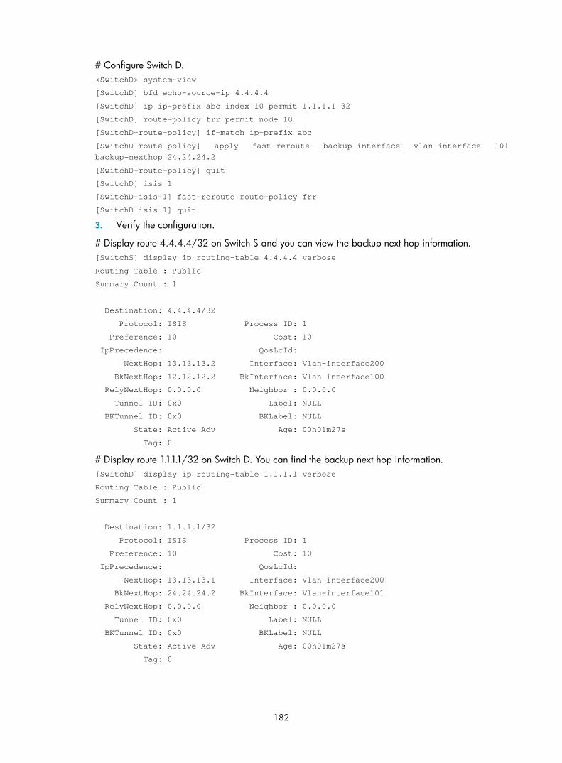
182
# Configure Switch D. <SwitchD> system-view
[SwitchD] bfd echo-source-ip 4.4.4.4
[SwitchD] ip ip-prefix abc index 10 permit 1.1.1.1 32
[SwitchD] route-policy frr permit node 10
[SwitchD-route-policy] if-match ip-prefix abc
[SwitchD-route-policy] apply fast-reroute backup-interface vlan-interface 101 backup-nexthop 24.24.24.2
[SwitchD-route-policy] quit
[SwitchD] isis 1
[SwitchD-isis-1] fast-reroute route-policy frr
[SwitchD-isis-1] quit
3. Verify the configuration.
# Display route 4.4.4.4/32 on Switch S and you can view the backup next hop information. [SwitchS] display ip routing-table 4.4.4.4 verbose
Routing Table : Public
Summary Count : 1
Destination: 4.4.4.4/32
Protocol: ISIS Process ID: 1
Preference: 10 Cost: 10
IpPrecedence: QosLcId:
NextHop: 13.13.13.2 Interface: Vlan-interface200
BkNextHop: 12.12.12.2 BkInterface: Vlan-interface100
RelyNextHop: 0.0.0.0 Neighbor : 0.0.0.0
Tunnel ID: 0x0 Label: NULL
BKTunnel ID: 0x0 BKLabel: NULL
State: Active Adv Age: 00h01m27s
Tag: 0
# Display route 1.1.1.1/32 on Switch D. You can find the backup next hop information. [SwitchD] display ip routing-table 1.1.1.1 verbose
Routing Table : Public
Summary Count : 1
Destination: 1.1.1.1/32
Protocol: ISIS Process ID: 1
Preference: 10 Cost: 10
IpPrecedence: QosLcId:
NextHop: 13.13.13.1 Interface: Vlan-interface200
BkNextHop: 24.24.24.2 BkInterface: Vlan-interface101
RelyNextHop: 0.0.0.0 Neighbor : 0.0.0.0
Tunnel ID: 0x0 Label: NULL
BKTunnel ID: 0x0 BKLabel: NULL
State: Active Adv Age: 00h01m27s
Tag: 0

183
IS-IS authentication configuration example Network requirements
As shown in Figure 69, Switch A, Switch B, Switch C and Switch D reside in the same IS-IS routing domain.
Switch A, Switch B, and Switch C belong to Area 10, and Switch D belongs to Area 20.
Configure relationship authentication between neighbors. Configure area authentication in Area 10 to prevent untrusted routes from entering into the area. Configure routing domain authentication on Switch C and Switch D to prevent untrusted routes from entering the routing domain.
Figure 69 Network diagram for IS-IS authentication configuration
Configuration procedure
1. Configure IP addresses for interfaces. (Details not shown)
2. Configure IS-IS basic functions.
# Configure Switch A. <SwitchA> system-view
[SwitchA] isis 1
[SwitchA-isis-1] network-entity 10.0000.0000.0001.00
[SwitchA-isis-1] quit
[SwitchA] interface vlan-interface 100
[SwitchA-Vlan-interface100] isis enable 1
[SwitchA-Vlan-interface100] quit
# Configure Switch B. <SwitchB> system-view
[SwitchB] isis 1
[SwitchB-isis-1] network-entity 10.0000.0000.0002.00
[SwitchB-isis-1] quit
[SwitchB] interface vlan-interface 200
[SwitchB-Vlan-interface200] isis enable 1
[RouterB--Vlan-interface200] quit
# Configure Switch C. <SwitchC> system-view

184
[SwitchC] isis 1
[SwitchC-isis-1] network-entity 10.0000.0000.0003.00
[SwitchC-isis-1] quit
[SwitchC] interface vlan-interface 200
[SwitchC-Vlan-interface200] isis enable 1
[SwitchC-Vlan-interface200] quit
[SwitchC] interface vlan-interface 300
[SwitchC-Vlan-interface300] isis enable 1
[SwitchC-Vlan-interface300] quit
[SwitchC] interface vlan-interface 300
[SwitchC-Vlan-interface300] isis enable 1
[SwitchC-Vlan-interface300] quit
# Configure Switch D. <SwitchD> system-view
[SwitchD] isis 1
[SwitchD-isis-1] network-entity 20.0000.0000.0001.00
[SwitchD-isis-1] quit
[SwitchD] interface vlan-interface 300
[SwitchD-Vlan-interface300] isis enable 1
[SwitchD-Vlan-interface300] quit
3. Configure neighbor relationship authentication between neighbors.
# Specify the MD5 authentication mode and password eRq on VLAN-interface 100 of Switch A and on VLAN-interface 100 of Switch C. [SwitchA] interface vlan-interface 100
[SwitchA-Vlan-interface100] isis authentication-mode md5 eRg
[SwitchA-Vlan-interface100] quit
[SwitchC] interface vlan-interface 100
[SwitchC-Vlan-interface100] isis authentication-mode md5 eRg
[SwitchC-Vlan-interface100] quit
# Specify the MD5 authentication mode and password t5Hr on VLAN-interface 200 of Switch B and on VLAN-interface 200 of Switch C. [SwitchB] interface vlan-interface 200
[SwitchB-Vlan-interface200] isis authentication-mode md5 t5Hr
[SwitchB-Vlan-interface200] quit
[SwitchC] interface vlan-interface 200
[SwitchC-Vlan-interface200] isis authentication-mode md5 t5Hr
[SwitchC-Vlan-interface200] quit
# Specify the MD5 authentication mode and password hSec on VLAN-interface 300 of Switch D and on VLAN-interface 300 of Switch C. [SwitchC] interface vlan-interface 300
[SwitchC-Vlan-interface300] isis authentication-mode md5 hSec
[SwitchC-Vlan-interface300] quit
[SwitchD] interface vlan-interface 300
[SwitchD-Vlan-interface300] isis authentication-mode md5 hSec
[SwitchD-Vlan-interface300] quit
4. Configure area authentication. Specify the MD5 authentication mode and password 10Sec on Switch A, Switch B, and Switch C.

185
[SwitchA] isis 1
[SwitchA-isis-1] area-authentication-mode md5 10Sec
[SwitchA-isis-1] quit
[SwitchB] isis 1
[SwitchB-isis-1] area-authentication-mode md5 10Sec
[SwitchB-isis-1] quit
[SwitchC] isis 1
[SwitchC-isis-1] area-authentication-mode md5 10Sec
[SwitchC-isis-1] quit
5. Configure routing domain authentication. Specify the MD5 authentication mode and password 1020Sec on Switch C and Switch D.
[SwitchC] isis 1
[SwitchC-isis-1] domain-authentication-mode md5 1020Sec
[SwitchC-isis-1] quit
[SwitchD] isis 1
[SwitchD-isis-1] domain-authentication-mode md5 1020Sec
Configuring BFD for IS-IS Network requirements
• As shown in Figure 70, IS-IS is enabled on Switch A, Switch B and Switch C that are reachable to each other at the network layer.
• After the link over which Switch A and Switch B communicate through the Layer-2 switch fails, BFD can quickly detect the failure and notify IS-IS of the failure. Switch A and Switch B then communicate through Switch C.
Figure 70 Network diagram for BFD configuration on an IS-IS link
Device Interface IP address Device Interface IP address Switch A Vlan-int10 10.1.0.102/24 Switch B Vlan-int10 10.1.0.100/24 Vlan-int11 11.1.1.1/24 Vlan-int13 13.1.1.1/24 Switch C Vlan-int11 11.1.1.2/24 Vlan-int13 13.1.1.2/24
Configuration procedure
1. Configure IP addresses for interfaces (details not shown).
2. Configure IS-IS basic functions.

186
# Configure Switch A. <SwitchA> system-view
[SwitchA] isis
[SwitchA-isis-1] network-entity 10.0000.0000.0001.00
[SwitchA-isis-1] quit
[SwitchA] interface vlan-interface 10
[SwitchA-Vlan-interface10] isis enable
[SwitchA-Vlan-interface10] quit
[SwitchA] interface vlan-interface 11
[SwitchA-Vlan-interface11] isis enable
[SwitchA-Vlan-interface11] quit
# Configure Switch B. <SwitchB> system-view
[SwitchB] isis
[SwitchB-isis-1] network-entity 10.0000.0000.0002.00
[SwitchB-isis-1] quit
[SwitchB] interface vlan-interface 10
[SwitchB-Vlan-interface10] isis enable
[SwitchB-Vlan-interface10] quit
[SwitchB] interface vlan-interface 13
[SwitchB-Vlan-interface13] isis enable
[SwitchB-Vlan-interface13] quit
# Configure Switch C. <SwitchC> system-view
[SwitchC] isis
[SwitchC-isis-1] network-entity 10.0000.0000.0003.00
[SwitchC-isis-1] quit
[SwitchC] interface vlan-interface 11
[SwitchC-Vlan-interface11] isis enable
[SwitchC-Vlan-interface11] quit
[SwitchC] interface vlan-interface 13
[SwitchC-Vlan-interface13] isis enable
[SwitchC-Vlan-interface13] quit
3. Configure BFD parameters.
# Enable BFD on Switch A and configure BFD parameters. [SwitchA] bfd session init-mode active
[SwitchA] interface vlan-interface 10
[SwitchA-Vlan-interface10] isis bfd enable
[SwitchA-Vlan-interface10] bfd min-receive-interval 500
[SwitchA-Vlan-interface10] bfd min-transmit-interval 500
[SwitchA-Vlan-interface10] bfd detect-multiplier 7
# Enable BFD on Switch B and configure BFD parameters. [SwitchB] bfd session init-mode active
[SwitchB] interface vlan-interface 10
[SwitchB-Vlan-interface10] isis bfd enable
[SwitchB-Vlan-interface10] bfd min-receive-interval 500
[SwitchB-Vlan-interface10] bfd min-transmit-interval 500

187
[SwitchB-Vlan-interface10] bfd detect-multiplier 8
[SwitchB-Vlan-interface10] return
4. Verify the configuration.
The following configurations are made on Switch A. Configurations for Switch B are similar. (Details not shown)
# Display the BFD information of Switch A. <SwitchA> display bfd session
Total Session Num: 1 Init Mode: Active
Session Working Under Ctrl Mode:
LD/RD SourceAddr DestAddr State Holdtime Interface
3/1 10.1.0.102 10.1.0.100 Up 1700ms vlan10
# Display route 120.1.1.0/24 on Switch A, and you can see that Switch A and Switch B communicate through the Layer-2 switch. <SwitchA> display ip routing-table 120.1.1.0 verbose
Routing Table : Public
Summary Count : 2
Destination: 120.1.1.0/24
Protocol: ISIS Process ID: 0
Preference: 0 Cost: 2
IpPrecedence: QosLcId:
NextHop: 192.168.0.100 Interface: Vlan-interface10
BkNextHop: 0.0.0.0 BkInterface:
RelyNextHop: 0.0.0.0 Neighbor : 0.0.0.0
Tunnel ID: 0x0 Label: NULL
BKTunnel ID: 0x0 BKLabel: NULL
State: Active Adv Age: 00h58m10s
Tag: 0
Destination: 120.1.1.0/24
Protocol: ISIS Process ID: 1
Preference: 10 Cost: 4
IpPrecedence: QosLcId:
NextHop: 10.1.1.100 Interface: Vlan-interface11
BkNextHop: 0.0.0.0 BkInterface:
RelyNextHop: 0.0.0.0 Neighbor : 0.0.0.0
Tunnel ID: 0x0 Label: NULL
BKTunnel ID: 0x0 BKLabel: NULL
State: Invalid Adv Age: 00h58m05s
Tag: 0
# Enable debugging on Switch A. <SwitchA> debugging isis bfd-event
<SwitchA> terminal debugging
# When the link between Switch B and the Layer-2 switch fails, BFD can quickly detect the failure. #Aug 8 14:54:05:362 2008 SwitchA IFNET/4/INTERFACE UPDOWN:
Trap 1.3.6.1.6.3.1.1.5.3<linkDown>: Interface 983041 is Down, ifAdminStatus is 1, ifOperStatus is 2

188
#Aug 8 14:54:05:363 2008 SwitchA ISIS/4/ADJ_CHANGE:TrapID(1.3.6.1.2.1.138.0.17<isisAdjacencyChange>), ISIS Level-2 Adjencency IN Circuit-983041 State Change.
#Aug 8 14:54:05:364 2008 SwitchA ISIS/4/ADJ_CHANGE:TrapID(1.3.6.1.2.1.138.0.17<isisAdjacencyChange>), ISIS Level-1 Adjencency IN Circuit-983041 State Change.
%Aug 8 14:54:05:365 2008 SwitchA IFNET/4/LINK UPDOWN: Vlan-interface10 link status is DOWN
%Aug 8 14:54:05:366 2008 SwitchA IFNET/4/UPDOWN: Line protocol on the interface Vlan-interface10 is DOWN
%Aug 8 14:54:05:367 2008 SwitchA ISIS/4/ADJLOG:ISIS-1-ADJCHANGE: Adjacency To 0000.0000.0002 (vlan10) DOWN, Level-2 Circuit Down.
%Aug 8 14:54:05:367 2008 SwitchA ISIS/4/ADJLOG:ISIS-1-ADJCHANGE: Adjacency To 0000.0000.0002 (vlan10) DOWN, Level-2 Adjacency clear.
%Aug 8 14:54:05:368 2008 SwitchA ISIS/4/ADJLOG:ISIS-1-ADJCHANGE: Adjacency To 0000.0000.0002 (vlan10) DOWN, Level-1 Circuit Down.
%Aug 8 14:54:05:369 2008 SwitchA ISIS/4/ADJLOG:ISIS-1-ADJCHANGE: Adjacency To 0000.0000.0002 (vlan10) DOWN, Level-1 Adjacency clear.
*Aug 8 14:54:05:370 2008 SwitchA ISIS/6/ISIS:
ISIS-1-BFD: Success to send msg. Msg type 1 delete session. IfPhyIndex: 5 ,DstIPAddr: 10.1.0.100 , SrcIPAddr:10.1.0.102. NeighborType:Level-2.
*Aug 8 14:54:05:370 2008 SwitchA ISIS/6/ISIS:
ISIS-1-BFD: Success to send msg. Msg type 1 delete session. IfPhyIndex: 5 ,DstIPAddr: 10.1.0.100 , SrcIPAddr:10.1.0.102. NeighborType:Level-1.
# Display the BFD information of Switch A. Switch A has removed its neighbor relationship with Switch B and no information is output. <SwitchA> display bfd session
# Display route 120.1.1.0/24 on Switch A, and you can see that Switch A and Switch B communicate through Switch C. <SwitchA> display ip routing-table 120.1.1.0 verbose
Routing Table : Public
Summary Count : 2
Destination: 120.1.1.0/24
Protocol: ISIS Process ID: 1
Preference: 10 Cost: 4
IpPrecedence: QosLcId:
NextHop: 10.1.1.100 Interface: Vlan-interface11
BkNextHop: 0.0.0.0 BkInterface:
RelyNextHop: 0.0.0.0 Neighbor : 0.0.0.0
Tunnel ID: 0x0 Label: NULL
BKTunnel ID: 0x0 BKLabel: NULL
State: Active Adv Age: 00h58m10s
Tag: 0

189
BGP configuration
The Border Gateway Protocol (BGP) is a dynamic inter-AS Exterior Gateway Protocol.
NOTE:
• The term router refers to both routers and Layer 3 switches, and BGP refers to BGP-4 in this document.
• The 3600 v2 SI Switch Series does not support BGP.
BGP overview The three early BGP versions are BGP-1 (RFC 1105), BGP-2 (RFC 1163) and BGP-3 (RFC 1267). The current version is BGP-4 (RFC 4271), and is the Internet exterior gateway protocol.
BGP has the following characteristics:
• Focuses on the control of route propagation and the selection of optimal routes rather than the route discovery and calculation, which makes BGP, an exterior gateway protocol different from interior gateway protocols such as OSPF and RIP
• Uses TCP to enhance reliability
• Supports CIDR
• Reduces bandwidth consumption by advertising only incremental updates and is applicable to advertising a great amount of routing information on the Internet
• Eliminates routing loops completely by adding AS path information to BGP route advertisements
• Provides abundant policies to implement flexible route filtering and selection
• Provides good scalability
A router advertising BGP messages is called a “BGP speaker”. It establishes peer relationships with other BGP speakers to exchange routing information. When a BGP speaker receives a new route or a route better than the current one from another AS, it will advertise the route to all the other BGP peers in the local AS.
To simplify configuration, multiple peers using an identical policy can be organized as a peer group.
BGP runs on a router in either of the following modes:
• iBGP (internal BGP)
• eBGP (external BGP)
BGP is called “iBGP” when it runs within an AS, and is called “eBGP” when it runs between ASs.
Formats of BGP messages Header
BGP has the following types of messages:
• Open
• Update
• Notification

190
• Keepalive
• Route-refresh
They have the same header.
Figure 71 BGP message header
• Marker—The 16-byte field is used to delimit BGP messages. The Marker must be all ones.
• Length—The two-byte unsigned integer indicates the total length of the message.
• Type—This one-byte unsigned integer indicates the type code of the message. The following type codes are defined: 1–Open, 2-Update, 3-Notification, 4–Keepalive, and 5–Route-refresh. The former four listed codes are defined in RFC 1771, and the last listed code is defined in RFC 2918.
Open
After a TCP connection is established, the first message sent by each side is an open message for peer relationship establishment.
Figure 72 BGP open message format
Major fields of the BGP open message are as follows:
• Version—This one-byte unsigned integer indicates the protocol version number. The current BGP version is 4.
• My autonomous system—This two-byte unsigned integer indicates the autonomous system number of the sender.
• Hold time—When establishing a peer relationship, two parties negotiate an identical hold time. If no Keepalive or Update is received from a peer within the hold time, the BGP connection is considered down.
• BGP identifier—An IP address that identifies the BGP router
• Opt Parm Len (Optional Parameters Length)—Length of optional parameters, which is set to 0 if no optional parameter is available.

191
• Optional parameters—Used for multiprotocol extensions and other functions.
Update
The update messages are used to exchange routing information between peers. It can advertise feasible routes or remove multiple unfeasible routes.
Figure 73 BGP update message format
Each update message can advertise a group of feasible routes with identical attributes, and the routes are contained in the network layer reachability information (NLRI) field. The path attributes field carries the attributes of these routes. Each update message can also carry multiple withdrawn routes in the withdrawn routes field.
Major fields of the BGP update message are as follows:
• Unfeasible routes length: The total length of the withdrawn routes field in bytes. A value of 0 indicates no route is withdrawn from service, nor is the withdrawn routes field present in this update message.
• Withdrawn routes: This is a variable length field that contains a list of withdrawn IP prefixes.
• Total path attribute length: Total length of the path attributes field in bytes. A value of 0 indicates that no NLRI field is present in this update message.
• Path attributes: List of path attributes related to NLRI. Each path attribute is a triple <attribute type, attribute length, attribute value> of variable length. BGP uses these attributes to avoid routing loops, and perform routing and protocol extensions.
• NLRI: Each feasible route is represented as <length, prefix>.
Notification
A notification message is sent when an error is detected. The BGP connection is closed immediately after sending it.
Figure 74 BGP notification message format
Major fields of the BGP notification message are as follows:
• Error code—Type of notification
• Error subcode—Specific information about the nature of the reported error
• Data—Used to diagnose the reason for the notification. The contents of the data field depend on the error code and error subcode. Erroneous data can be recorded in the data field. The data field length is variable.

192
Keepalive
Keepalive messages are sent between peers to maintain connectivity. Its format contains only the message header.
Route-refresh
A route-refresh message is sent to a peer to request the specified address family routing information.
Figure 75 BGP route-refresh message format
• AFI—Address family identifier
• Res—Reserved; set to 0
• SAFI—Subsequent address family identifier
BGP path attributes Classification of path attributes
BGP path attributes are a group of parameters encapsulated in the path attributes field of update messages. They give detailed route attributes information that can be used for route filtering and selection.
Path attributes fall into the following categories:
• Well-known mandatory—Must be recognized by all BGP routers and be included in every Update message. Routing information errors occur without this attribute.
• Well-known discretionary—Can be recognized by all BGP routers and optionally included in every Update message as needed.
• Optional transitive—Transitive attribute between ASs. A BGP router not supporting this attribute can still receive routes with this attribute and advertise them to other peers.
• Optional non-transitive—If a BGP router does not support this attribute, it will not advertise routes with this attribute.
The usage of each BGP path attribute is described in the following table.
Table 4 Usage of BGP path attributes
Name Category
ORIGIN Well-known mandatory
AS_PATH Well-known mandatory
NEXT_HOP Well-known mandatory
LOCAL_PREF Well-known discretionary
ATOMIC_AGGREGATE Well-known discretionary
AGGREGATOR Optional transitive
COMMUNITY Optional transitive
MULTI_EXIT_DISC (MED) Optional non-transitive
ORIGINATOR_ID Optional non-transitive

193
Name Category
CLUSTER_LIST Optional non-transitive
Usage of BGP path attributes
1. ORIGIN
ORIGIN is a well-known mandatory attribute that defines the origin of routing information (how a route became a BGP route). This attribute has the following types:
• IGP—Has the highest priority. Routes added to the BGP routing table using the network command have the IGP attribute.
• EGP—Has the second highest priority. Routes obtained via EGP have the EGP attribute.
• INCOMPLETE—Has the lowest priority. The source of routes with this attribute is unknown, which does not mean such routes are unreachable. The routes redistributed from other routing protocols have the INCOMPLETE attribute.
2. AS_PATH
AS_PATH is a well-known mandatory attribute. This attribute identifies the autonomous systems through which routing information carried in this Update message has passed. When a route is advertised from the local AS to another AS, each passed AS number is added into the AS_PATH attribute, so the receiver can determine ASs to route the message back. The number of the AS closest to the receiver’s AS is leftmost, as shown in Figure 76:
Figure 76 AS_PATH attribute
8.0.0.0
AS 10
D = 8.0.0.0(10)
D = 8.0.0.0(10)
AS 20 AS 40
D = 8.0.0.0(20,10)
AS 30 AS 50
D = 8.0.0.0(30,20,10)
D = 8.0.0.0(40,10)
Generally, a BGP router does not receive routes containing the local AS number to avoid routing loops.
NOTE:
The current implementation supports using the peer allow-as-loop command to receive routes containingthe local AS number in order to meet special requirements.

194
Use the AS_PATH attribute for route selection and filtering. BGP gives priority to the route with the shortest AS_PATH length, if other factors are the same. As shown in Figure 76, the BGP router in AS50 gives priority to the route passing AS40 for sending data to the destination 8.0.0.0.
In some applications, you can apply a routing policy to control BGP route selection by modifying the AS_PATH length.
By configuring an AS path filtering list, you can filter routes based on AS numbers contained in the AS_PATH attribute.
3. NEXT_HOP
Different from IGP, the NEXT_HOP attribute may not be the IP address of a directly connected router. It involves the following types of values, as shown in Figure 77.
• When advertising a self-originated route to an eBGP peer, a BGP speaker sets the NEXT_HOP for the route to the address of its sending interface.
• When sending a received route to an eBGP peer, a BGP speaker sets the NEXT_HOP for the route to the address of the sending interface.
• When sending a route received from an eBGP peer to an iBGP peer, a BGP speaker does not modify the NEXT_HOP attribute. If load-balancing is configured, the NEXT_HOP attribute of the equal-cost routes is modified. For load-balancing information, see “BGP route selection.“
Figure 77 NEXT_HOP attribute
4. MED (MULTI_EXIT_DISC)
The MED attribute is exchanged between two neighboring ASs, each of which does not advertise the attribute to any other AS.
Similar to metrics used by IGP, MED is used to determine the best route for traffic going into an AS. When a BGP router obtains multiple routes to the same destination, but with different next hops, it considers the route with the smallest MED value the best route given that other conditions are the same. As shown in Figure 78, traffic from AS10 to AS20 travels through Router B that is selected according to MED.

195
Figure 78 MED attribute
D = 9.0.0.0Next_hop = 2.1.1.1MED = 0
D = 9.0.0.0Next_hop = 3.1.1.1MED = 100
MED = 0Router B
Router A
Router C
Router D
2.1.1.1
3.1.1.1
MED = 100 AS 20AS 10
9.0.0.0EBGP
EBGP
IBGP
IBGP
IBGP
In general, BGP compares MEDs of routes received from the same AS only.
NOTE:
The current implementation supports using the compare-different-as-med command to force BGP to compare MED values of routes received from different ASs.
5. LOCAL_PREF
The LOCAL_PREF attribute is exchanged between iBGP peers only; therefore, it is not advertised to any other AS. It indicates the priority of a BGP router.
LOCAL_PREF is used to determine the best route for traffic leaving the local AS. When a BGP router obtains from several iBGP peers multiple routes to the same destination, but with different next hops, it considers the route with the highest LOCAL_PREF value as the best route. As shown in Figure 79, traffic from AS20 to AS10 travels through Router C that is selected according to LOCAL_PREF.
Figure 79 LOCAL_PREF attribute
6. COMMUNITY
The COMMUNITY attribute is a group of specific data. A route can carry one or more COMMUNITY attribute values (each of which is represented by a four-byte integer). The receiving router processes the route (for example, determining whether to advertise the route and the scope for advertising the route)

196
based on the COMMUNITY attribute values. This simplifies routing policy usage and facilitates management and maintenance. Well-known community attributes are as follows:
• Internet: By default, all routes belong to the Internet community. Routes with this attribute can be advertised to all BGP peers.
• No_Export: After received, routes with this attribute cannot be advertised out the local AS or out the local confederation, but can be advertised to other sub-ASs in the confederation. For confederation information, see “Settlements for problems in large scale BGP networks.”
• No_Advertise: After received, routes with this attribute cannot be advertised to other BGP peers.
• No_Export_Subconfed: After received, routes with this attribute cannot be advertised out the local AS or other ASs in the local confederation.
BGP route selection Route selection rules
BGP discards routes with unreachable NEXT_HOPs. If multiple routes to the same destination are available, BGP selects the best route in the following sequence:
1. Select the route with the highest Preferred_value.
2. Select the route with the highest LOCAL_PREF.
3. Select the route originated by the local router.
4. Select the route with the shortest AS-PATH.
5. Select the IGP, EGP, or INCOMPLETE route in turn.
6. Select the route with the lowest MED value.
7. Select the route learned from eBGP, confederation, or iBGP in turn.
8. Select the route with the smallest next hop metric.
9. Select the route with the shortest CLUSTER_LIST.
10. Select the route with the smallest ORIGINATOR_ID.
11. Select the route advertised by the router with the smallest router ID.
12. Select the route advertised by the peer with the lowest IP address.
NOTE:
• CLUSTER_IDs of route reflectors form a CLUSTER_LIST. If a route reflector receives a route that contains itsown CLUSTER ID in the CLUSTER_LIST, the router discards the route to avoid routing loops.
• If load balancing is configured, the system selects available routes to implement load balancing.
Route selection with BGP load balancing
The next hop of a BGP route may not be directly connected. One of the reasons is next hops in routing information exchanged between iBGPs are not modified. The BGP router needs to find the directly connected next hop via IGP. The matching route with the direct next hop is called the “recursive route”. The process of finding a recursive route is route recursion.
The system supports BGP load balancing based on route recursion. If multiple recursive routes to the same destination are load balanced (suppose three direct next hop addresses), BGP generates the same number of next hops to forward packets. BGP load balancing based on route recursion is always enabled by the system rather than configured using commands.
BGP differs from IGP in the implementation of load balancing in the following ways:

197
• IGP routing protocols such as RIP and OSPF compute metrics of routes, and then implement load balancing over routes with the same metric and to the same destination. The route selection criterion is metric.
• BGP has no route computation algorithm, so it cannot implement load balancing according to metrics of routes. However, BGP has abundant route selection rules, through which, it selects available routes for load balancing and adds load balancing to route selection rules.
NOTE:
• BGP implements load balancing only on routes that have the same AS_PATH, ORIGIN, LOCAL_PREF, and MED.
• BGP load balancing is applicable between eBGP peers, between iBGP peers, and between confederations.
• If multiple routes to the same destination are available, BGP selects a configurable number of routes forload balancing.
Figure 80 Network diagram for BGP load balancing
In the above figure, Router D and Router E are iBGP peers of Router C. Router A and Router B both advertise a route destined for the same destination to Router C. If load balancing is configured and the two routes have the same AS_PATH attribute, ORIGIN attribute, LOCAL_PREF and MED, Router C installs both the two routes to its route table for load balancing. After that, Router C forwards to Router D and Router E the route that has AS_PATH unchanged but has NEXT_HOP changed to Router C; other BGP transitive attributes are those of the best route.
BGP route advertisement rules
The current BGP implementation supports the following route advertisement rules:
• When multiple feasible routes to a destination exist, the BGP speaker advertises only the best route to its peers.
• A BGP speaker only advertises routes that it uses.
• A BGP speaker advertises routes learned through eBGP to all BGP peers, including both eBGP and iBGP peers.
• A BGP speaker does not advertise routes from an iBGP peer to other iBGP peers.

198
• A BGP speaker advertises routes learned through iBGP to eBGP peers. If BGP and IGP synchronization is disabled, those routes are advertised to eBGP peers directly. If the feature is enabled, only after IGP advertises those routes, can BGP advertise the routes to eBGP peers.
• A BGP speaker advertises all routes to a newly connected peer.
iBGP and IGP synchronization Routing information synchronization between iBGP and IGP avoids giving wrong directions to routers outside of the local AS.
If a non-BGP router works in an AS, it can discard a packet because a destination is unreachable. As shown in Figure 81, Router E has learned a route of 8.0.0.0/8 from Router D via BGP. Router E then sends a packet to 8.0.0.0/8 through Router D, which finds from its routing table that Router B is the next hop (configured using the peer next-hop-local command). Because Router D has learned the route to Router B via IGP, it forwards the packet to Router C through route recursion. Router C is unaware of the route 8.0.0.0/8, so it discards the packet.
Figure 81 iBGP and IGP synchronization
For this example, if synchronization is enabled, and the route 8.0.0.0/24 received from Router B is available in its IGP routing table, Router D adds the route into its BGP routing table and advertises the route to the eBGP peer.
You can disable the synchronization feature in the following situations:
• The local AS is not a transitive AS (AS20 is a transitive AS in the above figure).
• Routers in the local AS are iBGP fully meshed.
Settlements for problems in large scale BGP networks Route summarization
Route summarization can reduce the routing table size on a large network, and allow BGP routers to advertise only summary routes.
The system supports both manual and automatic route summarization. Manual route summarization allows you to determine the attribute of a summary route and whether to advertise the route.
Route dampening
BGP route dampening solves the issue of route instability such as route flaps—a route comes up and disappears in the routing table frequently.

199
When a route flap occurs, the routing protocol sends an update to its neighbor, and then the neighbor must recalculate routes and modify the routing table. Frequent route flaps consume large bandwidth and CPU resources, which could affect network operation.
In most cases, BGP is used in complex networks, where route changes are more frequent. To solve the problem caused by route flaps, BGP route dampening is used to suppress unstable routes.
BGP route dampening, as shown in Figure 82, uses a penalty value to judge the stability of a route. The bigger the value, the less stable the route. Each time a route flap occurs, BGP adds a penalty value (1000, which is a fixed number and cannot be changed) to the route. When the penalty value of the route exceeds the suppress value, the route is suppressed from being added into the routing table or being advertised to other BGP peers.
The penalty value of the suppressed route will decrease to half of the suppress value after a period of time. This period is called “Half-life”. When the value decreases to the reusable threshold value, the route is added into the routing table and advertised to other BGP peers.
Figure 82 BGP route dampening
Peer group
You can organize BGP peers with the same attributes into a group to simplify their configurations.
When a peer joins the peer group, the peer obtains the same configuration as the peer group. If the configuration of the peer group is changed, the configuration of group members is changed.
When a peer is added into a peer group, the peer has the same route update policy as the peer group to improve route distribution efficiency.
NOTE:
If an option is configured for both a peer and its peer group, the last configuration takes effect.
Community
A peer group provides each peer with the same policy. A community provides a group of BGP routers in several ASs with the same policy. Community is a path attribute advertised between BGP peers without being limited by AS.
A BGP router can modify the community attribute for a route before sending it to other peers.

200
Besides using well-known community attributes, you can define extended community attributes by using a community list to define a routing policy.
Route reflector
iBGP peers must be fully meshed to maintain connectivity. If n routers exist in an AS, the number of iBGP connections is n (n-1)/2, and large amounts of network and CPU resources are consumed.
Using route reflectors can resolve this issue. In an AS, a router acts as a route reflector, and other routers act as clients connecting to the route reflector. The route reflector forwards routing information between clients, so BGP sessions between clients need not be established.
A router that is neither a route reflector nor a client is a non-client, which, as shown in Figure 83, must establish BGP sessions to the route reflector and other non-clients.
Figure 83 Network diagram for a route reflector
The route reflector and clients form a cluster. In some cases, you can configure more than one route reflector in a cluster to improve network reliability and prevent a single point of failure, as shown in the following figure. The configured route reflectors must have the same Cluster_ID in order to avoid routing loops.
Figure 84 Network diagram for route reflectors
When the BGP routers in an AS are fully meshed, route reflection is unnecessary because it consumes more bandwidth resources. You can use related commands to disable route reflection.

201
NOTE:
After route reflection is disabled between clients, routes can still be reflected between a client and a non-client.
Confederation
Confederation is another method to manage growing iBGP connections in ASs. This method splits an AS into multiple sub-ASs. In each sub-AS, iBGP peers are fully meshed, and, as shown in Figure 85, intra-confederation eBGP connections are established between sub-ASs.
Figure 85 Confederation network diagram
A non-confederation BGP speaker is not required to know sub-ASs in the confederation. The ID of the confederation is the number of the AS. In the above figure, AS 200 is the confederation ID.
The deficiency of confederation is as follows:
• When changing an AS into a confederation, you must reconfigure your routers
• The topology is changed.
In large-scale BGP networks, both route reflector and confederation can be used.
BGP GR Graceful Restart (GR) ensures the continuity of packet forwarding when BGP restarts or a Master/Slave switchover occurs:
• GR Restarter: Graceful restarting router. It must be GR capable.
• GR Helper: A neighbor of the GR Restarter. It helps the GR Restarter to complete the GR process.
The following describes the BGP routing convergence process:
1. To establish a BGP session with a peer, a BGP GR Restarter sends an Open message with GR capability to the peer.
2. Upon receipt of this message, the peer is aware that the sending router is capable of Graceful Restart, and sends an Open message with GR Capability to the GR Restarter to establish a GR

202
session. If neither party has the GR capability, the session established between them will not be GR capable.
3. When a Master/Slave switchover occurs on the GR Restarter, sessions on it will go down. Then, GR-capable peers will mark all routes associated with the GR Restarter as stale. However, during the configured GR Time, they still use these routes for packet forwarding.
4. After the restart is completed, the GR Restarter will reestablish GR sessions with its peers and send a new GR message, notifying the completion of restart. Routing information is exchanged between them for the GR Restarter to create a new routing table and forwarding table and have stale routing information removed. Then the BGP routing convergence is complete.
MP-BGP Overview
BGP-4 supports IPv4 unicasts, but does not support other network layer protocols, such as IPv6.
To support more network layer protocols, IETF extended BGP-4 by introducing Multiprotocol Extensions for BGP-4 (MP-BGP) in RFC 4760.
Routers supporting MP-BGP can communicate with routers not supporting MP-BGP.
MP-BGP extended attributes
In BGP-4, the attributes for IPv4 address format are NLRI, NEXT_HOP and AGGREGATOR (AGGREGATOR contains the IP address of the speaker generating the summary route). They are all carried in updates.
To support multiple network layer protocols, BGP-4 puts information about network layer into NLRI and NEXT_HOP. MP-BGP introduces the following path attributes:
• MP_REACH_NLRI—Multiprotocol Reachable NLRI, for advertising feasible routes and next hops
• MP_UNREACH_NLRI—Multiprotocol Unreachable NLRI, for withdrawing unfeasible routes
These path attributes are both optional non-transitive, so BGP speakers not supporting multiprotocol ignore these attributes and do not forward them to its peers.
Address family
MP-BGP uses address families to differentiate network layer protocols. For address family values, see RFC 1700, Assigned Numbers. The system supports multiple MP-BGP extensions, including VPN extension and IPv6 extension. Different extensions are configured in respective address family view.
NOTE:
• For information about the IPv6 extension application, see the chapter “IPv6 BGP configuration.”
• This chapter provides no detailed commands related to any specific extension application in MP-BGP address family view.
Protocols and standards • RFC 1771, A Border Gateway Protocol 4 (BGP-4)
• RFC 2858, Multiprotocol Extensions for BGP-4
• RFC 3392, Capabilities Advertisement with BGP-4
• RFC 2918, Route Refresh Capability for BGP-4

203
• RFC 2439, BGP Route Flap Damping
• RFC 1997, BGP Communities Attribute
• RFC 2796, BGP Route Reflection
• RFC 3065, Autonomous System Confederations for BGP
• RFC 4271, A Border Gateway Protocol 4 (BGP-4)
• RFC 5291, Outbound Route Filtering Capability for BGP-4
• RFC 5292, Address-Prefix-Based Outbound Route Filter for BGP-4
• draft-ietf-idr-restart-08, Graceful Restart Mechanism for BGP
BGP configuration task list Complete the following tasks to configure BGP:
Task Remarks
Configuring BGP basic functions
Creating a BGP connection Required
Specifying the source interface for TCP connections Optional
Allowing establishment of eBGP connection to an indirectly connected peer or peer group Optional
Controlling route generation
Injecting a local network Required
Use at least one approach. Configuring BGP route redistribution
Enabling default route redistribution into BGP Optional
Controlling route distribution and reception
Configuring BGP route summarization
Optional
Advertising a default route to a peer or peer group
Configuring BGP route distribution/reception filtering policies
Enabling BGP and IGP route synchronization
Limiting prefixes received from a peer or peer group
Configuring BGP route dampening
Configuring a shortcut route
Configuring BGP route attributes
Specifying a preferred value for routes received Optional
Configuring preferences for BGP routes Optional
Configure the default local preference Optional
Configuring the MED attribute Optional
Configuring the next hop attribute Optional
Configuring the AS-PATH attribute Optional

204
Task Remarks
Tuning and optimizing BGP networks
Configuring the BGP keepalive interval and holdtime
Optional
Configuring the interval for sending the same update Optional
Configuring BGP soft-reset Optional
Enabling the BGP ORF capability Optional
Enabling 4-byte AS number suppression Optional
Enabling quick eBGP session reestablishment Optional
Enabling MD5 authentication for TCP connections Optional
Configuring BGP load balancing Optional
Forbiding session establishment with a peer or peer group
Optional
Configuring a large scale BGP network
Configuring BGP peer groups Optional
Configuring BGP community Optional
Configuring a BGP route reflector Optional
Configuring a BGP confederation Optional
Configuring BGP GR Optional
Enabling trap Optional
Enabling logging of peer state changes Optional
Configuring BFD for BGP Optional
Configuring BGP basic functions
NOTE:
This section does not differentiate between BGP and MP-BGP.
Configuration prerequisites The neighboring nodes are accessible to each other at the network layer.
Creating a BGP connection A router ID is the unique identifier of a BGP router in an AS.
• To ensure the uniqueness of a router ID and enhance network reliability, you can specify in BGP view the IP address of a local loopback interface as the router ID.
• If no router ID is specified in BGP view, the global router ID is used.
• If the global router ID is used and then it is removed, the system will select a new router ID.
• If the router ID is specified in BGP view, using the undo router-id command can make the system select a new router ID.

205
Follow these steps to create a BGP connection:
To do… Use the command… Remarks
Enter system view system-view —
Configure a global router ID router id router-id
Optional
Not configured by default.
If no global router ID is configured, the highest loopback interface IP address—if any—is used as the router ID. If no loopback interface IP address is available, the highest physical interface IP address is used, regardless of the interface status.
Enable BGP and enter BGP view bgp as-number Required
Not enabled by default
Specify a router ID router-id router-id Optional
By default, the global router ID is used.
Specify a peer or a peer group and its AS number
peer { group-name | ip-address } as-number as-number
Required
Not specified by default
Enable the default use of IPv4 unicast address family for the peers that are established using the peer as-number command
default ipv4-unicast Optional
Enabled by default
Enable a peer peer ip-address enable Optional
Enabled by default
Configure a description for a peer/peer group
peer { group-name | ip-address } description description-text
Not configured by default.
NOTE:
• A router can reside in only one AS, so the router can run only one BGP process.
• You must create a peer group before configuring it.
Specifying the source interface for TCP connections BGP uses TCP as the transport layer protocol. By default, BGP uses the output interface of the optimal route to a peer/peer group as the source interface for establishing TCP connections to the peer or peer group.
If a BGP router has multiple links to a peer, and the source interface fails, BGP must reestablish TCP connections, causing network oscillation. To enhance stability of BGP connections, HP recommends using a loopback interface as the source interface.
Follow these steps to specify the source interface for TCP connections:
To do… Use the command… Remarks
Enter system view system-view —

206
To do… Use the command… Remarks
Enter BGP view bgp as-number —
Specify the source interface for establishing TCP connections to a peer or peer group
peer { group-name | ip-address } connect-interface interface-type interface-number
Required
By default, BGP uses the outbound interface of the best route to the BGP peer or peer group as the source interface for establishing a TCP connection to the peer or peer group.
NOTE:
To establish multiple BGP connections between two routers, you must specify the source interface for establishing TCP connections to each peer on the local router; otherwise, the local BGP router may fail toestablish TCP connections to a peer when using the outbound interface of the best route to the peer as thesource interface.
Allowing establishment of eBGP connection to an indirectly connected peer or peer group
Direct physical links must be available between eBGP peers. If they are not, use the peer ebgp-max-hop command to establish a TCP connection over multiple hops between two peers.
Follow these steps to allow establishment of eBGP connection to an indirectly connected peer or peer group:
To do… Use the command… Remarks
Enter system view system-view —
Enter BGP view bgp as-number —
Allow the establishment of eBGP connection to an indirectly connected peer or peer group
peer { group-name | ip-address } ebgp-max-hop [ hop-count ]
Optional
Not allowed by default.
NOTE:
Do not configure the peer ebgp-max-hop command if the two eBGP peers are directly connected.
Controlling route generation Different from IGP, BGP focuses on route generation and advertisement control and optimal route selection.
Generating BGP routes can be done in the following ways:
• Configure BGP to advertise local networks
• Configure BGP to redistribute routes from other routing protocols, including the default route
Configuration prerequisites BGP connections must be created.

207
Injecting a local network In BGP view, you can inject a local network to allow BGP to advertise to BGP peers. The origin attribute of routes advertised in this way is IGP. You can also reference a routing policy to flexibly control route advertisement. The network to be injected must be available in the local IP routing table.
Follow these steps to inject a local network:
To do… Use the command… Remarks
Enter system view system-view —
Enter BGP view bgp as-number —
Inject a network to the BGP routing table
network ip-address [ mask | mask-length ] route-policy route-policy-name
Optional
Not injected by default
Configuring BGP route redistribution BGP does not find routes by itself. Rather, it redistributes routing information in the local AS from other routing protocols. During route redistribution, you can configure BGP to filter routing information from specific routing protocols.
The origin attribute of routes redistributed using the import-route command is INCOMPLETE.
Follow these steps to configure BGP route redistribution:
To do… Use the command… Remarks
Enter system view system-view —
Enter BGP view bgp as-number —
Enable route redistribution from a routing protocol into BGP
import-route protocol [ { process-id | all-processes } [ allow-direct | med med-value | route-policy route-policy-name ] * ]
Required
Not enabled by default
The allow-direct keyword is available only when the specified routing protocol is OSPF.
NOTE:
Only active routes can be redistributed. You can use the display ip routing-table protocol command to display route state information.
Enabling default route redistribution into BGP Using the import-route command cannot redistribute a default route.
Follow these steps to enable default route redistribution into BGP:
To do… Use the command… Remarks
Enter system view system-view —
Enter BGP view bgp as-number —

208
To do… Use the command… Remarks
Enable route redistribution from a routing protocol into BGP
import-route protocol [ { process-id | all-processes } [ allow-direct | med med-value | route-policy route-policy-name ] * ]
Required
Not redistributed by default
The allow-direct keyword is available only when the specified routing protocol is OSPF.
Enable default route redistribution into BGP
default-route imported Optional
Not enabled by default
Controlling route distribution and reception
Configuration prerequisites BGP connections must be created.
Configuring BGP route summarization To reduce the routing table size on medium and large BGP networks, you need to configure route summarization on BGP routers. BGP supports automatic and manual summarization modes. Manual summary routes have a higher priority than automatic ones.
Configure automatic route summarization
After automatic route summarization is configured, BGP summarizes redistributed IGP subnets to advertise only natural networks. Routes injected with the network command cannot be summarized.
Follow these steps to configure automatic route summarization:
To do… Use the command… Remarks
Enter system view system-view —
Enter BGP view bgp as-number —
Configure automatic route summarization summary automatic
Required
Not configured by default.
Configure manual route summarization
By configuring manual route summarization, you can summarize both redistributed routes and routes injected using the network command and determine the mask length for a summary route as needed.
Follow these steps to configure BGP manual route summarization:
To do… Use the command… Remarks
Enter system view system-view —
Enter BGP view bgp as-number —

209
To do… Use the command… Remarks
Configure manual route summarization
aggregate ip-address { mask | mask-length } [ as-set | attribute-policy route-policy-name | detail-suppressed | origin-policy route-policy-name | suppress-policy route-policy-name ]*
Required
Not configured by default.
Advertising a default route to a peer or peer group After this task is configured, the BGP router sends a default route with the next hop being itself to the specified peer or peer group. This action is taken regardless of whether the default route is available in the routing table.
Follow these steps to advertise a default route to a peer or peer group:
To do… Use the command… Remarks
Enter system view system-view —
Enter BGP view bgp as-number —
Advertise a default route to a peer or peer group
peer { group-name | ip-address } default-route-advertise [ route-policy route-policy-name ]
Required
Not advertised by default
Configuring BGP route distribution/reception filtering policies Configuration prerequisites
Configure following filters as needed:
• ACL
• IP prefix list
• Routing policy
• AS-path ACL
For how to configure an ACL, see ACL and QoS Configuration Guide.
For how to configure an IP prefix list, routing policy, and AS-path ACL, see the chapter “Routing policy configuration.”
Configure BGP route distribution filtering policies
Follow these steps to configure BGP route distribution filtering policies:
To do… Use the command… Remarks
Enter system view system-view —
Enter BGP view bgp as-number —

210
To do… Use the command… Remarks
Configure the filtering of redistributed routes
filter-policy { acl-number | ip-prefix ip-prefix-name } export [ direct | isis process-id | ospf process-id | rip process-id | | static ]
Required
Configure at least one command.
Not configured by default.
You can configure a filtering policy as needed.
If several filtering policies are configured, they are applied in the following sequence: • filter-policy export • peer filter-policy export • peer as-path-acl export • peer ip-prefix export • peer route-policy export
Only routes passing the first policy can go to the next, and only routes passing all the configured policies can be advertised.
Reference a routing policy to filter advertisements to a peer or peer group
peer { group-name | ip-address } route-policy route-policy-name export
Reference an ACL to filter advertisements to a peer or peer group
peer { group-name | ip-address } filter-policy acl-number export
Reference an AS path ACL to filter routing information sent to a peer or peer group
peer { group-name | ip-address } as-path-acl as-path-acl-number export
Reference an IP prefix list to filter routing information sent to a peer or peer group
peer { group-name | ip-address } ip-prefix ip-prefix-name export
Configure BGP route reception filtering policies
Only routes permitted by the configured filtering policies can be installed into the local BGP routing table. The members of a peer group can have different route reception filtering policies from the peer group.
Follow these steps to configure BGP route reception filtering policies:
To do… Use the command… Remarks
Enter system view system-view —
Enter BGP view bgp as-number —
Filter incoming routes with an ACL or IP prefix list
filter-policy { acl-number | ip-prefix ip-prefix-name } import
Required
Configure at least one command.
No route reception filtering is configured by default.
If several filtering policies are configured, they are applied in the following sequence: • filter-policy import • peer filter-policy import • peer as-path-acl import • peer ip-prefix import • peer route-policy import
Only routes passing all the configured policies can be received.
Reference a routing policy to filter routes from a peer or peer group
peer { group-name | ip-address } route-policy route-policy-name import
Reference an ACL to filter routing information from a peer or peer group
peer { group-name | ip-address } filter-policy acl-number import
Reference an AS path ACL to filter routing information from a peer or peer group
peer { group-name | ip-address } as-path-acl as-path-acl-number import
Reference an IP prefix list to filter routing information from a peer or peer group
peer { group-name | ip-address } ip-prefix ip-prefix-name import
Enabling BGP and IGP route synchronization By default, upon receiving an iBGP route, a BGP router checks the route’s next hop. If the next hop is reachable, the BGP router advertises the route to eBGP peers. If the synchronization feature is configured,
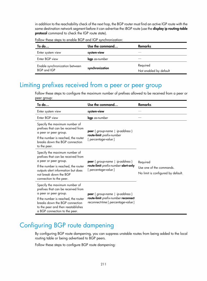
211
in addition to the reachability check of the next hop, the BGP router must find an active IGP route with the same destination network segment before it can advertise the iBGP route (use the display ip routing-table protocol command to check the IGP route state).
Follow these steps to enable BGP and IGP synchronization:
To do… Use the command… Remarks
Enter system view system-view —
Enter BGP view bgp as-number —
Enable synchronization between BGP and IGP synchronization
Required
Not enabled by default
Limiting prefixes received from a peer or peer group Follow these steps to configure the maximum number of prefixes allowed to be received from a peer or peer group:
To do… Use the command… Remarks
Enter system view system-view —
Enter BGP view bgp as-number —
Specify the maximum number of prefixes that can be received from a peer or peer group.
If the number is reached, the router breaks down the BGP connection to the peer.
peer { group-name | ip-address } route-limit prefix-number [ percentage-value ]
Required
Use one of the commands.
No limit is configured by default.
Specify the maximum number of prefixes that can be received from a peer or peer group.
If the number is reached, the router outputs alert information but does not break down the BGP connection to the peer.
peer { group-name | ip-address } route-limit prefix-number alert-only [ percentage-value ]
Specify the maximum number of prefixes that can be received from a peer or peer group.
If the number is reached, the router breaks down the BGP connection to the peer and then reestablishes a BGP connection to the peer.
peer { group-name | ip-address } route-limit prefix-number reconnect reconnect-time [ percentage-value ]
Configuring BGP route dampening By configuring BGP route dampening, you can suppress unstable routes from being added to the local routing table or being advertised to BGP peers.
Follow these steps to configure BGP route dampening:
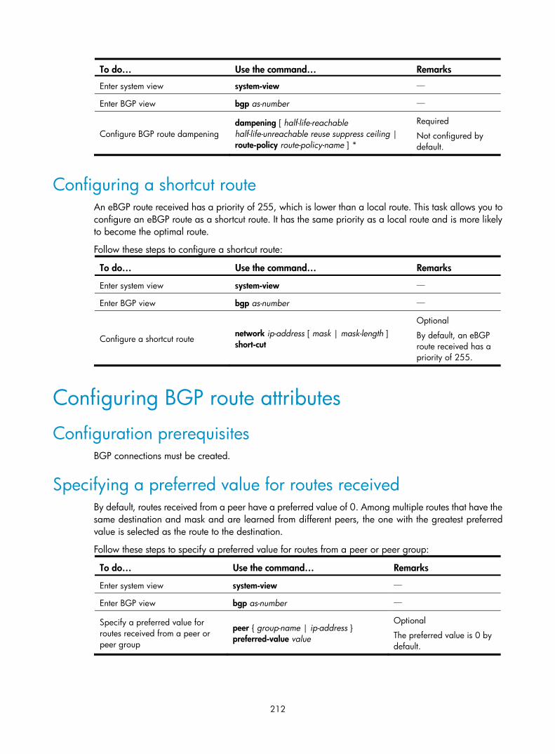
212
To do… Use the command… Remarks
Enter system view system-view —
Enter BGP view bgp as-number —
Configure BGP route dampening dampening [ half-life-reachable half-life-unreachable reuse suppress ceiling | route-policy route-policy-name ] *
Required
Not configured by default.
Configuring a shortcut route An eBGP route received has a priority of 255, which is lower than a local route. This task allows you to configure an eBGP route as a shortcut route. It has the same priority as a local route and is more likely to become the optimal route.
Follow these steps to configure a shortcut route:
To do… Use the command… Remarks
Enter system view system-view —
Enter BGP view bgp as-number —
Configure a shortcut route network ip-address [ mask | mask-length ] short-cut
Optional
By default, an eBGP route received has a priority of 255.
Configuring BGP route attributes
Configuration prerequisites BGP connections must be created.
Specifying a preferred value for routes received By default, routes received from a peer have a preferred value of 0. Among multiple routes that have the same destination and mask and are learned from different peers, the one with the greatest preferred value is selected as the route to the destination.
Follow these steps to specify a preferred value for routes from a peer or peer group:
To do… Use the command… Remarks
Enter system view system-view —
Enter BGP view bgp as-number —
Specify a preferred value for routes received from a peer or peer group
peer { group-name | ip-address } preferred-value value
Optional
The preferred value is 0 by default.

213
Configuring preferences for BGP routes A router can run multiple routing protocols with each having a preference. If they find the same route, the route found by the routing protocol with the highest preference is selected.
This task allows you to configure preferences for external, internal, and local BGP routes, and reference a routing policy to set preferences for matching routes as needed.
Follow these steps to configure preferences for BGP routes:
To do… Use the command… Remarks
Enter system view system-view —
Enter BGP view bgp as-number —
Configure preferences for external, internal, and local BGP routes
preference { external-preference internal-preference local-preference | route-policy route-policy-name }
Optional
The default preferences of external, internal, and local BGP routes are 255, 255, and 130, respectively.
Configure the default local preference The local preference is used to determine the best route for traffic leaving the local AS. When a BGP router obtains from several iBGP peers multiple routes to the same destination but with different next hops, it considers the route with the highest local preference as the best route.
This task allows you to specify the default local preference for routes sent to iBGP peers.
Follow these steps to specify the default local preference:
To do… Use the command… Remarks
Enter system view system-view —
Enter BGP view bgp as-number —
Configure the default local preference default local-preference value Optional
100 by default
Configuring the MED attribute MED is used to determine the best route for traffic going into an AS. When a BGP router obtains from eBGP peers multiple routes to the same destination but with different next hops, it considers the route with the smallest MED value as the best route if other conditions are the same.
Configure the default MED value
Follow these steps to configure the default MED value:
To do… Use the command… Remarks
Enter system view system-view —
Enter BGP view bgp as-number —

214
To do… Use the command… Remarks
Configure the default MED value default med med-value Optional
0 by default
Enable the comparison of MED of routes from different ASs
Follow these steps to enable the comparison of MED of routes from different ASs:
To do… Use the command… Remarks
Enter system view system-view —
Enter BGP view bgp as-number —
Enable the comparison of MED of routes from different ASs compare-different-as-med
Required
Not enabled by default
Enable the comparison of MED of routes from each AS
Route learning sequence may affect optimal route selection.
Figure 86 Route selection based on MED
As shown in Figure 86, Router D learns network 10.0.0.0 from both Router A and Router B. Because Router B has a smaller router ID, the route learned from it is optimal. Network NextHop MED LocPrf PrefVal Path/Ogn
*>i 10.0.0.0 2.2.2.2 50 0 300e
* i 3.3.3.3 50 0 200e
When Router D learns network 10.0.0.0 from Router C, it compares the route with the optimal route in its routing table. Because Router C and Router B reside in different ASs, BGP will not compare the MEDs of the two routes. Router C has a smaller router ID than Router B, the route from Router C becomes optimal. Network NextHop MED LocPrf PrefVal Path/Ogn
*>i 10.0.0.0 1.1.1.1 60 0 200e
* i 10.0.0.0 2.2.2.2 50 0 300e
* i 3.3.3.3 50 0 200e
However, Router C and Router A reside in the same AS, and Router C has a greater MED, so network 10.0.0.0 learned from Router C cannot be optimal.
You can configure the bestroute compare-med command on Router D. After that, Router D puts routes received from the same AS into a group. Router D then selects the route with the lowest MED from the same group, and compares routes from different groups. This mechanism avoids the above-mentioned

215
problem. The following output is the BGP routing table on Router D after the comparison of MED of routes from each AS is enabled. Network 10.0.0.0 learned from Router B is the optimal route. Network NextHop MED LocPrf PrefVal Path/Ogn
*>i 10.0.0.0 2.2.2.2 50 0 300e
* i 10.0.0.0 3.3.3.3 50 0 200e
* i 1.1.1.1 60 0 200e
BGP load balancing cannot be implemented because load balanced routes must have the same AS-path attribute.
Follow these steps to enable the comparison of MED of routes from each AS:
To do… Use the command… Remarks
Enter system view system-view —
Enter BGP view bgp as-number —
Enable the comparison of MED of routes from each AS
bestroute compare-med Optional
Not enabled by default
Enable the comparison of MED of routes from confederation peers
Follow these steps to enable the comparison of MED of routes from confederation peers:
To do… Use the command… Remarks
Enter system view system-view —
Enter BGP view bgp as-number —
Enable the comparison of MED of routes from confederation peers bestroute med-confederation
Optional
Not enabled by default
NOTE:
The MED attributes of routes from confederation peers are not compared if their AS-path attributes containAS numbers that do not belong to the confederation, such as these three routes: AS-path attributes of themare 65006 65009, 65007 65009, and 65008 65009; and MED values of them are 2, 3, and 1. Becausethe third route contains an AS number that does not belong to the confederation, the first route becomesthe optimal route.
Configuring the next hop attribute By default, when advertising routes to an iBGP peer or peer group, a BGP router does not set itself as the next hop. However, to ensure a BGP peer can find the correct next hop in some cases, you must configure the router as the next hop for routes sent to the peer.
For example, as shown in Figure 87, Router A and Router B establish an eBGP neighbor relationship, and Router B and Router C establish an iBGP neighbor relationship. When Router B advertises a network learned from Router A to Router C, if Router C has no route to IP address 1.1.1.1/24, you must configure Router B to set itself as the next hop (3.1.1.1/24) for the route to be sent to Router C.

216
Figure 87 Next hop attribute configuration 1
If a BGP router has two peers on a common broadcast network, it does not set itself as the next hop for routes sent to an eBGP peer by default. As shown in Figure 88, Router A and Router B establish an eBGP neighbor relationship, and Router B and Router C establish an iBGP neighbor relationship. They are on the same broadcast network 1.1.1.0/24. When Router B sends eBGP routes to Router A, it does not set itself as the next hop by default. However, you can configure Router B to set it as the next hop (1.1.1.2/24) for routes sent to Router A by using the peer next-hop-local command as needed.
Figure 88 Next hop attribute configuration 2
If you have configured BGP load balancing on a BGP router, the router will set it as the next hop for routes sent to an iBGP peer or peer group. This is done regardless of whether the peer next-hop-local command is configured.
Follow these steps to configure the next hop attribute:
To do… Use the command… Remarks
Enter system view system-view —
Enter BGP view bgp as-number —
Specify the router as the next hop of routes sent to a peer or peer group
peer { group-name | ip-address } next-hop-local
Optional
By default, the router sets it as the next hop for routes sent to an eBGP peer or peer group, but does not set it as the next hop for routes sent to an iBGP peer or peer group.
Configuring the AS-PATH attribute Permit local AS number to appear in routes from a peer or peer group
BGP checks whether the AS_PATH attribute of a route from a peer contains the local AS number. If so, it discards the route to avoid routing loops.
Follow these steps to permit local AS number to appear in routes from a peer or peer group and specify the appearance times.

217
To do… Use the command… Remarks
Enter system view system-view —
Enter BGP view bgp as-number —
Permit local AS number to appear in routes from a peer or peer group and specify the appearance times
peer { group-name | ip-address } allow-as-loop [ number ]
Optional
By default, the local AS number is not allowed.
Disable BGP from considering AS_PATH during best route selection
Follow these steps to disable BGP from considering AS_PATH during best route selection:
To do… Use the command… Remarks
Enter system view system-view —
Enter BGP view bgp as-number —
Disable BGP from considering AS_PATH during best route selection bestroute as-path-neglect
Optional
By default, BGP considers AS_PATH during best route selection.
Specify a fake AS number for a peer or peer group
When Router A in AS 2 is moved to AS 3, you can configure Router A to specify a fake AS number of 2 for created connections to eBGP peers or peer groups. In this way, these eBGP peers still think Router A is in AS 2 and need not change their configurations. This feature ensures uninterrupted BGP services.
Follow these steps to specify a fake AS number for a peer or peer group:
To do… Use the command… Remarks
Enter system view system-view —
Enter BGP view bgp as-number —
Specify a fake AS number for a peer or peer group
peer { group-name | ip-address } fake-as as-number
Optional
Not specified by default
NOTE:
This command is only applicable to an eBGP peer or peer group.
Configure AS number substitution
In L3VPN, if eBGP is used between PE and CE, sites in different geographical areas must have different AS numbers assigned to ensure correct route advertisement. If different CEs use the same AS number, you must configure the relevant PE to replace the AS number of the CE as its own AS number. This feature is used for route advertisement only.

218
Figure 89 AS number substitution configuration
MPLS backbone
VPNv4_Update:10.1.0.0/16RD:10.1.1.1/32AS_PATH:800
EBGP_Update:10.1.1.1/32AS_PATH:100,100
PE 1 PE 2
AS 800
EBGP_Update:10.1.1.1/32AS_PATH:800
AS 800
AS 100
CE 1 CE 2
As shown in the above figure, CE 1 and CE 2 use the same AS number of 800. If AS number substitution for CE 2 is configured on PE 2, and PE 2 receives a BGP update sent from CE 1, PE 2 replaces AS number 800 as its own AS number 100. Similar configuration must also be made on PE 1.
Follow these steps to configure AS number substitution for a peer or peer group:
To do… Use the command… Remarks
Enter system view system-view —
Enter BGP view bgp as-number —
Replace the AS number of a peer or peer group in the AS_PATH attribute as the local AS number
peer { group-name | ip-address } substitute-as
Required
Not configured by default.
CAUTION:
Improper AS number substitution configuration may cause route loops; use this command with caution.
Remove private AS numbers from updates to a peer or peer group
Follow these steps to remove private AS numbers from updates to a peer or peer group:
To do… Use the command… Remarks
Enter system view system-view —
Enter BGP view bgp as-number —
Configure BGP to remove private AS numbers from the AS_PATH attribute of updates to a peer or peer group
peer { group-name | ip-address } public-as-only
Required
By default, BGP updates carry private AS numbers.
Ignore the first AS number of eBGP route updates
Typically, BGP checks the AS_PATH attribute of a route update received from a peer. If the first AS number is not that of the BGP peer, the BGP router discards the route update.
Follow these steps to ignore the first AS number of eBGP route updates:
To do… Use the command… Remarks
Enter system view system-view —
Enter BGP view bgp as-number —

219
To do… Use the command… Remarks
Configure BGP to ignore the first AS number of eBGP route updates ignore-first-as
Required
By default, BGP checks the first AS number of eBGP route updates.
Tuning and optimizing BGP networks
Configuration prerequisites BGP connections must be created.
Configuring the BGP keepalive interval and holdtime After establishing a BGP connection, two routers send keepalive messages periodically to each other to keep the connection. If a router receives no keepalive or update message from the peer within the holdtime, it tears down the connection.
You can configure the keepalive interval and holdtime globally or for a specific peer or peer group. The actual keepalive interval and holdtime depend on the following cases:
• If the holdtime settings on the local and peer routers are different, the smaller one is used.
• If the keepalive interval is 0 and the negotiated holdtime is not 0, the actual keepalive interval equals one-third of the holdtime.
• If the keepalive interval is not 0, the actual keepalive interval is the smaller one between one third of the holdtime and the keepalive interval.
Follow these steps to configure BGP keepalive interval and holdtime:
To do… Use the command… Remarks
Enter system view system-view —
Enter BGP view bgp as-number —
Configure the global keepalive interval and holdtime
timer keepalive keepalive hold holdtime Optional
By default, the keepalive interval is 60 seconds, and holdtime is 180 seconds.
Configure the keepalive interval and holdtime for a peer or peer group
peer { group-name | ip-address } timer keepalive keepalive hold holdtime

220
NOTE:
• The maximum keepalive interval must be one third of the holdtime and no less than one second. The holdtime is no less than three seconds unless it is set to 0.
• The intervals set with the peer timer command are preferred to those set with the timer command.
• If the router has established a neighbor relationship with a peer, you must reset the BGP connection tovalidate the new set timers.
• The timer command takes effect for only new connections.
• After peer timer command is executed, the peer connection is closed at once, and a new connection tothe peer is negotiated using the configured hold time.
Configuring the interval for sending the same update Follow these steps to configure the interval for sending the same update to a peer or peer group:
To do… Use the command… Remarks
Enter system view system-view —
Enter BGP view bgp as-number —
Configure the interval for sending the same update to a peer or peer group
peer { group-name | ip-address } route-update-interval interval
Optional
The intervals for sending the same update to an iBGP peer and an eBGP peer default to 15 seconds and 30 seconds respectively.
Configuring BGP soft-reset After modifying the route selection policy, reset BGP connections to make the new one take effect.
The current BGP implementation supports the route-refresh feature that enables dynamic route refresh without tearing down BGP connections.
However, if a peer not supporting route-refresh exists in the network, you must configure the peer keep-all-routes command to save all routes from the peer, which are used during applying the new route selection policy.
Configure automatic soft-reset
After route refresh is enabled for peers and a policy is modified, the router advertises a route-refresh message to the peers, which then resend their routing information to the router. After receiving the routing information, the router performs dynamic route update by using the new policy.
Follow these steps to enable BGP route refresh for a peer or peer group:
To do… Use the command… Remarks
Enter system view system-view —
Enter BGP view bgp as-number —

221
To do… Use the command… Remarks
Enable BGP route refresh for a peer or peer group
peer { group-name | ip-address } capability-advertise route-refresh
Optional
Enabled by default
Configure manual soft-reset
If a BGP peer does not support route-refresh, you must save updates from the peer on the local router by using the peer keep-all-routes command, and use the refresh bgp command to refresh the BGP routing table.
Following these steps to save all route updates from a peer or peer group:
To do… Use the command… Remarks
Enter system view system-view —
Enter BGP view bgp as-number —
Disable BGP route-refresh and multi-protocol extension capability for a peer or peer group
peer { group-name | ip-address } capability-advertise conventional
Required
Enabled by default
Save all routes from a peer or peer group peer { group-name | ip-address } keep-all-routes
Required
Not saved by default
Return to user view return —
Perform manual soft reset on BGP connections
refresh bgp { all | ip-address | group group-name | external | internal } { export | import }
Required
NOTE:
If the BGP peer does not support route-refresh and the peer keep-all-routes command is not configured for it, you need to decide whether to manually disconnect the peer to learn routes again according to theimpact of the new policy.
Enabling the BGP ORF capability The BGP Outbound Route Filtering (ORF) feature allows a BGP speaker to send its BGP peer a set of ORFs through route-refresh messages. The peer then applies the ORFs, in addition to its local routing policies (if any), to filter updates to the BGP speaker, reducing the number of exchanged Update messages and saving network resources.
After you enable the BGP ORF capability, the local BGP router negotiates the ORF capability with the BGP peer through Open messages (determines whether to carry ORF information in messages, and if yes, whether to carry non-standard ORF information in the packets). After completing the negotiation process and establishing the neighboring relationship, the BGP router and its BGP peer can exchange ORF information through specific route-refresh messages.
For the parameters configured on both sides for ORF capability negotiation, see Table 5.
Follow these steps to enable the BGP ORF capability:

222
To do… Use the command… Remarks
Enter system view system-view —
Enter BGP view bgp as-number —
Enable BGP route refresh for a peer or peer group
peer { group-name | ip-address } capability-advertise route-refresh
Required
Enabled by default.
Enable the non-standard ORF capability for a BGP peer or peer group
peer { group-name | ip-address } capability-advertise orf non-standard
Optional
By default, standard BGP ORF capability defined in RFC 5291 and RFC 5292 is supported.
If the peer supports only non-standard ORF, you need to configure this command.
Enable the ORF capability for a BGP peer or peer group
peer { group-name | ip-address } capability-advertise orf ip-prefix { both | receive | send }
Required
Disabled by default.
Table 5 Description of the both, send, and receive parameters and the negotiation result
Local parameter Peer parameter Negotiation result
send receive The ORF sending capability is enabled locally and the
ORF receiving capability is enabled on the peer. both
receive send The ORF receiving capability is enabled locally and the
ORF sending capability is enabled on the peer. both
both both Both the ORF sending and receiving capabilities are enabled locally and on the peer, respectively.
Enabling 4-byte AS number suppression When a switch that supports 4-byte AS numbers sends an Open message for peer relationship establishment, the Optional parameters field of the message indicates that the AS number occupies four bytes—in the range of 1 to 4294967295. If the peer device does not support 4-byte AS numbers (for examples, it supports only 2-byte AS numbers), the peer relationship cannot be established.
After you enable the 4-byte AS number suppression function, the peer device can then process the Open message even though it does not support 4-byte AS numbers, and the BGP peer relationship can be established.
Follow these steps to enable 4-byte AS number suppression:
To do… Use the command… Remarks
Enter system view system-view —
Enter BGP view bgp as-number —
Enable 4-byte AS number suppression
peer { group-name | ip-address } capability-advertise suppress-4-byte-as
Required
Disabled by default.
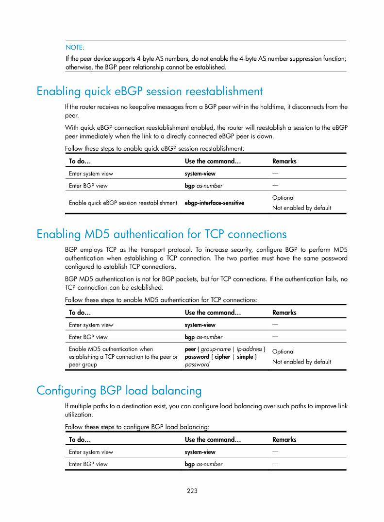
223
NOTE:
If the peer device supports 4-byte AS numbers, do not enable the 4-byte AS number suppression function;otherwise, the BGP peer relationship cannot be established.
Enabling quick eBGP session reestablishment If the router receives no keepalive messages from a BGP peer within the holdtime, it disconnects from the peer.
With quick eBGP connection reestablishment enabled, the router will reestablish a session to the eBGP peer immediately when the link to a directly connected eBGP peer is down.
Follow these steps to enable quick eBGP session reestablishment:
To do… Use the command… Remarks
Enter system view system-view —
Enter BGP view bgp as-number —
Enable quick eBGP session reestablishment ebgp-interface-sensitive Optional
Not enabled by default
Enabling MD5 authentication for TCP connections BGP employs TCP as the transport protocol. To increase security, configure BGP to perform MD5 authentication when establishing a TCP connection. The two parties must have the same password configured to establish TCP connections.
BGP MD5 authentication is not for BGP packets, but for TCP connections. If the authentication fails, no TCP connection can be established.
Follow these steps to enable MD5 authentication for TCP connections:
To do… Use the command… Remarks
Enter system view system-view —
Enter BGP view bgp as-number —
Enable MD5 authentication when establishing a TCP connection to the peer or peer group
peer { group-name | ip-address } password { cipher | simple } password
Optional
Not enabled by default
Configuring BGP load balancing If multiple paths to a destination exist, you can configure load balancing over such paths to improve link utilization.
Follow these steps to configure BGP load balancing:
To do… Use the command… Remarks
Enter system view system-view —
Enter BGP view bgp as-number —

224
To do… Use the command… Remarks
Configure the maximum number of BGP routes for load balancing
balance number Optional
Load balancing is not enabled by default.
Forbiding session establishment with a peer or peer group Follow these steps to forbid session establishment with a peer or peer group:
To do… Use the command… Remarks
Enter system view system-view —
Enter BGP view bgp as-number —
Forbid session establishment with a peer or peer group
peer { group-name | ip-address } ignore
Optional
Not forbidden by default
Configuring a large scale BGP network In a large-scale BGP network, configuration and maintenance become difficult because of the large numbers of BGP peers. To facilitate configuration, you can configure peer group, community, route reflector, or confederation as needed.
Configuration prerequisites Peering nodes are accessible to each other at the network layer.
Configuring BGP peer groups A peer group is a group of peers with the same route selection policy.
In a large-scale network, many peers may use the same route selection policy. You can configure a peer group and add these peers into this group. In this way, peers can share the same policy as the peer group. When the policy of the group is modified, the modification also applies to peers in it, simplifying configuration.
A peer group is an iBGP peer group if peers in it belong to the same AS, and is an eBGP peer group if peers in it belong to different ASs.
If a peer group has peers added, you cannot remove its AS number using the undo form of the command or change its AS number.
Configure an iBGP peer group
After you create an iBGP peer group and then add a peer into it, the system creates the peer in BGP view and specifies the local AS number for the peer.
Follow these steps to configure an iBGP peer group:
To do… Use the command… Remarks
Enter system view system-view —

225
To do… Use the command… Remarks
Enter BGP view bgp as-number —
Create an iBGP peer group group group-name [ internal ] Required
Add a peer into the iBGP peer group
peer ip-address group group-name Required
Configure an eBGP peer group
If peers in an eBGP group belong to the same external AS, the eBGP peer group is a pure eBGP peer group; if not, it is a mixed eBGP peer group.
Use one of the following approaches to configure an eBGP peer group:
• Create the eBGP peer group, specify its AS number, and add peers into it. All the added peers share the same AS number.
• Create the eBGP peer group, specify an AS number for a peer, and add the peer into the peer group.
• Create the eBGP peer group and add a peer into it with an AS number specified.
Follow these steps to configure an eBGP peer group using the first approach:
To do… Use the command… Remarks
Enter system view system-view —
Enter BGP view bgp as-number —
Create an eBGP peer group group group-name external Required
Specify the AS number for the group
peer group-name as-number as-number Required
Add the peer into the group peer ip-address group group-name Required
NOTE:
• Do not specify any AS number for a peer before adding it into the peer group.
• All of the added peers have the same AS number as that of the peer group.
Follow these steps to configure an eBGP peer group using the second approach:
To do… Use the command… Remarks
Enter system view system-view —
Enter BGP view bgp as-number —
Create an eBGP peer group group group-name external Required
Specify an AS number for a peer peer ip-address as-number as-number
Required

226
To do… Use the command… Remarks
Add the peer into the group peer ip-address group group-name [ as-number as-number ]
Required
The AS number can be either specified or not specified in the command. If specified, the AS number must be the same as that specified for the peer with the peer ip-address as-number as-number command.
NOTE:
Peers added in the group can have different AS numbers.
Follow these steps to configure an eBGP peer group using the third approach:
To do… Use the command… Remarks
Enter system view system-view —
Enter BGP view bgp as-number —
Create an eBGP peer group group group-name external Required
Add a peer into the group and specify its AS number
peer ip-address group group-name as-number as-number
Required
NOTE:
• Do not specify any AS number for a peer before adding it into the peer group.
• Peers added in the group can have different AS numbers.
Configuring BGP community A BGP community is a group of destinations with the same characteristics. It has no geographical boundaries and is independent of ASs.
You can configure a routing policy to define which destinations belong to a BGP community and then advertise the community attribute to a peer or peer group.
You can apply a routing policy to filter routes advertised to or received from a peer or peer group according to the community attribute, which helps simplify policy configuration and management.
For how to configure a routing policy, see the chapter “Routing policy configuration.”
Follow these steps to configure BGP community:
To do… Use the command… Remarks
Enter system view system-view —
Enter BGP view bgp as-number —
Advertise the community attribute to a peer
Advertise the community attribute to a peer or peer group
peer { group-name | ip-address } advertise-community
Required
Not configured by

227
To do… Use the command… Remarks or peer group Advertise the extended
community attribute to a peer or peer group
peer { group-name | ip-address } advertise-ext-community
default.
Apply a routing policy to routes advertised to a peer or peer group
peer { group-name | ip-address } route-policy route-policy-name export
Required
Not configured by default.
Configuring a BGP route reflector If an AS has many BGP routers, you can configure them as a cluster by configuring one of them as a route reflector and others as clients to reduce iBGP connections.
To enhance network reliability and prevent single point of failure, specify multiple route reflectors for a cluster. The route reflectors in the cluster must have the same cluster ID to avoid routing loops.
Follow these steps to configure a BGP route reflector:
To do… Use the command… Remarks
Enter system view system-view —
Enter BGP view bgp as-number —
Configure the router as a route reflector and specify a peer or peer group as its client
peer { group-name | ip-address } reflect-client
Required
Not configured by default.
Enable route reflection between clients
reflect between-clients Optional
Enabled by default
Configure the cluster ID of the route reflector
reflector cluster-id cluster-id Optional
By default, a route reflector uses its router ID as the cluster ID.
CAUTION:
• It is not required to make clients of a route reflector fully meshed. The route reflector forwards routing information between clients. If clients are fully meshed, disable route reflection between clients to reducerouting costs.
• Generally, a cluster has only one route reflector, and the router ID is used to identify the cluster. You canconfigure multiple route reflectors to improve network stability. To avoid routing loops, specify the samecluster ID for these route reflectors by using the reflector cluster-id command.
Configuring a BGP confederation Configuring a BGP confederation is another way for reducing iBGP connections in an AS.
A confederation contains sub ASs. In each sub AS, iBGP peers are fully meshed. Between sub ASs, eBGP connections are established.
If routers not compliant with RFC 3065 exist in the confederation, use the confederation nonstandard command to make the local router compatible with these routers.

228
Configure a BGP confederation
After you split an AS into multiple sub ASs, you can configure a router in a sub AS as follows:
1. Enable BGP and specify the AS number of the router.
2. Specify the confederation ID. From an outsider’s perspective, the sub ASs of the confederation is a single AS, which is identified by the confederation ID.
3. If the router must establish eBGP connections to other sub ASs, you must specify the peering sub ASs in the confederation.
A confederation contains a maximum of 32 sub ASs. The AS number of a sub AS is effective only in the confederation.
Follow these steps to configure a BGP confederation:
To do… Use the command… Remarks
Enter system view system-view —
Enter BGP view bgp as-number —
Configure a confederation ID confederation id as-number Required
Not configured by default.
Specify peering sub ASs in the confederation confederation peer-as as-number-list
Required
Not configured by default.
Configure confederation compatibility
If some other routers in the confederation do not comply with RFC 3065, enable confederation compatibility to allow the router to work with those routers.
Follow these steps to configure confederation compatibility:
To do… Use the command… Remarks
Enter system view system-view —
Enter BGP view bgp as-number —
Enable compatibility with routers not compliant with RFC 3065 in the confederation
confederation nonstandard Optional
Not enabled by default
Configuring BGP GR Perform the following configuration on the GR Restarter and GR Helper, respectively.
NOTE:
A device can act as a GR Restarter and GR Helper at the same time.
Follow these steps to configure BGP GR:
To do… Use the command… Remarks
Enter system view system-view —

229
To do… Use the command… Remarks
Enable BGP and enter its view bgp as-number —
Enable GR Capability for BGP graceful-restart Required
Disabled by default
Configure the maximum time allowed for the peer to reestablish a BGP session
graceful-restart timer restart timer
Optional
150 seconds by default
Configure the maximum time to wait for the End-of-RIB marker
graceful-restart timer wait-for-rib timer
Optional
180 seconds by default
NOTE:
• The maximum time allowed for the peer (the GR restarter) to reestablish a BGP session must be less thanthe Holdtime carried in the Open message.
• The End-Of-RIB (End of Routing-Information-Base) indicates the end of route updates.
Enabling trap After trap is enabled for BGP, BGP generates Level-4 traps to report important events. The generated traps are sent to the information center of the device. The trap output rules (whether to output the traps and the output direction) are determined according to the information center configuration. (For information center configuration, see Network Management and Monitoring Configuration Guide.)
Follow these steps to enable trap:
To do… Use the command… Remarks
Enter system view system-view —
Enable trap for BGP snmp-agent trap enable bgp Optional
Enabled by default
Enabling logging of peer state changes Follow these steps to enable the logging of peer state changes:
To do… Use the command… Remarks
Enter system view system-view —
Enter BGP view bgp as-number —
Enable the logging of peer state changes globally log-peer-change
Optional
Enabled by default
Enable the logging of peer state changes for a peer or peer group
peer { group-name | ip-address } log-change
Optional
Enabled by default
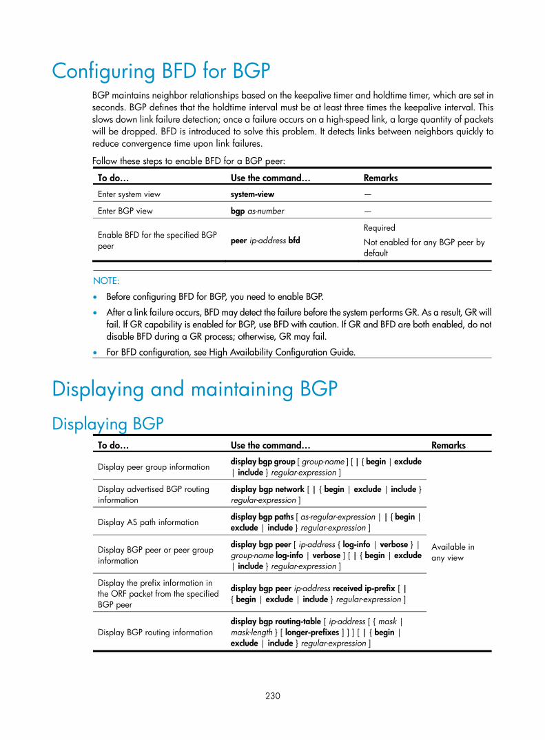
230
Configuring BFD for BGP BGP maintains neighbor relationships based on the keepalive timer and holdtime timer, which are set in seconds. BGP defines that the holdtime interval must be at least three times the keepalive interval. This slows down link failure detection; once a failure occurs on a high-speed link, a large quantity of packets will be dropped. BFD is introduced to solve this problem. It detects links between neighbors quickly to reduce convergence time upon link failures.
Follow these steps to enable BFD for a BGP peer:
To do… Use the command… Remarks
Enter system view system-view —
Enter BGP view bgp as-number —
Enable BFD for the specified BGP peer
peer ip-address bfd Required
Not enabled for any BGP peer by default
NOTE:
• Before configuring BFD for BGP, you need to enable BGP.
• After a link failure occurs, BFD may detect the failure before the system performs GR. As a result, GR willfail. If GR capability is enabled for BGP, use BFD with caution. If GR and BFD are both enabled, do notdisable BFD during a GR process; otherwise, GR may fail.
• For BFD configuration, see High Availability Configuration Guide.
Displaying and maintaining BGP
Displaying BGP To do… Use the command… Remarks
Display peer group information display bgp group [ group-name ] [ | { begin | exclude | include } regular-expression ]
Available in any view
Display advertised BGP routing information
display bgp network [ | { begin | exclude | include } regular-expression ]
Display AS path information display bgp paths [ as-regular-expression | | { begin | exclude | include } regular-expression ]
Display BGP peer or peer group information
display bgp peer [ ip-address { log-info | verbose } | group-name log-info | verbose ] [ | { begin | exclude | include } regular-expression ]
Display the prefix information in the ORF packet from the specified BGP peer
display bgp peer ip-address received ip-prefix [ | { begin | exclude | include } regular-expression ]
Display BGP routing information display bgp routing-table [ ip-address [ { mask | mask-length } [ longer-prefixes ] ] ] [ | { begin | exclude | include } regular-expression ]

231
To do… Use the command… Remarks
Display routing information matching the AS path ACL
display bgp routing-table as-path-acl as-path-acl-number [ | { begin | exclude | include } regular-expression ]
Display BGP CIDR routing information
display bgp routing-table cidr [ | { begin | exclude | include } regular-expression ]
Display BGP routing information matching the specified BGP community
display bgp routing-table community [ aa:nn&<1-13> ] [ no-advertise | no-export | no-export-subconfed ] * [ whole-match ] [ | { begin | exclude | include } regular-expression ]
Display routing information matching a BGP community list
display bgp routing-table community-list { { basic-community-list-number | comm-list-name } [ whole-match ] | adv-community-list-number } [ | { begin | exclude | include } regular-expression ]
Display BGP dampened routing information
display bgp routing-table dampened [ | { begin | exclude | include } regular-expression ]
Display BGP dampening parameter information
display bgp routing-table dampening parameter [ | { begin | exclude | include } regular-expression ]
Display BGP routing information originating from different ASs
display bgp routing-table different-origin-as [ | { begin | exclude | include } regular-expression ]
Display BGP routing flap statistics
display bgp routing-table flap-info [ regular-expression as-regular-expression | [ as-path-acl as-path-acl-number | ip-address [ { mask | mask-length } [ longer-match ] ] ] [ | { begin | exclude | include } regular-expression ] ]
Display labeled BGP routing information
display bgp routing-table label [ | { begin | exclude | include } regular-expression ]
Display routing information to or from a peer
display bgp routing-table peer ip-address { advertised-routes | received-routes } [ network-address [ mask | mask-length ] | statistic ] [ | { begin | exclude | include } regular-expression ]
Display routing information matching a regular expression
display bgp routing-table regular-expression as-regular-expression
Display BGP routing statistics display bgp routing-table statistic [ | { begin | exclude | include } regular-expression ]
Display the global router ID display router id [ | { begin | exclude | include } regular-expression ]
Resetting BGP connections To do… Use the command… Remarks
Reset all BGP connections reset bgp all
Available in user view
Reset the BGP connections to an AS reset bgp as-number
Reset the BGP connection to a peer reset bgp ip-address [ flap-info ]
Reset all eBGP connections reset bgp external

232
To do… Use the command… Remarks
Reset the BGP connections to a peer group reset bgp group group-name
Reset all iBGP connections reset bgp internal
Reset all IPv4 unicast BGP connections reset bgp ipv4 all
Clearing BGP information To do… Use the command… Remarks
Clear dampened BGP routing information and release suppressed routes
reset bgp dampening [ ip-address [ mask | mask-length ] ]
Available in user view
Clear route flap information reset bgp flap-info [ ip-address [ mask-length | mask ] | as-path-acl as-path-acl-number | regexp as-path-regular-expression ]
BGP configuration examples
BGP basic configuration Network requirements
In Figure 90, run eBGP between Switch A and Switch B and iBGP between Switch B and Switch C so that Switch C can access the network 8.1.1.0/24 connected to Router A.
Figure 90 Network diagram
Configuration procedure
1. Configure IP addresses for interfaces. (Details not shown)
2. Configure iBGP.
• To prevent route flapping caused by port state changes, this example uses loopback interfaces to establish iBGP connections.
• Because loopback interfaces are virtual interfaces, you need to use the peer connect-interface command to specify the loopback interface as the source interface for establishing BGP connections.
• Enable OSPF in AS 65009 to make sure that Switch B can communicate with Switch C through loopback interfaces.
# Configure Switch B.

233
<SwitchB> system-view
[SwitchB] bgp 65009
[SwitchB-bgp] router-id 2.2.2.2
[SwitchB-bgp] peer 3.3.3.3 as-number 65009
[SwitchB-bgp] peer 3.3.3.3 connect-interface loopback 0
[SwitchB-bgp] quit
[SwitchB] ospf 1
[SwitchB-ospf-1] area 0
[SwitchB-ospf-1-area-0.0.0.0] network 2.2.2.2 0.0.0.0
[SwitchB-ospf-1-area-0.0.0.0] network 9.1.1.1 0.0.0.255
[SwitchB-ospf-1-area-0.0.0.0] quit
[SwitchB-ospf-1] quit
# Configure Switch C. <SwitchC> system-view
[SwitchC] bgp 65009
[SwitchC-bgp] router-id 3.3.3.3
[SwitchC-bgp] peer 2.2.2.2 as-number 65009
[SwitchC-bgp] peer 2.2.2.2 connect-interface loopback 0
[SwitchC-bgp] quit
[SwitchC] ospf 1
[SwitchC-ospf-1] area 0
[SwitchC-ospf-1-area-0.0.0.0] network 3.3.3.3 0.0.0.0
[SwitchC-ospf-1-area-0.0.0.0] network 9.1.1.0 0.0.0.255
[SwitchC-ospf-1-area-0.0.0.0] quit
[SwitchC-ospf-1] quit
[SwitchC] display bgp peer
BGP local router ID : 3.3.3.3
Local AS number : 65009
Total number of peers : 1 Peers in established state : 1
Peer AS MsgRcvd MsgSent OutQ PrefRcv Up/Down State
2.2.2.2 65009 2 2 0 0 00:00:13 Established
The output information shows that Switch C has established an iBGP peer relationship with Switch B.
3. Configure eBGP.
• The eBGP peers, Switch A and Switch B (usually belong to different carriers), are located in different ASs. Typically, their loopback interfaces are not reachable to each other, so directly connected interfaces are used for establishing BGP sessions.
• To enable Switch C to access the network 8.1.1.0/24 connected directly to Switch A, inject network 8.1.1.0/24 to the BGP routing table of Switch A.
# Configure Switch A. <SwitchA> system-view
[SwitchA] bgp 65008
[SwitchA-bgp] router-id 1.1.1.1
[SwitchA-bgp] peer 3.1.1.1 as-number 65009
[SwitchA-bgp] network 8.1.1.1 24

234
[SwitchA-bgp] quit
# Configure Switch B. [SwitchB] bgp 65009
[SwitchB-bgp] peer 3.1.1.2 as-number 65008
[SwitchB-bgp] quit
# Display BGP peer information on Switch B. [SwitchB] display bgp peer
BGP local router ID : 2.2.2.2
Local AS number : 65009
Total number of peers : 2 Peers in established state : 2
Peer AS MsgRcvd MsgSent OutQ PrefRcv Up/Down State
3.3.3.3 65009 4 4 0 0 00:02:49 Established
3.1.1.2 65008 2 2 0 0 00:00:05 Established
The output shows that Switch B has established an iBGP peer relationship with Switch C and an eBGP peer relationship with Switch A.
# Display the BGP routing table on Switch A. [SwitchA] display bgp routing-table
Total Number of Routes: 1
BGP Local router ID is 1.1.1.1
Status codes: * - valid, ^ - VPNv4 best, > - best, d - damped,
h - history, i - internal, s - suppressed, S - Stale
Origin : i - IGP, e - EGP, ? - incomplete
Network NextHop MED LocPrf PrefVal Path/Ogn
*> 8.1.1.0/24 0.0.0.0 0 0 i
# Display the BGP routing table on Switch B. [SwitchB] display bgp routing-table
Total Number of Routes: 1
BGP Local router ID is 2.2.2.2
Status codes: * - valid, ^ - VPNv4 best, > - best, d - damped,
h - history, i - internal, s - suppressed, S - Stale
Origin : i - IGP, e - EGP, ? - incomplete
Network NextHop MED LocPrf PrefVal Path/Ogn
*> 8.1.1.0/24 3.1.1.2 0 0 65008i
# Display the BGP routing table on Switch C. [SwitchC] display bgp routing-table

235
Total Number of Routes: 1
BGP Local router ID is 3.3.3.3
Status codes: * - valid, ^ - VPNv4 best, > - best, d - damped,
h - history, i - internal, s - suppressed, S - Stale
Origin : i - IGP, e - EGP, ? - incomplete
Network NextHop MED LocPrf PrefVal Path/Ogn
i 8.1.1.0/24 3.1.1.2 0 100 0 65008i
NOTE:
The outputs show that Switch A has learned no route to AS65009, and Switch C has learned network 8.1.1.0 but the next hop 3.1.1.2 is unreachable, so the route is invalid.
4. Redistribute direct routes.
Configure BGP to redistribute direct routes on Switch B, so that Switch A can obtain the route to 9.1.1.0/24 and Switch C can obtain the route to 3.1.1.0/24.
# Configure Switch B. [SwitchB] bgp 65009
[SwitchB-bgp] import-route direct
# Display the BGP routing table on Switch A. [SwitchA] display bgp routing-table
Total Number of Routes: 4
BGP Local router ID is 1.1.1.1
Status codes: * - valid, ^ - VPNv4 best, > - best, d - damped,
h - history, i - internal, s - suppressed, S - Stale
Origin : i - IGP, e - EGP, ? – incomplete
Network NextHop MED LocPrf PrefVal Path/Ogn
*> 2.2.2.2/32 3.1.1.1 0 0 65009?
* 3.1.1.0/24 3.1.1.1 0 0 65009?
*> 8.1.1.0/24 0.0.0.0 0 0 i
*> 9.1.1.0/24 3.1.1.1 0 0 65009?
Two routes 2.2.2.2/32 and 9.1.1.0/24 have been added in Switch A’s routing table.
# Display the BGP routing table on Switch C. [SwitchC] display bgp routing-table
Total Number of Routes: 4
BGP Local router ID is 3.3.3.3
Status codes: * - valid, ^ - VPNv4 best, > - best, d - damped,
h - history, i - internal, s - suppressed, S - Stale

236
Origin : i - IGP, e - EGP, ? - incomplete
Network NextHop MED LocPrf PrefVal Path/Ogn
i 2.2.2.2/32 2.2.2.2 0 100 0 ?
*>i 3.1.1.0/24 2.2.2.2 0 100 0 ?
*>i 8.1.1.0/24 3.1.1.2 0 100 0 65008i
* i 9.1.1.0/24 2.2.2.2 0 100 0 ?
The output shows that the route 8.1.1.0 becomes valid with the next hop as Switch A.
5. Verification.
# Ping 8.1.1.1 on Switch C. [SwitchC] ping 8.1.1.1
PING 8.1.1.1: 56 data bytes, press CTRL_C to break
Reply from 8.1.1.1: bytes=56 Sequence=1 ttl=254 time=2 ms
Reply from 8.1.1.1: bytes=56 Sequence=2 ttl=254 time=2 ms
Reply from 8.1.1.1: bytes=56 Sequence=3 ttl=254 time=2 ms
Reply from 8.1.1.1: bytes=56 Sequence=4 ttl=254 time=2 ms
Reply from 8.1.1.1: bytes=56 Sequence=5 ttl=254 time=2 ms
--- 8.1.1.1 ping statistics ---
5 packet(s) transmitted
5 packet(s) received
0.00% packet loss
round-trip min/avg/max = 2/2/2 ms
BGP and IGP synchronization configuration Network requirements
As shown in Figure 91, all devices of company A belong to AS 65008, and all devices of company B belong to AS 65009. AS 65008 and AS 65009 are connected through Switch A and Switch B. Switch A must be able to access network 9.1.2.0/24 in AS 65009, and Switch C must access network 8.1.1.0/24 in AS 65008.
Figure 91 Network diagram
Configuration procedure
1. Configure IP addresses for interfaces. (Details not shown)
2. Configure OSPF.
Enable OSPF in AS 65009, so that Switch B can obtain the route to 9.1.2.0/24.
# Configure Switch B.

237
<SwitchB> system-view
[SwitchB] ospf 1
[SwitchB-ospf-1] area 0
[SwitchB-ospf-1-area-0.0.0.0] network 2.2.2.2 0.0.0.0
[SwitchB-ospf-1-area-0.0.0.0] network 9.1.1.0 0.0.0.255
[SwitchB-ospf-1-area-0.0.0.0] quit
[SwitchB-ospf-1] quit
# Configure Switch C. <SwitchC> system-view
[SwitchC] ospf 1
[SwitchC-ospf-1] import-route direct
[SwitchC-ospf-1] area 0
[SwitchC-ospf-1-area-0.0.0.0] network 9.1.1.0 0.0.0.255
[SwitchC-ospf-1-area-0.0.0.0] quit
[SwitchC-ospf-1] quit
3. Configure the eBGP connection.
Configure the eBGP connection and inject network 8.1.1.0/24 to the BGP routing table of Switch A, so that Switch B can obtain the route to 8.1.1.0/24.
# Configure Switch A. <SwitchA> system-view
[SwitchA] bgp 65008
[SwitchA-bgp] router-id 1.1.1.1
[SwitchA-bgp] peer 3.1.1.1 as-number 65009
[SwitchA-bgp] network 8.1.1.0 24
[SwitchA-bgp] quit
# Configure Switch B. [SwitchB] bgp 65009
[SwitchB-bgp] router-id 2.2.2.2
[SwitchB-bgp] peer 3.1.1.2 as-number 65008
4. Configure BGP and IGP synchronization.
• Configure BGP to redistribute routes from OSPF on Switch B, so that Switch A can obtain the route to 9.1.2.0/24.
• Configure OSPF to redistribute routes from BGP on Switch B, so that Switch C can obtain the route to 8.1.1.0/24.
# Configure BGP to redistribute routes from OSPF on Switch B. [SwitchB-bgp] import-route ospf 1
[SwitchB-bgp] quit
[SwitchB] ospf 1
[SwitchB-ospf-1] import-route bgp
[SwitchB-ospf-1] quit
# Display the BGP routing table on Switch A. [SwitchA] display bgp routing-table
Total Number of Routes: 3
BGP Local router ID is 1.1.1.1

238
Status codes: * - valid, ^ - VPNv4 best, > - best, d - damped,
h - history, i - internal, s - suppressed, S - Stale
Origin : i - IGP, e - EGP, ? - incomplete
Network NextHop MED LocPrf PrefVal Path/Ogn
*> 3.3.3.3/32 3.1.1.1 1 0 65009?
*> 8.1.1.0/24 0.0.0.0 0 0 i
*> 9.1.2.0/24 3.1.1.1 1 0 65009?
# Display the routing table on Switch C. [SwitchC] display ip routing-table
Routing Tables: Public
Destinations : 9 Routes : 9
Destination/Mask Proto Pre Cost NextHop Interface
2.2.2.2/32 OSPF 10 1 9.1.1.1 Vlan300
3.3.3.3/32 Direct 0 0 127.0.0.1 InLoop0
8.1.1.0/24 O_ASE 150 1 9.1.1.1 Vlan300
9.1.1.0/24 Direct 0 0 9.1.1.2 Vlan300
9.1.1.2/32 Direct 0 0 127.0.0.1 InLoop0
9.1.2.0/24 Direct 0 0 9.1.2.1 Vlan400
9.1.2.1/32 Direct 0 0 127.0.0.1 InLoop0
127.0.0.0/8 Direct 0 0 127.0.0.1 InLoop0
127.0.0.1/32 Direct 0 0 127.0.0.1 InLoop0
5. Verification.
# Use ping for verification. [SwitchA] ping -a 8.1.1.1 9.1.2.1
PING 9.1.2.1: 56 data bytes, press CTRL_C to break
Reply from 9.1.2.1: bytes=56 Sequence=1 ttl=254 time=15 ms
Reply from 9.1.2.1: bytes=56 Sequence=2 ttl=254 time=31 ms
Reply from 9.1.2.1: bytes=56 Sequence=3 ttl=254 time=47 ms
Reply from 9.1.2.1: bytes=56 Sequence=4 ttl=254 time=46 ms
Reply from 9.1.2.1: bytes=56 Sequence=5 ttl=254 time=47 ms
--- 9.1.2.1 ping statistics ---
5 packet(s) transmitted
5 packet(s) received
0.00% packet loss
round-trip min/avg/max = 15/37/47 ms
[SwitchC] ping -a 9.1.2.1 8.1.1.1
PING 8.1.1.1: 56 data bytes, press CTRL_C to break
Reply from 8.1.1.1: bytes=56 Sequence=1 ttl=254 time=2 ms
Reply from 8.1.1.1: bytes=56 Sequence=2 ttl=254 time=2 ms
Reply from 8.1.1.1: bytes=56 Sequence=3 ttl=254 time=2 ms
Reply from 8.1.1.1: bytes=56 Sequence=4 ttl=254 time=2 ms
Reply from 8.1.1.1: bytes=56 Sequence=5 ttl=254 time=2 ms

239
--- 8.1.1.1 ping statistics ---
5 packet(s) transmitted
5 packet(s) received
0.00% packet loss
round-trip min/avg/max = 2/2/2 ms
BGP load balancing configuration Network requirements
As shown in Figure 92, all the switches run BGP. Switch A resides in AS 65008, Switch B and Switch C in AS 65009. Between Switch A and Switch B, Switch A and Switch C are eBGP connections, and between Switch B and Switch C is an iBGP connection. Two routes are configured on Switch A for load balancing.
Figure 92 Network diagram
Configuration procedure
1. Configure IP addresses for interfaces. (Details not shown)
2. Configure BGP connections.
• On Switch A, establish eBGP connections with Switch B and Switch C respectively; configure BGP to advertise network 8.1.1.0/24 to Switch B and Switch C, so that Switch B and Switch C can access the internal network connected to Switch A.
• On Switch B, establish an eBGP connection with Switch A and an iBGP connection with Switch C; configure BGP to advertise network 9.1.1.0/24 to Switch A, so that Switch A can access the intranet through Switch B; configure a static route to interface loopback 0 on Switch C (or use a routing protocol like OSPF) to establish the iBGP connection.
• On Switch C, establish an eBGP connection with Switch A and an iBGP connection with Switch B; configure BGP to advertise network 9.1.1.0/24 to Switch A, so that Switch A can access the intranet through Switch C; configure a static route to interface loopback 0 on Switch B (or use another protocol like OSPF) to establish the iBGP connection.
# Configure Switch A. <SwitchA> system-view
[SwitchA] bgp 65008

240
[SwitchA-bgp] router-id 1.1.1.1
[SwitchA-bgp] peer 3.1.1.1 as-number 65009
[SwitchA-bgp] peer 3.1.2.1 as-number 65009
[SwitchA-bgp] network 8.1.1.1 24
[SwitchA-bgp] quit
# Configure Switch B. <SwitchB> system-view
[SwitchB] bgp 65009
[SwitchB-bgp] router-id 2.2.2.2
[SwitchB-bgp] peer 3.1.1.2 as-number 65008
[SwitchB-bgp] peer 3.3.3.3 as-number 65009
[SwitchB-bgp] peer 3.3.3.3 connect-interface loopback 0
[SwitchB-bgp] network 9.1.1.0 255.255.255.0
[SwitchB-bgp] quit
[SwitchB] ip route-static 3.3.3.3 32 9.1.1.2
# Configure Switch C. <SwitchC> system-view
[SwitchC] bgp 65009
[SwitchC-bgp] router-id 3.3.3.3
[SwitchC-bgp] peer 3.1.2.2 as-number 65008
[SwitchC-bgp] peer 2.2.2.2 as-number 65009
[SwitchC-bgp] peer 2.2.2.2 connect-interface loopback 0
[SwitchC-bgp] network 9.1.1.0 255.255.255.0
[SwitchC-bgp] quit
[SwitchC] ip route-static 2.2.2.2 32 9.1.1.1
# Display the BGP routing table on Switch A. [SwitchA] display bgp routing-table
Total Number of Routes: 3
BGP Local router ID is 1.1.1.1
Status codes: * - valid, ^ - VPNv4 best, > - best, d - damped,
h - history, i - internal, s - suppressed, S - Stale
Origin : i - IGP, e - EGP, ? – incomplete
Network NextHop MED LocPrf PrefVal Path/Ogn
*> 8.1.1.0/24 0.0.0.0 0 0 i
*> 9.1.1.0/24 3.1.1.1 0 0 65009i
* 3.1.2.1 0 0 65009i
• The output shows two valid routes to destination 9.1.1.0/24: the route with next hop 3.1.1.1 is marked with a greater-than sign (>), indicating it is the best route (because the ID of Switch B is smaller); the route with next hop 3.1.2.1 is marked with only an asterisk (*), indicating it is a valid route, but not the best.
• By using the display ip routing-table command, you can find only one route to 9.1.1.0/24 with next hop 3.1.1.1 and outbound interface VLAN-interface 200.
3. Configure loading balancing.

241
Since Switch A has two routes to reach AS 65009, configuring load balancing over the two BGP routes on Switch A can improve link utilization.
# Configure Switch A. [SwitchA] bgp 65008
[SwitchA-bgp] balance 2
[SwitchA-bgp] quit
4. Verify the configuration.
# Display the BGP routing table on Switch A. [SwitchA] display bgp routing-table
Total Number of Routes: 3
BGP Local router ID is 1.1.1.1
Status codes: * - valid, ^ - VPNv4 best, > - best, d - damped,
h - history, i - internal, s - suppressed, S - Stale
Origin : i - IGP, e - EGP, ? - incomplete
Network NextHop MED LocPrf PrefVal Path/Ogn
*> 8.1.1.0/24 0.0.0.0 0 0 i
*> 9.1.1.0/24 3.1.1.1 0 0 65009i
*> 3.1.2.1 0 0 65009i
• The route 9.1.1.0/24 has two next hops 3.1.1.1 and 3.1.2.1, both of which are marked with a greater-than sign (>), indicating they are the best routes.
• By using the display ip routing-table command, you can find two routes to 9.1.1.0/24: one with next hop 3.1.1.1 and outbound interface VLAN-interface 200, the other with next hop 3.1.2.1 and outbound interface VLAN-interface 300.
BGP community configuration Network requirements
As shown in Figure 93, Switch B establishes eBGP connections with Switch A and C. Configure No_Export community attribute on Switch A to make routes from AS 10 not advertised by AS 20 to any other AS.
Figure 93 Network diagram

242
Configuration procedure
1. Configure IP addresses for interfaces. (Details not shown)
2. Configure eBGP.
# Configure Switch A. <SwitchA> system-view
[SwitchA] bgp 10
[SwitchA-bgp] router-id 1.1.1.1
[SwitchA-bgp] peer 200.1.2.2 as-number 20
[SwitchA-bgp] network 9.1.1.0 255.255.255.0
[SwitchA-bgp] quit
# Configure Switch B. <SwitchB> system-view
[SwitchB] bgp 20
[SwitchB-bgp] router-id 2.2.2.2
[SwitchB-bgp] peer 200.1.2.1 as-number 10
[SwitchB-bgp] peer 200.1.3.2 as-number 30
[SwitchB-bgp] quit
# Configure Switch C. <SwitchC> system-view
[SwitchC] bgp 30
[SwitchC-bgp] router-id 3.3.3.3
[SwitchC-bgp] peer 200.1.3.1 as-number 20
[SwitchC-bgp] quit
# Display the BGP routing table on Switch B. [SwitchB] display bgp routing-table 9.1.1.0
BGP local router ID : 2.2.2.2
Local AS number : 20
Paths: 1 available, 1 best
BGP routing table entry information of 9.1.1.0/24:
From : 200.1.2.1 (1.1.1.1)
Original nexthop: 200.1.2.1
AS-path : 10
Origin : igp
Attribute value : MED 0, pref-val 0, pre 255
State : valid, external, best,
Advertised to such 1 peers:
200.1.3.2
Switch B advertised routes to Switch C in AS30.
# Display the routing table on Switch C. [SwitchC] display bgp routing-table
Total Number of Routes: 1

243
BGP Local router ID is 3.3.3.3
Status codes: * - valid, ^ - VPNv4 best, > - best, d - damped,
h - history, i - internal, s - suppressed, S - Stale
Origin : i - IGP, e - EGP, ? - incomplete
Network NextHop MED LocPrf PrefVal Path/Ogn
*> 9.1.1.0/24 200.1.3.1 0 0 20 10i
Switch C has learned route 9.1.1.0/24 from Switch B.
3. Configure BGP community.
# Configure a routing policy. [SwitchA] route-policy comm_policy permit node 0
[SwitchA-route-policy] apply community no-export
[SwitchA-route-policy] quit
# Apply the routing policy. [SwitchA] bgp 10
[SwitchA-bgp] peer 200.1.2.2 route-policy comm_policy export
[SwitchA-bgp] peer 200.1.2.2 advertise-community
# Display the routing table on Switch B. [SwitchB] display bgp routing-table 9.1.1.0
BGP local router ID : 2.2.2.2
Local AS number : 20
Paths: 1 available, 1 best
BGP routing table entry information of 9.1.1.0/24:
From : 200.1.2.1 (1.1.1.1)
Original nexthop: 200.1.2.1
Community : No-Export
AS-path : 10
Origin : igp
Attribute value : MED 0, pref-val 0, pre 255
State : valid, external, best,
Not advertised to any peers yet
The route 9.1.1.0/24 is not available in the routing table of Switch C.
BGP route reflector configuration Network requirements
In Figure 94, all switches run BGP.
• Between Switch A and Switch B is an eBGP connection; between Switch C and Switch B, and between Switch C and Switch D are iBGP connections.
• Switch C is a route reflector with clients Switch B and D.
• Switch D can learn route 1.0.0.0/8 from Switch C.

244
Figure 94 Network diagram
Configuration procedure
1. Configure IP addresses for interfaces. (Details not shown)
2. Configure BGP connections.
# Configure Switch A. <SwitchA> system-view
[SwitchA] bgp 100
[SwitchA-bgp] router-id 1.1.1.1
[SwitchA-bgp] peer 192.1.1.2 as-number 200
# Inject network 1.0.0.0/8 to the BGP routing table. [SwitchA-bgp] network 1.0.0.0
[SwitchA-bgp] quit
# Configure Switch B. <SwitchB> system-view
[SwitchB] bgp 200
[SwitchB-bgp] router-id 2.2.2.2
[SwitchB-bgp] peer 192.1.1.1 as-number 100
[SwitchB-bgp] peer 193.1.1.1 as-number 200
[SwitchB-bgp] peer 193.1.1.1 next-hop-local
[SwitchB-bgp] quit
# Configure Switch C. <SwitchC> system-view
[SwitchC] bgp 200
[SwitchC-bgp] router-id 3.3.3.3
[SwitchC-bgp] peer 193.1.1.2 as-number 200
[SwitchC-bgp] peer 194.1.1.2 as-number 200
[SwitchC-bgp] quit
# Configure Switch D. <SwitchD> system-view
[SwitchD] bgp 200
[SwitchD-bgp] router-id 4.4.4.4
[SwitchD-bgp] peer 194.1.1.1 as-number 200
[SwitchD-bgp] quit
3. Configure the route reflector.

245
# Configure Switch C. [SwitchC] bgp 200
[SwitchC-bgp] peer 193.1.1.2 reflect-client
[SwitchC-bgp] peer 194.1.1.2 reflect-client
[SwitchC-bgp] quit
4. Verify the configuration.
# Display the BGP routing table on Switch B. [SwitchB] display bgp routing-table
Total Number of Routes: 1
BGP Local router ID is 200.1.2.2
Status codes: * - valid, ^ - VPNv4 best, > - best, d - damped,
h - history, i - internal, s - suppressed, S - Stale
Origin : i - IGP, e - EGP, ? - incomplete
Network NextHop MED LocPrf PrefVal Path/Ogn
*> 1.0.0.0 192.1.1.1 0 0 100i
# Display the BGP routing table on Switch D. [SwitchD] display bgp routing-table
Total Number of Routes: 1
BGP Local router ID is 200.1.2.1
Status codes: * - valid, ^ - VPNv4 best, > - best, d - damped,
h - history, i - internal, s - suppressed, S - Stale
Origin : i - IGP, e - EGP, ? - incomplete
Network NextHop MED LocPrf PrefVal Path/Ogn
i 1.0.0.0 193.1.1.2 0 100 0 100i
Switch D has learned route 1.0.0.0/8 from Switch C.
BGP confederation configuration Network requirements
In Figure 95, to reduce iBGP connections in AS 200, split it into three sub-ASs: AS65001, AS65002, and AS65003. Switches in AS65001 are fully meshed.

246
Figure 95 Network diagram
Switch F
Switch A
Switch D
Switch EAS 200
AS 100
Vlan-int600
Switch B Switch C
AS 65002 AS 65003Vlan-int100
Vlan-int100
AS 65001
Vlan-in
t300
Vlan-int400
Vlan-int500
Vlan-int400
Vlan-int500 Vlan-int200
Vlan-int200Vlan-int300
Vlan-int200
Device Interface IP address Device Interface IP address Switch A Vlan-int100 200.1.1.1/24 Switch D Vlan-int200 10.1.5.1/24 Vlan-int200 10.1.1.1/24 Vlan-int400 10.1.3.2/24 Vlan-int300 10.1.2.1/24 Switch E Vlan-int200 10.1.5.2/24 Vlan-int400 10.1.3.1/24 Vlan-int500 10.1.4.2/24 Vlan-int500 10.1.4.1/24 Switch F Vlan-int100 200.1.1.2/24 Switch B Vlan-int200 10.1.1.2/24 Vlan-int600 9.1.1.1/24 Switch C Vlan-int300 10.1.2.2/24
Configuration procedure
1. Configure IP addresses for interfaces. (Details not shown)
2. Configure BGP confederation.
# Configure Switch A. <SwitchA> system-view
[SwitchA] bgp 65001
[SwitchA-bgp] router-id 1.1.1.1
[SwitchA-bgp] confederation id 200
[SwitchA-bgp] confederation peer-as 65002 65003
[SwitchA-bgp] peer 10.1.1.2 as-number 65002
[SwitchA-bgp] peer 10.1.1.2 next-hop-local
[SwitchA-bgp] peer 10.1.2.2 as-number 65003
[SwitchA-bgp] peer 10.1.2.2 next-hop-local
[SwitchA-bgp] quit
# Configure Switch B. <SwitchB> system-view
[SwitchB] bgp 65002
[SwitchB-bgp] router-id 2.2.2.2
[SwitchB-bgp] confederation id 200
[SwitchB-bgp] confederation peer-as 65001 65003
[SwitchB-bgp] peer 10.1.1.1 as-number 65001
[SwitchB-bgp] quit
# Configure Switch C.

247
<SwitchC> system-view
[SwitchC] bgp 65003
[SwitchC-bgp] router-id 3.3.3.3
[SwitchC-bgp] confederation id 200
[SwitchC-bgp] confederation peer-as 65001 65002
[SwitchC-bgp] peer 10.1.2.1 as-number 65001
[SwitchC-bgp] quit
3. Configure iBGP connections in AS65001.
# Configure Switch A. [SwitchA] bgp 65001
[SwitchA-bgp] peer 10.1.3.2 as-number 65001
[SwitchA-bgp] peer 10.1.3.2 next-hop-local
[SwitchA-bgp] peer 10.1.4.2 as-number 65001
[SwitchA-bgp] peer 10.1.4.2 next-hop-local
[SwitchA-bgp] quit
# Configure Switch D. <SwitchD> system-view
[SwitchD] bgp 65001
[SwitchD-bgp] router-id 4.4.4.4
[SwitchD-bgp] confederation id 200
[SwitchD-bgp] peer 10.1.3.1 as-number 65001
[SwitchD-bgp] peer 10.1.5.2 as-number 65001
[SwitchD-bgp] quit
# Configure Switch E. <SwitchE> system-view
[SwitchE] bgp 65001
[SwitchE-bgp] router-id 5.5.5.5
[SwitchE-bgp] confederation id 200
[SwitchE-bgp] peer 10.1.4.1 as-number 65001
[SwitchE-bgp] peer 10.1.5.1 as-number 65001
[SwitchE-bgp] quit
4. Configure the eBGP connection between AS100 and AS200.
# Configure Switch A. [SwitchA] bgp 65001
[SwitchA-bgp] peer 200.1.1.2 as-number 100
[SwitchA-bgp] quit
# Configure Switch F. <SwitchF> system-view
[SwitchF] bgp 100
[SwitchF-bgp] router-id 6.6.6.6
[SwitchF-bgp] peer 200.1.1.1 as-number 200
[SwitchF-bgp] network 9.1.1.0 255.255.255.0
[SwitchF-bgp] quit
5. Verify the configuration.
# Display the routing table on Switch B. [SwitchB] display bgp routing-table

248
Total Number of Routes: 1
BGP Local router ID is 2.2.2.2
Status codes: * - valid, ^ - VPNv4 best, > - best, d - damped,
h - history, i - internal, s - suppressed, S - Stale
Origin : i - IGP, e - EGP, ? - incomplete
Network NextHop MED LocPrf PrefVal Path/Ogn
*>i 9.1.1.0/24 10.1.1.1 0 100 0 (65001) 100i
[SwitchB] display bgp routing-table 9.1.1.0
BGP local router ID : 2.2.2.2
Local AS number : 65002
Paths: 1 available, 1 best
BGP routing table entry information of 9.1.1.0/24:
From : 10.1.1.1 (1.1.1.1)
Relay Nexthop : 0.0.0.0
Original nexthop: 10.1.1.1
AS-path : (65001) 100
Origin : igp
Attribute value : MED 0, localpref 100, pref-val 0, pre 255
State : valid, external-confed, best,
Not advertised to any peers yet
# Display the BGP routing table on Switch D. [SwitchD] display bgp routing-table
Total Number of Routes: 1
BGP Local router ID is 4.4.4.4
Status codes: * - valid, ^ - VPNv4 best, > - best, d - damped,
h - history, i - internal, s - suppressed, S - Stale
Origin : i - IGP, e - EGP, ? - incomplete
Network NextHop MED LocPrf PrefVal Path/Ogn
*>i 9.1.1.0/24 10.1.3.1 0 100 0 100i
[SwitchD] display bgp routing-table 9.1.1.0
BGP local router ID : 4.4.4.4
Local AS number : 65001
Paths: 1 available, 1 best
BGP routing table entry information of 9.1.1.0/24:
From : 10.1.3.1 (1.1.1.1)
Relay Nexthop : 0.0.0.0
Original nexthop: 10.1.3.1
AS-path : 100

249
Origin : igp
Attribute value : MED 0, localpref 100, pref-val 0, pre 255
State : valid, internal, best,
Not advertised to any peers yet
The output information shows the following:
• Switch F can send route information to Switch B and Switch C through the confederation by establishing only an eBGP connection with Switch A.
• Switch B and Switch D are in the same confederation, but belong to different sub ASs. They obtain external route information from Switch A and generate the same BGP route entries; it seems like they reside in the same AS although they have no direct connection in between.
BGP path selection configuration Network requirements
In Figure 96, all switches run BGP. Between Switch A and Switch B, and between Switch A and Switch C are eBGP connections. Between Switch B and Switch D, and between Switch D and Switch C are iBGP connections. OSPF is the IGP protocol in AS 200.
Configure routing policies, making Switch D use the route 1.0.0.0/8 from Switch C as the optimal.
Figure 96 Network diagram
Device Interface IP address Device Interface IP address Switch A Vlan-int101 1.0.0.0/8 Switch D Vlan-int400 195.1.1.1/24 Vlan-int100 192.1.1.1/24 Vlan-int300 194.1.1.1/24 Vlan-int200 193.1.1.1/24 Switch C Vlan-int400 195.1.1.2/24 Switch B Vlan-int100 192.1.1.2/24 Vlan-int200 193.1.1.2/24 Vlan-int300 194.1.1.2/24
Configuration procedure
1. Configure IP addresses for interfaces. (Details not shown)
2. Configure OSPF on Switch B, C, and D.
# Configure Switch B. <SwitchB> system-view
[SwitchB] ospf
[SwitchB-ospf] area 0
[SwitchB-ospf-1-area-0.0.0.0] network 192.1.1.0 0.0.0.255
[SwitchB-ospf-1-area-0.0.0.0] network 194.1.1.0 0.0.0.255

250
[SwitchB-ospf-1-area-0.0.0.0] quit
[SwitchB-ospf-1] quit
# Configure Switch C. <SwitchC> system-view
[SwitchC] ospf
[SwitchC-ospf] area 0
[SwitchC-ospf-1-area-0.0.0.0] network 193.1.1.0 0.0.0.255
[SwitchC-ospf-1-area-0.0.0.0] network 195.1.1.0 0.0.0.255
[SwitchC-ospf-1-area-0.0.0.0] quit
[SwitchC-ospf-1] quit
# Configure Switch D. <SwitchD> system-view
[SwitchD] ospf
[SwitchD-ospf] area 0
[SwitchD-ospf-1-area-0.0.0.0] network 194.1.1.0 0.0.0.255
[SwitchD-ospf-1-area-0.0.0.0] network 195.1.1.0 0.0.0.255
[SwitchD-ospf-1-area-0.0.0.0] quit
[SwitchD-ospf-1] quit
3. Configure BGP connections.
# Configure Switch A. <SwitchA> system-view
[SwitchA] bgp 100
[SwitchA-bgp] peer 192.1.1.2 as-number 200
[SwitchA-bgp] peer 193.1.1.2 as-number 200
# Inject network 1.0.0.0/8 to the BGP routing table on Switch A. [SwitchA-bgp] network 1.0.0.0 8
[SwitchA-bgp] quit
# Configure Switch B. [SwitchB] bgp 200
[SwitchB-bgp] peer 192.1.1.1 as-number 100
[SwitchB-bgp] peer 194.1.1.1 as-number 200
[SwitchB-bgp] quit
# Configure Switch C. [SwitchC] bgp 200
[SwitchC-bgp] peer 193.1.1.1 as-number 100
[SwitchC-bgp] peer 195.1.1.1 as-number 200
[SwitchC-bgp] quit
# Configure Switch D. [SwitchD] bgp 200
[SwitchD-bgp] peer 194.1.1.2 as-number 200
[SwitchD-bgp] peer 195.1.1.2 as-number 200
[SwitchD-bgp] quit
4. Configure attributes for route 1.0.0.0/8, making Switch D give priority to the route learned from Switch C.

251
• Method I: Configure a higher MED value for the route 1.0.0.0/8 advertised from Switch A to peer 192.1.1.2.
# Define an ACL numbered 2000 to permit route 1.0.0.0/8. [SwitchA] acl number 2000
[SwitchA-acl-basic-2000] rule permit source 1.0.0.0 0.255.255.255
[SwitchA-acl-basic-2000] quit
# Define two routing policies, apply_med_50, which sets the MED for route 1.0.0.0/8 to 50, and apply_med_100, which sets the MED for route 1.0.0.0/8 to 100. [SwitchA] route-policy apply_med_50 permit node 10
[SwitchA-route-policy] if-match acl 2000
[SwitchA-route-policy] apply cost 50
[SwitchA-route-policy] quit
[SwitchA] route-policy apply_med_100 permit node 10
[SwitchA-route-policy] if-match acl 2000
[SwitchA-route-policy] apply cost 100
[SwitchA-route-policy] quit
# Apply routing policy apply_med_50 to the route advertised to peer 193.1.1.2 (Switch C), and apply_med_100 to the route advertised to peer 192.1.1.2 (Switch B). [SwitchA] bgp 100
[SwitchA-bgp] peer 193.1.1.2 route-policy apply_med_50 export
[SwitchA-bgp] peer 192.1.1.2 route-policy apply_med_100 export
[SwitchA-bgp] quit
# Display the BGP routing table on Switch D. [SwitchD] display bgp routing-table
Total Number of Routes: 2
BGP Local router ID is 194.1.1.1
Status codes: * - valid, ^ - VPNv4 best, > - best, d - damped,
h - history, i - internal, s - suppressed, S - Stale
Origin : i - IGP, e - EGP, ? - incomplete
Network NextHop MED LocPrf PrefVal Path/Ogn
*>i 1.0.0.0 193.1.1.1 50 100 0 100i
* i 192.1.1.1 100 100 0 100i
Route 1.0.0.0/8 is the optimal.
• Method II: Configure different local preferences on Switch B and C for route 1.0.0.0/8, making Switch D give priority to the route from Switch C.
# Define an ACL numbered 2000 on Router C, permitting route 1.0.0.0/8. [SwitchC] acl number 2000
[SwitchC-acl-basic-2000] rule permit source 1.0.0.0 0.255.255.255
[SwitchC-acl-basic-2000] quit
# Configure a routing policy named localpref on Switch C, setting the local preference of route 1.0.0.0/8 to 200 (the default is 100). [SwitchC] route-policy localpref permit node 10
[SwitchC-route-policy] if-match acl 2000

252
[SwitchC-route-policy] apply local-preference 200
[SwitchC-route-policy] quit
# Apply routing policy localpref to routes from peer 193.1.1.1. [SwitchC] bgp 200
[SwitchC-bgp] peer 193.1.1.1 route-policy localpref import
[SwitchC-bgp] quit
# Display the routing table on Switch D. [SwitchD] display bgp routing-table
Total Number of Routes: 2
BGP Local router ID is 194.1.1.1
Status codes: * - valid, ^ - VPNv4 best, > - best, d - damped,
h - history, i - internal, s - suppressed, S - Stale
Origin : i - IGP, e - EGP, ? - incomplete
Network NextHop MED LocPrf PrefVal Path/Ogn
*>i 1.0.0.0 193.1.1.1 0 200 0 100i
* i 192.1.1.1 0 100 0 100i
Route 1.0.0.0/8 from Switch D to Switch C is the optimal.
BGP GR configuration Network requirements
All switches run BGP in Figure 97. Between Switch A and Switch B is an eBGP connection. Switch B and Switch C are connected over an iBGP connection. Enable GR capability for BGP so that the communication between Switch A and Switch C is not affected when an active/standby switchover occurs on Switch B.
Figure 97 Network diagram
Configuration procedure
1. Configure Switch A.
# Configure IP addresses for interfaces. (Details not shown)
# Configure the eBGP connection. <SwitchA> system-view
[SwitchA] bgp 65008
[SwitchA-bgp] router-id 1.1.1.1
[SwitchA-bgp] peer 200.1.1.1 as-number 65009

253
# Inject network 8.0.0.0/8 to the BGP routing table. [SwitchA-bgp] network 8.0.0.0
# Enable GR capability for BGP. [SwitchA-bgp] graceful-restart
2. Configure Switch B.
# Configure IP addresses for interfaces. (Details not shown)
# Configure the eBGP connection. <SwitchB> system-view
[SwitchB] bgp 65009
[SwitchB-bgp] router-id 2.2.2.2
[SwitchB-bgp] peer 200.1.1.2 as-number 65008
# Configure the iBGP connection. [SwitchB-bgp] peer 9.1.1.2 as-number 65009
# Inject networks 200.1.1.0/24 and 9.1.1.0/24 to the BGP routing table. [SwitchB-bgp] network 200.1.1.0 24
[SwitchB-bgp] network 9.1.1.0 24
# Enable GR capability for BGP. [SwitchB-bgp] graceful-restart
3. Configure Switch C.
# Configure IP addresses for interfaces. (Details not shown)
# Configure the iBGP connection. <SwitchC> system-view
[SwitchC] bgp 65009
[SwitchC-bgp] router-id 3.3.3.3
[SwitchC-bgp] peer 9.1.1.1 as-number 65009
# Enable GR capability for BGP. [SwitchC-bgp] graceful-restart
4. Verify the configuration.
Ping Switch C on Switch A. Meanwhile, perform an active/standby switchover on Switch B. The ping operation is successful during the whole switchover process.
Configuring BFD for BGP Network requirements
As shown in Figure 98,
• Configure OSPF as the IGP in AS 200.
• Establish two iBGP connections between Switch A and Switch C. When both links are working, Switch C adopts the link Switch A<—>Switch B<—>Switch C to exchange packets with network 1.1.1.0/24. Configure BFD over the link. Then if the link fails, BFD can quickly detect the failure and notify it to BGP. Then the link Switch A<—>Switch D<—>Switch C takes effect immediately.

254
Figure 98 Network diagram
Device Interface IP address Device Interface IP address Switch A Vlan-int100 3.0.1.1/24 Switch C Vlan-int101 3.0.2.2/24 Vlan-int200 2.0.1.1/24 Vlan-int201 2.0.2.2/24 Switch B Vlan-int100 3.0.1.2/24 Switch D Vlan-int200 2.0.1.2/24 Vlan-int101 3.0.2.1/24 Vlan-int201 2.0.2.1/24
Configuration procedure
1. Configure IP addresses for interfaces. (Details not shown)
2. Configure OSPF to make sure that Switch A and Switch C are reachable to each other. (Details not shown)
3. Configure BGP on Switch A.
# Establish two iBGP connections between Switch A and Switch C. <SwitchA> system-view
[SwitchA] bgp 100
[SwitchA-bgp] peer 3.0.2.2 as-number 200
[SwitchA-bgp] peer 2.0.2.2 as-number 200
[SwitchA-bgp] quit
# When the two links between Switch A and Switch C are both up, Switch C adopts the link Switch A<—>Switch B<—>Switch C to exchange packets with network 1.1.1.0/24. (Set a higher MED value for route 1.1.1.0/24 sent to peer 2.0.2.2 on Switch A.)
• Create ACL 2000 to permit 1.1.1.0/24 to pass. [SwitchA] acl number 2000
[SwitchA-acl-basic-2000] rule permit source 1.1.1.0 24
[SwitchA-acl-basic-2000] quit
• Create two route policies, apply_med_50 and apply_med_100. Policy apply_med_50 sets the MED for route 1.1.1.0/24 to 50. Policy apply_med_100 sets that to 100.
[SwitchA] route-policy apply_med_50 permit node 10
[SwitchA-route-policy] if-match acl 2000
[SwitchA-route-policy] apply cost 50

255
[SwitchA-route-policy] quit
[SwitchA] route-policy apply_med_100 permit node 10
[SwitchA-route-policy] if-match acl 2000
[SwitchA-route-policy] apply cost 100
[SwitchA-route-policy] quit
• Apply routing policy apply_med_50 to routes outgoing to peer 3.0.2.2, and apply routing policy apply_med_100 to routes outgoing to peer 2.0.2.2.
[SwitchA] bgp 100
[SwitchA-bgp] peer 3.0.2.2 route-policy apply_med_50 export
[SwitchA-bgp] peer 2.0.2.2 route-policy apply_med_100 export
# Configure BFD over the link to peer 3.0.2.2 so that when the link Switch A<—>Switch B<—>Switch C fails, BFD can quickly detect the failure and notify it to BGP, and then the link Switch A<—>Switch D<—>Switch C takes effect immediately. [SwitchA-bgp] peer 3.0.2.2 bfd
[SwitchA-bgp] quit
4. Configure BGP on Switch C. <SwitchC> system-view
[SwitchC] bgp 100
[SwitchC-bgp] peer 3.0.1.1 as-number 200
[SwitchC-bgp] peer 3.0.1.1 bfd
[SwitchC-bgp] peer 2.0.1.1 as-number 200
[SwitchC-bgp] quit
5. Configure BFD parameters (you can use default BFD parameters instead).
# Configure Switch A. [SwitchA] bfd session init-mode active
[SwitchA] interface vlan-interface 100
• Configure the minimum interval for transmitting BFD control packets as 500 milliseconds. [SwitchA-Vlan-interface100] bfd min-transmit-interval 500
• Configure the minimum interval for receiving BFD control packets as 500 milliseconds. [SwitchA-Vlan-interface100] bfd min-receive-interval 500
• Configure the detect multiplier as 7. [SwitchA-Vlan-interface100] bfd detect-multiplier 7
• Configure the BFD authentication mode as plain-text authentication, and set the authentication key to ibgpbfd.
[SwitchA-Vlan-interface100] bfd authentication-mode simple 1 ibgpbfd
[SwitchA-Vlan-interface100] quit
# Configure Switch C. [SwitchC] bfd session init-mode active
[SwitchC] interface vlan-interface 101
[SwitchC-Vlan-interface101] bfd min-transmit-interval 500
[SwitchC-Vlan-interface101] bfd min-receive-interval 500
[SwitchC-Vlan-interface101] bfd detect-multiplier 7
[SwitchC-Vlan-interface101] bfd authentication-mode simple 1 ibgpbfd
[SwitchC-Vlan-interface101] return
6. Verify the configuration.

256
The following operations are made on Switch C. Operations on Switch A are similar. (Details not shown)
# Display detailed BFD session information. <SwitchC> display bfd session verbose
Total Session Num: 1 Init Mode: Active
IP Session Working Under Ctrl Mode:
Local Discr: 17 Remote Discr: 13
Source IP: 3.0.2.2 Destination IP: 3.0.1.1
Session State: Up Interface: Vlan-interface101
Min Trans Inter: 500ms Act Trans Inter: 500ms
Min Recv Inter: 500ms Act Detect Inter: 3000ms
Recv Pkt Num: 57 Send Pkt Num: 53
Hold Time: 2200ms Connect Type: Indirect
Running Up for: 00:00:06 Auth mode: Simple
Protocol: BGP6
Diag Info: No Diagnostic
The output shows that a BFD session is established between Switch A’s VLAN-interface 100 and Switch C’s VLAN-interface 101 and that BFD runs properly.
# Display BGP peer information on Switch C, and you can see that Switch C has established two BGP neighborships with Switch A. <SwitchC> display bgp peer
BGP local router ID : 1.1.1.1
Local AS number : 200
Total number of peers : 2 Peers in established state : 2
Peer AS MsgRcvd MsgSent OutQ PrefRcv Up/Down State
2.0.1.1 200 7 10 0 0 00:01:05 Established
3.0.1.1 200 7 10 0 0 00:01:34 Established
# Display route 1.1.1.0/24 on Switch C, and you can see that Switch A and Switch C communicate through Switch B. <SwitchC> display ip routing-table 1.1.1.0 24 verbose
Routing Table : Public
Summary Count : 2
Destination: 1.1.1.0/24
Protocol: BGP Process ID: 0
Preference: 0 Cost: 50
NextHop: 3.0.1.1 Interface: Vlan-interface101
BkNextHop: 0.0.0.0 BkInterface:
RelyNextHop: 3.0.2.1 Neighbor : 3.0.1.1
Tunnel ID: 0x0 Label: NULL
State: Active Adv Age: 00h08m54s
Tag: 0

257
Destination: 1.1.1.0/24
Protocol: BGP Process ID: 0
Preference: 0 Cost: 100
NextHop: 2.0.1.1 Interface: Vlan-interface201
BkNextHop: 0.0.0.0 BkInterface:
RelyNextHop: 2.0.2.1 Neighbor : 2.0.1.1
Tunnel ID: 0x0 Label: NULL
State: Invalid Adv Age: 00h08m54s
Tag: 0
The output shows that Switch C has two routes to reach network 1.1.1.0/24: Switch C<—>Switch B<—>Switch A, which is the active route; Switch C<—>Switch D<—>Switch A, which is the backup route.
# Enable BFD debugging on Switch C. <SwitchC> debugging bfd scm
<SwitchC> debugging bfd event
<SwitchC> debugging bgp bfd
<SwitchC> terminal monitor
<SwitchC> terminal debugging
# The following debugging information shows that: when the link between Switch A and Switch B fails, Switch C can quickly detect the link failure. %Nov 5 11:42:24:172 2009 SwitchC BFD/5/BFD_CHANGE_FSM: Sess[3.0.2.2/3.0.1.1, 13/17,VLAN101,Ctrl], Sta: UP->DOWN, Diag: 1
%Nov 5 11:42:24:172 2009 SwitchC BGP/5/BGP_STATE_CHANGED: 3.0.1.1 state is changed from ESTABLISHED to IDLE.
*Nov 5 11:42:24:187 2009 SwitchC RM/6/RMDEBUG: BGP_BFD: Recv BFD DOWN msg, Src IP 3.0.2.2, Dst IP 3.0.1.1, Instance ID 0.
*Nov 5 11:42:24:187 2009 SwitchC RM/6/RMDEBUG: BGP_BFD: Reset BGP session 3.0.1.1 for BFD session down.
*Nov 5 11:42:24:187 2009 SwitchC RM/6/RMDEBUG: BGP_BFD: Send DELETE msg to BFD, Connection type DIRECT, Src IP 3.0.2.2, Dst IP 3.0.1.1, Instance ID 0.
# Display route 1.1.1.0/24 on Switch C, and you can see that Switch A and Switch C communicate through Switch D. <SwitchC> display ip routing-table 1.1.1.0 24 verbose
Routing Table : Public
Summary Count : 1
Destination: 1.1.1.0/24
Protocol: BGP Process ID: 0
Preference: 0 Cost: 100
NextHop: 2.0.1.1 Interface: Vlan-interface201
BkNextHop: 0.0.0.0 BkInterface:
RelyNextHop: 2.0.2.1 Neighbor : 2.0.1.1
Tunnel ID: 0x0 Label: NULL
State: Active Adv Age: 00h09m54s
Tag: 0
The output shows that Switch C has one route Switch C<—>Switch D<—>Switch A to reach network 1.1.1.0/24.

258
Troubleshooting BGP
BGP peer relationship not established Symptom
Display BGP peer information by using the display bgp peer command. The state of the connection to a peer cannot become established.
Analysis
To become BGP peers, any two routers must establish a TCP session using port 179 and exchange Open messages successfully.
Solution
1. Use the display current-configuration command to check that the peer’s AS number is correct.
2. Use the display bgp peer command to check that the peer’s IP address is correct.
3. If a loopback interface is used, check that the loopback interface is specified with the peer connect-interface command.
4. If the peer is a non-direct eBGP peer, check that the peer ebgp-max-hop command is configured.
5. Check that a valid route to the peer is available.
6. Use the ping command to check the connectivity to the peer.
7. Use the display tcp status command to check the TCP connection.
8. Check whether an ACL disabling TCP port 179 is configured.

259
IPv6 static routing configuration
NOTE:
The term router in this document refers to both routers and Layer 3 switches.
Introduction to IPv6 static routing Static routes are manually configured. They work well in simple networks. Proper configuration and use can improve network performance and ensure enough bandwidth for important applications.
However, static routes also have limitations. Any topology changes require manual configuration and modification to the relevant static routes.
Features of IPv6 static routes Similar to IPv4 static routes, IPv6 static routes work well in simple IPv6 network environments.
Their major difference lies in the destination and next hop addresses. IPv6 static routes use IPv6 addresses, whereas IPv4 static routes use IPv4 addresses.
Default IPv6 route An IPv6 static route with a destination prefix of ::/0 is a default IPv6 route. The default route is used to forward packets that match no specific routes in the routing table.
Configuring an IPv6 static route In small IPv6 networks, IPv6 static routes can be used to forward packets. In comparison to dynamic routes, it helps to save network bandwidth.
Configuration prerequisites Before configuring an IPv6 static route, complete the following tasks:
• Configure parameters for the related interfaces
• Configure link layer attributes for the related interfaces
• Enable IPv6 packet forwarding
• Ensure the neighboring nodes can reach each other
Configuration procedure Follow these steps to configure an IPv6 static route:
To do… Use the commands… Remarks Enter system view system-view —
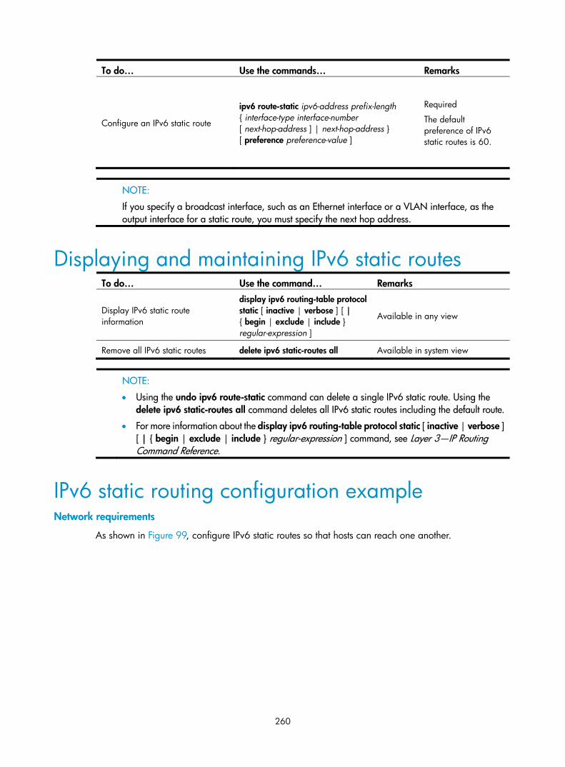
260
To do… Use the commands… Remarks
Configure an IPv6 static route
ipv6 route-static ipv6-address prefix-length { interface-type interface-number [ next-hop-address ] | next-hop-address } [ preference preference-value ]
Required
The default preference of IPv6 static routes is 60.
NOTE:
If you specify a broadcast interface, such as an Ethernet interface or a VLAN interface, as the output interface for a static route, you must specify the next hop address.
Displaying and maintaining IPv6 static routes To do… Use the command… Remarks
Display IPv6 static route information
display ipv6 routing-table protocol static [ inactive | verbose ] [ | { begin | exclude | include } regular-expression ]
Available in any view
Remove all IPv6 static routes delete ipv6 static-routes all Available in system view
NOTE:
• Using the undo ipv6 route-static command can delete a single IPv6 static route. Using the delete ipv6 static-routes all command deletes all IPv6 static routes including the default route.
• For more information about the display ipv6 routing-table protocol static [ inactive | verbose ] [ | { begin | exclude | include } regular-expression ] command, see Layer 3—IP Routing Command Reference.
IPv6 static routing configuration example Network requirements
As shown in Figure 99, configure IPv6 static routes so that hosts can reach one another.

261
Figure 99 Network diagram
Configuration procedure
1. Configure the IPv6 addresses for all VLAN interfaces. (Details not shown)
2. Configure IPv6 static routes.
# Configure a default IPv6 static route on Switch A. <SwitchA> system-view
[SwitchA] ipv6
[SwitchA] ipv6 route-static :: 0 4::2
# Configure two IPv6 static routes on Switch B. <SwitchB> system-view
[SwitchB] ipv6
[SwitchB] ipv6 route-static 1:: 64 4::1
[SwitchB] ipv6 route-static 3:: 64 5::1
# Configure a default IPv6 static route on Switch C. <SwitchC> system-view
[SwitchC] ipv6
[SwitchC] ipv6 route-static :: 0 5::2
3. Configure the IPv6 addresses and gateways for hosts.
Configure the IPv6 addresses for all the hosts based on the network diagram, configure the default gateway of Host A as 1::1, Host B as 2::1, and Host C as 3::1.
4. Verify the configuration.
# Display the IPv6 routing table of Switch A. [SwitchA] display ipv6 routing-table
Routing Table :
Destinations : 5 Routes : 5
Destination : :: Protocol : Static
NextHop : 4::2 Preference : 60
Interface : Vlan-interface200 Cost : 0
Destination : ::1/128 Protocol : Direct
NextHop : ::1 Preference : 0

262
Interface : InLoop0 Cost : 0
Destination : 1::/64 Protocol : Direct
NextHop : 1::1 Preference : 0
Interface : Vlan-interface100 Cost : 0
Destination : 1::1/128 Protocol : Direct
NextHop : ::1 Preference : 0
Interface : InLoop0 Cost : 0
Destination : FE80::/10 Protocol : Direct
NextHop : :: Preference : 0
Interface : NULL0 Cost : 0
# Verify the connectivity with the ping command. [SwitchA] ping ipv6 3::1
PING 3::1 : 56 data bytes, press CTRL_C to break
Reply from 3::1
bytes=56 Sequence=1 hop limit=254 time = 63 ms
Reply from 3::1
bytes=56 Sequence=2 hop limit=254 time = 62 ms
Reply from 3::1
bytes=56 Sequence=3 hop limit=254 time = 62 ms
Reply from 3::1
bytes=56 Sequence=4 hop limit=254 time = 63 ms
Reply from 3::1
bytes=56 Sequence=5 hop limit=254 time = 63 ms
--- 3::1 ping statistics ---
5 packet(s) transmitted
5 packet(s) received
0.00% packet loss
round-trip min/avg/max = 62/62/63 ms

263
RIPng configuration
NOTE:
The term router in this document refers to both routers and Layer 3 switches.
Introduction to RIPng RIP next generation (RIPng) is an extension of RIP-2 for IPv4. Most RIP concepts are applicable in RIPng.
RIPng for IPv6 has the following basic differences from RIP:
• UDP port number—RIPng uses UDP port 521 for sending and receiving routing information
• Multicast address—RIPng uses FF02:9 as the link-local-router multicast address
• Destination Prefix—128-bit destination address prefix
• Next hop—128-bit IPv6 address
• Source address—RIPng uses FE80::/10 as the link-local source address
RIPng working mechanism RIPng is a routing protocol based on the distance vector (D-V) algorithm. RIPng uses UDP packets to exchange routing information through port 521.
RIPng uses a hop count to measure the distance to a destination. The hop count is the metric or cost. The hop count from a router to a directly connected network is 0. The hop count between two directly connected routers is 1. When the hop count is greater than or equal to 16, the destination network or host is unreachable.
By default, the routing update is sent every 30 seconds. If the router receives no routing updates from a neighbor within 180 seconds, the routes learned from the neighbor are considered unreachable. If no routing update is received within another 240 seconds, the router removes these routes from the routing table.
RIPng supports split horizon and poison reverse to prevent routing loops and route redistribution.
Each RIPng router maintains a routing database, which includes route entries of all reachable destinations. A route entry contains the following information:
• Destination address—IPv6 address of a host or a network.
• Next hop address—IPv6 address of a neighbor along the path to the destination
• Egress interface—Outbound interface that forwards IPv6 packets
• Metric—Cost from the local router to the destination
• Route time—Time elapsed since a route entry is last changed. Each time a route entry is modified, the routing time is set to 0.
• Route tag—Identifies the route used in a routing policy to control routing information. For more information about routing policy, see the chapter “Routing policy configuration.”

264
RIPng packet format Basic format
A RIPng packet consists of a header and multiple route table entries (RTEs). The maximum number of RTEs in a packet depends on the IPv6 MTU of the sending interface.
Figure 100 RIPng basic packet format
…
Packet header description:
• Command: Type of message. 0x01 indicates Request; 0x02 indicates Response.
• Version: Version of RIPng. It can only be 0x01.
• RTE: Route table entry. It is 20 bytes for each entry.
RTE format
The following are types of RTEs in RIPng:
• Next hop RTE—Defines the IPv6 address of a next hop
• IPv6 prefix RTE—Describes the destination IPv6 address, route tag, prefix length and metric in the RIPng routing table.
Figure 101 Next hop RTE format
IPv6 next hop address (16 octets)
Must be zero Must be zero 0xFF
0 7 15 31
IPv6 next hop address is the IPv6 address of the next hop.
Figure 102 IPv6 prefix RTE format
IPv6 prefix (16 octets)
Route tag Prefix length Metric
0 7 15 31
IPv6 prefix RTE field description:
• IPv6 prefix—Destination IPv6 address prefix.
• Route tag—Route tag.
• Prefix len—Length of the IPv6 address prefix.
• Metric—Cost of a route.

265
RIPng packet processing procedure Request packet
When a RIPng router first starts or needs to update entries in its routing table, usually a multicast request packet is sent to ask for needed routes from neighbors.
The receiving RIPng router processes RTEs in the request. If only one RTE exists with the IPv6 prefix and prefix length both being 0, and with a metric value of 16, the RIPng router will respond with the entire routing table information in response messages. If multiple RTEs exist in the request message, the RIPng router will examine each RTE, update its metric, and send the requested routing information to the requesting router in the response packet.
Response packet
The response packet containing the local routing table information is generated as follows:
• A response to a request
• An update periodically
• A trigged update caused by route change
After receiving a response, a router checks the validity of the response before adding the route to its routing table, such as whether the source IPv6 address is the link-local address and whether the port number is correct. The response packet that failed the check is discarded.
Protocols and standards • RFC 2080, RIPng for IPv6
• RFC 2081, RIPng Protocol Applicability Statement
RIPng configuration task list Complete the following tasks to configure RIPng:
Task Remarks Configuring RIPng basic functions Required
Configuring RIPng route control
Configuring an additional routing metric Optional
Configuring RIPng route summarization Optional
Advertising a default route Optional
Configuring a RIPng route filtering policy Optional
Configuring a priority for RIPng Optional
Configuring RIPng route redistribution Optional
Tuning and optimizing the RIPng network
Configuring RIPng timers Optional
Configuring split horizon and poison reverse Optional
Configuring zero field check on RIPng packets Optional
Configuring the maximum number of equal cost routes for load balancing Optional
Applying IPsec policies for RIPng Optional

266
Configuring RIPng basic functions This section presents the information to configure the basic RIPng features.
You must enable RIPng first before configuring other tasks, but it is not necessary for RIPng-related interface configurations, such as assigning an IPv6 address.
Configuration prerequisites Before configuring RIPng basic functions, complete the following tasks:
• Enable IPv6 packet forwarding.
• Configure an IP address for each interface, and ensure all nodes are reachable to one another.
Configuration procedure Follow these steps to configure the basic RIPng functions:
To do… Use the command… Remarks Enter system view system-view ––
Create a RIPng process and enter RIPng view
ripng [ process-id ] Required
Not created by default
Return to system view quit —
Enter interface view interface interface-type interface-number ––
Enable RIPng on the interface ripng process-id enable Required
Disabled by default
NOTE:
If RIPng is not enabled on an interface, the interface will not send or receive a RIPng route.
Configuring RIPng route control This section covers the following topics:
• Configuring RIPng route summarization
• Advertising a default route
• Configuring a RIPng route filtering policy
• Configuring a priority for RIPng
• Configuring RIPng route redistribution
Before configuring RIPng, complete the following tasks:
• Configure an IPv6 address on each interface, and ensure all nodes are reachable to one another.
• Configure RIPng basic functions
• Define an IPv6 ACL before using it for route filtering. See ACL and QoS Configuration Guide for related information.

267
• Define an IPv6 address prefix list before using it for route filtering. See the chapter “Routing policy configuration” for related information.
Configuring an additional routing metric An additional routing metric can be added to the metric of an inbound or outbound RIP route.
The outbound additional metric is added to the metric of a sent route. The route’s metric in the routing table is not changed.
The inbound additional metric is added to the metric of a received route before the route is added into the routing table, so the route’s metric is changed.
Follow these steps to configure an inbound or outbound additional routing metric:
To do… Use the command… Remarks Enter system view system-view ––
Enter interface view interface interface-type interface-number ––
Specify an inbound routing additional metric
ripng metricin value Optional
0 by default
Specify an outbound routing additional metric
ripng metricout value Optional
1 by default
Configuring RIPng route summarization Follow these steps to configure RIPng route summarization:
To do… Use the command… Remarks Enter system view system-view ––
Enter interface view interface interface-type interface-number ––
Advertise a summary IPv6 prefix ripng summary-address ipv6-address prefix-length
Required
Advertising a default route Follow these steps to advertise a default route:
To do… Use the command… Remarks Enter system view system-view ––
Enter interface view interface interface-type interface-number ––
Advertise a default route ripng default-route { only | originate } [ cost cost ]
Required
Not advertised by default
NOTE:
With this feature enabled, a default route is advertised through the specified interface regardless of whether the default route is available in the local IPv6 routing table.

268
Configuring a RIPng route filtering policy Reference a configured IPv6 ACL or prefix list to filter received or advertised routing information. You can also filter outbound routes redistributed from a routing specific routing protocol.
Follow these steps to configure a RIPng route filtering policy:
To do… Use the command… Remarks Enter system view system-view ––
Enter RIPng view ripng [ process-id ] ––
Configure a filter policy to filter incoming routes
filter-policy { acl6-number | ipv6-prefix ipv6-prefix-name } import
Required
By default, RIPng does not filter incoming routing information.
Configure a filter policy to filter outgoing routes
filter-policy { acl6-number | ipv6-prefix ipv6-prefix-name } export [ protocol [ process-id ] ]
Required
By default, RIPng does not filter outgoing routing information.
Configuring a priority for RIPng Any routing protocol has its own protocol priority used for optimal route selection. You can set a priority for RIPng manually. The smaller the value, the higher the priority.
Follow these steps to configure a RIPng priority:
To do… Use the command… Remarks Enter system view system-view —
Enter RIPng view ripng [ process-id ] —
Configure a RIPng priority preference [ route-policy route-policy-name ] preference
Optional
By default, the RIPng priority is 100.
Configuring RIPng route redistribution Follow these steps to configure RIPng route redistribution:
To do… Use the command… Remarks Enter system view system-view ––
Enter RIPng view ripng [ process-id ] ––
Configure a default routing metric for redistributed routes default cost cost
Optional
The default metric of redistributed routes is 0.
Redistribute routes from another routing protocol
import-route protocol [ process-id ] [ allow-ibgp ] [ cost cost | route-policy route-policy-name ] *
Required
No route redistribution is configured by default.

269
Tuning and optimizing the RIPng network This section describes how to tune and optimize the performance of the RIPng network, as well as applications under special network environments. Before tuning and optimizing the RIPng network, complete the following tasks:
• Configure a network layer address for each interface
• Configure the basic RIPng functions
Configuring RIPng timers Adjust RIPng timers to optimize the performance of the RIPng network.
Follow these steps to configure RIPng timers:
To do… Use the command… Remarks Enter system view system-view —
Enter RIPng view ripng [ process-id ] —
Configure RIPng timers
timers { garbage-collect garbage-collect-value | suppress suppress-value | timeout timeout-value | update update-value } *
Optional.
The RIPng timers have the following defaults: • 30 seconds for the update timer • 180 seconds for the timeout timer • 120 seconds for the suppress timer • 120 seconds for the garbage-collect timer
NOTE:
When adjusting RIPng timers, consider the network performance, and perform unified configurations onrouters running RIPng to avoid unnecessary network traffic increase or route oscillation.
Configuring split horizon and poison reverse
NOTE:
If both split horizon and poison reverse are configured, only the poison reverse function takes effect.
Configure split horizon
The split horizon function disables a route learned from an interface from being advertised through the same interface to prevent routing loops between neighbors.
Follow these steps to configure split horizon:
To do… Use the command… Remarks Enter system view system-view ––
Enter interface view interface interface-type interface-number ––
Enable the split horizon function ripng split-horizon Optional
Enabled by default

270
NOTE:
HP recommends enabling split horizon to prevent routing loops.
Configuring the poison reverse function
The poison reverse function enables a route learned from an interface to be advertised through the interface. However, the metric of the route is set to 16 (unreachable).
Follow these steps to configure poison reverse:
To do… Use the command… Remarks Enter system view system-view ––
Enter interface view interface interface-type interface-number ––
Enable the poison reverse function ripng poison-reverse Required
Disabled by default
Configuring zero field check on RIPng packets Some fields in the RIPng packet must be zero, which are called “zero fields”. With zero field check on RIPng packets enabled, if such a field contains a non-zero value, the entire RIPng packet is discarded. If you are sure that all packets are trustworthy, disable the zero field check to reduce the CPU processing time.
Follow these steps to configure RIPng zero field check:
To do… Use the command… Remarks Enter system view system-view ––
Enter RIPng view ripng [ process-id ] ––
Enable the zero field check checkzero Optional
Enabled by default
Configuring the maximum number of equal cost routes for load balancing
Follow these steps to configure the maximum number of equal cost RIPng routes for load balancing:
To do… Use the command… Remarks Enter system view system-view ––
Enter RIPng view ripng [ process-id ] ––
Configure the maximum number of equal cost RIPng routes for load balancing
maximum load-balancing numberOptional
8 by default

271
Applying IPsec policies for RIPng To protect routing information and defend attacks, RIPng supports using an IPsec policy to authenticate protocol packets.
Outbound RIPng packets carry the Security Parameter Index (SPI) defined in the relevant IPsec policy. A device uses the SPI carried in a received packet to match against the configured IPsec policy. If they match, the device accepts the packet; otherwise, it discards the packet and will not establish a neighbor relationship with the sending device.
You can configure an IPsec policy for a RIPng process or interface. The IPsec policy configured for a process applies to all packets in the process. The IPsec policy configured on an interface applies to packets on the interface. If an interface and its process each have an IPsec policy configured, the interface uses its own IPsec policy.
Configuration prerequisites
Before applying an IPsec policy for RIPng, complete following tasks:
• Create an IPsec proposal
• Create an IPsec policy
For more information about IPsec policy configuration, see Security Configuration Guide.
Configuration procedure
Follow these steps to apply an IPsec policy in a process:
To do… Use the command… Remarks Enter system view system-view —
Enter RIPng view ripng [ process-id ] —
Apply an IPsec policy in the process enable ipsec-policy policy-name Required
Not configured by default
Follow these steps to apply an IPsec policy on an interface:
To do… Use the command… Remarks Enter system view system-view —
Enter interface view interface interface-type interface-number
—
Apply an IPsec policy on the interface ripng ipsec-policy policy-name
Required
Not configured by default
NOTE:
An IPsec policy used for RIPng can only be in manual mode. For more information, see Security Configuration Guide.

272
Displaying and maintaining RIPng To do… Use the command… Remarks
Display configuration information of a RIPng process
display ripng [ process-id ] [ | { begin | exclude | include } regular-expression ]
Available in any view
Display routes in the RIPng database
display ripng process-id database [ | { begin | exclude | include } regular-expression ]
Available in any view
Display the routing information of a specified RIPng process
display ripng process-id route [ | { begin | exclude | include } regular-expression ]
Available in any view
Display RIPng interface information
display ripng process-id interface [ interface-type interface-number ] [ | { begin | exclude | include } regular-expression ]
Available in any view
Reset a RIPng process reset ripng process-id process Available in user view
Clear statistics of a RIPng process reset ripng process-id statistics Available in user view
RIPng configuration examples
Configuring RIPng basic functions Network requirements
In Figure 103, all switches run RIPng. Configure Switch B to filter the route (3::/64) learned from Switch C, which means the route will not be added to the routing table of Switch B, and Switch B will not forward it to Switch A.
Figure 103 Network diagram
Configuration procedure
1. Configure the IPv6 address for each interface. (Details not shown)
2. Configure basic RIPng functions.
# Configure Switch A. <SwitchA> system-view
[SwitchA] ripng 1
[SwitchA-ripng-1] quit
[SwitchA] interface vlan-interface 100
[SwitchA-Vlan-interface100] ripng 1 enable
[SwitchA-Vlan-interface100] quit

273
[SwitchA] interface vlan-interface 400
[SwitchA-Vlan-interface400] ripng 1 enable
[SwitchA-Vlan-interface400] quit
# Configure Switch B. <SwitchB> system-view
[SwitchB] ripng 1
[SwitchB-ripng-1] quit
[SwitchB] interface vlan-interface 200
[SwitchB-Vlan-interface200] ripng 1 enable
[SwitchB-Vlan-interface200] quit
[SwitchB] interface vlan-interface 100
[SwitchB-Vlan-interface100] ripng 1 enable
[SwitchB-Vlan-interface100] quit
# Configure Switch C. <SwitchC> system-view
[SwitchC] ripng 1
[SwitchC-ripng-1] quit
[SwitchC] interface vlan-interface 200
[SwitchC-Vlan-interface200] ripng 1 enable
[SwitchC-Vlan-interface200] quit
[SwitchC] interface vlan-interface 500
[SwitchC-Vlan-interface500] ripng 1 enable
[SwitchC-Vlan-interface500] quit
[SwitchC] interface vlan-interface 600
[SwitchC-Vlan-interface600] ripng 1 enable
[SwitchC-Vlan-interface600] quit
# Display the routing table of Switch B. [SwitchB] display ripng 1 route
Route Flags: A - Aging, S - Suppressed, G - Garbage-collect
----------------------------------------------------------------
Peer FE80::20F:E2FF:FE23:82F5 on Vlan-interface100
Dest 1::/64,
via FE80::20F:E2FF:FE23:82F5, cost 1, tag 0, A, 6 Sec
Dest 2::/64,
via FE80::20F:E2FF:FE23:82F5, cost 1, tag 0, A, 6 Sec
Peer FE80::20F:E2FF:FE00:100 on Vlan-interface200
Dest 3::/64,
via FE80::20F:E2FF:FE00:100, cost 1, tag 0, A, 11 Sec
Dest 4::/64,
via FE80::20F:E2FF:FE00:100, cost 1, tag 0, A, 11 Sec
Dest 5::/64,
via FE80::20F:E2FF:FE00:100, cost 1, tag 0, A, 11 Sec
# Display the routing table of Switch A. [SwitchA] display ripng 1 route
Route Flags: A - Aging, S - Suppressed, G - Garbage-collect

274
----------------------------------------------------------------
Peer FE80::200:2FF:FE64:8904 on Vlan-interface100
Dest 1::/64,
via FE80::200:2FF:FE64:8904, cost 1, tag 0, A, 31 Sec
Dest 4::/64,
via FE80::200:2FF:FE64:8904, cost 2, tag 0, A, 31 Sec
Dest 5::/64,
via FE80::200:2FF:FE64:8904, cost 2, tag 0, A, 31 Sec
Dest 3::/64,
via FE80::200:2FF:FE64:8904, cost 1, tag 0, A, 31 Sec
3. Configure Switch B to filter incoming and outgoing routes. [SwitchB] acl ipv6 number 2000
[SwitchB-acl6-basic-2000] rule deny source 3::/64
[SwitchB-acl6-basic-2000] rule permit
[SwitchB-acl6-basic-2000] quit
[SwitchB] ripng 1
[SwitchB-ripng-1] filter-policy 2000 import
[SwitchB-ripng-1] filter-policy 2000 export
# Display routing tables of Switch B and Switch A. [SwitchB] display ripng 1 route
Route Flags: A - Aging, S - Suppressed, G - Garbage-collect
----------------------------------------------------------------
Peer FE80::20F:E2FF:FE23:82F5 on Vlan-interface100
Dest 1::/64,
via FE80::20F:E2FF:FE23:82F5, cost 1, tag 0, A, 2 Sec
Dest 2::/64,
via FE80::20F:E2FF:FE23:82F5, cost 1, tag 0, A, 2 Sec
Peer FE80::20F:E2FF:FE00:100 on Vlan-interface200
Dest 4::/64,
via FE80::20F:E2FF:FE00:100, cost 1, tag 0, A, 5 Sec
Dest 5::/64,
via FE80::20F:E2FF:FE00:100, cost 1, tag 0, A, 5 Sec
[SwitchA] display ripng 1 route
Route Flags: A - Aging, S - Suppressed, G - Garbage-collect
----------------------------------------------------------------
Peer FE80::20F:E2FF:FE00:1235 on Vlan-interface100
Dest 1::/64,
via FE80::20F:E2FF:FE00:1235, cost 1, tag 0, A, 2 Sec
Dest 4::/64,
via FE80::20F:E2FF:FE00:1235, cost 2, tag 0, A, 2 Sec
Dest 5::/64,
via FE80::20F:E2FF:FE00:1235, cost 2, tag 0, A, 2 Sec

275
Configuring RIPng route redistribution Network requirements
Two RIPng processes are running on Switch B, which communicates with Switch A through RIPng 100 and with Switch C through RIPng 200.
Configure route redistribution on Switch B, letting the two RIPng processes redistribute routes from each other. Set the default cost of redistributed routes from RIPng 200 to 3.
Figure 104 Network diagram
Configuration procedure
1. Configure IPv6 addresses for the interfaces. (Details not shown)
2. Configure RIPng basic functions.
# Enable RIPng 100 on Switch A. <SwitchA> system-view
[SwitchA] ripng 100
[SwitchA-ripng-100] quit
[SwitchA] interface vlan-interface 100
[SwitchA-Vlan-interface100] ripng 100 enable
[SwitchA-Vlan-interface100] quit
[SwitchA] interface vlan-interface 200
[SwitchA-Vlan-interface200] ripng 100 enable
[SwitchA-Vlan-interface200] quit
# Enable RIP 100 and RIP 200 on Switch B. <SwitchB> system-view
[SwitchB] ripng 100
[SwitchB-ripng-100] quit
[SwitchB] interface vlan-interface 100
[SwitchB-Vlan-interface100] ripng 100 enable
[SwitchB-Vlan-interface100] quit
[SwitchB] ripng 200
[SwitchB-ripng-200] quit
[SwitchB] interface vlan-interface 300
[SwitchB-Vlan-interface300] ripng 200 enable
[SwitchB-Vlan-interface300] quit
# Enable RIPng 200 on Switch C. <SwitchC> system-view
[SwitchC] ripng 200
[SwitchC] interface vlan-interface 300
[SwitchC-Vlan-interface300] ripng 200 enable

276
[SwitchC-Vlan-interface300] quit
[SwitchC] interface vlan-interface 400
[SwitchC-Vlan-interface400] ripng 200 enable
[SwitchC-Vlan-interface400] quit
# Display the routing table of Switch A. [SwitchA] display ipv6 routing-table
Routing Table :
Destinations : 6 Routes : 6
Destination: ::1/128 Protocol : Direct
NextHop : ::1 Preference: 0
Interface : InLoop0 Cost : 0
Destination: 1::/64 Protocol : Direct
NextHop : 1::1 Preference: 0
Interface : Vlan100 Cost : 0
Destination: 1::1/128 Protocol : Direct
NextHop : ::1 Preference: 0
Interface : InLoop0 Cost : 0
Destination: 2::/64 Protocol : Direct
NextHop : 2::1 Preference: 0
Interface : Vlan200 Cost : 0
Destination: 2::1/128 Protocol : Direct
NextHop : ::1 Preference: 0
Interface : InLoop0 Cost : 0
Destination: FE80::/10 Protocol : Direct
NextHop : :: Preference: 0
Interface : NULL0 Cost : 0
3. Configure RIPng route redistribution
# Configure route redistribution between the two RIPng processes on Switch B. [SwitchB] ripng 100
[SwitchB-ripng-100] default cost 3
[SwitchB-ripng-100] import-route ripng 200
[SwitchB-ripng-100] quit
[SwitchB] ripng 200
[SwitchB-ripng-200] import-route ripng 100
[SwitchB-ripng-200] quit
# Display the routing table of Switch A. [SwitchA] display ipv6 routing-table
Routing Table :
Destinations : 7 Routes : 7
Destination: ::1/128 Protocol : Direct

277
NextHop : ::1 Preference: 0
Interface : InLoop0 Cost : 0
Destination: 1::/64 Protocol : Direct
NextHop : 1::1 Preference: 0
Interface : Vlan100 Cost : 0
Destination: 1::1/128 Protocol : Direct
NextHop : ::1 Preference: 0
Interface : InLoop0 Cost : 0
Destination: 2::/64 Protocol : Direct
NextHop : 2::1 Preference: 0
Interface : Vlan200 Cost : 0
Destination: 2::1/128 Protocol : Direct
NextHop : ::1 Preference: 0
Interface : InLoop0 Cost : 0
Destination: 4::/64 Protocol : RIPng
NextHop : FE80::200:BFF:FE01:1C02 Preference: 100
Interface : Vlan100 Cost : 4
Destination: FE80::/10 Protocol : Direct
NextHop : :: Preference: 0
Interface : NULL0 Cost : 0d
Configuring RIPng IPsec policies Network requirements
In the following figure, configure RIPng on the switches, and configure IPsec policies on the switches to authenticate and encrypt protocol packets.
Figure 105 Network diagram
Configuration procedure
1. Configure IPv6 addresses for interfaces. (Details not shown)
2. Configure RIPng basic functions
# Configure Switch A. <SwitchA> system-view
[SwitchA] ripng 1
[SwitchA-ripng-1] quit
[SwitchA] interface vlan-interface 100
[SwitchA-Vlan-interface100] ripng 1 enable

278
[SwitchA-Vlan-interface100] quit
# Configure Switch B. <SwitchB> system-view
[SwitchB] ripng 1
[SwitchB-ripng-1] quit
[SwitchB] interface vlan-interface 200
[SwitchB-Vlan-interface200] ripng 1 enable
[SwitchB-Vlan-interface200] quit
[SwitchB] interface vlan-interface 100
[SwitchB-Vlan-interface100] ripng 1 enable
[SwitchB-Vlan-interface100] quit
# Configure Switch C. <SwitchC> system-view
[SwitchC] ripng 1
[SwitchC-ripng-1] quit
[SwitchC] interface vlan-interface 200
[SwitchC-Vlan-interface200] ripng 1 enable
[SwitchC-Vlan-interface200] quit
3. Configure RIPng IPsec policies
# On Switch A, create an IPsec proposal named tran1, and set the encapsulation mode to transport mode, the security protocol to ESP, the encryption algorithm to DES, and authentication algorithm to SHA1; create an IPsec policy named policy001, specify the manual mode for it, reference IPsec proposal tran1, set the SPIs of the inbound and outbound SAs to 12345, and the keys for the inbound and outbound SAs using ESP to abcdefg. [SwitchA] ipsec proposal tran1
[SwitchA-ipsec-proposal-tran1] encapsulation-mode transport
[SwitchA-ipsec-proposal-tran1] transform esp
[SwitchA-ipsec-proposal-tran1] esp encryption-algorithm des
[SwitchA-ipsec-proposal-tran1] esp authentication-algorithm sha1
[SwitchA-ipsec-proposal-tran1] quit
[SwitchA] ipsec policy policy001 10 manual
[SwitchA-ipsec-policy-manual-policy001-10] proposal tran1
[SwitchA-ipsec-policy-manual-policy001-10] sa spi outbound esp 12345
[SwitchA-ipsec-policy-manual-policy001-10] sa spi inbound esp 12345
[SwitchA-ipsec-policy-manual-policy001-10] sa string-key outbound esp abcdefg
[SwitchA-ipsec-policy-manual-policy001-10] sa string-key inbound esp abcdefg
[SwitchA-ipsec-policy-manual-policy001-10] quit
# On Switch B, create an IPsec proposal named tran1, and set the encapsulation mode to transport mode, the security protocol to ESP, the encryption algorithm to DES, and authentication algorithm to SHA1; create an IPsec policy named policy001, specify the manual mode for it, reference IPsec proposal tran1, set the SPIs of the inbound and outbound SAs to 12345, and the keys for the inbound and outbound SAs using ESP to abcdefg. [SwitchB] ipsec proposal tran1
[SwitchB-ipsec-proposal-tran1] encapsulation-mode transport
[SwitchB-ipsec-proposal-tran1] transform esp
[SwitchB-ipsec-proposal-tran1] esp encryption-algorithm des
[SwitchB-ipsec-proposal-tran1] esp authentication-algorithm sha1

279
[SwitchB-ipsec-proposal-tran1] quit
[SwitchB] ipsec policy policy001 10 manual
[SwitchB-ipsec-policy-manual-policy001-10] proposal tran1
[SwitchB-ipsec-policy-manual-policy001-10] sa spi outbound esp 12345
[SwitchB-ipsec-policy-manual-policy001-10] sa spi inbound esp 12345
[SwitchB-ipsec-policy-manual-policy001-10] sa string-key outbound esp abcdefg
[SwitchB-ipsec-policy-manual-policy001-10] sa string-key inbound esp abcdefg
[SwitchB-ipsec-policy-manual-policy001-10] quit
# On Switch C, create an IPsec proposal named tran1, and set the encapsulation mode to transport mode, the security protocol to ESP, the encryption algorithm to DES, and authentication algorithm to SHA1; create an IPsec policy named policy001, specify the manual mode for it, reference IPsec proposal tran1, set the SPIs of the inbound and outbound SAs to 12345, and the keys for the inbound and outbound SAs using ESP to abcdefg. [SwitchC] ipsec proposal tran1
[SwitchC-ipsec-proposal-tran1] encapsulation-mode transport
[SwitchC-ipsec-proposal-tran1] transform esp
[SwitchC-ipsec-proposal-tran1] esp encryption-algorithm des
[SwitchC-ipsec-proposal-tran1] esp authentication-algorithm sha1
[SwitchC-ipsec-proposal-tran1] quit
[SwitchC] ipsec policy policy001 10 manual
[SwitchC-ipsec-policy-manual-policy001-10] proposal tran1
[SwitchC-ipsec-policy-manual-policy001-10] sa spi outbound esp 12345
[SwitchC-ipsec-policy-manual-policy001-10] sa spi inbound esp 12345
[SwitchC-ipsec-policy-manual-policy001-10] sa string-key outbound esp abcdefg
[SwitchC-ipsec-policy-manual-policy001-10] sa string-key inbound esp abcdefg
[SwitchC-ipsec-policy-manual-policy001-10] quit
4. Apply the IPsec policies in the RIPng process
# Configure Switch A. [SwitchA] ripng 1
[SwitchA-ripng-1] enable ipsec-policy policy001
[SwitchA-ripng-1] quit
# Configure Switch B. [SwitchB] ripng 1
[SwitchB-ripng-1] enable ipsec-policy policy001
[SwitchB-ripng-1] quit
# Configure Switch C. [SwitchC] ripng 1
[SwitchC-ripng-1] enable ipsec-policy policy001
[SwitchC-ripng-1] quit
5. Verify the configuration.
RIPng traffic between Switches A, B and C is protected by IPsec.

280
OSPFv3 configuration
NOTE:
• The term router in this document refers to both routers and Layer 3 switches.
• The 3600 v2 SI Switch Series does not support OSPFv3.
Introduction to OSPFv3
OSPFv3 overview Open Shortest Path First version 3 (OSPFv3) supports IPv6 and complies with RFC 2740 (OSPF for IPv6).
OSPFv3 and OSPFv2 have the following similarities:
• 32-bits router ID and area ID
• Packets—Hello, DD (Data Description), LSR (Link State Request), LSU (Link State Update), and LSAck (Link State Acknowledgment)
• Mechanism for finding neighbors and establishing adjacencies
• Mechanism for LSA flooding and aging
OSPFv3 and OSPFv2 have the following differences:
• OSPFv3 runs on a per-link basis, and OSPFv2 runs on a per-IP-subnet basis.
• OSPFv3 supports multiple instances per link, but OSPFv2 does not.
• OSPFv3 identifies neighbors by Router ID, and OSPFv2 by IP address.
OSPFv3 packets OSPFv3 has the following packet types: hello, DD, LSR, LSU, and LSAck. These packets have the same packet header, which is different from the OSPFv2 packet header. The OSPFv3 packet header is only 16 bytes in length, has no authentication field, and is added with an Instance ID field to support multi-instance per link.
Figure 106 OSPFv3 packet header
Major fields for OSPFv3 packets are as follows:
• Version #—Version of OSPF, which is 3 for OSPFv3.
• Type—Type of OSPF packet; types 1 to 5 are hello, DD, LSR, LSU, and LSAck respectively.

281
• Packet length—Packet length in bytes, including header.
• Instance ID—Instance ID for a link.
• 0—Reserved. It must be 0.
OSPFv3 LSA types OSPFv3 sends routing information in LSAs, which, as defined in RFC 2740, have the following types:
• Router-LSA—Originated by all routers. This LSA describes the collected states of the router's interfaces to an area, and is flooded throughout a single area only.
• Network-LSA—Originated for broadcast and NBMA networks by the Designated Router. This LSA contains the list of routers connected to the network, and is flooded throughout a single area only.
• Inter-Area-Prefix-LSA—Similar to Type 3 LSA of OSPFv2, originated by ABRs (Area Border Routers), and flooded throughout the LSA's associated area. Each Inter-Area-Prefix-LSA describes a route with IPv6 address prefix to a destination outside the area, yet still inside the AS (an inter-area route).
• Inter-Area-Router-LSA—Similar to Type 4 LSA of OSPFv2, originated by ABRs and flooded throughout the LSA's associated area. Each Inter-Area-Router-LSA describes a route to ASBR (Autonomous System Boundary Router).
• AS-external-LSA—Originated by ASBRs, and flooded throughout the AS (except Stub and NSSA areas). Each AS-external-LSA describes a route to another autonomous system. A default route can be described by an AS-external-LSA.
• Link-LSA—A router originates a separate Link-LSA for each attached link. Link-LSAs have link-local flooding scope. Each Link-LSA describes the IPv6 address prefix of the link and Link-local address of the router.
• Intra-Area-Prefix-LSA—Each Intra-Area-Prefix-LSA contains IPv6 prefix information on a router, stub area, or transit area information, and has area flooding scope. It was introduced because Router-LSAs and Network-LSAs do not contain address information.
RFC 5187 defines the Type 11 LSA, Grace-LSA. A Grace-LSA is generated by a GR (Graceful Restart) Restarter at reboot and transmitted on the local link. The restarter describes the cause and interval of the reboot in the Grace-LSA to tell its neighbors that it performs a GR operation.
Timers of OSPFv3 Timers in OSPFv3 include the following:
• OSPFv3 packet timer
• LSA delay timer
• SPF timer
• GR timer
OSPFv3 packet timer
Hello packets are sent periodically between neighboring routers for finding and maintaining neighbor relationships, or for DR or BDR election. The hello interval must be identical on neighboring interfaces. The smaller the hello interval, the faster the network convergence speed and the bigger the network load.
If a router does not receive a hello packet from a neighbor within a given period—dead interval, it then declares the peer down.

282
After sending an LSA to its adjacency, a router waits for an acknowledgment from the adjacency. If no response is received after the retransmission interval elapses, the router will send the LSA again. The retransmission interval must be longer than the round-trip time of the LSA.
LSA delay time
Each LSA has an age in the local LSDB (incremented by one per second), but an LSA does not age on transmission. You must add an LSA delay time into the age time before transmission, which is important for low-speed networks.
SPF timer
Whenever the LSDB changes, an SPF calculation occurs. If recalculations become frequent, a large amount of resources will be occupied. You can adjust the SPF calculation interval and delay time to protect networks from being overloaded by frequent changes.
GR timer
If a failure to establish adjacencies occurs during a GR, the device will be in the GR process for a long time. To avoid this, configure the GR timer for the device to exit the GR process when the timer expires.
OSPFv3 features supported • Basic features defined in RFC 2740
• OSPFv3 stub area
• OSPFv3 multi-process
• VPN instances
• OSPFv3 GR
• BFD
Protocols and standards • RFC 2740, OSPF for IPv6
• RFC 2328, OSPF Version 2
• RFC 5187, OSPFv3 Graceful Restart
OSPFv3 configuration task list Complete the following tasks to configure OSPFv3:
Task Remarks Enabling OSPFv3 Required
Configuring OSPFv3 area parameters
Configuring an OSPFv3 stub area Optional
Configuring an OSPFv3 virtual link Optional
Configuring OSPFv3 network types
Configuring the OSPFv3 network type for an interface Optional
Configuring an NBMA or P2MP neighbor Optional
Configuring OSPFv3 routing information control
Configuring OSPFv3 route summarization Optional
Configuring OSPFv3 inbound route filtering Optional

283
Task Remarks Configuring an OSPFv3 cost for an interface Optional
Configuring the maximum number of OSPFv3 load-balanced routes Optional
Configuring a priority for OSPFv3 Optional
Configuring OSPFv3 route redistribution Optional
Tuning and optimizing OSPFv3 networks
Configuring OSPFv3 timers Optional
Configuring a DR priority for an interface Optional
Ignoring MTU check for DD packets Optional
Disable interfaces from receiving and sending OSPFv3 packets Optional
Enable the logging of neighbor state changes Optional
Configuring OSPFv3 GR Configuring GR Restarter Optional
Configuring GR Helper Optional
Configuring BFD for OSPFv3 Optional
Applying IPsec policies for OSPFv3 Optional
Enabling OSPFv3
Configuration prerequisites Before enabling OSPFv3, complete the following tasks:
• Make neighboring nodes accessible with each other at the network layer
• Enable IPv6 packet forwarding
Enabling OSPFv3 To enable an OSPFv3 process on a router, you must enable the OSPFv3 process globally, assign the OSPFv3 process a router ID, and enable the OSPFv3 process on related interfaces.
A router ID uniquely identifies a router within an AS. You must specify a unique router ID for each OSPFv3 router within the AS to ensure normal operation. If a router runs multiple OSPFv3 processes, you must specify a unique router ID for each process.
An OSPFv3 process ID has only local significance. Process 1 on a router can exchange packets with process 2 on another router.
Follow these steps to enable OSPFv3:
To do… Use the command… Remarks Enter system view system-view —
Enable an OSPFv3 process and enter its view ospfv3 [ process-id ]
Required
By default, no OSPFv3 process is enabled.
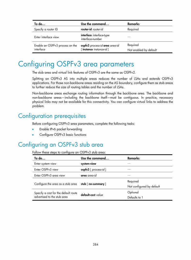
284
To do… Use the command… Remarks Specify a router ID router-id router-id Required
Enter interface view interface interface-type interface-number
—
Enable an OSPFv3 process on the interface
ospfv3 process-id area area-id [ instance instance-id ]
Required
Not enabled by default
Configuring OSPFv3 area parameters The stub area and virtual link features of OSPFv3 are the same as OSPFv2.
Splitting an OSPFv3 AS into multiple areas reduces the number of LSAs and extends OSPFv3 applications. For those non-backbone areas residing on the AS boundary, configure them as stub areas to further reduce the size of routing tables and the number of LSAs.
Non-backbone areas exchange routing information through the backbone area. The backbone and non-backbone areas—including the backbone itself—must be contiguous. In practice, necessary physical links may not be available for this connectivity. You can configure virtual links to address the problem.
Configuration prerequisites Before configuring OSPFv3 area parameters, complete the following tasks:
• Enable IPv6 packet forwarding
• Configure OSPFv3 basic functions
Configuring an OSPFv3 stub area Follow these steps to configure an OSPFv3 stub area:
To do… Use the command… Remarks Enter system view system-view —
Enter OSPFv3 view ospfv3 [ process-id ] —
Enter OSPFv3 area view area area-id —
Configure the area as a stub area stub [ no-summary ] Required
Not configured by default
Specify a cost for the default route advertised to the stub area default-cost value
Optional
Defaults to 1

285
NOTE:
• You cannot remove an OSPFv3 area directly. The area can be removed only when you remove all configurations in area view and all interfaces attached to the area become down.
• All the routers attached to a stub area must be configured with the stub command. The keyword no-summary is only available on the ABR of the stub area.
• If you use the stub command with the keyword no-summary on an ABR, the ABR advertises a default route in an Inter-Area-Prefix-LSA into the stub area. No AS-external-LSA, Inter-Area-Prefix-LSA, or Inter-Area-Router-LSA is advertised in the area. The stub area of this kind is also known as a “totally stubarea.”
Configuring an OSPFv3 virtual link You can configure a virtual link to maintain connectivity between a non-backbone area and the backbone, or in the backbone itself.
Follow these steps to configure a virtual link:
To do… Use the command… Remarks Enter system view system-view —
Enter OSPFv3 view ospfv3 [ process-id ] —
Enter OSPFv3 area view area area-id —
Configure a virtual link vlink-peer router-id [ hello seconds | retransmit seconds | trans-delay seconds | dead seconds | instance instance-id ] *
Required
NOTE:
• Both ends of a virtual link are ABRs that must be configured with the vlink-peer command.
• Do not configure virtual links in the areas of a GR-capable process.
Configuring OSPFv3 network types OSPFv3 classifies networks into the following types by the link layer protocol.
By default, the default OSPFv3 interface network types vary with the link layer protocols of the interfaces:
• When the link layer protocol is PPP, OSPFv3 considers the network type as P2P by default.
• When the link layer protocol is Ethernet, OSPFv3 considers the network type as broadcast by default.
You can change the network type of an OSPFv3 interface as needed. For example:
• An NBMA network must be fully connected. Any two routers in the network must be directly reachable to each other through a virtual circuit. If no such direct link is available, you must change the network type through a command.
• If direct connections are not available between some routers in an NBMA network, the type of interfaces associated must be configured as P2MP, or as P2P for interfaces with only one neighbor.

286
Configuration prerequisites Before configuring OSPFv3 network types, complete the following tasks:
• Configure IPv6 functions
• Configure OSPFv3 basic functions
Configuring the OSPFv3 network type for an interface Follow these steps to configure the OSPFv3 network type for an interface:
To do… Use the command… Remarks Enter system view system-view —
Enter interface view interface interface-type interface-number
—
Configure a network type for the OSPFv3 interface
ospfv3 network-type { broadcast | nbma | p2mp [ non-broadcast ] | p2p } [ instance instance-id ]
Optional
The network type of an interface depends on the media type of the interface.
Configuring an NBMA or P2MP neighbor For NBMA and P2MP interfaces (only when in unicast mode), specify the link-local IP addresses of their neighbors because these interfaces cannot find neighbors through broadcasting hello packets. You can also specify DR priorities for neighbors.
Follow these steps to configure an NBMA or P2MP (unicast) neighbor and its DR priority:
To do… Use the command… Remarks Enter system view system-view —
Enter interface view interface interface-type interface-number
—
Specify an NBMA or P2MP (unicast) neighbor and its DR priority
ospfv3 peer ipv6-address [ dr-priority dr-priority ] [ instance instance-id ]
Required
Configuring OSPFv3 routing information control This section describes how to configure the control of OSPF routing information advertisement and reception, and redistribution from other protocols.
Configuration prerequisites Before configuring OSPFv3 routing information control, complete the following tasks:
• Enable IPv6 packet forwarding
• Configure OSPFv3 basic functions

287
Configuring OSPFv3 route summarization If contiguous network segments exist in an area, use the abr-summary command to summarize them into one network segment on the ABR. The ABR will advertise only the summary route. Any LSA in the specified network segment will not be advertised, reducing the LSDB size in other areas.
Follow these steps to configure route summarization:
To do… Use the command… Remarks Enter system view system-view —
Enter OSPFv3 view ospfv3 [ process-id ] —
Enter OSPFv3 area view area area-id —
Configure a summary route abr-summary ipv6-address prefix-length [ not-advertise ]
Required
Not configured by default
NOTE:
The abr-summary command takes effect on ABRs only.
Configuring OSPFv3 inbound route filtering According to some rules, you can configure OSPFv3 to filter routes that are computed from received LSAs.
Follow these steps to configure OSPFv3 inbound route filtering:
To do… Use the command… Remarks Enter system view system-view —
Enter OSPFv3 view ospfv3 [ process-id ] —
Configure inbound route filtering
filter-policy { acl-number | ipv6-prefix ipv6-prefix-name } import
Required
Not configured by default
NOTE:
Using the filter-policy import command can only filter routes computed by OSPFv3. Only routes not filtered out can be added into the local routing table.
Configuring an OSPFv3 cost for an interface You can configure an OSPFv3 cost for an interface with one of the following methods:
• Configure the cost value in interface view
• Configure a bandwidth reference value for the interface, and OSPFv3 computes the cost automatically based on the bandwidth reference value: Interface OSPFv3 cost = Bandwidth reference value (100 Mbps) ÷ Interface bandwidth (Mbps). If the calculated cost is greater than 65535, the value of 65535 is used; if the calculated cost is smaller than 1, the value of 1 is used.
If the cost value is not configured for an interface, OSPFv3 computes the interface cost value automatically.
Follow these steps to configure an OSPFv3 cost for an interface:

288
To do… Use the command… Remarks Enter system view system-view —
Enter interface view interface interface-type interface-number
—
Configure an OSPFv3 cost for the interface
ospfv3 cost value [ instance instance-id ]
Optional
The default cost depends on the interface type: 1 for a VLAN interface; 0 for a loopback interface; computed according to the bandwidth for other interfaces.
Follow these steps to configure a bandwidth reference value:
To do… Use the command… Remarks Enter system view system-view —
Enter OSPFv3 view ospfv3 [ process-id ] —
Configure a bandwidth reference value
bandwidth-reference value Optional
100 Mbps by default
Configuring the maximum number of OSPFv3 load-balanced routes
If multiple equal-cost routes to a destination are available, enabling load balancing among these routes can improve link utilization.
Follow these steps to configure the maximum number of load-balanced routes:
To do… Use the command… Remarks Enter system view system-view —
Enter OSPFv3 view ospfv3 [ process-id ] —
Specify the maximum number of load-balanced routes
maximum load-balancing maximum
Optional
8 by default
Configuring a priority for OSPFv3 A router may run multiple routing protocols. The system assigns a priority for each protocol. When these routing protocols find the same route, the route found by the protocol with the highest priority is selected.
Follow these steps to configure a priority for OSPFv3:
To do… Use the command… Remarks Enter system view system-view —
Enter OSPFv3 view ospfv3 [ process-id ] —
Configure a priority for OSPFv3
preference [ ase ] [ route-policy route-policy-name ] preference
Optional
By default, the priority of OSPFv3 internal routes is 10, and priority of OSPFv3 external routes is 150.

289
Configuring OSPFv3 route redistribution Follow these steps to configure OSPFv3 route redistribution:
To do… Use the command… Remarks Enter system view system-view —
Enter OSPFv3 view ospfv3 [ process-id ] —
Specify a default cost for redistributed routes
default cost value Optional
Defaults to 1
Redistribute routes from another protocol, or another OSPFv3 process
import-route protocol [ process-id | allow-ibgp ] [ cost value | route-policy route-policy-name | type type ] *
Required
Not configured by default
Inject a default route default-route-advertise [ always | cost value | type type | route-policy route-policy-name ] *
Optional
Not injected by default
Filter redistributed routes
filter-policy { acl6-number | ipv6-prefix ipv6-prefix-name } export [ isisv6 process-id | ospfv3 process-id | ripng process-id | bgp4+ | direct | static ]
Optional
Not configured by default
NOTE:
• Executing the import-route or default-route-advertise command on a router makes it become an ASBR.
• You can only inject and advertise a default route using the default-route-advertise command.
• Because OSPFv3 is a link state routing protocol, it cannot directly filter LSAs to be advertised. You mustfilter redistributed routes first. Routes that are not filtered out can be advertised in LSAs into the routingdomain.
• Using the filter-policy export command filters routes redistributed with the import-route command. If the import-route command is not configured, executing the filter-policy export command does not takeeffect.
Tuning and optimizing OSPFv3 networks This section describes configurations of OSPFv3 timers, interface DR priority, MTU check ignorance for DD packets, and disabling interfaces from sending OSPFv3 packets.
The following are OSPFv3 timers:
• Packet timer: Specified to adjust topology convergence speed and network load
• LSA delay timer: Specified especially for low-speed links
• SPF timer: Specified to protect networks from being overloaded due to frequent network changes.
For a broadcast network, you can configure DR priorities for interfaces to affect DR or BDR election.
After an interface is disabled from sending OSPFv3 packets, other routers cannot obtain any information from the interface.

290
Configuration prerequisites Before tuning and optimizing OSPFv3 networks, complete the following tasks:
• Enable IPv6 packet forwarding
• Configure OSPFv3 basic functions
Configuring OSPFv3 timers Follow these steps to configure OSPFv3 timers:
To do… Use the command… Remarks Enter system view system-view —
Enter interface view interface interface-type interface-number
—
Configure the hello interval ospfv3 timer hello seconds [ instance instance-id ]
Optional
Defaults to 10 seconds on P2P, broadcast interfaces.
Specify the poll interval ospfv3 timer poll seconds [ instance instance-id ]
Optional
The poll interval defaults to 120 seconds.
Configure the dead interval ospfv3 timer dead seconds [ instance instance-id ]
Optional
Defaults to 40 seconds on P2P, broadcast interfaces.
Configure the LSA retransmission interval
ospfv3 timer retransmit interval [ instance instance-id ]
Optional
Defaults to 5 seconds.
Configure the LSA transmission delay
ospfv3 trans-delay seconds [ instance instance-id ]
Optional
Defaults to 1 second.
Return to system view quit —
Enter OSPFv3 view ospfv3 [ process-id ] —
Configure the SPF timers spf timers delay-interval hold-interval
Optional
By default, delay-interval is 5 seconds and hold-interval is 10 seconds.
Setting both the delay-interval and hold-interval to 0 triggers an SPF calculation at once, improving the network convergence speed.
NOTE:
• If the dead interval set on neighboring interfaces is too short, a neighbor can easily be considered down.
• If the LSA retransmission interval is too short, unnecessary retransmissions will occur.

291
Configuring a DR priority for an interface Follow these steps to configure a DR priority for an interface:
To do… Use the command… Remarks Enter system view system-view —
Enter interface view interface interface-type interface-number —
Configure a DR priority ospfv3 dr-priority priority [ instance instance-id ] Optional
Defaults to 1
NOTE:
The DR priority of an interface determines the interface’s qualification in DR election. Interfaces having thepriority 0 cannot become a DR or BDR.
Ignoring MTU check for DD packets When LSAs are few in DD packets, it is unnecessary to check the MTU in DD packets to improve efficiency.
Follow these steps to ignore MTU check for DD packets:
To do… Use the command… Remarks Enter system view system-view —
Enter interface view interface interface-type interface-number
—
Ignore MTU check for DD packets ospfv3 mtu-ignore [ instance instance-id ]
Required
Not ignored by default
Disable interfaces from receiving and sending OSPFv3 packets Follow these steps to disable interfaces from receiving and sending OSPFv3 packets:
To do… Use the command… Remarks Enter system view system-view —
Enter OSPFv3 view ospfv3 [ process-id ] —
Disable interfaces from receiving and sending OSPFv3 packets
silent-interface { interface-type interface-number | all }
Required
Not disabled by default
NOTE:
• Multiple OSPFv3 processes can disable the same interface from receiving and sending OSPFv3 packets.Using the silent-interface command disables only the interfaces associated with the current process.
• After an OSPF interface is set to silent, direct routes of the interface can still be advertised in Intra-Area-Prefix-LSAs via other interfaces, but other OSPFv3 packets cannot be advertised. No neighboring relationship can be established on the interface. This feature can enhance the adaptabilityof OSPFv3 networking.

292
Enable the logging of neighbor state changes Follow these steps to enable the logging of neighbor state changes:
To do… Use the command… Remarks Enter system view system-view —
Enter OSPFv3 view ospfv3 [ process-id ] —
Enable the logging of neighbor state changes
log-peer-change Required
Enabled by default
Configuring OSPFv3 GR
NOTE:
You cannot configure OSPFv3 GR after configuring OSPFv3 virtual links because they are not supportedat the same time.
Graceful Restart ensures the continuity of packet forwarding when a routing protocol restarts or a master/slave switchover occurs:
• GR Restarter: Graceful restarting router. It must be Graceful Restart capable.
• GR Helper: The neighbor of the GR Restarter. It helps the GR Restarter to complete the GR process.
To prevent service interruption after a master/slave switchover, a GR Restarter running OSPFv3 must complete the following tasks:
• Keep the GR Restarter forwarding entries stable during reboot
• Establish all adjacencies and obtain complete topology information after reboot
After the master/slave switchover, the GR Restarter sends a Grace-LSA to tell its neighbors that it performs a GR. Upon receiving the Grace-LSA, the neighbors with the GR Helper capability enter the helper mode (and are then called “GR Helpers”). Then, the GR Restarter retrieves its adjacencies and LSDB with the help of the GR Helpers.
Configuring GR Restarter You can configure the GR Restarter capability on a GR Restarter.
Follow these steps to configure GR Restarter:
To do… Use the command… Remarks Enter system view system-view —
Enter OSPFv3 view ospfv3 [ process-id ] —
Enable the GR capability graceful-restart enable Required
Disabled by default.
Configure the GR interval graceful-restart interval interval-value
Optional
120 seconds by default.

293
Configuring GR Helper You can configure the GR Helper capability on a GR Helper.
Follow these steps to configure GR Helper
To do… Use the command… Remarks Enter system view system-view —
Enter OSPFv3 view ospfv3 [ process-id ] —
Enable the GR Helper capability graceful-restart helper enable
Optional
Enabled by default.
Enable strict LSA checking graceful-restart helper strict-lsa-checking
Optional
Disabled by default.
Configuring BFD for OSPFv3 Bidirectional forwarding detection (BFD) provides a mechanism to quickly detect the connectivity of links between OSPFv3 neighbors, thus to improve the convergence speed of OSPFv3.
After discovering neighbors by sending hello packets, OSPFv3 notifies BFD of the neighbor addresses, and BFD uses these addresses to establish sessions. Before a BFD session is established, it is in the down state. In this state, BFD control packets are sent at an interval of no less than one second to reduce BFD control packet traffic. After the BFD session is established, BFD control packets are sent at the negotiated interval, thereby implementing fast fault detection.
To configure BFD for OSPFv3, you need to configure OSPFv3 first.
Follow these steps to configure BFD for OSPFv3:
To do… Use the command… Remarks Enter system view system-view —
Enter OSPFv3 view ospfv3 [ process-id ] —
Specify a router ID router-id router-id Required
Quit the OSPFv3 view quit —
Enter interface view interface interface-type interface-number —
Enable an OSPFv3 process on the interface
ospfv3 process-id area area-id [ instance instance-id ]
Required
Not enabled by default
Enable BFD on the interface ospfv3 bfd enable [ instance instance-id ]
Required
Not enabled by default
NOTE:
For more information about BFD, see High Availability Configuration Guide.

294
Applying IPsec policies for OSPFv3 To protect routing information and defend attacks, OSPFv3 can authenticate protocol packets by using an IPsec policy.
Outbound OSPFv3 packets carry the Security Parameter Index (SPI) defined in the relevant IPsec policy. A device uses the SPI carried in a received packet to match against the configured IPsec policy. If they match, the device accepts the packet; otherwise, it discards the packet and will not establish a neighbor relationship with the sending device.
You can configure an IPsec policy for an area, an interface or a virtual link.
• To implement area-based IPsec protection, you need to configure the same IPsec policy on the routers in the target area.
• To implement interface-based IPsec protection, you need to configure the same IPsec policy on the interfaces between two neighboring routers.
• To implement virtual link-based IPsec protection, you need to configure the same IPsec policy on the two routers connected over the virtual link.
If an interface and its area each have an IPsec policy configured, the interface uses its own IPsec policy. If a virtual link and area 0 each have an IPsec policy configured, the virtual link uses its own IPsec policy.
Configuration prerequisites
Before applying an IPsec policy for OSPFv3, you need to complete following tasks.
• Create an IPsec proposal
• Create an IPsec policy
For more information about IPsec policy configuration, see Security Configuration Guide.
Configuration Procedure
Follow these steps to apply an IPsec policy in an area:
To do… Use the command… Remarks Enter system view system-view —
Enter OSPFv3 view ospfv3 [ process-id ] —
Enter OSPF area view area area-id —
Apply an IPsec policy in the area enable ipsec-policy policy-name Required
Not configured by default
Follow these steps to apply an IPsec policy on an interface:
To do… Use the command… Remarks Enter system view system-view —
Enter interface view interface interface-type interface-number —
Apply an IPsec policy on the interface
ospfv3 ipsec-policy policy-name [ instance instance-id ]
Required
Not configured by default
Follow these steps to apply an IPsec policy on a virtual link:

295
To do… Use the command… Remarks Enter system view system-view —
Enter OSPFv3 view ospfv3 [ process-id ] —
Enter OSPF area view area area-id —
Apply an IPsec policy on a virtual link
vlink-peer router-id [ hello seconds | retransmit seconds | trans-delay seconds | dead seconds | instance instance-id | ipsec-policy policy-name ] *
Required
Not configured by default
NOTE:
An IPsec policy used for OSPFv3 can only be in manual mode. For more information, see Security Configuration Guide.
Displaying and maintaining OSPFv3 To do… Use the command… Remarks Display OSPFv3 process brief information
display ospfv3 [ process-id ] [ | { begin | exclude | include } regular-expression ]
Available in any view
Display OSPFv3 interface information
display ospfv3 interface [ interface-type interface-number | statistic ] [ | { begin | exclude | include } regular-expression ]
Display OSPFv3 LSDB information
display ospfv3 [ process-id ] lsdb [ [ external | inter-prefix | inter-router | intra-prefix | link | network | router | grace ] [ link-state-id ] [ originate-router router-id ] | total ] [ | { begin | exclude | include } regular-expression ]
Display OSPFv3 LSDB statistics display ospfv3 lsdb statistic [ | { begin | exclude | include } regular-expression ]
Display OSPFv3 neighbor information
display ospfv3 [ process-id ] [ area area-id ] peer [ [ interface-type interface-number ] [ verbose ] | peer-router-id ] [ | { begin | exclude | include } regular-expression ]
Display OSPFv3 neighbor statistics display ospfv3 peer statistic [ | { begin | exclude | include } regular-expression ]
Display OSPFv3 routing table information
display ospfv3 [ process-id ] routing [ ipv6-address prefix-length | ipv6-address/prefix-length | abr-routes | asbr-routes | all | statistics ] [ | { begin | exclude | include } regular-expression ]
Display OSPFv3 area topology information
display ospfv3 [ process-id ] topology [ area area-id ] [ | { begin | exclude | include } regular-expression ]
Display OSPFv3 virtual link information
display ospfv3 [ process-id ] vlink [ | { begin | exclude | include } regular-expression ]
Display OSPFv3 next hop information
display ospfv3 [ process-id ] next-hop [ | { begin | exclude | include } regular-expression ]

296
To do… Use the command… Remarks
Display OSPFv3 link state request list information
display ospfv3 [ process-id ] request-list [ { external | inter-prefix | inter-router | intra-prefix | link | network | router | grace } [ link-state-id ] [ originate-router ip-address ] | statistics ] [ | { begin | exclude | include } regular-expression ]
Display OSPFv3 link state retransmission list information
display ospfv3 [ process-id ] retrans-list [ { external | inter-prefix | inter-router | intra-prefix | link | network | router | grace } [ link-state-id ] [ originate-router ip-address ] | statistics ] [ | { begin | exclude | include } regular-expression ]
Display OSPFv3 statistics display ospfv3 statistic [ | { begin | exclude | include } regular-expression ]
Display the GR status of the specified OSPFv3 process
display ospfv3 [ process-id ] graceful-restart status [ | { begin | exclude | include } regular-expression ]
OSPFv3 configuration examples
Configuring OSPFv3 areas Network requirements
In Figure 107, all switches run OSPFv3. The AS is split into three areas, in which, Switch B and Switch C act as ABRs to forward routing information between areas.
Configure Area 2 as a stub area in order to reduce LSAs in the area without affecting route reachability.
Figure 107 Network diagram
Configuration procedure
1. Configure IPv6 addresses for interfaces. (Details not shown)
2. Configure OSPFv3 basic functions.
# Configure Switch A. <SwitchA> system-view
[SwitchA] ipv6
[SwitchA] ospfv3

297
[SwitchA-ospfv3-1] router-id 1.1.1.1
[SwitchA-ospfv3-1] quit
[SwitchA] interface vlan-interface 300
[SwitchA-Vlan-interface300] ospfv3 1 area 1
[SwitchA-Vlan-interface300] quit
[SwitchA] interface vlan-interface 200
[SwitchA-Vlan-interface200] ospfv3 1 area 1
[SwitchA-Vlan-interface200] quit
# Configure Switch B. <SwitchB> system-view
[SwitchB] ipv6
[SwitchB] ospfv3
[SwitchB-ospf-1] router-id 2.2.2.2
[SwitchB-ospf-1] quit
[SwitchB] interface vlan-interface 100
[SwitchB-Vlan-interface100] ospfv3 1 area 0
[SwitchB-Vlan-interface100] quit
[SwitchB] interface vlan-interface 200
[SwitchB-Vlan-interface200] ospfv3 1 area 1
[SwitchB-Vlan-interface200] quit
# Configure Switch C. <SwitchC> system-view
[SwitchC] ipv6
[SwitchC] ospfv3
[SwitchC-ospfv3-1] router-id 3.3.3.3
[SwitchC-ospfv3-1] quit
[SwitchC] interface vlan-interface 100
[SwitchC-Vlan-interface100] ospfv3 1 area 0
[SwitchC-Vlan-interface100] quit
[SwitchC] interface vlan-interface 400
[SwitchC-Vlan-interface400] ospfv3 1 area 2
[SwitchC-Vlan-interface400] quit
# Configure Switch D. <SwitchD> system-view
[SwitchD] ipv6
[SwitchD] ospfv3
[SwitchD-ospfv3-1] router-id 4.4.4.4
[SwitchD-ospfv3-1] quit
[SwitchD] interface Vlan-interface 400
[SwitchD-Vlan-interface400] ospfv3 1 area 2
[SwitchD-Vlan-interface400] quit
# Display OSPFv3 neighbor information on Switch B. [SwitchB] display ospfv3 peer
OSPFv3 Area ID 0.0.0.0 (Process 1)
----------------------------------------------------------------------
Neighbor ID Pri State Dead Time Interface Instance ID

298
3.3.3.3 1 Full/DR 00:00:39 Vlan100 0
OSPFv3 Area ID 0.0.0.1 (Process 1)
----------------------------------------------------------------------
Neighbor ID Pri State Dead Time Interface Instance ID
1.1.1.1 1 Full/Backup 00:00:38 Vlan200 0
# Display OSPFv3 neighbor information on Switch C. [SwitchC] display ospfv3 peer
OSPFv3 Area ID 0.0.0.0 (Process 1)
----------------------------------------------------------------------
Neighbor ID Pri State Dead Time Interface Instance ID
2.2.2.2 1 Full/Backup 00:00:39 Vlan100 0
OSPFv3 Area ID 0.0.0.2 (Process 1)
----------------------------------------------------------------------
Neighbor ID Pri State Dead Time Interface Instance ID
4.4.4.4 1 Full/DR 00:00:38 Vlan400 0
# Display OSPFv3 routing table information on Switch D. [SwitchD] display ospfv3 routing
E1 - Type 1 external route, IA - Inter area route, I - Intra area route
E2 - Type 2 external route, * - Selected route
OSPFv3 Router with ID (4.4.4.4) (Process 1)
------------------------------------------------------------------------
*Destination: 2001::/64
Type : IA Cost : 2
NextHop : FE80::F40D:0:93D0:1 Interface: Vlan400
*Destination: 2001:1::/64
Type : IA Cost : 3
NextHop : FE80::F40D:0:93D0:1 Interface: Vlan400
*Destination: 2001:2::/64
Type : I Cost : 1
NextHop : directly-connected Interface: Vlan400
*Destination: 2001:3::/64
Type : IA Cost : 4
NextHop : FE80::F40D:0:93D0:1 Interface: Vlan400
3. Configure Area 2 as a stub area.
# Configure Switch D [SwitchD] ospfv3
[SwitchD-ospfv3-1] area 2
[SwitchD-ospfv3-1-area-0.0.0.2] stub
# Configure Switch C, and specify the cost of the default route sent to the stub area as 10. [SwitchC] ospfv3

299
[SwitchC-ospfv3-1] area 2
[SwitchC-ospfv3-1-area-0.0.0.2] stub
[SwitchC-ospfv3-1-area-0.0.0.2] default-cost 10
# Display OSPFv3 routing table information on Switch D. A default route is added, and its cost is the cost of a direct route plus the configured cost. [SwitchD] display ospfv3 routing
E1 - Type 1 external route, IA - Inter area route, I - Intra area route
E2 - Type 2 external route, * - Selected route
OSPFv3 Router with ID (4.4.4.4) (Process 1)
------------------------------------------------------------------------
*Destination: ::/0
Type : IA Cost : 11
NextHop : FE80::F40D:0:93D0:1 Interface: Vlan400
*Destination: 2001::/64
Type : IA Cost : 2
NextHop : FE80::F40D:0:93D0:1 Interface: Vlan400
*Destination: 2001:1::/64
Type : IA Cost : 3
NextHop : FE80::F40D:0:93D0:1 Interface: Vlan400
*Destination: 2001:2::/64
Type : I Cost : 1
NextHop : directly-connected Interface: Vlan400
*Destination: 2001:3::/64
Type : IA Cost : 4
NextHop : FE80::F40D:0:93D0:1 Interface: Vlan400
4. Configure Area 2 as a totally stub area.
# Configure Area 2 as a totally stub area on Switch C. [SwitchC-ospfv3-1-area-0.0.0.2] stub no-summary
# Display OSPFv3 routing table information on Switch D. Route entries are reduced. All non-direct routes are removed except the default route. [SwitchD] display ospfv3 routing
E1 - Type 1 external route, IA - Inter area route, I - Intra area route
E2 - Type 2 external route, * - Selected route
OSPFv3 Router with ID (4.4.4.4) (Process 1)
------------------------------------------------------------------------
*Destination: ::/0
Type : IA Cost : 11
NextHop : FE80::F40D:0:93D0:1 Interface: Vlan400
*Destination: 2001:2::/64
Type : I Cost : 1

300
NextHop : directly-connected Interface: Vlan400
Configuring OSPFv3 DR election Network requirements
As shown in Figure 108:
• The priority of Switch A is 100, the highest priority on the network, so it will be the DR.
• The priority of Switch C is 2, the second highest priority on the network, so it will be the BDR.
• The priority of Switch B is 0, so it cannot become the DR.
• Router D has the default priority 1.
Figure 108 Network diagram
Configuration procedure
1. Configure IPv6 addresses for interfaces. (Details not shown)
2. Configure OSPFv3 basic functions.
# Configure Switch A. <SwitchA> system-view
[SwitchA] ipv6
[SwitchA] ospfv3
[SwitchA-ospfv3-1] router-id 1.1.1.1
[SwitchA-ospfv3-1] quit
[SwitchA] interface vlan-interface 100
[SwitchA-Vlan-interface100] ospfv3 1 area 0
[SwitchA-Vlan-interface100] quit
# Configure Switch B. <SwitchB> system-view
[SwitchB] ipv6
[SwitchB] ospfv3
[SwitchB-ospfv3-1] router-id 2.2.2.2
[SwitchB-ospfv3-1] quit
[SwitchB] interface vlan-interface 200
[SwitchB-Vlan-interface200] ospfv3 1 area 0
[SwitchB-Vlan-interface200] quit

301
# Configure Switch C. <SwitchC> system-view
[SwitchC] ipv6
[SwitchC] ospfv3
[SwitchC-ospfv3-1] router-id 3.3.3.3
[SwitchC-ospfv3-1] quit
[SwitchC] interface vlan-interface 100
[SwitchC-Vlan-interface100] ospfv3 1 area 0
[SwitchC-Vlan-interface100] quit
# Configure Switch D. <SwitchD> system-view
[SwitchD] ipv6
[SwitchD] ospfv3
[SwitchD-ospfv3-1] router-id 4.4.4.4
[SwitchD-ospfv3-1] quit
[SwitchD] interface vlan-interface 200
[SwitchD-Vlan-interface200] ospfv3 1 area 0
[SwitchD-Vlan-interface200] quit
# Display neighbor information on Switch A. The switches have the same default DR priority 1. Then, Switch D (the switch with the highest Router ID) is elected as the DR, and Switch C is the BDR. [SwitchA] display ospfv3 peer
OSPFv3 Area ID 0.0.0.0 (Process 1)
----------------------------------------------------------------------
Neighbor ID Pri State Dead Time Interface Instance ID
2.2.2.2 1 2-Way/DROther 00:00:36 Vlan200 0
3.3.3.3 1 Full/Backup 00:00:35 Vlan100 0
4.4.4.4 1 Full/DR 00:00:33 Vlan200 0
# Display neighbor information on Switch D. The neighbor states are all full. [SwitchD] display ospfv3 peer
OSPFv3 Area ID 0.0.0.0 (Process 1)
----------------------------------------------------------------------
Neighbor ID Pri State Dead Time Interface Instance ID
1.1.1.1 1 Full/DROther 00:00:30 Vlan100 0
2.2.2.2 1 Full/DROther 00:00:37 Vlan200 0
3.3.3.3 1 Full/Backup 00:00:31 Vlan100 0
3. Configure DR priorities for interfaces.
# Configure the DR priority of VLAN-interface 100 as 100 on Switch A. [SwitchA] interface Vlan-interface 100
[SwitchA-Vlan-interface100] ospfv3 dr-priority 100
[SwitchA-Vlan-interface100] quit
# Configure the DR priority of VLAN-interface 200 as 0 on Switch B. [SwitchB] interface vlan-interface 200
[SwitchB-Vlan-interface200] ospfv3 dr-priority 0
[SwitchB-Vlan-interface200] quit
# Configure the DR priority of VLAN-interface 100 of Switch C as 2. [SwitchC] interface Vlan-interface 100

302
[SwitchC-Vlan-interface100] ospfv3 dr-priority 2
[SwitchC-Vlan-interface100] quit
# Display neighbor information on Switch A. DR priorities have been updated, but the DR and BDR are not changed. [SwitchA] display ospfv3 peer
OSPFv3 Area ID 0.0.0.0 (Process 1)
----------------------------------------------------------------------
Neighbor ID Pri State Dead Time Interface Instance ID
2.2.2.2 0 2-Way/DROther 00:00:38 Vlan200 0
3.3.3.3 2 Full/Backup 00:00:32 Vlan100 0
4.4.4.4 1 Full/DR 00:00:36 Vlan200 0
# Display neighbor information on Switch D. Switch D is still the DR. [SwitchD] display ospfv3 peer
OSPFv3 Area ID 0.0.0.0 (Process 1)
----------------------------------------------------------------------
Neighbor ID Pri State Dead Time Interface Instance ID
1.1.1.1 100 Full/DROther 00:00:33 Vlan100 0
2.2.2.2 0 Full/DROther 00:00:36 Vlan200 0
3.3.3.3 2 Full/Backup 00:00:40 Vlan100 0
4. Restart DR and BDR election.
# Use the shutdown and undo shutdown commands on interfaces to restart DR and BDR election. (Details not shown)
# Display neighbor information on Switch A. Switch C becomes the BDR. [SwitchA] display ospfv3 peer
OSPFv3 Area ID 0.0.0.0 (Process 1)
----------------------------------------------------------------------
Neighbor ID Pri State Dead Time Interface Instance ID
2.2.2.2 0 Full/DROther 00:00:31 Vlan200 0
3.3.3.3 2 Full/Backup 00:00:39 Vlan100 0
4.4.4.4 1 Full/DROther 00:00:37 Vlan200 0
# Display neighbor information on Switch D. Switch A becomes the DR. [SwitchD] display ospfv3 peer
OSPFv3 Area ID 0.0.0.0 (Process 1)
----------------------------------------------------------------------
Neighbor ID Pri State Dead Time Interface Instance ID
1.1.1.1 100 Full/DR 00:00:34 Vlan100 0
2.2.2.2 0 2-Way/DROther 00:00:34 Vlan200 0
3.3.3.3 2 Full/Backup 00:00:32 Vlan100 0
Configuring OSPFv3 route redistribution Network requirements
As shown in Figure 109:
• Switch A, Switch B, and Switch C are in Area 2.
• OSPFv3 process 1 and OSPFv3 process 2 are enabled on Switch B. Switch B communicates with Switch A and Switch C through OSPFv3 process 1 and OSPFv3 process 2 respectively.

303
Configure OSPFv3 process 2 to redistribute direct routes and the routes from OSPFv3 process 1 on Switch B and set the default metric for redistributed routes to 3. Then, Switch C can learn the routes destined for 1::0/64 and 2::0/64, and Switch A cannot learn the routes destined for 3::0/64 or 4::0/64.
Figure 109 Network diagram
Configuration procedure
1. Configure IPv6 addresses for interfaces. (Details not shown)
2. Configure OSPFv3 basic functions.
# Enable OSPFv3 process 1 on Switch A. <SwitchA> system-view
[SwitchA] ipv6
[SwitchA] ospfv3 1
[SwitchA-ospfv3-1] router-id 1.1.1.1
[SwitchA-ospfv3-1] quit
[SwitchA] interface vlan-interface 100
[SwitchA-Vlan-interface100] ospfv3 1 area 2
[SwitchA-Vlan-interface100] quit
[SwitchA] interface vlan-interface 200
[SwitchA-Vlan-interface200] ospfv3 1 area 2
[SwitchA-Vlan-interface200] quit
# Enable OSPFv3 process 1 and OSPFv3 process 2 on Switch B. <SwitchB> system-view
[SwitchB] ipv6
[SwitchB] ospfv3 1
[SwitchB-ospfv3-1] router-id 2.2.2.2
[SwitchB-ospfv3-1] quit
[SwitchB] interface vlan-interface 100
[SwitchB-Vlan-interface100] ospfv3 1 area 2
[SwitchB-Vlan-interface100] quit
[SwitchB] ospfv3 2
[SwitchB-ospfv3-2] router-id 3.3.3.3
[SwitchB-ospfv3-2] quit
[SwitchB] interface vlan-interface 300
[SwitchB-Vlan-interface300] ospfv3 2 area 2
[SwitchB-Vlan-interface300] quit
# Enable OSPFv3 process 2 on Switch C.

304
<SwitchC> system-view
[SwitchC] ipv6
[SwitchC] ospfv3 2
[SwitchC-ospfv3-2] router-id 4.4.4.4
[SwitchC-ospfv3-2] quit
[SwitchC] interface vlan-interface 300
[SwitchC-Vlan-interface300] ospfv3 2 area 2
[SwitchC-Vlan-interface300] quit
[SwitchC] interface vlan-interface 400
[SwitchC-Vlan-interface400] ospfv3 2 area 2
[SwitchC-Vlan-interface400] quit
# Display the routing table of Switch C. [SwitchC] display ipv6 routing-table
Routing Table :
Destinations : 6 Routes : 6
Destination: ::1/128 Protocol : Direct
NextHop : ::1 Preference: 0
Interface : InLoop0 Cost : 0
Destination: 3::/64 Protocol : Direct
NextHop : 3::2 Preference: 0
Interface : Vlan300 Cost : 0
Destination: 3::2/128 Protocol : Direct
NextHop : ::1 Preference: 0
Interface : InLoop0 Cost : 0
Destination: 4::/64 Protocol : Direct
NextHop : 4::1 Preference: 0
Interface : Vlan400 Cost : 0
Destination: 4::1/128 Protocol : Direct
NextHop : ::1 Preference: 0
Interface : InLoop0 Cost : 0
Destination: FE80::/10 Protocol : Direct
NextHop : :: Preference: 0
Interface : NULL0 Cost : 0
3. Configure OSPFv3 route redistribution.
# Configure OSPFv3 process 2 to redistribute direct routes and the routes from OSPFv3 process 1 on Switch B. [SwitchB] ospfv3 2
[SwitchB-ospfv3-2] default cost 3
[SwitchB-ospfv3-2] import-route ospfv3 1
[SwitchB-ospfv3-2] import-route direct
[SwitchB-ospfv3-2] quit

305
# Display the routing table of Switch C. [SwitchC] display ipv6 routing-table
Routing Table :
Destinations : 8 Routes : 8
Destination: ::1/128 Protocol : Direct
NextHop : ::1 Preference: 0
Interface : InLoop0 Cost : 0
Destination: 1::/64 Protocol : OSPFv3
NextHop : FE80::200:CFF:FE01:1C03 Preference: 150
Interface : Vlan300 Cost : 3
Destination: 2::/64 Protocol : OSPFv3
NextHop : FE80::200:CFF:FE01:1C03 Preference: 150
Interface : Vlan300 Cost : 3
Destination: 3::/64 Protocol : Direct
NextHop : 3::2 Preference: 0
Interface : Vlan300 Cost : 0
Destination: 3::2/128 Protocol : Direct
NextHop : ::1 Preference: 0
Interface : InLoop0 Cost : 0
Destination: 4::/64 Protocol : Direct
NextHop : 4::1 Preference: 0
Interface : Vlan400 Cost : 0
Destination: 4::1/128 Protocol : Direct
NextHop : ::1 Preference: 0
Interface : InLoop0 Cost : 0
Destination: FE80::/10 Protocol : Direct
NextHop : :: Preference: 0
Interface : NULL0 Cost : 0
Configuring OSPFv3 GR Network requirements
As shown in Figure 110, Switch A, Switch B, and Switch C that belong to the same AS and the same OSPFv3 routing domain are GR capable.
Switch A acts as the GR Restarter. Switch B and Switch C are the GR Helpers and synchronize their LSDBs with Switch A through out-of-band (OOB) communication of GR.

306
Figure 110 Network diagram
Configuration procedure
1. Configure IPv6 addresses for interfaces. (Details not shown)
2. Configure OSPFv3 basic functions.
# On Switch A, enable OSPFv3 process 1, enable GR, and set the router ID to 1.1.1.1. <SwitchA> system-view
[SwitchA] ipv6
[SwitchA] ospfv3 1
[SwitchA-ospfv3-1] router-id 1.1.1.1
[SwitchA-ospfv3-1] graceful-restart enable
[SwitchA-ospfv3-1] quit
[SwitchA] interface vlan-interface 100
[SwitchA-Vlan-interface100] ospfv3 1 area 1
[SwitchA-Vlan-interface100] quit
# Enable OSPFv3 on Switch B and set the router ID to 2.2.2.2. (By default, GR helper is enabled on Switch B). <SwitchB> system-view
[SwitchB] ipv6
[SwitchB] ospfv3 1
[SwitchB-ospfv3-1] router-id 2.2.2.2
[SwitchB-ospfv3-1] quit
[SwitchB] interface vlan-interface 100
[SwitchB-Vlan-interface100] ospfv3 1 area 1
[SwitchB-Vlan-interface100] quit
# Enable OSPFv3 on Switch C and set the router ID to 3.3.3.3. (By default, GR helper is enabled on Switch C). <SwitchC> system-view
[SwitchC] ipv6
[SwitchC] ospfv3 1
[SwitchC-ospfv3-1] router-id 3.3.3.3
[SwitchC-ospfv3-1] quit
[SwitchC] interface vlan-interface 100
[SwitchC-Vlan-interface100] ospfv3 1 area 1
[SwitchC-Vlan-interface100] quit
3. Verify the configuration.

307
After all switches function properly, perform a master/slave switchover on Switch A to trigger an OSPFv3 GR operation.
Configuring BFD for OSPFv3 Network requirements
In Figure 111, configure OSPFv3 on Switch A, Switch B and Switch C and configure BFD over the link Switch A<—>L2 Switch<—>Switch B.
After the link Switch A<—>L2 Switch<—>Switch B fails, BFD can quickly detect the failure and notify OSPFv3 of the failure. Then Switch A and Switch B communicate through Switch C.
Figure 111 Network diagram
Device Interface IPv6 address Device Interface IPv6 address Switch A Vlan-int10 2001::1/64 Switch B Vlan-int10 2001::2/64 Vlan-int11 2001:2::1/64 Vlan-int13 2001:3::2/64 Switch C Vlan-int11 2001:2::2/64 Vlan-int13 2001:3::1/64
Configuration procedure
1. Configure IP addresses for the interfaces. (Details not shown)
2. Configure OSPF basic functions.
# Configure Switch A. Enable OSPFv3 and configure the router ID as 1.1.1.1. <SwitchA> system-view
[SwitchA] ipv6
[SwitchA] ospfv3
[SwitchA-ospfv3-1] router-id 1.1.1.1
[SwitchA-ospfv3-1] quit
[SwitchA] interface vlan-interface 10
[SwitchA-Vlan-interface10] ospfv3 1 area 0
[SwitchA-Vlan-interface10] quit
[SwitchA] interface vlan-interface 11
[SwitchA-Vlan-interface11] ospfv3 1 area 0
[SwitchA-Vlan-interface11] quit
# Configure Switch B. Enable OSPFv3 and configure the router ID as 2.2.2.2. <SwitchB> system-view
[SwitchB] ipv6
308
[SwitchB] ospfv3
[SwitchB-ospf-1] router-id 2.2.2.2
[SwitchB-ospf-1] quit
[SwitchB] interface vlan-interface 10
[SwitchB-Vlan-interface10] ospfv3 1 area 0
[SwitchB-Vlan-interface10] quit
[SwitchB] interface vlan-interface 13
[SwitchB-Vlan-interface13] ospfv3 1 area 0
[SwitchB-Vlan-interface13] quit
# Configure Switch C. Enable OSPFv3 and configure the router ID as 3.3.3.3. <SwitchC> system-view
[SwitchC] ipv6
[SwitchC] ospfv3
[SwitchC-ospfv3-1] router-id 3.3.3.3
[SwitchC-ospfv3-1] quit
[SwitchC] interface vlan-interface 11
[SwitchC-Vlan-interface11] ospfv3 1 area 0
[SwitchC-Vlan-interface11] quit
[SwitchC] interface vlan-interface 13
[SwitchC-Vlan-interface13] ospfv3 1 area 0
[SwitchC-Vlan-interface13] quit
3. Configure BFD.
# Enable BFD on Switch A and configure BFD parameters. [SwitchA] bfd session init-mode active
[SwitchA] interface vlan-interface 10
[SwitchA-Vlan-interface10] ospfv3 bfd enable
[SwitchA-Vlan-interface10] bfd min-transmit-interval 500
[SwitchA-Vlan-interface10] bfd min-receive-interval 500
[SwitchA-Vlan-interface10] bfd detect-multiplier 7
[SwitchA-Vlan-interface10] return
# Enable BFD on Switch B and configure BFD parameters. [SwitchB] bfd session init-mode active
[SwitchB] interface vlan-interface 10
[SwitchB-Vlan-interface10] ospfv3 bfd enable
[SwitchB-Vlan-interface10] bfd min-transmit-interval 500
[SwitchB-Vlan-interface10] bfd min-receive-interval 500
[SwitchB-Vlan-interface10] bfd detect-multiplier 6
4. Verify the configuration.
The following operations are performed on Switch A. The operations on Switch B are similar, and are not shown.
# Display the BFD information of Switch A. <SwitchA> display bfd session
Total Session Num: 1 Init Mode: Active
IPv6 Session Working Under Ctrl Mode:

309
Local Discr: 1441 Remote Discr: 1450
Source IP: FE80::20F:FF:FE00:1202 (link-local address of VLAN-interface 10 on Switch A)
Destination IP: FE80::20F:FF:FE00:1200 (link-local address of VLAN-interface 10 on Switch B)
Session State: Up Interface: Vlan10
Hold Time: /
# Display routes to 2001:4::0/64 on Switch A, and you can see that Switch A communicates with Switch B through the Layer 2 switch. <SwitchA> display ipv6 routing-table 2001:4::0 64 verbose
Routing Table :
Summary Count : 2
Destination : 2001:4:: PrefixLength : 64
NextHop : 2001::2 Preference : 10
IpPrecedence : QosLcId :
RelayNextHop : :: Tag : 0H
Neighbor : :: ProcessID : 0
Interface : Vlan-interface10 Protocol : OSPFv3
State : Active Adv Cost : 1
Tunnel ID : 0x0 Label : NULL
Age : 4538sec
Destination : 2001:4:: PrefixLength : 64
NextHop : 2001:2::2 Preference : 10
IpPrecedence : QosLcId :
RelayNextHop : :: Tag : 0H
Neighbor : :: ProcessID : 0
Interface : Vlan-interface11 Protocol : OSPFv3
State : Invalid Adv Cost : 2
Tunnel ID : 0x0 Label : NULL
Age : 4515sec
# Enable BFD debugging on Switch A. <SwitchA> debugging bfd scm
<SwitchA> debugging bfd event
<SwitchA> debugging ospfv3 event bfd
<SwitchA> terminal debugging
# After the link between Switch B and the Layer 2 switch fails, Switch A quickly detects the change on Switch B. %Nov 5 11:37:43:062 2009 SwitchA BFD/5/BFD_CHANGE_FSM: Sess[FE80::20F:FF:FE00:1202/ FE80::20F:FF:FE00:1200,15/15,Vlan10,Ctrl], Sta: UP->DOWN, Diag: 1
%Nov 5 11:37:43:062 2009 SwitchA OSPFV3/5/OSPFv3_NBR_CHG: OSPFv3 1 Neighbor 2.2.2.2(Vlan-interface10) from Full to Down.
*Nov 5 11:37:43:062 2009 SwitchA RM/6/RMDEBUG: OSPFv3 OSPFv3-BFD: Message Type rcv BFD down, Connect Type direct-connect, Src IP Address FE80::20F:FF:FE00:1202, Dst IP Address FE80::20F:FF:FE00:1200.
*Nov 5 11:37:43:062 2009 SwitchA RM/6/RMDEBUG: OSPFv3 OSPFv3-BFD: Message Type delete session, Connect Type direct-connect, Src IP Address FE80::20F:FF:FE00:1202, Dst IP Address FE80::20F:FF:FE00:1200.

310
# Display the BFD information of Switch A. You can see that Switch A has removed its neighbor relationship with Switch B and therefore no information is output. <SwitchA> display bfd session
# Display routes to 2001:4::0/64 on Switch A, and you can see that Switch A communicates with Switch B through Switch C. <SwitchA> display ipv6 routing-table 2001:4::0 64 verbose
Routing Table :
Summary Count : 1
Destination : 2001:4:: PrefixLength : 64
NextHop : 2001:2::2 Preference : 10
IpPrecedence : QosLcId :
RelayNextHop : :: Tag : 0H
Neighbor : :: ProcessID : 0
Interface : Vlan-interface11 Protocol : OSPFv3
State : Invalid Adv Cost : 2
Tunnel ID : 0x0 Label : NULL
Age : 4610sec
Configuring OSPFv3 IPsec policies Network requirements
As shown in Figure 112:
• Configure OSPFv3 on the switches. The AS is divided into two areas.
• Configure IPsec policies on the switches to authenticate and encrypt protocol packets.
Figure 112 Network diagram
Configuration procedure
1. Configure IPv6 addresses for interfaces. (Details not shown)
2. Configure OSPFv3 basic functions.
# Configure Switch A: enable OSPFv3 and configure the router ID as 1.1.1.1. <SwitchA> system-view
[SwitchA] ipv6
[SwitchA] ospfv3 1
[SwitchA-ospfv3-1] router-id 1.1.1.1

311
[SwitchA-ospfv3-1] quit
[SwitchA] interface vlan-interface 200
[SwitchA-Vlan-interface200] ospfv3 1 area 1
[SwitchA-Vlan-interface200] quit
# Configure Switch B: enable OSPFv3 and configure the router ID as 2.2.2.2. <SwitchB> system-view
[SwitchB] ipv6
[SwitchB] ospfv3 1
[SwitchB-ospfv3-1] router-id 2.2.2.2
[SwitchB-ospfv3-1] quit
[SwitchB] interface vlan-interface 100
[SwitchB-Vlan-interface100] ospfv3 1 area 0
[SwitchB-Vlan-interface100] quit
[SwitchB] interface vlan-interface 200
[SwitchB-Vlan-interface200] ospfv3 1 area 1
[SwitchB-Vlan-interface200] quit
# Configure Switch C: enable OSPFv3 and configure the router ID as 3.3.3.3. <SwitchC> system-view
[SwitchC] ipv6
[SwitchC] ospfv3 1
[SwitchC-ospfv3-1] router-id 3.3.3.3
[SwitchC-ospfv3-1] quit
[SwitchC] interface vlan-interface 100
[SwitchC-Vlan-interface100] ospfv3 1 area 0
[SwitchC-Vlan-interface100] quit
3. Configure OSPFv3 IPsec policies.
# On Switch A, create an IPsec proposal named tran1, and set the encapsulation mode to transport mode, the security protocol to ESP, the encryption algorithm to DES, and authentication algorithm to SHA1; create an IPsec policy named policy001, specify the manual mode for it, reference IPsec proposal tran1, set the SPIs of the inbound and outbound SAs to 12345, and the keys for the inbound and outbound SAs using ESP to abcdefg. [SwitchA] ipsec proposal tran1
[SwitchA-ipsec-proposal-tran1] encapsulation-mode transport
[SwitchA-ipsec-proposal-tran1] transform esp
[SwitchA-ipsec-proposal-tran1] esp encryption-algorithm des
[SwitchA-ipsec-proposal-tran1] esp authentication-algorithm sha1
[SwitchA-ipsec-proposal-tran1] quit
[SwitchA] ipsec policy policy001 10 manual
[SwitchA-ipsec-policy-manual-policy001-10] proposal tran1
[SwitchA-ipsec-policy-manual-policy001-10] sa spi outbound esp 12345
[SwitchA-ipsec-policy-manual-policy001-10] sa spi inbound esp 12345
[SwitchA-ipsec-policy-manual-policy001-10] sa string-key outbound esp abcdefg
[SwitchA-ipsec-policy-manual-policy001-10] sa string-key inbound esp abcdefg
[SwitchA-ipsec-policy-manual-policy001-10] quit
# On Switch B, create an IPsec proposal named tran1, and set the encapsulation mode to transport mode, the security protocol to ESP, the encryption algorithm to DES, and authentication algorithm to SHA1; create an IPsec policy named policy001, specify the manual mode for it, reference IPsec proposal

312
tran1, set the SPIs of the inbound and outbound SAs to 12345, and the keys for the inbound and outbound SAs using ESP to abcdefg; create an IPsec proposal named tran2, and set the encapsulation mode to transport mode, the security protocol to ESP, the encryption algorithm to DES, and authentication algorithm to SHA1; create an IPsec policy named policy002, specify the manual mode for it, reference IPsec proposal tran2, set the SPIs of the inbound and outbound SAs to 54321, and the keys for the inbound and outbound SAs using ESP to gfedcba. [SwitchB] ipsec proposal tran1
[SwitchB-ipsec-proposal-tran1] encapsulation-mode transport
[SwitchB-ipsec-proposal-tran1] transform esp
[SwitchB-ipsec-proposal-tran1] esp encryption-algorithm des
[SwitchB-ipsec-proposal-tran1] esp authentication-algorithm sha1
[SwitchB-ipsec-proposal-tran1] quit
[SwitchB] ipsec policy policy001 10 manual
[SwitchB-ipsec-policy-manual-policy001-10] proposal tran1
[SwitchB-ipsec-policy-manual-policy001-10] sa spi outbound esp 12345
[SwitchB-ipsec-policy-manual-policy001-10] sa spi inbound esp 12345
[SwitchB-ipsec-policy-manual-policy001-10] sa string-key outbound esp abcdefg
[SwitchB-ipsec-policy-manual-policy001-10] sa string-key inbound esp abcdefg
[SwitchB-ipsec-policy-manual-policy001-10] quit
[SwitchB] ipsec proposal tran2
[SwitchB-ipsec-proposal-tran2] encapsulation-mode transport
[SwitchB-ipsec-proposal-tran2] transform esp
[SwitchB-ipsec-proposal-tran2] esp encryption-algorithm des
[SwitchB-ipsec-proposal-tran2] esp authentication-algorithm sha1
[SwitchB-ipsec-proposal-tran2] quit
[SwitchB] ipsec policy policy002 10 manual
[SwitchB-ipsec-policy-manual-policy002-10] proposal tran2
[SwitchB-ipsec-policy-manual-policy002-10] sa spi outbound esp 54321
[SwitchB-ipsec-policy-manual-policy002-10] sa spi inbound esp 54321
[SwitchB-ipsec-policy-manual-policy002-10] sa string-key outbound esp gfedcba
[SwitchB-ipsec-policy-manual-policy002-10] sa string-key inbound esp gfedcba
[SwitchB-ipsec-policy-manual-policy002-10] quit
# On Switch C, create an IPsec proposal named tran2, and set the encapsulation mode to transport mode, the security protocol to ESP, the encryption algorithm to DES, and authentication algorithm to SHA1; create an IPsec policy named policy002, specify the manual mode for it, reference IPsec proposal tran2, set the SPIs of the inbound and outbound SAs to 54321, and the keys for the inbound and outbound SAs using ESP to gfedcba. [SwitchC] ipsec proposal tran2
[SwitchC-ipsec-proposal-tran2] encapsulation-mode transport
[SwitchC-ipsec-proposal-tran2] transform esp
[SwitchC-ipsec-proposal-tran2] esp encryption-algorithm des
[SwitchC-ipsec-proposal-tran2] esp authentication-algorithm sha1
[SwitchC-ipsec-proposal-tran2] quit
[SwitchC] ipsec policy policy002 10 manual
[SwitchC-ipsec-policy-manual-policy002-10] proposal tran2
[SwitchC-ipsec-policy-manual-policy002-10] sa spi outbound esp 54321
[SwitchC-ipsec-policy-manual-policy002-10] sa spi inbound esp 54321
[SwitchC-ipsec-policy-manual-policy002-10] sa string-key outbound esp gfedcba
[SwitchC-ipsec-policy-manual-policy002-10] sa string-key inbound esp gfedcba

313
[SwitchC-ipsec-policy-manual-policy002-10] quit
4. Apply the IPsec policies in areas.
# Configure Switch A. [SwitchA] ospfv3 1
[SwitchA-ospfv3-1] area 1
[SwitchA-ospfv3-1-area-0.0.0.1] enable ipsec-policy policy001
[SwitchA-ospfv3-1-area-0.0.0.1] quit
[SwitchA-ospfv3-1] quit
# Configure Switch B. [SwitchB] ospfv3 1
[SwitchB-ospfv3-1] area 0
[SwitchB-ospfv3-1-area-0.0.0.0] enable ipsec-policy policy002
[SwitchB-ospfv3-1-area-0.0.0.0] quit
[SwitchB-ospfv3-1] area 1
[SwitchB-ospfv3-1-area-0.0.0.1] enable ipsec-policy policy001
[SwitchB-ospfv3-1-area-0.0.0.1] quit
[SwitchB-ospfv3-1] quit
# Configure Switch C. [SwitchC] ospfv3 1
[SwitchC-ospfv3-1] area 0
[SwitchC-ospfv3-1-area-0.0.0.0] enable ipsec-policy policy002
[SwitchC-ospfv3-1-area-0.0.0.0] quit
[SwitchC-ospfv3-1] quit
5. Verify the configuration.
OSPFv3 traffic between Switches A, B, and C is protected by IPsec.
Troubleshooting OSPFv3 configuration
No OSPFv3 neighbor relationship established Symptom
No OSPF neighbor relationship can be established.
Analysis
If the physical link and lower protocol function properly, check OSPF parameters configured on interfaces. The two neighboring interfaces must have the same parameters, such as the area ID, network segment and mask, and network type. If the network type is broadcast, at least one interface must have a DR priority higher than 0.
Process steps
1. Display neighbor information using the display ospfv3 peer command.
2. Display OSPFv3 interface information using the display ospfv3 interface command.
3. Ping the neighbor router’s IP address to check connectivity.
4. Check OSPF timers. The dead interval on an interface must be at least four times the hello interval.
5. On a broadcast network, at least one interface must have a DR priority higher than 0.

314
Incorrect routing information Symptom
OSPFv3 cannot find routes to other areas.
Analysis
The backbone area must maintain connectivity to all other areas. If a router connects to more than one area, at least one area must be connected to the backbone. The backbone cannot be configured as a stub area.
In a stub area, routers cannot receive external routes, and interfaces connected to the stub area must be associated with the stub area.
Solution
1. Use the display ospfv3 peer command to display OSPFv3 neighbors.
2. Use the display ospfv3 interface command to display OSPFv3 interface information.
3. Use the display ospfv3 lsdb command to display LSDB information to check integrity.
4. Display information about area configuration using the display current-configuration configuration command. If more than two areas are configured, at least one area is connected to the backbone.
5. In a stub area, all routers are configured with the stub command.
6. If a virtual link is configured, use the display ospf vlink command to check the neighbor state.

315
IPv6 IS-IS configuration
NOTE:
• IPv6 IS-IS supports all IPv4 IS-IS features, but advertises IPv6 routing information. This document describes only IPv6 IS-IS exclusive configuration tasks. For other configuration tasks, see the chapter “IS-IS configuration.”
• The term router in this document refers to both routers and Layer 3 switches.
• The 3600 v2 SI Switch Series does not support IPv6 IS-IS.
Introduction to IPv6 IS-IS The IS-IS routing protocol (Intermediate System-to-Intermediate System intra-domain routing information exchange protocol) supports multiple network protocols, including IPv6. The international engineer task force (IETF) defines two type-length-values (TLVs) and a new network layer protocol identifier (NLPID) to enable IS-IS to support IPv6.
TLV is a variable-length field in the link state PDU or link state packet (LSP). The TLVs include the following:
• IPv6 Reachability: Defines the prefix, metric of routing information to indicate network reachability, and has a type value of 236 (0xEC).
• IPv6 Interface Address: Same as the “IP Interface Address” TLV in IPv4 ISIS, except the 32-bit IPv4 address is translated to the 128-bit IPv6 address.
The NLPID is an eight-bit field that identifies which network layer protocol is supported. For IPv6, the NLPID is 142 (0x8E), which must be carried in hello packets sent by a router that supports IPv6 IS-IS.
For more information about IS-IS, see the chapter “IS-IS configuration.”
Configuring IPv6 IS-IS basic functions
NOTE:
You can implement IPv6 inter-networking through configuring IPv6 IS-IS in IPv6 network environment.
Configuration prerequisites Before the configuration, complete the following tasks:
• Enable IPv6 globally
• Configure IP addresses for interfaces, and ensure all neighboring nodes are reachable
• Enable IS-IS
Configuration procedure Follow these steps to configure the basic functions of IPv6 IS-IS:

316
To do… Use command to… Remarks Enter system view system-view ––
Enable an IS-IS process and enter IS-IS view
isis [ process-id ] Required
Not enabled by default
Configure the network entity title for the IS-IS process network-entity net
Required
Not configured by default
Enable IPv6 for the IS-IS process ipv6 enable Required
Disabled by default
Return to system view quit ––
Enter interface view interface interface-type interface-number
––
Enable IPv6 for an IS-IS process on the interface
isis ipv6 enable [ process-id ] Required
Disabled by default
Configuring IPv6 IS-IS routing information control
Configuration prerequisites Complete the IPv6 IS-IS basic function configuration before configuring this task.
Configuration procedure Follow these steps to configure IPv6 IS-IS routing information control:
To do… Use command to… Remarks Enter system view system-view ––
Enter IS-IS view isis [ process-id ] ––
Define the priority for IPv6 IS-IS routes
ipv6 preference { route-policy route-policy-name | preference } *
Optional
15 by default
Configure an IPv6 IS-IS summary route
ipv6 summary ipv6-prefix prefix-length [ avoid-feedback | generate_null0_route | [ level-1 | level-1-2 | level-2 ] | tag tag ] *
Optional
Not configured by default
Generate an IPv6 IS-IS default route
ipv6 default-route-advertise [ [ level-1 | level-1-2 | level-2 ] | route-policy route-policy-name ] *
Optional
No IPv6 default route is defined by default.
Configure IPv6 IS-IS to filter incoming routes
ipv6 filter-policy { acl6-number | ipv6-prefix ipv6-prefix-name | route-policy route-policy-name } import
Optional
No filtering policy is defined by default
Configure IPv6 IS-IS to redistribute routes from another routing protocol
ipv6 import-route protocol [ process-id ] [ allow-ibgp ] [ cost cost | [ level-1 | level-1-2 | level-2 ] | route-policy route-policy-name | tag tag ] *
Optional
Not configured by default

317
To do… Use command to… Remarks
Configure the maximum number of redistributed Level 1/Level 2 IPv6 routes
ipv6 import-route limit number Optional
The default varies with devices.
Configure the filtering of outgoing redistributed routes
ipv6 filter-policy { acl6-number | ipv6-prefix ipv6-prefix-name | route-policy route-policy-name } export [ protocol [ process-id ] ]
Optional
Not configured by default
Enable route leaking
ipv6 import-route isisv6 level-2 into level-1 [ filter-policy { acl6-number | ipv6-prefix ipv6-prefix-name | route-policy route-policy-name } | tag tag ] *
Optional
Not enabled by default
Specify the maximum number of equal-cost load balanced routes ipv6 maximum load-balancing number
Optional
8 by default
NOTE:
• The ipv6 filter-policy export command is usually combined with the ipv6 import-route command. If noprotocol is specified for the ipv6 filter-policy export command, routes redistributed from all routing protocols are filtered before advertisement. If a protocol is specified, only routes redistributed from the routing protocol are filtered for advertisement.
• For information about ACL, see ACL and QoS Configuration Guide.
• For information about routing policy and IPv6 prefix list, see the chapter “Routing policy configuration.”
Configuring BFD for IPv6 IS-IS Bidirectional forwarding detection (BFD) provides a mechanism to quickly detect the connectivity of links between IPv6 IS-IS neighbors, thus to improve the convergence speed of IPv6 IS-IS.
Follow these steps to configure BFD for IPv6 IS-IS:
To do… Use command to… Remarks Enter system view system-view ––
Enable an IS-IS process and enter IS-IS view
isis [ process-id ] —
Configure the network entity title for the IS-IS process network-entity net
Required
Not configured by default
Enable IPv6 for the IS-IS process ipv6 enable Required
Disabled by default
Return to system view quit ––
Enter interface view interface interface-type interface-number
––
Enable IPv6 for an IS-IS process on the interface
isis ipv6 enable [ process-id ] Required
Disabled by default
Enable BFD on the interface isis ipv6 bfd enable Required
Not enabled by default

318
NOTE:
For more information about BFD, see High Availability Configuration Guide.
Displaying and maintaining IPv6 IS-IS To do… Use the command… Remarks
Display brief IPv6 IS-IS information display isis brief [ | { begin | exclude | include } regular-expression ] Available in any view
Display the status of the debug switches
display isis debug-switches process-id [ | { begin | exclude | include } regular-expression ]
Available in any view
Display IS-IS enabled interface information
display isis interface [ statistics | [ interface-type interface-number ] [ verbose ] ] [ process-id | vpn-instance vpn-instance-name ] [ | { begin | exclude | include } regular-expression ]
Available in any view
Display LSDB information
display isis lsdb [ [ l1 | l2 | level-1 | level-2 ] | [ [ lsp-id lsp-id | lsp-name lspname | local ] | verbose ] * ] * [ process-id | vpn-instance vpn-instance-name ] [ | { begin | exclude | include } regular-expression ]
Available in any view
Display IS-IS mesh group information
display isis mesh-group [ process-id | vpn-instance vpn-instance-name ] [ | { begin | exclude | include } regular-expression ]
Available in any view
Display the mapping table between the host name and system ID
display isis name-table [ process-id | vpn-instance vpn-instance-name ] [ | { begin | exclude | include } regular-expression ]
Available in any view
Display IS-IS neighbor information
display isis peer [ statistics | verbose ] [ process-id | vpn-instance vpn-instance-name ] [ | { begin | exclude | include } regular-expression ]
Available in any view
Display IPv6 IS-IS routing information
display isis route ipv6 [ [ level-1 | level-2 ] | verbose ] * [ process-id | vpn-instance vpn-instance-name ] [ | { begin | exclude | include } regular-expression ]
Available in any view
Display SPF log information display isis spf-log process-id [ | { begin | exclude | include } regular-expression ] Available in any view
Display the statistics of the IS-IS process
display isis statistics [ level-1 | level-1-2 | level-2 ] [ process-id | vpn-instance vpn-instance-name ] [ | { begin | exclude | include } regular-expression ]
Available in any view
Clear all IS-IS data structure information
reset isis all [ process-id | vpn-instance vpn-instance-name ] Available in user view
Clear the IS-IS data information of a neighbor
reset isis peer system-id [ process-id | vpn vpn-instance-name ] Available in user view
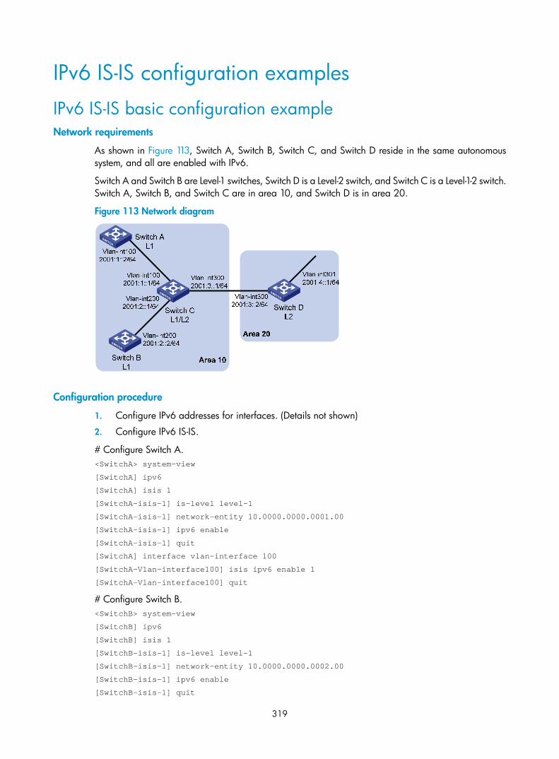
319
IPv6 IS-IS configuration examples
IPv6 IS-IS basic configuration example Network requirements
As shown in Figure 113, Switch A, Switch B, Switch C, and Switch D reside in the same autonomous system, and all are enabled with IPv6.
Switch A and Switch B are Level-1 switches, Switch D is a Level-2 switch, and Switch C is a Level-1-2 switch. Switch A, Switch B, and Switch C are in area 10, and Switch D is in area 20.
Figure 113 Network diagram
Configuration procedure
1. Configure IPv6 addresses for interfaces. (Details not shown)
2. Configure IPv6 IS-IS.
# Configure Switch A. <SwitchA> system-view
[SwitchA] ipv6
[SwitchA] isis 1
[SwitchA-isis-1] is-level level-1
[SwitchA-isis-1] network-entity 10.0000.0000.0001.00
[SwitchA-isis-1] ipv6 enable
[SwitchA-isis-1] quit
[SwitchA] interface vlan-interface 100
[SwitchA-Vlan-interface100] isis ipv6 enable 1
[SwitchA-Vlan-interface100] quit
# Configure Switch B. <SwitchB> system-view
[SwitchB] ipv6
[SwitchB] isis 1
[SwitchB-isis-1] is-level level-1
[SwitchB-isis-1] network-entity 10.0000.0000.0002.00
[SwitchB-isis-1] ipv6 enable
[SwitchB-isis-1] quit

320
[SwitchB] interface vlan-interface 200
[SwitchB-Vlan-interface200] isis ipv6 enable 1
[SwitchB-Vlan-interface200] quit
# Configure Switch C. <SwitchC> system-view
[SwitchC] ipv6
[SwitchC] isis 1
[SwitchC-isis-1] network-entity 10.0000.0000.0003.00
[SwitchC-isis-1] ipv6 enable
[SwitchC-isis-1] quit
[SwitchC] interface vlan-interface 100
[SwitchC-Vlan-interface100] isis ipv6 enable 1
[SwitchC-Vlan-interface100] quit
[SwitchC] interface vlan-interface 200
[SwitchC-Vlan-interface200] isis ipv6 enable 1
[SwitchC-Vlan-interface200] quit
[SwitchC] interface vlan-interface 300
[SwitchC-Vlan-interface300] isis ipv6 enable 1
[SwitchC-Vlan-interface300] quit
# Configure Switch D. <SwitchD> system-view
[SwitchD] ipv6
[SwitchD] isis 1
[SwitchD-isis-1] is-level level-2
[SwitchD-isis-1] network-entity 20.0000.0000.0004.00
[SwitchD-isis-1] ipv6 enable
[SwitchD-isis-1] quit
[SwitchD] interface vlan-interface 300
[SwitchD-Vlan-interface300] isis ipv6 enable 1
[SwitchD-Vlan-interface300] quit
[SwitchD] interface vlan-interface 301
[SwitchD-Vlan-interface301] isis ipv6 enable 1
[SwitchD-Vlan-interface301] quit
3. Verify the configuration.
# Display the IPv6 IS-IS routing table of Switch A. [SwitchA] display isis route ipv6
Route information for ISIS(1)
-----------------------------
ISIS(1) IPv6 Level-1 Forwarding Table
-------------------------------------
Destination: :: PrefixLen: 0
Flag : R/-/- Cost : 10
Next Hop : FE80::200:FF:FE0F:4 Interface: Vlan100
Destination: 2001:1:: PrefixLen: 64

321
Flag : D/L/- Cost : 10
Next Hop : Direct Interface: Vlan100
Destination: 2001:2:: PrefixLen: 64
Flag : R/-/- Cost : 20
Next Hop : FE80::200:FF:FE0F:4 Interface: Vlan100
Destination: 2001:3:: PrefixLen: 64
Flag : R/-/- Cost : 20
Next Hop : FE80::200:FF:FE0F:4 Interface: Vlan100
Flags: D-Direct, R-Added to RM, L-Advertised in LSPs, U-Up/Down Bit Set
# Display the IPv6 IS-IS routing table of Switch B. [SwitchB] display isis route ipv6
Route information for ISIS(1)
-----------------------------
ISIS(1) IPv6 Level-1 Forwarding Table
-------------------------------------
Destination: :: PrefixLen: 0
Flag : R/-/- Cost : 10
Next Hop : FE80::200:FF:FE0F:4 Interface: Vlan200
Destination: 2001:1:: PrefixLen: 64
Flag : D/L/- Cost : 10
Next Hop : FE80::200:FF:FE0F:4 Interface: Vlan200
Destination: 2001:2:: PrefixLen: 64
Flag : R/-/- Cost : 20
Next Hop : Direct Interface: Vlan200
Destination: 2001:3:: PrefixLen: 64
Flag : R/-/- Cost : 20
Next Hop : FE80::200:FF:FE0F:4 Interface: Vlan200
Flags: D-Direct, R-Added to RM, L-Advertised in LSPs, U-Up/Down Bit Set
# Display the IPv6 IS-IS routing table of Switch C. [SwitchC] display isis route ipv6
Route information for ISIS(1)
-----------------------------
ISIS(1) IPv6 Level-1 Forwarding Table
-------------------------------------
Destination: 2001:1:: PrefixLen: 64
Flag : D/L/- Cost : 10
Next Hop : Direct Interface: Vlan100

322
Destination: 2001:2:: PrefixLen: 64
Flag : D/L/- Cost : 10
Next Hop : Direct Interface: Vlan200
Destination: 2001:3:: PrefixLen: 64
Flag : D/L/- Cost : 10
Next Hop : Direct Interface: Vlan300
Flags: D-Direct, R-Added to RM, L-Advertised in LSPs, U-Up/Down Bit Set
ISIS(1) IPv6 Level-2 Forwarding Table
-------------------------------------
Destination: 2001:1:: PrefixLen: 64
Flag : D/L/- Cost : 10
Next Hop : Direct Interface: Vlan100
Destination: 2001:2:: PrefixLen: 64
Flag : D/L/- Cost : 10
Next Hop : Direct Interface: Vlan200
Destination: 2001:3:: PrefixLen: 64
Flag : D/L/- Cost : 10
Next Hop : Direct Interface: Vlan300
Destination: 2001:4::1 PrefixLen: 128
Flag : R/-/- Cost : 10
Next Hop : FE80::20F:E2FF:FE3E:FA3D Interface: Vlan300
Flags: D-Direct, R-Added to RM, L-Advertised in LSPs, U-Up/Down Bit Set
# Display the IPv6 IS-IS routing table of Switch D. [SwitchD] display isis route ipv6
Route information for ISIS(1)
-----------------------------
ISIS(1) IPv6 Level-2 Forwarding Table
-------------------------------------
Destination: 2001:1:: PrefixLen: 64
Flag : R/-/- Cost : 20
Next Hop : FE80::200:FF:FE0F:4 Interface: Vlan300
Destination: 2001:2:: PrefixLen: 64
Flag : R/-/- Cost : 20
Next Hop : FE80::200:FF:FE0F:4 Interface: Vlan300
Destination: 2001:3:: PrefixLen: 64

323
Flag : D/L/- Cost : 10
Next Hop : Direct Interface: Vlan300
Destination: 2001:4::1 PrefixLen: 128
Flag : D/L/- Cost : 0
Next Hop : Direct Interface: Loop1
Flags: D-Direct, R-Added to RM, L-Advertised in LSPs, U-Up/Down Bit Set
Configuring BFD for IPv6 IS-IS Network requirements
As shown in Figure 114, configure IPv6 IS-IS on Switch A, Switch B, and Switch C and configure BFD over the link Switch A<—>L2 Switch<—>Switch B.
After the link between Switch B and the Layer-2 switch fails, BFD can quickly detect the failure and notify IPv6 IS-IS of the failure. Then Switch A and Switch B communicate through Switch C.
Figure 114 Network diagram
Device Interface IPv6 address Device Interface IPv6 address Switch A Vlan-int10 2001::1/64 Switch B Vlan-int10 2001::2/64 Vlan-int11 2001:2::1/64 Vlan-int13 2001:3::2/64 Switch C Vlan-int11 2001:2::2/64 Vlan-int13 2001:3::1/64
Configuration procedure
1. Configure IP addresses for interfaces. (Details not shown)
2. Configure IPv6 IS-IS.
# Configure Switch A. <SwitchA> system-view
[SwitchA] ipv6
[SwitchA] isis 1
[SwitchA-isis-1] is-level level-1
[SwitchA-isis-1] network-entity 10.0000.0000.0001.00
[SwitchA-isis-1] ipv6 enable
[SwitchA-isis-1] quit
[SwitchA] interface vlan-interface 10

324
[SwitchA-Vlan-interface10] isis ipv6 enable 1
[SwitchA-Vlan-interface10] quit
[SwitchA] interface vlan-interface 11
[SwitchA-Vlan-interface11] isis ipv6 enable 1
[SwitchA-Vlan-interface11] quit
# Configure Switch B. <SwitchB> system-view
[SwitchB] ipv6
[SwitchB] isis 1
[SwitchB-isis-1] is-level level-1
[SwitchB-isis-1] network-entity 10.0000.0000.0002.00
[SwitchB-isis-1] ipv6 enable
[SwitchB-isis-1] quit
[SwitchB] interface vlan-interface 10
[SwitchB-Vlan-interface10] isis ipv6 enable 1
[SwitchB-Vlan-interface10] quit
[SwitchB] interface vlan-interface 13
[SwitchB-Vlan-interface13] isis ipv6 enable 1
[SwitchB-Vlan-interface13] quit
# Configure Switch C. <SwitchC> system-view
[SwitchC] ipv6
[SwitchC] isis 1
[SwitchC-isis-1] network-entity 10.0000.0000.0003.00
[SwitchC-isis-1] ipv6 enable
[SwitchC-isis-1] quit
[SwitchC] interface vlan-interface 11
[SwitchC-Vlan-interface11] isis ipv6 enable 1
[SwitchC-Vlan-interface11] quit
[SwitchC] interface vlan-interface 13
[SwitchC-Vlan-interface13] isis ipv6 enable 1
[SwitchC-Vlan-interface13] quit
3. Configure BFD functions.
# Enable BFD on Switch A and configure BFD parameters. [SwitchA] bfd session init-mode active
[SwitchA] interface vlan-interface 10
[SwitchA-Vlan-interface10] isis ipv6 bfd enable
[SwitchA-Vlan-interface10] bfd min-transmit-interval 500
[SwitchA-Vlan-interface10] bfd min-receive-interval 500
[SwitchA-Vlan-interface10] bfd detect-multiplier 7
[SwitchA-Vlan-interface10] return
# Enable BFD on Switch B and configure BFD parameters. [SwitchB] bfd session init-mode active
[SwitchB] interface vlan-interface 10
[SwitchB-Vlan-interface10] isis ipv6 bfd enable
[SwitchB-Vlan-interface10] bfd min-transmit-interval 500
[SwitchB-Vlan-interface10] bfd min-receive-interval 500

325
[SwitchB-Vlan-interface10] bfd detect-multiplier 6
4. Verify configuration.
The following operations are made on Switch A. Operations for Switch B are similar and are not shown here.
# Display the BFD information of Switch A. <SwitchA> display bfd session
Total Session Num: 1 Init Mode: Active
IPv6 Session Working Under Ctrl Mode:
Local Discr: 1441 Remote Discr: 1450
Source IP: FE80::20F:FF:FE00:1202 (link-local address of VLAN-interface 10 on Switch A)
Destination IP: FE80::20F:FF:FE00:1200 (link-local address of VLAN-interface 10 on Switch B)
Session State: Up Interface: Vlan10
Hold Time: /
# Display route 2001:4::0/64 on Switch A, and you can see that Switch A and Switch B communicate through the Layer-2 switch. <SwitchA> display ipv6 routing-table 2001:4::0 64 verbose
Routing Table :
Summary Count : 2
Destination : 2001:4::0 PrefixLength : 64
NextHop : 2001::2 Preference : 15
IpPrecedence : QosLcId :
RelayNextHop : :: Tag : 0H
Neighbor : :: ProcessID : 0
Interface : Vlan-interface10 Protocol : ISISv6
State : Active Adv Cost : 20
Tunnel ID : 0x0 Label : NULL
Age : 4538sec
Destination : 2001:4::0 PrefixLength : 64
NextHop : 2001:2::2 Preference : 15
IpPrecedence : QosLcId :
RelayNextHop : :: Tag : 0H
Neighbor : :: ProcessID : 0
Interface : Vlan-interface11 Protocol : ISISv6
State : Invalid Adv Cost : 30
Tunnel ID : 0x0 Label : NULL
Age : 4515sec
# Enable BFD debugging on Switch A. <SwitchA> debugging bfd scm
<SwitchA> debugging bfd event
<SwitchA> debugging isis event bfd
<SwitchA> terminal debugging

326
# When the link between Switch B and the Layer-2 switch fails, BFD can quickly detect the failure. #Aug 8 14:54:05:362 2009 SwitchA IFNET/4/INTERFACE UPDOWN:
Trap 1.3.6.1.6.3.1.1.5.3<linkDown>: Interface 983041 is Down, ifAdminStatus is
1, ifOperStatus is 2
#Aug 8 14:54:05:363 2009 SwitchA ISIS/4/ADJ_CHANGE:TrapID(1.3.6.1.2.1.138.0.17<
isisAdjacencyChange>), ISIS Level-2 Adjencency IN Circuit-983041 State Change.
#Aug 8 14:54:05:364 2009 SwitchA ISIS/4/ADJ_CHANGE:TrapID(1.3.6.1.2.1.138.0.17<
isisAdjacencyChange>), ISIS Level-1 Adjencency IN Circuit-983041 State Change.
%Aug 8 14:54:05:365 2009 SwitchA IFNET/4/LINK UPDOWN: vlan10: link status is DOWN
%Aug 8 14:54:05:366 2009 SwitchA IFNET/4/UPDOWN: Line protocol on the interface Vlan10 is DOWN
%Aug 8 14:54:05:367 2009 SwitchA ISIS/4/ADJLOG:ISIS-1-ADJCHANGE: Adjacency To 0000.0000.0002 (vlan10) DOWN, Level-2 Circuit Down.
%Aug 8 14:54:05:367 2009 SwitchA ISIS/4/ADJLOG:ISIS-1-ADJCHANGE: Adjacency To 0000.0000.0002 (vlan10) DOWN, Level-2 Adjacency clear.
%Aug 8 14:54:05:368 2009 SwitchA ISIS/4/ADJLOG:ISIS-1-ADJCHANGE: Adjacency To 0000.0000.0002 (vlan10) DOWN, Level-1 Circuit Down.
%Aug 8 14:54:05:369 2009 SwitchA ISIS/4/ADJLOG:ISIS-1-ADJCHANGE: Adjacency To 0000.0000.0002 (vlan10) DOWN, Level-1 Adjacency clear.
*Aug 8 14:54:05:369 2009 SwitchA ISIS/6/ISIS: ISIS-1-BFD: Recieve BFD session down . Type 0. DstIPAddr: FE80::20F:FF:FE00:1200 , SrcIPAddr: FE80::20F:FF:FE00:1202
*Aug 8 14:54:05:370 2009 SwitchA ISIS/6/ISIS: ISIS-1-BFD: Success to send msg. Msg type 1 delete session. IfPhyIndex: 5 , DstIPAddr: FE80::20F:FF:FE00:1200 , SrcIPAddr: FE80::20F:FF:FE00:1202. NeighborType:Level-1.
# Display the BFD information of Switch A. You can see that Switch A has removed its neighbor relationship with Switch B and therefore no information is output. <SwitchA> display bfd session
# Display route 2001:4::0/64 on Switch A, and you can see that Switch A and Switch B communicate through Switch C. <SwitchA> display ipv6 routing-table 2001:4::0 64 verbose
Routing Table :
Summary Count : 1
Destination : 2001:4::0 PrefixLength : 64
NextHop : 2001:2::2 Preference : 15
IpPrecedence : QosLcId :
RelayNextHop : :: Tag : 0H
Neighbor : :: ProcessID : 0
Interface : Vlan-interface11 Protocol : ISISv6
State : Invalid Adv Cost : 30
Tunnel ID : 0x0 Label : NULL
Age : 4610sec

327
IPv6 BGP configuration
NOTE:
• The term router in this document refers to both routers and Layer 3 switches.
• This chapter describes only configuration for IPv6 BGP. For BGP related information, see the chapter “BGP configuration.”
• The 3600 v2 SI Switch Series does not support IPv6 BGP.
IPv6 BGP overview BGP-4 was designed to carry only IPv4 routing information, so other network layer protocols such as IPv6 are not supported.
To support multiple network layer protocols, IETF extended BGP-4 by introducing Multiprotocol BGP (MP-BGP), which is defined in RFC 2858 (multiprotocol extensions for BGP-4).
For brevity purposes, MP-BGP for IPv6 is called “IPv6 BGP.”
IPv6 BGP puts IPv6 network layer information into the attributes of Network Layer Reachability Information (NLRI) and NEXT_HOP.
The NLRI attribute of IPv6 BGP involves the following:
• MP_REACH_NLRI: Multiprotocol Reachable NLRI, for advertising reachable route and next hop information.
• MP_UNREACH_NLRI: Multiprotocol Unreachable NLRI, for withdrawal of unreachable routes.
The NEXT_HOP attribute of IPv6 BGP is identified by an IPv6 unicast address or IPv6 local link address.
IPv6 BGP has the same messaging and routing mechanisms as BGP.

328
IPv6 BGP configuration task list Complete the following tasks to configure IPv6 BGP:
Task Remarks
Configuring IPv6 BGP basic functions
Specifying an IPv6 BGP peer Required
Injecting a local IPv6 route Optional
Configuring a preferred value for routes from a peer or peer group Optional
Specifying the source interface for establishing TCP connections Optional
Allowing the establishment of an indirect eBGP connection
Optional
Configuring a description for an IPv6 peer or peer group
Optional
Disabling session establishment to an IPv6 peer or peer group Optional
Logging IPv6 peer or peer group state changes Optional
Controlling route distribution and reception
Configuring IPv6 BGP route redistribution Optional
Configuring IPv6 BGP route summarization Optional
Advertising a default route to an IPv6 peer or peer group Optional
Configuring outbound route filtering Optional
Configuring inbound route filtering Optional
Configuring IPv6 BGP and IGP route synchronization Optional
Configuring route dampening Optional
Configuring IPv6 BGP route attributes
Configuring IPv6 BGP preference and default LOCAL_PREF and NEXT_HOP attributes Optional
Configuring the MED attribute Optional
Configuring the AS_PATH attribute Optional
Tuning and optimizing IPv6 BGP networks
Configuring IPv6 BGP timers Optional
Configuring IPv6 BGP soft reset Optional
Enabling the IPv6 BGP ORF capability Optional
Enabling 4-byte AS number suppression Optional
Configuring the maximum number of load-balanced routes Optional
Enabling MD5 authentication for TCP connections Optional
Applying an IPsec policy to an IPv6 BGP peer or peer group Optional
Configuring a large-scale IPv6 BGP network
Configuring IPv6 BGP peer group Optional
Configuring IPv6 BGP community Optional

329
Task Remarks Configuring an IPv6 BGP route reflector Optional
Configuring BFD for IPv6 BGP Optional
Configuring IPv6 BGP basic functions
Configuration prerequisites Before configuring IPv6 BGP basic functions, complete the following tasks:
• Specify IP addresses for interfaces
• Enable IPv6
NOTE:
Create a peer group before configuring basic functions for it. For related information, see “Configuring IPv6 BGP peer group.”
Specifying an IPv6 BGP peer Follow these steps to configure an IPv6 BGP peer:
To do… Use the command… Remarks Enter system view system-view —
Enter BGP view bgp as-number —
Specify a router ID router-id router-id Optional
Required if no IP addresses are configured for any interfaces.
Enter IPv6 address family view ipv6-family —
Specify an IPv6 peer peer ipv6-address as-number as-number
Required
Injecting a local IPv6 route Follow these steps to configure advertise a local route into the routing table:
To do… Use the command… Remarks Enter system view system-view —
Enter BGP view bgp as-number —
Enter IPv6 address family view ipv6-family —
Inject a local route into the IPv6 BGP routing table
network ipv6-address prefix-length [ short-cut | route-policy route-policy-name ]
Required
Not added by default

330
Configuring a preferred value for routes from a peer or peer group
Follow these steps to configure a preferred value for routes received from a peer or peer group:
To do… Use the command… Remarks Enter system view system-view —
Enter BGP view bgp as-number —
Enter IPv6 address family view ipv6-family —
Configure a preferred value for routes received from an IPv6 peer or peer group
peer { ipv6-group-name | ipv6-address } preferred-value value
Required
By default, the preferred value is 0.
NOTE:
If you both reference a routing policy and use the command peer { ipv6-group-name | ipv6-address } preferred-value value to set a preferred value for routes from a peer, the routing policy sets the specific preferred value for routes matching it. If the preferred value in the routing policy is zero, the routes use thevalue set with the peer { ipv6-group-name | ipv6-address } preferred-value value command. For how touse a routing policy to set a preferred value, see the command peer { group-name | ipv4-address | ipv6-address } route-policy route-policy-name { import | export } in this document, and the command apply preferred-value preferred-value in the chapter “Routing policy configuration commands.”
Specifying the source interface for establishing TCP connections
IPv6 BGP uses TCP as the transport layer protocol. By default, IPv6 BGP uses the output interface of the optimal route to a peer or peer group as the source interface for establishing TCP connections to the peer or peer group.
If an IPv6 BGP router has multiple links to a peer, and the source interface fails, IPv6 BGP has to reestablish TCP connections, causing network oscillation. To enhance stability of IPv6 BGP connections, HP recommends using a loopback interface as the source interface.
Follow these steps to specify the source interface for establishing TCP connections to a BGP peer or peer group:
To do… Use the command… Remarks Enter system view system-view —
Enter BGP view bgp as-number —
Enter IPv6 address family view ipv6-family —
Specify the source interface for establishing TCP connections to an IPv6 BGP peer or peer group
peer { ipv6-group-name | ipv6-address } connect-interface interface-type interface-number
Required
By default, IPv6 BGP uses the outbound interface of the best route to the IPv6 BGP peer or peer group as the source interface for establishing a TCP connection.

331
NOTE:
To establish a BGP connection, specify on the local router the source interface for establishing the TCP connection to the peer on the peering BGP router. Otherwise, the local BGP router may fail to establish TCP connection to the peer when using the outbound interface of the best route as the source interface.
Allowing the establishment of an indirect eBGP connection Follow these steps to allow the establishment of eBGP connection to an indirectly connected peer or peer group:
To do… Use the command… Remarks Enter system view system-view —
Enter BGP view bgp as-number —
Enter IPv6 address family view ipv6-family —
Allow the establishment of eBGP connection to an indirectly connected peer or peer group
peer { ipv6-group-name | ipv6-address } ebgp-max-hop [ hop-count ]
Required
Not configured by default.
NOTE:
Direct links must be available between eBGP peers. If not, you can use the peer ebgp-max-hop commandto establish a multi-hop TCP connection in between. However, do not use this command for direct eBGP connections with loopback interfaces.
Configuring a description for an IPv6 peer or peer group Follow these steps to configure description for an IPv6 peer or peer group:
To do… Use the command… Remarks
Enter system view system-view —
Enter BGP view bgp as-number —
Enter IPv6 address family view ipv6-family —
Configure a description for an IPv6 peer or peer group
peer { ipv6-group-name | ipv6-address } description description-text
Optional
Not configured by default.
NOTE:
The peer group to be configured with a description must have been created.
Disabling session establishment to an IPv6 peer or peer group Follow these steps to disable session establishment to a peer or peer group:
To do… Use the command… Remarks
Enter system view system-view —
Enter BGP view bgp as-number —

332
To do… Use the command… Remarks
Enter IPv6 address family view ipv6-family —
Disable session establishment to an IPv6 peer or peer group
peer { ipv6-group-name | ipv6-address } ignore
Optional
Not disabled by default
Logging IPv6 peer or peer group state changes Follow these steps to configure to log on the session and event information of an IPv6 peer or peer group:
To do… Use the command… Remarks
Enter system view system-view —
Enter BGP view bgp as-number —
Enable logging of peer changes globally
log-peer-change Optional
Enabled by default.
Enter IPv6 address family view ipv6-family —
Enable the state change logging for an IPv6 peer or peer group
peer { ipv6-group-name | ipv6-address } log-change
Optional
Enabled by default.
NOTE:
See Layer 3—IP Routing Command Reference for information about the log-peer-change command.
Controlling route distribution and reception This task includes routing information filtering, routing policy application, and route dampening.
Configuration prerequisites • Enable IPv6
• Configure IPv6 BGP basic functions
Configuring IPv6 BGP route redistribution Follow these steps to configure IPv6 BGP route redistribution:
To do… Use the command… Remarks Enter system view system-view —
Enter BGP view bgp as-number —
Enter IPv6 address family view ipv6-family —
Enable default route redistribution into the IPv6 BGP routing table
default-route imported Optional
Not enabled by default.
Enable route redistribution from another routing protocol
import-route protocol [ process-id [ med med-value | route-policy route-policy-name ] * ]
Required
Not enabled by default.

333
NOTE:
If the default-route imported command is not configured, using the import-route command cannot redistribute any IGP default route.
Configuring IPv6 BGP route summarization To reduce the routing table size on medium and large BGP networks, configure route summarization on BGP routers. BGP supports only manual summarization of IPv6 routes.
Follow these steps to configure IPv6 BGP route summarization:
To do… Use the command… Remarks Enter system view system-view —
Enter BGP view bgp as-number —
Enter IPv6 address family view
ipv6-family —
Configure manual route summarization
aggregate ipv6-address prefix-length [ as-set | attribute-policy route-policy-name | detail-suppressed | origin-policy route-policy-name | suppress-policy route-policy-name ] *
Required
Not configured by default.
Advertising a default route to an IPv6 peer or peer group Follow these steps to advertise a default route to an IPv6 peer or peer group:
To do… Use the command… Remarks Enter system view system-view —
Enter BGP view bgp as-number —
Enter IPv6 address family view ipv6-family —
Advertise a default route to an IPv6 peer or peer group
peer { ipv6-group-name | ipv6-address } default-route-advertise [ route-policy route-policy-name ]
Required
Not advertised by default.
NOTE:
With the peer default-route-advertise command executed, the local router advertises a default route withitself as the next hop to the specified IPv6 peer or peer group, regardless of whether the default route is available in the routing table.
Configuring outbound route filtering Follow these steps to configure outbound route filtering:
To do… Use the command… Remarks Enter system view system-view —
Enter BGP view bgp as-number —
Enter IPv6 address family view ipv6-family —

334
To do… Use the command… Remarks
Configure the filtering of outgoing routes
filter-policy { acl6-number | ipv6-prefix ipv6-prefix-name } export [ protocol process-id ]
Required
Not configured by default.
Apply a routing policy to routes advertised to an IPv6 peer or peer group
peer { ipv6-group-name | ipv6-address } route-policy route-policy-name export
Required
Not applied by default.
Specify an IPv6 ACL to filter routes advertised to an IPv6 peer or peer group
peer { ipv6-group-name | ipv6-address } filter-policy acl6-number export
Required
Not specified by default.
Specify an AS path ACL to filter routes advertised to an IPv6 peer or peer group
peer { ipv6-group-name | ipv6-address } as-path-acl as-path-acl-number export
Required
Not specified by default.
Specify an IPv6 prefix list to filter routes advertised to an IPv6 peer or peer group
peer { ipv6-group-name | ipv6-address } ipv6-prefix ipv6-prefix-name export
Required
Not specified by default.
NOTE:
IPv6 BGP advertises routes passing the specified policy to peers. Using the protocol argument can filter only the routes redistributed from the specified protocol. If no protocol is specified, IPv6 BGP filters all routes to be advertised, including redistributed routes and routes imported with the network command.
Configuring inbound route filtering Follow these steps to configure inbound route filtering:
To do… Use the command… Remarks Enter system view system-view —
Enter BGP view bgp as-number —
Enter IPv6 address family view ipv6-family —
Configure inbound route filtering filter-policy { acl6-number | ipv6-prefix ipv6-prefix-name } import
Required
Not configured by default.
Apply a routing policy to routes from an IPv6 peer or peer group
peer { ipv6-group-name | ipv6-address } route-policy route-policy-name import
Required
Not applied by default.
Specify an ACL to filter routes imported from an IPv6 peer or peer group
peer { ipv6-group-name | ipv6-address } filter-policy acl6-number import
Required
Not specified by default.
Specify an AS path ACL to filter routing information imported from an IPv6 peer or peer group
peer { ipv6-group-name | ipv6-address } as-path-acl as-path-acl-number import
Required
Not specified by default.
Specify an IPv6 prefix list to filter routing information imported from an IPv6 peer or peer group
peer { ipv6-group-name | ipv6-address } ipv6-prefix ipv6-prefix-name import
Required
Not specified by default.

335
To do… Use the command… Remarks Specify the upper limit of prefixes allowed to receive from an IPv6 peer or peer group
peer { ipv6-group-name | ipv6-address } route-limit limit [ percentage ]
Optional
Unlimited by default.
NOTE:
• Only routes passing the configured filtering can be added into the local IPv6 BGP routing table.
• Members of a peer group can have different inbound route filtering policies.
Configuring IPv6 BGP and IGP route synchronization By default, upon receiving an iBGP route, an IPv6 BGP router checks the route’s next hop. If the next hop is reachable, the IPv6 BGP router advertises the route to eBGP peers. If the synchronization feature is configured, in addition to the reachability check of the next hop, the IPv6 BGP router must find an active IGP route with the same destination network segment before it can advertise the iBGP route (use the display ipv6 routing-table protocol command to check the IGP route state).
Follow these steps to configure IPv6 BGP and IGP route synchronization:
To do… Use the command… Remarks
Enter system view system-view —
Enter BGP view bgp as-number —
Enter IPv6 address family view ipv6-family —
Enable route synchronization between IPv6 BGP and IGP synchronization
Required
Not enabled by default.
Configuring route dampening Follow these steps to configure BGP route dampening:
To do… Use the command… Remarks Enter system view system-view —
Enter BGP view bgp as-number —
Enter IPv6 address family view ipv6-family —
Configure IPv6 BGP route dampening parameters
dampening [ half-life-reachable half-life-unreachable reuse suppress ceiling | route-policy route-policy-name ]*
Optional
Not configured by default.
Configuring IPv6 BGP route attributes Use the following IPv6 BGP route attributes to modify BGP routing policy:
• IPv6 BGP protocol preference
• Default LOCAL_PREF attribute
• MED attribute

336
• NEXT_HOP attribute
• AS_PATH attribute
Configuration prerequisites Before configuring IPv6 BGP route attributes, complete the following tasks:
• Enabled IPv6 function
• Configured IPv6 BGP basic functions
Configuring IPv6 BGP preference and default LOCAL_PREF and NEXT_HOP attributes
Follow these steps to perform this configuration:
To do… Use the command… Remarks Enter system view system-view —
Enter BGP view bgp as-number —
Enter IPv6 address family view ipv6-family —
Configure preference values for IPv6 BGP external, internal, and local routes
preference { external-preference internal-preference local-preference | route-policy route-policy-name }
Optional
The default preference values of external, internal, and local routes are 255, 255, and 130, respectively.
Configure the default local preference default local-preference value
Optional
The value defaults to 100.
Advertise routes to an IPv6 peer or peer group with the local router as the next hop
peer { ipv6-group-name | ipv6-address } next-hop-local
Required
By default, IPv6 BGP specifies the local router as the next hop for routes sent to an IPv6 eBGP peer or peer group, but does not change the next hop for routes sent to an IPv6 iBGP peer or peer group.
NOTE:
• To ensure an iBGP peer can find the correct next hop, configure routes advertised to the IPv6 iBGP peeror peer group to use the local router as the next hop. If BGP load balancing is configured, the local router specifies itself as the next hop of routes sent to an IPv6 iBGP peer or peer group regardless of whether the peer next-hop-local command is configured.
• In a third party next hop network where the two IPv6 eBGP peers reside in a common broadcast subnet,the router does not change the next hop for routes sent to the IPv6 eBGP peer or peer group by default,unless the peer next-hop-local command is configured.
Configuring the MED attribute Follow these steps to configure the MED attribute:

337
To do… Use the command… Remarks Enter system view system-view —
Enter BGP view bgp as-number —
Enter IPv6 address family view ipv6-family —
Configure a default MED value default med med-value Optional
Defaults to 0
Enable the comparison of MED for routes from different eBGP peers compare-different-as-med
Optional
Not enabled by default.
Enable the comparison of MED for routes from each AS
bestroute compare-med Optional
Disabled by default
Enable the comparison of MED for routes from confederation peers bestroute med-confederation
Optional
Disabled by default
Configuring the AS_PATH attribute Follow these steps to configure the AS_PATH attribute:
To do… Use the command… Remarks Enter system view system-view —
Enter BGP view bgp as-number —
Enter IPv6 address family view ipv6-family —
Allow the local AS number to appear in AS_PATH of routes from a peer or peer group and specify the repeat times
peer { ipv6-group-name | ipv6-address } allow-as-loop [ number ]
Optional
Not allowed by default
Specify a fake AS number for an IPv6 peer or peer group
peer { ipv6-group-name | ipv6-address } fake-as as-number
Optional
Not specified by default.
Disable IPv6 BGP from considering the AS_PATH during best route selection
bestroute as-path-neglect Optional
Enabled by default.
Configure to carry only the public AS number in updates sent to a peer or peer group
peer { ipv6-group-name | ipv6-address } public-as-only
Optional
By default, IPv6 BGP updates carry a private AS number.
Substitute the local AS number for the AS number of an IPv6 peer or peer group identified in the AS_PATH attribute
peer { ipv6-group-name | ipv6-address } substitute-as
Optional
Not substituted by default
Tuning and optimizing IPv6 BGP networks This section describes configurations of IPv6 BGP timers, IPv6 BGP connection soft reset, and the maximum number of load balanced routes.
• IPv6 BGP timers

338
After establishing an IPv6 BGP connection, two routers send keepalive messages periodically to each other to maintain the connection. If a router receives no keepalive message from the peer after the holdtime elapses, it tears down the connection.
When establishing an IPv6 BGP connection, the two parties compare their holdtimes, taking the shorter one as the common holdtime. If the holdtime is 0, neither keepalive massage is sent, nor holdtime is checked.
• IPv6 BGP connection soft reset
After modifying a route selection policy, you must reset IPv6 BGP connections to make the new one take effect. The current IPv6 BGP implementation supports the route-refresh feature that enables dynamic route refresh without needing to disconnect IPv6 BGP links.
After this feature is enabled on all IPv6 BGP routers, a router that wants to apply a new route selection policy advertises a route-refresh message to its peers, which then send their routing information to the router. After receiving the routing information, the router can perform dynamic route update by using the new policy without tearing down connections.
If a peer not supporting route-refresh exists in the network, you must configure the peer keep-all-routes command to save all routes from the peer. When the routing policy is changed, the system will update the IPv6 BGP routing table and apply the new policy.
Configuration prerequisites Before configuring IPv6 BGP timers, complete the following tasks:
• Enable IPv6
• Configure IPv6 BGP basic functions
Configuring IPv6 BGP timers Follow these steps to configure IPv6 BGP timers:
To do… Use the command… Remarks Enter system view system-view —
Enter BGP view bgp as-number —
Enter IPv6 address family view ipv6-family —
Configure IPv6 BGP timers
Specify keepalive interval and holdtime
timer keepalive keepalive hold holdtime Optional
The keepalive interval defaults to 60 seconds, holdtime defaults to 180 seconds.
Configure keepalive interval and holdtime for an IPv6 peer or peer group
peer { ipv6-group-name | ipv6-address } timer keepalive keepalive hold holdtime
Configure the interval for sending the same update to an IPv6 peer or peer group
peer { ipv6-group-name | ipv6-address } route-update-interval interval
Optional
The interval for sending the same update to an iBGP peer or an eBGP peer defaults to 15 seconds or 30 seconds.

339
NOTE:
• Timers configured using the timer command have lower priority than timers configured using the peertimer command.
• The holdtime interval must be at least three times the keepalive interval.
Configuring IPv6 BGP soft reset Enable route refresh
Follow these steps to enable route refresh:
To do… Use the command… Remarks Enter system view system-view —
Enter BGP view bgp as-number —
Enter IPv6 address family view ipv6-family —
Enable route refresh peer { ipv6-group-name | ipv6-address } capability-advertise route-refresh
Optional
Enabled by default.
Perform manual soft-reset
Follow these steps to perform manual soft reset:
To do… Use the command… Remarks Enter system view system-view —
Enter BGP view bgp as-number —
Enter IPv6 address family view ipv6-family —
Save all routes from an IPv6 peer or peer group, not letting them go through the inbound policy
peer { ipv6-group-name | ipv6-address } keep-all-routes
Optional
Not saved by default.
Return to user view return
Required Soft-reset BGP connections manually
refresh bgp ipv6 { all | ipv6-address | group ipv6-group-name | external | internal } { export | import }
NOTE:
If the peer keep-all-routes command is used, all routes from the peer or peer group are saved regardlessof whether the filtering policy is available. These routes will be used to generate IPv6 BGP routes after soft-reset is performed.
Enabling the IPv6 BGP ORF capability The BGP Outbound Route Filter (ORF) feature allows a BGP speaker to send its BGP peer a set of ORFs through route-refresh messages. The peer then applies the ORFs, in addition to its local routing policies (if any), to filter updates to the BGP speaker, reducing the number of exchanged update messages and saving network resources.
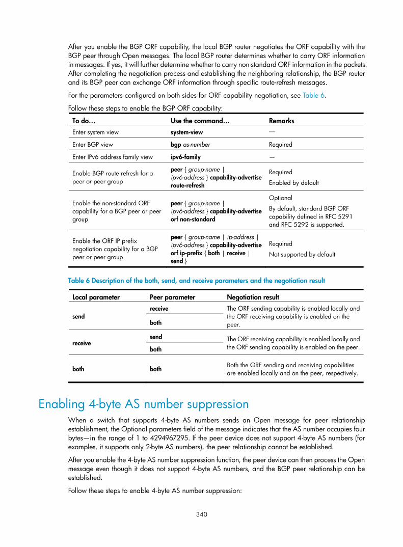
340
After you enable the BGP ORF capability, the local BGP router negotiates the ORF capability with the BGP peer through Open messages. The local BGP router determines whether to carry ORF information in messages. If yes, it will further determine whether to carry non-standard ORF information in the packets. After completing the negotiation process and establishing the neighboring relationship, the BGP router and its BGP peer can exchange ORF information through specific route-refresh messages.
For the parameters configured on both sides for ORF capability negotiation, see Table 6.
Follow these steps to enable the BGP ORF capability:
To do… Use the command… Remarks Enter system view system-view —
Enter BGP view bgp as-number Required
Enter IPv6 address family view ipv6-family —
Enable BGP route refresh for a peer or peer group
peer { group-name | ipv6-address } capability-advertise route-refresh
Required
Enabled by default
Enable the non-standard ORF capability for a BGP peer or peer group
peer { group-name | ipv6-address } capability-advertise orf non-standard
Optional
By default, standard BGP ORF capability defined in RFC 5291 and RFC 5292 is supported.
Enable the ORF IP prefix negotiation capability for a BGP peer or peer group
peer { group-name | ip-address | ipv6-address } capability-advertise orf ip-prefix { both | receive | send }
Required
Not supported by default
Table 6 Description of the both, send, and receive parameters and the negotiation result
Local parameter Peer parameter Negotiation result
send receive The ORF sending capability is enabled locally and
the ORF receiving capability is enabled on the peer. both
receive send The ORF receiving capability is enabled locally and
the ORF sending capability is enabled on the peer. both
both both Both the ORF sending and receiving capabilities are enabled locally and on the peer, respectively.
Enabling 4-byte AS number suppression When a switch that supports 4-byte AS numbers sends an Open message for peer relationship establishment, the Optional parameters field of the message indicates that the AS number occupies four bytes—in the range of 1 to 4294967295. If the peer device does not support 4-byte AS numbers (for examples, it supports only 2-byte AS numbers), the peer relationship cannot be established.
After you enable the 4-byte AS number suppression function, the peer device can then process the Open message even though it does not support 4-byte AS numbers, and the BGP peer relationship can be established.
Follow these steps to enable 4-byte AS number suppression:

341
To do… Use the command… Remarks
Enter system view system-view —
Enter BGP view bgp as-number —
Enter IPv6 address family view ipv6-family —
Enable 4-byte AS number suppression
peer { group-name | ip-address } capability-advertise suppress-4-byte-as
Required
Disabled by default.
NOTE:
If the peer device supports 4-byte AS numbers, do not enable the 4-byte AS number suppression function;otherwise, the BGP peer relationship cannot be established.
Configuring the maximum number of load-balanced routes Follow these steps to configure the maximum number of load balanced routes:
To do… Use the command… Remarks Enter system view system-view —
Enter BGP view bgp as-number —
Enter IPv6 address family view ipv6-family —
Configure the maximum number of load balanced routes balance number
Required
By default, no load balancing is enabled.
Enabling MD5 authentication for TCP connections IPv6 BGP employs TCP as the transport protocol. To enhance security, configure IPv6 BGP to perform MD5 authentication when establishing a TCP connection. If the authentication fails, no TCP connection can be established.
Follow these steps to enable MD5 authentication for TCP connections:
To do… Use the command… Remarks Enter system view system-view —
Enter BGP view bgp as-number —
Enter IPv6 address family view ipv6-family —
Enable MD5 authentication when establishing a TCP connection to the peer or peer group
peer { ipv6-group-name | ipv6-address } password { cipher | simple } password
Required
Not enabled by default
NOTE:
• The MD5 authentication for establishing TCP connections does not apply to BGP packets.
• The MD5 authentication requires that the two parties have the same authentication mode and passwordto establish a TCP connection; otherwise, no TCP connection can be established due to authentication failure.

342
Applying an IPsec policy to an IPv6 BGP peer or peer group To protect routing information and defend attacks, IPv6 BGP can authenticate protocol packets by using an IPsec policy.
Outbound IPv6 BGP packets carry the Security Parameter Index (SPI) defined in the IPsec policy. A device uses the SPI carried in a received packet to match against the configured IPsec policy. If they match, the device accepts the packet; otherwise, it discards the packet and will not establish a neighbor relationship with the sending device.
Configuration prerequisites
Before applying an IPsec policy to a peer or peer group, complete following tasks:
• Create an IPsec proposal
• Create an IPsec policy
For more information about IPsec policy configuration, see Security Configuration Guide.
Configuration procedure
Follow these steps to apply an IPsec policy to a peer or peer group
To do… Use the command… Remarks Enter system view system-view —
Enter BGP view bgp as-number —
Enter IPv6 address family view
ipv6-family —
Apply an IPsec policy to a peer or peer group
peer { group-name | ip-address } ipsec-policy policy-name
Required
Not configured by default
NOTE:
An IPsec policy used for IPv6 BGP can be only in manual mode. For more information, see Security Configuration Guide.
Configuring a large-scale IPv6 BGP network In a large-scale IPv6 BGP network, configuration and maintenance become inconvenient because of too many peers. Configuring peer groups makes management easier and improves route distribution efficiency. Peer group includes iBGP peer group, where peers belong to the same AS, and eBGP peer group, where peers belong to different ASs. If peers in an eBGP group belong to the same external AS, the eBGP peer group is a pure eBGP peer group, and if not, a mixed eBGP peer group.
In a peer group, all members have a common policy. Using the community attribute can make a set of IPv6 BGP routers in multiple ASs have the same policy because community sending between IPv6 BGP peers is not limited by AS.
To assure connectivity between iBGP peers, make them fully meshed, but it becomes impractical when too many iBGP peers exist. Using route reflectors or confederation can solve this issue. In a large-scale AS, both of them can be used.
Confederation configuration of IPv6 BGP is identical to that of BGP4, so it is not mentioned here.

343
Configuration prerequisites • Make peer nodes accessible to each other at the network layer
• Enable BGP and configure a router ID.
Configuring IPv6 BGP peer group Configuring an iBGP peer group
Follow these steps to configure an iBGP group:
To do… Use the command… Remarks Enter system view system-view —
Enter BGP view bgp as-number —
Enter IPv6 address family view ipv6-family —
Create an iBGP peer group group ipv6-group-name [ internal ] Required
Add a peer into the group peer ipv6-address group ipv6-group-name [ as-number as-number ]
Required
Not added by default
Creating a pure eBGP peer group
Follow these steps to configure a pure eBGP group:
To do… Use the command… Remarks Enter system view system-view —
Enter BGP view bgp as-number —
Enter IPv6 address family view ipv6-family —
Create an eBGP peer group group ipv6-group-name external Required
Configure the AS number for the peer group
peer ipv6-group-name as-number as-number
Required
Not configured by default.
Add an IPv6 peer into the peer group
peer ipv6-address group ipv6-group-name
Required
Not added by default
NOTE:
• To create a pure eBGP peer group, specify an AS number for the peer group.
• If a peer was added into an eBGP peer group, you cannot specify any AS number for the peer group.
Creating a mixed eBGP peer group
Follow these steps to create a mixed eBGP peer group:
To do… Use the command… Remarks Enter system view system-view —
Enter BGP view bgp as-number —
Enter IPv6 address family view ipv6-family —
Create an eBGP peer group group ipv6-group-name external Required

344
To do… Use the command… Remarks
Specify the AS number of an IPv6 peer
peer ipv6-address as-number as-number
Required
Not specified by default.
Add the IPv6 peer into the peer group
peer ipv6-address group ipv6-group-name
Required
Not added by default
NOTE:
When creating a mixed eBGP peer group, you must create a peer and specify its AS number that is different from AS numbers of other peers; however, you cannot specify AS number for the eBGP peer group.
Configuring IPv6 BGP community Advertise community attribute to an IPv6 peer or peer group
Follow these steps to advertise community attribute to an IPv6 peer or peer group:
To do… Use the command… Remarks Enter system view system-view —
Enter BGP view bgp as-number —
Enter IPv6 address family view ipv6-family —
Advertise community attribute to an IPv6 peer or peer group
peer { ipv6-group-name | ipv6-address } advertise-community
Required
Not advertised by default.
Advertise extended community attribute to an IPv6 peer or peer group
peer { ipv6-group-name | ipv6-address } advertise-ext-community
Required
Not advertised by default.
Apply a routing policy to routes advertised to a peer or peer group
Follow these steps to apply a routing policy to routes advertised to a peer or peer group:
To do… Use the command… Remarks Enter system view system-view —
Enter BGP view bgp as-number —
Enter IPv6 address family view ipv6-family —
Apply a routing policy to routes advertised to an IPv6 peer or peer group
peer { ipv6-group-name | ipv6-address } route-policy route-policy-name export
Required
Not applied by default.
NOTE:
• When configuring IPv6 BGP community, you must configure a routing policy to define the community attribute, and apply the routing policy to route advertisement.
• For routing policy configuration, see the chapter “Routing policy configuration.”

345
Configuring an IPv6 BGP route reflector Follow these steps to configure an IPv6 BGP route reflector:
To do… Use the command… Remarks Enter system view system-view —
Enter BGP view bgp as-number —
Enter IPv6 address family view ipv6-family —
Configure the router as a route reflector and specify an IPv6 peer or peer group as a client
peer { ipv6-group-name | ipv6-address } reflect-client
Required
Not configured by default.
Enable route reflection between clients reflect between-clients
Optional
Enabled by default.
Configure the cluster ID of the route reflector
reflector cluster-id cluster-id Optional
By default, a route reflector uses its router ID as the cluster ID.
NOTE:
• Because the route reflector forwards routing information between clients, you must make clients of a route reflector fully meshed. If clients are fully meshed, HP recommends disabling route reflection between clients to reduce routing costs.
• If a cluster has multiple route reflectors, you must specify the same cluster ID for these route reflectors toavoid routing loops.
Configuring BFD for IPv6 BGP IPv6 BGP maintains neighbor relationships based on the keepalive timer and holdtime timer, which are set in seconds. IPv6 BGP defines that the holdtime interval must be at least three times the keepalive interval. This mechanism makes the detection of a link failure rather slow and thus causes a large quantity of packets to be dropped especially when the failed link is a high-speed link. You can enable BFD to detect the link to a peer. BFD can quickly detect any link failure and thus reduce network convergence time.
Follow these steps to enable BFD for a BGP peer:
To do… Use the command… Remarks Enter system view system-view —
Enable BGP and enter BGP view bgp as-number Required
Not enabled by default
Enter IPv6 address family view ipv6-family —
Enable BFD for the specified BGP peer peer ipv6-address bfd
Required
Not enabled for any BGP peer by default

346
NOTE:
• Before configuring BFD for IPv6 BGP, you need to enable BGP.
• After a link failure occurs, BFD may detect the failure before the system performs GR and as a result, GRwill fail. Therefore, if GR capability is enabled for IPv6 BGP, use BFD with caution.
• For more information about BFD, see High Availability Configuration Guide.
Displaying and maintaining IPv6 BGP
Displaying BGP To do… Use the command… Remarks Display IPv6 BGP peer group information
display bgp ipv6 group [ ipv6-group-name ] [ | { begin | exclude | include } regular-expression ]
Available in any view
Display IPv6 BGP advertised routing information
display bgp ipv6 network [ | { begin | exclude | include } regular-expression ]
Display IPv6 BGP AS path information
display bgp ipv6 paths [ as-regular-expression | | { begin | exclude | include } regular-expression ]
Display IPv6 BGP peer or peer group information
display bgp ipv6 peer [ group-name log-info | ipv4-address verbose | ipv6-address { log-info | verbose } | verbose ] [ | { begin | exclude | include } regular-expression ]
Display the prefix entries in the ORF information of the specified BGP peer
display bgp ipv6 peer { ip-address | ipv6-address } received ipv6-prefix [ | { begin | exclude | include } regular-expression ]
Display IPv6 BGP routing table information
display bgp ipv6 routing-table [ ipv6-address prefix-length ] [ | { begin | exclude | include } regular-expression ]
Display IPv6 BGP routing information matching an AS path ACL
display bgp ipv6 routing-table as-path-acl as-path-acl-number [ | { begin | exclude | include } regular-expression ]
Display IPv6 BGP routing information with the specified community attribute
display bgp ipv6 routing-table community [ aa:nn<1-13> ] [ no-advertise | no-export | no-export-subconfed ]* [ whole-match ] [ | { begin | exclude | include } regular-expression ]
Display IPv6 BGP routing information matching an IPv6 BGP community list
display bgp ipv6 routing-table community-list { { basic-community-list-number | comm-list-name } [ whole-match ] | adv-community-list-number }&<1-16> [ | { begin | exclude | include } regular-expression ]
Display dampened IPv6 BGP routing information
display bgp ipv6 routing-table dampened [ | { begin | exclude | include } regular-expression ]
Display IPv6 BGP dampening parameter information
display bgp ipv6 routing-table dampening parameter [ | { begin | exclude | include } regular-expression ]
Display IPv6 BGP routing information originated from different ASs
display bgp ipv6 routing-table different-origin-as [ | { begin | exclude | include } regular-expression ]

347
To do… Use the command… Remarks
Display IPv6 BGP routing flap statistics
display bgp ipv6 routing-table flap-info [ regular-expression as-regular-expression | [ as-path-acl as-path-acl-number | ipv6-address prefix-length [ longer-match ] ] [ | { begin | exclude | include } regular-expression ] ]
Display BGP routing information to or from an IPv4 or IPv6 peer
display bgp ipv6 routing-table peer { ipv4-address | ipv6-address } { advertised-routes | received-routes } [ network-address prefix-length | statistic ] [ | { begin | exclude | include } regular-expression ]
Display IPv6 BGP routing information matching a regular expression
display bgp ipv6 routing-table regular-expression as-regular-expression
Display IPv6 BGP routing statistics display bgp ipv6 routing-table statistic [ | { begin | exclude | include } regular-expression ]
Resetting IPv6 BGP connections To do… Use the command… Remarks Perform soft reset on IPv6 BGP connections
refresh bgp ipv6 { ipv4-address | ipv6-address | all | external | group ipv6-group-name | internal } { export | import } Available in
user view Reset IPv6 BGP connections
reset bgp ipv6 { as-number | ipv4-address | ipv6-address [ flap-info ] | all | external | group group-name | internal }
Clearing IPv6 BGP information To do… Use the command… Remarks Clear dampened IPv6 BGP routing information and release suppressed routes
reset bgp ipv6 dampening [ ipv6-address prefix-length ]
Available in user view
Clear IPv6 BGP route flap information reset bgp ipv6 flap-info [ ipv6-address/prefix-length | as-path-acl as-path-acl-number | regexp as-path-regexp ]
IPv6 BGP configuration examples
NOTE:
Some examples for IPv6 BGP configuration are similar to those of BGP4. See the chapter “BGP configuration” for related information.
IPv6 BGP basic configuration example Network requirements
All switches in Figure 115 run IPv6 BGP. Between Switch A and Switch B is an eBGP connection. Switch B, Switch C, and Switch D are fully meshed through iBGP connections.

348
Figure 115 Network diagram
Configuration procedure
1. Configure IPv6 addresses for interfaces. (Details not shown)
2. Configure iBGP connections.
# Configure Switch B. <SwitchB> system-view
[SwitchB] ipv6
[SwitchB] bgp 65009
[SwitchB-bgp] router-id 2.2.2.2
[SwitchB-bgp] ipv6-family
[SwitchB-bgp-af-ipv6] peer 9:1::2 as-number 65009
[SwitchB-bgp-af-ipv6] peer 9:3::2 as-number 65009
[SwitchB-bgp-af-ipv6] quit
[SwitchB-bgp] quit
# Configure Switch C. <SwitchC> system-view
[SwitchC] ipv6
[SwitchC] bgp 65009
[SwitchC-bgp] router-id 3.3.3.3
[SwitchC-bgp] ipv6-family
[SwitchC-bgp-af-ipv6] peer 9:3::1 as-number 65009
[SwitchC-bgp-af-ipv6] peer 9:2::2 as-number 65009
[SwitchC-bgp-af-ipv6] quit
[SwitchC-bgp] quit
# Configure Switch D. <SwitchD> system-view
[SwitchD] ipv6
[SwitchD] bgp 65009
[SwitchD-bgp] router-id 4.4.4.4
[SwitchD-bgp] ipv6-family
[SwitchD-bgp-af-ipv6] peer 9:1::1 as-number 65009
[SwitchD-bgp-af-ipv6] peer 9:2::1 as-number 65009
[SwitchD-bgp-af-ipv6] quit
[SwitchD-bgp] quit
3. Configure the eBGP connection.

349
# Configure Switch A. <SwitchA> system-view
[SwitchA] ipv6
[SwitchA] bgp 65008
[SwitchA-bgp] router-id 1.1.1.1
[SwitchA-bgp] ipv6-family
[SwitchA-bgp-af-ipv6] peer 10::1 as-number 65009
[SwitchA-bgp-af-ipv6] quit
[SwitchA-bgp] quit
# Configure Switch B. [SwitchB] bgp 65009
[SwitchB-bgp] ipv6-family
[SwitchB-bgp-af-ipv6] peer 10::2 as-number 65008
# Display IPv6 peer information on Switch B. [SwitchB] display bgp ipv6 peer
BGP local router ID : 2.2.2.2
Local AS number : 65009
Total number of peers : 3 Peers in established state : 3
Peer AS MsgRcvd MsgSent OutQ PrefRcv Up/Down State
10::2 65008 3 3 0 0 00:01:16 Established
9:3::2 65009 2 3 0 0 00:00:40 Established
9:1::2 65009 2 4 0 0 00:00:19 Established
# Display IPv6 peer information on Switch C. [SwitchC] display bgp ipv6 peer
BGP local router ID : 3.3.3.3
Local AS number : 65009
Total number of peers : 2 Peers in established state : 2
Peer AS MsgRcvd MsgSent OutQ PrefRcv Up/Down State
9:3::1 65009 4 4 0 0 00:02:18 Established
9:2::2 65009 4 5 0 0 00:01:52 Established
Switch A and B have established an eBGP connection; Switch B, C, and D have established iBGP connections with each other.
IPv6 BGP route reflector configuration example Network requirements
As shown in the following figure, Switch B receives an eBGP update and sends it to Switch C, which is configured as a route reflector with two clients: Switch B and Switch D.
Switch B and Switch D do not need to establish an iBGP connection because Switch C reflects updates between them.

350
Figure 116 Network diagram
Configuration procedure
1. Configure IPv6 addresses for VLAN interfaces. (Details not shown)
2. Configure IPv6 BGP basic functions.
# Configure Switch A. <SwitchA> system-view
[SwitchA] ipv6
[SwitchA] bgp 100
[SwitchA-bgp] router-id 1.1.1.1
[SwitchA-bgp] ipv6-family
[SwitchA-bgp-af-ipv6] peer 100::2 as-number 200
[SwitchA-bgp-af-ipv6] network 1:: 64
#Configure Switch B. <SwitchB> system-view
[SwitchB] ipv6
[SwitchB] bgp 200
[SwitchB-bgp] router-id 2.2.2.2
[SwitchB-bgp] ipv6-family
[SwitchB-bgp-af-ipv6] peer 100::1 as-number 100
[SwitchB-bgp-af-ipv6] peer 101::1 as-number 200
[SwitchB-bgp-af-ipv6] peer 101::1 next-hop-local
# Configure Switch C. <SwitchC> system-view
[SwitchC] ipv6
[SwitchC] bgp 200
[SwitchC-bgp] router-id 3.3.3.3
[SwitchC-bgp] ipv6-family
[SwitchC-bgp-af-ipv6] peer 101::2 as-number 200
[SwitchC-bgp-af-ipv6] peer 102::2 as-number 200
# Configure Switch D. <SwitchD> system-view
[SwitchD] ipv6
[SwitchD] bgp 200
[SwitchD-bgp] router-id 4.4.4.4
[SwitchD-bgp] ipv6-family

351
[SwitchD-bgp-af-ipv6] peer 102::1 as-number 200
3. Configure route reflector.
# Configure Switch C as a route reflector, and configure Switch B and Switch D as its clients. [SwitchC-bgp-af-ipv6] peer 101::2 reflect-client
[SwitchC-bgp-af-ipv6] peer 102::2 reflect-client
Use the display bgp ipv6 routing-table command on Switch B and Switch D; both of them learned the network 1::/64.
IPv6 BGP IPsec policy configuration example Network requirements
As shown in the following figure,
• Configure IPv6 BGP on the switches. Switches A and B establish an iBGP relationship. Switches B and C establish an eBGP relationship.
• Configure IPsec policies on the switches to authenticate and encrypt protocol packets.
Figure 117 Network diagram
Configuration procedure
1. Configure IP addresses for interfaces. (Details not shown)
2. Configure the iBGP connection.
# Configure Switch A. <SwitchA> system-view
[SwitchA] ipv6
[SwitchA] bgp 65008
[SwitchA-bgp] router-id 1.1.1.1
[SwitchA-bgp] ipv6-family
[SwitchA-bgp-af-ipv6] group ibgp internal
[SwitchA-bgp-af-ipv6] peer 1::2 group ibgp
[SwitchA-bgp-af-ipv6] quit
[SwitchA-bgp] quit
# Configure Switch B. <SwitchB> system-view
[SwitchB] ipv6
[SwitchB] bgp 65008
[SwitchB-bgp] router-id 2.2.2.2
[SwitchB-bgp] ipv6-family
[SwitchB-bgp-af-ipv6] group ibgp internal
[SwitchB-bgp-af-ipv6] peer 1::1 group ibgp
[SwitchB-bgp-af-ipv6] quit

352
[SwitchB-bgp] quit
3. Configure the eBGP connection.
# Configure Switch C. <SwitchC> system-view
[SwitchC] ipv6
[SwitchC] bgp 65009
[SwitchC-bgp] router-id 3.3.3.3
[SwitchC-bgp] ipv6-family
[SwitchC-bgp-af-ipv6] group ebgp external
[SwitchC-bgp-af-ipv6] peer 3::1 as-number 65008
[SwitchC-bgp-af-ipv6] peer 3::1 group ebgp
[SwitchC-bgp-af-ipv6] quit
[SwitchC-bgp] quit
# Configure Switch B. [SwitchB-bgp] ipv6-family
[SwitchB-bgp-af-ipv6] group ebgp external
[SwitchB-bgp-af-ipv6] peer 3::2 as-number 65009
[SwitchB-bgp-af-ipv6] peer 3::2 group ebgp
[SwitchB-bgp-af-ipv6] quit
[SwitchB-bgp] quit
4. Configure IPsec policies.
# On Switch A, create an IPsec proposal named tran1, and set the encapsulation mode to transport mode, the security protocol to ESP, the encryption algorithm to DES, and authentication algorithm to SHA1; create an IPsec policy named policy001, specify the manual mode for it, reference IPsec proposal tran1, set the SPIs of the inbound and outbound SAs to 12345, and the keys for the inbound and outbound SAs using ESP to abcdefg. [SwitchA] ipsec proposal tran1
[SwitchA-ipsec-proposal-tran1] encapsulation-mode transport
[SwitchA-ipsec-proposal-tran1] transform esp
[SwitchA-ipsec-proposal-tran1] esp encryption-algorithm des
[SwitchA-ipsec-proposal-tran1] esp authentication-algorithm sha1
[SwitchA-ipsec-proposal-tran1] quit
[SwitchA] ipsec policy policy001 10 manual
[SwitchA-ipsec-policy-manual-policy001-10] proposal tran1
[SwitchA-ipsec-policy-manual-policy001-10] sa spi outbound esp 12345
[SwitchA-ipsec-policy-manual-policy001-10] sa spi inbound esp 12345
[SwitchA-ipsec-policy-manual-policy001-10] sa string-key outbound esp abcdefg
[SwitchA-ipsec-policy-manual-policy001-10] sa string-key inbound esp abcdefg
[SwitchA-ipsec-policy-manual-policy001-10] quit
# On Switch B, create an IPsec proposal named tran1, and set the encapsulation mode to transport mode, the security protocol to ESP, the encryption algorithm to DES, and authentication algorithm to SHA1; create an IPsec policy named policy001, specify the manual mode for it, reference IPsec proposal tran1, set the SPIs of the inbound and outbound SAs to 12345, and the keys for the inbound and outbound SAs using ESP to abcdefg; create an IPsec proposal named tran2, and set the encapsulation mode to transport mode, the security protocol to ESP, the encryption algorithm to DES, and authentication algorithm to SHA1; create an IPsec policy named policy002, specify the manual mode for it, reference
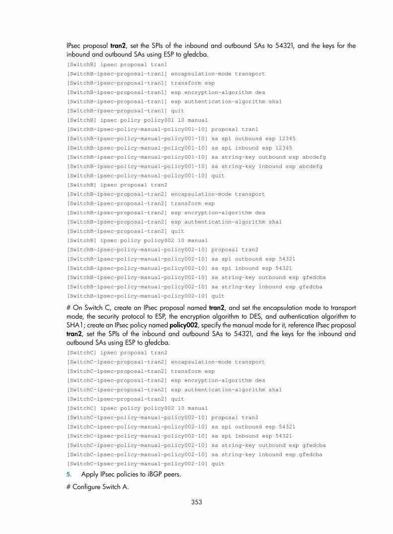
353
IPsec proposal tran2, set the SPIs of the inbound and outbound SAs to 54321, and the keys for the inbound and outbound SAs using ESP to gfedcba. [SwitchB] ipsec proposal tran1
[SwitchB-ipsec-proposal-tran1] encapsulation-mode transport
[SwitchB-ipsec-proposal-tran1] transform esp
[SwitchB-ipsec-proposal-tran1] esp encryption-algorithm des
[SwitchB-ipsec-proposal-tran1] esp authentication-algorithm sha1
[SwitchB-ipsec-proposal-tran1] quit
[SwitchB] ipsec policy policy001 10 manual
[SwitchB-ipsec-policy-manual-policy001-10] proposal tran1
[SwitchB-ipsec-policy-manual-policy001-10] sa spi outbound esp 12345
[SwitchB-ipsec-policy-manual-policy001-10] sa spi inbound esp 12345
[SwitchB-ipsec-policy-manual-policy001-10] sa string-key outbound esp abcdefg
[SwitchB-ipsec-policy-manual-policy001-10] sa string-key inbound esp abcdefg
[SwitchB-ipsec-policy-manual-policy001-10] quit
[SwitchB] ipsec proposal tran2
[SwitchB-ipsec-proposal-tran2] encapsulation-mode transport
[SwitchB-ipsec-proposal-tran2] transform esp
[SwitchB-ipsec-proposal-tran2] esp encryption-algorithm des
[SwitchB-ipsec-proposal-tran2] esp authentication-algorithm sha1
[SwitchB-ipsec-proposal-tran2] quit
[SwitchB] ipsec policy policy002 10 manual
[SwitchB-ipsec-policy-manual-policy002-10] proposal tran2
[SwitchB-ipsec-policy-manual-policy002-10] sa spi outbound esp 54321
[SwitchB-ipsec-policy-manual-policy002-10] sa spi inbound esp 54321
[SwitchB-ipsec-policy-manual-policy002-10] sa string-key outbound esp gfedcba
[SwitchB-ipsec-policy-manual-policy002-10] sa string-key inbound esp gfedcba
[SwitchB-ipsec-policy-manual-policy002-10] quit
# On Switch C, create an IPsec proposal named tran2, and set the encapsulation mode to transport mode, the security protocol to ESP, the encryption algorithm to DES, and authentication algorithm to SHA1; create an IPsec policy named policy002, specify the manual mode for it, reference IPsec proposal tran2, set the SPIs of the inbound and outbound SAs to 54321, and the keys for the inbound and outbound SAs using ESP to gfedcba. [SwitchC] ipsec proposal tran2
[SwitchC-ipsec-proposal-tran2] encapsulation-mode transport
[SwitchC-ipsec-proposal-tran2] transform esp
[SwitchC-ipsec-proposal-tran2] esp encryption-algorithm des
[SwitchC-ipsec-proposal-tran2] esp authentication-algorithm sha1
[SwitchC-ipsec-proposal-tran2] quit
[SwitchC] ipsec policy policy002 10 manual
[SwitchC-ipsec-policy-manual-policy002-10] proposal tran2
[SwitchC-ipsec-policy-manual-policy002-10] sa spi outbound esp 54321
[SwitchC-ipsec-policy-manual-policy002-10] sa spi inbound esp 54321
[SwitchC-ipsec-policy-manual-policy002-10] sa string-key outbound esp gfedcba
[SwitchC-ipsec-policy-manual-policy002-10] sa string-key inbound esp gfedcba
[SwitchC-ipsec-policy-manual-policy002-10] quit
5. Apply IPsec policies to iBGP peers.
# Configure Switch A.

354
[SwitchA] bgp 65008
[SwitchA-bgp] ipv6-family
[SwitchA-bgp-af-ipv6] peer 1::2 ipsec-policy policy001
[SwitchA-bgp-af-ipv6] quit
[SwitchA-bgp] quit
# Configure Switch B. [SwitchB] bgp 65008
[SwitchB-bgp] ipv6-family
[SwitchB-bgp-af-ipv6] peer 1::1 ipsec-policy policy001
[SwitchB-bgp-af-ipv6] quit
[SwitchB-bgp] quit
6. Apply IPsec policies to eBGP peers.
# Configure Switch C. [SwitchC] bgp 65009
[SwitchC-bgp] ipv6-family
[SwitchC-bgp-af-ipv6] peer ebgp ipsec-policy policy002
[SwitchC-bgp-af-ipv6] quit
[SwitchC-bgp] quit
# Configure Switch B. [SwitchB] bgp 65008
[SwitchB-bgp] ipv6-family
[SwitchB-bgp-af-ipv6] peer ebgp ipsec-policy policy002
[SwitchB-bgp-af-ipv6] quit
[SwitchB-bgp] quit
7. Verify the configuration.
# Display detailed IPv6 BGP peer information. [SwitchB] display bgp ipv6 peer verbose
BGP Peer is 1::1, remote AS 65008,
Type: IBGP link
BGP version 4, remote router ID 1.1.1.1
BGP current state: Established, Up for 00h01m51s
BGP current event: RecvKeepalive
BGP last state: OpenConfirm
Port: Local – 1029 Remote - 179
Configured: Active Hold Time: 180 sec Keepalive Time: 60 sec
Received : Active Hold Time: 180 sec
Negotiated: Active Hold Time: 180 sec
Peer optional capabilities:
Peer support bgp multi-protocol extended
Peer support bgp route refresh capability
Address family IPv4 Unicast: advertised and received
Received: Total 0 messages, Update messages 0
Sent: Total 0 messages, Update messages 0
Maximum allowed prefix number: 4294967295
Threshold: 75%
Minimum time between advertisement runs is 30 seconds
Optional capabilities:

355
Route refresh capability has been enabled
ORF advertise capability based on prefix (type 64):
Local: both
Negotiated: send
Peer Preferred Value: 0
IPsec policy name: policy001, SPI :12345
Routing policy configured:
No routing policy is configured
BGP Peer is 3::2, remote AS 65009,
Type: EBGP link
BGP version 4, remote router ID 3.3.3.3
BGP current state: Established, Up for 00h01m51s
BGP current event: RecvKeepalive
BGP last state: OpenConfirm
Port: Local – 1029 Remote - 179
Configured: Active Hold Time: 180 sec Keepalive Time: 60 sec
Received : Active Hold Time: 180 sec
Negotiated: Active Hold Time: 180 sec
Peer optional capabilities:
Peer support bgp multi-protocol extended
Peer support bgp route refresh capability
Address family IPv4 Unicast: advertised and received
Received: Total 0 messages, Update messages 0
Sent: Total 0 messages, Update messages 0
Maximum allowed prefix number: 4294967295
Threshold: 75%
Minimum time between advertisement runs is 30 seconds
Optional capabilities:
Route refresh capability has been enabled
ORF advertise capability based on prefix (type 64):
Local: both
Negotiated: send
Peer Preferred Value: 0
IPsec policy name: policy002, SPI :54321
Routing policy configured:
No routing policy is configured
The output shows that both iBGP and eBGP neighbor relationships have been established and all protocol packets are protected by IPsec.
Configuring BFD for IPv6 BGP Network requirements
As shown in Figure 118,
• Configure OSPFv3 as the IGP in AS 200.
• Establish two iBGP connections between Switch A and Switch C. When both links are working, Switch C adopts the link Switch A<—>Switch B<—>Switch C to exchange packets with network 1200::0/64. Configure BFD over the link. Then if the link fails, BFD can quickly detect the failure
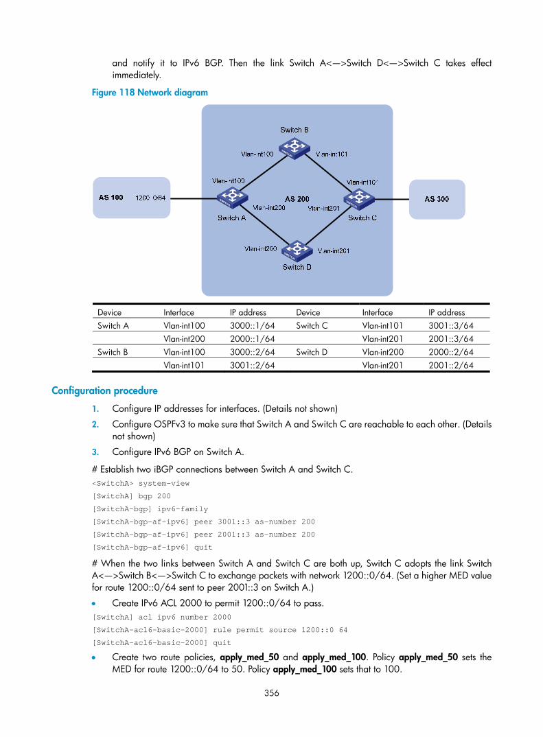
356
and notify it to IPv6 BGP. Then the link Switch A<—>Switch D<—>Switch C takes effect immediately.
Figure 118 Network diagram
Device Interface IP address Device Interface IP address Switch A Vlan-int100 3000::1/64 Switch C Vlan-int101 3001::3/64 Vlan-int200 2000::1/64 Vlan-int201 2001::3/64 Switch B Vlan-int100 3000::2/64 Switch D Vlan-int200 2000::2/64 Vlan-int101 3001::2/64 Vlan-int201 2001::2/64
Configuration procedure
1. Configure IP addresses for interfaces. (Details not shown)
2. Configure OSPFv3 to make sure that Switch A and Switch C are reachable to each other. (Details not shown)
3. Configure IPv6 BGP on Switch A.
# Establish two iBGP connections between Switch A and Switch C. <SwitchA> system-view
[SwitchA] bgp 200
[SwitchA-bgp] ipv6-family
[SwitchA-bgp-af-ipv6] peer 3001::3 as-number 200
[SwitchA-bgp-af-ipv6] peer 2001::3 as-number 200
[SwitchA-bgp-af-ipv6] quit
# When the two links between Switch A and Switch C are both up, Switch C adopts the link Switch A<—>Switch B<—>Switch C to exchange packets with network 1200::0/64. (Set a higher MED value for route 1200::0/64 sent to peer 2001::3 on Switch A.)
• Create IPv6 ACL 2000 to permit 1200::0/64 to pass. [SwitchA] acl ipv6 number 2000
[SwitchA-acl6-basic-2000] rule permit source 1200::0 64
[SwitchA-acl6-basic-2000] quit
• Create two route policies, apply_med_50 and apply_med_100. Policy apply_med_50 sets the MED for route 1200::0/64 to 50. Policy apply_med_100 sets that to 100.

357
[SwitchA] route-policy apply_med_50 permit node 10
[SwitchA-route-policy] if-match ipv6 address acl 2000
[SwitchA-route-policy] apply cost 50
[SwitchA-route-policy] quit
[SwitchA] route-policy apply_med_100 permit node 10
[SwitchA-route-policy] if-match ipv6 address acl 2000
[SwitchA-route-policy] apply cost 100
[SwitchA-route-policy] quit
• Apply routing policy apply_med_50 to routes outgoing to peer 3001::3, and apply routing policy apply_med_100 to routes outgoing to peer 2001::3.
[SwitchA] bgp 200
[SwitchA-bgp] ipv6-family
[SwitchA-bgp-af-ipv6] network 1200:: 64
[SwitchA-bgp-af-ipv6] peer 3001::3 route-policy apply_med_50 export
[SwitchA-bgp-af-ipv6] peer 2001::3 route-policy apply_med_100 export
# Configure BFD over the link to peer 3001::3 so that when the link Switch A<—>Switch B<—>Switch C fails, BFD can quickly detect the failure and notify it to IPv6 BGP, and then the link Switch A<—>Switch D<—>Switch C takes effect immediately. [SwitchA-bgp-af-ipv6] peer 3001::3 bfd
[SwitchA-bgp-af-ipv6] quit
[SwitchA-bgp] quit
4. Configure IPv6 BGP on Switch C. <SwitchC> system-view
[SwitchC] bgp 200
[SwitchC-bgp] ipv6-family
[SwitchC-bgp-af-ipv6] peer 3000::1 as-number 200
[SwitchC-bgp-af-ipv6] peer 3000::1 bfd
[SwitchC-bgp-af-ipv6] peer 2000::1 as-number 200
[SwitchC-bgp-af-ipv6] quit
[SwitchC-bgp] quit
5. Configure BFD parameters (you can use default BFD parameters instead).
# Configure Switch A. [SwitchA] bfd session init-mode active
[SwitchA] interface vlan-interface 100
• Configure the minimum interval for transmitting BFD control packets as 500 milliseconds. [SwitchA-Vlan-interface100] bfd min-transmit-interval 500
• Configure the minimum interval for receiving BFD control packets as 500 milliseconds. [SwitchA-Vlan-interface100] bfd min-receive-interval 500
• Configure the detect multiplier as 7. [SwitchA-Vlan-interface100] bfd detect-multiplier 7
[SwitchA-Vlan-interface100] quit
# Configure Switch C. [SwitchC] bfd session init-mode active
[SwitchC] interface vlan-interface 101
• Configure the minimum interval for transmitting BFD control packets as 500 milliseconds. [SwitchC-Vlan-interface101] bfd min-transmit-interval 500

358
• Configure the minimum interval for receiving BFD control packets as 500 milliseconds. [SwitchC-Vlan-interface101] bfd min-receive-interval 500
• Configure the detect multiplier as 7. [SwitchC-Vlan-interface101] bfd detect-multiplier 7
[SwitchC-Vlan-interface101] return
6. Verify the configuration.
The following operations are made on Switch C. Operations on Switch A and Switch B are similar and are not shown.
# Display detailed BFD session information. <SwitchC> display bfd session verbose
Total session number: 1 Up session number: 1 Init mode: Active
IPv6 Session working under Ctrl mode:
Local Discr: 17 Remote Discr: 13
Source IP: 3001::3
Destination IP: 3000::1
Session State: Up Interface: Vlan-interface101
Min Trans Inter: 500ms Act Trans Inter: 500ms
Min Recv Inter: 500ms Act Detect Inter: 3000ms
Recv Pkt Num: 57 Send Pkt Num: 53
Hold Time: 2200ms Connect Type: Direct
Running Up for: 00:00:06 Auth mode: none
Protocol: BGP6
Diag Info: No Diagnostic
The output shows that a BFD session is established between Switch A’s VLAN-interface 100 and Switch C’s VLAN-interface 101 and that BFD runs properly.
Display IPv6 peer information on Switch C, and you can see that the neighborship between Switch A and Switch C is established. <SwitchC> display bgp ipv6 peer
BGP local router ID : 1.1.1.1
Local AS number : 200
Total number of peers : 2 Peers in established state : 2
Peer AS MsgRcvd MsgSent OutQ PrefRcv Up/Down State
2000::1 200 7 10 0 0 00:01:05 Established
3000::1 200 7 10 0 0 00:01:34 Established
# Display route 1200::0/64 on Switch C, and you can see that Switch A and Switch C communicate through Switch B. <SwitchC> display ipv6 routing-table 1200::0 64 verbose
Routing Table :
Summary Count : 2
Destination : 1200:: PrefixLength : 64
NextHop : 3000::1 Preference : 255
RelayNextHop : 3001::2 Tag : 0H

359
Neighbor : 3000::1 ProcessID : 0
Interface : Vlan-interface101 Protocol : BGP4+
State : Active Adv Cost : 50
Tunnel ID : 0x0 Label : NULL
Age : 4538sec
Destination : 1200:: PrefixLength : 64
NextHop : 2000::1 Preference : 255
RelayNextHop : 2001::2 Tag : 0H
Neighbor : 2000::1 ProcessID : 0
Interface : Vlan-interface201 Protocol : BGP4+
State : Invalid Adv Cost : 100
Tunnel ID : 0x0 Label : NULL
Age : 4515sec
The output shows that Switch C has two routes to reach network 1200::0/64: Switch C<—>Switch B<—>Switch A, which is the currently active route; Switch C<—>Switch D<—>Switch A, which is the backup route.
# Enable BFD debugging on Switch C. <SwitchC> debugging bfd scm
<SwitchC> debugging bfd event
<SwitchC> debugging bgp bfd
<SwitchC> terminal monitor
<SwitchC> terminal debugging
# The following debugging information shows that Switch C can quickly detect the failure on Switch B. %Nov 5 11:42:24:172 2009 SwitchC BFD/5/BFD_CHANGE_FSM: Sess[3001::3/3000::1, 13/17,VLAN101,Ctrl], Sta: UP->DOWN, Diag: 1
%Nov 5 11:42:24:172 2009 SwitchC BGP/5/BGP_STATE_CHANGED: 3000::1 state is changed from ESTABLISHED to IDLE.
*Nov 5 11:42:24:187 2009 SwitchC RM/6/RMDEBUG: BGP_BFD: Recv BFD DOWN msg, Src IP 3001::3, Dst IP 3000::1, Instance ID 0.
*Nov 5 11:42:24:187 2009 SwitchC RM/6/RMDEBUG: BGP_BFD: Reset BGP session 3000::1 for BFD session down.
*Nov 5 11:42:24:187 2009 SwitchC RM/6/RMDEBUG: BGP_BFD: Send DELETE msg to BFD, Connection type DIRECT, Src IP 3001::3, Dst IP 3000::1, Instance ID 0.
# Display route 1200::0/64 on Switch C, and you can see that Switch A and Switch C communicate through Switch D. <SwitchC> display ipv6 routing-table 1200::0 64 verbose
Routing Table :
Summary Count : 1
Destination : 1200:: PrefixLength : 64
NextHop : 2000::1 Preference : 255
RelayNextHop : 2001::2 Tag : 0H
Neighbor : 2000::1 ProcessID : 0
Interface : Vlan-interface201 Protocol : BGP4+
State : Active Adv Cost : 100
Tunnel ID : 0x0 Label : NULL
Age : 4635sec

360
The output shows that Switch C has one route to reach network 1200::0/64, that is, Switch C<—>Switch D<—>Switch A.
Troubleshooting IPv6 BGP configuration
IPv6 BGP peer relationship not established Symptom
Display BGP peer information by using the display bgp ipv6 peer command. The state of the connection to the peer cannot become established.
Analysis
To become IPv6 BGP peers, any two routers must establish a TCP session using port 179 and exchange open messages successfully.
Processing steps
1. Use the display current-configuration command to check that the peer’s AS number is correct.
2. Use the display bgp ipv6 peer command to check that the peer’s IPv6 address is correct.
3. If a loopback interface is used, check that the loopback interface is specified with the peer connect-interface command.
4. If the peer is not directly connected, check that the peer ebgp-max-hop command is configured.
5. Check that a valid route to the peer is available.
6. Use the ping command to check the connectivity to the peer.
7. Use the display tcp ipv6 status command to check the TCP connection.
8. Check whether an ACL for disabling TCP port 179 is configured.

361
Routing policy configuration
Routing policies are used to receive, advertise, and redistribute only specific routes and modify the attributes of some routes.
NOTE:
• Routing policy in this chapter involves both IPv4 routing policy and IPv6 routing policy.
• The 3600 v2 SI Switch Series does not support OSPF, BGP, IS-IS, OSPFv3, IPv6 BGP, or IPv6 IS-IS.
Introduction to routing policy A routing policy is used to filter routes when they are received, advertised, or redistributed and modify the attributes of some routes.
Routing policy application A routing policy has the following applications:
• Filters advertised routes
• Filters received routes
• Filters redistributed routes
• Modifies or sets the attributes of some routes
Routing policy implementation To configure a routing policy, you must do the following:
1. Define some filters based on the attributes of routing information, such as destination address, and the advertising router’s address.
2. Apply the filters to the routing policy.
You can use multiple filters to define match criteria. For detailed information, see “Filters.”
Filters You can use the following types of filters: ACL, IP prefix list, AS path ACL, community list, extended community list, and routing policy.
ACL
ACL involves IPv4 ACL and IPv6 ACL. An ACL is configured to match the destinations or next hops of routing information.
For more information about ACL, see ACL and QoS Configuration Guide.
IP prefix list
IP prefix list involves IPv4 prefix list and IPv6 prefix list.

362
An IP prefix list is configured to match the destination address of routing information. You can use the gateway option to allow only routing information from certain routers to be received. For gateway option information, see the chapters “RIP configuration” and “OSPF configuration.”
An IP prefix list, identified by name, can comprise multiple items. Each item, identified by an index number, can specify a prefix range to match. An item with a smaller index number is matched first. If one item is matched, the IP prefix list is passed, and the packet will not go to the next item.
AS-PATH list
An AS-PATH list, configured based on the BGP AS PATH attribute, can only be used to match BGP routing information.
For more information about AS-PATH list, see the chapter “BGP configuration.”
Community list
A community list, configured based on the BGP community attribute, can only be used to match BGP routing information.
For more information about community list, see the chapter “BGP configuration.”
Extended community list
An extended community list, configured based on the BGP extended community attribute (Route-Target for VPN and Source of Origin), can only be used to match BGP routing information.
Routing policy
A routing policy is used to match routing information and modify the attributes of permitted routes. It can reference the filters to define its own match criteria.
A routing policy can comprise multiple nodes, which are in logic OR relationship. Each routing policy node is a match unit, and a node with a smaller number is matched first. Once a node is matched, the routing policy is passed and the packet will not go to the next node.
A routing policy node comprises a set of if-match, apply, and continue clauses.
• The if-match clauses define the match criteria. The matching objects are some attributes of routing information. The if-match clauses of a routing policy node is in a logical AND relationship. A packet must match all the if-match clauses of the node to pass it.
• The apply clauses of the node specify the actions to be taken on the permitted packets, such as modifying a route attribute.
• The continue clause specifies the next routing policy node to be matched. With this clause configured, when a route matches the current routing policy node, it continues to match against the specified next node in the same routing policy. The continue clause combines the if-match and apply clauses of the two nodes to improve flexibility of the routing policy.
Use the following guidelines when configuring if-match, apply, and continue clauses:
• If you want to implement route filtering only, you do not need to configure apply clauses.
• If you do not configure any if-match clauses for a permit-mode node, the node permits all routes to pass.
• Configure a permit-mode node containing no if-match or apply clauses behind multiple deny-mode nodes to allow unmatched routes to pass.

363
Routing policy configuration task list Complete the following tasks to configure a routing policy:
Task
Defining filters
Defining an IP-prefix list
Defining an AS path list
Defining a community list
Defining an extended community list
Configuring a routing policy
Creating a routing policy
Defining if-match clauses
Defining apply clauses
Defining a continue clause
Defining filters
Prerequisites Before configuring this task, you must determine IP-prefix list name, matching address range, and extcommunity list sequence number.
Defining an IP-prefix list Define an IPv4 prefix list
Identified by name, an IPv4 prefix list can comprise multiple items. Each item specifies a prefix range to match and is identified by an index number.
An item with a smaller index number is matched first. If one item is matched, the IP prefix list is passed, and the routing information will not go to the next item.
Follow these steps to define an IPv4 prefix list:
To do… Use the command… Remarks
Enter system view system-view —
Define an IPv4 prefix list
ip ip-prefix ip-prefix-name [ index index-number ] { deny | permit } ip-address mask-length [ greater-equal min-mask-length ] [ less-equal max-mask-length ]
Required
Not defined by default.
NOTE:
If all the items are set to the deny mode, no routes can pass the IPv4 prefix list. You must define the permit0.0.0.0 0 less-equal 32 item following multiple deny items to allow other IPv4 routing information to pass.
For example, the following configuration filters routes 10.1.0.0/16, 10.2.0.0/16, and 10.3.0.0/16, but allows other routes to pass. <Sysname> system-view

364
[Sysname] ip ip-prefix abc index 10 deny 10.1.0.0 16
[Sysname] ip ip-prefix abc index 20 deny 10.2.0.0 16
[Sysname] ip ip-prefix abc index 30 deny 10.3.0.0 16
[Sysname] ip ip-prefix abc index 40 permit 0.0.0.0 0 less-equal 32
Define an IPv6 prefix list
Identified by name, each IPv6 prefix list can comprise multiple items. Each item specifies a prefix range to match and is identified by an index number.
An item with a smaller index number is matched first. If one item is matched, the IPv6 prefix list is passed, and the routing information will not go to the next item.
Follow these steps to define an IPv6 prefix list:
To do… Use the command… Remarks
Enter system view system-view —
Define an IPv6 prefix list
ip ipv6-prefix ipv6-prefix-name [ index index-number ] { deny | permit } ipv6-address prefix-length [ greater-equal min-prefix-length ] [ less-equal max-prefix-length ]
Required
Not defined by default.
NOTE:
If all items are set to the deny mode, no routes can pass the IPv6 prefix list. You must define the permit ::0 less-equal 128 item following multiple deny items to allow other IPv6 routing information to pass.
For example, the following configuration filters routes 2000:1::/48, 2000:2::/48, and 2000:3::/48, but allows other routes to pass. <Sysname> system-view
[Sysname] ip ipv6-prefix abc index 10 deny 2000:1:: 48
[Sysname] ip ipv6-prefix abc index 20 deny 2000:2:: 48
[Sysname] ip ipv6-prefix abc index 30 deny 2000:3:: 16
[Sysname] ip ipv6-prefix abc index 40 permit :: 0 less-equal 128
Defining an AS path list You can define multiple items for an AS path list that is identified by number. The relationship between items is logical OR. If a route matches one of these items, it passes the AS path list.
Follow these steps to define an AS path list:
To do… Use the command… Remarks Enter system view system-view —
Define an AS path ACL ip as-path as-path-number { deny | permit } regular-expression
Required
Not defined by default.
Defining a community list You can define multiple items for a community list that is identified by number. During matching, the relationship between items is logic OR. If routing information matches one of these items, it passes the community list.

365
Follow these steps to define a community list:
To do… Use the command… Remarks
Enter system view system-view —
Define a community list
Define a basic community list
ip community-list { basic-comm-list-num | basic comm-list-name } { deny | permit } [ community-number-list ] [ internet | no-advertise | no-export | no-export-subconfed ] *
Required to define either
Not defined by default. Define an
advanced community list
ip community-list { adv-comm-list-num | advanced comm-list-name } { deny | permit } regular-expression
Defining an extended community list You can define multiple items for an extended community list that is identified by number. During matching, the relation between items is logic OR. If routing information matches one of these items, it passes the extended community list.
Follow these steps to define an extended community list:
To do… Use the command… Remarks
Enter system view system-view —
Define an extended community list
ip extcommunity-list ext-comm-list-number { deny | permit } { rt route-target | soo site-of-origin }&<1-16>
Required
Not defined by default
Configuring a routing policy A routing policy is used to filter routing information and modify attributes of matching routing information. The match criteria of a routing policy can be configured by referencing the appropriate filters.
A routing policy can comprise multiple nodes, and each routing policy node contains the following:
• if-match clauses—Define the match criteria that routing information must satisfy. The matching objects are some attributes of routing information.
• apply clauses—Specify the actions to be taken on routing information that has satisfied the match criteria, such as route attribute modification.
• continue clauses—Specify the next routing policy node to be matched. With this clause configured, when a route matches the current routing policy node, it continues to match against the specified next node in the same routing policy.
Prerequisites Before configuring this task, you need to configure the filters and routing protocols. You also need to decide on the name of the routing policy and node numbers, match criteria, and attributes to be modified.
Creating a routing policy Follow these steps to create a routing policy:

366
To do… Use the command… Remarks
Enter system view system-view —
Create a routing policy, specify a node for it, and enter routing policy view
route-policy route-policy-name { deny | permit } node node-number
Required
NOTE:
• If a routing policy node has the permit keyword specified, routing information matching all the if-matchclauses of the node will be handled using the apply clauses of this node, without needing to match against the next node. If routing information does not match the node, it goes to the next node for a match.
• If a routing policy node has the deny keyword specified, the apply clauses of the node is not executed.When routing information matches all the if-match clauses of the node, it cannot pass the node, or goto the next node. If route information cannot match all the if-match clauses of the node, it goes to the next node for a match.
• When a routing policy has more than one node, at least one node must be configured with the permitkeyword. If the routing policy is used to filter routing information, routing information that does not meetany node cannot pass the routing policy. If all nodes of the routing policy are set with the deny keyword,no routing information can pass it.
Defining if-match clauses Follow these steps to define if-match clauses for a routing policy:
To do… Use the command… Remarks
Enter system view system-view —
Enter routing policy view route-policy route-policy-name { deny | permit } node node-number Required
Define match criteria for IPv4 routes
Match IPv4 routing information specified in the ACL
if-match acl acl-number Optional
Not configured by default. Match IPv4 routing
information specified in the IP prefix list
if-match ip-prefix ip-prefix-name
Match IPv4 routing information whose next hop or source is specified in the ACL or IP prefix list
if-match ip { next-hop | route-source } { acl acl-number | ip-prefix ip-prefix-name }
Optional
Not configured by default.
Match IPv6 routing information whose next hop or source is specified in the ACL or IP prefix list
if-match ipv6 { address | next-hop | route-source } { acl acl-number | prefix-list ipv6-prefix-name }
Optional
Not configured by default.
Match BGP routing information whose AS path attribute is specified in the AS path lists
if-match as-path AS-PATH-number&<1-16>
Optional
Not configured by default.

367
To do… Use the command… Remarks
Match BGP routing information whose community attribute is specified in the community lists
if-match community { { basic-community-list-number | comm-list-name } [ whole-match ] | adv-community-list-number }&<1-16>
Optional
Not configured by default.
Match routes having the specified cost if-match cost value Optional
Not configured by default.
Match BGP routing information whose extended community attribute is specified in the extended community list(s)
if-match extcommunity ext-comm-list-number&<1-16>
Optional
Not configured by default.
Match routing information having specified outbound interface(s)
if-match interface { interface-type interface-number }&<1-16>
Optional
Not configured by default.
Match routing information having the specified route type
if-match route-type { external-type1 | external-type1or2 | external-type2 | internal | is-is-level-1 | is-is-level-2 | nssa-external-type1 | nssa-external-type1or2 | nssa-external-type2 } *
Optional
Not configured by default.
Match RIP, OSPF, and IS-IS routing information having the specified tag value if-match tag value
Optional
Not configured by default.
NOTE:
• The if-match clauses of a routing policy node are in logic AND relationship. Routing information mustsatisfy all of its if-match clauses before being executed with its apply clauses. If an if-match commandexceeds the maximum length, multiple identical if-match clauses are generated. These clauses are in logical OR relationship. Routing information only needs to match one of them.
• You can specify any number of if-match clauses for a routing policy node. If no if-match clause is specified, and the routing policy node is in permit mode, all routing information can pass the node. If itis in deny mode, no routing information can pass it.
• If the ACL referenced by an if-match clause does not exist, the clause is always satisfied; if no rules of thereferenced ACL are matched or the matching rule is inactive, the clause is not satisfied.
• An ACL specified in an if-match clause must be a non-VPN ACL.
• The if-match commands for matching IPv4 destination, next hop, and source address are different fromthose for matching IPv6 ones.
• BGP does not support criteria for matching against outbound interfaces of routing information.
Defining apply clauses Follow these steps to define apply clauses for a routing policy:
To do… Use the command… Remarks
Enter system view system-view —

368
To do… Use the command… Remarks
Enter routing policy view route-policy route-policy-name { deny | permit } node node-number
Required
Not created by default.
Set the AS-PATH attribute for BGP routing information
apply as-path as-number&<1-10> [ replace ]
Optional
Not set by default.
Delete the community attribute of BGP routing information using the community list
apply comm-list { comm-list-number | comm-list-name } delete
Optional
Not configured by default.
Set the community attribute for BGP routing information
apply community { none | additive | { community-number&<1-16> | aa:nn&<1-16> | internet | no-advertise | no-export | no-export-subconfed } * [ additive ] }
Optional
Not set by default.
Set a cost for routing information apply cost [ + | - ] value Optional
Not set by default.
Set a cost type for routing information
apply cost-type [ external | internal | type-1 | type-2 ]
Optional
Not set by default.
Set the extended community attribute for BGP routing
apply extcommunity { { rt route-target }&<1-16> [ additive ] | soo site-of-origin additive }
Optional
Not set by default.
Set the next hop for IPv4 routes apply ip-address next-hop ip-address
Optional
Not set by default.
The setting does not apply to redistributed routing information.
Inject routing information to a specified ISIS level
apply isis { level-1 | level-1-2 | level-2 }
Optional
Not configured by default.
Set the local preference for BGP routing information apply local-preference preference
Optional
Not set by default.
Set the origin attribute for BGP routing information
apply origin { egp as-number | igp | incomplete }
Optional
Not set by default.
Set the preference for the routing protocol apply preference preference
Optional
Not set by default.
Set a preferred value for BGP routing information
apply preferred-value preferred-value
Optional
Not set by default.
Set a tag value for RIP, OSPF, or IS-IS routing information apply tag value
Optional
Not set by default.
Configure FRR
apply fast-reroute { backup-interface interface-type interface-number [ backup-nexthop ip-address ] }
Optional
Not configured by default.

369
NOTE:
• The difference between IPv4 and IPv6 apply clauses is the command for setting the next hop for routinginformation.
• The apply ip-address next-hop and apply ipv6 next-hop commands do not apply to redistributed IPv4and IPv6 routes, respectively.
Defining a continue clause Follow these steps to define a continue clause for a routing policy:
To do… Use the command… Remarks
Enter system view system-view —
Create a routing policy and enter routing policy view
route-policy route-policy-name { deny | permit } node node-number
Required
Not created by default.
Specify the next routing policy node to be matched continue [ node-number ]
Optional
Not configured by default.
The node number specified must be larger that the current node number.
NOTE:
• If you configure the same type of apply clauses that set different values (including the apply communityand apply extcommunity clauses with the additive keyword) on nodes that are combined by the continue clause, the apply clause configured on the last matching node takes effect.
• If you configure the apply community clause for multiple nodes that are combined by the continue clause, the apply comm-list delete clause configured on the current node cannot delete the communityattributes of preceding nodes.
Displaying and maintaining the routing policy To do… Use the command… Remarks Display BGP AS-PATH list information
display ip as-path [ as-path-number ] [ | { begin | exclude | include } regular-expression ]
Available in any view
Display BGP community list information
display ip community-list [ basic-community-list-number | adv-community-list-number | comm-list-name ] [ | { begin | exclude | include } regular-expression ]
Display BGP extended community list information
display ip extcommunity-list [ ext-comm-list-number ] [ | { begin | exclude | include } regular-expression ]
Display IPv4 prefix list statistics display ip ip-prefix [ ip-prefix-name ] [ | { begin | exclude | include } regular-expression ]
Display IPv6 prefix list statistics display ip ipv6-prefix [ ipv6-prefix-name ] [ | { begin | exclude | include } regular-expression ]

370
To do… Use the command… Remarks
Display routing policy information display route-policy [ route-policy-name ] [ | { begin | exclude | include } regular-expression ]
Clear IPv4 prefix list statistics reset ip ip-prefix [ ip-prefix-name ] Available in user view Clear IPv6 prefix list statistics reset ip ipv6-prefix [ ipv6-prefix-name ]
Routing policy configuration examples
Applying a routing policy to IPv4 route redistribution Network requirements
As shown in Figure 119, Switch B exchanges routing information with Switch A using OSPF, and with Switch C using IS-IS.
On Switch B, enable route redistribution from IS-IS to OSPF, and apply a routing policy to set the cost of route 172.17.1.0/24 to 100 and the tag of route 172.17.2.0/24 to 20.
Figure 119 Network diagram
Configuration procedure
1. Specify IP addresses for interfaces. (Details not shown)
2. Configure IS-IS.
# Configure Switch C. <SwitchC> system-view
[SwitchC] isis
[SwitchC-isis-1] is-level level-2
[SwitchC-isis-1] network-entity 10.0000.0000.0001.00
[SwitchC-isis-1] quit
[SwitchC] interface vlan-interface 200
[SwitchC-Vlan-interface200] isis enable
[SwitchC-Vlan-interface200] quit
[SwitchC] interface vlan-interface 201
[SwitchC-Vlan-interface201] isis enable

371
[SwitchC-Vlan-interface201] quit
[SwitchC] interface vlan-interface 202
[SwitchC-Vlan-interface202] isis enable
[SwitchC-Vlan-interface202] quit
[SwitchC] interface vlan-interface 203
[SwitchC-Vlan-interface203] isis enable
[SwitchC-Vlan-interface203] quit
# Configure Switch B. <SwitchB> system-view
[SwitchB] isis
[SwitchB-isis-1] is-level level-2
[SwitchB-isis-1] network-entity 10.0000.0000.0002.00
[SwitchB-isis-1] quit
[SwitchB] interface vlan-interface 200
[SwitchB-Vlan-interface200] isis enable
[SwitchB-Vlan-interface200] quit
3. Configure OSPF and route redistribution.
# Configure OSPF on Switch A. <SwitchA> system-view
[SwitchA] ospf
[SwitchA-ospf-1] area 0
[SwitchA-ospf-1-area-0.0.0.0] network 192.168.1.0 0.0.0.255
[SwitchA-ospf-1-area-0.0.0.0] quit
[SwitchA-ospf-1] quit
# On Switch B, configure OSPF and enable route redistribution from IS-IS. [SwitchB] ospf
[SwitchB-ospf-1] area 0
[SwitchB-ospf-1-area-0.0.0.0] network 192.168.1.0 0.0.0.255
[SwitchB-ospf-1-area-0.0.0.0] quit
[SwitchB-ospf-1] import-route isis 1
[SwitchB-ospf-1] quit
# Display the OSPF routing table on Switch A to view redistributed routes. [SwitchA] display ospf routing
OSPF Process 1 with Router ID 192.168.1.1
Routing Tables
Routing for Network
Destination Cost Type NextHop AdvRouter Area
192.168.1.0/24 1562 Stub 192.168.1.1 192.168.1.1 0.0.0.0
Routing for ASEs
Destination Cost Type Tag NextHop AdvRouter
172.17.1.0/24 1 Type2 1 192.168.1.2 192.168.2.2
172.17.2.0/24 1 Type2 1 192.168.1.2 192.168.2.2
172.17.3.0/24 1 Type2 1 192.168.1.2 192.168.2.2
192.168.2.0/24 1 Type2 1 192.168.1.2 192.168.2.2

372
Total Nets: 5
Intra Area: 1 Inter Area: 0 ASE: 4 NSSA: 0
4. Configure filtering lists.
# Configure ACL 2002 to permit route 172.17.2.0/24. [SwitchB] acl number 2002
[SwitchB-acl-basic-2002] rule permit source 172.17.2.0 0.0.0.255
[SwitchB-acl-basic-2002] quit
# Configure IP prefix list prefix-a to permit route 172.17.1.0/24. [SwitchB] ip ip-prefix prefix-a index 10 permit 172.17.1.0 24
5. Configure a routing policy. [SwitchB] route-policy isis2ospf permit node 10
[SwitchB-route-policy] if-match ip-prefix prefix-a
[SwitchB-route-policy] apply cost 100
[SwitchB-route-policy] quit
[SwitchB] route-policy isis2ospf permit node 20
[SwitchB-route-policy] if-match acl 2002
[SwitchB-route-policy] apply tag 20
[SwitchB-route-policy] quit
[SwitchB] route-policy isis2ospf permit node 30
[SwitchB-route-policy] quit
6. Apply the routing policy to route redistribution.
# On Switch B, apply the routing policy when redistributing routes. [SwitchB] ospf
[SwitchB-ospf-1] import-route isis 1 route-policy isis2ospf
[SwitchB-ospf-1] quit
# Display the OSPF routing table on Switch A. The cost of route 172.17.1.0/24 is 100, the tag of route 172.17.1.0/24 is 20. [SwitchA] display ospf routing
OSPF Process 1 with Router ID 192.168.1.1
Routing Tables
Routing for Network
Destination Cost Type NextHop AdvRouter Area
192.168.1.0/24 1 Transit 192.168.1.1 192.168.1.1 0.0.0.0
Routing for ASEs
Destination Cost Type Tag NextHop AdvRouter
172.17.1.0/24 100 Type2 1 192.168.1.2 192.168.2.2
172.17.2.0/24 1 Type2 20 192.168.1.2 192.168.2.2
172.17.3.0/24 1 Type2 1 192.168.1.2 192.168.2.2
192.168.2.0/24 1 Type2 1 192.168.1.2 192.168.2.2
Total Nets: 5
Intra Area: 1 Inter Area: 0 ASE: 4 NSSA: 0

373
Applying a routing policy to IPv6 route redistribution Network requirements
As shown in Figure 120:
• Enable RIPng on Switch A and Switch B.
• On Switch A, configure three static routes, and apply a routing policy to static route redistribution to permit routes 20::0/32 and 40::0/32, and deny route 30::0/32.
• Display RIPng routing table information on Switch B to verify the configuration.
Figure 120 Network diagram
Configuration procedure
1. Configure Switch A.
# Configure IPv6 addresses for VLAN-interface 100 and VLAN-interface 200. <SwitchA> system-view
[SwitchA] ipv6
[SwitchA] interface vlan-interface 100
[SwitchA-Vlan-interface100] ipv6 address 10::1 32
[SwitchA-Vlan-interface100] quit
[SwitchA] interface vlan-interface 200
[SwitchA-Vlan-interface200] ipv6 address 11::1 32
[SwitchA-Vlan-interface200] quit
# Enable RIPng on VLAN-interface 100. [SwitchA] interface vlan-interface 100
[SwitchA-Vlan-interface100] ripng 1 enable
[SwitchA-Vlan-interface100] quit
# Configure three static routes—with next hop 11::2—and make sure that they are active. [SwitchA] ipv6 route-static 20:: 32 11::2
[SwitchA] ipv6 route-static 30:: 32 11::2
[SwitchA] ipv6 route-static 40:: 32 11::2
# Configure a routing policy. [SwitchA] ip ipv6-prefix a index 10 permit 30:: 32
[SwitchA] route-policy static2ripng deny node 0
[SwitchA-route-policy] if-match ipv6 address prefix-list a
[SwitchA-route-policy] quit
[SwitchA] route-policy static2ripng permit node 10
[SwitchA-route-policy] quit
# Enable RIPng and apply the routing policy to static route redistribution. [SwitchA] ripng

374
[SwitchA-ripng-1] import-route static route-policy static2ripng
2. Configure Switch B.
# Configure the IPv6 address for VLAN-interface 100. [SwitchB] ipv6
[SwitchB] interface vlan-interface 100
[SwitchB-Vlan-interface100] ipv6 address 10::2 32
# Enable RIPng on VLAN-interface 100. [SwitchB-Vlan-interface100] ripng 1 enable
[SwitchB-Vlan-interface100] quit
# Enable RIPng. [SwitchB] ripng
# Display RIPng routing table information. [SwitchB-ripng-1] display ripng 1 route
Route Flags: A - Aging, S - Suppressed, G - Garbage-collect
----------------------------------------------------------------
Peer FE80::7D58:0:CA03:1 on Vlan-interface 100
Dest 10::/32,
via FE80::7D58:0:CA03:1, cost 1, tag 0, A, 18 Sec
Dest 20::/32,
via FE80::7D58:0:CA03:1, cost 1, tag 0, A, 8 Sec
Dest 40::/32,
via FE80::7D58:0:CA03:1, cost 1, tag 0, A, 3 Sec
Applying a routing policy to filter received BGP routes Network requirements
As shown in Figure 121, all the switches run BGP. Switch C establishes eBGP connections with other switches.
Configure a routing policy on Switch D to reject routes from AS 200.
Figure 121 Network diagram
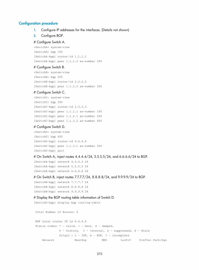
375
Configuration procedure
1. Configure IP addresses for the interfaces. (Details not shown)
2. Configure BGP.
# Configure Switch A. <SwitchA> system-view
[SwitchA] bgp 100
[SwitchA-bgp] router-id 1.1.1.1
[SwitchA-bgp] peer 1.1.1.2 as-number 300
# Configure Switch B. <SwitchB> system-view
[SwitchB] bgp 200
[SwitchB-bgp] router-id 2.2.2.2
[SwitchB-bgp] peer 1.1.2.2 as-number 300
# Configure Switch C. <SwitchC> system-view
[SwitchC] bgp 300
[SwitchC-bgp] router-id 3.3.3.3
[SwitchC-bgp] peer 1.1.1.1 as-number 100
[SwitchC-bgp] peer 1.1.2.1 as-number 200
[SwitchC-bgp] peer 1.1.3.2 as-number 400
# Configure Switch D. <SwitchD> system-view
[SwitchD] bgp 400
[SwitchD-bgp] router-id 4.4.4.4
[SwitchD-bgp] peer 1.1.3.1 as-number 300
[SwitchD-bgp] quit
# On Switch A, inject routes 4.4.4.4/24, 5.5.5.5/24, and 6.6.6.6/24 to BGP. [SwitchA-bgp] network 4.4.4.4 24
[SwitchA-bgp] network 5.5.5.5 24
[SwitchA-bgp] network 6.6.6.6 24
# On Switch B, inject routes 7.7.7.7/24, 8.8.8.8/24, and 9.9.9.9/24 to BGP. [SwitchB-bgp] network 7.7.7.7 24
[SwitchB-bgp] network 8.8.8.8 24
[SwitchB-bgp] network 9.9.9.9 24
# Display the BGP routing table information of Switch D. [SwitchD-bgp] display bgp routing-table
Total Number of Routes: 6
BGP Local router ID is 4.4.4.4
Status codes: * - valid, > - best, d - damped,
h - history, i - internal, s - suppressed, S - Stale
Origin : i - IGP, e - EGP, ? - incomplete
Network NextHop MED LocPrf PrefVal Path/Ogn

376
*> 4.4.4.0/24 1.1.3.1 0 300 100i
*> 5.5.5.0/24 1.1.3.1 0 300 100i
*> 6.6.6.0/24 1.1.3.1 0 300 100i
*> 7.7.7.0/24 1.1.3.1 0 300 200i
*> 8.8.8.0/24 1.1.3.1 0 300 200i
*> 9.9.9.0/24 1.1.3.1 0 300 200i
The output shows that Switch D has learned routes 4.4.4.0/24, 5.5.5.0/24, and 6.6.6.0/24 from AS 100 and 7.7.7.0/24, 8.8.8.0/24, and 9.9.9.0/24 from AS 200.
3. Configure Switch D to reject routes from AS 200.
# Configure AS_PATH list 1. [SwitchD] ip as-path 1 permit .*200.*
# Create routing policy rt1 with node 1, and specify the match mode as deny to deny routes from AS 200. [SwitchD] route-policy rt1 deny node 1
[SwitchD-route-policy] if-match as-path 1
[SwitchD-route-policy] quit
# Create routing policy rt1 with node 10, and specify the match mode as permit to permit routes from other ASs. [SwitchD] route-policy rt1 permit node 10
[SwitchD-route-policy] quit
# On Switch D, specify routing policy rt1 to filter routes received from peer 1.1.3.1. [SwitchD] bgp 400
[SwitchD-bgp] peer 1.1.3.1 route-policy rt1 import
# Display the BGP routing table information of Switch D. [SwitchD-bgp] display bgp routing-table
Total Number of Routes: 3
BGP Local router ID is 4.4.4.4
Status codes: * - valid, > - best, d - damped,
h - history, i - internal, s - suppressed, S - Stale
Origin : i - IGP, e - EGP, ? - incomplete
Network NextHop MED LocPrf PrefVal Path/Ogn
*> 4.4.4.0/24 1.1.3.1 0 300 100i
*> 5.5.5.0/24 1.1.3.1 0 300 100i
*> 6.6.6.0/24 1.1.3.1 0 300 100i
The output shows that Switch D has learned only routes 4.4.4.0/24, 5.5.5.0/24, and 6.6.6.0/24 from AS 100.

377
Troubleshooting routing policy configuration
IPv4 routing information filtering failure Symptom
The routing protocol is running properly, but filtering routing information failed.
Analysis
At least one item of the IP prefix list must be configured as permit mode, and at least one node in the routing policy must be configured as permit mode.
Solution
1. Use the display ip ip-prefix command to display IP prefix list information.
2. Use the display route-policy command to display routing policy information.
IPv6 routing information filtering failure Symptom
The routing protocol is running properly, but filtering routing information failed.
Analysis
At least one item of the IPv6 prefix list must be configured as permit mode, and at least one node of the routing policy must be configured as permit mode.
Solution
1. Use the display ip ipv6-prefix command to display IP prefix list information.
2. Use the display route-policy command to display routing policy information.

378
Policy-based routing configuration
Introduction to PBR Policy-based routing (PBR) is a routing mechanism based on user-defined policies. Different from the traditional destination-based routing mechanism, PBR enables you to use a policy (based on the source address or other criteria) to route packets.
In general, PBR takes precedence over destination-based routing. PBR is applied to the packets matching the specified criteria, and other packets are forwarded through destination-based routing.
This Switch Series supports the following PBR implementation methods:
• Using a PBR policy
The PBR policy allows you to specify the next hop, priority, and default next hop to guide the forwarding of packets that match specific ACLs. Only IPv4 unicast PBR is supported.
You can modify ACL rules to implement flexible service control.
NOTE:
• If the configured next hop in the PBR policy does not exist, the matching packet is forwarded accordingto the routing table.
• If a default next hop is configured in the PBR policy, destination-based routing takes precedence over PBR.
• Using a QoS policy
The QoS policy uses QoS traffic classification to define matching criteria, and uses the redirection action of traffic behavior to guide packet forwarding. This implementation method supports both IPv4 and IPv6 unicast PBR.
PBR modes According to the objects to which the PBR applies, PBR involves local PBR and interface PBR.
• Local PBR applies to locally generated packets only, such as the ICMP packets generated by using the ping command.
• Interface PBR applies to packets forwarded through the interface only.
In most cases, interface PBR is implemented to meet the forwarding and security requirements.
NOTE:
The term Layer 3 Ethernet interface in this chapter refers to Layer 3 interfaces, including VLAN interfacesand route mode (or Layer 3) Ethernet ports. You can set an Ethernet port to operate in route mode by usingthe port link-mode route command (see Layer 2—LAN Switching Configuration Guide).

379
Concepts Policy
A policy is used to route IP packets. A policy can consist of one or multiple nodes.
Node
A node is identified by a node number. The node with the smallest node number has the highest priority.
A policy node consists of if-match and apply clauses. An if-match clause specifies a match criterion on a node, and an apply clause specifies an action to be taken on packets.
The action to be taken on matched packets depends on the match mode, which can be permit or deny.
if-match clause
This Switch Series supports the if-match acl clause.
You can specify only one if-match clause of each type in a policy node.
apply clause
This Switch Series supports three apply clauses, apply ip-precedence, apply ip-address next-hop, and apply ip-address default next-hop.
NOTE:
The apply ip-address default next-hop command takes effect only when no next hop is defined, or the defined next hop is invalid and the destination address does not match any route in the routing table.
Relationship between the match mode and clauses
Table 7 Relationship between the match mode and the clauses
If a packet… Then…
In permit mode In deny mode
Matches all the if-match clauses on a policy node
The apply clause is executed, and the packet will not go to the next policy node for a match.
The apply clause is not executed, the packets will not go to the next policy node for a match, and will be forwarded according to the routing table.
Fails to match an if-match clause on the policy node
The apply clause is not executed, and the packet will go to the next policy node for a match.
The apply clause is not executed, and the packet will go to the next policy node for a match.
The nodes of a policy are in an OR relationship. If a packet matches a node, it passes the policy; if the packet does not match any node of the policy, it fails to pass the policy and is forwarded according to the routing table.
QoS mode The QoS policy uses QoS traffic classification to define matching criteria, and uses the redirection action of traffic behavior to guide packet forwarding in order to implement flexible routing.
PBR takes precedence over destination-based routing. If a packet meets the match criteria, PBR applies; otherwise, destination-based routing applies.

380
NOTE:
For more information about QoS policies, see ACL and QoS Configuration Guide.
Configuring PBR (using a PBR policy)
Defining a policy Follow these steps to define a policy:
To do… Use the command… Remarks Enter system view system-view ––
Create a policy or policy node and enter PBR policy node view
policy-based-route policy-name [ deny | permit ] node node-number
Required
Define an ACL match criterion if-match acl acl-number Optional
Set an IP precedence type/value apply ip-precedence { type | value } Optional
Set next hops
apply ip-address next-hop ip-address [ direct ] [ track track-entry-number ] [ ip-address [ direct ] [ track track-entry-number ] ]
Optional
You can specify two next hops at a time. • For local PBR, both the two next
hops take effect to implement load sharing.
• For interface PBR, the first next hop serves as the main next hop and the second one serves as the backup next hop.
Set default next hops
apply ip-address default next-hop ip-address [ track track-entry-number ] [ ip-address [ track track-entry-number ] ]
Optional
You can specify two next hops at a time. • For local PBR, both the two next
hops take effect to implement load sharing.
• For interface PBR, the first next hop serves as the main next hop and the second one serves as the backup next hop.
NOTE:
• If an ACL match criterion is defined, packets are matched against the ACL rules, whereas the permit ordeny action and the time range of the specified ACL are ignored. If the specified ACL does not exist, nopacket is matched.
• You can configure two next hops by using the apply ip-address next-hop command twice (first case) oronce (second case). After that, executing the apply ip-address next-hop command with a new next hopwill replace the earlier configured next hop in the first case, or will replace the second next hop specifiedin the second case. To remove both next hops, execute the apply ip-address next-hop command againby specifying two next hops.

381
NOTE:
• If a policy has a node with no if-match clause configured, all packets can pass the policy node. However, an action is taken according to the match mode, and the packets will not go to the next policynode for a match.
• If a policy has a node with the permit match mode but no apply clause configured, all packets matchingall the if-match clauses can pass the policy node. However, no action is taken, the packets will not go tothe next policy node for a match, and will be forwarded according to the routing table.
• If a policy has a node with no if-match or apply clauses configured, all packets can pass the policy node. However, no action is taken; the packets will not go to the next policy node for a match, and willbe forwarded according to the routing table.
Configuring local PBR Only one policy can be referenced for local PBR.
Follow these steps to configure local PBR:
To do… Use the command… Remarks Enter system view system-view —
Configure local PBR based on a policy
ip local policy-based-route policy-name
Required
Not configured by default.
NOTE:
If the specified policy does not exist, the local PBR configuration succeeds, but it takes effect only when thepolicy is created.
Configuring interface PBR Only one policy can be referenced by an interface for interface PBR.
Follow these steps to configure interface PBR:
To do… Use the command… Remarks Enter system view system-view —
Enter interface view interface interface-type interface-number
—
Configure interface PBR based on a policy
ip policy-based-route policy-name Required
Not configured by default.
NOTE:
If the specified policy does not exist, the interface PBR configuration succeeds, but it takes effect only whenthe policy is created.

382
PBR and track Associated with a Track object, PBR can sense topology changes faster. You can associate PBR with a track entry when configuring the outgoing interface, default outgoing interface, next hop, and default next hop to dynamically determine link reachability. The PBR configuration takes effect when the status of the associated Track object is Positive or Invalid.
NOTE:
For more information about track-PBR collaboration, see High Availability Configuration Guide.
Configuring PBR (using a QoS policy) Before configuring PBR, complete the following tasks:
• Configure a QoS policy by configuring the match criteria and a redirection action for PBR.
• Apply the QoS policy by defining the occasion to which the PBR applies.
Configuring a QoS policy Follow these steps to configure traffic redirection:
To do… Use the command… Remarks Enter system view system-view —
Create a class and enter class view
traffic classifier tcl-name [ operator { and | or } ] —
Configure the match criteria if-match match-criteria —
Exit class view quit —
Create a behavior and enter behavior view traffic behavior behavior-name Required
Configure a traffic redirection action
redirect next-hop { ipv4-add1 [ ipv4-add2 ] | ipv6-add1 [ interface-type interface-number ] [ ipv6-add2 [ interface-type interface-number ] ] } [ fail-action { discard | forward } ]
Optional
Exit behavior view quit —
Create a policy and enter policy view qos policy policy-name —
Associate the class with the traffic behavior in the QoS policy
classifier tcl-name behavior behavior-name —
NOTE:
The default option for the fail-action is forward.
Applying the QoS policy When configuring PBR, you can apply a QoS policy to the following occasions:

383
• Applied globally—affects the traffic sent or received on all ports
• Applied to an interface—affects the traffic sent or received on the interface
• Applied to a VLAN—affects the traffic sent or received on all ports in the VLAN
NOTE:
A QoS policy used for PBR applies only to traffic received on all ports, on an interface, or on all ports ina VLAN.
Follow these steps to apply the QoS policy globally:
To do… Use the command… Remarks Enter system view system-view —
Apply the QoS policy globally qos apply policy policy-name global inbound Required
Follow these steps to apply the QoS policy to an interface:
To do… Use the command… Remarks Enter system view system-view —
Enter interface view or port group view
Enter interface view
interface interface-type interface-number
Use either command
Settings in interface view take effect on the current interface; settings in port group view take effect on all ports in the port group.
Enter port group view
port-group manual port-group-name
Apply the policy to the interface or port group
qos apply policy policy-name inbound Required
Follow these steps to apply the QoS policy to a VLAN:
To do… Use the command… Remarks Enter system view system-view —
Apply the QoS policy to VLANs qos vlan-policy policy-name vlan vlan-id-list inbound
Required
NOTE:
QoS policies cannot be applied to dynamic VLANs, for example, VLANs created by GVRP.
Displaying and maintaining PBR configuration
PBR configuration (using a PBR policy) To do… Use the command… Remarks
Display the PBR routing information display ip policy-based-route [ | { begin | exclude | include } regular-expression ] Available in any view

384
To do… Use the command… Remarks
Display the specified PBR routing information
display ip policy-based-route setup { interface interface-type interface-number | local | policy-name } [ | { begin | exclude | include } regular-expression ]
Available in any view
Display PBR statistics
display ip policy-based-route statistics { interface interface-type interface-number | local } [ | { begin | exclude | include } regular-expression ]
Available in any view
Display the PBR policy information display policy-based-route [ policy-name ] [ | { begin | exclude | include } regular-expression ]
Available in any view
Clear PBR statistics reset policy-based-route statistics [ policy-name ] Available in user view
NOTE:
• If a policy has a node with no if-match or apply clause configured, all packets can pass the policy. However, no action is taken and the packets will not go to the next policy node for a match. The statisticsof PBR will be changed.
• If a policy node has if-match clauses, but no apply clauses configured, packets will match against theseif-match clauses. However, no apply clauses are applicable to the permitted packets, and the packets will not go to the next policy node for a match. The statistics of PBR will be changed.
• If a policy node has no if-match clause, but apply clauses configured, all packets can pass the policy, and then are forwarded according to the apply clauses if the permit keyword is specified for the node,or are denied if the deny keyword is specified. The packets will not go to the next policy node for a match. The statistics of PBR will be changed.
• If the match mode of a policy node is deny, no apply clause will be executed for the packets satisfyingall the if-match clauses, and the packets will not go to the next policy node for a match. They will be forwarded according to the routing table instead. Neither debugging information nor statistics for the deny match mode can be displayed.
PBR configuration (using a QoS policy) To do… Use the command… Remarks
Display user-defined QoS policy configuration information
display qos policy user-defined [ policy-name [ classifier tcl-name ] ] [ | { begin | exclude | include } regular-expression ]
Available in any view
Display QoS policy configuration on the specified interface or on all interfaces
display qos policy interface [ interface-type interface-number ] [ inbound | outbound ] [ | { begin | exclude | include } regular-expression ]
Available in any view
Display VLAN QoS policy information
display qos vlan-policy { name policy-name | vlan vlan-id } [ slot slot-number ] [ inbound | outbound ] [ | { begin | exclude | include } regular-expression ]
Available in any view
Display information about global QoS policies
display qos policy global [ slot slot-number ] [ inbound | outbound ] [ | { begin | exclude | include } regular-expression ]
Available in user view

385
PBR configuration examples
Configuring local PBR based on packet type Network requirements
As shown in Figure 122, configure PBR on Switch A, so that all TCP packets are forwarded to next hop 1.1.2.2 and other packets are forwarded according to the routing table.
Switch A is directly connected to Switch B and Switch C. Switch B and Switch C are unreachable to each other.
Figure 122 Network diagram
Configuration procedure
1. Configure Switch A.
# Define ACL 3101 to match TCP packets. <SwitchA> system-view
[SwitchA] acl number 3101
[SwitchA-acl-adv-3101] rule permit tcp
[SwitchA-acl-adv-3101] quit
# Configure Node 5 of policy aaa to forward TCP packets to next hop 1.1.2.2. [SwitchA] policy-based-route aaa permit node 5
[SwitchA-pbr-aaa-5] if-match acl 3101
[SwitchA-pbr-aaa-5] apply ip-address next-hop 1.1.2.2
[SwitchA-pbr-aaa-5] quit
# Apply policy aaa to Switch A. [SwitchA] ip local policy-based-route aaa
# Configure the IP addresses of VLAN-interface 10 and VLAN-interface 20. [SwitchA] interface vlan-interface 10
[SwitchA-Vlan-interface10] ip address 1.1.2.1 255.255.255.0
[SwitchA-Vlan-interface10] quit
[SwitchA] interface vlan-interface 20
[SwitchA-Vlan-interface20] ip address 1.1.3.1 255.255.255.0
2. Configure Switch B.
# Configure the IP address of VLAN-interface 10. <SwitchB> system-view
[SwitchB] interface vlan-interface 10
[SwitchB-Vlan-interface10] ip address 1.1.2.2 255.255.255.0
[SwitchB-Vlan-interface10] quit

386
3. Configure Switch C.
# Configure the IP address of VLAN-interface 20. <SwitchC> system-view
[SwitchC] interface vlan-interface 20
[SwitchC-Vlan-interface20] ip address 1.1.3.2 255.255.255.0
[SwitchC-Vlan-interface20] quit
4. Verify the configuration.
# Telnet to Switch B (1.1.2.2/24) from Switch A. The operation succeeds.
# Telnet to Switch C (1.1.3.2/24) from Switch A. The operation fails. <SwitchA> telnet 1.1.3.2
Trying 1.1.3.2 ...
Press CTRL+K to abort
Can't connect to the remote host!
# Ping Switch C (1.1.3.2/24) from Switch A. The operation succeeds. <SwitchA> ping 1.1.3.2
PING 1.1.3.2: 56 data bytes, press CTRL_C to break
Reply from 1.1.3.2: bytes=56 Sequence=1 ttl=255 time=2 ms
Reply from 1.1.3.2: bytes=56 Sequence=2 ttl=255 time=1 ms
Reply from 1.1.3.2: bytes=56 Sequence=3 ttl=255 time=1 ms
Reply from 1.1.3.2: bytes=56 Sequence=4 ttl=255 time=1 ms
Reply from 1.1.3.2: bytes=56 Sequence=5 ttl=255 time=1 ms
--- 1.1.3.2 ping statistics ---
5 packet(s) transmitted
5 packet(s) received
0.00% packet loss
round-trip min/avg/max = 1/1/2 ms
Telnet uses TCP, and ping uses ICMP. The preceding results show that all TCP packets of Switch A are forwarded to next hop 1.1.2.2, and other packets are forwarded via VLAN-interface 20. The PBR configuration is effective.
Configuring interface PBR based on packet type Network requirements
As shown in Figure 123, configure PBR on Switch A, so that TCP packets arriving on VLAN-interface 11 are forwarded to next hop 1.1.2.2 and other packets are forwarded according to the routing table.

387
Figure 123 Network diagram
Configuration procedure
NOTE:
In this example, static routes are configured to ensure the reachability among devices.
1. Configure Switch A.
# Define ACL 3101 to match TCP packets. <SwitchA> system-view
[SwitchA] acl number 3101
[SwitchA-acl-adv-3101] rule permit tcp
[SwitchA-acl-adv-3101] quit
# Configure Node 5 of policy aaa to forward TCP packets to next hop 1.1.2.2. [SwitchA] policy-based-route aaa permit node 5
[SwitchA-pbr-aaa-5] if-match acl 3101
[SwitchA-pbr-aaa-5] apply ip-address next-hop 1.1.2.2
[SwitchA-pbr-aaa-5] quit
# Apply the policy aaa to VLAN-interface 11. [SwitchA] interface vlan-interface 11
[SwitchA-Vlan-interface11] ip address 10.110.0.10 255.255.255.0
[SwitchA-Vlan-interface11] ip policy-based-route aaa
[SwitchA-Vlan-interface11] quit
# Configure the IP addresses of VLAN-interface 10 and VLAN-interface 20. [SwitchA] interface vlan-interface 10
[SwitchA-Vlan-interface10] ip address 1.1.2.1 255.255.255.0
[SwitchA-Vlan-interface10] quit
[SwitchA] interface vlan-interface 20

388
[SwitchA-Vlan-interface20] ip address 1.1.3.1 255.255.255.0
2. Configure Switch B.
# Configure a static route to subnet 10.110.0.0/24. <SwitchB> system-view
[SwitchB] ip route-static 10.110.0.0 24 1.1.2.1
# Configure the IP address of VLAN-interface 10. [SwitchB] interface vlan-interface 10
[SwitchB-Vlan-interface10] ip address 1.1.2.2 255.255.255.0
[SwitchB-Vlan-interface10] quit
3. Configure Switch C.
# Configure a static route to subnet 10.110.0.0/24. <SwitchC> system-view
[SwitchC] ip route-static 10.110.0.0 24 1.1.3.1
# Configure the IP address of VLAN-interface 20. [SwitchC] interface vlan-interface 20
[SwitchC-Vlan-interface20] ip address 1.1.3.2 255.255.255.0
[SwitchC-Vlan-interface20] quit
Verification
Configure the IP address of Host A as 10.110.0.20/24, and the gateway as 10.110.0.10.
On Host A, telnet to Switch B (1.1.2.2) that is directly connected to Switch A. The operation succeeds.
On Host A, telnet to Switch C (1.1.3.2) that is directly connected to Switch A. The operation fails.
Ping Switch C from Host A. The operation succeeds.
Telnet uses TCP, and ping uses ICMP. The preceding results show that all TCP packets arriving on VLAN-interface 11 of Switch A are forwarded to next hop 1.1.2.2, and other packets are forwarded via VLAN-interface 20. The PBR configuration is effective.
IPv4 PBR configuration example (using a QoS policy) Network requirements
As shown in Figure 124, redirect all packets received on Ethernet 1/0/1 of Switch A to the next hop 202.1.1.2.
Figure 124 Network diagram

389
Configuration procedure
# Configure ACL 2000. <SwitchA> system-view
[SwitchA] acl number 2000
[SwitchA-acl-basic-2000] rule 0 permit source any
[SwitchA-acl-basic-2000] quit
# Define a match criterion for class a to match ACL 2000. [SwitchA] traffic classifier a
[SwitchA-classifier-a] if-match acl 2000
[SwitchA-classifier-a] quit
# Configure the action of redirecting traffic to the next hop 202.1.1.2 for behavior a. [SwitchA] traffic behavior a
[SwitchA-behavior-a] redirect next-hop 202.1.1.2
[SwitchA-behavior-a] quit
# Associate class a with behavior a in QoS policy a. [SwitchA] qos policy a
[SwitchA-qospolicy-a] classifier a behavior a
[SwitchA-qospolicy-a] quit
# Apply QoS policy a to the incoming traffic of Ethernet 1/0/1. [SwitchA] interface Ethernet 1/0/1
[SwitchA-Ethernet1/0/1] qos apply policy a inbound
Verification
After completing the configuration, verify that when Switch A receives packets with destination IP address 201.1.1.2, it forwards the packets to Switch C instead of Switch B.
IPv6 PBR configuration example (using a QoS policy) Network requirements
As shown in Figure 125, redirect all packets received on Ethernet 1/0/1 of Switch A to the next hop 202::2.
Figure 125 Network diagram
Configuration procedure
# Configure IPv6 ACL 2000.

390
<SwitchA> system-view
[SwitchA] acl ipv6 number 2000
[SwitchA-acl6-basic-2000] rule 0 permit source any
[SwitchA-acl6-basic-2000] quit
# Define a match criterion for class a to match IPv6 ACL 2000. [SwitchA] traffic classifier a
[SwitchA-classifier-a] if-match acl ipv6 2000
[SwitchA-classifier-a] quit
# Configure the action of redirecting traffic to the next hop 202::2 for behavior a. [SwitchA] traffic behavior a
[SwitchA-behavior-a] redirect next-hop 202::2
[SwitchA-behavior-a] quit
# Associate class a with behavior a in QoS policy a. [SwitchA] qos policy a
[SwitchA-qospolicy-a] classifier a behavior a
[SwitchA-qospolicy-a] quit
# Apply QoS policy a to the incoming traffic of Ethernet 1/0/1. [SwitchA] interface Ethernet 1/0/1
[SwitchA-Ethernet1/0/1] qos apply policy a inbound
Verification
After completing the configuration, verify that when Switch A receives packets with destination IP address 201::2, it forwards the packets to Switch C instead of Switch B.

391
MCE configuration
NOTE:
• The term router in this document refers to both routers and Layer 3 switches.
• This chapter covers MCE configuration. For information about routing protocols, see Layer 3—IP Services Configuration Guide.
• The term Layer 3 interface in this chapter refers to route-mode (or Layer 3) Ethernet ports. You can set anEthernet port to operate in route mode by using the port link-mode route command (see Layer 2—LANSwitching Configuration Guide).
MCE overview
MPLS L3VPN overview MPLS L3VPN is a type of PE-based L3VPN technology for service provider VPN solutions. It uses BGP to advertise VPN routes and uses MPLS to forward VPN packets on service provider backbones.
MPLS L3VPN provides flexible networking modes, excellent scalability, and convenient support for MPLS QoS and MPLS TE.
The MPLS L3VPN model consists of the following types of devices:
• Customer edge (CE) device: A CE resides on a customer network and has one or more interfaces directly connected with service provider networks. It can be a router, a switch, or a host. It can neither “sense” the existence of any VPN nor does it need to support MPLS.
• Provider edge (PE) device: A PE resides on a service provider network and connects one or more CEs to the network. On an MPLS network, all VPN processing occurs on the PEs.
• Provider (P) device: A P device is a core device on a service provider network. It is not directly connected with any CE. It only needs to be equipped with basic MPLS forwarding capability.

392
Figure 126 Network diagram for MPLS L3VPN model
VPN 1
CE
Site 1
VPN 2
CE
CE
CE
Site 3VPN 2
PE
VPN 1
Site 2
Site 4
PE
PE
P P
P P
CEs and PEs mark the boundary between the service providers and the customers.
After a CE establishes adjacency with a directly connected PE, it advertises its VPN routes to the PE and learns remote VPN routes from the PE. A CE and a PE use BGP/IGP to exchange routing information. You can also configure static routes between them.
After a PE learns the VPN routing information of a CE, it uses BGP to exchange VPN routing information with other PEs. A PE maintains routing information about only VPNs that are directly connected, rather than all VPN routing information on the provider network.
A P router maintains only routes to PEs and does not deal with VPN routing information.
When VPN traffic travels over the MPLS backbone, the ingress PE functions as the ingress Label Switching Router (LSR), the egress PE functions as the egress LSR, and P routers function as the transit LSRs.
MPLS L3VPN concepts Site
Sites are often mentioned in the VPN. A site has the following features:
• A site is a group of IP systems with IP connectivity that does not rely on any service provider network to implement.
• The classification of a site depends on the topology relationship of the devices, rather than the geographical positions, though the devices at a site are, in most cases, adjacent to each other geographically.
• The devices at a site can belong to multiple VPNs.
• A site is connected to a provider network through one or more CEs. A site can contain many CEs, but a CE can belong to only one site.
Sites connected to the same provider network can be classified into different sets by policies. Only the sites in the same set can access each other through the provider network. Such a set is called a VPN.

393
Address space overlapping
Each VPN independently manages the addresses it uses. The assembly of such addresses for a VPN is called an address space.
The address spaces of VPNs may overlap. For example, if both VPN 1 and VPN 2 use the addresses on network segment 10.110.10.0/24, address space overlapping occurs.
VPN instance
In MPLS VPN, routes of different VPNs are identified by VPN instance.
A PE creates and maintains a separate VPN instance for each VPN at a directly connected site. Each VPN instance contains the VPN membership and routing rules of the corresponding site. If a user at a site belongs to multiple VPNs at the same time, the VPN instance of the site contains information about all of the VPNs.
For independence and security of VPN data, each VPN instance on a PE maintains a relatively independent routing table and a separate label forwarding information base (LFIB). VPN instance information contains the following items: the LFIB, IP routing table, interfaces bound to the VPN instance, and administration information of the VPN instance. The administration information of the VPN instance includes the route distinguisher (RD), route filtering policy, and member interface list.
VPN-IPv4 address
Traditional BGP cannot process overlapping VPN routes. If, for example, both VPN 1 and VPN 2 use addresses on the segment 10.110.10.0/24 and each advertise a route to the segment, BGP selects only one of them, which results in the loss of the other route.
PEs use MP-BGP to advertise VPN routes and use VPN-IPv4 address family to solve the problem with traditional BGP.
A VPN-IPv4 address consists of 12 bytes. The first eight bytes represent the RD, followed by a four-byte IPv4 address prefix.
Figure 127 VPN-IPv4 address structure
When a PE receives an ordinary IPv4 route from a CE, it must advertise the VPN route to the peer PE. The uniqueness of a VPN route is implemented by adding an RD to the route.
A service provider can independently assign RDs if the assigned RDs are unique. A PE can advertise different routes to VPNs even if the VPNs are from different service providers and are using the same IPv4 address space.
Configure a distinct RD for each VPN instance on a PE, so that routes to the same CE use the same RD. The VPN-IPv4 address with an RD of 0 is a globally unique IPv4 address.
By prefixing a distinct RD to a specific IPv4 address prefix, you get a globally unique VPN IPv4 address prefix.
An RD can be related to an autonomous system (AS) number, in which case it is the combination of the AS number and a discretionary number; or it can be related to an IP address, in which case it is the combination of the IP address and a discretionary number.

394
An RD can be in one of the following formats distinguished by the Type field:
• When the value of the Type field is 0, the Administrator subfield occupies two bytes, the Assigned number subfield occupies four bytes, and the RD format is 16-bit AS number:32-bit user-defined number. For example, 100:1.
• When the value of the Type field is 1, the Administrator subfield occupies four bytes, the Assigned number subfield occupies two bytes, and the RD format is 32-bit IPv4 address:16-bit user-defined number. For example, 172.1.1.1:1.
• When the value of the Type field is 2, the Administrator subfield occupies four bytes, the Assigned number subfield occupies two bytes, and the RD format is 32-bit AS number:16-bit user-defined number, where the minimum value of the AS number is 65536. For example, 65536:1.
To guarantee global uniqueness for an RD, do not set the Administrator subfield to any private AS number or private IP address.
VPN target attributes
MPLS L3VPN uses the BGP extended community attributes called VPN target attributes or route target attributes, to control the advertisement of VPN routing information.
A VPN instance on a PE supports the following types of VPN target attributes:
• Export target attribute: A local PE sets this type of VPN target attribute for VPN-IPv4 routes learned from directly connected sites before advertising them to other PEs.
• Import target attribute: A PE checks the export target attribute of VPN-IPv4 routes advertised by other PEs. If the export target attribute matches the import target attribute of the VPN instance, the PE adds the routes to the VPN routing table.
In other words, VPN target attributes define which sites can receive VPN-IPv4 routes, and from which sites that a PE can receive routes.
Similar to RDs, VPN target attributes can be of the following formats:
• 16-bit AS number:32-bit user-defined number. For example, 100:1.
• 32-bit IPv4 address:16-bit user-defined number. For example, 172.1.1.1:1.
• 32-bit AS number:16-bit user-defined number, where the minimum value of the AS number is 65536. For example, 65536:1.
Multi-VPN-instance CE Using tunnels, MPLS L3VPN implements private network data transmission over the public network. However, the traditional MPLS L3VPN architecture requires each VPN instance exclusively use a CE to connect with a PE, as shown in Figure 126.
For better services and higher security, a private network is usually divided into multiple VPNs to isolate services. To meet these requirements, you can configure a CE for each VPN, which increases users’ device expenses and maintenance costs. Or, you can configure multiple VPNs to use the same CE and the same routing table, which sacrifices data security.
Using the Multi-VPN-Instance CE (MCE) function of the switch, you can remove the contradiction of low cost and high security in multi-VPN networks. With MCE configured, a CE can bind each VPN in a network with a VLAN interface on the CE, and create and maintain a separate routing table (multi-VRF) for each VPN. This separates the forwarding paths of packets of different VPNs and, in conjunction with the PE, can correctly advertise the routes of each VPN to the peer PE, ensuring the normal transmission of VPN packets over the public network.

395
How MCE works Figure 128 shows how an MCE maintains the routing entries of multiple VPNs and how an MCE exchanges VPN routes with PEs.
Figure 128 Network diagram for the MCE function
PE1
PE
PE2
P
P
VPN 2Site 2
VPN 1Site 1
MCE
VLAN-int2
VLAN-int3
CE
Site 1VPN 2
CE
VPN 1Site 2
VLAN-int7
VLAN-int8
On the left-side network, there are two VPN sites, both of which are connected to the MPLS backbone through the MCE device. VPN 1 and VPN 2 on the left-side network must establish a tunnel with VPN 1 and VPN 2 on the right-side network, respectively.
With MCE enabled, routing tables can be created for VPN 1 and VPN 2 individually, VLAN-interface 2 can be bound to VPN 1, and VLAN-interface 3 can be bound to VPN 2. When receiving a piece of routing information, MCE determines the source of the routing information according to the number of the interface receiving the information. It then maintains the corresponding routing table accordingly.
You must also bind the interfaces to the VPNs on PE 1 in the same way as those on the MCE device. The MCE device is connected to PE 1 through a trunk, which permits packets of VLAN 2 and VLAN 3 with VLAN tags carried. In this way, PE 1 can determine the VPN a received packet belongs to according to the VLAN tag of the packet and passes the packet to the corresponding tunnel.
Using MCE in tunneling applications In addition to MPLS L3VPN, tunneling technologies can also be used to implement other types of VPNs. The MCE function provided by the switch can be applied in VPN applications based on tunneling.
Figure 129 Network diagram for using MCE in a tunneling application (1)
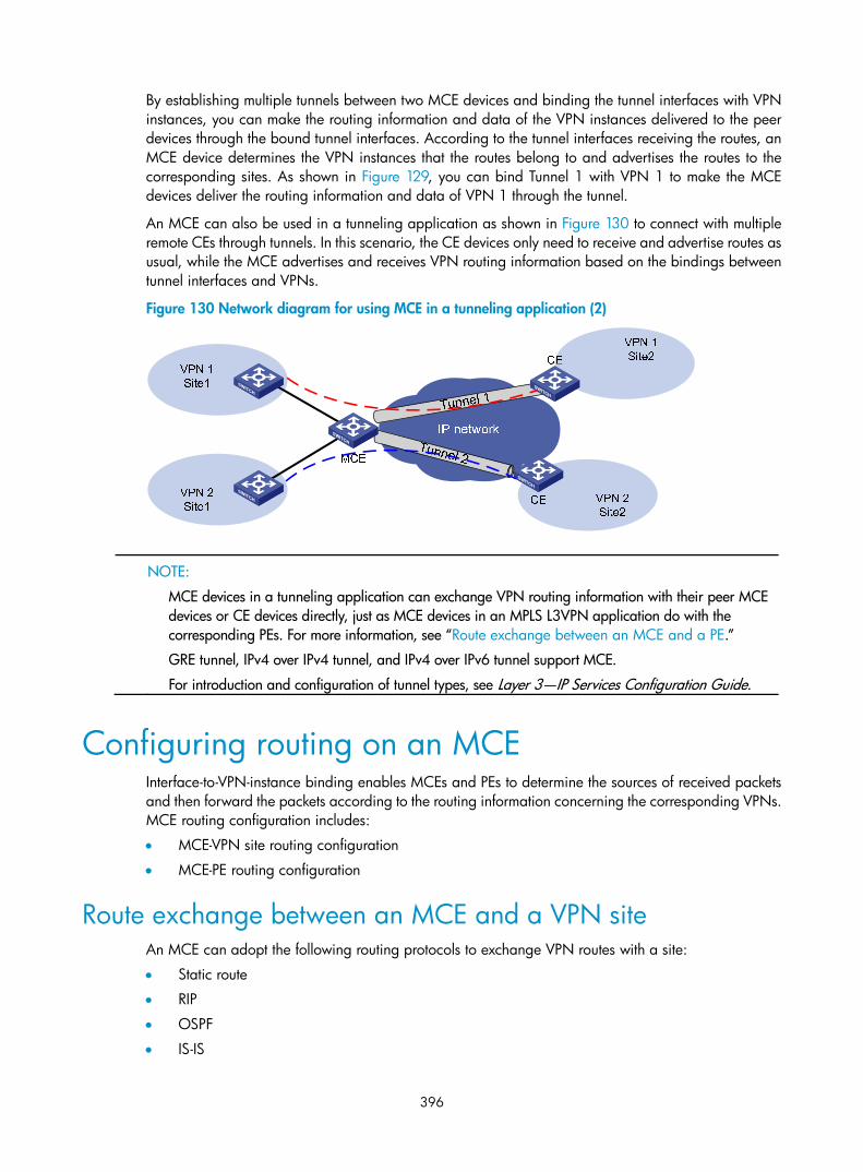
396
By establishing multiple tunnels between two MCE devices and binding the tunnel interfaces with VPN instances, you can make the routing information and data of the VPN instances delivered to the peer devices through the bound tunnel interfaces. According to the tunnel interfaces receiving the routes, an MCE device determines the VPN instances that the routes belong to and advertises the routes to the corresponding sites. As shown in Figure 129, you can bind Tunnel 1 with VPN 1 to make the MCE devices deliver the routing information and data of VPN 1 through the tunnel.
An MCE can also be used in a tunneling application as shown in Figure 130 to connect with multiple remote CEs through tunnels. In this scenario, the CE devices only need to receive and advertise routes as usual, while the MCE advertises and receives VPN routing information based on the bindings between tunnel interfaces and VPNs.
Figure 130 Network diagram for using MCE in a tunneling application (2)
NOTE:
MCE devices in a tunneling application can exchange VPN routing information with their peer MCE devices or CE devices directly, just as MCE devices in an MPLS L3VPN application do with the corresponding PEs. For more information, see “Route exchange between an MCE and a PE.”
GRE tunnel, IPv4 over IPv4 tunnel, and IPv4 over IPv6 tunnel support MCE.
For introduction and configuration of tunnel types, see Layer 3—IP Services Configuration Guide.
Configuring routing on an MCE Interface-to-VPN-instance binding enables MCEs and PEs to determine the sources of received packets and then forward the packets according to the routing information concerning the corresponding VPNs. MCE routing configuration includes:
• MCE-VPN site routing configuration
• MCE-PE routing configuration
Route exchange between an MCE and a VPN site An MCE can adopt the following routing protocols to exchange VPN routes with a site:
• Static route
• RIP
• OSPF
• IS-IS

397
• eBGP
NOTE:
This briefly introduces the cooperation of routing protocols and MCE. For information about the routing protocols, see Layer 3—IP Routing Configuration Guide.
Static routes
An MCE can communicate with a site through static routes. As static routes configured for traditional CEs take effect globally, address overlapping between multiple VPNs remains a problem until the emergence of MCE. MCE allows static-route-to-VPN-instance binding, which isolates the static routes of different VPNs.
RIP
The switch can bind RIP processes to VPN instances. With these bindings on the MCE, private network routes of different VPNs can be exchanged between MCE and sites through different RIP processes, isolating and securing VPN routes.
OSPF
The switch can bind OSPF processes to VPN instances and isolate the routes of different VPNs.
For an OSPF process bound to a VPN instance, the router ID of the public network configured in system view is invalid. You must specify the router ID when creating an OSPF process.
An OSPF process can be bound to only one VPN instance; however, a VPN instance can use multiple OSPF processes for private network route transmission. To make sure that routes can be advertised properly, configure the same domain ID for all the OSPF processes bound to the same VPN instance.
NOTE:
When an OSPF route is imported to the BGP routing table as a BGP route on a PE, some attributes of theOSPF route get lost. When the BGP route is imported to the OSPF routing table on the remote CE, not allthe attributes of the original OSPF routes can be restored. As a result, the route cannot be distinguished from the routes imported from other domains. To distinguish OSPF routes imported from different OSPF domains, the OSPF routes to be imported to the BGP routing tables on PEs must carry an attribute (the OSPF domain ID) to identify the OSPF domains. The domain ID of an OSPF process is contained in the routes generated by the process. When an OSPF route is imported to BGP, the domain ID is added to BGPVPN routes as the extended BGP community.
In cases where a VPN has multiple MCE devices attached to it and when an MCE device advertises the routes learned from BGP within the VPN, the routes may be learned by other MCE devices, generating route loops. To prevent route loops, configure route tags for different VPN instances on each MCE. HP recommends that you assign the same route tag to the same VPN on all MCEs.
IS-IS
Similar to those in OSPF, IS-IS processes can be bound to VPN instances for private network routes to be exchanged between MCE and sites. An IS-IS process can be bound to only one VPN instance.
eBGP
To use eBGP for exchanging routing information between an MCE and VPN sites, you must configure a BGP peer for each VPN instance on the MCE, and redistribute the IGP routes of each VPN instance on the VPN sites. You also can configure filtering policies to filter the received routes and the routes to be advertised.

398
Route exchange between an MCE and a PE Routing information entries are bound to specific VPN instances on an MCE device, and packets of each VPN instance are forwarded between MCE and PE according to interface. As a result, VPN routing information can be transmitted by performing relatively simple configurations between MCE and PE, such as importing the VPN routing entries on MCE devices to the routing table of the routing protocol running between MCE and PEs.
The following routing protocols can be used between MCE and PE devices for routing formation exchange:
• Static route
• RIP
• OSPF
• IS-IS
• eBGP
For information about routing protocol configuration and route import, see Layer 3—IP Routing Configuration Guide.
Configuring an MCE
Configuring VPN instances Configuring VPN instances is required in all MCE networking schemes.
By configuring VPN instances on a PE, you isolate not only VPN routes from public network routes, but also routes of a VPN from those of another VPN. This feature allows VPN instances to be used in networking scenarios besides MCE.
Creating a VPN Instance
A VPN instance is associated with a site. It is a collection of the VPN membership and routing rules of its associated site. A VPN instance does not necessarily correspond to one VPN.
A VPN instance takes effect only after you configure an RD for it. Before configuring an RD for a VPN instance, you can configure no other parameters for the instance but a description.
You can configure a description for a VPN instance to record its related information, such as its relationship with a certain VPN.
Follow these steps to create and configure a VPN instance:
To do… Use the command… Remarks Enter system view system-view —
Create a VPN instance and enter VPN instance view ip vpn-instance vpn-instance-name Required
Configure an RD for the VPN instance
route-distinguisher route-distinguisher
Required
Configure a description for the VPN instance
description text Optional

399
NOTE:
For easy management, set the same RD for the same VPN instance on the MCE and PE.
Associating a VPN instance with an interface
NOTE:
• In an MPLS L3VPN application, you must associate VPN instances with the interfaces connecting the PEs.
• In a tunneling application, you must associate VPN instances with the tunnel interfaces connecting the peer MCE devices or CE devices.
• You can add a management Ethernet interface on the switch to a VPN so that the IP address of the interface only participates in the route calculation of the specified VPN.
After creating and configuring a VPN instance, you associate the VPN instance with the interface for connecting different VPN sites.
Follow these steps to associate a VPN instance with an interface:
To do… Use the command… Remarks Enter system view system-view —
Enter interface view interface interface-type interface-number —
Associate the current interface with the VPN instance
ip binding vpn-instance vpn-instance-name
Required
No VPN instance is associated with an interface by default.
NOTE:
The ip binding vpn-instance command clears the IP address of the interface on which it is configured. Besure to reconfigure an IP address for the interface after configuring the command.
Configuring route-related attributes of a VPN instance
The control process of VPN route advertisement is as follows:
• When a VPN route learned from a site gets redistributed into BGP, BGP associates it with a VPN target extended community attribute list, which is usually the export target attribute of the VPN instance associated with the site.
• The VPN instance determines which routes it can accept and redistribute according to the import-extcommunity in the VPN target.
• The VPN instance determines how to change the VPN targets attributes for routes to be advertised according to the export-extcommunity in the VPN target.
Follow these steps to configure route related attributes of a VPN instance:
To do… Use the command… Remarks Enter system view system-view —
Enter VPN instance view ip vpn-instance vpn-instance-name Required
Enter IPv4 VPN view ipv4-family Optional
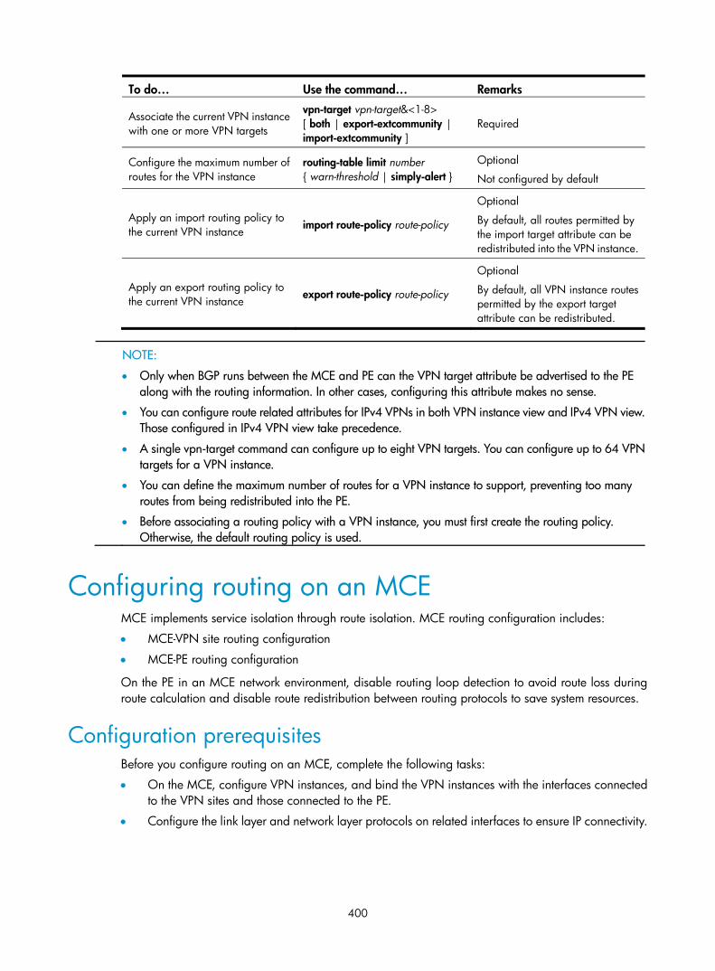
400
To do… Use the command… Remarks
Associate the current VPN instance with one or more VPN targets
vpn-target vpn-target&<1-8> [ both | export-extcommunity | import-extcommunity ]
Required
Configure the maximum number of routes for the VPN instance
routing-table limit number { warn-threshold | simply-alert }
Optional
Not configured by default
Apply an import routing policy to the current VPN instance
import route-policy route-policy
Optional
By default, all routes permitted by the import target attribute can be redistributed into the VPN instance.
Apply an export routing policy to the current VPN instance
export route-policy route-policy
Optional
By default, all VPN instance routes permitted by the export target attribute can be redistributed.
NOTE:
• Only when BGP runs between the MCE and PE can the VPN target attribute be advertised to the PE along with the routing information. In other cases, configuring this attribute makes no sense.
• You can configure route related attributes for IPv4 VPNs in both VPN instance view and IPv4 VPN view.Those configured in IPv4 VPN view take precedence.
• A single vpn-target command can configure up to eight VPN targets. You can configure up to 64 VPNtargets for a VPN instance.
• You can define the maximum number of routes for a VPN instance to support, preventing too many routes from being redistributed into the PE.
• Before associating a routing policy with a VPN instance, you must first create the routing policy. Otherwise, the default routing policy is used.
Configuring routing on an MCE MCE implements service isolation through route isolation. MCE routing configuration includes:
• MCE-VPN site routing configuration
• MCE-PE routing configuration
On the PE in an MCE network environment, disable routing loop detection to avoid route loss during route calculation and disable route redistribution between routing protocols to save system resources.
Configuration prerequisites Before you configure routing on an MCE, complete the following tasks:
• On the MCE, configure VPN instances, and bind the VPN instances with the interfaces connected to the VPN sites and those connected to the PE.
• Configure the link layer and network layer protocols on related interfaces to ensure IP connectivity.

401
Configuring routing between MCE and VPN site Configuring static routing between MCE and VPN site
An MCE can reach a VPN site through a static route. Static routing on a traditional CE is globally effective and thus does not support address overlapping among VPNs. An MCE supports binding a static route with a VPN instance, so that the static routes of different VPN instances can be isolated from each other.
Follow these steps to configure static routing between MCE and VPN site:
To do… Use the command… Remarks Enter system view system-view —
Configure static routes for a VPN instance
ip route-static dest-address { mask | mask-length } { gateway-address | interface-type interface-number [ gateway-address ] | vpn-instance d-vpn-instance-name gateway-address } [ preference preference-value ] [ tag tag-value ] [ description description-text ]
Required
Use either command.
Perform this configuration on the MCE. On a VPN site, configure a normal static route.
ip route-static vpn-instance s-vpn-instance-name&<1-6> dest-address { mask | mask-length } { gateway-address [ public ] | interface-type interface-number [ gateway-address ] | vpn-instance d-vpn-instance-name gateway-address } [ preference preference-value ] [ tag tag-value ] [ description description-text ]
Configure the default precedence for static routes
ip route-static default-preference default-preference-value
Optional
60 by default
Configuring RIP between MCE and VPN site
A RIP process belongs to the public network or a single VPN instance. If you create a RIP process without binding it to a VPN instance, the process belongs to the public network. By configuring RIP process-to-VPN instance bindings on a IPv6 MCE, you allow routes of different VPNs to be exchanged between the MCE and the sites through different RIP processes, ensuring the separation and security of VPN routes.
Follow these steps to configure RIP between MCE and VPN site:
To do… Use the command… Remarks Enter system view system-view —
Create a RIP process for a VPN instance and enter RIP view
rip [ process-id ] vpn-instance vpn-instance-name
Required
Perform this configuration on the MCE. On a VPN site, create a normal RIP process.
Enable RIP on the interface attached to the specified network network network-address
Required
By default, RIP is disabled on an interface.
Redistribute remote site routes advertised by the PE
import-route protocol [ process-id ] [ allow-ibgp ] [ cost cost | route-policy route-policy-name | tag tag ] *
Required
By default, no route is redistributed into RIP.

402
To do… Use the command… Remarks
Configure the default cost value for the redistributed routes default cost value
Optional
0 by default
NOTE:
For more information about RIP, see Layer 3—IP Routing Configuration Guide.
Configuring OSPF between MCE and VPN site
An OSPF process belongs to the public network or a single VPN instance. If you create an OSPF process without binding it to a VPN instance, the process belongs to the public network.
By configuring OSPF process-to-VPN instance bindings on a MCE, you allow routes of different VPNs to be exchanged between the MCE and the sites through different OSPF processes, ensuring the separation and security of VPN routes.
Follow these steps to configure OSPF between MCE and VPN site:
To do… Use the command… Remarks Enter system view system-view —
Create an OSPF process for a VPN instance and enter OSPF view
ospf [ process-id | router-id router-id | vpn-instance vpn-instance-name ] *
Required
Perform this configuration on the MCE. On a VPN site, create a normal OSPF process.
Configure the OSPF domain ID domain-id domain-id [ secondary ]
Optional
0 by default.
Perform this configuration on the MCE. On a VPN site, perform the common OSPF configuration.
Redistribute remote site routes advertised by the PE
import-route protocol [ process-id | allow-ibgp ] [ cost cost | type type | tag tag | route-policy route-policy-name ] *
Required
By default, no route of any other routing protocol is redistributed into OSPF.
Create an OSPF area and enter OSPF area view
area area-id Required
By default, no OSPF area is created.
Enable OSPF on the interface attached to the specified network in the area
network ip-address wildcard-mask
Required
By default, an interface neither belongs to any area nor runs OSPF.

403
NOTE:
• An OSPF process that is bound with a VPN instance does not use the public network router ID configured in system view. Therefore, you must configure a router ID when starting the OSPF process. AllOSPF processes for the same VPN must be configured with the same OSPF domain ID to ensure correctroute advertisement.
• An OSPF process can belong to only one VPN instance, but one VPN instance can use multiple OSPFprocesses to advertise the VPN routes.
• For more information about OSPF, see Layer 3—IP Routing Configuration Guide.
Configuring IS-IS between MCE and VPN site
An IS-IS process belongs to the public network or a single VPN instance. If you create an IS-IS process without binding it to a VPN instance, the process belongs to the public network.
By configuring IS-IS process-to-VPN instance bindings on a MCE, you allow routes of different VPNs to be exchanged between the MCE and the sites through different IS-IS processes, ensuring the separation and security of VPN routes.
Follow these steps to configure IS-IS between MCE and VPN site:
To do… Use the command… Remarks Enter system view system-view —
Create an IS-IS process for a VPN instance and enter IS-IS view
isis [ process-id ] vpn-instance vpn-instance-name
Required
Perform this configuration on the MCE. On a VPN site, configure a normal IS-IS process.
Configure a network entity title network-entity net Required
Not configured by default.
Redistribute remote site routes advertised by the PE
import-route { isis [ process-id ] | ospf [ process-id ] | rip [ process-id ] | bgp [ allow-ibgp ] | direct | static } [ cost cost | cost-type { external | internal } | [ level-1 | level-1-2 | level-2 ] | route-policy route-policy-name | tag tag ] *
Optional
By default, IS-IS does not redistribute routes of any other routing protocol.
If you do not specify the route level in the command, the command will redistribute routes to the level-2 routing table by default.
Return to system view quit —
Enter interface view interface interface-type interface-number
—
Enable the IS-IS process on the interface isis enable [ process-id ]
Required
Disabled by default.
NOTE:
For more information about IS-IS, see Layer 3—IP Routing Configuration Guide.

404
Configuring eBGP between MCE and VPN site
To use eBGP for exchanging routing information between an MCE and VPN sites, you must configure a BGP peer for each VPN instance on the MCE, and redistribute the IGP routes of each VPN instance on the VPN sites.
If eBGP is used for route exchange, you also can configure filtering policies to filter the received routes and the routes to be advertised.
1. Configure the MCE
Follow these steps to configure the MCE:
To do… Use the command… Remarks Enter system view system-view —
Enter BGP view bgp as-number —
Enter BGP-VPN instance view ipv4-family vpn-instance vpn-instance-name
Required
Configure an eBGP peer peer { group-name | ip-address } [ as-number as-number ]
Required
Use either command
Allow routing loops—allow the local AS number to appear in the AS_PATH attribute of a received route, and you can also configure the maximum number of times that such case is allowed to appear
peer { group-name | ip-address } allow-as-loop [ number ]
Redistribute remote site routes advertised by the PE
import-route protocol [ process-id | all-processes ] [ med med-value | route-policy route-policy-name ] *
Required
By default, no route redistribution is configured.
Configure a filtering policy to filter the routes to be advertised
filter-policy { acl-number | ip-prefix ip-prefix-name } export [ direct | isis process-id | ospf process-id | rip process-id | static ]
Optional
By default, BGP does not filter the routes to be advertised.
Configure a filtering policy to filter the received routes
filter-policy { acl-number | ip-prefix ip-prefix-name } import
Optional
By default, BGP does not filter the received routes.
Normally, BGP checks routing loops by examining AS numbers. If eBGP is used between the MCE and a site, when the MCE advertises its routing information with its AS number to the site and then receives routing update information from the site, the route update message carries the AS number of the MCE, making the MCE unable to receive this route update message. In this case, to enable the MCE to receive route updates normally, configure the MCE to allow routing loops.
In standard BGP/OSPF route redistribution, when a route is redistributed into OSPF from BGP on the MCE, the route’s original OSPF attribute cannot be restored, making the route unable to be distinguished from routes redistributed from other domains. To distinguish routes of different OSPF domains, you must enable a route to carry the OSPF domain ID when the route is redistributed from OSPF into BGP on the peer PE. Thus, the domain ID of an OSPF process is carried in a route generated by the process. When the OSPF route is redistributed into BGP, the domain ID is added to the BGP VPN route and is transmitted over the network as the extended community attribute of BGP.

405
After you configure a BGP VPN instance, the BGP route exchange for the VPN instance is the same with the normal BGP VPN route exchange. For more information about BGP, see Layer 3—IP Routing Configuration Guide.
2. Configure a VPN site
Follow these steps to configure a VPN site:
To do… Use the command… Remarks Enter system view system-view —
Enter BGP view bgp as-number —
Configure the MCE as the eBGP peer
peer { group-name | ip-address } [ as-number as-number ] Required
Redistribute the IGP routes of the VPN
import-route protocol [ process-id ] [ med med-value | route-policy route-policy-name ] *
Optional
A VPN site must advertise the VPN network addresses it can reach to the connected MCE.
Configuring routing between MCE and PE MCE-PE routing configuration includes these tasks:
• Bind the MCE-PE interfaces to VPN instances
• Perform route configurations
• Redistribute VPN routes into the routing protocol running between the MCE and the PE.
Configuring static routing between MCE and PE
Follow these steps to configure static routing between MCE and PE:
To do… Use the command… Remarks Enter system view system-view —
Configure static routes for a VPN instance
ip route-static dest-address { mask | mask-length } { gateway-address | interface-type interface-number [ gateway-address ] | vpn-instance d-vpn-instance-name gateway-address } [ preference preference-value ] [ tag tag-value ] [ description description-text ] Required
Use either command. ip route-static vpn-instance s-vpn-instance-name&<1-6>
dest-address { mask | mask-length } { gateway-address [ public ] | interface-type interface-number [ gateway-address ] | vpn-instance d-vpn-instance-name gateway-address } [ preference preference-value ] [ tag tag-value ] [ description description-text ]
Configure the default precedence for static routes
ip route-static default-preference default-preference-value Optional
60 by default
Configuring RIP between MCE and PE
Follow these steps to configure RIP between MCE and PE:
To do… Use the command… Remarks Enter system view system-view —

406
To do… Use the command… Remarks Create a RIP process for a VPN instance and enter RIP view
rip [ process-id ] vpn-instance vpn-instance-name Required
Enable RIP on the interface attached to the specified network
network network-address Required
By default, RIP is disabled on an interface.
Redistribute the VPN routes import-route protocol [ process-id ] [ allow-ibgp ] [ cost cost | route-policy route-policy-name | tag tag ] *
Required
By default, no route of any other routing protocol is redistributed into RIP.
Configure the default cost value for the redistributed routes
default cost value Optional
0 by default
NOTE:
For more information about RIP, see Layer 3—IP Routing Configuration Guide.
Configuring OSPF between MCE and PE
Follow these steps to configure OSPF between MCE and PE:
To do… Use the command… Remarks Enter system view system-view —
Create an OSPF process for a VPN instance and enter OSPF view
ospf [ process-id | router-id router-id | vpn-instance vpn-instance-name ] *
Required
Disable routing loop detection vpn-instance-capability simple
Required
Disabled by default
You must disable routing loop detection for a VPN OSPF process on the MCE. Otherwise, the MCE cannot receive OSPF routes from the PE.
Configure the OSPF domain ID domain-id domain-id [ secondary ]
Optional
0 by default
Redistribute the VPN routes
import-route protocol [ process-id | allow-ibgp ] [ cost cost | type type | tag tag | route-policy route-policy-name ] *
Required
By default, no route of any other routing protocol is redistributed into OSPF.
Configure a filtering policy to filter the redistributed routes
filter-policy { acl-number | ip-prefix ip-prefix-name } export [ protocol [ process-id ] ]
Optional
By default, redistributed routes are not filtered.
Configure the default parameters for redistributed routes (cost, route number, tag, and type)
default { cost cost | limit limit | tag tag | type type } *
Optional
The default cost is 1, the default maximum number of routes redistributed per time is 1000, the default tag is 1, and default type of redistributed routes is Type-2.

407
To do… Use the command… Remarks Create an OSPF area and enter OSPF area view
area area-id Required
By default, no OSPF area is created.
Enable OSPF on the interface attached to the specified network in the area
network ip-address wildcard-mask Required
By default, an interface neither belongs to any area nor runs OSPF.
NOTE:
For more information about OSPF, see Layer 3—IP Routing Configuration Guide.
Configuring IS-IS between MCE and PE
Follow these steps to configure IS-IS between MCE and PE:
To do… Use the command… Remarks Enter system view system-view —
Create an IS-IS process for a VPN instance and enter IS-IS view
isis [ process-id ] vpn-instance vpn-instance-name Required
Configure a network entity title network-entity net
Required
Not configured by default.
Redistribute the VPN routes
import-route { isis [ process-id ] | ospf [ process-id ] | rip [ process-id ] | bgp [ allow-ibgp ] | direct | static } [ cost cost | cost-type { external | internal } | [ level-1 | level-1-2 | level-2 ] | route-policy route-policy-name | tag tag ] *
Optional
By default, IS-IS does not redistribute routes of any other routing protocol.
If you do not specify the route level in the command, the command will redistribute routes to the level-2 routing table by default.
Configure a filtering policy to filter the redistributed routes
filter-policy { acl-number | ip-prefix ip-prefix-name | route-policy route-policy-name } export [ isis process-id | ospf process-id | rip process-id | bgp | direct | static ]
Optional
By default, IS-IS does not filter redistributed routes.
Return to system view quit —
Enter interface view interface interface-type interface-number —
Enable the IS-IS process on the interface isis enable [ process-id ]
Required
Disabled by default.
NOTE:
For more information about IS-IS, see Layer 3—IP Routing Configuration Guide.
Configuring eBGP between MCE and PE
Follow these steps to configure eBGP between MCE and PE:

408
To do… Use the command… Remarks Enter system view system-view —
Enter BGP view bgp as-number —
Enter BGP-VPN instance view ipv4-family vpn-instance vpn-instance-name Required
Configure the PE as the eBGP peer
peer { group-name | ip-address } [ as-number as-number ] Required
Redistribute the VPN routes of the VPN site
import-route protocol [ process-id | all-processes ] [ med med-value | route-policy route-policy-name ] *
Required
By default, No route redistribution is configured.
Configure a filtering policy to filter the routes to be advertised
filter-policy { acl-number | ip-prefix ip-prefix-name } export [ direct | isis process-id | ospf process-id | rip process-id | static ]
Optional
By default, BGP does not filter the routes to be advertised.
Configure a filtering policy to filter the received routes
filter-policy { acl-number | ip-prefix ip-prefix-name } import
Optional
By default, BGP does not filter the received routes.
NOTE:
BGP runs within a VPN in the same way as it runs within a public network. For more information about BGP, see Layer 3—IP Routing Configuration Guide.
Displaying and maintaining MCE
Resetting BGP connections When BGP configuration changes, you can use the soft reset function or reset BGP connections to make new configurations take effect. Soft reset requires that BGP peers have route refreshment capability (supporting Route-Refresh messages).
To do… Use the command… Remarks
Soft reset the BGP connections in a specified VPN instance
refresh bgp vpn-instance vpn-instance-name { ip-address | all | external | group group-name } { export | import }
Available in user view
Reset BGP connections of a VPN instance
reset bgp vpn-instance vpn-instance-name { as-number | ip-address | all | external | group group-name }
Available in user view

409
Displaying and maintaining MCE To do… Use the command… Remarks
Display information about the routing table associated with a VPN instance
display ip routing-table vpn-instance vpn-instance-name [ verbose ] [ verbose ] [ | { begin | exclude | include } regular-expression ]
Available in any view
Display information about a specific VPN instance or all VPN instances
display ip vpn-instance [ instance-name vpn-instance-name ] [ | { begin | exclude | include } regular-expression ]
Available in any view
Display information about the FIB of a VPN instance
display fib vpn-instance vpn-instance-name [ acl acl-number | ip-prefix ip-prefix-name ] [ | { begin | exclude | include } regular-expression ]
Available in any view
Display information about the FIB of a VPN instance that matches the specified destination IP address
display fib vpn-instance vpn-instance-name ip-address [ mask | mask-length ] [ | { begin | exclude | include } regular-expression ]
Available in any view
Display information about a specific peer group or all BGP VPNv4 peer groups
display bgp vpnv4 vpn-instance vpn-instance-name group [ group-name ] [ | { begin | exclude | include } regular-expression ]
Available in any view
Display information about BGP VPNv4 routes injected into a specific VPN instance or all VPN instances
display bgp vpnv4 vpn-instance vpn-instance-name network [ | { begin | exclude | include } regular-expression ]
Available in any view
Display BGP VPNv4 AS path information
display bgp vpnv4 vpn-instance vpn-instance-name paths [ as-regular-expression | { | { begin | exclude | include } regular-expression } ]
Available in any view
Display information about BGP VPNv4 peers
display bgp vpnv4 vpn-instance vpn-instance-name peer [ group-name log-info | ip-address { log-info | verbose } | verbose ] [ | { begin | exclude | include } regular-expression ]
Available in any view

410
To do… Use the command… Remarks
Display the BGP VPNv4 routing information of a specified VPN instance
display bgp vpnv4 vpn-instance vpn-instance-name routing-table [ [ network-address [ { mask | mask-length } [ longer-prefixes ] ] | as-path-acl as-path-acl-number | cidr | community [ aa:nn ]&<1-13> [ no-advertise | no-export | no-export-subconfed ] * [ whole-match ] | community-list { basic-community-list-number [ whole-match ] | adv-community-list-number }&<1-16> | dampened | dampening parameter | different-origin-as | flap-info [ network-address [ { mask | mask-length } [ longer-match ] ] | as-path-acl as-path-acl-number ] | peer ip-address { advertised-routes | received-routes } | statistic ] [ | { begin | exclude | include } regular-expression ] | [ flap-info ] regular-expression as-regular-expression ]
Available in any view
Clear the route flap dampening information of a VPN instance
reset bgp vpn-instance vpn-instance-name dampening [ network-address [ mask | mask-length ]
Available in user view
Clear route flap history information about a BGP peer of a VPN instance
reset bgp vpn-instance vpn-instance-name ip-address flap-info
reset bgp vpn-instance vpn-instance-name flap-info [ ip-address [ mask | mask-length ] | as-path-acl as-path-acl-number | regexp as-path-regexp ]
Available in user view
NOTE:
For commands to display information about a routing table, see Layer 3—IP Routing Command Reference.
MCE configuration examples
Using OSPF to advertise VPN routes to the PE Network requirements
As shown in Figure 131, the MCE device is connected to VPN 1 through VLAN-interface 10 and to VPN 2 through VLAN-interface 20. RIP runs in VPN 2.
Configure the MCE device to separate routes from different VPNs and advertise the VPN routes to PE 1 through OSPF.

411
Figure 131 Network diagram
Configuration procedure
Assume that the system name of the MCE device is MCE, the system names of the edge devices of VPN 1 and VPN 2 are VR1 and VR2 respectively, and the system name of PE 1 is PE1.
1. Configure the VPN instances on the MCE and PE 1.
# On the MCE, configure VPN instances vpn1 and vpn2, and specify an RD and VPN targets for each VPN instance. <MCE> system-view
[MCE] ip vpn-instance vpn1
[MCE-vpn-instance-vpn1] route-distinguisher 10:1
[MCE-vpn-instance-vpn1] vpn-target 10:1
[MCE-vpn-instance-vpn1] quit
[MCE] ip vpn-instance vpn2
[MCE-vpn-instance-vpn2] route-distinguisher 20:1
[MCE-vpn-instance-vpn2] vpn-target 20:1
[MCE-vpn-instance-vpn2] quit
# Create VLAN 10, add port Ethernet 1/0/1 to VLAN 10, and create VLAN-interface 10. [MCE] vlan 10
[MCE-vlan10] port ethernet 1/0/1
[MCE-vlan10] quit
[MCE] interface vlan-interface 10
# Bind VLAN-interface 10 with VPN instance vpn1, and configure an IP address for VLAN-interface 10. [MCE-Vlan-interface10] ip binding vpn-instance vpn1

412
[MCE-Vlan-interface10] ip address 10.214.10.3 24
# Configure VLAN 20, add port Ethernet 1/0/2 to VLAN 20, bind VLAN-interface 20 with VPN instance vpn2, and specify an IP address for VLAN-interface 20. [MCE-Vlan-interface10] quit
[MCE] vlan 20
[MCE-vlan20] port ethernet 1/0/2
[MCE-vlan20] quit
[MCE] interface vlan-interface 20
[MCE-Vlan-interface20] ip binding vpn-instance vpn2
[MCE-Vlan-interface20] ip address 10.214.20.3 24
[MCE-Vlan-interface20] quit
# On PE 1, configure VPN instances vpn1 and vpn2, specify an RD and VPN targets for each VPN instance. <PE1> system-view
[PE1] ip vpn-instance vpn1
[PE1-vpn-instance-vpn1] route-distinguisher 30:1
[PE1-vpn-instance-vpn1] vpn-target 10:1
[PE1-vpn-instance-vpn1] quit
[PE1] ip vpn-instance vpn2
[PE1-vpn-instance-vpn2] route-distinguisher 40:1
[PE1-vpn-instance-vpn2] vpn-target 20:1
[PE1-vpn-instance-vpn2] quit
2. Configure routing between the MCE and VPN sites.
The MCE is connected to VPN 1 directly, and no routing protocol is enabled in VPN 1. Therefore, you can configure static routes.
# On VR 1, assign IP address 10.214.10.2/24 to the interface connected to MCE and 192.168.0.1/24 to the interface connected to VPN 1. Add ports to VLANs correctly. (Details not shown)
# On VR 1, configure a default route with the next hop as 10.214.10.3. <VR1> system-view
[VR1] ip route-static 0.0.0.0 0.0.0.0 10.214.10.3
# On the MCE, configure a static route to 192.168.0.0/24, specify the next hop as 10.214.10.2, and bind the static route with VPN instance vpn1. [MCE] ip route-static vpn-instance vpn1 192.168.0.0 24 10.214.10.2
# On the MCE, display the routing information maintained for VPN instance vpn1. [MCE] display ip routing-table vpn-instance vpn1
Routing Tables: vpn1
Destinations : 5 Routes : 5
Destination/Mask Proto Pre Cost NextHop Interface
10.214.10.0/24 Direct 0 0 10.214.10.3 Vlan10
10.214.10.3/32 Direct 0 0 127.0.0.1 InLoop0
127.0.0.0/8 Direct 0 0 127.0.0.1 InLoop0
127.0.0.1/32 Direct 0 0 127.0.0.1 InLoop0
192.168.0.0/24 Static 60 0 10.214.10.2 Vlan10
The output shows that the MCE has a static route for VPN instance vpn1.

413
# Run RIP in VPN 2. Create RIP process 20 and bind it with VPN instance vpn2 on the MCE, so that the MCE can learn the routes of VPN 2 and add them to the routing table of the VPN instance vpn2. [MCE] rip 20 vpn-instance vpn2
# Advertise subnet 10.214.20.0. [MCE-rip-20] network 10.214.20.0
[MCE-rip-20] quit
# On VR 2, assign IP address 10.214.20.2/24 to the interface connected to MCE and 192.168.10.1/24 to the interface connected to VPN 2. (Details not shown)
# Configure RIP, and advertise subnets 192.168.10.0 and 10.214.20.0. <VR2> system-view
[VR2] rip 20
[VR2-rip-20] network 192.168.10.0
[VR2-rip-20] network 10.214.20.0
# On the MCE, display the routing information maintained for VPN instance vpn2. [MCE] display ip routing-table vpn-instance vpn2
Routing Tables: vpn2
Destinations : 5 Routes : 5
Destination/Mask Proto Pre Cost NextHop Interface
10.214.20.0/24 Direct 0 0 10.214.20.3 Vlan20
10.214.20.3/32 Direct 0 0 127.0.0.1 InLoop0
127.0.0.0/8 Direct 0 0 127.0.0.1 InLoop0
127.0.0.1/32 Direct 0 0 127.0.0.1 InLoop0
192.168.10.0/24 RIP 100 1 10.214.20.2 Vlan20
The output shows that the MCE has learned the private routes of VPN 2. The MCE maintains the routes of VPN 1 and those of VPN2 in two different routing tables. In this way, routes from different VPNs are separated.
3. Configure routing between MCE and PE 1.
# The MCE uses port Ethernet 1/0/3 to connect to PE’s port Ethernet 1/0/1. Configure the two ports as trunk ports, and configure them to permit packets carrying VLAN tags 30 and 40 to pass. [MCE] interface ethernet 1/0/3
[MCE-Ethernet1/0/3] port link-type trunk
[MCE-Ethernet1/0/3] port trunk permit vlan 30 40
[MCE-Ethernet1/0/3] quit
# Configure port Ethernet1/0/1 on the PE. [PE1] interface ethernet 1/0/1
[PE1-Ethernet1/0/1] port link-type trunk
[PE1-Ethernet1/0/1] port trunk permit vlan 30 40
[PE1-Ethernet1/0/1] quit
# On the MCE, create VLAN 30 and VLAN-interface 30, bind the VLAN interface with VPN instance vpn1, and configure an IP address for the VLAN interface. [MCE] vlan 30
[MCE-vlan30] quit
[MCE] interface vlan-interface 30
[MCE-Vlan-interface30] ip binding vpn-instance vpn1

414
[MCE-Vlan-interface30] ip address 30.1.1.1 24
[MCE-Vlan-interface30] quit
# On the MCE, create VLAN 40 and VLAN-interface 40, bind the VLAN interface with VPN instance vpn2, and configure an IP address for the VLAN interface. [MCE] vlan 40
[MCE-vlan40] quit
[MCE] interface vlan-interface 40
[MCE-Vlan-interface40] ip binding vpn-instance vpn2
[MCE-Vlan-interface40] ip address 40.1.1.1 24
[MCE-Vlan-interface40] quit
# On PE 1, create VLAN 30 and VLAN-interface 30, bind the VLAN interface with VPN instance vpn1, and configure an IP address for the VLAN interface. [PE1] vlan 30
[PE1-vlan30] quit
[PE1] interface vlan-interface 30
[PE1-Vlan-interface30] ip binding vpn-instance vpn1
[PE1-Vlan-interface30] ip address 30.1.1.2 24
[PE1-Vlan-interface30] quit
# On PE 1, create VLAN 40 and VLAN-interface 40, bind the VLAN interface with VPN instance vpn2, and configure an IP address for the VLAN interface. [PE1] vlan 40
[PE1-vlan40] quit
[PE1] interface vlan-interface 40
[PE1-Vlan-interface40] ip binding vpn-instance vpn2
[PE1-Vlan-interface40] ip address 40.1.1.2 24
[PE1-Vlan-interface40] quit
# Configure the IP address of the interface Loopback0 as 101.101.10.1 for the MCE and as 100.100.10.1 for PE 1. Specify the loopback interface address as the router ID for the MCE and PE 1. (Details not shown)
# Enable OSPF process 10 on the MCE, bind the process to VPN instance vpn1, and set the domain ID to 10. [MCE] ospf 10 router-id 101.101.10.1 vpn-instance vpn1
[MCE-ospf-10] vpn-instance-capability simple
[MCE-ospf-10] domain-id 10
# On the MCE, advertise subnet 30.1.1.0 in area 0, and redistribute the static route of VPN 1. [MCE-ospf-10] area 0
[MCE-ospf-10-area-0.0.0.0] network 30.1.1.0 0.0.0.255
[MCE-ospf-10-area-0.0.0.0] quit
[MCE-ospf-10] import-route static
# On PE 1, start OSPF process 10, bind the process with VPN instance vpn1, set the domain ID to 10, and advertise subnet 30.1.1.0 in area 0. [PE1] ospf 10 router-id 100.100.10.1 vpn-instance vpn1
[PE1-ospf-10] domain-id 10
[PE1-ospf-10] area 0
[PE1-ospf-10-area-0.0.0.0] network 30.1.1.0 0.0.0.255
[PE1-ospf-10-area-0.0.0.0] quit

415
[PE1-ospf-10] quit
# On PE 1, display the routing table of VPN1. [PE1] display ip routing-table vpn-instance vpn1
Routing Tables: vpn1
Destinations : 5 Routes : 5
Destination/Mask Proto Pre Cost NextHop Interface
30.1.1.0/24 Direct 0 0 30.1.1.2 Vlan30
30.1.1.2/32 Direct 0 0 127.0.0.1 InLoop0
127.0.0.0/8 Direct 0 0 127.0.0.1 InLoop0
127.0.0.1/32 Direct 0 0 127.0.0.1 InLoop0
192.168.0.0/24 O_ASE 150 1 30.1.1.1 Vlan30
The output shows that the static route of VPN 1 has been redistributed to the OSPF routing table of PE 1.
Take similar procedures to configure OSPF process 20 between MCE and PE 1 and redistribute VPN 2’s routing information from RIP into the OSPF routing table of MCE. The following output shows that PE 1 has learned the private route of VPN 2 through OSPF. <PE1> display ip routing-table vpn-instance vpn2
Routing Tables: vpn2
Destinations : 5 Routes : 5
Destination/Mask Proto Pre Cost NextHop Interface
40.1.1.0/24 Direct 0 0 40.1.1.2 Vlan40
40.1.1.2/32 Direct 0 0 127.0.0.1 InLoop0
127.0.0.0/8 Direct 0 0 127.0.0.1 InLoop0
127.0.0.1/32 Direct 0 0 127.0.0.1 InLoop0
192.168.10.0/24 O_ASE 150 1 40.1.1.1 Vlan40
Now, the routing information of the two VPNs has been redistributed into the routing tables on PE 1.
Using BGP to advertise VPN routes to the PE Network requirements
As shown in Figure 132, use an Ethernet switch as the MCE device. Advertise the VPN routes in site 1 and site 2 to PE 1, so that a VPN’s sites across the MPLS backbone network can communicate with each other normally.
Use OSPF in both site 1 and site 2. Use eBGP between the MCE and PE 1.

416
Figure 132 Network diagram
Configuration procedure
1. Configure VPN instances.
# Create VPN instances on the MCE and PE 1, and bind the VPN instances with VLAN interfaces. For the configuration procedure, see “Using OSPF to advertise VPN routes to the PE.”
2. Configure routing between the MCE and VPN sites.
# Start an OSPF process on the devices in the two VPNs and advertise the subnets. (Details not shown)
# Configure OSPF on the MCE, and bind OSPF process 10 with VPN instance vpn1 to learn the routes of VPN 1. <MCE> system-view
[MCE] ospf router-id 10.214.10.3 10 vpn-instance vpn1
[MCE-ospf-10] area 0
[MCE-ospf-10-area-0.0.0.0] network 10.214.10.0 0.0.0.255
# Display the routing table of VPN 1 on the MCE. [MCE-ospf-10-area-0.0.0.0] display ip routing-table vpn-instance vpn1
Routing Tables: vpn1
Destinations : 5 Routes : 5
Destination/Mask Proto Pre Cost NextHop Interface
10.214.10.0/24 Direct 0 0 10.214.10.3 Vlan10
10.214.10.3/32 Direct 0 0 127.0.0.1 InLoop0
127.0.0.0/8 Direct 0 0 127.0.0.1 InLoop0

417
127.0.0.1/32 Direct 0 0 127.0.0.1 InLoop0
192.168.0.0/24 OSPF 10 1 10.214.10.2 Vlan10
The output shows that the MCE has learned the private route of VPN 1 through OSPF process 10.
# On MCE, bind OSPF process 20 with VPN instance vpn2 to learn the routes of VPN 2. The configuration procedure is similar to that for OSPF process 10.
The following output shows that the MCE has learned the private route of VPN 2 through OSPF: [MCE] display ip routing-table vpn-instance vpn2
Routing Tables: vpn2
Destinations : 5 Routes : 5
Destination/Mask Proto Pre Cost NextHop Interface
10.214.20.0/24 Direct 0 0 10.214.20.3 Vlan20
10.214.20.3/32 Direct 0 0 127.0.0.1 InLoop0
127.0.0.0/8 Direct 0 0 127.0.0.1 InLoop0
127.0.0.1/32 Direct 0 0 127.0.0.1 InLoop0
192.168.0.0/24 OSPF 10 1 10.214.20.2 Vlan20
3. Configure routing between the MCE and PE 1.
# Configure the connecting ports between the MCE and PE 1 as trunk ports. The configuration procedure is similar to that described in “Using OSPF to advertise VPN routes to the PE.” (Details not shown)
# Start BGP process 100 on the MCE, and enter the IPv4 address family view of VPN instance vpn1. [MCE] bgp 100
[MCE-bgp] ipv4-family vpn-instance vpn1
# Specify PE 1 as the eBGP peer of the MCE, and redistribute the routing information of OSPF process 10. (The IP address of PE 1’s interface bound with VPN instance vpn1 is 10.100.10.3, and the BGP process is 200.) [MCE-bgp-vpn1] peer 30.1.1.2 as-number 200
[MCE-BGP-vpn1] import-route ospf 10
# On PE 1, configure BGP process 200 and specify the MCE as its eBGP peer. <PE1> system-view
[PE1] bgp 200
[PE1-bgp] ipv4-family vpn-instance vpn1
[PE1-bgp-vpn1] peer 30.1.1.1 as-number 100
[PE1-bgp-vpn1] quit
[PE1-bgp] quit
# On PE 1, display the routing information of VPN instance vpn1. [PE1] display ip routing-table vpn-instance vpn1
Routing Tables: vpn1
Destinations : 5 Routes : 5
Destination/Mask Proto Pre Cost NextHop Interface
30.1.1.0/24 Direct 0 0 30.1.1.2 Vlan30
30.1.1.2/32 Direct 0 0 127.0.0.1 InLoop0
127.0.0.0/8 Direct 0 0 127.0.0.1 InLoop0
127.0.0.1/32 Direct 0 0 127.0.0.1 InLoop0

418
192.168.0.0/24 BGP 255 2 30.1.1.1 Vlan30
# Perform similar configuration on the MCE and PE 1 for VPN 2. Redistribute the OSPF routes of VPN instance vpn2 into the eBGP routing table. (Details not shown)
The following output shows that PE 1 has learned the private route of VPN 2 through BGP: [PE1] display ip routing-table vpn-instance vpn2
Routing Tables: vpn2
Destinations : 5 Routes : 5
Destination/Mask Proto Pre Cost NextHop Interface
40.1.1.0/24 Direct 0 0 40.1.1.2 Vlan40
40.1.1.2/32 Direct 0 0 127.0.0.1 InLoop0
127.0.0.0/8 Direct 0 0 127.0.0.1 InLoop0
127.0.0.1/32 Direct 0 0 127.0.0.1 InLoop0
192.168.10.0/24 BGP 255 2 40.1.1.1 Vlan40
Now, the MCE has redistributed the OSPF routes of the two VPN instances into the eBGP routing tables of PE 1.
Using tunnels to advertise VPN routes Network requirements
As shown in Figure 133, MCE 1 and MCE 2 communicate with each other through GRE tunnels, and both are connected to sites of VPN 1 and VPN 2. The sites of VPN 1 use routing protocol OSPF and reside in the backbone area, that is, area 0. The two sites of VPN 2 use RIP and OSPF, respectively, and the OSPF area 0 is used.
Configure MCE 1 and MCE 2 to correctly advertise routing information of the two VPNs.
Figure 133 Network diagram
Configuration considerations
As shown in Figure 133, because a GRE tunnel is configured for each VPN to transmit data and routing information of the VPN, you can create a VPN instance for each VPN and bind the VPN instances to specific interfaces (the tunnel interfaces and interfaces connected to the VPN sites). In this way the current network is simplified into two separate topologies, as shown in Figure 134 and Figure 135. Thus, MCEs advertise routes of different VPNs through different paths.

419
For VPN 1, advertise interface addresses on the two MCEs in area 0, making the entire VPN a single OSPF domain. For VPN 2, advertise interface addresses for RIP and OSPF calculations, and in addition, redistribute OSPF routes to RIP and RIP routes to OSPF on MCE 1.
Figure 134 Network topology of VPN 1 with the MCEs
Figure 135 Network topology of VPN 2 with the MCEs
Configuration procedure
1. Configure MCE 1.
# Create VLAN 100 and VLAN 101, configure Ethernet 1/0/15 as a trunk port, and add it to the two VLANs. <MCE1> system-view
[MCE1] vlan 100 to 101
[MCE1] interface Ethernet 1/0/15
[MCE1-Ethernet1/0/15] port link-type trunk
[MCE1-Ethernet1/0/15] port trunk permit vlan 100 101
[MCE1-Ethernet1/0/15] quit
# Create VLAN interfaces, and configure IP addresses for them. [MCE1] interface vlan-interface 100
[MCE1-Vlan-interface100] ip address 192.168.1.1 255.255.255.0
[MCE1-Vlan-interface100] quit
[MCE1] interface vlan-interface 101
[MCE1-Vlan-interface101] ip address 192.168.2.1 255.255.255.0
[MCE1-Vlan-interface101] quit
# Create the interface Tunnel0. [MCE1] interface tunnel 0
# Configure an IP address for the Tunnel0 interface. [MCE1-Tunnel0] ip address 10.1.1.1 255.255.255.0
# Specify the tunnel protocol as GRE. [MCE1-Tunnel0] tunnel-protocol gre

420
# Specify the source address of the tunnel. [MCE1-Tunnel0] source vlan-interface 100
# Specify the destination address of the tunnel. [MCE1-Tunnel0] destination 172.16.1.1
[MCE1-Tunnel0] quit
# Create loopback group 1 and specify the service type as tunnel. [MCE1] service-loopback group 1 type tunnel
# Add any unused port (Ethernet 1/0/3 in this example) to loopback group 1. [MCE1] interface Ethernet 1/0/3
[MCE1-Ethernet1/0/3] undo stp enable
[MCE1-Ethernet1/0/3] port service-loopback group 1
# Reference the loopback group on the tunnel interface. [MCE1-Ethernet1/0/3] quit
[MCE1] interface tunnel 0
[MCE1-Tunnel0] service-loopback-group 1
[MCE1-Tunnel0] quit
# Create the Tunnel1 interface. [MCE1] interface tunnel 1
# Configure an IP address for the Tunnel 1 interface. [MCE1-Tunnel1] ip address 10.1.2.1 255.255.255.0
# Specify the tunnel protocol as GRE. [MCE1-Tunnel1] tunnel-protocol gre
# Specify the source address of the tunnel. [MCE1-Tunnel1] source vlan-interface 101
# Specify the destination address of the tunnel. [MCE1-Tunnel1] destination 172.16.2.1
# Reference loopback group 1 on the tunnel interface. [MCE1-Tunnel1] service-loopback-group 1
[MCE1-Tunnel1] quit
• Configure MCE2
# Create VLAN 100 and VLAN 101, configure Ethernet 1/0/25 as a trunk port, and add it to the two VLANs. <MCE2> system-view
[MCE2] vlan 100 to 101
[MCE2] interface Ethernet 1/0/25
[MCE2-Ethernet1/0/25] port link-type trunk
[MCE2-Ethernet1/0/25] port trunk permit vlan 100 101
[MCE2-Ethernet1/0/25] quit
# Create VLAN interfaces, and configure IP addresses for them. [MCE2] interfacevlan-interface 100
[MCE2-Vlan-interface100] ip address 172.16.1.1 255.255.255.0
[MCE2-Vlan-interface100] quit
[MCE2] interface vlan-interface 101
[MCE2-Vlan-interface101] ip address 172.16.2.1 255.255.255.0

421
[MCE2-Vlan-interface101] quit
# Create the interface Tunnel0. [MCE2] interface tunnel 0
# Configure an IP address for the Tunnel0 interface. [MCE2-Tunnel0] ip address 10.1.1.2 255.255.255.0
# Specify the tunnel protocol as GRE. [MCE2-Tunnel0] tunnel-protocol gre
# Specify the source address of the tunnel. [MCE2-Tunnel0] source vlan-interface 100
# Specify the destination address of the tunnel. [MCE2-Tunnel0] destination 192.168.1.1
[MCE2-Tunnel0] quit
# Create loopback group 1 and specify its service type as tunnel. [MCE2] service-loopback group 1 type tunnel
# Add any unused port (Ethernet 1/0/3 in this example) to loopback group 1. [MCE2] interface Ethernet 1/0/3
[MCE2-Ethernet1/0/3] undo stp enable
[MCE2-Ethernet1/0/3] port service-loopback group 1
# Reference loopback group 1 on the tunnel interface. [MCE2-Ethernet1/0/3] quit
[MCE2] interface tunnel 0
[MCE2-Tunnel0] service-loopback-group 1
[MCE2-Tunnel0] quit
# Create the Tunnel1 interface. [MCE2] interface tunnel 1
# Configure an IP address for the Tunnel 1 interface. [MCE2-Tunnel1] ip address 10.1.2.2 255.255.255.0
# Specify the tunnel protocol as GRE. [MCE2-Tunnel1] tunnel-protocol gre
# Specify the source address of the tunnel. [MCE2-Tunnel1] source vlan-interface 101
# Specify the destination address of the tunnel. [MCE2-Tunnel1] destination 192.168.2.1
# Reference loopback group 1 on the tunnel interface. [MCE2-Tunnel1] service-loopback-group 1
2. Configure VPN instances.
• Configurations on MCE 1
# Create VPN instance vpn1 for VPN 1, and configure an RD for it. <MCE1> system-view
[MCE1] ip vpn-instance vpn1
[MCE1-vpn-instance-vpn1] route-distinguisher 1:2
[MCE1-vpn-instance-vpn1] vpn-target 1:2

422
[MCE1-vpn-instance-vpn1] quit
# Create VPN instance vpn2 for VPN 2, and configure an RD for it. [MCE1] ip vpn-instance vpn2
[MCE1-vpn-instance-vpn2] route-distinguisher 1:3
[MCE1-vpn-instance-vpn2] vpn-target 1:3
[MCE1-vpn-instance-vpn2] quit
# Bind VLAN-interface 10 and Tunnel 0 with VPN instance vpn1, and configure IP addresses for the VLAN interface and tunnel interface. [MCE1] vlan 10
[MCE1-vlan10] port ethernet 1/0/10
[MCE1-vlan10] quit
[MCE1] interface vlan-interface 10
[MCE1-Vlan-interface10] ip binding vpn-instance vpn1
[MCE1-Vlan-interface10] ip address 10.214.10.1 24
[MCE1-Vlan-interface10] quit
[MCE1] interface tunnel 0
[MCE1-Tunnel0] ip binding vpn-instance vpn1
[MCE1-Tunnel0] ip address 10.1.1.1 24
# Bind VLAN-interface 11 and Tunnel 1 with VPN instance vpn2, and configure IP addresses for the VLAN interface and tunnel interface. [MCE1] vlan 11
[MCE1-vlan11] port ethernet 1/0/11
[MCE1-vlan11] quit
[MCE1] interface vlan-interface 11
[MCE1-Vlan-interface11] ip binding vpn-instance vpn2
[MCE1-Vlan-interface11] ip address 10.214.20.1 24
[MCE1-Vlan-interface11] quit
[MCE1] interface tunnel 1
[MCE1-Tunnel1] ip binding vpn-instance vpn2
[MCE1-Tunnel1] ip address 10.1.2.1 24
[MCE1-Tunnel1] quit
• Configurations on MCE 2
# Create VPN instance vpn1 for VPN 1, and configure the same RD as that configured on MCE 1 for the VPN instance. <MCE2> system-view
[MCE2] ip vpn-instance vpn1
[MCE2-vpn-instance-vpn1] route-distinguisher 1:2
[MCE2-vpn-instance-vpn1] vpn-target 1:2
[MCE2-vpn-instance-vpn1] quit
# Create VPN instance vpn2 for VPN 2, and configure the same RD as that configured on MCE 1 for the VPN instance. [MCE2] ip vpn-instance vpn2
[MCE2-vpn-instance-vpn2] route-distinguisher 1:3
[MCE2-vpn-instance-vpn2] vpn-target 1:3
[MCE2-vpn-instance-vpn2] quit

423
# Bind VLAN-interface 20 and Tunnel 0 with VPN instance vpn1, and configure IP addresses for the VLAN interface and tunnel interface. [MCE2] vlan 20
[MCE2-vlan20] port ethernet 1/0/20
[MCE2-vlan20] quit
[MCE2] interface vlan-interface 20
[MCE2-Vlan-interface20] ip binding vpn-instance vpn1
[MCE2-Vlan-interface20] ip address 10.214.30.1 24
[MCE2-Vlan-interface20] quit
[MCE2] interface tunnel 0
[MCE2-Tunnel0] ip binding vpn-instance vpn1
[MCE2-Tunnel0] ip address 10.1.1.2 24
# Bind VLAN-interface 21 and Tunnel 1 with VPN instance vpn2, and configure IP addresses for the VLAN interface and tunnel interface. [MCE2] vlan 21
[MCE2-vlan21] port ethernet 1/0/21
[MCE2-vlan21] quit
[MCE2] interface vlan-interface 21
[MCE2-Vlan-interface21] ip binding vpn-instance vpn2
[MCE2-Vlan-interface21] ip address 10.214.40.1 24
[MCE2-Vlan-interface21] quit
[MCE2] interface tunnel 1
[MCE2-Tunnel1] ip binding vpn-instance vpn2
[MCE2-Tunnel1] ip address 10.1.2.2 24
[MCE2-Tunnel1] quit
3. Configure routing protocols.
• Advertise routes of VPN 1.
# On MCE 1, configure OSPF process 1 for VPN instance vpn1, and configure OSPF to support MCE. Be sure to configure the same OSPF area as that configured at site 1 of VPN 1, area 0 in this example. [MCE1] ospf 1 vpn-instance vpn1 router-id 192.168.1.1
[MCE1-ospf-1] vpn-instance-capability simple
[MCE1-ospf-1] area 0
[MCE1-ospf-1-area-0.0.0.0]
# Advertise the addresses of interfaces VLAN-interface 10 and Tunnel 0 on MCE 1. [MCE1-ospf-1-area-0.0.0.0] network 10.214.10.1 0.0.0.255
[MCE1-ospf-1-area-0.0.0.0] network 10.1.1.1 0.0.0.255
# On MCE 2, configure OSPF process 1 for VPN instance vpn1, and configure OSPF to support MCE. [MCE2] ospf 1 vpn-instance vpn1 router-id 172.16.1.1
[MCE2-ospf-1] vpn-instance-capability simple
[MCE2-ospf-1] area 0
[MCE2-ospf-1-area-0.0.0.0]
# Advertise addresses of interfaces VLAN-interface 20 and Tunnel 0 on MCE 2. [MCE2-ospf-1-area-0.0.0.0] network 10.214.30.1 0.0.0.255
[MCE2-ospf-1-area-0.0.0.0] network 10.1.1.2 0.0.0.255
• Advertise routes of VPN 2.

424
# On MCE 1, configure OSPF process 2 for VPN instance vpn2, and configure OSPF to support MCE. Be sure to configure the same OSPF area as that configured at site 2 of VPN 2, area 0 in this example. [MCE1] ospf 2 vpn-instance vpn2 router-id 192.168.2.1
[MCE1-ospf-2] vpn-instance-capability simple
[MCE1-ospf-2] area 0
[MCE1-ospf-2-area-0.0.0.0]
# Advertise the address of tunnel interface Tunnel 1. [MCE1-ospf-2-area-0.0.0.0] network 10.1.2.1 0.0.0.255
# Configure RIP process 1 for VPN instance vpn2. [MCE1] rip 1 vpn-instance vpn2
[MCE1-rip-1]
# Advertise the IP address of VLAN-interface 11. [MCE1-rip-1] network 10.214.20.1
# Redistribute routes learned by OSPF process 2 to RIP process 1. [MCE1-rip-1] import-route ospf 2
[MCE1-rip-1] quit
# Redistribute routes learned by RIP process 1 to OSPF process 2. [MCE1] ospf 2
[MCE1-ospf-2] import-route rip 1
# On MCE 2, configure OSPF process 2 for VPN instance vpn2, and configure OSPF to support MCE. Be sure to configure the same OSPF area as that configured at site 2 of VPN 2, area 0 in this example. [MCE2] ospf 2 vpn-instance vpn2 router-id 172.16.2.1
[MCE2-ospf-2] vpn-instance-capability simple
[MCE2-ospf-2] area 0
[MCE2-ospf-2-area-0.0.0.0]
# Advertise the addresses of interfaces VLAN-interface 21 and Tunnel 1 on MCE 2. [MCE2-ospf-2-area-0.0.0.0] network 10.214.40.1 0.0.0.255
[MCE2-ospf-2-area-0.0.0.0] network 10.1.2.2 0.0.0.255

425
Support and other resources
Contacting HP For worldwide technical support information, see the HP support website:
http://www.hp.com/support
Before contacting HP, collect the following information:
• Product model names and numbers
• Technical support registration number (if applicable)
• Product serial numbers
• Error messages
• Operating system type and revision level
• Detailed questions
Subscription service HP recommends that you register your product at the Subscriber's Choice for Business website:
http://www.hp.com/go/wwalerts
After registering, you will receive email notification of product enhancements, new driver versions, firmware updates, and other product resources.
Related information
Documents To find related documents, browse to the Manuals page of the HP Business Support Center website:
http://www.hp.com/support/manuals
• For related documentation, navigate to the Networking section, and select a networking category.
• For a complete list of acronyms and their definitions, see HP FlexNetwork Technology Acronyms.
Websites • HP.com http://www.hp.com
• HP Networking http://www.hp.com/go/networking
• HP manuals http://www.hp.com/support/manuals
• HP download drivers and software http://www.hp.com/support/downloads
• HP software depot http://www.software.hp.com
• HP Education http://www.hp.com/learn

426
Conventions This section describes the conventions used in this documentation set.
Command conventions
Convention Description Boldface Bold text represents commands and keywords that you enter literally as shown.
Italic Italic text represents arguments that you replace with actual values.
[ ] Square brackets enclose syntax choices (keywords or arguments) that are optional.
{ x | y | ... } Braces enclose a set of required syntax choices separated by vertical bars, from which you select one.
[ x | y | ... ] Square brackets enclose a set of optional syntax choices separated by vertical bars, from which you select one or none.
{ x | y | ... } * Asterisk-marked braces enclose a set of required syntax choices separated by vertical bars, from which you select at least one.
[ x | y | ... ] * Asterisk-marked square brackets enclose optional syntax choices separated by vertical bars, from which you select one choice, multiple choices, or none.
&<1-n> The argument or keyword and argument combination before the ampersand (&) sign can be entered 1 to n times.
# A line that starts with a pound (#) sign is comments.
GUI conventions
Convention Description
Boldface Window names, button names, field names, and menu items are in bold text. For example, the New User window appears; click OK.
> Multi-level menus are separated by angle brackets. For example, File > Create > Folder.
Symbols
Convention Description
WARNING An alert that calls attention to important information that if not understood or followed can result in personal injury.
CAUTION An alert that calls attention to important information that if not understood or followed can result in data loss, data corruption, or damage to hardware or software.
IMPORTANT An alert that calls attention to essential information.
NOTE An alert that contains additional or supplementary information.
TIP An alert that provides helpful information.
Network topology icons
Represents a generic network device, such as a router, switch, or firewall.

427
Represents a routing-capable device, such as a router or Layer 3 switch.
Represents a generic switch, such as a Layer 2 or Layer 3 switch, or a router that supports Layer 2 forwarding and other Layer 2 features.
Represents an access controller, a unified wired-WLAN module, or the switching engine on a unified wired-WLAN switch.
Represents an access point.
Represents a security product, such as a firewall, a UTM, or a load-balancing or security card that is installed in a device.
Represents a security card, such as a firewall card, a load-balancing card, or a NetStream card.
Port numbering in examples
The port numbers in this document are for illustration only and might be unavailable on your device.

428
Index
A B C D E I M O P R S T A
Applying IPsec policies for OSPFv3,294 Applying IPsec policies for RIPng,271
B
BGP configuration examples,232 BGP configuration task list,203 BGP overview,189 Binding an IS-IS process with MIBs,162
C
Configuring a large scale BGP network,224 Configuring a large-scale IPv6 BGP network,342 Configuring a routing policy,365 Configuring a static route,7 Configuring an IPv6 static route,259 Configuring an MCE,398 Configuring BFD for BGP,230 Configuring BFD for IPv6 BGP,345 Configuring BFD for IPv6 IS-IS,317 Configuring BFD for IS-IS,163 Configuring BFD for OSPF,97 Configuring BFD for OSPFv3,293 Configuring BFD for RIP,36 Configuring BFD for static routes,8 Configuring BGP basic functions,204 Configuring BGP GR,228 Configuring BGP route attributes,212 Configuring IPv6 BGP basic functions,329 Configuring IPv6 BGP route attributes,335 Configuring IPv6 IS-IS basic functions,315 Configuring IPv6 IS-IS routing information control,316 Configuring IS-IS basic functions,144 Configuring IS-IS FRR,161 Configuring IS-IS GR,160 Configuring IS-IS NSR,160 Configuring IS-IS routing information control,146 Configuring OSPF areas,75 Configuring OSPF FRR,93
Configuring OSPF Graceful Restart,95 Configuring OSPF network types,77 Configuring OSPF route control,80 Configuring OSPFv3 area parameters,284 Configuring OSPFv3 GR,292 Configuring OSPFv3 network types,285 Configuring OSPFv3 routing information control,286 Configuring PBR (using a PBR policy),380 Configuring PBR (using a QoS policy),382 Configuring RIP basic functions,25 Configuring RIP FRR,35 Configuring RIP route control,27 Configuring RIPng basic functions,266 Configuring RIPng route control,266 Configuring routing on an MCE,396 Configuring routing on an MCE,400 Configuring static route FRR,9 Controlling route distribution and reception,332 Controlling route distribution and reception,208 Controlling route generation,206
D
Defining filters,363 Displaying and maintaining a routing table,4 Displaying and maintaining BGP,230 Displaying and maintaining IPv6 BGP,346 Displaying and maintaining IPv6 IS-IS,318 Displaying and maintaining IPv6 static routes,260 Displaying and maintaining IS-IS,163 Displaying and maintaining MCE,408 Displaying and maintaining OSPF,98 Displaying and maintaining OSPFv3,295 Displaying and maintaining PBR configuration,383 Displaying and maintaining RIP,37 Displaying and maintaining RIPng,272 Displaying and maintaining static routes,10 Displaying and maintaining the routing policy,369
E

429
Enabling IS-IS SNMP trap,162 Enabling logging of peer state changes,229 Enabling OSPF,73 Enabling OSPFv3,283 Enabling trap,229 Enhancing IS-IS network security,158
I
Introduction,6 Introduction to IPv6 IS-IS,315 Introduction to IPv6 static routing,259 Introduction to OSPF,55 Introduction to OSPFv3,280 Introduction to PBR,378 Introduction to RIPng,263 Introduction to routing policy,361 IP routing overview,1 IPv6 BGP configuration examples,347 IPv6 BGP configuration task list,328 IPv6 BGP overview,327 IPv6 IS-IS configuration examples,319 IPv6 static routing configuration example,260 IS-IS configuration examples,164 IS-IS configuration task list,143 IS-IS overview,130
M
MCE configuration examples,410 MCE overview,391
O
OSPF configuration examples,99 OSPF configuration task list,72
OSPFv3 configuration examples,296 OSPFv3 configuration task list,282
P
PBR configuration examples,385
R
RIP configuration examples,37 RIP configuration task list,24 RIP overview,20 RIPng configuration examples,272 RIPng configuration task list,265 Routing policy configuration examples,370 Routing policy configuration task list,363
S
Static route configuration examples,11
T
Troubleshooting BGP,258 Troubleshooting IPv6 BGP configuration,360 Troubleshooting OSPF configuration,128 Troubleshooting OSPFv3 configuration,313 Troubleshooting RIP,53 Troubleshooting routing policy configuration,377 Tuning and optimizing BGP networks,219 Tuning and optimizing IPv6 BGP networks,337 Tuning and optimizing IS-IS networks,151 Tuning and optimizing OSPF networks,85 Tuning and optimizing OSPFv3 networks,289 Tuning and optimizing RIP networks,31 Tuning and optimizing the RIPng network,269